JP2019015076A - Pile cutting device, pile extraction method using pile cutting device - Google Patents
Pile cutting device, pile extraction method using pile cutting device Download PDFInfo
- Publication number
- JP2019015076A JP2019015076A JP2017132419A JP2017132419A JP2019015076A JP 2019015076 A JP2019015076 A JP 2019015076A JP 2017132419 A JP2017132419 A JP 2017132419A JP 2017132419 A JP2017132419 A JP 2017132419A JP 2019015076 A JP2019015076 A JP 2019015076A
- Authority
- JP
- Japan
- Prior art keywords
- pile
- cutting
- main body
- cylindrical portion
- outer cylindrical
- Prior art date
- Legal status (The legal status is an assumption and is not a legal conclusion. Google has not performed a legal analysis and makes no representation as to the accuracy of the status listed.)
- Pending
Links
Images


Abstract
Description
本発明は、建築構造物の建替え等のときに、地中に埋設されている既設杭を引き抜く工法に関するものである。 The present invention relates to a method for pulling out an existing pile buried in the ground when rebuilding a building structure or the like.
ビルやマンション等の建築構造物は、その荷重支持のために地中に杭が埋め込まれている。これらの建築構造物を建替える場合は、埋め込まれている既設杭を除去する必要がある。従来は、既設杭を除去するために、既設杭を破砕して取り出すか、又はワイヤーで既設杭を引抜いて除去していた。 Building structures such as buildings and condominiums have piles embedded in the ground to support the load. When rebuilding these building structures, it is necessary to remove the embedded existing piles. Conventionally, in order to remove an existing pile, the existing pile is crushed and taken out, or the existing pile is pulled out with a wire and removed.
特許文献1には、長い既設杭を引抜く際に、既設杭の周囲に円筒状のケーシングを埋め込んだ後、ケーシングを一旦引抜き、ケーシングの先端にワイヤーの輪を掛ける。そして、ケーシングを地中に戻してワイヤーの輪を既設杭の上部に掛けてケーシングのみを引抜く。その後、既設杭に掛けたワイヤーを途中まで引き上げて、地上に出た既設杭を切断、除去した後、再度、ワイヤーの輪を既設杭の上部に掛けてケーシングを引抜く工法が記載されている。
In
特許文献1:特開2012−112149号公報 Patent Document 1: Japanese Patent Application Laid-Open No. 2012-112149
しかしながら、特許文献1に記載の工法は、地中にある既設杭の上部にワイヤーの輪が掛けられたかどうかの確認が難しく、また、誤って既設杭が地中に落下し作業員が地中に引き込まれる事故が発生する可能性があるという問題があった。特に、場所打ち杭(基礎杭)と呼ばれる長く太い既設杭は重いためワイヤーを掛ける作業による事故の危険が大きい。
However, in the construction method described in
本発明は、上記問題点を解決して、重い既設杭を安全に引抜くことを課題とする。 This invention solves the said problem and makes it a subject to extract a heavy existing pile safely.
上記課題を解決するために本発明は、既設杭を切断する杭切断装置であって、
第1の外側円筒部を同芯に設けた円筒状の装置本体と、
前記第1の外側円筒部を前記装置本体に沿って移動させる第1の駆動装置と、
切断ビットと、を備え、
前記第1の駆動装置により前記第1の外側円筒部を前記装置本体に沿って移動させることによって、前記切断ビットを前記装置本体の断面中心側に起立、又は前記装置本体の内周壁側に倒伏するように構成したことを特徴とする杭切断装置を提供するものである。
In order to solve the above problems, the present invention is a pile cutting device for cutting an existing pile,
A cylindrical apparatus body provided with a first outer cylindrical portion concentrically;
A first driving device for moving the first outer cylindrical portion along the device body;
A cutting bit, and
By moving the first outer cylindrical portion along the device main body by the first driving device, the cutting bit stands on the cross-sectional center side of the device main body or falls on the inner peripheral wall side of the device main body. The present invention provides a pile cutting device that is configured to do so.
この構成により、杭切断装置で長い既設杭を地中で切断してワイヤーを掛けることなく引抜くので、重い既設杭を安全に引抜くことができる。 With this configuration, a long existing pile is cut in the ground with a pile cutting device and pulled out without placing a wire, so that a heavy existing pile can be pulled out safely.
前記第1の外側円筒部の外周壁下端部に一方の端部が第1の上アーム固定軸により軸支された第1の上アームと、前記第1の外側円筒部より下方の前記装置本体外周壁部に一方の端部が第1の下アーム固定軸により軸支された第1の下アームと、前記第1の上アームの他方の端部と前記第1の下アームの他方の端部とを軸支する第1の可動軸と、を備え、
前記切断ビットは、前記第1の上アームの前記他の端部を延長するように設け、
前記第1の駆動装置により前記第1の外側円筒部が装置本体先端方向に移動して前記第1の上アーム及び前記第1の下アームが前記装置本体の断面中心側に起立し前記切断ビットが起立するとともに、前記第1の駆動装置により前記第1の外側円筒部が装置本体先端方向と逆方向に移動して前記第1の上アーム及び前記第1の下アームが前記装置本体の内周壁側に倒伏し前記切断ビットが倒伏するように構成してもよい。
A first upper arm whose one end is pivotally supported by a first upper arm fixed shaft at a lower end of an outer peripheral wall of the first outer cylindrical portion; and the apparatus main body below the first outer cylindrical portion A first lower arm whose one end is pivotally supported on the outer peripheral wall by a first lower arm fixing shaft; the other end of the first upper arm; and the other end of the first lower arm A first movable shaft that pivotally supports the portion,
The cutting bit is provided to extend the other end of the first upper arm;
The first driving device causes the first outer cylindrical portion to move toward the distal end of the apparatus body, so that the first upper arm and the first lower arm stand up toward the center of the cross section of the apparatus body, and the cutting bit. Rises, and the first driving device moves the first outer cylindrical portion in the direction opposite to the front end direction of the apparatus main body so that the first upper arm and the first lower arm are inside the apparatus main body. You may comprise so that it may fall down to the surrounding wall side and the said cutting bit may fall down.
この構成により、確実に既設杭を切断することができる。 With this configuration, the existing pile can be reliably cut.
切断した既設杭を把持可能な杭把持部を備え、
前記杭把持部は、第2の駆動装置により、杭把持動作又は杭把持解除動作を選択可能な構成としてもよい。
It has a pile gripping part that can grip the existing pile that has been cut,
The said pile holding part is good also as a structure which can select a pile holding operation or a pile holding release operation | movement with a 2nd drive device.
この構成により、切断した太く重い既設杭でも杭把持部により把持して引抜くことができる。 With this configuration, even a thick and heavy existing pile that has been cut can be gripped and pulled out by the pile gripping portion.
前記杭把持部は、
円筒状の前記装置本体と同芯に前記第1の外側円筒部よりも前記装置本体先端方向と逆側に設けた第2の外側円筒部と、
前記第2の外側円筒部を前記装置本体に沿って移動させる前記第2の駆動装置と、
前記第2の外側円筒部の外周壁下端部に一方の端部が第2の上アーム固定軸により軸支された第2の上アームと、
前記第2の外側円筒部より下方の前記装置本体外周壁部に一方の端部が第2の下アーム固定軸により軸支された第2の下アームと、
前記第2の上アームの他方の端部と前記第2の下アームの他方の端部とを軸支する第2の可動軸と、を備え、
前記第2の駆動装置により前記第2の外側円筒部が装置本体先端方向に移動して前記第2の上アーム及び前記第2の下アームが前記装置本体の断面中心側に起立して前記杭把持動作を選択するとともに、前記第2の駆動装置により前記第2の外側円筒部が装置本体先端方向と逆方向に移動して前記第2の上アーム及び前記第2の下アームが前記装置本体の内周壁側に倒伏して前記杭把持解除動作を選択するように構成してもよい。
The pile gripping part is
A second outer cylindrical portion provided concentrically with the cylindrical device body on the opposite side of the device body tip direction from the first outer cylindrical portion;
The second driving device for moving the second outer cylindrical portion along the device body;
A second upper arm whose one end is pivotally supported by a second upper arm fixing shaft at the lower end of the outer peripheral wall of the second outer cylindrical portion;
A second lower arm whose one end is pivotally supported by a second lower arm fixing shaft on the outer peripheral wall portion of the apparatus main body below the second outer cylindrical portion;
A second movable shaft that pivotally supports the other end of the second upper arm and the other end of the second lower arm,
The second driving device causes the second outer cylindrical portion to move toward the distal end of the apparatus main body, and the second upper arm and the second lower arm stand up toward the center of the cross-section of the apparatus main body. A gripping operation is selected, and the second driving device moves the second outer cylindrical portion in the direction opposite to the distal end direction of the apparatus main body so that the second upper arm and the second lower arm are the apparatus main body. You may comprise so that it may lie down to the inner peripheral wall side and may select the said pile holding | release operation | movement.
この構成により、切断した既設杭を確実に把持して引抜くことができる。 With this configuration, the cut existing pile can be reliably grasped and pulled out.
また、上記課題を解決するために本発明は、杭切断装置を用いた杭抜き工法であって、
第1の外側円筒部を同芯に設けた円筒状の装置本体と、前記第1の外側円筒部を前記装置本体に沿って移動させる第1の駆動装置と、切断ビットと、を備え、前記第1の駆動装置により前記第1の外側円筒部を前記装置本体に沿って移動させることによって、前記切断ビットを前記装置本体の断面中心側に起立、又は前記装置本体の内周壁側に倒伏するように構成した杭切断装置を準備する杭切断装置準備工程と、
複数の分割ケーシングを継合し、かつ最下端に掘削刃を有した円筒状のケーシングを準備するケーシング準備工程と、
既設杭の周囲に位置するように前記ケーシングを地中に埋め込むケーシング埋込み工程と、
前記ケーシングを引抜くケーシング引抜き工程と、
前記杭切断装置を既設杭の周囲に沿って地中に埋め込む杭切断装置埋込工程と、
前記杭切断装置により既設杭を切断する杭切断工程と、
切断した既設杭を引抜く杭引抜き工程と、を備えた杭切断装置を用いた杭抜き工法を提供するものである。
Moreover, in order to solve the said subject, this invention is a pile extraction method using a pile cutting device,
A cylindrical device main body provided with a first outer cylindrical portion concentrically; a first drive device for moving the first outer cylindrical portion along the device main body; and a cutting bit, By moving the first outer cylindrical portion along the device main body by the first driving device, the cutting bit stands on the cross-sectional center side of the device main body or falls on the inner peripheral wall side of the device main body. A pile cutting device preparation process for preparing a pile cutting device configured as described above,
A casing preparation step of joining a plurality of divided casings and preparing a cylindrical casing having a drilling blade at the lowermost end;
A casing embedding step of embedding the casing in the ground so as to be located around an existing pile;
A casing pulling process for pulling out the casing;
Pile cutting device embedding step for embedding the pile cutting device in the ground along the periphery of the existing pile,
A pile cutting step of cutting an existing pile by the pile cutting device;
The pile extraction method using the pile cutting device provided with the pile extraction process which extracts the existing pile which cut | disconnected is provided.
この構成により、杭切断装置で長い既設杭を地中で切断してワイヤーを掛けることなく引抜くので、重い既設杭を安全に引抜くことができる。 With this configuration, a long existing pile is cut in the ground with a pile cutting device and pulled out without placing a wire, so that a heavy existing pile can be pulled out safely.
前記杭切断工程では、前記杭切断装置を回転させて既設杭の切断を進めるとともに、前記杭切断装置を地中に埋め込みながら前記切断ビットをさらに起立させる構成としてもよい。 In the pile cutting step, the pile cutting device may be rotated to advance the cutting of the existing pile, and the cutting bit may be further erected while the pile cutting device is embedded in the ground.
この構成により、地中で確実に既設杭を切断することができる。 With this configuration, the existing pile can be reliably cut in the ground.
前記杭切断装置は、第2の駆動装置により、杭把持動作と杭把持解除動作とを選択可能な杭把持部を備え、
前記杭引抜き工程において、
前記第2の駆動装置により把持動作を選択して既設杭を把持するとともに、
少なくとも前記杭切断装置埋込工程において、
前記第2の駆動装置により杭把持解除動作を選択して既設杭の把持を解除するように構成してもよい。
The pile cutting device includes a pile gripping portion capable of selecting a pile gripping operation and a pile grip releasing operation by a second driving device,
In the pile drawing process,
While selecting a gripping operation by the second driving device and gripping an existing pile,
At least in the pile cutting device embedding step,
You may comprise so that the holding | grip of the existing pile may be cancelled | released by selecting a pile holding | grip cancellation | release operation | movement with the said 2nd drive device.
この構成により、杭引抜き工程において、切断した太く重い既設杭でも杭把持部により把持して引抜くことができる。 With this configuration, in the pile pulling process, even a thick and heavy existing pile that has been cut can be gripped and pulled out by the pile gripping portion.
本発明の杭引抜き工法により、重い既設杭を安全に引抜くことができる。 A heavy existing pile can be safely pulled out by the pile drawing method according to the present invention.
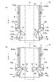
本発明の実施例1について、図1〜図7を参照して説明する。図1は、本発明の実施例1における杭切断装置の構成を説明する図で、(a)は切断ビット9が倒伏した図、(b)は切断ビット9が起立した図である。図2は、本発明の実施例1における杭切断装置の動作を説明する図で、(a)は切断ビット9が既設杭Pの切断を開始したときの図、(b)は切断ビット9が切断を完了する際の図である。図3は、本発明の実施例1におけるケーシング準備工程を説明する図である。図4は、本発明の実施例1におけるケーシング埋込工程を説明する図である。図5は、本発明の実施例1におけるケーシング埋込工程及びケーシング引抜き工程を説明する図である。図6は、本発明の実施例1における杭切断装置埋込工程、杭切断工程、及び杭引抜き工程を説明する図である。図7は、本発明の実施例1における地中に残った既設杭を引抜くための杭切断装置埋込工程、及び杭引抜き工程を説明する図である。
A first embodiment of the present invention will be described with reference to FIGS. 1A and 1B are diagrams illustrating a configuration of a pile cutting device according to a first embodiment of the present invention. FIG. 1A is a diagram in which a cutting bit 9 is lying down, and FIG. 1B is a diagram in which a cutting bit 9 is erected. 2A and 2B are diagrams for explaining the operation of the pile cutting device according to the first embodiment of the present invention. FIG. 2A is a view when the cutting bit 9 starts cutting the existing pile P, and FIG. It is a figure at the time of completing cutting. FIG. 3 is a diagram illustrating a casing preparation process in the first embodiment of the present invention. FIG. 4 is a diagram for explaining a casing embedding process in the first embodiment of the present invention. FIG. 5 is a diagram illustrating a casing embedding process and a casing drawing process in
(杭切断装置)
切断装置10は、図1に示すように、円筒型形状の装置本体3を有しており、上部は後述するようにケーシング20に継合できるように構成されている(図示は省略している)。装置本体3の外周には第1の外側円筒部4が第1の駆動装置8の駆動により装置本体3に沿って移動可能に設けられている。装置本体3は、一部に貫通する窓が設けられ、当該窓を介して第1の上アーム1(1a、1b)と第1の下アーム2(2a、2b)とが装置本体3の断面中心側に起立(図1(b)参照)、又は装置本体3の内周壁3N側に倒伏(図1(a)参照)するように設けられている。
(Pile cutting device)
As shown in FIG. 1, the cutting
第1の下アーム2(2a、2b)は端部がくり抜かれたコの字型をしていて、このくり抜かれた個所に第1の上アーム1(1a、1b)が入り込む構成となっている。第1の上アーム1(1a、1b)の一方の端部は第1の上アーム固定軸取付け部12(12a、12b)において第1の上アーム固定軸5(5a、5b)により装置本体3の長手方向と直交する方向に軸支されている。また、第1の下アーム2(2a、2b)の一方の端部は第1の下アーム固定軸取付け部13(13a、13b)において第1の下アーム固定軸6(6a、6b)により装置本体3の長手方向と直交する方向に軸支されている。そして、図1に示すように、第1の上アーム固定軸取付け部12(12a、12b)は、第1の外側円筒部4の下端部に設けられており、第1の下アーム固定軸取付け部13(13a、13b)は、第1の外側円筒部4より下方(装置本体先端方向D)における装置本体3の外周壁部に設けられている。つまり、第1の上アーム1(1a、1b)は、第1の上アーム固定軸5(5a、5b)により第1の外側円筒部4の下端部に軸支され、第1の下アーム2(2a、2b)は、第1の下アーム固定軸6(6a、6b)により第1の外側円筒部4より下方の装置本体3の外周壁部に軸支されている。さらに、第2の下アーム2(2a、2b)のくり抜かれた個所において、第1の可動軸7(7a、7b)により第1の上アーム1(1a、1b)と第1の下アーム2(2a、2b)のそれぞれの他方の端部が軸支されている。
The first lower arm 2 (2a, 2b) has a U-shape with a hollowed end, and the first upper arm 1 (1a, 1b) enters the hollowed portion. Yes. One end of the first upper arm 1 (1a, 1b) is connected to the apparatus
第1の上アーム1(1a、1b)の他方の端部を延長するように切断ビット9(9a、9b)が設けられている。切断ビット9(9a、9b)の先端には、ダイヤモンド等からなる超硬質ビットが設けられ、これによって既設杭Pを切断することができる。 Cutting bits 9 (9a, 9b) are provided to extend the other end of the first upper arm 1 (1a, 1b). An ultra-hard bit made of diamond or the like is provided at the tip of the cutting bit 9 (9a, 9b), whereby the existing pile P can be cut.
ここで、第1の上アーム1(1a、1b)の長さは、第1の下アーム2(2a、2b)よりも短く構成されている。このため、後述するように、第1の上アーム1(1a、1b)は、装置本体3の先端方向Dに対してほぼ直交する方向に起立させることができるとともに、第1の上アーム1(1a、1b)をサポートする位置に第1の下アーム2(2a、2b)を起立させることができる(図1(b)参照)。
Here, the length of the first upper arm 1 (1a, 1b) is shorter than that of the first lower arm 2 (2a, 2b). Therefore, as will be described later, the first upper arm 1 (1a, 1b) can be erected in a direction substantially perpendicular to the distal direction D of the
第1の上アーム1(1a、1b)及び第1の下アーム2(2a、2b)は鉄を主材料として構成され、切断する既設杭Pの直径に対応する寸法を有している。具体的には、切断ビット9(9a、9b)が完全に起立したときに、既設杭Pの直径の半分以上内部に入り込めるように、第1の上アーム1(1a、1b)、第1の下アーム2(2a、2b)、及び切断ビット9(9a、9b)の長さが構成されている。 The first upper arm 1 (1a, 1b) and the first lower arm 2 (2a, 2b) are made of iron as a main material and have dimensions corresponding to the diameter of the existing pile P to be cut. Specifically, when the cutting bit 9 (9a, 9b) is completely erected, the first upper arm 1 (1a, 1b), the first The lengths of the lower arm 2 (2a, 2b) and the cutting bit 9 (9a, 9b) are configured.
実施例1においては、第1の駆動装置8(8a、8b)を油圧シリンダで構成しており、第1の駆動装置8(8a、8b)が圧縮すると第1の外側円筒部4が装置本体先端方向Dとは逆方向に移動され、伸長すると第1の外側円筒部4が装置本体先端方向Dに移動される。したがって、第1の駆動装置8の圧縮により、図1(a)に示すように、第1の外側円筒部4を装置本体3の先端方向Dと逆方向に移動させて、第1の上アーム1(1a、1b)が内周壁3N側に倒伏する。そして、第1の上アーム1(1a、1b)が内周壁3N側に倒伏することにより、第1の上アーム1(1a、1b)の他方の端部に第1の下アーム2(2a、2b)の他方の端部が軸支されていることにより、第1の下アーム2(2a、2b)も内周壁3N側に倒伏する。さらに、第1の上アーム1(1a、1b)の他方の端部に延長するように設けられた切断ビット9(9a、9b)も内周壁3N側に倒伏する。
In the first embodiment, the first driving device 8 (8a, 8b) is constituted by a hydraulic cylinder, and when the first driving device 8 (8a, 8b) compresses, the first outer
なお、実施例1においては、第1の上アーム1(1a、1b)、第1の下アーム2(2a、2b)、及び切断ビット9(9a、9b)が、内周壁3N側に倒伏するように構成したが、より好ましくは、内周壁3Nより外側に倒伏するように構成するとよい。これにより、後述するケーシング埋込工程において、土圧の影響による第1の上アーム1(1a、1b)、第1の下アーム2(2a、2b)、及び切断ビット9(9a、9b)が必要以上に外側に倒伏することを防止できるため、第1の駆動装置8(8a、8b)が伸長した際に第1の上アーム1(1a、1b)、第1の下アーム2(2a、2b)、及び切断ビット9(9a、9b)が内側ではなく外側に起立してしまうことや起立しにくくなることを防げる。
In the first embodiment, the first upper arm 1 (1a, 1b), the first lower arm 2 (2a, 2b), and the cutting bit 9 (9a, 9b) lie down on the inner
図1(b)は、第1の駆動装置8(8a、8b)が伸長し、第1の上アーム1(1a、1b)、第1の下アーム2(2a、2b)、及び切断ビット9(9a、9b)が装置本体3の断面中心側に起立している状態を示している。つまり、第1の駆動装置8(8a、8b)が伸長して第1の外側円筒部4を装置本体3の先端方向Dに移動させることによって、第1の上アーム1(1a、1b)、第1の下アーム2(2a、2b)、及び切断ビット9(9a、9b)は装置本体3に貫通して設けた窓を利用して装置本体3の内周壁3Nより内側に起立する。
In FIG. 1 (b), the first driving device 8 (8a, 8b) is extended, the first upper arm 1 (1a, 1b), the first lower arm 2 (2a, 2b), and the cutting bit 9 (9a, 9b) shows a state in which the apparatus
なお、実施例1においては、第1の上アーム、第1の下アーム、及び切断ビットの数をそれぞれ2個としたが、必ずしもこれに限定されず切断する既設杭Pの硬さや直径に応じて適宜変更が可能である。例えば、第1の上アーム、第1の下アーム、及び切断ビットの数をそれぞれ3個以上としてもよい。また、実施例1では第1の駆動装置を2個備えるようにしたが、必ずしもこれに限定されず、既設杭Pの硬さ等により適宜変更が可能である。例えば、第1の上アーム、第1の下アーム、及び切断ビットの数にあわせて第1の駆動装置を3個以上としてもよい。 In the first embodiment, the number of the first upper arm, the first lower arm, and the cutting bit is two. However, the number is not necessarily limited to this, depending on the hardness and diameter of the existing pile P to be cut. Can be changed as appropriate. For example, the number of the first upper arm, the first lower arm, and the cutting bit may be three or more. In the first embodiment, two first driving devices are provided. However, the first driving device is not necessarily limited thereto, and can be appropriately changed depending on the hardness of the existing pile P or the like. For example, three or more first driving devices may be used in accordance with the number of first upper arms, first lower arms, and cutting bits.
次に、杭切断装置10の動作について説明する。杭切断装置10は、主に地中に埋め込まれた既設杭Pを切断する際に用いられる。既設杭Pの周囲に埋め込まれた杭切断装置10は、まず、図2(a)に示すように、第1の駆動装置8(8a、8b)を伸長して切断ビット9(9a、9b)を既設杭Pに当接させる。そして、杭切断装置10を回転させて、切断ビット9(9a、9b)により既設杭Pの切断を開始する。
Next, the operation of the
既設杭P切断の進捗に応じて、杭切断装置10の回転に加えて、第1の駆動装置8(8a、8b)をさらに伸長させて第1の上アーム1(1a、1b)、第1の下アーム2(2a、2b)、及び切断ビット9(9a、9b)を装置本体3の断面中心側に徐々に起立させていく。同時に、杭切断装置10をさらに地中へ徐々に埋め込んでいく。これによって、最終的には図2(b)に示すように、切断ビット9(9a、9b)は第1の上アーム1(1a、1b)とともにほぼ水平に起立する。切断ビット9(9a、9b)及び第1の上アーム1(1a、1b)がほぼ水平に起立すれば、第1の駆動装置8(8a、8b)の伸長及び杭切断装置10の地中への埋め込みを停止する。そして、杭切断装置10を少し引き上げながら、回転を継続すると、既設杭Pは自然に切断されて切断後の下方側の既設杭Pは下方に落下することになる。
In accordance with the progress of the cutting of the existing pile P, in addition to the rotation of the
なお、実施例1においては、第1の駆動装置8(8a、8b)を油圧シリンダで構成したが、必ずしもこれに限定されず適宜変更が可能である。例えば、モータ駆動等他の駆動装置を用いるように構成してもよい。 In the first embodiment, the first driving device 8 (8a, 8b) is constituted by a hydraulic cylinder, but is not necessarily limited to this and can be changed as appropriate. For example, you may comprise so that other drive devices, such as a motor drive, may be used.
また、実施例1においては、切断ビット9(9a、9b)を第1の上アーム1(1a、1b)の他方の端部に延長するように設けたが、必ずしもこれに限定されず適宜変更が可能である。例えば、第1の下アーム2(2a、2b)の他方の端部に延長するように設けてもよい。この場合は、第1の下アーム2(2a、2b)と所定の角度を有して延長するように設けるとよい。 In the first embodiment, the cutting bit 9 (9a, 9b) is provided so as to extend to the other end of the first upper arm 1 (1a, 1b). Is possible. For example, you may provide so that it may extend to the other edge part of the 1st lower arm 2 (2a, 2b). In this case, it is preferable to provide the first lower arm 2 (2a, 2b) so as to extend at a predetermined angle.
このような杭切断装置10を用いて、地中にて既設杭Pを切断してから引抜くようにすれば、地上における既設杭Pの切断作業やワイヤー掛け作業が不要となり、作業者が地中に引き込まれる危険がなくなり、安全に既設杭Pを引抜くことができる。
If the existing pile P is cut in the ground using such a
(杭切断装置を用いた杭抜き工法)
まず、杭切断装置準備工程を実行して、第1の上アーム1(1a、1b)、第1の下アーム2(2a、2b)、及び切断ビット9(9a、9b)が、内周壁3N側に倒伏した上述の杭切断装置10を準備する。
(Pile removal method using a pile cutting device)
First, the pile cutting device preparation step is executed, and the first upper arm 1 (1a, 1b), the first lower arm 2 (2a, 2b), and the cutting bit 9 (9a, 9b) are connected to the inner
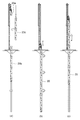
次に、ケーシング準備工程を実行して、複数の分割ケーシングを継合し、かつ最下端に掘削刃を有した円筒状のケーシング20を準備する。詳しく説明すると、図3に示すように、キャタピラ移動が可能で組立が容易なテレスコクローラ杭抜き機100を準備する。このテレスコクローラ杭抜き機100はクレーン40により分割ケーシングを5個継合させたケーシング20を油圧式減速機30により吊り下げる。油圧式減速機30は、リーダー50に沿って移動し、ケーシング20を回転させて最下端に設けられた掘削刃で土を掘りながら地中に埋め込む。また、各分割ケーシングはそれぞれボルトで継合されていて取外しや継ぎ足しが可能な構成とされている。
Next, a casing preparation process is executed to prepare a
地中には、既設杭Pが埋設されている。本発明における対象の既設杭Pは、おおよそ直径が500mmφ〜1800mmφ、長さが6m〜22mであり、材質は、セメント(PC杭)、松(松杭)、鋼管(鋼管杭)等である。ケーシング20は既設杭の直径や長さに合わせて選択される。すなわち、ケーシング20の内径が既設杭Pの直径より大きく、長さが既設杭Pの長さに応じた長さのものを準備する。そして、既設杭Pは、その頭部が見えるように土を掘削しておく。
An existing pile P is buried in the ground. The target existing pile P in the present invention has a diameter of about 500 mmφ to 1800 mmφ and a length of 6 m to 22 m, and the material is cement (PC pile), pine (pine pile), steel pipe (steel pipe pile), and the like. The
なお、実施例1においては、準備するケーシング20における分割ケーシングの数を5個としたが、必ずしもこれに限定されず、既設杭Pの長さ等の都合により適宜変更が可能である。例えば、4個以下としてもよいし、6個以上としてもよい。また、後述するように、ケーシング埋込工程において、既設杭Pの長さに応じて、さらに分割ケーシングを継ぎ足していくことができる。
In addition, in Example 1, although the number of the division | segmentation casings in the
次に、既設杭Pの周囲に位置するように、ケーシング20を地中に埋め込むケーシング埋込み工程を実行する。図4(a)に示すように、ケーシング20を既設杭Pの周囲に位置決めして下降させ、図4(b)に示すように、油圧式減速機30でケーシング20を回転させながら掘削刃で土を掘って地中に埋め込む。そして、図4(c)に示すように、ケーシング20の最上部の分割ケーシングが地上近くまで埋め込みが進めば、一旦、埋め込みを停止して最上部の分割ケーシングとその直下の分割ケーシングとを分離し最上部の分割ケーシングを持ち上げる。
Next, a casing embedding step for embedding the
そして、図5(a)に示すように、新たな分割ケーシング20cを継ぎ足す。つまり、複数の分割ケーシング20cを最上部の分割ケーシング下端と地中に埋め込まれたケーシング20bの最上端とをボルトで継合する。この分割ケーシング20cの継ぎ足しは、場所打ち杭のように既設杭Pの長さが長いために一度に長いケーシング20を埋め込むことができない場合に実施する。すなわち、既設杭Pの長さが短い場合は、この分割ケーシング20cの継ぎ足しは必要ない。そして、図5(b)に示すように、油圧式減速機30でケーシング20を回転させながら既設杭Pより深くケーシング20を埋め込む。これにより、既設杭Pは土圧から解放され、既設杭Pを引抜くことが可能となる。そして、ケーシング引抜き工程を実行して、ケーシング20を地中から引き抜く(図5(c)参照)。
Then, as shown in FIG. 5A, a new divided
なお、1500φクラス以上の既設杭Pの場合は、油圧式減速機30でケーシング20を回転させて地中に埋め込むことが困難となる場合がある。この場合は、チュービング装置と呼ばれる地表に設置した専用の装置を使ってケーシング20を回転させて地中に埋め込む。
In the case of an existing pile P of 1500φ class or more, it may be difficult to rotate the
次に、図6(a)に示すように、ケーシング20の最下端に準備した杭切断装置10を継合させる。そして、杭切断装置10を既設杭Pに沿って、地中に埋め込む。既設杭Pの切断予定個所まで杭切断装置10が埋め込まれれば、埋め込みを停止して、杭切断工程を実行する。
Next, as shown in FIG. 6A, the prepared
杭切断工程では、切断ビット9(9a、9b)を既設杭Pに当接するまで起立させて、ケーシング20及び杭切断装置10を回転させる。これにより徐々に既設杭Pは切断されていく。そして、切断の進捗に合わせてさらに切断ビット9(9a、9b)を起立させるとともに、さらに杭切断装置10を地中に埋め込む(図6(b)参照)。そして、図2(b)に示すように切断ビット9(9a、9b)がほぼ水平に起立するところまで切断が進めば、切断ビット9(9a、9b)の起立と杭切断装置10の地中に埋め込みを停止し、杭切断装置10の回転を継続しながら引き上げる。そうすると、既設杭Pは自重により完全に切断され、切断後の下方の既設杭Pは地中に落下する(図6(c)参照)。
In the pile cutting process, the cutting bit 9 (9a, 9b) is erected until it abuts against the existing pile P, and the
次に、杭引抜き工程を実行する。すなわち、第1の上アーム1(1a、1b)、第1の下アーム2(2a、2b)、及び切断ビット9(9a、9b)を装置本体3の断面中心側に起立させたまま杭切断装置10を引き上げることによって、切断後の上方の既設杭Pの最下端を支持して引抜くことができる。
Next, a pile drawing process is executed. That is, the pile cutting is performed with the first upper arm 1 (1a, 1b), the first lower arm 2 (2a, 2b), and the cutting bit 9 (9a, 9b) standing on the center side of the cross section of the
次に、残杭引抜き工程を実行して、地中に残された切断後の下方の既設杭Pを引抜く。即ち、図7(a)に示すように、ケーシング20cを継ぎ足して長いケーシング20を構成して、杭切断装置10を地中に残された既設杭Pの最下端まで埋め込む(図7(b)参照)。そして、杭切断装置10の第1の上アーム1(1a、1b)、第1の下アーム2(2a、2b)、及び切断ビット9(9a、9b)を装置本体3の断面中心側に起立させて、既設杭Pの最下端を支持させるか、最下方の部分を切断ビット9(9a、9b)で把持して、ケーシング20及び杭切断装置10を引抜く。これにより、地中に残された切断後の下方の既設杭Pは地上に引抜くことができる(図7(c)参照)。
Next, a remaining pile drawing process is performed and the existing pile P below the cut after being left in the ground is pulled out. That is, as shown to Fig.7 (a), the
従来、長く重い既設杭Pの引抜きに際しては、ワイヤーを既設杭Pの頭部に引っ掛けて引抜くことが行われていたが、以上述べた杭切断装置10を用いた杭引抜き工法においてはワイヤー掛けの必要がなくなった。これによって、ワイヤー掛けの際に作業員が地中に引き込まれる事故をなくすことができ、重い既設杭を安全に引抜くことができる。
Conventionally, when pulling out a long and heavy existing pile P, the wire was hooked on the head of the existing pile P and pulled out. However, in the above-described pile pulling method using the
このように、本発明の実施例1においては、既設杭を切断する杭切断装置であって、
第1の外側円筒部を同芯に設けた円筒状の装置本体と、
前記第1の外側円筒部を前記装置本体に沿って移動させる第1の駆動装置と、
切断ビットと、を備え、
前記第1の駆動装置により前記第1の外側円筒部を前記装置本体に沿って移動させることによって、前記切断ビットを前記装置本体の断面中心側に起立、又は前記装置本体の内周壁側に倒伏するように構成したことを特徴とする杭切断装置を用いることにより、杭切断装置で長い既設杭を地中で切断してワイヤーを掛けることなく引抜くので、重い既設杭を安全に引抜くことができる。
Thus, in Example 1 of the present invention, a pile cutting device for cutting an existing pile,
A cylindrical apparatus body provided with a first outer cylindrical portion concentrically;
A first driving device for moving the first outer cylindrical portion along the device body;
A cutting bit, and
By moving the first outer cylindrical portion along the device main body by the first driving device, the cutting bit stands on the cross-sectional center side of the device main body or falls on the inner peripheral wall side of the device main body. By using a pile cutting device characterized in that it is configured to cut a long existing pile in the ground with a pile cutting device and pull it out without hanging a wire, so that a heavy existing pile can be pulled out safely Can do.
また、杭切断装置を用いた杭抜き工法であって、
第1の外側円筒部を同芯に設けた円筒状の装置本体と、前記第1の外側円筒部を前記装置本体に沿って移動させる第1の駆動装置と、切断ビットと、を備え、前記第1の駆動装置により前記第1の外側円筒部を前記装置本体に沿って移動させることによって、前記切断ビットを前記装置本体の断面中心側に起立、又は前記装置本体の内周壁側に倒伏するように構成した杭切断装置を準備する杭切断装置準備工程と、
複数の分割ケーシングを継合し、かつ最下端に掘削刃を有した円筒状のケーシングを準備するケーシング準備工程と、
既設杭の周囲に位置するように前記ケーシングを地中に埋め込むケーシング埋込み工程と、
前記ケーシングを引抜くケーシング引抜き工程と、
前記杭切断装置を既設杭の周囲に沿って地中に埋め込む杭切断装置埋込工程と、
前記杭切断装置により既設杭を切断する杭切断工程と、
切断した既設杭を引抜く杭引抜き工程と、を備えた杭切断装置を用いた杭抜き工法により、杭切断装置で長い既設杭を地中で切断してワイヤーを掛けることなく引抜くので、重い既設杭を安全に引抜くことができる。
In addition, a pile removal method using a pile cutting device,
A cylindrical device main body provided with a first outer cylindrical portion concentrically; a first drive device for moving the first outer cylindrical portion along the device main body; and a cutting bit, By moving the first outer cylindrical portion along the device main body by the first driving device, the cutting bit stands on the cross-sectional center side of the device main body or falls on the inner peripheral wall side of the device main body. A pile cutting device preparation process for preparing a pile cutting device configured as described above,
A casing preparation step of joining a plurality of divided casings and preparing a cylindrical casing having a drilling blade at the lowermost end;
A casing embedding step of embedding the casing in the ground so as to be located around an existing pile;
A casing pulling process for pulling out the casing;
Pile cutting device embedding step for embedding the pile cutting device in the ground along the periphery of the existing pile,
A pile cutting step of cutting an existing pile by the pile cutting device;
Pile pulling process using a pile cutting device equipped with a pile cutting process that pulls the existing pile that has been cut, and the pile cutting device cuts long existing piles in the ground and pulls them without laying wires. Existing piles can be pulled out safely.
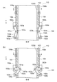
実施例2は、杭切断装置が切断ビットに加えて杭把持部を備えた点で実施例1と異なる。実施例2について、図8〜図11を参照して説明する。図8は、本発明の実施例2における杭切断装置の構成を説明する図で、(a)は側面図、(b)は底面図である。図9は、図8のA−A´断面図で、(a)は切断ビット109が倒伏した図、(b)は切断ビット109が起立した図である。図10は、図8のB−B´断面図で、(a)は第2の上アーム151及び第2の下アーム152が倒伏した図、(b)は第2の上アーム151及び第2の下アーム152が起立した図である。図11は、本発明の実施例2における杭切断装置埋込工程、杭切断工程、及び杭引抜き工程を説明する図である。 The second embodiment is different from the first embodiment in that the pile cutting device includes a pile gripping portion in addition to the cutting bit. A second embodiment will be described with reference to FIGS. 8A and 8B are diagrams illustrating the configuration of a pile cutting device according to the second embodiment of the present invention, in which FIG. 8A is a side view and FIG. 8B is a bottom view. 9A and 9B are cross-sectional views taken along the line AA ′ of FIG. 8, in which FIG. 9A is a diagram in which the cutting bit 109 is lying down, and FIG. 10A and 10B are cross-sectional views taken along the line BB ′ of FIG. 8, in which FIG. 10A shows the second upper arm 151 and the second lower arm 152 lying down, and FIG. 10B shows the second upper arm 151 and the second upper arm 151. It is the figure where the lower arm 152 stood up. FIG. 11 is a diagram illustrating a pile cutting device embedding process, a pile cutting process, and a pile drawing process in Example 2 of the present invention.
(杭切断装置)
実施例2における杭切断装置110は、主に、直径1500φ以上の特に太い既設杭Pを引抜く際に用いられる。杭切断装置110は、図8に示すように、切断ビット109(109a、109b、109c)に加えて、3つの杭把持部150を備えている。
(Pile cutting device)
The
杭切断ビット109(109a、109b、109c)は、実施例1と同様の構成を備えているが、3つの切断ビットを備えた点で異なっている。即ち、装置本体103の円周に沿って、120°毎に3つの切断ビット109(109a、109b、109c)が設けられている。また、杭把持部150は、装置本体103の円周に沿って、切断ビット109(109a、109b、109c)のそれぞれの中間の位置に120°毎に3つ設けられている。
The pile cutting bit 109 (109a, 109b, 109c) has the same configuration as that of the first embodiment, but is different in that it includes three cutting bits. That is, three cutting bits 109 (109a, 109b, 109c) are provided every 120 ° along the circumference of the apparatus
まず、切断ビット109(109a、109b、109c)の構成について説明する。装置本体103の外周には第1の外側円筒部104が第1の駆動装置108の駆動により装置本体103に沿って移動可能に設けられている。装置本体103は、一部に貫通する窓が設けられ、当該窓を介して第1の上アーム101(101a、101b、101c)と第1の下アーム102(102a、102b、102c)とが装置本体103の断面中心側に起立(図9(b)参照)、又は装置本体103の内周壁103N側に倒伏(図9(a)参照)するように設けられている。
First, the configuration of the cut bit 109 (109a, 109b, 109c) will be described. A first outer
第1の上アーム101(101a、101b、101c)は側面視で一部がくり抜かれたコの字型をしていて、このくり抜かれた個所に第1の下アーム102(102a、102b、102c)が入り込む構成となっている。第1の上アーム101(101a、101b、101c)の一方の端部は第1の上アーム固定軸取付け部112(112a、112b、112c)において第1の上アーム固定軸105(105a、105b、105c)により装置本体103の長手方向と直交する方向に軸支されている。また、第1の下アーム102(102a、102b、102c)の一方の端部は第1の下アーム固定軸取付け部113(113a、113b、113c)において第1の下アーム固定軸106(106a、106b、106c)により装置本体103の長手方向と直交する方向に軸支されている。そして、図9に示すように、第1の上アーム固定軸取付け部112(112a、112b、112c)は、第1の外側円筒部104の下端部に設けられており、第1の下アーム固定軸取付け部113(113a、113b、113c)は、第1の外側円筒部104より下方(装置本体先端方向D)における装置本体103の外周壁部に設けられている。つまり、第1の上アーム101(101a、101b、101c)は、第1の上アーム固定軸105(105a、105b、105c)により第1の外側円筒部104の下端部に軸支され、第1の下アーム102(102a、102b、102c)は、第1の下アーム固定軸106(106a、106b、106c)により第1の外側円筒部104より下方の装置本体103の外周壁部に軸支されている。さらに、第1の上アーム101(101a、101b、101c)のくり抜かれた個所において、第1の可動軸107(107a、107b、107c)により第1の上アーム101(101a、101b、101c)と第1の下アーム102(102a、102b、102c)のそれぞれの他方の端部が軸支されている。
The first upper arm 101 (101a, 101b, 101c) has a U shape with a part cut out in a side view, and the first lower arm 102 (102a, 102b, 102c) is formed in the cut out part. ) Enters. One end of the first upper arm 101 (101a, 101b, 101c) is connected to the first upper arm fixed shaft 105 (105a, 105b, 105c) at the first upper arm fixed shaft mounting portion 112 (112a, 112b, 112c). 105c) is axially supported in a direction orthogonal to the longitudinal direction of the apparatus
第1の上アーム101(101a、101b、101c)の他方の端部を延長するように切断ビット109(109a、109b、109c)が設けられている。切断ビット109(109a、109b、109c)の先端には、ダイヤモンド等からなる超硬質ビットが設けられ、これによって既設杭Pを切断することができる。 A cutting bit 109 (109a, 109b, 109c) is provided so as to extend the other end of the first upper arm 101 (101a, 101b, 101c). An ultra-hard bit made of diamond or the like is provided at the tip of the cutting bit 109 (109a, 109b, 109c), whereby the existing pile P can be cut.
第1の上アーム101(101a、101b、101c)及び第1の下アーム102(102a、102b、102c)は鉄を主材料として構成され、切断する既設杭Pの直径に対応する寸法を有している。具体的には、切断ビット109(109a、109b、109c)が完全に起立したときに、既設杭Pの直径の半分以上内部に入り込めるように、第1の上アーム101(101a、101b、101c)、第1の下アーム102(102a、102b、102c)、及び切断ビット109(109a、109b、109c)の長さが構成されている。 The first upper arm 101 (101a, 101b, 101c) and the first lower arm 102 (102a, 102b, 102c) are composed mainly of iron and have dimensions corresponding to the diameter of the existing pile P to be cut. ing. Specifically, when the cutting bit 109 (109a, 109b, 109c) is completely erected, the first upper arm 101 (101a, 101b, 101c) is able to enter the inside of more than half the diameter of the existing pile P. The length of the first lower arm 102 (102a, 102b, 102c) and the cutting bit 109 (109a, 109b, 109c) is configured.
実施例2においては、第1の駆動装置108(108a、108b、108c)を油圧シリンダで構成しており、第1の駆動装置108(108a、108b、108c)が圧縮すると第1の外側円筒部104が装置本体先端方向Dとは逆方向に移動され、伸長すると第1の外側円筒部104が装置本体先端方向Dに移動される。したがって、第1の駆動装置108の圧縮により、図9(a)に示すように、第1の外側円筒部104を装置本体103の先端方向Dと逆方向に移動させて、第1の上アーム101(101a、101b、101c)が内周壁103N側に倒伏する。そして、第1の上アーム101(101a、101b、101c)が内周壁103N側に倒伏することにより、第1の上アーム101(101a、101b、101c)の他方の端部に第1の下アーム102(102a、102b、102c)の他方の端部が軸支されていることにより、第1の下アーム102(102a、102b、102c)も内周壁103N側に倒伏する。さらに、第1の上アーム101(101a、101b、101c)の他方の端部に延長するように設けられた切断ビット109(109a、109b、109c)も内周壁103N側に倒伏する。
In the second embodiment, the first driving device 108 (108a, 108b, 108c) is constituted by a hydraulic cylinder, and the first outer cylindrical portion is compressed when the first driving device 108 (108a, 108b, 108c) is compressed. 104 is moved in the direction opposite to the apparatus main body front end direction D, and when extended, the first outer
図9(b)は、第1の駆動装置108(108a、108b、108c)が伸長し、第1の上アーム101(101a、101b、101c)、第1の下アーム102(102a、102b、102c)、及び切断ビット109(109a、109b、109c)が装置本体103の断面中心側に起立している状態を示している。つまり、第1の駆動装置108(108a、108b)が伸長して第1の外側円筒部104を装置本体103の先端方向Dに移動させることによって、第1の上アーム101(101a、101b、101c)、第1の下アーム102(102a、102b、102c)、及び切断ビット109(109a、109b)は装置本体103に貫通して設けた窓を利用して装置本体103の内周壁103Nより内側に起立する。
In FIG. 9B, the first driving device 108 (108a, 108b, 108c) is extended, and the first upper arm 101 (101a, 101b, 101c) and the first lower arm 102 (102a, 102b, 102c). ) And the cutting bit 109 (109a, 109b, 109c) stand up on the center side of the cross section of the apparatus
なお、実施例2においては、第1の上アーム、第1の下アーム、及び切断ビットの数をそれぞれ3個としたが、必ずしもこれに限定されず切断する既設杭Pの硬さや直径に応じて適宜変更が可能である。例えば、第1の上アーム、第1の下アーム、及び切断ビットの数をそれぞれ4個以上としてもよいし、2個でもよい。また、実施例1では第1の駆動装置を3個備えるようにしたが、必ずしもこれに限定されず、既設杭Pの硬さ等により適宜変更が可能である。例えば、第1の上アーム、第1の下アーム、及び切断ビットの数にあわせず第1の駆動装置を2個又は4個以上としてもよい。 In the second embodiment, the number of the first upper arm, the first lower arm, and the cutting bit is set to three. However, the number is not necessarily limited to this, depending on the hardness and diameter of the existing pile P to be cut. Can be changed as appropriate. For example, the number of the first upper arm, the first lower arm, and the cutting bit may be four or more, or two. In the first embodiment, three first driving devices are provided. However, the first driving device is not necessarily limited thereto, and can be appropriately changed depending on the hardness of the existing pile P or the like. For example, two or four or more first driving devices may be used in accordance with the number of first upper arms, first lower arms, and cutting bits.
杭把持部150は、円筒状の装置本体103と同芯に第1の外側円筒部104よりも装置本体先端方向Dと逆側に設けた第2の外側円筒部154を介して設けられ、第2の上アーム151(151a、151b、151c)及び第2の下アーム152(152a、152b、152c)を有している。第2の外側円筒部154は、第2の駆動装置158(158a、158b、158c)により装置本体103に沿って移動させることができる。
The
第2の外側円筒部154の外周壁下端部における第2の上アーム固定軸取付け部162(162a、162b、162c)にて、第2の上アーム151(151a、151b、151c)の一方の端部が第2の上アーム固定軸155(155a、155b、155c)により装置本体先端方向Dと直交する方向に軸支されている。また、第2の外側円筒部154より下方の装置本体外周壁部における第2の下アーム固定軸取付け部163(163a、163b、163c)にて、第2の下アーム152(152a、152b、152c)の一方の端部が第2の下アーム固定軸156(156a、156b、156c)により装置本体先端方向Dと直交する方向に軸支されている。
One end of the second upper arm 151 (151a, 151b, 151c) at the second upper arm fixed shaft mounting portion 162 (162a, 162b, 162c) at the lower end of the outer peripheral wall of the second outer
さらに、第2の上アーム151(151a、151b、151c)の他方の端部と第2の下アーム152(152a、152b、152c)の他方の端部とは、第2の可動軸157(157a、157b、157c)により、装置本体先端方向Dと直交する方向に軸支されている。 Further, the other end of the second upper arm 151 (151a, 151b, 151c) and the other end of the second lower arm 152 (152a, 152b, 152c) are connected to a second movable shaft 157 (157a). 157b, 157c), and is supported in a direction perpendicular to the front end direction D of the apparatus main body.
そして、第2の駆動装置158(158a、158b、158c)が伸長することにより、第2の外側円筒部154が装置本体先端方向Dに移動して第2の上アーム151(151a、151b、151c)及び第2の下アーム152(152a、152b、152c)が装置本体103の断面中心側に起立して杭把持動作を選択することができる。また、第2の駆動装置158(158a、158b、158c)が圧縮することにより、第2の外側円筒部154が装置本体先端方向Dと逆方向に移動して第2の上アーム151(151a、151b、151c)及び第2の下アーム152(152a、152b、152c)が装置本体103の内周壁103N側に倒伏して杭把持解除動作を選択することができる。
Then, when the second driving device 158 (158a, 158b, 158c) is extended, the second outer
杭把持部150が、杭把持動作を選択することによって、既設杭Pをしっかりと把持することができ、後述の杭引抜き工程において、切断後の既設杭Pを確実に引抜くことができる。また、杭把持部150が、杭把持解除動作を選択することによって、後述の杭切断装置埋込工程において、土圧の影響をなくして杭切断装置を地中に埋め込むことができる。
When the
なお、杭把持解除動作は、杭切断装置埋込工程以外にも選択してもよい。例えば、切断ビット起立工程や杭切断工程において選択することとしてよい。少なくとも杭切断装置埋込工程において、杭把持解除動作を選択すればよい。 Note that the pile grip releasing operation may be selected in addition to the pile cutting device embedding step. For example, it is good also as selecting in a cutting bit standing-up process or a pile cutting process. At least in the pile cutting device embedding step, the pile grip releasing operation may be selected.
また、既設杭Pの把持を確実なものとするために、第2の上アーム151(151a、151b、151c)又は第2の下アーム152(152a、152b、152c)の他方の端部に鋭利な爪を設けてもよい。 Further, in order to ensure the grip of the existing pile P, the second upper arm 151 (151a, 151b, 151c) or the second lower arm 152 (152a, 152b, 152c) is sharpened at the other end. Nails may be provided.
(杭切断装置を用いた杭抜き工法)
実施例2における杭切断装置を用いた杭抜き工法は、杭切断装置準備工程、ケーシング準備工程、ケーシング埋込み工程、及びケーシング引抜き工程までは実施例1と同様である。但し、杭切断装置準備工程で準備するものは、上述した杭切断装置110である。そして、杭切断装置埋込工程、杭切断工程、及び杭引抜き工程は、実施例1と異なっている。
(Pile removal method using a pile cutting device)
The pile drawing method using the pile cutting device in the second embodiment is the same as that in the first embodiment until the pile cutting device preparation step, the casing preparation step, the casing embedding step, and the casing drawing step. However, what is prepared in the pile cutting device preparation step is the above-described
実施例2における杭切断装置埋込工程を説明する。図11(a)に示すように、ケーシング20の最下端に準備した杭切断装置110を継合させる。そして、杭切断装置110を既設杭Pに沿って、地中に埋め込む。このとき、3か所の杭把持部150は杭把持解除動作を選択し、切断ビット109(109a、109b、109c)は、装置本体103の内周壁103N側に倒伏させておく。既設杭Pの切断した個所まで杭切断装置110が埋め込まれれば、埋め込みを停止して、杭切断工程を実行する。
The pile cutting device embedding process in Example 2 will be described. As shown in FIG. 11A, the prepared
杭切断工程では、3か所の杭把持部150は杭把持解除動作を選択する。そして、切断ビット109(109a、109b、109c)を既設杭Pに当接するまで起立させて、ケーシング20及び杭切断装置110を回転させる。これにより徐々に既設杭Pは切断されていく。これに伴って、切断の進捗に合わせてさらに切断ビット109(109a、109b、109c)を起立させるとともに、さらに杭切断装置110を地中に埋め込む(図11(b)参照)。そして、図9(b)に示すように切断ビット109(109a、109b、109c)がほぼ水平に起立するところまで切断が進めば、切断ビット109(109a、109b、109c)の起立と杭切断装置110の地中に埋め込みを停止し、杭切断装置110の回転を継続しながら引き上げる。そうすると、切断後の下方の既設杭Pは自重により下方に落下して切断が完了する(図11(c)参照)。
In the pile cutting process, the three
次に、杭引抜き工程を実行する。すなわち、第1の上アーム101(101a、101b、101c)、第1の下アーム102(102a、102b、102c)、及び切断ビット109(109a、109b、109c)を装置本体103の断面中心側に起立させたまま、3か所の杭把持部150は杭把持動作を選択する。即ち、第2の駆動装置158(158a、158b、158c)を伸長させて、第2の外側円筒部154を装置本体先端方向Dに移動させ、第2の上アーム151(151a、151b、151c)及び第2の下アーム152(152a、152b、152c)が装置本体103の断面中心側に起立して杭把持動作を選択する。これによって、既設杭Pは、切断ビット109(109a、109b、109c)によって最下端を支持されるとともに、杭把持部150における第2の上アーム151(151a、151b、151c)及び第2の下アーム152(152a、152b、152c)によって既設杭Pの最下端より若干上部をしっかりと把持される。そして、杭切断装置110を引き上げることによって、切断後の上方の既設杭Pを引抜くことができる。
Next, a pile drawing process is executed. That is, the first upper arm 101 (101a, 101b, 101c), the first lower arm 102 (102a, 102b, 102c), and the cutting bit 109 (109a, 109b, 109c) are arranged on the center side of the cross section of the apparatus
地中に残った既設杭Pは、杭切断装置110を用いて実施例1と同様に残杭引抜き工程を実施して引抜く。
The existing pile P remaining in the ground is pulled out using the
このように、実施例2においては、切断した既設杭を把持可能な杭把持部を備え、 前記杭把持部は、第2の駆動装置により、杭把持動作又は杭把持解除動作を選択可能な構成とすることにより、切断した太く重い既設杭でも杭把持部により把持して引抜くことができるとともに、杭切断装置で長い既設杭を地中で切断してワイヤーを掛けることなく引抜くので、重い既設杭を安全に引抜くことができる。 Thus, in Example 2, it is provided with the pile holding part which can hold the cut existing pile, The pile holding part can choose pile holding operation or pile holding release operation with the 2nd drive device. It is possible to hold and pull out a thick and heavy existing pile that has been cut by a pile gripping part, and to cut a long existing pile in the ground with a pile cutting device and pull it without applying a wire. Existing piles can be pulled out safely.
また、前記杭切断装置は、第2の駆動装置により、杭把持動作と杭把持解除動作とを選択可能な杭把持部を備え、
前記杭引抜き工程において、
前記第2の駆動装置により把持動作を選択して既設杭を把持するとともに、
少なくとも前記杭切断装置埋込工程において、
前記第2の駆動装置により杭把持解除動作を選択して既設杭の把持を解除することにより、切断した太く重い既設杭でも杭把持部により把持して引抜くことができるとともに、杭切断装置で長い既設杭を地中で切断してワイヤーを掛けることなく引抜くので、重い既設杭を安全に引抜くことができる。
Further, the pile cutting device includes a pile gripping portion that can select a pile gripping operation and a pile grip releasing operation by the second driving device,
In the pile drawing process,
While selecting a gripping operation by the second driving device and gripping an existing pile,
At least in the pile cutting device embedding step,
By selecting the pile grip release operation by the second driving device and releasing the grip of the existing pile, even a thick and heavy existing pile that has been cut can be gripped and pulled out by the pile grip portion, Since a long existing pile is cut in the ground and pulled without laying a wire, a heavy existing pile can be safely pulled out.
本発明における杭切断装置、及び杭切断装置を用いた杭抜き工法は、既設杭引抜きの分野に広く用いることができる。 The pile cutting device according to the present invention and the pile drawing method using the pile cutting device can be widely used in the field of existing pile drawing.
1(1a、1b):第1の上アーム 2(2a、2b):第1の下アーム
3:装置本体 3N:内周壁 4:第1の外側円筒部
5(5a、5b):第1の上アーム固定軸
6(6a、6b):第1の下アーム固定軸
7(7a、7b):第1の可動軸
8(8a、8b):第1の駆動装置 9(9a、9b):切断ビット
10:杭切断装置
12(12a、12b):第1の上アーム固定軸取付け部
13(13a、13b):第1の下アーム固定軸取付け部
20:ケーシング 30:油圧式減速機 40:クレーン
50:リーダー 100:テレスコクローラ杭抜き機
101(101a、101b、101c):第1の上アーム
102(102a、102b、102c):第1の下アーム
103:装置本体 103N:内周壁 104:第1の外側円筒部
105(105a、105b、105c):第1の上アーム固定軸
106(106a、106b、106c):第1の下アーム固定軸
107(107a、107b、107c):第1の可動軸
108(108a、108b、108c):第1の駆動装置
109(109a、109b、109c):切断ビット
110:杭切断装置
112(112a、112b、112c):第1の上アーム固定軸取付け部
113(113a、113b、113c):第1の下アーム固定軸取付け部
151(151a、151b、151c):第2の上アーム
152(152a、152b、152c):第2の下アーム
154:第2の外側円筒部
155(155a、155b、155c):第2の上アーム固定軸
156(156a、156b、156c):第2の下アーム固定軸
157(157a、157b、157c):第2の可動軸
158(158a、158b、158c):第2の駆動装置
162(162a、162b、162c):第2の上アーム固定軸取付け部
163(163a、163b、163c):第2の下アーム固定軸取付け部
D:装置本体先端方向 P:既設杭
1 (1a, 1b): first upper arm 2 (2a, 2b): first lower arm
3: Device
5 (5a, 5b): first upper arm fixed shaft
6 (6a, 6b): first lower arm fixing shaft
7 (7a, 7b): first movable shaft
8 (8a, 8b): First driving device 9 (9a, 9b): Disconnect bit
10: Pile cutting device
12 (12a, 12b): first upper arm fixed shaft mounting portion
13 (13a, 13b): first lower arm fixed shaft mounting portion
20: Casing 30: Hydraulic reducer 40: Crane
50: Leader 100: Telescopic crawler pile remover
101 (101a, 101b, 101c): first upper arm
102 (102a, 102b, 102c): first lower arm
103: apparatus
105 (105a, 105b, 105c): first upper arm fixed shaft
106 (106a, 106b, 106c): First lower arm fixing shaft
107 (107a, 107b, 107c): first movable shaft
108 (108a, 108b, 108c): first driving device
109 (109a, 109b, 109c): Disconnect bit
110: Pile cutting device
112 (112a, 112b, 112c): First upper arm fixed shaft mounting portion
113 (113a, 113b, 113c): First lower arm fixed shaft mounting portion
151 (151a, 151b, 151c): second upper arm
152 (152a, 152b, 152c): second lower arm
154: Second outer cylindrical portion
155 (155a, 155b, 155c): second upper arm fixed shaft
156 (156a, 156b, 156c): second lower arm fixing shaft
157 (157a, 157b, 157c): second movable shaft
158 (158a, 158b, 158c): second driving device
162 (162a, 162b, 162c): second upper arm fixed shaft mounting portion
163 (163a, 163b, 163c): second lower arm fixed shaft mounting portion
D: Device body tip direction P: Existing pile
Claims (7)
第1の外側円筒部を同芯に設けた円筒状の装置本体と、
前記第1の外側円筒部を前記装置本体に沿って移動させる第1の駆動装置と、
切断ビットと、を備え、
前記第1の駆動装置により前記第1の外側円筒部を前記装置本体に沿って移動させることによって、前記切断ビットを前記装置本体の断面中心側に起立、又は前記装置本体の内周壁側に倒伏するように構成したことを特徴とする杭切断装置。 A pile cutting device for cutting an existing pile,
A cylindrical apparatus body provided with a first outer cylindrical portion concentrically;
A first driving device for moving the first outer cylindrical portion along the device body;
A cutting bit, and
By moving the first outer cylindrical portion along the device main body by the first driving device, the cutting bit stands on the cross-sectional center side of the device main body or falls on the inner peripheral wall side of the device main body. The pile cutting device characterized by comprising so that it may do.
前記第1の外側円筒部より下方の前記装置本体外周壁部に一方の端部が第1の下アーム固定軸により軸支された第1の下アームと、
前記第1の上アームの他方の端部と前記第1の下アームの他方の端部とを軸支する第1の可動軸と、を備え、
前記切断ビットは、前記第1の上アームの前記他の端部を延長するように設け、
前記第1の駆動装置により前記第1の外側円筒部が装置本体先端方向に移動して前記第1の上アーム及び前記第1の下アームが前記装置本体の断面中心側に起立し前記切断ビットが起立するとともに、前記第1の駆動装置により前記第1の外側円筒部が装置本体先端方向と逆方向に移動して前記第1の上アーム及び前記第1の下アームが前記装置本体の内周壁側に倒伏し前記切断ビットが倒伏することを特徴とする請求項1に記載の杭切断装置。 A first upper arm whose one end is pivotally supported by a first upper arm fixing shaft at the lower end of the outer peripheral wall of the first outer cylindrical portion;
A first lower arm whose one end is pivotally supported by a first lower arm fixing shaft on the outer peripheral wall portion of the apparatus body below the first outer cylindrical portion;
A first movable shaft that pivotally supports the other end of the first upper arm and the other end of the first lower arm;
The cutting bit is provided to extend the other end of the first upper arm;
The first driving device causes the first outer cylindrical portion to move toward the distal end of the apparatus body, so that the first upper arm and the first lower arm stand up toward the center of the cross section of the apparatus body, and the cutting bit. Rises, and the first driving device moves the first outer cylindrical portion in the direction opposite to the front end direction of the apparatus main body so that the first upper arm and the first lower arm are inside the apparatus main body. The pile cutting device according to claim 1, wherein the pile bit falls on the peripheral wall side and falls.
前記杭把持部は、第2の駆動装置により、杭把持動作又は杭把持解除動作を選択可能なことを特徴とする請求項1又は2に記載の杭切断装置。 It has a pile gripping part that can grip the existing pile that has been cut,
The pile cutting device according to claim 1 or 2, wherein the pile gripping portion can select a pile gripping operation or a pile grip releasing operation by a second driving device.
円筒状の前記装置本体と同芯に前記第1の外側円筒部よりも前記装置本体先端方向と逆側に設けた第2の外側円筒部と、
前記第2の外側円筒部を前記装置本体に沿って移動させる前記第2の駆動装置と、
前記第2の外側円筒部の外周壁下端部に一方の端部が第2の上アーム固定軸により軸支された第2の上アームと、
前記第2の外側円筒部より下方の前記装置本体外周壁部に一方の端部が第2の下アーム固定軸により軸支された第2の下アームと、
前記第2の上アームの他方の端部と前記第2の下アームの他方の端部とを軸支する第2の可動軸と、を備え、
前記第2の駆動装置により前記第2の外側円筒部が装置本体先端方向に移動して前記第2の上アーム及び前記第2の下アームが前記装置本体の断面中心側に起立して前記杭把持動作を選択するとともに、前記第2の駆動装置により前記第2の外側円筒部が装置本体先端方向と逆方向に移動して前記第2の上アーム及び前記第2の下アームが前記装置本体の内周壁側に倒伏して前記杭把持解除動作を選択することを特徴とする請求項3に記載の杭切断装置。 The pile gripping part is
A second outer cylindrical portion provided concentrically with the cylindrical device body on the opposite side of the device body tip direction from the first outer cylindrical portion;
The second driving device for moving the second outer cylindrical portion along the device body;
A second upper arm whose one end is pivotally supported by a second upper arm fixing shaft at the lower end of the outer peripheral wall of the second outer cylindrical portion;
A second lower arm whose one end is pivotally supported by a second lower arm fixing shaft on the outer peripheral wall portion of the apparatus main body below the second outer cylindrical portion;
A second movable shaft that pivotally supports the other end of the second upper arm and the other end of the second lower arm,
The second driving device causes the second outer cylindrical portion to move toward the distal end of the apparatus main body, and the second upper arm and the second lower arm stand up toward the center of the cross-section of the apparatus main body. A gripping operation is selected, and the second driving device moves the second outer cylindrical portion in the direction opposite to the distal end direction of the apparatus main body so that the second upper arm and the second lower arm are the apparatus main body. The pile cutting device according to claim 3, wherein the pile gripping release operation is selected by falling to the inner peripheral wall side of the pile.
第1の外側円筒部を同芯に設けた円筒状の装置本体と、前記第1の外側円筒部を前記装置本体に沿って移動させる第1の駆動装置と、切断ビットと、を備え、前記第1の駆動装置により前記第1の外側円筒部を前記装置本体に沿って移動させることによって、前記切断ビットを前記装置本体の断面中心側に起立、又は前記装置本体の内周壁側に倒伏するように構成した杭切断装置を準備する杭切断装置準備工程と、
複数の分割ケーシングを継合し、かつ最下端に掘削刃を有した円筒状のケーシングを準備するケーシング準備工程と、
既設杭の周囲に位置するように前記ケーシングを地中に埋め込むケーシング埋込み工程と、
前記ケーシングを引抜くケーシング引抜き工程と、
前記杭切断装置を既設杭の周囲に沿って地中に埋め込む杭切断装置埋込工程と、
前記杭切断装置により既設杭を切断する杭切断工程と、
切断した既設杭を引抜く杭引抜き工程と、を備えた杭切断装置を用いた杭抜き工法。 A pile removal method using a pile cutting device,
A cylindrical device main body provided with a first outer cylindrical portion concentrically; a first drive device for moving the first outer cylindrical portion along the device main body; and a cutting bit, By moving the first outer cylindrical portion along the device main body by the first driving device, the cutting bit stands on the cross-sectional center side of the device main body or falls on the inner peripheral wall side of the device main body. A pile cutting device preparation process for preparing a pile cutting device configured as described above,
A casing preparation step of joining a plurality of divided casings and preparing a cylindrical casing having a drilling blade at the lowermost end;
A casing embedding step of embedding the casing in the ground so as to be located around an existing pile;
A casing pulling process for pulling out the casing;
Pile cutting device embedding step for embedding the pile cutting device in the ground along the periphery of the existing pile,
A pile cutting step of cutting an existing pile by the pile cutting device;
A pile drawing method using a pile cutting device comprising: a pile drawing process for drawing a cut existing pile.
前記杭引抜き工程において、
前記第2の駆動装置により把持動作を選択して既設杭を把持するとともに、
少なくとも前記杭切断装置埋込工程において、
前記第2の駆動装置により杭把持解除動作を選択して既設杭の把持を解除することを特徴とする請求項5又は6に記載の杭切断装置を用いた杭抜き工法。
The pile cutting device includes a pile gripping portion capable of selecting a pile gripping operation and a pile grip releasing operation by a second driving device,
In the pile drawing process,
While selecting a gripping operation by the second driving device and gripping an existing pile,
At least in the pile cutting device embedding step,
The pile removal method using the pile cutting device according to claim 5 or 6, wherein the pile driving release operation is selected by the second driving device to release the existing pile.
Priority Applications (1)
| Application Number | Priority Date | Filing Date | Title |
|---|---|---|---|
| JP2017132419A JP2019015076A (en) | 2017-07-06 | 2017-07-06 | Pile cutting device, pile extraction method using pile cutting device |
Applications Claiming Priority (1)
| Application Number | Priority Date | Filing Date | Title |
|---|---|---|---|
| JP2017132419A JP2019015076A (en) | 2017-07-06 | 2017-07-06 | Pile cutting device, pile extraction method using pile cutting device |
Publications (1)
| Publication Number | Publication Date |
|---|---|
| JP2019015076A true JP2019015076A (en) | 2019-01-31 |
Family
ID=65357362
Family Applications (1)
| Application Number | Title | Priority Date | Filing Date |
|---|---|---|---|
| JP2017132419A Pending JP2019015076A (en) | 2017-07-06 | 2017-07-06 | Pile cutting device, pile extraction method using pile cutting device |
Country Status (1)
| Country | Link |
|---|---|
| JP (1) | JP2019015076A (en) |
Cited By (4)
| Publication number | Priority date | Publication date | Assignee | Title |
|---|---|---|---|---|
| JP2020200742A (en) * | 2019-06-07 | 2020-12-17 | 有限会社三友機工 | Pile holding body for pulling out underground pile and underground pile pulling out method using pile holding body |
| JP2021139254A (en) * | 2020-02-28 | 2021-09-16 | 有限会社マンダイクレーン | Existing pile cutting and removing device |
| JP2022032896A (en) * | 2020-08-12 | 2022-02-25 | 有限会社マンダイクレーン | Existing pile cutting-off removal device |
| JP2022035897A (en) * | 2020-08-20 | 2022-03-04 | 有限会社マンダイクレーン | Cutting bit |
-
2017
- 2017-07-06 JP JP2017132419A patent/JP2019015076A/en active Pending
Cited By (4)
| Publication number | Priority date | Publication date | Assignee | Title |
|---|---|---|---|---|
| JP2020200742A (en) * | 2019-06-07 | 2020-12-17 | 有限会社三友機工 | Pile holding body for pulling out underground pile and underground pile pulling out method using pile holding body |
| JP2021139254A (en) * | 2020-02-28 | 2021-09-16 | 有限会社マンダイクレーン | Existing pile cutting and removing device |
| JP2022032896A (en) * | 2020-08-12 | 2022-02-25 | 有限会社マンダイクレーン | Existing pile cutting-off removal device |
| JP2022035897A (en) * | 2020-08-20 | 2022-03-04 | 有限会社マンダイクレーン | Cutting bit |
Similar Documents
| Publication | Publication Date | Title |
|---|---|---|
| JP2019015076A (en) | Pile cutting device, pile extraction method using pile cutting device | |
| JP6284255B1 (en) | Pile cap and pile drawing method | |
| CN104532842B (en) | A kind of sleeve pipe revolution friction-type cutting-off method pile-pulling construction method | |
| JP6587900B2 (en) | Existing pile removal method and pile cutting device used to implement the method | |
| JP2008255603A (en) | Driving method of inner excavation pile under low and narrow restriction | |
| JPS6319328A (en) | Method and apparatus for constructing turning-penetrating type large-diameter steel tube | |
| JP2019035268A (en) | Pile cap of pile extraction machine, and pile extraction method using pile cap | |
| JP2009263966A (en) | Removal method of existing pile | |
| JP4714724B2 (en) | Hammer grab | |
| JP3361776B2 (en) | Crushing equipment for underground piles | |
| JP3219554U (en) | Pile driving device | |
| JP3683229B2 (en) | Existing pile removal method and equipment | |
| JP6758629B2 (en) | Existing pile gripping device | |
| JP5643061B2 (en) | How to remove existing piles | |
| JP3151453B2 (en) | Drilling rig for pipe burial | |
| JP4635725B2 (en) | Pile construction system | |
| JP6284253B1 (en) | Pile catcher and pile removal method using pile catcher | |
| JP6465511B2 (en) | Plucking machine chucking mechanism and pile removal method | |
| JP2018119260A (en) | Chucking mechanism of pile extractor and pile extraction method | |
| JP2011026936A (en) | Method and device for extracting buried pile | |
| JP6588502B2 (en) | Dismantling method for underground foundation pile | |
| JP6406685B1 (en) | Pile removal machine and pile removal method | |
| JPH10195873A (en) | Existing structure recovery method and apparatus in all casing construction method | |
| JPH10252065A (en) | Existing-structure recovering method in all-casing construction method and existing structure recovering device | |
| JPH0657749A (en) | Removal method for underground obstacle |