JP2019014381A - Parking support method and parking control device - Google Patents
Parking support method and parking control device Download PDFInfo
- Publication number
- JP2019014381A JP2019014381A JP2017133377A JP2017133377A JP2019014381A JP 2019014381 A JP2019014381 A JP 2019014381A JP 2017133377 A JP2017133377 A JP 2017133377A JP 2017133377 A JP2017133377 A JP 2017133377A JP 2019014381 A JP2019014381 A JP 2019014381A
- Authority
- JP
- Japan
- Prior art keywords
- parking
- target
- host vehicle
- empty
- vehicle
- Prior art date
- Legal status (The legal status is an assumption and is not a legal conclusion. Google has not performed a legal analysis and makes no representation as to the accuracy of the status listed.)
- Granted
Links
Images


Abstract
Description
本発明は、駐車支援方法及び駐車制御装置に関するものである。 The present invention relates to a parking assistance method and a parking control device.
従来から、基準位置から目標位置までの車両の走行経路を生成する走行制御装置が知られている(特許文献1)。特許文献1では、走行経路を走行した時の操舵量の累積値を算出し、操舵量の累積値が所定値を超えていれば、別の走行経路を生成する。操舵量の累積値が小さい走行経路を生成することにより、車両が蛇行するなどのおそれを無くし、車両の搭乗者に与える不快感を軽減している。 Conventionally, a travel control device that generates a travel route of a vehicle from a reference position to a target position is known (Patent Document 1). In Patent Document 1, a cumulative value of the steering amount when traveling on a travel route is calculated, and if the cumulative value of the steering amount exceeds a predetermined value, another travel route is generated. By generating a travel route with a small cumulative value of the steering amount, there is no fear of the vehicle meandering and the discomfort given to the passenger of the vehicle is reduced.
ところで、駐車支援技術において、車両が走行経路に沿って走行し始めた後に駐車目標(目標位置に相当)を変更する補正(「リアルタイム補正」という)を行う場合がある。駐車目標が正しく特定できていない状態でリアルタイム補正を行うと、駐車目標が大きな補正量で且つ繰り返し補正されることになる。このため、車両の挙動が安定せず、車両の乗員に違和感を与えてしまう。 By the way, in the parking assistance technology, there is a case where correction (referred to as “real time correction”) for changing the parking target (corresponding to the target position) after the vehicle starts to travel along the travel route may be performed. If real-time correction is performed in a state where the parking target is not correctly specified, the parking target is repeatedly corrected with a large correction amount. For this reason, the behavior of the vehicle is not stable, and the vehicle occupant is uncomfortable.
本発明は、上記課題に鑑みて成されたものであり、その目的は、リアルタイム補正により乗員に与える違和感を抑制することである。 The present invention has been made in view of the above problems, and an object thereof is to suppress a sense of discomfort given to the occupant by real-time correction.
本発明の一態様に係わる駐車制御装置の駐車支援方法は、自車両の周囲の空き駐車スペースを探索し、自車両の周囲の空き駐車スペースに駐車目標を設定し、空き駐車スペースを探索した結果に基づいて駐車目標が設定された空き駐車スペースの確信度が予め定めた第一駐車条件を満たすか否かを判定し、確信度が第一駐車条件を満たさないと判定した場合、駐車目標の補正を制限する。 The parking support method of the parking control device according to one aspect of the present invention is a result of searching for an empty parking space around the host vehicle, setting a parking target in the empty parking space around the host vehicle, and searching for an empty parking space. If the confidence level of the empty parking space for which the parking target is set is determined to satisfy the first parking condition set in advance, and it is determined that the certainty level does not satisfy the first parking condition, Limit correction.
本発明によれば、リアルタイム補正により乗員に与える違和感を抑制することができる。 According to the present invention, it is possible to suppress a sense of discomfort given to the occupant by real-time correction.
図面を参照して、実施形態を説明する。図面の記載において同一部分には同一符号を付して説明を省略する。なお、実施形態では、移動体が車両である場合について、説明する。 Embodiments will be described with reference to the drawings. In the description of the drawings, the same portions are denoted by the same reference numerals, and description thereof is omitted. In the embodiment, a case where the moving body is a vehicle will be described.
(第1実施形態)
<駐車制御装置の構成>
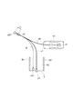
図1に示すように、駐車制御装置100は、車両制御ECU40に出力する舵角制御信号と速度制御信号を生成する。なお、本実施形態における駐車とは、自車両を空き駐車スペースに向けて移動し、空き駐車スペースに停車することをいう。車両においては、駐車場内の駐車スペースに、車両を止める為に、空き駐車スペースに移動し、空き駐車スペースに停車することをいう。
(First embodiment)
<Configuration of parking control device>
As shown in FIG. 1, the
駐車制御装置100は、自車両周囲センサ10、画像情報処理部20(駐車目標設定回路)、駐車支援演算部30(確信度判定回路、補正制限回路)、及び周囲画像生成回路101を備える。
The
画像情報処理部20、駐車支援演算部30、及び周囲画像生成回路101は、CPU(中央処理装置)、メモリ、及び入出力部を備えるマイクロコンピュータを用いて実現可能である。マイクロコンピュータをECUとして機能させるためのコンピュータプログラムを、マイクロコンピュータにインストールして実行する。これにより、マイクロコンピュータは、画像情報処理部20、駐車支援演算部30、及び周囲画像生成回路101として機能する。画像情報処理部20、駐車支援演算部30、及び周囲画像生成回路101の各機能は、1または複数の処理回路によって実装することができる。処理回路は、例えば電気回路を含む処理装置等のプログラムされた処理装置を含み、また実施形態に記載された機能を実行するようにアレンジされた特定用途向け集積回路(ASIC)や従来型の回路部品のような装置も含んでいる。
The image
なお、ここでは、ソフトウェアによって画像情報処理部20、駐車支援演算部30、及び周囲画像生成回路101を実現する例を示すが、もちろん、以下に示す各情報処理を実行するための専用のハードウェアを用意して、画像情報処理部20、駐車支援演算部30、及び周囲画像生成回路101を構成することも可能である。
In addition, although the example which implement | achieves the image
自車両周囲センサ10は、例えば、自車両の周囲を撮像する複数のカメラで構成される。カメラ10aは自車両の前方に搭載されて自車両前方を撮像する。カメラ10bは自車両の後方に搭載されて自車両後方を撮像する。カメラ10cは自車両の左側に搭載されて自車両左側を撮像する。カメラ10dは自車両の右側に搭載されて自車両右側を撮像する。それぞれのカメラは、自車両のルーフより下方に設置されるため、実際の自車両を撮像することは困難である。また、自車両のタイヤがタイヤハウス内に格納されているため、自車両のタイヤの外円面(タイヤを円柱とした場合の側面)を撮像することは困難である。すなわち、自車両及び自車両のタイヤを撮像が難しいため、実際の自車両及びタイヤの画像を得ることが難しい。そこで、実際の自車両の画像の代わりに後述の自車両アイコン(自車両を模した画像)を使用する。
The own
各カメラは、自車両のルーフより下方に設置されるため、実際に自車両の上方から撮像した画像を表示することは困難である。すなわち、カメラは自車両を撮像できないので、実際の自車両の画像を得ることができない。そこで、実際の自車両の画像の代わりに後述の自車両アイコン(自車両を模した画像)を使用する。 Since each camera is installed below the roof of the host vehicle, it is difficult to display an image actually captured from above the host vehicle. That is, since the camera cannot capture the own vehicle, an actual image of the own vehicle cannot be obtained. Therefore, a host vehicle icon (an image imitating the host vehicle) described later is used instead of the actual host vehicle image.
自車両周囲センサ10は、カメラ(10a〜10d)に限らず、他のセンサで構成してもよい。例えば、対象物に向けて赤外線レーザを照射し、その反射光の強度により対象物までの距離を測定するレーザレンジファインダ(LFR)等で構成してもよい。反射光の強度によって駐車枠を表す白線等の長さを検出することも可能である。また、超音波を利用するクリアランスソナーを用いてもよい。なお、本実施形態は、カメラ(10a〜10d)を用いて自車両周囲センサ10を構成した例で説明する。
The own
画像情報処理部20は、自車両周囲センサ10で撮像した自車両の周囲の画像情報を、画像認識して駐車支援に必要な情報を生成する。具体的には、画像情報処理部20は、自車両の周囲の空き駐車スペースに対して、駐車目標を設定する。駐車支援に必要な情報(駐車目標)は、駐車支援演算部30に出力される。
The image
駐車支援演算部30には、画像情報処理部20の他に、入力インターフェース51、車輪速センサ52、及び舵角センサ53が接続される。車両制御回路30は、自車両の位置を駐車目標に合わせるように駐車制御を実行する。駐車支援演算部30は、駐車支援に必要な各情報、車輪速センサ52で検出した自車両の車輪速情報、舵角センサ53で検出した舵角情報、及び入力インターフェース51に入力される駐車目標に関する各種の情報に基づいて、舵角制御信号と速度制御信号を生成する。駐車支援演算部30の出力は、車両制御ECU40に接続される。
In addition to the image
周囲画像生成回路101は、4台のカメラ2a〜2dで撮像された自車両周囲の画像に基づき、予め定めた仮想視点、投影面を設定し、自車両の上方から下方(自車両の方向)を見たように画像を生成する。上記のように各カメラは自車両を撮像できないので、生成した画像には自車両は含まれない。以下、この画像を「俯瞰画像」という。俯瞰画像はすなわち自車両周囲を自車両の上方から見た場合の画像である。俯瞰画像の生成方法は既知の技術であるので、詳細な説明を省略する。尚、本実施形態においては、必ずしも俯瞰画像である必要はなく、鳥瞰画像など、自車両の周囲を表示する画像(周囲画像)であればよい。また、本実施形態における周囲画像は、必ずしも自車両に設けられたカメラ2a〜2dにより撮像される必要はなく、駐車スペースの周囲に設けられたカメラで撮像した画像を用いるようにしてもよい。
The surrounding
自車両周囲センサ10、目標位置設定回路20、車両制御回路30、及び周囲画像生成回路101を備える駐車制御装置100によれば、自車両を空き駐車スペースの適切な位置に駐車させることができる。
According to the
入力インターフェース51は、自車両の乗員(操作者)が、駐車に関する各種の情報(駐車目標を含む)を入力する端末である。操作者が乗車している場合を想定して、自車両内にジョイスティックや操作スイッチ、表示部9に設けられるタッチパネルなど、自車両に搭載される各種の入力デバイスを設けてもよい。また、自車両に設置されているスピーカを用いて、乗員に各種の操作入力を促す音声案内を行うようにしてもよい。本実施形態では、入力インターフェース51が表示部9に設けられるタッチパネルである場合を例に取り、説明する。
The
車輪速センサ52は、自車両の車輪速を検出するセンサである。
The
舵角センサ53は、自車両の舵角を検出するセンサであり、ステアリングの回転軸に取り付けるエンコーダを用いるのが一般的である。
The
表示部9は、周囲画像生成回路101により生成された周囲画像を表示する。表示部9は、例えば、車室内に設置されているナビゲーション用の液晶ディスプレイや、遠隔操作端末に取り付けられた既存のモニタを使用することができる。
The
車両制御ECU40には、車輪速センサ52と舵角センサ53が接続される。車両制御ECU40の出力は、ステアリング舵角、車速等を制御するアクチュエータ50に接続される。車両制御ECU40は、舵角制御信号と速度制御信号に基づいて、自車両V1のブレーキペダル(制動)、アクセルペダル(駆動)、ステアリングホイール(操舵)を駆動するアクチュエータ50を制御する。駐車支援演算部30で設定された駐車経路に沿って自車両V1が移動するようにステアリング舵角と速度を制御すれば、自車両V1を、駐車目標p3に合わせて駐車させることができる。
A
尚、本実施形態における自動運転とは、例えば、ブレーキ(制動)、アクセル(駆動)、ステアリング(操舵)を駆動するアクチュエータ50の内、少なくとも一つのアクチュエータを運転者の操作なしに制御している状態のことを指す。そのため、少なくとも一つのアクチュエータが制御されている状態であれば、その他のアクチュエータが運転者の操作により作動していたとしても構わない。また、本実施形態における手動運転とは、例えば、ブレーキ、アクセル、ステアリングなど走行のために必要な操作をドライバが操作している状態のことを指す。
The automatic driving in the present embodiment is, for example, controlling at least one actuator among the
車両制御ECU40は、駐車支援演算部30で設定された駐車経路に沿って自車両が移動するように、自動運転を実行すれば、駐車動作時における運転者の操作負担をより低減できる。
If vehicle control ECU40 performs an automatic driving | operation so that the own vehicle may move along the parking path | route set by the parking
図2に示すように、画像情報処理部20は、目標駐車枠設定部21、目標駐車位置設定部22、駐車開始位置設定部23、現在位置推定部24、及び目標駐車枠検知部25を備える。
As shown in FIG. 2, the image
目標駐車枠設定部21は、乗員が入力インターフェース51としてのタッチパネルを用いて特定した表示部9の表示画面上の位置及び向きに、目標駐車枠を設定する。目標駐車枠設定部21は、設定した目標駐車枠の位置及び向きを目標駐車位置設定部22及び駐車経路生成部31に出力する。
The target parking
目標駐車位置設定部22は、目標駐車枠の位置及び向きに基づいて、空き駐車スペースR2内に駐車目標を設定する。図3は、駐車目標(目標駐車位置p3)に、自車両V1の後輪車軸中心の位置を合わせた例を示す。なお、駐車目標(目標駐車位置p3)に、自車両V1上のどの位置を合わせるかは、駐車方式(後退又は前進)によって異なる。また、「駐車目標」は、駐車可能空間X1における駐車目標の位置(目標駐車位置p3)及び目標駐車位置p3における自車両V1の姿勢(進行方向)を含む概念である。つまり、目標駐車位置設定部22は、目標駐車枠の位置及び向きに基づいて、目標駐車位置p3及び目標駐車位置p3における自車両V1の姿勢の少なくとも一方を設定する。以後、「駐車目標」の例として目標駐車位置p3を挙げて説明する。尚、本実施形態において、駐車目標に体操させる自車両V1の位置を後輪車軸中心としたが、必ずしもこれに限らず、予め設定する基準位置であれば限られない。
The target parking
なお、目標駐車位置p3は、入力インターフェース51からの操作入力によって変更することができる。例えば、目標駐車枠位置p3への駐車を中止させることも、複数の空き駐車スペースの中から他の空き駐車スペースに変更することも可能である。
The target parking position p3 can be changed by an operation input from the
なお、目標駐車枠の設定及び目標駐車位置p3の設定の詳細については図4を参照して後述する。 The details of setting the target parking frame and setting the target parking position p3 will be described later with reference to FIG.
駐車開始位置設定部23は、目標駐車位置p3に駐車するための適した駐車方式を決定し、決定した駐車方式に適した駐車開始位置p2を設定する。駐車方式とは、例えば縦列駐車又は並列駐車の種別、前進駐車或いは後退駐車の種別などである。駐車開始位置設定部23は、設定した駐車方式及び駐車開始位置p2を駐車経路生成部31に出力する。
The parking start
現在位置推定部24は、車輪速センサ52及び舵角センサ53の検出データ等に基づいて、自車両V1の現在位置を推定する。前輪操舵車においては、後輪車軸中心の走行距離と前輪操舵角との関係に基づいて、自車両の位置及び姿勢を推定するデッドレコニング手法を用いるのが一般的である。デッドレコニング手法は、駐車動作等の限られた区間の走行を考える場合において有用である。その他の例として、カメラ(10a〜10d)の画像から道路上の白線や周囲の物体を認識し、自車両V1と白線や周囲物体の相対位置関係から自己位置を推定することも可能である。また、現在位置推定部24は、位置検出センサを用いて、自車両の絶対位置、すなわち、所定の基準点に対する自車両の位置を推定してもよい。位置検出センサは、自車両に搭載され、GPS(グローバル・ポジショニング・システム)やオドメトリなど自車両の絶対位置を計測する装置である。本実施形態では、現在位置推定部24は、図3に示すように、駐車可能空間X1における自車両V1の現在位置及び現在の進行方向(向き)を推定する。
The current
目標駐車枠検知部25は、各カメラ(10a〜10d)で撮像された画像から、空き駐車スペースR2を探索する。具体的には、目標駐車枠検知部25は、空き駐車スペースを区画する枠線を検知して、空き駐車スペースR2を出力する。複数の空き駐車スペースを同時に検知した場合、全ての空き駐車スペースR2を出力する。また、目標駐車枠検知部25は、空き駐車スペースR2の探索結果を確信度演算部36に出力する。空き駐車スペースR2の探索結果については、確信度演算部36と共に後述する。
The target parking
図3は、自車両V1を、第1枠線W1と第2枠線W2で区画された空き駐車スペースR2に駐車するときの走行経路x0、x1を示す。画像情報処理部20は、各カメラ(10a〜10d)で撮像された画像から、自車両V1を駐車するときの移動可能な駐車可能空間X1を設定し、第1枠線W1と第2枠線W2で区画された空き駐車スペースR2を検知する。駐車可能空間X1の周囲には走路境界が存在する。走路境界で区切られた範囲を駐車可能空間X1として設定する。自車両V1の2つの後輪の中間点をこの自車両V1の位置とする。図3に示す例では、駐車可能空間X1の位置p1(これを「初期位置p1」とする)に自車両V1が存在し、駐車可能空間X1内の空き駐車スペースR2に自車両を駐車するときの様子を示している。なお、「走路境界」とは障害物等が存在することにより、自車両V1が存在できない領域との間の境界である。
FIG. 3 shows travel routes x0 and x1 when the host vehicle V1 is parked in an empty parking space R2 partitioned by the first frame line W1 and the second frame line W2. The image
目標駐車位置設定部22は、空き駐車スペースR2内に目標駐車位置p3を設定する。図3は、目標駐車位置p3に、自車両V1の後輪車軸中心の位置を合わせた例を示す。なお、目標駐車位置p3に、自車両V1上のどの位置を合わせるかは、駐車方式(後退又は前進)によって異なる。
The target parking
駐車開始位置設定部23は、自車両周囲センサ10で撮像した画像から、初期位置p1、駐車開始位置p2、及び目標駐車位置p3を設定する。駐車開始位置p2は、自車両V1を駐車目標p3へ誘導するための切り返し位置であり、以降、切り返し位置p2と称する。
The parking start
図2に示すように、駐車支援演算部30は、駐車経路生成部31、駐車経路追従制御部32、操舵角制御部33、目標速度生成部34、速度制御部35、及び確信度演算部36を備える。
As shown in FIG. 2, the parking
駐車経路生成部31は、自車両V1を、初期位置p1から切り返し位置p2を経由して駐車目標p3に移動させる駐車経路(x0、x1)を生成する。駐車経路(x0、x1)は、駐車可能空間X1内において生成された、自車両V1が障害物と干渉せずに駐車目標p3まで移動可能な経路である。駐車経路生成部31は、例えば、乗員に違和感を与えないように、切り返し回数や操舵量がもっとも少なくなるような駐車経路(x0、x1)を生成する。駐車経路生成部31は、生成した駐車経路(x0、x1)を駐車経路追従制御部32及び目標速度生成部34に出力する。
The parking
駐車経路追従制御部32は、駐車経路生成部31によって生成された駐車経路と、現在位置推定部24により推定された自車両V1の現在位置及び現在の姿勢とから、自車両V1を駐車経路に沿って駐車目標p3まで自動的な駐車制御を行うための制御信号を生成する。例えば、駐車経路追従制御部32は、移動させるのに必要な目標操舵角やシフト位置関する制御信号を生成する。駐車経路追従制御部32は、制御信号を操舵角制御部33へ出力する。
The parking route follow-up
また、駐車経路追従制御部32は、自車両の駐車制御を実行している時に、目標駐車位置p3(駐車目標)を補正する。当該補正を「リアルタイム補正」と呼ぶ。リアルタイム補正を行うことにより、駐車制御の実行中に、目標駐車位置p3(駐車目標)の誤差が修正され、これに合わせて、目標操舵角及び目標速度も補正される。これにより、空き駐車スペースの正しい位置に自車両V1を駐車することができる。リアルタイム補正には、駆動制御、操舵制御、速度制御、及び位置制御が含まれる。リアルタイム補正の詳細については後述する。
Moreover, the parking path follow-up
操舵角制御部33は、目標操舵角に対応させてステアリング舵角を制御する舵角制御信号を生成する。
The steering
目標速度生成部34は、駐車経路(x0、x1)と自車両V1の現在位置とから、自車両V1を移動させる目標速度を生成する。
The target
速度制御部35は、自車両V1の車速が目標速度になるように制御する速度制御信号を生成する。
The
以上述べた駐車経路追従制御部32、操舵角制御部33、目標速度生成部34、及び速度制御部35は、例えばデッドレコニング手法に基づいて舵角制御信号と速度制御信号を生成するようにしてもよい。
The parking path follow-up
確信度演算部36は、目標駐車枠検知部25が検知した空き駐車スペースの確信度を演算する。具体的には、確信度演算部36は、目標駐車枠検知部25が検知した空き駐車スペースのうち、少なくとも目標駐車位置設定部22により目標駐車位置p3が設定された空き駐車スペースR2の確信度を演算する。確信度演算部36は、目標駐車枠検知部25が検知した全ての空き駐車スペースの確信度を演算しても構わない。
The certainty factor calculation unit 36 calculates the certainty factor of the empty parking space detected by the target parking
「駐車スペースの確信度」とは、俯瞰画像上で検出される空き駐車スペースの位置及び向きの「正確さ」を表す数値である。したがって、俯瞰画像上で検出される白線等の枠線の検出精度が高くなるほど確信度は高くなり、枠線の検出精度が低くなると確信度も低くなる。例えば、駐車スペースを区画する枠線がとぎれとぎれに検出されている場合や枠線の一部が他車両等の障害物により遮蔽されて検出できない場合、画像の白飛びや黒潰れによって枠線の全部又は一部が認識できない場合には、確信度は低くなる。確信度演算部36は、これらの探索の結果を標駐車枠検知部25から取得して、これらの探索の結果に基づいて、目標駐車枠検知部25が検知した空き駐車スペースの確信度を演算する。
“Parking space certainty” is a numerical value representing the “accuracy” of the position and orientation of an empty parking space detected on the overhead image. Therefore, the higher the detection accuracy of a frame line such as a white line detected on the overhead image, the higher the certainty level, and the lower the detection accuracy of the frame line, the lower the reliability level. For example, if the border line that divides the parking space is detected intermittently, or if a part of the border line is blocked by an obstacle such as another vehicle and cannot be detected, the entire border line is caused by whiteout or blackout of the image. Or when a part cannot be recognized, a certainty factor becomes low. The certainty calculation unit 36 obtains the results of these searches from the target parking
図6は、周囲画像生成回路101により生成された周囲画像の一例を示す模式図である。図6に示すように、画面の中央には、自車両V1を模した画像(自車両アイコン62)が表示され、4台のカメラ2a〜2dで撮像された画像が、自車両アイコン62の周囲に視点変換されて表示される。目標駐車枠検知部25は、図6の画像から、空き駐車スペースを区画する枠線(61a〜61h)を探索する。そして、目標駐車枠検知部25は、枠線(61a、61b、61f、61g、61h)に関して、枠線全体を明確に検知できたという探索の結果を取得することができる。「明確に検知する」とは、枠線のエッジ部分のコントラスト比が十分に大きく、エッジ部分の特徴点のバラツキが小さい状態であることを示す。
FIG. 6 is a schematic diagram illustrating an example of a surrounding image generated by the surrounding
一方、枠線(61e)は、その一部が他車両70aにより遮蔽されて検知できない。枠線(61d)は、その一部が他車両70bの陰による画像の黒潰れによって画像から認識できない。枠線(61c)は、照明の照り返しによる画像の白飛び67が発生しているため、枠線全体のコントラスト比が小さくなり、枠線の特徴点のバラツキが大きい。目標駐車枠検知部25は、このような駐車スペースの不正確さを示す探索の結果を取得することができる。目標駐車枠検知部25は、これらの探索の結果を確信度演算部36へ出力する。確信度演算部36は、駐車スペースの検知の正確さ及び不正確さを示す探索の結果に基づいて、目標駐車枠検知部25が検知した空き駐車スペースの確信度を演算することができる。
On the other hand, a part of the frame (61e) is blocked by the
駐車経路追従制御部32は、目標駐車位置p3(駐車目標)が設定された空き駐車スペースR2の確信度が予め定めた第一駐車条件を満たすか否かを判定する。第一駐車条件は、例えば、駐車スペースR2の位置及び向きが正確に自車両V1を駐車できるか否かを判断するための基準である。駐車スペースR2の位置及び向きが正確に検出できていない場合、その駐車スペースR2に対して自車両V1を正確に駐車させることは難しい。よって、この場合、乗員に対して空き駐車スペースR2への自車両V1の駐車を推奨すべきではないため、駐車制御装置100は、確信度が予め定めた第一駐車条件を満たさないと判断する。
The parking route
駐車経路追従制御部32は、確信度が第一駐車条件を満たさないと判定した場合、リアルタイム補正を制限する。つまり、駐車制御装置100が、初期位置p1から目標駐車位置p3(駐車目標)への自車両V1の駐車制御(自動運転の一例)を実行している間、目標駐車位置p3、目標駐車位置p3における自車両V1の姿勢(駐車目標)、又は駐車経路(x0、x1)の補正を制限する。なお、「補正の制限」は、補正の禁止及び補正量の低減の双方を含む概念である。
When it is determined that the certainty factor does not satisfy the first parking condition, the parking route
図1に示す車両制御ECU40は、舵角制御信号と速度制御信号に基づいて、自車両V1の駆動と制動、及び操舵を制御するアクチュエータ50の駆動を制御する。駐車経路生成部31で生成した駐車経路に沿って自車両V1が移動するようにステアリング舵角と速度を制御すれば、自車両V1を、目標駐車位置p3(駐車目標)に合わせて駐車させることができる。
The
<駐車制御装置100の駐車支援方法>
次に、上記のように構成された本実施形態に係る駐車制御装置100の作用、即ち駐車制御装置100の駐車支援方法の一例を、図4に示すフローチャートを参照して説明する。
<Parking support method of
Next, an operation of the
目標駐車枠検知部25は、各カメラ(10a〜10d)で撮像された画像から、駐車可能空間X1における空き駐車スペースを探索する(ステップS1)。具体的には、目標駐車枠検知部25は、空き駐車スペースを区画する枠線を検知して、空き駐車スペースを出力する。更に、目標駐車枠検知部25は、探索の結果を確信度演算部36へ出力する。確信度演算部36は、全ての空き駐車スペースについて確信度を演算する。自車両周囲センサ10が、駐車可能空間X1において空き駐車スペースを検知した場合(ステップS2のYES)、ステップS3へ進む。一方、自車両V1の自車両周囲センサ10が、空き駐車スペースを検知しない場合(ステップS2のNO)、表示部9の予め定めた位置(デフォルト位置)に、候補枠(デフォルト駐車枠)を表示させる。
The target parking
ステップS3において、目標駐車枠設定部21は、駐車方式と目標駐車枠位置を決定する(ステップS3)。例えば、確信度が第一駐車条件を満たす空き駐車スペースが検知できた場合、目標駐車枠設定部21は、図6に示すように、周囲画像中の空き駐車スペースの位置に、空き駐車スペースが駐車推奨スペースであることを示す第一支援画像(63〜65)を表示する。第一支援画像(63〜65)のうち、第一支援画像65には「P」が付されている。「P」表示は、現在、その第一支援画像65が選択されていることを示すマークである。
In step S3, the target parking
図6の例では、枠線(61a、61b、61f、61g、61h)が明確に検知されているため、枠線(61a、61b、61f、61g、61h)で区画されている画面上の位置に合わせて、第一支援画像(63〜65)を表示する。乗員は、所望の第一支援画像(63〜65)をタッチすることにより、目標駐車枠位置を設定することができる。 In the example of FIG. 6, since the frame lines (61a, 61b, 61f, 61g, 61h) are clearly detected, the positions on the screen partitioned by the frame lines (61a, 61b, 61f, 61g, 61h) The first support image (63 to 65) is displayed at the same time. The occupant can set the target parking frame position by touching the desired first support image (63 to 65).
或いは、確信度が第一駐車条件を満たす空き駐車スペースを検知できなかった場合、目標駐車枠設定部21は、図7に示すように、周囲画像中の空き駐車スペースの位置に、確信度が第一駐車条件を満たさない空き駐車スペースであることを示す第二支援画像(69a〜69c)を表示する。つまり、検知した全ての空き駐車スペースの確信度が第一駐車条件を満たさない場合、図7に示すように、第二支援画像(69a〜69c)を表示する。乗員は、所望の第二支援画像(69a〜69c)をタッチすることにより、目標駐車枠位置を設定することができる。
Alternatively, when the vacant parking space that satisfies the first parking condition cannot be detected, the target parking
枠線(61c、61d、61e)は、前述したように明確に検知できないため、枠線(61c、61d、61e)で区画される空き駐車スペースの確信度は第一駐車条件を満たさない。よって、当該空き駐車スペースに、第二支援画像(69a〜69c)が表示される。 Since the frame lines (61c, 61d, 61e) cannot be clearly detected as described above, the certainty of the empty parking spaces defined by the frame lines (61c, 61d, 61e) does not satisfy the first parking condition. Therefore, the second support images (69a to 69c) are displayed in the empty parking space.
なお、確信度が第一駐車条件を満たす空き駐車スペースを検知できなかったことを前提として、図7に示す第二支援画像(69a〜69c)を表示する例を示した。しかし、本実施形態はこれに限定されない。確信度が第一駐車条件を満たす空き駐車スペースを検知した場合であっても、確信度が第一駐車条件を満たさない空き駐車スペースを優先的に表示しても構わない。つまり、図7の画面を、図6の画面よりも先に優先的に表示し、乗員に確信度が第一駐車条件を満たさない空き駐車スペースを選択させても構わない。 In addition, the example which displays the 2nd assistance image (69a-69c) shown in FIG. 7 on the assumption that the vacancy parking space which satisfy | fills 1st parking conditions cannot be detected was shown. However, the present embodiment is not limited to this. Even when an empty parking space whose certainty satisfies the first parking condition is detected, an empty parking space whose certainty does not satisfy the first parking condition may be preferentially displayed. That is, the screen of FIG. 7 may be displayed preferentially before the screen of FIG. 6, and the occupant may select an empty parking space whose certainty does not satisfy the first parking condition.
或いは、乗員が、微調整モードと通常モードを切り替えるスイッチ66をタッチすることにより、微調整モード(図7)と通常モード(図6)を切り替えてもよい。これにより、乗員の希望に応じて、確信度が異なる空き駐車スペースを選択的に表示させ、目標駐車枠位置を設定することができる。
Alternatively, the occupant may switch between the fine adjustment mode (FIG. 7) and the normal mode (FIG. 6) by touching a
一方、空き駐車スペースが1つも検出できなかったため、表示部9のデフォルト位置にデフォルト駐車枠が表示されている場合、目標駐車枠設定部21は、デフォルト位置に目標駐車枠位置を設定する。
On the other hand, since no empty parking space was detected, when the default parking frame is displayed at the default position of the
そして、目標駐車位置設定部22は、目標駐車枠位置が設定された空き駐車スペースR2内に、図3に示すように、目標駐車位置p3及び目標駐車位置p3における自車両の姿勢(駐車目標)を設定する。
Then, as shown in FIG. 3, the target parking
ステップS4に進み、駐車支援演算部30は、画像情報処理部20が生成する初期位置p1、切り返し位置p2、及び目標駐車位置p3から、自車両V1を目標駐車位置p3まで移動させる駐車経路を生成する。先ず、駐車開始位置設定部23は、初期位置p1及び駐車開始位置p2を設定する。そして、ステップS5に進み、駐車支援演算部30は、自車両V1の駐車制御を開始する。
In step S4, the parking
駐車支援演算部30は、自車両V1の現在位置が、切り返し位置p2に到達するように、舵角制御信号と速度制御信号を変化させる(ステップS6のNO)。
The parking
自車両V1の現在位置が切り返し位置p2に到達すると(ステップS6のYES)、ステップS7に進み、車両制御ECU40は、シフトポジションをDレンジからRレンジに切り替える。
When the current position of the host vehicle V1 reaches the return position p2 (YES in step S6), the process proceeds to step S7, and the
シフトポジションがRレンジに切り替えられると、ステップS8に進み、駐車支援演算部30は、駐車制御を再開する。自車両V1の現在位置が、目標駐車位置p3に到達するように、舵角制御信号と速度制御信号を変化させる。
When the shift position is switched to the R range, the process proceeds to step S8, and the parking assist
ステップS9に進み、目標駐車枠検知部25は、各カメラ(10a〜10d)で撮像された画像から、空き駐車スペースR2を探索する。具体的には、目標駐車枠検知部25は、空き駐車スペースを区画する枠線を検知する。つまり、切り返し位置p2から目標駐車位置p3までの駐車制御を実行している時に、目標駐車枠検知部25は、空き駐車スペースR2を探索する。特に、ステップS3で駐車目標が設定された空き駐車スペースR2を区画する枠線(W1、W2)を探索する。
It progresses to step S9 and the target parking
ステップS13に進み、確信度演算部36は、ステップS9において目標駐車枠検知部25が検知した空き駐車スペースの確信度を演算する。
Proceeding to step S13, the certainty factor calculation unit 36 calculates the certainty factor of the empty parking space detected by the target parking
ステップS14に進み、駐車経路追従制御部32は、目標駐車位置p3(駐車目標)が設定された空き駐車スペースR2の確信度が予め定めた第一駐車条件を満たすか否かを判定する。具体的には、確信度が所定の閾値よりも大きいか否かを判断する。確信度が所定の閾値よりも大きい場合、確信度が予め定めた第一駐車条件を満たすと判定し(S14でYES)、ステップS10へ進む。一方、確信度が所定の閾値以下である場合、確信度が予め定めた第一駐車条件を満たさないと判定し(S14でNO)、ステップS11へ進む。
Proceeding to step S14, the parking route
ステップS10において、駐車経路追従制御部32は、自車両の駐車制御を実行している時に、目標駐車位置p3及び目標駐車位置p3における自車両の向き(駐車目標)を補正する。駐車経路x1の走行中の自車両V1から見た枠線(W1、W2)の検出精度は、駐車目標を設定する時(S3)に初期位置p1から見た枠線(W1、W2)の検出精度から変化している可能性がある。ステップS9における自車両V1の位置は、初期位置p1よりも目標駐車位置p3へ近づいているため、初期位置p1の時よりも枠線(W1、W2)を正確に検出している可能性がある。換言すれば、空き駐車スペースR2の確信度が、初期位置p1の時よりも高くなっている場合がある。そこで、リアルタイム補正を行うことにより、駐車制御の実行中に、目標駐車位置p3(駐車目標)の誤差が修正され、これに合わせて、目標操舵角及び目標速度も補正される。これにより、空き駐車スペースの正しい位置に自車両V1を駐車することができる。
In step S10, the parking path follow-up
一方、駐車目標が設定された空き駐車スペースR2の確信度が第一駐車条件を満たさないと判定した場合、正確でない駐車目標に対して、更に誤った補正を加えてしまう可能性がある。例えば、検出した枠線の長さが短い場合、枠線の向き、つまり空き駐車スペースR2の角度の検出精度が低くなる。角度が曖昧な駐車目標に対してリアルタイム補正を行うことにより、駐車目標(角度)が更に大きくずれてしまう可能性がある。 On the other hand, when it is determined that the certainty of the empty parking space R2 in which the parking target is set does not satisfy the first parking condition, there is a possibility that a further incorrect correction is added to the inaccurate parking target. For example, when the length of the detected frame line is short, the detection accuracy of the direction of the frame line, that is, the angle of the empty parking space R2 is lowered. By performing real-time correction on a parking target with an ambiguous angle, the parking target (angle) may be further deviated.
また、駐車制御中に、図3の目標駐車位置p3が変化すると駐車経路x1も変化してしまい、乗員に違和感を与えてしまう。目標駐車位置p3に近づいている段階において目標駐車位置p3が大きく変化すると、乗員に大きな違和感を与えてしまう。駐車目標に到達するまで(S11でYES)、5〜10秒周期で、ステップS10が繰り返し実行されるため、リアルタイム補正によって繰り返し目標駐車位置p3が変更してしまい、乗員に違和感を与えてしまう。 In addition, if the target parking position p3 in FIG. 3 changes during parking control, the parking route x1 also changes, giving the passenger a sense of discomfort. If the target parking position p3 changes greatly at the stage where the target parking position p3 is approaching, a great discomfort will be given to the occupant. Until the parking target is reached (YES in S11), step S10 is repeatedly executed in a cycle of 5 to 10 seconds, so that the target parking position p3 is repeatedly changed by real-time correction, which gives the passenger an uncomfortable feeling.
そこで、確信度が第一駐車条件を満たさないと判定した場合、リアルタイム補正により駐車目標が大きく変化する恐れがあると判断して、ステップS10の補正を実施しない。つまり、駐車経路追従制御部32は、リアルタイム補正を禁止する。これにより、正確でない駐車目標に対して、更に誤った補正を加えることを予防できる。また、リアルタイム補正により乗員に与える違和感を抑制することができる。
Therefore, when it is determined that the certainty factor does not satisfy the first parking condition, it is determined that the parking target may be largely changed by the real-time correction, and the correction in step S10 is not performed. That is, the parking route
ステップS9、S13、S14、S10の処理は、自車両V1の現在位置が目標駐車位置p3に到達するまで繰り返される(ステップS11のNO)。 The processes in steps S9, S13, S14, and S10 are repeated until the current position of the host vehicle V1 reaches the target parking position p3 (NO in step S11).
駐車目標p3に自車両V1を誘導する舵角制御信号と速度制御信号は、例えば、自車両周囲センサ10が1つの画像を撮像するフレームレートの単位で繰り返し更新される。繰り返し更新される舵角制御信号と速度制御信号によって、自車両V1の現在位置が目標駐車位置p3に到達すると(ステップS11のYES)、シフトポジションがPレンジに切り替えられ、駐車制御は終了する(ステップS12)。
The steering angle control signal and the speed control signal for guiding the host vehicle V1 to the parking target p3 are repeatedly updated in units of a frame rate at which the host
図5を参照して、図4のステップS10の詳細を説明する。ステップS24において、現在位置推定部24は、カメラ(10a〜10d)が撮像した周囲の画像から、自車両V1の現在位置を推定する。なお、自車両V1の現在位置の推定に、車輪速センサ52及び舵角センサ53で検出された車速情報、及び操舵角情報を用いてもよい。
Details of step S10 in FIG. 4 will be described with reference to FIG. In step S24, the current
ステップS25において、駐車経路追従制御部32は、駐車経路x1と、現在位置推定部24で推定された現在位置とを比較して、ずれ量を算出する。例えば、自車両V1が切り返し位置p2で確実に停止するとは限らず、自車両V1が空走して切り返し位置p2を超えた位置まで移動する場合がある。また、舵角制御の追従遅れによる位置のずれ量が発生する場合がある。駐車経路追従制御部32は、駐車経路x1と現在位置とのずれ量を算出する。例えば、図9に示した空走距離L1、図11の距離L2を算出する。
In step S <b> 25, the parking route follow-up
ステップS26において、駐車経路追従制御部32及び目標速度生成部34は、補正の必要があるか否かを判断する。例えば、ずれ量が予め設定した基準値よりも小さい場合等には、ずれ量を補正する必要がないと判断して、ステップS10の処理を終了する。ずれ量が基準値よりも大きい場合に、補正の必要が有ると判断して、ステップS27へ進む。
In step S26, the parking route follow-up
ステップS27において、駐車経路追従制御部32及び目標速度生成部34は、補正量を算出する。この処理では、ステップS22の処理で設定した舵角の補正量、及び、ステップS25の処理で算出した空走距離L1又は距離L2(ずれ量)を補正量とする。なお、舵角の補正量及び空走距離L1又は距離L2による補正量は、リアルタイムに設定してもよい。
In step S27, the parking route follow-up
ステップS28において、操舵角制御部33及び速度制御部35は、算出された補正量に基づいて自車両V1の動作を補正した車速制御信号を生成して車両制御ECU40に出力する。例えば、図9に示したように、空走距離L1だけずれた位置p21に自車両V1が停止した場合には、この空走距離L1と同一で逆向きの距離だけ移動するように、自車両V1の制御信号を補正する。従って、自車両V1が位置p21から切り返し位置p2に移動した後に、本来の後退制御が実施されることになる。更に、舵角の補正量に基づいて、目標操舵角を補正する。
In step S28, the steering
<駐車目標のずれの要因及びリアルタイム補正>
次に、「リアルタイム補正」の詳細について説明する。駐車制御を開始するときに設定した駐車目標(目標駐車位置p3及び目標駐車位置p3における自車両の姿勢)が、駐車制御を開始した後に変化する原因は、次の3つがある。すなわち、「A:自車両停止時に生じる空走距離」、「B:舵角の追従遅れ」、「C:舵角の定常偏差」である。これらのそれぞれのずれを、駐車制御中に補正する「リアルタイム補正」について詳細に説明する。
<Causes of deviations in parking targets and real-time correction>
Next, the details of “real time correction” will be described. There are the following three causes for the parking target (the target parking position p3 and the posture of the host vehicle at the target parking position p3) set when the parking control is started to change after the parking control is started. That is, “A: idling distance generated when the host vehicle is stopped”, “B: steering angle follow-up delay”, and “C: steady deviation of steering angle”. “Real time correction” for correcting each of these deviations during parking control will be described in detail.
「A:自車両停止時に生じる空走距離」
駐車経路に沿って自車両V1を走行させるための、走行位置に対する速度制御信号の変化を図8A及び図8Bに示す。図8Aの横軸は自車両V1の位置、縦軸は自車両V1の目標速度q1(実線)、及び実速度q2(破線)である。横軸に示すp1は、図3に示す初期位置p1に対応し、p2は切り返し位置p2に対応し、p3は駐車目標p3に対応している。
“A: Empty running distance when the vehicle is stopped”
FIG. 8A and FIG. 8B show changes in the speed control signal with respect to the travel position for traveling the host vehicle V1 along the parking route. The horizontal axis of FIG. 8A is the position of the host vehicle V1, and the vertical axis is the target speed q1 (solid line) and the actual speed q2 (broken line) of the host vehicle V1. P1 shown on the horizontal axis corresponds to the initial position p1 shown in FIG. 3, p2 corresponds to the turn-back position p2, and p3 corresponds to the parking target p3.
目標速度q1は、初期位置p1から切り返し位置p2に向かう経路(図3のx0)において、前進方向の目標速度が設定されている。また、切り返し位置p2から駐車目標p3に向かう経路(図3のx1)において、後退方向の目標速度が設定されている。目標速度q1は、自車両V1の位置に応じて目標速度がランプ状に変化するパターンとしている。このとき、車速の傾きである加速度は、自車両V1の動作限界より小さい数値とする。 The target speed q1 is set to the target speed in the forward direction on the path (x0 in FIG. 3) from the initial position p1 to the turn-back position p2. In addition, a target speed in the reverse direction is set on the route (x1 in FIG. 3) from the switching position p2 toward the parking target p3. The target speed q1 is a pattern in which the target speed changes in a ramp shape according to the position of the host vehicle V1. At this time, the acceleration which is the inclination of the vehicle speed is set to a numerical value smaller than the operation limit of the host vehicle V1.
図8Aに示すように、初期位置p1から切り返し位置p2に向かうときには、目標速度q1に追従して実速度q2が変化する。しかし、切り返し位置p2にて停止するときには、目標速度q1に追従できない場合があり、自車両V1が空走する。つまり、自車両V1が切り返し位置p2に達したときに、実速度q2はゼロとならずに空走するので、空走距離(「L1」)だけ通り過ぎた位置p21で実速度q2がゼロになる。図9は、自車両V1を切り返し位置p2で停止させるときに生じる空走距離L1を示す説明図である。空走距離L1は、車輪速センサ52及び舵角センサ53の検出データに基づいて算出することができる。
As shown in FIG. 8A, when moving from the initial position p1 to the turn-back position p2, the actual speed q2 changes following the target speed q1. However, when the vehicle stops at the turn-back position p2, the target speed q1 may not be followed, and the host vehicle V1 runs idle. That is, when the host vehicle V1 reaches the turn-back position p2, the actual speed q2 does not become zero but runs idle, so the actual speed q2 becomes zero at the position p21 that has passed by the idle running distance (“L1”). . FIG. 9 is an explanatory diagram showing the idle running distance L1 that occurs when the host vehicle V1 is stopped at the turn-back position p2. The idle running distance L1 can be calculated based on detection data of the
自車両V1が空走することにより、切り返し位置p2を通り過ぎた位置p21で自車両V1が停止する。したがって、この空走距離L1を補正せずに自車両V1を後退させると、駐車経路x1に沿って自車両V1が後退して駐車目標p3に到達すべきところが、駐車経路x1と異なる経路x2に沿って後退してしまい、駐車目標p3と異なる位置p31に到達してしまう。 When the host vehicle V1 runs idle, the host vehicle V1 stops at a position p21 that has passed the turn-back position p2. Therefore, if the host vehicle V1 is moved backward without correcting the idle travel distance L1, the place where the host vehicle V1 should move backward along the parking route x1 and reach the parking target p3 becomes a route x2 different from the parking route x1. Retreats along and reaches a position p31 different from the parking target p3.
そこで、空走距離L1に基づいて、駐車目標を位置p31から位置p3へ補正する。例えば、自車両V1が後退するときの目標速度q1(図8A)を修正し、図8Bに示すように、修正目標速度q1aを設定する。修正目標速度q1aは、後退時の距離が空走距離L1だけ長くなるように速度を設定する。修正目標速度q1aを設定することにより、空走距離L1で生じた駐車経路と走行経路のずれを補正することができ、自車両V1を駐車目標p3に到達させることができる。図8B中の符号q2aは、修正目標速度q1aに対する実速度q2aを示す。 Therefore, the parking target is corrected from the position p31 to the position p3 based on the free running distance L1. For example, the target speed q1 (FIG. 8A) when the host vehicle V1 moves backward is corrected, and the corrected target speed q1a is set as shown in FIG. 8B. The corrected target speed q1a is set so that the distance at the time of reverse movement is increased by the idle running distance L1. By setting the corrected target speed q1a, it is possible to correct a deviation between the parking route and the traveling route that has occurred at the idle travel distance L1, and to make the host vehicle V1 reach the parking target p3. The sign q2a in FIG. 8B indicates the actual speed q2a with respect to the corrected target speed q1a.
図9に示すように、自車両V1の停止時に空走距離L1が生じた場合でも、空走距離L1と同じ距離だけ自車両V1を後退させた後、つまり、位置p21から切り返し位置p2に戻した後に、自車両V1の後退を本来の制御信号で制御するので、自車両V1を駐車目標p3の位置に駐車させることができる。なお、自車両V1が位置p21から切り返し位置p2に戻るときの舵角は、空走時の舵角と同一の舵角とする。 As shown in FIG. 9, even when the free running distance L1 occurs when the own vehicle V1 stops, after the own vehicle V1 is moved backward by the same distance as the free running distance L1, that is, from the position p21 to the return position p2. After that, since the backward movement of the host vehicle V1 is controlled by the original control signal, the host vehicle V1 can be parked at the position of the parking target p3. The steering angle when the host vehicle V1 returns from the position p21 to the return position p2 is the same as the steering angle during idling.
「B:舵角の追従遅れ」
次に、自車両V1の舵角制御について説明する。図10Aは、自車両V1の位置に対する舵角の変化を示すグラフであり、曲線q11(実線)は、駐車経路に沿って自車両を走行させるときの目標操舵角を示し、曲線q12(破線)は実舵角を示している。曲線q11は、クロソイドをベースとした操舵パターンであり、舵角変化量の傾きはステアリングアクチュエータの動作限界を考慮した値となるように設定する。そして、自車両V1の舵角を制御するときに目標舵角q11を設定すると、舵角系のダイナミクスによりある程度の遅れをもって追従することになる。つまり、実舵角q12は目標操舵角q11に対して若干ずれた位置にて設定されることになる。
“B: Delay in tracking angle”
Next, the steering angle control of the host vehicle V1 will be described. FIG. 10A is a graph showing a change in the steering angle with respect to the position of the host vehicle V1, and a curve q11 (solid line) indicates a target steering angle when the host vehicle travels along the parking route, and a curve q12 (broken line). Indicates the actual rudder angle. A curve q11 is a steering pattern based on clothoid, and the inclination of the steering angle change amount is set so as to take into account the operation limit of the steering actuator. And if the target rudder angle q11 is set when controlling the rudder angle of the own vehicle V1, it will follow with a certain amount of delay by the dynamics of the rudder angle system. That is, the actual steering angle q12 is set at a position slightly deviated from the target steering angle q11.
その結果、図11に示すように、初期位置p1から切り返し位置p2に向かうときに、舵角制御が遅れしまい、走行経路の曲率半径が大きくなる。具体的には、経路x3を走行して、位置p22で停止することになり、切り返し位置p2に対して距離L2だけずれた位置となってしまう。そして、この位置p22から自車両V1を後退させると、経路x4に沿って後退することになり、位置p32で停止することになる。即ち、自車両V1を駐車目標p3に停止させることができない。 As a result, as shown in FIG. 11, when heading from the initial position p1 to the turning-back position p2, the steering angle control is delayed, and the curvature radius of the travel route is increased. Specifically, the vehicle travels along the route x3 and stops at the position p22, and the position is shifted by the distance L2 from the turn-back position p2. Then, when the host vehicle V1 is moved backward from the position p22, the vehicle is moved back along the route x4 and stopped at the position p32. That is, the host vehicle V1 cannot be stopped at the parking target p3.
本実施形態では、図8Bに示すように、舵角の追従遅れを考慮して、駐車目標を位置p31から位置p3へ補正する。例えば、予め舵角制御のタイミングが若干早くなるように設定する。即ち、目標操舵角q11に対して、より手前の位置で舵角が変化するように修正した修正目標操舵角q13を設定する。そして、この修正目標操舵角q13を用いて自車両V1の走行を制御することにより、目標操舵角q11とほぼ一致する実舵角を得ることができる。従って、図11に示す目標経路x0に沿って自車両V1を切り返し位置p2に到達させることができ、更に、駐車経路x1に沿って駐車目標p3に自車両V1を移動させることができる。 In the present embodiment, as shown in FIG. 8B, the parking target is corrected from the position p31 to the position p3 in consideration of the steering angle follow-up delay. For example, the rudder angle control timing is set to be slightly earlier in advance. That is, the corrected target steering angle q13 is set so that the steering angle is changed at a position closer to the target steering angle q11. Then, by controlling the traveling of the host vehicle V1 using the corrected target steering angle q13, an actual steering angle that substantially matches the target steering angle q11 can be obtained. Therefore, the host vehicle V1 can be made to reach the turn-back position p2 along the target route x0 shown in FIG. 11, and the host vehicle V1 can be moved to the parking target p3 along the parking route x1.
「C:舵角の定常偏差」
自車両V1の舵角制御では、上述した追従遅れ以外に、舵角の定常偏差により目標操舵角と実舵角との間にずれが生じる場合がある。以下、図12A及び図12Bを参照して説明する。図12Aは、自車両V1の位置に対する目標操舵角q21の変化、及び定常偏差が発生しているときの実舵角q22の変化を示すグラフである。なお、図12A及び図12Bでは、舵角の追従遅れについては考慮していない。
“C: Steady angle deviation”
In the steering angle control of the host vehicle V1, in addition to the tracking delay described above, a deviation may occur between the target steering angle and the actual steering angle due to the steady deviation of the steering angle. Hereinafter, a description will be given with reference to FIGS. 12A and 12B. FIG. 12A is a graph showing a change in the target steering angle q21 with respect to the position of the host vehicle V1 and a change in the actual steering angle q22 when a steady deviation occurs. In FIGS. 12A and 12B, the follow-up delay of the steering angle is not considered.
符号y1に示すように、定常偏差が発生することにより、実舵角q22は目標操舵角q21に対して増大している。従って、自車両V1が切り返し位置p2から後退するときに駐車経路x1に沿って後退させることができない。 As indicated by reference sign y1, the actual steering angle q22 increases with respect to the target steering angle q21 due to the occurrence of a steady deviation. Therefore, the host vehicle V1 cannot be moved backward along the parking route x1 when moving backward from the turn-back position p2.
本実施形態では、定常偏差が発生する位置においては、定常偏差を考慮して目標操舵角q21を修正して、図12Bに示す修正目標操舵角q32を設定する。このような設定により、定常偏差が発生した場合でも、これに起因する舵角のずれ量を見越して目標舵角が修正されるので、目標操舵角とほぼ一致する実舵角を得ることができる。従って、自車両V1を高精度に駐車経路x0、x1に沿って移動させ、駐車目標p3に駐車させることができる。 In the present embodiment, at the position where the steady deviation occurs, the target steering angle q21 is corrected in consideration of the steady deviation, and the corrected target steering angle q32 shown in FIG. 12B is set. With such a setting, even when a steady deviation occurs, the target rudder angle is corrected in anticipation of the amount of deviation of the rudder angle caused by this, so an actual rudder angle that substantially matches the target steering angle can be obtained. . Accordingly, the host vehicle V1 can be moved along the parking paths x0 and x1 with high accuracy and parked on the parking target p3.
「D:自車両周囲センサ10の検出誤差」
自車両周囲センサ10は空き駐車スペースを検出し、目標駐車位置設定部22により駐車目標を設定し、駐車経路生成部31により、設定された駐車目標までの経路を生成する。駐車目標が設定された時点において、駐車目標と車両V1の距離がある場合、駐車場の環境(例えば、雨、夜)が悪い場合、空き駐車スペースが駐車車両や障害物(例えば、駐車所の柱、壁)に囲まれている場合、など駐車目標の位置を誤って検出することがある。そのため、駐車目標に向けて駐車する過程で、新たな駐車目標を検出することがある。この場合、検出した新たな駐車目標に対する目標駐車経路を設定してリアルタイムに制御内容を調整することにより、真の駐車目標に近づけて駐車させることができる。
“D: Detection error of the
The own
第1実施形態によれば、以下の作用効果が得られる。 According to the first embodiment, the following operational effects can be obtained.
自車両の周囲の空き駐車スペースを探索することにより、障害物による枠線の遮蔽、照明の照り返しによる画像の白飛び、障害物の陰による画像の黒潰れ、などの空き駐車スペースの「確信度」に関する探索の結果を得ることができる。これらの探索の結果に基づいて空き駐車スペースの確信度を演算し、確信度が予め定めた第一駐車条件を満たすか否かを判断する。確信度が第一駐車条件を満たさない場合、駐車目標への駐車制御を実行している間、駐車目標又は駐車経路の補正を制限する。これにより、駐車制御の実行中に、駐車目標や経路が大きく或いは繰り返し修正されることが抑制され、自車両の挙動も安定する。自車両の乗員に違和感を低減することができる。換言すれば、駐車制御に平行して実行される駐車目標又は駐車目標までの経路の補正(「リアルタイム補正)が不要な駐車シーンにおいて、リアルタイム補正を制限することができる。また、正確でない駐車目標に対して更に誤った補正を加えることを予防できる。 By searching for free parking spaces around the host vehicle, the “confidence level” of free parking spaces such as shielding of border lines by obstacles, overexposure of images due to lighting reflections, and blackout of images due to shadows of obstacles, etc. Can be obtained. Based on the results of these searches, the certainty factor of the empty parking space is calculated, and it is determined whether or not the certainty factor satisfies a predetermined first parking condition. When the certainty factor does not satisfy the first parking condition, the correction of the parking target or the parking route is limited while the parking control to the parking target is being executed. Thereby, during execution of parking control, it is suppressed that a parking target and a course are enlarged or amended repeatedly, and the behavior of the own vehicle is also stabilized. A sense of incongruity can be reduced for the passenger of the host vehicle. In other words, real-time correction can be limited in a parking scene that does not require correction of a parking target or a path to the parking target ("real-time correction") that is executed in parallel with parking control. It is possible to prevent the wrong correction from being applied.
ステップS1において、確信度が第一基準を満たす空き駐車スペースが検出できない場合、ステップS3において、駐車目標は、確信度が第一基準を満たさない空き駐車スペースに設定される。よって、確信度が第一基準を満たす空き駐車スペースが検出できない場合、駐車経路追従制御部32は、駐車目標への駐車制御を実行している間、駐車目標又は経路の補正を制限する。リアルタイム補正が不要な駐車シーンにおいて、リアルタイム補正を制限することができる。よって、リアルタイム補正により乗員に与える違和感を抑制することができる。
In Step S1, when an empty parking space whose certainty satisfies the first criterion cannot be detected, the parking target is set to an empty parking space whose certainty does not satisfy the first criterion in Step S3. Therefore, when the empty parking space where the certainty factor satisfies the first standard cannot be detected, the parking path tracking
また、駐車支援方法において、自車両の周囲の空き駐車スペースのうち、確信度が第一基準を満たさない空き駐車スペースを能動的に探索してもよい。具体的には、図7の画面を、図6の画面よりも先に優先的に表示してもよい。確信度が第一駐車条件を満たさない空き駐車スペースが検知され、且つ検知された空き駐車スペースに駐車目標が設定された場合、駐車経路追従制御部32は、駐車目標の補正を制限する。リアルタイム補正が不要な駐車シーンにおいて、リアルタイム補正を制限することができる。よって、リアルタイム補正により乗員に与える違和感を抑制することができる。
Moreover, in the parking assistance method, you may actively search for an empty parking space whose certainty does not satisfy the first standard among the empty parking spaces around the host vehicle. Specifically, the screen of FIG. 7 may be preferentially displayed before the screen of FIG. When an empty parking space whose certainty does not satisfy the first parking condition is detected and a parking target is set in the detected empty parking space, the parking route
(第2実施形態)
第1実施形態では、「補正を制限する方法」として「補正を禁止する」場合を示した。第2実施形態では、「補正を制限する方法」の他の例として「補正量を低減する」場合を説明する。
(Second Embodiment)
In the first embodiment, the case where “correction is prohibited” is shown as the “method of limiting correction”. In the second embodiment, a case of “reducing the correction amount” will be described as another example of the “method of limiting correction”.
第2実施形態に係わる駐車制御装置100の構成は、第1実施形態(図1及び図2)と同じであり、説明を省略する。第2実施形態に係わる駐車制御装置100の駐車支援方法の一例を、図13のフローチャートに示す。図13のフローチャートは、図4に比べて、ステップS14の代わりに、ステップS15を実施する点が相違する。また、ステップS13及びステップS10の内容が一部相違する。その他のステップは同じであり、説明を省略し、ステップS13、ステップS15及びステップS10について説明する。
The configuration of the
ステップS13において、確信度演算部36は、確信度が第一駐車条件を満たす空き駐車スペースが検出できない場合において、自車両の乗員が駐車目標を設定したか否かを判定する。当該判定の結果に基づいて、空き駐車エリアの確信度を演算する。確信度が第一駐車条件を満たす空き駐車スペースが検出できない場合、目標駐車枠設定部21は、図6に示す第一支援画像(63〜65)を表示することができない。そして、確信度が第一駐車条件を満たさない空き駐車スペースが検出できた場合、目標駐車枠設定部21は、図7に示す第二支援画像(69a〜69c)を表示し、乗員は、所望の第二支援画像(69a〜69c)をタッチすることにより、目標駐車枠位置を設定することができる。つまり、自車両の乗員が駐車目標を設定する。
In step S13, the certainty factor calculation unit 36 determines whether or not an occupant of the own vehicle has set a parking target when the empty parking space whose certainty factor satisfies the first parking condition cannot be detected. Based on the result of the determination, the certainty factor of the empty parking area is calculated. When an empty parking space whose certainty satisfies the first parking condition cannot be detected, the target parking
一方、空き駐車スペースが1つも検出できなかった場合、第一支援画像(63〜65)及び第二支援画像(69a〜69c)の双方を表示することができない。この場合、表示部9のデフォルト位置にデフォルト駐車枠が表示され、目標駐車枠設定部21は、デフォルト位置に目標駐車枠位置を設定する。この場合、自車両の乗員は駐車目標を設定しない。
On the other hand, when no empty parking space can be detected, both the first support image (63 to 65) and the second support image (69a to 69c) cannot be displayed. In this case, the default parking frame is displayed at the default position of the
確信度演算部36は、乗員が駐車目標を設定した場合の確信度を、乗員が駐車目標を設定しない場合の確信度より低く演算する。 The certainty factor calculation unit 36 calculates the certainty factor when the occupant sets the parking target lower than the certainty factor when the occupant does not set the parking target.
ステップS15において、駐車経路追従制御部32は、目標駐車位置p3(駐車目標)が設定された空き駐車スペースR2の確信度に基づいて、リアルタイム補正の制限度を調整する。具体的には、駐車経路追従制御部32は、乗員が駐車目標を設定した場合のリアルタイム補正の制限度を、乗員が駐車目標を設定しない場合のリアルタイム補正の制限度より高くする。このように、駐車経路追従制御部32は、自車両の乗員が駐車目標を設定したか否かの判定結果に基づいて、リアルタイム補正の制限度を調整することができる。
In step S15, the parking route follow-up
リアルタイム補正の制限度とは、例えば、目標駐車位置p3の距離の補正許容値(例えば10cm)、目標駐車位置p3における自車両の姿勢の補正許容値(例えば、2°)を示す。駐車経路追従制御部32は、乗員が駐車目標を設定した場合のリアルタイム補正の補正許容値を、乗員が駐車目標を設定しない場合のリアルタイム補正の補正許容値より小さくする。
The limit of real-time correction indicates, for example, a distance correction allowable value (for example, 10 cm) of the target parking position p3 and a correction value (for example, 2 °) of the posture of the host vehicle at the target parking position p3. The parking route
ステップS10において、駐車経路追従制御部32は、ステップS15において調整されたリアルタイム補正の制限度に基づいて、目標駐車位置p3及び目標駐車位置p3における自車両の向き(駐車目標)を補正する。具体的には、ステップS15で定められたリアルタイム補正の補正許容値の範囲内において、目標駐車位置p3及び目標駐車位置p3における自車両の向きを補正すればよい。
In step S10, the parking route follow-up
以下に示す(1)〜(4)のケースにおいては、駐車制御の実行中に、新たな空き駐車スペースが検出される可能性があり、リアルタイム補正が不要なケースと成りうる。
(1)確信度が第一駐車条件を満たす空き駐車スペースが検出できず、デフォルト位置に目標駐車枠位置を設定した場合、
(2)確信度が第一駐車条件を満たす空き駐車スペースが検出できず、乗員が駐車目標を設定した場合、
(3)確信度が第一駐車条件を満たす空き駐車スペースが検出したが、デフォルト位置に目標駐車枠位置を設定した場合、
(4)確信度が第一駐車条件を満たす空き駐車スペースが検出したが、乗員が駐車目標を設定した場合。
In the following cases (1) to (4), a new empty parking space may be detected during execution of parking control, and real-time correction may not be necessary.
(1) When an empty parking space whose certainty satisfies the first parking condition cannot be detected and the target parking frame position is set as the default position,
(2) When an empty parking space whose certainty satisfies the first parking condition cannot be detected and the occupant sets a parking target,
(3) When an empty parking space whose certainty satisfies the first parking condition is detected, but the target parking frame position is set as the default position,
(4) An empty parking space whose certainty satisfies the first parking condition has been detected, but the occupant has set a parking target.
更に、上記した(1)〜(4)のケースにおける補正の制限度の大きさを、例えば、次のような関係で設定してもよい。
(2)=(4)>(3)>(1)
これにより、駐車目標の設定における乗員の意思の有無に応じて、補正の制限度を調整することができるので、ユーザ(乗員)の利便性が向上する。
Furthermore, the magnitude of the degree of restriction of correction in the cases (1) to (4) described above may be set, for example, in the following relationship.
(2) = (4)>(3)> (1)
Thereby, since the restriction | limiting degree of correction | amendment can be adjusted according to the presence or absence of the passenger | crew's intention in the setting of a parking target, the convenience of a user (occupant) improves.
第2実施形態によれば、以下の作用効果が得られる。 According to 2nd Embodiment, the following effects are obtained.
確信度演算部36は、確信度が第一駐車条件を満たす空き駐車スペースが検出できない場合、自車両の乗員が駐車目標を設定したか否かを判定する。駐車経路追従制御部32は、自車両の乗員が駐車目標を設定したか否かの判定結果に基づいて、補正の制限度を調整する。これにより、駐車目標の設定における乗員の意思の有無に応じて、補正の制限度を調整することができるので、ユーザ(乗員)の利便性が向上する。
The certainty factor calculation unit 36 determines whether or not an occupant of the own vehicle has set a parking target when an empty parking space whose certainty factor satisfies the first parking condition cannot be detected. The parking route follow-up
乗員が駐車目標を設定した場合の補正の制限度を、乗員が駐車目標を設定しない場合の補正の制限度より高くする。補正の制限度を高めることで、駐車目標の設定における乗員の意思を尊重することができる。よって、ユーザ(乗員)の利便性が向上する。 The correction limit when the occupant sets the parking target is set higher than the correction limit when the occupant does not set the parking target. By increasing the limit of correction, the occupant's intention in setting the parking target can be respected. Therefore, the convenience of the user (occupant) is improved.
(その他の実施形態)
上記のように、本発明の実施形態を記載したが、この開示の一部をなす論述及び図面はこの発明を限定するものであると理解すべきではない。この開示から当業者には様々な代替実施の形態、実施例及び運用技術が明らかとなろう。
(Other embodiments)
Although the embodiments of the present invention have been described as described above, it should not be understood that the descriptions and drawings constituting a part of this disclosure limit the present invention. From this disclosure, various alternative embodiments, examples and operational techniques will be apparent to those skilled in the art.
リアルタイム補正の補正量(変化量)に応じて、リアルタイム補正の制限を判断してもよい。例えば、第1実施形態と同様にして、駐車制御の実行中における駐車目標の補正量に上限値を定めてもよい。補正量が上限値を超えなければ、リアルタイム補正を制限しない。補正量が上限値を超えた場合、リアルタイム補正を制限する。すなわち、補正による駐車目標の変化量(補正量)が予め定めた閾値よりも大きくなった後、駐車目標の補正を制限する。 The restriction on real-time correction may be determined according to the correction amount (change amount) of real-time correction. For example, in the same manner as in the first embodiment, an upper limit value may be set for the correction amount of the parking target during the execution of the parking control. If the correction amount does not exceed the upper limit value, real-time correction is not limited. If the correction amount exceeds the upper limit, real-time correction is limited. That is, after the change amount (correction amount) of the parking target due to the correction becomes larger than a predetermined threshold, the correction of the parking target is limited.
駐車目標が設定された空き駐車スペースの確信度が第一基準を満たす場合であっても、リアルタイム補正を実行することにより、リアルタイム補正の前後で駐車目標又は経路が大きく変化する場合がある。この場合、リアルタイム補正により自車両の挙動が安定せずに乗員に違和感を与えてしまう。そこで、リアルタイム補正の前後で駐車目標又は経路が大きく変化した場合も、リアルタイム補正を制限する。これにより、リアルタイム補正が不要な駐車シーンにおいて、リアルタイム補正を制限することができる。よって、リアルタイム補正により乗員に与える違和感を抑制することができる。 Even if the certainty factor of the empty parking space in which the parking target is set satisfies the first standard, the parking target or the route may change greatly before and after the real-time correction by executing the real-time correction. In this case, the behavior of the host vehicle is not stabilized by the real-time correction, and the passenger feels uncomfortable. Therefore, the real-time correction is limited even when the parking target or the route greatly changes before and after the real-time correction. Thereby, real-time correction | amendment can be restrict | limited in the parking scene which does not require real-time correction | amendment. Therefore, the uncomfortable feeling given to the occupant by the real-time correction can be suppressed.
或いは、第2実施形態と同様にして、リアルタイム補正の補正量(変化量)が大きいほど、リアルタイム補正の制限度を高くしてもよい。リアルタイム補正の前後での駐車目標又は経路の変化量が大きいほど、リアルタイム補正の制限度を高くすることにより、リアルタイム補正により乗員に与える違和感を抑制することができる。上限値を設ける場合に比べて、より詳細なリアルタイムの調整が可能となる。 Alternatively, as in the second embodiment, the limit of real-time correction may be increased as the correction amount (change amount) of real-time correction is larger. As the amount of change in the parking target or route before and after the real-time correction is larger, the discomfort given to the occupant by the real-time correction can be suppressed by increasing the restriction degree of the real-time correction. Compared with the case where the upper limit value is provided, more detailed real-time adjustment is possible.
また、本実施形態において、自車両の周囲に設定された駐車目標への自車両の駐車制御を実行し、駐車制御を実行している時に、前記駐車目標を補正する駐車制御装置の駐車支援方法にあって、自車両の周囲の空き駐車スペースを探索し、自車両の周囲の空き駐車スペースに前記駐車目標を設定し、記空き駐車スペースを探索した結果に基づいて、駐車目標が設定された空き駐車スペースの確信度が予め定めた第二駐車条件(例えば、確信度が予め定めた所定値より低い空き駐車スペースであるか否か)を満たすか否かを判定し、確信度が前記第二駐車条件を満たす(確信度が予め定めた所定値より低い空き駐車スペース)と判定した場合、駐車目標の補正を制限するようにしてもよい。つまり、第一駐車条件を満たさない空き駐車スペースを、第二駐車条件を満たす空き駐車スペースとして、第二駐車条件を満たす空き駐車スペースを駐車目標とする場合に、駐車目標の補正を制限するようにしてもよい。これにより、駐車制御の実行中に、駐車目標や経路が大きく或いは繰り返し修正されることが抑制され、自車両の挙動も安定する。自車両の乗員に違和感を低減することができる。換言すれば、駐車制御に平行して実行される駐車目標又は駐車目標までの経路の補正(「リアルタイム補正)が不要な駐車シーンにおいて、リアルタイム補正を制限することができる。また、正確でない駐車目標に対して更に誤った補正を加えることを予防できる。 Moreover, in this embodiment, the parking control method of the parking control apparatus corrects the parking target when executing parking control of the host vehicle to the parking target set around the host vehicle and executing the parking control. The parking target was set based on the result of searching for an empty parking space around the own vehicle, setting the parking target in the empty parking space around the own vehicle, and searching for the empty parking space. It is determined whether or not the certainty factor of an empty parking space satisfies a predetermined second parking condition (for example, whether or not the certainty factor is an empty parking space lower than a predetermined value), and the certainty factor is When it is determined that the two parking conditions are satisfied (the vacant parking space has a certainty factor lower than a predetermined value), the correction of the parking target may be limited. That is, when the empty parking space that does not satisfy the first parking condition is set as an empty parking space that satisfies the second parking condition and the empty parking space that satisfies the second parking condition is set as the parking target, the correction of the parking target is limited. It may be. Thereby, during execution of parking control, it is suppressed that a parking target and a course are enlarged or amended repeatedly, and the behavior of the own vehicle is also stabilized. A sense of incongruity can be reduced for the passenger of the host vehicle. In other words, real-time correction can be limited in a parking scene that does not require correction of a parking target or a path to the parking target ("real-time correction") that is executed in parallel with parking control. It is possible to prevent the wrong correction from being applied.
上記した実施形態では、車両を並列駐車する例について説明したが、縦列駐車についても適用することができる。また、自動車(車両)に限らず、他の移動体に対して適用することが可能である。具体的には、工業用車両(例えば、トラック)、飛行機、飛行体、水中移動体(例えば、海底探査機、潜水艦)、倒立振り子型機械、お掃除ロボットなどにも適用することができる。飛行機、飛行体、水中移動体は、上記実施形態の駐車として、飛行機、飛行体、水中移動体が空きスペースへ移動している最中に駐車目標を補正し、駐車目標の確信度に応じて、当該補正を制限することができる。倒立振り子型機械、お掃除ロボットも同様に、空きスペース(充電スペースも含む)へ移動している最中に駐車目標を補正し、駐車目標の確信度に応じて、当該補正を制限することができる。 In the above-described embodiment, the example in which the vehicles are parked in parallel has been described, but the present invention can also be applied to parallel parking. Further, the present invention can be applied not only to automobiles (vehicles) but also to other moving objects. Specifically, the present invention can also be applied to industrial vehicles (for example, trucks), airplanes, flying objects, underwater vehicles (for example, submarine explorers, submarines), inverted pendulum machines, and cleaning robots. The airplane, the flying object, and the underwater vehicle are corrected according to the certainty of the parking target while the airplane, the flying object, and the underwater vehicle are moving to the empty space as parking in the above embodiment. The correction can be limited. Similarly, an inverted pendulum type machine and a cleaning robot can correct a parking target while moving to an empty space (including a charging space) and limit the correction according to the certainty of the parking target. it can.
また、本実施形態において、乗員に支援画像、周囲画像を表示する場合のディスプレイ(表示部9)は、必ずしも車両(移動体)に設置されている必要はなく、携帯電話、スマートデバイスなど、画像を表示するものであればよい。 In the present embodiment, the display (display unit 9) for displaying a support image and a surrounding image to the occupant does not necessarily have to be installed in the vehicle (moving body), such as a mobile phone or a smart device. May be displayed.
実施形態に係わる駐車支援方法及び駐車制御装置は、例えば、駐車後にドアの開閉が困難となるような駐車スペースへ駐車する等の目的で、自車両の外部から自車両を操作することにより自車両の駐車制御を実行する「リモート駐車システム」に適用可能である。また、自宅の駐車スペースのように空き駐車スペースを区画する枠線が存在しない特定の駐車スペースに対して車両を繰り返し駐車する場合の「ラーニング駐車システム」にも適用可能である。過去の駐車動作から、駐車可能空間X1における駐車スペースを学習し、その後の駐車動作の際の駐車スペースの特定に役立てることができる。 The parking assist method and the parking control device according to the embodiment are operated by operating the host vehicle from the outside of the host vehicle, for example, for parking in a parking space where it is difficult to open and close the door after parking. It can be applied to a “remote parking system” that executes parking control. Further, the present invention can also be applied to a “learning parking system” in the case where a vehicle is repeatedly parked in a specific parking space where there is no frame line that divides an empty parking space, such as a parking space at home. The parking space in the parking space X1 can be learned from the past parking operation, and can be used for specifying the parking space in the subsequent parking operation.
また、上述した実施形態の各機能部は、1又は複数の処理回路により実装され得る。処理回路は、電気回路を含む処理装置等のプログラムされた処理装置を含む。処理装置は、また、実施形態に記載された機能を実行するようにアレンジされた特定用途向け集積回路(ASIC)や従来型の回路部品のような装置を含んでも良い。 In addition, each functional unit of the above-described embodiment can be implemented by one or a plurality of processing circuits. The processing circuit includes a programmed processing device such as a processing device including an electrical circuit. The processing device may also include devices such as application specific integrated circuits (ASICs) and conventional circuit components arranged to perform the functions described in the embodiments.
10 自車両周囲センサ
22 目標駐車位置設定部(駐車目標設定回路)
32 駐車経路追従制御部(確信度判定回路、補正制限回路)
100 駐車支援装置(駐車制御装置)
p3 目標駐車位置(駐車目標)
R1 空き駐車スペース
V1 自車両
10 Self-
32 Parking path tracking control unit (certainty determination circuit, correction limit circuit)
100 Parking support device (parking control device)
p3 Target parking position (parking target)
R1 empty parking space V1 own vehicle
Claims (9)
前記自車両の周囲の空き駐車スペースを探索し、
前記自車両の周囲の空き駐車スペースに前記駐車目標を設定し、
前記空き駐車スペースを探索した結果に基づいて、前記駐車目標が設定された前記空き駐車スペースの確信度が予め定めた第一駐車条件を満たすか否かを判定し、
前記確信度が前記第一駐車条件を満たさないと判定した場合、前記駐車目標の補正を制限する
駐車支援方法。 In the parking support method of the parking control device for correcting the parking target when executing the parking control of the host vehicle to the parking target set around the host vehicle and executing the parking control,
Search for an empty parking space around the vehicle,
Set the parking target in an empty parking space around the host vehicle,
Based on the search result of the empty parking space, it is determined whether or not the certainty factor of the empty parking space for which the parking target is set satisfies a predetermined first parking condition,
The parking assistance method which restrict | limits correction | amendment of the said parking target, when it determines with the said reliability not satisfy | filling said 1st parking conditions.
請求項1に記載の駐車支援方法。 When the empty parking space that satisfies the first parking condition cannot be detected and the parking target is set in the empty parking space that does not satisfy the first parking condition, the certainty level of the parking target The parking support method according to claim 1, wherein the correction is limited.
請求項1又は2に記載の駐車支援方法。 2. The correction of the parking target is limited when the empty parking space in which the certainty factor does not satisfy the first parking condition is detected and the parking target is set in the detected empty parking space. 2. The parking assistance method according to 2.
自車両の乗員が前記駐車目標を設定したか否かの判定結果に基づいて、前記補正の制限度を調整する
請求項1〜3のいずれか一項に記載の駐車支援方法。 If the vacant parking space that satisfies the first parking condition cannot be detected, the occupant of the vehicle determines whether the parking target has been set,
The parking assistance method according to any one of claims 1 to 3, wherein a degree of limitation of the correction is adjusted based on a determination result of whether an occupant of the host vehicle has set the parking target.
請求項4に記載の駐車支援方法。 The parking assistance method according to claim 4, wherein the degree of restriction when the occupant sets the parking target is higher than the degree of restriction when the occupant does not set the parking target.
請求項1〜5のいずれか一項に記載の駐車支援方法。 The parking assistance method according to any one of claims 1 to 5, wherein when the change amount of the parking target due to the correction becomes larger than a predetermined threshold, the correction of the parking target is limited.
請求項6に記載の駐車支援方法。 The parking support method according to claim 6, wherein the degree of restriction of the correction is increased as the amount of change is larger.
前記自車両の周囲の空き駐車スペースを探索し、
前記自車両の周囲の空き駐車スペースに前記駐車目標を設定し、
前記空き駐車スペースを探索した結果に基づいて、前記駐車目標が設定された前記空き駐車スペースの確信度が予め定めた第二駐車条件を満たすか否かを判定し、
前記確信度が前記第二駐車条件を満たすと判定した場合、前記駐車目標の補正を制限する駐車支援方法。 In the parking support method of the parking control device for correcting the parking target when executing the parking control of the host vehicle to the parking target set around the host vehicle and executing the parking control,
Search for an empty parking space around the vehicle,
Set the parking target in an empty parking space around the host vehicle,
Based on the result of searching for the empty parking space, it is determined whether the certainty factor of the empty parking space where the parking target is set satisfies a predetermined second parking condition,
The parking assistance method which restrict | limits correction | amendment of the said parking target, when it determines with the said reliability satisfy | filling said 2nd parking condition.
自車両の周囲の駐車スペースを探索する自車両周囲センサと、
前記自車両の周囲の空き駐車スペースに前記駐車目標を設定する駐車目標設定回路と、
前記自車両周囲センサが前記駐車スペースを探索した結果に基づいて、前記駐車目標が設定された駐車スペースの確信度が予め定めた第一駐車条件を満たすか否かを判定する確信度判定回路と、
前記確信度が前記第一駐車条件を満たさないと前記確信度判定回路が判定した場合、前記駐車目標への前記駐車制御を実行している間、前記駐車目標の補正を制限する補正制限回路と
を有する駐車制御装置。 In the parking control device that corrects the parking target when executing the parking control of the host vehicle to the parking target set around the host vehicle and executing the parking control,
A vehicle surrounding sensor that searches for parking spaces around the vehicle;
A parking target setting circuit for setting the parking target in an empty parking space around the host vehicle;
A certainty factor determination circuit that determines whether or not the certainty factor of the parking space in which the parking target is set satisfies a predetermined first parking condition, based on a result of the vehicle surrounding sensor searching for the parking space; ,
When the certainty factor determination circuit determines that the certainty factor does not satisfy the first parking condition, a correction limiting circuit that restricts correction of the parking target while executing the parking control to the parking target; Having a parking control device.
Priority Applications (1)
| Application Number | Priority Date | Filing Date | Title |
|---|---|---|---|
| JP2017133377A JP7059528B2 (en) | 2017-07-07 | 2017-07-07 | Parking support method and parking control device |
Applications Claiming Priority (1)
| Application Number | Priority Date | Filing Date | Title |
|---|---|---|---|
| JP2017133377A JP7059528B2 (en) | 2017-07-07 | 2017-07-07 | Parking support method and parking control device |
Publications (2)
| Publication Number | Publication Date |
|---|---|
| JP2019014381A true JP2019014381A (en) | 2019-01-31 |
| JP7059528B2 JP7059528B2 (en) | 2022-04-26 |
Family
ID=65357147
Family Applications (1)
| Application Number | Title | Priority Date | Filing Date |
|---|---|---|---|
| JP2017133377A Active JP7059528B2 (en) | 2017-07-07 | 2017-07-07 | Parking support method and parking control device |
Country Status (1)
| Country | Link |
|---|---|
| JP (1) | JP7059528B2 (en) |
Cited By (4)
| Publication number | Priority date | Publication date | Assignee | Title |
|---|---|---|---|---|
| JP2021094906A (en) * | 2019-12-13 | 2021-06-24 | 本田技研工業株式会社 | Parking support system and control method for the same |
| DE102020128796A1 (en) | 2020-11-02 | 2022-05-05 | Ford Global Technologies, Llc | Method for operating a motor vehicle with an active parking assistant |
| WO2023054238A1 (en) * | 2021-09-29 | 2023-04-06 | 株式会社アイシン | Parking assistance device |
| WO2024013981A1 (en) * | 2022-07-15 | 2024-01-18 | 日本電気株式会社 | Vehicle control device, vehicle control method, and non-transitory computer-readable medium |
Citations (3)
| Publication number | Priority date | Publication date | Assignee | Title |
|---|---|---|---|---|
| JP2008285083A (en) * | 2007-05-18 | 2008-11-27 | Toyota Motor Corp | Parking support device |
| JP2011522737A (en) * | 2008-06-11 | 2011-08-04 | ヴァレオ・シャルター・ウント・ゼンゾーレン・ゲーエムベーハー | How to assist a vehicle driver when parking in a parking space |
| JP2014008939A (en) * | 2012-07-03 | 2014-01-20 | Hitachi Automotive Systems Ltd | Parking support device |
-
2017
- 2017-07-07 JP JP2017133377A patent/JP7059528B2/en active Active
Patent Citations (3)
| Publication number | Priority date | Publication date | Assignee | Title |
|---|---|---|---|---|
| JP2008285083A (en) * | 2007-05-18 | 2008-11-27 | Toyota Motor Corp | Parking support device |
| JP2011522737A (en) * | 2008-06-11 | 2011-08-04 | ヴァレオ・シャルター・ウント・ゼンゾーレン・ゲーエムベーハー | How to assist a vehicle driver when parking in a parking space |
| JP2014008939A (en) * | 2012-07-03 | 2014-01-20 | Hitachi Automotive Systems Ltd | Parking support device |
Cited By (5)
| Publication number | Priority date | Publication date | Assignee | Title |
|---|---|---|---|---|
| JP2021094906A (en) * | 2019-12-13 | 2021-06-24 | 本田技研工業株式会社 | Parking support system and control method for the same |
| JP7053560B2 (en) | 2019-12-13 | 2022-04-12 | 本田技研工業株式会社 | Parking assistance system and its control method |
| DE102020128796A1 (en) | 2020-11-02 | 2022-05-05 | Ford Global Technologies, Llc | Method for operating a motor vehicle with an active parking assistant |
| WO2023054238A1 (en) * | 2021-09-29 | 2023-04-06 | 株式会社アイシン | Parking assistance device |
| WO2024013981A1 (en) * | 2022-07-15 | 2024-01-18 | 日本電気株式会社 | Vehicle control device, vehicle control method, and non-transitory computer-readable medium |
Also Published As
| Publication number | Publication date |
|---|---|
| JP7059528B2 (en) | 2022-04-26 |
Similar Documents
| Publication | Publication Date | Title |
|---|---|---|
| CN111033593B (en) | Position error correction method and position error correction device for driving assistance vehicle | |
| US10789845B2 (en) | Parking assistance method and parking assistance device | |
| JP6658978B2 (en) | Driving support vehicle position error correction method and position error correction device | |
| JP6704062B2 (en) | Vehicle control device | |
| CN111226267B (en) | Driving control method and driving control device for driving support vehicle | |
| US9896098B2 (en) | Vehicle travel control device | |
| JP2018034540A (en) | Parking support method and parking support apparatus | |
| JPWO2019008757A1 (en) | Parking assistance method and parking control device | |
| KR102205144B1 (en) | Parking assistance method and parking assistance device | |
| JP7059528B2 (en) | Parking support method and parking control device | |
| JP2018169269A (en) | Route generator, route generation method, and route generation program | |
| RU2729330C1 (en) | Parking assistance method and parking assistance device | |
| JP2017218001A (en) | Travel control device | |
| JP6917330B2 (en) | Parking support device | |
| JP7059525B2 (en) | Parking support method and parking support device | |
| JP2018169268A (en) | Route generator, route generation method, and route generation program | |
| WO2023166738A1 (en) | Parking assistance method and parking assistance device | |
| JP5742758B2 (en) | Parking assistance device | |
| JP2023130127A (en) | Parking support method and parking support device | |
| JP2012169883A (en) | Driving support device and vehicle |
Legal Events
| Date | Code | Title | Description |
|---|---|---|---|
| A621 | Written request for application examination |
Free format text: JAPANESE INTERMEDIATE CODE: A621 Effective date: 20200512 |
|
| A977 | Report on retrieval |
Free format text: JAPANESE INTERMEDIATE CODE: A971007 Effective date: 20210428 |
|
| A131 | Notification of reasons for refusal |
Free format text: JAPANESE INTERMEDIATE CODE: A131 Effective date: 20210511 |
|
| A521 | Request for written amendment filed |
Free format text: JAPANESE INTERMEDIATE CODE: A523 Effective date: 20210701 |
|
| A131 | Notification of reasons for refusal |
Free format text: JAPANESE INTERMEDIATE CODE: A131 Effective date: 20210817 |
|
| A521 | Request for written amendment filed |
Free format text: JAPANESE INTERMEDIATE CODE: A523 Effective date: 20211014 |
|
| A131 | Notification of reasons for refusal |
Free format text: JAPANESE INTERMEDIATE CODE: A131 Effective date: 20211116 |
|
| A521 | Request for written amendment filed |
Free format text: JAPANESE INTERMEDIATE CODE: A523 Effective date: 20211220 |
|
| TRDD | Decision of grant or rejection written | ||
| A01 | Written decision to grant a patent or to grant a registration (utility model) |
Free format text: JAPANESE INTERMEDIATE CODE: A01 Effective date: 20220315 |
|
| A61 | First payment of annual fees (during grant procedure) |
Free format text: JAPANESE INTERMEDIATE CODE: A61 Effective date: 20220328 |
|
| R151 | Written notification of patent or utility model registration |
Ref document number: 7059528 Country of ref document: JP Free format text: JAPANESE INTERMEDIATE CODE: R151 |