JP2019013938A - Sliding gate device - Google Patents

Sliding gate device Download PDF

Info

Publication number
JP2019013938A
JP2019013938A JP2017131533A JP2017131533A JP2019013938A JP 2019013938 A JP2019013938 A JP 2019013938A JP 2017131533 A JP2017131533 A JP 2017131533A JP 2017131533 A JP2017131533 A JP 2017131533A JP 2019013938 A JP2019013938 A JP 2019013938A
Authority
JP
Japan
Prior art keywords
slide
plate
surface pressure
pressure load
hole
Prior art date
Legal status (The legal status is an assumption and is not a legal conclusion. Google has not performed a legal analysis and makes no representation as to the accuracy of the status listed.)
Granted
Application number
JP2017131533A
Other languages
Japanese (ja)
Other versions
JP6711521B2 (en
Inventor
八反田 浩勝
Hirokatsu Hattanda
浩勝 八反田
河生 喜信
Yoshinobu Kasho
喜信 河生
Current Assignee (The listed assignees may be inaccurate. Google has not performed a legal analysis and makes no representation or warranty as to the accuracy of the list.)
TYK Corp
Original Assignee
TYK Corp
Priority date (The priority date is an assumption and is not a legal conclusion. Google has not performed a legal analysis and makes no representation as to the accuracy of the date listed.)
Filing date
Publication date
Application filed by TYK Corp filed Critical TYK Corp
Priority to JP2017131533A priority Critical patent/JP6711521B2/en
Priority to PCT/JP2018/019768 priority patent/WO2019008929A1/en
Publication of JP2019013938A publication Critical patent/JP2019013938A/en
Application granted granted Critical
Publication of JP6711521B2 publication Critical patent/JP6711521B2/en
Active legal-status Critical Current
Anticipated expiration legal-status Critical

Links

Images

Classifications

    • BPERFORMING OPERATIONS; TRANSPORTING
    • B22CASTING; POWDER METALLURGY
    • B22DCASTING OF METALS; CASTING OF OTHER SUBSTANCES BY THE SAME PROCESSES OR DEVICES
    • B22D11/00Continuous casting of metals, i.e. casting in indefinite lengths
    • B22D11/10Supplying or treating molten metal
    • BPERFORMING OPERATIONS; TRANSPORTING
    • B22CASTING; POWDER METALLURGY
    • B22DCASTING OF METALS; CASTING OF OTHER SUBSTANCES BY THE SAME PROCESSES OR DEVICES
    • B22D41/00Casting melt-holding vessels, e.g. ladles, tundishes, cups or the like
    • B22D41/14Closures
    • B22D41/22Closures sliding-gate type, i.e. having a fixed plate and a movable plate in sliding contact with each other for selective registry of their openings
    • B22D41/40Means for pressing the plates together

Abstract

To provide a sliding gate device capable of positively avoiding a face-pressure load release during opening-and-closing control of a nozzle hole while realizing nozzle-hole opening-and-closing control and face-pressure load release control of an insert nozzle in a state of face-pressure load between a fixed plate and a slide plate by sliding due to a same slide device.SOLUTION: A sliding gate device comprises a fixed plate that is fixed to a molten steel vessel, a slide plate that is slidably moved with respect to the fixed plate, a slide device that causes a slider case detachably holding the slide plate to slide, and a face-pressure load release mechanism that loads a face pressure between the fixed plate and the slide plate within an ordinary slide range and releases the face-pressure load at an outside of the ordinary slide range. The face-pressure load release mechanism has a releasing jig that is detachably attached to the slide device, a cam lever that rotates due to the releasing jig, a plate member, and a spring member.SELECTED DRAWING: Figure 3

Description

本発明は、固定プレートとスライドプレートとの間に面圧を負荷する状態とその面圧負荷を解除する状態とに切り替わることが可能なスライディングゲート装置に関する。   The present invention relates to a sliding gate device capable of switching between a state in which a surface pressure is applied between a fixed plate and a slide plate and a state in which the surface pressure load is released.

従来、溶鋼容器の底面の出湯口に設けられたスライディングゲート装置が知られている(例えば、特許文献1参照)。スライディングゲート装置は、固定プレートと、スライドプレートと、を備えている。固定プレート及びスライドプレートにはそれぞれ、溶鋼容器内の溶鋼が流通する貫通孔が設けられている。上記のスライディングゲート装置は、固定プレートとスライドプレートとの間に面圧を負荷しながら、スライド装置としてのシリンダによるスライドプレートのスライド移動によって両プレートを相対的に移動させて両プレートの貫通孔同士の連通と非連通とを切り替えることが可能である。貫通孔同士の連通と非連通とが切り替わると、溶鋼容器の出湯口に挿入されたインサートノズルのノズル孔が開閉される。これにより、溶鋼容器からの溶鋼流量が制御される。   2. Description of the Related Art Conventionally, a sliding gate device provided at a hot water outlet on the bottom surface of a molten steel container is known (for example, see Patent Document 1). The sliding gate device includes a fixed plate and a slide plate. Each of the fixed plate and the slide plate is provided with a through hole through which the molten steel in the molten steel container flows. In the above sliding gate device, the surface pressure is applied between the fixed plate and the slide plate, and the two plates are relatively moved by the sliding movement of the slide plate by the cylinder as the slide device. It is possible to switch between communication and non-communication. When the communication between the through holes is switched to the non-communication, the nozzle hole of the insert nozzle inserted into the outlet of the molten steel container is opened and closed. Thereby, the molten steel flow rate from a molten steel container is controlled.

上記のスライディングゲート装置は、面圧負荷解除機構を備えている。面圧負荷解除機構は、スプリングによる面圧を受ける面圧バーをシリンダで進退させることによって、固定プレートとスライドプレートとの間にスプリングによる面圧を負荷すると共に、その面圧負荷を解除することが可能である。具体的には、この面圧負荷解除機構は、スライディングゲート装置での溶鋼流量の制御中は、両プレート間からの溶鋼漏れを防止するため、面圧バーをシリンダで後退させて両プレート間に面圧を負荷する。また、プレートの交換を行うときは、面圧バーをシリンダで前進させて両プレート間の面圧負荷を解除する。   Said sliding gate apparatus is provided with the surface pressure load cancellation | release mechanism. The surface pressure load release mechanism applies a surface pressure by the spring between the fixed plate and the slide plate and releases the surface pressure load by advancing and retracting the surface pressure bar that receives the surface pressure by the spring with a cylinder. Is possible. Specifically, this surface pressure load release mechanism is used to prevent leakage of molten steel from both plates during the control of the molten steel flow rate in the sliding gate device. Apply surface pressure. When exchanging plates, the surface pressure bar is moved forward by the cylinder to release the surface pressure load between the plates.

上記したスライディングゲート装置において、面圧バーがシリンダで後退されると、面圧バーの係合部が、スプリングを内蔵したスプリングケースに設けられたローラに係合することで、そのスプリングによる面圧が固定プレートとスライドプレートとの間に負荷される。また、面圧バーがシリンダで前進されると、面圧バーの係合部とスプリングケースのローラとの係合が解除されることで、上記したスプリングによる面圧の負荷が解除される。   In the above sliding gate device, when the surface pressure bar is retracted by the cylinder, the engaging portion of the surface pressure bar engages with a roller provided in a spring case with a built-in spring, so that the surface pressure by the spring is increased. Is loaded between the stationary plate and the slide plate. When the surface pressure bar is advanced by the cylinder, the engagement between the engaging portion of the surface pressure bar and the roller of the spring case is released, so that the load of the surface pressure by the spring is released.

特開2011−212702号JP 2011-212702 A

上記の如く、インサートノズルのノズル孔の開閉のためにシリンダで面圧バーが進退されると共に、プレート交換のためにシリンダで面圧バーが前進されるスライディングゲート装置では、インサートノズルのノズル孔の開閉制御中に面圧負荷が解除される事態が生じないようにすることが必要である。かかる構成が施されないと、インサートノズルのノズル孔の開閉制御中に意図せず面圧バーが前進された場合に、その面圧バーの係合部とスプリングケースのローラとの係合が解除され、インサートノズルのノズル孔の開閉制御中に誤って、固定プレートとスライドプレートとの間のスプリングによる面圧負荷が解除されるおそれがある。   As described above, in the sliding gate device in which the surface pressure bar is advanced and retracted by the cylinder for opening and closing the nozzle hole of the insert nozzle and the surface pressure bar is advanced by the cylinder for replacing the plate, the nozzle hole of the insert nozzle is It is necessary to prevent a situation in which the surface pressure load is released during the opening / closing control. If this configuration is not applied, when the contact pressure bar is unintentionally advanced during the opening / closing control of the nozzle hole of the insert nozzle, the engagement between the contact portion of the contact pressure bar and the roller of the spring case is released. During the opening / closing control of the nozzle hole of the insert nozzle, the surface pressure load due to the spring between the fixed plate and the slide plate may be erroneously released.

本発明は、上述した課題を解決するためになされたものであり、固定プレートとスライドプレートとの間に面圧を負荷した状態でのインサートノズルのノズル孔の開閉制御とその面圧負荷の解除制御とを同じスライド装置によるスライド移動により実現しつつ、インサートノズルのノズル孔の開閉制御中にその面圧負荷が解除されるのを確実に回避することが可能なスライディングゲート装置を提供することを目的とする。   The present invention has been made to solve the above-described problems, and is designed to open and close the nozzle hole of an insert nozzle and release the surface pressure load when a surface pressure is applied between the fixed plate and the slide plate. To provide a sliding gate device capable of reliably avoiding the release of the surface pressure load during opening / closing control of the nozzle hole of the insert nozzle while realizing the control by sliding movement by the same sliding device. Objective.

本発明は、溶鋼容器に対して固定され、前記溶鋼容器の溶鋼を注湯するインサートノズルのノズル孔に連通する固定側貫通孔を有する固定プレートと、前記固定側貫通孔に連通し得るスライド側貫通孔を有し、前記固定プレートに対して摺動可能にスライド移動され、スライド移動によって前記固定側貫通孔に対する前記スライド側貫通孔の連通と非連通とを切り替えることにより前記ノズル孔を開閉するスライドプレートと、前記スライドプレートを着脱可能に保持するスライダーケースをスライド移動させるスライド装置と、前記スライドプレートが通常スライド範囲内に位置している場合に前記固定プレートと前記スライドプレートとの間に面圧を負荷すると共に、前記スライドプレートが前記通常スライド範囲を超えて位置している場合に前記面圧の負荷を解除する面圧負荷解除機構と、を備え、前記面圧負荷解除機構は、前記スライド装置に着脱可能に取り付けられる解除用治具と、前記溶鋼容器側に回動可能に取り付けられ、前記スライド装置に取り付けられた前記解除用治具に一端が押引きされることにより回動するカムレバーと、前記カムレバーの他端に連結され、前記カムレバーの回動に伴って移動するプレート部材と、前記プレート部材の移動に応じて伸縮し、前記固定プレートと前記スライドプレートとの間に前記面圧を負荷する力を発生し得るバネ部材と、を有する、スライディングゲート装置である。   The present invention provides a fixed plate having a fixed through hole that is fixed to a molten steel container and communicates with a nozzle hole of an insert nozzle that pours molten steel in the molten steel container, and a slide side that can communicate with the fixed side through hole. It has a through hole, is slidably slidable with respect to the fixed plate, and opens and closes the nozzle hole by switching between communication and non-communication of the slide side through hole with respect to the fixed side through hole by sliding movement. A slide device for slidingly moving a slide plate, a slider case for detachably holding the slide plate, and a surface between the fixed plate and the slide plate when the slide plate is positioned within a normal slide range. While applying pressure, the slide plate is located beyond the normal slide range A surface pressure load release mechanism that releases the load of the surface pressure when the surface pressure load release mechanism is attached to the slide device in a detachable manner, and rotates toward the molten steel container. A cam lever that is attached to the release device attached to the slide device and that rotates when one end is pushed and pulled, and is connected to the other end of the cam lever and moves as the cam lever rotates. A sliding gate device comprising: a plate member that performs expansion and contraction according to movement of the plate member, and a spring member that can generate a force for applying the surface pressure between the fixed plate and the slide plate. .

この構成によれば、スライドプレートを着脱可能に保持するスライダーケースは、スライド装置によりスライド移動される。スライドプレートが通常スライド範囲内に位置している場合には固定プレートとスライドプレートとの間に面圧が負荷される。一方、スライドプレートが通常スライド範囲を超えて位置している場合にはその面圧負荷が解除される。この面圧負荷の解除は、スライド装置に着脱可能な解除用治具がそのスライド装置に取り付けられている状態で、溶鋼容器側に取り付けられたカムレバーがその一端がその解除用治具に押引きされることで回動し、そのカムレバーの他端に連結されたプレート部材が移動し、バネ部材が伸張又は収縮することにより実行される。従って、インサートノズルのノズル孔の開閉制御と面圧負荷の解除制御とを同じスライド装置によるスライド移動により簡素な構成で実現することができる。また、面圧負荷解除は、解除用治具がスライド装置に取り付けられている状態で実現される一方、解除用治具がスライド装置に取り付けられてない状態では実現されない。従って、通常スライド範囲内で実施されるインサートノズルのノズル孔の開閉制御中は解除用治具が取り外されていることで、その開閉制御中に面圧負荷が解除されるのを確実に回避することができる。   According to this configuration, the slider case that detachably holds the slide plate is slid by the slide device. When the slide plate is normally positioned within the slide range, a surface pressure is applied between the fixed plate and the slide plate. On the other hand, when the slide plate is positioned beyond the normal slide range, the surface pressure load is released. To release this surface pressure load, a release lever that can be attached to and detached from the slide device is attached to the slide device, and one end of the cam lever attached to the molten steel container is pushed and pulled into the release jig. Thus, the rotation is performed, the plate member connected to the other end of the cam lever moves, and the spring member expands or contracts. Therefore, the opening / closing control of the nozzle hole of the insert nozzle and the release control of the surface pressure load can be realized with a simple configuration by sliding movement by the same sliding device. Further, the release of the surface pressure load is realized in a state where the release jig is attached to the slide device, while it is not realized in a state where the release jig is not attached to the slide device. Therefore, the release jig is removed during the opening / closing control of the nozzle hole of the insert nozzle that is normally performed within the slide range, thereby reliably avoiding the release of the surface pressure load during the opening / closing control. be able to.

上記したスライディングゲート装置において、前記解除用治具は、前記カムレバーの一端を押引きするレバー押引部材と、前記レバー押引部材と前記スライド装置との間に着脱可能に介在し、装着時に前記レバー押引部材を前記スライド装置に固定する固定用取付部材と、を有することが好ましい。   In the above-described sliding gate device, the release jig is detachably interposed between a lever pushing member that pushes and pulls one end of the cam lever, and the lever pushing member and the slide device. It is preferable to have a fixing attachment member for fixing the lever push / pull member to the slide device.

この構成によれば、固定用取付部材の装着によりレバー押引部材がスライド装置に固定されるので、スライド装置がスライダーケースをスライド移動させると、レバー押引部材がカムレバーを回動させる。この場合は、プレート部材の移動に応じてバネ部材が伸縮するので、固定プレートとスライドプレートとの間における面圧負荷とその面圧負荷の解除とを切り替えることができる。また、固定用取付部材の非装着によりレバー押引部材とスライド装置との固定が解除されるので、スライド装置がスライダーケースをスライド移動させても、レバー押引部材がカムレバーを回動させない。この場合は、プレート部材が移動せず、バネ部材が伸縮しないので、固定プレートとスライドプレートとの間における面圧負荷が維持される。   According to this configuration, the lever push / pull member is fixed to the slide device by mounting the fixing attachment member. Therefore, when the slide device slides the slider case, the lever push / pull member rotates the cam lever. In this case, since the spring member expands and contracts according to the movement of the plate member, it is possible to switch between the surface pressure load between the fixed plate and the slide plate and the release of the surface pressure load. In addition, since the fixing of the lever push / pull member and the slide device is released when the fixing attachment member is not mounted, the lever push / pull member does not rotate the cam lever even if the slide device slides the slider case. In this case, since the plate member does not move and the spring member does not expand and contract, the surface pressure load between the fixed plate and the slide plate is maintained.

上記したスライディングゲート装置において、前記プレート部材は、前記バネ部材を伸縮させるカム部を有し、前記面圧負荷解除機構は、前記バネ部材の一端に連結し、前記プレート部材の移動に応じて前記カム部に係合する係合部を有することが好ましい。   In the above-described sliding gate device, the plate member has a cam portion that expands and contracts the spring member, and the surface pressure load release mechanism is connected to one end of the spring member, and the plate member is moved according to the movement of the plate member. It is preferable to have an engaging portion that engages with the cam portion.

この構成によれば、プレート部材のカム部と面圧負荷解除機構の係合部との係合有無によりバネ部材を伸縮させることができ、固定プレートとスライドプレートとの間における面圧負荷とその面圧負荷の解除とを切り替えることができる。   According to this configuration, the spring member can be expanded and contracted depending on whether the cam portion of the plate member and the engaging portion of the surface pressure load releasing mechanism are engaged, and the surface pressure load between the fixed plate and the slide plate can be reduced. The release of the surface pressure load can be switched.

上記したスライディングゲート装置において、前記カム部は、前記プレート部材の本体に対して交換可能であることが好ましい。この構成によれば、カム部の消耗時にプレート部材全体を交換するのを不要することができ、そのカム部のみを交換することができる。   In the above-described sliding gate device, it is preferable that the cam portion is replaceable with respect to the main body of the plate member. According to this configuration, it is not necessary to replace the entire plate member when the cam portion is consumed, and only the cam portion can be replaced.

本発明の一実施形態に係るスライディングゲート装置の構成を示す注湯位置A(同図(A))、注湯停止位置B(同図(B))、及び面圧解除位置C(同図(C))での各配置図である。The pouring position A (the figure (A)) which shows the structure of the sliding gate apparatus which concerns on one Embodiment of this invention, the pouring stop position B (the figure (B)), and the surface pressure release position C (the figure ( It is each arrangement | positioning figure in C)). 本実施形態に係るスライディングゲート装置が備える面圧負荷解除機構の要部の分解図である。It is an exploded view of the principal part of the surface pressure load cancellation | release mechanism with which the sliding gate apparatus which concerns on this embodiment is provided. 本実施形態の面圧負荷解除機構の面圧負荷時における状態を表した斜視図である。It is a perspective view showing the state at the time of the surface pressure load of the surface pressure load cancellation | release mechanism of this embodiment. 本実施形態の面圧負荷解除機構の面圧負荷時における状態を表した側面図(尚、バネ部は断面図)である。It is a side view showing the state at the time of surface pressure load of the surface pressure load release mechanism of this embodiment (a spring part is a sectional view). 本実施形態の面圧負荷解除機構の面圧負荷時における状態を表した上面図である。It is a top view showing the state at the time of the surface pressure load of the surface pressure load cancellation | release mechanism of this embodiment. 図5に示す面圧負荷解除機構のVI−VI断面図である。It is VI-VI sectional drawing of the surface pressure load cancellation | release mechanism shown in FIG. 本実施形態の面圧負荷解除機構の面圧解除時における状態を表した斜視図である。It is a perspective view showing the state at the time of surface pressure cancellation | release of the surface pressure load cancellation | release mechanism of this embodiment. 本実施形態の面圧負荷解除機構の面圧解除時における状態を表した側面図(尚、バネ部は断面図)である。It is a side view showing the state at the time of surface pressure release of the surface pressure load release mechanism of this embodiment (a spring part is a sectional view). 本実施形態の面圧負荷解除機構の面圧解除時における状態を表した上面図である。It is a top view showing the state at the time of surface pressure cancellation | release of the surface pressure load cancellation | release mechanism of this embodiment. 図9に示す面圧負荷解除機構のX−X断面図である。It is XX sectional drawing of the surface pressure load cancellation | release mechanism shown in FIG. 本実施形態の面圧負荷解除機構が有する解除用治具の一部の斜視図である。It is a one part perspective view of the cancellation | release jig | tool which the surface pressure load cancellation | release mechanism of this embodiment has. 本実施形態の解除用治具の着脱を説明するための図である。It is a figure for demonstrating attachment or detachment of the jig | tool for cancellation | release of this embodiment. 本実施形態の面圧負荷解除機構の面圧負荷時における状態を表した要部の拡大側面図である。It is an expanded side view of the principal part showing the state at the time of the surface pressure load of the surface pressure load cancellation | release mechanism of this embodiment. 本実施形態の面圧負荷解除機構の面圧解除時における状態を表した要部の拡大側面図である。It is an expanded side view of the principal part showing the state at the time of surface pressure cancellation | release of the surface pressure load cancellation | release mechanism of this embodiment.

以下、本発明のスライディングゲート装置の具体的な実施形態について、図面を参照しつつ説明する。   Hereinafter, specific embodiments of the sliding gate device of the present invention will be described with reference to the drawings.

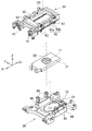
本実施形態に係るスライディングゲート装置1は、図1に示す如く、取鍋やタンディッシュなどの溶鋼容器2に取り付けられる装置である。溶鋼容器2は、鋳造用の高温の溶融金属である溶鋼が収容される例えば鉄板製の容器である。溶鋼容器2の容器内側には、耐火材としてのれんがが配設されている。   The sliding gate apparatus 1 which concerns on this embodiment is an apparatus attached to molten steel containers 2, such as a ladle and a tundish, as shown in FIG. The molten steel container 2 is a container made of, for example, an iron plate in which molten steel that is a high-temperature molten metal for casting is accommodated. On the inner side of the molten steel container 2, a goodwill as a refractory material is disposed.

溶鋼容器2の底部には、貫通孔2aが設けられている。溶鋼容器2の底部には、インサートノズル4が貫通孔2aを貫通するように取り付け固定されている。インサートノズル4は、貫通するノズル孔4aを有している。インサートノズル4は、溶鋼容器2に収容された溶鋼をノズル孔4aを通じて流出・注湯するための注湯用ノズルである。インサートノズル4は、高い耐火性を有する材料(例えば、アルミナやカーボンなど)により形成された、連続鋳造を可能とする部材である。   A through hole 2 a is provided at the bottom of the molten steel container 2. An insert nozzle 4 is attached and fixed to the bottom of the molten steel container 2 so as to penetrate the through hole 2a. The insert nozzle 4 has a nozzle hole 4a that passes therethrough. The insert nozzle 4 is a pouring nozzle for flowing and pouring molten steel accommodated in the molten steel container 2 through the nozzle hole 4a. The insert nozzle 4 is a member that is made of a material having high fire resistance (for example, alumina, carbon, etc.) that enables continuous casting.

スライディングゲート装置1は、インサートノズル4に対応して設けられている。スライディングゲート装置1は、固定プレート10と、スライドプレート11と、を備えている。スライディングゲート装置1は、スライドプレート11が固定プレート10に対してスライド移動されてそれらの貫通孔同士の連通と非連通とを制御することにより、インサートノズル4のノズル孔4aに連通する固定プレート10の貫通孔10aを開閉させてインサートノズル4からの溶鋼の流出を制御する装置である。   The sliding gate device 1 is provided corresponding to the insert nozzle 4. The sliding gate device 1 includes a fixed plate 10 and a slide plate 11. The sliding gate device 1 includes a fixed plate 10 that communicates with the nozzle hole 4 a of the insert nozzle 4 by controlling the communication and non-communication between the through holes by sliding the slide plate 11 with respect to the fixed plate 10. It is an apparatus which controls the outflow of the molten steel from the insert nozzle 4 by opening and closing the through-hole 10a.

固定プレート10及びスライドプレート11はそれぞれ、板状に形成されたれんが部材である。固定プレート10とスライドプレート11とは、互いに上下に重ねられて配置されている。具体的には、固定プレート10は、溶鋼容器2の底部側に配置されていると共に、スライドプレート11は、その固定プレート10に対して下方に隣接して配置されている。スライドプレート11は、固定プレート10に対してその対向面に沿って摺動しながら所定方向X(以下、スライド方向Xと称す。)にスライド移動可能である。スライドプレート11がスライド方向Xにスライド移動すると、固定プレート10の貫通孔10aが開閉されてインサートノズル4のノズル孔4aが開閉される。   Each of the fixed plate 10 and the slide plate 11 is a brick member formed in a plate shape. The fixed plate 10 and the slide plate 11 are arranged so as to overlap each other. Specifically, the fixed plate 10 is disposed on the bottom side of the molten steel container 2, and the slide plate 11 is disposed adjacent to and below the fixed plate 10. The slide plate 11 is slidable in a predetermined direction X (hereinafter referred to as a slide direction X) while sliding along the facing surface with respect to the fixed plate 10. When the slide plate 11 slides in the sliding direction X, the through hole 10a of the fixed plate 10 is opened and closed, and the nozzle hole 4a of the insert nozzle 4 is opened and closed.

固定プレート10は、マウンティングプレート20を介して溶鋼容器2に対して固定されるプレートである。固定プレート10は、マウンティングプレート20ひいては溶鋼容器2に対して着脱可能に取り付けられている。固定プレート10は、溶鋼が流通する貫通孔10aを有している。貫通孔10aは、溶鋼容器2に収容された溶鋼を外部の鋳型などに注湯するために設けられている。貫通孔10aは、インサートノズル4のノズル孔4aの内径とほぼ同じ内径を有している。溶鋼容器2側への固定プレート10の固定は、貫通孔10aがインサートノズル4のノズル孔4aに連通する位置関係が成立するように行われる。尚、固定プレート10は、マウンティングプレート20との接触面に緩衝材としてのクッション材やブリキ板が取り付けられたものであってよい。   The fixed plate 10 is a plate that is fixed to the molten steel container 2 via the mounting plate 20. The fixed plate 10 is detachably attached to the mounting plate 20 and thus the molten steel container 2. The fixed plate 10 has a through hole 10a through which molten steel flows. The through hole 10a is provided for pouring molten steel accommodated in the molten steel container 2 into an external mold or the like. The through hole 10 a has an inner diameter that is substantially the same as the inner diameter of the nozzle hole 4 a of the insert nozzle 4. The fixing plate 10 is fixed to the molten steel container 2 side so that a positional relationship in which the through hole 10a communicates with the nozzle hole 4a of the insert nozzle 4 is established. Note that the fixed plate 10 may be one in which a cushion material or a tin plate as a cushioning material is attached to a contact surface with the mounting plate 20.

スライドプレート11は、固定プレート10ひいては溶鋼容器2に対してスライド移動可能なプレートである。スライドプレート11は、スライド装置30に対して着脱可能に取り付けられている。スライドプレート11は、溶鋼が流通する貫通孔11aを有している。貫通孔11aは、溶鋼容器2に収容された溶鋼を外部の鋳型などに注湯するために設けられている。貫通孔11aは、インサートノズル4のノズル孔4a及び固定プレート10の貫通孔10aの内径とほぼ同じ内径を有している。   The slide plate 11 is a plate that is slidable with respect to the fixed plate 10 and consequently the molten steel container 2. The slide plate 11 is detachably attached to the slide device 30. The slide plate 11 has a through hole 11a through which molten steel flows. The through hole 11a is provided for pouring molten steel accommodated in the molten steel container 2 into an external mold or the like. The through hole 11 a has an inner diameter that is substantially the same as the inner diameter of the nozzle hole 4 a of the insert nozzle 4 and the through hole 10 a of the fixed plate 10.

スライド装置30は、スライドプレート11を固定プレート10ひいては溶鋼容器2に対してスライド移動させる装置である。スライド装置30は、スライドプレート11のスライド移動を、油圧シリンダ或いはモータなどの駆動源を用いて行うものである。スライド装置30によるスライド移動は、スライドプレート11が固定プレート10の対向面に沿って摺動しながらスライド方向Xへ直線的に行われる。   The slide device 30 is a device that slides the slide plate 11 with respect to the fixed plate 10 and thus the molten steel container 2. The slide device 30 performs a sliding movement of the slide plate 11 using a drive source such as a hydraulic cylinder or a motor. The slide movement by the slide device 30 is performed linearly in the slide direction X while the slide plate 11 slides along the opposing surface of the fixed plate 10.

スライド装置30は、スライドプレート11を、図1(A)に示す如くその貫通孔11aを固定プレート10の貫通孔10aに連通させる位置(以下、注湯位置Aと称す。)と、図1(B)に示す如くその貫通孔11aを貫通孔10aに連通させない位置(以下、注湯停止位置Bと称す。)と、の間でスライド移動させることが可能である。以下、注湯位置A及び注湯停止位置Bを含むその注湯位置Aと注湯停止位置Bとの間を適宜、通常スライド範囲と称す。   As shown in FIG. 1A, the slide device 30 has a position (hereinafter referred to as a pouring position A) where the through hole 11a communicates with the through hole 10a of the fixed plate 10, as shown in FIG. As shown in B), the through-hole 11a can be slid between a position where the through-hole 11a does not communicate with the through-hole 10a (hereinafter referred to as a pouring stop position B). Hereinafter, the space between the pouring position A and the pouring stop position B including the pouring position A and the pouring stop position B is appropriately referred to as a normal slide range.

スライドプレート11には、注湯用ノズル5が取り付け固定されている。注湯用ノズル5は、スライドプレート11の、固定プレート10に対向する対向面側とは反対側の背面側に配置されている。注湯用ノズル5は、高い耐火性を有する材料(例えば、アルミナやカーボンなど)により形成された、連続鋳造を可能とする部材である。   A pouring nozzle 5 is attached and fixed to the slide plate 11. The pouring nozzle 5 is disposed on the back side of the slide plate 11 opposite to the facing side facing the fixed plate 10. The pouring nozzle 5 is a member that is made of a material having high fire resistance (for example, alumina, carbon, etc.) and enables continuous casting.

注湯用ノズル5は、溶鋼が流通するノズル孔5aを有している。ノズル孔5aは、インサートノズル4のノズル孔4aなどの内径とほぼ同じ内径を有している。スライドプレート11に対する注湯用ノズル5の固定は、ノズル孔5aがスライドプレート11の貫通孔11aに連通する位置関係が成立するように行われる。   The pouring nozzle 5 has a nozzle hole 5a through which molten steel flows. The nozzle hole 5 a has an inner diameter that is substantially the same as the inner diameter of the nozzle hole 4 a of the insert nozzle 4. The pouring nozzle 5 is fixed to the slide plate 11 so that the positional relationship in which the nozzle hole 5a communicates with the through hole 11a of the slide plate 11 is established.

次に、本実施形態のスライディングゲート装置1における注湯制御を行うための通常動作を説明する。   Next, the normal operation | movement for performing the pouring control in the sliding gate apparatus 1 of this embodiment is demonstrated.

溶鋼が収容された溶鋼容器2からその溶鋼を流出させることによる鋳造が要求されると、スライド装置30がスライドプレート11を注湯位置Aにスライド移動させる。かかる注湯位置Aでは、スライドプレート11の貫通孔11aが、溶鋼容器2の貫通孔2aに挿入されたインサートノズル4のノズル孔4a及び固定プレート10の貫通孔10aに連通される。この場合、ノズル孔4aが開くので、溶鋼容器2に収容された溶鋼は、インサートノズル4のノズル孔4aから固定プレート10の貫通孔10a、スライドプレート11の貫通孔11a、及び注湯用ノズル5のノズル孔5aを介して流出されて注湯される。従って、スライド装置30によりスライドプレート11の貫通孔11aを固定プレート10の貫通孔10aひいてはインサートノズル4のノズル孔4aに連通させることで、溶鋼容器2内の溶鋼を流出させて鋳造を実現することができる。   When casting is required by causing the molten steel to flow out from the molten steel container 2 in which the molten steel is accommodated, the slide device 30 slides the slide plate 11 to the pouring position A. At the pouring position A, the through hole 11 a of the slide plate 11 is communicated with the nozzle hole 4 a of the insert nozzle 4 inserted into the through hole 2 a of the molten steel container 2 and the through hole 10 a of the fixed plate 10. In this case, since the nozzle hole 4a is opened, the molten steel accommodated in the molten steel container 2 flows from the nozzle hole 4a of the insert nozzle 4 to the through hole 10a of the fixed plate 10, the through hole 11a of the slide plate 11, and the pouring nozzle 5. Then, it is poured out through the nozzle hole 5a and poured. Therefore, the slide device 30 allows the through hole 11a of the slide plate 11 to communicate with the through hole 10a of the fixed plate 10 and then the nozzle hole 4a of the insert nozzle 4, thereby causing the molten steel in the molten steel container 2 to flow out and realizing casting. Can do.

また、上記した鋳造の停止が要求されると、スライド装置30がスライドプレート11を注湯位置Aから注湯停止位置Bへスライド移動させる。スライドプレート11が注湯停止位置Bに位置する場合は、スライドプレート11の貫通孔11aが固定プレート10の貫通孔10aに連通されない。この場合、インサートノズル4のノズル孔4aが閉じられるので、溶鋼容器2に収容された溶鋼の流出は停止されて上記の鋳造は停止される。   When the above-described casting stop is requested, the slide device 30 slides the slide plate 11 from the pouring position A to the pouring stop position B. When the slide plate 11 is located at the pouring stop position B, the through hole 11 a of the slide plate 11 is not communicated with the through hole 10 a of the fixed plate 10. In this case, since the nozzle hole 4a of the insert nozzle 4 is closed, the outflow of the molten steel accommodated in the molten steel container 2 is stopped and the above casting is stopped.

次に、図2〜図14を参照して、本実施形態のスライディングゲート装置1が備える面圧負荷解除機構について説明する。   Next, with reference to FIGS. 2 to 14, a surface pressure load releasing mechanism provided in the sliding gate device 1 of the present embodiment will be described.

本実施形態のスライディングゲート装置1は、面圧負荷解除機構40を備えている。面圧負荷解除機構40は、固定プレート10とスライドプレート11との間に面圧を負荷すると共に、その面圧負荷を解除するための機構である。面圧負荷解除機構40は、スライディングゲート装置1の上記通常動作時、すなわち、スライドプレート11が通常スライド範囲内に位置している場合において、固定プレート10とスライドプレート11との間に面圧を負荷する。この両プレート10,11間に負荷される面圧の大きさは、両プレート10,11間からの溶鋼漏れを防止しつつ固定プレート10に対するスライドプレート11の相対移動を許容するように設定されている。   The sliding gate device 1 of this embodiment includes a surface pressure load releasing mechanism 40. The surface pressure load releasing mechanism 40 is a mechanism for applying a surface pressure between the fixed plate 10 and the slide plate 11 and releasing the surface pressure load. The surface pressure load release mechanism 40 applies a surface pressure between the fixed plate 10 and the slide plate 11 during the normal operation of the sliding gate device 1, that is, when the slide plate 11 is positioned within the normal slide range. To load. The magnitude of the surface pressure applied between the plates 10 and 11 is set so as to allow relative movement of the slide plate 11 with respect to the fixed plate 10 while preventing molten steel leakage between the plates 10 and 11. Yes.

スライド装置30は、スライドプレート11を、上記通常スライド範囲を超えてスライド移動させることが可能である。面圧負荷解除機構40は、スライドプレート11がスライド装置30により通常スライド範囲を超えてスライド移動された場合に、上記の面圧負荷を解除することが可能である。以下、この通常スライド範囲外における面圧負荷が解除される位置を面圧解除位置Cと称す。面圧解除位置Cは、図1(C)に示す如く注湯停止位置Bを挟んで注湯位置Aとは反対側の位置に設定されている。   The slide device 30 can slide the slide plate 11 beyond the normal slide range. The surface pressure load release mechanism 40 can release the surface pressure load when the slide plate 11 is slid and moved by the slide device 30 beyond the normal slide range. Hereinafter, the position where the surface pressure load outside the normal slide range is released is referred to as a surface pressure release position C. The surface pressure release position C is set to a position opposite to the pouring position A across the pouring stop position B as shown in FIG.

マウンティングプレート20は、板状に形成されており、溶鋼容器2に取り付け固定されている。尚、溶鋼容器2へのマウンティングプレート20の取り付けは、ボルトやブラケットを用いて行われればよい。図2に示す如く、マウンティングプレート20には、固定プレート10を収納する凹み21が設けられている。マウンティングプレート20は、固定プレート10をその凹み21に収容した状態で保持している。固定プレート10は、凹み21に着脱可能に保持されている。   The mounting plate 20 is formed in a plate shape and is fixed to the molten steel container 2. The mounting plate 20 may be attached to the molten steel container 2 using bolts or brackets. As shown in FIG. 2, the mounting plate 20 is provided with a recess 21 for accommodating the fixed plate 10. The mounting plate 20 holds the fixed plate 10 in a state where it is accommodated in the recess 21. The fixed plate 10 is detachably held in the recess 21.

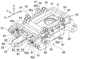
スライド装置30は、図3、図5、図7、図9に示す如く、スライドプレート11を着脱可能に保持するスライダーケース31を有している。スライダーケース31は、箱型に形成されている。スライダーケース31には、スライドプレート11を収納する凹み32が設けられている。スライダーケース31は、スライドプレート11をその凹み32に収容した状態で保持している。スライドプレート11は、凹み32に着脱可能に保持されている。   As shown in FIGS. 3, 5, 7, and 9, the slide device 30 includes a slider case 31 that detachably holds the slide plate 11. The slider case 31 is formed in a box shape. The slider case 31 is provided with a recess 32 for accommodating the slide plate 11. The slider case 31 holds the slide plate 11 in a state where the slide plate 11 is accommodated in the recess 32. The slide plate 11 is detachably held in the recess 32.

スライダーケース31は、ボトムプレート50にスライド方向Xにスライド移動可能に保持されている。スライダーケース31は、シリンダジョイント33を介して駆動源(図示せず)に連結されている。シリンダジョイント33は、スライド方向Xに延びる角棒状の部材である。また、この駆動源は、シリンダジョイント33を介してスライダーケース31をスライド方向Xに往復移動させることが可能である。スライド装置30は、ボトムプレート50においてスライダーケース31をスライド方向Xに移動させることで、そのスライダーケース31に保持されているスライドプレート11を固定プレート10に対して摺動させながらスライド方向Xにスライド移動させる。   The slider case 31 is held on the bottom plate 50 so as to be slidable in the sliding direction X. The slider case 31 is connected to a drive source (not shown) via a cylinder joint 33. The cylinder joint 33 is a rectangular bar-like member that extends in the sliding direction X. Further, this drive source can reciprocate the slider case 31 in the slide direction X via the cylinder joint 33. The slide device 30 slides in the slide direction X while sliding the slide plate 11 held in the slider case 31 with respect to the fixed plate 10 by moving the slider case 31 in the slide direction X on the bottom plate 50. Move.

ボトムプレート50は、略板状或いはフレーム状に形成されている。ボトムプレート50は、マウンティングプレート20に回動可能に支持されている。ボトムプレート50は、一辺側を回動中心にして回動可能である。ボトムプレート50は、ヒンジピン51を中心にしてマウンティングプレート20に対して回動される。ヒンジピン51は、スライド方向Xに直交しかつマウンティングプレート20の板面に対して平行な方向(以下、幅方向Yと称す。)に延びている。尚、ボトムプレート50の回動は、そのボトムプレート50がマウンティングプレート20に対して平行に保たれた状態(いわゆる、閉状態)と略垂直に保たれた状態(いわゆる、開状態)との間で行われるものとしてよい。ボトムプレート50が閉状態にあるとき、スライダーケース31からスライドプレート11を取り出すことはできず、また、ボトムプレート50が開状態にあるとき、スライダーケース31からスライドプレート11を取り出すことは可能である。   The bottom plate 50 is formed in a substantially plate shape or frame shape. The bottom plate 50 is rotatably supported by the mounting plate 20. The bottom plate 50 is rotatable about one side as a rotation center. The bottom plate 50 is rotated with respect to the mounting plate 20 around the hinge pin 51. The hinge pin 51 extends in a direction perpendicular to the sliding direction X and parallel to the plate surface of the mounting plate 20 (hereinafter referred to as the width direction Y). The bottom plate 50 is rotated between a state in which the bottom plate 50 is maintained parallel to the mounting plate 20 (so-called closed state) and a state in which the bottom plate 50 is maintained substantially vertical (so-called open state). It may be performed at. When the bottom plate 50 is in the closed state, the slide plate 11 cannot be removed from the slider case 31, and when the bottom plate 50 is in the open state, the slide plate 11 can be removed from the slider case 31. .

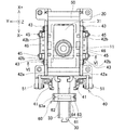
面圧負荷解除機構40は、ボトムプレート50を介してスライダーケース31をマウンティングプレート20側へ押し付けることで、固定プレート10とスライドプレート11との間に面圧を負荷することが可能である。面圧負荷解除機構40は、カムレバー41と、カムプレート42と、第1ローラ43と、スプリング44と、第2ローラ45と、を有している。カムレバー41、カムプレート42、第1ローラ43、スプリング44、及び第2ローラ45は、スライダーケース31がスライド移動されるスライド方向Xに直交する幅方向Yの両側それぞれに設けられており、その幅方向Yにおいて対称に設けられている。   The surface pressure load release mechanism 40 can apply a surface pressure between the fixed plate 10 and the slide plate 11 by pressing the slider case 31 toward the mounting plate 20 via the bottom plate 50. The surface pressure load releasing mechanism 40 includes a cam lever 41, a cam plate 42, a first roller 43, a spring 44, and a second roller 45. The cam lever 41, the cam plate 42, the first roller 43, the spring 44, and the second roller 45 are provided on both sides in the width direction Y orthogonal to the slide direction X in which the slider case 31 is slid and moved. They are provided symmetrically in the direction Y.

カムレバー41は、ボトムプレート50に回動可能に支持され、スライド方向X及び幅方向Yの双方に直交する方向(以下、上下方向Zと称す。)にアーム状に延びる部材である。カムレバー41の回動は、幅方向Yに延びる支持軸を中心にして行われる。カムレバー41は、回動中心を挟んで、上方に延びる第1アーム部41aと、下方に延びる第2アーム部41bと、を有している。   The cam lever 41 is a member that is rotatably supported by the bottom plate 50 and extends in an arm shape in a direction orthogonal to both the sliding direction X and the width direction Y (hereinafter referred to as the vertical direction Z). The cam lever 41 is rotated around a support shaft extending in the width direction Y. The cam lever 41 has a first arm portion 41a extending upward and a second arm portion 41b extending downward with the rotation center interposed therebetween.

カムプレート42は、スライド方向Xに延在する帯状の部材である。カムプレート42は、ボトムプレート50の幅方向Yの側面に配置されている。カムプレート42は、カムレバー41の第1アーム部41aの先端部に連結されている。カムプレート42とカムレバー41とは、カムレバー41がカムプレート42に対して上下方向Zへ移動可能となるように連結されている。カムプレート42は、カムレバー41の回動に伴ってスライド方向Xに移動する。   The cam plate 42 is a band-shaped member extending in the sliding direction X. The cam plate 42 is disposed on the side surface in the width direction Y of the bottom plate 50. The cam plate 42 is connected to the distal end portion of the first arm portion 41 a of the cam lever 41. The cam plate 42 and the cam lever 41 are connected so that the cam lever 41 can move in the vertical direction Z with respect to the cam plate 42. The cam plate 42 moves in the slide direction X as the cam lever 41 rotates.

第1ローラ43は、ボトムプレート50に回転可能に支持されている。第1ローラ43は、ボトムプレート50の幅方向Yの両側それぞれに、上下方向Zにカムプレート42の厚さ分だけ離れて二個一対設けられていると共に、その二個一対がスライド方向Xに所定距離離れて配置されるように二対設けられている。第1ローラ43の回転は、ボトムプレート50の側面に対して幅方向Yに延びる支持軸を中心にして行われる。上記のカムプレート42は、上下方向Zに離れて配置された一対の第1ローラ43の間に挿入されかつスライド方向Xに離れて配置された二対の第1ローラ43それぞれに挿入されることで、それらの第1ローラ43によりスライド方向Xに移動可能に支持されている。   The first roller 43 is rotatably supported by the bottom plate 50. Two pairs of the first rollers 43 are provided on both sides in the width direction Y of the bottom plate 50 so as to be separated in the vertical direction Z by the thickness of the cam plate 42, and the two pairs are arranged in the slide direction X. Two pairs are provided so as to be spaced apart by a predetermined distance. The rotation of the first roller 43 is performed around a support shaft extending in the width direction Y with respect to the side surface of the bottom plate 50. The cam plate 42 is inserted between a pair of first rollers 43 arranged apart in the vertical direction Z and inserted into each of two pairs of first rollers 43 arranged apart in the sliding direction X. The first roller 43 is supported so as to be movable in the slide direction X.

カムプレート42は、プレート本体部42aと、カム部42bと、を有している。プレート本体部42aは、スライド方向Xに延びる帯状の部材であって、断面矩形状に形成されている。カム部42bは、後に詳述する第2ローラ45に接触して係合されることが可能であって、スプリング44に発生させるバネ力を変化させるためのブロック状の部材である。   The cam plate 42 has a plate body portion 42a and a cam portion 42b. The plate main body 42a is a band-shaped member extending in the sliding direction X and is formed in a rectangular cross section. The cam portion 42b is a block-like member that can be brought into contact with and engaged with a second roller 45 that will be described in detail later, and that changes a spring force generated in the spring 44.

カム部42bは、プレート本体部42aの側面に取り付け固定されている。カム部42bは、ボトムプレート50の幅方向Yの両側それぞれに、スライド方向Xに離れて二つ設けられている。カム部42bは、楔状に形成されている。カム部42bは、スライド方向Xに対して平行な水平面42b−1と、スライド方向Xに対して上下方向Zに傾斜する傾斜面42b−2と、を有している。水平面42b−1と傾斜面42b−2とは、スライド方向Xにおいて連続するように形成されている。カム部42bは、プレート本体部42aに対して着脱可能かつ交換可能である。尚、プレート本体部42aへのカム部42bの装着は、例えばボルトを用いて行われればよい。   The cam portion 42b is attached and fixed to the side surface of the plate main body portion 42a. Two cam portions 42 b are provided on both sides of the bottom plate 50 in the width direction Y, separated in the slide direction X. The cam portion 42b is formed in a wedge shape. The cam portion 42 b includes a horizontal plane 42 b-1 that is parallel to the slide direction X and an inclined surface 42 b-2 that is inclined in the vertical direction Z with respect to the slide direction X. The horizontal surface 42b-1 and the inclined surface 42b-2 are formed so as to be continuous in the sliding direction X. The cam portion 42b is detachable and replaceable with respect to the plate body portion 42a. The cam portion 42b may be attached to the plate main body portion 42a using, for example, a bolt.

スプリング44は、固定プレート10とスライドプレート11との間に面圧を負荷するためのバネ力を発生し得るバネ部材(弾性体)である。スプリング44は、バネ力を上下方向Zに発生する。スプリング44は、図4、図6、図8、及び図10に示す如く、スプリングボックス46に収容されている。スプリングボックス46は、複数のスプリング44を並列に収容できるように箱状に形成されている。スプリング44は、スプリングボックス46内で複数が並列に並ぶように配置されており、所望のバネ力を発生し得る。   The spring 44 is a spring member (elastic body) that can generate a spring force for applying a surface pressure between the fixed plate 10 and the slide plate 11. The spring 44 generates a spring force in the vertical direction Z. As shown in FIGS. 4, 6, 8, and 10, the spring 44 is accommodated in a spring box 46. The spring box 46 is formed in a box shape so that a plurality of springs 44 can be accommodated in parallel. A plurality of the springs 44 are arranged in parallel in the spring box 46 and can generate a desired spring force.

スプリングボックス46は、スプリング44の一端が固定される固定部46aと、スプリング44の他端が固定される板状の可動部46bと、を有している。固定部46aは、マウンティングプレート20に固定され或いはマウンティングプレート20に一体形成された部位である。可動部46bは、固定部46aに対して、スプリング44が伸縮する上下方向Zに変位することが可能な部材である。固定部46aと可動部46bとの間には、スプリング44の発生するバネ力が作用する。   The spring box 46 has a fixed portion 46 a to which one end of the spring 44 is fixed, and a plate-like movable portion 46 b to which the other end of the spring 44 is fixed. The fixing part 46 a is a part fixed to the mounting plate 20 or integrally formed with the mounting plate 20. The movable part 46b is a member that can be displaced in the vertical direction Z in which the spring 44 expands and contracts with respect to the fixed part 46a. A spring force generated by the spring 44 acts between the fixed portion 46a and the movable portion 46b.

可動部46bには、支持バー47を介して第2ローラ45が連結されている。支持バー47は、スライド方向Xの両端に一つずつ設けられている。支持バー47は、スライド方向Xの端位置にあるスプリング44の中心を通って固定部46aを貫通して上下方向Zに延在する略棒状の部材である。支持バー47は、一端側で可動部46bに締結されており、その一端とは反対側の他端側で第2ローラ45に連結されている。   A second roller 45 is connected to the movable portion 46 b via a support bar 47. One support bar 47 is provided at each end of the slide direction X. The support bar 47 is a substantially bar-shaped member that extends in the up-down direction Z through the center of the spring 44 at the end position in the slide direction X, through the fixing portion 46a. The support bar 47 is fastened to the movable portion 46b at one end side, and is connected to the second roller 45 at the other end side opposite to the one end.

第2ローラ45は、支持バー47の他端側に回転可能に支持されている。第2ローラ45は、可動部46bと一体で上下方向Zに変位することが可能である。第2ローラ45は、円形の回転体である。第2ローラ45は、ボトムプレート50の幅方向Yの両側それぞれに、カム部42bに対応して、スライド方向Xに所定距離離れて二つ設けられている。第2ローラ45の回転は、ボトムプレート50の側面にて幅方向Yに延びる支持軸を中心にして行われる。   The second roller 45 is rotatably supported on the other end side of the support bar 47. The second roller 45 can be displaced in the vertical direction Z integrally with the movable portion 46b. The second roller 45 is a circular rotating body. Two second rollers 45 are provided on both sides of the bottom plate 50 in the width direction Y at a predetermined distance in the slide direction X, corresponding to the cam portions 42b. The rotation of the second roller 45 is performed around the support shaft extending in the width direction Y on the side surface of the bottom plate 50.

第2ローラ45は、カムプレート42のカム部42bに接触して係合することが可能である。第2ローラ45とカム部42bとが係合する状態は、後に詳述する如く、マウンティングプレート20に対するスライダーケース31のスライド方向Xの位置すなわち固定プレート10に対するカムプレート42ひいてはスライドプレート11のスライド位置に応じて変化する。第2ローラ45は、その下部で、傾斜面42b−2に接することが可能であると共に、水平面42b−1に係合することが可能である。   The second roller 45 can be brought into contact with and engaged with the cam portion 42 b of the cam plate 42. The state in which the second roller 45 and the cam portion 42b are engaged with each other is the position in the sliding direction X of the slider case 31 with respect to the mounting plate 20, that is, the sliding position of the cam plate 42 and thus the slide plate 11 with respect to the fixed plate 10, as will be described in detail later. It changes according to. The second roller 45 can contact the inclined surface 42b-2 at the lower portion thereof and can engage the horizontal surface 42b-1.

スライドプレート11が面圧解除位置Cに位置する場合は、第2ローラ45が傾斜面42b−2に接触せず、水平面42b−1にも係合しない。この場合、スプリング44の発生するバネ力はほぼゼロであり、そのスプリング44からカム部42bに伝達されるバネ力はほぼゼロであるので、面圧負荷解除機構40により固定プレート10とスライドプレート11との間に負荷される面圧はほぼゼロである。   When the slide plate 11 is located at the surface pressure release position C, the second roller 45 does not contact the inclined surface 42b-2 and does not engage with the horizontal surface 42b-1. In this case, the spring force generated by the spring 44 is almost zero, and the spring force transmitted from the spring 44 to the cam portion 42b is almost zero. Therefore, the surface pressure load releasing mechanism 40 causes the fixed plate 10 and the slide plate 11 to move. The surface pressure applied between and is almost zero.

スライドプレート11が上記の面圧解除位置Cから注湯停止位置Bへスライドする過程で、第2ローラ45が傾斜面42b−2に接触する。この場合は、そのスライド過程でスプリング44の発生するバネ力が徐々に大きくなり、そのスプリング44からカム部42bに伝達されるバネ力が徐々に大きくなるので、面圧負荷解除機構40により固定プレート10とスライドプレート11との間に負荷される面圧が徐々に増大する。   In the process in which the slide plate 11 slides from the surface pressure release position C to the pouring stop position B, the second roller 45 contacts the inclined surface 42b-2. In this case, the spring force generated by the spring 44 gradually increases during the sliding process, and the spring force transmitted from the spring 44 to the cam portion 42b gradually increases. The surface pressure applied between 10 and the slide plate 11 gradually increases.

そして、スライドプレート11がその通常スライド範囲内に位置する場合は、第2ローラ45が水平面42b−1に接触して係合する。この場合、スプリング44の発生するバネ力は最大となり、面圧負荷解除機構40により固定プレート10とスライドプレート11との間に負荷される面圧は最大となる。   And when the slide plate 11 is located in the normal slide range, the 2nd roller 45 contacts and engages with the horizontal surface 42b-1. In this case, the spring force generated by the spring 44 is maximized, and the surface pressure applied between the fixed plate 10 and the slide plate 11 by the surface pressure load releasing mechanism 40 is maximized.

面圧負荷解除機構40は、固定プレート10とスライドプレート11との間の面圧負荷を解除させるための解除用治具60を備えている。解除用治具60は、スライド装置30に着脱可能に取り付けられる。面圧負荷解除機構40は、解除用治具60がスライド装置30に装着されている場合に面圧負荷を解除することが可能である。   The surface pressure load releasing mechanism 40 includes a release jig 60 for releasing the surface pressure load between the fixed plate 10 and the slide plate 11. The release jig 60 is detachably attached to the slide device 30. The surface pressure load release mechanism 40 can release the surface pressure load when the release jig 60 is mounted on the slide device 30.

解除用治具60は、レバー押引部材61を有している。レバー押引部材61は、シリンダジョイント33に取り付け固定され得る部材であって、シリンダジョイント33に取り付け固定された状態で上記したカムレバー41の第2アーム部41bをスライド方向Xに押し引きしてそのカムレバー41を回動させる部材である。尚、レバー押引部材61は、例えばシリンダジョイント33への取り付け容易性を確保すべく、複数の部位に分割され、それら複数の部位がボルト締結などで互いに一体化されたものであってもよい。   The release jig 60 has a lever push / pull member 61. The lever push / pull member 61 is a member that can be attached and fixed to the cylinder joint 33. In the state where the lever push / pull member 61 is attached and fixed to the cylinder joint 33, the second arm portion 41b of the cam lever 41 is pushed and pulled in the slide direction X. A member that rotates the cam lever 41. The lever pushing / pulling member 61 may be divided into a plurality of parts, for example, in order to ensure ease of attachment to the cylinder joint 33, and these parts may be integrated with each other by bolt fastening or the like. .

レバー押引部材61は、シリンダジョイント33に対して着脱可能或いは少なくともスライド方向Xに移動可能である。レバー押引部材61は、シリンダジョイント33の外周側を取り囲みつつ断面における一辺の中央部にて切り欠かれた形状に形成されている。すなわち、レバー押引部材61は、幅方向Yの両端部それぞれにブロック状に設けられたブロック部63と、幅方向Yに延在し、それらのブロック部63同士を繋ぐ連結部64と、を有している。   The lever push / pull member 61 can be attached to and detached from the cylinder joint 33 or can be moved at least in the slide direction X. The lever push / pull member 61 is formed in a shape that is cut out at the center of one side of the cross section while surrounding the outer periphery of the cylinder joint 33. That is, the lever push / pull member 61 includes a block portion 63 provided in a block shape at each end portion in the width direction Y, and a connecting portion 64 that extends in the width direction Y and connects the block portions 63 to each other. Have.

ブロック部63は、シリンダジョイント33の側方(幅方向Y)に設けられている。ブロック部63は、シリンダジョイント33に取り付け固定された際に、カムレバー41の、カムプレート42が連結された第1アーム部41aとは回動中心を挟んで反対側の第2アーム部41bの先端が当接し得る位置に配置される。   The block part 63 is provided on the side (width direction Y) of the cylinder joint 33. When the block portion 63 is attached and fixed to the cylinder joint 33, the tip of the second arm portion 41b opposite to the first arm portion 41a of the cam lever 41 with respect to the first arm portion 41a to which the cam plate 42 is connected. Are arranged at positions where they can abut.

ブロック部63には、溝63aが形成されている。溝63aは、スライドプレート11の通常スライド範囲外においてカムレバー41の第2アーム部41bの先端が嵌ることができる形状に形成されている。ブロック部63は、スライド装置30によりスライドプレート11が通常スライド範囲を超えてスライド方向Xにスライド移動された際にその溝63aにカムレバー41の第2アーム部41bの先端が嵌ることで、そのカムレバー41の第2アーム部41bの先端に、スライド方向Xに押圧して回動中心を中心にして回動させる力を付与することが可能である。   A groove 63 a is formed in the block portion 63. The groove 63a is formed in a shape that can fit the tip of the second arm portion 41b of the cam lever 41 outside the normal sliding range of the slide plate 11. When the slide plate 11 is slid and moved in the slide direction X beyond the normal slide range by the slide device 30, the block portion 63 is fitted with the tip of the second arm portion 41 b of the cam lever 41 in the groove 63 a, so that the cam lever It is possible to apply a force for rotating around the rotation center by pressing in the slide direction X to the tip of the second arm portion 41b of 41.

スライド装置30によりスライドプレート11が通常スライド範囲内に位置しているときは、ブロック部63の溝63aにカムレバー41の第2アーム部41bの先端が嵌らないので、カムレバー41には、ブロック部63から回動させる力が付与されない。この場合、カムレバー41は、カムプレート42のカム部42bが第2ローラ45に係合される回動位置に維持される。   When the slide plate 11 is positioned within the normal slide range by the slide device 30, the tip of the second arm portion 41 b of the cam lever 41 does not fit into the groove 63 a of the block portion 63. No force to rotate from 63 is applied. In this case, the cam lever 41 is maintained at a rotational position where the cam portion 42 b of the cam plate 42 is engaged with the second roller 45.

一方、スライド装置30がスライドプレート11を通常スライド範囲内からその通常スライド範囲を超えてスライド方向X(具体的には、スライド方向X+)にスライド移動させると、ブロック部63の溝63aにカムレバー41の第2アーム部41bの先端が嵌るので、スライド装置30によるスライドプレート11のスライド移動に伴ってカムレバー41にブロック部63から回動させる力が付与される。この場合、カムレバー41は、カム部42bと第2ローラ45との係合を解除させる方向(図4及び図8において左回り方向)に回動され、カムプレート42をボトムプレート50に対してスライド方向X(具体的には、スライド方向X−)に移動させる。   On the other hand, when the slide device 30 slides the slide plate 11 from the normal slide range to beyond the normal slide range in the slide direction X (specifically, the slide direction X +), the cam lever 41 is inserted into the groove 63a of the block portion 63. Since the tip of the second arm portion 41 b is fitted, a force for rotating the cam lever 41 from the block portion 63 is applied as the slide plate 11 slides by the slide device 30. In this case, the cam lever 41 is rotated in a direction for releasing the engagement between the cam portion 42 b and the second roller 45 (counterclockwise in FIGS. 4 and 8), and the cam plate 42 slides with respect to the bottom plate 50. It is moved in the direction X (specifically, the sliding direction X−).

図12に示す如く、レバー押引部材61の連結部64には、貫通孔64aが設けられている。貫通孔64aは、連結部64の幅方向Yの中央部に設けられており、その連結部64を上下方向Zに貫通している。貫通孔64aは、後述の固定用取付部材62が挿入されることが可能な形状に形成されている。また、シリンダジョイント33の、連結部64に対向する上面には、凹部33aが形成されている。凹部33aは、固定用取付部材62に対応した形状に形成されており、固定用取付部材62が嵌ることが可能である。凹部33aは、貫通孔64aに連通可能な位置に設けられている。   As shown in FIG. 12, the connecting portion 64 of the lever pushing / pulling member 61 is provided with a through hole 64a. The through hole 64 a is provided at the center of the connecting portion 64 in the width direction Y, and penetrates the connecting portion 64 in the vertical direction Z. The through hole 64a is formed in a shape into which a fixing attachment member 62 described later can be inserted. A recess 33 a is formed on the upper surface of the cylinder joint 33 that faces the connecting portion 64. The recess 33a is formed in a shape corresponding to the fixing attachment member 62, and the fixing attachment member 62 can be fitted therein. The recess 33a is provided at a position where it can communicate with the through hole 64a.

図11に示す如く、固定用取付部材62は、レバー押引部材61の連結部64の貫通孔64a及びシリンダジョイント33の凹部33aに嵌合可能なブロック状に形成されている。固定用取付部材62は、作業者が持ち運び可能に取手部62aを有している。固定用取付部材62は、レバー押引部材61の連結部64及びシリンダジョイント33に対して着脱可能である。   As shown in FIG. 11, the fixing attachment member 62 is formed in a block shape that can be fitted into the through hole 64 a of the connecting portion 64 of the lever pushing member 61 and the concave portion 33 a of the cylinder joint 33. The fixing attachment member 62 has a handle portion 62a so that an operator can carry it. The fixing attachment member 62 can be attached to and detached from the connecting portion 64 of the lever push / pull member 61 and the cylinder joint 33.

固定用取付部材62は、レバー押引部材61の連結部64の貫通孔64aとシリンダジョイント33の凹部33aとが互いに連通した状態で、それらの貫通孔64a及び凹部33aに嵌合して装着される。固定用取付部材62は、貫通孔64a及び凹部33aの双方に嵌合した場合に、レバー押引部材61とシリンダジョイント33との間に介在することで、レバー押引部材61をシリンダジョイント33に固定する。すなわち、レバー押引部材61は、固定用取付部材62が連結部64の貫通孔64a及びシリンダジョイント33の凹部33aに嵌合している場合に、シリンダジョイント33に対してスライド方向Xへの移動不能に固定される。この状態でスライド装置30がスライドプレート11を通常スライド範囲を超えてスライド方向Xにスライド移動させると、ブロック部63にてカムレバー41の第2アーム部41bへの回動させる力の付与が可能となる。   The fixing mounting member 62 is fitted and fitted into the through hole 64a and the recess 33a in a state where the through hole 64a of the connecting portion 64 of the lever push / pull member 61 and the recess 33a of the cylinder joint 33 communicate with each other. The When the fixing mounting member 62 is fitted in both the through hole 64a and the recess 33a, the fixing mounting member 62 is interposed between the lever pressing member 61 and the cylinder joint 33 so that the lever pressing member 61 is attached to the cylinder joint 33. Fix it. That is, the lever push / pull member 61 moves in the sliding direction X with respect to the cylinder joint 33 when the fixing mounting member 62 is fitted in the through hole 64a of the connecting portion 64 and the concave portion 33a of the cylinder joint 33. Fixed to impossible. When the slide device 30 slides the slide plate 11 in the slide direction X beyond the normal slide range in this state, it is possible to apply a force for rotating the cam lever 41 to the second arm portion 41b by the block portion 63. Become.

次に、本実施形態のスライディングゲート装置1が備える面圧負荷解除機構40の動作について説明する。   Next, operation | movement of the surface pressure load cancellation | release mechanism 40 with which the sliding gate apparatus 1 of this embodiment is provided is demonstrated.

スライディングゲート装置1の通常動作は、解除用治具60の固定用取付部材62がレバー押引部材61の貫通孔64aに嵌合せず或いはシリンダジョイント33の凹部33aに嵌合しない状態、すなわち、レバー押引部材61がシリンダジョイント33に固定されない状態で実現される。この状態では、スライド装置30がスライドプレート11をスライド方向Xにスライド移動させても、そのレバー押引部材61がカムレバー41を回動させる力をそのカムレバー41に付与することができないので、図13に示す如く、カムレバー41がカムプレート42のカム部42bと第2ローラ45とが係合される回動位置に維持される。   The normal operation of the sliding gate device 1 is that the fixing mounting member 62 of the releasing jig 60 does not fit into the through hole 64a of the lever push / pull member 61 or the recessed portion 33a of the cylinder joint 33, that is, the lever. This is realized in a state where the push / pull member 61 is not fixed to the cylinder joint 33. In this state, even if the slide device 30 slides the slide plate 11 in the slide direction X, the lever push / pull member 61 cannot apply the force to rotate the cam lever 41 to the cam lever 41. As shown in FIG. 4, the cam lever 41 is maintained at the rotational position where the cam portion 42b of the cam plate 42 and the second roller 45 are engaged.

カム部42bと第2ローラ45とが係合されていると、スプリングボックス46の可動部46bが、固定部46aに対して接近する方向(すなわち、上下方向Zのうちスプリング44を収縮させる一方向)に変位するように持ち上がる。このため、固定部46aと可動部46bとの間にスプリング44による大きなバネ力が発生するので、固定プレート10とスライドプレート11との間に面圧が負荷される。従って、この場合、面圧負荷解除機構40は、固定プレート10とスライドプレート11との間に面圧を負荷する。   When the cam portion 42b and the second roller 45 are engaged, the movable portion 46b of the spring box 46 approaches the fixed portion 46a (that is, one direction in which the spring 44 contracts in the vertical direction Z). ) Lifts up to displace. For this reason, since a large spring force is generated by the spring 44 between the fixed portion 46 a and the movable portion 46 b, a surface pressure is applied between the fixed plate 10 and the slide plate 11. Therefore, in this case, the surface pressure load releasing mechanism 40 applies a surface pressure between the fixed plate 10 and the slide plate 11.

次に、上記の如く固定プレート10とスライドプレート11との間に面圧が負荷された通常動作状態において例えば固定プレート10及びスライドプレート11の交換が要求されると、そのプレート交換を実現するために、面圧負荷解除機構40による面圧負荷を解除することが必要となる。面圧負荷解除機構40による面圧負荷の解除は、以下の手順に従って行われる。   Next, in the normal operation state in which the surface pressure is applied between the fixed plate 10 and the slide plate 11 as described above, for example, when the replacement of the fixed plate 10 and the slide plate 11 is required, the plate replacement is realized. In addition, it is necessary to release the surface pressure load by the surface pressure load releasing mechanism 40. Release of the surface pressure load by the surface pressure load release mechanism 40 is performed according to the following procedure.

具体的には例えば、上記の交換要求後、まず、作業者の手動操作により解除用治具60の固定用取付部材62がレバー押引部材61の貫通孔64a及びシリンダジョイント33の凹部33aの双方に嵌合される。固定用取付部材62がレバー押引部材61の貫通孔64a及びシリンダジョイント33の凹部33aに嵌合されている状態では、レバー押引部材61がシリンダジョイント33に固定される。次に、スライド装置30がスライドプレート11を通常スライド範囲内からその通常スライド範囲を超えて面圧解除位置Cまでスライド方向X+にスライド移動させる。スライドプレート11が通常スライド範囲を超えてスライド方向X+にスライド移動されると、そのレバー押引部材61がカムレバー41を回動させる力をそのカムレバー41に付与する。   Specifically, for example, after the above replacement request, first, the fixing mounting member 62 of the release jig 60 is manually moved by both the through hole 64a of the lever push / pull member 61 and the recess 33a of the cylinder joint 33 by the operator's manual operation. Fitted. In a state where the fixing mounting member 62 is fitted in the through hole 64 a of the lever pushing member 61 and the recess 33 a of the cylinder joint 33, the lever pushing member 61 is fixed to the cylinder joint 33. Next, the slide device 30 slides the slide plate 11 in the slide direction X + from the normal slide range to the surface pressure release position C beyond the normal slide range. When the slide plate 11 is slid and moved in the slide direction X + beyond the normal slide range, the lever pushing / pulling member 61 applies a force for rotating the cam lever 41 to the cam lever 41.

この状態では、図14に示す如く、カムレバー41が、回動中心を中心にしてカム部42bと第2ローラ45との係合を解除させる方向に回動され、カムプレート42をスライド方向X−に移動させる。このカムレバー41の回動によりカムプレート42がスライド方向X−に移動されると、カム部42b(具体的には、水平面42b−1)と第2ローラ45との係合が解除されて、スプリングボックス46の可動部46bが、固定部46aに対して離間する方向(すなわち、上下方向Zのうちスプリング44を伸張させる他方向)に変位するように押し下がる。このため、固定部46aと可動部46bとの間に発生するスプリング44のバネ力が小さくなり、固定プレート10とスライドプレート11との間の面圧負荷が解除される。従って、この場合、面圧負荷解除機構40は、固定プレート10とスライドプレート11との間の面圧負荷を解除する。   In this state, as shown in FIG. 14, the cam lever 41 is rotated about the rotation center in a direction for releasing the engagement between the cam portion 42b and the second roller 45, and the cam plate 42 is moved in the sliding direction X−. Move to. When the cam plate 42 is moved in the slide direction X- by the rotation of the cam lever 41, the engagement between the cam portion 42b (specifically, the horizontal surface 42b-1) and the second roller 45 is released, and the spring The movable part 46b of the box 46 is pushed down so as to be displaced in a direction away from the fixed part 46a (that is, the other direction in which the spring 44 is extended in the vertical direction Z). For this reason, the spring force of the spring 44 generated between the fixed portion 46a and the movable portion 46b is reduced, and the surface pressure load between the fixed plate 10 and the slide plate 11 is released. Therefore, in this case, the surface pressure load releasing mechanism 40 releases the surface pressure load between the fixed plate 10 and the slide plate 11.

マウンティングプレート20に対するボトムプレート50の、ヒンジピン51を中心にした回動は、面圧負荷解除機構40により固定プレート10とスライドプレート11との間の面圧負荷が解除されている状態で許可され、その面圧が負荷されている状態では禁止される。この面圧負荷が解除されている状態でマウンティングプレート20に対してボトムプレート50が作業者の手動操作により回動されると、ボトムプレート50が開状態となる。この場合、ボトムプレート50とマウンティングプレート20とが大きく離間するので、スライダーケース31のスライドプレート11、及び、マウンティングプレート20に保持されている固定プレート10の脱着が可能となり、それらのプレート10,11の交換が可能となる。   The rotation of the bottom plate 50 with respect to the mounting plate 20 around the hinge pin 51 is permitted in a state where the surface pressure load between the fixed plate 10 and the slide plate 11 is released by the surface pressure load release mechanism 40. It is prohibited when the surface pressure is applied. When the bottom plate 50 is rotated by the operator's manual operation with respect to the mounting plate 20 in a state where the surface pressure load is released, the bottom plate 50 is opened. In this case, since the bottom plate 50 and the mounting plate 20 are largely separated from each other, the slide plate 11 of the slider case 31 and the fixed plate 10 held by the mounting plate 20 can be attached and detached. Can be exchanged.

そして、上記の如くプレート10,11の交換が行われた後は、上記の手順とは逆の手順で固定プレート10とスライドプレート11との間に面圧が負荷される。具体的には、プレート10,11の交換後、ボトムプレート50がマウンティングプレート20に対して開状態から閉状態へ向けて回動され、その後、スライド装置30がスライドプレート11を通常スライド範囲内までスライド方向X−にスライド移動させる。このスライド移動が行われると、解除用治具60のブロック部63がシリンダジョイント33と一緒にスライド方向X−に移動されるので、そのブロック部63の移動により、カムレバー41がカム部42bと第2ローラ45とを係合させる方向に回動され、その係合後、ブロック部63の溝63aへのカムレバー41の第2アーム部41bの嵌合が解除される。この場合、カムプレート42のスライド方向X+への移動によりカム部42bと第2ローラ45とが係合されるので、スプリング44のバネ力により固定プレート10とスライドプレート11との間に面圧が負荷される。   After the plates 10 and 11 are exchanged as described above, a surface pressure is applied between the fixed plate 10 and the slide plate 11 by a procedure reverse to the above procedure. Specifically, after the exchange of the plates 10 and 11, the bottom plate 50 is rotated from the open state to the closed state with respect to the mounting plate 20, and then the slide device 30 moves the slide plate 11 to the normal slide range. Slide and move in the sliding direction X-. When this sliding movement is performed, the block portion 63 of the releasing jig 60 is moved together with the cylinder joint 33 in the sliding direction X-, so that the cam lever 41 is moved away from the cam portion 42b by the movement of the block portion 63. The second roller 45 is rotated in the direction in which the second roller 45 is engaged. After the engagement, the fitting of the second arm portion 41 b of the cam lever 41 to the groove 63 a of the block portion 63 is released. In this case, since the cam portion 42b and the second roller 45 are engaged by the movement of the cam plate 42 in the sliding direction X +, the surface pressure is applied between the fixed plate 10 and the slide plate 11 by the spring force of the spring 44. Be loaded.

このように、本実施形態のスライディングゲート装置1においては、スライドプレート11が注湯位置Aと注湯停止位置Bとの間の通常スライド範囲内に位置している場合、面圧負荷解除機構40が固定プレート10とスライドプレート11との間に面圧を負荷する。一方、スライドプレート11が上記の通常スライド範囲外の面圧解除位置Cに位置している場合、面圧負荷解除機構40がその面圧負荷を解除する。   As described above, in the sliding gate device 1 of the present embodiment, when the slide plate 11 is located within the normal slide range between the pouring position A and the pouring stop position B, the surface pressure load releasing mechanism 40 is used. Applies a surface pressure between the fixed plate 10 and the slide plate 11. On the other hand, when the slide plate 11 is located at the surface pressure release position C outside the normal slide range, the surface pressure load release mechanism 40 releases the surface pressure load.

すなわち、スライド装置30によるスライダーケースのスライド移動が通常スライド範囲内で行われている場合すなわち溶鋼容器2のインサートノズル4のノズル孔4aが開閉制御される場合、面圧負荷解除機構40は、上記の面圧負荷を行う。一方、スライド装置30に着脱可能な解除用治具60がそのスライド装置30のシリンダジョイント33に装着固定されている状態で、スライド装置30によるスライダーケース31のスライド移動が通常スライド範囲を超えて行われた場合、面圧負荷解除機構40は、その面圧負荷を解除する。   That is, when the slide movement of the slider case by the slide device 30 is performed within the normal slide range, that is, when the nozzle hole 4a of the insert nozzle 4 of the molten steel container 2 is controlled to open and close, the surface pressure load release mechanism 40 is The surface pressure load is performed. On the other hand, in a state where the release jig 60 that can be attached to and detached from the slide device 30 is attached and fixed to the cylinder joint 33 of the slide device 30, the slide movement of the slider case 31 by the slide device 30 is performed beyond the normal slide range. If it is broken, the surface pressure load releasing mechanism 40 releases the surface pressure load.

従って、固定プレート10とスライドプレート11との間に面圧が負荷された状態でそのスライドプレート11が通常スライド範囲内においてスライド移動されるインサートノズル4のノズル孔4aの開閉制御と、その面圧負荷の解除制御と、を同じスライド装置30によるスライド方向Xへのスライド移動により実現することができ、一つのスライド装置30によるスライド移動のみで実現することができる。このため、上記したノズル開閉制御及び面圧負荷解除制御の双方を実現するうえでの全体構成を簡素化することができる。   Accordingly, the opening / closing control of the nozzle hole 4a of the insert nozzle 4 in which the slide plate 11 is slid and moved within the normal slide range with the surface pressure applied between the fixed plate 10 and the slide plate 11, and the surface pressure. The load release control can be realized by the sliding movement in the sliding direction X by the same sliding device 30, and can be realized only by the sliding movement by one sliding device 30. For this reason, the entire configuration for realizing both the nozzle opening / closing control and the surface pressure load release control can be simplified.

また、面圧負荷解除機構40による面圧負荷の解除は、解除用治具60がスライド装置30のシリンダジョイント33に装着固定されていなければ実現されない。すなわち、シリンダジョイント33に解除用治具60が装着固定されており、かつ、スライド装置30によるスライドプレート11のスライド移動が通常スライド範囲を超えて面圧解除位置Cに達した場合に、その解除用治具60が面圧負荷解除機構40のカムレバー41を面圧を解除させる方向へ回動させる。カムレバー41が面圧解除方向に回動されると、スプリング44のバネ力が消滅し、固定プレート10とスライドプレート11との間の面圧負荷が解除される。   Further, the release of the surface pressure load by the surface pressure load release mechanism 40 is not realized unless the release jig 60 is attached and fixed to the cylinder joint 33 of the slide device 30. That is, when the release jig 60 is fixedly attached to the cylinder joint 33 and the slide movement of the slide plate 11 by the slide device 30 exceeds the normal slide range and reaches the surface pressure release position C, the release is performed. The jig 60 rotates the cam lever 41 of the surface pressure load releasing mechanism 40 in a direction to release the surface pressure. When the cam lever 41 is rotated in the surface pressure release direction, the spring force of the spring 44 disappears, and the surface pressure load between the fixed plate 10 and the slide plate 11 is released.

一方、固定プレート10とスライドプレート11との間に面圧が負荷される上記ノズル開閉制御中は、シリンダジョイント33に解除用治具60が装着固定されない。解除用治具60がシリンダジョイント33に装着固定されていないときは、面圧負荷解除機構40のカムレバー41が面圧解除方向に回動されない。この場合は、スプリング44のバネ力が維持されるので、固定プレート10とスライドプレート11との間に面圧が負荷される状態が維持され、その面圧負荷の解除は回避される。   On the other hand, during the nozzle opening / closing control in which the surface pressure is applied between the fixed plate 10 and the slide plate 11, the release jig 60 is not attached and fixed to the cylinder joint 33. When the releasing jig 60 is not attached and fixed to the cylinder joint 33, the cam lever 41 of the surface pressure load releasing mechanism 40 is not rotated in the surface pressure releasing direction. In this case, since the spring force of the spring 44 is maintained, a state in which a surface pressure is applied between the fixed plate 10 and the slide plate 11 is maintained, and release of the surface pressure load is avoided.

更に、上記ノズル開閉制御中は、スライド装置30によるスライドプレート11のスライド移動が通常スライド範囲内に制限されるので、仮にシリンダジョイント33に解除用治具60が装着固定されていたとしても、その解除用治具60が面圧負荷解除機構40のカムレバー41を面圧解除方向に回動させることは無い。この場合も、スプリング44のバネ力が維持されるので、固定プレート10とスライドプレート11との間に面圧が負荷される状態が維持され、その面圧負荷の解除は回避される。   Further, during the nozzle opening / closing control, the slide movement of the slide plate 11 by the slide device 30 is normally limited within the slide range, so even if the release jig 60 is mounted and fixed to the cylinder joint 33, The releasing jig 60 does not rotate the cam lever 41 of the surface pressure load releasing mechanism 40 in the surface pressure releasing direction. Also in this case, since the spring force of the spring 44 is maintained, a state in which a surface pressure is applied between the fixed plate 10 and the slide plate 11 is maintained, and release of the surface pressure load is avoided.

従って、溶鋼容器2のインサートノズル4のノズル孔4aの開閉制御中は、スライドプレート11のスライド移動が通常スライド範囲内に制限されること又は解除用治具60がスライド装置30から取り外されていることで、その開閉制御中に面圧負荷解除機構40により固定プレート10とスライドプレート11との間の面圧負荷が解除されるのを確実に回避することができる。   Therefore, during the opening / closing control of the nozzle hole 4 a of the insert nozzle 4 of the molten steel container 2, the slide movement of the slide plate 11 is restricted within the normal slide range or the release jig 60 is removed from the slide device 30. Thus, it is possible to reliably avoid the release of the surface pressure load between the fixed plate 10 and the slide plate 11 by the surface pressure load releasing mechanism 40 during the opening / closing control.

この点、本実施形態のスライディングゲート装置1によれば、固定プレート10とスライドプレート11との面圧負荷状態でのインサートノズル4のノズル孔4aの開閉制御と、面圧負荷の解除制御と、を同じスライド装置30によるスライド移動により実現しつつ、そのノズル孔4aの開閉制御中にその面圧負荷が解除されるのを確実に回避することができる。   In this respect, according to the sliding gate device 1 of the present embodiment, the opening / closing control of the nozzle hole 4a of the insert nozzle 4 in the surface pressure load state between the fixed plate 10 and the slide plate 11, the control of releasing the surface pressure load, Can be reliably prevented from being released during the opening / closing control of the nozzle hole 4a.

スライディングゲート装置1において、面圧負荷解除機構40により固定プレート10とスライドプレート11との間の面圧負荷を解除させるうえでは、解除用治具60がスライド装置30のシリンダジョイント33に装着固定されていること、具体的には、作業者の手作業で固定用取付部材62がレバー押引部材61の貫通孔61a及びシリンダジョイント33の凹部33aに嵌合されていることが必要である。面圧負荷解除機構40による上記の面圧負荷とその解除とを切り替えるうえでは、作業者は、解除用治具60をスライド装置30に装着固定させ或いはその装着固定されている解除用治具60を取り外す作業を行えば十分である。また、上記の面圧負荷とその解除とを切り替えるうえでは、ブロック状の固定用取付部材62とは別途の面圧負荷/解除用ツールなどをスライディングゲート装置1に取り付けることは不要である。このため、面圧負荷解除機構40を構成するうえで、コスト低減及び作業負荷の低減が図られている。   In the sliding gate device 1, in order to release the surface pressure load between the fixed plate 10 and the slide plate 11 by the surface pressure load release mechanism 40, the release jig 60 is mounted and fixed to the cylinder joint 33 of the slide device 30. Specifically, it is necessary that the fixing attachment member 62 is fitted into the through hole 61a of the lever push / pull member 61 and the recess 33a of the cylinder joint 33 by the operator's manual work. In switching between the above-described surface pressure load by the surface pressure load releasing mechanism 40 and its release, the operator attaches or fixes the release jig 60 to the slide device 30 or the release jig 60 that is attached and fixed. It is enough to carry out the work of removing. Further, when switching between the surface pressure load and its release, it is not necessary to attach a surface pressure load / release tool or the like separately from the block-shaped fixing mounting member 62 to the sliding gate device 1. For this reason, in configuring the surface pressure load releasing mechanism 40, cost reduction and work load reduction are achieved.

更に、固定プレート10とスライドプレート11との間に面圧を負荷するうえでは、カムプレート42のカム部42bを第2ローラ45に係合させることが必要であると共に、その面圧負荷を解除させるうえでは、そのカム部42bと第2ローラ45との係合を解除させることが必要である。この点、カム部42bは、第2ローラ45との係合時に第2ローラ45に接触する、経時変化により消耗する部品である。   Furthermore, in order to apply a surface pressure between the fixed plate 10 and the slide plate 11, it is necessary to engage the cam portion 42 b of the cam plate 42 with the second roller 45 and to release the surface pressure load. For this purpose, it is necessary to release the engagement between the cam portion 42b and the second roller 45. In this regard, the cam portion 42b is a component that comes into contact with the second roller 45 when engaged with the second roller 45 and is consumed due to changes over time.

カム部42bは、カムプレート42のプレート本体部42aに対してボルトなどで着脱可能かつ交換可能に装着されている。このため、カムプレート42のカム部42bを容易に交換することが可能であるので、カム部42bの消耗時にカムプレート42全体を交換するのを不要することが可能である。   The cam portion 42b is attached to the plate main body portion 42a of the cam plate 42 so as to be detachable and replaceable with a bolt or the like. For this reason, since the cam part 42b of the cam plate 42 can be easily replaced, it is not necessary to replace the entire cam plate 42 when the cam part 42b is consumed.

ところで、上記の実施形態においては、面圧負荷解除機構40が、カムレバー41の第1アーム部41aの先端部に連結され、楔状に形成されたブロック状のカム部42bを有するカムプレート42と、スプリングボックス46の可動部46bに支持バー47を介して連結されている回転可能な円形の第2ローラ45と、を有している。そして、それらのカム部42bと第2ローラ45との係合有無により面圧負荷が制御される。しかしながら、本発明はこれに限定されるものではない。逆に、面圧負荷解除機構40が、カムレバーの第1アーム部41aに連結されたプレート部材に回転可能に支持された円形のローラと、スプリングボックス46の可動部46b或いはその可動部46bに締結された支持バー47に取り付けられ、楔状に形成されたブロック状のカム部と、を有することとし、それらのローラとカム部との係合有無により面圧負荷が制御されることとしてもよい。この変形形態の構成でも、上記実施形態と同様の効果を得ることができる。   By the way, in the above-described embodiment, the surface pressure load releasing mechanism 40 is connected to the distal end portion of the first arm portion 41a of the cam lever 41 and has a cam plate 42 having a block-like cam portion 42b formed in a wedge shape, And a rotatable circular second roller 45 connected to the movable portion 46b of the spring box 46 via a support bar 47. The surface pressure load is controlled by the presence / absence of engagement between the cam portion 42 b and the second roller 45. However, the present invention is not limited to this. Conversely, the surface pressure load releasing mechanism 40 is fastened to the circular roller rotatably supported by the plate member connected to the first arm portion 41a of the cam lever and the movable portion 46b of the spring box 46 or the movable portion 46b thereof. It is also possible to have a block-shaped cam portion attached to the support bar 47, which is formed in a wedge shape, and the surface pressure load may be controlled by the presence or absence of engagement between these rollers and the cam portion. Even in the configuration of this modified embodiment, the same effect as the above embodiment can be obtained.

また、面圧負荷解除機構40が、楔状に形成されたブロック状のカム部と、円形のローラと、を有する。しかし、本発明はこれに限定されるものではない。面圧負荷解除機構40が、水平面のみが形成されたブロック状のカム部と、楕円状或いは楔状のローラと、を有することとしてもよい。この変形形態の構成でも、上記実施形態と同様の効果を得ることができる。   Further, the surface pressure load release mechanism 40 includes a block-shaped cam portion formed in a wedge shape and a circular roller. However, the present invention is not limited to this. The surface pressure load releasing mechanism 40 may include a block-shaped cam portion in which only a horizontal surface is formed, and an elliptical or wedge-shaped roller. Even in the configuration of this modified embodiment, the same effect as the above embodiment can be obtained.

尚、本発明は、上述した実施形態や変形例に限定されるものではなく、本発明の趣旨を逸脱しない範囲で種々の変更を施すことが可能である。   The present invention is not limited to the above-described embodiments and modifications, and various modifications can be made without departing from the spirit of the present invention.

1 スライディングゲート装置
2 溶鋼容器
2a 貫通孔
4 インサートノズル
4a ノズル孔
10 固定プレート
10a 貫通孔(固定側貫通孔)
11 スライドプレート
11a 貫通孔(スライド側貫通孔)
20 マウンティングプレート
30 スライド装置
31 スライダーケース
40 面圧負荷解除機構
41 カムレバー
42 カムプレート
42a プレート本体部
42b カム部
43 第1ローラ
44 スプリング
45 第2ローラ
46 スプリングボックス
46a 固定部
46b 可動部
47 支持バー
50 ボトムプレート
60 解除用治具
61 レバー押引部材
62 固定用取付部材
DESCRIPTION OF SYMBOLS 1 Sliding gate apparatus 2 Molten steel container 2a Through hole 4 Insert nozzle 4a Nozzle hole 10 Fixed plate 10a Through hole (fixed side through hole)
11 Slide plate 11a Through hole (Slide side through hole)
DESCRIPTION OF SYMBOLS 20 Mounting plate 30 Slide apparatus 31 Slider case 40 Surface pressure load cancellation | release mechanism 41 Cam lever 42 Cam plate 42a Plate main-body part 42b Cam part 43 1st roller 44 Spring 45 2nd roller 46 Spring box 46a Fixed part 46b Movable part 47 Support bar 50 Bottom plate 60 Release jig 61 Lever push / pull member 62 Fixing mounting member

Claims (4)

溶鋼容器に対して固定され、前記溶鋼容器の溶鋼を注湯するインサートノズルのノズル孔に連通する固定側貫通孔を有する固定プレートと、
前記固定側貫通孔に連通し得るスライド側貫通孔を有し、前記固定プレートに対して摺動可能にスライド移動され、スライド移動によって前記固定側貫通孔に対する前記スライド側貫通孔の連通と非連通とを切り替えることにより前記ノズル孔を開閉するスライドプレートと、
前記スライドプレートを着脱可能に保持するスライダーケースをスライド移動させるスライド装置と、
前記スライドプレートが通常スライド範囲内に位置している場合に前記固定プレートと前記スライドプレートとの間に面圧を負荷すると共に、前記スライドプレートが前記通常スライド範囲を超えて位置している場合に前記面圧の負荷を解除する面圧負荷解除機構と、を備え、
前記面圧負荷解除機構は、
前記スライド装置に着脱可能に取り付けられる解除用治具と、
前記溶鋼容器側に回動可能に取り付けられ、前記スライド装置に取り付けられた前記解除用治具に一端が押引きされることにより回動するカムレバーと、
前記カムレバーの他端に連結され、前記カムレバーの回動に伴って移動するプレート部材と、
前記プレート部材の移動に応じて伸縮し、前記固定プレートと前記スライドプレートとの間に前記面圧を負荷する力を発生し得るバネ部材と、
を有する、スライディングゲート装置。
A fixed plate having a fixed side through hole that is fixed to the molten steel container and communicates with a nozzle hole of an insert nozzle that pours molten steel in the molten steel container;
The slide-side through-hole that can communicate with the fixed-side through-hole is slidably moved with respect to the fixed plate, and the slide-side through-hole communicates with and does not communicate with the fixed-side through-hole by sliding movement. And a slide plate that opens and closes the nozzle hole by switching between
A slide device for slidingly moving a slider case for detachably holding the slide plate;
When the slide plate is positioned within the normal slide range, a surface pressure is applied between the fixed plate and the slide plate, and the slide plate is positioned beyond the normal slide range. A surface pressure load releasing mechanism for releasing the load of the surface pressure,
The surface pressure load releasing mechanism is
A release jig that is detachably attached to the slide device;
A cam lever that is pivotally attached to the molten steel container side and that is pivoted by one end being pushed and pulled by the release jig attached to the slide device,
A plate member connected to the other end of the cam lever and moving with the rotation of the cam lever;
A spring member that expands and contracts in accordance with the movement of the plate member and can generate a force for applying the surface pressure between the fixed plate and the slide plate;
A sliding gate device.
前記解除用治具は、
前記カムレバーの一端を押引きするレバー押引部材と、
前記レバー押引部材と前記スライド装置との間に着脱可能に介在し、装着時に前記レバー押引部材を前記スライド装置に固定する固定用取付部材と、
を有する、請求項1記載のスライディングゲート装置。
The release jig is
A lever push-pull member for pushing and pulling one end of the cam lever;
A fixing attachment member that is detachably interposed between the lever push-pull member and the slide device, and fixes the lever push-pull member to the slide device at the time of mounting;
The sliding gate device according to claim 1, comprising:
前記プレート部材は、前記バネ部材を伸縮させるカム部を有し、
前記面圧負荷解除機構は、前記バネ部材の一端に連結し、前記プレート部材の移動に応じて前記カム部に係合する係合部を有する、請求項1又は2記載のスライディングゲート装置。
The plate member has a cam portion that expands and contracts the spring member,
3. The sliding gate device according to claim 1, wherein the surface pressure load releasing mechanism includes an engaging portion that is connected to one end of the spring member and engages with the cam portion according to the movement of the plate member.
前記カム部は、前記プレート部材の本体に対して交換可能である、請求項3記載のスライディングゲート装置。   The sliding gate device according to claim 3, wherein the cam portion is replaceable with respect to a main body of the plate member.
JP2017131533A 2017-07-04 2017-07-04 Sliding gate device Active JP6711521B2 (en)

Priority Applications (2)

Application Number Priority Date Filing Date Title
JP2017131533A JP6711521B2 (en) 2017-07-04 2017-07-04 Sliding gate device
PCT/JP2018/019768 WO2019008929A1 (en) 2017-07-04 2018-05-23 Sliding gate device

Applications Claiming Priority (1)

Application Number Priority Date Filing Date Title
JP2017131533A JP6711521B2 (en) 2017-07-04 2017-07-04 Sliding gate device

Publications (2)

Publication Number Publication Date
JP2019013938A true JP2019013938A (en) 2019-01-31
JP6711521B2 JP6711521B2 (en) 2020-06-17

Family

ID=64950870

Family Applications (1)

Application Number Title Priority Date Filing Date
JP2017131533A Active JP6711521B2 (en) 2017-07-04 2017-07-04 Sliding gate device

Country Status (2)

Country Link
JP (1) JP6711521B2 (en)
WO (1) WO2019008929A1 (en)

Cited By (1)

* Cited by examiner, † Cited by third party
Publication number Priority date Publication date Assignee Title
JP7429239B2 (en) 2019-02-28 2024-02-07 ベスビウス グループ,ソシエテ アノニム sliding gate valve with carriage

Families Citing this family (2)

* Cited by examiner, † Cited by third party
Publication number Priority date Publication date Assignee Title
JP7272525B2 (en) * 2018-11-07 2023-05-12 東京窯業株式会社 sliding gate device
GB2582778A (en) * 2019-04-02 2020-10-07 Oxford Plastic Sys Ltd Railway sleeper

Family Cites Families (4)

* Cited by examiner, † Cited by third party
Publication number Priority date Publication date Assignee Title
JP4344217B2 (en) * 2003-10-30 2009-10-14 品川白煉瓦株式会社 Surface pressure load device for slide valve
JP2005262238A (en) * 2004-03-16 2005-09-29 Jfe Engineering Kk Sliding nozzle device and molten metal pouring apparatus
JP6122371B2 (en) * 2013-09-26 2017-04-26 黒崎播磨株式会社 Sliding nozzle device
JP6510466B2 (en) * 2016-06-15 2019-05-08 東京窯業株式会社 Sliding gate

Cited By (1)

* Cited by examiner, † Cited by third party
Publication number Priority date Publication date Assignee Title
JP7429239B2 (en) 2019-02-28 2024-02-07 ベスビウス グループ,ソシエテ アノニム sliding gate valve with carriage

Also Published As

Publication number Publication date
WO2019008929A1 (en) 2019-01-10
JP6711521B2 (en) 2020-06-17

Similar Documents

Publication Publication Date Title
JP2019013938A (en) Sliding gate device
EP2039445B1 (en) Slide valve device for automatic surface pressure application
JP6510466B2 (en) Sliding gate
EP2463045B1 (en) Slide valve apparatus for automatic application of surface pressure and surface pressure application method thereof
JP6467511B2 (en) Slide metal frame positioning mechanism
KR20100100981A (en) Device for the interchangeable connection of a casting tube to a spout of a melt vessel
US11766717B2 (en) Sliding gate device
JP2018506432A (en) Sliding closure device for containers containing molten metal
EP1726384A1 (en) Sliding nozzle device and pouring device
KR101917299B1 (en) Loose preventing apparatus of surface pressing for slide gate
CN213419944U (en) Sliding gate valve for controlling liquid metal flow out of metallurgical vessel and system thereof
JP4344217B2 (en) Surface pressure load device for slide valve
JPH08117985A (en) Surface pressure loading device of sliding gate
JP6056892B2 (en) Immersion nozzle attaching / detaching mechanism, attaching / detaching method thereof, and slide valve device having the same
JP3647807B2 (en) Surface pressure load device for slide valve
JP2009202207A (en) Sliding nozzle device
JP2006043718A (en) Slide valve apparatus and method for replacing refractory thereof
JP2012166257A (en) Sliding nozzle device
KR20100117351A (en) Nozzle catching apparatus
TW202337589A (en) Sliding nozzle apparatus
KR20180057417A (en) Slide frame for slide gate
JP2011212702A (en) Sliding nozzle apparatus
JP2012139707A (en) Sliding nozzle device
JP2009125778A (en) Operation bar in surface pressure application device
JP2011212703A (en) Sliding nozzle apparatus

Legal Events

Date Code Title Description
A621 Written request for application examination

Free format text: JAPANESE INTERMEDIATE CODE: A621

Effective date: 20190624

TRDD Decision of grant or rejection written
A01 Written decision to grant a patent or to grant a registration (utility model)

Free format text: JAPANESE INTERMEDIATE CODE: A01

Effective date: 20200512

A61 First payment of annual fees (during grant procedure)

Free format text: JAPANESE INTERMEDIATE CODE: A61

Effective date: 20200521

R150 Certificate of patent or registration of utility model

Ref document number: 6711521

Country of ref document: JP

Free format text: JAPANESE INTERMEDIATE CODE: R150

R250 Receipt of annual fees

Free format text: JAPANESE INTERMEDIATE CODE: R250