JP2019012007A - Detector - Google Patents
Detector Download PDFInfo
- Publication number
- JP2019012007A JP2019012007A JP2017128320A JP2017128320A JP2019012007A JP 2019012007 A JP2019012007 A JP 2019012007A JP 2017128320 A JP2017128320 A JP 2017128320A JP 2017128320 A JP2017128320 A JP 2017128320A JP 2019012007 A JP2019012007 A JP 2019012007A
- Authority
- JP
- Japan
- Prior art keywords
- sound
- signal level
- frequency
- received signal
- transmitter
- Prior art date
- Legal status (The legal status is an assumption and is not a legal conclusion. Google has not performed a legal analysis and makes no representation as to the accuracy of the status listed.)
- Granted
Links
- 230000003287 optical effect Effects 0.000 claims abstract description 53
- 238000001514 detection method Methods 0.000 claims description 32
- 230000000007 visual effect Effects 0.000 abstract description 4
- 238000000034 method Methods 0.000 description 32
- 238000009434 installation Methods 0.000 description 7
- 230000005540 biological transmission Effects 0.000 description 2
- 238000004891 communication Methods 0.000 description 2
- 230000007257 malfunction Effects 0.000 description 2
- 230000005236 sound signal Effects 0.000 description 2
- 241000282326 Felis catus Species 0.000 description 1
- 241001465754 Metazoa Species 0.000 description 1
- 230000002238 attenuated effect Effects 0.000 description 1
- 230000003247 decreasing effect Effects 0.000 description 1
- 238000010586 diagram Methods 0.000 description 1
- 238000000605 extraction Methods 0.000 description 1
- 238000012423 maintenance Methods 0.000 description 1
Images

Landscapes
- Geophysics And Detection Of Objects (AREA)
- Burglar Alarm Systems (AREA)
Abstract
Description
本発明は、送信機と受信機で構成される検知装置に関するものであり、特に送信機と受信機を対向し設置調整するための技術に関するものである。 The present invention relates to a detection device including a transmitter and a receiver, and more particularly to a technique for installing and adjusting a transmitter and a receiver so as to face each other.
従来の侵入者を検出する目的で使用されるこの種の検知装置としては、電磁波を送信する送信部を有する送信機と、受信部を有する受信機とを警戒区間を隔てて対向し、光軸を合せて設置する形態のものがある。警戒区間を通過する人間(侵入者)により、送信機から発射される電磁波が遮断され、受信機に到達しないことや、到達する電磁波が減少したことを検出して、警報信号を出力するものである。 As this kind of detection device used for the purpose of detecting a conventional intruder, a transmitter having a transmitter for transmitting electromagnetic waves and a receiver having a receiver are opposed to each other with a warning section, and an optical axis There is a type of installation. It detects that the electromagnetic wave emitted from the transmitter is blocked by a person (intruder) passing through the warning section and does not reach the receiver, or that the electromagnetic wave reaching the receiver has decreased, and outputs an alarm signal. is there.
本発明における光軸とは、送信機の電磁波出力特性の中心軸や、受信機の電磁波入力特性の中心軸のことを指し、光学的な意味に限らない。また、これらの特性の中心軸が重なるよう対向させることを、光軸を合せるという。 The optical axis in the present invention refers to the central axis of the electromagnetic wave output characteristics of the transmitter and the central axis of the electromagnetic wave input characteristics of the receiver, and is not limited to an optical meaning. In addition, it is said that the optical axes are aligned so that the central axes of these characteristics overlap each other.
送信機は受信機の設置方向に電磁波を発射するため、電磁波の発射特性に指向性を持つ。受信機も同様に送信機の設置方向から電磁波を受信するため、電磁波の受信特性に指向性を持つ。 Since the transmitter emits electromagnetic waves in the direction of installation of the receiver, the transmitter has directivity in the emission characteristics of the electromagnetic waves. Similarly, since the receiver also receives electromagnetic waves from the direction of installation of the transmitter, it has directivity in the reception characteristics of the electromagnetic waves.
防犯用途として、人の視覚を刺激しないように電磁波として赤外線等の光線や、マイクロ波等の電波が用いられる。 For security purposes, light such as infrared rays and radio waves such as microwaves are used as electromagnetic waves so as not to stimulate human vision.
検知装置が十分な性能を発揮するためには送信部と受信部を正しく対向させ、十分な受信信号レベルとなるように調整しなくてはならない。受信信号レベルが低いと太陽光や車のヘッドライト、木々の揺れや猫などの動物の影響により誤動作が起こる。このような原因により誤動作の起こらない程度に検知装置が信号とノイズを弁別し、十分な性能を発揮できる受信信号レベルとして閾値1を設けている。 In order for the detection device to exhibit sufficient performance, the transmission unit and the reception unit must be correctly opposed to each other and adjusted so that the reception signal level is sufficient. If the received signal level is low, malfunctions occur due to the influence of animals such as sunlight, car headlights, shaking trees and cats. The threshold value 1 is provided as a received signal level at which the detection device can discriminate between a signal and noise to such an extent that malfunctions do not occur due to such a cause and can exhibit sufficient performance.
送信機と受信機の間の警戒距離は一般的に数百メートルとなるものがあり、装置の設置時又はメンテナンス時の光軸調整には精度を要するため、従来の検知装置の送信機と受信機には照準器が設けられており、照準器を用いて光軸を調整する(例えば、特許文献1参照)。しかし、この照準器の精度は送信機及び受信機の大きさ及びコストの兼ね合いにより、十分なものを装備することができないため、受信信号レベルを電圧として取出しテスターで読み取り、受信機の光軸の微調整を行う方法が採られていた。また、受信信号レベルに応じた出力をレベルメータやLED等の表示を変える方式や、鳴動装置を鳴動させて断続音の鳴動時間や周期を変化させて受信信号レベルを知らせる方式(断続音方式)、鳴動装置を鳴動させてその音の周波数の変化により受信信号レベルを知らせる方式(音の周波数方式)があった(例えば、特許文献2参照)。 Since the warning distance between the transmitter and the receiver is generally several hundred meters, and the optical axis adjustment at the time of installation or maintenance requires precision, the transmitter and receiver of the conventional detection device The machine is provided with an sight, and the optical axis is adjusted using the sight (see, for example, Patent Document 1). However, since the accuracy of this sighting device cannot be adequately equipped due to the size and cost of the transmitter and the receiver, the received signal level is read as a voltage by the extraction tester, and the optical axis of the receiver is A method of performing fine adjustment was employed. In addition, a method that changes the display of the level meter, LED, etc. according to the received signal level, or a method that informs the received signal level by changing the ringing time or period of the intermittent sound by ringing the ringing device (intermittent sound method) There has been a method (sound frequency method) for notifying a received signal level by changing a sound frequency by sounding a sounding device (see, for example, Patent Document 2).
前記断続音方式や前記音の周波数方式では光軸調整時には受信信号レベルに応じて鳴動装置を鳴動させるが、受信信号レベルがあらかじめ設定した閾値2未満の場合は鳴動をさせず、閾値2に達した後に断続音や連続音を鳴動させる。 In the intermittent sound method and the sound frequency method, the sounding device is sounded according to the received signal level when adjusting the optical axis, but if the received signal level is lower than the preset threshold value 2, the sounding device is not activated and the threshold value 2 is reached. After that, an intermittent tone and a continuous tone are sounded.
送信機の光軸調整の効率を高めるため受信機との間で無線通信を行い、送信機と受信機のどちらの光軸調整を行う際にも受信信号レベルの確認や、送信機側での受信機の設定変更や、受信機側で送信機の設定変更ができる装置があった。(例えば、特許文献3参照)。 In order to improve the optical axis adjustment efficiency of the transmitter, wireless communication is performed with the receiver. When adjusting the optical axis of either the transmitter or the receiver, the received signal level can be confirmed, There was a device that could change the receiver settings or the transmitter settings on the receiver side. (For example, refer to Patent Document 3).
受信信号レベルは雨や雪、送信機や受信機のカバーの汚れなどにより減衰するため、このような原因により減衰した場合でも、誤って警報信号を出力しないように閾値1に達した後も受信信号レベルを高めることが求められる場合や、さらには設置環境において最も高いレベルに合わせることが要求される場合などがある。 The received signal level is attenuated by rain or snow, dirt on the cover of the transmitter or receiver, etc., so even if it attenuates due to such a cause, it will be received even after reaching the threshold value 1 so as not to output an alarm signal by mistake. There are cases where it is required to increase the signal level, or there are cases where it is required to match the highest level in the installation environment.
受信信号レベルを高めるための方法として、テスター等の視覚的な表示により行う方法と、鳴動装置を鳴動させて知らせる方法があった。テスター等の視覚的な表示の読み取りを行うと正確な調整ができる。しかし、光軸調整時は視線を光軸調整装置に向けていなければ、光軸調整装置を調整者の過誤により逆方向に操作したり、大きく調整しすぎたりすることがある。その様な場合は、あらためてテスターから照準器に視線を移して光軸を調整するが、視線を移動させることは労力を要するため、照準器を確認しつつ光軸調整を行ったり、光軸調整装置を目視しつつ光軸調整装置の操作をしたり、光軸調整装置の操作の過誤が無いように調整を行うことが理想である。 As a method for increasing the received signal level, there are a method of performing visual display such as a tester and a method of informing by sounding a sounding device. Accurate adjustment can be performed by reading a visual display such as a tester. However, when the optical axis is adjusted, if the line of sight is not directed toward the optical axis adjustment device, the optical axis adjustment device may be operated in the reverse direction due to the error of the adjuster or may be excessively adjusted. In such a case, move the line of sight from the tester to the sighting device to adjust the optical axis, but moving the line of sight requires labor, so adjust the optical axis while checking the sighting device, or adjust the optical axis. Ideally, the optical axis adjustment device should be operated while visually observing the device, or adjustment should be performed so that there is no error in the operation of the optical axis adjustment device.
光軸調整のためにはドライバーでネジを回したり、指でツマミやダイヤルを回したりして光軸調整機構を操作する必要があり、当然、光軸調整時には光軸調整装置に視線を向けていた方が操作に過誤が生じにくい。 In order to adjust the optical axis, it is necessary to operate the optical axis adjustment mechanism by turning the screw with a screwdriver or turning the knob or dial with a finger. Are less prone to errors in operation.
一方、鳴動装置を鳴動させることにより受信信号レベルを知らせる方法では、照準器や光軸調整装置から視線を移動させる必要はないため受信信号レベルを確認しながら照準器や光軸調整装置を使用することができる。これらのことから、検知装置の光軸調整においては視覚的な表示より、音により受信信号レベルを知らせる方法が有効となる。 On the other hand, in the method of notifying the reception signal level by ringing the ringing device, it is not necessary to move the line of sight from the sighting device or the optical axis adjustment device, so the sighting device or the optical axis adjustment device is used while checking the reception signal level. be able to. For these reasons, in adjusting the optical axis of the detection device, a method of notifying a received signal level by sound rather than visual display is effective.
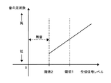
従来の、断続音方式の受信信号レベルと断続音周期の関係を図2に示す。断続音方式では、光軸を調整することで受信信号レベルが徐々に高くなり閾値2に達するまで鳴動装置は鳴動させず、閾値2から断続音を鳴動させ、受信信号レベルが高くなるとともに周期や鳴動時間を徐々に短くする。閾値1に達した後に連続音に切り替えることで、検知装置が十分な性能を発揮できる受信信号レベルに達したことがわかるものがあった。しかし、断続音方式では、連続音に切り替わった後は、受信信号レベルが上がっても同じ音が鳴り続けるため、光軸の精度を高めるためにはテスター等の表示の読み取りを行う必要があり、音では受信信号レベルがわからなくなる。 FIG. 2 shows the relationship between the received signal level of the conventional intermittent sound system and the intermittent sound period. In the intermittent sound system, the received signal level is gradually increased by adjusting the optical axis, and the ringing device is not sounded until the threshold value 2 is reached. Reduce the ring time gradually. By switching to continuous sound after reaching the threshold value 1, it has been found that the reception signal level at which the detection device can exhibit sufficient performance has been reached. However, in the intermittent sound method, after switching to continuous sound, the same sound continues to sound even if the received signal level rises, so it is necessary to read the display of a tester etc. in order to increase the accuracy of the optical axis, With sound, the received signal level is unknown.
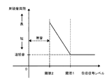
従来の、音の周波数方式の受信信号レベルと音の周波数方式の関係を図3に示す。音の周波数方式では、受信信号レベルが閾値2に達するまでは鳴動装置は鳴動させず、閾値2に達すると最も音の周波数の低い音を鳴動させ、閾値1に達した後も受信信号レベルの変化に応じて音の周波数を変化させる。この方式では最も音が高くなる方向に光軸調整することで、受信信号レベルが最大となる状態に調整することができる。しかし、音の周波数方式では閾値1に達したか否か判断することができないため、必要以上に受信信号レベルを高めることとなり調整に時間がかかる場合があったり、視線を閾値1に達したか否かを表示する表示灯や、テスターに移すことで受信信号レベルを閾値1に達したことを確認したりすることとなる。 FIG. 3 shows the relationship between the received signal level of the conventional sound frequency method and the sound frequency method. In the sound frequency method, the ringing device does not ring until the received signal level reaches the threshold value 2, but when the threshold value 2 is reached, the sound having the lowest sound frequency is sounded. The frequency of the sound is changed according to the change. In this method, the received signal level can be adjusted to the maximum by adjusting the optical axis in the direction where the sound is highest. However, since it is impossible to determine whether or not the threshold value 1 has been reached in the sound frequency method, the received signal level is increased more than necessary, and adjustment may take time, or whether the line of sight has reached the threshold value 1 It is confirmed that the received signal level has reached the threshold value 1 by moving to an indicator lamp for indicating whether or not, or to a tester.
コストの兼ね合いから前記連続音や前記断続音を鳴動させる鳴動装置として、圧電ブザーが用いられる。圧電ブザーは鳴動させる周波数によっては音圧が変わるため、鳴動させる周波数を可聴域の中でも、より狭い帯域(圧電ブザーが十分な音圧を鳴動させられる帯域)に限定する必要がある。例えば、音の周波数方式の場合、受信信号レベルが変化する範囲を一定として、周波数帯域を割り当てる範囲を狭くすると音の周波数を聴き取ることで受信信号レベルを判断することが困難となる。 A piezoelectric buzzer is used as a sounding device for sounding the continuous sound and the intermittent sound for cost reasons. Since the sound pressure of the piezoelectric buzzer varies depending on the frequency of sound, it is necessary to limit the frequency of sound to a narrower band (band where the piezoelectric buzzer can sound a sufficient sound pressure) within the audible range. For example, in the case of the sound frequency method, if the range in which the received signal level changes is constant and the range to which the frequency band is assigned is narrowed, it is difficult to determine the received signal level by listening to the sound frequency.
また、高齢者などは可聴周波数帯域が狭いため、圧電ブザーを鳴動させる周波数帯域を狭くしなければ、周波数の変化により音を聴き取ることができなくなることがある。 In addition, elderly people and the like have a narrow audible frequency band. Therefore, unless the frequency band in which the piezoelectric buzzer is sounded is narrowed, the sound may not be heard due to a change in frequency.
これらのことから、狭い音の周波数の範囲を用いて、照準器を使用したり光軸調整装置を目視したりしながら、容易に受信信号レベルの調整を完了できる方法が必要とされる。 Therefore, there is a need for a method that can easily complete the adjustment of the received signal level using a sighting device or visually observing the optical axis adjusting device using a narrow sound frequency range.
受信信号レベルが閾値2に達するまで鳴動装置は鳴動させず、閾値2から断続音方式により、断続音を鳴動させ、受信信号レベルに応じて断続音の周期や鳴動時間を変える。受信信号レベルが閾値1を超えるまで断続音方式で鳴動装置を鳴動させ、閾値1を超えた後は音の周波数方式により、連続音を鳴動させ、受信信号レベルに応じて連続音の音の周波数を変えて、鳴動装置を鳴動させる。 The ringing device does not ring until the received signal level reaches the threshold value 2, and the intermittent sound is generated from the threshold value 2 by the intermittent sound method, and the period and time of the intermittent sound are changed according to the received signal level. The ringing device is sounded by the intermittent sound method until the received signal level exceeds the threshold value 1, and after the threshold value 1, the continuous sound is sounded by the sound frequency method, and the frequency of the continuous sound according to the received signal level. To change the sound of the sounding device.
また、受信信号レベルが閾値1で切り替える際の断続音と、連続音の音の周波数を同一とすることが好ましい。 Moreover, it is preferable that the frequency of the intermittent sound and the continuous sound when the received signal level is switched at the threshold value 1 be the same.
また、断続音の一度の鳴動中に音の周波数又は音色を変化させることが好ましい。 In addition, it is preferable to change the frequency or tone color of the sound during a single ringing tone.
本発明は、従来と同じ受信信号レベルの範囲(例えば、電圧で示すと1から5ボルトなど)の受信信号レベルを音で知らせるときに音の周波数方式を使用する受信信号レベルの範囲(例えば、電圧で示すと3ボルトから5ボルトなど)は狭くなり、従来と同じ受信信号レベル変化量あたりの音の周波数変化量とした場合に必要となる音の周波数帯域が狭くなるため、可聴周波数帯域の狭い人の可聴周波数帯域外またはその近くの周波数の音を使用する必要がなくなる。このため、高齢者のように可聴周波数帯域の狭い人であっても、調整が容易となる。 The present invention provides a range of received signal levels that use a sound frequency system (for example, for example) when the received signal level is in the same range as the conventional received signal level (for example, 1 to 5 volts in terms of voltage). (3 to 5 volts in terms of voltage) is narrowed, and the sound frequency band required when the frequency change amount of the sound per received signal level change amount is the same as in the conventional case is narrowed. Eliminates the need to use sounds with frequencies outside or near the audible frequency band of narrow people. For this reason, even a person with a narrow audible frequency band such as an elderly person can easily adjust.
また、圧電ブザーが十分な音圧を鳴動させられる音の周波数帯域に限って使用することができるようになるため、音の周波数方式部分で使用する音の周波数帯域の全域で十分な音圧により鳴動することができるようになり、一般的な可聴周波数帯域の人にも聴き取りやすくすることができる。 In addition, since the piezoelectric buzzer can be used only in the sound frequency band where sufficient sound pressure can be generated, sufficient sound pressure can be obtained over the entire frequency band of the sound used in the sound frequency system part. As a result, it is possible to make a sound, and it is easy for a person in a general audible frequency band to listen.
受信信号レベルが閾値2から閾値1に達するまでは断続音方式を使用することにより音の周波数を変化させず、断続音の鳴動と鳴動の間隔や長さを変化させることで、閾値1に達した後の音の周波数方式部分で鳴動に利用する音の周波数帯域を狭くしても、従来の音の周波数方式と同等の受信信号レベル変化量あたりの周波数変化量を確保することができ、光軸調整の難易度も同等とすることができる。 Until the received signal level reaches the threshold value 1 from the threshold value 2, the threshold frequency 1 is reached by changing the interval and the length of the ringing sound without changing the sound frequency by using the intermittent sound method. Even if the frequency band of the sound used for ringing is narrowed in the frequency method part of the sound after the sound, the amount of frequency change per received signal level change amount equivalent to the conventional sound frequency method can be secured, and the light The degree of difficulty of axis adjustment can be made equal.
従来の断続音方式では閾値1に達した後は、テスター等を確認しながら調整する必要があったが、本発明によりテスター等の受信信号レベルを視覚的に表示するものを使用する必要が無いため、照準器や光軸調整装置に視線を向けて光軸調整を行うことができるようになり、光軸調整装置の操作の過誤を減らすことができ、過誤があった場合でも光軸の再調整が容易となる。 In the conventional intermittent sound method, after reaching the threshold value 1, it is necessary to make adjustment while confirming the tester, but according to the present invention, it is not necessary to use a device that visually displays the received signal level. Therefore, the optical axis can be adjusted by directing the line of sight to the sighting device or the optical axis adjustment device, so that errors in the operation of the optical axis adjustment device can be reduced. Adjustment is easy.
以下、本発明の実施の形態について説明するが、以下の説明により本発明が限定されるものではない。以下においては照準器と鳴動装置が対向型検知装置と一体となっているものを例として説明するが、警戒時には取り外し、光軸調整時にのみ取り付けるものであってもよい。また、送信機に鳴動装置、送信機と受信機のそれぞれに通信機能を備え、受信機と送信機の間で通信を行い、受信信号レベルを送信機に送ることで、送信機に備えられた鳴動装置により受信信号レベルに応じた鳴動をさせてもよい。 Hereinafter, although an embodiment of the present invention is described, the present invention is not limited by the following description. In the following, an example in which the sighting device and the ringing device are integrated with the opposed detection device will be described as an example, but it may be removed at the time of warning and attached only at the time of optical axis adjustment. Also, the transmitter is equipped with a ringing device, each of the transmitter and the receiver has a communication function, communicates between the receiver and the transmitter, and sends the received signal level to the transmitter. You may make it ring according to a received signal level with a ringing device.
以下の実施例では送信機と受信機が分かれたものを説明するが、送信機と受信機が一体となったもの(送受信機)についても発明の範囲に含まれる。これは、送受信機と反射装置(電磁波を受信した方向に反射する再帰反射板など)とを警戒区間を隔てて対向し、光軸を合せて設置する検知装置である。送信機から発射される電磁波が遮断され、送受信機の受信部に電磁波が到達しないことや、反射装置と送受信機の間を遮断や、到達する電磁波の増加や減少、位相の変化を検出して、警報信号を出力するものである。 In the following embodiments, the transmitter and the receiver are separated from each other. However, the transmitter and the receiver integrated (transceiver) are also included in the scope of the invention. This is a detection device in which a transmitter / receiver and a reflection device (such as a retroreflector that reflects electromagnetic waves in the direction in which an electromagnetic wave is received) are opposed to each other with a warning section and the optical axes are aligned. The electromagnetic wave emitted from the transmitter is blocked, the electromagnetic wave does not reach the receiver of the transmitter / receiver, the reflection device and the transmitter / receiver are blocked, the increase or decrease of the reaching electromagnetic wave, and the phase change are detected. The alarm signal is output.
本発明は、図1のような検知装置を構成する。送信機10の送信部12から電磁波11が発射され、受信機20の受信部25にて受信され、受信部25にて信号処理を行い受信信号レベル22に変換される。受信信号レベル22は受信信号レベル処理・判断部26に入力され、受信信号レベル22が閾値2に満たなければ警報出力部27に検知信号23を入力される。検知装置が光軸調整状態であれば鳴動装置28に鳴動信号24が入力される。警報出力部27に検知信号23が入力されると、警報出力部27は図示されない警報受信機に警報信号21を入力する。警報受信機は警備センターや建物の管理人室などに設置され、そこに常駐する人が監視を行う。
The present invention constitutes a detection device as shown in FIG. The electromagnetic wave 11 is emitted from the
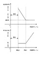
検知装置のカバーを開けると検知装置の動作状態を切り替えるスイッチが働き、警戒状態から光軸調整状態となる。検知装置が警戒状態の時、又は光軸調整状態であっても音のON/OFFスイッチがOFFとなっていた場合には鳴動信号24は出力されない。検知装置が光軸調整状態で音のON/OFFスイッチがONとなっており、かつ、受信信号レベル22が閾値2以上の時に、鳴動信号24が出力されるが、鳴動信号24は受信信号レベル22によって変化する。このときの鳴動の断続音の周期と、音の周波数、受信信号レベル22の関係を図4に示す。
When the cover of the detection device is opened, a switch for switching the operation state of the detection device is activated, and the optical axis adjustment state is changed from the alert state. The ringing
光軸調整において、未調整状態では受信信号レベル22は閾値2よりも小さくなり無音となるため、送信機と受信機にそれぞれ設けられた照準器13と照準器29を用いて、電磁波の発射方向及び受信方向を光軸調整装置14及び光軸調整装置2Aを操作することで光軸を調整する。それぞれの光軸調整装置はツマミやダイヤルであれば指で、ネジ式であればドライバーを用いて、操作する構造となっている。
In the optical axis adjustment, in the unadjusted state, the received
粗調整を行い、受信信号レベル22が閾値2に達すると、受信信号レベル処理・判断部26は鳴動信号24として断続音信号を入力し、鳴動装置28は断続音を鳴動する。受信信号レベル22が大きくなるにつれて、受信信号レベル処理・判断部26は断続音の鳴動時間と鳴動の停止時間を短くなるよう鳴動信号24を鳴動装置28に入力し、鳴動装置28は前述の鳴動信号24に従って断続音を鳴動する。これにより、調整者は受信信号レベル22を聴き分けることができるため、音を聴きながら照準器を使用しつつ、又は光軸調整装置を目視しつつ光軸を調整する。
When the rough adjustment is performed and the
さらに微調整を行い、受信信号レベル22が閾値1に達すると、受信信号レベル処理・判断部26は鳴動信号24を断続音から連続音に切り替えて鳴動装置に入力する。連続音が鳴動したということは、受信信号レベル22が閾値1に達し、検知装置がノイズと信号を弁別し、十分に性能を発揮できることを意味するため調整を完了してもよい。
When fine adjustment is further performed and the
音の周波数方式では音の周波数と受信信号レベルを対応させているため、受信信号レベル22が閾値1で断続音方式と音の周波数方式を切り替える際の断続音及び、連続音の音の周波数が離れていると、受信信号レベル22が大きく変わった場合と同じように鳴動することがある。そうすると調整者は光軸の調整に過誤があったかのように感じる場合がある。よって、図4に示すように閾値1前後の断続音及び、連続音の音の周波数は一致するように動作させることで、このような誤解を避けることができる。
Since the sound frequency method associates the sound frequency with the received signal level, the frequency of the intermittent sound and the sound of the continuous sound when the received
受信信号レベル22が閾値1に達した後も、受信信号レベル22が大きくなるにつれて連続音の音の周波数は高くなる。この音の周波数の変化を聴き取ることで受信信号レベル22を確認できるため、照準器を使用しつつ、又は光軸調整装置を目視しつつ光軸を調整する。
Even after the
このとき、音の周波数に対応して音圧を変化させることで、受信信号レベル22の調整状態はより明確となるため、音の周波数が高くなるにつれて音圧も高くなるように鳴動させる。
At this time, since the adjustment state of the
光軸を最も音の周波数又は音圧が高くなるところに調整することで、受信信号レベル22を検知器の設置環境における最大値に調整することができる。ただし、同じ機器を用いても受信信号レベル22の最大値は設置環境や送信機と受信機の距離などによって異なる。
The received
尚、上記実施例では、断続音の鳴動時の音の周波数や音色を変化させていないが、音の周波数をスイープ音などに変化させてもよい。スイープ音とは一度の鳴動中に音の周波数や音色が変化する音の事である。スイープ音のスイープ周波数範囲にブザーの特性上、音圧が高くなる音の周波数を含めることで通常の可聴周波数帯域を持つ人が聴き取りやすく、さらに高齢者等の可聴周波数帯域が狭い人でも聴き取りやすい音の周波数を含めることで、より多くの人にとって聴き取りやすくなる。 In the above embodiment, the frequency and tone color of the sound when the intermittent sound is sounded are not changed, but the frequency of the sound may be changed to a sweep sound or the like. A sweep sound is a sound whose frequency and tone change during a single ring. By including the frequency of the sound whose sound pressure increases due to the buzzer characteristics in the sweep frequency range of the sweep sound, it is easy for people with normal audible frequency bands to hear, and even those with narrow audible frequency bands such as elderly people can listen Inclusion of easy-to-take sound frequencies makes it easier for more people to listen.
また、鳴動させる音の信号は正弦波、矩形波やそれらの複合による様々なものを用いることができる。特に矩形波においては、周期を一定として、デューティ比を変えることで音色を変化させることができる。 As the sound signal to be sounded, various signals such as a sine wave, a rectangular wave, or a combination thereof can be used. In particular, in the case of a rectangular wave, the timbre can be changed by changing the duty ratio with a constant period.
上記実施例では、図4において、断続音の周期及び音の周波数は、受信信号レベルに応じて線形的に変化させたが、非線形的に(例えば対数的など)周期や音の周波数を変化させてもよい。 In the above embodiment, in FIG. 4, the period of intermittent sound and the frequency of sound are linearly changed according to the received signal level, but the period and sound frequency are changed nonlinearly (for example, logarithmically). May be.
以上、本発明の実施形態を説明したが、上述の実施形態は例として提示したものであり、発明の範囲は、これに限定するものではなく、その他の様々な形態で実施されることが可能であり、特許請求の範囲に記載された発明の範囲とその均等の範囲に含まれるものである。 Although the embodiment of the present invention has been described above, the above-described embodiment is presented as an example, and the scope of the invention is not limited to this, and can be implemented in various other forms. It is included in the scope of the invention described in the scope of claims and its equivalent scope.
10 送信機
11 電磁波
12 送信部
13 照準器
14 光軸調整装置
20 受信機
21 警報信号
22 受信信号レベル
23 検知信号
24 鳴動信号
25 受信部
26 受信信号レベル処理・判断部
27 警報出力部
28 鳴動装置
29 照準器
2A 光軸調整装置
DESCRIPTION OF
Claims (7)
前記送信機または受信機には、前記送信部より発射された電磁波を受信した受信信号レベルに応じた鳴動を行う鳴動装置を備え、
前記鳴動装置は断続音又は連続音の何れか一方を鳴動し、
前記連続音は受信信号レベルにより、音の周波数が変化し、
前記断続音は受信信号レベルにより、鳴動と鳴動の間隔または鳴動の長さまたはその両方が変化し、
前記受信信号レベルの予め設定された閾値1において前記断続音と前記連続音を切り替えることを特徴とする検知装置。 In a detection apparatus constituted by a transmitter having a transmitter for transmitting electromagnetic waves and a receiver having a receiver for receiving electromagnetic waves emitted from the transmitter,
The transmitter or receiver includes a ringing device that performs ringing according to the received signal level received from the electromagnetic wave emitted from the transmitter,
The sounding device sounds either an intermittent sound or a continuous sound,
The continuous sound changes the frequency of the sound according to the received signal level,
Depending on the received signal level, the intermittent sound changes in ringing interval and / or length of ringing,
A detection apparatus, wherein the intermittent sound and the continuous sound are switched at a preset threshold value 1 of the reception signal level.
Priority Applications (1)
| Application Number | Priority Date | Filing Date | Title |
|---|---|---|---|
| JP2017128320A JP6630889B2 (en) | 2017-06-30 | 2017-06-30 | Detection device |
Applications Claiming Priority (1)
| Application Number | Priority Date | Filing Date | Title |
|---|---|---|---|
| JP2017128320A JP6630889B2 (en) | 2017-06-30 | 2017-06-30 | Detection device |
Publications (3)
| Publication Number | Publication Date |
|---|---|
| JP2019012007A true JP2019012007A (en) | 2019-01-24 |
| JP2019012007A5 JP2019012007A5 (en) | 2019-04-18 |
| JP6630889B2 JP6630889B2 (en) | 2020-01-15 |
Family
ID=65227912
Family Applications (1)
| Application Number | Title | Priority Date | Filing Date |
|---|---|---|---|
| JP2017128320A Active JP6630889B2 (en) | 2017-06-30 | 2017-06-30 | Detection device |
Country Status (1)
| Country | Link |
|---|---|
| JP (1) | JP6630889B2 (en) |
Citations (8)
| Publication number | Priority date | Publication date | Assignee | Title |
|---|---|---|---|---|
| JPS5858411A (en) * | 1981-10-04 | 1983-04-07 | Fujio Nakamae | Distance displaying method for obstruction detector utilizing ultrasonic wave |
| JPH0415521A (en) * | 1990-05-09 | 1992-01-20 | Hitachi Ltd | Adjusting device for measuring apparatus |
| JPH09210851A (en) * | 1996-01-31 | 1997-08-15 | Otec Denshi Kk | Adjusting device for optical axis of monitoring apparatus |
| JPH11272963A (en) * | 1998-03-25 | 1999-10-08 | Optex Co Ltd | Sensor for detecting human body |
| US20040071438A1 (en) * | 2002-10-15 | 2004-04-15 | Harres Daniel N. | Method for audibly measuring optical efficiency in an installed fiber optic link |
| JP2005140717A (en) * | 2003-11-10 | 2005-06-02 | Icom Inc | Display device |
| JP2009166752A (en) * | 2008-01-18 | 2009-07-30 | Seiko Epson Corp | Pressure detection device and information display system |
| US20120023516A1 (en) * | 2010-07-21 | 2012-01-26 | Robert Wolinsky | System and method for verifying home television audience viewership via a set-top box |
-
2017
- 2017-06-30 JP JP2017128320A patent/JP6630889B2/en active Active
Patent Citations (8)
| Publication number | Priority date | Publication date | Assignee | Title |
|---|---|---|---|---|
| JPS5858411A (en) * | 1981-10-04 | 1983-04-07 | Fujio Nakamae | Distance displaying method for obstruction detector utilizing ultrasonic wave |
| JPH0415521A (en) * | 1990-05-09 | 1992-01-20 | Hitachi Ltd | Adjusting device for measuring apparatus |
| JPH09210851A (en) * | 1996-01-31 | 1997-08-15 | Otec Denshi Kk | Adjusting device for optical axis of monitoring apparatus |
| JPH11272963A (en) * | 1998-03-25 | 1999-10-08 | Optex Co Ltd | Sensor for detecting human body |
| US20040071438A1 (en) * | 2002-10-15 | 2004-04-15 | Harres Daniel N. | Method for audibly measuring optical efficiency in an installed fiber optic link |
| JP2005140717A (en) * | 2003-11-10 | 2005-06-02 | Icom Inc | Display device |
| JP2009166752A (en) * | 2008-01-18 | 2009-07-30 | Seiko Epson Corp | Pressure detection device and information display system |
| US20120023516A1 (en) * | 2010-07-21 | 2012-01-26 | Robert Wolinsky | System and method for verifying home television audience viewership via a set-top box |
Also Published As
| Publication number | Publication date |
|---|---|
| JP6630889B2 (en) | 2020-01-15 |
Similar Documents
| Publication | Publication Date | Title |
|---|---|---|
| AU652892B2 (en) | Wireless personal communicator and method of operating a portable wireless communication device | |
| US9905102B2 (en) | Open scattered light smoke detector and testing device for an open scattered light smoke detector of this type | |
| US9390605B2 (en) | Auxiliary device for a hazard alarm constructed as a point type detector for function monitoring of the hazard alarm, and an arrangement and method of monitoring using a device of this kind | |
| US5309144A (en) | Proximity sensing security system | |
| US8199608B2 (en) | System and method for adjusting sensitivity of an acoustic sensor | |
| US7957224B2 (en) | Human echolocation system | |
| US10885764B2 (en) | Method and apparatus for detecting a hazard detector signal in the presence of interference | |
| US8258949B1 (en) | Intruder detection alarm and deterrent device | |
| US10210726B2 (en) | Event detection system and method of use | |
| EP2037423A2 (en) | Apparatus and Method for Calibrating an Acoustic Detection System | |
| JP2019012007A (en) | Detector | |
| US9349269B2 (en) | Glass breakage detection system and method of configuration thereof | |
| US7902508B2 (en) | Selectable field motion detector | |
| JP2003091783A (en) | Sensor device for crime prevention | |
| KR200385668Y1 (en) | Duplex infrared sensor | |
| KR200409284Y1 (en) | Secure Monitor for Car | |
| KR20170103397A (en) | Lightning detection system | |
| JPH042896B2 (en) | ||
| JP6951242B2 (en) | Alarm device and alarm system | |
| KR200270569Y1 (en) | raser countmeasure equipment system | |
| JPH09512902A (en) | Siren detector | |
| US1831465A (en) | Radio compass system | |
| PT1347308E (en) | On board traffic monitoring device | |
| JP2019012007A5 (en) | ||
| JPH0549069A (en) | Wireless receiver for controlling lighting fixture |
Legal Events
| Date | Code | Title | Description |
|---|---|---|---|
| A521 | Request for written amendment filed |
Free format text: JAPANESE INTERMEDIATE CODE: A523 Effective date: 20190308 |
|
| A621 | Written request for application examination |
Free format text: JAPANESE INTERMEDIATE CODE: A621 Effective date: 20190308 |
|
| A871 | Explanation of circumstances concerning accelerated examination |
Free format text: JAPANESE INTERMEDIATE CODE: A871 Effective date: 20190308 |
|
| A975 | Report on accelerated examination |
Free format text: JAPANESE INTERMEDIATE CODE: A971005 Effective date: 20190521 |
|
| A131 | Notification of reasons for refusal |
Free format text: JAPANESE INTERMEDIATE CODE: A131 Effective date: 20190604 |
|
| A521 | Request for written amendment filed |
Free format text: JAPANESE INTERMEDIATE CODE: A523 Effective date: 20190724 |
|
| TRDD | Decision of grant or rejection written | ||
| A01 | Written decision to grant a patent or to grant a registration (utility model) |
Free format text: JAPANESE INTERMEDIATE CODE: A01 Effective date: 20191001 |
|
| A61 | First payment of annual fees (during grant procedure) |
Free format text: JAPANESE INTERMEDIATE CODE: A61 Effective date: 20191011 |
|
| R150 | Certificate of patent or registration of utility model |
Ref document number: 6630889 Country of ref document: JP Free format text: JAPANESE INTERMEDIATE CODE: R150 |
|
| R250 | Receipt of annual fees |
Free format text: JAPANESE INTERMEDIATE CODE: R250 |
|
| R250 | Receipt of annual fees |
Free format text: JAPANESE INTERMEDIATE CODE: R250 |