JP2019011643A - Base frame and assembling method of exterior wall panel - Google Patents
Base frame and assembling method of exterior wall panel Download PDFInfo
- Publication number
- JP2019011643A JP2019011643A JP2017129838A JP2017129838A JP2019011643A JP 2019011643 A JP2019011643 A JP 2019011643A JP 2017129838 A JP2017129838 A JP 2017129838A JP 2017129838 A JP2017129838 A JP 2017129838A JP 2019011643 A JP2019011643 A JP 2019011643A
- Authority
- JP
- Japan
- Prior art keywords
- wall
- wall surface
- wall panel
- surface material
- groundwork
- Prior art date
- Legal status (The legal status is an assumption and is not a legal conclusion. Google has not performed a legal analysis and makes no representation as to the accuracy of the status listed.)
- Granted
Links
- 238000000034 method Methods 0.000 title claims abstract description 11
- 239000000463 material Substances 0.000 claims abstract description 162
- 238000004519 manufacturing process Methods 0.000 claims description 12
- 238000003825 pressing Methods 0.000 abstract description 3
- 229910000831 Steel Inorganic materials 0.000 description 20
- 239000010959 steel Substances 0.000 description 20
- 238000003780 insertion Methods 0.000 description 4
- 230000037431 insertion Effects 0.000 description 4
- 239000011810 insulating material Substances 0.000 description 2
- 125000006850 spacer group Chemical group 0.000 description 2
- 230000000694 effects Effects 0.000 description 1
- 230000013011 mating Effects 0.000 description 1
- 239000002184 metal Substances 0.000 description 1
- 238000012986 modification Methods 0.000 description 1
- 230000004048 modification Effects 0.000 description 1
- 238000002360 preparation method Methods 0.000 description 1
Images


Abstract
Description
この発明は、上下に配置した外壁面材を下地材で連結した外壁パネルを建物躯体の外壁取付箇所とは異なる場所で組み立てるのに用いられる地組架台、および上記地組架台を用いた外壁パネルの作製方法に関する。 The present invention relates to a ground frame used for assembling an outer wall panel in which upper and lower outer wall materials are connected by a base material at a place different from an outer wall mounting position of a building frame, and an outer wall panel using the ground frame It relates to a manufacturing method.
特許文献1には、建物躯体への取付状態で上下方向に並ぶ複数枚の外壁パネルを、上記建物躯体への取付け用の下地となり、上記外壁パネルの横幅方向に並んでそれぞれ上下方向に延びる複数本の胴縁に、上記建物躯体の外壁パネル取付け箇所とは別の場所で組み付けて下地一体型の外壁パネルユニットとする作業に用いる地組架台であって、自立する地組架台本体と、この地組架台本体にそれぞれ取付けられ、上記外壁パネルユニットのユニット化前の上記複数本の各胴縁を、ユニット化後の配置関係でかつ立ち姿勢として、その下端および上部で位置決め状態に保持する複数の下端固定治具および上側固定治具と、を備える、外壁パネルの地組架台が開示されている。 In Patent Document 1, a plurality of outer wall panels arranged in the vertical direction in a state of being attached to the building frame serve as a base for mounting to the building frame, and extend in the vertical direction along the lateral width direction of the outer wall panel. A ground frame used for the work of assembling a base wall-integrated outer wall panel unit by assembling to the body edge of the book at a location different from the location of the outer wall panel of the building frame, A plurality of each of the plurality of body edges, which are respectively attached to the groundwork frame main body, and held in the positioning state at the lower end and the upper portion thereof in the arrangement relation and the standing posture after the unitization as the united state of the outer wall panel unit. An outer wall panel base frame comprising a lower end fixing jig and an upper side fixing jig is disclosed.
上記特許文献1は、外壁パネルの下地材(縦胴縁)の位置決め技術について開示するに過ぎない。ここで、上記外壁パネルの外壁面材については、固定済の下側の外壁面材の上側に外壁面材を配置するときに、この上側の外壁面材の上端を押さえて下方への力を付与し、下側の外壁面材と上側の外壁面材との間の目地の幅(上下間隔)が所定寸法となったときに、上側の外壁面材を下地材に固定することが考えられる。 The above-mentioned patent document 1 only discloses a positioning technique for the base material (vertical trunk edge) of the outer wall panel. Here, with respect to the outer wall surface material of the outer wall panel, when the outer wall surface material is disposed on the upper side of the fixed lower outer wall surface material, the upper wall surface material on the upper side is pressed to exert downward force. It is conceivable that the upper outer wall surface material is fixed to the base material when the joint width (vertical interval) between the lower outer wall surface material and the upper outer wall surface material reaches a predetermined dimension. .
この場合、上側の外壁面材の上端を押さえるときの作業目線と、上記目地の幅を計測するときの作業目線との間には、外壁面材の縦寸法程度の距離の開きが生じることになる。このため、一人の作業者で上記目地の幅の計測をしつつ外壁面材の位置調整を行うことは容易ではなく、また、作業者を複数人で行うのでは、コストが上昇することになる。 In this case, there is an opening of a distance of about the vertical dimension of the outer wall surface material between the work eye line when pressing the upper end of the upper outer wall material and the work eye line when measuring the joint width. Become. For this reason, it is not easy to adjust the position of the outer wall surface material while measuring the joint width by one worker, and the cost increases if a plurality of workers are used. .
この発明は、上記の事情に鑑み、外壁パネルの外壁面材の位置決めが的確に行える地組架台および外壁パネルの作製方法を提供することを課題とする。 This invention makes it a subject to provide the manufacturing method of the groundwork stand which can position the outer wall surface material of an outer wall panel accurately, and an outer wall panel in view of said situation.
この発明の地組架台は、上記の課題を解決するために、複数の外壁面材を上下に並べて下地材で連結した外壁パネルを、当該外壁パネルが取り付けられる建物躯体の取付箇所とは異なる場所で組み立てるための地組架台であって、上記複数の外壁面材の上下間隔揃えと側面揃えの少なくとも一方を行うための位置基準部を備えたことを特徴とする。 In order to solve the above-mentioned problem, the ground frame of the present invention is a place different from the mounting position of the building frame to which the outer wall panel is attached, by arranging the outer wall panel in which a plurality of outer wall materials are arranged vertically and connected by a base material. And a position reference part for performing at least one of vertical interval alignment and side surface alignment of the plurality of outer wall surface materials.
上記の構成によれば、上記複数の外壁面材の上下間隔揃えと側面揃えの少なくとも一方を行うための位置基準部を地組架台に備えたので、外壁パネルの外壁面材の位置決めが的確に行えることになる。 According to the above configuration, since the ground frame has the position reference portion for performing at least one of the vertical interval alignment and the side surface alignment of the plurality of outer wall materials, the positioning of the outer wall materials of the outer wall panel can be accurately performed. It will be possible.
上記位置基準部として、上記外壁面材を上記下地材に固定する位置での当該外壁面材の上端が位置する箇所に、マークが付されていてもよい。これによれば、作業者は、上記外壁面材の上端を治具等で押さえ、当該上端を上記マークの位置に合わせることで、下側の外壁面材と上側の外壁面材との間の目地の幅(上下間隔)を規定値に合わせることができる。したがって、上下の外壁面材の目地の幅を直接的に計測する必要がなくなり、例えば、一人の作業者によって上記目地の幅を規定値に合わせつつ外壁面材を固定していくことが容易になる。 As the position reference portion, a mark may be attached at a position where the upper end of the outer wall surface material is positioned at a position where the outer wall surface material is fixed to the base material. According to this, the operator presses the upper end of the outer wall surface material with a jig or the like, and aligns the upper end with the position of the mark so that the space between the lower outer wall surface material and the upper outer wall surface material is reduced. The joint width (vertical spacing) can be adjusted to a specified value. Therefore, there is no need to directly measure the joint width of the upper and lower outer wall materials, and for example, it is easy to fix the outer wall material while adjusting the joint width to a specified value by one worker. Become.
上記マークは、上記外壁面材の後面側に位置する支柱部の前側の面に付されていてもよい。 The said mark may be attached | subjected to the surface of the front side of the support | pillar part located in the rear surface side of the said outer wall surface material.
上記位置基準部として、上記外壁面材の側面に存在する突出部と干渉しないように当該突出部よりも前側の側面部分に接触する接触部を有していてもよい。これによれば、目につく上記外壁面材の前側を基準にして、上記位置基準部である上記接触部による上記外壁面材の側面揃えが行える。 The position reference portion may include a contact portion that contacts a side surface portion on the front side of the protrusion so as not to interfere with the protrusion existing on the side surface of the outer wall surface material. According to this, the side surface alignment of the outer wall surface material by the contact portion which is the position reference portion can be performed with reference to the front side of the noticeable outer wall surface material.
上記接触部は、当該地組架台を構成する支柱部または梁部に設けられていてもよい。 The said contact part may be provided in the support | pillar part or beam part which comprises the said groundwork stand.
また、この発明の外壁パネルの作製方法は、複数の外壁面材を上下に並べて下地材で連結した外壁パネルを、当該外壁パネルが取り付けられる建物躯体の取付箇所とは異なる場所で組み立てるための地組架台を用いて外壁パネルを作製する方法であって、上記地組架台には、上記外壁面材を上記下地材に固定する位置での当該外壁面材の上端が位置する箇所においてマークが付されており、上記外壁面材の上端を下方に押さえることで当該外壁面材の上端を上記マークの位置に合わせて上記下地材に固定することを特徴とする。 Further, according to the manufacturing method of the outer wall panel of the present invention, an outer wall panel in which a plurality of outer wall materials are arranged in a vertical direction and connected by a base material is assembled on a ground for assembling at a place different from a mounting position of a building frame to which the outer wall panel is attached. A method for producing an outer wall panel using an assembling stand, wherein the ground assembling stand is marked at a position where an upper end of the outer wall surface material is located at a position where the outer wall surface material is fixed to the base material. The upper end of the outer wall surface material is pressed downward, and the upper end of the outer wall surface material is fixed to the base material in accordance with the position of the mark.
上記の方法によれば、作業者は、上記外壁面材の上端を治具等で押さえ、当該上端を上記マークの位置に合わせることで、下側の外壁面材と上側の外壁面材との間の目地の幅を規定値に合わせることができる。したがって、上下の外壁面材の目地の幅を直接的に計測する必要がなくなり、例えば、一人の作業者によって上記目地の幅を規定値に合わせつつ外壁面材を固定していくことが容易になる。 According to the above method, the operator holds the upper end of the outer wall surface material with a jig or the like, and aligns the upper end with the position of the mark so that the lower outer wall surface material and the upper outer wall surface material are aligned. The width of the joints can be adjusted to the specified value. Therefore, there is no need to directly measure the joint width of the upper and lower outer wall materials, and for example, it is easy to fix the outer wall material while adjusting the joint width to a specified value by one worker. Become.
上記の方法において、上記外壁面材の上端が、前後に分かれた同一高さの2個の凸部からなる場合、前側の凸部を上記マークの位置に合わせるようにしてもよい。これによれば、目につく上記外壁面材の前側を基準にして、上記マークによる上記外壁面材の目地寸法合わせが行われる。 In the above method, when the upper end of the outer wall surface material is composed of two convex portions having the same height divided in the front and rear, the front convex portion may be aligned with the position of the mark. According to this, the joint size adjustment of the outer wall surface material by the mark is performed with reference to the front side of the noticeable outer wall surface material.
本発明であれば、外壁パネルの外壁面材の位置決めが的確に行えるという効果を奏する。 If it is this invention, there exists an effect that positioning of the outer wall surface material of an outer wall panel can be performed exactly.
以下、この発明の実施の形態を添付図面に基づいて説明する。
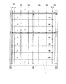
図1に示すように、外壁パネル5は、複数の横長の外壁面材51を上下に並べて下地材52で相互に連結された構造を有する。図1に示す例では、上記下地材52として、最も端位置の2本の縦胴縁52aと、中央側の例えば4本の縦胴縁52bを備えている。上記縦胴縁52aは、角形鋼管等の閉鎖断面鋼材からなっている。一方、上記縦胴縁52bは、リップ溝型鋼や溝型鋼等の開放断面鋼材からなる。なお、下地材52の全てを閉鎖断面鋼材である縦胴縁52aとすることもでき、また、下地材52の全てを開放断面鋼材である縦胴縁52bとすることもできる。
Embodiments of the present invention will be described below with reference to the accompanying drawings.
As shown in FIG. 1, the
上記外壁面材51の端面の前後幅方向の略中央には、突出部51gが形成されている。また、上記外壁面材51は、例えば、図2(A)および図2(B)に示すように、不燃断熱材51aを鋼板51b、51cで挟み込んだ金属サンドイッチパネルである。2枚の外壁面材51を上下に並べた場合、下段に位置する外壁面材51の上端面に形成された横幅方向に長い2か所の凹部51dに、上段に位置する外壁面材51の下端面に形成された横幅方向に長い2か所の凸部51eが嵌まり込むことにより、上下の外壁面材51が互いに面外方向に位置ずれしないように組み合わされる。なお、上下の外壁面材51により形成される目地の幅(高さ)Xは、例えば、10mm幅とされる。
A protruding
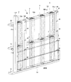
図3および図4に示すように、地組架台1を用いることによって、上記複数の外壁面材51を上下に並べて下地材52で連結した外壁パネル5を、当該外壁パネル5が取り付けられる建物躯体の外壁取付箇所とは異なる場所で組み立てることができる。なお、図4では、地組架台1を簡略化して示している。また、この図4において、「前側」は、地組架台1を構成する各部材についての前面側とされ、また、上記外壁面材51等についても、その前面側を上記「前側」に向けた状態でセットされるものとする。
As shown in FIG. 3 and FIG. 4, by using the groundwork frame 1, an
上記地組架台1は、上記外壁面材51の側面側に位置する支柱部11Aと、上記外壁面材51の後面側となる位置に配置された奥側支柱部11Bと、上記支柱部11A、11Bの下側と中側と上側とにそれぞれ掛け渡される3本の梁部12と、を備える。
The ground frame 1 includes a
例えば、上記支柱部11Aの下部側は、下側の梁部12の前面側に固定されており、上記支柱部11Aの中央側および上部側は、中側と上側の梁部12の前面側にスペーサ11aを介してそれぞれ固定されている。中側と上側の梁部12は、上記縦胴縁52a、52bの後面側に設けられる。また、上記奥側支柱部11Bの下端は、下側の梁部12の上面上に固定され、上記奥側支柱部11Bの上部は、上側の梁部12の前面側に固定されている。
For example, the lower side of the
上記梁部12は、例えば、架台支持フレームに固定される。また、例えば、最下の梁部12の前側部に面材載置部が形成されており、この面材載置部上に最下段の外壁面材51が置かれる。
The
上段に位置する上記梁部12および中段に位置する上記梁部12上には、閉鎖断面鋼材からなる上記縦胴縁52aを保持する下地材保持具2および開放断面鋼材からなる上記縦胴縁52bを保持する下地材保持具3が固定されている。なお、下段に位置する上記梁部12には、図示していないが、上記縦胴縁52a、52bが差し込まれる位置決め凸部或いは上記縦胴縁52a、52bの側面が当接される位置決め板部が設けられる。
On the
図4に示したごとく、上記縦胴縁52a、52bをセットした後、外壁面材51をセットしていく。この時に、外壁面材51に面外方向の反りがあれば、図示しない反り矯正手段によって強制することもできる。作業者は、セットした上記外壁面材51の上端部側にビス等をねじ込み、上記外壁面材51を先にセットした上記縦胴縁52a、52bに固定する。
As shown in FIG. 4, after setting the vertical trunk edges 52a and 52b, the outer
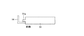
また、上下に配置される複数の外壁面材51については、図5に示すように、位置基準部としての接触部材14の突出板部を基準面とし、この基準面に外壁面材51の一端を押し当てることで、複数の外壁面材51の縁を互いに揃えるようにしている。上記接触部材14は、例えば、Lアングルをその長手方向が鉛直を向くように配置され、このLアングルにおける一方の板部が上記突出板部とされる。ここで、上記外壁面材51の上記突出部51gと干渉しないように、上記接触部材14の突出板部は、上記突出部51gよりも前側となる箇所の上記外壁面材51の側面部に接触するように設けられている。換言すれば、目につく上記外壁面材51の前側において、上記接触部材14による上記外壁面材51の側面揃えが行われる。
In addition, as shown in FIG. 5, the plurality of outer
また、上下に配置される複数の外壁面材51の横目地の幅(高さ)Xについては、図9に示すように、調整治具500によって上側の外壁面材51を下側に押さえることで、上下の外壁面材51にできる目地の幅Xを、例えば一定の10mmに調節することができる。上記目地の高さXを一定に揃えるために、上記外壁面材51の後面側に位置する支柱部11Bの前側の面に、位置基準部として複数のマークMが墨或いはテープ等によって付されている。上記マークMは、上記外壁面材51を上記下地材52に固定する各位置での当該外壁面材51の上端(凸部51e)が位置する箇所ごと(高さごと)に付されている。外壁パネル5の作製法の詳細については、後述する。
Further, as shown in FIG. 9, the width (height) X of the horizontal joints of the plurality of
また、図6に示すように、上記下地材保持具2,3によって上記縦胴縁52a、52bの前後方向の移動規制がされた状態で、外壁面材51を上記縦胴縁52a、52bに固定していく際に、上記下地材保持具2を操作することができ、また、外壁パネル5が完成された後には、上記下地材保持具2、3を操作して、上記外壁パネル5を地組架台1から取り外すことができる。
Further, as shown in FIG. 6, the
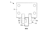
上記下地材保持具2は、例えば、図7に示すように、ベース板21を備える。このベース板21にはボルト挿通孔が形成されており、このボルト挿通孔にボルトを挿通し、上記梁部12に形成されている螺子孔にねじ込むことで、上記ベース板21が上記梁部12に固定される。
The
上記下地材保持具2は、前側に突出するように片部22(第2固定部)を備える。上記ベース板21の前側の辺(第1固定部)と、この辺に直交する上記片部22(第2固定部)の辺とにより、閉鎖断面鋼材からなる上記縦胴縁52aの後面を含む隣り合う2面に接触する固定接触部が形成される。そして、上記片部22から上記縦胴縁52aの幅相当の間隔をおいて、上記縦胴縁52aの前面を含む他の隣り合う2面に接触および離脱が行える可動接触部23が設けられている。上記下地材保持具2は、上記片部22による固定接触部と上記可動接触部23とにより、上記閉鎖断面鋼材からなる上記縦胴縁52aの外面に接触し、上記縦胴縁52aの左右移動および前後移動を規制する規制状態と、上記規制状態を解除する解除状態とを形成することができる。
The
上記可動接触部23は、第1片部23aを回動自在に支持するように上記ベース板21上に設けられた蝶番23bと、上記第1片部23aの端側で第2片部23cを回動自在に支持する蝶番23dと、上記第2片部23cの略中央側で第3片部23eを回動自在に支持する蝶番23fとを備える。上記蝶番23bおよび蝶番23dは上記ベース板21の前側の辺と平行に回動軸を有しており、上記蝶番23fは上記前側の辺と略同一面内で直交する方向に回動軸を有している。
The
上記縦胴縁52bを保持する下地材保持具3は、例えば、図8に示すように、ベース板31を備える。このベース板31にはボルト挿通孔が形成されており、このボルト挿通孔にボルトを挿通し、上記梁部12に形成されている螺子孔にねじ込むことで、上記ベース板31が上記梁部12に固定される。
The
上記下地材保持具3は、前側に突出するように固定片部32を備える。この固定片部32には、上記縦胴縁52bとしてのリップ溝形鋼におけるリップ部に係合する係合部32aが形成されている。上記リップ溝形鋼における後面側が上記ベース板31の前側の辺に当たり、上記係合部32aをリップ部に係合させることで、上記縦胴縁52bの前後移動を規制する規制状態を形成することができる。また、上記固定片部32から上記縦胴縁52bの幅相当の間隔をおいて、上記縦胴縁52bの側面に接触および離脱が行える可動接触部33が設けられている。上記可動接触部33は、上記縦胴縁52bの側面に接触する片部33aを、を上記ベース板31上に設けた蝶番33bによって、回動自在に支持している。
The
図9に、この実施形態の外壁パネルの作製方法の一例を示す。この作製方法では、上記外壁面材51を上記下地材52に固定する位置での当該外壁面材51の上端が位置する箇所においてマークMが付された上記地組架台1を用いて外壁パネルを作製する。そして、この方法においては、例えば、調整治具500を用い、既設の下側の外壁面材51から力を得て、未固定の上側の外壁面材51を下側に押さえる。すなわち、上記調整治具500の下部を既設の下側の外壁面材51の下部に係合させ、上記調整治具500の上部を未固定の上側の外壁面材51の上端に係合させ、上記上部の握り部に連結されているボールねじ部を回すことで、上側の外壁面材51を下側に押さえる。作業者は、このように、上側の外壁面材51を下方に押さえる操作を行い、当該外壁面材51の上端を上記マークMの位置に合わせた後に、上側の外壁面材51をビス等によって上記下地材52に固定する。
FIG. 9 shows an example of a method for producing the outer wall panel of this embodiment. In this manufacturing method, an outer wall panel is formed using the above-mentioned groundwork frame 1 to which the mark M is attached at a position where the upper end of the outer
上記の方法によれば、作業者は、上記外壁面材51の上端を治具等で押さえ、当該上端を上記マークMの位置に合わせることで、下側の外壁面材51と上側の外壁面材51との間の目地の幅Xを規定値に合わせることができる。したがって、上下の外壁面材51の目地Xの幅を直接的に計測する必要がなくなり、例えば、一人の作業者によって上記目地の幅Xを規定値に合わせつつ外壁面材51を固定していくことが容易になる。
According to the above method, the operator holds the upper end of the outer
ここで、上記外壁面材51の上端が前後に分かれた同一高さの2個の凸部51eからなる場合、前側の凸部51eを上記マークMの位置に合わせるようにしてもよい(図2参照)。これによれば、目につく上記外壁面材51の前側を基準にして、上記マークMによる上記外壁面材51の目地寸法合わせが行われる。なお、上記接触部材14についても、目につく上記外壁面材51の前側において、上記接触部材14による上記外壁面材51の側面揃えが行われている。
Here, in the case where the upper end of the
また、上記地組架台1は、同一の外壁パネル5の作製において繰り返し用いることができる。仕様が異なる外壁パネルを作製するときには、この仕様に合わせて上記マークMを付しなおせばよい。
Moreover, the above-mentioned groundwork frame 1 can be used repeatedly in the production of the same
以上、図面を参照してこの発明の実施形態を説明したが、この発明は、図示した実施形態のものに限定されない。図示した実施形態に対して、この発明と同一の範囲内において、あるいは均等の範囲内において、種々の修正や変形を加えることが可能である。 As mentioned above, although embodiment of this invention was described with reference to drawings, this invention is not limited to the thing of embodiment shown in figure. Various modifications and variations can be made to the illustrated embodiment within the same range or equivalent range as the present invention.
1 :地組架台
2 :下地材保持具(閉鎖断面鋼材)
3 :下地材保持具(開放断面鋼材)
5 :外壁パネル
11A :支柱部
11B :奥側支柱部
11a :スペーサ
12 :梁部
14 :接触部材(接触部)
21 :ベース板
22 :片部
23 :可動接触部
23a :第1片部
23b :蝶番
23c :第2片部
23d :蝶番
23e :第3片部
23f :蝶番
31 :ベース板
32 :固定片部
32a :係合部
33 :可動接触部
33a :片部
33b :蝶番
51 :外壁面材
51a :不燃断熱材
51b :鋼板
51c :鋼板
51d :凹部
51e :凸部
51g :突出部
52 :下地材
52a :縦胴縁(閉鎖断面)
52b :縦胴縁(開放断面)
500 :調整治具
M :マーク
X :目地幅
1: Groundwork stand 2: Base material holder (closed section steel)
3: Base material holder (open section steel)
5:
21: base plate 22: piece portion 23:
52b: Vertical trunk edge (open cross section)
500: Adjustment jig M: Mark X: Joint width
Claims (7)
上記複数の外壁面材の上下間隔揃えと側面揃えの少なくとも一方を行うための位置基準部を備えたことを特徴とする地組架台。 A ground frame for assembling an outer wall panel in which a plurality of outer wall materials are arranged vertically and connected with a base material at a location different from the mounting location of the building frame to which the outer wall panel is attached,
A groundwork frame comprising a position reference portion for performing at least one of vertical interval alignment and side surface alignment of the plurality of outer wall surfaces.
Priority Applications (1)
| Application Number | Priority Date | Filing Date | Title |
|---|---|---|---|
| JP2017129838A JP7100430B2 (en) | 2017-06-30 | 2017-06-30 | How to make an outer wall panel |
Applications Claiming Priority (1)
| Application Number | Priority Date | Filing Date | Title |
|---|---|---|---|
| JP2017129838A JP7100430B2 (en) | 2017-06-30 | 2017-06-30 | How to make an outer wall panel |
Publications (2)
| Publication Number | Publication Date |
|---|---|
| JP2019011643A true JP2019011643A (en) | 2019-01-24 |
| JP7100430B2 JP7100430B2 (en) | 2022-07-13 |
Family
ID=65227799
Family Applications (1)
| Application Number | Title | Priority Date | Filing Date |
|---|---|---|---|
| JP2017129838A Active JP7100430B2 (en) | 2017-06-30 | 2017-06-30 | How to make an outer wall panel |
Country Status (1)
| Country | Link |
|---|---|
| JP (1) | JP7100430B2 (en) |
Citations (7)
| Publication number | Priority date | Publication date | Assignee | Title |
|---|---|---|---|---|
| JPH01154967A (en) * | 1987-12-11 | 1989-06-16 | Bridgestone Corp | Method of construction of dry type concrete block |
| JPH0486855U (en) * | 1990-12-06 | 1992-07-28 | ||
| JPH0589704U (en) * | 1992-05-06 | 1993-12-07 | ミサワホーム株式会社 | Half-divided material pressing jig for panel |
| JP2004068523A (en) * | 2002-08-09 | 2004-03-04 | Kondo Kinzoku Kogyo Kk | No-scaffolding construction method for assembling building material |
| JP2012172347A (en) * | 2011-02-18 | 2012-09-10 | Nippon Steel & Sumikin Coated Sheet Corp | Joint width adjusting jig |
| JP2016094786A (en) * | 2014-11-17 | 2016-05-26 | 株式会社フジタ | Basic assembly frame of outer wall panel and construction method |
| JP2018053624A (en) * | 2016-09-30 | 2018-04-05 | 大和ハウス工業株式会社 | Field-assembled frame of exterior wall panel |
-
2017
- 2017-06-30 JP JP2017129838A patent/JP7100430B2/en active Active
Patent Citations (7)
| Publication number | Priority date | Publication date | Assignee | Title |
|---|---|---|---|---|
| JPH01154967A (en) * | 1987-12-11 | 1989-06-16 | Bridgestone Corp | Method of construction of dry type concrete block |
| JPH0486855U (en) * | 1990-12-06 | 1992-07-28 | ||
| JPH0589704U (en) * | 1992-05-06 | 1993-12-07 | ミサワホーム株式会社 | Half-divided material pressing jig for panel |
| JP2004068523A (en) * | 2002-08-09 | 2004-03-04 | Kondo Kinzoku Kogyo Kk | No-scaffolding construction method for assembling building material |
| JP2012172347A (en) * | 2011-02-18 | 2012-09-10 | Nippon Steel & Sumikin Coated Sheet Corp | Joint width adjusting jig |
| JP2016094786A (en) * | 2014-11-17 | 2016-05-26 | 株式会社フジタ | Basic assembly frame of outer wall panel and construction method |
| JP2018053624A (en) * | 2016-09-30 | 2018-04-05 | 大和ハウス工業株式会社 | Field-assembled frame of exterior wall panel |
Also Published As
| Publication number | Publication date |
|---|---|
| JP7100430B2 (en) | 2022-07-13 |
Similar Documents
| Publication | Publication Date | Title |
|---|---|---|
| KR20160038186A (en) | Shear test apparatus | |
| JP2019011643A (en) | Base frame and assembling method of exterior wall panel | |
| CN203791887U (en) | Workpiece positioning mechanism used for automobile welding tool | |
| JP6888935B2 (en) | Exterior wall panel base | |
| TWI653925B (en) | Lifting mechanism, thin support device and method for forming the same | |
| JP6965045B2 (en) | Method of manufacturing outer wall panel using base material holder, base material holder and base material | |
| CN109367212B (en) | Screen printing screen frame system capable of being positioned quickly | |
| KR20080004683U (en) | Punch press machine for Bus bar | |
| JP6970539B2 (en) | How to make the outer wall panel and opening equipment | |
| JP6403165B2 (en) | Manufacturing method and jig for structural material | |
| JP6452157B2 (en) | Framework material manufacturing method and framework material manufacturing apparatus | |
| KR200479692Y1 (en) | Align jig device for welding | |
| CN212683178U (en) | Machining tool for connecting rod cast steel piece | |
| JP6888936B2 (en) | Exterior wall panel base | |
| CN211465313U (en) | T-shaped joint welding fixture | |
| JP6770390B2 (en) | Exterior wall panel base | |
| JP7456832B2 (en) | Base assembly frame for exterior wall panels | |
| JP7005014B2 (en) | Steel manufacturing equipment | |
| CN219571302U (en) | Mounting seat mechanism of tension machine | |
| CN213135885U (en) | Clamp for resetting and assembling supporting seat | |
| CN218134404U (en) | Printing plate material optical auxiliary alignment mechanism that bends | |
| CN210464317U (en) | Spring free height screening tool | |
| CN116519449A (en) | Clamp for compression test of cementing repair part of composite material sheet | |
| KR102459865B1 (en) | Welding jig device for manufacturing side frame of assembling panel | |
| JP4163095B2 (en) | Assembly jig and blade leading edge assembly method |
Legal Events
| Date | Code | Title | Description |
|---|---|---|---|
| A621 | Written request for application examination |
Free format text: JAPANESE INTERMEDIATE CODE: A621 Effective date: 20200618 |
|
| A977 | Report on retrieval |
Free format text: JAPANESE INTERMEDIATE CODE: A971007 Effective date: 20210520 |
|
| A131 | Notification of reasons for refusal |
Free format text: JAPANESE INTERMEDIATE CODE: A131 Effective date: 20210601 |
|
| A521 | Request for written amendment filed |
Free format text: JAPANESE INTERMEDIATE CODE: A523 Effective date: 20210730 |
|
| A131 | Notification of reasons for refusal |
Free format text: JAPANESE INTERMEDIATE CODE: A131 Effective date: 20211221 |
|
| A521 | Request for written amendment filed |
Free format text: JAPANESE INTERMEDIATE CODE: A523 Effective date: 20220209 |
|
| TRDD | Decision of grant or rejection written | ||
| A01 | Written decision to grant a patent or to grant a registration (utility model) |
Free format text: JAPANESE INTERMEDIATE CODE: A01 Effective date: 20220607 |
|
| A61 | First payment of annual fees (during grant procedure) |
Free format text: JAPANESE INTERMEDIATE CODE: A61 Effective date: 20220701 |
|
| R150 | Certificate of patent or registration of utility model |
Ref document number: 7100430 Country of ref document: JP Free format text: JAPANESE INTERMEDIATE CODE: R150 |