JP2019010697A - Cut blade for slit formation and medical rubber valve formed of slit using the same - Google Patents
Cut blade for slit formation and medical rubber valve formed of slit using the same Download PDFInfo
- Publication number
- JP2019010697A JP2019010697A JP2017127823A JP2017127823A JP2019010697A JP 2019010697 A JP2019010697 A JP 2019010697A JP 2017127823 A JP2017127823 A JP 2017127823A JP 2017127823 A JP2017127823 A JP 2017127823A JP 2019010697 A JP2019010697 A JP 2019010697A
- Authority
- JP
- Japan
- Prior art keywords
- blade
- slit
- cutting blade
- rubber valve
- radius
- Prior art date
- Legal status (The legal status is an assumption and is not a legal conclusion. Google has not performed a legal analysis and makes no representation as to the accuracy of the status listed.)
- Granted
Links
Images


Abstract
Description
この発明は、医療用ゴム製弁にスリットを形成するためのカット刃及びに当該カット刃を用いてスリットが形成された医療用ゴム製弁に関する。 The present invention relates to a cutting blade for forming a slit in a medical rubber valve and a medical rubber valve in which a slit is formed using the cutting blade.
止血弁等として用いられる医療用のゴム製弁が公知である。係る医療用ゴム製弁には、弁の中央部に針やカテーテル等を刺せるように、通常、三叉のスリットが形成されている(例えば、特許文献1、2及び3を参照)。
Medical rubber valves used as hemostasis valves and the like are known. Such a medical rubber valve is generally formed with a trident slit so that a needle, a catheter, or the like can be inserted into the central portion of the valve (see, for example,
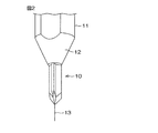
医療用ゴム製弁の製造時、弁の中央部に三叉のスリットを形成するに際しては、三叉状のカット刃が用いられる。一例として、ゴム製弁1が特許文献1に記載のような形状の場合、すなわち、図1に示すような弁体部2と、弁体部2の周縁から立ち上がった筒体部3とを含む形状の場合、カット刃10を、ゴム製弁1の筒体部3の一端に開口した穴4(穴4の半径はb)から挿入し、弁体部2の天面5から中央部を貫通させて、弁体部2にスリットを形成する。その際、受け板6にゴム製弁1を乗せ、周囲をホールドプレート7で囲む。
When forming a three-pronged slit at the center of the valve at the time of manufacturing a medical rubber valve, a trident-shaped cutting blade is used. As an example, when the
弁体部2にスリットを形成する時、ゴムはカット刃10の進入に対して外側へ逃げようとする性質があり、形成されるスリットの長さcと、カット刃10の刃径(半径)aとの関係は、0.4≦c/a≦0.6というものが一般的である。
このため、スリットの長さcを長くするためには、カット刃10の刃径(半径)aを大きくすればよいのであるが、カット刃10の刃径(半径)aを大きくすると、カット刃10が筒体部3の穴4と干渉し、穴4が損傷する虞がある。
When the slit is formed in the valve body 2, the rubber has a property of trying to escape outward with respect to the entry of the
Therefore, in order to increase the length c of the slit, the blade diameter (radius) a of the
この発明は、上記の課題を解決するためになされたものであり、ゴム製弁により長いスリットを形成することのできるスリット形成用のカット刃を提供することを主たる目的とする。
この発明は、また、耐久性に優れたスリット形成用のカット刃を提供することを他の目的とする。
The present invention has been made to solve the above-described problems, and has as its main object to provide a slit-forming cutting blade capable of forming a long slit with a rubber valve.
Another object of the present invention is to provide a slit forming blade having excellent durability.
上記目的を達成するためのこの発明は、以下の構成を有している。
第1の発明は、ゴム製の弁の天面部に三叉のスリットを形成するためのカット刃であって、前記カット刃は、軸芯に対して3等配の角度位置に設けられた3つのカット刃を含み、各カット刃は、その刃径(半径)aが、0.9mm≦a≦1.1mmで、かつ、先端部の角度が15〜25°であり、カット刃同士で形成される刃先の角度が80〜180°であることを特徴とするスリット形成用のカット刃である。
In order to achieve the above object, the present invention has the following configuration.
1st invention is a cutting blade for forming a trident slit in the top | upper surface part of a rubber-made valve, Comprising: The said cutting blade is provided in three angular positions of 3 equal intervals with respect to the axial center. Each cutting blade includes a cutting blade, and has a blade diameter (radius) a of 0.9 mm ≦ a ≦ 1.1 mm and an angle of the tip portion of 15 to 25 °, and is formed by cutting blades. The cutting blade for slit formation is characterized in that the angle of the cutting edge is 80 to 180 °.
第2の発明は、前記カット刃は、刃の材質がコバルトを6〜14%含有する超硬合金、超微粒子超硬合金または超々微粒子超硬合金のいずれかであることを特徴とするスリット形成用のカット刃である。
第3の発明は、第1または第2の発明に係るカット刃を用いてスリットが形成された医療用ゴム製弁であって、形成された三叉スリットの一辺の長さcとスリット形成に用いられた前記カット刃の刃径(半径)aとの関係が、0.6≦c/a≦0.9であることを特徴とする医療用ゴム製弁である。
According to a second aspect of the present invention, the cutting blade is formed of any one of a cemented carbide containing 6 to 14% cobalt, an ultrafine particle cemented carbide, or an ultra ultrafine particle cemented carbide. It is a cutting blade for.
The third invention is a medical rubber valve in which a slit is formed using the cutting blade according to the first or second invention, and is used for the length c of one side of the formed trident slit and the slit formation. The medical rubber valve is characterized in that a relationship with a blade diameter (radius) a of the cut blade is 0.6 ≦ c / a ≦ 0.9.
この発明によれば、ゴム製の弁に三叉のスリットを形成するに際し、相対的に長さの長い三叉のスリットを形成することができる。また、この発明によれば、カット刃が耐久性に優れ、長期間良好にスリットを形成できる。
よって、この発明のカット刃を用いてスリットが形成された医療用ゴム製弁は、性能や使用勝手の良いゴム製弁となる。
According to the present invention, when the trident slit is formed in the rubber valve, the trident slit having a relatively long length can be formed. Moreover, according to this invention, a cutting blade is excellent in durability, and can form a slit favorably for a long period of time.
Therefore, the medical rubber valve in which the slit is formed using the cutting blade of the present invention is a rubber valve having good performance and ease of use.
以下には、図面を参照して、この発明の一実施形態について説明する。
図2は、この発明の一実施形態に係る三叉状のカット刃10を示す斜視図である。カット刃10は、ボディ軸11の先端が縮径するテーパ12に加工され、テーパ12の先端から軸芯13方向に直線状に突出している。カット刃10は、ボディ軸11との一体成形品である。カット刃10は、図3(B)の正面図に示すように。軸芯13の回りに、120°の角度をあけて三叉状に3等配された3つのカット刃10a、10b及び10cを含んでいる。各カット刃10a、10b、10cは、相互に等しい形態であり、図3(B)に示すように、刃径(半径)はa、図3(A)に示すように、刃先端部角度はe、各カット刃とカット刃とのなす刃先角度はdとされている。
Hereinafter, an embodiment of the present invention will be described with reference to the drawings.
FIG. 2 is a perspective view showing a
この実施形態に係る三叉状カット刃10の特徴は、
(1) 刃先角度dを、d=80〜180°と相対的に広角にしたこと
(2) 刃先端部角度eを、e=18〜24°と相対的に鋭角にしたこと
(3) 刃の材質を超硬合金、超微粒子超硬合金、超々微粒子超硬合金等とし、刃を相対的に硬くしたこと
である。
The features of the
(1) The blade edge angle d is relatively wide, d = 80 to 180 °.
(2) The blade tip angle e is relatively acute with e = 18-24 °.
(3) The blade is made of cemented carbide, ultrafine particle cemented carbide, ultra extra fine particle cemented carbide, etc., and the blade is relatively hardened.
なお、刃先端部の角度は研磨によって調整するが、研磨方法は、放電研磨、ダイヤモンド砥石研磨等の公知の各種研磨方法を用いることができる。
そして、上記の構成の三叉状カット刃にしたことにより、ゴム製の弁に三叉のスリットを形成するに際し、相対的に長さの長いスリットを形成することができ、かつ、耐久性も向上したものとなった。
In addition, although the angle of a blade front-end | tip part is adjusted by grinding | polishing, well-known various grinding | polishing methods, such as electric discharge grinding | polishing and diamond grindstone grinding | polishing, can be used for grinding | polishing method.
And, by using the tridental cutting blade having the above-described configuration, when forming the tridental slit in the rubber valve, it is possible to form a relatively long slit and to improve durability. It became a thing.
[実施例及び比較例の構成]
実施例1として、ハイス鋼で、カッター刃径(半径)aがa=1.0mm、刃先角度dがd=90°、刃先端部角度eがe=22°の三叉状カット刃を作った。
実施例2として、ハイス鋼で、カッター刃径(半径)aがa=1.0mm、刃先角度dがd=90°、刃先端部角度eがe=18°の三叉状カット刃を作った。
実施例3として、超微粒子超硬合金で、カッター刃(径半)aがa=1.0mm、刃先角度dがd=90°、刃先端部角度eがe=24°の三叉状カット刃を作った。
[Configuration of Examples and Comparative Examples]
As Example 1, a three-pronged cutting blade made of high-speed steel and having a cutter blade diameter (radius) a = 1.0 mm, a blade edge angle d of d = 90 °, and a blade tip angle e of e = 22 ° was made. .
As Example 2, a three-pronged cutting blade made of high-speed steel and having a cutter blade diameter (radius) a = 1.0 mm, a blade tip angle d of d = 90 °, and a blade tip portion angle e of e = 18 ° was made. .
As Example 3, a three-pronged cutting blade made of an ultrafine particle cemented carbide having a cutter blade (diameter half) a = 1.0 mm, a blade edge angle d of d = 90 °, and a blade tip angle e of e = 24 °. made.
実施例4として、ハイス鋼で、カッター刃径(半径)aがa=1.0mm、刃先角度dがd=160°、刃先端部角度eがe=24°の三叉状カット刃を作った。
実施例5として、超微粒子超硬合金で、カッター刃径(半径)aがa=1.0mm、刃先角度dがd=160°、刃先端部角度eがe=22°の三叉状カット刃を作った。
実施例6として、超微粒子超硬合金で、カッター刃径(半径)aがa=1.0mm、刃先角度dがd=160°、刃先端部角度eがe=18°の三叉状カット刃を作った。
また、実施例と比較する比較例の三叉状カット刃は、すべて、ハイス鋼で作成した。
As Example 4, a three-pronged cutting blade made of high-speed steel and having a cutter blade diameter (radius) a = 1.0 mm, a blade edge angle d of d = 160 °, and a blade tip angle e of e = 24 ° was made. .
As Example 5, a trident-shaped cutting blade made of an ultrafine particle cemented carbide having a cutter blade diameter (radius) a = 1.0 mm, a blade edge angle d of d = 160 °, and a blade tip angle e of e = 22 °. made.
Example 6 is a trident cut blade made of ultrafine particle cemented carbide, having a cutter blade diameter (radius) a = 1.0 mm, a blade edge angle d = d = 160 °, and a blade tip angle e = e = 18 °. made.
Moreover, all the tridentate cutting blades of the comparative examples to be compared with the examples were made of high-speed steel.
比較例1は、カッター刃径(半径)aがa=1.0mm、刃先角度dがd=75°、刃先端部角度eがe=24°とした。
比較例2は、カッター刃径(半径)aがa=1.0mm、刃先角度dがd=200°、刃先端部角度eがe=24°とした。
比較例3は、カッター刃径(半径)aがa=1.0mm、刃先角度dがd=90°、刃先端部角度eがe=26°とした。
In Comparative Example 1, the cutter blade diameter (radius) a was a = 1.0 mm, the blade edge angle d was d = 75 °, and the blade tip angle e was e = 24 °.
In Comparative Example 2, the cutter blade diameter (radius) a was a = 1.0 mm, the blade edge angle d was d = 200 °, and the blade tip angle e was e = 24 °.
In Comparative Example 3, the cutter blade diameter (radius) a was a = 1.0 mm, the blade edge angle d was d = 90 °, and the blade tip angle e was e = 26 °.
比較例4は、カッター刃径(半径)aがa=1.0mm、刃先角度dがd=90°、刃先端部角度eがe=15°とした。
比較例5は、カッター刃径(半径)aがa=0.8mm、刃先角度dがd=90°、刃先端部角度eがe=24°とした。
比較例6は、カッター刃径(半径)aがa=1.2mm、刃先角度dがd=90°、刃先端部角度eがe=24°とした。
In Comparative Example 4, the cutter blade diameter (radius) a was a = 1.0 mm, the blade edge angle d was d = 90 °, and the blade tip angle e was e = 15 °.
In Comparative Example 5, the cutter blade diameter (radius) a was a = 0.8 mm, the blade edge angle d was d = 90 °, and the blade tip angle e was e = 24 °.
In Comparative Example 6, the cutter blade diameter (radius) a was a = 1.2 mm, the blade edge angle d was d = 90 °, and the blade tip angle e was e = 24 °.
[評価方法]
(1)実施例1〜6及び比較例1〜6の各カット刃で、図1に示すゴム製弁1の弁体部2に、天面5から中央部を貫通させるようにスリットを形成した。
そして、形成されたスリットの長さをマイクロスコープ(株式会社キーエンス製 型式:VHX−900、測定倍率:100倍)にて測定した。
測定値は、ゴム製弁10個を測定した際の平均値を記載した。
なお、スリットを見やすくするために、スリットにインクを染み込ませてから測定を行った。
(2)カット初期(スリット形成初期)のスリットの長さ(c)に対して、25万カット後のスリットの長さ(c ’)との比率(c/c’ )を算出し、c/c’ が0.95以上が耐久性◎、0.90〜0.95が耐久性○、0.90未満を耐久性Δと判定した。
(3)カット刃の干渉によって、ゴム製弁の穴部が損傷したサンプルが見つかった場合、外観検査をΔと判定した。
実施例1〜6及び比較例1〜6の構成とその評価結果を下記表1に示す。
[Evaluation method]
(1) With the cutting blades of Examples 1 to 6 and Comparative Examples 1 to 6, slits were formed in the valve body 2 of the
And the length of the formed slit was measured with the microscope (Keyence Co., Ltd. model: VHX-900, measurement magnification: 100 times).
The measured value described the average value at the time of measuring 10 rubber valves.
In addition, in order to make the slit easy to see, the measurement was performed after the ink was soaked into the slit.
(2) The ratio (c / c ′) of the slit length (c ′) after 250,000 cuts to the slit length (c) at the initial stage of cutting (initial stage of slit formation) is calculated as c / When c ′ was 0.95 or more, durability ◎, 0.90 to 0.95 were evaluated as durability ○, and less than 0.90 were determined as durability Δ.
(3) When a sample in which the hole of the rubber valve was damaged due to the interference of the cutting blade was found, the appearance inspection was determined as Δ.
The configurations of Examples 1 to 6 and Comparative Examples 1 to 6 and the evaluation results are shown in Table 1 below.

表1において、比較例1は、刃先角度dが狭く、スリット長cが不十分である。比較例2は、刃先角度dが広く、刃の耐久性が良くない。比較例3は、刃先端部角度eが広く、カット時にゴムが逆げ、スリット長cが不十分である。比較例4は、刃先端部角度eが狭く、刃の耐久性が良くない。比較例5は、カッター刃径(半径)aが細く、スリット長cが不十分である。比較例6は、カッター刃径(半径)aが太く、ゴム製弁の穴部に損傷が生じた。 In Table 1, the comparative example 1 has a narrow blade edge angle d and an insufficient slit length c. In Comparative Example 2, the blade edge angle d is wide and the durability of the blade is not good. In Comparative Example 3, the blade tip angle e is wide, the rubber is reversed during cutting, and the slit length c is insufficient. In Comparative Example 4, the blade tip angle e is narrow and the durability of the blade is not good. In Comparative Example 5, the cutter blade diameter (radius) a is thin, and the slit length c is insufficient. In Comparative Example 6, the cutter blade diameter (radius) a was thick, and the hole of the rubber valve was damaged.
実施例1〜6は、いずれも、性能的に満足のいく三叉状カット刃となった。
そして、この発明の実施例1〜6に係るカット刃を用いてスリットが形成された医療用ゴム製弁は、同じカッターの刃径(半径)aに対して、スリットの長さcをより長くすることができた。具体的には、0.6≦c/a≦0.9とすることができた。
Each of Examples 1 to 6 was a trifurcated cut blade that was satisfactory in performance.
And the rubber valve for medical use in which the slit was formed using the cutting blade which concerns on Example 1-6 of this invention made the length c of a slit longer with respect to the blade diameter (radius) a of the same cutter. We were able to. Specifically, it was able to be set to 0.6 <= c / a <= 0.9.
1 ゴム製弁
2 弁体部
3 筒体部
4 穴
5 天面
6 受け板
10 カット刃
11 ボディ軸
13 軸芯
DESCRIPTION OF
Claims (3)
前記カット刃は、軸芯に対して3等配の角度位置に設けられた3つのカット刃を含み、
各カット刃は、その刃径(半径)aが、0.9mm≦a≦1.1mmで、かつ、先端部の角度が15〜25°であり、カット刃同士で形成される刃先の角度が80〜180°であることを特徴とする、スリット形成用のカット刃。 A cutting blade for forming a trident slit in the top surface of a rubber valve,
The cutting blade includes three cutting blades provided at three equal angular positions with respect to the axis.
Each cutting blade has a blade diameter (radius) a of 0.9 mm ≦ a ≦ 1.1 mm, an angle of the tip portion of 15 to 25 °, and an angle of the blade edge formed between the cutting blades. A cutting blade for forming a slit, which is 80 to 180 °.
形成された三叉スリットの一辺の長さcとスリット形成に用いられた前記カット刃の刃径(半径)aとの関係が、0.6≦c/a≦0.9であることを特徴とする、医療用ゴム製弁。 A medical rubber valve in which a slit is formed using the cutting blade according to claim 1 or 2,
The relationship between the length c of one side of the formed trident slit and the blade diameter (radius) a of the cutting blade used for slit formation is 0.6 ≦ c / a ≦ 0.9. A rubber valve for medical use.
Priority Applications (1)
| Application Number | Priority Date | Filing Date | Title |
|---|---|---|---|
| JP2017127823A JP6905668B2 (en) | 2017-06-29 | 2017-06-29 | A cutting blade for forming a slit and a method for manufacturing a rubber valve for medical use with a slit using the cutting blade. |
Applications Claiming Priority (1)
| Application Number | Priority Date | Filing Date | Title |
|---|---|---|---|
| JP2017127823A JP6905668B2 (en) | 2017-06-29 | 2017-06-29 | A cutting blade for forming a slit and a method for manufacturing a rubber valve for medical use with a slit using the cutting blade. |
Publications (2)
| Publication Number | Publication Date |
|---|---|
| JP2019010697A true JP2019010697A (en) | 2019-01-24 |
| JP6905668B2 JP6905668B2 (en) | 2021-07-21 |
Family
ID=65227223
Family Applications (1)
| Application Number | Title | Priority Date | Filing Date |
|---|---|---|---|
| JP2017127823A Active JP6905668B2 (en) | 2017-06-29 | 2017-06-29 | A cutting blade for forming a slit and a method for manufacturing a rubber valve for medical use with a slit using the cutting blade. |
Country Status (1)
| Country | Link |
|---|---|
| JP (1) | JP6905668B2 (en) |
Citations (8)
| Publication number | Priority date | Publication date | Assignee | Title |
|---|---|---|---|---|
| JPS63100045U (en) * | 1986-12-19 | 1988-06-29 | ||
| JPH01139077A (en) * | 1987-09-21 | 1989-05-31 | Cordis Corp | Valve for medical instrument |
| JPH0187746U (en) * | 1987-12-02 | 1989-06-09 | ||
| JPH0413156U (en) * | 1990-05-26 | 1992-02-03 | ||
| JPH10179757A (en) * | 1996-12-26 | 1998-07-07 | Sumitomo Bakelite Co Ltd | Hemostatic valve for catheter introducer |
| JP2002263197A (en) * | 2001-03-12 | 2002-09-17 | Medikit Kk | Indwelling catheter |
| JP2004291137A (en) * | 2003-03-26 | 2004-10-21 | Kyocera Corp | Cutting blade |
| JP2015077327A (en) * | 2013-10-18 | 2015-04-23 | 信越ポリマー株式会社 | Valve member for needleless connector and needleless connector |
-
2017
- 2017-06-29 JP JP2017127823A patent/JP6905668B2/en active Active
Patent Citations (8)
| Publication number | Priority date | Publication date | Assignee | Title |
|---|---|---|---|---|
| JPS63100045U (en) * | 1986-12-19 | 1988-06-29 | ||
| JPH01139077A (en) * | 1987-09-21 | 1989-05-31 | Cordis Corp | Valve for medical instrument |
| JPH0187746U (en) * | 1987-12-02 | 1989-06-09 | ||
| JPH0413156U (en) * | 1990-05-26 | 1992-02-03 | ||
| JPH10179757A (en) * | 1996-12-26 | 1998-07-07 | Sumitomo Bakelite Co Ltd | Hemostatic valve for catheter introducer |
| JP2002263197A (en) * | 2001-03-12 | 2002-09-17 | Medikit Kk | Indwelling catheter |
| JP2004291137A (en) * | 2003-03-26 | 2004-10-21 | Kyocera Corp | Cutting blade |
| JP2015077327A (en) * | 2013-10-18 | 2015-04-23 | 信越ポリマー株式会社 | Valve member for needleless connector and needleless connector |
Also Published As
| Publication number | Publication date |
|---|---|
| JP6905668B2 (en) | 2021-07-21 |
Similar Documents
| Publication | Publication Date | Title |
|---|---|---|
| CN106536105B (en) | The manufacturing method of drill bit and the machined object using the drill bit | |
| JP2016074061A (en) | Radial end mill | |
| CN111936080A (en) | Dental file | |
| JPWO2018163568A1 (en) | Manufacturing method of sintered parts | |
| CN103962929A (en) | Method for blunting cutter edge based on hard alloy | |
| JPWO2018123133A1 (en) | Cutting tool and manufacturing method thereof | |
| JPH08322854A (en) | Set of tool for boring root canal of tooth | |
| CN202779974U (en) | Hard alloy chamfer cutter | |
| JP2017124475A (en) | drill | |
| JP2019010697A (en) | Cut blade for slit formation and medical rubber valve formed of slit using the same | |
| US20210177543A1 (en) | Dental file | |
| CN204353552U (en) | Polishing four tooth wolfram steel milling cutter | |
| CN101698250A (en) | Vibration-resistance long-blade tapered end mill for thin aluminum rods | |
| CN208450680U (en) | Milling cutter for processing graphite workpiece | |
| CN203356678U (en) | Twist drill with segmented main cutting blades and asymmetric blade opening height | |
| JP6228449B2 (en) | Unequal lead end mill | |
| CN106272721B (en) | A kind of ceramics wood cutter | |
| KR20200096983A (en) | drill | |
| JP5126205B2 (en) | Ball end mill | |
| JP2023137858A (en) | ball end mill | |
| CN207414505U (en) | The cutter of flash removed is removed in a kind of thimble position | |
| CN203004871U (en) | Multi-blade pencil sharpener | |
| CN207577450U (en) | A kind of processing mobile phone miniature parts bloom rose reamer | |
| JP6102568B2 (en) | End mill | |
| JP6527897B2 (en) | Hard tip band saw blade |
Legal Events
| Date | Code | Title | Description |
|---|---|---|---|
| A621 | Written request for application examination |
Free format text: JAPANESE INTERMEDIATE CODE: A621 Effective date: 20200420 |
|
| A977 | Report on retrieval |
Free format text: JAPANESE INTERMEDIATE CODE: A971007 Effective date: 20210304 |
|
| A131 | Notification of reasons for refusal |
Free format text: JAPANESE INTERMEDIATE CODE: A131 Effective date: 20210325 |
|
| A521 | Request for written amendment filed |
Free format text: JAPANESE INTERMEDIATE CODE: A523 Effective date: 20210511 |
|
| TRDD | Decision of grant or rejection written | ||
| A01 | Written decision to grant a patent or to grant a registration (utility model) |
Free format text: JAPANESE INTERMEDIATE CODE: A01 Effective date: 20210527 |
|
| A61 | First payment of annual fees (during grant procedure) |
Free format text: JAPANESE INTERMEDIATE CODE: A61 Effective date: 20210609 |
|
| R150 | Certificate of patent or registration of utility model |
Ref document number: 6905668 Country of ref document: JP Free format text: JAPANESE INTERMEDIATE CODE: R150 |