[1.パチンコ機の全体構造]
以下に遊技機の一例をパチンコ機1について図1〜図146により説明し、実施形態のパチンコ機1を図147〜図165を参照して詳細に説明する。なお、説明の便宜上、パチンコ機の遊技者に対向する側を「前」又は「表」、反対側を「後」又は「裏」とする。
[1. Overall structure of pachinko machine]
Hereinafter, an example of the gaming machine will be described with reference to FIGS. 1 to 146 for the pachinko machine 1, and the pachinko machine 1 of the embodiment will be described in detail with reference to FIGS. 147 to 165. For convenience of explanation, the side facing the player of the pachinko machine is referred to as “front” or “front”, and the opposite side is referred to as “rear” or “back”.
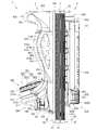
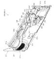
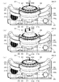
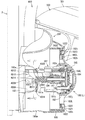
まず、図1乃至図12を参照してパチンコ機1の全体構成について説明する。図1はパチンコ機の正面図である。図2はパチンコ機の右側面図であり、図3はパチンコ機の左側面図であり、図4はパチンコ機の背面図である。図5はパチンコ機を右前から見た斜視図であり、図6はパチンコ機を左前から見た斜視図であり、図7はパチンコ機を後ろから見た斜視図である。図8は演出操作ユニットの押圧操作部が上昇位置の時のパチンコ機の正面図であり、図9は演出操作ユニットの押圧操作部が上昇位置の時のパチンコ機を右前から見た斜視図である。また、図10A、図10Bは、本体枠から扉枠を開放させると共に、外枠から本体枠を開放させた状態で前から見たパチンコ機の斜視図である。図11はパチンコ機を扉枠、遊技盤、本体枠、及び外枠に分解して前から見た分解斜視図であり、図12はパチンコ機を扉枠、遊技盤、本体枠、及び外枠に分解して後ろから見た分解斜視図である。
First, the overall configuration of the pachinko machine 1 will be described with reference to FIGS. FIG. 1 is a front view of a pachinko machine. 2 is a right side view of the pachinko machine, FIG. 3 is a left side view of the pachinko machine, and FIG. 4 is a rear view of the pachinko machine. 5 is a perspective view of the pachinko machine viewed from the right front, FIG. 6 is a perspective view of the pachinko machine viewed from the left front, and FIG. 7 is a perspective view of the pachinko machine viewed from the rear. FIG. 8 is a front view of the pachinko machine when the pressing operation unit of the effect operation unit is in the raised position, and FIG. 9 is a perspective view of the pachinko machine when the pressing operation unit of the effect operation unit is in the raised position as viewed from the right front. is there. 10A and 10B are perspective views of the pachinko machine viewed from the front with the door frame opened from the main body frame and the main body frame opened from the outer frame. 11 is an exploded perspective view of the pachinko machine as seen from the front after disassembling the door frame, game board, main body frame, and outer frame. FIG. 12 shows the pachinko machine as a door frame, game board, main body frame, and outer frame. It is the disassembled perspective view which decomposed | disassembled and was seen from the back.
パチンコ機1は、遊技ホールの島設備(図示しない)に設置される枠状の外枠2と、外枠2の前面を開閉可能に閉鎖する扉枠3と、扉枠3を開閉可能に支持していると共に外枠2に開閉可能に取付けられている本体枠4と、本体枠4に前側から着脱可能に取付けられると共に扉枠3を通して遊技者側から視認可能とされ遊技者によって遊技球B(図90を参照)が打込まれる遊技領域5aを有した遊技盤5と、を備えている。
The pachinko machine 1 supports a frame-shaped outer frame 2 installed in an island facility (not shown) of the game hall, a door frame 3 that closes the front of the outer frame 2 so as to be opened and closed, and a door frame 3 that can be opened and closed. A main body frame 4 that is attached to the outer frame 2 so as to be openable and closable, and a main body frame 4 that is detachably attached to the main body frame 4 and that is visible from the player side through the door frame 3. And a game board 5 having a game area 5a into which (see FIG. 90) is driven.
外枠2は、正面視の形状が上下に延びた四角形の枠に形成されている。外枠2は、左右に離間しており上下に延びている外枠左組立体10及び外枠右組立体20と、外枠左組立体10及び外枠右組立体20の上端同士を連結している外枠上部材30と、外枠左組立体10及び外枠右組立体20の下端同士を連結している外枠下組立体40と、外枠上部材30の上面左端に取付けられている外枠上ヒンジ組立体50と、外枠左組立体10の右側面下部と外枠下組立体40の上面左端に取付けられている外枠下ヒンジ部材60と、を備えている。
The outer frame 2 is formed in a rectangular frame whose shape in front view extends vertically. The outer frame 2 connects the upper ends of the outer frame left assembly 10 and the outer frame right assembly 20 that are spaced apart from each other and extend vertically, and the upper ends of the outer frame left assembly 10 and the outer frame right assembly 20. The outer frame upper member 30, the outer frame lower assembly 40 that connects the lower ends of the outer frame left assembly 10 and the outer frame right assembly 20, and the upper left end of the outer frame upper member 30. An outer frame upper hinge assembly 50, and a lower right side surface of the outer frame left assembly 10 and an outer frame lower hinge member 60 attached to the upper left end of the outer frame lower assembly 40.
外枠2は、パチンコ機1が設置される遊技ホールの島設備に取付けられ、外枠上ヒンジ組立体50と外枠下ヒンジ部材60とによって、本体枠4の本体枠上ヒンジ部材510と本体枠下ヒンジ組立体520とを同軸上で回転可能に支持して、本体枠4を正面視左側を中心にして前方へ開閉可能に取付けるためのものである。
The outer frame 2 is attached to the island facility of the game hall where the pachinko machine 1 is installed, and the main frame upper hinge member 510 and the main body of the main body frame 4 by the outer frame upper hinge assembly 50 and the outer frame lower hinge member 60. The lower frame hinge assembly 520 is rotatably supported on the same axis, and the main body frame 4 is attached so as to be openable and closable forward with the left side as viewed from the front.
また、扉枠3は、本体枠4を閉じた時に、外枠下組立体40が、本体枠4における基板ユニット620のスピーカユニット620aと協働して、本体枠スピーカ622のエンクロージャ624の一部を形成し、本体枠スピーカ622の後方へ出力されたサウンドを、位相反転させて前方へ放射することで、より重低音のサウンドを遊技者に聴かせることができるものである。
Further, the door frame 3 is configured such that when the main body frame 4 is closed, the outer frame lower assembly 40 cooperates with the speaker unit 620a of the board unit 620 in the main body frame 4 to form a part of the enclosure 624 of the main body frame speaker 622. The sound output to the rear of the main body frame speaker 622 is inverted in phase and radiated forward, so that the player can hear a deeper bass sound.
扉枠3は、遊技球Bが打込まれる遊技盤5の遊技領域5aを前側から視認可能に閉鎖し、遊技領域5a内に打込むための遊技球Bを貯留すると共に、貯留している遊技球Bを遊技領域5a内へ打込むために遊技者が操作する操作媒体たるハンドル182を備えているものである。また、扉枠3は、パチンコ機1の前面全体を装飾するものである。
The door frame 3 closes the game area 5a of the game board 5 into which the game ball B is to be visibly viewed from the front side, stores the game balls B to be shot into the game area 5a, and stores the stored games. A handle 182 is provided as an operation medium operated by the player to drive the ball B into the game area 5a. The door frame 3 decorates the entire front surface of the pachinko machine 1.
また、扉枠3は、ハンドル182とは別に遊技者が操作可能な演出操作部301を備えており、遊技者参加型演出が実行された際に、遊技者が演出操作部301を操作することで遊技者が演出に参加できるようになり、遊技球Bによる遊技に加えて、演出操作部301の操作によっても遊技者を楽しませることができるようにしている。
Further, the door frame 3 includes an effect operation unit 301 that can be operated by the player separately from the handle 182, and when the player participation type effect is executed, the player operates the effect operation unit 301. Thus, the player can participate in the production, and in addition to the game by the game ball B, the player can also be entertained by operating the production operation unit 301.
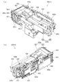
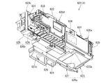
本体枠4は、後部が外枠2の枠内に挿入可能とされると共に遊技盤5の外周を支持可能とされた枠状の本体枠ベースユニット500と、本体枠4を外枠2に対して開閉可能に取付けると共に扉枠3を開閉可能に取付けるための本体枠上ヒンジ部材510及び本体枠下ヒンジ組立体520と、本体枠ベースユニット500を補強している本体枠補強フレーム530と、遊技盤5の遊技領域5a内に遊技球Bを打込むための球発射装置540と、遊技ホールの島設備から供給される遊技球Bを受取る払出ベースユニット550と、払出ベースユニット550で受取った遊技球Bを遊技者側へ払出すための払出ユニット560と、電源基板630や払出制御基板633を有している基板ユニット620と、本体枠ベース501に取付けられた遊技盤5の後側を覆う裏カバー640と、外枠2と本体枠4、及び扉枠3と本体枠4の間を施錠する施錠ユニット650と、を備えている。
The main body frame 4 has a frame-shaped main body frame base unit 500 whose rear portion can be inserted into the frame of the outer frame 2 and can support the outer periphery of the game board 5, and the main body frame 4 with respect to the outer frame 2. The main body frame upper hinge member 510 and the main body frame lower hinge assembly 520 for attaching the door frame 3 so that the door frame 3 can be opened and closed, the main body frame reinforcing frame 530 reinforcing the main body frame base unit 500, and the game A ball launcher 540 for driving the game ball B into the game area 5a of the board 5, a payout base unit 550 for receiving the game ball B supplied from the island facility of the game hall, and a game received by the payout base unit 550 A payout unit 560 for paying out the ball B to the player side, a board unit 620 having a power supply board 630 and a payout control board 633, and a game board attached to the main body frame base 501 A back cover 640 that covers the rear side of, and includes an outer frame 2 and the main frame 4, and the door frame 3 and the locking unit 650 for locking between the body frame 4, a.
本体枠4は、遊技球Bを打込むことで遊技が行われる遊技領域5aを有した遊技盤5を保持すると共に、遊技球Bを遊技者側へ払出したり、遊技に使用された遊技球Bをパチンコ機1の後方(遊技ホールの島設備側)へ排出したり、するためのものである。本体枠4は、前方が開放された箱状に形成されており、内部に前方から遊技盤5が着脱可能に収容される。また、本体枠4は、正面左辺側前端の上下において、遊技ホールの島設備に取付けられる枠状の外枠2に開閉可能に取付けられると共に、開放された前面側が閉鎖されるように扉枠3が開閉可能に取付けられる。
The main body frame 4 holds a game board 5 having a game area 5a in which a game is played by hitting the game ball B, and also pays out the game ball B to the player side or uses the game ball B used in the game. Is discharged to the rear of the pachinko machine 1 (island equipment side of the game hall). The main body frame 4 is formed in a box shape with the front opened, and a game board 5 is detachably accommodated therein from the front. In addition, the main body frame 4 is attached to the frame-like outer frame 2 attached to the island facility of the game hall at the top and bottom of the front left side front end so as to be openable and closable, and the door frame 3 is closed so that the opened front side is closed. Can be opened and closed.
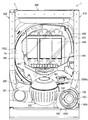
遊技盤5は、遊技者の操作によって遊技球Bが打ち込まれる遊技領域5aと、遊技領域5aの外周を区画し外形が正面視略四角形状とされた前構成部材1000と、前構成部材1000の後側に取付けられており遊技領域5aの後端を区画する板状の遊技パネル1100と、遊技パネル1100の後側下部に取付けられている基板ホルダ1200と、基板ホルダ1200の後面に取付けられており主制御基板1310を有している主制御ユニット1300と、主制御基板1310からの制御信号に基づいて遊技状況を表示する機能表示ユニット1400と、遊技パネル1100の後側に配置されている周辺制御ユニット1500と、正面視において遊技領域5aの中央に配置されており所定の演出画像を表示可能な演出表示装置1600と、遊技パネル1100の前面に取付けられる表ユニット2000と、遊技パネル1100の後面に取付けられる裏ユニット3000と、を備えている。裏ユニット3000には、遊技状態に応じて可動演出や発光演出を行うことが可能な裏演出ユニット3100を備えている。
The game board 5 includes a game area 5a into which a game ball B is driven by a player's operation, a front component member 1000 that defines the outer periphery of the game area 5a and has a substantially rectangular shape in front view, and a front component member 1000 A plate-like gaming panel 1100 that is attached to the rear side and divides the rear end of the gaming area 5a, a board holder 1200 that is attached to the lower rear side of the gaming panel 1100, and a board holder 1200 that is attached to the rear surface of the board holder 1200. A main control unit 1300 having a cage main control board 1310, a function display unit 1400 for displaying a game status based on a control signal from the main control board 1310, and a periphery disposed on the rear side of the game panel 1100 A control unit 1500, an effect display device 1600 that is arranged in the center of the game area 5a in a front view and can display a predetermined effect image; A table unit 2000 attached to the front surface of skill panel 1100, and a back unit 3000 attached to the rear surface of the gaming panel 1100, the. The back unit 3000 includes a back effect unit 3100 that can perform a movable effect and a light emission effect according to the gaming state.
遊技盤5の遊技領域5a内には、所定のゲージ配列で遊技パネル1100の前面に植設されていて遊技球Bの動きに変化を与える複数の障害釘2007と、遊技球Bの受け入れにより遊技者に対して所定の特典(例えば、所定数の遊技球Bの払出し)を付与する一般入賞口2001、第一始動口2002、第二始動口2004及び大入賞口2005等の受入口と、遊技球Bの通過により遊技者に対して所定の特典(例えば、第二始動口2004への入賞を所定時間可能にする。)を付与するゲート部2003と、遊技球Bが入球し得るもののそれによって利益がもたらされない不利な第1受入口2006(詳細については後述する。)が備えられている。この一般入賞口2001、第一始動口2002、ゲート部2003、第二始動口2004、大入賞口2005及び第1受入口2006は、表ユニット2000に備えられている。
In the game area 5 a of the game board 5, a plurality of obstacle nails 2007 that are implanted in front of the game panel 1100 with a predetermined gauge arrangement and change the movement of the game ball B, and a game by receiving the game ball B Receiving a predetermined privilege (for example, paying out a predetermined number of game balls B) to the player, such as a general winning port 2001, a first starting port 2002, a second starting port 2004, and a big winning port 2005, and a game A gate portion 2003 that gives a player a predetermined privilege (for example, allowing a player to win a second start opening 2004 for a predetermined time) by passing the ball B, and a game ball B that can enter the ball A disadvantageous first receiving port 2006 (details will be described later) is provided that does not provide any profit. The front winning unit 2001, the first starting port 2002, the gate unit 2003, the second starting port 2004, the big winning port 2005 and the first receiving port 2006 are provided in the front unit 2000.
遊技盤5の遊技領域5a内には、遊技者が遊技者操作用のハンドルユニット180を操作して打力調節という遊技用の入力をすることで、任意の強さで遊技球Bを打込むことができる。これにより遊技球Bを、遊技領域5a内の一般入賞口2001、第一始動口2002、ゲート部2003、第二始動口2004及び大入賞口2005等に受入れさせたり通過させ、不利な第1受入口2006へ入球させない、というように、遊技者に対してハンドル182の打込操作を楽しませることができる。
In the game area 5a of the game board 5, the player operates the player operation handle unit 180 and inputs a game ball for adjusting the hitting force, thereby driving the game ball B with an arbitrary strength. be able to. As a result, the game ball B is received or passed through the general winning port 2001, the first starting port 2002, the gate portion 2003, the second starting port 2004, the big winning port 2005, etc. in the gaming area 5a. The player can enter the operation of driving the handle 182 so as not to enter the entrance 2006.
また、遊技盤5は、遊技領域5a内に遊技球Bを打込むことで変化する遊技状態に応じて、演出表示装置1600に所定の演出画像を表示させたり、裏演出ユニット3100により可動演出や発光演出を行わせたりして、遊技者を楽しませることができる。
In addition, the game board 5 displays a predetermined effect image on the effect display device 1600 according to the game state that is changed by driving the game ball B into the game area 5a, The player can be entertained by performing a lighting effect.
パチンコ機1は、後述する上皿201に遊技球を貯留した状態で遊技者がハンドル182を回転操作すると、球発射装置540によってハンドル182の回転角度(ハンドル182の操作量)に応じた強さで遊技球が打ち出され、その遊技球が、発射レール544と外レール1001と内レール1002とによる発射通路部1012で形成された発射球通路を通って遊技盤5の遊技領域5a内へ案内される。そして、遊技領域5a内に打込まれた遊技球が、前記一般入賞口2001等に受入れられると、受入れられた入賞口に応じて、所定数の遊技球が後述する払出装置580によって球用開口から上皿201に払出される。
When the player rotates the handle 182 while a game ball is stored in the upper plate 201 described later, the pachinko machine 1 has a strength corresponding to the rotation angle of the handle 182 (the amount of operation of the handle 182) by the ball launcher 540. A game ball is launched, and the game ball is guided into the game area 5a of the game board 5 through the launch ball passage formed by the launch passage portion 1012 formed by the launch rail 544, the outer rail 1001, and the inner rail 1002. The Then, when the game ball that has been thrown into the game area 5a is received in the general winning opening 2001 or the like, a predetermined number of gaming balls are opened by the payout device 580 described later according to the received winning opening. To the upper plate 201.
なお、遊技球の打込強さ等の関係で、遊技領域5aに到達不能な強さ、つまり弱い発射力で発射された遊技球が遊技領域5a内に到達しなかった場合は、図10A、図37Aに示したように、発射レール544の端部(終端部)と外レール1001の端部(始端部)との間に開設されたファール球落下口1013に落下し、それが後述する返却通路部1014を構成するファールカバーユニット150のファール球受部150cに受けられ、ファールカバーユニット150内を通って球用開口たる下皿球供給口211cから下皿202に排出される。
Note that, in the case of the strength of the game ball 5a that cannot reach the game area 5a, that is, the game ball that has been launched with a weak launch force does not reach the game area 5a due to the game ball driving strength or the like, FIG. As shown in FIG. 37A, it falls on a foul ball drop opening 1013 established between the end portion (terminating portion) of the firing rail 544 and the end portion (starting end portion) of the outer rail 1001, and this is returned as described later. The ball is received by the foul ball receiving portion 150c of the foul cover unit 150 constituting the passage portion 1014, and is discharged to the lower plate 202 from the lower plate ball supply port 211c which is a ball opening through the foul cover unit 150.
[2.外枠の全体構成]
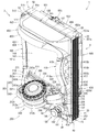
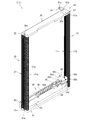
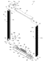
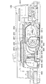
パチンコ機1の外枠2について、図13乃至図18を参照して説明する。図13はパチンコ機における外枠の正面図であり、図14は外枠の背面図であり、図15は外枠の右側面図である。また、図16は外枠を前から見た斜視図であり、図17は外枠を後ろから見た斜視図である。図18は、外枠を主な部材毎に分解して前から見た分解斜視図である。外枠2は、遊技ホール等のパチンコ機1が設置される島設備(図示は省略)に取付けられるものである。外枠2は、正面視の形状が上下に延びた四角形の枠に形成されている。
[2. Overall structure of outer frame]
The outer frame 2 of the pachinko machine 1 will be described with reference to FIGS. 13 to 18. 13 is a front view of the outer frame in the pachinko machine, FIG. 14 is a rear view of the outer frame, and FIG. 15 is a right side view of the outer frame. FIG. 16 is a perspective view of the outer frame as viewed from the front, and FIG. 17 is a perspective view of the outer frame as viewed from the rear. FIG. 18 is an exploded perspective view in which the outer frame is disassembled for each main member and viewed from the front. The outer frame 2 is attached to an island facility (not shown) where the pachinko machine 1 such as a game hall is installed. The outer frame 2 is formed in a rectangular frame whose shape in front view extends vertically.
外枠2は、図示するように、左右に離間しており上下に延びている外枠左組立体10及び外枠右組立体20と、外枠左組立体10及び外枠右組立体20の上端同士を連結している外枠上部材30と、外枠左組立体10及び外枠右組立体20の下端同士を連結している外枠下組立体40と、外枠上部材30の上面左端に取付けられている外枠上ヒンジ組立体50と、外枠左組立体10の右側面下部と外枠下組立体40の上面左端に取付けられている外枠下ヒンジ部材60と、を備えている。
As shown in the figure, the outer frame 2 includes an outer frame left assembly 10 and an outer frame right assembly 20 that are separated from each other and extend vertically, and an outer frame left assembly 10 and an outer frame right assembly 20. The outer frame upper member 30 that connects the upper ends, the outer frame lower assembly 40 that connects the lower ends of the outer frame left assembly 10 and the outer frame right assembly 20, and the upper surface of the outer frame upper member 30 An outer frame upper hinge assembly 50 attached to the left end, a lower right side surface of the outer frame left assembly 10, and an outer frame lower hinge member 60 attached to the upper left end of the outer frame lower assembly 40. ing.
外枠2は、本体枠4を閉じた時に、外枠下組立体40が、本体枠4における基板ユニット620のスピーカユニット620aと協働して、本体枠スピーカ622のエンクロージャ624の一部を形成していると共に、本体枠スピーカ622の後方へ出力されたサウンドを、位相反転させて前方へ放射することができるものである。
In the outer frame 2, when the main body frame 4 is closed, the outer frame lower assembly 40 forms a part of the enclosure 624 of the main body frame speaker 622 in cooperation with the speaker unit 620 a of the board unit 620 in the main body frame 4. In addition, the sound output to the rear of the main body frame speaker 622 can be radiated forward by phase inversion.
外枠2は、外枠上ヒンジ組立体50が、本体枠4の本体枠上ヒンジ部材510を着脱可能に支持することができる。外枠2は、外枠上ヒンジ組立体50と外枠下ヒンジ部材60とによって、本体枠4の本体枠上ヒンジ部材510と本体枠下ヒンジ組立体520とを同軸上で回転可能に支持することができ、本体枠4を正面視左側を中心にして前方へ開閉可能に取付けることができる。
In the outer frame 2, the outer frame upper hinge assembly 50 can detachably support the main body frame upper hinge member 510 of the main body frame 4. The outer frame 2 supports the main body frame upper hinge member 510 and the main body frame lower hinge assembly 520 of the main body frame 4 so as to be coaxially rotatable by the outer frame upper hinge assembly 50 and the outer frame lower hinge member 60. The main body frame 4 can be attached so as to be openable and closable forward with the left side of the front view as the center.
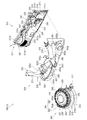
[2−1.外枠左組立体及び外枠右組立体]
外枠2の外枠左組立体10及び外枠右組立体20について、主に図19を参照して詳細に説明する。図19は、外枠の外枠左組立体及び外枠右組立体を夫々分解して前から見た分解斜視図である。外枠2の外枠左組立体10及び外枠右組立体20は、夫々が上下に延びており、互いに左右に離間して配置されている。外枠左組立体10及び外枠右組立体20は、本体枠4の本体枠上ヒンジ部材510及び本体枠下ヒンジ組立体520を同軸上で回転可能に支持して、外枠2に対して本体枠4を開閉可能に取付けるためのものである。
[2-1. Outer frame left assembly and outer frame right assembly]
The outer frame left assembly 10 and the outer frame right assembly 20 of the outer frame 2 will be described in detail mainly with reference to FIG. FIG. 19 is an exploded perspective view of the outer frame left assembly and the outer frame right assembly of the outer frame as seen from the front after disassembly. The outer frame left assembly 10 and the outer frame right assembly 20 of the outer frame 2 extend vertically and are spaced apart from each other on the left and right. The outer frame left assembly 10 and the outer frame right assembly 20 support the body frame upper hinge member 510 and the body frame lower hinge assembly 520 of the body frame 4 so as to be rotatable coaxially with respect to the outer frame 2. It is for attaching the main body frame 4 so that opening and closing is possible.
まず、外枠左組立体10は、前後方向が一定の幅(奥行)で上下に延びている外枠左部材11と、外枠左部材11の右側面上端に取付けられている左上連結部材12と、外枠左部材11の右側面下端に取付けられている左下連結部材13と、を備えている。
First, the outer frame left assembly 10 includes an outer frame left member 11 that extends vertically with a constant width (depth) in the front-rear direction, and an upper left connecting member 12 that is attached to the upper right side of the outer frame left member 11. And a lower left connecting member 13 attached to the lower end of the right side surface of the outer frame left member 11.
外枠左部材11は、一定の断面形状で上下に延びており、アルミ合金の押出型材によって形成されている。外枠左部材11は、左側面における前後方向を三等分したうちの後側の部位において平坦状に右方へ窪んでいる凹部11aと、右側面における凹部11aとは反対側の部位から右方へ膨出している膨出部11bと、膨出部11bを上下に貫通している空洞部11cと、を備えている。外枠左部材11は、凹部11aや膨出部11bによって、強度・剛性が高められていると共に、空洞部11cによって、重量が軽減されている。
The outer frame left member 11 extends vertically with a constant cross-sectional shape, and is formed of an extruded material of aluminum alloy. The outer frame left member 11 has a concave portion 11a that is flattened to the right in the rear portion of the left and right sides of the front and rear direction, and a right portion from a portion on the right side opposite to the concave portion 11a. A bulging portion 11b that bulges in the direction and a hollow portion 11c that penetrates the bulging portion 11b vertically. The outer frame left member 11 is enhanced in strength and rigidity by the concave portion 11a and the bulging portion 11b, and weight is reduced by the hollow portion 11c.
また、外枠左部材11は、左右両側面において、上下に延びた複数の溝が形成されている。左側面の複数の溝は、V字状に形成されており、右側面の複数の溝は、半円形状に形成されている。外枠左部材11は、後述する外枠右組立体20の外枠右部材21と左右対称形状に形成されている。
The outer frame left member 11 is formed with a plurality of grooves extending vertically on both left and right side surfaces. The plurality of grooves on the left side surface are formed in a V shape, and the plurality of grooves on the right side surface are formed in a semicircular shape. The outer frame left member 11 is formed symmetrically with an outer frame right member 21 of an outer frame right assembly 20 described later.
左上連結部材12は、外枠左部材11の上端と外枠上部材30の左端とを連結するためのものである。左上連結部材12は、水平に延びた平板状の水平固定部12aと、水平固定部12aの左辺における前後方向の中間から上方へ延出している平板状の上横固定部12bと、水平固定部12aの左辺における上横固定部12bの前後両側から下方へ延出している平板状の一対の下横固定部12cと、を備えている。左上連結部材12は、平板状の金属板を屈曲させて形成されている。
The upper left connecting member 12 is for connecting the upper end of the outer frame left member 11 and the left end of the outer frame upper member 30. The upper left connecting member 12 includes a horizontally extending flat plate-like horizontal fixing portion 12a, a flat upper plate fixing portion 12b extending from the middle in the front-rear direction on the left side of the horizontal fixing portion 12a, and a horizontal fixing portion. A pair of flat horizontal lower fixing portions 12c extending downward from both front and rear sides of the upper horizontal fixing portion 12b on the left side of 12a. The upper left connecting member 12 is formed by bending a flat metal plate.
左上連結部材12は、後側の下横固定部12cを外枠左部材11の空洞部11c内に挿入させると共に、水平固定部12aを外枠左部材11の上端に当接させ、更に、前側及び後側の下横固定部12cを外枠左部材11の右側面に当接させた状態で、外枠左部材11の左側面の外側から下横固定部12cにビスを捩じ込むことで、外枠左部材11に取付けられる。また、左上連結部材12は、水平固定部12aを外枠上部材30の左端側の下面に当接させると共に、上横固定部12bを外枠上部材30の左側面の切欠部30a内に挿入させた状態で、水平固定部12a及び上横固定部12bを通して外枠上部材30にビスを捩じ込むことで、外枠上部材30に取付けられる。
The upper left connecting member 12 has the rear lower horizontal fixing portion 12c inserted into the hollow portion 11c of the outer frame left member 11, the horizontal fixing portion 12a brought into contact with the upper end of the outer frame left member 11, and the front side Further, by screwing a screw into the lower horizontal fixing portion 12c from the outside of the left side surface of the outer frame left member 11 in a state where the rear lower fixing portion 12c is in contact with the right side surface of the outer frame left member 11. It is attached to the outer frame left member 11. In addition, the upper left connecting member 12 causes the horizontal fixing portion 12a to abut the lower surface of the outer frame upper member 30 on the left end side, and the upper horizontal fixing portion 12b is inserted into the left notch 30a of the outer frame upper member 30. In this state, the screw is screwed into the outer frame upper member 30 through the horizontal fixing portion 12a and the upper horizontal fixing portion 12b, so that the outer frame upper member 30 is attached.
左下連結部材13は、外枠左部材11の下端と外枠下組立体40(外枠下部材41)の左端とを連結するためのものである。左下連結部材13は、水平に延びた平板状の水平固定部13aと、水平固定部13aの左辺から上方へ延出していると共に水平固定部13aよりも後方へ延出している平板状の上横固定部13bと、上横固定部13bの下辺における水平固定部よりも後側の部位から下方へ延出している平板状の下横固定部13cと、上横固定部13bの後辺から右方へ短く延出している平板状の当接部13dと、を備えている。左下連結部材13は、平板状の金属板を屈曲させて形成されている。
The lower left connecting member 13 is for connecting the lower end of the outer frame left member 11 and the left end of the outer frame lower assembly 40 (outer frame lower member 41). The lower left connecting member 13 includes a horizontally extending flat plate-like horizontal fixing portion 13a, and a flat plate-like upper and horizontal portion extending upward from the left side of the horizontal fixing portion 13a and extending rearward from the horizontal fixing portion 13a. The fixing portion 13b, a flat plate-like lower horizontal fixing portion 13c extending downward from the rear side portion of the horizontal fixing portion on the lower side of the upper horizontal fixing portion 13b, and the right side from the rear side of the upper horizontal fixing portion 13b And a flat plate-like contact portion 13d extending short. The lower left connecting member 13 is formed by bending a flat metal plate.
左下連結部材13は、当接部13dの後面を外枠左部材11の膨出部11bの前面に当接させると共に、上横固定部13bの左側面を外枠左部材11の右側面に当接させ、水平固定部13aの下面を外枠左部材11の下端と一致させた状態で、外枠左部材11の左側面の外側から上横固定部13bにビスを捩じ込むことで、外枠左部材11に取付けられる。また、左下連結部材13は、水平固定部13aを外枠下部材41の左端側の上面に当接させると共に、下横固定部13cを外枠下部材41の左側面の切欠部41aに挿入させた状態で、水平固定部13a及び下横固定部13cを通して外枠下部材にビスを捩じ込むことで、外枠下部材41に取付けられる。
The lower left connecting member 13 abuts the rear surface of the abutting portion 13d on the front surface of the bulging portion 11b of the outer frame left member 11, and abuts the left side surface of the upper horizontal fixing portion 13b on the right side surface of the outer frame left member 11. The screw is screwed into the upper horizontal fixing portion 13b from the outside of the left side surface of the outer frame left member 11 in a state where the lower surface of the horizontal fixing portion 13a is aligned with the lower end of the outer frame left member 11, It is attached to the frame left member 11. The lower left connecting member 13 causes the horizontal fixing portion 13a to abut on the upper surface on the left end side of the outer frame lower member 41 and allows the lower horizontal fixing portion 13c to be inserted into the notch portion 41a on the left side surface of the outer frame lower member 41. In this state, the screw is screwed into the outer frame lower member through the horizontal fixing portion 13a and the lower horizontal fixing portion 13c, thereby being attached to the outer frame lower member 41.
次に、外枠右組立体20は、前後方向が一定の幅(奥行)で上下に延びている外枠右部材21と、外枠右部材21の左側面上端に取付けられている右上連結部材22と、外枠右部材21の左側面下端に取付けられている右下連結部材23と、外枠右部材21の左側面上部に取付けられている上鉤掛部材24と、外枠右部材21の左側面下部に取付けられている下鉤掛部材25と、を備えている。
Next, the outer frame right assembly 20 includes an outer frame right member 21 that extends vertically with a constant width (depth) in the front-rear direction, and an upper right connecting member that is attached to the upper left end of the outer frame right member 21. 22, a lower right connecting member 23 attached to the lower left side lower end of the outer frame right member 21, an upper hook member 24 attached to the upper left side of the outer frame right member 21, and the outer frame right member 21. And a lower hook member 25 attached to the lower part of the left side surface.
外枠右部材21は、一定の断面形状で上下に延びており、アルミ合金の押出型材によって形成されている。外枠右部材21は、右側面における前後方向を三等分したうちの後側の部位において平坦状に左方へ窪んでいる凹部21aと、左側面における凹部21aとは反対側の部位から左方へ膨出している膨出部21bと、膨出部21bを上下に貫通している空洞部21cと、を備えている。外枠右部材21は、凹部21aや膨出部21bによって、強度・剛性が高められていると共に、空洞部21cによって、重量が軽減されている。
The outer frame right member 21 extends vertically with a constant cross-sectional shape, and is formed of an aluminum alloy extrusion mold. The outer frame right member 21 has a concave portion 21a that is recessed leftward in a flat shape in a rear portion of the right and left sides of the front and rear direction, and a left portion from a portion on the left side opposite to the concave portion 21a. A bulging portion 21b that bulges in the direction, and a hollow portion 21c that vertically penetrates the bulging portion 21b. The outer frame right member 21 is increased in strength and rigidity by the concave portion 21a and the bulging portion 21b, and the weight is reduced by the hollow portion 21c.
また、外枠右部材21は、左右両側面において、上下に延びた複数の溝が形成されている。右側面の複数の溝は、V字状に形成されており、左側面の複数の溝は、半円形状に形成されている。外枠右部材21は、外枠左組立体10の外枠左部材11と左右対称形状に形成されている。
The outer frame right member 21 has a plurality of grooves extending vertically on both left and right side surfaces. The plurality of grooves on the right side surface are formed in a V shape, and the plurality of grooves on the left side surface are formed in a semicircular shape. The outer frame right member 21 is formed symmetrically with the outer frame left member 11 of the outer frame left assembly 10.
右上連結部材22は、外枠右部材21の上端と外枠上部材30の右端とを連結するためのものである。右上連結部材22は、水平に延びた平板状の水平固定部22aと、水平固定部22aの右辺における前後方向の中間から上方へ延出している平板状の上横固定部22bと、水平固定部22aの右辺における上横固定部22bの前後両側から下方へ延出している平板状の一対の下横固定部22cと、を備えている。右上連結部材22は、平板状の金属板を屈曲させて形成されている。
The upper right connecting member 22 is for connecting the upper end of the outer frame right member 21 and the right end of the outer frame upper member 30. The upper right connecting member 22 includes a horizontally extending flat plate-like horizontal fixing portion 22a, a flat upper plate fixing portion 22b extending from the middle in the front-rear direction on the right side of the horizontal fixing portion 22a, and a horizontal fixing portion. A pair of flat horizontal lower fixing portions 22c extending downward from both front and rear sides of the upper horizontal fixing portion 22b on the right side of 22a. The upper right connecting member 22 is formed by bending a flat metal plate.
右上連結部材22は、後側の下横固定部22cを外枠右部材21の空洞部21c内に挿入させると共に、水平固定部22aを外枠右部材21の上端に当接させ、更に、前側及び後側の下横固定部22cを外枠右部材21の左側面に当接させた状態で、外枠右部材21の右側面の外側から下横固定部22cにビスを捩じ込むことで、外枠右部材21に取付けられる。また、右上連結部材22は、水平固定部22aを外枠上部材30の右端側の下面に当接させると共に、上横固定部22bを外枠上部材30の右側面の切欠部30a内に挿入させた状態で、水平固定部22a及び上横固定部22bを通して外枠上部材30にビスを捩じ込むことで、外枠上部材30に取付けられる。
The upper right connecting member 22 has the rear lower horizontal fixing portion 22c inserted into the hollow portion 21c of the outer frame right member 21, the horizontal fixing portion 22a abutted against the upper end of the outer frame right member 21, and the front side Further, by screwing a screw into the lower horizontal fixing portion 22c from the outside of the right side surface of the outer frame right member 21 in a state where the rear lower fixing portion 22c is in contact with the left side surface of the outer frame right member 21. The outer frame right member 21 is attached. Further, the upper right connecting member 22 makes the horizontal fixing portion 22a abut on the lower surface on the right end side of the outer frame upper member 30, and the upper horizontal fixing portion 22b is inserted into the notch portion 30a on the right side surface of the outer frame upper member 30. In this state, the screw is screwed into the outer frame upper member 30 through the horizontal fixing portion 22a and the upper horizontal fixing portion 22b, thereby being attached to the outer frame upper member 30.
右下連結部材23は、外枠右部材21の下端と外枠下組立体40(外枠下部材41)の右端とを連結するためのものである。右下連結部材23は、水平に延びた平板状の水平固定部23aと、水平固定部23aの右辺から上方へ延出していると共に水平固定部23aよりも後方へ延出している平板状の上横固定部23bと、上横固定部23bの下辺における水平固定部よりも後側の部位から下方へ延出している平板状の下横固定部23cと、上横固定部23bの後辺から左方へ短く延出している平板状の当接部23dと、を備えている。右下連結部材23は、平板状の金属板を屈曲させて形成されている。
The lower right connecting member 23 is for connecting the lower end of the outer frame right member 21 and the right end of the outer frame lower assembly 40 (outer frame lower member 41). The lower right connecting member 23 includes a horizontally extending flat plate-like horizontal fixing portion 23a, and a flat plate-like upper portion extending upward from the right side of the horizontal fixing portion 23a and extending backward from the horizontal fixing portion 23a. The horizontal fixing portion 23b, a flat plate-like lower horizontal fixing portion 23c extending downward from a portion behind the horizontal fixing portion on the lower side of the upper horizontal fixing portion 23b, and a left side from the rear side of the upper horizontal fixing portion 23b A flat plate-like abutting portion 23d extending short in the direction. The lower right connecting member 23 is formed by bending a flat metal plate.
右下連結部材23は、当接部23dの後面を外枠右部材21の膨出部21bの前面に当接させると共に、上横固定部23bの右側面を外枠右部材21の左側面に当接させ、水平固定部23aの下面を外枠右部材21の下端と一致させた状態で、外枠右部材21の右側面の外側から上横固定部23bにビスを捩じ込むことで、外枠右部材21に取付けられる。また、右下連結部材23は、水平固定部23aを外枠下部材41の右端側の上面に当接させると共に、下横固定部23cを外枠下部材41の右側面の切欠部41aに挿入させた状態で、水平固定部23a及び下横固定部23cを通して外枠下部材にビスを捩じ込むことで、外枠下部材41に取付けられる。
The lower right connecting member 23 abuts the rear surface of the abutting portion 23d on the front surface of the bulging portion 21b of the outer frame right member 21, and the right side surface of the upper lateral fixing portion 23b on the left side surface of the outer frame right member 21. The screw is screwed into the upper lateral fixing portion 23b from the outside of the right side surface of the outer frame right member 21 with the lower surface of the horizontal fixing portion 23a being in contact with the lower end of the outer frame right member 21, It is attached to the outer frame right member 21. Further, the lower right connecting member 23 causes the horizontal fixing portion 23a to abut on the upper surface on the right end side of the outer frame lower member 41, and the lower horizontal fixing portion 23c is inserted into the cutout portion 41a on the right side surface of the outer frame lower member 41. In this state, the screw is screwed into the outer frame lower member through the horizontal fixing portion 23a and the lower horizontal fixing portion 23c, thereby being attached to the outer frame lower member 41.
上鉤掛部材24及び下鉤掛部材25は、後述する本体枠4における施錠ユニット650の外枠用鉤653が掛止されるものである。上鉤掛部材24は、前後方向に一定の幅で上下に延びており外枠右部材21の左側面に取付けられる平板状の取付部24aと、取付部24aの前辺から左方へ延出しており上側の外枠用鉤653が掛止される平板状の掛止片部24bと、を備えている。
The upper hook member 24 and the lower hook member 25 are for hooking an outer frame hook 653 of the locking unit 650 in the main body frame 4 described later. The upper hook member 24 extends vertically with a constant width in the front-rear direction, and is attached to the left side surface of the outer frame right member 21 and extends leftward from the front side of the attachment portion 24a. And a flat plate-like hooking piece 24b on which the outer upper frame flange 653 is hooked.
下鉤掛部材25は、前後方向に一定の幅で上下に延びており外枠右部材21の左側面に取付けられる平板状の取付部25aと、取付部25aの前辺から左方へ延出しており下側の外枠用鉤653が掛止される平板状の掛止片部25bと、掛止片部25bを前後に貫通しており下側の外枠用鉤653が挿通可能な挿通口25cと、を備えている。
The lower hook member 25 extends vertically with a certain width in the front-rear direction, and is attached to the left side surface of the outer frame right member 21 and extends leftward from the front side of the attachment portion 25a. A flat plate-like latching piece 25b to which the lower outer frame hook 653 is hooked, and an insertion through which the lower outer frame hook 653 can be inserted through the hooking piece 25b in the front-rear direction And a mouth 25c.
[2−2.外枠上部材]
外枠2の外枠上部材30について、主に図18を参照して詳細に説明する。外枠上部材30は、左右に離間している外枠左組立体10及び外枠右組立体20の上端同士を連結するためのものである。外枠上部材30は、前後方向の幅が、外枠左部材11及び外枠右部材21の前後方向と略同じ幅で、上下方向の厚さが一定で、左右方向に延びており、木材によって形成されている。外枠上部材30は、左右方向の長さが、後述する外枠下組立体40の外枠下部材41の左右方向の長さと同じに形成されている。
[2-2. Outer frame member]
The outer frame upper member 30 of the outer frame 2 will be described in detail mainly with reference to FIG. The outer frame upper member 30 is for connecting the upper ends of the outer frame left assembly 10 and the outer frame right assembly 20 that are separated from each other in the left-right direction. The outer frame upper member 30 has a width in the front-rear direction that is substantially the same as the front-rear direction of the outer frame left member 11 and the outer frame right member 21, has a constant vertical thickness, and extends in the left-right direction. Is formed by. The outer frame upper member 30 is formed so that the length in the left-right direction is the same as the length in the left-right direction of the outer frame lower member 41 of the outer frame lower assembly 40 described later.
外枠上部材30は、左右両側面における前後方向の中央において、上下に貫通した状態で左右方向中央側へ夫々窪んでいる切欠部30aを備えている。これら左右両端の切欠部30aには、左上連結部材12の上横固定部12b及び右上連結部材22の上横固定部22bが夫々挿入された状態で取付けられる。
The outer frame upper member 30 includes notches 30a that are recessed toward the center in the left-right direction in a state of penetrating vertically in the center in the front-rear direction on both left and right side surfaces. The upper horizontal fixing portion 12b of the upper left connecting member 12 and the upper horizontal fixing portion 22b of the upper right connecting member 22 are respectively attached to the cutout portions 30a at both left and right ends.
また、外枠上部材30は、左側端部において、上面と前面が一般面よりも窪んだ取付段部30bを備えている。この取付段部30bには、後述する外枠上ヒンジ組立体50が取付けられる。
Further, the outer frame upper member 30 includes an attachment step portion 30b whose upper surface and front surface are recessed from the general surface at the left end. The outer frame hinge assembly 50 described later is attached to the attachment step 30b.
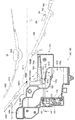
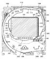
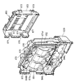
[2−3.外枠下組立体]
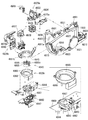
外枠2の外枠下組立体40について、主に図20を参照して詳細に説明する。図20は、外枠の外枠下組立体を分解して前から見た分解斜視図である。外枠下組立体40は、左右に離間している外枠左組立体10及び外枠右組立体20の下端同士を連結すると共に、パチンコ機1において扉枠3よりも下側を閉鎖して装飾するためのものである。
[2-3. Outer frame assembly]
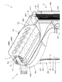
The outer frame lower assembly 40 of the outer frame 2 will be described in detail mainly with reference to FIG. FIG. 20 is an exploded perspective view of the outer frame lower assembly of the outer frame as seen from the front. The outer frame lower assembly 40 connects the lower ends of the outer frame left assembly 10 and the outer frame right assembly 20 that are separated from each other to the left and right, and closes the lower side of the door frame 3 in the pachinko machine 1. It is for decoration.
外枠下組立体40は、左右に離間している外枠左組立体10及び外枠右組立体20の下端同士を連結しており左右に延びている外枠下部材41と、外枠下部材41の前方に配置されており外枠下部材41に沿って左右に延びていると共に後方が開放されている箱状の幕板前部材42と、幕板前部材42の後側に取付けられていると共に外枠下部材41の上面に取付けられており前方が開放されている左右に延びた箱状の幕板後部材43と、幕板後部材43の上面における左端に形成されている球噛防止機構44と、を備えている。
The outer frame lower assembly 40 connects the lower ends of the outer frame left assembly 10 and the outer frame right assembly 20 which are separated from each other to the left and right, and an outer frame lower member 41 extending left and right. A box-shaped curtain plate front member 42 that is disposed in front of the member 41, extends left and right along the outer frame lower member 41, and is open to the rear, and is attached to the rear side of the curtain plate front member 42. A box-shaped curtain plate rear member 43 that is attached to the upper surface of the outer frame lower member 41 and that extends to the left and right, and a ball engagement prevention formed at the left end of the upper surface of the curtain plate rear member 43. And a mechanism 44.
外枠下部材41は、前後方向の幅が、外枠左部材11及び外枠右部材21の前後方向と略同じ幅で、上下方向の厚さが一定で、左右方向に延びており、木材によって形成されている。外枠下部材41は、左右方向の長さが、外枠上部材30の左右方向の長さと同じに形成されている。
The outer frame lower member 41 has a width in the front-rear direction that is substantially the same as the front-rear direction of the outer frame left member 11 and the outer frame right member 21, has a constant vertical thickness, and extends in the left-right direction. Is formed by. The outer frame lower member 41 is formed to have the same length in the left-right direction as the length of the outer frame upper member 30 in the left-right direction.
外枠下部材41は、左右両側面における前後方向の中央において、上下に貫通した状態で左右方向中央側へ夫々窪んでいる切欠部41aを備えている。これら左右両端の切欠部41aには、左下連結部材13の下横固定部13c及び右下連結部材23の下横固定部23cが夫々挿入された状態で取付けられる。これにより、外枠左部材11及び外枠右部材21の下端同士を連結することができる。
The outer frame lower member 41 includes notches 41a that are recessed toward the center in the left-right direction in a state of penetrating vertically in the center in the front-rear direction on both left and right side surfaces. The left and right cutouts 41a are attached with the lower horizontal fixing portion 13c of the lower left connecting member 13 and the lower horizontal fixing portion 23c of the lower right connecting member 23 inserted respectively. Thereby, the lower ends of the outer frame left member 11 and the outer frame right member 21 can be connected to each other.
また、外枠下部材41は、上面から凹んでおり、幕板後部材43の下部が挿入される凹部41bを備えている。凹部41bは、左右に延びていると共に、前後方向中央の後ろ寄りの位置から前端側へ抜けている。この凹部41bにより、幕板前部材42及び幕板後部材43により形成される幕板内部空間40aの容積を可及的に広くしている。
Further, the outer frame lower member 41 is recessed from the upper surface and includes a recess 41b into which the lower part of the curtain plate rear member 43 is inserted. The concave portion 41b extends to the left and right, and extends from the position closer to the rear of the center in the front-rear direction to the front end side. By this recess 41b, the volume of the curtain plate internal space 40a formed by the curtain plate front member 42 and the curtain plate rear member 43 is made as large as possible.
幕板前部材42は、左右方向の長さが外枠下部材41と同じ長さに延びており、高さに対して前後方向の奥行が短い横長の直方体状の箱状に形成されており、後側の全面が開放されている。幕板前部材42は、開放されている後側を、幕板後部材43によって閉鎖することで、幕板後部材43と協働して本体枠スピーカ622のエンクロージャ624の一部となる幕板内部空間40aを形成する。幕板前部材42は、右端付近の前面において、前後に貫通していると共に左右に延びている長孔状の開口部42aを備えている。
The curtain plate front member 42 has a lateral length that is the same as the length of the outer frame lower member 41, and is formed in a horizontally-long rectangular parallelepiped box shape whose depth in the front-rear direction is short with respect to the height. The entire rear side is open. The curtain plate front member 42 closes the opened rear side by the curtain plate rear member 43, thereby cooperating with the curtain plate rear member 43 to be a part of the enclosure 624 of the main body frame speaker 622. A space 40a is formed. The curtain plate front member 42 is provided with a long hole-like opening 42a that penetrates in the front-rear direction and extends to the left and right in the front surface near the right end.
幕板後部材43は、左右方向の長さが外枠下部材41よりも若干短く延びており、前方が開放された箱状に形成されている。幕板後部材43は、前面に幕板前部材42を取付けることで、幕板前部材42と協働して本体枠スピーカ622のエンクロージャ624の一部となる幕板内部空間40aを形成する。幕板後部材43は、上面における左右方向中央部において、左右に延びていると共に上方へ突出しており幕板内部空間40aと連通している筒状の接続筒部43aを有している。接続筒部43aは、上端が、幕板後部材43の一般的な上面と一致している前端側から後方へ向かうほど上方へ位置するように傾斜している。本形態では、接続筒部43aの上端は、45度の角度で傾斜している。
The curtain plate rear member 43 has a length in the left-right direction that is slightly shorter than the outer frame lower member 41, and is formed in a box shape with the front open. The curtain plate rear member 43 has a curtain plate front member 42 attached to the front surface to form a curtain plate internal space 40a that becomes a part of the enclosure 624 of the body frame speaker 622 in cooperation with the curtain plate front member 42. The curtain plate rear member 43 has a cylindrical connecting cylinder portion 43a that extends in the left and right direction and protrudes upward at the center portion in the horizontal direction on the upper surface and communicates with the curtain plate internal space 40a. The connecting cylinder portion 43a is inclined so that the upper end is positioned upward as it goes rearward from the front end side that coincides with the general upper surface of the curtain plate rear member 43. In the present embodiment, the upper end of the connection cylinder portion 43a is inclined at an angle of 45 degrees.
この接続筒部43aは、左右方向の長さが、幕板後部材43全体の約1/3の長さに形成されていると共に、前後方向の奥行が、幕板後部材43全体の奥行よりも若干短く形成されている。接続筒部43a内には、前端側と後端側とを結ぶ複数のリブ43bが備えられている。この接続筒部43aの上端には、外枠2に対して本体枠4を閉じた時に、本体枠4における基板ユニット620のスピーカユニット620aにおけるスピーカカバー621の接続部621cが接続されて、スピーカユニット620aの内部空間と連通した状態となり、エンクロージャ624を形成する。
The connecting cylinder portion 43a is formed so that the length in the left-right direction is about 1/3 of the entire curtain plate rear member 43, and the depth in the front-rear direction is larger than the depth of the entire curtain plate rear member 43. Is also slightly shorter. A plurality of ribs 43b connecting the front end side and the rear end side are provided in the connection cylinder portion 43a. When the main body frame 4 is closed with respect to the outer frame 2, the connection portion 621c of the speaker cover 621 of the substrate unit 620 of the main body frame 4 is connected to the upper end of the connection cylinder portion 43a. The enclosure 624 is formed in communication with the internal space of 620a.
球噛防止機構44は、幕板後部材43の上面における左端において、外枠下ヒンジ部材60の部位に遊技球Bが滞留することで、外枠2と本体枠4との間に遊技球Bが挟まれるのを防止するためのものである。
The ball biting prevention mechanism 44 is configured such that the game ball B stays at a portion of the outer frame lower hinge member 60 at the left end on the upper surface of the curtain plate rear member 43, so that the game ball B is between the outer frame 2 and the main body frame 4. This is to prevent pinching.
球噛防止機構44は、幕板後部材43の上面における左端に形成されており、後述する外枠下ヒンジ部材60が際されるように平坦に形成された載置部44aと、載置部44aの左端において上方へ向かって開口している第一排出口44bと、載置部44aにおける第一排出口44bよりも右方で上方へ向かって開口している第二排出口44cと、載置部44aの後辺及び右辺から上方へ延出している立壁部44dと、立壁部44dの上端から前方へ突出していると共に上面が後方へ向かうに従って上方に位置するように傾斜している上端突出部44eと、を備えている。
The ball biting prevention mechanism 44 is formed at the left end on the upper surface of the curtain plate rear member 43, and a mounting portion 44a formed flat so that an outer frame lower hinge member 60 described later is confronted, and a mounting portion A first discharge port 44b that opens upward at the left end of 44a, a second discharge port 44c that opens upward to the right of the first discharge port 44b in the mounting portion 44a, A standing wall portion 44d extending upward from the rear side and the right side of the mounting portion 44a, and an upper end protrusion that protrudes forward from the upper end of the standing wall portion 44d and is inclined so that the upper surface is positioned upward as it goes rearward. Part 44e.
第一排出口44bは、後述する外枠下ヒンジ部材60の排出孔60dと一致する位置に形成されている。第一排出口44b及び第二排出口44cは、遊技球Bが通過可能な大きさに形成されている。第一排出口44b及び第二排出口44cは、幕板内部空間40aとは連通しておらず、幕板後部材43の後面に開口している。従って、第一排出口44b及び第二排出口44cに進入した遊技球Bを、幕板後部材43の後方へ排出することができる。
The 1st discharge port 44b is formed in the position which corresponds with the discharge hole 60d of the outer frame lower hinge member 60 mentioned later. The 1st discharge port 44b and the 2nd discharge port 44c are formed in the magnitude | size which the game ball B can pass. The first discharge port 44 b and the second discharge port 44 c do not communicate with the curtain plate internal space 40 a and are opened on the rear surface of the curtain plate rear member 43. Therefore, the game ball B that has entered the first discharge port 44 b and the second discharge port 44 c can be discharged to the rear of the curtain plate rear member 43.
この球噛防止機構44は、球噛防止機構44は、外枠下ヒンジ部材60と後述する本体枠下ヒンジ組立体520との間の隙間を通して、ピアノ線等の不正な工具が挿入された場合、載置部44aの後端から立上っている立壁部44dにより、不正な工具の侵入を阻止することができる。仮に、不正な工具の先端が立壁部44dに当接することで、上方へ曲がったとしても、立壁部44dの上端に備えられている前方へ突出した上端突出部44eに当接し、これ以上の侵入を阻止することができる。従って、外枠下ヒンジ部材60の部位を介して、不正行為が行われるのを防止することができる。
This ball biting prevention mechanism 44 is a case where an illegal tool such as a piano wire is inserted through a gap between the outer frame lower hinge member 60 and a main body frame lower hinge assembly 520 described later. Intrusion of an unauthorized tool can be prevented by the standing wall portion 44d rising from the rear end of the placement portion 44a. Even if the tip of an unauthorized tool contacts the standing wall 44d and bends upward, it contacts the upper end protruding part 44e provided at the upper end of the standing wall 44d and further intrudes. Can be prevented. Therefore, it is possible to prevent an illegal act from being performed through the portion of the outer frame lower hinge member 60.
ところで、載置部44aの後端に立壁部44dを備えた場合、外枠2に対して本体枠4を開けた時に、何らかの理由により載置部44a上に落下した遊技球Bが、立壁部44dによって外枠2の後方への移動が阻止されるため、載置部44a上に遊技球Bが滞留し易くなる。そして、載置部44a上に遊技球Bが滞留していると、外枠2に対して本体枠4を閉じる際に、外枠2と本体枠4との間に遊技球Bが挟み込まれてしまい、本体枠4を閉じることができなくなる問題が発生する。
By the way, when the standing wall portion 44d is provided at the rear end of the placement portion 44a, when the main body frame 4 is opened with respect to the outer frame 2, the game ball B dropped on the placement portion 44a for some reason is Since the rearward movement of the outer frame 2 is prevented by 44d, the game ball B is likely to stay on the placement portion 44a. If the game ball B stays on the mounting portion 44 a, the game ball B is sandwiched between the outer frame 2 and the main body frame 4 when the main body frame 4 is closed with respect to the outer frame 2. Therefore, there arises a problem that the main body frame 4 cannot be closed.
これに対して、本形態の球噛防止機構44では、外枠下ヒンジ部材60上や載置部44a上に落下した遊技球Bを、外枠下ヒンジ部材60の排出孔60dと第一排出口44bを通して、又は、第二排出口44cを通して、遊技球Bを幕板後部材43の後方(外枠2の後方)へ排出することができ、外枠2と本体枠4との間に遊技球Bが挟まれるのを防止することができる。
On the other hand, in the ball biting prevention mechanism 44 of the present embodiment, the game ball B dropped on the outer frame lower hinge member 60 or the placement portion 44a is transferred to the discharge hole 60d of the outer frame lower hinge member 60 and the first discharge. The game ball B can be discharged to the rear of the curtain plate rear member 43 (rear of the outer frame 2) through the outlet 44b or the second discharge port 44c, and between the outer frame 2 and the main body frame 4 It is possible to prevent the sphere B from being caught.
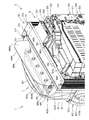
外枠下組立体40は、幕板前部材42及び幕板後部材43の上面に左右に離間して配置されている一対の案内部材45と、幕板前部材42の開口部42aを後側から閉鎖している平板状のグリル部材46と、グリル部材46を挟んで開口部42aを閉鎖するように幕板前部材42の内部に取付けられており前後に延びた二つの円筒を有したポート部材47と、幕板後部材43の接続筒部43aの上端に配置される枠状のシール部材48と、を備えている。
The outer frame lower assembly 40 closes the pair of guide members 45 disposed on the upper surfaces of the curtain plate front member 42 and the curtain plate rear member 43 so as to be separated from each other on the left and right sides, and the opening 42a of the curtain plate front member 42 from the rear side. A flat grill member 46, and a port member 47 having two cylinders attached to the front of the curtain plate front member 42 so as to close the opening 42a across the grill member 46 and extending in the front-rear direction. And a frame-shaped seal member 48 disposed at the upper end of the connecting tube portion 43a of the curtain plate rear member 43.
一対の案内部材45は、外枠2に対して本体枠4を閉じた時に、扉枠3の下端が当接するものである。案内部材45は、摩擦抵抗の低い低摩擦材料によって形成されており、本体枠4の下端を滑り易くして、開閉を容易にしている。
The pair of guide members 45 are configured such that the lower end of the door frame 3 comes into contact with the outer frame 2 when the main body frame 4 is closed. The guide member 45 is made of a low friction material having a low frictional resistance, and makes the lower end of the main body frame 4 easy to slide to facilitate opening and closing.
グリル部材46は、無数の小穴を有したパンチングメタルにより形成されている。ポート部材47は、二つの円筒により、グリル部材46を介して幕板内部空間40a(エンクロージャ624)と外枠2の前方とを連通させている。ポート部材47は、二つの円筒が、所定の内径で所定の長さに形成されており、ヘルムホルツ共鳴の原理により本体枠スピーカ622から後方(エンクロージャ624内)へ発せられた低音を共振・増幅させて、豊かな低音を外枠2の前方(遊技者側)へ放射することができる。つまり、本形態では、本体枠スピーカ622のエンクロージャ624がバスレフ型とされており、遊技者に対して重低音を聞かせることができる。
The grill member 46 is formed of a punching metal having innumerable small holes. The port member 47 communicates the curtain plate inner space 40 a (enclosure 624) and the front of the outer frame 2 through the grill member 46 by two cylinders. The port member 47 has two cylinders that are formed with a predetermined inner diameter and a predetermined length. The port member 47 resonates and amplifies a bass sound emitted backward (inside the enclosure 624) from the main body frame speaker 622 based on the principle of Helmholtz resonance. Thus, a rich bass can be radiated to the front (player side) of the outer frame 2. That is, in this embodiment, the enclosure 624 of the main body frame speaker 622 is a bass reflex type, and a player can hear a heavy bass.
シール部材48は、外枠2に対して本体枠4を閉じた時に、接続筒部43aの上端と本体枠4におけるスピーカカバー621の接続部621cの下端との間に挟まれて圧縮されるものであり、接続筒部43aと接続部621cとの間からスピーカのエンクロージャ内の音が漏れるのを防止するものである。
When the main body frame 4 is closed with respect to the outer frame 2, the seal member 48 is sandwiched and compressed between the upper end of the connection cylinder portion 43 a and the lower end of the connection portion 621 c of the speaker cover 621 in the main body frame 4. This prevents the sound in the speaker enclosure from leaking from between the connection tube 43a and the connection 621c.
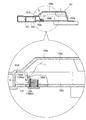
[2−4.外枠上ヒンジ組立体]
外枠2の外枠上ヒンジ組立体50について、主に図21を参照して詳細に説明する。図21(a)は外枠2の外枠上ヒンジ組立体を分解して前上から見た分解斜視図であり、(b)は(a)を前下から見た分解斜視図である。外枠上ヒンジ組立体50は、外枠左組立体10の上端と外枠上部材30の左端に取付けられるものであり、外枠2に対して本体枠4をヒンジ回転可能に取付けるためのものである。外枠上ヒンジ組立体50は、外枠左部材11の凹部11aの上端と外枠上部材30の取付段部30bとに取付けられる外枠上ヒンジ部材51と、外枠上ヒンジ部材51に取付けられているロック部材52と、ロック部材52を外枠上ヒンジ部材51に取付けている取付ビス53と、を備えている。
[2-4. Hinge assembly on outer frame]
The outer frame hinge assembly 50 of the outer frame 2 will be described in detail mainly with reference to FIG. FIG. 21A is an exploded perspective view of the outer frame hinge assembly of the outer frame 2 disassembled and viewed from the front top, and FIG. 21B is an exploded perspective view of FIG. The outer frame upper hinge assembly 50 is attached to the upper end of the outer frame left assembly 10 and the left end of the outer frame upper member 30, and is used to attach the main body frame 4 to the outer frame 2 so as to be rotatable. It is. The outer frame upper hinge assembly 50 is attached to the outer frame upper hinge member 51 attached to the upper end of the recess 11a of the outer frame left member 11 and the mounting step 30b of the outer frame upper member 30, and attached to the outer frame upper hinge member 51. And a mounting screw 53 that attaches the locking member 52 to the hinge member 51 on the outer frame.
外枠上ヒンジ部材51は、水平に延びた平板状で外枠上部材30の取付段部30bの上面に取付けられる上固定部51aと、上固定部51aの前辺から前方へ延出している平板状の前方延出部51bと、前方延出部51bの右辺の途中から前方へ向かうに従って前方延出部51bの左右中央へ延びており上下に貫通している軸受溝51cと、上固定部51aの左辺から下方へ延びている平板状の横固定部51dと、前方延出部51bの左辺から前辺を周って軸受溝51cが開口している部位までの端縁から下方へ延びており横固定部51dと連続している平板状の端縁壁部51eと、を備えている。外枠上ヒンジ部材51は、金属板をプレス成型により打抜き・屈曲させて形成されている。外枠上ヒンジ部材51は、軸受溝51c内において、本体枠上ヒンジ部材510の後述する本体枠上ヒンジピン512を回転可能に支持することができる。
The outer frame upper hinge member 51 is a flat plate extending horizontally, and is attached to the upper surface of the mounting step 30b of the outer frame upper member 30 and extends forward from the front side of the upper fixed portion 51a. A flat front extending portion 51b, a bearing groove 51c extending vertically from the middle of the right side of the front extending portion 51b to the front and penetrating vertically, and an upper fixing portion A flat plate-like lateral fixing portion 51d extending downward from the left side of 51a, and extending downward from an edge from the left side of the front extending portion 51b to the portion where the bearing groove 51c is opened around the front side. And a flat end edge wall portion 51e that is continuous with the cage lateral fixing portion 51d. The outer frame hinge member 51 is formed by punching and bending a metal plate by press molding. The outer frame hinge member 51 can rotatably support a body frame hinge pin 512, which will be described later, of the body frame hinge member 510 in the bearing groove 51c.
ロック部材52は、前後に延びている帯板状のロック本体52aと、ロック本体52aの後端から右方へ突出している操作片52bと、ロック本体52aの後端から左方へ延びた後に斜め左前方へ延びている弾性変形可能な棒状の弾性部52cと、ロック本体52aの後端付近で上下に貫通している取付孔52dと、を備えている。ロック部材52は、合成樹脂によって形成されている。ロック部材52は、取付ビス53によって、外枠上ヒンジ部材51における前方延出部51bの下面で、軸受溝51cよりも後側の部位に回動可能に取付けられる。
The lock member 52 includes a band-shaped lock body 52a extending in the front-rear direction, an operation piece 52b protruding rightward from the rear end of the lock body 52a, and extending leftward from the rear end of the lock body 52a. An elastically deformable rod-like elastic portion 52c extending obliquely left front and an attachment hole 52d penetrating vertically near the rear end of the lock body 52a are provided. The lock member 52 is made of synthetic resin. The lock member 52 is pivotally attached to the rear side of the bearing groove 51c on the lower surface of the front extending portion 51b of the outer frame upper hinge member 51 by the mounting screw 53.
ロック部材52は、外枠上ヒンジ部材51に取付けた状態で、ロック本体52aが、平面視で軸受溝51cを遮ることができると共に、前端付近の右側面が、外枠上ヒンジ部材51の端縁壁部51eにおける軸受溝51cの開口まで延びている部位と当接可能となるように前方へ延びている。また、ロック本体52aの後端から左方へ延びている弾性部52cの先端は、外枠上ヒンジ部材51における端縁壁部51eの内周面に当接している。このロック部材52は、弾性部52cの付勢力によって取付孔52dを中心に、前端が左方へ回動する方向に付勢されている。従って、通常の状態では、ロック部材52のロック本体52aの前端付近の右側面が、端縁壁部51eに当接している。この状態では、軸受溝51cにおけるロック本体52aよりも前側の部位に、本体枠上ヒンジ部材510の本体枠上ヒンジピン512を収容可能な空間が形成される。
When the lock member 52 is attached to the outer frame hinge member 51, the lock body 52a can block the bearing groove 51c in a plan view, and the right side surface near the front end is the end of the outer frame hinge member 51. The edge wall portion 51e extends forward so as to be able to come into contact with a portion extending to the opening of the bearing groove 51c. Further, the tip of the elastic portion 52 c extending leftward from the rear end of the lock main body 52 a is in contact with the inner peripheral surface of the edge wall portion 51 e of the outer frame upper hinge member 51. The lock member 52 is urged by the urging force of the elastic portion 52c in the direction in which the front end rotates leftward about the attachment hole 52d. Accordingly, in a normal state, the right side surface of the lock member 52 near the front end of the lock body 52a is in contact with the edge wall portion 51e. In this state, a space capable of accommodating the body frame upper hinge pin 512 of the body frame upper hinge member 510 is formed in a portion of the bearing groove 51c on the front side of the lock body 52a.
このロック部材52は、操作片52bを操作することで、弾性部52cの付勢力に抗してロック本体52aを回動させることができる。そして、操作片52bの操作によって、ロック本体52aを、その前端が左方へ移動する方向へ回動させることで、平面視において軸受溝51cからロック本体52aを後退させることができ、軸受溝51cが全通している状態とすることができる。これにより、軸受溝51c内に本体枠上ヒンジピン512を挿入したり、軸受溝51c内から本体枠上ヒンジピン512を外したりすることができる。
The lock member 52 can rotate the lock body 52a against the urging force of the elastic portion 52c by operating the operation piece 52b. Then, by operating the operation piece 52b, the lock body 52a is rotated in a direction in which the front end thereof moves to the left, whereby the lock body 52a can be retracted from the bearing groove 51c in a plan view, and the bearing groove 51c Can pass through. Thereby, the hinge pin 512 on the body frame can be inserted into the bearing groove 51c, or the hinge pin 512 on the body frame can be removed from the bearing groove 51c.
[2−5.外枠下ヒンジ部材]
外枠2の外枠下ヒンジ部材60について、主に図18を参照して詳細に説明する。外枠下ヒンジ部材60は、水平に延びた平板状の水平部60aと、水平部60aの左辺において前後方向中央よりも後側の部位から上方へ立上っている平板状の立上部60bと、水平部60aの前端付近から上方へ突出している外枠下ヒンジピン60cと、水平部60aを上下に貫通しており遊技球Bが一つのみ通過可能な大きさの排出孔60dと、を備えている。この外枠下ヒンジ部材60は、金属板をプレス成型により打抜き・屈曲させて形成されている。
[2-5. Outer frame lower hinge member]
The outer frame lower hinge member 60 of the outer frame 2 will be described in detail mainly with reference to FIG. The outer frame lower hinge member 60 includes a horizontally extending flat plate-like horizontal portion 60a, and a flat plate-like raised portion 60b that rises upward from a rear portion of the left side of the horizontal portion 60a with respect to the center in the front-rear direction. An outer frame lower hinge pin 60c projecting upward from the vicinity of the front end of the horizontal portion 60a, and a discharge hole 60d having a size penetrating the horizontal portion 60a vertically and allowing only one game ball B to pass therethrough. ing. The outer frame lower hinge member 60 is formed by punching and bending a metal plate by press molding.
外枠下ヒンジ部材60の水平部60aは、平面視において、左辺を底辺とした台形に形成されている。外枠下ヒンジピン60cは、円柱状で、上下方向中央よりも上部が、上端が窄まった円錐台状に形成されている。この外枠下ヒンジピン60cは、水平部60aの前端付近における左寄りの位置に取付けられている。排出孔60dは、水平部60aにおいて、立上部60bの前後方向中央の部位と接し、水平部60aの左辺から右方へ逆U字状に延びるように形成されている。この排出孔60dは、外枠下組立体40における球噛防止機構44の第一排出口44bと、略同じ大きさに形成されている。
The horizontal portion 60a of the outer frame lower hinge member 60 is formed in a trapezoidal shape with the left side as the bottom in plan view. The outer frame lower hinge pin 60c has a cylindrical shape, and is formed in a truncated cone shape whose upper end is narrower than the center in the vertical direction. The outer frame lower hinge pin 60c is attached to the left position near the front end of the horizontal portion 60a. In the horizontal portion 60a, the discharge hole 60d is in contact with the central portion in the front-rear direction of the upright portion 60b, and is formed to extend in an inverted U shape from the left side of the horizontal portion 60a to the right. The discharge hole 60d has substantially the same size as the first discharge port 44b of the ball engagement prevention mechanism 44 in the outer frame lower assembly 40.
外枠下ヒンジ部材60は、外枠2に組立てた状態で、水平部60aの後部が、外枠下組立体40における幕板後部材43の載置部44a上に載置され、図示しないビスによって幕板後部材43に固定されている。また、立上部60bが、外枠左部材11の右側面における膨出部11bよりも前側の部位に、図示しないビスによって取付けられている。この外枠下ヒンジ部材60は、外枠下ヒンジピン60cを、本体枠4の本体枠下ヒンジ組立体520における外枠用下ヒンジ孔521aに挿通させることで、外枠上ヒンジ部材51と協働して本体枠4を開閉可能に取付けることができる。
When the outer frame lower hinge member 60 is assembled to the outer frame 2, the rear portion of the horizontal portion 60 a is mounted on the mounting portion 44 a of the curtain plate rear member 43 in the outer frame lower assembly 40. Is fixed to the curtain plate rear member 43. Further, the upright portion 60b is attached to a portion of the right side surface of the outer frame left member 11 in front of the bulging portion 11b with a screw (not shown). The outer frame lower hinge member 60 cooperates with the outer frame upper hinge member 51 by inserting the outer frame lower hinge pin 60 c into the outer frame lower hinge hole 521 a in the main body frame lower hinge assembly 520 of the main body frame 4. Thus, the main body frame 4 can be attached so as to be opened and closed.
また、外枠2を組立てた状態では、排出孔60dが、外枠下組立体40における球噛防止機構44の第一排出口44bと一致している。これにより、水平部60a上の遊技球Bを、排出孔60d及び第一排出口44bを通して、外枠2の後方へ落下(排出)させることができる。詳述すると、外枠2に対して本体枠4を閉じる時に、外枠2と本体枠4との間に落下した遊技球Bが、本体枠4が閉じられるのに従って、外枠2と本体枠4との間が徐々に狭くなることから、間隔が広い後方側へ転動とすることとなり、排出孔60dから排出させることができる。この際に、排出孔60dが、パチンコ機1に組立てた状態で、外枠2に対して本体枠4を閉じた時に、本体枠4の後端と略同じとなる位置に形成されているため、外枠2と本体枠4との間に落下した遊技球Bを、排出孔60dから排出させることで本体枠4よりも後側へ転動するのを阻止し易くすることができ、外枠下ヒンジ部材60の部位に遊技球Bが留まり難くすることができる。
Further, in a state where the outer frame 2 is assembled, the discharge hole 60 d coincides with the first discharge port 44 b of the ball engagement prevention mechanism 44 in the outer frame lower assembly 40. Thereby, the game ball B on the horizontal portion 60a can be dropped (discharged) to the rear of the outer frame 2 through the discharge hole 60d and the first discharge port 44b. More specifically, when the main body frame 4 is closed with respect to the outer frame 2, the game balls B that have fallen between the outer frame 2 and the main body frame 4 are closed as the main body frame 4 is closed. 4 is gradually narrowed, so that the gap is rolled to the rear side with a wide interval, and can be discharged from the discharge hole 60d. At this time, the discharge hole 60d is formed at a position that is substantially the same as the rear end of the main body frame 4 when the main body frame 4 is closed with respect to the outer frame 2 in a state assembled to the pachinko machine 1. The game ball B dropped between the outer frame 2 and the main body frame 4 can be easily prevented from rolling to the rear side of the main body frame 4 by being discharged from the discharge hole 60d. It is possible to make it difficult for the game ball B to stay on the lower hinge member 60.
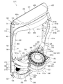
[3.扉枠の全体構成]
パチンコ機1の扉枠3について、主に図22乃至図30を参照して詳細に説明する。図22はパチンコ機における扉枠の表面図であり、図23は扉枠の背面図であり、図24は扉枠の左側面図であり、図25は扉枠の右側面図である。図26は扉枠を右前から見た斜視図であり、図27は扉枠を左前から見た斜視図であり、図28は扉枠を後ろから見た斜視図である。図29は扉枠を主な部材毎に分解して前から見た分解斜視図であり、図30は扉枠を主な部材毎に分解して後ろから見た分解斜視図である。
[3. Overall structure of door frame]
The door frame 3 of the pachinko machine 1 will be described in detail mainly with reference to FIGS. 22 is a front view of the door frame in the pachinko machine, FIG. 23 is a rear view of the door frame, FIG. 24 is a left side view of the door frame, and FIG. 25 is a right side view of the door frame. FIG. 26 is a perspective view of the door frame as viewed from the right front, FIG. 27 is a perspective view of the door frame as viewed from the left front, and FIG. 28 is a perspective view of the door frame as viewed from the rear. FIG. 29 is an exploded perspective view in which the door frame is disassembled for each main member and viewed from the front, and FIG. 30 is an exploded perspective view in which the door frame is disassembled for each main member and viewed from the rear.
扉枠3は、外枠2の枠内と略同じ大きさで正面視において上下に延びた四角形に形成されており、本体枠4を介して外枠2の枠内を前側から開閉可能に取付けられている。扉枠3は、遊技球Bが打込まれる遊技盤5の遊技領域5aを前側から視認可能に閉鎖し、遊技領域5a内に打込むための遊技球Bを貯留すると共に、貯留している遊技球Bを遊技領域5a内へ打込むために遊技者が操作するハンドル182を備えているものである。また、扉枠3は、パチンコ機1の前面全体を装飾するものである。
The door frame 3 is formed in a quadrangle that is substantially the same size as the inside of the outer frame 2 and extends vertically when viewed from the front, and is attached to the inside of the outer frame 2 via the main body frame 4 so that it can be opened and closed from the front side. It has been. The door frame 3 closes the game area 5a of the game board 5 into which the game ball B is to be visibly viewed from the front side, stores the game balls B to be shot into the game area 5a, and stores the stored games. A handle 182 operated by the player for driving the ball B into the game area 5a is provided. The door frame 3 decorates the entire front surface of the pachinko machine 1.
扉枠3は、正面視の外形が上下に延びた四角形で枠状の扉枠ベースユニット100と、扉枠ベースユニット100に着脱可能に取付けられており本体枠4に取付けられた遊技盤5の遊技領域5aを前方から視認可能に閉鎖しているガラスユニット160と、ガラスユニット160の下部を後側から覆うように扉枠ベースユニット100に取付けらている防犯カバー170と、扉枠ベースユニット100の前面右下隅に取付けられているハンドルユニット180と、扉枠ベースユニット100の前面下部に取付けられている皿ユニット200と、皿ユニット200の上側で扉枠ベースユニット100の前面左部に取付けられている扉枠左サイドユニット400と、皿ユニットの上側で扉枠ベースユニット100の前面右部に取付けられている扉枠右サイドユニット410と、扉枠左サイドユニット400及び扉枠右サイドユニット410の上側で扉枠ベースユニット100の前面上部に取付けられている扉枠トップユニット450と、を備えている。
The door frame 3 is a quadrangular and frame-like door frame base unit 100 whose front view extends vertically, and is detachably attached to the door frame base unit 100 and includes a game board 5 attached to the main body frame 4. A glass unit 160 that closes the game area 5a so as to be visible from the front, a security cover 170 attached to the door frame base unit 100 so as to cover the lower part of the glass unit 160 from the rear side, and the door frame base unit 100 Is attached to the front left part of the door frame base unit 100 on the upper side of the dish unit 200. Door frame left side unit 400 and the door attached to the front right part of the door frame base unit 100 above the dish unit A right side unit 410, and a door frame top unit 450 which is attached to the upper front portion of the door frame base unit 100 at the upper side of the door frame left side unit 400 and the door frame right side unit 410, a.
扉枠ベースユニット100は、正面視の外形が上下に延びた四角形(長方形)に形成されており前後に貫通している扉窓101aを有した扉枠ベース101と、扉枠ベース101の前面右下に取付けられているハンドル取付部材102と、扉枠ベース101の後側で背面視右下隅に取付けられているスピーカダクト103と、扉枠ベース101の後側の下部における背面視右端付近に取付けられている扉枠主中継基板104と、扉枠主中継基板104の背面視左方に取付けられている扉枠副中継基板105と、扉枠副中継基板105の背面視左方に取付けられているハンドル後中継基板106と、扉枠主中継基板104と扉枠副中継基板105の一部とを後側から被覆する扉枠中継基板カバー107と、ハンドル後中継基板106を後側から被覆するハンドル後中継基板カバー108と、配線ケーブルを被覆するケーブルカバー109と、を備えている。
The door frame base unit 100 includes a door frame base 101 having a door window 101a that is formed in a quadrangular (rectangular) shape whose front view extends vertically, and penetrates forward and backward, and the front right side of the door frame base 101. The handle attachment member 102 attached below, the speaker duct 103 attached to the lower right corner in the rear view on the rear side of the door frame base 101, and the vicinity of the right end in the rear view on the lower part on the rear side of the door frame base 101 The door frame main relay board 104, the door frame sub relay board 105 attached to the left side of the door frame main relay board 104, and the door frame sub relay board 105 attached to the left side of the door frame sub relay board 105. Rear handle relay board 106, door frame main relay board 104 and door frame sub relay board 105 that cover a part of door frame sub relay board 105 from the rear side, and handle rear relay board 106 from the rear side. A handle after the relay board cover 108 for covering a cable cover 109 for covering the distribution cable, and a.
また、扉枠ベースユニット100は、扉枠ベース101の後側に取付けられている枠状の扉枠補強ユニット110と、扉枠補強ユニット110に取付けられている扉枠上ヒンジ組立体120及び扉枠下ヒンジ部材125と、扉枠補強ユニット110に取付けられている開閉用のシリンダ錠130と、扉枠ベース101の後側でハンドル後中継基板106の上方に取付けられている球送給ユニット140と、扉枠ベース101の後側の下部における背面視右側に取付けられているファールカバーユニット150と、を備えている。
The door frame base unit 100 includes a frame-shaped door frame reinforcing unit 110 attached to the rear side of the door frame base 101, a door frame upper hinge assembly 120 and a door attached to the door frame reinforcing unit 110. A frame lower hinge member 125, an opening / closing cylinder lock 130 attached to the door frame reinforcement unit 110, and a ball feeding unit 140 attached to the rear side of the door frame base 101 and above the rear handle relay board 106. And a foul cover unit 150 attached to the right side of the rear view of the lower part of the rear side of the door frame base 101.
扉枠補強ユニット110は、扉枠ベース101の後側に取付けられることで、扉枠ベース101を補強して剛性を付与するものである。扉枠上ヒンジ組立体120及び扉枠下ヒンジ部材125は、扉枠3を本体枠4に対して開閉可能に取付けるためのものである。シリンダ錠130は、本体枠4の施錠ユニット650と協働して、扉枠3と本体枠4との開閉、及び、外枠2と本体枠4との開閉施錠に使用されるものである。
The door frame reinforcing unit 110 is attached to the rear side of the door frame base 101 to reinforce the door frame base 101 and give rigidity. The door frame upper hinge assembly 120 and the door frame lower hinge member 125 are for attaching the door frame 3 to the main body frame 4 so as to be openable and closable. The cylinder lock 130 is used for opening and closing the door frame 3 and the main body frame 4 and for opening and closing the outer frame 2 and the main body frame 4 in cooperation with the locking unit 650 of the main body frame 4.
また、球送給ユニット140は、上皿201内の遊技球Bを一つずつ本体枠4の球発射装置540へ供給するためのものである。
また、ファールカバーユニット150は、球発射装置540により弱い発射力で発射されて遊技盤5の遊技領域5a内に到達しなかった遊技球B(ファール球)を、下皿202に誘導すると共に、払出装置580から払出された遊技球Bを、上皿201又は下皿202に誘導するためのものである。
The ball feeding unit 140 is for supplying the game balls B in the upper plate 201 to the ball launching device 540 of the main body frame 4 one by one.
Further, the foul cover unit 150 guides the game ball B (foul ball), which has been launched with a weak launch force by the ball launcher 540 and has not reached the game area 5a of the game board 5, to the lower plate 202, This is for guiding the game ball B paid out from the payout device 580 to the upper plate 201 or the lower plate 202.
ガラスユニット160は、透明なガラス板162を有しており扉枠ベース101の扉窓101aを閉鎖している。防犯カバー170は、ガラスユニット160の下部を後方から覆うように扉枠ベース101に取付けられている。ハンドルユニット180は、遊技者が回転操作可能なハンドル182を備えており、ハンドル182を操作することで、上皿201内の遊技球Bを、球発射装置540によって遊技盤5の遊技領域5a内に打込むものである。
The glass unit 160 has a transparent glass plate 162 and closes the door window 101 a of the door frame base 101. The security cover 170 is attached to the door frame base 101 so as to cover the lower part of the glass unit 160 from behind. The handle unit 180 includes a handle 182 that can be rotated by the player. By operating the handle 182, the game ball B in the upper plate 201 is moved into the game area 5 a of the game board 5 by the ball launcher 540. It ’s what you type
[3−1.扉枠ベースユニットの全体構成]
扉枠3の扉枠ベースユニット100について、主に図31乃至図33を参照して詳細に説明する。図31(a)は扉枠の扉枠ベースユニットを前から見た斜視図であり、(b)は扉枠ベースユニットを後ろから見た斜視図である。図32は扉枠ベースユニットを主な部材毎に分解して前から見た分解斜視図であり、図33は扉枠ベースユニットを主な部材毎に分解して後ろから見た分解斜視図である。
[3-1. Overall configuration of door frame base unit]
The door frame base unit 100 of the door frame 3 will be described in detail mainly with reference to FIGS. 31 to 33. FIG. 31A is a perspective view of the door frame base unit of the door frame viewed from the front, and FIG. 31B is a perspective view of the door frame base unit viewed from the rear. FIG. 32 is an exploded perspective view of the main part of the door frame base unit as seen from the front, and FIG. 33 is an exploded perspective view of the main part of the door frame base unit as seen from the rear. is there.
扉枠ベースユニット100は、正面視左辺側が本体枠4に対してヒンジ回転可能に取付けられ、本体枠4の前面を開閉可能に閉鎖していると共に、本体枠4に取付けられている遊技盤の遊技領域を前方から視認可能としている。扉枠ベースユニット100は、外形が上下に延びた四角形で平板状の扉枠ベース101と、扉枠ベース101の前面右下に取付けられておりハンドルユニット180を取付けるためのハンドル取付部材102と、扉枠ベース101の後側で背面視右下隅に取付けられているスピーカダクト103と、を備えている。
The door frame base unit 100 is attached to the main body frame 4 so that the left side of the front view is hinge-rotatable, and the front surface of the main body frame 4 is closed so as to be openable and closable. The game area is visible from the front. The door frame base unit 100 has a rectangular and flat door frame base 101 whose outer shape extends vertically, a handle mounting member 102 for mounting the handle unit 180 attached to the lower right front surface of the door frame base 101, And a speaker duct 103 attached to the rear lower right corner of the rear side of the door frame base 101.
また、扉枠ベースユニット100は、扉枠ベース101の後側の下部における背面視右端付近に取付けられている扉枠主中継基板104と、扉枠ベース101の後側の下部における扉枠主中継基板104の背面視左方に取付けられている扉枠副中継基板105と、扉枠ベース101の後側の下部における扉枠副中継基板105の背面視左方に取付けられているハンドル後中継基板106と、扉枠ベース101の後側に取付けられており扉枠主中継基板104と扉枠副中継基板105の一部とを後側から被覆する扉枠中継基板カバー107と、扉枠ベース101の後側に取付けられておりハンドル後中継基板106を後側から被覆するハンドル後中継基板カバー108と、扉枠ベース101の後側に取付けられており配線ケーブルを被覆するケーブルカバー109と、を備えている。
Further, the door frame base unit 100 includes a door frame main relay board 104 attached near the right end in rear view in the lower part of the rear side of the door frame base 101, and a door frame main relay in the lower part of the rear side of the door frame base 101. A door frame sub-relay board 105 attached to the left side of the board 104 in the rear view, and a handle rear relay board attached to the left side of the door frame sub-relay board 105 in the lower part on the rear side of the door frame base 101. 106, a door frame relay board cover 107 which is attached to the rear side of the door frame base 101 and covers the door frame main relay board 104 and a part of the door frame sub relay board 105 from the rear side, and the door frame base 101. A rear handle relay board cover 108 that is attached to the rear side and covers the rear handle relay board 106 from the rear side, and a case that is attached to the rear side of the door frame base 101 and covers the wiring cable. And Burukaba 109, and a.
更に、扉枠ベースユニット100は、扉枠ベース101の後側に取付けられている枠状の扉枠補強ユニット110と、扉枠補強ユニット110に取付けられている扉枠上ヒンジ組立体120及び扉枠下ヒンジ部材125と、扉枠補強ユニット110に取付けられている開閉用のシリンダ錠130と、扉枠ベース101の後側でハンドル後中継基板106の上方に取付けられている球送給ユニット140と、扉枠ベース101の後側の下部における背面視右側に取付けられているファールカバーユニット150と、を備えている。
Further, the door frame base unit 100 includes a frame-shaped door frame reinforcing unit 110 attached to the rear side of the door frame base 101, a door frame upper hinge assembly 120 and a door attached to the door frame reinforcing unit 110. A frame lower hinge member 125, an opening / closing cylinder lock 130 attached to the door frame reinforcement unit 110, and a ball feeding unit 140 attached to the rear side of the door frame base 101 and above the rear handle relay board 106. And a foul cover unit 150 attached to the right side of the rear view of the lower part of the rear side of the door frame base 101.
この扉枠ベースユニット100には、前面下隅にハンドルユニット180が、扉窓101aの下側前面に皿ユニット200が、扉窓101aの左外側前面に扉枠左サイドユニット400が、扉窓101aの右外側前面に扉枠右サイドユニット410が、扉窓101aの上外側前面に扉枠トップユニット450が、夫々取付けられるものである。
The door frame base unit 100 includes a handle unit 180 at the lower front corner, a dish unit 200 at the lower front surface of the door window 101a, a door frame left side unit 400 at the left outer front surface of the door window 101a, and a door window 101a. A door frame right side unit 410 is attached to the right outer front surface, and a door frame top unit 450 is attached to the upper outer front surface of the door window 101a.
また、扉枠ベースユニット100には、扉窓101aを後方から閉鎖するようにガラスユニット160が取付けられると共に、ガラスユニット160の下部を後方から覆うように透明な防犯カバー170が取付けられるものである。
In addition, a glass unit 160 is attached to the door frame base unit 100 so as to close the door window 101a from the rear, and a transparent security cover 170 is attached so as to cover the lower part of the glass unit 160 from the rear. .
[3−1a.扉枠ベース]
扉枠3における扉枠ベースユニット100の扉枠ベース101について、主に図31乃至図33を参照して詳細に説明する。扉枠ベース101は、正面視の外形が上下に延びた四角形(長方形)に形成されている。扉枠ベース101は、前後に貫通しており、正面視における内周形状が上下に延びた略四角形に形成された扉窓101aを備えている。扉窓101aは、内周を形成している上辺及び左右両辺が、扉枠ベース101の外周辺に夫々接近しており、内周を形成している下辺が、扉枠ベース101の下端から上下方向の約1/3の高さに位置している。このように、扉枠ベース101は、前後に貫通している扉窓101aにより全体が枠状に形成されている。この扉枠ベース101は、合成樹脂により一体成形されている。
[3-1a. Door frame base]
The door frame base 101 of the door frame base unit 100 in the door frame 3 will be described in detail mainly with reference to FIGS. 31 to 33. The door frame base 101 is formed in a quadrangle (rectangular shape) whose outer shape in front view extends vertically. The door frame base 101 is provided with a door window 101a that penetrates in the front-rear direction and is formed in a substantially quadrilateral shape whose inner peripheral shape in the front view extends vertically. In the door window 101a, the upper side and the left and right sides forming the inner periphery are respectively close to the outer periphery of the door frame base 101, and the lower side forming the inner periphery is up and down from the lower end of the door frame base 101. It is located at a height of about 1/3 of the direction. Thus, the door frame base 101 is entirely formed in a frame shape by the door window 101a penetrating in the front-rear direction. The door frame base 101 is integrally formed of synthetic resin.
扉枠ベース101は、前面における正面視右下隅に形成されており左端側が右端側よりも前方へやや突出するように傾斜しているハンドル取付座面101bと、ハンドル取付座面101bと扉窓101aとの間で正面視右端付近に後面から前方へ向かって窪み、扉枠補強ユニット110のシリンダ取付フレーム115が挿入される挿入凹部101cと、挿入凹部101cにおいて前後に貫通しておりシリンダ錠130のシリンダ本体131が挿通されるシリンダ挿通孔101dと、シリンダ挿通孔101d及びハンドル取付座面101bの正面視左側で前後に貫通しており球送給ユニット140の進入口141a及び球抜口141bを前方に臨ませるための球送給開口101eと、を備えている。
The door frame base 101 is formed in the lower right corner in front view on the front surface, and has a handle mounting seat surface 101b inclined so that the left end side protrudes slightly forward from the right end side, the handle mounting seat surface 101b, and the door window 101a. Between the right side and the right side of the front, and is recessed from the rear to the front. The insertion recess 101c into which the cylinder mounting frame 115 of the door frame reinforcement unit 110 is inserted, and the insertion recess 101c penetrates back and forth. A cylinder insertion hole 101d through which the cylinder body 131 is inserted, and the cylinder insertion hole 101d and the handle mounting seat surface 101b pass through front and rear on the left side when viewed from the front, and pass forward through the entrance 141a and the ball outlet 141b of the ball feeding unit 140. And a ball feeding opening 101e to face the surface.
また、扉枠ベース101は、左右方向中央より左寄りで且つハンドル取付座面101bと略同じ高さで前後に貫通しておりファールカバーユニット150の球放出口150dを前方に臨ませる下皿用球通過口101fと、正面視左端付近で扉窓101aの下辺に隣接するように前後に貫通しておりファールカバーユニット150の貫通球通路150aを前方に臨ませる上皿用球通過口101gと、扉窓101aの内周に沿って後面から前方へ向かって窪み、ガラスユニット160のガラス枠161が挿入されるガラスユニット取付部101hと、を備えている。
Also, the door frame base 101 is located on the left side of the center in the left-right direction and penetrates back and forth at substantially the same height as the handle mounting seat surface 101b. A passage opening 101f, a bowl passage opening 101g for an upper dish that penetrates forward and backward so as to be adjacent to the lower side of the door window 101a near the left end in front view, and faces the through-ball passage 150a of the foul cover unit 150 forward, A glass unit mounting portion 101h that is recessed forward from the rear surface along the inner periphery of the window 101a and into which the glass frame 161 of the glass unit 160 is inserted.
また、扉枠ベース101は、正面視左下隅(上皿用球通過口101gの下方)に形成されており前後に貫通した縦長の複数のスリット101iを、備えている。複数のスリット101iの後側にスピーカダクト103が取付けられる。また、複数のスリット101iは、パチンコ機1を組立てた状態で、前方に皿ユニット200における皿ユニットベース211のスピーカ口211bが位置していると共に、後方に本体枠4のスピーカユニット620aにおける本体枠スピーカ622が位置しており、本体枠スピーカ622からの音を前方へ放射することができる。
Further, the door frame base 101 includes a plurality of vertically long slits 101i that are formed in the lower left corner of the front view (below the upper plate ball passage opening 101g) and penetrate forward and backward. A speaker duct 103 is attached to the rear side of the plurality of slits 101i. In addition, the plurality of slits 101i are located in the state in which the pachinko machine 1 is assembled, the speaker port 211b of the dish unit base 211 in the dish unit 200 is located in front, and the body frame in the speaker unit 620a of the body frame 4 in the rear. The speaker 622 is located, and the sound from the body frame speaker 622 can be radiated forward.
更に、扉枠ベース101は、扉窓101aの下方でハンドル取付座面101bの上方において、前後に貫通している貫通孔101jを備えている。この貫通孔101jは、扉枠ベースユニット100側と皿ユニット200側とを接続する配線ケーブル(図示は省略)が挿通されるものであり、後述する扉枠補強ユニット110における中間補強フレーム114の貫通部114bと一致するように形成されている。
Further, the door frame base 101 includes a through-hole 101j penetrating in the front-rear direction below the door window 101a and above the handle mounting seat surface 101b. The through-hole 101j is inserted through a wiring cable (not shown) that connects the door frame base unit 100 side and the dish unit 200 side, and passes through the intermediate reinforcing frame 114 in the door frame reinforcing unit 110 described later. It is formed so as to coincide with the portion 114b.
[3−1b.ハンドル取付部材]
扉枠ベースユニット100のハンドル取付部材102について、主に図31乃至図33を参照して詳細に説明する。ハンドル取付部材102は、扉枠ベース101の前面にハンドルユニットを取付けるためのものであり、扉枠ベース101の前面のハンドル取付座面101bに取付けられる。
[3-1b. Handle mounting member]
The handle mounting member 102 of the door frame base unit 100 will be described in detail mainly with reference to FIGS. 31 to 33. The handle attachment member 102 is for attaching the handle unit to the front surface of the door frame base 101, and is attached to the handle attachment seat surface 101 b on the front surface of the door frame base 101.
ハンドル取付部材102は、前後方向へ延びた円筒状の筒部102aと、筒部102aの後端から筒部102aの軸に対して直角方向外方へ延びた円環状のフランジ部102bと、筒部102a内に突出していると共に筒部102aの軸方向全長に亘って延びており筒部102aの周方向に対して不等間隔に配置された複数(本例では三つ)の突条102cと、筒部102aの外周面とフランジ部102bの前面とを繋ぎ、筒部102aの周方向に対して複数配置された補強リブ102dと、を備えている。
The handle mounting member 102 includes a cylindrical tube portion 102a extending in the front-rear direction, an annular flange portion 102b extending outward from the rear end of the tube portion 102a in a direction perpendicular to the axis of the tube portion 102a, A plurality of (three in this example) protrusions 102c that protrude into the portion 102a and extend over the entire length in the axial direction of the tube portion 102a and are arranged at unequal intervals with respect to the circumferential direction of the tube portion 102a; And a plurality of reinforcing ribs 102d that connect the outer peripheral surface of the cylindrical portion 102a and the front surface of the flange portion 102b and are arranged in the circumferential direction of the cylindrical portion 102a.
ハンドル取付部材102は、フランジ部102bの後面を、扉枠ベース101におけるハンドル取付座面101bの前面に当接させた状態で、ビスによってハンドル取付座面101bに取付けられる。
The handle attachment member 102 is attached to the handle attachment seat surface 101b with a screw in a state where the rear surface of the flange portion 102b is in contact with the front surface of the handle attachment seat surface 101b in the door frame base 101.
筒部102aは、内径がハンドルユニット180におけるハンドルベース181の基部181aの外径よりも若干大きく形成されている。三つの突条102cは、一つが筒部102aの上部に備えられており、残り二つが筒部102aの下部に備えられている。これら三つの突条102cは、ハンドルベース181における三つの溝部181cと対応する位置に形成されている。従って、ハンドル取付部材102は、三つの突条102cと、ハンドルベース181の三つの溝部181cとを一致させた状態でのみ、筒部102a内にハンドルベース181の基部181aを挿入させることができ、扉枠ベース101に対してハンドルベース181(ハンドルユニット180)の回転位置を規制することができる。
The cylindrical portion 102 a is formed so that its inner diameter is slightly larger than the outer diameter of the base portion 181 a of the handle base 181 in the handle unit 180. One of the three protrusions 102c is provided on the upper portion of the cylindrical portion 102a, and the other two are provided on the lower portion of the cylindrical portion 102a. These three protrusions 102 c are formed at positions corresponding to the three groove portions 181 c in the handle base 181. Therefore, the handle mounting member 102 can insert the base portion 181a of the handle base 181 into the cylindrical portion 102a only when the three protrusions 102c and the three groove portions 181c of the handle base 181 are aligned. The rotational position of the handle base 181 (handle unit 180) can be restricted with respect to the door frame base 101.
なお、ハンドル取付部材102は、フランジ部102bの後面に対して、筒部102aの軸線が垂直に延びていることから、扉枠ベース101の傾斜しているハンドル取付座面101bに取付けることで、筒部102aの軸線が右前方へ延びるように傾いた状態となり、ハンドルユニット180を同様に傾いた状態で扉枠ベース101に取付けることができる。
The handle attachment member 102 is attached to the inclined handle attachment seat surface 101b of the door frame base 101 because the axis of the cylinder portion 102a extends perpendicularly to the rear surface of the flange portion 102b. The cylinder part 102a is inclined so that the axis of the cylinder part 102a extends to the right front, and the handle unit 180 can be attached to the door frame base 101 in a similarly inclined state.
[3−1c.スピーカダクト]
扉枠ベースユニット100のスピーカダクト103について、主に図31乃至図33を参照して詳細に説明する。このスピーカダクト103は、筒状に形成されており、扉枠ベース101の後側において複数のスリット101iが形成されている部位に取付けられる。スピーカダクト103は、パチンコ機1を組立てた状態で、筒状の部位の後端が、本体枠4の本体枠スピーカ622の前方に位置している。これにより、本体枠4の本体枠スピーカ622から放射(出力)された音(サウンド)を、拡散させることなく前方へ誘導することができ、扉枠ベース101の複数のスリット101i及び皿ユニット200の皿ユニットベース211におけるスピーカ口211bを通して、パチンコ機1の前方(遊技者側)へ良好に誘導することができる。
[3-1c. Speaker duct]
The speaker duct 103 of the door frame base unit 100 will be described in detail mainly with reference to FIGS. The speaker duct 103 is formed in a cylindrical shape and is attached to a portion where a plurality of slits 101 i are formed on the rear side of the door frame base 101. The rear end of the cylindrical part of the speaker duct 103 is located in front of the main body frame speaker 622 of the main body frame 4 in a state where the pachinko machine 1 is assembled. Thereby, the sound (sound) radiated (output) from the body frame speaker 622 of the body frame 4 can be guided forward without being diffused, and the plurality of slits 101 i of the door frame base 101 and the plate unit 200 can be guided. Through the speaker port 211b in the dish unit base 211, it can be satisfactorily guided to the front (player side) of the pachinko machine 1.
また、スピーカダクト103は、筒状の部位の下方の後面に、接続ケーブル503を保持するケーブルホルダ103aを備えている。ケーブルホルダ103aは、扉枠中継基板カバー107よりも正面視左方に配置されており、扉枠主中継基板104及び扉枠副中継基板105に接続されている接続ケーブル503を、扉枠3の左端側へ延びるように保持している。
In addition, the speaker duct 103 includes a cable holder 103a that holds the connection cable 503 on the rear surface below the cylindrical portion. The cable holder 103 a is arranged on the left side of the front view of the door frame relay board cover 107, and the connection cable 503 connected to the door frame main relay board 104 and the door frame sub relay board 105 is connected to the door frame 3. It is held so as to extend to the left end side.
[3−1d.扉枠主中継基板・扉枠副中継基板・ハンドル後中継基板]
扉枠ベースユニット100の扉枠主中継基板104、扉枠副中継基板105、ハンドル後中継基板106について、主に図32及び図33等を参照して説明する。扉枠主中継基板104は、外形が上下に延びた四角形に形成されており、扉枠ベース101の後側の下部における背面視右下隅に取付けられる。扉枠主中継基板104は、ハンドル後中継基板106と本体枠4の基板ユニット620におけるインターフェイス基板635との接続を中継するためのものであり、本体枠4から延びている接続ケーブル503(図83及び図84を参照)の一部が接続される。
[3-1d. Door frame main relay board / door frame sub relay board / handle rear relay board]
The door frame main relay board 104, the door frame sub relay board 105, and the post-handle relay board 106 of the door frame base unit 100 will be described with reference mainly to FIGS. The door frame main relay board 104 is formed in a quadrangle whose outer shape extends vertically, and is attached to the lower right corner of the rear side of the door frame base 101 in the rear view. The door frame main relay board 104 is for relaying the connection between the post-handle relay board 106 and the interface board 635 in the board unit 620 of the main body frame 4, and a connection cable 503 extending from the main body frame 4 (FIG. 83). And a part of (see FIG. 84) are connected.
扉枠副中継基板105は、外形が、上下に延びた四角形の上部の正面視右側に左右に延びた四角形が組み合された逆L字状に形成されており、上下に延びているが扉枠主中継基板104の背面視左方に隣接するように、扉枠ベース101の後側に取付けられている。扉枠副中継基板105は、ハンドルユニット180のハンドル装飾基板184、皿ユニット200の皿ユニット中継基板214、扉枠左サイドユニット400の扉枠左サイド装飾基板402、扉枠右サイドユニット410のサイド窓内装飾部装飾基板413及び扉枠右サイド装飾基板418、扉枠トップユニット450の扉枠トップ中継基板467等と、本体枠4のインターフェイス基板635との接続を中継するためのものであり、本体枠4から延びている接続ケーブル503の残りが接続される。
The door frame sub-relay substrate 105 is formed in an inverted L shape in which a quadrangle extending left and right is combined on the right side of the front of the upper part of the quadrangle extending up and down. The frame main relay board 104 is attached to the rear side of the door frame base 101 so as to be adjacent to the left in the rear view. The door frame sub relay board 105 includes a handle decoration board 184 of the handle unit 180, a dish unit relay board 214 of the dish unit 200, a door frame left side decoration board 402 of the door frame left side unit 400, and a side of the door frame right side unit 410. It is for relaying the connection between the window interior decoration part decoration board 413, the door frame right side decoration board 418, the door frame top relay board 467 of the door frame top unit 450, and the interface board 635 of the main body frame 4. The rest of the connection cable 503 extending from the main body frame 4 is connected.
扉枠主中継基板104及び扉枠副中継基板105は、接続端子が後方へ向かって突出するように、扉枠ベース101に取付けられる。扉枠主中継基板104及び扉枠副中継基板105は、扉枠ベースユニット100を組立てた状態で、扉枠主中継基板104と扉枠副中継基板105の上下に延びている部位とが、扉枠中継基板カバー107によって後側が被覆された状態となり、扉枠副中継基板105の残りの部位が、ファールカバーユニット150によって後側が被覆された状態となる。
The door frame main relay board 104 and the door frame sub relay board 105 are attached to the door frame base 101 so that the connection terminals protrude rearward. The door frame main relay board 104 and the door frame sub relay board 105 are configured so that the door frame base relay board 104 and a portion extending vertically from the door frame sub relay board 105 in the state where the door frame base unit 100 is assembled are doors. The rear side is covered with the frame relay board cover 107, and the remaining part of the door frame sub-relay board 105 is covered with the foul cover unit 150.
ハンドル後中継基板106は、外形が左右に延びた四角形に形成されており、扉枠ベース101の後側における球送給開口101eの下方でハンドル取付座面101bの後側に取付けられる。ハンドル後中継基板106は、扉枠主中継基板104とハンドルユニット180のハンドル回転検知センサ189、ハンドルタッチセンサ192、単発ボタン操作センサ194、及び球送給ユニット140の球送給ソレノイド145との接続を中継するためのものである。ハンドル後中継基板106は、扉枠ベースユニット100を組立てた状態で、ハンドル後中継基板カバー108によって後側が被覆された状態となる。
The post-handle relay substrate 106 is formed in a quadrangle whose outer shape extends to the left and right, and is attached to the rear side of the handle attachment seat surface 101 b below the ball feed opening 101 e on the rear side of the door frame base 101. The post-handle relay board 106 connects the door frame main relay board 104 to the handle rotation detection sensor 189 of the handle unit 180, the handle touch sensor 192, the single button operation sensor 194, and the ball feed solenoid 145 of the ball feed unit 140. It is for relaying. The rear handle relay board 106 is in a state where the rear side is covered by the rear handle relay board cover 108 in a state where the door frame base unit 100 is assembled.
[3−1e.扉枠中継基板カバー・ハンドル後中継基板カバー・ケーブルカバー]
扉枠ベースユニット100の扉枠中継基板カバー107、ハンドル後中継基板カバー108、及びケーブルカバー109について、主に図31乃至図33を参照して説明する。扉枠中継基板カバー107は、扉枠ベース101の後側に取付けることで、扉枠主中継基板104と扉枠副中継基板の一部(逆L字状の上下に延びている部位)の後側を被覆するものである。扉枠中継基板カバー107は、前方及び正面視左方が開放された箱状に形成されている。扉枠ベースユニット100に組立てた状態では、後側を被覆している扉枠主中継基板104及び扉枠副中継基板105の接続端子が扉枠中継基板カバー107の内部に露出しており、開放されている左側から接続ケーブル503を内部に挿入して、それら端子に接続することができる。
[3-1e. Door frame relay board cover, handle rear relay board cover, cable cover]
The door frame relay board cover 107, the post-handle relay board cover 108, and the cable cover 109 of the door frame base unit 100 will be described mainly with reference to FIGS. The door frame relay board cover 107 is attached to the rear side of the door frame base 101 so that the door frame main relay board 104 and a part of the door frame sub-relay board (a part extending in the inverted L shape vertically) It covers the side. The door frame relay board cover 107 is formed in a box shape with the front and the left in front view opened. When assembled in the door frame base unit 100, the connection terminals of the door frame main relay board 104 and the door frame sub relay board 105 covering the rear side are exposed inside the door frame relay board cover 107 and opened. The connection cable 503 can be inserted into the terminal from the left side and connected to these terminals.
ハンドル後中継基板カバー108は、ハンドル後中継基板106の後側を被覆するように扉枠ベース101の後側に取付けられるものである。ケーブルカバー109は、扉枠補強ユニット110における中間補強フレーム114の後側に取付けられ、扉枠主中継基板104と皿ユニット200の球貸操作ユニット220とを接続する配線ケーブル(図示は省略)を被覆するためのものである。ケーブルカバー109は、左右に延びた箱状に形成されており、前面の左端付近と下面の左右方向中央に、配線ケーブルを通すための開口が形成されている。
The post-handle relay board cover 108 is attached to the rear side of the door frame base 101 so as to cover the rear side of the post-handle relay board 106. The cable cover 109 is attached to the rear side of the intermediate reinforcing frame 114 in the door frame reinforcing unit 110, and is a wiring cable (not shown) that connects the door frame main relay board 104 and the ball lending operation unit 220 of the dish unit 200. It is for coating. The cable cover 109 is formed in a box shape extending left and right, and an opening for passing a wiring cable is formed in the vicinity of the left end of the front surface and the center of the lower surface in the left-right direction.
[3−1f.扉枠補強ユニット]
扉枠ベースユニット100の扉枠補強ユニット110について、主に図31乃至図33を参照して詳細に説明する。扉枠補強ユニット110は、扉枠ベース101の後側に取付けられることで、平板状の扉枠ベース101を補強して、扉枠ベースユニット100に剛性を付与している。扉枠補強ユニット110は、左右に離間して配置されている上下に延びた左補強フレーム111及び右補強フレーム112と、左補強フレーム111及び右補強フレーム112の上端同士を連結している左右に延びた上補強フレーム113と、左補強フレーム111の下端から上寄りの位置に左端側が取付けられており右補強フレーム112付近まで右方へ延びた中間補強フレーム114と、中間補強フレーム114の右端と右補強フレーム112とを連結しているシリンダ取付フレーム115と、右補強フレーム112の後側に上下に離間して複数取付けられており本体枠4の施錠ユニット650の扉枠用鉤652が掛止される鉤掛部材116と、を備えている。
[3-1f. Door frame reinforcement unit]
The door frame reinforcing unit 110 of the door frame base unit 100 will be described in detail mainly with reference to FIGS. 31 to 33. The door frame reinforcing unit 110 is attached to the rear side of the door frame base 101 to reinforce the flat door frame base 101 and give the door frame base unit 100 rigidity. The door frame reinforcing unit 110 has left and right left and right reinforcing frames 111 and 112 that are spaced apart from each other and are connected to the left and right reinforcing frames 111 and 112. An extended upper reinforcing frame 113, an intermediate reinforcing frame 114 attached to the upper end from the lower end of the left reinforcing frame 111 and extending rightward to the vicinity of the right reinforcing frame 112, and a right end of the intermediate reinforcing frame 114 A cylinder mounting frame 115 that connects the right reinforcing frame 112 and a plurality of the cylinder mounting frame 115 that are mounted on the rear side of the right reinforcing frame 112 so as to be spaced apart from each other vertically. The hook member 116 is provided.
左補強フレーム111及び右補強フレーム112は、左右方向が一定の幅で、扉枠ベース101の上下の高さと略同じ長さで上下に延びている。右補強フレーム112には、上下方向に離間しており、前後方向に貫通している複数の挿通孔が形成されている。これら挿通孔は、本体枠4に対して扉枠3を閉めた時に、施錠ユニット650の扉枠用鉤652の先端が挿通される。上補強フレーム113は、上下方向が一定の幅で、扉枠ベース101の左右の幅と略同じ長さで左右に延びている。
The left reinforcing frame 111 and the right reinforcing frame 112 have a constant width in the left-right direction and extend vertically with substantially the same length as the vertical height of the door frame base 101. The right reinforcing frame 112 is formed with a plurality of insertion holes that are spaced apart in the vertical direction and penetrate in the front-rear direction. When the door frame 3 is closed with respect to the main body frame 4, these insertion holes are inserted through the ends of the door frame collars 652 of the locking unit 650. The upper reinforcing frame 113 has a constant width in the vertical direction and extends to the left and right with substantially the same length as the left and right widths of the door frame base 101.
中間補強フレーム114は、上下方向が上補強フレーム113の上下の幅よりも広い幅で左右に延びている。中間補強フレーム114は、左端付近において上端から下方へ四角く切欠かれた切欠部114aと、右端付近において前後に貫通している貫通部114bと、を有している。切欠部114aは、扉枠ベース101の上皿用球通過口101gと、貫通部114bは、扉枠ベース101の貫通孔101jと、夫々一致する位置に形成されている。
The intermediate reinforcing frame 114 extends from side to side with a width that is wider in the vertical direction than the vertical width of the upper reinforcing frame 113. The intermediate reinforcing frame 114 has a cutout portion 114a that is squarely cut downward from the upper end near the left end, and a through portion 114b that penetrates forward and backward near the right end. The cutout portion 114a is formed at a position where the upper frame ball passage port 101g of the door frame base 101 and the through portion 114b coincide with the through hole 101j of the door frame base 101, respectively.
シリンダ取付フレーム115は、左右に離間して配置されており正面視において上下に延びた四角形の平板状に形成されている一対の後片部と、一対の後片部の対面している夫々の辺から前方へ平板状に延出している一対の側片部と、一対の前方延出部の前端の辺同士を連結している平板状の前片部と、を備えている。このシリンダ取付フレーム115は、平面視の形状が前方へ突出した凸形状に形成されている。シリンダ取付フレーム115は、左側の後片部が中間補強フレーム114の右端に取付けられ、右側の後片部が右補強フレーム112に取付けられる。このシリンダ取付フレーム115は、前片部にシリンダ錠130が取付けられる。
The cylinder mounting frame 115 is spaced apart from the left and right, and a pair of rear piece portions formed in a rectangular flat plate shape extending vertically in a front view and a pair of rear piece portions facing each other. A pair of side piece portions extending in a flat plate shape from the side to the front side and a flat plate-like front piece portion for connecting the sides of the front ends of the pair of front extension portions are provided. The cylinder mounting frame 115 is formed in a convex shape whose shape in plan view protrudes forward. The cylinder mounting frame 115 has a left rear piece attached to the right end of the intermediate reinforcing frame 114 and a right rear piece attached to the right reinforcing frame 112. A cylinder lock 130 is attached to the front piece of the cylinder attachment frame 115.
鉤掛部材116は、右補強フレーム112の後側において、前後に貫通している挿通孔の部位に取付けられている。これら鉤掛部材116は、施錠ユニット650の扉枠用鉤652が掛止される。
The hook member 116 is attached to a portion of the insertion hole penetrating forward and backward on the rear side of the right reinforcing frame 112. These hook members 116 are hooked with door frame hooks 652 of the locking unit 650.
扉枠補強ユニット110を構成している左補強フレーム111、右補強フレーム112、上補強フレーム113、中間補強フレーム114、シリンダ取付フレーム115、及び鉤掛部材116は、金属板をプレス成型によって打抜き・屈曲することで形成されている。これらは、リベットによって組立てられている。
The left reinforcing frame 111, the right reinforcing frame 112, the upper reinforcing frame 113, the intermediate reinforcing frame 114, the cylinder mounting frame 115, and the hook member 116 constituting the door frame reinforcing unit 110 are formed by stamping a metal plate by press molding. It is formed by bending. These are assembled by rivets.
扉枠補強ユニット110は、左補強フレーム111、右補強フレーム112、及び上補強フレーム113が、扉枠ベース101の左辺、右辺、及び上辺に沿うように組立てられていると共に、中間補強フレーム114が、扉枠ベース101の扉窓101aの下方に位置するように組立てられている。
In the door frame reinforcing unit 110, the left reinforcing frame 111, the right reinforcing frame 112, and the upper reinforcing frame 113 are assembled along the left side, the right side, and the upper side of the door frame base 101, and the intermediate reinforcing frame 114 is provided. The door frame base 101 is assembled so as to be positioned below the door window 101a.
扉枠補強ユニット110は、図示しない複数のビスにより扉枠ベース101の後側に取付けられる。この扉枠補強ユニット110は、扉枠ベース101に取付けた状態で、中間補強フレーム114の切欠部114a及び貫通部114bが、扉枠ベース101の上皿用球通過口101g及び貫通孔101jと一致した状態となると共に、シリンダ取付フレーム115が、扉枠ベース101の挿入凹部101c内に挿入された状態となる。
The door frame reinforcing unit 110 is attached to the rear side of the door frame base 101 with a plurality of screws (not shown). When the door frame reinforcing unit 110 is attached to the door frame base 101, the cutout portion 114a and the through portion 114b of the intermediate reinforcing frame 114 coincide with the upper plate ball passing port 101g and the through hole 101j of the door frame base 101. In addition, the cylinder mounting frame 115 is inserted into the insertion recess 101c of the door frame base 101.
[3−1g.扉枠上ヒンジ組立体]
扉枠ベースユニット100の扉枠上ヒンジ組立体120について、主に図31乃至図33を参照して説明する。扉枠上ヒンジ組立体120は、扉枠補強ユニット110の正面視左上隅に取付けられる。扉枠上ヒンジ組立体120は、扉枠3を、扉枠下ヒンジ部材125と協働して本体枠4に対してヒンジ回転可能に取付けるためのものである。扉枠上ヒンジ組立体120は、扉枠補強ユニット110に取付けられるヒンジブラケット121と、ヒンジブラケット121に上下方向へ移動可能に取付けられる扉枠上ヒンジピン122と、扉枠上ヒンジピン122に取付けられる鍔部材123と、扉枠上ヒンジピン122を上方へ移動するように付勢しているロックバネ124と、を備えている。
[3-1 g. Hinge assembly on door frame]
The door frame upper hinge assembly 120 of the door frame base unit 100 will be described mainly with reference to FIGS. 31 to 33. The door frame hinge assembly 120 is attached to the upper left corner of the door frame reinforcing unit 110 when viewed from the front. The door frame upper hinge assembly 120 is for attaching the door frame 3 to the main body frame 4 so as to be capable of hinge rotation in cooperation with the door frame lower hinge member 125. The door frame hinge assembly 120 includes a hinge bracket 121 attached to the door frame reinforcement unit 110, a door frame hinge pin 122 attached to the hinge bracket 121 so as to be movable in the vertical direction, and a door frame hinge pin 122. A member 123 and a lock spring 124 that urges the door frame upper hinge pin 122 to move upward are provided.
ヒンジブラケット121は、正面視四角形の平板状の取付片121aと、取付片121aの上辺及び下辺から前方へ延出している平板状の突出片121bと、を備えている。ヒンジブラケット121は、取付片121aが扉枠補強ユニット110に取付けられる。ヒンジブラケット121は、金属板を屈曲させて形成されている。
The hinge bracket 121 includes a flat plate-like mounting piece 121a having a rectangular shape in front view, and a flat plate-like protruding piece 121b extending forward from the upper and lower sides of the mounting piece 121a. The hinge bracket 121 has an attachment piece 121 a attached to the door frame reinforcement unit 110. The hinge bracket 121 is formed by bending a metal plate.
扉枠上ヒンジピン122は、円柱状の金属棒をL字状に屈曲させたものである。扉枠上ヒンジピン122は、扉枠上ヒンジ組立体120に組立てた状態で、上下に延びている部位が、ヒンジブラケット121における一対の突出片121bの前端付近において下方から貫通し、上端が上側の突出片121bよりも上方へ延び出していると共に、水平に延びている部位が下側の突出片121bの下面に当接している。扉枠上ヒンジピン122は、上端が本体枠4の本体枠上ヒンジ部材510における上ヒンジ本体511の扉枠用上ヒンジ孔511aに回転可能に挿通される。
The hinge pin 122 on the door frame is obtained by bending a cylindrical metal rod into an L shape. When the hinge pin 122 on the door frame is assembled to the hinge assembly 120 on the door frame, the vertically extending portion penetrates from below in the vicinity of the front ends of the pair of protruding pieces 121b in the hinge bracket 121, and the upper end is on the upper side. The part that extends upward from the protruding piece 121b and that extends horizontally is in contact with the lower surface of the lower protruding piece 121b. The upper hinge pin 122 of the door frame is rotatably inserted into the upper hinge hole 511a for the door frame of the upper hinge main body 511 in the main body frame upper hinge member 510 of the main body frame 4.
鍔部材123は、Eリングとされており、扉枠上ヒンジピン122における一対の突出片121bの間となる部位に取付けられている。ロックバネ124は、コイル状に形成されており、鍔部材123とヒンジブラケット121における下側の突出片121bとの間において扉枠上ヒンジピン122の上下に延びている部位の周りに被せられている。このロックバネ124により、鍔部材123を介して扉枠上ヒンジピン122が上方へ付勢されている。
The eaves member 123 is an E-ring, and is attached to a portion between the pair of protruding pieces 121b in the hinge pin 122 on the door frame. The lock spring 124 is formed in a coil shape, and covers a portion extending vertically between the upper hinge pin 122 on the door frame between the flange member 123 and the lower protruding piece 121b of the hinge bracket 121. The lock spring 124 biases the door frame upper hinge pin 122 upward through the flange member 123.
扉枠上ヒンジ組立体120は、扉枠上ヒンジピン122がロックバネ124により上方へ付勢された状態となっており、扉枠上ヒンジピン122における下端の水平に延びている部位が下側の突出片121bの下面に当接することで、これ以上の上方への移動が規制されている。この状態では、扉枠上ヒンジピン122の上端が、上側の突出片121bの上面よりも所定量上方に突出している。
The door frame hinge assembly 120 is such that the door frame hinge pin 122 is biased upward by the lock spring 124, and the horizontally extending portion at the lower end of the door frame hinge pin 122 is the lower protruding piece. By contacting the lower surface of 121b, further upward movement is restricted. In this state, the upper end of the hinge pin 122 on the door frame protrudes a predetermined amount above the upper surface of the upper protruding piece 121b.
扉枠上ヒンジ組立体120は、扉枠上ヒンジピン122における下端の水平に延びている部位を、ロックバネ124の付勢力に抗してその部位を下方へ移動させると、扉枠上ヒンジピン122を全体的に下方へ移動させることができ、扉枠上ヒンジピン122の上端を、上側の突出片121bの上面よりも下方へ没入させることができる。従って、扉枠上ヒンジ組立体120は、扉枠上ヒンジピン122の上端を、本体枠上ヒンジ部材510の扉枠用上ヒンジ孔511aに対して下方から挿入させたり、下方へ抜いたりすることができる。これにより、扉枠上ヒンジピン122の上端を、本体枠上ヒンジ部材510の扉枠用上ヒンジ孔511aに挿入させることで、扉枠3の正面視上部左端を、本体枠4に対してヒンジ回転可能に支持させることができる。
When the part of the door frame hinge pin 120 that extends horizontally at the lower end of the door frame hinge assembly 120 is moved downward against the urging force of the lock spring 124, the door frame upper hinge pin 122 is moved as a whole. The upper end of the hinge pin 122 on the door frame can be immersed below the upper surface of the upper protruding piece 121b. Therefore, the door frame hinge assembly 120 can insert the upper end of the door frame hinge pin 122 into the door frame upper hinge hole 511a of the main body frame hinge member 510 from below or pull it downward. it can. As a result, the upper left end of the door frame 3 is hinge-rotated with respect to the main body frame 4 by inserting the upper end of the upper hinge pin 122 of the door frame into the upper hinge hole 511a for the door frame of the main body frame hinge member 510. It can be supported as possible.
また、扉枠上ヒンジ組立体120は、扉枠上ヒンジピン122における上下に延びている部位が、後述する扉枠下ヒンジ部材125の扉枠下ヒンジピン126と同軸上に位置している。これにより、扉枠上ヒンジピン122と扉枠下ヒンジピン126とによって、扉枠3を本体枠4に対して良好な状態でヒンジ回転させることができる。
Further, in the door frame hinge assembly 120, the vertically extending portion of the door frame hinge pin 122 is positioned coaxially with the door frame lower hinge pin 126 of the door frame lower hinge member 125 described later. Thereby, the door frame 3 can be hinge-rotated in a favorable state with respect to the main body frame 4 by the door frame upper hinge pin 122 and the door frame lower hinge pin 126.
[3−1h.扉枠下ヒンジ部材]
扉枠ベースユニット100の扉枠下ヒンジ部材125について、主に図31乃至図33を参照して説明する。扉枠下ヒンジ部材125は、扉枠補強ユニット110の正面視左下隅に取付けられる。扉枠下ヒンジ部材125は、扉枠3を、扉枠上ヒンジ組立体120と協働して本体枠4に対してヒンジ回転可能に取付けるためのものである。
[3-1h. Hinge member under door frame]
The door frame lower hinge member 125 of the door frame base unit 100 will be described mainly with reference to FIGS. 31 to 33. The door frame lower hinge member 125 is attached to the lower left corner of the door frame reinforcing unit 110 when viewed from the front. The door frame lower hinge member 125 is for attaching the door frame 3 to the main body frame 4 so as to be capable of hinge rotation in cooperation with the door frame upper hinge assembly 120.
扉枠下ヒンジ部材125は、扉枠補強ユニット110に取付けられ正面視四角形で平板状の取付片125aと、取付片125aの下辺から前方へ延出している平板状の突出片125bと、突出片125bの前端付近の下面から下方へ突出している扉枠下ヒンジピン126(図22等を参照)と、を備えている。
The door frame lower hinge member 125 is attached to the door frame reinforcing unit 110 and has a rectangular flat plate-like mounting piece 125a, a flat plate-like protruding piece 125b extending forward from the lower side of the mounting piece 125a, and a protruding piece. And a door frame lower hinge pin 126 (see FIG. 22 and the like) protruding downward from the lower surface near the front end of 125b.
扉枠下ヒンジ部材125の取付片125a及び突出片125bは、金属板を屈曲させて形成されている。扉枠下ヒンジピン126は、円柱状の金属棒で、下端部の外周にテーパ状の面取りが施されている。この扉枠下ヒンジピン126は、扉枠ベースユニット100に組立てた状態で、突出片125bにおける扉枠上ヒンジ組立体120の扉枠上ヒンジピン122の上下に延びている部位と同軸上となる部位に取付けられている。
The attachment piece 125a and the protruding piece 125b of the door frame lower hinge member 125 are formed by bending a metal plate. The door frame lower hinge pin 126 is a cylindrical metal rod, and the outer periphery of the lower end is tapered chamfered. The door frame lower hinge pin 126 is coaxial with the portion of the protruding piece 125b that extends vertically above the door frame hinge pin 122 of the door frame hinge assembly 120 in the assembled state in the door frame base unit 100. Installed.
この扉枠下ヒンジ部材125は、扉枠下ヒンジピン126を本体枠側下ヒンジ部材の扉枠用ヒンジ孔に挿入することで、扉枠3を本体枠4に対してヒンジ回転可能に支持することができる。
The door frame lower hinge member 125 supports the door frame 3 with respect to the main body frame 4 so as to be able to rotate by inserting the door frame lower hinge pin 126 into the door frame hinge hole of the main body frame side lower hinge member. Can do.
[3−1i.シリンダ錠]
扉枠ベースユニット100のシリンダ錠130について、主に図31乃至図33を参照して詳細に説明する。シリンダ錠130は、扉枠補強ユニット110のシリンダ取付フレーム115に取付けられ、後述する施錠ユニット650と協働して、扉枠3と本体枠4との開閉、及び、外枠2と本体枠4との開閉施錠に使用されるものである。シリンダ錠130は、前後に延びた円柱状のシリンダ本体131と、シリンダ本体131の前端面に形成されている鍵穴132と、シリンダ本体131の後側に取付けられており鍵穴132に挿入され正規の鍵を回転させると一緒に回転する回転伝達部材133と、を備えている。
[3-1i. Cylinder lock]
The cylinder lock 130 of the door frame base unit 100 will be described in detail mainly with reference to FIGS. 31 to 33. The cylinder lock 130 is attached to the cylinder mounting frame 115 of the door frame reinforcing unit 110, and cooperates with a locking unit 650 described later to open and close the door frame 3 and the main body frame 4, and the outer frame 2 and the main body frame 4. It is used for opening and closing locking. The cylinder lock 130 includes a columnar cylinder main body 131 extending in the front-rear direction, a key hole 132 formed in the front end surface of the cylinder main body 131, and a rear side of the cylinder main body 131. And a rotation transmission member 133 that rotates together with the rotation of the key.
シリンダ錠130のシリンダ本体131は、シリンダ取付フレーム115の前片部を後方から貫通して後端が前片部に取付けられている。回転伝達部材133は、後方が開放された円筒状(詳しくは、後方へ向かうに従って直径が大きくなる円錐筒状)に形成されており、中心軸を挟んで対向した位置に後端から前方へ向かって切欠かれた一対の切欠部を有している。回転伝達部材133は、本体枠4における施錠ユニット650の伝達シリンダ654が後方から挿入されるように形成されており、伝達シリンダ654の一対の突起が一対の切欠部内に挿入されることで、回転伝達部材133(鍵穴132に挿入された鍵)の回転を、伝達シリンダ654に伝達させて回転させることができる。
The cylinder main body 131 of the cylinder lock 130 has a rear end attached to the front piece through the front piece of the cylinder attachment frame 115 from behind. The rotation transmitting member 133 is formed in a cylindrical shape with an open rear side (specifically, a conical cylinder shape whose diameter increases toward the rear side), and moves from the rear end to the front side at a position facing the center axis. It has a pair of notches cut out. The rotation transmission member 133 is formed so that the transmission cylinder 654 of the locking unit 650 in the main body frame 4 is inserted from behind, and the pair of protrusions of the transmission cylinder 654 are inserted into the pair of notches to rotate. The rotation of the transmission member 133 (the key inserted into the keyhole 132) can be transmitted to the transmission cylinder 654 and rotated.
シリンダ錠130は、扉枠3に組立てた状態で、シリンダ本体131の前端が皿ユニット200における皿ユニット本体252のシリンダ挿通口252hの前端と略一致した状態となる(図22等を参照)。
When the cylinder lock 130 is assembled to the door frame 3, the front end of the cylinder main body 131 is substantially aligned with the front end of the cylinder insertion port 252 h of the dish unit main body 252 in the dish unit 200 (see FIG. 22 and the like).
[3−1j.球送給ユニット]
扉枠ベースユニット100の球送給ユニット140について、主に図34及び図35を参照して詳細に説明する。図34(a)は扉枠ベースユニットの球送給ユニットを前から見た斜視図であり、(b)は球送給ユニットを後ろから見た斜視図である。図35(a)は球送給ユニットを分解して前から見た分解斜視図であり、(b)は球送給ユニットの後ケースと不正防止部材を外して後から見た分解斜視図である。球送給ユニット140は、皿ユニット200の上皿201から供給される遊技球Bを一つずつ本体枠4の球発射装置540へ供給することができると共に、上皿201内に貯留された遊技球Bを、上皿球抜ボタン222の操作によって下皿202へ抜くことができるものである。
[3-1j. Ball feeding unit]
The ball feeding unit 140 of the door frame base unit 100 will be described in detail mainly with reference to FIG. 34 and FIG. FIG. 34A is a perspective view of the door frame base unit as seen from the front of the ball feeding unit, and FIG. 34B is a perspective view of the ball feeding unit as seen from behind. FIG. 35A is an exploded perspective view of the ball feeding unit as seen from the front, and FIG. 35B is an exploded perspective view of the ball feeding unit as seen from the rear after removing the rear case and the fraud prevention member. is there. The ball feeding unit 140 can supply the game balls B supplied from the upper plate 201 of the plate unit 200 one by one to the ball launching device 540 of the main body frame 4, and games stored in the upper plate 201. The ball B can be extracted to the lower plate 202 by operating the upper plate ball extraction button 222.
球送給ユニット140は、皿ユニット200の上皿201から遊技球Bが供給され前後方向に貫通している進入口141a、及び進入口141aの下側に開口する球抜口141bを有し後方が開放された箱状の前カバー141と、前カバー141の後端を閉鎖すると共に前方が開放された箱状で、前後方向に貫通している前カバー141の進入口141aから進入した遊技球Bを球発射装置540へ供給するための打球供給口142aを有した後カバー142と、後カバー142及び前カバー141の間で前後方向へ延びた軸周りに回動可能に軸支され前カバー141の後側で進入口141aと球抜口141bとの間を仕切る仕切部143aを有した球抜部材143と、球抜部材143の仕切部143a上の遊技球Bを一つずつ後カバー142の打球供給口142aへ送り、前カバー141と後カバー142との間で上下方向へ延びた軸周りに回動可能に支持された球送給部材144と、球送給部材144を回動させる球送給ソレノイド145と、を備えている。
The ball feeding unit 140 has an entrance 141a through which the game ball B is supplied from the upper plate 201 of the tray unit 200 and penetrates in the front-rear direction, and a ball outlet 141b that opens below the entrance 141a. A box-shaped front cover 141 with the door opened, and a game ball that has entered the front entrance 141a of the front cover 141 penetrating in the front-rear direction in a box shape with the front end closed and the rear end of the front cover 141 closed. A rear cover 142 having a hitting ball supply port 142a for supplying B to the ball launcher 540, and a front cover that is pivotally supported around an axis extending in the front-rear direction between the rear cover 142 and the front cover 141. The ball removal member 143 having a partition portion 143a for partitioning the entrance 141a and the ball outlet 141b on the rear side of the 141, and the game balls B on the partition portion 143a of the ball removal member 143 one by one in the rear cover 14 , The ball feeding member 144 supported so as to be rotatable about an axis extending in the vertical direction between the front cover 141 and the rear cover 142, and the ball feeding member 144 are rotated. A ball feeding solenoid 145.
この球送給ユニット140は、図示するように、正面視で、球送給部材144が進入口141aの右側に配置されており、球送給部材144の左側に球抜部材143が、球送給部材144の右側に球送給ソレノイド145が夫々配置されている。
As shown in the figure, the ball feeding unit 140 has a ball feeding member 144 arranged on the right side of the entrance 141a in front view, and a ball pulling member 143 on the left side of the ball feeding member 144. A ball feeding solenoid 145 is arranged on the right side of the feeding member 144.
球送給ユニット140の前カバー141は、正面視で球抜口141bの左側に、球抜部材143の回転中心に対して同心円状に形成された円弧状のスリット141cを備えており、このスリット141cから後述する球抜部材143の作動棹143cが前方へ延びだすようになっている。また、前カバー141は、進入口141aの上縁から上側が上方へ延びだしており、扉枠3を組立てた際に、上皿球抜後ユニット240における後ベース241の球送給誘導路241b及び球抜誘導路241cの上流端側の後方へ開放されている部位を後側から閉鎖するように形成されている。
The front cover 141 of the ball feeding unit 140 includes an arc-shaped slit 141c formed concentrically with the rotation center of the ball pulling member 143 on the left side of the ball pulling port 141b in a front view. An operating rod 143c of a ball pulling member 143 described later extends from 141c to the front. Further, the front cover 141 extends upward from the upper edge of the entrance 141a, and when the door frame 3 is assembled, the ball feeding guide path 241b of the rear base 241 in the unit 240 after removing the upper bowl ball is assembled. And it is formed so that the site | part opened to the back of the upstream end side of the ball extraction guide path 241c may be closed from the rear side.
球抜部材143は、進入口141aよりも下側で進入口141aと球抜口141bとの間を仕切り上面が球送給部材144の方向へ向かって低くなる仕切部143aと、仕切部143aの球送給部材144とは反対側の端部から下方へ延出すると共に上下方向の中間付近から球抜口141bの下側中央へ向かってく字状に屈曲し下端が前後方向へ延びた軸周りに回動可能に支持される回動棹部143bと、回動棹部143bの上端から前方へ向かって突出する棒状の作動棹143cと、作動棹143cよりも下側で回動棹部143bの側面から仕切部143aとは反対側へ突出した錘部143dと、を備えている。球抜部材143の作動棹143cは、前カバー141に形成された円弧状のスリット141cを通して前方へ突出するように形成されている(図34(a)を参照)。作動棹143cは、扉枠ベース101の球送給開口101eを介して皿ユニット200の上皿球抜ボタン222の押圧操作によって下方へ移動する上皿球抜スライダ242の作動伝達部242bの上端(上面)と当接する。
The ball pulling member 143 has a partition portion 143a that divides the entrance 141a and the ball discharge port 141b below the entrance 141a and has an upper surface that becomes lower toward the ball feeding member 144, and a partition 143a Around the axis that extends downward from the end opposite to the ball feeding member 144, bends in the shape of a letter from the middle in the vertical direction toward the lower center of the ball outlet 141b, and the lower end extends in the front-rear direction A pivot rod 143b that is pivotally supported by the pivot rod 143b, a rod-shaped actuation rod 143c that protrudes forward from the upper end of the pivot rod 143b, and a pivot rod 143b below the actuation rod 143c. A weight portion 143d protruding from the side surface to the opposite side of the partition portion 143a. The operating rod 143c of the ball pulling member 143 is formed so as to protrude forward through an arc-shaped slit 141c formed in the front cover 141 (see FIG. 34A). The operating rod 143c is connected to the upper end of the operation transmitting portion 242b of the upper dish ball removal slider 242 that moves downward by pressing the upper dish ball removal button 222 of the dish unit 200 through the ball feeding opening 101e of the door frame base 101. Abut the top surface.
球送給部材144は、進入口141a及び球抜部材143の仕切部143aの方を向き上下方向へ延びた回転軸芯を中心とした平面視が扇状の遮断部144aと、遮断部144aの後端から回転軸芯側へ円弧状に窪んだ球保持部144bと、球保持部144bの後端から下方へ延出する棒状の棹部144cと、を備えている。球送給部材144における遮断部144aと球保持部144bは、夫々回転軸芯を中心とした約180゜の角度範囲内に隣接して形成されている。また、球送給部材144の球保持部144bは、一つの遊技球Bを保持可能な大きさとされている。球送給部材144は、球送給ソレノイド145の駆動によって回転軸芯と偏芯した位置に配置された棹部144cが左右方向へ移動させられることで、回転軸芯周りに回動する。
The ball feeding member 144 has a fan-shaped blocking portion 144a and a rear portion of the blocking portion 144a in plan view with the rotation axis extending in the vertical direction facing the entrance 141a and the partitioning portion 143a of the ball pulling member 143. A sphere holding portion 144b that is recessed in an arc shape from the end toward the rotating shaft core side, and a rod-shaped flange portion 144c that extends downward from the rear end of the sphere holding portion 144b are provided. The blocking portion 144a and the ball holding portion 144b of the ball feeding member 144 are formed adjacent to each other within an angle range of about 180 ° with the rotation axis as the center. In addition, the ball holding portion 144b of the ball feeding member 144 has a size that can hold one game ball B. The ball feeding member 144 rotates around the rotation axis when the collar 144c arranged at a position eccentric from the rotation axis is moved in the left-right direction by driving the ball feeding solenoid 145.
この球送給部材144は、遮断部144aが仕切部143aの方向を向くと同時に球保持部144bが打球供給口142aと連通した方向を向いた供給位置と、球保持部144bが仕切部143aの方向へ向いた保持位置との間で回動するようになっている。球送給部材144が供給位置の時には、球保持部144bに保持された遊技球Bが、打球供給口142aから球発射装置540へ供給されると共に、進入口141aから仕切部143a上に進入した遊技球Bが、遮断部144aによって球保持部144b(打球供給口142a)側への移動が遮断されて仕切部143a上に留まった状態(待機位置に留まった状態)となる。一方、球送給部材144が保持位置へ回動すると、球保持部144bが仕切部143aの方向を向くと共に、球保持部144bの棹部144c側の端部が打球供給口142aを閉鎖した状態となり、待機位置である仕切部143a上の遊技球Bが一つだけ球保持部144b内に保持される。
The ball feeding member 144 includes a supply position in which the blocking portion 144a faces the direction of the partition portion 143a and at the same time the ball holding portion 144b communicates with the hitting ball supply port 142a, and the ball holding portion 144b of the partition portion 143a. It rotates between the holding position facing in the direction. When the ball feeding member 144 is in the supply position, the game ball B held by the ball holding portion 144b is supplied from the hitting ball supply port 142a to the ball launching device 540 and enters the partition portion 143a from the entrance 141a. The game ball B is blocked from moving toward the ball holding unit 144b (hit ball supply port 142a) by the blocking unit 144a and stays on the partition unit 143a (a state where the game ball B remains in the standby position). On the other hand, when the ball feeding member 144 rotates to the holding position, the ball holding portion 144b faces the partition portion 143a, and the end of the ball holding portion 144b on the side of the flange 144c closes the hitting ball supply port 142a. Thus, only one game ball B on the partition portion 143a which is the standby position is held in the ball holding portion 144b.
また、球送給ユニット140は、球送給ソレノイド145の駆動(通電)によって先端が上下方向へ揺動する球送給作動桿146と、球送給作動桿146における上下方向へ揺動する先端の動きによって前後方向へ延びた軸周りに回動すると共に、球送給部材144を上下方向へ延びた軸周りに回動させる球送給クランク147と、を備えている。
The ball feeding unit 140 includes a ball feeding operation rod 146 whose tip is swung in the vertical direction by driving (energizing) the ball feeding solenoid 145 and a tip which is swung in the vertical direction in the ball feeding operation rod 146. And a ball feeding crank 147 that rotates around the axis extending in the front-rear direction and rotates the ball feeding member 144 around the axis extending in the vertical direction.
球送給作動棹146は、球送給ソレノイド145の下方の部位に鉄板146aを備えている。球送給作動棹146は、左右に延びており、球送給クランク147とは反対側の端部(右端部)が前後に延びた軸周りに回転可能に前カバー141及び後カバー142に取付けられている。球送給作動棹146は、球送給ソレノイド145が駆動されると、発生する磁力によって鉄板146aが球送給ソレノイド145の方(上方)へ引寄せられ、右端部を中心にして球送給クランク147に近い左端部側が上方へ移動するように回動する。その後、球送給ソレノイド145の駆動が解除されると、磁力が消滅することによって鉄板146aの自重が作用して、右端部を中心にして球送給クランク147に近い左端部側が下方へ移動するように回動して初めの状態に復帰する。これにより、球送給作動棹146は、球送給ソレノイド145によって、球送給クランク147に近い左端部(先端)が上下方向に揺動することとなる。
The ball feeding operation rod 146 includes an iron plate 146 a at a portion below the ball feeding solenoid 145. The ball feeding operation rod 146 extends to the left and right, and is attached to the front cover 141 and the rear cover 142 so that the end (right end) opposite to the ball feeding crank 147 can rotate around an axis extending forward and backward. It has been. When the ball feeding solenoid 145 is driven, the ball feeding operation rod 146 draws the iron plate 146a toward the ball feeding solenoid 145 (upward) by the generated magnetic force, and feeds the ball around the right end. It rotates so that the left end side close to the crank 147 moves upward. Thereafter, when the driving of the ball feeding solenoid 145 is released, the magnetic force disappears and the weight of the iron plate 146a acts, so that the left end side near the ball feeding crank 147 moves downward with the right end portion as the center. And return to the initial state. As a result, the ball feeding operation rod 146 is swung vertically by the ball feeding solenoid 145 at the left end (tip) near the ball feeding crank 147.
球送給クランク147は、球送給作動桿146の上下動する先端と係合可能とされ左右方向へ延びた係合部147aと、係合部147aの球送給作動桿146と係合する側とは反対側に配置され前カバー141と後カバー142との間で前後方向へ延びた軸周りに回動可能に軸支される軸部147bと、軸部147bから上方へ延出しており、球送給部材144における回動中心に対して偏芯した位置から下方へ突出する棒状の棹部144c(図35(b)を参照)と係合する伝達部147cと、を備えている。
The ball feeding crank 147 engages with the tip of the ball feeding operating rod 146 that moves up and down and engages with the engaging portion 147a extending in the left-right direction and the ball feeding operating rod 146 of the engaging portion 147a. A shaft portion 147b that is disposed on the opposite side to the side and is pivotally supported around a shaft extending in the front-rear direction between the front cover 141 and the rear cover 142, and extends upward from the shaft portion 147b. The ball feeding member 144 includes a transmission portion 147c that engages with a rod-shaped flange portion 144c (see FIG. 35B) that protrudes downward from a position eccentric with respect to the rotation center.
この球送給ユニット140は、球送給ソレノイド145の駆動により球送給作動棹146の先端(左端)を上方へ移動させることで、球送給作動棹146を介して球送給クランク147を前後に延びた軸周りに回動させることができる。
The ball feeding unit 140 moves the tip (left end) of the ball feeding operation rod 146 upward by driving the ball feeding solenoid 145, thereby moving the ball feeding crank 147 through the ball feeding operation rod 146. It can be rotated around an axis extending in the front-rear direction.
球送給ユニット140は、球送給ソレノイド145の非駆動時(通常時)では、球送給作動桿146が球送給ソレノイド145の下端から離れて先端が下方へ位置した状態となり、この状態では球送給部材144が供給位置に位置した状態となる。また、球送給ソレノイド145の駆動時では、球送給作動桿146が球送給ソレノイド145の下端に吸引されて先端(左端)が上方へ位置した状態となり、球送給部材144が保持位置へ回動する。つまり、球送給ソレノイド145が駆動される(ONの状態)と、球送給部材144が待機位置にある遊技球Bを一つ受入れ、球送給ソレノイド145の駆動が解除される(OFFの状態)と、球送給部材144が受入れた遊技球Bを球発射装置540側へ送る(供給する)ことができる。この球送給ユニット140における球送給ソレノイド145の駆動は、払出制御基板633の発射制御部633b(図102を参照)により発射ソレノイド542の駆動制御と同期して制御される。
When the ball feeding solenoid 145 is not driven (normal time), the ball feeding unit 140 is in a state where the ball feeding operating rod 146 is separated from the lower end of the ball feeding solenoid 145 and the tip is positioned downward. Then, the ball feeding member 144 is in the supply position. When the ball feeding solenoid 145 is driven, the ball feeding operating rod 146 is attracted to the lower end of the ball feeding solenoid 145 so that the tip (left end) is positioned upward, and the ball feeding member 144 is held. To turn. That is, when the ball feeding solenoid 145 is driven (ON state), the ball feeding member 144 receives one game ball B in the standby position, and the driving of the ball feeding solenoid 145 is released (OFF). State) and the game ball B received by the ball feeding member 144 can be sent (supplied) to the ball launcher 540 side. The driving of the ball feeding solenoid 145 in the ball feeding unit 140 is controlled in synchronization with the driving control of the firing solenoid 542 by the firing control unit 633b (see FIG. 102) of the payout control board 633.
また、球送給ユニット140は、回動可能に軸支されている球抜部材143か、錘部143dによって正面視反時計周りの方向へ回転するようなモーメントがかかるようになっている。しかしながら、球抜部材143の前方へ突出している作動棹143cが、皿ユニット200の上皿球抜ボタン222の押圧操作によって動作する上皿球抜スライダ242の作動伝達部242bの上端と当接することで、その回動が規制されているため、通常の状態では、球抜部材143の仕切部143aが進入口141aと球抜口141bとの間に位置して仕切っており、球抜口141b側へ遊技球Bが侵入することはない。
Further, the ball feeding unit 140 is applied with a moment that rotates in a counterclockwise direction when viewed from the front by a ball pulling member 143 that is pivotally supported or a weight portion 143d. However, the operating rod 143c protruding forward of the ball removal member 143 comes into contact with the upper end of the operation transmitting portion 242b of the upper plate ball removal slider 242 that is operated by pressing the upper plate ball removal button 222 of the dish unit 200. Therefore, in the normal state, the partitioning part 143a of the ball extraction member 143 is positioned and partitioned between the entrance 141a and the ball extraction port 141b, and the ball extraction port 141b side. The game ball B does not enter.
そして、遊技者が、皿ユニットの上皿球抜ボタンを下方へ押圧操作すると、上皿球抜スライダが作動伝達部と共に下方へスライドし、作動伝達部の下方への移動に伴って作動棹143cも相対的に下方へ移動することとなる。作動伝達部と共に作動棹143cが下方へ移動すると、球抜部材143が正面視反時計周りの方向へ回動し、仕切部143aが進入口141aと球抜口141bとの間から移動して仕切りが解除される。これにより、進入口141aから進入した遊技球Bが、球抜口141b側へ落下し、球抜口141bから皿ユニット200における上皿球抜後ユニット240の球抜誘導路241cへと排出され、下皿球供給口211cを介して下皿202へ排出(供給)させることができる。
Then, when the player presses the upper dish ball removal button of the dish unit downward, the upper dish ball removal slider slides downward together with the operation transmission unit, and the operation rod 143c is moved along with the downward movement of the operation transmission unit. Will also move relatively downward. When the operating rod 143c moves downward together with the operation transmitting portion, the ball extraction member 143 rotates counterclockwise when viewed from the front, and the partition portion 143a moves from between the entrance 141a and the ball extraction port 141b to partition. Is released. Thereby, the game ball B that has entered from the entrance 141a falls to the ball outlet 141b side, and is discharged from the ball outlet 141b to the ball outlet guide path 241c of the unit 240 after removing the upper dish ball in the dish unit 200, It can be discharged (supplied) to the lower dish 202 through the lower dish ball supply port 211c.
なお、球抜部材143の作動棹143cが当接する作動伝達部242bが形成されている上皿球抜スライダ242は、バネ243によって上方へ付勢されているので、仕切部143a上に遊技球Bが勢い良く供給されても、その衝撃を、作動棹143cを介してバネ243によって吸収させることができ、球抜部材143等が破損するのを防止することができると共に、遊技球Bが仕切部143aで跳ね返るのを防止することができる。
The upper dish ball removal slider 242 formed with the action transmitting portion 242b with which the action rod 143c of the ball removal member 143 contacts is biased upward by the spring 243, so that the game ball B is placed on the partition portion 143a. Can be absorbed by the spring 243 via the operating rod 143c, the ball pulling member 143 and the like can be prevented from being damaged, and the game ball B can be It is possible to prevent the 143a from bouncing back.
また、球送給ユニット140は、後カバー142における打球供給口142aの背面視で右上に前方へ窪んだ矩形状の取付凹部142b(図35(b)等を参照)が形成されていると共に、その取付凹部142b内に第1の不正防止手段たる操作線無効化部材700が収容されるように取付けられている。球送給ユニット140の操作線無効化部材700は、工具鋼やステンレス等の硬質の金属板により形成されており、後カバー142の取付凹部142b内に対して後側から脱着可能に取付けられている。なお、ここで、操作線の無効化とは、操作線を切断又は挟止(挟んで止める)又は絡める(巻き取る)又はホットメルト等で接着する等して不正球の操作が正常に行えない状態にすることをいう。
In addition, the ball feeding unit 140 has a rectangular mounting recess 142b (see FIG. 35 (b) and the like) that is recessed to the upper right in the rear view of the hitting ball supply port 142a in the rear cover 142. The operation line invalidating member 700 serving as the first fraud prevention means is mounted in the mounting recess 142b. The operation line invalidating member 700 of the ball feeding unit 140 is formed of a hard metal plate such as tool steel or stainless steel, and is attached to the inside of the mounting recess 142b of the rear cover 142 so as to be detachable from the rear side. Yes. Here, the invalidation of the operation line means that the operation line cannot be normally operated by cutting, pinching (pinching), entanglement (winding), or bonding with hot melt or the like. It means making it into a state.
操作線無効化部材700は、正面視の外形が左右に延びた長方形状に形成されており、右辺から左方へ所定距離の間において、上下方向略中央で上下に分離している第一片部701及び第二片部702と、第一片部701及び第二片部702の互いに対向している辺の先端側(正面視右端側)でC面取り状に夫々形成されている傾斜部703と、を備えている。操作線無効化部材700の第一片部701は、操作線無効化部材700の平板面に対して、図35(a)において正面視右端が後方へ突出するように屈曲させられている。一方、第二片部702は、操作線無効化部材700の平板面と同一面上に延びている。これにより、平面視において、第一片部701と第二片部702とによって、右方に向かうに従ってV字状に広がる剪断部700vを形成している。
The operation line disabling member 700 is formed in a rectangular shape whose front view extends to the left and right, and is a first piece that is vertically separated at the approximate center in the vertical direction within a predetermined distance from the right side to the left. An inclined portion 703 formed in a C-chamfered shape on the distal end side (right end side in front view) of the side facing each other of the portion 701 and the second piece portion 702, and the first piece portion 701 and the second piece portion 702. And. The first piece 701 of the operation line disabling member 700 is bent with respect to the flat surface of the operation line disabling member 700 so that the right end in front view protrudes rearward in FIG. On the other hand, the second piece 702 extends on the same plane as the flat surface of the operation line invalidating member 700. Thus, in plan view, the first piece 701 and the second piece 702 form a shearing portion 700v that spreads in a V shape toward the right.
操作線無効化部材700は、後カバー142の取付凹部142bに取付けられることで、第一片部701と第二片部702とで形成されるV字状の剪断部700vが打球供給口142a内と連通した状態となる。
The operation line invalidating member 700 is attached to the attachment recess 142b of the rear cover 142, so that the V-shaped shearing portion 700v formed by the first piece 701 and the second piece 702 is formed in the hitting ball supply port 142a. It will be in the state connected with.
この操作線無効化部材700によれば、柔軟な紐状の操作線(糸、ピアノ線、ワイヤーあるいはカテーテル等の線状部材)を取付けた不正球(遊技球か又はそれとほぼ同径の金属球又はそれとほぼ同径の合成樹脂球)を、上皿201から球送給ユニット140を介して球発射装置540により遊技領域5a内に打込み、不正球に取付けられた上皿201側に出ている操作線を操作して、不正球を用いて不正な球流路を形成したり、不正球を第一始動口2002等に出し入れさせるような不正行為が行われる際に、球発射装置540により遊技領域5aに到達可能な強さで発射(打球)された不正球の勢いによって、不正球に取付けられた操作線を、第一片部701と第二片部702との間に挿入させた上で、第一片部701と第二片部702とによって形成された剪断部700vの狭くなった部位によりハサミのごとくに切断させることができ、そうして操作線を無効化して不正球を用いた不正行為が行われるのを抑止することができる。
なお、球送給ユニット140に設けられる第1の不正防止手段としては、上記した形態のものに限らず、他の形態であってもよい。例えば、不正球に取付けられた操作線を切断或は狭止して、不正行為を抑止する構成であれば、金属板を上述と異なる形態に屈曲させたり、折り曲げた操作線無効化部材700を設ける構成としてもよいし、不正球に取付けられた操作線を切断或は狭止し得る形状を有した樹脂成型部材を、金属板に代えて設ける構成としてもよい。
また、不正球がアクリル等の合成樹脂製である場合には、球送給ユニット140の前記待機位置(前記仕切部143a上)にある金属製の遊技球を非接触タイプ(例えば近接スイッチ)のセンサーで検知し、その検知信号を電動送給手段たる球送給ソレノイド145の駆動条件に加えることで不正球の発射自体を防止することができる。非接触タイプのセンサーでは合成樹脂製の不正球が検知されず、球送給ソレノイド145が球送給用の駆動を行わないためである。
According to the operation line invalidating member 700, an illegal ball (a game ball or a metal ball having almost the same diameter as the game ball) to which a flexible string-like operation line (a linear member such as a thread, a piano wire, a wire, or a catheter) is attached. Or a synthetic resin ball having substantially the same diameter as that) is driven into the game area 5a by the ball launcher 540 from the upper plate 201 via the ball feeding unit 140, and comes out to the upper plate 201 side attached to the illegal ball. When an illegal act is performed by operating the operation line to form an illegal ball flow path using an illegal ball, or causing an illegal ball to be taken in or out of the first starting port 2002 or the like, the ball launcher 540 plays a game The operation line attached to the illegal ball is inserted between the first piece 701 and the second piece 702 by the momentum of the illegal ball launched (hit) with a strength that can reach the region 5a. Thus, the first piece 701 and the second piece 702 Can be cut into as scissors by narrowed site of formation shear portion 700v, it is possible to suppress the fraud using a fraud sphere takes place thus invalidates the operating line.
Note that the first fraud prevention means provided in the ball feeding unit 140 is not limited to the above-described form, but may be another form. For example, if the operation line attached to the illegal ball is cut or narrowed so as to suppress illegal acts, the operation line invalidating member 700 may be bent or bent in a form different from that described above. It is good also as a structure provided, and it is good also as a structure which replaces with a metal plate and has the resin molding member which has the shape which can cut | disconnect or narrow the operation line attached to the illegal ball | bowl.
Further, when the illegal ball is made of synthetic resin such as acrylic, a metal game ball at the standby position (on the partition 143a) of the ball feeding unit 140 is a non-contact type (for example, a proximity switch). Detection by a sensor and adding the detection signal to the driving condition of the ball feeding solenoid 145 serving as an electric feeding means can prevent the illegal ball from launching itself. This is because the non-contact type sensor does not detect an illegal sphere made of synthetic resin and the ball feeding solenoid 145 does not perform driving for ball feeding.
[3−1k.ファールカバーユニット]
扉枠ベースユニット100のファールカバーユニット150について、主に図36A及び図36Bを参照して詳細に説明する。図36A(a)は扉枠ベースユニットのファールカバーユニットを前から見た斜視図であり、(b)はファールカバーユニットを後ろから見た斜視図である。また、図36B(a)はファールカバーユニットを蓋部材を外して前から見た分解斜視図であり、(b)はファールカバーユニットを蓋部材を外して後ろから見た分解斜視図である。
[3-1k. Foul cover unit]
The foul cover unit 150 of the door frame base unit 100 will be described in detail mainly with reference to FIGS. 36A and 36B. 36A (a) is a perspective view of the door cover base unit as viewed from the front of the foul cover unit, and FIG. 36 (b) is a perspective view of the foul cover unit as viewed from behind. FIG. 36B (a) is an exploded perspective view of the foul cover unit as viewed from the front with the lid member removed, and FIG. 36 (b) is an exploded perspective view of the foul cover unit as viewed from the rear with the lid member removed.
ファールカバーユニット150は、扉枠ベース101の後側の下部における背面視右側に取付けられている。ファールカバーユニット150は、球発射装置540により所定の力(遊技領域5aに到達可能な発射力)より弱い力(遊技領域5aに到達不能な発射力)で発射されて遊技盤5の遊技領域5a内に到達しなかった遊技球B(ファール球)を、下皿202に誘導すると共に、払出装置580から払出された遊技球Bを、上皿201又は下皿202に誘導するためのものである。
ファールカバーユニット150は、図示するように、扉枠ベース101の後側に取付けられ前側が開放された浅い箱状のユニット本体151と、ユニット本体151の前面に取付けられている平板状の蓋部材152と、を備えている。
ファールカバーユニット150は、正面視左上隅において前後に貫通しており本体枠4の下部満タン球経路ユニット610の下部通常払出通路610aと皿ユニット200の球用開口である上皿球供給口211aとを連通させる貫通球通路150aと、貫通球通路150aの正面視右下側で後方へ向かって開口しており本体枠4の下部満タン球経路ユニット610の下部満タン払出通路610bと連通可能な満タン球受口150bと、を備えている。
The foul cover unit 150 is attached to the right side in the rear view in the lower part of the rear side of the door frame base 101. The foul cover unit 150 is fired by the ball launcher 540 with a weaker force (a launch force that cannot reach the game area 5a) than a predetermined force (a launch force that can reach the game area 5a) and the game area 5a of the game board 5 The game ball B (foul ball) that has not reached the inside is guided to the lower plate 202, and the game ball B paid out from the payout device 580 is guided to the upper plate 201 or the lower plate 202. .
As shown in the figure, the foul cover unit 150 includes a shallow box-shaped unit main body 151 attached to the rear side of the door frame base 101 and opened on the front side, and a flat lid member attached to the front surface of the unit main body 151. 152.
The foul cover unit 150 penetrates back and forth in the upper left corner when viewed from the front, and the lower normal payout passage 610a of the lower full ball path unit 610 of the main body frame 4 and the upper tray ball supply port 211a which is a sphere opening of the tray unit 200. And a through ball passage 150a that communicates with the lower full tank discharge passage 610b of the lower full tank path unit 610 of the main body frame 4 that opens rearward on the lower right side of the through ball passage 150a when viewed from the front. And a full ball receiving port 150b.
また、ファールカバーユニット150は、満タン球受口150bの正面視右側で上方へ向かって開口しており本体枠4の球発射装置540で発射レール544から発射されたにも関わらず勢い不足で遊技領域5a内へ到達することなく該発射レール544と外レール1001の間に形成されたファール球落下口1013に落下した遊技球B(ファール球)を受けるファール球受部150cと、正面視右下隅付近で前方へ向かって開口しており満タン球受口150b及びファール球受部150cに受入れられた遊技球Bを前方へ放出すると共に皿ユニット200の球用開口たる下皿球供給口211cと連通する球放出口150dと、該球放出口150d(厳密には後述する貯留通路150e)と前記ファール球受部150cとをつなぐ連絡通路150hと、を備えている。この連絡通路150hは、ファール球受部150cの底壁150gの下側に該底壁150gとは逆の勾配にして配設された上部通路壁150iと、該上部通路壁150iから遊技球ほぼ1個分の間隔を離して平行に配設された下部通路壁150jとからなり、始端部がファール球受部150cの底壁150gの下傾端部に上向きに開口し、終端部が貯留通路150eに対して下向きに開口する。
なお、発射レール544と外レール1001の間に開設されたファール球落下口1013からファール球受部150cと連絡通路150hと貯留通路150eを通って球放出口150dに至る一連の通路がファール球返却通路であり、これら一連の要素によって返却通路部1014が形成される。
Further, the foul cover unit 150 is opened upward on the right side when viewed from the front of the full ball receiving port 150b, and the momentum unit 540 is launched from the launch rail 544 by the ball launcher 540 of the main body frame 4, but lacks momentum. A foul ball receiving portion 150c that receives a game ball B (foul ball) that has fallen into a foul ball drop opening 1013 formed between the firing rail 544 and the outer rail 1001 without reaching the game area 5a, and a front view right A lower tray ball supply port 211c that is opened forward in the vicinity of the lower corner and that releases the game ball B received by the full ball receiving port 150b and the foul ball receiving unit 150c and that serves as a ball opening of the dish unit 200. Sphere discharge port 150d communicating with the sphere release port 150d (strictly, a storage passage 150e described later) and a communication passage connecting the foul ball receiver 150c Is provided with a 50h, the. The communication passage 150h includes an upper passage wall 150i disposed on the lower side of the bottom wall 150g of the foul ball receiving portion 150c with a slope opposite to the bottom wall 150g, and approximately 1 game ball from the upper passage wall 150i. It consists of a lower passage wall 150j arranged in parallel at a distance of the piece, with a start end opening upward at a downwardly inclined end portion of the bottom wall 150g of the foul ball receiving portion 150c, and a terminal end portion of the storage passage 150e. Open downward.
A series of passages from the foul ball drop opening 1013 established between the launch rail 544 and the outer rail 1001 to the ball discharge port 150d through the foul ball receiving portion 150c, the communication passage 150h and the storage passage 150e are returned to the foul ball. A return passage portion 1014 is formed by a series of elements.
更に、ファールカバーユニット150は、ユニット本体151及び蓋部材152によって、満タン球受口150b及びファール球受部150cと球放出口150dとの間に形成されており所定量の遊技球Bを貯留可能な広さを有している貯留通路150eを、備えている。
Further, the foul cover unit 150 is formed between the full ball receiving port 150b and the foul ball receiving unit 150c and the ball discharge port 150d by the unit main body 151 and the lid member 152, and stores a predetermined amount of the game ball B. A storage passage 150e having a possible size is provided.
貫通球通路150aは、ユニット本体151と蓋部材152の両方に跨って形成されている。満タン球受口150b及びファール球受部150cは、ユニット本体151に形成されている。球放出口150dは、蓋部材152に形成されている。貯留通路150eは、ユニット本体151と蓋部材152とで形成されている。
The through-sphere passage 150 a is formed across both the unit main body 151 and the lid member 152. The full ball receiving port 150b and the foul ball receiving portion 150c are formed in the unit main body 151. The ball discharge port 150d is formed in the lid member 152. The storage passage 150e is formed by the unit main body 151 and the lid member 152.
また、ファールカバーユニット150は、貯留通路150eの内壁の一部を構成しており下端が回動可能にユニット本体151及び蓋部材152に取付けられている平板状の可動片153と、可動片153の貯留通路150eから遠ざかる方向への回動を検知する満タン検知センサ154と、可動片153を貯留通路150e側へ付勢しているバネ155と、を備えている。
Further, the foul cover unit 150 constitutes a part of the inner wall of the storage passage 150e, and has a flat plate-like movable piece 153 attached to the unit main body 151 and the lid member 152 so that the lower end thereof is rotatable, and the movable piece 153. A full tank detection sensor 154 that detects rotation in a direction away from the storage passage 150e, and a spring 155 that biases the movable piece 153 toward the storage passage 150e.
このファールカバーユニット150は、皿ユニット200の下皿202内が遊技球Bで一杯になって、球放出口150dから遊技球Bが下皿202側へ放出されなくなると、貯留通路150e内にある程度の数の遊技球Bを貯留することができる。そして、貯留通路150e内にある程度の数の遊技球Bが貯留されると、遊技球Bの重さによって可動片153の上端がバネ155の付勢力に抗して貯留通路150eから遠ざかる方向へ移動するように可動片153が回動し、その回動が満タン検知センサ154によって検知される。これにより、下皿202が遊技球Bで満タンになっていると判断することができるため、満タン検知センサ154により満タンが検知されると、これ以上の遊技球Bの払出しを停止させると共に、その旨を遊技者や遊技ホールの係員等に報知して、下皿202の満タンを解消させるように促すことができる。
When the inside of the lower plate 202 of the dish unit 200 is filled with the game ball B and the game ball B is not released from the ball discharge port 150d to the lower plate 202 side, the foul cover unit 150 is somewhat in the storage passage 150e. The number of game balls B can be stored. When a certain number of game balls B are stored in the storage passage 150e, the upper end of the movable piece 153 moves away from the storage passage 150e against the biasing force of the spring 155 by the weight of the game balls B. Thus, the movable piece 153 rotates, and the rotation is detected by the full tank detection sensor 154. Accordingly, since it can be determined that the lower tray 202 is full of the game balls B, when the full tank detection sensor 154 detects the full tank, the payout of the game balls B beyond this is stopped. At the same time, it is possible to notify the player, a staff member of the game hall, and the like so as to prompt the player to cancel the full tank 202.
また、ファールカバーユニット150は、ユニット本体151の後側で貫通球通路150aの下側に取付けられており、本体枠4の後述する払出ユニット560における下部満タン球経路ユニット610の払出通路開閉扉613の作動突部613aが当接可能な扉開閉当接部150fを備えている(図91を参照)。扉開閉当接部150fは、後面が下方へ向かうに従って前方へ移動するように傾斜している。この扉開閉当接部150fに払出通路開閉扉613の作動突部613aが当接することで、払出通路開閉扉613を回動させて下部通常払出通路610a及び下部満タン払出通路610bの下流端(前側開口)を開放させることができる。
The foul cover unit 150 is attached to the rear side of the unit main body 151 and below the through ball passage 150a, and the payout passage opening / closing door of the lower full ball path unit 610 in the payout unit 560 (to be described later) of the main body frame 4. A door opening / closing contact portion 150f with which the operation protrusion 613a of 613 can contact is provided (see FIG. 91). The door opening / closing contact portion 150f is inclined so that the rear surface moves forward as it goes downward. When the operating protrusion 613a of the discharge passage opening / closing door 613 contacts the door opening / closing contact portion 150f, the discharge passage opening / closing door 613 is rotated so that the downstream end of the lower normal discharge passage 610a and the lower full tank discharge passage 610b ( The front opening) can be opened.
また、ファールカバーユニット150には、前記操作線Lを取付けた不正球Qによる不正を抑止するための第2の不正防止手段たる操作線無効化部材7000が設けられ、同じく前記発射レール544と外レール1001の間に開設されたファール球落下口1013には第3の不正防止手段たる操作線無効化部材7000H,7000Sが設けられている。
Further, the foul cover unit 150 is provided with an operation line invalidating member 7000 as second fraud prevention means for suppressing fraud due to the illegal ball Q to which the operation line L is attached. The foul ball dropping opening 1013 opened between the rails 1001 is provided with operation line invalidating members 7000H and 7000S as third fraud prevention means.
ファールカバーユニット150に設けられた第2の操作線無効化部材7000は、連絡通路150hの上部通路壁150iとファール球受部150cの底壁150gとの間の内部空間であって、図37B拡大図に示したようにユニット本体151の取付孔151h及び蓋部材152の取付孔152hに両横の凸部7001が嵌合支持され且つ上部通路壁150iの上面に固着(接着)して取り付けられ、さらに、安全上の配慮から従業員や遊技機組立作業員等の手が接触困難なように、ユニット本体151及び蓋部材152によって外部からカバーして収容されている。
具体的な操作線無効化部材7000は、前記球送給ユニット140に設けられた前記操作線無効化部材700と同等の構成要素を備えており、図35の屈曲した第一片部701に相当する第一片部7010と、真っ直ぐな第二片部702に相当する前記凸部7001から延設された第二片部7020とによって、連絡通路150hの球の流下方向と対向する向きに開口するV字状の剪断部7000vが形成されている。
なお、本形態のファールカバーユニット150は、図37B拡大図に示したように、操作線無効化部材7000の前記V字状の剪断部7000vの中心が、ファールカバーユニット150を構成する蓋部材152の内面とほぼ面一になるように配設されると共にファール球受部150cの底壁150gと連絡通路150hの上部通路壁150iとの折り返し部分に操作線無効化部材7000の剪断部7000vに向けて操作線Lを誘導し得るテーパ状の誘導部150kが設けられている。具体的にはファール球受部150cの底壁150gは、その上面を遊技球が流下するに必要な面幅を有しつつ、上部通路壁150iとの折り返し部分に、蓋部材152側に向けて操作線無効化部材7000側に下る第一の傾斜部150kaと、その第一の傾斜部150kaに連続するように蓋部材152沿いに操作線無効化部材7000の剪断部7000vに向かって幅が狭くなる先窄み形状(操作線Lを捕獲し得る形状)の第二の傾斜部150kbと、からなるテーパ状の誘導部150kを有している。そして、この誘導部150kに不正球Qの転がりや外部からの引張りで張力を受けた操作線Lが巻回状に摺接すると、操作線Lに加わる張力によって前記第一の傾斜部150kaから第二の傾斜部150kbを滑るようにして該操作線Lが操作線無効化部材7000に誘導される。これにより、操作線Lを操作線無効化部材7000で確実に捉えることができる。このようにして正常なファール球の円滑な流下と、不正球Qに取り付けられた操作線Lの誘導を担っている。なお、操作線Lをより捕獲しやすくするために、誘導部150kの第一の傾斜部150kaと第二の傾斜部150kbの角部を湾曲状に形成しておくようにしてもよい。
The second operation line disabling member 7000 provided in the foul cover unit 150 is an internal space between the upper passage wall 150i of the communication passage 150h and the bottom wall 150g of the foul ball receiving portion 150c. As shown in the drawing, both lateral projections 7001 are fitted and supported in the mounting holes 151h of the unit main body 151 and the mounting holes 152h of the lid member 152, and are fixed (adhered) to the upper surface of the upper passage wall 150i. Furthermore, from the viewpoint of safety, the unit main body 151 and the cover member 152 are externally covered and accommodated so that the hands of employees, game machine assembly workers, and the like are difficult to contact.
A specific operation line invalidating member 7000 includes the same components as the operation line invalidating member 700 provided in the ball feeding unit 140, and corresponds to the bent first piece 701 in FIG. The first piece 7010 to be opened and the second piece 7020 extended from the convex portion 7001 corresponding to the straight second piece 702 are opened in a direction facing the flow direction of the sphere of the communication passage 150h. A V-shaped shearing part 7000v is formed.
In addition, as shown in the enlarged view of FIG. 37B, the foul cover unit 150 of this embodiment has a lid member 152 that forms the foul cover unit 150 at the center of the V-shaped shearing portion 7000v of the operation line invalidating member 7000. The inner surface of the operation line invalidating member 7000 is directed to the shearing portion 7000v at the folded portion between the bottom wall 150g of the foul ball receiving portion 150c and the upper passage wall 150i of the communication passage 150h. A tapered guiding portion 150k that can guide the operation line L is provided. Specifically, the bottom wall 150g of the foul ball receiving portion 150c has a surface width necessary for the game ball to flow down on its upper surface, and is directed toward the lid member 152 toward the folded portion with the upper passage wall 150i. The first inclined portion 150ka descending to the operation line invalidating member 7000 side, and the width narrows toward the shearing portion 7000v of the operation line invalidating member 7000 along the lid member 152 so as to be continuous with the first inclined portion 150ka. A tapered portion 150k having a tapered shape (a shape capable of capturing the operation line L) and a second inclined portion 150kb. Then, when the operation line L that receives tension by rolling of the illegal sphere Q or pulling from outside is brought into sliding contact with the guide portion 150k, the first inclined portion 150ka is changed from the first inclined portion 150ka by the tension applied to the operation line L. The operation line L is guided to the operation line invalidating member 7000 so as to slide along the second inclined portion 150 kb. Thus, the operation line L can be reliably captured by the operation line invalidating member 7000. In this way, it is responsible for the smooth flow of the normal foul sphere and the guidance of the operation line L attached to the illegal sphere Q. In order to make it easier to capture the operation line L, the corner portions of the first inclined portion 150ka and the second inclined portion 150kb of the guide portion 150k may be formed in a curved shape.
ファールカバーユニット150に設けられた第2の操作線無効化部材7000は以上のように構成されているため、下皿球供給口211cから遊技領域5aに連通する空間を用いて、操作線Lを取付けた不正球Qを遊技領域5aに侵入させるとともに、下皿球供給口211c側に出ている操作線Lを操作して、不正球Qを用いて不正な球流路を形成したり、不正球Qを第一始動口等に出し入れさせるような不正行為を抑止することができる。
例えば、下皿球供給口211cからセル板等の専用工具を使って不正球Qを返却通路部1014に押し込んで逆流させて球発射装置540の発射位置に送り込むような不正行為(以下「不正行為A」という。)が行われた場合、不正球Qが連絡通路150hの上部通路壁150iとファール球受部150cの底壁150gとの折り返し部分を越えて発射レール544の発射位置に向かうと、それに引っ張られて(張力が負荷されて)操作線Lが同折り返し部分に沿ってUターン状に回り込む。そうすると操作線Lが、誘導部150kのテーパに沿って操作線無効化部材7000に案内され、第一片部7010と第二片部7020によるV字状の剪断部7000vに入り込んで最終的に切断され、結果的に操作線Lが操作できなくなるから不正球Qを用いた不正行為を抑止することが可能となる。
また、操作線Lに複数の不正球Qをつなげてそのうちの1つを打球供給口142aから発射位置に送り込み、それを意図的にファール球にして、球用開口である下皿球供給口211cからファール球となった不正球に繋げられた操作線Lを掴んで後続の不正球Qを遊技領域5aに発射する不正行為(以下「不正行為B」という。)が行われた場合にも、連絡通路150hの上部通路壁150iとファール球受部150cの底壁150gとの折り返し部分に存在する操作線Lが、後続の不正球Qの発射により引っ張られて(張力が負荷されて)操作線Lが同折り返し部分に押し付けられ、上記と同様に操作線Lが剪断部7000vに入り込んで切断され、結果的に操作線Lが操作できなくなるから不正球Qを用いた不正行為を抑止することが可能となる。なお、図37A、図37Bは、不正行為Bが行われた場合を想定した説明図である。また、上記した不正行為Bに対しては、第1の不正防止手段たる操作線無効化部材700等がファール球となる不正球Qに十分に効果を発揮できない可能性(例えば、ファール球となる程度の強さで不正球Qが発射されても操作線Lが第1の不正防止手段で無効化されない可能性)もあるため、本形態は、第1の不正防止手段による不正対策を補強する効果も有している。このため、不正行為Bを対象にする場合には、第1、第2の不正防止手段たる操作線無効化部材700,7000、さらには後述する第3の不正防止手段たる操作線無効化部材7000H,7000Sを適宜併用することが好ましく、第1の操作線無効化部材700と、それとは別の第2の操作線無効化部材7000或は第3の操作線無効化部材7000H,7000Sを一台のパチンコ機1に一緒に設けるとよい。この場合、第1の操作線無効化部材700と第2の操作線無効化部材7000は、扉枠3側に一緒に且つ外部に露出しない状態に設けられているため目立ちにくく、従って球詰まり等のトラブルで扉枠3を開いても不正対策情報が漏れにくい。また、操作線無効化部材700,7000は、切れ味の低下等が防犯性能を左右するため、扉枠3と一緒に交換されるようにすれば防犯性能を維持することが容易である。
Since the second operation line disabling member 7000 provided in the foul cover unit 150 is configured as described above, the operation line L is set using the space communicating from the lower tray ball supply port 211c to the game area 5a. The illegal ball Q that has been attached is allowed to enter the game area 5a and the manipulation line L on the lower tray ball supply port 211c side is operated to form an illegal ball flow path using the illegal ball Q. Unauthorized actions that cause the ball Q to be taken in and out of the first starting port or the like can be suppressed.
For example, a fraudulent act (hereinafter referred to as “illegal act”) in which the illegal ball Q is pushed into the return passage portion 1014 from the lower tray ball supply port 211c using a dedicated tool such as a cell plate and is caused to flow backward to the launch position of the ball launcher 540 A ”) is performed, and when the illegal ball Q goes over the folded portion between the upper passage wall 150i of the communication passage 150h and the bottom wall 150g of the foul ball receiving portion 150c and goes to the firing position of the firing rail 544, When pulled (with tension applied), the operation line L wraps around the U-turn along the folded portion. Then, the operation line L is guided by the operation line invalidating member 7000 along the taper of the guide portion 150k, enters the V-shaped shearing portion 7000v by the first piece 7010 and the second piece 7020, and finally cuts. As a result, the operation line L cannot be operated, so that it is possible to suppress an illegal act using the illegal sphere Q.
In addition, a plurality of illegal balls Q are connected to the operation line L, and one of them is sent from the hitting ball supply port 142a to the launch position, which is intentionally made into a foul ball, and a lower dish ball supply port 211c which is a ball opening. Even when a fraudulent act (hereinafter referred to as “fraud act B”) is performed in which the operation line L connected to the fraudulent ball that has become a foul ball is grabbed and the subsequent fraudulent ball Q is launched into the game area 5a. The operation line L existing at the folded portion between the upper passage wall 150i of the communication passage 150h and the bottom wall 150g of the foul ball receiving portion 150c is pulled by the subsequent launch of the illegal sphere Q (tension is applied) and the operation line. L is pressed against the folded portion, and the operation line L enters the shearing part 7000v and is cut in the same manner as described above. As a result, the operation line L cannot be operated. OK To become. FIG. 37A and FIG. 37B are explanatory diagrams assuming a case where an illegal act B is performed. In addition, for the above-mentioned fraudulent act B, there is a possibility that the operation line invalidating member 700 or the like as the first fraud prevention means cannot sufficiently exert an effect on the illegal sphere Q that becomes a foul sphere (for example, a foul sphere is obtained) In some cases, even if the illegal ball Q is fired with a certain degree of strength, the operation line L may not be invalidated by the first fraud prevention unit. Therefore, the present embodiment reinforces the fraud countermeasure by the first fraud prevention unit. It also has an effect. For this reason, when targeting the fraudulent act B, the operation line invalidating members 700 and 7000 serving as the first and second fraud preventing means, and the operation line invalidating member 7000H serving as the third fraud preventing means described later. , 7000S are preferably used together as appropriate, and the first operation line disabling member 700 and the second operation line disabling member 7000 or the third operation line disabling member 7000H, 7000S, which are different from the first operation line disabling member 700, are provided. It is good to install together in the pachinko machine 1. In this case, the first operation line disabling member 700 and the second operation line disabling member 7000 are not conspicuous because they are provided together on the door frame 3 side and are not exposed to the outside. Even if the door frame 3 is opened due to the trouble, fraud countermeasure information is difficult to leak. In addition, the operation line invalidating members 700 and 7000 can easily maintain the crime prevention performance if the operation line invalidating members 700 and 7000 are exchanged together with the door frame 3 because the reduction in sharpness or the like affects the crime prevention performance.
ところで上記した第1、第2の不正防止手段たる操作線無効化部材700,7000は、剪断部700v,7000vによって操作線Lを切断して無効化するものであるが、操作線Lを挟止させる、すなわち操作線Lを例えば二枚の金属板7011,7022間に挟み込んで柔軟な操作線Lを押し引き不能又は押し引き困難な状態にして操作線Lに繋がる不正球Qを容易に操作できないように無効化するようにしてもよい。
By the way, the above-described operation line invalidating members 700 and 7000 serving as the first and second fraud prevention means cut and invalidate the operation line L by the shearing portions 700v and 7000v. In other words, the manipulation line L is sandwiched between, for example, two metal plates 7011 and 7022 so that the flexible manipulation line L cannot be pushed or pulled, and the manipulation of the illegal sphere Q connected to the manipulation line L cannot be easily performed. You may make it invalidate like this.
具体的には、例えば図37C、図37Dに示したように操作線無効化部材7000を図37C拡大図の斜線部で接合した二枚の金属板7011,7022で形成し、該金属板7011,7022の先端の非接合部前半をV字状に拡開させて導入案内部7033とし、非接合部後半を挟止部7044とする。このような操作線無効化部材7000は、蓋部材152の内面に固着して取り付けられ、さらに、安全上の配慮から従業員や遊技機組立者等の手に接触困難なように、ユニット本体151及び蓋部材152によって外部からカバーして収容されている。
かかる操作線無効化部材7000によれば、図37D拡大図に示したように操作線Lが、不正球Qに引っ張られて連絡通路150hの上部通路壁150iとファール球受部150cの底壁150gとの折り返し部分をUターン状に回り込むとき、同折り返し部分の誘導部150kのテーパに沿って操作線無効化部材7000に案内され、金属板7011と金属板7022の非接合部後半の挟止部7044によってピンセットのごとくに挟まれて挟止される。
これにより、前述した不正行為Aにより下皿球供給口211cから逆流した不正球Qが発射レール544の発射位置に到達すること、或は、不正行為Bにより意図的にファール球にした不正球Qが球用開口である下皿球供給口211cに到達することを抑制することが可能になると共に、仮にそこまで到達したとしても、操作線Lが操作線無効化部材7000に挟まれた状態にあるため、下皿球供給口211cから柔軟な操作線Lをいくら押し入れようとしてもそこで弛むのみであって結果的に操作線Lの繰り出し量が調整できない(遊技領域5aにぶら下がった不正球Qの高さが調整できない)ようになるから不正球Qを用いた不正行為を抑止することが可能となる。
なお、上述した形態では、二枚の金属板7011,7022の先端の非接合部前半をV字状に拡開させて導入案内部7033とし、非接合部後半を挟止部7044とする構成としたが、これに代えて、一枚の金属板を板面を重ねるように折り曲げて、折り曲がった一方の板面の先端部分をV字状に拡開させて導入案内部7033(誘導部)とし、両板面の挟幅部分を挟止部7044とする構成としてもよい。これにより、上述の不正抑止効果と同様の効果を奏しつつ、金属板の部品点数を減らすことによる組付作業効率を向上させることができる。
Specifically, for example, as shown in FIGS. 37C and 37D, the operation line invalidating member 7000 is formed by two metal plates 7011 and 7022 joined at the hatched portion of the enlarged view of FIG. The first half of the non-joining portion at the tip of 7022 is expanded in a V shape to form an introduction guide portion 7033, and the latter half of the non-joining portion is designated as a pinching portion 7044. Such an operation line invalidating member 7000 is fixedly attached to the inner surface of the lid member 152, and further, for safety reasons, it is difficult to contact the hands of employees, game machine assemblers, and the like. And the cover member 152 is covered and accommodated from the outside.
According to the operation line invalidating member 7000, as shown in the enlarged view of FIG. 37D, the operation line L is pulled by the illegal ball Q and the upper passage wall 150i of the communication passage 150h and the bottom wall 150g of the foul ball receiving portion 150c. When the fold-back portion of the metal plate 701 wraps around in a U-turn shape, it is guided by the operation line invalidating member 7000 along the taper of the guide portion 150k of the fold-back portion, and the clamping portion in the latter half of the non-joint portion between the metal plate 7011 and the metal plate 7022 7044 is pinched and pinched like tweezers.
As a result, the illegal ball Q that has flowed back from the lower dish ball supply port 211c due to the illegal act A described above reaches the launch position of the launch rail 544, or the illegal ball Q that has been intentionally made a foul ball by the illegal act B. Can be prevented from reaching the lower dish ball supply port 211c, which is a sphere opening, and the operation line L is sandwiched between the operation line invalidating members 7000 even if it reaches that position. Therefore, no matter how much the flexible operation line L is pushed in from the lower tray ball supply port 211c, the flexible operation line L is only loosened, and as a result, the amount of feeding of the operation line L cannot be adjusted. Since the height cannot be adjusted), it is possible to suppress fraud using the illegal sphere Q.
In the above-described embodiment, the first half of the non-joining portion at the tip of the two metal plates 7011 and 7022 is expanded in a V shape to form the introduction guide portion 7033, and the latter half of the non-joining portion is the clamping portion 7044. However, instead of this, a single metal plate is bent so that the plate surfaces overlap each other, and the leading end portion of the bent one plate surface is expanded in a V-shape to introduce guide portion 7033 (guidance portion). In addition, the sandwiched width portion of both plate surfaces may be used as the retaining portion 7044. Thereby, the assembly work efficiency by reducing the number of parts of a metal plate can be improved, producing the same effect as the above-described fraud deterrent effect.
また、操作線Lを挟止させる操作線無効化部材7000は、図示しないが図37Dの第二の傾斜部150kbの隙間に両面テープを設置するか或は硬化しない性質の粘着剤を充填するなどして粘着部を形成し、そうして第二の傾斜部150kbに誘導された操作線Lが該粘着部に接着されて動けなくなるようにしてもよい。
Further, although not shown, the operation line invalidating member 7000 that clamps the operation line L is provided with a double-sided tape in the gap of the second inclined portion 150 kb of FIG. 37D or filled with an adhesive that does not cure. Then, an adhesive portion may be formed, and the operation line L guided to the second inclined portion 150 kb may be adhered to the adhesive portion so as not to move.
また、操作線Lを挟止させる操作線無効化部材7000は、二枚の金属板7011,7022からなる上記のものを、図37Eに示したようにコイルスプリングに変更し、このコイルスプリングを、前記誘導部150kの第二の傾斜部150kbの誘導方向と自己の中心軸線とが略直交するように設置して形成してもよい。かかるコイルスプリングの隣合うコイル同士の間に第二の傾斜部150kbで案内された操作線Lが嵌り込んで挟止される。
なお、コイルスプリングは、引張りコイルスプリングや捩りコイルスプリングのような無荷重時に隣合うコイル同士が当接している構造のものが、圧縮コイルスプリングのように圧縮状態にして設置する必要があるものに比べて設置作業上有利である。
また、コイルスプリングは、無荷重時の真っ直ぐな状態で設置してももちろんよいが、図37Eに示したように操作線Lの進入側のコイル同士が若干拡開する向きに湾曲させて設置する方が、操作線Lの進入が円滑になるため好ましい。
このように操作線無効化部材7000をコイルスプリングで形成した場合には、安価に製造できるため低コストにすることができる。
Further, the operation line invalidating member 7000 that clamps the operation line L is changed from the above-described one composed of the two metal plates 7011 and 7022 to a coil spring as shown in FIG. The guiding portion 150k may be installed and formed so that the guiding direction of the second inclined portion 150kb and the central axis of the guiding portion 150k are substantially orthogonal. The operation line L guided by the second inclined portion 150 kb is fitted between the adjacent coils of the coil spring and clamped.
Coil springs that have a structure in which adjacent coils are in contact with each other when no load is applied, such as tension coil springs and torsion coil springs, need to be placed in a compressed state like compression coil springs. It is advantageous in terms of installation work.
Of course, the coil spring may be installed in a straight state when there is no load. However, as shown in FIG. 37E, the coil on the entry side of the operation line L is bent so as to be slightly expanded. This is preferable because the operation line L can enter smoothly.
Thus, when the operation line invalidating member 7000 is formed of a coil spring, the cost can be reduced because it can be manufactured at low cost.
また、上記の操作線無効化部材7000に対し、球用開口(下皿球供給口211c)からセル板等の異物を差し込んで該セル板で操作線無効化部材7000への誘導部150kを塞ごうとするさらなる不正工作が考えられるが、これに対応すべく上述した形態では、ファール球の返却通路部1014の進路変更部分(本形態では下皿球供給口211c直上に対応する部分)に、かかるセル板(異物)が入り込むスリット1015を形成している(図37A参照)。これにより、球用開口(下皿球供給口211c)から異物を差し込んで誘導部150kを塞ごうとするさらなる不正工作も抑止することができる。なお、球用開口(下皿球供給口211c)からセル板等の異物を差し込んで誘導部150kを塞ごうとする不正工作の対応としては、上述のスリット1015のようにセル板等の異物を取り込む取り込み口を形成するものに限らず、図37Aに二点鎖線で示したように、セル板等の異物を衝突させて誘導部150kまでの到達を阻害する突起状の障害部1016を設ける構成として、さらに高度な不正防止が達成できるようにしてもよい。
Further, a foreign object such as a cell plate is inserted into the operation line invalidating member 7000 from the sphere opening (lower dish ball supply port 211c), and the cell plate closes the guide portion 150k to the operation line invalidating member 7000. In order to cope with this, in the form described above to cope with this, the course changing part of the return path part 1014 of the foul ball (the part corresponding to the upper part of the lower dish ball supply port 211c in this embodiment) A slit 1015 into which such a cell plate (foreign matter) enters is formed (see FIG. 37A). Thereby, the further unauthorized operation | work which inserts a foreign material from the opening for balls (lower tray ball supply port 211c) and blocks the guide part 150k can also be suppressed. In addition, as a countermeasure for an illegal work to insert a foreign object such as a cell plate from the opening for the sphere (the lower tray ball supply port 211c) and close the guide portion 150k, a foreign object such as a cell plate is used as in the slit 1015 described above. As shown by a two-dot chain line in FIG. 37A, the configuration is provided with a protruding obstacle 1016 that impinges on a foreign object such as a cell plate and obstructs the arrival to the guiding part 150k, as shown in FIG. 37A. As a result, a higher level of fraud prevention may be achieved.
また、これまで説明した第1、第2の操作線無効化部材700,7000は、操作線Lの進入を待って無効化する静的構造になっているが、図37K、図37L、図37M、図37N、図37Pに示したように、不正球Qの存在によって操作線Lを積極的に無効化する動的な操作線無効化部材7000Dにしてもよい。
Further, the first and second operation line invalidating members 700 and 7000 described so far have a static structure in which they are invalidated after the operation line L enters, but FIG. 37K, FIG. 37L, and FIG. As shown in FIGS. 37N and 37P, a dynamic operation line invalidating member 7000D that actively invalidates the operation line L due to the presence of the illegal sphere Q may be used.
図37K、図37L、図37Mは、動的な操作線無効化部材7000Dの一つの具体例を示したものであり、その操作線無効化部材7000Dは、ファール球返却通路(返却通路部1014)の進路変更部(下皿球供給口211c直上に対応する角部)に揺動可能に軸着されている。
FIG. 37K, FIG. 37L, and FIG. 37M show one specific example of the dynamic operation line invalidating member 7000D. The operation line invalidating member 7000D is a foul ball return passage (return passage portion 1014). Is pivotally attached to the path changing portion (the corner corresponding to the upper portion of the lower dish ball supply port 211c).
すなわち、操作線無効化部材7000Dは、図37Kにおいて、水平な板状の球受部2645と、該球受部2645の右端に垂直に突設した板状の無効化部2646と、球受部2645と無効化部2646が交わる角部に形成した軸孔2647と、無効化部2646の上縁から右側に突設された前記軸孔2647を中心とする弧状の球止部2648と、を有し、前記軸孔2647にファールカバーユニット150に植設された支持軸2649が回転自在に挿通されていて、図37L(a)の球受け姿勢から反時計回りに約90゜回転した図37L(b)のリリース姿勢に揺動し得る。また、操作線無効化部材7000Dには、前記球受部2645と無効化部2646の軸孔2647を挟んだ反対側にバランスウェイト2650が設けられており、該バランスウェイト2650の付勢によって球受部2645に外力(具体的には遊技球1個分の荷重)が作用しない状態で図37L(a)の球受け姿勢が保たれ、一方、球受部2645に遊技球1個分の荷重が作用したとき図37L(b)のリリース姿勢に揺動するようになっている。
また、操作線無効化部材7000Dの無効化部2646の端縁は、軸孔2647を中心に旋回してファール球返却通路(返却通路部1014)を横切る交差辺部2651になっており、操作線無効化部材7000Dが図37L(b)のリリース姿勢に揺動したとき該交差辺部2651がファール球返却通路の受部2652に嵌まるようになっている。
That is, the operation line invalidating member 7000D includes a horizontal plate-shaped ball receiving portion 2645, a plate-shaped invalidating portion 2646 that protrudes perpendicularly to the right end of the ball receiving portion 2645, and a ball receiving portion in FIG. A shaft hole 2647 formed at a corner where the disabling part 2646 and the disabling part 2646 intersect, and an arcuate ball stop 2648 centered on the shaft hole 2647 protruding from the upper edge of the disabling part 2646 to the right. A support shaft 2649 implanted in the foul cover unit 150 is rotatably inserted into the shaft hole 2647 and rotated about 90 ° counterclockwise from the ball receiving posture of FIG. 37L (a). It can swing to the release posture of b). Further, the operation line invalidating member 7000D is provided with a balance weight 2650 on the opposite side across the shaft hole 2647 of the ball receiving portion 2645 and the invalidating portion 2646, and the ball receiving portion 7000D is energized by the bias of the balance weight 2650. 37B (a) is maintained in a state where no external force (specifically, a load for one game ball) is applied to the portion 2645, while a load for one game ball is applied to the ball receiver 2645. When acted, it swings to the release posture of FIG. 37L (b).
Further, the edge of the disabling portion 2646 of the operation line disabling member 7000D is an intersecting side portion 2651 that turns around the shaft hole 2647 and crosses the foul ball return passage (return passage portion 1014). When the disabling member 7000D swings to the release posture shown in FIG. 37L (b), the intersecting side portion 2651 is fitted into the receiving portion 2652 of the foul ball return passage.
以上の動的な操作線無効化部材7000Dを備えたファールカバーユニット150に通常のファール球が流入した場合は、該ファール球が図37L(a)のようにファール球返却通路の連絡通路150hを流下し、進路変更部で下向きに進路を変えた直後に球受け姿勢にある操作線無効化部材7000Dの球受部2645に載る。このファール球の荷重により操作線無効化部材7000Dが支持軸2649を中心に反時計回りに回動して図37L(b)のリリース姿勢に変わる。そうすると操作線無効化部材7000Dの球受部2645に載っていたファール球が下流の貯留通路150eに放出されるため、該ファール球から解放された操作線無効化部材7000Dがバランスウェイト2650の付勢により元の球受け姿勢に復動する。
なお、まれに複数のファール球が一度に発生する場合があるが、そうした場合でも先のファール球が操作線無効化部材7000Dで処理される間、後のファール球が図37L(b)のように弧状の球止部2648で止められ、操作線無効化部材7000Dが復動してから続けて処理される。したがってファール球が複数個同時に発生しても、一個ずつ順番に支障なく処理することができる。
When a normal foul ball flows into the foul cover unit 150 having the dynamic operation line invalidating member 7000D described above, the foul ball passes through the communication passage 150h of the foul ball return passage as shown in FIG. 37L (a). Immediately after flowing down and changing the course downward by the course changing unit, it is placed on the ball receiving part 2645 of the operation line invalidating member 7000D in the ball receiving attitude. The operation line disabling member 7000D rotates counterclockwise about the support shaft 2649 by the load of the foul ball, and changes to the release posture shown in FIG. 37L (b). Then, the foul sphere placed on the ball receiving portion 2645 of the operation line invalidating member 7000D is released to the downstream storage passage 150e, so that the operation line invalidating member 7000D released from the foul ball is energized by the balance weight 2650. To return to the original ball receiving position.
In rare cases, a plurality of foul balls may be generated at one time. Even in such a case, while the previous foul ball is processed by the operation line invalidating member 7000D, the subsequent foul ball is as shown in FIG. 37L (b). The arc-shaped ball stop portion 2648 stops the operation line, and the operation line invalidating member 7000D moves backward to continue the processing. Therefore, even if a plurality of foul balls are generated simultaneously, they can be processed one by one without any trouble.
次に、動的な操作線無効化部材7000Dを備えたファールカバーユニット150に上記した不正行為B(操作線Lに複数の不正球Qをつなげてそのうちの1つを打球供給口142aから発射位置に送り込み、その不正球を意図的に弱く発射することによりファール球にして球用開口である下皿球供給口211cから取り出し、さらにその不正球に繋げられた操作線Lを掴んで後続の不正球Qを遊技領域5aに発射する不正行為)による不正球Qが流入した場合は、該不正球Qが図37M(a)のように連絡通路150hを流下し、進路変更部で下向きに進路を変えた直後に球受け姿勢にある操作線無効化部材7000Dの球受部2645に載る。そしてこの不正球Qの荷重により操作線無効化部材7000Dが支持軸2649を中心に反時計回りに回動して図37M(b)のリリース姿勢に変わる。このとき操作線無効化部材7000Dの無効化部2646も回動し、その端縁の交差辺部2651がファール球返却通路を横切って通路側の受部2652に嵌まるが、交差辺部2651がファール球返却通路を横切る際、そこを通る操作線Lも当然に横切るため、該操作線Lが図37M(b)のように交差辺部2651と受部2652の間に挟まって動けない状態(挟止)になる。そうすると操作線Lに繋がっている不正球Qが落下不能になるため、操作線無効化部材7000Dの球受部2645が不正球Qから解放されずにリリース姿勢を継続することになる。もちろん操作線無効化部材7000Dは、球用開口たる下皿球供給口211cから手を入れても届かない位置にあるため、この位置に止まる不正球Qが外部から取り出されるおそれはない。
なお、交差辺部2651と受部2652の間で操作線Lを蛇行させるなどして操作線Lの逆進が困難になるようにしておけば、操作線無効化部材7000Dに捕捉された状態の不正球Qを打球供給口142a側に引き戻すことも困難になる。これにより操作線無効化部材7000Dに残った不正球Qを証拠球として保存・回収することができる。
Next, the fraud act B described above is connected to the foul cover unit 150 including the dynamic operation line invalidating member 7000D (a plurality of illegal balls Q are connected to the operation line L, and one of them is launched from the hitting ball supply port 142a. The foul sphere is intentionally weakly fired to form a foul sphere, which is taken out from the lower tray ball supply port 211c, which is the opening for the sphere, and the operation line L connected to the illegal sphere is grabbed and the subsequent fraud When the illegal ball Q flows due to the illegal act of launching the ball Q into the game area 5a), the illegal ball Q flows down the communication passage 150h as shown in FIG. Immediately after the change, it is placed on the ball receiving portion 2645 of the operation line invalidating member 7000D in the ball receiving posture. Then, the operation line invalidating member 7000D rotates counterclockwise around the support shaft 2649 by the load of the irregular ball Q, and changes to the release posture of FIG. 37M (b). At this time, the disabling part 2646 of the operation line disabling member 7000D also rotates, and the crossing edge part 2651 at the edge of the operation line disabling member 7000D crosses the foul ball return passage and fits into the receiving part 2652 on the passage side. When crossing the foul ball return passage, the operation line L passing there naturally also crosses, so that the operation line L is sandwiched between the intersecting side portion 2651 and the receiving portion 2652 as shown in FIG. Pinch). Then, since the illegal sphere Q connected to the operation line L cannot be dropped, the ball receiving portion 2645 of the operation line invalidating member 7000D is not released from the illegal sphere Q and continues the release posture. Of course, since the operation line invalidating member 7000D is in a position that cannot be reached even if a hand is put in from the lower dish ball supply port 211c, which is a sphere opening, there is no possibility that the illegal ball Q that stops at this position is taken out from the outside.
If it is made difficult for the operation line L to reversely move by meandering the operation line L between the intersecting side portion 2651 and the receiving portion 2652, the operation line L is captured by the operation line invalidating member 7000D. It is also difficult to pull the illegal ball Q back to the hitting ball supply port 142a. Thereby, the illegal sphere Q remaining on the operation line invalidating member 7000D can be stored and collected as a evidence sphere.
以上の動的な操作線無効化部材7000Dは、不正球Qの自重を利用したものであるが、該操作線無効化部材7000Dを図37Nに示したように電動駆動手段で作動させるようにしてもよい。
すなわち図37Nの操作線無効化部材7000Dは、前記のバランスウェイト2650を設けた部分に電動駆動手段たるソレノイド2653のプランジャ2654を連結すると共に操作線無効化部材7000Dの無効化部2646に球検出器2655を設けてなり、球受部2645に遊技球が載ってそれが球検出器2655によって検出されるとソレノイド2653のプランジャ2654が上昇して操作線無効化部材7000Dが球受け姿勢からリリース姿勢に変化し、また、球受部2645から遊技球が放出されてそれが球検出器2655によって検出(遊技球有りから無しへの信号の変化)されるとソレノイド2653のプランジャ2654が下降して操作線無効化部材7000Dがリリース姿勢から球受け姿勢に復動するようになっている。
斯かる操作線無効化部材7000Dの球受部2645に正常なファール球が載った場合は、ファール球の発生と放出が球検出器2655の信号の変化によって検出され、それを受けてソレノイド2653が適宜作動するため、自重利用の操作線無効化部材7000Dと同様にファール球が一個ずつ処理される。
一方、操作線無効化部材7000Dの球受部2645に不正球Qが載った場合は、不正球Qが球検出器2655で検出されるため、ソレノイド2653のプランジャ2654が上昇して操作線無効化部材7000Dが不正球Qを伴ってリリース姿勢に変化するものの、上記のように操作線Lが無効化部2646の交差辺部2651と受部2652に挟止されて不正球Qが落下せず、球検出器2655から放出の信号が発せられないため、ソレノイド2653のプランジャ2654が上昇位置に止まる。よって不正球Qが狙った球用開口から取り出せないため、不正を未然に防止することができる。
The dynamic operation line invalidating member 7000D described above uses the dead weight of the illegal sphere Q. However, the operation line invalidating member 7000D is operated by the electric drive means as shown in FIG. 37N. Also good.
That is, the operation line disabling member 7000D in FIG. 37N connects the plunger 2654 of the solenoid 2653 as an electric drive means to the portion where the balance weight 2650 is provided, and a ball detector connected to the disabling part 2646 of the operation line disabling member 7000D. 2655 is provided, and when a game ball is placed on the ball receiving portion 2645 and detected by the ball detector 2655, the plunger 2654 of the solenoid 2653 is raised, and the operation line invalidating member 7000D is changed from the ball receiving posture to the released posture. When the game ball is released from the ball receiving portion 2645 and is detected by the ball detector 2655 (change in signal from presence to absence of the game ball), the plunger 2654 of the solenoid 2653 is lowered and the operation line is changed. The disabling member 7000D moves back from the release posture to the ball receiving posture. That.
When a normal foul ball is placed on the ball receiving portion 2645 of the operation line invalidating member 7000D, the generation and release of the foul ball is detected by a change in the signal of the ball detector 2655, and the solenoid 2653 is received in response to the detection. In order to operate appropriately, the foul balls are processed one by one in the same manner as the operation line invalidating member 7000D using its own weight.
On the other hand, when the illegal ball Q is placed on the ball receiving portion 2645 of the operation line invalidating member 7000D, the illegal ball Q is detected by the ball detector 2655, so that the plunger 2654 of the solenoid 2653 is raised and the operation line is invalidated. Although the member 7000D changes to the release posture with the illegal ball Q, as described above, the operation line L is pinched by the intersecting side portion 2651 and the receiving portion 2652 of the invalidating portion 2646, and the illegal ball Q does not fall. Since no release signal is issued from the ball detector 2655, the plunger 2654 of the solenoid 2653 stops at the raised position. Therefore, since the illegal ball Q cannot be taken out from the target ball opening, it is possible to prevent fraud.
なお、上記した動的な操作線無効化部材7000Dは、無効化部2646の交差辺部2651及び/又は受部2652に切断刃を設けておくことにより、操作線Lを切断して無効化することができる。また、本形態の操作線無効化部材7000Dは、球受部2645が返却通路部104を塞いだ状態で球用開口側からの不正球Qの侵入を阻止する機能を有するため、後述する不正球逆進防止手段として利用することもできる。よって、より高い不正防止機能を発揮する。
また、動的な操作線無効化部材7000Dは、上記の構成以外にも、例えば無効化部を、直線的に進退して連絡通路150hを開閉するシャッター板構造に形成すると共にそのシャッター板の先端をファール球返却通路を横切る交差辺部となし、また、連絡通路150hの流路の途中であって前記交差辺部の可動領域より下流に球検出器を設置すると共に交差辺部の可動領域を通過した後の不正球Qを該球検出器で検出して無効化部を作動させるようになし、そうして連絡通路150hを横切った交差辺部で操作線Lを挟止又は切断させるようにしてもよい。
また、上記した動的な操作線無効化部材7000Dは、球送給ユニット140の第1の操作線無効化部材700に適用することもできる。具体的には、球送給ユニット140に設けられている球送給ソレノイド145を操作線無効化部材7000Dのソレノイド2653に置き換え、球送給部材144を操作線無効化部材7000Dに置き換える。この場合、不正球Qが球送給ユニット140内に止まって球発射装置540へ供給されなくなるため、不正抑止効果を確実に高めることができる。
The above-described dynamic operation line invalidating member 7000D cuts and invalidates the operation line L by providing a cutting blade in the intersecting side portion 2651 and / or the receiving portion 2652 of the invalidating portion 2646. be able to. Further, the operation line invalidating member 7000D of the present embodiment has a function of preventing the intrusion of the illegal sphere Q from the sphere opening side in a state where the ball receiving portion 2645 blocks the return passage portion 104. It can also be used as a reverse prevention means. Therefore, a higher fraud prevention function is exhibited.
In addition to the above-described configuration, the dynamic operation line invalidating member 7000D has, for example, an invalidating portion formed in a shutter plate structure that linearly advances and retracts to open and close the communication passage 150h, and the front end of the shutter plate. Is formed as an intersection that crosses the foul ball return passage, and a ball detector is installed in the middle of the flow path of the communication passage 150h and downstream of the movable region of the intersection, and the movable region of the intersection is The invalid sphere Q after passing is detected by the sphere detector so as to activate the invalidating portion, and the operation line L is pinched or cut at the crossing side crossing the communication passage 150h. May be.
The dynamic operation line invalidating member 7000D described above can also be applied to the first operation line invalidating member 700 of the ball feeding unit 140. Specifically, the ball feeding solenoid 145 provided in the ball feeding unit 140 is replaced with the solenoid 2653 of the operation line invalidating member 7000D, and the ball feeding member 144 is replaced with the operation line invalidating member 7000D. In this case, since the illegal ball Q stops in the ball feeding unit 140 and is not supplied to the ball launching device 540, the illegal deterrent effect can be reliably increased.
また、図37Pは、動的な操作線無効化部材7000Dであって、操作線Lを巻き取って無効化するものである。
すなわち、この操作線無効化部材7000Dは、ファールカバーユニット150の連絡通路150h内に該通路と直交する向きの回転軸2656を中心に回転し得るように取り付けられた角リング状の無効化部2646と、該無効化部2646を回転させる電動駆動手段たるモーター2657と、該無効化部2646の連絡通路150hを横切る横棒を交差辺部2651として該交差辺部2651の可動(回転)領域より下流に設けられた球検出器2655と、からなり、該球検出器2655でファール球が検出される度に無効化部2646を1回転させるようにしたものである。
斯かる操作線無効化部材7000Dを備えたファールカバーユニット150に通常のファール球が流入した場合は、該ファール球が連絡通路150hに入って無効化部2646を潜り抜け、そのファール球が球検出器2655で検出されることで無効化部2646が1回空回りするが、ファール球はそのまま流下して球用開口から外部に放出される。
一方、この操作線無効化部材7000Dを備えたファールカバーユニット150に上記した不正行為Bによる不正球Qが流入した場合は、不正球Qが無効化部2646を潜った時点で操作線Lも無効化部2646を通るため、不正球Qが球検出器2655で検出されて無効化部2646が1回転すると操作線Lが無効化部2646に巻き付く。したがって不正球Qが連絡通路150h内に止まるため、不正者の手に渡るおそれがない。
なお、不正球Qを検出する球検出器2655は、不正球Qに付された操作線Lの張力を受けて変位するものでもよく、そうした場合は、不正球Qを確実に検出することができるため、前記した操作線Lを巻き取る操作線無効化部材7000Dの無駄な空回しをなくすることができる。
FIG. 37P shows a dynamic operation line invalidating member 7000D that winds up the operation line L and invalidates it.
That is, the operation line disabling member 7000D is a square ring disabling portion 2646 that is attached to the communication passage 150h of the foul cover unit 150 so as to be rotatable about a rotation shaft 2656 oriented in a direction orthogonal to the passage. And a motor 2657 which is an electric drive means for rotating the invalidating portion 2646, and a horizontal bar crossing the communication passage 150h of the invalidating portion 2646 as an intersecting side portion 2651 downstream from the movable (rotating) region of the intersecting side portion 2651 The invalidation unit 2646 is rotated once each time a foul sphere is detected by the sphere detector 2655.
When a normal foul ball flows into the foul cover unit 150 provided with such an operation line invalidating member 7000D, the foul ball enters the communication passage 150h and passes through the invalidating unit 2646, and the foul ball detects the ball. The invalidation unit 2646 idles once by being detected by the detector 2655, but the foul sphere flows down as it is and is discharged to the outside through the sphere opening.
On the other hand, when the illegal ball Q due to the fraud act B described above flows into the foul cover unit 150 provided with the operation line invalidating member 7000D, the operation line L is also invalidated when the illegal ball Q enters the invalidation unit 2646. Since the illegal sphere Q is detected by the sphere detector 2655 and the invalidation unit 2646 makes one rotation because it passes through the invalidation unit 2646, the operation line L is wound around the invalidation unit 2646. Therefore, since the illegal ball Q stops in the communication passage 150h, there is no possibility that the illegal ball Q will reach the unauthorized person.
Note that the sphere detector 2655 for detecting the illegal sphere Q may be displaced by receiving the tension of the operation line L attached to the illegal sphere Q. In such a case, the illegal sphere Q can be reliably detected. Therefore, useless emptying of the operation line invalidating member 7000D that winds up the operation line L described above can be eliminated.
以上、動的な操作線無効化部材に関する説明には、次のような技術的思想が含まれる。
「遊技球で遊技を行う遊技領域と、
遊技球を発射する球発射装置と、
前記球発射装置の発射位置から前記遊技領域に連通する発射球通路を形成する発射通路部と、
前記発射球通路の途中に開設されたファール球落下口と機前の外部に遊技球を放出する球用開口とを結ぶファール球返却通路を形成する返却通路部と、
不正球に付された操作線の機前からの操作を防止し得る不正防止手段と、を備え、
前記不正防止手段は、前記操作線を挟止又は切断又は巻き取って無効化する操作線無効化部材であり、
該操作線無効化部材は、遊技球の前記ファール球返却通路を横切る交差辺部を備えると共に前記不正球が該交差辺部の可動領域を通過した後に該交差辺部を作動させて前記ファール球返却通路を横切らせるようになし、そうして前記交差辺部で前記ファール球返却通路を通る前記操作線を挟止又は切断又は巻き取って無効化するものであることを特徴とする遊技機。」
The following description of the dynamic operation line invalidating member includes the following technical idea.
“A game area where games are played with game balls,
A ball launcher that launches game balls;
A launch passage portion that forms a launch ball passage communicating with the game area from a launch position of the ball launch device; and
A return passage portion that forms a foul ball return passage that connects a foul ball drop opening that is established in the middle of the launch ball passage and a ball opening that discharges a game ball to the outside of the aircraft,
Fraud prevention means capable of preventing operation from the front of the operation line attached to the illegal ball,
The fraud prevention means is an operation line invalidating member that invalidates the operation line by pinching, cutting, or winding.
The operation line invalidating member includes an intersection side portion that traverses the foul ball return passage of the game ball, and operates the intersection side portion after the illegal ball passes through the movable region of the intersection side portion, thereby the foul ball. A gaming machine that traverses the return passage, and thus invalidates the operation line passing through the foul ball return passage at the intersection by pinching, cutting, or winding. "
次に、前記したファール球落下口1013に設けられた第3の不正防止手段は、図10A、図10B、図37A、図37I、図37Jに示したように、発射レール544の端部(終端部)に設けられた操作線無効化部材7000Hと外レール1001の端部(具体的には樹脂製のレール基台1001x)に設けられた操作線無効化部材7000Sとからなる。
Next, as shown in FIGS. 10A, 10B, 37A, 37I, and 37J, the third fraud prevention means provided in the foul ball dropping opening 1013 described above is the end (terminal) of the firing rail 544. And an operation line invalidating member 7000S provided at an end of the outer rail 1001 (specifically, a rail base 1001x made of resin).
発射レール544の飛び出し側の端部に設けられた操作線無効化部材7000Hは、鋭利な切断刃であり、その刃先に作業者の手が直接触れないように金属製の三角プレートを櫛歯状に並べた安全カバー部1017でカバーしてなる。なお、切断刃は、この安全カバー部1017によって支持されている。
したがって、前記のように、下皿球供給口211cからセル板等の専用工具を使って不正球Qを返却通路部1014に押し込んで逆流させ、球発射装置540の発射位置に送り込むような不正行為Aが行われた場合、不正球Qが発射レール544の端部に載って傾斜により転がって発射位置に向かうと、それに引っ張られて(張力が負荷されて)操作線Lが操作線無効化部材7000Hの切断刃に触れて切断される。よって操作線Lが操作できなくなる。
また、操作線Lに複数の不正球Qをつなげてそのうちの1つを打球供給口142aから発射位置に送り込み、それを意図的にファール球にして球用開口である下皿球供給口211cから不正球Qに繋げられた操作線Lを掴んで後続の不正球Qを遊技領域5aに発射する不正行為Bが行われた場合にも、不正球Qがファール球となって返却通路部1014を落下する過程で操作線Lが操作線無効化部材7000Hの切断刃に触れるため、その段階で切断される。よって操作線Lが操作できなくなる。
The operation line disabling member 7000H provided at the projecting side end of the firing rail 544 is a sharp cutting blade, and a metal triangular plate is comb-toothed so that the operator's hand does not directly touch the blade edge. It covers with the safety cover part 1017 arranged in order. The cutting blade is supported by the safety cover portion 1017.
Therefore, as described above, an illegal act of pushing the illegal ball Q back into the return passage portion 1014 using a dedicated tool such as a cell plate from the lower tray ball supply port 211c and sending it back to the launch position of the ball launcher 540 When A is performed, when the illegal ball Q is placed on the end of the firing rail 544 and rolls by tilting toward the launching position, the manipulation line L is pulled (with tension applied) and the operation line L becomes an operation line invalidating member. It is cut by touching a cutting blade of 7000H. Therefore, the operation line L cannot be operated.
Further, a plurality of illegal balls Q are connected to the operation line L, and one of them is sent from the hitting ball supply port 142a to the launch position, and is intentionally made into a foul ball from the lower dish ball supply port 211c which is a ball opening. Even when an illegal act B is performed in which the operation line L connected to the illegal ball Q is grabbed and the subsequent illegal ball Q is launched into the game area 5a, the illegal ball Q becomes a foul ball and the return passage portion 1014 is Since the operation line L touches the cutting blade of the operation line invalidating member 7000H in the process of dropping, the operation line L is cut at that stage. Therefore, the operation line L cannot be operated.
一方、外レール1001を構成する樹脂製のレール基台1001xに設けられた操作線無効化部材7000Sは、図10A、図37A及び図37Iに示したように硬質樹脂製の線材をブラシ状に多数突設してなる。
かかる操作線無効化部材7000Sによれば、仮に不正球Qが遊技領域5aに到達して操作線Lにつながった状態でぶら下がり、その操作線Lの端を球用開口である下皿球供給口211cを介して不正者が掴んでいるとしても、遊技領域5aの不正球Qを上昇させるべく操作線Lを外部から引っ張ったとき、その張力により操作線Lが操作線無効化部材7000Sの線材同士の間に入り込むため、その後、不正球Qを下降させるべく操作線Lを操る手の力を緩めても、操作線Lが操作線無効化部材7000Sの線材群から受ける抵抗で滑りにくくなっているから緩めた手の動きが不正球Qに伝わらない。つまり遊技領域5aにある不正球Qが下げられないため、結果的に不正球Qを用いた不正行為を抑止することができる。
On the other hand, the operation line disabling member 7000S provided on the resin rail base 1001x constituting the outer rail 1001 has a large number of hard resin wires in a brush shape as shown in FIGS. 10A, 37A and 37I. Protruding.
According to the operation line invalidating member 7000S, if the illegal ball Q reaches the game area 5a and hangs in a state of being connected to the operation line L, the end of the operation line L is a lower tray ball supply port which is a ball opening. Even if an unauthorized person is grasping via 211c, when the operation line L is pulled from the outside to raise the illegal ball Q in the game area 5a, the operation line L is pulled between the wires of the operation line invalidating member 7000S by the tension. After that, even if the hand that manipulates the operation line L to lower the illegal ball Q is loosened, the operation line L is less likely to slip due to the resistance received from the wire group of the operation line invalidating member 7000S. The movement of the loosened hand is not transmitted to the illegal ball Q. That is, since the illegal ball Q in the game area 5a cannot be lowered, the illegal act using the illegal ball Q can be suppressed as a result.
このように第3の不正防止手段は、不正行為A、Bの初期段階で発射レール544側の操作線無効化部材7000Hが効果を発揮し、また、仮にそれが破られたとしても外レール1001側の操作線無効化部材7000Sが効果を発揮するため、より高度な不正防止効果が得られる。
なお、操作線無効化部材7000H,7000Sの何れか一方を単独で使用することももちろん可能であり、また、操作線無効化部材7000Hと操作線無効化部材7000Sの具体的な無効化部材も両形態同士で入れ替えたり、同じ無効化部材を採用してもよい。
また、操作線無効化部材7000H,7000Sを本形態のように別部品化して発射レール544や外レール1001に取り付ける場合の他、例えば発射レール544を構成する金属板を適宜加工して操作線無効化部材7000Hを一体に形成したり、或は外レール1001を構成する樹脂製のレール基台1001xに線材を一体成形するか、または該レール基台1001xの角部に図8BのようにV溝状の挟止部7000Svを刻設し該挟止部7000Svの溝奥に操作線Lを誘引して挟止するようにしてもよい。
さらにまた、外レール1001の操作線無効化部材7000Sを、図37Jに示したように第2の操作線無効化部材7000と同じ構成、例えば図37C、図37Dで説明した二枚の金属板7011,7022で形成し、外レール1001のレール基台1001xに第一の傾斜部150kaと第二の傾斜部150kbとからなる誘導部150kを設ける構成にしてもよい。
As described above, the third fraud prevention means is effective in the operation line invalidating member 7000H on the firing rail 544 side in the initial stage of the fraud acts A and B, and even if it is broken, the outer rail 1001 Since the operation line invalidating member 7000S on the side exhibits an effect, a higher level of fraud prevention effect can be obtained.
Of course, any one of the operation line invalidating members 7000H and 7000S can be used alone, and the specific invalidating members of the operation line invalidating member 7000H and the operation line invalidating member 7000S are both used. The forms may be interchanged or the same invalidating member may be employed.
In addition to the case where the operation line invalidating members 7000H and 7000S are made as separate parts and attached to the firing rail 544 and the outer rail 1001 as in this embodiment, for example, the operation plate is invalidated by appropriately processing a metal plate constituting the firing rail 544, for example. The forming member 7000H is integrally formed, or a wire rod is integrally formed on a resin-made rail base 1001x constituting the outer rail 1001, or V-grooves are formed at corners of the rail base 1001x as shown in FIG. 8B. It is also possible to engrave a pin-shaped clamping part 7000Sv and attract the operation line L to the back of the groove of the clamping part 7000Sv.
Furthermore, the operation line disabling member 7000S of the outer rail 1001 has the same configuration as the second operation line disabling member 7000 as shown in FIG. 37J, for example, the two metal plates 7011 described in FIG. 37C and FIG. 37D. , 7022, and a guide base 150k including a first inclined portion 150ka and a second inclined portion 150kb may be provided on the rail base 1001x of the outer rail 1001.
以上、不正球Qに取り付けられた操作線Lを無効化する第2の操作線無効化部材7000を返却通路部1014に設ける形態について、また、同じく第3の操作線無効化部材7000をファール球落下口1013に設ける形態について説明したが、もちろん本発明は上記形態に限定されるものではない。
例えば、上記形態では操作線無効化部材7000をファール球受部150cの底壁150gと連絡通路150hの上部通路壁150iとの折り返し部分、つまり連絡通路150hの入口部分に設けたが、当該操作線無効化部材7000を連絡通路150hの出口部分(図37A矢示z参照)に設けたり、図36B(a)の球放出口150dの後面側に設けたり、ファール球落下口1013を構成する外レール1001の始端部と発射レール544の終端部のそれぞれに設ける等、操作線Lが返却通路部1014の一部に当接して屈曲する部位であって操作線Lが不正球Qの重量等と不正者による引張り力とによる張力を受けて真っ直ぐ張ろうとした場合に押圧力を受ける部位であることを条件として、返却通路部1014内のどの位置に設けるようにしてもよい。なお、本形態の操作線無効化部材7000の設置位置は、球用開口から遊技者が指先を挿入しても触れることができない位置としており、この位置が、遊技者の安全面及び操作線無効化部材7000自体に対する不正工作が困難になる防犯面を考慮すると好ましい。
As described above, the second operation line disabling member 7000 for disabling the operation line L attached to the illegal sphere Q is provided in the return passage 1014. Similarly, the third operation line disabling member 7000 is the foul ball. Although the form provided in the drop port 1013 has been described, of course, the present invention is not limited to the above form.
For example, in the above embodiment, the operation line invalidating member 7000 is provided in the folded portion between the bottom wall 150g of the foul ball receiving portion 150c and the upper passage wall 150i of the communication passage 150h, that is, the entrance portion of the communication passage 150h. The disabling member 7000 is provided at the exit portion (see arrow z in FIG. 37A) of the communication passage 150h, the rear surface side of the ball discharge port 150d in FIG. 36B (a), or the outer rail constituting the foul ball dropping port 1013 The operation line L is a part where the operation line L abuts against a part of the return passage portion 1014 and bends, such as being provided at each of the start end part 1001 and the end part of the launch rail 544, and the operation line L is illegal with the weight of the illegal sphere Q etc. Provided in any position in the return passage 1014 on the condition that it is a part that receives a pressing force when it is going to be stretched straight by receiving tension by a person's pulling force. It may be so. In addition, the installation position of the operation line invalidating member 7000 of this embodiment is a position where the player cannot touch even if the fingertip is inserted from the ball opening, and this position is the player's safety aspect and the operation line invalidity. It is preferable in view of a crime prevention surface that makes it difficult to perform illegal manipulations on the adjusting member 7000 itself.
また、本形態では操作線無効化部材7000を連絡通路150hの一方に片寄せて設けるようにしたが、図37F(a),(b)のように通路幅一杯に操作線無効化部材7000として切断刃を配置するようにしてもよい。なお、図37F(a),(b)では、ファール球受部150cの底壁150gの終端部分と連絡通路150hの始端部分を櫛歯状の安全カバー部1017にして切断刃の刃先が作業者に触れないようになっている。この場合の操作線無効化部材7000の切断刃は、周知の折れ刃構造又はチップ構造のものを使用し、これを上部通路壁150iの上面の鞘状ホルダー部1018に設置すると共にユニット本体151と蓋部材152の夫々に装填口1019と排出口1020を設け、そうして切断刃をところてん式に押し出して新旧交換し得るようにすれば、常にシャープな切れ味を持続させることができる。
その他、図37F(a),(b)において符合1021は、前記安全カバー部1017の谷部に切り込んだ操作線L用の挟止割線部であり、該挟止割線部1021に操作線Lが食い込み得るようになっている。したがって、もし仮に切断刃の操作線無効化部材7000が操作線Lの切断に失敗したとしても、底壁150g等の前記挟止割線部1021に操作線Lが食い込み得るため、不正防止の確実性が向上する。
Further, in this embodiment, the operation line invalidating member 7000 is provided so as to be shifted to one side of the communication passage 150h. However, as shown in FIGS. A cutting blade may be arranged. 37F (a) and 37 (b), the end of the bottom wall 150g of the foul ball receiving portion 150c and the start end of the communication passage 150h are comb-shaped safety cover portions 1017, and the cutting edge of the cutting blade is the operator. Is not touching. In this case, the cutting blade of the operation line disabling member 7000 uses a well-known broken blade structure or chip structure, which is installed in the sheath-like holder portion 1018 on the upper surface of the upper passage wall 150i and the unit main body 151. If the loading port 1019 and the discharge port 1020 are provided in each of the lid members 152 so that the cutting blade can be pushed out and replaced with a new one, the sharpness can always be maintained.
37F (a) and 37 (b), reference numeral 1021 denotes a clip part for the operation line L cut into the trough of the safety cover part 1017, and the operation line L is connected to the clip part 1021. You can bite in. Therefore, even if the operation line disabling member 7000 of the cutting blade fails to cut the operation line L, the operation line L can bite into the holding split line portion 1021 such as the bottom wall 150g. Will improve.
また、上述の形態ではファール球が下皿に返却される例を示したが、ファール球が上皿(下皿がない場合を含む)に返却される構造の遊技機もあり、こうした遊技機の場合、上皿球供給口(球用開口)から遊技領域5aに連通する空間を用いて、操作線Lを取付けた不正球Qを遊技領域5aに侵入させる不正行為(上述した不正行為A、Bに類似する不正行為)が行われる虞がある。こうした遊技機の場合には、上皿球供給口から遊技領域5aに連通する空間に位置するファール返却通路の所定部位に、上述した実施例と同様に第2の不正防止手段を設けることが例示できる。
Moreover, although the example in which the foul ball is returned to the lower plate is shown in the above-described form, there is a gaming machine having a structure in which the foul ball is returned to the upper plate (including the case where there is no lower plate). In this case, a fraudulent act (the fraudulent acts A and B described above) that causes the illegal ball Q attached with the operation line L to enter the game area 5a using the space communicating from the upper bowl supply port (ball opening) to the game area 5a. Fraud). In the case of such a gaming machine, it is exemplified that the second fraud prevention means is provided at a predetermined portion of the foul return passage located in a space communicating from the upper tray ball supply port to the gaming area 5a as in the above-described embodiment. it can.
また、上述の形態では、返却通路部1014を構成するファールカバーユニット150を扉枠3側に設けたが、該ファールカバーユニット150は本体枠4側に設けてもよい。
In the above-described embodiment, the foul cover unit 150 constituting the return passage portion 1014 is provided on the door frame 3 side. However, the foul cover unit 150 may be provided on the main body frame 4 side.
また、上述の形態では、返却通路部1014を構成するファールカバーユニット150に第2の不正防止手段を一つ設けるようにしたが、複数設けるようにしてもよい。例えば、返却通路部1014に上述した形態の折り返し部分のような屈曲部が複数形成される通路構成の場合、屈曲部の各々に(折り返し部分の各々に)、上述した形態のような第2の不正防止手段を設けるようにしてもよい。これにより、不正球Qを用いた不正行為の抑止効果を一層高めることが可能となる。
Moreover, in the above-mentioned form, although the 2nd fraud prevention means was provided in the foul cover unit 150 which comprises the return channel | path part 1014, you may make it provide multiple. For example, in the case of a passage configuration in which a plurality of bent portions such as the folded portion of the above-described form are formed in the return passage portion 1014, each of the bent portions (for each of the folded portions) has a second shape as described above. A fraud prevention means may be provided. Thereby, it becomes possible to further enhance the deterrence effect of fraud using the illegal ball Q.
また、上述の形態では、返却通路部1014を構成するファールカバーユニット150に第2の不正防止手段として金属板を設けるようにしたが、金属板でなく同様の構成の樹脂成型物を設けるものとしたり、あるいは、ファールカバーユニット150の成型そのものを特殊な形状として第2の不正防止手段として機能し得るようにしてもよい。例えば、前述した形態における第2の不正防止手段である金属板を設けず、代わりに、ファール球受部150cの底壁150gと連絡通路150hの上部通路壁150iとの折り返し部分に設けられるテーパ状の誘導部150kの最も幅が狭い部分(最狭部分)で操作線Lを捕獲し得るように、返却通路部1014を構成する樹脂成型部品にスリット状の捕獲部を形成するようにしておき、この誘導部150kの最狭部分である捕獲部で不正球Qに取り付けられた操作線Lが挟止される構成としてもよい。このような構成でも、上述した形態と同等の不正抑止効果を奏することができる。
In the above-described embodiment, the metal plate is provided as the second fraud prevention means in the foul cover unit 150 constituting the return passage portion 1014. However, a resin molded product having the same configuration is provided instead of the metal plate. Or, the molding itself of the foul cover unit 150 may have a special shape so as to function as the second fraud prevention means. For example, the metal plate which is the second fraud prevention means in the above-described form is not provided, but instead, a tapered shape provided at a folded portion between the bottom wall 150g of the foul ball receiving portion 150c and the upper passage wall 150i of the communication passage 150h. In order to capture the operation line L at the narrowest part (narrowest part) of the guiding part 150k, a slit-shaped capturing part is formed in the resin molded part constituting the return passage part 1014. The operation line L attached to the illegal sphere Q may be clamped by the capture part which is the narrowest part of the guide part 150k. Even with such a configuration, an illegal deterrent effect equivalent to that of the above-described embodiment can be achieved.
また、上述の形態では不正球Qに取り付けられた操作線Lを操作線無効化部材7000によって切断又は挟止するようにしたが、上述した不正行為Aの対策に特化したものとして、図37G,図37H,図37Kでは、正常なファール球の流下に影響を与えることなく、球用開口からの不正球Qの侵入を阻止する(不正球Qの逆進・逆流を阻止する)不正球逆進防止手段を設けることによって、不正球Qによる不正を防止するようにしている。
具体的には、図37Gのように、返却通路部1014の進路変更部(下皿球供給口211c直上に対応する部分)に、例えば不正球Qを押し込むセル板(異物)のような専用工具だけでなく、不正球Qそのものを別通路に誘引して動きを封じるための誘引部1022を設けることが例示できる(第1の不正球逆進防止手段)。これにより、正常なファール球の流下に影響を与えることなく、上述した不正行為Aのような不正球Qを逆流させる不正行為を抑止できる。加えて、誘引部1022の入口部分に、逆流した不正球Qの該誘引部1022への侵入方向にのみ揺動可能な捕獲弁(誘引部1022への侵入を許容し、且つ、誘引部1022からの離脱を不能とする片開き式の弁、図示省略)を設けるようにしてもよく、これにより不正球Qを使用した痕跡、不正行為を行った証拠を残すことができる。
また、図37Hのように、返却通路部1014の所定部位に遊技球の流下方向にのみ揺動可能な逆止弁1023を設けて、不正球Qの逆進(逆流)を阻止することが例示できる(第2の不正球逆進防止手段)。このような構成によっても、正常なファール球の流下に影響を与えることなく、上述した不正行為Aのような不正球Qを逆流させる不正行為を抑止できる。なお、図37Kの操作線無効化部材7000Dも一種の逆止弁であり、前記逆止弁1023と同様な効果を発揮する。
また、上記した静的な操作線無効化部材と動的な操作線無効化部材は、両方を兼ね備えるようにしてももちろんよい。
In the above-described embodiment, the operation line L attached to the illegal ball Q is cut or pinched by the operation line invalidating member 7000. However, as shown in FIG. 37H and 37K, the intrusion of the illegal sphere Q from the opening for the sphere is prevented without affecting the flow of the normal foul sphere (the reverse or reverse flow of the illegal sphere Q is prevented). By providing the advance prevention means, fraud due to the illegal ball Q is prevented.
Specifically, as shown in FIG. 37G, a dedicated tool such as a cell plate (foreign material) that pushes the illegal ball Q into the course changing portion of the return passage portion 1014 (the portion corresponding to the portion directly above the lower dish ball supply port 211c). In addition, it is possible to exemplify the provision of an attracting part 1022 for attracting the illegal sphere Q itself to another passage and sealing the movement (first illegal sphere reverse prevention means). As a result, it is possible to suppress an illegal act that causes the illegal sphere Q to flow backward, such as the above-described illegal action A, without affecting the flow of the normal foul sphere. In addition, a trapping valve capable of swinging only in the intrusion direction of the backflowed illegal sphere Q into the attraction portion 1022 at the entrance portion of the attraction portion 1022 (allowing intrusion to the attraction portion 1022 and A single-opening valve (not shown) that makes disengagement of the sphere Q not shown) may be provided, so that a trace using the illegal sphere Q and evidence of the illegal act can be left.
In addition, as shown in FIG. 37H, a check valve 1023 that can swing only in the flow-down direction of the game ball is provided at a predetermined portion of the return passage portion 1014 to prevent the backward movement (reverse flow) of the illegal ball Q. Yes (second illegal ball reverse prevention means). Even with such a configuration, it is possible to suppress an illegal act that causes the illegal sphere Q to flow backward, such as the above-described illegal act A, without affecting the normal flow of the foul sphere. The operation line disabling member 7000D in FIG. 37K is also a kind of check valve, and exhibits the same effect as the check valve 1023.
Of course, the static operation line invalidation member and the dynamic operation line invalidation member described above may both be provided.
また、上記の形態では第1の操作線無効化部材700とは別の操作線無効化部材を返却通路部1014に設けるようにしたが、かかる操作線無効化部材を例えばファール球落下口1013と発射位置との間或はファール球落下口1013と内レール1002の上端との間に設けるようにしてもよい。
In the above embodiment, an operation line invalidating member different from the first operation line invalidating member 700 is provided in the return passage 1014. However, such an operation line invalidating member is, for example, a foul ball dropping port 1013. It may be provided between the launch position or between the foul ball dropping opening 1013 and the upper end of the inner rail 1002.
また、上述の形態では遊技機としてパチンコ機1に適用したものを示したが、これに限定するものではなく、パチスロ機や、パチンコ機とパチスロ機とを融合させてなる遊技機に、適用しても良く、この場合でも、上記と同様の作用効果を奏することができる。
Moreover, although what was applied to the pachinko machine 1 as a gaming machine was shown in the above-mentioned form, it is not limited to this, It applies to a pachislot machine or the gaming machine which united the pachinko machine and the pachislot machine. Even in this case, the same effect as described above can be obtained.
[3−2.ガラスユニット]
扉枠3におけるガラスユニット160について、主に図29及び図30等を参照して詳細に説明する。ガラスユニット160は、扉枠ベースユニット100における扉枠ベース101の扉窓101aを閉鎖するように、後方からガラスユニット取付部101h内に挿入されて着脱可能に取付けられている。このガラスユニット160は、扉枠3を本体枠4に対して閉めた時に、本体枠4に取付けられている遊技盤5の遊技領域5aを遊技者側(前方)から視認可能とすると共に、遊技領域5aの前方を閉鎖するものである。
[3-2. Glass unit]
The glass unit 160 in the door frame 3 will be described in detail mainly with reference to FIGS. 29 and 30. The glass unit 160 is inserted into the glass unit mounting portion 101h from the rear and is detachably mounted so as to close the door window 101a of the door frame base 101 in the door frame base unit 100. The glass unit 160 allows the game area 5a of the game board 5 attached to the main body frame 4 to be viewed from the player side (front side) when the door frame 3 is closed with respect to the main body frame 4. The front of the region 5a is closed.
ガラスユニット160は、扉枠ベース101の扉窓101aの内周形状よりも大きくガラスユニット取付部101hに取付可能な枠状のガラス枠161と、ガラス枠161の枠内を閉鎖し外周がガラス枠161に取付けられている透明な二つのガラス板162と、扉枠ベースユニット100における扉枠ベース101の後側に回転可能に取付けられガラス枠161を扉枠ベース101に取付けるための一対のガラスユニット取付部材163と、を備えている。
The glass unit 160 has a frame-shaped glass frame 161 that is larger than the inner peripheral shape of the door window 101a of the door frame base 101 and can be attached to the glass unit mounting portion 101h, and the outer periphery of the glass unit 161 is closed. Two transparent glass plates 162 attached to 161 and a pair of glass units for attaching the glass frame 161 to the door frame base 101 rotatably attached to the rear side of the door frame base 101 in the door frame base unit 100. An attachment member 163.
ガラス枠161は、正面視左右上隅よりも下側の位置から外方へ平板状に延出している一対の取付片161aと、下端から下方へ突出していると共に下辺に沿って延びている帯板状の係止片161bと、を有している。ガラス枠161の取付片161aは、ガラスユニット取付部材163の突出部163bと当接可能とされている。係止片161bは、扉枠ベース101と扉枠補強ユニット110の中間補強フレーム114との間の空間内に挿入可能とされている(図97を参照)。二つのガラス板162は、ガラス枠161の前端側と後端側とに夫々取付けられており、互いの間に空間が形成されるように前後に離間している(図97を参照)。
The glass frame 161 has a pair of attachment pieces 161a extending outwardly from a position below the upper left and right upper corners in a front view, and a band extending downward from the lower end and extending along the lower side. A plate-like locking piece 161b. The attachment piece 161 a of the glass frame 161 can be brought into contact with the protruding portion 163 b of the glass unit attachment member 163. The locking piece 161b can be inserted into a space between the door frame base 101 and the intermediate reinforcing frame 114 of the door frame reinforcing unit 110 (see FIG. 97). The two glass plates 162 are respectively attached to the front end side and the rear end side of the glass frame 161, and are separated from each other in the front-rear direction so that a space is formed between them (see FIG. 97).
ガラスユニット取付部材163は、扉枠ベース101の後側で前後に延びた軸線周りに対して回転可能に取付けられる円盤状の基部163aと、基部163aから回転軸線に対して直角方向へ棒状に突出している突出部163bと、を有している。ガラスユニット取付部材163は、扉枠ベース101の後面における扉窓101aの四隅のうち上側の二つの隅の外側に、夫々回転可能に取付けられる。
The glass unit mounting member 163 is a disc-shaped base portion 163a that is rotatably attached to an axis extending in the front-rear direction on the rear side of the door frame base 101, and protrudes in a bar shape from the base portion 163a in a direction perpendicular to the rotation axis. And a protruding portion 163b. The glass unit attachment member 163 is rotatably attached to the outside of the upper two corners of the four corners of the door window 101a on the rear surface of the door frame base 101.
ガラスユニット160を扉枠ベース101に取付けるには、まず、扉枠ベース101に取付けられているガラスユニット取付部材163を、突出部163bが基部163aよりも上方に位置するように回転させた状態とする。そして、扉枠ベース101の後側から、ガラスユニット160のガラス枠161の係止片161bを、扉枠ベース101と扉枠補強ユニット110の中間補強フレーム114との間の隙間に上方から挿入した上で、ガラス枠161の前端を扉枠ベース101のガラスユニット取付部101hの後面に当接させる。その後、ガラスユニット取付部材163を、突出部163bが基部163aよりも下方に位置するように回転させて、突出部163bをガラス枠161の取付片161aの後面と当接させる。これにより、ガラスユニット160が扉枠ベース101に取付けられる。
To attach the glass unit 160 to the door frame base 101, first, the glass unit attachment member 163 attached to the door frame base 101 is rotated so that the protruding portion 163b is positioned above the base portion 163a. To do. Then, from the rear side of the door frame base 101, the locking piece 161b of the glass frame 161 of the glass unit 160 is inserted from above into the gap between the door frame base 101 and the intermediate reinforcing frame 114 of the door frame reinforcing unit 110. The front end of the glass frame 161 is brought into contact with the rear surface of the glass unit mounting portion 101 h of the door frame base 101. Thereafter, the glass unit mounting member 163 is rotated so that the protruding portion 163b is positioned below the base portion 163a, and the protruding portion 163b is brought into contact with the rear surface of the mounting piece 161a of the glass frame 161. Thereby, the glass unit 160 is attached to the door frame base 101.
ガラスユニット160を扉枠ベース101から取外す場合は、上記と逆の手順により、取外すことができる。これにより、ガラスユニット160は、扉枠ベース101(扉枠ベースユニット100)に対して着脱可能となっている。
When removing the glass unit 160 from the door frame base 101, the glass unit 160 can be removed by a procedure reverse to the above. Thereby, the glass unit 160 is detachable with respect to the door frame base 101 (door frame base unit 100).
なお、ガラスユニット160では、ガラスユニット取付部材163の突出部163bが、基部163aよりも下方に位置している回転位置の時に、突出部163bによりガラス枠161の後方への移動を規制しているため、ガラスユニット取付部材163に振動等が作用しても、突出部163bが基部163aよりも上方となるように位置へ回転することはない。従って、ガラス枠161の後方への移動の規制が自然に解除されることはなく、ガラスユニット160が扉枠ベース101から自然に外れることはない。
In the glass unit 160, when the protruding portion 163b of the glass unit mounting member 163 is in the rotational position positioned below the base portion 163a, the rearward movement of the glass frame 161 is restricted by the protruding portion 163b. Therefore, even if vibration or the like acts on the glass unit mounting member 163, the protruding portion 163b does not rotate to a position so as to be above the base portion 163a. Therefore, the restriction | limiting of the movement to the back of the glass frame 161 is not cancelled | released naturally, and the glass unit 160 does not remove | deviate from the door frame base 101 naturally.
[3−3.防犯カバー]
扉枠3における防犯カバー170について、主に図29及び図30等を参照して詳細に説明する。防犯カバー170は、ガラスユニット160の後面下部を覆うように扉枠ベースユニット100の後側に取付けられ、透明な合成樹脂により形成されている。防犯カバー170は、外周が所定形状に形成された平板状の本体部171と、本体部171の外周縁に沿って後方へ短く突出した平板状の後方突片172と、左右に離間して配置され本体部171よりも前方に突出し、扉枠ベース101の後側に係止可能とされている一対の係止片173と、を備えている。
[3-3. Security cover]
The security cover 170 in the door frame 3 will be described in detail mainly with reference to FIGS. 29 and 30. The security cover 170 is attached to the rear side of the door frame base unit 100 so as to cover the lower rear portion of the glass unit 160, and is formed of a transparent synthetic resin. The security cover 170 is arranged with a flat plate-like main body portion 171 whose outer periphery is formed in a predetermined shape, a flat plate-like rear protruding piece 172 that protrudes rearward along the outer peripheral edge of the main body portion 171, and is separated from the left and right. And a pair of locking pieces 173 that protrude forward from the main body 171 and can be locked to the rear side of the door frame base 101.
防犯カバー170の本体部171は、扉枠ベースユニット100に取付けた状態で下端がガラスユニット160の下端よりも下方へ突出するように形成されている。また、本体部171は、上端が、パチンコ機1に組立てた状態で、遊技盤5における遊技領域5aの下端に沿った形状に形成されている。詳述すると、本体部171の上端は、後述する前構成部材1000の内レール1002の一部、アウト誘導部1003、右下レール1004の一部、及び右レール1005に沿った形状に形成されており、パチンコ機1に組立てた状態で遊技領域5a内に突出しないように形成されている。
The main body 171 of the security cover 170 is formed so that the lower end protrudes below the lower end of the glass unit 160 in a state of being attached to the door frame base unit 100. The main body 171 is formed in a shape along the lower end of the game area 5 a in the game board 5 with the upper end assembled in the pachinko machine 1. More specifically, the upper end of the main body 171 is formed in a shape along a part of an inner rail 1002 of the front constituent member 1000 to be described later, a part of the out guiding part 1003, a part of the lower right rail 1004, and the right rail 1005. The pachinko machine 1 is assembled so as not to protrude into the game area 5a.
後方突片172は、本体部171の外周縁の略全周に亘って形成されている。従って、防犯カバー170は、本体部171と後方突片172とによって、後方へ開放された浅い箱状に形成されており、強度・剛性が高くなっている。また、後方突片172は、本体部171の外周縁とは異なる本体部171の後面の一部からも後方に突出している。この本体部171の後面の一部から後方に突出している後方突片172は、パチンコ機1に組立てた状態で遊技盤5の前構成部材1000における外レール1001の一部と沿うように形成されている。
The rear protrusion 172 is formed over substantially the entire circumference of the outer peripheral edge of the main body 171. Therefore, the security cover 170 is formed in a shallow box shape opened rearward by the main body portion 171 and the rear protrusion 172, and has high strength and rigidity. Further, the rear protrusion 172 protrudes rearward from a part of the rear surface of the main body 171 different from the outer peripheral edge of the main body 171. The rear protrusion 172 protruding rearward from a part of the rear surface of the main body 171 is formed so as to be along a part of the outer rail 1001 in the front component member 1000 of the game board 5 in a state assembled to the pachinko machine 1. ing.
なお、後方突片172は、パチンコ機1に組立てた状態で、遊技盤5における外レール1001と内レール1002との間に位置する部位には形成されていない。これにより、外レール1001と内レール1002との間を通る遊技球B(球発射装置540により発射された遊技球B)が、防犯カバー170の後方突片172に当接することはなく、遊技領域5a内への遊技球Bの打込みを阻害することはない。
Note that the rear protrusion 172 is not formed in a portion located between the outer rail 1001 and the inner rail 1002 in the game board 5 in a state assembled to the pachinko machine 1. Thereby, the game ball B (the game ball B launched by the ball launcher 540) passing between the outer rail 1001 and the inner rail 1002 does not contact the rear protrusion 172 of the crime prevention cover 170, and the game area The game ball B is not hindered into the 5a.
一対の係止片173は、扉枠ベースユニット100(スピーカダクト103及びケーブルカバー109)の後側に弾性係止される。これにより、防犯カバー170は、扉枠ベースユニット100に対して容易に着脱することができる。
The pair of locking pieces 173 are elastically locked to the rear side of the door frame base unit 100 (the speaker duct 103 and the cable cover 109). Thereby, the security cover 170 can be easily attached to and detached from the door frame base unit 100.
防犯カバー170は、パチンコ機1に組立てた状態で、本体部171の前面がガラスユニット160の後面(ガラス枠161の後端)と当接し、本体部171の下辺から後方へ突出している部位を除いた後方突片172が、前構成部材1000の防犯凹部1009内に挿入された状態となる。また、防犯カバー170は、本体部171の下辺から後方に突出している後方突片172が、前構成部材1000の下面と接するように前構成部材1000の前面よりも後方へ突出している状態となる。これにより、防犯カバー170と遊技盤5(前構成部材1000)との間が、防犯カバー170の後方突片172と前構成部材1000の防犯凹部1009とによって複雑に屈曲した状態となるため、遊技盤5の前面下方より防犯カバー170と前構成部材1000との間を通してピアノ線等の不正な工具を遊技領域5a内に侵入させようとしても、後方突片172や防犯凹部1009に阻まれることとなり、遊技領域5a内への不正な工具の侵入を阻止することができる。
When the security cover 170 is assembled to the pachinko machine 1, the front surface of the main body portion 171 is in contact with the rear surface of the glass unit 160 (the rear end of the glass frame 161) and protrudes backward from the lower side of the main body portion 171. The removed rear protrusion 172 is inserted into the security recess 1009 of the front component member 1000. Further, the security cover 170 is in a state in which the rear protrusion 172 protruding rearward from the lower side of the main body 171 protrudes rearward from the front surface of the front structural member 1000 so as to contact the lower surface of the front structural member 1000. . Accordingly, the space between the security cover 170 and the game board 5 (the front component member 1000) is complicatedly bent by the rear protruding piece 172 of the security cover 170 and the security recess portion 1009 of the front component member 1000. Even if an unauthorized tool such as a piano wire enters the game area 5a through the space between the security cover 170 and the front structural member 1000 from below the front surface of the board 5, it will be blocked by the rear protrusion 172 and the security recess 1009. The unauthorized tool can be prevented from entering the game area 5a.
[3−4.ハンドルユニット]
扉枠3におけるハンドルユニット180について、主に図38等を参照して詳細に説明する。図38(a)は扉枠におけるハンドルユニットを分解して前から見た分解斜視図であり、(b)はハンドルユニットを分解して後ろから見た分解斜視図である。ハンドルユニット180は、扉枠ベースユニット100のハンドル取付部材102(図29、図31〜図33参照)に取付けられ、遊技者が操作することで、上皿201内の遊技球Bを遊技盤5の遊技領域5a内に打込むことができるものである。
[3-4. Handle unit]
The handle unit 180 in the door frame 3 will be described in detail mainly with reference to FIG. FIG. 38A is an exploded perspective view of the handle unit in the door frame as seen from the front, and FIG. 38B is an exploded perspective view of the handle unit as seen from the back. The handle unit 180 is attached to the handle attachment member 102 (see FIGS. 29 and 31 to 33) of the door frame base unit 100, and the player operates the game ball B in the upper plate 201 to play the game board 5. Can be driven into the game area 5a.
ハンドルユニット180は、扉枠ベースユニット100におけるハンドル取付部材102の筒部102aに取付けられるハンドルベース181と、ハンドルベース181の前端に回転可能に取付けられるハンドル182と、ハンドル182の前端側を覆うようにハンドルベース181に取付けられる円盤状のカバー台座183と、カバー台座183の前側に取付けられており前面に複数のLEDが実装されているハンドル装飾基板184と、ハンドル装飾基板184の前側を覆うようにカバー台座183に取付けられているハンドルキャップ185と、を備えている。
The handle unit 180 covers the handle base 181 attached to the cylinder portion 102a of the handle attachment member 102 in the door frame base unit 100, the handle 182 rotatably attached to the front end of the handle base 181, and the front end side of the handle 182. A disc-shaped cover base 183 attached to the handle base 181; a handle decoration board 184 attached to the front side of the cover base 183 and having a plurality of LEDs mounted on the front face; and a front side of the handle decoration board 184 so as to cover And a handle cap 185 attached to the cover base 183.
また、ハンドルユニット180は、ハンドル182の後側でハンドルベース181の前面に取付けられるインナーベース186と、前端にハンドル182が取付けられると共にインナーベース186とハンドルベース181とによって回転可能に取付けられ外周に駆動ギア部187aを有している軸部材187と、軸部材187の駆動ギア部187aと噛合している伝達ギア188と、伝達ギア188と一体回転する検知軸189aを有しハンドルベース181とインナーベース186との間に挟持されているハンドル回転検知センサ189と、を備えている。
The handle unit 180 has an inner base 186 attached to the front surface of the handle base 181 on the rear side of the handle 182 and a handle 182 attached to the front end, and is rotatably attached by the inner base 186 and the handle base 181. A shaft member 187 having a drive gear portion 187a, a transmission gear 188 meshing with the drive gear portion 187a of the shaft member 187, a detection shaft 189a rotating integrally with the transmission gear 188, and a handle base 181 and an inner And a handle rotation detection sensor 189 sandwiched between the base 186 and the base 186.
更に、ハンドルユニット180は、一端側がハンドルベース181に取付けられると共に他端側がハンドル182に取付けられハンドル182を初期回転位置(正面視で反時計周りの方向への回転始端)へ復帰させるように付勢しているハンドル復帰バネ190と、一端側がインナーベース186に取付けられると共に他端側が伝達ギア188に取付けられ伝達ギア188を介してハンドル回転検知センサ189の検知軸189aを正面視で時計回りの方向へ付勢している補助バネ191と、を備えている。
Further, the handle unit 180 has one end attached to the handle base 181 and the other end attached to the handle 182 so that the handle 182 is returned to the initial rotation position (the rotation starting end in the counterclockwise direction when viewed from the front). One end side is attached to the inner base 186 and the other end side is attached to the transmission gear 188, and the detection shaft 189a of the handle rotation detection sensor 189 is rotated clockwise in front view via the transmission gear 188. And an auxiliary spring 191 biasing in the direction.
また、ハンドルユニット180は、インナーベース186の後方でハンドルベース181に取付けられているハンドルタッチセンサ192と、先端側がハンドルベース181の前端外周面の正面視における左側から外方に突出していると共に基端側がインナーベース186の後方でハンドルベース181に前後に延びた軸周りに回転可能に取付けられている単発ボタン193と、単発ボタン193の押圧操作を検知しハンドルベース181に取付けられている単発ボタン操作センサ194と、を備えている。
The handle unit 180 includes a handle touch sensor 192 attached to the handle base 181 at the rear of the inner base 186, and a distal end projecting outward from the left side of the outer peripheral surface of the front end of the handle base 181 when viewed from the front. A single button 193 which is attached to the handle base 181 so as to be rotatable around an axis extending rearward and forward on the handle base 181 at the end side behind the inner base 186, and a single button attached to the handle base 181 by detecting the pressing operation of the single button 193 And an operation sensor 194.
ハンドルユニット180のハンドルベース181は、前後に延びた円筒状の基部181aと、基部181aの前端から半径方向へ突出している円盤状の前端部181bと、円筒状の基部181aの外周面から内向きに窪んでいると共に軸方向に延びており周方向へ不等間隔で三つ形成されている溝部181cと、を備えている。ハンドルベース181の基部181aは、外径がハンドル取付部材102の筒部102aの内径よりも若干小さく形成されている。また、三つの溝部181cは、ハンドル取付部材102における筒部102aの三つの突条102cと対応した位置に形成されている。従って、三つの溝部181cを三つの突条102cと一致させた状態で、基部181aをハンドル取付部材102の筒部102a内に挿入させることができると共に、三つの溝部181c内に夫々突条102cが挿入されることで、ハンドルベース181がハンドル取付部材102に対して相対回転不能な状態となる。
A handle base 181 of the handle unit 180 includes a cylindrical base portion 181a extending in the front-rear direction, a disk-shaped front end portion 181b protruding radially from the front end of the base portion 181a, and an inward direction from the outer peripheral surface of the cylindrical base portion 181a. And three groove portions 181c formed in the circumferential direction at irregular intervals and extending in the axial direction. The base portion 181 a of the handle base 181 is formed so that the outer diameter is slightly smaller than the inner diameter of the cylindrical portion 102 a of the handle mounting member 102. Further, the three groove portions 181c are formed at positions corresponding to the three protrusions 102c of the cylindrical portion 102a in the handle mounting member 102. Accordingly, the base portion 181a can be inserted into the cylindrical portion 102a of the handle mounting member 102 with the three groove portions 181c aligned with the three protrusions 102c, and the protrusions 102c are respectively inserted into the three groove portions 181c. By being inserted, the handle base 181 cannot be rotated relative to the handle mounting member 102.
ハンドル182は、外周面から周方向に離れて外方へ突出している四つの第一突起182a、第二突起182b、第三突起182c、及び第四突起182dと、回転軸(軸部材187)を中心として円弧状に延びていると共に前後方向に貫通している二つのスリット182eと、スリット182eよりも回転中心に対して内側の位置から後方に突出しておりハンドル復帰バネ190の他端側が係止される係止突部182fと、を備えている。
The handle 182 includes four first protrusions 182a, second protrusions 182b, third protrusions 182c, and fourth protrusions 182d that protrude outward in the circumferential direction from the outer peripheral surface, and a rotation shaft (shaft member 187). Two slits 182e extending in a circular arc shape as a center and penetrating in the front-rear direction, projecting rearward from a position inside the rotation center with respect to the center of rotation, and the other end side of the handle return spring 190 is locked A locking projection 182f.
四つの第一突起182a、第二突起182b、第三突起182c、及び第四突起182dは、正面視において時計回りの方向に順番に備えられている。詳述すると、第一突起182aは、ハンドル182の一般外周面から最も突出した部位の正面視時計回りの方向の側面が、外側へ膨らむように膨出しており、反対側である反時計回りの方向の側面が、内側へ湾曲するように凹んでいる(抉れている)。第二突起182bは、ハンドル182の一般外周面から最も突出した部位が、第一突起182aの最も突出した部位から時計回りの方向へ約85度の回転角度で離れており、第一突起182aよりはやや低く突出している。この第二突起182bは、最も突出した部位の正面視時計回りの方向の側面が、外側へ膨らむように膨出しており、反対側である反時計回りの方向の側面が、内側へ湾曲するように凹んでおり、第一突起182aと相似した形状に形成されている。
The four first protrusions 182a, the second protrusion 182b, the third protrusion 182c, and the fourth protrusion 182d are sequentially provided in the clockwise direction when viewed from the front. More specifically, the first protrusion 182a bulges so that the side surface in the clockwise direction of the front view of the portion that protrudes most from the general outer peripheral surface of the handle 182 bulges outward, and is counterclockwise on the opposite side. The side surface of the direction is recessed (curled) so as to curve inward. The portion of the second protrusion 182b that protrudes most from the general outer peripheral surface of the handle 182 is separated from the portion of the first protrusion 182a that protrudes most in the clockwise direction by a rotation angle of about 85 degrees, and from the first protrusion 182a. Slightly low. The second protrusion 182b bulges so that the side surface in the clockwise direction of the front projection of the second protrusion 182b bulges outward, and the side surface in the counterclockwise direction that is the opposite side is curved inward. And is formed in a shape similar to the first protrusion 182a.
第三突起182cは、ハンドル182の一般外周面から最も突出した部位が、第二突起182bの最も突出した部位から時計回りの方向へ約70度の回転角度で離れており、第一突起182aの約半分の高さで突出している。この第三突起182cは、両側の側面が略直線状に傾斜しており、時計回りの方向の側面が反対側である反時計回りの方向の側面よりもなだらかに傾斜している。第四突起182dは、ハンドル182の一般外周面から最も突出した部位が、第三突起182cの最も突出した部位から時計回りの方向へ約55度の回転角度で離れており、第一突起182aよりもやや高く突出している。この第四突起182dは、両側の側面が略直線状に傾斜しており、略二等辺三角形に形成されている。
The portion of the third protrusion 182c that protrudes most from the general outer peripheral surface of the handle 182 is away from the most protruded portion of the second protrusion 182b in a clockwise direction by a rotation angle of about 70 degrees, and the first protrusion 182a It protrudes at about half the height. The third protrusion 182c is inclined substantially linearly on the side surfaces on both sides, and more gently than the side surface in the counterclockwise direction where the side surface in the clockwise direction is the opposite side. The fourth protrusion 182d has a portion that protrudes most from the general outer peripheral surface of the handle 182 away from the most protruded portion of the third protrusion 182c in a clockwise direction by a rotation angle of about 55 degrees, and from the first protrusion 182a. It protrudes slightly higher. The fourth protrusion 182d is formed in a substantially isosceles triangle with side surfaces on both sides inclined substantially linearly.
カバー台座183は、円盤状に形成されており、後面から後方へ突出している三つの取付ボス183aを備えている。三つの取付ボス183aは、ハンドル182のスリット182eを前方から貫通してハンドルベース181の前面に取付けられる。ハンドルキャップ185の取付ボス183aが、ハンドル182のスリット182eを貫通していることから、取付ボス183aがスリット182eの周方向端部に当接することとなり、ハンドル182の回転角度を規制している。本例では、ハンドル182を、約120度の回転角度の範囲内で回転させることができる。
The cover pedestal 183 is formed in a disk shape and includes three mounting bosses 183a that protrude rearward from the rear surface. The three mounting bosses 183a are attached to the front surface of the handle base 181 through the slit 182e of the handle 182 from the front. Since the mounting boss 183a of the handle cap 185 passes through the slit 182e of the handle 182, the mounting boss 183a comes into contact with the circumferential end of the slit 182e, thereby restricting the rotation angle of the handle 182. In this example, the handle 182 can be rotated within a range of a rotation angle of about 120 degrees.
ハンドルキャップ185は、前面が前方へ丸く膨出しており、透光性を有している。ハンドルキャップ185は、内部に、透明な部材で立体的に形成されたレンズ部材が備えられている。このハンドルキャップ185は、ハンドル装飾基板184の前面のLEDを適宜発光させることで発光装飾させられる。
The handle cap 185 has a front surface that bulges forward and has translucency. The handle cap 185 includes a lens member that is three-dimensionally formed of a transparent member. The handle cap 185 is decorated with light emission by appropriately emitting light on the front surface of the handle decoration substrate 184.
このハンドルユニット180は、扉枠ベース101のハンドル取付座面101bに対して、ハンドル取付部材102を介して取付けられる。この扉枠ベース101のハンドル取付座面101bは、平面視において、右端側が左端側よりも後方に位置するように傾斜しており、外側(開放側)を向いているため、ハンドル取付部材102を介して取付けられるハンドルユニット180も平面視で外側に傾斜(換言すると、パチンコ機1の前面に直交する線に対してその先端部がパチンコ機1の外側に向かうように傾斜している。)して扉枠3に取付固定される。これにより、遊技者がハンドルユニット180のハンドル182が握り易く、違和感がなく回動操作を行わせることができる。
The handle unit 180 is attached to the handle attachment seat surface 101 b of the door frame base 101 via the handle attachment member 102. The handle mounting seating surface 101b of the door frame base 101 is inclined so that the right end side is located rearward of the left end side in plan view, and faces the outside (open side). The handle unit 180 that is attached to the pachinko machine 1 is also inclined to the outside in a plan view (in other words, the front end of the pachinko machine 1 is inclined to the outside of the pachinko machine 1 with respect to a line orthogonal to the front surface of the pachinko machine 1). Are attached and fixed to the door frame 3. Thereby, it is easy for a player to grip the handle 182 of the handle unit 180, and it is possible to perform a turning operation without feeling uncomfortable.
ハンドルユニット180のハンドル回転検知センサ189は、可変抵抗器とされており、ハンドル182を回転させると、軸部材187及び伝達ギア188を介してハンドル回転検知センサ189の検知軸189aが回転する。この検知軸189aの回転角度に応じてハンドル回転検知センサ189の内部抵抗が変化し、ハンドル回転検知センサ189の内部抵抗に応じて後述する球発射装置540における発射ソレノイド542の駆動力が変化して、ハンドル182の回転角度に応じた強さ、つまり遊技者が入力した強さで遊技球Bが遊技領域5a内へ打ち込まれる。
The handle rotation detection sensor 189 of the handle unit 180 is a variable resistor. When the handle 182 is rotated, the detection shaft 189 a of the handle rotation detection sensor 189 rotates via the shaft member 187 and the transmission gear 188. The internal resistance of the handle rotation detection sensor 189 changes according to the rotation angle of the detection shaft 189a, and the driving force of the firing solenoid 542 in the ball launching device 540 described later changes according to the internal resistance of the handle rotation detection sensor 189. The game ball B is driven into the game area 5a with the strength according to the rotation angle of the handle 182, that is, the strength input by the player.
ハンドルタッチセンサ192は、ハンドルユニット180に作用する静電気を検知するものであり、遊技者がハンドル182等に接触することで、遊技者から作用する静電気を検知し、遊技者のハンドル182等への接触を検出する。そして、ハンドルタッチセンサ192が遊技者の接触を検出している時に、ハンドル182を回動させると、ハンドル回転検知センサ189の検知が受付けられ、ハンドル182の回転角度に応じた強さで発射ソレノイド542の駆動が制御されて、遊技球Bを打込むことができる。つまり、遊技者がハンドル182に触れずに、何らかの方法でハンドル182を回転させて遊技球Bを遊技領域5a内に打込もうとしても、ハンドルタッチセンサ192が遊技者の接触を検知していないことから、発射ソレノイド542は駆動されず、遊技球Bを打込むことができないようになっている。これにより、遊技者が本来とは異なる方法でハンドル182を回転させて遊技が行われるのを防止することができ、パチンコ機1を設置する遊技ホールに係る負荷(負担)を軽減させることができる。
The handle touch sensor 192 detects static electricity acting on the handle unit 180. When the player touches the handle 182 or the like, the handle touch sensor 192 detects static electricity acting from the player, and the player touches the handle 182 or the like. Detect contact. When the handle 182 is rotated while the handle touch sensor 192 detects a player's contact, the detection of the handle rotation detection sensor 189 is accepted, and the firing solenoid has a strength corresponding to the rotation angle of the handle 182. The drive of 542 is controlled and the game ball B can be driven. That is, the handle touch sensor 192 does not detect the player's contact even if the player tries to drive the game ball B into the game area 5a by rotating the handle 182 by some method without touching the handle 182. Therefore, the firing solenoid 542 is not driven and the game ball B cannot be driven. Thereby, it is possible to prevent the player from playing the game by rotating the handle 182 in a different way from the original, and to reduce the load (burden) on the game hall where the pachinko machine 1 is installed. .
また、ハンドルユニット180は、遊技者がハンドル182を回転操作中に、単発ボタン193を押圧すると、単発ボタン操作センサ194が単発ボタン193の操作を検知し、払出制御基板633の発射制御部633bによって発射ソレノイド542の駆動が停止させられる。これにより、ハンドル182の回転操作を戻さなくても、遊技球Bの発射を一時的に停止させることができると共に、単発ボタン193の押圧操作を解除することで、単発ボタン193を操作する前の打込み強さで再び遊技球Bを遊技領域5a内に打込むことができる。
Further, when the player presses the single button 193 while the player rotates the handle 182, the single button operation sensor 194 detects the operation of the single button 193, and the launch control unit 633b of the payout control board 633 detects the handle unit 180. The driving of the firing solenoid 542 is stopped. Thereby, even if it does not return rotation operation of the handle | steering-wheel 182, while launching of the game ball B can be stopped temporarily, by releasing the press operation of the single button 193, before operating the single button 193, The game ball B can be driven again into the game area 5a with the driving strength.
更に、ハンドルユニット180は、ハンドル182に、四つの第一突起182a、第二突起182b、第三突起182c、及び第四突起182dを備えており、ハンドル182を正面視時計回りの方向へ大きく回転させて、遊技球Bを強く遊技領域5a内に打込むようにした(所謂、「右打ち」した)時に、第四突起182dが、ハンドル182を回転させていない時の第一突起182aの位置と略同じ位置となるため、第四突起182dを第一突起182aとしてハンドル182を持ち替えることで、遊技者が楽な状態で「右打ち」の位置でハンドル182を維持させることができ、遊技者の疲労感を軽減させて遊技に対する興趣の低下を抑制させることができる。
Furthermore, the handle unit 180 includes four first protrusions 182a, second protrusions 182b, third protrusions 182c, and fourth protrusions 182d on the handle 182, and the handle 182 is greatly rotated in the clockwise direction when viewed from the front. Thus, when the game ball B is strongly driven into the game area 5a (so-called “right-handed”), the position of the first protrusion 182a when the handle 182 is not rotated by the fourth protrusion 182d. Therefore, by changing the handle 182 with the fourth protrusion 182d as the first protrusion 182a, the player can maintain the handle 182 in the "right-handed" position in an easy state. It is possible to reduce the feeling of fatigue of the game by reducing the feeling of fatigue.
[3−5.皿ユニットの全体構成]
扉枠3における皿ユニット200について、主に図39乃至図42を参照して詳細に説明する。図39は扉枠の皿ユニットを見た斜視図であり、図40は皿ユニットを後ろから見た斜視図である。図41は皿ユニットを主な部材毎に分解して前から見た分解斜視図であり、図42は皿ユニットを主な部材毎に分解して後ろから見た分解斜視図である。皿ユニット200は、扉枠ベースユニット100の扉枠ベース101の前面における扉窓101aよりも下側の部位に取付けられる。皿ユニット200は、遊技領域5a内に打込むための遊技球Bを貯留する上皿201と、上皿201の下側に配置されており上皿201やファールカバーユニット150から供給される遊技球Bを貯留可能な下皿202と、を備えている。
[3-5. Overall configuration of pan unit]
The dish unit 200 in the door frame 3 will be described in detail mainly with reference to FIGS. 39 to 42. FIG. 39 is a perspective view of the door frame as viewed from the tray unit, and FIG. 40 is a perspective view of the tray unit as viewed from behind. FIG. 41 is an exploded perspective view of the plate unit as viewed from the front after being disassembled for each main member, and FIG. 42 is an exploded perspective view of the plate unit as viewed from the back after being disassembled for each of the main members. The dish unit 200 is attached to a portion below the door window 101 a on the front surface of the door frame base 101 of the door frame base unit 100. The dish unit 200 is an upper dish 201 that stores a game ball B to be driven into the game area 5a, and a game ball that is disposed below the upper dish 201 and is supplied from the upper dish 201 or the foul cover unit 150. And a lower plate 202 capable of storing B.
皿ユニット200は、上皿201を有しており扉枠ベースユニット100の扉枠ベース101の前面に取付けられている皿ベースユニット210と、皿ベースユニット210の前面に取付けられており下皿202を有している皿装飾ユニット250と、皿装飾ユニット250及び皿ベースユニット210の前面に取付けられており遊技者が操作可能な演出操作ユニット300と、を備えている。
The dish unit 200 includes an upper dish 201, a dish base unit 210 attached to the front surface of the door frame base 101 of the door frame base unit 100, and a lower dish 202 attached to the front surface of the dish base unit 210. And a stage operation unit 300 that is attached to the front surface of the dish decoration unit 250 and the dish base unit 210 and can be operated by the player.
皿ベースユニット210は、左右に延びた平板状の皿ユニットベース211と、皿ユニットベース211の前面上部に取付けられ上皿201を有している上皿本体212と、上皿本体212の右方に取付けられており前方へ突出している取付ベース213と、取付ベース213の右方に取付けられている皿ユニット中継基板214と、取付ベース213の上面に取付けられている球貸操作ユニット220と、取付ベース213の下方に取付けられている上皿球抜前ユニット230と、上皿球抜前ユニット230の後方に取付けられている上皿球抜後ユニット240と、を備えている。
The dish base unit 210 includes a plate-shaped dish unit base 211 extending in the left and right direction, an upper dish body 212 having an upper dish 201 attached to the upper front of the dish unit base 211, and a right side of the upper dish body 212. A mounting base 213 that is attached to the front of the mounting base 213, a dish unit relay board 214 that is mounted to the right of the mounting base 213, and a ball lending operation unit 220 that is mounted on the upper surface of the mounting base 213. A unit 230 before removing the upper bowl ball attached to the lower side of the mounting base 213 and a unit 240 after removing the upper bowl ball attached to the rear of the unit 230 before removing the upper bowl ball are provided.
皿装飾ユニット250は、皿ユニットベース211の前面下部に取付けられており下皿202を有している下皿本体251と、下皿本体251の外周を覆うように皿ユニットベース211の前面に取付けられる皿ユニット本体252と、下皿本体251の下面に取付けられている下皿球抜ユニット260と、皿ユニット本体252の前面上部に左右に離間して夫々取付けられている皿左上装飾ユニット270及び皿右上装飾ユニット275と、皿左上装飾ユニット270及び皿右上装飾ユニット275の夫々の下方に取付けられている皿左下装飾ユニット280及び皿右下装飾ユニット285と、を備えている。
The dish decoration unit 250 is attached to the front lower portion of the dish unit base 211 and is attached to the front surface of the dish unit base 211 so as to cover the lower dish body 251 having the lower dish 202 and the outer periphery of the lower dish body 251. A dish unit main body 252, a lower dish ball removal unit 260 attached to the lower surface of the lower dish body 251, a dish upper left decoration unit 270 attached to the upper part of the front surface of the dish unit body 252, and left and right respectively. The dish upper right decoration unit 275, and the dish lower left decoration unit 280 and the dish lower right decoration unit 285 are provided below the dish upper left decoration unit 270 and the dish upper right decoration unit 275, respectively.
演出操作ユニット300は、遊技者が操作可能な演出操作部301として、遊技者が回転操作可能な回転操作部302と、遊技者が押圧操作可能な押圧操作部303と、を備えている。演出操作ユニット300は、皿装飾ユニット250の前面に取付けられる演出操作部カバーユニット310と、演出操作部カバーユニット310内に収容される操作部ベース320と、操作部ベース320の上面に取付けられており回転操作部302を有している円環状の演出操作リング330と、回転操作部302を回転させる回転駆動ユニット340と、回転駆動ユニット340の回転を回転操作部302に伝達させる操作リング用伝達ギア350と、操作リング用伝達ギア350を回転可能に取付けているギア取付部材351と、を備えている。
The effect operation unit 300 includes, as the effect operation unit 301 that can be operated by the player, a rotation operation unit 302 that can be rotated by the player, and a press operation unit 303 that can be pressed by the player. The production operation unit 300 is attached to the production operation unit cover unit 310 attached to the front surface of the dish decoration unit 250, the operation unit base 320 housed in the production operation unit cover unit 310, and the upper surface of the operation unit base 320. An annular effect operation ring 330 having a cage rotation operation unit 302, a rotation drive unit 340 for rotating the rotation operation unit 302, and an operation ring transmission for transmitting the rotation of the rotation drive unit 340 to the rotation operation unit 302 A gear 350 and a gear attachment member 351 for rotatably attaching the operation ring transmission gear 350 are provided.
また、演出操作ユニット300は、演出操作リング330を発光装飾させる演出操作リング装飾基板352と、演出操作リング装飾基板352の上側を覆う装飾基板カバー353と、操作部ベース320の下面に取付けられている振動スピーカ354と、演出操作リング330の環内に臨むように操作部ベース320に取付けられている演出操作ボタンユニット360と、操作部ベース320の後面に取付けられている操作部中継基板ユニット390と、を備えている。
The effect operation unit 300 is attached to the effect operation ring decoration board 352 for decorating the effect operation ring 330 with light, the decoration board cover 353 covering the upper side of the effect operation ring decoration board 352, and the lower surface of the operation unit base 320. The vibration speaker 354, the effect operation button unit 360 attached to the operation unit base 320 so as to face the ring of the effect operation ring 330, and the operation unit relay board unit 390 attached to the rear surface of the operation unit base 320. And.
皿ユニット200は、全体が前方へ膨出しており、左右方向中央において演出操作部301の上面が斜め上前方を向くように演出操作ユニット300が配置されており、上面における演出操作ユニット300の左側に上皿201が演出操作ユニット300の右側に球貸操作ユニット220が配置されていると共に、上皿201の下側で演出操作ユニット300の左側に下皿202が配置されている。 ここまでの説明で明らかなように、皿ユニット200の上皿201と演出操作ユニット300等が、扉枠3の前面下半部の左右方向の中間領域に遊技者側に向けて突設された前方膨出構造物を構成する。
The entire plate unit 200 bulges forward, and the rendering operation unit 300 is arranged so that the upper surface of the rendering operation unit 301 faces obliquely upward and forward in the center in the left-right direction, and the left side of the rendering operation unit 300 on the upper surface. In addition, a ball lending operation unit 220 is disposed on the right side of the effect operation unit 300, and a lower plate 202 is disposed on the left side of the effect operation unit 300 below the upper plate 201. As is apparent from the above description, the upper plate 201 and the production operation unit 300 and the like of the plate unit 200 are projected toward the player side in the middle region in the left and right direction of the lower half of the front surface of the door frame 3. A forward bulging structure is formed.
[3−5a.上皿]
皿ユニット200の上皿201について、主に図39乃至図42等を参照して詳細に説明する。上皿201は、皿ユニットベース211と上皿本体212とによって形成されており、正面視左右の中央より左側の方が大きく前方へ膨出し、上方へ開放された容器状に形成されている。上皿201(上皿本体212)は、扉枠3の左右方向の幅に対して左端から右方へ約1/3の部位が最も前方に膨出している。上皿201は、最も膨出した部位から正面視右方へ向かうに従って、前端が後方へ後退しており、前後方向の奥行が遊技球Bの外径よりも若干大きい誘導通路部201a(図46を参照)を有している。上皿201は、誘導通路部201aを含む底面の全体が、右端側が低くなるように傾斜しており、誘導通路部201aの正面視右端側が、球貸操作ユニット220の下方へ潜り込んでいる。
[3-5a. Top plate]
The upper plate 201 of the plate unit 200 will be described in detail mainly with reference to FIGS. 39 to 42 and the like. The upper plate 201 is formed by a plate unit base 211 and an upper plate body 212, and is formed in a container shape in which the left side is larger than the center of the left and right sides when viewed from the front, and bulges forward. The upper plate 201 (upper plate main body 212) has a portion of about 1/3 bulging forward from the left end to the right with respect to the width of the door frame 3 in the left-right direction. As the upper plate 201 moves from the most bulged portion toward the right in front view, the front end is retracted backward, and the depth of the front-rear direction is slightly larger than the outer diameter of the game ball B (see FIG. 46). For example). The upper plate 201 is inclined so that the entire bottom surface including the guide passage portion 201a is lower on the right end side, and the right end side in front view of the guide passage portion 201a is under the ball lending operation unit 220.
上皿201は、皿ユニット200に組立てた状態で、その底面が、皿ユニットベース211の上皿球供給口211aよりも下側の位置から上皿球送給口211eの上端に対して遊技球Bの外径よりも若干下側の位置へ向かって低くなるように傾斜している。これにより、上皿球供給口211aから前方へ放出された遊技球Bが、上皿201内に受けられて貯留させることができると共に、受けられた遊技球Bを誘導通路部201aの右端側から上皿球送給口211eを通って球送給ユニット140側へ供給させることができる。
When the upper plate 201 is assembled to the plate unit 200, the bottom surface of the upper plate 201 is a position lower than the upper plate ball supply port 211a of the plate unit base 211 with respect to the upper end of the upper plate ball supply port 211e. It is inclined so as to become slightly lower toward the position below the outer diameter of B. Thereby, the game ball B released forward from the upper plate ball supply port 211a can be received and stored in the upper plate 201, and the received game ball B can be stored from the right end side of the guide passage portion 201a. It can be supplied to the ball feeding unit 140 side through the upper tray ball feeding port 211e.
なお、誘導通路部201aには、パチンコ機1において電気的に接地(アース)されている金属製のアース金具201bが備えられており、遊技球Bが接触(転動)することで、遊技球Bに帯電した静電気を除去させることができる。
The guide passage 201a is provided with a metal grounding metal 201b that is electrically grounded (grounded) in the pachinko machine 1, and the game ball B comes into contact with (rolls) the game ball. Static electricity charged on B can be removed.
[3−5b.下皿]
皿ユニット200の下皿202について、主に図39乃至図42等を参照して詳細に説明する。下皿202は、上皿201の下方で、正面視おいて皿ユニット200(扉枠3)の左右方向中央よりも左側に配置されている。下皿202は、下皿本体251と皿ユニットベース211とで形成されている。下皿202は、遊技球Bを貯留可能な容器状に形成されており、底壁に上下に貫通し遊技球Bを排出可能とされた下皿球抜孔202aを備えている。下皿202の下皿球抜孔202aは、下皿球抜ユニット260によって開閉可能に閉鎖されている。
[3-5b. Lower plate]
The lower plate 202 of the plate unit 200 will be described in detail mainly with reference to FIGS. 39 to 42 and the like. The lower plate 202 is disposed below the upper plate 201 and on the left side of the center of the plate unit 200 (door frame 3) in the left-right direction when viewed from the front. The lower plate 202 is formed by the lower plate body 251 and the plate unit base 211. The lower tray 202 is formed in a container shape that can store the game balls B, and includes a lower tray ball hole 202a that penetrates the bottom wall in the vertical direction so that the game balls B can be discharged. The lower dish ball removal hole 202a of the lower dish 202 is closed by the lower dish ball removal unit 260 so as to be opened and closed.
下皿202は、平面視の形状が左右に延びた略四角形に形成されており、左右方向中央より左側の前端が右側よりも前方へ突出している。下皿202は、上下に貫通している下皿球抜孔202aが、右端付近の前端付近に配置されている。この下皿202は、底面が下皿球抜孔202aへ向かって低くなるように傾斜している。下皿202の下皿球抜孔202aは、皿ユニット200に組立てた状態で、下皿球供給口211cの前方で演出操作ユニット300の下方に位置している。
The lower plate 202 is formed in a substantially quadrilateral shape in plan view extending left and right, and the front end on the left side from the center in the left-right direction protrudes forward from the right side. In the lower plate 202, a lower plate ball hole 202a penetrating vertically is arranged near the front end near the right end. The lower dish 202 is inclined such that the bottom surface becomes lower toward the lower dish ball hole 202a. The lower dish ball extraction hole 202a of the lower dish 202 is positioned in front of the lower dish ball supply port 211c and below the rendering operation unit 300 in a state assembled to the dish unit 200.
下皿202は、下皿球抜孔202aを閉鎖している状態で、下皿球供給口211cから前方へ放出された遊技球Bを貯留することができると共に、下皿球抜孔202aを開放することで貯留されている遊技球Bを皿ユニット200の下方(例えば、ドル箱)へ排出させることができる。また、下皿202の下皿球抜孔202aが開放されている状態では、下皿球抜孔202aが下皿球供給口211cの前方に配置されていることから、下皿球供給口211cから前方へ放出された遊技球Bを、最短距離の移動で速やかに下皿球抜孔202aから下方へ排出させることができる。
The lower dish 202 can store the game ball B released forward from the lower dish ball supply port 211c in a state in which the lower dish ball hole 202a is closed, and open the lower dish ball hole 202a. Can be discharged to the lower side of the dish unit 200 (for example, a dollar box). Further, in the state where the lower dish ball hole 202a is opened, the lower dish ball hole 202a is disposed in front of the lower dish ball supply port 211c, and therefore forward from the lower plate ball supply port 211c. The released game ball B can be quickly discharged downward from the lower dish ball hole 202a by movement of the shortest distance.
[3−5c.皿ベースユニット]
皿ユニット200における皿ベースユニット210について、主に図43乃至図46を参照して詳細に説明する。図43は皿ユニットにおける皿ベースユニットを前から見た斜視図であり、図44は皿ユニットにおける皿ベースユニットを後ろから見た斜視図である。また、図45は皿ベースユニットを主な部材毎に分解して前から見た分解斜視図であり、図46は皿ベースユニットを主な部材毎に分解して後ろから見た分解斜視図である。皿ベースユニット210は、扉枠ベースユニット100の扉枠ベース101の前面における扉窓101aの下方に取付けられると共に、前面に、皿装飾ユニット250及び演出操作ユニット300が取付けられるものである。
[3-5c. Dish base unit]
The dish base unit 210 in the dish unit 200 will be described in detail mainly with reference to FIGS. 43 to 46. FIG. 43 is a perspective view of the dish base unit in the dish unit as seen from the front, and FIG. 44 is a perspective view of the dish base unit in the dish unit as seen from the rear. 45 is an exploded perspective view of the plate base unit as seen from the front after being disassembled for each main member, and FIG. is there. The dish base unit 210 is mounted below the door window 101a on the front surface of the door frame base 101 of the door frame base unit 100, and the dish decoration unit 250 and the rendering operation unit 300 are mounted on the front surface.
皿ベースユニット210は、扉枠ベースユニット100の前面下部に取付けられ左右に延びた平板状の皿ユニットベース211と、皿ユニットベース211の前面上部に取付けられ上皿201を有している上皿本体212と、皿ユニットベース211の前面上部における上皿本体212の右方に取付けられており前方へ突出している取付ベース213と、皿ユニットベース211の前面で取付ベース213の右方に取付けられている皿ユニット中継基板214と、を備えている。
The dish base unit 210 is a flat dish unit base 211 attached to the lower front part of the door frame base unit 100 and extending left and right, and an upper dish attached to the upper front part of the dish unit base 211 and having an upper dish 201. A main body 212, a mounting base 213 that is attached to the right of the upper dish main body 212 at the upper front of the dish unit base 211 and protrudes forward, and is attached to the right of the mounting base 213 on the front surface of the dish unit base 211. The dish unit relay board 214 is provided.
また、皿ベースユニット210は、取付ベース213の上面に取付けられている球貸操作ユニット220と、取付ベース213の下方で皿ユニットベース211の前面に取付けられている上皿球抜前ユニット230と、上皿球抜前ユニット230の後方で皿ユニットベース211の後側に取付けられている上皿球抜後ユニット240と、を備えている。
The dish base unit 210 includes a ball lending operation unit 220 attached to the upper surface of the attachment base 213, and a unit 230 before removing the upper dish ball attached to the front surface of the dish unit base 211 below the attachment base 213. , A unit 240 after removing the upper dish ball attached to the rear side of the dish unit base 211 behind the unit 230 before removing the upper dish ball.
[3−5c−1.皿ユニットベース]
皿ベースユニット210の皿ユニットベース211について、主に図45及び図46を参照して詳細に説明する。皿ユニットベース211は、扉枠ベースユニット100の扉枠ベース101の前面における扉窓101aの下方に取付けられ、扉枠ベース101の全幅に亘って左右に延びた平板状(後方が開放された浅い箱状)に形成されている。
[3-5c-1. Dish unit base]
The dish unit base 211 of the dish base unit 210 will be described in detail mainly with reference to FIGS. 45 and 46. FIG. The dish unit base 211 is attached below the door window 101a on the front surface of the door frame base 101 of the door frame base unit 100, and extends in the left-right direction over the entire width of the door frame base 101 (shallow open at the rear). It is formed in a box shape.
皿ユニットベース211は、正面視左上隅付近で前後に貫通していると共に後方へ筒状に延びている上皿球供給口211aと、上皿球供給口211aの下方で前後に貫通しており前側にパンチングメタルが取付けられているスピーカ口211bと、正面視左右中央に対して左寄りの下部において前後に貫通していると共に後方へ筒状に延びている下皿球供給口211cと、下皿球供給口211cの後方へ筒状に延びている部位の右側壁において遊技球Bが通過可能な大きさに切欠かれている切欠部211dと、下皿球供給口211cの正面視右上側で前後に貫通していると共に上下に延びており上部が上皿本体212の右端に位置する上皿球送給口211eと、を備えている。
The dish unit base 211 penetrates back and forth in the vicinity of the upper left corner when viewed from the front, and penetrates back and forth below the upper dish ball supply port 211a extending in a cylindrical shape to the rear and the upper dish ball supply port 211a. A speaker opening 211b having a punching metal attached to the front side, a lower dish ball supply opening 211c penetrating forward and backward in a lower left portion with respect to the center of the left and right sides when viewed from the front, and extending rearward in a cylindrical shape; A notch 211d that is cut out in a size that allows the game ball B to pass through the right side wall of a portion that extends in a cylindrical shape to the rear of the ball supply port 211c, and front and rear in the upper right side of the lower dish ball supply port 211c And an upper tray ball feeding port 211e that extends vertically and has an upper portion positioned at the right end of the upper tray main body 212.
また、皿ユニットベース211は、上皿球送給口211eの右方で前方へ突出しており取付ベースが載置される載置突部211fと、上皿球送給口211eの左方で上皿本体の下方において前後に貫通しており上皿球抜後ユニット240における上皿球抜スライダ242の作動伝達部242bが挿通されるスライダ挿通口211gと、正面視右下隅で前後に貫通しており扉枠ベースユニット100のハンドル取付部材102の筒部102aが挿通されるハンドル挿通口211hと、正面視右隅付近で前後に貫通しておりシリンダ錠130のシリンダ本体131が挿通されるシリンダ挿通口211iと、を備えている。
The dish unit base 211 protrudes forward to the right of the upper dish ball feeding port 211e and is placed on the left side of the upper dish ball feeding port 211e. Under the dish main body, it penetrates back and forth and passes through the slider insertion port 211g through which the operation transmitting portion 242b of the upper dish ball removal slider 242 in the unit 240 after the upper dish ball removal is inserted, and the front right and left in the lower right corner of the front view. The handle insertion port 211h through which the cylindrical portion 102a of the handle mounting member 102 of the cage door frame base unit 100 is inserted, and the cylinder insertion through which the cylinder main body 131 of the cylinder lock 130 passes through the front and rear in the vicinity of the right corner when viewed from the front. And a mouth 211i.
皿ユニットベース211の上皿球供給口211aは、扉枠3に組立てた状態で、前端が上皿201の後壁に開口し、筒状の後端が扉枠ベース101の上皿用球通過口101gを前側から貫通してファールカバーユニット150の貫通球通路150aの前端と接続している。これにより、払出ユニット560の払出装置580から払出された遊技球Bが、上皿球供給口211aを通って上皿201内に供給(払出)される。
The upper tray ball supply port 211a of the tray unit base 211 is assembled to the door frame 3, the front end opens on the rear wall of the upper plate 201, and the cylindrical rear end passes through the upper tray ball of the door frame base 101. The opening 101g penetrates from the front side and is connected to the front end of the through ball passage 150a of the foul cover unit 150. Thereby, the game ball B paid out from the payout device 580 of the payout unit 560 is supplied (paid out) into the upper plate 201 through the upper plate ball supply port 211a.
下皿球供給口211cは、扉枠3に組立てた状態で、前端が下皿202の後壁に開口し、筒状の後端が扉枠ベース101の下皿用球通過口101fを前側から貫通してファールカバーユニット150の球放出口150dの前端と接続している。これにより、ファールカバーユニット150の貯留通路150e内を流通する遊技球Bが、下皿球供給口211cを通って下皿202内に供給される。また、下皿球供給口211cの筒状に延びている部位に形成されている切欠部211dには、上皿球抜後ユニット240の後ベース241における球抜誘導路241cの下流端が接続されている。これにより、上皿201に貯留されている遊技球Bが、上皿球抜ボタン222の操作により、上皿球送給口211e、球送給ユニット140の進入口141a及び球抜口141b、上皿球抜後ユニット240の球送給誘導路241b及び球抜誘導路241c、及び切欠部211dを介して、下皿球供給口211cから下皿202内に排出される。
The lower tray ball supply port 211c is assembled to the door frame 3 and has a front end that opens to the rear wall of the lower plate 202 and a cylindrical rear end that opens the lower tray ball passage port 101f of the door frame base 101 from the front side. It penetrates and is connected to the front end of the ball discharge port 150d of the foul cover unit 150. As a result, the game balls B flowing in the storage passage 150e of the foul cover unit 150 are supplied into the lower plate 202 through the lower plate ball supply port 211c. Further, the downstream end of the ball removal guide path 241c in the rear base 241 of the unit 240 after removing the upper plate ball is connected to the notch 211d formed in the cylindrical portion of the lower plate ball supply port 211c. ing. As a result, the game ball B stored in the upper plate 201 is moved to the upper plate ball feeding port 211e, the entrance 141a and the ball outlet 141b of the ball feeding unit 140, After the dish ball removal, the ball 240 is discharged from the lower dish ball supply port 211c into the lower dish 202 through the ball feeding guide path 241b and the ball removal guide path 241c of the unit 240 and the notch 211d.
上皿球送給口211eは、皿ベースユニット210に組立てた状態で、上皿球抜後ユニット240における後ベース241の球受口241aの前方に位置しており、上皿201内の遊技球Bが、上皿球抜後ユニット240の球受口241aから球送給誘導路241bへ供給される。
The upper tray ball feeding port 211e is located in front of the ball receiving port 241a of the rear base 241 in the unit 240 after removing the upper tray ball in a state assembled to the tray base unit 210. B is supplied from the ball receiving port 241a of the unit 240 to the ball feeding guide path 241b after removing the upper plate ball.
[3−5c−2.上皿本体]
皿ベースユニット210の上皿本体212について、主に図45及び図46等を参照して詳細に説明する。上皿本体212は、皿ユニットベース211の前面に取付けられ、皿ユニットベース211と協働して上皿201を形成するものである。上皿本体212は、上方及び後方が開放された容器状(皿状)に形成されている。上皿本体212は、左右に延びており、正面視左右の中央より左側の方が大きく前方へ膨出している。上皿本体212は、最も前方へ膨出した部位から正面視右方へ向かうに従って、前端が後方へ後退しており、前後方向の奥行が遊技球Bの外径よりも若干大きい幅に形成されている。上皿本体212の底面は、右端が最も低くなるように傾斜している。上皿本体212は、右端付近の上方が閉鎖されている。
[3-5c-2. Upper plate body]
The upper plate body 212 of the plate base unit 210 will be described in detail mainly with reference to FIGS. The upper plate body 212 is attached to the front surface of the plate unit base 211 and forms the upper plate 201 in cooperation with the plate unit base 211. The upper plate body 212 is formed in a container shape (dish shape) whose upper and rear sides are open. The upper plate body 212 extends to the left and right, and the left side is larger than the center of the left and right when viewed from the front, and bulges forward. The upper plate body 212 has a front end that is retracted rearward from the most bulged portion toward the right in front view, and the depth in the front-rear direction is formed to be slightly larger than the outer diameter of the game ball B. ing. The bottom surface of the upper plate body 212 is inclined so that the right end is lowest. The upper plate body 212 is closed at the upper part near the right end.
上皿本体212は、皿ユニット200に組立てた状態で、右端付近の上方が閉鎖されている部位が、球貸操作ユニット220の下方に潜り込むように取付けられている。また、上皿本体212は、上部における左右方向の中間部に、演出操作ユニット取付部212aが形成されており、この演出操作ユニット取付部212aに演出操作ユニット300の一部が取付けられる。
The upper plate body 212 is attached so that a portion where the upper portion near the right end is closed in a state where the upper plate main body 212 is assembled to the plate unit 200 lies under the ball lending operation unit 220. Further, the upper plate body 212 has an effect operation unit mounting portion 212a formed at an intermediate portion in the left-right direction at the upper portion, and a part of the effect operation unit 300 is attached to the effect operation unit mounting portion 212a.
[3−5c−3.取付ベース]
皿ベースユニット210の取付ベース213について、主に図45及び図46を参照して詳細に説明する。取付ベース213は、皿ユニットベース211の載置突部211fの上面に載置された状態で皿ユニットベース211の前面に取付けられると共に、上側に球貸操作ユニット220が取付けられるものである。取付ベース213は、上方が開放された浅い箱状に形成されている。取付ベース213は、左端付近において上下に貫通している挿通口213aと、後端右隅において上下に貫通している貫通口213bと、を備えている。
[3-5c-3. Mounting base]
The mounting base 213 of the dish base unit 210 will be described in detail mainly with reference to FIGS. 45 and 46. The mounting base 213 is mounted on the front surface of the tray unit base 211 while being mounted on the upper surface of the mounting protrusion 211f of the tray unit base 211, and the ball lending operation unit 220 is mounted on the upper side. The mounting base 213 is formed in a shallow box shape with the top opened. The mounting base 213 includes an insertion port 213a penetrating up and down in the vicinity of the left end and a through port 213b penetrating up and down in the right corner of the rear end.
取付ベース213の挿通口213aは、上皿球抜前ユニット230の前スライダ232が挿通されるものである。また、貫通口213bは、球貸操作ユニット220と扉枠主中継基板104とを接続するための配線ケーブルが挿通されるものである。
The insertion opening 213a of the mounting base 213 is used to insert the front slider 232 of the unit 230 before removing the upper bowl. Further, the through-hole 213b is for inserting a wiring cable for connecting the ball lending operation unit 220 and the door frame main relay board 104.
[3−5c−4.皿ユニット中継基板]
皿ベースユニット210の皿ユニット中継基板214は、扉枠ベースユニット100における扉枠副中継基板105と、皿左上装飾基板273、皿右上装飾基板278、皿左下装飾基板283、皿右下装飾基板288、及び操作部中継基板392との接続を中継するためのものである。皿ユニット中継基板214は、皿ユニットベース211の前面における載置突部211fより右側に取付けられる。この皿ユニット中継基板214は、皿ユニットベース211に取付けた状態では、後面が皿ユニットベース211の後側に臨んでいる。
[3-5c-4. Plate unit relay board]
The dish unit relay board 214 of the dish base unit 210 includes the door frame sub-relay board 105 in the door frame base unit 100, the dish upper left decorative board 273, the dish upper right decorative board 278, the dish lower left decorative board 283, and the dish lower right decorative board 288. , And for relaying the connection with the operation unit relay board 392. The dish unit relay board 214 is attached to the right side of the mounting protrusion 211 f on the front surface of the dish unit base 211. When the dish unit relay board 214 is attached to the dish unit base 211, the rear surface faces the rear side of the dish unit base 211.
[3−5c−5.球貸操作ユニット]
皿ベースユニット210の球貸操作ユニット220について、主に図39乃至図46等を参照して詳細に説明する。球貸操作ユニット220は、取付ベース213を介して皿ユニットベース211の前面に取付けられている。この球貸操作ユニット220は、上皿201に貯留されている遊技球Bを下皿202へ排出したり、パチンコ機1に隣接して設けられた球貸機(図示は省略)に対して現金やプリペイドカードを投入した上で、所定数の遊技球Bを皿ユニット200の上皿201内へ貸出したり、球貸機に投入された現金やプリペイドカードの残量を表示したり、球貸機に投入された現金やプリペイドカードを貸出された遊技球Bの分を差し引いて返却したり、するためのものである。
[3-5c-5. Ball rental operation unit]
The ball lending operation unit 220 of the dish base unit 210 will be described in detail mainly with reference to FIGS. The ball lending operation unit 220 is attached to the front surface of the dish unit base 211 via the attachment base 213. The ball lending operation unit 220 discharges the game balls B stored in the upper plate 201 to the lower plate 202 or cashes a ball lending machine (not shown) provided adjacent to the pachinko machine 1. Or a prepaid card, and a predetermined number of game balls B are lent out into the upper plate 201 of the dish unit 200, the remaining amount of cash or prepaid card inserted into the ball lending machine is displayed, This is for subtracting and returning the game balls B from which the rented cash or prepaid card has been lent.
球貸操作ユニット220は、取付ベース213の上側に取付けられるベース部221と、ベース部221の上面の左端付近に配置されている上皿球抜ボタン222と、ベース部221の上面における上皿球抜ボタン222の右方に配置されており透光性を有した円盤状の球貸操作ベース223と、球貸操作ベース223の前部左側に配置されている球貸ボタン224と、球貸操作ベース223の前部右側に配置されている返却ボタン225と、球貸操作ベース223の後部下方に配置されている球貸表示部(図示は省略)と、を備えている。
The ball lending operation unit 220 includes a base part 221 attached to the upper side of the attachment base 213, an upper dish ball removal button 222 disposed near the left end of the upper surface of the base part 221, and an upper dish ball on the upper surface of the base part 221. A disc-shaped ball lending operation base 223 disposed on the right side of the unplug button 222, a translucent disk lending operation base 223, a ball lending button 224 disposed on the front left side of the ball lending operation base 223, and a ball lending operation A return button 225 disposed on the front right side of the base 223 and a ball lending display unit (not shown) disposed below the rear of the ball lending operation base 223 are provided.
上皿球抜ボタン222は、ベース部221の上面から円柱状に上方へ突出しており、遊技者が押圧操作することで下方へ移動することができる。球貸ボタン224は、円形状に形成されている。返却ボタン225は、三角形状に形成されている。球貸表示部は、三つの7セグメントLEDにより構成されており、発光している状態で透明な球貸操作ベース223を通して視認することができる。
The upper dish ball removal button 222 protrudes upward in a cylindrical shape from the upper surface of the base portion 221, and can be moved downward by a player pressing. The ball lending button 224 is formed in a circular shape. The return button 225 is formed in a triangular shape. The ball lending display unit is composed of three 7-segment LEDs, and can be visually recognized through the transparent ball lending operation base 223 in a light-emitting state.
球貸操作ユニット220は、上皿球抜ボタン222を押圧操作することで、上皿201に貯留されている遊技球Bを下皿へ排出することができる。また、球貸機に現金や残金のあるプリペイドカードを投入した上で、球貸ボタン224を押圧操作すると、所定数の遊技球Bが上皿201に供給される。返却ボタン225を押圧操作すると、球貸機に投入されている現金やプリペイドカードに対して、貸出された遊技球Bの分を差し引いて返却する。球貸表示部には、球貸機に投入されている現金やプリペイドカードの残量が表示される。また、球貸表示部には、球貸機が故障した時にエラーコードが表示される。
The ball lending operation unit 220 can discharge the game balls B stored in the upper plate 201 to the lower plate by pressing the upper plate ball removal button 222. Further, when a prepaid card with cash or balance is inserted into the ball lending machine and the ball lending button 224 is pressed, a predetermined number of game balls B are supplied to the upper plate 201. When the return button 225 is pressed, the game balls B that have been rented are deducted and returned to the cash or prepaid card that has been put into the ball lending machine. In the ball lending display section, the remaining amount of cash or prepaid card that has been put into the ball lending machine is displayed. The ball lending display section displays an error code when the ball lending machine breaks down.
[3−5c−6.上皿球抜前ユニット及び上皿球抜後ユニット]
皿ベースユニット210における上皿球抜前ユニット230及び上皿球抜後ユニット240について、主に図45及び図46等を参照して詳細に説明する。上皿球抜前ユニット230及び上皿球抜後ユニット240は、球貸操作ユニット220の上皿球抜ボタン222が押圧操作された時に、球送給ユニット140と協働して、上皿201内に貯留されている遊技球Bを下皿202へ排出させるためのものである。
[3-5c-6. Unit before removing the upper bowl and after removing the upper bowl]
The pre-top bowl removal unit 230 and the post-top bowl removal unit 240 in the dish base unit 210 will be described in detail with reference mainly to FIGS. 45 and 46. When the upper plate ball removal button 222 of the ball lending operation unit 220 is pressed, the upper plate ball removal unit 230 and the upper plate ball removal unit 240 cooperate with the ball feeding unit 140 to operate the upper plate 201. The game balls B stored inside are discharged to the lower plate 202.
上皿球抜前ユニット230は、皿ユニットベース211の前面における載置突部211fの左方で球貸操作ユニット220の下方に取付けられる。上皿球抜後ユニット240は、皿ユニットベース211の後面における上皿球抜前ユニット230の後方となる部位に取付けられる。
The unit 230 before removing the upper dish ball is attached to the lower side of the ball lending operation unit 220 on the left side of the mounting protrusion 211f on the front surface of the dish unit base 211. The unit 240 after the top dish ball removal is attached to the rear side of the unit 230 before the top dish ball removal on the rear surface of the dish unit base 211.
上皿球抜前ユニット230は、皿ユニットベース211の前面に取付けられており上下に延びた筒状の前ベース231と、前ベース231の筒内に上下方向へ移動可能に挿入されている前スライダ232と、を備えている。前ベース231は、皿ユニットベース211の前面における上皿球送給口211e及びスライダ挿通口211gの前方付近に取付けられている。前スライダ232は、上下に延びており、上端が上皿球抜ボタン222の下端と当接していると共に、下端が上皿球抜後ユニット240の上皿球抜スライダ242の作動受部242aの上面と当接している。
The unit 230 before removing the upper dish ball is attached to the front surface of the dish unit base 211 and has a cylindrical front base 231 that extends vertically, and a front part that is inserted into the cylinder of the front base 231 so as to be movable in the vertical direction. And a slider 232. The front base 231 is attached near the front of the upper tray ball feeding port 211e and the slider insertion port 211g on the front surface of the tray unit base 211. The front slider 232 extends vertically and has an upper end that is in contact with a lower end of the upper dish ball removal button 222 and a lower end of the operation receiving portion 242a of the upper dish ball removal slider 242 after the upper dish ball removal unit 240. It is in contact with the top surface.
上皿球抜後ユニット240は、上皿球送給口211e及びスライダ挿通口211gを後方から閉鎖するように皿ユニットベース211の後面に取付けられる後ベース241と、後ベース241の前面に上下方向へスライド可能に取付けられている上皿球抜スライダ242と、上皿球抜スライダ242を上方へ付勢しているバネ243と、後ベース241の後側に取付けられている後カバー244と、を備えている。
The post-top ball removal unit 240 includes a rear base 241 attached to the rear surface of the plate unit base 211 so as to close the upper plate ball feeding port 211e and the slider insertion port 211g from the rear, and a vertical direction on the front surface of the rear base 241. An upper plate ball removal slider 242 that is slidably attached to the upper plate, a spring 243 that urges the upper plate ball removal slider 242 upward, a rear cover 244 that is attached to the rear side of the rear base 241; It has.
後ベース241は、上皿球抜スライダ242をスライド可能に取付ける部位から上方へ突出していると共に前方へ向かって開口しており遊技球Bが通過可能な球受口241aと、球受口241aに受入れられた遊技球Bを後ベース241の後面において下方へ誘導した後に後方へ誘導する球送給誘導路241bと、後ベース241の後面において球送給誘導路241bよりも下側の位置から遊技球Bを下方へ誘導した後に背面視右方へ誘導する球抜誘導路241cと、を備えている。
The rear base 241 protrudes upward from a portion where the upper dish ball removal slider 242 is slidably attached and opens forward, and is connected to the ball receiving port 241a through which the game ball B can pass and the ball receiving port 241a. A ball feeding guide path 241b that guides the received game ball B downward on the rear surface of the rear base 241 and then guides it backward, and a game on the rear surface of the rear base 241 from a position below the ball feeding guide path 241b. A ball extraction guide path 241c that guides the sphere B downward and then guides it to the right in the rear view.
球受口241aは、皿ベースユニット210に組立てた状態で、上皿201の誘導通路部201a下流端(正面視右端)において、皿ユニットベース211の上皿球送給口211eを通して前方へ向かって開口する位置に形成されている。球送給誘導路241bは、扉枠3に組立てた状態で、下部の後方に球送給ユニット140の進入口141aが位置するように形成されている。これにより、上皿201に供給された遊技球Bが、球受口241a及び球送給誘導路241bを通って球送給ユニット140の進入口141aに進入するようになっている。
The ball receiving port 241a is assembled to the plate base unit 210, and moves forward through the upper plate ball feeding port 211e of the plate unit base 211 at the downstream end (right end in front view) of the guide passage portion 201a of the upper plate 201. It is formed at an opening position. The ball feeding guide path 241b is formed so that the entrance 141a of the ball feeding unit 140 is located behind the lower part in a state assembled to the door frame 3. Accordingly, the game ball B supplied to the upper plate 201 enters the entrance 141a of the ball feeding unit 140 through the ball receiving port 241a and the ball feeding guide path 241b.
球抜誘導路241cの左右に延びている部位は、上皿球抜スライダ242をスライド可能に取付けている部位よりも背面視右方へ突出していると共に、背面視右端側が低くなるように傾斜しており、背面視右側面に開口している。球抜誘導路241cの左右に延びている部位は、後側が後カバー244によって閉鎖される。球抜誘導路241cは、扉枠3に組立てた状態で、球送給誘導路241bの下方で上下に延びている部位の上部が、球送給ユニット140の球抜口141bの前方に位置すると共に、左右に延びている部位の背面視右端が皿ユニットベース211における下皿球供給口211cの切欠部211dに接続されるように形成されている。これにより、球送給ユニット140の球抜口141bから排出された遊技球Bは、球抜誘導路241c及び切欠部211dを介して下皿球供給口211cから下皿202内へ放出される。
The part extending to the left and right of the ball extraction guide path 241c protrudes to the right in the rear view, and inclines so that the right end side in the rear view is lower than the part where the upper dish ball removal slider 242 is slidably attached. It opens on the right side when viewed from the back. The rear side of the portion extending to the left and right of the ball extraction guide path 241 c is closed by the rear cover 244. The ball extraction guide path 241c is assembled to the door frame 3, and the upper portion of the portion extending vertically below the ball supply guide path 241b is located in front of the ball extraction opening 141b of the ball supply unit 140. At the same time, the right end of the portion extending in the left-right direction as viewed from the back is connected to the notch 211 d of the lower dish ball supply port 211 c in the dish unit base 211. Thereby, the game ball B discharged from the ball outlet 141b of the ball feeding unit 140 is discharged into the lower plate 202 from the lower tray ball supply port 211c through the ball outlet guide path 241c and the notch 211d.
上皿球抜スライダ242は、正面視の形状が四角形に形成されており、左上隅から前方へ突出している作動受部242aと、作動受部242aの後側となる後面から後方へ突出している作動伝達部242bと、を備えている。作動受部242aは、上面が平坦に形成されている。また、作動伝達部242bは、上面が後方へ向かうに従って下方へ位置するように傾斜しており、上面の後端と繋がるように下面が水平に延びている。
The upper dish ball removal slider 242 is formed in a quadrangular shape in front view, and protrudes rearward from the operation receiving portion 242a protruding forward from the upper left corner and the rear surface on the rear side of the operation receiving portion 242a. An operation transmission unit 242b. The operation receiving portion 242a has a flat upper surface. Further, the operation transmitting portion 242b is inclined so that the upper surface is positioned downward as it goes rearward, and the lower surface extends horizontally so as to be connected to the rear end of the upper surface.
上皿球抜スライダ242は、扉枠3に組立てた状態で、作動受部242aが、皿ユニットベース211のスライダ挿通口211gを後側から貫通して前方へ突出していると共に、作動受部242aの上面に上皿球抜前ユニット230の前スライダ232の下端が当接している。また、上皿球抜スライダ242は、扉枠3に組立てた状態で、作動伝達部242bが、後ベース241の後方に突出していると共に、上面に球送給ユニット140の球抜部材143における作動棹143cが当接している。
The upper tray ball removal slider 242 is assembled to the door frame 3, and the operation receiving portion 242a protrudes forward through the slider insertion port 211g of the tray unit base 211 from the rear side, and the operation receiving portion 242a. Is in contact with the lower end of the front slider 232 of the unit 230 before removing the upper bowl. Further, in the state where the upper dish ball removal slider 242 is assembled to the door frame 3, the operation transmitting portion 242 b protrudes rearward of the rear base 241, and the operation at the ball removal member 143 of the ball feeding unit 140 is on the upper surface. The collar 143c is in contact.
バネ243は、上端が後ベース241に取付けられていると共に、下端が上皿球抜スライダ242に取付けられており、上皿球抜スライダ242を上方へ付勢している。従って、上皿球抜スライダ242は、バネ243の付勢力により上方への移動端に位置しており、バネ243の付勢力に抗することで下方へ移動することができる。
The spring 243 has an upper end attached to the rear base 241 and a lower end attached to the upper dish ball removal slider 242, and urges the upper dish ball removal slider 242 upward. Therefore, the upper tray ball removal slider 242 is positioned at the upward movement end by the urging force of the spring 243 and can move downward by resisting the urging force of the spring 243.
上皿球抜前ユニット230及び上皿球抜後ユニット240は、バネ243の付勢力により、上皿球抜スライダ242が上方への移動端に位置させていると共に、上皿球抜スライダ242の作動受部242aの上面に当接している前スライダ232を介して上皿球抜ボタン222を上方へ移動端に位置させている。また、バネ243の付勢力により、上皿球抜スライダ242が上方への移動端に位置させていることから、作動伝達部242bの上面に当接している作動棹143cの下方への移動を阻止しており、球抜部材143の仕切部143aを進入口141aと球抜口141bとの間に位置させて、両者の間を仕切っている。
In the pre-top ball removal unit 230 and the post-top ball removal unit 240, the upper plate ball removal slider 242 is positioned at the moving end upward by the biasing force of the spring 243, and the upper plate ball removal slider 242 The upper pan ball removal button 222 is positioned upward at the moving end via the front slider 232 that is in contact with the upper surface of the operation receiving portion 242a. Further, since the upper plate ball removal slider 242 is positioned at the upward movement end by the biasing force of the spring 243, the downward movement of the operating rod 143c that is in contact with the upper surface of the operation transmitting portion 242b is prevented. The partition portion 143a of the ball extraction member 143 is positioned between the entrance 141a and the ball extraction port 141b to partition the two.
従って、上皿球抜ボタン222を押圧していない状態では、球送給ユニット140において進入口141aと球抜口141bとの間が仕切られており、上皿201から球受口241aへ送られた遊技球Bを、進入口141a及び球送給部材144を介して打球供給口142aから球発射装置540側へ送ることができる。
Accordingly, when the upper tray ball removal button 222 is not pressed, the ball feeding unit 140 separates the entrance 141a and the ball withdrawal port 141b from the upper plate 201 and sends them to the ball reception port 241a. The game ball B can be sent from the hitting ball supply port 142a to the ball launching device 540 side via the entrance 141a and the ball feeding member 144.
一方、上皿球抜ボタン222を、バネ243の付勢力に抗して下方へ押圧すると、前スライダ232を介して上皿球抜スライダ242が下方へ移動し、上皿球抜スライダ242の作動伝達部242bの上面に当接している球抜部材143の作動棹143cが下方へ移動できるようになり、球抜部材143の錘部143dの荷重により球抜部材143が回動して仕切部143aが進入口141aと球抜口141bとの間から後退する。これにより、上皿201から球受口241a及び球送給誘導路241bを通って進入口141aに進入した遊技球Bが、進入口141aの下方に開口している球抜口141bから前方へ排出されることとなる。そして、球抜口141bから前方へ排出された遊技球Bは、球抜誘導路241cを通って切欠部211dから下皿球供給口211c内へ誘導された後に、下皿球供給口211cから下皿202内へ放出され、上皿201内の遊技球Bが下皿202内へ排出されることとなる。
On the other hand, when the upper dish ball removal button 222 is pressed downward against the urging force of the spring 243, the upper dish ball removal slider 242 moves downward via the front slider 232, and the upper dish ball removal slider 242 operates. The operating rod 143c of the ball pulling member 143 that is in contact with the upper surface of the transmission portion 242b can move downward, and the ball pulling member 143 is rotated by the load of the weight portion 143d of the ball pulling member 143 to rotate the partition portion 143a. Retreats from between the entrance 141a and the ball outlet 141b. Thereby, the game ball B that has entered the entrance 141a from the upper plate 201 through the ball receiving port 241a and the ball feeding guide path 241b is discharged forward from the ball outlet 141b that opens below the entrance 141a. Will be. Then, the game ball B discharged forward from the ball outlet 141b is guided from the notch 211d into the lower dish ball supply port 211c through the ball extraction guide path 241c, and then lowered from the lower dish ball supply port 211c. It is discharged into the tray 202, and the game ball B in the upper tray 201 is discharged into the lower tray 202.
上皿球抜ボタン222の下方への押圧を解除すると、バネ243の付勢力により上皿球抜スライダ242が上方へ移動し、作動受部242aと当接している前スライダ232を介して上皿球抜ボタン222が上昇すると共に、作動伝達部242bと当接している作動棹143cにより球抜部材143が回動して進入口141aと球抜口141bとの間に仕切部143aが位置して元の状態に復帰することとなる。
When the downward pressing of the upper dish ball removal button 222 is released, the upper dish ball removal slider 242 is moved upward by the biasing force of the spring 243, and the upper dish is moved via the front slider 232 in contact with the operation receiving portion 242a. While the ball removal button 222 is raised, the ball removal member 143 is rotated by the operation rod 143c that is in contact with the operation transmission portion 242b, and the partition portion 143a is positioned between the entrance 141a and the ball removal port 141b. It will return to the original state.
このように、上皿球抜前ユニット230及び上皿球抜後ユニット240によって、上皿201内の遊技球Bを、球送給ユニット140を介して球発射装置540側へ送給したり、下皿202側へ排出したりすることができる。
In this manner, the game ball B in the upper plate 201 is fed to the ball launcher 540 side via the ball feeding unit 140 by the unit 230 before removing the upper plate ball and the unit 240 after removing the upper plate ball, It can be discharged to the lower plate 202 side.
[3−5d.皿装飾ユニット]
皿ユニット200における皿装飾ユニット250について、主に図47乃至図50等を参照して詳細に説明する。図47は皿ユニットにおける皿装飾ユニットを前から見た斜視図であり、図48は皿装飾ユニットを後ろから見た斜視図である。また、図49は皿装飾ユニットを主な部材毎に分解して前から見た分解斜視図であり、図50は皿装飾ユニットを主な部材毎に分解して後ろから見た分解斜視図である。皿装飾ユニット250は、下皿202を有しており皿ベースユニット210の前面に取付けられると共に、左右方向中央に前方から演出操作ユニット300が取付けられるものである。皿装飾ユニット250は、皿ユニット200の略全体を装飾している。
[3-5d. Dish decoration unit]
The dish decoration unit 250 in the dish unit 200 will be described in detail mainly with reference to FIGS. 47 to 50 and the like. 47 is a perspective view of the dish decoration unit in the dish unit as seen from the front, and FIG. 48 is a perspective view of the dish decoration unit as seen from the back. FIG. 49 is an exploded perspective view of the main body of the dish decoration unit as viewed from the front, and FIG. 50 is an exploded perspective view of the main body of the dish decoration unit as viewed from the rear. is there. The dish decoration unit 250 has a lower dish 202 and is attached to the front surface of the dish base unit 210, and the effect operation unit 300 is attached to the center in the left-right direction from the front. The dish decoration unit 250 decorates substantially the entire dish unit 200.
皿装飾ユニット250は、皿ユニットベース211の前面下部に取付けられ皿ユニットベース211と協働して下皿202を形成する下皿本体251と、下皿本体251の外周を覆うように皿ユニットベース211の前面に取付けられる皿ユニット本体252と、下皿本体251の下面に取付けられている下皿球抜ユニット260と、皿ユニット本体252の前面上部に左右に離間して夫々取付けられている皿左上装飾ユニット270及び皿右上装飾ユニット275と、皿ユニット本体252の全面で皿左上装飾ユニット270及び皿右上装飾ユニット275の夫々の下方に取付けられている皿左下装飾ユニット280及び皿右下装飾ユニット285と、を備えている。
The dish decoration unit 250 is attached to the lower front portion of the dish unit base 211 and cooperates with the dish unit base 211 to form the lower dish 202. The dish unit base covers the outer periphery of the lower dish body 251. 211, a tray unit main body 252 attached to the front surface of the lower plate body 211, a lower dish ball removing unit 260 attached to the lower surface of the lower plate body 251 The upper left decorative unit 270 and the upper right decorative unit 275 of the dish, and the lower left decorative unit 280 and the lower right decorative unit of the dish unit main body 252 that are attached below the upper left decorative unit 270 and the upper right decorative unit 275 of the dish. 285.
[3−5d−1.下皿本体]
皿装飾ユニット250における下皿本体251について、主に図47乃至図50等を参照して詳細に説明する。下皿本体251は、皿ベースユニット210の皿ユニットベース211と協働して下皿202を形成するものである。下皿本体251は、左右に延びていると共に、上方及び後方が開放された容器状(皿状)に形成されている。この下皿本体251は、皿ユニットベース211の前面下部における左右方向中央より左側の部位に、開放されている後方が閉鎖されるように取付けられる。
[3-5d-1. Lower plate body]
The lower plate body 251 in the plate decoration unit 250 will be described in detail mainly with reference to FIGS. 47 to 50 and the like. The lower dish body 251 forms the lower dish 202 in cooperation with the dish unit base 211 of the dish base unit 210. The lower dish main body 251 is formed in a container shape (dish shape) that extends left and right and is open at the top and rear. The lower plate body 251 is attached to a portion on the left side of the center in the left-right direction in the lower front portion of the plate unit base 211 so that the opened rear side is closed.
下皿本体251は、平面視の形状が左右に延びた略四角形に形成されており、左右方向中央より左側の前端が右側よりも前方へ突出している。下皿本体251には、平面視において、右端の前端付近において、上下に貫通している下皿球抜孔202aが形成されている。下皿本体251は、底面が、下皿球抜孔202aへ向かって低くなるように傾斜している。下皿球抜孔202aは、下皿球抜ユニット260の下皿球抜蓋265によって開閉可能に閉鎖される。
The lower dish main body 251 is formed in a substantially quadrangular shape whose plan view extends to the left and right, and the front end on the left side from the center in the left-right direction protrudes forward from the right side. The lower dish main body 251 is formed with a lower dish ball hole 202a penetrating vertically in the vicinity of the front end of the right end in plan view. The lower plate body 251 is inclined so that the bottom surface becomes lower toward the lower plate ball hole 202a. The lower dish ball extraction hole 202a is closed by the lower dish ball extraction unit 260 so that it can be opened and closed.
下皿本体251は、皿装飾ユニット250に組立てた状態で、外周と下面の一部とが皿ユニット本体252に覆われた状態となる。また、下皿本体は、皿ユニット200に組立てた状態で、底面が皿ユニットベース211の下皿球供給口211cよりも下方に位置していると共に、下皿球抜孔202aが下皿球供給口211cの前方に位置している。これにより、下皿球供給口211cから前方へ放出された遊技球Bを、貯留することができる。
The lower dish body 251 is in a state where the outer periphery and a part of the lower surface are covered with the dish unit body 252 in a state where the lower dish body 251 is assembled to the dish decoration unit 250. The bottom plate body is assembled to the plate unit 200, and the bottom surface is positioned below the lower plate ball supply port 211c of the plate unit base 211, and the lower plate ball discharge hole 202a has the lower plate ball supply port. It is located in front of 211c. Thereby, the game ball | bowl B discharge | released ahead from the lower tray ball supply port 211c can be stored.
[3−5d−2.皿ユニット本体]
皿装飾ユニット250における皿ユニット本体252について、主に図47乃至図50等を参照して詳細に説明する。皿ユニット本体252は、皿ベースユニット210における皿ユニットベース211の前面に取付けられ、皿ユニット200の前面を装飾するものである。皿ユニット本体252は、上部側では左右方向の中央が前方へ突出するように膨出しており、下部側では左右方向の左側が前方へ突出するように膨出している。また、皿ユニット本体252は、上面が、左右方向の中央が最も低くなるように湾曲している。皿ユニット本体252は、後方へ開放された箱状に形成されている。
[3-5d-2. Plate unit body]
The dish unit main body 252 in the dish decoration unit 250 will be described in detail mainly with reference to FIGS. 47 to 50 and the like. The dish unit main body 252 is attached to the front surface of the dish unit base 211 in the dish base unit 210 and decorates the front surface of the dish unit 200. The dish unit main body 252 bulges so that the center in the left-right direction projects forward on the upper side, and bulges so that the left side in the left-right direction projects forward on the lower side. Further, the upper surface of the dish unit main body 252 is curved so that the center in the left-right direction is lowest. The dish unit main body 252 is formed in a box shape opened rearward.
皿ユニット本体252は、上部において左右両端から左右方向中央へ向かうに従って前方へ膨出していると共に下方へ延びており左右に離間している上部サイド膨出部252aと、下部において左右方向中央より左側が下皿本体251の外周を被覆するように前方へ膨出している下部前面装飾部252bと、下部前面装飾部252bの下端から後方へ平板状に延びている底板部252cと、を備えている。
The dish unit main body 252 has an upper side bulging portion 252a that bulges forward and extends downward from the left and right ends toward the center in the left and right direction at the upper part, and a left side from the center in the left and right direction at the lower part. Includes a lower front decorative portion 252b that bulges forward so as to cover the outer periphery of the lower plate body 251 and a bottom plate portion 252c that extends rearward from the lower end of the lower front decorative portion 252b. .
左右の上部サイド膨出部252aは、後方が開放された箱状に形成されており、夫々の前面に皿左上装飾ユニット270及び皿左下装飾ユニット280と皿右上装飾ユニット275及び皿右下装飾ユニット285が取付けられる。左側の上部サイド膨出部252aは、下面の右端が下部前面装飾部252bと接続されている。また、右側の上部サイド膨出部252aは、下端が下部前面装飾部252bと接続されている。
The left and right upper side bulging portions 252a are formed in a box shape with the rear opened, and the dish upper left decorative unit 270, the dish lower left decorative unit 280, the dish upper right decorative unit 275, and the dish lower right decorative unit are provided on the respective front surfaces. 285 is attached. The left upper side bulging portion 252a has a lower right end connected to the lower front decorative portion 252b. Moreover, the lower end of the right upper side bulging portion 252a is connected to the lower front decorative portion 252b.
皿ユニット本体252は、左側の上部サイド膨出部252aと下部前面装飾部252bとの間で前後に貫通している下皿開口部252dが形成されている。下皿開口部252dは、遊技者の手指が挿入可能な大きさで、左方へ向かうに従って上下が広くなるように形成されている。下皿開口部252dは、下皿本体251と左側の上部サイド膨出部252aの下面とによって、前後に延びた筒状に形成されている。
The dish unit main body 252 is formed with a lower dish opening 252d penetrating back and forth between the left upper side bulging part 252a and the lower front decoration part 252b. The lower dish opening 252d has such a size that the player's fingers can be inserted, and is formed so that the upper and lower sides become wider toward the left. The lower dish opening 252d is formed in a cylindrical shape extending in the front-rear direction by the lower dish body 251 and the lower surface of the left upper side bulging part 252a.
また、皿ユニット本体252は、下部前面装飾部252bにおける下皿本体251の外周を被覆している部位の前面下端から上方へ切欠かれている前面切欠部252eと、底板部252cにおける下皿本体251の下方となる部位において切欠かれている底面切欠部252fと、を備えている。前面切欠部252e及び底面切欠部252fには、下皿球抜ユニット260が挿入される。
In addition, the dish unit main body 252 includes a front notch 252e that is notched upward from the front lower end of the portion covering the outer periphery of the lower dish main body 251 in the lower front decoration part 252b, and a lower dish main body 251 in the bottom plate part 252c. , And a bottom notch 252f that is notched at a portion below the bottom. The lower dish ball removal unit 260 is inserted into the front cutout part 252e and the bottom cutout part 252f.
更に、皿ユニット本体252は、下部前面装飾部252bの右下隅において前後に貫通しておりハンドル取付部材102の筒部102aが挿通されるハンドル挿通口252gと、ハンドル挿通口252gの上方で下部前面装飾部252bを前後に貫通しておりシリンダ錠130のシリンダ本体131が挿通されるシリンダ挿通口252hと、左右方向中央となる一対の上部サイド膨出部252aの間に形成されており演出操作ユニット300が取付けられる演出操作ユニット取付部252iと、を備えている。演出操作ユニット取付部252iは、皿ユニット本体252の左右方向の幅の約1/3の幅に形成されている。
Further, the dish unit main body 252 penetrates back and forth in the lower right corner of the lower front decorative portion 252b and is inserted into the handle insertion port 252g through which the cylindrical portion 102a of the handle mounting member 102 is inserted, and the lower front surface above the handle insertion port 252g. An effect operating unit formed between a cylinder insertion opening 252h that passes through the decorative portion 252b in the front-rear direction and through which the cylinder main body 131 of the cylinder lock 130 is inserted, and a pair of upper side bulging portions 252a that are the center in the left-right direction. And an effect operation unit attachment portion 252i to which 300 is attached. The effect operation unit attachment portion 252i is formed to have a width that is about 1/3 of the horizontal width of the dish unit main body 252.
皿ユニット本体252は、皿ユニット200に組立てた状態で、皿ベースユニット210の前面を全体的に覆うように形成されており、下皿開口部252dを通してスピーカ口211bが前方へ臨んだ状態となる。また、皿装飾ユニット250に組立てた状態では、前面切欠部252eから下皿球抜ユニット260の下皿球抜ボタン263が前方へ臨むと共に、下皿球抜ユニット260の下皿球抜ベース261が底面切欠部252fを閉鎖して下面同士が同一面上の状態となる。
The dish unit main body 252 is formed so as to cover the entire front surface of the dish base unit 210 when assembled in the dish unit 200, and the speaker port 211b faces forward through the lower dish opening 252d. . When assembled in the dish decoration unit 250, the lower dish ball removal button 263 faces the front from the front notch 252 e and the lower dish ball removal unit 260 has a lower dish ball removal base 261. The bottom surface notch 252f is closed and the bottom surfaces are in the same plane.
[3−5d−3.下皿球抜ユニット]
皿装飾ユニット250における下皿球抜ユニット260について、主に図47乃至図50等を参照して詳細に説明する。下皿球抜ユニット260は、下皿本体251の下面に取付けられ、下皿球抜孔202aを開閉させることで、下皿202に遊技球Bを貯留させたり、下皿202から遊技球Bを排出させたりするためのものである。
[3-5d-3. Lower dish ball removal unit]
The lower dish ball removal unit 260 in the dish decoration unit 250 will be described in detail mainly with reference to FIGS. 47 to 50 and the like. The lower dish ball removal unit 260 is attached to the lower surface of the lower dish body 251, and opens and closes the lower dish ball removal hole 202 a to store the game ball B in the lower dish 202 and discharge the game ball B from the lower dish 202. It is for letting you do.
下皿球抜ユニット260は、下皿本体251の下面に取付けられており平面視右前隅に上下に貫通している貫通孔を有した平板状の下皿球抜ベース261と、下皿球抜ベース261の上面側において前後へスライド可能に取付けられているスライダ262と、スライダ262の前端に取付けられている下皿球抜ボタン263と、スライダ262を前方へ付勢しているバネ264と、スライダ262の前後方向への移動によって貫通孔を開閉する下皿球抜蓋265と、スライダ262を介して下皿球抜蓋265を開状態に保持する保持機構266と、を備えている。
The lower dish ball removal unit 260 is attached to the lower surface of the lower dish body 251 and has a flat plate-like lower dish ball removal base 261 having a through-hole penetrating up and down at the right front corner in plan view, and a lower dish ball removal unit 260. A slider 262 slidably attached back and forth on the upper surface side of the base 261, a lower dish ball removal button 263 attached to the front end of the slider 262, a spring 264 urging the slider 262 forward, A lower dish ball removing lid 265 that opens and closes the through hole by the movement of the slider 262 in the front-rear direction, and a holding mechanism 266 that holds the lower dish ball removing lid 265 through the slider 262 are provided.
下皿球抜ベース261は、皿ユニット本体252の底面切欠部252fを閉鎖する大きさに形成されており、下皿202(下皿本体251)の下皿球抜孔202aと一致する位置に上下に貫通している貫通孔が形成されている。下皿球抜ベース261の貫通孔は、下皿球抜孔202aと同じ大きさに形成されている。スライダ262は、前後に延びた平板状に形成されており、下皿球抜ベース261における左右方向中央から左寄りの部位に、前後へスライド可能に取付けられている。スライダ262は、上方へ円柱状に突出している突ピンを備えている。
The lower dish ball removal base 261 is formed in a size that closes the bottom notch 252f of the dish unit main body 252, and is vertically moved to a position that coincides with the lower dish ball removal hole 202a of the lower dish 202 (lower dish body 251). A penetrating through-hole is formed. The through hole of the lower dish ball removal base 261 is formed in the same size as the lower dish ball removal hole 202a. The slider 262 is formed in a flat plate shape extending in the front-rear direction, and is attached to a portion of the lower dish ball removal base 261 leftward from the center in the left-right direction so as to be slidable back and forth. The slider 262 includes a projecting pin that projects upward in a cylindrical shape.
下皿球抜蓋265は、左端側が、スライダ262よりも左方の位置で、上下に延びた軸周りに対して回転可能に下皿球抜ベース261に取付けられており、右端側が、スライダ262を越えて右方へ延出しており右端側が貫通孔を閉鎖可能に形成されている。下皿球抜蓋265には、スライダ262の突ピンが摺動可能に挿入される左右に延びたスリットが形成されている。
The lower dish ball removal lid 265 is attached to the lower dish ball removal base 261 at the left end side of the left side of the slider 262 so as to be rotatable about the vertically extending axis, and the right end side is attached to the slider 262. The right end side is formed so that the through hole can be closed. The lower dish ball removal lid 265 is formed with a slit extending left and right into which a protruding pin of the slider 262 is slidably inserted.
下皿球抜ユニット260は、皿装飾ユニット250に組立てた状態で、下皿球抜ベース261が皿ユニット本体252の底面切欠部252fを閉鎖していると共に、下皿球抜ベース261の下面が底板部252cの下面と同一面上に位置している。また、下皿球抜ボタン263が、皿ユニット本体252の前面切欠部252eから前方に臨んでいる。下皿球抜ユニット260は、通常の状態では、スライダ262がバネ264の付勢力により前方側の移動端に位置していると共に、下皿球抜蓋265の右端側が貫通孔の直上に位置しており、貫通孔(下皿球抜孔202a)を閉鎖している。
When the lower dish ball removal unit 260 is assembled to the dish decoration unit 250, the lower dish ball removal base 261 closes the bottom surface notch portion 252 f of the dish unit main body 252, and the lower surface of the lower dish ball removal base 261 is It is located on the same plane as the lower surface of the bottom plate portion 252c. Further, the lower dish ball removal button 263 faces forward from the front notch 252e of the dish unit main body 252. In the normal dish ball removal unit 260, the slider 262 is positioned at the moving end on the front side by the urging force of the spring 264, and the right edge side of the lower dish ball removal cover 265 is located immediately above the through hole. The through-hole (lower dish ball hole 202a) is closed.
この通常の状態では、下皿球抜孔202aが下皿球抜蓋265によって閉鎖されており、下皿202に遊技球Bを貯留させることができる。また、通常の状態では、下皿球抜ボタン263の前面が、下部前面装飾部252bの前面における前面切欠部252eの周囲の前面と略一致している。
In this normal state, the lower dish ball extraction hole 202 a is closed by the lower dish ball extraction cover 265, and the game ball B can be stored in the lower dish 202. Further, in a normal state, the front surface of the lower dish ball removal button 263 substantially coincides with the front surface around the front cutout portion 252e on the front surface of the lower front decoration portion 252b.
通常の状態において、下皿球抜ボタン263を後方へ押圧して、バネ264の付勢力に抗して後方へ移動させると、下皿球抜ボタン263と伴にスライダ262が後方へ移動することとなる。このスライダ262が後方へ移動することで、スライダ262の突ピンがスリットを介して下皿球抜蓋265を後方へ押圧し、下皿球抜蓋265が左端側を中心にして右端側が後方へ移動する方向へ回動することとなる。そして、貫通孔の直上に位置していた下皿球抜蓋265の右端側が、貫通孔の位置から後方へ移動することで、貫通孔が開放されて下皿球抜孔202aが開いた状態となり、下皿球抜孔202aを通して下皿202内の遊技球Bを皿ユニット200の下方へ排出させることができる。
In a normal state, when the lower dish ball removal button 263 is pressed rearward and moved backward against the biasing force of the spring 264, the slider 262 moves rearward together with the lower dish ball removal button 263. It becomes. As the slider 262 moves rearward, the protruding pin of the slider 262 presses the lower dish ball removal cover 265 rearward through the slit, and the lower dish ball removal cover 265 is centered on the left end side and the right end side is rearward. It will turn in the direction of movement. Then, the right end side of the lower dish ball removal lid 265 located immediately above the through hole moves backward from the position of the through hole, so that the through hole is opened and the lower dish ball removal hole 202a is opened. The game ball B in the lower tray 202 can be discharged to the lower side of the tray unit 200 through the lower tray ball extraction hole 202a.
なお、下皿球抜ボタン263の押圧によりスライダ262を後方へ移動させると、スライダ262の後端が保持機構266によって保持されるようになっており、下皿球抜ボタン263の押圧を解除しても、スライダ262がバネ264の付勢力によって前方へ移動することはない。これにより、下皿球抜蓋265の右端側が後方へ回動したままの状態となり、下皿球抜孔202aが開放されたままの状態で維持され、下皿202内の遊技球Bを連続して下方へ排出させることができる。
When the slider 262 is moved rearward by pressing the lower dish ball removal button 263, the rear end of the slider 262 is held by the holding mechanism 266, and the pressing of the lower dish ball removal button 263 is released. However, the slider 262 does not move forward by the biasing force of the spring 264. As a result, the right end side of the lower dish ball removal lid 265 is rotated rearward, and the lower dish ball removal hole 202a is kept open, and the game balls B in the lower dish 202 are continuously placed. It can be discharged downward.
この状態から下皿球抜孔202aを閉鎖するには、下部前面装飾部252bの前面よりも後退している下皿球抜ボタン263を後方へ押圧すると、保持機構266によるスライダ262の保持が解除される。そして、下皿球抜ボタン263の押圧を放すと、スライダ262がバネ264の付勢力により前方へ移動し、下皿球抜ボタン263の前面が下部前面装飾部252bの前面と一致した状態に復帰すると共に、下皿球抜蓋265が回動して右端側が貫通孔の直上に位置し、下皿球抜孔202aが下皿球抜蓋265により閉鎖された状態となる。これにより、下皿202内に遊技球Bを貯留させることができる。
To close the lower dish ball removal hole 202a from this state, when the lower dish ball removal button 263 retracted from the front surface of the lower front decorative portion 252b is pressed backward, the holding of the slider 262 by the holding mechanism 266 is released. The When the lower dish ball removal button 263 is released, the slider 262 moves forward by the biasing force of the spring 264, and the front surface of the lower dish ball removal button 263 returns to the state where it coincides with the front surface of the lower front decorative portion 252b. At the same time, the lower dish ball removal lid 265 rotates and the right end side is positioned immediately above the through hole, and the lower dish ball removal hole 202a is closed by the lower dish ball removal cover 265. Thereby, the game ball B can be stored in the lower dish 202.
[3−5d−4.皿左上装飾ユニット及び皿右上装飾ユニット]
皿装飾ユニット250における皿左上装飾ユニット270及び皿右上装飾ユニット275について、主に図47乃至図50等を参照して詳細に説明する。皿左上装飾ユニット270及び皿右上装飾ユニット275は、皿ユニット本体252の上部サイド膨出部252aにおける前面の上部に取付けられる。皿左上装飾ユニット270及び皿右上装飾ユニット275は、皿ユニット200の上部で演出操作ユニット300の左右両側を装飾するものである。
[3-5d-4. Dish upper left decorative unit and Dish upper right decorative unit]
The dish upper left decoration unit 270 and the dish upper right decoration unit 275 in the dish decoration unit 250 will be described in detail mainly with reference to FIGS. 47 to 50 and the like. The dish upper left decorative unit 270 and the dish upper right decorative unit 275 are attached to the upper part of the front surface of the upper side bulging portion 252a of the dish unit main body 252. The dish upper left decoration unit 270 and the dish upper right decoration unit 275 decorate the left and right sides of the effect operation unit 300 at the upper part of the dish unit 200.
皿左上装飾ユニット270は、半円筒状で左右に延びており透光性を有している皿左上装飾体271と、皿左上装飾体271の後側に取付けられている皿左上リフレクタ272と、皿左上リフレクタ272の後側に取付けられており前面に複数のLEDが実装されている皿左上装飾基板273と、を備えている。
The dish upper left decorative unit 270 is a semi-cylindrical shape that extends left and right and has translucency. The dish upper left decorative body 271, and the dish upper left reflector 272 attached to the rear side of the dish upper left decorative body 271, And a dish upper left decorative board 273 mounted on the rear side of the dish upper left reflector 272 and having a plurality of LEDs mounted on the front surface thereof.
皿左上装飾体271は、左端から右端へ向かうに従って、前方へ移動すると共に下方へ移動するように曲線状に延びており、左側の上部サイド膨出部252aの上部に取付けられる。皿左上装飾体271は、前方へ膨出した半円弧が、左端では中心軸が斜め左上に延びていると共に、右端では中心軸が左右に延びており、半円筒が捩れているような形状に形成されている。この皿左上装飾体271は、乳白色に形成されている。
The dish upper left decorative body 271 extends in a curved shape so as to move forward and move downward as it goes from the left end to the right end, and is attached to the upper portion of the left upper side bulging portion 252a. The dish upper left decorative body 271 has a semicircular arc that bulges forward, with the center axis extending obliquely to the upper left at the left end and the center axis extending left and right at the right end, so that the half cylinder is twisted. Is formed. This dish upper left decorative body 271 is formed milky white.
皿左上リフレクタ272は、皿左上装飾体271の内部に後方から挿入されており、皿左上装飾基板273のLEDと対応している部位に貫通孔が形成されている。皿左上装飾基板273に実装されている複数のLEDは、フルカラーLEDとされており、発光させることで、皿左上装飾体271を発光装飾させることができる。
The dish upper left reflector 272 is inserted into the dish upper left decorative body 271 from the rear, and a through hole is formed at a portion corresponding to the LED of the dish upper left decorative substrate 273. The plurality of LEDs mounted on the dish upper left decorative substrate 273 are full color LEDs, and the dish upper left decorative body 271 can be decorated with light emission by emitting light.
皿左上装飾ユニット270は、扉枠3に組立てた状態で、左端が扉枠左サイドユニット400の下端と連続し、右端が演出操作ユニット300におけるユニット前カバー312の皿中央上装飾体312aの左端と連続している。皿左上装飾ユニット270は、皿左上装飾体271において長手方向の途中にリブを有していないことから、皿左上装飾基板273の複数のLEDを発光させると、皿左上装飾体271の前面全体を略均一に発光装飾させることができ、蛍光灯が埋め込まれているように見せることができる。
In the state where the dish upper left decorative unit 270 is assembled to the door frame 3, the left end is continuous with the lower end of the door frame left side unit 400, and the right end is the left end of the dish center upper decorative body 312a of the unit front cover 312 in the rendering operation unit 300. Is continuous. Since the dish upper left decorative unit 270 does not have a rib in the middle in the longitudinal direction of the dish upper left decorative body 271, when the plurality of LEDs on the dish upper left decorative board 273 are caused to emit light, the entire front surface of the dish upper left decorative body 271 is exposed. The light emission can be decorated almost uniformly, and it can be seen that a fluorescent lamp is embedded.
皿右上装飾ユニット275は、半円筒状で左右に延びており透光性を有している皿右上装飾体276と、皿右上装飾体276の後側に取付けられている皿右上リフレクタ277と、皿右上リフレクタ277の後側に取付けられており前面に複数のLEDが実装されている皿右上装飾基板278と、を備えている。
The dish upper right decorative unit 275 has a semi-cylindrical shape that extends left and right and has translucency. The dish upper right decorative body 276, and a dish upper right reflector 277 attached to the rear side of the dish upper right decorative body 276, A dish upper right decorative board 278 mounted on the rear side of the dish upper right reflector 277 and having a plurality of LEDs mounted on the front surface thereof.
皿右上装飾体276は、右端から左端へ向かうに従って、前方へ移動すると共に下方へ移動するように曲線状に延びており、右側の上部サイド膨出部252aの上部に取付けられる。皿右上装飾体276は、前方へ膨出した半円弧が、右端では中心軸が斜め右上に延びていると共に、左端では中心軸が左右に延びており、半円筒が捩れているような形状に形成されている。この皿右上装飾体276は、乳白色に形成されている。
The dish upper right decorative body 276 extends in a curved shape so as to move forward and move downward as it goes from the right end to the left end, and is attached to the upper portion of the right upper side bulging portion 252a. The dish upper right decorative body 276 has a semicircular arc that bulges forward, with the central axis extending diagonally to the upper right at the right end and the central axis extending left and right at the left end, so that the semicylinder is twisted. Is formed. This dish upper right decorative body 276 is formed milky white.
皿右上リフレクタ277は、皿右上装飾体276の内部に後方から挿入されており、皿右上装飾基板278のLEDと対応している部位に貫通孔が形成されている。皿右上装飾基板278に実装されている複数のLEDは、フルカラーLEDとされており、発光させることで、皿右上装飾体276を発光装飾させることができる。
The dish upper right reflector 277 is inserted into the dish upper right decorative body 276 from the rear, and a through hole is formed in a portion corresponding to the LED of the dish upper right decorative board 278. The plurality of LEDs mounted on the dish upper right decorative board 278 are full color LEDs, and the dish upper right decorative body 276 can be illuminated and decorated by emitting light.
皿右上装飾ユニット275は、扉枠3に組立てた状態で、右端が扉枠右サイドユニット410の下端と連続し、左端が演出操作ユニット300におけるユニット前カバー312の皿中央上装飾体312aの右端と連続している。皿右上装飾ユニット275は、皿右上装飾体276において長手方向の途中にリブを有していないことから、皿右上装飾基板278の複数のLEDを発光させると、皿右上装飾体276の前面全体を略均一に発光装飾させることができ、蛍光灯が埋め込まれているように見せることができる。
In the state where the dish upper right decorative unit 275 is assembled to the door frame 3, the right end is continuous with the lower end of the door frame right side unit 410, and the left end is the right end of the dish center upper decorative body 312 a of the unit front cover 312 in the rendering operation unit 300. Is continuous. Since the dish upper right decorative unit 275 does not have a rib in the middle of the longitudinal direction in the dish upper right decorative body 276, when the plurality of LEDs on the dish upper right decorative board 278 emit light, the entire front surface of the dish upper right decorative body 276 is exposed. The light emission can be decorated almost uniformly, and it can be seen that a fluorescent lamp is embedded.
[3−5d−5.皿左下装飾ユニット及び皿右下装飾ユニット]
皿装飾ユニット250における皿左下装飾ユニット280及び皿右下装飾ユニット285について、主に図47乃至図50等を参照して詳細に説明する。皿左下装飾ユニット280及び皿右下装飾ユニット285は、皿左上装飾ユニット270及び皿右上装飾ユニット275に夫々沿って延びるように、皿ユニット本体252の上部サイド膨出部252aにおける前面の下部に取付けられる。皿左下装飾ユニット280及び皿右下装飾ユニット285は、皿左上装飾ユニット270及び皿右上装飾ユニット275と協働して、皿ユニット200の前面と演出操作ユニット300の左右両側を装飾するものである。
[3-5d-5. Dish lower left decorative unit and Dish lower right decorative unit]
The dish lower left decoration unit 280 and the dish lower right decoration unit 285 in the dish decoration unit 250 will be described in detail mainly with reference to FIGS. 47 to 50 and the like. The dish lower left decoration unit 280 and the dish lower right decoration unit 285 are attached to the lower part of the front surface of the upper side bulging portion 252a of the dish unit main body 252 so as to extend along the dish upper left decoration unit 270 and the dish upper right decoration unit 275, respectively. It is done. The dish lower left decoration unit 280 and the dish lower right decoration unit 285 cooperate with the dish upper left decoration unit 270 and the dish upper right decoration unit 275 to decorate the front surface of the dish unit 200 and the left and right sides of the effect operation unit 300. .
皿左下装飾ユニット280は、半円筒状で左右に延びており透光性を有している皿左下装飾体281と、皿左下装飾体281の後側に取付けられている皿左下リフレクタ282と、皿左下リフレクタ282の後側に取付けられており前面に複数のLEDが実装されている皿左下装飾基板283と、を備えている。
The dish lower left decorative unit 280 has a semi-cylindrical shape that extends left and right and has translucency. The dish lower left decorative body 281, and a dish lower left reflector 282 attached to the rear side of the dish lower left decorative body 281, And a dish lower left decorative board 283 mounted on the rear side of the dish lower left reflector 282 and having a plurality of LEDs mounted on the front surface.
皿左下装飾体281は、左端から右端へ向かうに従って、前方へ移動すると共に下方へ移動するように曲線状に延びていると共に、平面視において後方に中心を有した円弧状に延びており、左側の上部サイド膨出部252aの下部に取付けられる。皿左下装飾体281は、皿左上装飾体271及び皿右上装飾体276よりも小さい半径で前方へ膨出した半円弧が、左端では中心軸がやや斜め左上後方に延びていると共に、右端では中心軸が左右に延びており、半円筒が曲げられているような形状に形成されている。皿左下装飾体281は、左端が球面状に形成されている。皿左下装飾体281は、左端側へ向かうに従って細くなるように半円弧の曲率が変化している。この皿左下装飾体281は、乳白色に形成されている。
The dish lower left decorative body 281 extends in a curved line so as to move forward and move downward as it goes from the left end to the right end, and extends in an arc shape having a center in the rear in plan view. It is attached to the lower part of the upper side bulging part 252a. The dish lower left decorative body 281 has a semicircular arc that bulges forward with a smaller radius than the dish upper left decorative body 271 and the dish upper right decorative body 276, with the central axis extending slightly diagonally to the upper left and rear at the left end and the center at the right end. The shaft extends left and right, and is formed in a shape such that the half cylinder is bent. The dish lower left decorative body 281 has a left end formed in a spherical shape. The curvature of the semicircular arc is changed so that the dish lower left decorative body 281 becomes thinner toward the left end side. The dish lower left decorative body 281 is milky white.
皿左下リフレクタ282は、皿左下装飾体281の内部に後方から挿入されており、皿左下装飾基板283のLEDと対応している部位に貫通孔が形成されている。皿左下装飾基板283に実装されている複数のLEDは、フルカラーLEDとされており、発光させることで、皿左下装飾体281を発光装飾させることができる。
The dish lower left reflector 282 is inserted into the dish lower left decorative body 281 from behind, and a through hole is formed in a portion corresponding to the LED of the dish lower left decorative substrate 283. The plurality of LEDs mounted on the dish lower left decorative board 283 are full color LEDs, and the dish lower left decorative body 281 can be decorated by emitting light.
皿左下装飾ユニット280は、扉枠3に組立てた状態で、左端が皿左上装飾ユニット270の左端の下方に位置し、右端が演出操作ユニット300におけるユニット前カバー312の皿中央下装飾体312bの左端と連続している。皿左下装飾ユニット280は、皿左下装飾体281の左端が球面状に形成されていることから、左端が扉枠3内へ潜り込んでいるように見える。皿左下装飾ユニット280は、皿左下装飾体281において長手方向の途中にリブを有していないことから、皿左下装飾基板283の複数のLEDを発光させると、皿左下装飾体281の前面全体を略均一に発光装飾させることができ、蛍光灯が埋め込まれているように見せることができる。
The dish lower left decoration unit 280 is assembled to the door frame 3, the left end is positioned below the left end of the dish upper left decoration unit 270, and the right end of the dish center lower decoration body 312 b of the unit front cover 312 in the effect operation unit 300. It is continuous with the left end. In the dish lower left decorative unit 280, the left end of the dish lower left decorative body 281 is formed in a spherical shape, so that the left end appears to be embedded in the door frame 3. Since the dish lower left decorative unit 280 does not have a rib in the longitudinal direction of the dish lower left decorative body 281, when the plurality of LEDs on the dish lower left decorative board 283 are caused to emit light, the entire front surface of the dish lower left decorative body 281 is exposed. The light emission can be decorated almost uniformly, and it can be seen that a fluorescent lamp is embedded.
皿右下装飾ユニット285は、半円筒状で左右に延びており透光性を有している皿右下装飾体286と、皿右下装飾体286の後側に取付けられている皿右下リフレクタ287と、皿右下リフレクタ287の後側に取付けられており前面に複数のLEDが実装されている皿右下装飾基板288と、を備えている。
The dish lower right decoration unit 285 has a semi-cylindrical shape extending right and left and has a translucent dish right lower decoration body 286, and a dish lower right decoration body 286 attached to the rear side of the dish lower right decoration body 286. A reflector 287 and a dish lower right decorative board 288 mounted on the rear side of the dish lower right reflector 287 and having a plurality of LEDs mounted on the front surface thereof are provided.
皿右下装飾体286は、右端から左端へ向かうに従って、前方へ移動すると共に下方へ移動するように曲線状に延びていると共に、平面視において後方に中心を有した円弧状に延びており、右側の上部サイド膨出部252aの下部に取付けられる。皿右下装飾体286は、皿左上装飾体271及び皿右上装飾体276よりも小さい半径で前方へ膨出した半円弧が、右端では中心軸がやや斜め右上後方に延びていると共に、左端では中心軸が左右に延びており、半円筒が曲げられているような形状に形成されている。皿右下装飾体286は、右端が球面状に形成されている。皿右下装飾体286は、右端側へ向かうに従って細くなるように半円弧の曲率が変化している。この皿右下装飾体286は、乳白色に形成されている。
The dish lower right decorative body 286 extends in a curved shape so as to move forward and downward as it goes from the right end to the left end, and extends in an arc shape having a center in the rear in plan view. It is attached to the lower part of the upper side bulge 252a on the right side. The dish lower right decorative body 286 has a semicircular arc that bulges forward with a smaller radius than the dish upper left decorative body 271 and the dish upper right decorative body 276, with the central axis extending slightly diagonally to the upper right rear at the right end, The central axis extends to the left and right, and the semi-cylinder is bent. The dish lower right decorative body 286 has a spherical right end. The curvature of the semicircular arc changes so that the dish lower right decorative body 286 becomes thinner toward the right end side. The dish lower right decorative body 286 is formed in milky white.
皿右下リフレクタ287は、皿右下装飾体286の内部に後方から挿入されており、皿右下装飾基板288のLEDと対応している部位に貫通孔が形成されている。皿右下装飾基板288に実装されている複数のLEDは、フルカラーLEDとされており、発光させることで、皿右下装飾体286を発光装飾させることができる。
The dish lower right reflector 287 is inserted into the dish lower right decorative body 286 from the rear, and a through hole is formed at a portion corresponding to the LED of the dish lower right decorative substrate 288. The plurality of LEDs mounted on the dish lower right decorative board 288 are full color LEDs, and the dish lower right decorative body 286 can be decorated by emitting light.
皿右下装飾ユニット285は、扉枠3に組立てた状態で、右端が皿右上装飾ユニット275の右端の下方に位置し、左端が演出操作ユニット300におけるユニット前カバー312の皿中央下装飾体312bの右端と連続している。皿右下装飾ユニット285は、皿右下装飾体286の右端が球面状に形成されていることから、右端が扉枠3内へ潜り込んでいるように見える。皿右下装飾ユニット285は、皿右下装飾体286において長手方向の途中にリブを有していないことから、皿右下装飾基板288の複数のLEDを発光させると、皿右下装飾体286の前面全体を略均一に発光装飾させることができ、蛍光灯が埋め込まれているように見せることができる。
In the state where the dish lower right decoration unit 285 is assembled to the door frame 3, the right end is located below the right end of the dish upper right decoration unit 275, and the left end is the dish center lower decoration body 312b of the unit front cover 312 in the effect operation unit 300. Continuation with the right end of. In the dish lower right decorative unit 285, the right end of the dish lower right decorative body 286 is formed in a spherical shape, so that the right end appears to be embedded in the door frame 3. Since the dish lower right decorative unit 285 does not have a rib in the middle of the longitudinal direction in the dish lower right decorative body 286, when the plurality of LEDs on the dish lower right decorative board 288 are caused to emit light, the dish lower right decorative body 286 is provided. It is possible to decorate the entire front surface of the lamp substantially uniformly and to make it appear that a fluorescent lamp is embedded.
[3−5e.演出操作ユニットの全体構成]
皿ユニット200における演出操作ユニット300の全体構成について、主に図51乃至図54等を参照して詳細に説明する。図51は、皿ユニットにおける演出操作ユニットを演出操作ボタンの進退方向から見た平面図である。図52(a)は演出操作ユニットを前から見た斜視図であり、(b)は演出操作ユニットを後ろから見た斜視図である。図53は演出操作ユニットを主な部材毎に分解して前から見た分解斜視図であり、図54は演出操作ユニットを主な部材毎に分解して後ろから見た分解斜視図である。演出操作ユニット300は、皿ユニット200における左右方向中央に備えられており、皿ユニット200を装飾していると共に、遊技者参加型演出が実行された際に遊技者が操作して演出に参加することができるものである。演出操作ユニット300は、皿ベースユニット210と皿装飾ユニット250とに取付けられている。
[3-5e. Overall structure of production operation unit]
The overall configuration of the rendering operation unit 300 in the dish unit 200 will be described in detail mainly with reference to FIGS. FIG. 51 is a plan view of the effect operation unit in the dish unit as viewed from the advance / retreat direction of the effect operation buttons. FIG. 52A is a perspective view of the rendering operation unit viewed from the front, and FIG. 52B is a perspective view of the rendering operation unit viewed from the back. 53 is an exploded perspective view of the effect operation unit as seen from the front after being disassembled for each main member, and FIG. 54 is an exploded perspective view of the effect operation unit as seen from the rear after being disassembled as the main members. The production operation unit 300 is provided at the center of the plate unit 200 in the left-right direction, decorates the plate unit 200, and participates in the production by the player operating when the player participation type production is executed. It is something that can be done. The production operation unit 300 is attached to the dish base unit 210 and the dish decoration unit 250.
演出操作ユニット300は、遊技者が操作可能な演出操作部301を備えている。演出操作部301は、遊技者が回転操作可能な回転操作部302と、遊技者が押圧操作可能な押圧操作部303と、から構成されている。演出操作部301は、回転操作部302が、外径に対して約3/5の大きさの内径を有した円環状に形成されており、その環内に押圧操作部303が配置されている。押圧操作部303は、回転操作部302の中心に配置され、回転操作部302の内径の半分よりも若干大きい直径の中央押圧操作部303aと、中央押圧操作部303aの外周と回転操作部302の内周との間に配置されている円環状の外周押圧操作部303bとで構成されている。
The effect operation unit 300 includes an effect operation unit 301 that can be operated by a player. The effect operation unit 301 includes a rotation operation unit 302 that can be rotated by the player, and a pressing operation unit 303 that can be pressed by the player. In the effect operation unit 301, the rotation operation unit 302 is formed in an annular shape having an inner diameter of about 3/5 with respect to the outer diameter, and the pressing operation unit 303 is disposed in the ring. . The pressing operation unit 303 is arranged at the center of the rotation operation unit 302, and has a central pressing operation unit 303 a having a diameter slightly larger than half of the inner diameter of the rotation operation unit 302, an outer periphery of the central pressing operation unit 303 a, and the rotation operation unit 302. It is comprised with the annular | circular shaped outer periphery press operation part 303b arrange | positioned between inner periphery.
演出操作ユニット300は、皿装飾ユニット250の前面に取付けられる演出操作部カバーユニット310と、演出操作部カバーユニット310に内に収容される操作部ベース320と、操作部ベース320の上面に取付けられており回転操作部302を有している円環状の演出操作リング330と、演出操作リング330の回転操作部302を回転させる回転駆動ユニット340と、回転駆動ユニット340と演出操作リング340の回転操作部302との間で回転を伝達させる操作リング用伝達ギア350と、操作リング用伝達ギア350を回転可能に操作部ベース320に取付けているギア取付部材351と、を備えている。
The production operation unit 300 is attached to the production operation unit cover unit 310 attached to the front surface of the dish decoration unit 250, the operation unit base 320 accommodated in the production operation unit cover unit 310, and the upper surface of the operation unit base 320. A ring-shaped production operation ring 330 having a rotation operation unit 302, a rotation drive unit 340 for rotating the rotation operation unit 302 of the production operation ring 330, and a rotation operation of the rotation drive unit 340 and the production operation ring 340. An operation ring transmission gear 350 that transmits rotation to and from the unit 302, and a gear attachment member 351 that rotatably attaches the operation ring transmission gear 350 to the operation unit base 320 are provided.
また、演出操作ユニット300は、演出操作リング330の下方で操作部ベース320の上面に取付けられており上面に複数のLEDが実装されている演出操作リング装飾基板352と、演出操作リング装飾基板352の上側を覆うように操作部ベース320に取付けられている装飾基板カバー353と、操作部ベース320の下面に取付けられている振動スピーカ354と、演出操作リング330の環内に臨むように操作部ベース320に取付けられている演出操作ボタンユニット360と、操作部ベース320の後面に取付けられている操作部中継基板ユニット390と、を備えている。
The effect operation unit 300 is attached to the upper surface of the operation unit base 320 below the effect operation ring 330, and an effect operation ring decoration substrate 352 having a plurality of LEDs mounted on the upper surface, and an effect operation ring decoration substrate 352. The decorative board cover 353 attached to the operation unit base 320 so as to cover the upper side of the operation unit, the vibration speaker 354 attached to the lower surface of the operation unit base 320, and the operation unit so as to face the ring of the effect operation ring 330 An effect operation button unit 360 attached to the base 320 and an operation part relay board unit 390 attached to the rear surface of the operation part base 320 are provided.
[3−5e−1.演出操作部カバーユニット]
演出操作ユニット300の演出操作部カバーユニット310について、主に図53及び図54等を参照して詳細に説明する。演出操作部カバーユニット310は、皿装飾ユニット250の皿ユニット本体252の演出操作ユニット取付部252iに取付けられ、皿ユニット200の左右方向中央で演出操作ユニット300の前面を装飾するものである。演出操作部カバーユニット310は、上方及び後方が開放された容器状に形成されている。
[3-5e-1. Production operation unit cover unit]
The production operation unit cover unit 310 of the production operation unit 300 will be described in detail with reference mainly to FIGS. The effect operation unit cover unit 310 is attached to the effect operation unit attachment portion 252i of the dish unit main body 252 of the dish decoration unit 250, and decorates the front surface of the effect operation unit 300 at the center in the left-right direction of the dish unit 200. The effect operation unit cover unit 310 is formed in a container shape whose upper and rear sides are open.
演出操作部カバーユニット310は、下方へ窪んだ半球状のユニット下カバー311と、ユニット下カバー311の前側上端に取付けられており前方へ膨出した半円環状のユニット前カバー312と、ユニット前カバー312の皿中央上装飾体312a内に後方から取付けられている皿中央上リフレクタ313と、皿中央上リフレクタ313に取付けられており前方へ向かって光を照射可能な複数のLEDが実装されている皿中央上装飾基板314と、ユニット前カバー312の皿中央下装飾体312b内に後方から取付けられている皿中央下リフレクタ315と、皿中央下リフレクタ315に取付けられており前方へ向かって光を照射可能な複数のLEDが実装されている皿中央下装飾基板316と、を備えている。
The production operation unit cover unit 310 includes a semispherical unit lower cover 311 that is recessed downward, a semicircular unit front cover 312 that is attached to the front upper end of the unit lower cover 311 and bulges forward, A dish center upper reflector 313 mounted from behind in the dish center upper decorative body 312a of the cover 312 and a plurality of LEDs mounted on the dish center upper reflector 313 and capable of emitting light forward are mounted. The dish center upper decorative substrate 314, the dish center lower reflector 315 mounted from behind in the dish center lower decorative body 312b of the unit front cover 312, and the dish center lower reflector 315 are attached to the dish center lower reflector 315 and light forward. The dish center lower decoration board 316 with which a plurality of LEDs which can irradiate is mounted.
ユニット下カバー311は、ユニット下カバー311は、前後方向中央後寄りから前側が、下方へ膨出した半球面状に形成されており、これより後側が、皿ユニット本体252の演出操作ユニット取付部252iに、上方から載置されるように取付けられる。ユニット下カバー311は、前部の半円弧状に延びている上端縁に形成される仮想の平面に垂直な軸線が、上方へ向かうに従って前方へ位置するように、傾斜した状態で取付けられる。本形態では、鉛直線に対して約18度(18.65度)の角度で傾斜している。ユニット下カバー311は、皿ユニット200に組立てた時に、最も低くなる部位に複数の排水孔311aが形成されている。
The unit lower cover 311 is formed in a hemispherical shape in which the front side of the unit lower cover 311 bulges downward from the back in the center in the front-rear direction, and the rear side is the rendering operation unit mounting portion of the dish unit main body 252. It is attached to 252i so as to be placed from above. The unit lower cover 311 is attached in an inclined state so that an axis perpendicular to an imaginary plane formed at the upper edge extending in a semicircular arc shape at the front part is positioned forward as it goes upward. In this embodiment, it is inclined at an angle of about 18 degrees (18.65 degrees) with respect to the vertical line. The unit lower cover 311 has a plurality of drain holes 311a at the lowest part when assembled in the dish unit 200.
ユニット前カバー312は、ユニット前カバー312は、平面視の形状がユニット下カバー311の前端に沿うように前方へ膨出した半円弧状に形成されており、ユニット下カバー311の前部上端に取付けられている。ユニット前カバー312は、前方へ膨出した半円弧がユニット下カバー311の前端に沿うように半円弧状に延びている皿中央上装飾体312aと、皿中央上装飾体312aの下方で前方へ膨出した半円弧がユニット下カバー311の前端に沿うように半円弧状に延びている皿中央下装飾体312bと、を備えている。ユニット前カバー312は、皿中央下装飾体312bの下端がユニット下カバー311に取付けられている。
The unit front cover 312 is formed in a semicircular arc shape that bulges forward so that the shape in plan view is along the front end of the unit lower cover 311, and the unit front cover 312 is formed at the upper end of the front portion of the unit lower cover 311. Installed. The unit front cover 312 includes a dish center upper decorative body 312a that extends in a semicircular arc shape so that a semicircular arc that bulges forward is along the front end of the unit lower cover 311, and a front lower portion of the dish center upper decorative body 312a. A dish center lower decorative body 312b extending in a semicircular arc shape so that the bulged semicircular arc extends along the front end of the unit lower cover 311. In the unit front cover 312, the lower end of the dish center lower decorative body 312 b is attached to the unit lower cover 311.
ユニット前カバー312の皿中央上装飾体312aと皿中央下装飾体312bは、略同じ太さ(半径)の円筒を、半割にした上で割面を中心側へ向けて半円弧状に延びるように屈曲させた形状に形成されている。皿中央上装飾体312aに対して皿中央下装飾体312bは、大きい曲率で半円弧状に延びていると共に、皿中央上装飾体312aに対して皿中央下装飾体312bは、若干細い太さの半円筒状に形成されている。ユニット前カバー312は、皿ユニット200に組立てた状態で、皿中央上装飾体312aの前端が、皿中央下装飾体312bの前端よりも前方へ突出している。また、皿ユニット200に組立てた状態では、皿中央上装飾体312aの左右両端が、皿左上装飾ユニット270の右端及び皿右上装飾ユニット275の左端と夫々連続していると共に、皿中央下装飾体312bの左右両端が、皿左下装飾ユニット280の右端及び皿右下装飾ユニット285の左端と夫々連続している。ユニット前カバー312は、透光性を有し、乳白色に形成されている。
The dish center upper decorative body 312a and the dish center lower decorative body 312b of the unit front cover 312 divide a cylinder having substantially the same thickness (radius) into half and extend in a semicircular shape with the split surface toward the center. It is formed in a bent shape. The dish center lower decorative body 312b extends in a semicircular arc shape with a large curvature with respect to the dish center upper decorative body 312a, and the dish center lower decorative body 312b is slightly thinner than the dish center upper decorative body 312a. It is formed in a semi-cylindrical shape. In the state where the unit front cover 312 is assembled to the dish unit 200, the front end of the dish center upper decorative body 312a projects forward from the front end of the dish center lower decorative body 312b. When assembled in the dish unit 200, the left and right ends of the dish center upper decorative body 312a are continuous with the right end of the dish upper left decorative unit 270 and the left end of the dish upper right decorative unit 275, respectively. The left and right ends of 312b are connected to the right end of the dish lower left decoration unit 280 and the left edge of the dish lower right decoration unit 285, respectively. The unit front cover 312 has translucency and is milky white.
また、ユニット前カバー312は、扉枠3に組立てた状態で、その前端が扉枠3の前端となっており、扉枠ベース101の前面からユニット前カバー312の前端までの距離が、扉枠ベース101の左右方向の全幅の約1/2の距離となっている。
The unit front cover 312 is assembled to the door frame 3, and the front end thereof is the front end of the door frame 3. The distance from the front surface of the door frame base 101 to the front end of the unit front cover 312 is the door frame. The distance is about ½ of the full width of the base 101 in the left-right direction.
皿中央上リフレクタ313は、前方へ膨出した半円弧状に形成されており、ユニット前カバー312の皿中央上装飾体312a内に後方から挿入されて取付けられる。皿中央上リフレクタ313は、皿中央上装飾基板314に実装されているLEDからの光が、後方(内側)へ漏れるのを遮断している。皿中央上装飾基板314は、皿中央上装飾体312aに沿うように半円弧状に形成されており、上面に前方(外側)へ向かって光を照射可能な複数のLEDが実装されている。皿中央上装飾基板314の複数のLEDは、フルカラーLEDとされており、発光させることで皿中央上装飾体312aを発光装飾させることができる。
The dish center upper reflector 313 is formed in a semicircular arc shape that bulges forward, and is inserted into the dish center upper decorative body 312a of the unit front cover 312 from the rear and attached. The dish center upper reflector 313 blocks light from the LED mounted on the dish center upper decorative substrate 314 from leaking backward (inside). The dish center upper decorative substrate 314 is formed in a semicircular arc shape along the dish center upper decorative body 312a, and a plurality of LEDs capable of irradiating light forward (outward) are mounted on the upper surface. The plurality of LEDs on the dish center upper decorative substrate 314 are full-color LEDs, and the dish center upper decorative body 312a can be decorated by emitting light.
皿中央下リフレクタ315は、前方へ膨出した半円弧状に形成されており、ユニット前カバー312の皿中央下装飾体312b内に後方から挿入されて取付けられる。皿中央下リフレクタ315は、皿中央下装飾基板316に実装されているLEDからの光が、後方(内側)へ漏れるのを遮断している。皿中央下装飾基板316は、皿中央下装飾体312bに沿うように半円弧状に形成されており、上面に前方(外側)へ向かって光を照射可能な複数のLEDが実装されている。皿中央下装飾基板316の複数のLEDは、フルカラーLEDとされており、発光させることで皿中央下装飾体312bを発光装飾させることができる。
The dish center lower reflector 315 is formed in a semicircular arc shape that bulges forward, and is inserted into the dish center lower decoration body 312b of the unit front cover 312 from the rear and attached. The dish center lower reflector 315 blocks light from the LED mounted on the dish center lower decorative board 316 from leaking backward (inside). The dish center lower decorative substrate 316 is formed in a semicircular arc shape along the dish center lower decorative body 312b, and a plurality of LEDs capable of irradiating light forward (outward) are mounted on the upper surface. The plurality of LEDs on the dish center lower decoration board 316 are full-color LEDs, and the dish center lower decoration body 312b can be decorated by emitting light.
演出操作部カバーユニット310は、ユニット前カバー312の皿中央上装飾体312a及び皿中央下装飾体312bにおいて、半円弧状に延びている途中に補強用のリブを有していないことから、皿中央上装飾基板314のLED及び皿中央下装飾基板316のLEDを発光させると、夫々の全体を略均一に発光装飾させることができ、蛍光灯が埋め込まれているように見せることができる。
The effect operation unit cover unit 310 does not have a reinforcing rib in the middle of the dish center upper decorative body 312a and the dish center lower decorative body 312b of the unit front cover 312 while extending in a semicircular shape. When the LED on the center upper decorative board 314 and the LED on the dish lower central decorative board 316 are made to emit light, each of them can be made to emit light almost uniformly, and it can be seen that a fluorescent lamp is embedded.
演出操作部カバーユニット310は、皿ユニット200に組立てた状態で、前端が、上皿201や下皿202よりも前方へ大きく突出している。また、演出操作部カバーユニット310は、皿中央上装飾体312aが皿左上装飾体271及び皿右上装飾体276と連続していると共に、皿中央下装飾体312bが皿左下装飾体281及び皿右下装飾体286と連続している。これにより、演出操作ユニット300を目立たせていると共に、一体的な装飾により見栄えを良くしている。
In the state in which the effect operation unit cover unit 310 is assembled to the dish unit 200, the front end protrudes more forward than the upper dish 201 and the lower dish 202. In addition, the production operation unit cover unit 310 includes a plate center upper decorative body 312a that is continuous with a plate left upper decorative body 271 and a plate upper right decorative body 276, and a plate center lower decorative body 312b is a plate left lower decorative body 281 and a dish right The lower decorative body 286 is continuous. Thereby, the production operation unit 300 is made conspicuous, and the appearance is improved by the integral decoration.
[3−5e−2.操作部ベース]
演出操作ユニット300の操作部ベース320について、主に図53及び図54等を参照して詳細に説明する。操作部ベース320は、演出操作部カバーユニット310内に上方から挿入され、下端が演出操作部カバーユニット310に取付けられると共に、上部後端が皿ベースユニット210における上皿本体212の演出操作ユニット取付部212aに取付けられる。操作部ベース320は、上方が開放された容器状に形成されている。
[3-5e-2. Operation unit base]
The operation unit base 320 of the effect operation unit 300 will be described in detail mainly with reference to FIGS. 53 and 54. The operation unit base 320 is inserted into the production operation unit cover unit 310 from above, the lower end is attached to the production operation unit cover unit 310, and the upper rear end is attached to the production operation unit of the upper plate body 212 in the plate base unit 210. It is attached to the part 212a. The operation unit base 320 is formed in a container shape that is open at the top.
操作部ベース320は、外形が略立方体の箱状に形成されており上方が開放されている本体部321と、本体部321の上端から外方へ延出しており外周が円形状に形成されているフランジ部322と、本体部321の底面から下方へ突出している複数(ここでは四つ)の脚部323と、フランジ部322の後端に形成されており皿ベースユニット210に取付けられる上部取付部324と、本体部321の左外側でフランジ部322を貫通して上方に開口しており操作リング用伝達ギア350を回転可能に支持するためのギア軸受部325と、を備えている。
The operation unit base 320 is formed in a box shape having an outer shape of a substantially cubic shape, and has a main body 321 that is open at the top, and extends outward from the upper end of the main body 321 and has a circular outer periphery. Flange portion 322, a plurality (four in this case) of leg portions 323 projecting downward from the bottom surface of the main body portion 321, and an upper attachment formed on the rear end of the flange portion 322 and attached to the dish base unit 210. And a gear bearing portion 325 that opens upward through the flange portion 322 on the left outer side of the main body portion 321 and rotatably supports the operation ring transmission gear 350.
操作部ベース320は、本体部321が、内部に演出操作ボタンユニット360を収容可能な大きさに形成されている。本体部321は、底壁に下側から振動スピーカ354が取付けられると共に、下面における振動スピーカ354が取付けられる部位が平坦面に形成されている。本体部321の底壁は、振動スピーカ354からの振動に対して共振し易く形成されており、振動を増幅させることができると共に、振動を音声や音楽等のサウンドに変換して出力させることができる。
The operation unit base 320 is formed such that the main body unit 321 can accommodate the effect operation button unit 360 therein. In the main body 321, the vibration speaker 354 is attached to the bottom wall from the lower side, and the portion where the vibration speaker 354 is attached on the lower surface is formed on a flat surface. The bottom wall of the main body 321 is formed so as to easily resonate with the vibration from the vibration speaker 354. The vibration can be amplified, and the vibration can be converted into sound such as voice or music and output. it can.
本体部321の底壁の上面には、演出操作ボタンユニット360におけるボタンユニットベース361の脚部361bが取付けられる。また、本体部321は、底壁の外周縁において、本体部321内に侵入した液体を排出させる貫通孔が形成されている。本体部321は、左側壁外側に回転駆動ユニット340が取付けられると共に、後側壁外側に操作部中継基板ユニット390が取付けられる。
A leg portion 361 b of the button unit base 361 in the effect operation button unit 360 is attached to the upper surface of the bottom wall of the main body portion 321. In addition, the main body 321 is formed with a through-hole for discharging the liquid that has entered the main body 321 at the outer peripheral edge of the bottom wall. The main body 321 has a rotation drive unit 340 attached to the outside of the left side wall and an operation unit relay board unit 390 attached to the outside of the rear side wall.
フランジ部322は、外周がユニット前カバー312の皿中央上装飾体312aの内周と略一致する直径に形成されている。フランジ部322の上面には、演出操作リング装飾基板352及び装飾基板カバー353が取付けられると共に、演出操作リング330のリング取付ベース331が取付けられる。複数の脚部323は、下端が演出操作部カバーユニット310におけるユニット下カバー311の上面に取付けられる。
The flange portion 322 has a diameter that substantially matches the inner periphery of the upper central decorative body 312 a of the unit front cover 312. On the upper surface of the flange portion 322, the effect operation ring decoration board 352 and the decoration board cover 353 are attached, and the ring attachment base 331 of the effect operation ring 330 is attached. The lower ends of the plurality of leg portions 323 are attached to the upper surface of the unit lower cover 311 in the effect operation unit cover unit 310.
ギア軸受部325は、ギア取付部材と協働して操作リング用伝達ギアを、左右に延びた軸周りに対して回転可能に取付けることができる。ギア軸受部325に操作リング用伝達ギア350を取付けた状態では、操作リング用伝達ギア350の上部が上方へ突出した状態となると共に、操作リング用伝達ギア350の駆動側ギア部350bがフランジ部322の下方において外側に露出した状態となる。
The gear bearing portion 325 can cooperate with the gear attachment member to attach the operation ring transmission gear so as to be rotatable around a shaft extending in the left-right direction. When the operation ring transmission gear 350 is attached to the gear bearing portion 325, the upper portion of the operation ring transmission gear 350 protrudes upward, and the drive side gear portion 350b of the operation ring transmission gear 350 has a flange portion. Under the 322, it is exposed to the outside.
操作部ベース320は、演出操作ユニット300に組立てた状態で、フランジ部322の上面が、ユニット前カバー312の皿中央上装飾体312aの上面よりも若干下方に位置している。また、演出操作ユニット300に組立てた状態では、本体部321の下面に振動スピーカ354が接した状態で取付けられている。
In the state where the operation unit base 320 is assembled to the effect operation unit 300, the upper surface of the flange portion 322 is positioned slightly below the upper surface of the dish center upper decorative body 312a of the unit front cover 312. Further, when assembled in the rendering operation unit 300, the vibration speaker 354 is attached in contact with the lower surface of the main body 321.
[3−5e−3.演出操作リング]
演出操作ユニット300の演出操作リング330について、主に図55及び図56等を参照して詳細に説明する。図55(a)は演出操作ユニットの演出操作リングを上前から見た斜視図であり、(b)は演出操作リングを下前から見た斜視図である。図56(a)は演出操作リングを分解して上前から見た分解斜視図であり、(b)は演出操作リングを分解して下前から見た分解斜視図である。演出操作リング330は、操作部ベース320におけるフランジ部322の上面に取付けられ、遊技者が回転操作可能な回転操作部302を有している。演出操作リング330(回転操作部302)は、直径(外径)が上皿201の前後方向の寸法の約2倍の大きさとされており、内径が外径の約3/5の大きさの円環状に形成されている。本形態では、演出操作リング330の外径が約13cmとされている。
[3-5e-3. Production control ring]
The production operation ring 330 of the production operation unit 300 will be described in detail mainly with reference to FIGS. FIG. 55A is a perspective view of the effect operation ring of the effect operation unit as viewed from above, and FIG. 55B is a perspective view of the effect operation ring as viewed from below. FIG. 56 (a) is an exploded perspective view of the effect operation ring disassembled and viewed from above, and FIG. 56 (b) is an exploded perspective view of the effect operation ring disassembled and viewed from below. The effect operation ring 330 is attached to the upper surface of the flange portion 322 in the operation portion base 320 and has a rotation operation portion 302 that can be rotated by the player. The production operation ring 330 (the rotation operation unit 302) has a diameter (outer diameter) that is about twice the size of the upper plate 201 in the front-rear direction, and an inner diameter that is about 3/5 of the outer diameter. It is formed in an annular shape. In this embodiment, the outer diameter of the effect operation ring 330 is about 13 cm.
演出操作リング330は、操作部ベース320のフランジ部322の上面に取付けられる円環状のリング取付ベース331と、リング取付ベース331に回転可能に載置される円環状の回転ベース332と、回転ベース332の外周面と当接しリング取付ベース331に上下に延びた軸周りに回転可能に取付けられている複数のブッシュ333と、リング取付ベース331に取付けられており回転ベース332の上方への移動を規制しているリング抜止部材334と、を備えている。
The effect operation ring 330 includes an annular ring attachment base 331 attached to the upper surface of the flange portion 322 of the operation part base 320, an annular rotation base 332 that is rotatably mounted on the ring attachment base 331, and a rotation base. A plurality of bushes 333 that are in contact with the outer peripheral surface of 332 and are rotatably attached to the ring mounting base 331 about an axis extending vertically, and the upward movement of the rotating base 332 is attached to the ring mounting base 331. And a ring retaining member 334 that regulates.
また、演出操作リング330は、回転ベース332の上面に取付けられており回転操作部302の一部を構成しているリング外上カバー335と、リング外上カバー335の下側に取付けられており回転操作部302の一部を構成しているリング外下カバー336と、リング外上カバー335の内周側で回転ベース332の上面に取付けられており回転操作部302の一部を構成しているリング内カバー337と、を備えている。リング外上カバー335、リング外下カバー336、及びリング内カバー337は、夫々透光性を有した円環状に形成されている。
Further, the production operation ring 330 is attached to the upper surface of the rotation base 332 and is attached to the lower side of the ring outer upper cover 335 constituting a part of the rotation operation unit 302 and the lower ring outer cover 335. A ring outer lower cover 336 constituting a part of the rotation operation unit 302 and an inner peripheral side of the ring outer upper cover 335 are attached to the upper surface of the rotation base 332 and constitute a part of the rotation operation unit 302. A ring inner cover 337. The ring outer upper cover 335, the ring outer lower cover 336, and the ring inner cover 337 are each formed in an annular shape having translucency.
リング取付ベース331は、外径が操作部ベース320のフランジ部322の外径よりも若干大きく、内径がフランジ部322の内径と略同じ大きさに形成されている。リング取付ベース331は、内周縁に沿った上面側に回転ベース332が周方向へ摺動可能に載置される載置部331aと、上面における載置部331aよりも外側で周方向へ離間して複数(ここでは四つ)の部位から上方へ円筒状に突出しておりブッシュ333を回転可能に取付けるためのボス部331bと、上面における載置部331aよりも外側で周方向へ間隔をあけて複数の部位において上下に貫通している貫通口331cと、を備えている。複数の貫通口331cは、演出操作リング装飾基板352のLEDと対応する位置に形成されている。
The ring mounting base 331 has an outer diameter slightly larger than the outer diameter of the flange portion 322 of the operation portion base 320 and has an inner diameter that is substantially the same as the inner diameter of the flange portion 322. The ring mounting base 331 has a mounting portion 331a on which the rotation base 332 is slidably mounted on the upper surface side along the inner peripheral edge, and is spaced apart in the circumferential direction outside the mounting portion 331a on the upper surface. Boss portion 331b for projecting in a cylindrical shape upward from a plurality of (four in this case) portions and rotatably mounting bush 333, and spaced apart in the circumferential direction on the outer side of mounting portion 331a on the upper surface. A plurality of through holes 331c penetrating vertically. The plurality of through holes 331c are formed at positions corresponding to the LEDs of the effect operation ring decoration substrate 352.
回転ベース332は、外径がリング取付ベース331の載置部331aの直径(外径)よりも若干小さく、内径がリング取付ベース331の内径よりも小さく形成されている。回転ベース332は、下面から下方へ突出していると共に周方向へ延びているリングギア332aを備えている。リングギア332aは、回転ベース332の中心側へ向かうに従って下方へ突出するように傘歯車に形成されている。リングギア332aは、リング取付ベース331の内径よりも外径が小さく形成されており、演出操作リング330に組立てた状態では、リング取付ベース331の内周側から下方へ臨んだ状態となる。このリングギア332aは、演出操作ユニット300に組立てた状態で、操作リング用伝達ギア350のリング側ギア部350aと噛合する。
The rotation base 332 is formed so that the outer diameter is slightly smaller than the diameter (outer diameter) of the mounting portion 331 a of the ring mounting base 331 and the inner diameter is smaller than the inner diameter of the ring mounting base 331. The rotation base 332 includes a ring gear 332a that protrudes downward from the lower surface and extends in the circumferential direction. The ring gear 332 a is formed as a bevel gear so as to protrude downward as it goes toward the center of the rotation base 332. The ring gear 332a is formed to have an outer diameter smaller than the inner diameter of the ring mounting base 331. When assembled in the effect operation ring 330, the ring gear 332a faces downward from the inner peripheral side of the ring mounting base 331. The ring gear 332a meshes with the ring-side gear portion 350a of the operation ring transmission gear 350 in a state assembled to the rendering operation unit 300.
リング外上カバー335は、円形における外部且つ上部を構成している円弧が円環状に延びている外上表面部335aと、外上表面部335aに立体的に形成されており周方向へ複数配置されている装飾部335bと、外上表面部335aの内周端から下方へ延出した後に中心側へ延出しており周方向へ複数配置されている外上カバー取付部335cと、を備えている。リング外上カバー335の外上表面部335aは、円の1/4の範囲の円弧が円環状に延びた形状に形成されている。装飾部335bは、外形が六角形に形成されている。外上カバー取付部335cは、外上表面部335aの下端よりも若干下方へ延出しており、回転ベース332の上面に取付けられるものである。
The ring outer upper cover 335 is formed three-dimensionally on the outer upper surface part 335a in which the circular arc that forms the outer and upper part in a circular shape extends in an annular shape, and a plurality of rings are arranged in the circumferential direction. A decorative portion 335b, and an outer upper cover mounting portion 335c that extends downward from the inner peripheral end of the outer upper surface portion 335a and then extends toward the center and is arranged in the circumferential direction. Yes. The outer upper surface portion 335a of the ring outer upper cover 335 is formed in a shape in which an arc in a range of ¼ of a circle extends in an annular shape. The decorative portion 335b has a hexagonal outer shape. The outer upper cover attaching portion 335 c extends slightly below the lower end of the outer upper surface portion 335 a and is attached to the upper surface of the rotation base 332.
リング外下カバー336は、円形における外部且つ下部を構成している円弧が円環状に延びている外下表面部336aと、外下表面部336aの内側から上方且つ中心側へ突出しており周方向へ複数配置されている外下カバー取付部336bと、を備えている。リング外下カバー336の外下表面部336aは、円の1/8の範囲の円弧が円環状に延びた形状に形成されている。外下カバー取付部336bは、リング外上カバー335に取付けられるものである。
The ring outer lower cover 336 has an outer lower surface portion 336a in which a circular arc that forms the outer and lower part of the circular shape extends in an annular shape, and protrudes upward and centrally from the inside of the outer lower surface portion 336a. And a plurality of outer lower cover mounting portions 336b. An outer lower surface portion 336a of the ring outer lower cover 336 is formed in a shape in which an arc in a range of 1/8 of a circle extends in an annular shape. The outer lower cover attaching portion 336b is attached to the ring outer upper cover 335.
リング内カバー337は、円形における内部且つ上部を構成している円弧が円環状に延びている内表面部337aと、内表面部337aの内側端部から中心軸に平行に下方へ延びている筒状の筒表面部337bと、筒表面部337bの外周に形成されており周方向へ複数配置されている内カバー取付部337cと、を備えている。リング内カバー337の内表面部337aは、円の1/8の範囲の円弧が円環状に延びた形状に形成されている。筒表面部337bは、円筒状の内径が回転ベース332の内径と同じ大きさである。内カバー取付部337cは、回転ベース332の上面に取付けられるものである。
The ring inner cover 337 includes an inner surface portion 337a in which a circular arc that forms an inner portion and an upper portion in a circular shape extends in an annular shape, and a cylinder that extends downward from the inner end portion of the inner surface portion 337a in parallel to the central axis. A cylindrical surface portion 337b and a plurality of inner cover attachment portions 337c formed on the outer periphery of the cylindrical surface portion 337b and arranged in the circumferential direction. The inner surface 337a of the ring inner cover 337 is formed in a shape in which an arc in a range of 1/8 of a circle extends in an annular shape. The cylindrical surface portion 337 b has a cylindrical inner diameter that is the same as the inner diameter of the rotation base 332. The inner cover attachment portion 337c is attached to the upper surface of the rotation base 332.
リング外上カバー335、リング外下カバー336、及びリング内カバー337は、演出操作リング330に組立てた状態で、外上表面部335a、外下表面部336a、及び内表面部337aが、連続するように形成されており、外上表面部335a、外下表面部336a、及び内表面部337aによって、円の1/2以上の範囲の部位を構成し、全体がドーナツ状となる。演出操作リング330は、演出操作リング装飾基板352によって発光装飾可能とされている。
The ring outer upper cover 335, the ring outer lower cover 336, and the ring inner cover 337 are assembled to the effect operation ring 330, and the outer upper surface portion 335a, the outer lower surface portion 336a, and the inner surface portion 337a are continuous. The outer upper surface part 335a, the outer lower surface part 336a, and the inner surface part 337a constitute a part of a range of 1/2 or more of a circle, and the whole becomes a donut shape. The effect operation ring 330 can be decorated with light emission by the effect operation ring decoration substrate 352.
[3−5e−4.回転駆動ユニット]
演出操作ユニット300における回転駆動ユニット340について、主に図57乃至図59等を参照して詳細に説明する。図57(a)は演出操作ユニットの回転駆動ユニットを前から見た斜視図であり、(b)は回転駆動ユニットを後ろから見た斜視図である。図58は回転駆動ユニットを分解して右前から見た分解斜視図であり、図59は回転駆動ユニットを分解して左前から見た分解斜視図である。回転駆動ユニット340は、演出操作リング330の回転操作部302を回転駆動させたり、回転操作部302の回転操作を検知したりするためのものである。回転駆動ユニット340は、操作部ベース320の本体部321における左側面の外側に取付けられる。
[3-5e-4. Rotation drive unit]
The rotation drive unit 340 in the effect operation unit 300 will be described in detail with reference mainly to FIGS. FIG. 57A is a perspective view of the rotary drive unit of the effect operation unit as seen from the front, and FIG. 57B is a perspective view of the rotary drive unit as seen from the back. 58 is an exploded perspective view of the rotary drive unit as seen from the right front side, and FIG. 59 is an exploded perspective view of the rotary drive unit as seen from the left front side. The rotation drive unit 340 is for rotating the rotation operation unit 302 of the effect operation ring 330 and detecting the rotation operation of the rotation operation unit 302. The rotation drive unit 340 is attached to the outside of the left side surface of the main body 321 of the operation unit base 320.
回転駆動ユニット340は、操作部ベース320の本体部321に取付けられる回転駆動ベース341と、回転駆動ベース341の右側面後部に回転軸が左方へ突出するように取付けられる操作リング駆動モータ342と、操作リング駆動モータ342の回転軸に取付けられる駆動ギア343と、駆動ギア343により回転させられる変速ギア344と、変速ギア344により回転させられると共に操作リング用伝達ギア350を回転させる伝達検知ギア部材345と、変速ギア344及び伝達検知ギア部材345を回転駆動ベースを協働して回転可能に取付けていると共に駆動ギア343、変速ギア344及び伝達検知ギア部材345左方から被覆しているギアカバー346と、を備えている。
The rotation drive unit 340 includes a rotation drive base 341 that is attached to the main body 321 of the operation unit base 320, and an operation ring drive motor 342 that is attached to the rear side of the right side surface of the rotation drive base 341 so that the rotation shaft projects leftward. , A drive gear 343 attached to the rotation shaft of the operation ring drive motor 342, a transmission gear 344 rotated by the drive gear 343, and a transmission detection gear member rotated by the transmission gear 344 and rotating the operation ring transmission gear 350 345, a transmission gear 344 and a transmission detection gear member 345 are rotatably mounted in cooperation with a rotational drive base, and are covered from the left side of the drive gear 343, the transmission gear 344 and the transmission detection gear member 345. 346.
また、回転駆動ユニット340は、ギアカバー346に取付けられており伝達検知ギア部材345の回転位置を検知している第一回転検知センサ347及び第二回転検知センサ348と、第一回転検知センサ347及び第二回転検知センサ348を左方から覆うようにギアカバー346に取付けられているセンサカバー349と、を備えている。
The rotation drive unit 340 is attached to the gear cover 346 and detects the rotation position of the transmission detection gear member 345. The first rotation detection sensor 348 and the second rotation detection sensor 348, and the first rotation detection sensor 347. And a sensor cover 349 attached to the gear cover 346 so as to cover the second rotation detection sensor 348 from the left side.
回転駆動ベース341は、左右方向が短く前後方向へ長く延びており左方へ開放されている浅い箱状に形成されている。操作リング駆動モータ342は、ステッピングモータとされている。駆動ギア343は、平歯車とされている。変速ギア344は、駆動ギアと噛合する平歯車状の第一ギア344aと、第一ギア344aと一体回転すると共に大径に形成されている平歯車状の第二ギア344bと、から構成されている。変速ギア344の第二ギア344bは、伝達検知ギア部材345のギア部345aと噛合する。
The rotation drive base 341 is formed in a shallow box shape that is short in the left-right direction and extends in the front-rear direction, and is open to the left. The operation ring drive motor 342 is a stepping motor. The drive gear 343 is a spur gear. The transmission gear 344 includes a spur gear-shaped first gear 344a that meshes with the drive gear, and a spur gear-shaped second gear 344b that rotates integrally with the first gear 344a and has a large diameter. Yes. The second gear 344 b of the transmission gear 344 meshes with the gear portion 345 a of the transmission detection gear member 345.
伝達検知ギア部材345は、変速ギア344よりも大径(第二ギア344bの直径の2倍の大きさ)のギア部345aと、ギア部345aの左側面から左方へ突出しており周方向に一定の間隔で列設されている複数の検知片345bと、を備えている。ギア部345aは、変速ギア344の第二ギア344bと噛合すると共に、操作リング用伝達ギア350の駆動側ギア部350bと噛合する。複数の検知片345bは、周方向の長さが周方向へ離間している間隔と同じ長さとされている。本形態では、検知片345bは、45度の回転角度の間隔で、周方向に八つ配置されている。これら検知片345bは、第一回転検知センサ347及び第二回転検知センサ348によって検知される。
The transmission detection gear member 345 has a gear portion 345a having a larger diameter than the transmission gear 344 (twice the diameter of the second gear 344b), and protrudes leftward from the left side surface of the gear portion 345a. And a plurality of detection pieces 345b arranged at regular intervals. The gear portion 345 a meshes with the second gear 344 b of the transmission gear 344 and meshes with the drive side gear portion 350 b of the operation ring transmission gear 350. The plurality of detection pieces 345b have the same length in the circumferential direction as the interval apart in the circumferential direction. In this embodiment, eight detection pieces 345b are arranged in the circumferential direction at intervals of a rotation angle of 45 degrees. These detection pieces 345b are detected by the first rotation detection sensor 347 and the second rotation detection sensor 348.
第一回転検知センサ347及び第二回転検知センサ348は、伝達検知ギア部材345の検知片345bを検知するものである。第一回転検知センサ347及び第二回転検知センサ348は、周方向へ列設されている検知片345bの間隔に対して、整数倍とは異なる間隔で周方向へ離間して配置されている。本形態では、第一回転検知センサ347及び第二回転検知センサ348は、101.25度の回転角度で離間している。これにより、伝達検知ギア部材345が回転した時に、第一回転検知センサ347及び第二回転検知センサ348が同じタイミングで検知片345bを検知することはなく、一方が先に検知片345bを検知するようになっている。これにより、伝達検知ギア部材345を介して演出操作リング330における回転操作部302の回転方向や回転速度を検知することができる。
The first rotation detection sensor 347 and the second rotation detection sensor 348 detect the detection piece 345b of the transmission detection gear member 345. The first rotation detection sensor 347 and the second rotation detection sensor 348 are spaced apart from each other in the circumferential direction at intervals different from an integral multiple of the interval between the detection pieces 345b arranged in the circumferential direction. In this embodiment, the first rotation detection sensor 347 and the second rotation detection sensor 348 are separated by a rotation angle of 101.25 degrees. Thereby, when the transmission detection gear member 345 rotates, the first rotation detection sensor 347 and the second rotation detection sensor 348 do not detect the detection piece 345b at the same timing, and one of them detects the detection piece 345b first. It is like that. Thereby, the rotation direction and rotation speed of the rotation operation unit 302 in the effect operation ring 330 can be detected via the transmission detection gear member 345.
回転駆動ユニット340は、組立てた状態で、伝達検知ギア部材345のギア部345aの上部が上方へ露出しており、ギア部345aの露出した部位が操作リング用伝達ギア350の駆動側ギア部350bと噛合する。また、回転駆動ユニット340は、演出操作ユニット300に組立てた状態で、全体が演出操作部カバーユニット310内に位置している。
When the rotary drive unit 340 is assembled, the upper portion of the gear portion 345a of the transmission detection gear member 345 is exposed upward, and the exposed portion of the gear portion 345a is the drive side gear portion 350b of the operation ring transmission gear 350. Mesh with. Further, the rotary drive unit 340 is located in the effect operation unit cover unit 310 in a state assembled to the effect operation unit 300.
回転駆動ユニット340は、操作リング駆動モータ342の駆動により、駆動ギア343、変速ギア344、伝達検知ギア部材345、及び操作リング用伝達ギアを介して、演出操作リング330の回転操作部302を任意の方向へ回転させることができる。また、回転駆動ユニット340は、操作リング駆動モータ342により駆動ギア343を、所定の回転角度の範囲で正転・逆転を繰返させることで、回転操作部302を往復回動させて振動させることができる。
The rotation drive unit 340 arbitrarily drives the rotation operation unit 302 of the effect operation ring 330 through the drive gear 343, the transmission gear 344, the transmission detection gear member 345, and the operation ring transmission gear by driving the operation ring drive motor 342. Can be rotated in the direction of. In addition, the rotation drive unit 340 causes the rotation operation unit 302 to reciprocate and vibrate by causing the operation ring drive motor 342 to rotate the drive gear 343 forward and backward within a predetermined rotation angle range. it can.
また、回転駆動ユニット340は、遊技者により演出操作リング330の回転操作部302が回転させられると、操作リング用伝達ギア350を介して伝達検知ギア部材345が回転し、伝達検知ギア部材345の検知片345bが第一回転検知センサ347及び第二回転検知センサ348によって検知され、回転操作部302の回転操作を検知することができる。従って、回転操作部302の回転方向に応じて遊技者参加型演出の内容を変化させることができる。
Further, in the rotation drive unit 340, when the rotation operation unit 302 of the effect operation ring 330 is rotated by the player, the transmission detection gear member 345 rotates via the operation ring transmission gear 350, and the transmission detection gear member 345 The detection piece 345b is detected by the first rotation detection sensor 347 and the second rotation detection sensor 348, and the rotation operation of the rotation operation unit 302 can be detected. Therefore, the content of the player participation type effect can be changed according to the rotation direction of the rotation operation unit 302.
また、回転駆動ユニット340では、第一回転検知センサ347及び第二回転検知センサ348によって回転操作部302の回転操作を検知することができるため、回転操作された回転方向と同じ方向へ操作リング駆動モータ342を駆動させることで、遊技者の回転操作をアシストすることができる。或いは、回転操作部302の回転方向とは反対の方向へ操作リング駆動モータ342を駆動させることで、遊技者の回転操作に負荷を与えることができる。従って、これらを適宜組合せることで、回転操作部302に、遊技者参加型演出の内容に応じた操作感を付与したり、クリック感を付与したりすることができる。
Further, in the rotation drive unit 340, the rotation operation of the rotation operation unit 302 can be detected by the first rotation detection sensor 347 and the second rotation detection sensor 348. Therefore, the operation ring drive is performed in the same direction as the rotation operation. By driving the motor 342, the player's rotation operation can be assisted. Alternatively, by driving the operation ring drive motor 342 in a direction opposite to the rotation direction of the rotation operation unit 302, a load can be applied to the player's rotation operation. Therefore, by appropriately combining these, it is possible to give the rotation operation unit 302 an operation feeling corresponding to the content of the player participation type effect or a click feeling.
[3−5e−5.操作リング用伝達ギア]
演出操作ユニット300の操作リング用伝達ギア350について、主に図53及び図54等を参照して詳細に説明する。操作リング用伝達ギア350は、回転駆動ユニット340の伝達検知ギア部材345と演出操作リング340の回転操作部302の回転ベース332との間で回転を伝達させるものであり、操作部ベース320のギア軸受部325に回転可能に取付けられるものである。
[3-5e-5. Transmission gear for operation ring]
The operation ring transmission gear 350 of the effect operation unit 300 will be described in detail with reference mainly to FIGS. The operation ring transmission gear 350 transmits the rotation between the transmission detection gear member 345 of the rotation drive unit 340 and the rotation base 332 of the rotation operation unit 302 of the effect operation ring 340. The bearing portion 325 is rotatably attached.
操作リング用伝達ギア350は、演出操作リング340の回転ベース332におけるリングギア332aと噛合する傘歯車状のリング側ギア部350aと、リング側ギア部350aと一体回転し回転駆動ユニット340の伝達検知ギア部材345におけるギア部345aと噛合する平歯車状の駆動側ギア部350bと、を備えている。リング側ギア部350aと駆動側ギア部350bは、ピッチ円が同じ直径に形成されている。傘歯車状のリング側ギア部350aは、回転ベース332の回転軸の方向へ窄まっている。
The operation ring transmission gear 350 is a bevel gear-shaped ring side gear portion 350a that meshes with the ring gear 332a in the rotation base 332 of the effect operation ring 340, and the rotation detection unit 340 detects the transmission by rotating integrally with the ring side gear portion 350a. A spur gear-like drive side gear portion 350b that meshes with the gear portion 345a of the gear member 345. The ring-side gear portion 350a and the drive-side gear portion 350b have pitch circles with the same diameter. The bevel gear-shaped ring-side gear portion 350 a is constricted in the direction of the rotation axis of the rotation base 332.
操作リング用伝達ギア350は、回転軸が左右方向へ延びていると共に、演出操作リング340の回転ベース332の回転軸と交わるように、操作部ベース320に取付けられる。操作リング用伝達ギア350は、操作部ベース320のギア軸受部325に上方から挿入された上で、ギア取付部材351が操作部ベース320に取付けられることで、操作部ベース320に回転可能に取付けられる。
The operation ring transmission gear 350 is attached to the operation unit base 320 so that the rotation shaft extends in the left-right direction and intersects with the rotation shaft of the rotation base 332 of the effect operation ring 340. The operation ring transmission gear 350 is inserted into the gear bearing portion 325 of the operation unit base 320 from above, and the gear attachment member 351 is attached to the operation unit base 320, so that the operation ring transmission gear 350 is rotatably attached to the operation unit base 320. It is done.
操作リング用伝達ギア350は、演出操作ユニット300に組立てられた状態で、リング側ギア部350aが演出操作リング330における回転ベース332のリングギア332aと噛合していると共に、駆動側ギア部350bが回転駆動ユニット340における伝達検知ギア部材345のギア部345aと噛合している。従って、操作リング用伝達ギア350は、演出操作リング330の回転操作部302の回転操作を回転駆動ユニット340側へ伝達させることができると共に、回転駆動ユニット340の操作リング駆動モータ342の回転駆動を演出操作リング330の回転操作部302に伝達させて回転させることができる。
When the operation ring transmission gear 350 is assembled in the effect operation unit 300, the ring side gear portion 350a is engaged with the ring gear 332a of the rotation base 332 in the effect operation ring 330, and the drive side gear portion 350b is engaged. The rotation detection unit 340 meshes with the gear portion 345a of the transmission detection gear member 345. Therefore, the operation ring transmission gear 350 can transmit the rotation operation of the rotation operation unit 302 of the effect operation ring 330 to the rotation drive unit 340 side, and can rotate the operation ring drive motor 342 of the rotation drive unit 340. It can be transmitted to the rotation operation unit 302 of the effect operation ring 330 and rotated.
[3−5e−6.演出操作リング装飾基板]
演出操作ユニット300における演出操作リング装飾基板352について、主に図53及び図54等を参照して説明する。演出操作リング装飾基板352は、操作部ベース320におけるフランジ部322の上面に取付けられ、上面に複数のLEDが実装されている。演出操作リング装飾基板352は、演出操作リング330の下方に取付けられており、複数のLEDを適宜発光させることで演出操作リング330(回転操作部302)を発光装飾させることができる。
[3-5e-6. Stage control ring decoration board]
The effect operation ring decoration board 352 in the effect operation unit 300 will be described with reference mainly to FIGS. The effect operation ring decoration board 352 is attached to the upper surface of the flange portion 322 in the operation unit base 320, and a plurality of LEDs are mounted on the upper surface. The effect operation ring decoration substrate 352 is attached below the effect operation ring 330, and the effect operation ring 330 (the rotation operation unit 302) can be illuminated and decorated by appropriately emitting light from a plurality of LEDs.
演出操作リング装飾基板352は、円環を前後に分割したような形態に形成されており、前側の前装飾基板352aと、後側の後装飾基板352bとで構成されている。前装飾基板352a及び後装飾基板352bの上面の夫々に、複数のLEDが外周に沿って列設されている。演出操作リング装飾基板352の複数のLEDは、フルカラーLEDとされている。
The effect operation ring decorative substrate 352 is formed in a form in which an annulus is divided into front and rear, and includes a front decorative substrate 352a on the front side and a rear decorative substrate 352b on the rear side. A plurality of LEDs are arranged along the outer periphery on each of the upper surfaces of the front decorative substrate 352a and the rear decorative substrate 352b. The plurality of LEDs on the effect operation ring decoration substrate 352 are full-color LEDs.
演出操作リング装飾基板352は、演出操作ユニット300に組立てた状態で、演出操作リング330のリング取付ベース331の下方に位置している。演出操作リング装飾基板352は、上側が透明な装飾基板カバー353によって被覆されている。装飾基板カバー353は、演出操作リング装飾基板352と同様に、前後に分割された形態に形成されており、前装飾基板352aを上側から覆い操作部ベース320のフランジ部322に取付けられる前基板カバー353aと、後装飾基板352bを上側から覆い操作部ベース320のフランジ部322に取付けられる後基板カバー353bと、で構成されている。
The effect operation ring decoration board 352 is located below the ring mounting base 331 of the effect operation ring 330 in a state assembled to the effect operation unit 300. The effect operation ring decorative substrate 352 is covered with a decorative substrate cover 353 whose upper side is transparent. The decorative board cover 353 is formed in a front and rear divided form, similar to the production operation ring decorative board 352, and covers the front decorative board 352a from above and is attached to the flange portion 322 of the operation unit base 320. 353a and a rear substrate cover 353b that covers the rear decorative substrate 352b from the upper side and is attached to the flange portion 322 of the operation unit base 320.
演出操作リング装飾基板352は、上面に実装されている複数のLEDを発光させることで、装飾基板カバー353及びリング取付ベース331の貫通口331cを通して、回転操作部302を構成しているリング外上カバー335、リング外下カバー336、及びリング内カバー337を、内部から発光装飾させることができる。従って、回転操作部302内にLEDが備えられているような発光装飾を遊技者に見せることができる。
The stage operation ring decoration board 352 emits a plurality of LEDs mounted on the upper surface thereof, thereby allowing the decoration board cover 353 and the through hole 331c of the ring attachment base 331 to pass through the through-hole 331c. The cover 335, the outer ring lower cover 336, and the inner ring cover 337 can be decorated with light emission from the inside. Accordingly, it is possible to show the player a light emitting decoration such that the LED is provided in the rotation operation unit 302.
[3−5e−7.振動スピーカ]
演出操作ユニット300における振動スピーカ354について、主に図53及び図54等を参照して詳細に説明する。振動スピーカ354は、操作部ベース320における本体部321の下面に出力方向を上方へ向けて取付けられており、音声や音楽等のサウンドに加えて、多彩な周波数の振動を出力することができるものである。
[3-5e-7. Vibration speaker]
The vibration speaker 354 in the effect operation unit 300 will be described in detail mainly with reference to FIGS. The vibration speaker 354 is attached to the lower surface of the main body 321 of the operation unit base 320 with the output direction facing upward, and can output vibrations of various frequencies in addition to sound such as voice and music. It is.
振動スピーカ354は、操作部ベース320の底壁を振動板として振動させることで、音声や音楽等のサウンド(音)を出力することができる。また、振動スピーカ354は、操作部ベース320を介して演出操作ユニット300全体を振動させることができる。この振動スピーカ354は、偏芯させた錘をモータで回転させる振動装置と比較して、様々な周波数の振動を発生させることができ、より多彩な演出を遊技者に提示することができる。
The vibration speaker 354 can output sound such as voice or music by vibrating the bottom wall of the operation unit base 320 as a diaphragm. The vibration speaker 354 can vibrate the entire presentation operation unit 300 via the operation unit base 320. The vibration speaker 354 can generate vibrations of various frequencies as compared with a vibration device that rotates an eccentric weight with a motor, and can present more various effects to the player.
[3−5e−8.演出操作ボタンユニット]
演出操作ユニット300における演出操作ボタンユニット360について、主に図60乃至図62等を参照して詳細に説明する。図60は演出操作ユニットの演出操作ボタンユニットを分解して前上から見た分解斜視図であり、図61は演出操作ボタンユニットを分解して前下から見た分解斜視図である。図62(a)は押圧操作部が下降位置の時の演出操作ボタンユニットの断面図であり、(b)押圧操作部が上昇位置の時の演出操作ボタンユニットの断面図である。演出操作ボタンユニット360は、演出操作リング330の環内に臨むように操作部ベース320に取付けられており、遊技者が押圧操作可能な押圧操作部303を有している。演出操作ボタンユニット360の押圧操作部303は、円柱状の中央押圧操作部303aと、中央押圧操作部303aの外周を覆うように形成されている円筒状の外周押圧操作部303bと、で構成されている。
[3-5e-8. Production operation button unit]
The effect operation button unit 360 in the effect operation unit 300 will be described in detail mainly with reference to FIGS. FIG. 60 is an exploded perspective view of the effect operation button unit of the effect operation unit as seen from the front and above, and FIG. 61 is an exploded perspective view of the effect operation button unit as seen from the front and bottom. 62A is a cross-sectional view of the effect operation button unit when the pressing operation unit is in the lowered position, and FIG. 62B is a cross-sectional view of the effect operation button unit when the pressing operation unit is in the raised position. The effect operation button unit 360 is attached to the operation unit base 320 so as to face the ring of the effect operation ring 330, and has a pressing operation unit 303 that can be pressed by the player. The press operation unit 303 of the effect operation button unit 360 includes a columnar center press operation unit 303a and a cylindrical outer periphery press operation unit 303b formed so as to cover the outer periphery of the center press operation unit 303a. ing.
演出操作ボタンユニット360は、外周が略円形状に形成されており操作部ベース320の本体部321内に取付けられるボタンユニットベース361と、ボタンユニットベース361の中心軸を境にして対象に配置されており上方へ円柱状に延出している一対のガイドシャフト362と、一対のガイドシャフト362の上端同士を連結しており外周がボタンユニットベース361よりも小さい円形状に形成されている円盤状の上部ベース363と、上部ベース363とボタンユニットベース361との間において一対のガイドシャフト362によって上下方向へ移動可能に取付けられており外周がボタンユニットベース361と略同じ大きさの円形状に形成されている円盤状の昇降ベース364と、一対のガイドシャフト362が夫々挿通されており昇降ベース364を上方へ付勢している一対の昇降バネ365と、を備えている。
The production operation button unit 360 has a substantially circular outer periphery, and is arranged on the object with the button unit base 361 attached in the main body 321 of the operation unit base 320 and the central axis of the button unit base 361 as a boundary. A pair of guide shafts 362 extending upward in a columnar shape, and the upper ends of the pair of guide shafts 362 are connected to each other and the outer periphery is formed in a circular shape smaller than the button unit base 361. The upper base 363 and a pair of guide shafts 362 are attached between the upper base 363 and the button unit base 361 so as to be movable in the vertical direction, and the outer periphery is formed in a circular shape having substantially the same size as the button unit base 361. The disc-shaped lifting base 364 and the pair of guide shafts 362 are inserted respectively. It includes a pair of lift springs 365, the a and elevating base 364 is being biased upward.
また、演出操作ボタンユニット360は、ボタンユニットベース361の中心から上方へ円柱状に延出しており上端が上部ベース363に取付けられている中央シャフト366と、ボタンユニットベース361の下面に回転軸が上方へ突出するように取付けられている操作ボタン昇降駆動モータ367と、操作ボタン昇降駆動モータ367の回転軸に取付けられている平歯車状の昇降駆動ギア368と、昇降駆動ギア368と噛合しておりボタンユニットベース361の上側に回転可能に取付けられている平歯車状の従動ギア369と、従動ギア369により回転させられ中央シャフト366が挿通されて回転可能に取付けられている昇降カム駆動ギア部材370と、昇降カム駆動ギア部材370と下端が連結されていると共に中央シャフト366が挿通されて回転可能に取付けられており回転することで昇降ベース364を昇降させる昇降カム部材371と、昇降駆動ギア368、従動ギア369、及び昇降カム駆動ギア部材370を上方から覆うようにボタンユニットベース361の上側に取付けられている円盤状のギアカバー372と、を備えている。
In addition, the production operation button unit 360 has a central shaft 366 that extends upward from the center of the button unit base 361 and has an upper end attached to the upper base 363, and a rotating shaft on the lower surface of the button unit base 361. The operation button lifting / lowering drive motor 367 mounted so as to protrude upward, the spur gear-shaped lifting / lowering driving gear 368 mounted on the rotation shaft of the operation button lifting / lowering driving motor 367, and the lifting / lowering driving gear 368 mesh with each other. A spur gear-like driven gear 369 that is rotatably attached to the upper side of the cage button unit base 361, and a lift cam drive gear member that is rotated by the driven gear 369 and is rotatably attached with the central shaft 366 inserted therethrough. 370, elevating cam drive gear member 370 and the lower end are coupled and the central shaft 66 is inserted so as to be rotatable and is rotated so as to cover the elevating cam member 371 for elevating the elevating base 364, the elevating drive gear 368, the driven gear 369, and the elevating cam drive gear member 370 from above. A disk-shaped gear cover 372 attached to the upper side of the button unit base 361.
更に、演出操作ボタンユニット360は、内径が上部ベースよりも大径で上下に延びた有底筒状に形成されており昇降ベース364より上側で一対のガイドシャフト362によって上下方向へ移動可能に取付けられている中央ボタン本体373と、中央ボタン本体373と昇降ベース364との間に配置されており中央ボタン本体373を上方へ付勢している一対のボタンバネ374と、中央ボタン本体373と略同じ径で上端側が閉鎖された有底筒状に形成されており上部ベース363の上方を覆うように中央ボタン本体373の上端に取付けられている中央ボタンカバー375と、上部ベース363の上面に取付けられており上方へ光を照射可能な複数のLEDが実装されている中央ボタン装飾基板376と、を備えている。演出操作ボタンユニット360は、中央ボタン本体373と中央ボタンカバー375とで中央押圧操作部303aを構成している。
Further, the production operation button unit 360 is formed in a bottomed cylindrical shape having an inner diameter larger than that of the upper base and extending vertically, and is mounted on the upper side of the elevating base 364 so as to be vertically movable by a pair of guide shafts 362. A central button main body 373, a pair of button springs 374 disposed between the central button main body 373 and the lifting base 364 and biasing the central button main body 373 upward, and substantially the same as the central button main body 373 A central button cover 375 is formed on the upper end of the central button body 373 so as to cover the upper part of the upper base 363, and is attached to the upper surface of the upper base 363. And a central button decoration board 376 on which a plurality of LEDs capable of emitting light upward are mounted. In the effect operation button unit 360, the central button body 373 and the central button cover 375 constitute a central pressing operation portion 303a.
また、演出操作ボタンユニット360は、昇降ベース364の上面における中央ボタン本体373よりも外側の部位に取付けられており上面に複数のLEDが実装されている円環状の外周ボタン装飾基板377と、外周ボタン装飾基板377の上側を覆うと共に中央ボタン本体373の外周を覆うように昇降ベース364に取付けられている外周基板カバー378と、外周基板カバー378における中央ボタン本体373の外周を覆っている部位の外周側で外周ボタン装飾基板377の上方に配置されており立体的な装飾が施された透光性を有する円筒状の外周装飾レンズ379と、外周装飾レンズ379の外周及び上面を覆うように昇降ベース364に取付けられており中央において中央ボタンカバー375が上方へ臨む透明な外周ボタンカバー380と、を備えている。演出操作ボタンユニット360は、外周基板カバー378と外周装飾レンズ379と外周ボタンカバー380とで、外周押圧操作部303bを構成している。
In addition, the production operation button unit 360 is attached to a portion outside the central button body 373 on the upper surface of the lifting base 364 and has an annular outer peripheral button decoration board 377 in which a plurality of LEDs are mounted on the upper surface. An outer peripheral board cover 378 that is attached to the lifting base 364 so as to cover the upper side of the button decoration board 377 and cover the outer periphery of the central button main body 373, and a portion of the outer peripheral board cover 378 that covers the outer periphery of the central button main body 373. A cylindrical outer periphery decorative lens 379 that is arranged on the outer periphery side above the outer periphery button decoration substrate 377 and has a three-dimensional decoration, and the outer periphery and the upper surface of the outer periphery decoration lens 379 are moved up and down. A transparent outer peripheral button attached to the base 364 and having a central button cover 375 facing upward at the center. Is provided with a bar 380, a. In the effect operation button unit 360, the outer peripheral board cover 378, the outer peripheral decorative lens 379, and the outer peripheral button cover 380 constitute an outer peripheral pressing operation portion 303b.
また、演出操作ボタンユニット360は、ボタンユニットベース361に取付けられており押圧操作部303の押圧操作を検知する押圧検知センサ381と、ボタンユニットベース361に取付けられており昇降カム駆動ギア部材370の回転位置を検知することで昇降ベース364の昇降を検知する昇降検知センサ382と、を備えている。
The effect operation button unit 360 is attached to the button unit base 361 and detects the pressing operation of the pressing operation unit 303, and the button operation base unit 361 is attached to the button unit base 361 and the lift cam drive gear member 370. And a lift detection sensor 382 that detects the lift of the lift base 364 by detecting the rotational position.
ボタンユニットベース361は、円盤状に形成されているベース本体361aと、ベース本体361aから下方へ突出している複数の脚部361bと、を備えている。ボタンユニットベース361のベース本体361aは、外径が、操作部ベース320における本体部321の内周径よりも若干小さい大きさに形成されている。このベース本体361aは、上面に、一対のガイドシャフト362、中央シャフト366、従動ギア369、昇降カム駆動ギア部材370、及びギアカバー372が取付けられ、下面に、押圧検知センサ381及び昇降検知センサ382が取付けられる。ボタンユニットベース361は、脚部361bの下端が操作部ベース320における本体部321の底壁に取付けられる。
The button unit base 361 includes a base body 361a formed in a disk shape and a plurality of legs 361b projecting downward from the base body 361a. The base main body 361 a of the button unit base 361 has an outer diameter that is slightly smaller than the inner peripheral diameter of the main body 321 in the operation unit base 320. The base body 361a has a pair of guide shafts 362, a central shaft 366, a driven gear 369, a lift cam drive gear member 370, and a gear cover 372 attached to the upper surface, and a pressure detection sensor 381 and a lift detection sensor 382 on the lower surface. Is installed. In the button unit base 361, the lower end of the leg 361 b is attached to the bottom wall of the main body 321 in the operation unit base 320.
一対のガイドシャフト362は、ボタンユニットベース361のベース本体361aの上面において、中心から前方及び後方へ、ベース本体361aの直径の半分の距離の位置に夫々取付けられている。一対のガイドシャフト362及び中央シャフト366は、金属棒によって形成されている。一対のガイドシャフト362は、中央シャフト366よりも太く形成されている。
The pair of guide shafts 362 are respectively attached to the upper surface of the base body 361a of the button unit base 361 from the center to the front and the rear at a distance that is half the diameter of the base body 361a. The pair of guide shafts 362 and the central shaft 366 are formed of metal bars. The pair of guide shafts 362 are formed thicker than the central shaft 366.
上部ベース363は、外径がボタンユニットベース361のベース本体361aの外径の約1/2の大きさに形成されている。一対の昇降バネ365は、コイルスプリングとされており、下端がボタンユニットベース361のベース本体361aに当接していると共に、上端が昇降ベース364に当接している。昇降バネ365は、ボタンバネ374よりも付勢力の強いバネとされている。
The upper base 363 has an outer diameter that is about ½ of the outer diameter of the base body 361a of the button unit base 361. The pair of elevating springs 365 are coil springs, and the lower ends are in contact with the base body 361 a of the button unit base 361 and the upper ends are in contact with the elevating base 364. The elevating spring 365 is a spring having a stronger urging force than the button spring 374.
昇降ベース364は、外径がボタンユニットベース361のベース本体361aの外径と略同じ大きさに形成されている。昇降ベース364は、一対のガイドシャフト362が夫々摺動可能に挿入される一対のガイド孔364aと、中央において昇降カム部材371が通過可能な大きさで上下に貫通している中央孔364bと、中央孔364bの周縁から上方へ円筒状に突出している立壁部364cと、立壁部364cの下端付近において中央孔364bの内へ互いに対向するように突出している一対の案内ピン364dと、を備えている。一対の案内ピン364dは、同一軸芯上で互いに対向していると共に、軸芯周りに回転可能に取付けられている。
The lifting base 364 has an outer diameter that is substantially the same as the outer diameter of the base body 361 a of the button unit base 361. The elevating base 364 includes a pair of guide holes 364a into which a pair of guide shafts 362 are slidably inserted, and a central hole 364b penetrating vertically with a size that allows the elevating cam member 371 to pass through at the center. And a pair of guide pins 364d projecting so as to face each other into the center hole 364b in the vicinity of the lower end of the standing wall 364c. Yes. The pair of guide pins 364d face each other on the same axis and are attached to be rotatable around the axis.
昇降ベース364は、一対のガイド孔364aに一対のガイドシャフト362が挿通されることで、上下方向へ昇降可能に案内される。昇降ベース364は、立壁部364cの上端が上部ベース363に当接することで、上方への移動が規制されると共に、上部ベース363との間に中央ボタン本体373の底部373bが移動可能な空間を形成している。また、昇降ベース364は、一対の案内ピン364dが、昇降カム部材371のカム部371aに案内されることで、上下方向へ移動させられる。
The elevating base 364 is guided to be movable up and down by inserting a pair of guide shafts 362 through the pair of guide holes 364a. The elevating base 364 is restricted from moving upward by the upper end of the standing wall 364c coming into contact with the upper base 363, and has a space in which the bottom 373b of the central button body 373 can move between the upper base 363 and the elevating base 364. Forming. The elevating base 364 is moved in the vertical direction by the pair of guide pins 364d being guided by the cam portion 371a of the elevating cam member 371.
昇降カム駆動ギア部材370は、従動ギア369と噛合する平歯車状のギア部370aと、ギア部370aから上方へ突出しており昇降カム部材371の下端が連結される連結部370bと、ギア部370aから下方へ筒状に突出していると共に対向している二箇所が切欠かれており昇降検知センサ382により検知される昇降検知片370cと、を備えている。昇降カム駆動ギア部材370は、ギア部370aの中心に中央シャフト366が挿入されることで、回転可能に取付けられる。
The raising / lowering cam drive gear member 370 includes a spur gear-like gear portion 370a that meshes with the driven gear 369, a connecting portion 370b that protrudes upward from the gear portion 370a and to which the lower end of the raising / lowering cam member 371 is connected, and a gear portion 370a. And a lift detection piece 370c that is notched at two locations facing each other and is notched and is detected by the lift detection sensor 382. The raising / lowering cam drive gear member 370 is rotatably attached by inserting the central shaft 366 into the center of the gear portion 370a.
昇降カム部材371は、中心に中央シャフト366が挿通されることで、回転可能に取付けられる。昇降カム部材371は、円柱状の外周面において周方向へ180度離間しており、外方へ突出している一対のカム部371aを備えている。一対のカム部371aは、昇降ベース364の案内ピン364dを案内するものである。
The elevating cam member 371 is rotatably mounted by inserting the central shaft 366 through the center. The elevating cam member 371 includes a pair of cam portions 371a that are 180 degrees apart in the circumferential direction on the columnar outer peripheral surface and project outward. The pair of cam portions 371a guide the guide pins 364d of the elevating base 364.
カム部371aは、下端付近において軸芯に対して直角方向へ延びている第一カム371bと、第一カム371bの中間で上方へ窪んでいる係止部371cと、第一カム371bの一方の端部から軸芯と平行に上方へ延びている第二カム371dと、第一カム371bの第二カム371dとは反対側の端部から螺旋状に上方へ延びている第三カム371eと、を備えている(図62を参照)。第二カム371dと第三カム371eは、同じ高さまで上方へ延びており、隣接するカム部371a同士の間では、昇降ベース364の案内ピン364dの直径よりも小さい距離で離間している。
The cam portion 371a includes a first cam 371b extending in a direction perpendicular to the shaft center in the vicinity of the lower end, a locking portion 371c recessed upward in the middle of the first cam 371b, and one of the first cam 371b. A second cam 371d extending upward in parallel with the axis from the end, and a third cam 371e extending spirally upward from the end of the first cam 371b opposite to the second cam 371d, (See FIG. 62). The second cam 371d and the third cam 371e extend upward to the same height, and are separated by a distance smaller than the diameter of the guide pin 364d of the lifting base 364 between the adjacent cam portions 371a.
また、昇降カム部材371は、下端に昇降カム駆動ギア部材370の連結部370bと連結する被連結部371fを備えている。
The elevating cam member 371 includes a connected portion 371f connected to the connecting portion 370b of the elevating cam drive gear member 370 at the lower end.
昇降カム部材371は、カム部371aにおいて、第二カム371dが、昇降カム部材371を平面視において反時計回りの方向へ回転させた時に、第一カム371bの後端側から上方へ延出するように形成されている。昇降カム部材371は、回転することで、カム部371aにより昇降ベース364の案内ピン364dを案内して昇降ベース364を昇降させることができる。
The raising / lowering cam member 371 extends upward from the rear end side of the first cam 371b when the second cam 371d rotates the raising / lowering cam member 371 in the counterclockwise direction in plan view in the cam portion 371a. It is formed as follows. When the elevating cam member 371 rotates, the elevating base 364 can be moved up and down by guiding the guide pins 364d of the elevating base 364 by the cam portion 371a.
中央ボタン本体373は、中央ボタン本体373は、上下に延びた円筒状の筒部373aと、筒部373aの下端側を閉鎖している底部373bと、底部373bを貫通しており一対のガイドシャフト362が摺動可能に挿入される一対のガイド孔373cと、底部373bの中央において昇降ベース364の立壁部364cの外径よりも大きい径で貫通している中央口373dと、底部373bから下方へ突出しており押圧検知センサ381により検知される押圧検知片373eと、底部373bから後方へ円柱状に突出しておりボタンバネ374に挿通される一対のガイドボス373fと、を備えている。
The central button body 373 includes a cylindrical tube portion 373a extending vertically, a bottom portion 373b closing the lower end side of the tube portion 373a, and a pair of guide shafts passing through the bottom portion 373b. A pair of guide holes 373c into which 362 is slidably inserted, a central port 373d penetrating with a diameter larger than the outer diameter of the standing wall 364c of the elevating base 364 at the center of the bottom 373b, and downward from the bottom 373b A pressing detection piece 373e that protrudes and is detected by the pressing detection sensor 381 and a pair of guide bosses 373f that protrude rearward from the bottom 373b in a cylindrical shape and are inserted into the button spring 374 are provided.
中央ボタン本体373は、筒部373aと底部373bとによって、有底筒状に形成されている。中央ボタン本体373は、底部373bが上部ベース363と昇降ベース364との間に配置されると共に、筒部373aの上端が上部ベース363よりも上方へ突出するように形成されている。中央口373dは、下方へ短く延びた円筒状に形成されており、下端が昇降ベース364の上面に当接することで、中央ボタン本体373の下方への移動が規制される。中央ボタン本体373の中央口373dを通って、昇降ベース364の立壁部364cの上端が上部ベース363に当接する。
The central button body 373 is formed in a bottomed cylindrical shape by a cylindrical portion 373a and a bottom portion 373b. The center button body 373 is formed such that a bottom portion 373b is disposed between the upper base 363 and the elevating base 364, and an upper end of the cylindrical portion 373a projects upward from the upper base 363. The central port 373d is formed in a cylindrical shape that extends short downward, and the lower end of the central port 373d abuts on the upper surface of the lifting base 364, thereby restricting the downward movement of the central button body 373. The upper end of the standing wall portion 364 c of the elevating base 364 contacts the upper base 363 through the central port 373 d of the central button body 373.
中央ボタン本体373は、一対のガイドボス373fが挿通されている一対のボタンバネ374によって上方へ付勢されている。一対のガイドボス373fは、下端が昇降ベース364を貫通して下方へ延出するように形成されており、下端にワッシャが挿通されたビスが取付けられる。ガイドボス373fの下端に取付けられたワッシャが昇降ベース364の下面に当接することで、中央ボタン本体373の上方への移動が規制される。
The central button body 373 is biased upward by a pair of button springs 374 through which a pair of guide bosses 373f are inserted. The pair of guide bosses 373f are formed such that their lower ends pass through the lifting base 364 and extend downward, and screws with washers inserted into the lower ends are attached. The washer attached to the lower end of the guide boss 373f comes into contact with the lower surface of the elevating base 364, so that the upward movement of the central button body 373 is restricted.
中央ボタン本体373の押圧検知片373eは、一対のボタンバネ374の付勢力に抗して中央ボタン本体373の底部373b(中央口373dの下端)が昇降ベース364の上面に当接した時に、昇降ベース364を貫通して下方へ突出するように形成されている。この中央ボタン本体373は、不透明に形成されている。一対のボタンバネ374は、昇降バネ365よりも付勢力の弱いコイルバネとされている。
The pressing detection piece 373e of the central button body 373 is moved up and down when the bottom 373b of the central button body 373 (the lower end of the central port 373d) abuts the upper surface of the lifting base 364 against the urging force of the pair of button springs 374. It is formed so as to penetrate through 364 and protrude downward. The central button body 373 is formed opaque. The pair of button springs 374 are coil springs having a lower urging force than the elevating spring 365.
中央ボタンカバー375は、中央ボタン本体373の筒部373aと略同じ直径の円盤状の天板部375aと、天板部375aの外周から下方へ延出している筒状の周壁部375bと、を備えており、透光性を有するように形成されている。中央ボタンカバー375は、天板部375aと周壁部375bとによって有底筒状に形成されている。この中央ボタンカバー375は、周壁部375bの下端が中央ボタン本体373における筒部373aの上端に取付けられる。
The central button cover 375 includes a disk-shaped top plate portion 375a having a diameter substantially the same as the cylindrical portion 373a of the central button body 373, and a cylindrical peripheral wall portion 375b extending downward from the outer periphery of the top plate portion 375a. It is provided and is formed to have translucency. The center button cover 375 is formed in a bottomed cylindrical shape by a top plate portion 375a and a peripheral wall portion 375b. In the central button cover 375, the lower end of the peripheral wall portion 375 b is attached to the upper end of the cylinder portion 373 a in the central button main body 373.
中央ボタン装飾基板376は、上面に実装されている複数のLEDがフルカラーLEDとされている。中央ボタン装飾基板376は、複数のLEDを適宜発光させることで、中央ボタンカバー375を発光装飾させることができる。外周ボタン装飾基板377は、上面に実装されている複数のLEDがフルカラーLEDとされている。外周ボタン装飾基板377は、複数のLEDを適宜発光させることで、外周装飾レンズ379及び外周ボタンカバー380を発光装飾させることができる。
In the central button decoration board 376, a plurality of LEDs mounted on the upper surface are full-color LEDs. The central button decoration substrate 376 can decorate the central button cover 375 by appropriately emitting a plurality of LEDs. A plurality of LEDs mounted on the upper surface of the outer peripheral button decoration board 377 are full-color LEDs. The outer periphery button decoration board 377 can make the outer periphery decoration lens 379 and the outer periphery button cover 380 emit light decoration by appropriately emitting a plurality of LEDs.
外周基板カバー378は、外周ボタン装飾基板377の上側を覆い昇降ベース364に取付けられる円環状の基板部378aと、基板部378aの内周から上方へ筒状に延出しており中央ボタン本体373の外周を覆う円筒部378bと、を備えている。外周基板カバー378は、透明に形成されている。
The outer peripheral board cover 378 covers the upper side of the outer peripheral button decoration board 377 and is attached to the elevating base 364. The outer peripheral board cover 378 extends in a cylindrical shape upward from the inner periphery of the base board portion 378a. A cylindrical portion 378b covering the outer periphery. The outer peripheral substrate cover 378 is formed to be transparent.
外周装飾レンズ379は、上方へ向かうに従って周方向へ移動するように延びている捩れた部位が、周方向に一定の間隔で列設されている。外周装飾レンズ379は、外周基板カバー378における基板部378aの上側に取付けられている。外周ボタンカバー380は、外周装飾レンズ379の外周を覆う円筒状の筒状部380aと、筒状部380aの上端から中心側へ延出している円環状の環状部380bと、を備えている。外周ボタンカバー380は、筒状部380aの下端が昇降ベース364に取付けられる。環状部380bは、内径が外周基板カバー378の円筒部378bと略同じ大きさに形成されている。
In the outer periphery decorative lens 379, twisted portions extending so as to move in the circumferential direction as it goes upward are arranged in a row at a constant interval in the circumferential direction. The outer periphery decorative lens 379 is attached to the upper side of the substrate portion 378 a in the outer periphery substrate cover 378. The outer peripheral button cover 380 includes a cylindrical cylindrical portion 380a that covers the outer periphery of the outer peripheral decorative lens 379, and an annular annular portion 380b that extends from the upper end of the cylindrical portion 380a toward the center. As for the outer periphery button cover 380, the lower end of the cylindrical part 380a is attached to the raising / lowering base 364. As shown in FIG. The annular portion 380 b has an inner diameter that is substantially the same size as the cylindrical portion 378 b of the outer peripheral substrate cover 378.
演出操作ボタンユニット360は、組立てた状態では、図62(a)に示すように、昇降ベース364が一対の昇降バネ365によって上方へ付勢された状態で、昇降ベース364の案内ピン364dが、昇降カム部材371のカム部371aにおける係止部371cに下方から挿入されている。この状態では、昇降ベース364が下方へ移動した下降位置の状態となっており、一対の昇降バネ365が圧縮されている。また、この状態では、中央ボタン本体373がボタンバネ374の付勢力により上方側への移動端に位置しており、中央ボタンカバー375の上面が、外周ボタンカバー380の上面よりも上方へ突出した状態となっている。
When the production operation button unit 360 is assembled, as shown in FIG. 62 (a), the guide pin 364d of the lift base 364 is in a state where the lift base 364 is biased upward by a pair of lift springs 365. It is inserted from below into the engaging portion 371c of the cam portion 371a of the lifting cam member 371. In this state, the lift base 364 is in the lowered position where it has moved downward, and the pair of lift springs 365 is compressed. Further, in this state, the central button body 373 is positioned at the upward movement end by the urging force of the button spring 374, and the upper surface of the central button cover 375 protrudes upward from the upper surface of the outer peripheral button cover 380. It has become.
従って、演出操作ユニット300に組立てた状態では、外周ボタンカバー380の上面が演出操作リング330の上面よりも僅かに上方へ突出していると共に、中央ボタンカバー375の上面が外周ボタンカバー380の上面よりも上方へ突出している(図63等を参照)。
Accordingly, when assembled in the effect operation unit 300, the upper surface of the outer peripheral button cover 380 protrudes slightly above the upper surface of the effect operation ring 330, and the upper surface of the central button cover 375 is higher than the upper surface of the outer peripheral button cover 380. Also protrudes upward (see FIG. 63 and the like).
この状態(図62(a)の状態)で、中央ボタンカバー375(中央押圧操作部303a)を下方へ押圧して、ボタンバネ374の付勢力に抗して下方へ移動させると、中央ボタン本体373の押圧検知片373eが押圧検知センサ381により検知され、中央押圧操作部303aの押圧操作が検知される。中央押圧操作部303aを押圧操作した状態では、中央ボタンカバー375の上面が、外周ボタンカバー380の上面と略一致した高さとなっている(図65(c)を参照)。
In this state (the state shown in FIG. 62A), when the central button cover 375 (central pressing operation portion 303a) is pressed downward and moved downward against the urging force of the button spring 374, the central button body 373 is moved. The pressure detection piece 373e is detected by the pressure detection sensor 381, and the pressing operation of the central pressing operation portion 303a is detected. In a state in which the center pressing operation portion 303a is pressed, the upper surface of the center button cover 375 is substantially the same height as the upper surface of the outer peripheral button cover 380 (see FIG. 65C).
また、この状態で、外周ボタンカバー380(外周押圧操作部303b)を下方へ押圧操作しても、外周ボタンカバー380は下方へ移動することはなく、中央ボタン本体373の押圧検知片373eが押圧検知センサ381に検知されることもない。つまり、押圧操作部303の押圧操作が検知されない。
In this state, even if the outer peripheral button cover 380 (outer peripheral pressing operation portion 303b) is pressed downward, the outer peripheral button cover 380 does not move downward, and the press detection piece 373e of the central button body 373 is pressed. It is not detected by the detection sensor 381. That is, the pressing operation of the pressing operation unit 303 is not detected.
この下降位置の状態で、操作ボタン昇降駆動モータ367により昇降駆動ギア368を平面視において反時計回りの方向へ回転させると、昇降駆動ギア368と噛合している従動ギア369を介して昇降カム駆動ギア部材370が平面視反時計回りの方向へ回転し、昇降カム駆動ギア部材370と連結されている昇降カム部材371も同じ方向へ回転することとなる。この昇降カム部材371が反時計回りの方向へ回転すると、図62において正面に見えているカム部371aが右方へ移動することとなり、昇降ベース364の案内ピン364dが、係止部371cから第一カム371bにおける係止部371cの左方の部位へ転動すると共に、案内ピン364dを介して昇降ベース364が昇降バネ365の付勢力に抗して下方へ移動する。
When the lift drive gear 368 is rotated counterclockwise in plan view by the operation button lift drive motor 367 in the lowered position, the lift cam is driven via the driven gear 369 engaged with the lift drive gear 368. The gear member 370 rotates in the counterclockwise direction in plan view, and the elevating cam member 371 connected to the elevating cam drive gear member 370 also rotates in the same direction. When the elevating cam member 371 rotates counterclockwise, the cam portion 371a seen in the front in FIG. 62 moves to the right, and the guide pin 364d of the elevating base 364 is moved from the locking portion 371c to the first position. The cam 371b rolls to the left portion of the locking portion 371c, and the lifting base 364 moves downward against the biasing force of the lifting spring 365 via the guide pin 364d.
そして、昇降カム部材371の回転に伴って、第一カム371bに沿って相対的に左方へ転動する案内ピン364dが、第一カム371bの左端から第二カム371d側へ位置すると、第二カム371dが第一カム371bに対して垂直に上方へ延びていることから、昇降バネ365の付勢力により案内ピン364dが第二カム371dに沿って上方へ移動することとなり、案内ピン364dと一緒に昇降ベース364が上昇して上昇位置の状態となる。
When the guide pin 364d that rolls relatively to the left along the first cam 371b with the rotation of the lifting cam member 371 is positioned from the left end of the first cam 371b to the second cam 371d side, Since the two cams 371d extend vertically upward with respect to the first cam 371b, the urging force of the elevating spring 365 moves the guide pin 364d along the second cam 371d, and the guide pin 364d At the same time, the lifting base 364 is raised to a raised position.
上昇位置の状態では、図62(b)に示すように、昇降ベース364の案内ピン364dが、一方のカム部371aの第二カム371dと残りのカム部371aの第三カム371eとに接した状態となっている。この状態で、操作ボタン昇降駆動モータ367の駆動が一旦停止される。
In the raised position, as shown in FIG. 62 (b), the guide pin 364d of the lifting base 364 is in contact with the second cam 371d of one cam portion 371a and the third cam 371e of the remaining cam portion 371a. It is in a state. In this state, the driving of the operation button lifting / lowering drive motor 367 is temporarily stopped.
上昇位置の状態では、昇降ベース364の立壁部364cの上端が上部ベース363の下面に当接しており、昇降ベース364のこれ以上の上方への移動が規制されている。また、上昇位置の状態では、下降位置の時の中央ボタンカバー375(中央押圧操作部303a)と外周ボタンカバー380(外周押圧操作部303b)との位置関係が保持されており、中央ボタンカバー375及び外周ボタンカバー380を含む押圧操作部303全体が上方へ移動していると共に、中央ボタンカバー375の上面が外周ボタンカバー380の上面よりも上方へ突出している。
In the raised position, the upper end of the upright wall portion 364c of the lifting base 364 is in contact with the lower surface of the upper base 363, and further upward movement of the lifting base 364 is restricted. In the raised position, the positional relationship between the central button cover 375 (central pressing operation portion 303a) and the outer peripheral button cover 380 (outer peripheral pressing operation portion 303b) at the lowering position is maintained, and the central button cover 375 is maintained. In addition, the entire pressing operation unit 303 including the outer peripheral button cover 380 is moved upward, and the upper surface of the central button cover 375 protrudes upward from the upper surface of the outer peripheral button cover 380.
演出操作ユニット300に組立てた状態で、上昇位置へ移動させると、中央ボタンカバー375及び外周ボタンカバー380が、演出操作リング330の上面よりも大きく突出した状態となる(図65(b)等を参照)。
When assembled in the production operation unit 300 and moved to the raised position, the center button cover 375 and the outer button cover 380 are in a state of projecting larger than the upper surface of the production operation ring 330 (see FIG. 65B, etc.). reference).
この上昇位置の状態で、中央ボタンカバー375(中央押圧操作部303a)を、ボタンバネ374の付勢力よりも強い力で下方へ押圧した場合、中央ボタンカバー375及び中央ボタン本体373がボタンバネ374の付勢力に抗して下方へ移動し、中央ボタン本体373が昇降ベース364に当接することとなる。中央ボタン本体373が昇降ベース364に当接している状態では、中央ボタン本体373の押圧検知片373eが昇降ベース364よりも下方へ突出した状態となっているが、昇降ベース364がボタンユニットベース361から離れているため、押圧検知片373eが押圧検知センサ381によって検知されることはない。
When the central button cover 375 (central pressing operation portion 303 a) is pressed downward with a force stronger than the urging force of the button spring 374 in the raised position, the central button cover 375 and the central button body 373 are attached to the button spring 374. The center button body 373 comes into contact with the lifting base 364 by moving downward against the force. In a state where the central button body 373 is in contact with the lifting base 364, the press detection piece 373e of the central button body 373 protrudes downward from the lifting base 364, but the lifting base 364 is the button unit base 361. Therefore, the pressure detection piece 373e is not detected by the pressure detection sensor 381.
中央ボタンカバー375(中央押圧操作部303a)を、昇降バネ365の付勢力よりも強い力で下方へ押圧した場合、中央ボタンカバー375及び中央ボタン本体373がボタンバネ374の付勢力に抗して、中央ボタン本体373が昇降ベース364に当接した上で、昇降ベース364が、昇降バネ365の付勢力に抗して下方へ移動し、昇降ベース364の下端がボタンユニットベース361に当接することとなる。昇降ベース364がボタンユニットベース361に当接することで、昇降ベース364が下降位置の状態となり、昇降ベース364と共に外周ボタンカバー380(外周押圧操作部303b)も下降位置の状態となる。
When the central button cover 375 (central pressing operation portion 303a) is pressed downward with a force stronger than the urging force of the elevating spring 365, the central button cover 375 and the central button body 373 resist the urging force of the button spring 374, After the central button body 373 contacts the lifting base 364, the lifting base 364 moves downward against the urging force of the lifting spring 365, and the lower end of the lifting base 364 contacts the button unit base 361. Become. When the elevating base 364 contacts the button unit base 361, the elevating base 364 is in the lowered position, and the outer button cover 380 (outer peripheral pressing operation portion 303b) is also in the lowered position together with the elevating base 364.
このように、中央ボタン本体373が昇降ベース364に当接した状態で、昇降ベース364がボタンユニットベース361に当接すると、昇降ベース364から下方へ突出している中央ボタン本体373の押圧検知片373eが、押圧検知センサ381に検知された状態となり、中央ボタンカバー375(中央押圧操作部303a)の押圧が検知される。
As described above, when the elevating base 364 contacts the button unit base 361 in a state where the central button main body 373 is in contact with the elevating base 364, the pressing detection piece 373e of the central button main body 373 protruding downward from the elevating base 364. Is detected by the press detection sensor 381, and the pressing of the center button cover 375 (the center pressing operation portion 303a) is detected.
一方、上昇位置の状態で、外周ボタンカバー380(外周押圧操作部303b)を、昇降バネ365の付勢力よりも力で下方へ押圧した場合、外周ボタンカバー380を介して昇降ベース364が昇降バネ365の付勢力に抗して下方へ移動し、昇降ベース364の下端がボタンユニットベース361に当接することとなる。この状態では、昇降ベース364と共に外周ボタンカバー380が下降位置の状態となるが、中央ボタンカバー375(中央押圧操作部303a)がボタンバネ374の付勢力により上方へ突出していることから、中央ボタン本体373の押圧検知片373eが昇降ベース364から下方へ突出しておらず、押圧検知片373eが押圧検知センサ381により検知されない。
On the other hand, when the outer peripheral button cover 380 (outer peripheral pressing operation portion 303b) is pressed downward with a force higher than the urging force of the elevating spring 365 in the raised position, the elevating base 364 is moved up and down via the outer peripheral button cover 380. The lower end of the elevating base 364 comes into contact with the button unit base 361 by moving downward against the urging force of 365. In this state, the outer peripheral button cover 380 is in the lowered position together with the elevating base 364. However, since the central button cover 375 (central pressing operation portion 303a) protrudes upward by the urging force of the button spring 374, the central button body The pressure detection piece 373e of 373 does not protrude downward from the lift base 364, and the pressure detection piece 373e is not detected by the pressure detection sensor 381.
中央ボタンカバー375及び外周ボタンカバー380を(押圧操作部303を)、上昇位置から下降位置へ戻すには、操作ボタン昇降駆動モータ367により、昇降カム部材371を平面視反時計回りの方向へ回転させると、図62(b)において、昇降ベース364の案内ピン364dの左上と当接している第三カム371eが、右方(案内ピン364dの方向)へ移動することとなるため、第三カム371eによって案内ピン364dが下方へ押圧され、案内ピン364dを介して昇降ベース364が昇降バネ365の付勢力に抗して下方へ移動することとなる。
In order to return the central button cover 375 and the outer peripheral button cover 380 (the pressing operation unit 303) from the raised position to the lowered position, the raising / lowering cam member 371 is rotated counterclockwise by the operation button raising / lowering drive motor 367. 62B, the third cam 371e that is in contact with the upper left of the guide pin 364d of the lifting base 364 moves to the right (in the direction of the guide pin 364d). The guide pin 364d is pressed downward by 371e, and the lift base 364 moves downward against the biasing force of the lift spring 365 via the guide pin 364d.
そして、昇降カム部材371の回転に伴って案内ピン364dが第三カム371eの下端から第一カム371b側へ移動すると、昇降ベース364の下方への移動が停止し、案内ピン364dが第一カム371bに沿って転動する。その後、案内ピン364dが第一カム371bの途中の係止部371cの位置に到達すると、昇降バネ365の付勢力により案内ピン364dが上方へ窪んだ係止部371c内に挿入されると共に、操作ボタン昇降駆動モータ367による昇降カム部材371の回転を停止させることで、元の下降位置の状態となる。
When the guide pin 364d moves from the lower end of the third cam 371e toward the first cam 371b along with the rotation of the lift cam member 371, the downward movement of the lift base 364 stops, and the guide pin 364d moves to the first cam. Roll along 371b. Thereafter, when the guide pin 364d reaches the position of the locking portion 371c in the middle of the first cam 371b, the guide pin 364d is inserted into the locking portion 371c recessed upward by the urging force of the elevating spring 365, and the operation By stopping the rotation of the lift cam member 371 by the button lift drive motor 367, the original lowered position is obtained.
[3−5e−9.操作部中継基板ユニット]
演出操作ユニット300における操作部中継基板ユニット390について、主に図53及び図54等を参照して詳細に説明する。操作部中継基板ユニット390は、操作部ベース320の後面に取付けられている。操作部中継基板ユニット390は、操作部ベース320における本体部321の後面に取付けられる箱状の基板ボックス391と、基板ボックス391内に取付けられている操作部中継基板392と、を備えている。
[3-5e-9. Operation unit relay board unit]
The operation unit relay board unit 390 in the effect operation unit 300 will be described in detail with reference mainly to FIGS. The operation unit relay board unit 390 is attached to the rear surface of the operation unit base 320. The operation unit relay board unit 390 includes a box-shaped substrate box 391 attached to the rear surface of the main body 321 in the operation unit base 320, and an operation unit relay board 392 attached in the board box 391.
基板ボックス391は、演出操作ユニット300に組立てた時に、回転駆動ユニット340の操作リング駆動モータ342を後側から覆うモータカバー部391aを有している。操作部中継基板392は、皿中央上装飾基板314、皿中央下装飾基板316、操作リング駆動モータ342、第一回転検知センサ347、第二回転検知センサ348、演出操作リング装飾基板352、振動スピーカ354、操作ボタン昇降駆動モータ367、中央ボタン装飾基板376、外周ボタン装飾基板377、押圧検知センサ381、及び昇降検知センサ382と、皿ベースユニット210の皿ユニット中継基板214との接続を中継している。
The board box 391 has a motor cover part 391a that covers the operation ring drive motor 342 of the rotation drive unit 340 from the rear side when the board box 391 is assembled to the effect operation unit 300. The operation unit relay board 392 includes a dish center upper decoration board 314, a dish center lower decoration board 316, an operation ring drive motor 342, a first rotation detection sensor 347, a second rotation detection sensor 348, a production operation ring decoration board 352, and a vibration speaker. 354, the operation button lifting / lowering drive motor 367, the central button decorative board 376, the outer peripheral button decorative board 377, the press detection sensor 381, the lift detection sensor 382, and the tray unit relay board 214 of the dish base unit 210 are relayed. Yes.
[3−5e−10.演出操作ユニットの作用]
次に、演出操作ユニット300の作用について、主に図63乃至図65等を参照して詳細に説明する。図63は、演出操作ユニットの左側面図において演出操作リングと回転駆動ユニットとの関係を示す説明図である。図64は、演出操作ユニットを押圧操作部の押圧方向から見た平面図において演出操作リングと演出操作リング装飾基板との関係を示す説明図である。図65(a)は通常の状態で示す皿ユニットの正面図であり、(b)は押圧操作部が上昇位置の時の皿ユニットの正面図であり、(c)は押圧操作部の中央押圧操作部を押圧した時の皿ユニットの正面図である。
[3-5e-10. Effect of production operation unit]
Next, the operation of the effect operation unit 300 will be described in detail with reference mainly to FIGS. FIG. 63 is an explanatory diagram showing the relationship between the effect operation ring and the rotary drive unit in the left side view of the effect operation unit. FIG. 64 is an explanatory diagram showing a relationship between the effect operation ring and the effect operation ring decorative board in a plan view of the effect operation unit as seen from the pressing direction of the pressing operation unit. FIG. 65A is a front view of the dish unit shown in a normal state, FIG. 65B is a front view of the dish unit when the pressing operation unit is in the raised position, and FIG. It is a front view of a dish unit when an operation part is pressed.
演出操作ユニット300は、上面に遊技者が操作可能な演出操作部301を備えている。演出操作部301は、大きな円環状の回転操作部302と、回転操作部302の環内に配置されている押圧操作部303とで構成されている。押圧操作部303は、回転操作部302の中心に位置する円柱状の中央押圧操作部303aと、中央押圧操作部303aと回転操作部302との間に配置されている円環状の外周押圧操作部303bとで構成されている。
The effect operation unit 300 includes an effect operation unit 301 that can be operated by a player on the upper surface. The effect operation unit 301 includes a large annular rotation operation unit 302 and a pressing operation unit 303 arranged in the ring of the rotation operation unit 302. The pressing operation unit 303 includes a columnar central pressing operation unit 303 a located at the center of the rotation operating unit 302, and an annular outer peripheral pressing operation unit disposed between the central pressing operation unit 303 a and the rotation operating unit 302. 303b.
回転操作部302は、演出操作リング330のリング外上カバー335、リング外下カバー336、及びリング内カバー337によって形成されている。中央押圧操作部303aは、演出操作ボタンユニット360の中央ボタンカバー375及び中央ボタン本体373によって形成されており、外周押圧操作部303bは、外周ボタンカバー380及び外周基板カバー378によって形成されている。
The rotation operation unit 302 is formed by the ring outer upper cover 335, the ring outer lower cover 336, and the ring inner cover 337 of the effect operation ring 330. The central pressing operation portion 303a is formed by the central button cover 375 and the central button body 373 of the effect operation button unit 360, and the outer peripheral pressing operation portion 303b is formed by the outer peripheral button cover 380 and the outer peripheral substrate cover 378.
演出操作ユニット300は、円環状の回転操作部302(演出操作リング330)の上面によって形成される仮想の平面の前方側が低くなるように傾斜した状態で皿ユニット200に組立てられる。従って、回転操作部302の環内に配置されている押圧操作部303の押圧方向が、下方へ向かうに従って後方へ移動する(換言すると、上方へ向かうに従って前方へ移動する)ように傾斜している。
The production operation unit 300 is assembled to the dish unit 200 in an inclined state so that the front side of the virtual plane formed by the upper surface of the annular rotation operation unit 302 (production operation ring 330) is lowered. Accordingly, the pressing direction of the pressing operation unit 303 disposed in the ring of the rotation operation unit 302 is inclined so as to move backward as it goes downward (in other words, move forward as it goes upward). .
演出操作ユニット300は、通常の状態では、回転操作部302の上面よりも押圧操作部303が僅かに上方へ突出した状態となっている。詳しくは、演出操作リング330の上面よりも外周ボタンカバー380の上面が僅かに上方へ突出していると共に、外周ボタンカバー380の上面よりも中央ボタンカバー375の上面が上方へ突出した状態となっている(図63等を参照)。
In the normal operation state, the production operation unit 300 has a state in which the pressing operation unit 303 slightly protrudes from the upper surface of the rotation operation unit 302. Specifically, the upper surface of the outer peripheral button cover 380 slightly protrudes upward from the upper surface of the effect operation ring 330, and the upper surface of the central button cover 375 protrudes upward from the upper surface of the outer peripheral button cover 380. (See FIG. 63 and the like).
この通常の状態で、回転駆動ユニット340の操作リング駆動モータ342により、伝達検知ギア部材345を左側面視で時計回りの方向へ回転させると、操作リング用伝達ギア350を介して演出操作リング330の回転操作部302が、平面視において時計周りの方向へ回転する。一方、操作リング駆動モータ342により、伝達検知ギア部材345を左側面視で反時計周りの方向へ回転させると、演出操作リング330の回転操作部302が平面視において反時計回りの方向へ回転する。
In this normal state, when the transmission detection gear member 345 is rotated clockwise as viewed from the left side by the operation ring drive motor 342 of the rotation drive unit 340, the effect operation ring 330 is transmitted via the operation ring transmission gear 350. The rotation operation unit 302 rotates in the clockwise direction in plan view. On the other hand, when the transmission detection gear member 345 is rotated counterclockwise in the left side view by the operation ring drive motor 342, the rotation operation unit 302 of the effect operation ring 330 is rotated in the counterclockwise direction in the plan view. .
操作リング駆動モータ342は、ステッピングモータとされており、所定の回転角度の範囲で正転・逆転を繰返させることで、回転操作部302を往復回動させて振動させることができる。この振動は、振動スピーカ354による振動とは異なり、回転操作部302のみが振動する。
The operation ring drive motor 342 is a stepping motor, and can rotate and reciprocate the rotation operation unit 302 by repeating normal rotation and reverse rotation within a range of a predetermined rotation angle. Unlike the vibration by the vibration speaker 354, only the rotation operation unit 302 vibrates.
演出操作リング330の回転操作部302は、操作リング駆動モータ342により回転させられるだけでなく、遊技者によっても回転させることができる。回転操作部302を平面視において時計回りの方向へ回転させると、操作リング用伝達ギア350を介して回転駆動ユニット340の伝達検知ギア部材345が左側面視において時計回りの方向へ回転し、回転操作部302を平面視において反時計回りの方向へ回転させると、伝達検知ギア部材345が左側面視において反時計回りの方向へ回転する。この伝達検知ギア部材345は、第一回転検知センサ347と第二回転検知センサ348の二つのセンサによって回転を検知している。
The rotation operation unit 302 of the effect operation ring 330 can be rotated not only by the operation ring drive motor 342 but also by the player. When the rotation operation unit 302 is rotated in the clockwise direction in a plan view, the transmission detection gear member 345 of the rotation drive unit 340 is rotated in the clockwise direction in the left side view via the operation ring transmission gear 350 and rotated. When the operation unit 302 is rotated in the counterclockwise direction in plan view, the transmission detection gear member 345 is rotated in the counterclockwise direction in left side view. The transmission detection gear member 345 detects rotation by two sensors, a first rotation detection sensor 347 and a second rotation detection sensor 348.
伝達検知ギア部材345の回転は、複数の検知片345bを第一回転検知センサ347及び第二回転検知センサ348によって検知することで、回転を検知している。詳述すると、周方向に等間隔で列設されている複数の検知片345bの間隔に対して、周方向に離間している第一回転検知センサ347と第二回転検知センサ348との間隔が、整数倍とならない間隔とされている。これにより、第一回転検知センサ347と第二回転検知センサ348とが、同じタイミングで検知片345bを検知しないように構成されている。
The rotation of the transmission detection gear member 345 is detected by detecting the plurality of detection pieces 345b by the first rotation detection sensor 347 and the second rotation detection sensor 348. More specifically, the interval between the first rotation detection sensor 347 and the second rotation detection sensor 348 that are separated in the circumferential direction is smaller than the interval between the plurality of detection pieces 345b that are arranged at equal intervals in the circumferential direction. The interval is not an integer multiple. Thereby, the 1st rotation detection sensor 347 and the 2nd rotation detection sensor 348 are constituted so that detection piece 345b may not be detected at the same timing.
本形態では、伝達検知ギア部材345が左側面視において時計回りの方向へ回転すると、第二回転検知センサ348が検知片345bを検知してから第一回転検知センサ347が検知片345bを検知する。これに対して、伝達検知ギア部材345が左側面視において反時計回りの方向へ回転すると、第一回転検知センサ347が検知片345bを検知してから第二回転検知センサ348が検知片345bを検知する。従って、第一回転検知センサ347と第二回転検知センサ348とが、検知片345bを検知する順番によって、伝達検知ギア部材345(回転操作部302)の回転方向を検知することができる。また、第一回転検知センサ347及び第二回転検知センサ348における検知片345bの検知時間によって、伝達検知ギア部材345(回転操作部302)の回転速度を検知することができる。
In this embodiment, when the transmission detection gear member 345 rotates in the clockwise direction in the left side view, the first rotation detection sensor 347 detects the detection piece 345b after the second rotation detection sensor 348 detects the detection piece 345b. . On the other hand, when the transmission detection gear member 345 rotates counterclockwise in the left side view, the first rotation detection sensor 347 detects the detection piece 345b and then the second rotation detection sensor 348 detects the detection piece 345b. Detect. Therefore, the first rotation detection sensor 347 and the second rotation detection sensor 348 can detect the rotation direction of the transmission detection gear member 345 (the rotation operation unit 302) according to the order in which the detection pieces 345b are detected. Further, the rotation speed of the transmission detection gear member 345 (the rotation operation unit 302) can be detected based on the detection time of the detection piece 345b in the first rotation detection sensor 347 and the second rotation detection sensor 348.
このように、回転操作部302の回転操作を検知することができるため、回転操作部302の回転方向に応じて遊技者参加型演出の内容を変化させることができる。また、回転操作部302の回転操作を検知した時に、操作リング駆動モータ342により、回転操作部302を回転操作方向と同じ方向へ回転駆動させることで、回転操作を軽くしてアシストすることができる。或いは、操作リング駆動モータ342により、回転操作部302を回転操作方向と反対方向へ回転駆動させることで、回転操作を重くしたり、クリック感を付与したりすることができる。
Thus, since the rotation operation of the rotation operation unit 302 can be detected, the content of the player participation type effect can be changed according to the rotation direction of the rotation operation unit 302. Further, when the rotation operation of the rotation operation unit 302 is detected, the rotation operation unit 302 is driven to rotate in the same direction as the rotation operation direction by the operation ring drive motor 342, so that the rotation operation can be lightly assisted. . Alternatively, by rotating the rotation operation unit 302 in the direction opposite to the rotation operation direction by the operation ring drive motor 342, the rotation operation can be made heavy or a click feeling can be given.
演出操作リング330の回転操作部302は、リング外上カバー335、リング外下カバー336、及びリング内カバー337によって形成されており、円の半分以上の円弧が環状に延びている形状に形成されている。換言すると、回転操作部302がドーナツ状に形成されている。そして、回転操作部302は、図示するように、外周面、上面、及び内周面の一部、が露出した状態で取付けられているため、遊技者の手で掴み易い形状に形成されている。
The rotation operation portion 302 of the effect operation ring 330 is formed by a ring outer upper cover 335, a ring outer lower cover 336, and a ring inner cover 337, and is formed in a shape in which an arc of more than half of a circle extends in an annular shape. ing. In other words, the rotation operation unit 302 is formed in a donut shape. As shown in the figure, the rotation operation unit 302 is attached in a state in which the outer peripheral surface, the upper surface, and a part of the inner peripheral surface are exposed, and thus is formed in a shape that can be easily grasped by the player's hand. .
これにより、回転操作部302に対して遊技者が様々な方向から触れることができるため、遊技者のやり易い思い思いの仕方で回転操作部302を回転操作させることができ、回転操作部302の操作性が高められている。また、回転操作部302は、押圧操作部303が下降位置又は上昇位置の何れの状態の時でも、回転操作することができる。なお、回転操作部302は、下面側が操作部ベース320に取付けられているため、自動車のハンドルのように握ることはできない。
Thereby, since the player can touch the rotation operation unit 302 from various directions, the rotation operation unit 302 can be operated to rotate in a manner that is easy for the player to perform. Sexuality is enhanced. Further, the rotation operation unit 302 can be rotated even when the pressing operation unit 303 is in either the lowered position or the raised position. In addition, since the lower surface side of the rotation operation unit 302 is attached to the operation unit base 320, the rotation operation unit 302 cannot be gripped like a car handle.
演出操作ユニット300は、図64に示すように、演出操作リング330の下方に、複数のLEDが円環状に列設されている演出操作リング装飾基板352を備えている。これにより、演出操作リング装飾基板352のLEDを発光させることで、演出操作リング330の回転操作部302を発光装飾させることができる。また、演出操作リング装飾基板352では、複数のLEDを回転操作部302に沿って環状に列設しているため、回転操作部302の回転に合わせて、列設されている複数のLEDを順次発光させることで、回転している回転操作部302の特定の部位のみを発光装飾させることができる。これにより、回転する回転操作部302内に、LED(装飾基板)が備えられているように遊技者を錯覚させることができる。
As shown in FIG. 64, the effect operation unit 300 includes an effect operation ring decoration board 352 in which a plurality of LEDs are arranged in an annular shape below the effect operation ring 330. As a result, the rotation operation unit 302 of the effect operation ring 330 can be illuminated and decorated by causing the LEDs of the effect operation ring decoration substrate 352 to emit light. In addition, since the plurality of LEDs are arranged in a ring shape along the rotation operation unit 302 in the production operation ring decorative substrate 352, the plurality of LEDs arranged in sequence are sequentially arranged in accordance with the rotation of the rotation operation unit 302. By emitting light, it is possible to decorate only a specific part of the rotating operation unit 302 that is rotating. Thereby, it is possible to make the player have an illusion that an LED (decorative substrate) is provided in the rotating operation unit 302 that rotates.
演出操作ユニット300は、通常の状態では、図65(a)に示すように、回転操作部302の環内に配置されている押圧操作部303が、その上面が回転操作部302の上面よりも僅かに上方に突出した下降位置の状態となっている。この状態では、回転操作部302を回転させることができると共に、押圧操作部303における中央押圧操作部303aを押圧操作することができる。中央押圧操作部303aを下方へ押圧操作すると、中央押圧操作部303a(中央ボタンカバー375)の上面が、外周押圧操作部303b(外周ボタンカバー380)の上面と略同じ高さまで下降し、押圧検知センサ381により押圧が検知される。
As shown in FIG. 65A, the production operation unit 300 has a pressing operation unit 303 arranged in the ring of the rotation operation unit 302 with an upper surface higher than the upper surface of the rotation operation unit 302 in a normal state. It is in a state of a lowered position slightly protruding upward. In this state, the rotation operation unit 302 can be rotated, and the center pressing operation unit 303a in the pressing operation unit 303 can be pressed. When the center pressing operation portion 303a is pressed downward, the upper surface of the center pressing operation portion 303a (central button cover 375) is lowered to substantially the same height as the upper surface of the outer periphery pressing operation portion 303b (outer periphery button cover 380). The pressure is detected by the sensor 381.
この通常(下降位置)の状態では、押圧操作部303における外周押圧操作部303bを下方へ押圧しても、外周押圧操作部303b(外周ボタンカバー380)が下方へ移動することはなく、押圧検知センサ381により押圧が検知されることはない。
In this normal (downward position) state, even if the outer periphery pressing operation portion 303b of the pressing operation portion 303 is pressed downward, the outer periphery pressing operation portion 303b (outer periphery button cover 380) does not move downward, and pressure detection is performed. The pressure is not detected by the sensor 381.
通常の状態で、操作ボタン昇降駆動モータ367により、昇降カム部材371を平面視において反時計回りの方向へ回転させると、昇降ベース364の案内ピン364dがカム部371a(第一カム371b)から外れて、一対の昇降バネ365の付勢力により、昇降ベース364と共に押圧操作部303が勢いよく上方へ突出して上昇位置の状態となる(図65(b)を参照)。この上昇位置の状態では、押圧操作部303の上面が回転操作部302の上面よりも大きく上方に位置している。換言すると、中央ボタンカバー375及び外周ボタンカバー380が、演出操作リング330の上面よりも大きく上方へ突出している。
When the lifting cam member 371 is rotated counterclockwise in plan view by the operation button lifting drive motor 367 in a normal state, the guide pin 364d of the lifting base 364 is detached from the cam portion 371a (first cam 371b). Due to the urging force of the pair of elevating springs 365, the pressing operation portion 303 together with the elevating base 364 vigorously protrudes upward to be in the raised position (see FIG. 65 (b)). In this raised position state, the upper surface of the pressing operation unit 303 is positioned higher than the upper surface of the rotation operation unit 302. In other words, the center button cover 375 and the outer peripheral button cover 380 protrude upwardly from the upper surface of the effect operation ring 330.
押圧操作部303が上昇位置の状態で、中央押圧操作部303aを下方へ押圧すると、まず、ボタンバネ374の付勢力に抗して中央押圧操作部303aが下方へ移動し、中央押圧操作部303aの上面と外周押圧操作部303bの上面とが略同じ高さの状態となる。この状態では、押圧検知センサ381が押圧を検知しない。更に、昇降バネ365の付勢力に抗して中央押圧操作部303aが外周押圧操作部303bと一緒に下方へ移動し、中央押圧操作部303a及び外周押圧操作部303bの上面が回転操作部302の上面と略同じ高さの状態となる(図65(c)を参照)。この状態では、押圧検知センサ381が押圧を検知する。
When the central pressing operation unit 303a is pressed downward while the pressing operation unit 303 is in the raised position, the central pressing operation unit 303a first moves downward against the urging force of the button spring 374, and the central pressing operation unit 303a The upper surface and the upper surface of the outer periphery pressing operation part 303b are in a state of substantially the same height. In this state, the pressure detection sensor 381 does not detect pressure. Further, the central pressing operation portion 303 a moves downward together with the outer peripheral pressing operation portion 303 b against the urging force of the elevating spring 365, and the upper surfaces of the central pressing operation portion 303 a and the outer peripheral pressing operation portion 303 b are the rotation operating portion 302. The height is substantially the same as the top surface (see FIG. 65C). In this state, the press detection sensor 381 detects the press.
また、押圧操作部303が上昇位置の状態で、外周押圧操作部303bを下方へ押圧すると、中央押圧操作部303aの上面が外周押圧操作部303bの上面よりも上方へ突出している状態のまま、外周押圧操作部303bと中央押圧操作部303aとが下方へ移動し、外周押圧操作部303bの上面が回転操作部302の上面と略同じ高さの状態となる(図65(a)を参照)。この状態では、押圧検知センサ381が押圧を検知しない。
Further, when the outer periphery pressing operation portion 303b is pressed downward in a state where the pressing operation portion 303 is in the raised position, the upper surface of the central pressing operation portion 303a remains protruding above the upper surface of the outer periphery pressing operation portion 303b. The outer periphery pressing operation portion 303b and the center pressing operation portion 303a move downward, and the upper surface of the outer periphery pressing operation portion 303b is substantially in the same height as the upper surface of the rotation operation portion 302 (see FIG. 65 (a)). . In this state, the pressure detection sensor 381 does not detect pressure.
このように、本形態の押圧操作部303は、下降位置或いは上昇位置に関わらず、中央押圧操作部303aを、下方への移動端まで押圧しないと、押圧検知センサ381により検知されないようになっている。従って、遊技者に対して、中央押圧操作部303aをしっかりと押圧操作させることを促すことが可能となるため、遊技者参加型演出において演出操作部301の操作に注意を引付けさせることができ、遊技者参加型演出をより楽しませることができる。
As described above, the pressing operation unit 303 of the present embodiment is not detected by the pressing detection sensor 381 unless the central pressing operation unit 303a is pressed to the lower moving end regardless of the lowered position or the raised position. Yes. Accordingly, it is possible to prompt the player to firmly press the center pressing operation portion 303a, and thus attention can be drawn to the operation of the effect operation portion 301 in the player participation type effect. , The player participation type production can be more enjoyed.
なお、押圧操作部303が上昇位置の状態でも、回転操作部302を回転させることができる。従って、押圧操作部303を上昇位置の状態とした時では、遊技者によっては、押圧操作部303を手がかりにして回転操作が楽になったり、押圧操作部303が邪魔になって回転操作がし難くなったりすることから、回転操作部302の操作性を変化させることができ、より多彩な操作を楽しませることができる。
Even when the pressing operation unit 303 is in the raised position, the rotation operation unit 302 can be rotated. Therefore, when the pressing operation unit 303 is in the raised position, depending on the player, the rotation operation becomes easier with the pressing operation unit 303 as a clue, or the rotation operation is difficult due to the pressing operation unit 303 being in the way. Therefore, the operability of the rotation operation unit 302 can be changed, and more various operations can be enjoyed.
[3−6.扉枠左サイドユニット]
扉枠3における扉枠左サイドユニット400について、主に図66乃至図68を参照して詳細に説明する。図66(a)は扉枠の扉枠左サイドユニットを前から見た斜視図であり、(b)は扉枠左サイドユニットを後ろから見た斜視図である。図67は扉枠左サイドユニットを分解して前から見た分解斜視図であり、図68は扉枠左サイドユニットを分解して後ろから見た分解斜視図である。扉枠左サイドユニット400は、皿ユニット200の上側で扉枠ベースユニット100の前面左部に取付けられており、正面視において遊技領域5aの左外側を装飾するものである。
[3-6. Door frame left side unit]
The door frame left side unit 400 in the door frame 3 will be described in detail mainly with reference to FIGS. 66 to 68. FIG. 66A is a perspective view of the door frame left side unit of the door frame as viewed from the front, and FIG. 66B is a perspective view of the door frame left side unit as viewed from the rear. 67 is an exploded perspective view of the door frame left side unit as seen from the front, and FIG. 68 is an exploded perspective view of the door frame left side unit as seen from the back. The door frame left side unit 400 is attached to the front left part of the door frame base unit 100 on the upper side of the dish unit 200, and decorates the left outer side of the game area 5a in front view.
扉枠左サイドユニット400は、扉枠ベースユニット100の扉枠ベース101の前面における扉窓101aの左外側に取付けられる扉枠左サイドベース401と、扉枠左サイドベース401の前面に取付けられており前面に複数のLEDが実装されている扉枠左サイド装飾基板402と、扉枠左サイド装飾基板402の前側を覆うように扉枠左サイドベース401に取付けられている左サイドリフレクタ403と、左サイドリフレクタ403の前側を覆うように扉枠左サイドベース401に取付けられている扉枠左サイド装飾体404と、を備えている。
The door frame left side unit 400 is attached to the front side of the door frame left side base 401 and the door frame left side base 401 attached to the left outer side of the door window 101a on the front surface of the door frame base 101 of the door frame base unit 100. A door frame left side decorative substrate 402 on which a plurality of LEDs are mounted on the front surface of the cage, and a left side reflector 403 attached to the door frame left side base 401 so as to cover the front side of the door frame left side decorative substrate 402; A door frame left side decoration body 404 attached to the door frame left side base 401 so as to cover the front side of the left side reflector 403.
扉枠左サイドベース401は、上下に延びており前方へ開放された箱状に形成されている。扉枠左サイド装飾基板402は、上下に延びた帯板状に形成されており、左サイド上装飾基板402aと左サイド下装飾基板402bとで構成されている。扉枠左サイド装飾基板402は、前面に実装されている複数のLEDが、フルカラーLEDとされている。扉枠左サイド装飾基板402は、複数のLEDを適宜発光させることで、扉枠左サイド装飾体404を発光装飾させることができる。
The door frame left side base 401 is formed in a box shape that extends vertically and opens forward. The door frame left side decorative substrate 402 is formed in a strip shape extending vertically, and includes a left side upper decorative substrate 402a and a left side lower decorative substrate 402b. In the door frame left side decorative substrate 402, a plurality of LEDs mounted on the front surface are full color LEDs. The door frame left side decorative board 402 can light up and decorate the door frame left side decorative body 404 by appropriately emitting a plurality of LEDs.
左サイドリフレクタ403は、扉枠左サイド装飾基板402に実装されているLEDと対応する位置に前後に貫通している貫通孔403aが形成されている。扉枠左サイド装飾体404は、透光性を有した乳白色に形成されている。扉枠左サイド装飾体404は、前方へ膨出した半円弧が上下に延びた形態に形成されている。これにより、扉枠左サイド装飾体404は、後方へ開放された半チューブ状に形成されている。
The left side reflector 403 has a through-hole 403a penetrating in the front-rear direction at a position corresponding to the LED mounted on the door frame left-side decorative board 402. The door frame left side decorative body 404 is formed in milky white having translucency. The door frame left side decorative body 404 is formed in a form in which a semicircular arc bulging forward extends vertically. Thereby, the door frame left side decorative body 404 is formed in a semi-tube shape opened rearward.
扉枠左サイドユニット400は、下端が皿ユニット200における皿左上装飾ユニット270の皿左上装飾体271の左端と連続するように形成されており、上端が扉枠トップユニット450の扉枠トップ装飾体453の左側下端と連続するように形成されている。
The door frame left side unit 400 is formed such that the lower end is continuous with the left end of the dish upper left decorative body 271 of the dish upper left decorative unit 270 in the dish unit 200, and the upper end is the door frame top decorative body of the door frame top unit 450. It is formed to be continuous with the lower left end of 453.
扉枠左サイドユニット400は、左右方向の幅と前後方向の奥行が、略同じ距離に形成されている。扉枠左サイドユニット400は、扉枠3に組立てた状態で、扉枠ベース101の扉窓101aの左外側を装飾しており、円柱状の蛍光灯が埋め込まれているように見せている。
In the door frame left side unit 400, the width in the left-right direction and the depth in the front-rear direction are formed at substantially the same distance. The door frame left side unit 400 in the state assembled to the door frame 3 decorates the left outer side of the door window 101a of the door frame base 101, and it looks as if a columnar fluorescent lamp is embedded.
[3−7.扉枠右サイドユニット]
扉枠3における扉枠右サイドユニット410について、主に図69乃至図71を参照して詳細に説明する。図69(a)は扉枠の扉枠右サイドユニットを前から見た斜視図であり、(b)は扉枠右サイドユニットを後ろから見た斜視図である。図70は扉枠右サイドユニットを分解して前から見た分解斜視図であり、図71は扉枠右サイドユニットを分解して後ろから見た分解斜視図である。扉枠右サイドユニット410は、皿ユニット200の上側で扉枠ベースユニット100の前面右部に取付けられており、正面視において遊技領域5aの右外側を装飾するものである。
[3-7. Door frame right side unit]
The door frame right side unit 410 in the door frame 3 will be described in detail mainly with reference to FIGS. 69 to 71. FIG. 69A is a perspective view of the door frame right side unit of the door frame as viewed from the front, and FIG. 69B is a perspective view of the door frame right side unit as viewed from the rear. 70 is an exploded perspective view of the door frame right side unit as seen from the front, and FIG. 71 is an exploded perspective view of the door frame right side unit as seen from the back. The door frame right side unit 410 is attached to the right front portion of the door frame base unit 100 on the upper side of the dish unit 200, and decorates the right outer side of the game area 5a in front view.
扉枠右サイドユニット410は、扉枠3の右辺から皿ユニット200の上皿201や下皿202と略同じ位置まで前方へ平板状に延出しており、左右方向へ貫通しているサイド窓410aと、サイド窓410a内に複数配置されている発光可能なサイド窓内装飾部410bと、を備えている。この扉枠右サイドユニット410は、パチンコ機1が設置された遊技ホール等において、右側に配置されているパチンコ機の遊技領域内を見え難くしたり、右側のパチンコ機で遊技している遊技者から本パチンコ機1の遊技領域5a内を見え難くしたりすることができ、遊技のプライバシーを保護するような遊技者のパーソナル空間を形成することができる。
The door frame right side unit 410 extends in a flat plate shape from the right side of the door frame 3 to substantially the same position as the upper plate 201 and the lower plate 202 of the plate unit 200, and penetrates in the left-right direction. And a plurality of side window decorations 410b capable of emitting light disposed in the side window 410a. This door frame right side unit 410 makes it difficult to see the game area of the pachinko machine arranged on the right side in the game hall or the like where the pachinko machine 1 is installed, or is playing with the right pachinko machine. Therefore, it is possible to make the inside of the game area 5a of the pachinko machine 1 difficult to see, and to form a personal space for the player that protects the privacy of the game.
扉枠右サイドユニット410は、扉枠ベースユニット100の扉枠ベース101の前面における扉窓101aの右外側に取付けられ上下に延びている扉枠右サイドベース411と、扉枠右サイドベース411の前面に取付けられており前方へ円筒状に延出し上下に列設されている複数のサイド窓内装飾部410bを有するサイド窓内装飾部材412と、前面におけるサイド窓内装飾部材412の複数のサイド窓内装飾部410bと対応する部位に複数のLEDが実装されており扉枠右サイドベース411の前側に取付けられているサイド窓内装飾部装飾基板413と、サイド窓内装飾部材412の複数のサイド窓内装飾部410bの内部に夫々挿入されている内部リフレクタ414と、を備えている。
The door frame right side unit 410 includes a door frame right side base 411 that is attached to the right outside of the door window 101a on the front surface of the door frame base 101 of the door frame base unit 100 and extends vertically, and a door frame right side base 411. A side window decoration member 412 having a plurality of side window decoration parts 410b attached to the front surface and extending in a cylindrical shape forward and arranged vertically, and a plurality of sides of the side window decoration member 412 on the front surface A plurality of LEDs are mounted on the part corresponding to the interior decoration part 410b, and the side window interior decoration part decoration substrate 413 attached to the front side of the door frame right side base 411, and the plurality of side window interior decoration members 412 And an internal reflector 414 inserted into the interior of the side window interior decoration portion 410b.
また、扉枠右サイドユニット410は、サイド窓内装飾部材412の前端よりも前方に配置されており上下に延びている右サイドリフレクタ415と、扉枠右サイドベース411に取付けられており扉枠右サイドベース411と右サイドリフレクタ415の右側面を被覆するように上下方向及び前後方向へ平板状に延びていると共に左右方向へ貫通しサイド窓410aを構成する貫通口416aが形成されている扉枠右サイド外パネル416と、扉枠右サイドベース411及び右サイドリフレクタ415に取付けられており扉枠右サイドベース411と右サイドリフレクタ415の左側面を被覆するように上下方向及び前後方向へ平板状に延びていると共に左右方向へ貫通しサイド窓410aを構成する貫通口417aが形成されている扉枠右サイド内パネルと417と、を備えている。
The door frame right side unit 410 is disposed on the front side of the front end of the side window decorative member 412 and is attached to the right side reflector 415 extending vertically and the door frame right side base 411. A door that extends in a flat plate shape in the vertical direction and the front-rear direction so as to cover the right side surfaces of the right side base 411 and the right side reflector 415 and that has a through-hole 416a that penetrates in the left-right direction and constitutes the side window 410a. It is attached to the frame right side outer panel 416, the door frame right side base 411, and the right side reflector 415, and is flat in the vertical direction and the front / rear direction so as to cover the left side surfaces of the door frame right side base 411 and the right side reflector 415. The door frame is formed with a through-hole 417a that extends in a shape and penetrates in the left-right direction and forms the side window 410a. The side panel and 417, and a.
更に、扉枠右サイドユニット410は、右サイドリフレクタ415の後面に取付けられており前面に複数のLEDが実装されている扉枠右サイド装飾基板418と、右サイドリフレクタ415の前側を覆うように右サイドリフレクタ415に取付けられている扉枠右サイド装飾体419と、を備えている。
Further, the door frame right side unit 410 is attached to the rear surface of the right side reflector 415 so as to cover the door frame right side decorative board 418 on which a plurality of LEDs are mounted on the front surface and the front side of the right side reflector 415. And a door frame right side decorative body 419 attached to the right side reflector 415.
扉枠右サイドベース411は、上下に延びており後方へ開放された箱状に形成されている。サイド窓内装飾部材412は、上下方向に列設されている複数(ここでは三つ)のサイド窓内装飾部410bの下端同士を連結している平板状の連結ベース412aを有している。サイド窓内装飾部材412のサイド窓内装飾部410bは、前端側が後端側よりも外径がやや小さくなった円錐台状の円筒に形成されていると共に、円筒の前端が半球状に形成されている。サイド窓内装飾部材412は、サイド窓内装飾部410bの前端が扉枠右サイド外パネル416に取付けられる。サイド窓内装飾部材412は、扉枠右サイドベース411の前面において、上下方向中央に対して下寄りの位置から上側の部位に取付けられる。サイド窓内装飾部材412は、透光性を有した乳白色に形成されている。
The door frame right side base 411 is formed in a box shape that extends vertically and is opened rearward. The side window decorative member 412 has a flat connection base 412a that connects the lower ends of a plurality (three here) of side window decorative portions 410b arranged in the vertical direction. The side window decorative member 410b of the side window decorative member 412 is formed in a truncated cone shape having a slightly smaller outer diameter on the front end side than the rear end side, and the front end of the cylinder is formed in a hemispherical shape. ing. In the side window decorative member 412, the front end of the side window decorative portion 410 b is attached to the door frame right side outer panel 416. The side window decorative member 412 is attached to the upper portion of the front surface of the door frame right side base 411 from the lower position with respect to the vertical center. The side window decorative member 412 is formed in a milky white color having translucency.
サイド窓内装飾部装飾基板413は、扉枠右サイドベース411の前面において、サイド窓内装飾部材412の連結ベース412aの後方となる部位に取付けられる。サイド窓内装飾部装飾基板413に備えられている複数のLEDは、フルカラーLEDとされている。サイド窓内装飾部装飾基板413は、複数のサイド窓内装飾部410bの夫々の後方となる部位に、四つのLEDがサイド窓内装飾部410bの軸芯を中心として上下左右の十字状に配置されている。
The side window interior decoration part decoration board 413 is attached to a portion of the front side of the door frame right side base 411 that is behind the connection base 412a of the side window interior decoration member 412. The plurality of LEDs provided on the side window interior decoration portion decoration substrate 413 are full-color LEDs. In the side window decoration part decoration board 413, four LEDs are arranged in a cross shape in the vertical and horizontal directions around the axis of the side window decoration part 410b in the rear part of each of the side window decoration parts 410b. Has been.
内部リフレクタ414は、正面視の形状がX状に形成されており、挿入されるサイド窓内装飾部410bの内面に沿うように前後方向に延びている。内部リフレクタ414は、サイド窓内装飾部410bの内部を、上下左右の四つに仕切っている。
The internal reflector 414 is formed in an X shape when viewed from the front, and extends in the front-rear direction along the inner surface of the side window interior decoration portion 410b to be inserted. The internal reflector 414 partitions the interior of the side window interior decoration portion 410b into four parts, top, bottom, left, and right.
右サイドリフレクタ415は、扉枠右サイドベース411と同じ高さで上下に延びており、前後方向の形状が、上端から下端へ向かうに従って、前方へ移動した後に後方へ移動するような波状に形成されている。右サイドリフレクタ415は、前後に貫通し、扉枠右サイド装飾基板418のLEDが前方へ臨む複数の貫通孔415aが形成されている。
The right side reflector 415 is vertically extended at the same height as the door frame right side base 411, and the shape in the front-rear direction is formed in a wave shape that moves forward and then moves backward as it goes from the upper end to the lower end. Has been. The right side reflector 415 penetrates back and forth, and a plurality of through holes 415a are formed through which the LEDs on the door frame right side decorative board 418 face forward.
扉枠右サイド外パネル416は、平板状で上下及び前後に延びており、後辺が鉛直に直線状に延びていると共に、前辺が右サイドリフレクタ415に沿って波状に延びている。扉枠右サイド外パネル416は、左右方向へ貫通している貫通口416aが、上下に延びた変楕円形状に形成されていると共に、サイド窓内装飾部材412の連結ベース412aの前側と扉枠右サイド装飾基板418(右サイドリフレクタ415)の後側とを被覆可能に形成されている。扉枠右サイド外パネル416は、不透光性に形成されている。
The door frame right side outer panel 416 is flat and extends up and down and front and rear, the rear side extends vertically linearly, and the front side extends in a wave shape along the right side reflector 415. The door frame right side outer panel 416 has a through-hole 416a penetrating in the left-right direction and formed in a deformed elliptical shape extending vertically, and the door frame and the front side of the connection base 412a of the side window interior decoration member 412 The rear side of the right side decorative board 418 (right side reflector 415) is formed so as to be covered. The door frame right side outer panel 416 is formed to be opaque.
扉枠右サイド内パネル417は、平板状で上下及び前後に延びており、後辺が鉛直に直線状に延びていると共に、前辺が右サイドリフレクタ415に沿って波状に延びている。扉枠右サイド内パネル417は、左右方向へ貫通している貫通口417aが、上下に延びた変楕円形状に形成されていると共に、サイド窓内装飾部材412の連結ベース412aの前側と扉枠右サイド装飾基板418(右サイドリフレクタ415)の後側とを被覆可能に形成されている。扉枠右サイド内パネル417は、不透光性に形成されている。
The door frame right side inner panel 417 is flat and extends vertically and front and rear. The rear side extends vertically linearly, and the front side extends in a wave shape along the right side reflector 415. The door frame right side inner panel 417 has a through-hole 417a penetrating in the left-right direction and formed in a deformed elliptical shape extending vertically, and the front side of the connection base 412a of the side window interior decoration member 412 and the door frame. The rear side of the right side decorative board 418 (right side reflector 415) is formed so as to be covered. The door frame right side inner panel 417 is formed to be opaque.
扉枠右サイド装飾基板418は、上下に延びた帯板状に形成されており、右サイド上装飾基板418aと、右サイド下装飾基板418bとで構成されている。扉枠右サイド装飾基板418は、前面に実装されている複数のLEDが、フルカラーLEDとされている。扉枠右サイド装飾基板418は、複数のLEDを適宜発光させることで、扉枠右サイド装飾体419を発光装飾させることができる。
The door frame right side decorative substrate 418 is formed in a strip shape extending vertically, and includes a right side upper decorative substrate 418a and a right side lower decorative substrate 418b. In the door frame right side decorative board 418, a plurality of LEDs mounted on the front face are full color LEDs. The door frame right side decorative board 418 can light up and decorate the door frame right side decorative body 419 by appropriately emitting a plurality of LEDs.
扉枠右サイド装飾体419は、透光性を有した乳白色に形成されている。扉枠右サイド装飾体419は、前方へ膨出した半円弧が、右サイドリフレクタ415に沿うように波状に上下に延びた形態に形成されている。これにより、扉枠右サイド装飾体419は、後方へ開放された半チューブ状に形成されている。
The door frame right side decorative body 419 is formed in milky white having translucency. The door frame right side decorative body 419 is formed in a form in which a semicircular arc that bulges forward extends in a wave shape up and down along the right side reflector 415. As a result, the door frame right side decorative body 419 is formed in a semi-tube shape opened rearward.
扉枠右サイドユニット410は、下端が皿ユニット200における皿右上装飾ユニット275の皿右上装飾体276の右端と連続するように形成されていると共に、上端が扉枠トップユニット450の扉枠トップ装飾体453の右側下端と連続するように形成されている。
The door frame right side unit 410 is formed such that the lower end is continuous with the right end of the dish upper right decorative body 276 of the dish upper right decorative unit 275 in the dish unit 200, and the upper end is the door frame top decoration of the door frame top unit 450. It is formed to be continuous with the lower right end of the body 453.
扉枠右サイドユニット410は、扉枠3に組立てた状態で、扉枠ベース101の扉窓101aの右外側を装飾しており、扉枠右サイド装飾体419の部位が円柱状の蛍光灯が埋め込まれているように見える。扉枠右サイドユニット410は、上から1/4の部位が最も前方へ突出するように前端(前辺)が波状に前方へ延びており、衝立状に形成されている。扉枠右サイドユニット410は、左右方向へ貫通しているサイド窓410aを有しており、サイド窓410aを通して反対側を視認することができる。
The door frame right side unit 410 decorates the right outer side of the door window 101a of the door frame base 101 in a state assembled to the door frame 3, and a portion of the door frame right side decorative body 419 is a columnar fluorescent lamp. Looks like it's embedded. The door frame right side unit 410 has a front end (front side) that extends forward in a wave shape so that a quarter portion from the top projects forward, and is formed in a partition shape. The door frame right side unit 410 has a side window 410a penetrating in the left-right direction, and the opposite side can be visually recognized through the side window 410a.
扉枠右サイドユニット410は、サイド窓410a内に、前後に延びた円筒状(円柱状)のサイド窓内装飾部410bを備えており、サイド窓内装飾部装飾基板413のLEDを発光させることで、サイド窓内装飾部410bを発光装飾させることができる。そして、サイド窓内装飾部410bを発光装飾させることで、サイド窓410a内を眩しくすることができ、サイド窓410aを通して反対側を見え難くすることができる。
The door frame right side unit 410 is provided with a cylindrical (columnar) side window decorative portion 410b extending in the front-rear direction in the side window 410a, and causes the LED of the side window decorative portion decorative substrate 413 to emit light. Thus, the side window decoration part 410b can be decorated with light emission. Then, by decorating the side window decoration part 410b with light emission, the inside of the side window 410a can be made dazzling, and the opposite side can be made difficult to see through the side window 410a.
本形態の扉枠右サイドユニット410によれば、通常の状態では、複数のサイド窓内装飾部410bを発光装飾させるサイド窓内装飾部装飾基板413のLEDが消灯しているため、サイド窓410aにおける三つのサイド窓内装飾部410bの間を通して、本パチンコ機1の横(島設備の端)から遊技領域5a内を視認することができる。従って、遊技をするパチンコ機として本パチンコ機1(本遊技盤5)を探している遊技者が、島設備に沿って本パチンコ機1の前方まで移動しなくても、本パチンコ機1を簡単に見つけることができ、本パチンコ機1での遊技に対する期待感を高めさせて興趣の低下を抑制させることができる。
According to the door frame right side unit 410 of the present embodiment, in the normal state, the LED of the side window decoration part decoration board 413 for emitting and decorating the plurality of side window decoration parts 410b is turned off. The inside of the game area 5a can be viewed from the side of the pachinko machine 1 (the end of the island facility) through the three side window interior decoration portions 410b. Therefore, even if a player who is looking for the pachinko machine 1 (the game board 5) as a pachinko machine to play a game does not move to the front of the pachinko machine 1 along the island facility, the pachinko machine 1 can be easily used. It can be found in the above, and a sense of expectation for a game in the pachinko machine 1 can be enhanced, and a decrease in interest can be suppressed.
また、扉枠右サイドユニット410にサイド窓410aが貫通していてもサイド窓内装飾部410bを含むその他の部位によって、近隣に位置している遊技者の視線を遮ることができるため、他の遊技者から遊技領域5aの全体を見え辛くすることができ、他の遊技者から見られているような感じを受け難くすることで他の遊技者に気兼ねすることなく遊技を行わせることができる。
Further, even if the side window 410a penetrates the door frame right side unit 410, other parts including the side window interior decoration portion 410b can block the line of sight of the player located nearby, It is possible to make it difficult for a player to see the entire game area 5a, and to make it difficult for other players to feel like being seen by other players, so that other players can play games without hesitation. .
更に、サイド窓内装飾部装飾基板413のLEDにより三つのサイド窓内装飾部410bを発光させると、その光によりサイド窓410a内を眩しくすることができ、サイド窓410aを通した視認性を変化させる。この際に、三つのサイド窓内装飾部410bを、円柱状としていることから、光が帯状且つ放射状に放射されることとなるため、サイド窓内装飾部410bを眩しくさせて間から反対側を視認し難くすることができ、隣等の他の遊技者から遊技領域5a内を覗かれ難くすることができる。このように、遊技領域5a内を覗かれ難くすることができることから、他の遊技者が本パチンコ機1に注目するのを回避させることができるため、注目されることで他の遊技者が気になって遊技に専念できないことから不快感を覚えたり、ミスが誘発されることで損した気分になったりするのを防止することができ、遊技者を遊技に専念させることで遊技をより楽しませて興趣の低下を抑制させることができる。
Further, when the three side window decoration portions 410b are caused to emit light by the LED of the side window decoration portion decoration board 413, the inside of the side window 410a can be dazzled by the light, and the visibility through the side window 410a is changed. Let At this time, since the three side window decorative portions 410b are formed in a columnar shape, light is emitted in a band shape and a radial shape. It can be made difficult to see, and it can be made difficult to look into the game area 5a from other players such as the neighbors. In this way, since it is possible to make it difficult to look inside the game area 5a, it is possible to prevent other players from paying attention to the pachinko machine 1, so that other players are interested in being noticed. It is possible to prevent feelings of discomfort from being unable to devote themselves to the game and to feel uncomfortable due to mistakes being induced, making the game more enjoyable by dedicating the player to the game. It is possible to suppress a decrease in interest.
[3−8.扉枠トップユニット]
扉枠3における扉枠トップユニット450について、主に図72乃至図74A等を参照して詳細に説明する。図72(a)は扉枠における扉枠トップユニットを前から見た斜視図であり、(b)は扉枠トップユニットを後ろから見た斜視図であり、(c)はトップ下カバーを外した状態で示す扉枠トップユニットの底面図である。図73は扉枠トップユニットを分解して前上から見た分解斜視図であり、図74Aは扉枠トップユニットを分解して前下から見た分解斜視図である。扉枠トップユニット450は、扉枠左サイドユニット400及び扉枠右サイドユニット410の上側で扉枠ベースユニット100の前面上部に取付けられるものである。
[3-8. Door frame top unit]
The door frame top unit 450 in the door frame 3 will be described in detail with reference mainly to FIGS. 72 to 74A. 72A is a perspective view of the door frame top unit in the door frame as viewed from the front, FIG. 72B is a perspective view of the door frame top unit as viewed from the rear, and FIG. It is a bottom view of the door frame top unit shown in the state. FIG. 73 is an exploded perspective view of the door frame top unit disassembled and viewed from the front top, and FIG. 74A is an exploded perspective view of the door frame top unit disassembled and viewed from the front bottom. The door frame top unit 450 is attached to the upper part of the front surface of the door frame base unit 100 above the door frame left side unit 400 and the door frame right side unit 410.
扉枠トップユニット450は、扉枠ベースユニット100の扉枠ベース101の前面における扉窓101aよりも上側に取付けられる扉枠トップベース451と、扉枠トップベース451の左右両側と前面上部を覆うように扉枠トップベース451に取付けられているトップ上カバー452と、トップ上カバー452の前端に取付けられている扉枠トップ装飾体453と、扉枠トップ装飾体453の下端と扉枠トップベース451の下端とを連結している扉枠トップ底板454と、を備えている。
The door frame top unit 450 covers the door frame top base 451 attached to the upper side of the door window 101a on the front surface of the door frame base 101 of the door frame base unit 100, the left and right sides of the door frame top base 451, and the upper front surface. The top upper cover 452 attached to the door frame top base 451, the door frame top decorative body 453 attached to the front end of the top upper cover 452, the lower end of the door frame top decorative body 453, and the door frame top base 451. Door frame top bottom plate 454 connecting the lower ends of the door frame.
また、扉枠トップユニット450は、扉枠トップ装飾体453の後方でトップ上カバー452の前面中央に取付けられており前面に複数のLEDが実装されている扉枠トップ中央装飾基板455と、扉枠トップ装飾体453の後方でトップ上カバー452の前面における扉枠トップ中央装飾基板455の左方に取付けられており前面に複数のLEDが実装されている扉枠トップ左装飾基板456と、扉枠トップ装飾体453の後方でトップ上カバー452の前面における扉枠トップ中央装飾基板455の右方に取付けられており前面に複数のLEDが実装されている扉枠トップ右装飾基板457と、を備えている。
The door frame top unit 450 includes a door frame top central decorative substrate 455 that is attached to the front center of the top upper cover 452 behind the door frame top decorative body 453 and has a plurality of LEDs mounted on the front surface. A door frame top left decorative board 456 mounted on the left side of the door frame top central decorative board 455 on the front of the top upper cover 452 behind the frame top decorative body 453, and a plurality of LEDs mounted on the front face; A door frame top right decorative board 457 that is attached to the right of the door frame top central decorative board 455 on the front surface of the top upper cover 452 behind the frame top decorative body 453 and has a plurality of LEDs mounted on the front face. I have.
また、扉枠トップユニット450は、扉枠トップ装飾体453と扉枠トップ中央装飾基板455との間に配置されトップ上カバー452の前面に取付けられているトップ中央リフレクタ458と、扉枠トップ装飾体453と扉枠トップ左装飾基板456との間に配置されトップ上カバー452の前面に取付けられているトップ左リフレクタ459と、扉枠トップ装飾体453と扉枠トップ右装飾基板457との間に配置されトップ上カバー452の前面に取付けられているトップ右リフレクタ460と、を備えている。
The door frame top unit 450 includes a top center reflector 458 disposed between the door frame top decorative body 453 and the door frame top central decorative substrate 455 and attached to the front surface of the top upper cover 452; The top left reflector 459 disposed between the body 453 and the door frame top left decorative board 456 and attached to the front surface of the top upper cover 452, and between the door frame top decorative body 453 and the door frame top right decorative board 457 And a top right reflector 460 attached to the front surface of the top upper cover 452.
更に、扉枠トップユニット450は、扉枠トップ底板454の上面中央に取付けられている中央スピーカボックス461と、中央スピーカボックス461に下方へ向けて取付けられている一対のトップ中央スピーカ462と、扉枠トップベース451の前面左右両端付近に取付けられている一対のスピーカブラケット463と、一対のスピーカブラケット463に夫々取付けられている一対のトップサイドスピーカ464と、扉枠トップ底板454を下方から覆うように扉枠トップ底板454に取付けられているトップ下カバー465と、トップ下カバー465の外周縁を下方から押圧するように扉枠トップ底板454に取付けられている下カバー枠466と、扉枠トップベース451の上部右端付近に取付けられている扉枠トップ中継基板467と、扉枠トップベース451の上方を覆うようにトップ上カバー452に取付けられている扉枠トップ天板468と、を備えている。
Further, the door frame top unit 450 includes a central speaker box 461 attached to the center of the upper surface of the door frame top bottom plate 454, a pair of top central speakers 462 attached to the central speaker box 461 downward, and a door. A pair of speaker brackets 463 attached near the front left and right ends of the frame top base 451, a pair of top side speakers 464 respectively attached to the pair of speaker brackets 463, and the door frame top bottom plate 454 are covered from below. A top lower cover 465 attached to the door frame top bottom plate 454, a lower cover frame 466 attached to the door frame top bottom plate 454 so as to press the outer peripheral edge of the top lower cover 465 from below, and a door frame top Door frame top relay board mounted near the upper right end of the base 451 67, includes a door frame top top plate 468 is attached to the top on the cover 452 so as to cover the upper part of the door frame top base 451, a.
扉枠トップベース451は、扉枠ベースユニット100の扉枠ベース101の左右方向の幅と同じ長さで左右に延びている平板状の本体部451aと、本体部451aの前面における左右両端付近から前方へ突出している前方突出部451bと、を備えている。本体部451aは、下辺が、扉枠ベース101における扉窓101aの上縁と沿うように、左右方向の中央が上方へ位置するような湾曲状に形成されている。左右の前方突出部451bは、前端が下方へ向かうに従って後方へ移動するように傾斜しており、後方へ開放された箱状に形成されている。正面視右側の前方突出部451bは、上方にも開放されている。
The door frame top base 451 includes a flat plate-like main body portion 451a that extends to the left and right at the same length as the width of the door frame base 101 of the door frame base unit 100, and from both the left and right ends of the front surface of the main body portion 451a. A forward projecting portion 451b projecting forward. The main body 451a is formed in a curved shape such that the center in the left-right direction is positioned upward so that the lower side is along the upper edge of the door window 101a in the door frame base 101. The left and right front protrusions 451b are inclined so as to move rearward as the front ends go downward, and are formed in a box shape opened rearward. The front protrusion 451b on the right side when viewed from the front is also open upward.
トップ上カバー452は、正面視の形状が、扉枠トップベース451と略同じ形状に形成されている。トップ上カバー452は、扉枠トップベース451の左右の前方突出部451bの夫々の外側を覆うと共に、左右の前方突出部451bの前端上部の間を結ぶような形状に形成されている。トップ上カバー452の前端は、左右方向中央が前方へ最も突出しており、左右方向中央から左右方向両端へ向かうに従って、下方及び後方へ移動するように湾曲状に延びている。また、トップ上カバー452は、上面に後端から前方へ向かって大きく切欠かれた開口部452aを有している。この開口部452aは、扉枠トップ天板468によって閉鎖される。
The top upper cover 452 is formed in substantially the same shape as the door frame top base 451 in a front view. The top upper cover 452 is formed in a shape that covers the outer sides of the left and right front protrusions 451b of the door frame top base 451 and connects the upper front ends of the left and right front protrusions 451b. The front end of the top upper cover 452 protrudes most forward in the left-right direction, and extends in a curved shape so as to move downward and rearward from the left-right direction center toward both ends in the left-right direction. Further, the top upper cover 452 has an opening 452a that is largely cut from the rear end toward the front on the upper surface. The opening 452a is closed by a door frame top top plate 468.
扉枠トップ装飾体453は、透光性を有した乳白色に形成されている。扉枠トップ装飾体453は、前方へ膨出した半円弧が、左右両端から左右方向中央へ向かうに従って曲率が小さくなると共に、トップ上カバー452の前端に沿うように、左右方向へ延びた形態に形成されている。これにより、扉枠トップ装飾体453は、後方へ開放された半チューブ状に形成されている。扉枠トップ装飾体453は、左右方向の両端が下方へ延びるように向いており、扉枠左サイド装飾体404及び扉枠右サイド装飾体419の上端と夫々連続するように形成されている。
The door frame top decorative body 453 is formed in a milky white color having translucency. The door frame top decorative body 453 has a shape in which the semicircular arc that bulges forward decreases in curvature from the left and right ends toward the center in the left-right direction, and extends in the left-right direction along the front end of the top upper cover 452. Is formed. Thereby, the door frame top decorative body 453 is formed in a semi-tubular shape opened rearward. The door frame top decorative body 453 is oriented so that both ends in the left-right direction extend downward, and are formed so as to be continuous with the upper ends of the door frame left side decorative body 404 and the door frame right side decorative body 419, respectively.
扉枠トップ底板454は、扉枠トップ装飾体453の下端と扉枠トップベース451の本体部451aの下端同士を連結するように前後方向へ延びていると共に、左右方向中央が上方へ膨出するように左右方向へ延びている。扉枠トップ底板454は、前後方向の中央が下方へ突出するように折れ曲がった形態に形成されている。扉枠トップ底板454は、左右方向へ離間しており前端と後端とを結ぶと共に上方へ平板状に延びている一対の補強リブ454aと、一対の補強リブ454aの間において上下に貫通しておりトップ中央スピーカ462が臨む一対の中央スピーカ口454bと、一対の補強リブ454aの夫々の左右方向外側において上下に貫通しておりトップサイドスピーカ464が臨む一対のサイドスピーカ口454cと、を有している。扉枠トップ底板454の上面における一対の補強リブ454aの間に中央スピーカボックス461が取付けられる。
The door frame top bottom plate 454 extends in the front-rear direction so as to connect the lower end of the door frame top decorative body 453 and the lower end of the main body 451a of the door frame top base 451, and the center in the left-right direction bulges upward. As shown in FIG. The door frame top bottom plate 454 is formed in a bent shape so that the center in the front-rear direction protrudes downward. The door frame top bottom plate 454 is vertically spaced between a pair of reinforcing ribs 454a and a pair of reinforcing ribs 454a that are spaced apart in the left-right direction and connect the front and rear ends and extend upward in a flat plate shape. A pair of central speaker ports 454b facing the top center speaker 462, and a pair of side speaker ports 454c penetrating vertically on the outer sides of the pair of reinforcing ribs 454a and facing the top side speaker 464. ing. A central speaker box 461 is attached between the pair of reinforcing ribs 454 a on the upper surface of the door frame top bottom plate 454.
扉枠トップ中央装飾基板455は、左右に延びた帯板状に形成されている。扉枠トップ中央装飾基板455は、前面に実装されている複数のLEDが、フルカラーLEDとされている。この扉枠トップ中央装飾基板455は、複数のLEDを適宜発光させることで、扉枠トップ装飾体453の中央部分を発光装飾させることができる。
The door frame top center decorative board 455 is formed in a strip shape extending in the left-right direction. In the door frame top center decorative substrate 455, a plurality of LEDs mounted on the front surface are full-color LEDs. The door frame top center decorative board 455 can light-decorate the central portion of the door frame top decorative body 453 by appropriately emitting a plurality of LEDs.
扉枠トップ左装飾基板456は、左右に延びた帯板状に形成されている。扉枠トップ左装飾基板456は、前面に実装されている複数のLEDが、フルカラーLEDとされている。この扉枠トップ左装飾基板456は、複数のLEDを適宜発光させることで、扉枠トップ装飾体453の左部分を発光装飾させることができる。
The door frame top left decorative substrate 456 is formed in a strip shape extending left and right. In the door frame top left decorative substrate 456, a plurality of LEDs mounted on the front surface are full-color LEDs. The door frame top left decorative substrate 456 can light-decorate the left portion of the door frame top decorative body 453 by appropriately emitting a plurality of LEDs.
扉枠トップ右装飾基板457は、左右に延びた帯板状に形成されている。扉枠トップ右装飾基板457は、前面に実装されている複数のLEDが、フルカラーLEDとされている。この扉枠トップ右装飾基板457は、複数のLEDを適宜発光させることで、扉枠トップ装飾体453の右部分を発光装飾させることができる。
The door frame top right decorative substrate 457 is formed in a band plate shape extending left and right. In the door frame top right decorative board 457, a plurality of LEDs mounted on the front surface are full-color LEDs. The door frame top right decorative substrate 457 can light-decorate the right portion of the door frame top decorative body 453 by appropriately emitting a plurality of LEDs.
トップ中央リフレクタ458、トップ左リフレクタ459、及びトップ右リフレクタ460は、夫々左右方向に延びており、扉枠トップ中央装飾基板455、扉枠トップ左装飾基板456、及び扉枠トップ右装飾基板457に夫々実装されているLEDと対応する位置に前後に貫通している貫通孔が形成されている。
The top center reflector 458, the top left reflector 459, and the top right reflector 460 extend in the left-right direction, respectively, and are provided on the door frame top center decorative board 455, the door frame top left decorative board 456, and the door frame top right decorative board 457, respectively. A through-hole penetrating back and forth is formed at a position corresponding to each mounted LED.
中央スピーカボックス461は、左右に延びた箱状に形成され、一対のトップ中央スピーカ462が下前を向くように取付けられる。この中央スピーカボックス461は、扉枠トップ底板454の上面における一対の補強リブ454aの間に取付けられる。トップ中央スピーカ462は、フルレンジスピーカとされており、広い周波数帯域で音声や音楽等のサウンドを出力するものである。
The central speaker box 461 is formed in a box shape extending to the left and right, and a pair of top central speakers 462 are attached so as to face downward and forward. The central speaker box 461 is attached between a pair of reinforcing ribs 454 a on the upper surface of the door frame top bottom plate 454. The top center speaker 462 is a full range speaker and outputs sound such as voice and music in a wide frequency band.
スピーカブラケット463は、扉枠トップベース451における左右の前方突出部451bの下面に取付けられる。トップサイドスピーカ464は、ツイータとされており、音声や音楽等のサウンドの高音域を出力するものである。
The speaker bracket 463 is attached to the lower surfaces of the left and right front protrusions 451b of the door frame top base 451. The top side speaker 464 is a tweeter and outputs a high frequency range of sounds such as voice and music.
トップ下カバー465は、無数の貫通孔を有した金属板からなるパンチングメタルによって形成されている。トップ下カバー465を通して、トップ中央スピーカ462やトップサイドスピーカ464から出力されたサウンドが、前方且つ下方へ向けて放射される。
The top lower cover 465 is formed of a punching metal made of a metal plate having countless through holes. Sound output from the top center speaker 462 and the top side speaker 464 is radiated forward and downward through the top lower cover 465.
扉枠トップ中継基板467は、扉枠トップ中央装飾基板455、扉枠トップ左装飾基板456、扉枠トップ右装飾基板457、トップ中央スピーカ462、及びトップサイドスピーカ464と、扉枠ベースユニット100の扉枠副中継基板105との接続を中継するためのものである。
The door frame top relay substrate 467 includes a door frame top center decorative substrate 455, a door frame top left decorative substrate 456, a door frame top right decorative substrate 457, a top central speaker 462, a top side speaker 464, and the door frame base unit 100. This relays the connection with the door frame sub-relay board 105.
扉枠トップ天板468は、トップ上カバー452の開口部452aを閉鎖するものであり、前端がトップ上カバー452に係止されると共に、後端が扉枠ベースユニット100に取付けられる。
The door frame top top plate 468 closes the opening 452 a of the top upper cover 452, the front end is locked to the top upper cover 452, and the rear end is attached to the door frame base unit 100.
扉枠トップユニット450は、扉枠3に組立てた状態で、扉枠ベース101の扉窓101aの上外側を装飾している。扉枠トップユニット450は、扉枠トップ装飾体453の左右両端が、扉枠左サイド装飾体404及び扉枠右サイド装飾体419の上端と夫々連続しており、一体的な装飾を形成している。また、扉枠トップユニット450は、一対のトップ中央スピーカ462及び一対のトップサイドスピーカ464によって、音声や音楽等のサウンドを遊技者側へ出力することができる。
The door frame top unit 450 decorates the upper and outer sides of the door window 101 a of the door frame base 101 in a state assembled to the door frame 3. In the door frame top unit 450, the left and right ends of the door frame top decorative body 453 are respectively continuous with the upper ends of the door frame left side decorative body 404 and the door frame right side decorative body 419, thereby forming an integral decoration. Yes. Further, the door frame top unit 450 can output sound such as voice and music to the player side through the pair of top center speakers 462 and the pair of top side speakers 464.
[3−9.扉枠の装飾]
扉枠3における装飾について、主に図75等を参照して詳細に説明する。図75は、各装飾基板と共に示す扉枠の正面図である。扉枠3は、図示するように、正面視中央に、ガラスユニット160の透明なガラス板162によって閉鎖されている上下に延びた略四角形の扉窓101aを有している。扉枠3は、皿ユニット200の皿左上装飾体271、皿右上装飾体276、演出操作ユニット300の皿中央上装飾体312a、扉枠左サイドユニット400の扉枠左サイド装飾体404、扉枠右サイドユニット410の扉枠右サイド装飾体419、及び扉枠トップユニット450の扉枠トップ装飾体453によって、扉窓101aの外周が全周に亘って囲まれている。
[3-9. Door frame decoration]
The decoration in the door frame 3 will be described in detail mainly with reference to FIG. FIG. 75 is a front view of a door frame shown together with each decorative board. As shown in the figure, the door frame 3 has a substantially rectangular door window 101a extending in the vertical direction and closed by a transparent glass plate 162 of the glass unit 160 at the center in front view. The door frame 3 includes a dish upper left decorative body 271 of the dish unit 200, a dish upper right decorative body 276, a dish center upper decorative body 312a of the rendering operation unit 300, a door frame left side decorative body 404 of the door frame left side unit 400, a door frame. The outer periphery of the door window 101a is surrounded by the door frame right side decorative body 419 of the right side unit 410 and the door frame top decorative body 453 of the door frame top unit 450 over the entire periphery.
扉窓101aの外周を囲っている皿左上装飾体271、皿右上装飾体276、皿中央上装飾体312a、扉枠左サイド装飾体404、扉枠右サイド装飾体419、及び扉枠トップ装飾体453は、半チューブ状に形成されているため、扉窓101aの全周が蛍光灯で囲まれているような装飾を遊技者に見せることができる。
Dish left upper decorative body 271, dish upper right decorative body 276, dish center upper decorative body 312 a, door frame left side decorative body 404, door frame right side decorative body 419, and door frame top decorative body surrounding the outer periphery of the door window 101 a Since 453 is formed in a semi-tube shape, it is possible to show the player a decoration such that the entire periphery of the door window 101a is surrounded by a fluorescent lamp.
扉枠3では、扉窓101aの外周を囲っている皿左上装飾体271、皿右上装飾体276、皿中央上装飾体312a、扉枠左サイド装飾体404、扉枠右サイド装飾体419、及び扉枠トップ装飾体453の後方に、皿左上装飾基板273、皿右上装飾基板278、皿中央上装飾基板314、扉枠左サイド装飾基板402、扉枠右サイド装飾基板418、扉枠トップ中央装飾基板455、扉枠トップ左装飾基板456、及び扉枠トップ右装飾基板457が配置されているため、それら装飾基板のLEDを適宜発光させることで、扉窓101aの外周全体を発光装飾させたり、扉窓101aの外周に沿って光が移動するように発光演出を遊技者に見せたり、することができる。
In the door frame 3, a dish upper left decorative body 271 surrounding the outer periphery of the door window 101a, a dish upper right decorative body 276, a dish center upper decorative body 312a, a door frame left side decorative body 404, a door frame right side decorative body 419, and Behind the door frame top decorative body 453, the dish upper left decorative board 273, the dish upper right decorative board 278, the dish center upper decorative board 314, the door frame left side decorative board 402, the door frame right side decorative board 418, and the door frame top central decoration. Since the substrate 455, the door frame top left decorative substrate 456, and the door frame top right decorative substrate 457 are arranged, by appropriately emitting the LEDs of the decorative substrate, the entire outer periphery of the door window 101a can be decorated with light emission, It is possible to show the player the light emission effect so that the light moves along the outer periphery of the door window 101a.
扉枠3の皿ユニット200では、上面に、上皿201の前後方向の距離よりも直径が大きい円環状でドーナツ形状の回転操作部302と、回転操作部302の環内に同軸状に配置された円筒状の外周押圧操作部303bと円柱状の中央押圧操作部303aとからなる押圧操作部303とが取付けられていると共に、回転操作部302の下方に回転操作部302と同じような半円弧のドーナツ形状(半円筒状、若しくは、半チューブ状)で直径の大きな二つの皿中央上装飾体312a及び皿中央下装飾体312bが上下に二つ離間して取付けられていると共に、皿中央上装飾体312a及び皿中央下装飾体312bの両端と連続するように同じような形状の扉枠左サイドユニット400の扉枠左サイド装飾体404、扉枠右サイドユニット410の扉枠右サイド装飾体419、及び扉枠トップユニット450の扉枠トップ装飾体453が遊技領域5aの外周を囲むように扉枠ベース101の扉窓101aの外側に取付けられている。
In the tray unit 200 of the door frame 3, an annular and donut-shaped rotation operation unit 302 having a diameter larger than the distance in the front-rear direction of the upper plate 201 is coaxially disposed in the ring of the rotation operation unit 302 on the upper surface. A pressing operation unit 303 including a cylindrical outer periphery pressing operation unit 303 b and a columnar central pressing operation unit 303 a is attached, and a semicircular arc similar to the rotation operation unit 302 is provided below the rotation operation unit 302. A doughnut-shaped (semi-cylindrical or semi-tube-shaped) two large dish central upper decorative body 312a and dish central lower decorative body 312b are attached two apart vertically and The door frame left side decorative body 404 and the door frame right side unit 41 of the door frame left side unit 400 having the same shape so as to be continuous with both ends of the decorative body 312a and the dish lower central decorative body 312b. Door frame right side decorative body 419, and the door frame top decorative body 453 of the door frame top unit 450 is attached to the outside of Tobiramado 101a of the door frame base 101 so as to surround the outer periphery of the gaming region 5a.
これにより、皿ユニット200において、回転操作部302と二つの皿中央上装飾体312a及び皿中央下装飾体312bとで三つのドーナツ形状の部材が上下に並んでいると共に、回転操作部302、外周押圧操作部303b、及び中央押圧操作部303aが同心円状に並んでいるため、見た目のインパクトを高めることができ、回転操作部302や押圧操作部303を目立たせることができる。
As a result, in the dish unit 200, three donut-shaped members are lined up and down in the rotation operation section 302, the two dish center upper decoration bodies 312a, and the dish center lower decoration body 312b. Since the pressing operation unit 303b and the central pressing operation unit 303a are arranged concentrically, the impact of appearance can be increased, and the rotation operation unit 302 and the pressing operation unit 303 can be made conspicuous.
また、皿左上装飾体271、皿右上装飾体276、及び皿中央上装飾体312aの下方に配置されている皿左下装飾体281、皿右下装飾体286及び皿中央下装飾体312bを、半チューブ状のチューブの太さを若干細くしていると共に、皿中央下装飾体312bの下方に半球面状のユニット下カバー311を備えている。これにより、演出操作ユニット300では下端から上方へ向かうほど大きくなっているため、上下方向に対する遠近感を強調することが可能となり、上側に配置されている遊技者が操作可能な回転操作部302や押圧操作部303を大きく見せることができ、遊技者の関心を皿ユニット200の上面の演出操作ユニット300における回転操作部302や押圧操作部303へ強く引付けさせて興趣の低下を抑制させることができる。
Further, the upper left decorative body 271, the upper right decorative body 276 of the dish, the lower left decorative body 281, the lower right decorative body 286 of the dish, and the lower central decorative body 312 b of the dish are arranged in half. The thickness of the tube-like tube is slightly reduced, and a hemispherical unit lower cover 311 is provided below the dish center lower decorative body 312b. Thereby, in the production operation unit 300, since it becomes larger from the lower end toward the upper side, it is possible to emphasize the perspective in the vertical direction, and the rotation operation unit 302 that can be operated by the player arranged on the upper side, The pressing operation unit 303 can be shown large, and the interest of the player can be strongly attracted to the rotation operation unit 302 and the pressing operation unit 303 in the effect operation unit 300 on the upper surface of the dish unit 200 to suppress a decrease in interest. it can.
更に、皿ユニット200の上面に、ドーナツ形状の回転操作部302を上方へ向かうに従って前方へ位置するように延びている軸周りに回転可能に取付けており、回転操作部302の上面が、前端側が低くなるように傾斜した状態となるため、回転操作部302や押圧操作部303の上面が本パチンコ機1の前方に着座した遊技者の頭(顔)の方向を向くこととなり、遊技者から回転操作部302や押圧操作部303の全容を見え易くすることができ、回転操作部302や押圧操作部303を大きく見せることができる。また、上述したように、回転操作部302や押圧操作部303の全容が判り易くなるため、遊技者に対して回転操作部302がドーナツ形状であることを認識させ易くすることができる。従って、遊技者に対して、ドーナツ形状の回転操作部302が回転操作するものであることを即座に認識させることができるため、遊技者参加型演出が実行された時に、即座に遊技者が回転操作部302を回転操作することができ、回転操作部302の操作により遊技者参加型演出を楽しませて興趣の低下を抑制させることができる。
Further, a donut-shaped rotation operation unit 302 is attached to the upper surface of the dish unit 200 so as to be rotatable around an axis extending forward as it goes upward. Since it is inclined so as to be lowered, the upper surface of the rotation operation unit 302 or the pressing operation unit 303 faces the head (face) of the player seated in front of the pachinko machine 1, and the player rotates from the player. The entire contents of the operation unit 302 and the pressing operation unit 303 can be easily seen, and the rotation operation unit 302 and the pressing operation unit 303 can be shown larger. Further, as described above, since the entire contents of the rotation operation unit 302 and the pressing operation unit 303 are easily understood, the player can easily recognize that the rotation operation unit 302 has a donut shape. Therefore, the player can immediately recognize that the donut-shaped rotation operation unit 302 is rotating, so that when the player participation type effect is executed, the player rotates immediately. The operation unit 302 can be rotated, and the player's participation type effect can be enjoyed by the operation of the rotation operation unit 302 to suppress the decrease in interest.
また、回転操作部302の直径を上皿201の前後方向の距離よりも大きくしていると共に、皿中央上装飾体312a及び皿中央下装飾体312bの直径を回転操作部302よりも大きくしており、パチンコ機1の皿ユニット200において、回転操作部302や皿中央上装飾体312a及び皿中央下装飾体312bの前端側が上皿201よりも前方へ大きく突出した状態となると共に、皿中央上装飾体312a及び皿中央下装飾体312bが回転操作部302の外周を装飾している状態となるため、回転操作部302や皿中央上装飾体312a及び皿中央下装飾体312bを大きく目立たせることができると同時に、皿中央上装飾体312a及び皿中央下装飾体312bによって回転操作部302周りの見栄えを良くすることができる。従って、遊技者に対して、一見して他のパチンコ機とは異なるパチンコ機1であることを認識させることができ、遊技者の関心を強く引付けさせることができると共に、遊技者に対する訴求力を高めることができ、遊技するパチンコ機として本パチンコ機1を選択させ易くすることができる。
Further, the diameter of the rotation operation unit 302 is made larger than the distance in the front-rear direction of the upper plate 201, and the diameters of the plate center upper decoration body 312 a and the plate center lower decoration body 312 b are made larger than those of the rotation operation unit 302. In the dish unit 200 of the pachinko machine 1, the front end side of the rotation operation unit 302, the dish center upper decorative body 312a, and the dish center lower decorative body 312b protrudes more forward than the upper dish 201, and Since the decoration body 312a and the dish center lower decoration body 312b are in a state of decorating the outer periphery of the rotation operation section 302, the rotation operation section 302, the dish center upper decoration body 312a, and the dish center lower decoration body 312b are made conspicuous. At the same time, it is possible to improve the appearance around the rotary operation unit 302 by the dish center upper decorative body 312a and the dish center lower decorative body 312b. Therefore, it is possible to make the player recognize that the pachinko machine 1 is different from other pachinko machines at first glance, attract the player's interest strongly, and appeal to the player. The pachinko machine 1 can be easily selected as a pachinko machine to be played.
[4.本体枠の全体構成]
パチンコ機1における本体枠4の全体構成について、主に図76乃至図82を参照して詳細に説明する。図76はパチンコ機における本体枠の正面図であり、図77はパチンコ機における本体枠の背面図である。図78は本体枠を右前から見た斜視図であり、図79は本体枠を左前から見た斜視図であり、図80は本体枠を後ろから見た斜視図である。図81は本体枠を主な部材毎に分解して前から見た分解斜視図であり、図82は本体枠を主な部材毎に分解して後ろから見た分解斜視図である。
[4. Overall structure of main frame]
The overall configuration of the main body frame 4 in the pachinko machine 1 will be described in detail mainly with reference to FIGS. 76 to 82. FIG. 76 is a front view of the main body frame in the pachinko machine, and FIG. 77 is a rear view of the main body frame in the pachinko machine. 78 is a perspective view of the main body frame as viewed from the right front, FIG. 79 is a perspective view of the main body frame as viewed from the left front, and FIG. 80 is a perspective view of the main body frame as viewed from the rear. 81 is an exploded perspective view in which the main body frame is disassembled for each main member and viewed from the front, and FIG. 82 is an exploded perspective view in which the main body frame is disassembled for each main member and viewed from the rear.
本体枠4は、遊技球Bを打込むことで遊技が行われる遊技領域5aを有した遊技盤5を保持すると共に、遊技球Bを遊技者側へ払出したり、遊技に使用された遊技球Bをパチンコ機1の後方(遊技ホールの島設備側)へ排出したり、するためのものである。本体枠4は、図示するように、前方が開放された箱状に形成されており、内部に前方から遊技盤5が着脱可能に収容される。本体枠4は、正面左辺側前端の上下において、遊技ホールの島設備に取付けられる枠状の外枠2に開閉可能に取付けられると共に、開放された前面側が閉鎖されるように扉枠3が開閉可能に取付けられる。
The main body frame 4 holds a game board 5 having a game area 5a in which a game is played by hitting the game ball B, and also pays out the game ball B to the player side or uses the game ball B used in the game. Is discharged to the rear of the pachinko machine 1 (island equipment side of the game hall). As shown in the figure, the main body frame 4 is formed in a box shape with the front opened, and the game board 5 is detachably accommodated therein from the front. The body frame 4 is attached to the frame-like outer frame 2 attached to the island equipment of the game hall at the top and bottom of the front left side front end so that it can be opened and closed, and the door frame 3 is opened and closed so that the opened front side is closed Mounted as possible.
本体枠4は、後部が外枠2の枠内に挿入可能とされると共に遊技盤5の外周を支持可能とされた枠状の本体枠ベースユニット500と、本体枠ベースユニット500の正面視左側の上端に取付けられ外枠2の外枠上ヒンジ組立体50に回転可能に取付けられると共に扉枠3の扉枠上ヒンジ組立体120が回転可能に取付けられる本体枠上ヒンジ部材510と、本体枠ベースユニット500の正面視左側の下端に取付けられ外枠2の外枠下ヒンジ部材60に回転可能に取付けられると共に扉枠3の扉枠下ヒンジ部材125が回転可能に取付けられる本体枠下ヒンジ組立体520と、を備えている。
The main body frame 4 has a frame-shaped main body frame base unit 500 whose rear portion can be inserted into the frame of the outer frame 2 and can support the outer periphery of the game board 5, and the left side of the main body frame base unit 500 in front view. A main body frame upper hinge member 510, which is rotatably attached to the outer frame hinge assembly 50 of the outer frame 2 and is rotatably mounted to the door frame hinge assembly 120 of the door frame 3, and the main body frame. A body frame lower hinge assembly that is attached to the lower end of the base unit 500 on the left side when viewed from the front and is rotatably attached to the outer frame lower hinge member 60 of the outer frame 2 and the door frame lower hinge member 125 of the door frame 3 is rotatably attached. A solid body 520.
また、本体枠4は、本体枠ベースユニット500の正面視左側面に取付けられる本体枠補強フレーム530と、本体枠ベースユニット500の前面下部に取付けられており遊技盤5の遊技領域5a内に遊技球Bを打込むための球発射装置540と、本体枠ベースユニット500の後側におけるの正面視上辺及び左辺に沿って取付けられている逆L字状の払出ベースユニット550と、払出ベースユニット550の後側に取付けられており遊技者側へ遊技球Bを払出すための払出ユニット560と、本体枠ベースユニット500の後面下部に取付けられている基板ユニット620と、本体枠ベースユニット500の後側に開閉可能に取付けられ本体枠ベース501に取付けられた遊技盤5の後側を覆う裏カバー640と、本体枠ベースユニット500の正面視右側面に取付けられており外枠2と本体枠4、及び扉枠3と本体枠4の間を施錠する施錠ユニット650と、を備えている。
The main body frame 4 is attached to the main body frame reinforcing frame 530 attached to the left side of the main body frame base unit 500 when viewed from the front, and is attached to the lower front portion of the main body frame base unit 500. A ball launcher 540 for driving the ball B, an inverted L-shaped payout base unit 550 attached along the front side and the left side on the rear side of the main body frame base unit 500, and the payout base unit 550 A payout unit 560 for paying out the game ball B to the player side, a board unit 620 attached to the lower part of the rear surface of the main body frame base unit 500, and a rear of the main body frame base unit 500. A back cover 640 covering the rear side of the game board 5 attached to the main body frame base 501 so as to be openable and closable on the side, and a main body frame base unit 00 viewed from the front right side with an installed and the outer frame 2 and the main frame 4, and the door frame 3 and the locking unit 650 for locking between the body frame 4, and a.
本体枠ベースユニット500は、正面視の形状が上下に延びた長方形の枠状に形成されている本体枠ベース501と、扉枠3側と接続するための接続ケーブル503を案内する接続ケーブル案内部材502と、遊技盤5を着脱可能に保持するための遊技盤ロック部材505と、を備えている。
The main body frame base unit 500 is a connection cable guide member for guiding a main body frame base 501 formed in a rectangular frame shape whose front view extends vertically, and a connection cable 503 for connection to the door frame 3 side. 502 and a game board lock member 505 for detachably holding the game board 5 are provided.
払出ベースユニット550は、本体枠ベースユニット500の本体枠ベース501の後側に取付けられる払出ベース551と、払出ベース551に取付けられており左右に延びた箱状で上方へ開放されている球タンク552と、球タンク552の左側に取付けられており上方へ開放された溝状に左方へ延びているタンクレール553と、タンクレール553の上端に取付けられている第一レールカバー554と、第一レールカバー554から正面視左方に離間してタンクレール553の上端に取付けられている第二レールカバー555と、第一レールカバー554と第二レールカバー555の間の位置でタンクレール553の上端に取付けられている球整流部材556と、タンクレール553の下流側端に取付けられている球止部材557と、を備えている。
The payout base unit 550 includes a payout base 551 attached to the rear side of the main body frame base 501 of the main body frame base unit 500, and a ball tank attached to the payout base 551 and extending upward in the shape of a box extending left and right. 552, a tank rail 553 attached to the left side of the ball tank 552 and extending leftward in a groove shape opened upward, a first rail cover 554 attached to the upper end of the tank rail 553, A second rail cover 555 that is attached to the upper end of the tank rail 553 so as to be separated from the one rail cover 554 to the left in a front view, and between the first rail cover 554 and the second rail cover 555, A ball straightening member 556 attached to the upper end, and a ball stop member 557 attached to the downstream end of the tank rail 553; It is equipped with a.
払出ユニット560は、タンクレール553からの遊技球Bを蛇行状に下方へ誘導する球誘導ユニット570と、球誘導ユニット570により誘導された遊技球Bを払出制御基板633からの指示に基づいて一つずつ払出す払出装置580と、払出装置580を通った遊技球Bを下方へ誘導する上部満タン球経路ユニット600と、上部満タン球経路ユニット600を通った遊技球Bを扉枠3側又は基板ユニット620側へ誘導する下部満タン球経路ユニット610と、を備えている。
The payout unit 560 is based on instructions from the payout control board 633 for the ball guide unit 570 for guiding the game ball B from the tank rail 553 downward in a meandering manner and the game ball B guided by the ball guide unit 570. The payout device 580 for paying out one by one, the upper full ball path unit 600 for guiding the game ball B passing through the payout device 580 downward, and the game ball B passing through the upper full ball path unit 600 on the door frame 3 side Alternatively, a lower full sphere path unit 610 for guiding to the substrate unit 620 side is provided.
基板ユニット620は、本体枠ベースユニット500の本体枠ベース501に取付けられるスピーカユニット620aと、本体枠ベース501の後面に取付けられるベースユニット620bと、ベースユニット620bの後側に取付けられている電源ユニット620cと、電源ユニット620cの後側に取付けられている払出制御ユニット620dと、スピーカユニット620aの後面に取付けられているインターフェイスユニット620eと、を備えている。
The board unit 620 includes a speaker unit 620a attached to the main body frame base 501 of the main body frame base unit 500, a base unit 620b attached to the rear surface of the main body frame base 501, and a power supply unit attached to the rear side of the base unit 620b. 620c, a payout control unit 620d attached to the rear side of the power supply unit 620c, and an interface unit 620e attached to the rear surface of the speaker unit 620a.
施錠ユニット650は、本体枠ベース501に取付けられるユニットベース651と、ユニットベース651から前方へ突出しており扉枠3と係止可能な複数の扉枠用鉤652と、ユニットベース651から後方へ突出しており外枠2と係止可能な複数の外枠用鉤653と、扉枠用鉤652又は外枠用鉤653を上下方向へ移動させる伝達シリンダ654と、扉枠用鉤652を下方へ付勢していると共に外枠用鉤653を上方へ付勢している錠バネ655と、外枠用鉤653を下方へ移動させる外枠用開錠レバー656と、を備えている。
The locking unit 650 includes a unit base 651 attached to the main body frame base 501, a plurality of door frame flanges 652 that protrude forward from the unit base 651 and can be locked to the door frame 3, and protrude rearward from the unit base 651. A plurality of outer frame collars 653 that can be locked with the outer frame 2, a transmission cylinder 654 for moving the door frame collar 652 or the outer frame collar 653 in the vertical direction, and a door frame collar 652 attached downward. A lock spring 655 that is energized and urges the outer frame collar 653 upward, and an outer frame unlocking lever 656 that moves the outer frame collar 653 downward.
[4−1.本体枠ベースユニット]
本体枠4における本体枠ベースユニット500について、主に図76乃至図84等を参照して詳細に説明する。図83(a)は本体枠における正面左下隅を示す拡大斜視図であり、(b)は本体枠に対して扉枠を開いた時の本体枠の正面左下隅を示す拡大斜視図である。図84は、本体枠に対する扉枠の開閉時における本体枠の接続ケーブル案内部材の動作を示す説明図である。本体枠ベースユニット500は、前方から後部が外枠2の枠内に挿入されると共に、前方から挿入された遊技盤5の外周を保持するものである。
[4-1. Body frame base unit]
The main body frame base unit 500 in the main body frame 4 will be described in detail with reference mainly to FIGS. FIG. 83A is an enlarged perspective view showing the front lower left corner of the main body frame, and FIG. 83B is an enlarged perspective view showing the front lower left corner of the main body frame when the door frame is opened with respect to the main body frame. FIG. 84 is an explanatory diagram showing the operation of the connection cable guide member of the main body frame when the door frame is opened and closed with respect to the main body frame. The main body frame base unit 500 has a rear portion inserted into the outer frame 2 from the front and holds the outer periphery of the game board 5 inserted from the front.
本体枠ベースユニット500は、正面視の形状が上下に延びた長方形の枠状に形成されている本体枠ベース501と、本体枠ベース501の前面における左下隅に取付けられており接続ケーブル503を案内する接続ケーブル案内部材502と、本体枠ベース501の前面下部に前後に延びた軸周りに回転可能に取付けられており遊技盤5を着脱可能に保持するための遊技盤ロック部材505と、を備えている。
The main body frame base unit 500 is attached to the lower left corner of the front surface of the main body frame base 501, and the main body frame base 501 is formed in a rectangular frame shape whose front view extends vertically, and guides the connection cable 503. A connecting cable guide member 502, and a game board lock member 505 that is rotatably attached to the lower part of the front surface of the main body frame base 501 about an axis extending in the front-rear direction and holds the game board 5 in a detachable manner. ing.
本体枠ベースユニット500の本体枠ベース501は、正面視の形状が上下に延びた長方形に形成されているベース本体501aと、ベース本体501aの上端よりやや下側の位置から全高の約3/4の高さの範囲で前後に貫通しており遊技盤5が前側から挿入される遊技盤挿入口501bと、遊技盤挿入口501bの下辺を形成しており遊技盤5が載置される遊技盤載置部501cと、遊技盤載置部501cの左右方向中央から上方へ突出しており遊技盤5の下端の左右及び後方への移動を規制する遊技盤規制部501dと、を備えている。
The main body frame base 501 of the main body frame base unit 500 has a base main body 501a formed in a rectangle whose front view extends vertically, and about 3/4 of the total height from a position slightly below the upper end of the base main body 501a. A game board insertion slot 501b through which the game board 5 is inserted from the front side and a lower side of the game board insertion slot 501b and the game board 5 is placed. A placement unit 501c and a game board restricting part 501d that protrudes upward from the center in the left-right direction of the game board placement part 501c and restricts the movement of the lower end of the game board 5 to the left, right, and rear are provided.
また、本体枠ベース501は、ベース本体501aの前面における遊技盤載置部501cの正面視右下側で後方へ窪んでおり球発射装置540を取付けるための発射装置取付部501eと、発射装置取付部501eの正面視右側で前後に貫通しており施錠ユニット650の伝達シリンダ654が挿通されるシリンダ挿通口501fと、遊技盤載置部501cの正面視左下側で前後に貫通しており基板ユニット620におけるスピーカユニット620aの本体枠スピーカ622を前方へ臨ませる円形状のスピーカ用開口部501gと、本体枠ベース501は、スピーカ用開口部501gの下方で後方へ窪んでいると共に左右に延びており接続ケーブル案内部材502が取付けられるケーブル取付凹部501hと、ケーブル取付凹部501hの正面視右端上部において前後に貫通しているケーブル挿通口501iと、を備えている。
Moreover, the main body frame base 501 is recessed rearward at the lower right side of the front view of the game board mounting portion 501c on the front surface of the base main body 501a, and a launching device mounting portion 501e for mounting the ball launching device 540, and a launching device mounting Cylinder insertion port 501f that penetrates forward and backward on the right side of the front view of the portion 501e and through which the transmission cylinder 654 of the locking unit 650 is inserted, and penetrates back and forth on the lower left side of the game board mounting portion 501c in front view. A circular speaker opening 501g facing the front of the main body frame speaker 622 of the speaker unit 620a in 620, and a main body frame base 501 are recessed rearward and below the speaker opening 501g. The cable mounting recess 501h to which the connection cable guide member 502 is mounted and the cable mounting recess 501h And a, a cable insertion hole 501i extending through the front and rear at the right end upper viewing.
更に、本体枠ベース501は、ベース本体501aにおける遊技盤挿入口501bの正面視右辺から後方へ板状に延出しており、右側面に施錠ユニット650が取付けられると共に、後端に裏カバー640が回動可能に取付けられる後方延出部501jと、ベース本体501aの後面における正面視左端の上下両端部付近に形成されており、本体枠上ヒンジ部材510及び本体枠下ヒンジ組立体520を取付けるための上ヒンジ取付部501k及び下ヒンジ取付部501lと、を備えている。
Further, the main body frame base 501 extends in a plate shape rearward from the right side of the game board insertion slot 501b in the base main body 501a, and a locking unit 650 is attached to the right side, and a back cover 640 is provided at the rear end. It is formed in the vicinity of the upper and lower ends of the rear end of the base body 501a and the left end in front view on the rear surface of the base body 501a, and is used to attach the body frame upper hinge member 510 and the body frame lower hinge assembly 520. The upper hinge attaching part 501k and the lower hinge attaching part 501l are provided.
本体枠ベース501には、前面における遊技盤載置部501cの下方でスピーカ用開口部501gの右方の位置に、遊技盤ロック部材505が前後に延びた軸周りに回転可能に取付けられる。遊技盤ロック部材505は、遊技盤挿入口501bに挿通された遊技盤5の前方への移動を規制可能とすることで、遊技盤挿入口501bに挿入された遊技盤5を着脱可能としている。
A game board lock member 505 is attached to the main body frame base 501 at a position below the game board mounting part 501c on the front side and to the right of the speaker opening 501g so as to be rotatable around an axis extending in the front-rear direction. The game board lock member 505 allows the game board 5 inserted into the game board insertion slot 501b to be detachable by enabling the forward movement of the game board 5 inserted through the game board insertion slot 501b to be restricted.
本体枠ベース501のケーブル取付凹部501hは、下ヒンジ取付部501lの右端側からスピーカ用開口部501gよりも右方で遊技盤ロック部材505が取付けられ部位の下方の位置まで左右方向に延びている。ケーブル取付凹部501hは、接続ケーブル案内部材502を収容可能な大きさに形成されており、接続ケーブル案内部材502の右端側を上下に延びた軸周りに回転可能に取付けることができる。
The cable mounting recess 501h of the main body frame base 501 extends in the left-right direction from the right end side of the lower hinge mounting portion 501l to the right side of the speaker opening 501g to the position below the portion where the game board lock member 505 is mounted. . The cable attachment recess 501h is formed in a size that can accommodate the connection cable guide member 502, and can be attached to the right end side of the connection cable guide member 502 so as to be rotatable around an axis extending vertically.
本体枠ベースユニット500の接続ケーブル案内部材502は、左右に延びた平板状の案内本体502aと、案内本体502aの上下両辺において夫々前方へ突出していると共に案内本体502aの右端よりも右方へ延出している帯板状の一対の枠片502bと、一対の枠片502bの右端同士を連結している円柱状の取付軸502cと、案内本体502aの上下両端において前後に貫通していると共に左右方向へ列設されている複数の貫通孔502dと、を備えている。
The connection cable guide member 502 of the main body frame base unit 500 has a flat plate-like guide main body 502a extending to the left and right, and protrudes forward on both the upper and lower sides of the guide main body 502a and extends to the right from the right end of the guide main body 502a. A pair of strip-shaped frame pieces 502b, a columnar mounting shaft 502c that connects the right ends of the pair of frame pieces 502b, and through the front and rear at both upper and lower ends of the guide body 502a and left and right A plurality of through holes 502d arranged in a direction.
接続ケーブル案内部材502は、左右方向の長さが、本体枠ベース501のケーブル取付凹部501hの左右方向の長さよりも若干短い長さとされており、ケーブル取付凹部501h内に収容可能な大きさに形成されている。接続ケーブル案内部材502は、取付軸502cが、ケーブル取付凹部501h内における右端付近において上下に延びた軸周りに回転可能に取付けられる。これにより、接続ケーブル案内部材502は、左端側が前方へ突出するように回動(ヒンジ回転)することができる。
The connecting cable guide member 502 has a length in the left-right direction that is slightly shorter than the length in the left-right direction of the cable mounting recess 501h of the main body frame base 501, and has a size that can be accommodated in the cable mounting recess 501h. Is formed. The connection cable guide member 502 is attached so that the attachment shaft 502c can rotate around an axis extending vertically near the right end in the cable attachment recess 501h. Thereby, the connection cable guide member 502 can be rotated (hinged) so that the left end side protrudes forward.
この接続ケーブル案内部材502は、接続ケーブル503を案内するためのものである。接続ケーブル503は、複数の配線コードからなり、一方の端部が基板ユニット620のインターフェイス基板635に接続されると共に、反対側の端部が扉枠3の扉枠主中継基板104及び扉枠副中継基板105に接続される。
The connection cable guide member 502 is for guiding the connection cable 503. The connection cable 503 is composed of a plurality of wiring cords, one end of which is connected to the interface board 635 of the board unit 620, and the other end is the door frame main relay board 104 and the door frame sub-board of the door frame 3. Connected to the relay board 105.
続いて、接続ケーブル案内部材502による作用効果について説明する。接続ケーブル案内部材502は、図84等に示すように、本体枠ベース501に対して、左右方向における扉枠3をヒンジ回転可能に取付ける側(左側)とは反対側の端部(右側端部)が、扉枠3のヒンジ軸と平行に延びた軸周りに回転可能に取付けられる。
Then, the effect by the connection cable guide member 502 is demonstrated. As shown in FIG. 84 and the like, the connection cable guide member 502 has an end portion (right end portion) opposite to the side (left side) on which the door frame 3 is attached to the main body frame base 501 so as to be able to rotate the hinge. ) Is rotatably mounted around an axis extending in parallel with the hinge axis of the door frame 3.
そして、本体枠4のインターフェイス基板635と扉枠3の扉枠主中継基板104及び扉枠副中継基板105とを接続する接続ケーブル503は、インターフェイス基板635に接続されている側が、接続ケーブル案内部材502の案内本体502aの右方から左方へ延びるように案内本体502aの前面に当接させた状態で、案内本体502aの上下両端側に形成されている複数の貫通孔502dのうち左右方向が同じ位置の一組の貫通孔502dに挿通した結束バンド504により、案内本体502aと一緒に締付けられることで、案内本体502aに取付けられる。
The connection cable 503 that connects the interface board 635 of the main body frame 4 to the door frame main relay board 104 and the door frame sub relay board 105 of the door frame 3 is connected to the interface board 635 on the side connected to the connection cable guide member. The left and right directions of the plurality of through-holes 502d formed on the upper and lower ends of the guide body 502a are in contact with the front surface of the guide body 502a so as to extend from the right to the left of the guide body 502a. It is attached to the guide body 502a by being tightened together with the guide body 502a by a binding band 504 inserted through a set of through holes 502d at the same position.
本体枠4の接続ケーブル案内部材502は、パチンコ機1に組立て扉枠3を本体枠4に対して閉じた状態で、扉枠3の扉枠主中継基板104及び扉枠副中継基板105の後方に位置している(図84(a)を参照)。この状態では、接続ケーブル503が、接続ケーブル案内部材502から左方へ延び出した後、下ヒンジ取付部501lの前方で曲げ返されて扉枠3のケーブルホルダ103aを通って扉枠中継基板カバー107内へ延出している。扉枠3のケーブルホルダ103aは、接続ケーブル案内部材502の左端よりも左方に配置されている。
The connection cable guide member 502 of the main body frame 4 is assembled to the pachinko machine 1 and the rear side of the door frame main relay board 104 and the door frame sub relay board 105 of the door frame 3 with the door frame 3 closed with respect to the main body frame 4. (See FIG. 84 (a)). In this state, after the connection cable 503 extends leftward from the connection cable guide member 502, the connection cable 503 is bent back in front of the lower hinge mounting portion 501 l and passes through the cable holder 103 a of the door frame 3 to open the door frame relay board cover. It extends into 107. The cable holder 103 a of the door frame 3 is disposed on the left side of the left end of the connection cable guide member 502.
この状態で、扉枠3を本体枠4に対して開くようにヒンジ回転させると、接続ケーブル案内部材502の左端側が、接続ケーブル503における扉枠3に取付けられている側によって前方へ引っ張られ、接続ケーブル案内部材502が右端の取付軸502cを中心にして回動することとなる。この際に、本形態では、扉枠3の開角度αと、接続ケーブル案内部材502の開角度βとの関係が、 α/2≧β (望ましくは、α/3≧β) を満たすように形成されている(図84(b)を参照)。
In this state, if the door frame 3 is hinge-rotated so as to open with respect to the main body frame 4, the left end side of the connection cable guide member 502 is pulled forward by the side attached to the door frame 3 in the connection cable 503, The connection cable guide member 502 rotates about the right end mounting shaft 502c. At this time, in this embodiment, the relationship between the opening angle α of the door frame 3 and the opening angle β of the connection cable guide member 502 satisfies α / 2 ≧ β (preferably α / 3 ≧ β). It is formed (see FIG. 84 (b)).
接続ケーブル案内部材502の開角度βは、扉枠3が閉じている状態(扉枠3の開角度αが0度の状態)では、0度となっている。接続ケーブル案内部材502の開角度βは、扉枠3を開いて開角度αが大きくなるに従って、大きくなるが、開角度αがある程度(例えば、約90度)よりも大きくなると、増加が停止するように推移する。本形態では、開角度βの最大角度が、45度未満とされている。
The opening angle β of the connection cable guide member 502 is 0 degrees when the door frame 3 is closed (when the opening angle α of the door frame 3 is 0 degrees). The opening angle β of the connection cable guide member 502 increases as the door frame 3 is opened and the opening angle α increases. However, the increase stops when the opening angle α becomes larger than a certain degree (for example, about 90 degrees). It changes as follows. In this embodiment, the maximum angle of the open angle β is less than 45 degrees.
このように、扉枠3を開けた時に、接続ケーブル案内部材502の左端側が、本体枠ベース501よりも前方へ移動するように接続ケーブル案内部材502が回動するため、接続ケーブル案内部材502に接続ケーブル503が案内されることで、扉枠3と本体枠4との間で接続ケーブル503が垂れ下がってしまうのを防止することができる。
Thus, when the door frame 3 is opened, the connection cable guide member 502 rotates so that the left end side of the connection cable guide member 502 moves forward from the main body frame base 501. By guiding the connection cable 503, it is possible to prevent the connection cable 503 from hanging between the door frame 3 and the main body frame 4.
開いた扉枠3を閉める時には、接続ケーブル503における扉枠3に取付けられている部位が相対的に後方へ移動することとなるため、接続ケーブル503によって接続ケーブル案内部材502の左端側が後方へ押圧され、接続ケーブル案内部材502が取付軸502cを中心にして左端側が後方へ移動するように回動することとなる。この際に、接続ケーブル案内部材502が、45度未満の開角度βで開いているため、接続ケーブル案内部材502が扉枠3の閉じる方向への移動を阻害することはなく、扉枠3をスムーズに閉めることができる。また、接続ケーブル503が接続ケーブル案内部材502に案内されているため、扉枠3を閉める際に、接続ケーブル503が扉枠3と本体枠4との間に挟まれることはなく、接続ケーブル503に不具合が生じるのを防止することができる。
When the opened door frame 3 is closed, the portion of the connection cable 503 attached to the door frame 3 moves relatively rearward, so that the left end side of the connection cable guide member 502 is pushed rearward by the connection cable 503. Then, the connection cable guide member 502 rotates so that the left end side moves rearward about the attachment shaft 502c. At this time, since the connection cable guide member 502 is opened at an open angle β of less than 45 degrees, the connection cable guide member 502 does not hinder the door frame 3 from moving in the closing direction, and the door frame 3 It can be closed smoothly. Further, since the connection cable 503 is guided by the connection cable guide member 502, the connection cable 503 is not sandwiched between the door frame 3 and the main body frame 4 when the door frame 3 is closed, and the connection cable 503. It is possible to prevent a malfunction from occurring.
また、本体枠4に対して扉枠3を閉じた時に、接続ケーブル案内部材502に案内されている接続ケーブル503を、180度折返していることから、接続ケーブル503の折返している部位に、折り癖を付けることができる。これにより、扉枠3を開くことで、接続ケーブル503の180度折返されている部位が開くように変化した時に、折り癖により接続ケーブル503に対して閉じようとする力が作用することとなるため、扉枠3を閉じる際に、その折り癖により接続ケーブル503(接続ケーブル案内部材502)が開く方向へ移動するのを阻止することができると共に、接続ケーブル503(接続ケーブル案内部材502)を閉じる方向へ誘導させることができ、扉枠3を円滑に閉じさせることができる。
Further, when the door frame 3 is closed with respect to the main body frame 4, the connection cable 503 guided by the connection cable guide member 502 is folded back by 180 degrees, so that the connection cable 503 is folded at the folded portion. You can attach a heel. As a result, when the door frame 3 is opened and the portion of the connection cable 503 that is folded back 180 degrees is changed to open, a force to close the connection cable 503 due to folding is applied. Therefore, when the door frame 3 is closed, it is possible to prevent the connection cable 503 (connection cable guide member 502) from moving in the opening direction due to its folding, and to connect the connection cable 503 (connection cable guide member 502). The door frame 3 can be guided in the closing direction, and the door frame 3 can be smoothly closed.
更に、扉枠3側において、折返されている接続ケーブル503を接続ケーブル案内部材502の先端よりも扉枠上ヒンジピン122及び扉枠下ヒンジピン126の中心軸(軸芯)に近い位置でケーブルホルダ103aによって保持していることから、本体枠4に対して扉枠3を閉じる際に、ケーブルホルダ103aによって保持されている接続ケーブル503により、接続ケーブル案内部材502の先端側を扉枠上ヒンジピン122及び扉枠下ヒンジピン126の中心軸(軸芯)側へ引寄せることができる。
Further, on the door frame 3 side, the folded connection cable 503 is positioned closer to the center axis (axial center) of the door frame upper hinge pin 122 and the door frame lower hinge pin 126 than the tip of the connection cable guide member 502. Therefore, when the door frame 3 is closed with respect to the main body frame 4, the connection cable guide member 502 holds the distal end side of the connection cable guide member 502 with the door frame upper hinge pin 122 and the door frame 3. The door frame lower hinge pin 126 can be pulled toward the central axis (axial core) side.
また、本形態では、接続ケーブル案内部材502の回転中心を通り、扉枠上ヒンジピン122及び扉枠下ヒンジピン126の中心軸(軸芯)を中心として、スピーカダクト103におけるケーブルホルダ103aよりも扉枠上ヒンジピン122及び扉枠下ヒンジピン126の中心軸(軸芯)側で後方へ突出している部位(押圧部)を通る円に接する接線と、本体枠4の前面と交差する角度が、45度以下となるように構成している。これにより、これにより、本体枠4に対して扉枠3を閉じる時に、押圧部が接続ケーブル503に当接することにより、接続ケーブル503を介して開いている接続ケーブル案内部材502の先端側を閉じる方向へ押圧することができるため、扉枠3の閉方向への移動に伴って接続ケーブル案内部材502をスムーズに閉じさせることができ、扉枠3を確実に閉じることができる。また、扉枠3の開閉に伴って回転(開閉)する接続ケーブル案内部材502の最大開角度βを、45度以下とすることができるため、扉枠3を閉じる際に、接続ケーブル案内部材502を閉じる方向へ確実に回転させることができ、上述と同様の作用効果を奏することができる。
Further, in the present embodiment, the door frame passes through the rotation center of the connection cable guide member 502 and is centered on the central axis (axial center) of the door frame upper hinge pin 122 and the door frame lower hinge pin 126 rather than the cable holder 103a in the speaker duct 103. The tangent line in contact with the circle passing through the portion (pressing portion) protruding rearward on the central axis (axial core) side of the upper hinge pin 122 and the door frame lower hinge pin 126 and the angle intersecting the front surface of the main body frame 4 is 45 degrees or less. It is comprised so that. Accordingly, when the door frame 3 is closed with respect to the main body frame 4, the pressing portion abuts on the connection cable 503, thereby closing the distal end side of the connection cable guide member 502 opened via the connection cable 503. Therefore, the connection cable guide member 502 can be smoothly closed with the movement of the door frame 3 in the closing direction, and the door frame 3 can be reliably closed. Further, since the maximum opening angle β of the connection cable guide member 502 that rotates (opens and closes) when the door frame 3 is opened and closed can be set to 45 degrees or less, the connection cable guide member 502 is closed when the door frame 3 is closed. Can be reliably rotated in the closing direction, and the same effect as described above can be obtained.
[4−2.本体枠上ヒンジ部材]
本体枠4における本体枠上ヒンジ部材510について、主に図81及び図82等を参照して詳細に説明する。本体枠上ヒンジ部材510は、本体枠ベースユニット500の本体枠ベース501における上ヒンジ取付部501kに取付けられ、外枠2の外枠上ヒンジ組立体50に回転可能に取付けられると共に、扉枠3の扉枠上ヒンジ組立体120を回転可能に取付けるものである。
[4-2. Hinge member on main body frame]
The main body frame upper hinge member 510 in the main body frame 4 will be described in detail mainly with reference to FIGS. 81 and 82. The main body frame upper hinge member 510 is attached to the upper hinge attachment portion 501k of the main body frame base 501 of the main body frame base unit 500, is rotatably attached to the outer frame upper hinge assembly 50 of the outer frame 2, and the door frame 3 The door frame hinge assembly 120 is rotatably mounted.
本体枠上ヒンジ部材510は、水平に延びた平板状の板材の後部が下方へL字状に折り曲げられている上ヒンジ本体511と、上ヒンジ本体511の前端から上方へ円柱状に突出しており外枠上ヒンジ組立体50に軸支される本体枠上ヒンジピン512と、を備えている。上ヒンジ本体511は、水平に延びた部位における本体枠上ヒンジピン512の正面視左側で上下方向に貫通しており扉枠上ヒンジ組立体120を軸支するための扉枠用上ヒンジ孔511aを備えている。
The main body frame upper hinge member 510 has an upper hinge main body 511 in which a rear portion of a horizontally extending flat plate member is bent downward in an L shape, and protrudes in a cylindrical shape upward from the front end of the upper hinge main body 511. And a hinge pin 512 on the body frame that is pivotally supported by the hinge assembly 50 on the outer frame. The upper hinge main body 511 penetrates in the vertical direction on the left side when viewed from the front of the main body frame upper hinge pin 512 in a horizontally extending portion, and has a door frame upper hinge hole 511a for pivotally supporting the door frame upper hinge assembly 120. I have.
本体枠上ヒンジ部材510は、上ヒンジ本体511における下方へ折り曲げられて上下に延びている部位が、本体枠ベースユニット500の本体枠ベース501における上ヒンジ取付部501kに取付けられる。本体枠上ヒンジ部材510は、本体枠上ヒンジピン512が、外枠上ヒンジ組立体50における外枠上ヒンジ部材51の軸受溝51c内に挿入されて軸支される。上ヒンジ本体511の扉枠用上ヒンジ孔511aには、扉枠3の扉枠上ヒンジ組立体120における扉枠上ヒンジピン122が下方から回転可能に挿入される。
The body frame upper hinge member 510 is attached to the upper hinge mounting portion 501k of the main body frame base 501 of the main body frame base unit 500 at a portion that is bent downward and extends vertically in the upper hinge main body 511. The body frame upper hinge member 510 is pivotally supported by the body frame upper hinge pin 512 being inserted into the bearing groove 51 c of the outer frame hinge member 51 in the outer frame hinge assembly 50. The door frame upper hinge pin 122 in the door frame upper hinge assembly 120 of the door frame 3 is rotatably inserted into the door frame upper hinge hole 511a of the upper hinge body 511 from below.
この本体枠上ヒンジ部材510は、本体枠下ヒンジ組立体520と協働して、本体枠4を外枠2に対してヒンジ回転可能に取付けることができると共に、本体枠4に対して扉枠3をヒンジ回転可能に取付けることができる。
The body frame upper hinge member 510 cooperates with the body frame lower hinge assembly 520 to attach the body frame 4 to the outer frame 2 so as to be capable of hinge rotation, and to the body frame 4 as a door frame. 3 can be hingedly mounted.
[4−3.本体枠下ヒンジ組立体]
本体枠4における本体枠下ヒンジ組立体520について、主に図81及び図82等を参照して詳細に説明する。本体枠下ヒンジ組立体520は、本体枠ベースユニット500の本体枠ベース501における下ヒンジ取付部501lに取付けられ、外枠2の外枠下ヒンジ部材60に回転可能に取付けられると共に、扉枠3の扉枠下ヒンジ部材125が回転可能に取付けられる。
[4-3. Body frame lower hinge assembly]
The main body frame lower hinge assembly 520 in the main body frame 4 will be described in detail mainly with reference to FIGS. 81 and 82. The main body frame lower hinge assembly 520 is attached to the lower hinge attachment portion 501l of the main body frame base 501 of the main body frame base unit 500, is rotatably attached to the outer frame lower hinge member 60 of the outer frame 2, and the door frame 3 The door frame lower hinge member 125 is rotatably attached.
本体枠下ヒンジ組立体520は、水平に延びた平板状の板材の後部が上方へL字状に折り曲げられている下ヒンジ第一本体521と、下ヒンジ第一本体521の上側に配置されており水平に延びた平板状の板材の後部が上方へL字状に折り曲げられている下ヒンジ第二本体522と、を備えている。本体枠下ヒンジ組立体520は、下ヒンジ第一本体521の水平に延びている部位から上方へ間隔をあけて下ヒンジ第二本体522の水平に延びている部位が配置されていると共に、下ヒンジ第一本体521の垂直に延びている部位の前面に、下ヒンジ第二本体522の垂直に延びている部位が当接している。
The main body frame lower hinge assembly 520 is disposed above the lower hinge first main body 521 and a lower hinge first main body 521 in which a rear portion of a flat plate member extending horizontally is bent upward in an L shape. And a lower hinge second main body 522 in which a rear portion of a flat plate member extending horizontally is bent upward in an L shape. The main body frame lower hinge assembly 520 is provided with a portion of the lower hinge second main body 522 extending horizontally from a portion of the lower hinge first main body 521 extending horizontally and spaced downward. The vertically extending portion of the lower hinge second main body 522 is in contact with the front surface of the vertically extending portion of the first hinge main body 521.
下ヒンジ第一本体521は、水平に延びている部位の前端付近で上下に貫通しており外枠2の外枠下ヒンジ部材60における外枠下ヒンジピン60cが下方から挿入される外枠用下ヒンジ孔521aを有している。外枠用下ヒンジ孔521aは、本体枠上ヒンジ部材510の本体枠上ヒンジピン512と同軸上に形成されている。
The lower hinge first main body 521 vertically penetrates in the vicinity of the front end of the horizontally extending portion, and the outer frame lower hinge pin 60c in the outer frame lower hinge member 60 of the outer frame 2 is inserted from below. A hinge hole 521a is provided. The outer frame lower hinge hole 521a is formed coaxially with the body frame upper hinge pin 512 of the body frame upper hinge member 510.
下ヒンジ第二本体522は、水平に延びている部位の前端付近で上下に貫通しており扉枠3の扉枠下ヒンジ部材125の扉枠下ヒンジピン126が上方から挿入される扉枠用下ヒンジ孔522aと、水平に延びている部位の左辺における扉枠用下ヒンジ孔522aよりも後側の位置から上方へ延出しており扉枠3の回動範囲を規制するための規制片522bと、を備えている。扉枠用下ヒンジ孔522aは、本体枠上ヒンジ部材510の上ヒンジ本体511における扉枠用上ヒンジ孔511aと同軸上に形成されている。
The lower hinge second main body 522 vertically penetrates near the front end of the horizontally extending portion, and the door frame lower hinge pin 126 of the door frame lower hinge member 125 of the door frame 3 is inserted from above. A hinge hole 522a and a restriction piece 522b for extending upward from a position behind the lower hinge hole 522a for the door frame on the left side of the horizontally extending portion and for restricting the rotation range of the door frame 3. It is equipped with. The door frame lower hinge hole 522a is formed coaxially with the door frame upper hinge hole 511a in the upper hinge body 511 of the body frame upper hinge member 510.
本体枠下ヒンジ組立体520は、下ヒンジ第一本体521と下ヒンジ第二本体522とにおける垂直に延びている部位が、本体枠ベースユニット500の本体枠ベース501における下ヒンジ取付部501lに取付けられる。本体枠下ヒンジ組立体520は、本体枠上ヒンジ部材510と協働して、本体枠4を外枠2に対してヒンジ回転可能に取付けることができると共に、本体枠4に対して扉枠3をヒンジ回転可能に取付けることができる。
In the main body frame lower hinge assembly 520, the vertically extending portions of the lower hinge first main body 521 and the lower hinge second main body 522 are attached to the lower hinge mounting portion 501 l of the main body frame base 501 of the main body frame base unit 500. It is done. The main body frame lower hinge assembly 520 cooperates with the main body frame upper hinge member 510 to attach the main body frame 4 to the outer frame 2 so as to be capable of hinge rotation, and to the main body frame 4, the door frame 3. Can be hingedly mounted.
[4−4.本体枠補強フレーム]
本体枠4における本体枠補強フレーム530について、主に図81及び図82等を参照して詳細に説明する。本体枠補強フレーム530は、本体枠ベースユニット500における本体枠ベース501の左側面に取付けられる。本体枠補強フレーム530は、平面視の断面形状が、右側が開放されたコ字状に形成されており、一定の断面形状で上下に延びている。本形態では、本体枠補強フレーム530が、金属の押出型材によって形成されている。
[4-4. Body frame reinforcement frame]
The main body frame reinforcing frame 530 in the main body frame 4 will be described in detail mainly with reference to FIGS. 81 and 82. The main body frame reinforcing frame 530 is attached to the left side surface of the main body frame base 501 in the main body frame base unit 500. The main body frame reinforcing frame 530 has a U-shaped cross-sectional shape in plan view, with the right side open, and extends vertically with a constant cross-sectional shape. In this embodiment, the main body frame reinforcing frame 530 is formed of a metal extrusion mold material.
本体枠補強フレーム530には、前端から右方へ延びている部位の後側に、本体枠ベース501の遊技盤挿入口501bに挿入された遊技盤5が前方及び上下に移動するのを規制する左位置規制部材531が、上下に離間して二つ取付けられている。
The main body frame reinforcing frame 530 restricts the game board 5 inserted into the game board insertion slot 501b of the main body frame base 501 from moving forward and downward on the rear side of the portion extending rightward from the front end. Two left position restricting members 531 are attached so as to be spaced apart from each other in the vertical direction.
本体枠補強フレーム530は、本体枠ベースユニット500の本体枠ベース501の左側(ヒンジ側)を補強していると共に、外枠2と本体枠4の間を通した左側からの本体枠4内(遊技盤5)への不正な工具の差し込みを防止している。
The main body frame reinforcing frame 530 reinforces the left side (hinge side) of the main body frame base 501 of the main body frame base unit 500, and the inside of the main body frame 4 from the left side passing between the outer frame 2 and the main body frame 4 ( The unauthorized insertion of tools into the game board 5) is prevented.
[4−5.球発射装置]
本体枠4における球発射装置540について、主に図85等を参照して詳細に説明する。図85(a)は本体枠における球発射装置を前から見た斜視図であり、(b)は球発射装置を後ろから見た斜視図である。球発射装置540は、本体枠ベースユニット500の前面下部に取付けられており、扉枠3における皿ユニット200の上皿201に貯留されている遊技球Bを、本体枠4に取付けられた遊技盤5の遊技領域5a内に打込むためのものである。球発射装置540は、扉枠3の前面右下隅のハンドルユニット180のハンドル182の回動角度に応じた強さで遊技球Bを打込むことができる。
[4-5. Ball launcher]
The ball launcher 540 in the main body frame 4 will be described in detail with reference mainly to FIG. FIG. 85A is a perspective view of the ball launcher in the main body frame as seen from the front, and FIG. 85B is a perspective view of the ball launcher as seen from behind. The ball launcher 540 is attached to the lower part of the front surface of the main body frame base unit 500, and the game ball B stored in the upper plate 201 of the dish unit 200 in the door frame 3 is attached to the main body frame 4. This is for driving into the five game areas 5a. The ball launcher 540 can drive the game ball B with strength according to the rotation angle of the handle 182 of the handle unit 180 at the lower right front corner of the door frame 3.
球発射装置540は、本体枠ベースユニット500における本体枠ベース501の発射装置取付部501eに取付けられる平板状の発射ベース541と、発射ベース541の正面視右部の後面に取付けられており回動軸が発射ベース541を貫通して前方へ延出しているロータリーソレノイドからなる発射ソレノイド542と、発射ソレノイド542の回転軸に基端が取付けられている打球槌543と、打球槌543の先端付近から左斜め上方へ延出するように発射ベース541の前面に取付けられており遊技球Bが転動可能な発射レール544と、を備えている。
The ball launcher 540 is attached to the flat launch base 541 attached to the launcher attachment portion 501e of the main body frame base 501 in the main body frame base unit 500, and attached to the rear surface of the right portion of the launch base 541 when viewed from the front. A firing solenoid 542 composed of a rotary solenoid whose shaft extends forward through the firing base 541, a hitting ball 543 whose base end is attached to the rotation shaft of the firing solenoid 542, and from the vicinity of the tip of the hitting ball 543 A launch rail 544 that is attached to the front surface of the launch base 541 so as to extend obliquely upward to the left and on which the game ball B can roll.
球発射装置540は、扉枠3の球送給ユニット140から遊技球Bが発射レール544の上面右端の発射位置に供給されるようになっており、発射レール544の発射位置に遊技球Bが供給されている状態で、ハンドル182を回動操作すると、その回動操作角度に応じた強さで発射ソレノイド542が駆動して、打球槌543により遊技球Bを打球する。そして、打球槌543により打たれた遊技球Bは、発射レール544と遊技盤5の外レール1001及び内レール1002よりなる発射通路部1012の発射球通路(図37A参照)を通って遊技領域5a内に打込まれる。
The ball launcher 540 is configured such that the game ball B is supplied from the ball feeding unit 140 of the door frame 3 to the launch position at the upper right end of the launch rail 544, and the game ball B is placed at the launch position of the launch rail 544. When the handle 182 is rotated in the supplied state, the firing solenoid 542 is driven with a strength corresponding to the rotation operation angle, and the game ball B is hit by the hitting ball 543. Then, the game ball B hit by the hitting ball 543 passes through the launch ball passage (see FIG. 37A) of the launch passage portion 1012 including the launch rail 544, the outer rail 1001 and the inner rail 1002 of the game board 5, and the game area 5a. Be driven into.
なお、遊技球Bの打込強さ等の関係で、発射した遊技球Bが遊技領域5a内に到達しなかった場合は、図37Aに示したように、発射レール544と外レール1001の間に開設されたファール球落下口1013から返却通路部1014を構成するファールカバーユニット150のファール球受部150cへ落下し、ファールカバーユニット150内を通って球用開口たる下皿球供給口211cから下皿202に排出される。
If the launched game ball B does not reach the game area 5a due to the driving strength of the game ball B or the like, as shown in FIG. 37A, between the launch rail 544 and the outer rail 1001 From the foul ball drop opening 1013 opened in the foul ball drop unit 150c of the foul cover unit 150 constituting the return passage 1014, and falls through the foul cover unit 150 from the lower dish ball supply port 211c which is a ball opening. It is discharged to the lower plate 202.
[4−6.払出ベースユニット]
本体枠4における払出ベースユニット550について、主に図86等を参照して詳細に説明する。図86(a)は本体枠の払出ベースユニットを前から見た斜視図であり、(b)は払出ベースユニットを後ろから見た斜視図である。払出ベースユニット550は、逆L字状に形成されており、本体枠ベースユニット500の後側に取付けられる。
[4-6. Dispensing base unit]
The payout base unit 550 in the main body frame 4 will be described in detail mainly with reference to FIG. FIG. 86 (a) is a perspective view of the payout base unit of the main body frame as seen from the front, and FIG. 86 (b) is a perspective view of the payout base unit as seen from the back. The payout base unit 550 is formed in an inverted L shape and is attached to the rear side of the main body frame base unit 500.
払出ベースユニット550は、本体枠ベースユニット500における本体枠ベース501の後側に取付けられる払出ベース551を備えている。払出ベース551は、前後方向が略一定の幅で左右に延びている天板部551aと、天板部551aの正面視左辺から前後方向の幅が天板部と略同じ幅で下方へ長く延びている左側板部551bと、天板部551aの正面視右辺から前後方向の幅が天板部551aと略同じ幅で下方へ短く延びている右側板部551cと、天板部551aの後辺から右側板部551cの下辺と同じ位置まで下方へ延びている背板上部551dと、左側板部551bの後辺よりも前方寄りの位置から右方へ略一定の幅で下端付近まで延びている背板左部551eと、背板左部551eの右辺から後方へ左側板部551bの後辺と同じ位置まで延びている内側板部551fと、左側板部551bの下辺の前部から右方へ背板左部551eの右辺と略同じ位置まで延びている底板部551gと、底板部551gの右辺と内側板部551fの下辺とを連結している連結板部551hと、を備えている。払出ベース551は、正面視において逆L字状に形成されており、前方とL字の内方へ開放された箱状に形成されている。
The payout base unit 550 includes a payout base 551 attached to the rear side of the main body frame base 501 in the main body frame base unit 500. The payout base 551 has a top plate portion 551a extending in the left-right direction with a substantially constant width in the front-rear direction, and extends downward from the left side of the top plate portion 551a in the front-rear direction substantially the same width as the top plate portion. Left side plate portion 551b, right side plate portion 551c having a width in the front-rear direction that is substantially the same as top plate portion 551a and extending downward from the right side of top plate portion 551a, and the rear side of top plate portion 551a The back plate upper portion 551d extending downward from the right side plate portion 551c to the same position as the lower side of the right side plate portion 551c, and extending from the position closer to the front than the rear side of the left side plate portion 551b to the right and near the lower end with a substantially constant width. Back plate left portion 551e, inner plate portion 551f extending rearward from the right side of back plate left portion 551e to the same position as the rear side of left plate portion 551b, and from the front of the lower side of left plate portion 551b to the right Extends to approximately the same position as the right side of the back plate left part 551e It includes a bottom plate portion 551g and a connecting plate portion 551h, which connects the lower side of the right inner plate portion 551f of the bottom plate portion 551g, a. The payout base 551 is formed in an inverted L shape when viewed from the front, and is formed in a box shape opened forward and inward of the L shape.
払出ベース551は、天板部551aが本体枠ベース501の遊技盤挿入口501bの左右方向の幅と略同じ長さで左右に延びていると共に、左側板部551bが遊技盤挿入口501bの上下方向の高さと略同じ長さで上下に延びている。払出ベース551は、天板部551a、左側板部551b、及び右側板部551cの前端が本体枠ベース501の後側に取付けられる。
The payout base 551 has a top plate portion 551a extending to the left and right with a width substantially the same as the width of the game board insertion port 501b of the main body frame base 501, and a left side plate portion 551b above and below the game board insertion port 501b. It extends vertically with approximately the same length as the height in the direction. The payout base 551 is attached to the rear side of the main body frame base 501 at the front ends of the top plate portion 551a, the left side plate portion 551b, and the right side plate portion 551c.
また、払出ベース551は、左側板部551b、背板左部551e、及び内側板部551fによって、後方へ開放されており上下に延びている浅い凹部状の部位を備えており、その部位に払出ユニット560が取付けられる。また、払出ベース551は、内側板部551fの正面視右側面の上部において右方へ突出しており、裏カバー640が取付けられる裏カバー取付部551iを有している。
The payout base 551 is provided with a shallow concave portion that is opened rearward by the left side plate portion 551b, the back plate left portion 551e, and the inner side plate portion 551f, and extends upward and downward. A unit 560 is attached. Further, the payout base 551 protrudes to the right at the upper part of the right side surface in front view of the inner plate portion 551f, and has a back cover attachment portion 551i to which the back cover 640 is attached.
払出ベースユニット550は、払出ベース551の天板部551aの上面に取付けられており左右に延びた箱状で上方へ開放されている球タンク552と、払出ベース551の左右に延びている部位の上側における球タンク552の左側に取付けられており上方へ開放された溝状に左方へ延びているタンクレール553と、を備えている。
The payout base unit 550 is attached to the upper surface of the top plate portion 551a of the payout base 551, and has a ball tank 552 that is open upward in a box shape extending to the left and right, and a portion that extends to the left and right of the payout base 551. A tank rail 553 which is attached to the left side of the ball tank 552 on the upper side and extends leftward in a groove shape opened upward.
また、払出ベースユニット550は、タンクレール553の上端における左右方向の途中に取付けられている第一レールカバー554と、第一レールカバー554から正面視左方に離間してタンクレール553の上端に取付けられておりタンクレール553の左端まで延びている第二レールカバー555と、第一レールカバー554と第二レールカバー555の間の位置でタンクレール553の上端に取付けられている球整流部材556と、タンクレール553の下端における正面視左端付近に取付けられている球止部材557と、を備えている。
Also, the payout base unit 550 has a first rail cover 554 attached in the middle of the left and right directions at the upper end of the tank rail 553, and is spaced apart from the first rail cover 554 to the left in the front view and on the upper end of the tank rail 553. A second rail cover 555 that is attached and extends to the left end of the tank rail 553, and a ball rectifying member 556 that is attached to the upper end of the tank rail 553 at a position between the first rail cover 554 and the second rail cover 555. And a ball stopper member 557 attached near the left end in front view at the lower end of the tank rail 553.
球タンク552は、左右方向が払出ベース551の天板部551aの左右方向の幅の約半分の長さに形成されていると共に、前後方向が天板部551aの前後方向の奥行よりも短い長さに形成されている。球タンク552は、天板部551aの上面において、左右方向の右寄りの位置に取付けられている。球タンク552の底面は、左端側が低くなるように傾斜している。球タンク552は、左端側がタンクレール553と連通している。
The ball tank 552 is formed so that the left-right direction is about half the width in the left-right direction of the top plate portion 551a of the payout base 551, and the front-rear direction is shorter than the depth in the front-rear direction of the top plate portion 551a. Is formed. The ball tank 552 is attached to the right side in the left-right direction on the top surface of the top plate portion 551a. The bottom surface of the sphere tank 552 is inclined so that the left end side is lowered. The ball tank 552 communicates with the tank rail 553 on the left end side.
タンクレール553は、払出ベース551の天板部551aの上面における左右方向中央より左側の後端付近に取付けられている。タンクレール553は、平面視の形状が、球タンク552と連通している右端から左方且つ後方へ斜めで前後方向の奥行が遊技球Bの外径の数倍の奥行から略一つ分の奥行になるように延びた後に、前後方向の奥行が遊技球Bの外径よりも若干大きい奥行で左方へ真直ぐに延びた形状に形成されている。タンクレール553は、左端側が低くなるように底面が傾斜しており、底面の左端が遊技球Bの外径よりも若干大きい大きさで下方へ向かって開口している。タンクレール553の底面の左端の開口が、払出ユニット560の球誘導ユニット570における誘導通路570aの上端開口と連通している。
The tank rail 553 is attached to the vicinity of the rear end on the left side of the center in the left-right direction on the top surface of the top plate portion 551a of the payout base 551. The tank rail 553 has a shape in plan view that is slanted to the left and rear from the right end communicating with the ball tank 552, and the depth in the front-rear direction is approximately one depth from the depth several times the outer diameter of the game ball B. After extending to become the depth, the depth in the front-rear direction is formed in a shape extending straight to the left with a depth slightly larger than the outer diameter of the game ball B. The bottom surface of the tank rail 553 is inclined so that the left end side is lowered, and the left end of the bottom surface is opened downward with a size slightly larger than the outer diameter of the game ball B. The opening at the left end of the bottom surface of the tank rail 553 communicates with the upper end opening of the guide passage 570 a in the ball guide unit 570 of the dispensing unit 560.
また、タンクレール553は、左方へ真直ぐに延びている部位の上端が、左端側の高さが遊技球Bの外径よりも若干大きい高さとなるように、底面よりも水平に対して急な角度で左端側が低くなるように傾斜している。タンクレール553は、左方へ真直ぐに延びている部位の後端が、天板部551aの後辺と略一致するように天板部551aの上面に取付けられる。また、タンクレール553は、左方へ真直ぐ延びている部位の上端に、第一レールカバー554、第二レールカバー555、球整流部材556、及び球止部材557が取付けられる。
In addition, the tank rail 553 has an upper end of a portion extending straight to the left so that the height on the left end side is slightly larger than the outer diameter of the game ball B so that it is more steep with respect to the horizontal than the bottom surface. It is inclined so that the left end side is lowered at a certain angle. The tank rail 553 is attached to the upper surface of the top plate portion 551a so that the rear end of the portion extending straight to the left substantially coincides with the rear side of the top plate portion 551a. Further, the tank rail 553 has a first rail cover 554, a second rail cover 555, a ball rectifying member 556, and a ball stopper member 557 attached to the upper end of a portion extending straight to the left.
第一レールカバー554及び第二レールカバー555は、タンクレール553における左方へ真直ぐに延びている部位の上端に取付けられる。第一レールカバー554及び第二レールカバー555は、タンクレール553の上端の前後方向の奥行が、タンクレール553内の遊技球Bの圧力によって、広がったり、狭くなったりするのを防止するためのものである。
The first rail cover 554 and the second rail cover 555 are attached to the upper ends of the portions of the tank rail 553 that extend straight to the left. The first rail cover 554 and the second rail cover 555 are for preventing the depth in the front-rear direction of the upper end of the tank rail 553 from expanding or narrowing due to the pressure of the game ball B in the tank rail 553. Is.
球整流部材556は、タンクレール553の上端における第一レールカバー554と第二レールカバー555との間に部位において、第一レールカバー554側の端部が前後方向に延びた軸周りに対して回転可能に取付けられている。球整流部材556は、タンクレール553内へ突出し左右方向に延びている整流片556aを備えている(図92を参照)。この整流片556aによって上下二段になって流通している遊技球Bの上段側の遊技球Bの流れを遅らせて、下流側では一段となって流れるように整流することで、タンクレール553内の高さが低くなっても球詰りしないようにしている。
The ball straightening member 556 is located at a position between the first rail cover 554 and the second rail cover 555 at the upper end of the tank rail 553 with respect to an axis around which the end on the first rail cover 554 side extends in the front-rear direction. It is mounted rotatably. The ball straightening member 556 includes a straightening piece 556a that protrudes into the tank rail 553 and extends in the left-right direction (see FIG. 92). By delaying the flow of the game ball B on the upper stage side of the game ball B that circulates in two upper and lower stages by this rectifying piece 556a, the flow is rectified so as to flow in a single stage on the downstream side, so that the inside of the tank rail 553 The ball is not clogged even if the height is lowered.
球止部材557は、タンクレール553の下面における正面視左端付近において、左右方向へスライド可能に取付けられており、左方へスライドさせることで、タンクレール553の底面左端の開口を閉鎖して、タンクレール553から下流の払出ユニット側へ遊技球Bが流通しないようにすることができる。
The ball stop member 557 is attached to be slidable in the left-right direction in the vicinity of the left end in front view on the lower surface of the tank rail 553. By sliding leftward, the opening at the left end of the bottom surface of the tank rail 553 is closed, It is possible to prevent the game ball B from flowing from the tank rail 553 to the downstream payout unit side.
更に、払出ベースユニット550は、払出ベース551の左右に延びている部位の上面における球タンク552の正面視左方に取付けられている外部端子板558を、更に備えている。外部端子板558は、パチンコ機1とパチンコ機1が設置される遊技ホールの島設備との間で電気的な接続を行うためのものである。外部端子板558は、図示は省略するが、本体枠ベース501の遊技盤挿入口501b側へ臨んだアース接続部を備えている。アース接続部には、遊技盤5側から延びたアース線が接続される。
Further, the payout base unit 550 further includes an external terminal plate 558 attached to the left side of the ball tank 552 in front view on the upper surface of the portion extending to the left and right of the payout base 551. The external terminal board 558 is for making an electrical connection between the pachinko machine 1 and the island facilities of the game hall where the pachinko machine 1 is installed. Although not shown, the external terminal plate 558 includes a ground connection portion facing the game board insertion slot 501b side of the main body frame base 501. A ground wire extending from the game board 5 side is connected to the ground connection portion.
[4−7.払出ユニットの全体構成]
本体枠4における払出ユニット560の全体構成について、主に図87及び図88等を参照して詳細に説明する。図87(a)は本体枠における払出ユニットを前から見た斜視図であり、(b)は払出ユニットを後ろから見た斜視図である。図88(a)は払出ユニットを主な構成毎に分解して前から見た分解斜視図であり、(b)は払出ユニットを主な構成毎に分解して後ろから見た分解斜視図である。払出ユニット560は、払出ベースユニット550の払出ベース551の背板左部551eの後面に取付けられるものである。
[4-7. Overall configuration of dispensing unit]
The overall configuration of the dispensing unit 560 in the main body frame 4 will be described in detail with reference mainly to FIGS. 87 and 88. 87A is a perspective view of the payout unit in the main body frame as viewed from the front, and FIG. 87B is a perspective view of the payout unit as viewed from the back. 88 (a) is an exploded perspective view of the payout unit disassembled for each main structure and viewed from the front, and FIG. 88 (b) is an exploded perspective view of the payout unit disassembled for each main structure and viewed from the back. is there. The payout unit 560 is attached to the rear surface of the back plate left portion 551e of the payout base 551 of the payout base unit 550.
払出ユニット560は、タンクレール553からの遊技球Bを蛇行状に下方へ誘導する球誘導ユニット570と、球誘導ユニット570の下側に配置されており球誘導ユニット570により誘導された遊技球Bを払出制御基板633からの指示に基づいて一つずつ払出す払出装置580と、払出装置580を通った遊技球Bを下方へ誘導する上部満タン球経路ユニット600と、上部満タン球経路ユニット600を通った遊技球Bを扉枠3側又は基板ユニット620側へ誘導する下部満タン球経路ユニット610と、を備えている。
The payout unit 560 includes a ball guiding unit 570 that guides the game ball B from the tank rail 553 downward in a meandering manner, and a game ball B that is disposed below the ball guiding unit 570 and is guided by the ball guiding unit 570. In accordance with an instruction from the payout control board 633, a payout device 580 that pays out one by one, an upper full ball path unit 600 that guides the game balls B passing through the payout device 580 downward, and an upper full ball path unit And a lower full tank path unit 610 that guides the game ball B passing through 600 to the door frame 3 side or the board unit 620 side.
球誘導ユニット570は、タンクレール553により一列に整列された遊技球Bを、払出装置580へ供給する。払出装置580は、球誘導ユニット570から供給された遊技球Bが流通可能な払出通路580aと、払出通路580aの途中から分岐している球抜通路580bとを有しており、通常の状態では、払出制御基板633からの指示に基づいて払出通路580aから上部満タン球経路ユニット600側へ遊技球Bを放出し、球抜レバー593が操作される球抜通路580bから上部満タン球経路ユニット600側へ遊技球Bを放出するものである。
The ball guiding unit 570 supplies the game balls B aligned in a line by the tank rail 553 to the payout device 580. The payout device 580 has a payout passage 580a through which the game ball B supplied from the ball guiding unit 570 can flow, and a ball extraction passage 580b branched from the middle of the payout passage 580a. Based on an instruction from the payout control board 633, the game ball B is released from the payout passage 580a to the upper full ball path unit 600, and the ball full path 580b is operated by the ball pull lever 593. The game ball B is released to the 600 side.
上部満タン球経路ユニット600は、払出装置580の払出通路580aから放出された遊技球Bと、球抜通路580bから放出された遊技球Bとを、分けて下方へ誘導するものである。下部満タン球経路ユニット610は、上部満タン球経路ユニット600を介して、払出装置580の払出通路580aから放出された遊技球Bを扉枠3側へ誘導し、球抜通路580bから放出された遊技球Bを基板ユニット620側へ誘導するものである。
The upper full ball path unit 600 guides the game ball B released from the payout passage 580a of the payout device 580 and the game ball B released from the ball removal passage 580b separately. The lower full tank path unit 610 guides the game ball B released from the payout passage 580a of the payout device 580 to the door frame 3 side via the upper full ball path unit 600, and is released from the ball extraction path 580b. The game ball B is guided to the board unit 620 side.
[4−7a.球誘導ユニット]
払出ユニット560における球誘導ユニット570について、主に図87及び図88等を参照して詳細に説明する。球誘導ユニット570は、払出ベースユニット550における払出ベース551の背板左部551eの後面上部に後方から取付けられ、タンクレール553からの遊技球Bを受取って払出装置580側へ遊技球Bを誘導するためのものである。
[4-7a. Ball guidance unit]
The ball guiding unit 570 in the payout unit 560 will be described in detail mainly with reference to FIGS. 87 and 88. The ball guiding unit 570 is attached from the rear to the upper rear surface of the back base left portion 551e of the payout base 551 in the payout base unit 550, receives the game ball B from the tank rail 553, and guides the game ball B toward the payout device 580. Is to do.
球誘導ユニット570は、遊技球Bが流通可能な蛇行状に延びた誘導通路570aを有しており前方へ開放されている箱状の誘導ユニットベース571と、誘導ユニットベース571の前側を閉鎖している平板状の誘導通路前蓋572と、誘導通路570a内を流通する遊技球Bにより可動する可動片部材573と、可動片部材573の可動を検知することで誘導通路570a内の遊技球Bの有無を検知する球切検知センサ574と、を備えている(図92を参照)。
The ball guide unit 570 has a guide passage 570a extending in a serpentine shape through which the game ball B can flow and has a box-shaped guide unit base 571 that is open forward and a front side of the guide unit base 571 is closed. The front guide passage front cover 572, the movable piece member 573 movable by the game ball B flowing in the guide passage 570a, and the game ball B in the guide passage 570a by detecting the movement of the movable piece member 573. And a ball-cutting detection sensor 574 that detects the presence or absence of (see FIG. 92).
球誘導ユニット570は、誘導ユニットベース571及び誘導通路前蓋572の正面視の形状が、上下に延びた四角形に形成されている。誘導通路570aは、誘導ユニットベース571の上面の左端付近において上方へ開口しており、上端から誘導ユニットベース571の高さ方向中央付近まで垂直に下方へ延びた後に、右方へ屈曲し、誘導ユニットベース571の左右方向の幅の間で折返しを繰返しながら蛇行状に下方へ延びて、誘導ユニットベース571の下面の左端付近において下方へ開口している。
The spherical guide unit 570 is formed such that the shape of the front view of the guide unit base 571 and the guide passage front cover 572 is a quadrangle extending vertically. The guide passage 570a opens upward near the left end of the upper surface of the guide unit base 571, extends vertically downward from the upper end to the vicinity of the center of the guide unit base 571 in the height direction, and then bends to the right to guide the guide unit base 571. The unit base 571 extends downward in a meandering manner while repeatedly turning back and forth between the widths in the left-right direction, and opens downward near the left end of the lower surface of the guidance unit base 571.
誘導通路570aは、遊技球Bが流通する流通方向に対して、前後右方の奥行と、左右方向の幅とが、遊技球Bの外径よりも若干大きく形成されており、遊技球Bを一列で誘導することができる。
The guide passage 570a is formed such that the depth in the front-rear right direction and the width in the left-right direction are slightly larger than the outer diameter of the game ball B with respect to the distribution direction in which the game ball B flows. Can be guided in a single row.
球誘導ユニット570は、上部付近において、可動片部材573が誘導通路570a内へ進退可能に取付けられている。詳しくは、可動片部材573は、上部が誘導通路570aの正面視右外側の部位で前後に延びた軸周りに回転可能に取付けられており、自重により下端の一部が誘導通路570a内へ突出するように形成されている。この可動片部材573は、誘導通路570a内へ突出している部位に遊技球Bが当接することで、突出している部位が遊技球Bに押されて誘導通路570a内から後退して突出していない状態となる。
In the vicinity of the upper part of the ball guiding unit 570, a movable piece member 573 is attached so as to be able to advance and retreat into the guiding passage 570a. Specifically, the movable piece member 573 is rotatably attached to an axis whose upper portion extends forward and backward at a portion on the right outside of the front view of the guide passage 570a, and a part of the lower end projects into the guide passage 570a by its own weight. It is formed to do. The movable piece member 573 is in a state in which the projecting portion is pushed by the game ball B and is not retracted and protrudes from the inside of the guide passage 570a when the game ball B comes into contact with the portion protruding into the guide passage 570a. It becomes.
球切検知センサ574は、可動片部材573の一部が誘導通路570a内へ突出している時には、可動片部材573を検知せず、可動片部材573の一部が誘導通路570a内から後退して突出していない時には、可動片部材573を検知する。従って、球切検知センサ574は、誘導通路570a内に遊技球Bが存在している時には検知の状態となり、誘導通路570a内に遊技球Bが存在していない時には非検知の状態となる。
When a part of the movable piece member 573 protrudes into the guide passage 570a, the ball-cut detection sensor 574 does not detect the movable piece member 573, and a part of the movable piece member 573 moves backward from the inside of the guide passage 570a. When not projecting, the movable piece member 573 is detected. Accordingly, the ball-cut detection sensor 574 is in a detection state when the game ball B is present in the guide passage 570a, and is in a non-detection state when the game ball B is not present in the guide passage 570a.
球誘導ユニット570は、本体枠4に組立てた状態で、誘導通路570aの上流端が、タンクレール553の下流端と連通していると共に、誘導通路570aの下流端が、払出装置580の払出通路580aの上流端と連通している。球誘導ユニット570は、遊技球Bを誘導する誘導通路570aが蛇行状に延びていることから、球誘導ユニット570の全高によりも誘導通路570aが長く延びており、誘導通路570a内に多くの遊技球Bを貯留することができる。また、球誘導ユニット570は、球切検知センサ574によって誘導通路570a内の遊技球Bの有無を検知することができるため、誘導通路570aを介して球タンク552内の遊技球Bの有無を検知することができる。
In the state where the ball guide unit 570 is assembled to the main body frame 4, the upstream end of the guide passage 570 a communicates with the downstream end of the tank rail 553, and the downstream end of the guide passage 570 a is the discharge passage of the discharge device 580. It communicates with the upstream end of 580a. In the ball guiding unit 570, since the guiding passage 570a for guiding the game ball B extends in a meandering manner, the guiding passage 570a extends longer than the total height of the ball guiding unit 570, and many games are placed in the guiding passage 570a. The sphere B can be stored. In addition, since the ball guidance unit 570 can detect the presence or absence of the game ball B in the guidance passage 570a by the ball cut detection sensor 574, the presence or absence of the game ball B in the ball tank 552 is detected via the guidance passage 570a. can do.
[4−7b.払出装置]
払出ユニット560における払出装置580について、主に図87乃至図90等を参照して詳細に説明する。図89は、払出ユニットの払出装置を払出羽根の前後方向中央で切断した背面断面図である。図90(a)は球抜可動片が開状態の時に払出装置を払出羽根の前後方向中央で切断した背面断面図であり、(b)は(a)におけるA−A線で切断した断面図である。払出装置580は、払出ベースユニット550の払出ベース551における背板左部551eの後面の球誘導ユニット570の下側に後方から着脱可能に取付けられる。
[4-7b. Dispensing device]
The payout device 580 in the payout unit 560 will be described in detail mainly with reference to FIGS. 87 to 90 and the like. FIG. 89 is a rear cross-sectional view of the payout device of the payout unit cut at the center in the front-rear direction of the payout blade. 90A is a rear cross-sectional view of the payout device cut at the center in the front-rear direction of the payout blade when the ball-moving movable piece is in the open state, and FIG. 90B is a cross-sectional view cut along the line AA in FIG. It is. The payout device 580 is detachably attached to the lower side of the ball guiding unit 570 on the rear surface of the left side of the back plate 551e in the payout base 551 of the payout base unit 550.
払出装置580は、後方へ開放された箱状で遊技球Bが流通可能な払出通路580a及び払出通路580aの途中から分岐している球抜通路580bを有している払出装置本体581と、払出装置本体581を後側から閉鎖している平板状の払出装置後蓋582と、払出装置本体581の前側に取付けられており後方へ開放された浅い箱状の払出装置前蓋583と、を備えている。
The payout device 580 has a payout device main body 581 having a payout passage 580a through which the game ball B can flow and a ball extraction passage 580b branched from the middle of the payout passage 580a. A flat-type dispensing device rear lid 582 that closes the device main body 581 from the rear side, and a shallow box-shaped dispensing device front lid 583 that is attached to the front side of the dispensing device main body 581 and is opened rearward. ing.
また、払出装置580は、払出装置本体581の後面に取付けられており回転軸が払出装置本体581と払出装置前蓋583との間に突出している払出モータ584と、払出モータ584の回転軸に取付けられている平歯車状の駆動ギア585と、駆動ギア585と噛合しており払出装置本体581と払出装置前蓋583とによって回転可能に取付けられている平歯車状の第一伝達ギア586と、第一伝達ギア586と噛合しており払出装置本体581と払出装置前蓋583とによって回転可能に取付けられている平歯車状の第二伝達ギア587と、第二伝達ギア587と噛合している平歯車状の払出ギア588a及び払出ギア588aよりも外方へ延出している複数の検知片588bを有し払出装置本体581と払出装置前蓋583との間で回転可能に取付けられている払出ギア部材588と、払出装置本体581と払出装置後蓋582との間で払出ギア部材588と一体回転し払出通路580a内に突出している複数の羽根片589aを有した払出羽根589と、払出装置本体581の後側に取付けられており払出ギア部材588の検知片588bを検知する羽根回転検知センサ590と、を備えている。
The payout device 580 is attached to the rear surface of the payout device main body 581, and has a payout motor 584 whose rotation shaft projects between the payout device main body 581 and the payout device front lid 583, and a rotation shaft of the payout motor 584. A spur gear-like drive gear 585 attached, and a spur gear-like first transmission gear 586 that meshes with the drive gear 585 and is rotatably attached by a payout device main body 581 and a payout device front lid 583. The spur gear-shaped second transmission gear 587 and the second transmission gear 587 are meshed with the first transmission gear 586 and rotatably mounted by the dispensing device main body 581 and the dispensing device front lid 583. A spur gear-like payout gear 588a and a plurality of detection pieces 588b extending outward from the payout gear 588a and between the payout device main body 581 and the payout device front lid 583. A payout gear member 588 that is rotatably attached, and a plurality of blade pieces 589a that integrally rotate with the payout gear member 588 between the payout device main body 581 and the payout device rear cover 582 and project into the payout passage 580a. And a blade rotation detection sensor 590 that is attached to the rear side of the payout device main body 581 and detects the detection piece 588b of the payout gear member 588.
更に、払出装置580は、払出通路580aの下流端において払出装置本体581と払出装置後蓋582とによって取付けられており遊技球Bを検知する払出検知センサ591と、払出装置本体581と払出装置後蓋582とによって払出通路580aから分岐する部位で球抜通路580bを開閉可能に取付けられている球抜可動片592と、球抜可動片592が球抜通路580bを閉鎖している位置で保持可能とされており払出装置本体581と払出装置後蓋582とによって上下方向へスライド可能に取付けられている球抜レバー593と、を備えている。
Further, the payout device 580 is attached by a payout device main body 581 and a payout device rear lid 582 at the downstream end of the payout passage 580a, and a payout detection sensor 591 for detecting the game ball B, the payout device main body 581 and the back of the payout device. The ball removal movable piece 592 attached to the lid 582 so as to open and close the ball removal passage 580b at a portion branched from the payout passage 580a, and the ball removal movable piece 592 can be held at a position where the ball removal passage 580b is closed. And a ball ejecting lever 593 that is slidable in the vertical direction by a dispensing device main body 581 and a dispensing device rear lid 582.
払出装置580は、平面視の形状が上下に延びた四角形に形成されている。払出装置580は、左右方向の幅が、球誘導ユニット570の左右方向の幅よりも正面視右方へ大きく形成されている。
The payout device 580 is formed in a quadrangular shape whose plan view extends vertically. The payout device 580 is formed such that the width in the left-right direction is larger to the right in the front view than the width in the left-right direction of the ball guiding unit 570.
払出装置580の払出通路580aは、図89に示すように、背面視において、上流端が左右方向の中央から左寄りの位置で上方へ開口しており、下流端が左右方向の右端付近の位置で下方へ開口している。払出通路580aは、上流端から下方へ向かうに従って少しずつ左方へ移動するように上から全高の約1/3の高さほど下方へ斜めに延び、そこから右方やや斜め下へ折れ曲がった後に、左右の幅の約1/3のところで折れ曲がって払出羽根589の中心(回転軸)へ向かうように下方へ略垂直に延びている。そして、払出羽根589の中心よりも上側において、遊技球Bの外径よりも若干大きい幅で背面視右方へ折れ曲がった後に、払出羽根589の外周との間に遊技球Bよりも若干大きい隙間が形成されるように払出羽根589と同心円の円弧状に下方へ延びた上で、払出羽根589の中心よりも背面視右方の位置で下流端まで下方へ垂直に延びている。
As shown in FIG. 89, the payout passage 580a of the payout device 580 has an upstream end opened upward at a position leftward from the center in the left-right direction and a downstream end at a position near the right end in the left-right direction. It opens downward. The payout passage 580a extends obliquely downward from about 1/3 of the total height so as to move gradually to the left as it goes downward from the upstream end, and then bends slightly diagonally downward to the right. It bends at about 3 of the left and right width and extends downward substantially vertically so as to go to the center (rotary axis) of the delivery vane 589. Then, on the upper side of the center of the payout blade 589, after bending to the right in the rear view with a width slightly larger than the outer diameter of the game ball B, a gap slightly larger than the game ball B between the outer periphery of the payout blade 589 Is extended downward in a concentric circular arc shape with the discharge vane 589, and vertically extends to the downstream end at a position on the right side of the rear view from the center of the discharge vane 589.
払出通路580a内において、払出羽根589よりも下方で下流端の直上に払出検知センサ591が配置されている。
In the payout passage 580a, a payout detection sensor 591 is disposed below the payout blade 589 and immediately above the downstream end.
球抜通路580bは、払出通路580a内における上流端から斜め下方へ延びて右方へ折れ曲がっている部位で分岐して、背面視左辺に沿って下端まで垂直に延びており、底面の背面視におけ左端付近で下方へ開口している。
The ball extraction passage 580b branches from a portion that extends obliquely downward from the upstream end in the payout passage 580a and bends to the right, and extends vertically to the lower end along the left side when viewed from the back. It opens downward near the left end.
払出装置本体581及び払出装置後蓋582は、払出通路580aと球抜通路580bとが分岐している部位における球抜可動片592が取付けられている側において、互いに対向し遊技球Bの外径よりも狭い隙間を形成するように夫々から後方及び前方へ突出していると共に、夫々が払出通路580aと球抜通路580bの背面視における左側壁と連続するように形成されている本体側ガイド壁581a及び後蓋側ガイド壁582aを備えている。本体側ガイド壁581a及び後蓋側ガイド壁582aは、払出通路580aにおける球抜通路580bと分岐して上から約1/3の高さの位置で背面視右方へ延びている部位の背面視左方の位置に形成されている。本体側ガイド壁581a及び後蓋側ガイド壁582aは、背面視において左斜め上へ窪むように湾曲しており、主に球抜通路580bの側壁を構成するように形成されている。本体側ガイド壁581aと後蓋側ガイド壁582aとの間を通って球抜可動片592が回動する。
The payout device main body 581 and the payout device rear cover 582 are opposed to each other on the side where the ball removal movable piece 592 is attached at the portion where the payout passage 580a and the ball removal passage 580b are branched. The main body side guide wall 581a is formed so as to protrude rearward and frontward from each other so as to form a narrower gap, and to be continuous with the left side wall in the rear view of the payout passage 580a and the ball extraction passage 580b. And a rear lid side guide wall 582a. The main body side guide wall 581a and the rear lid side guide wall 582a branch from the ball extraction passage 580b in the payout passage 580a and extend to the right in the rear view at a position about 1/3 from above. It is formed at the left position. The main body side guide wall 581a and the rear lid side guide wall 582a are curved so as to be recessed obliquely upward to the left in the rear view, and are mainly formed to constitute the side wall of the ball extraction passage 580b. The ball extraction movable piece 592 rotates between the main body side guide wall 581a and the rear lid side guide wall 582a.
払出モータ584は、払出装置本体581における払出通路580aが上流端から斜め下方へ延びている部位の背面視右方に取付けられている。駆動ギア585、第一伝達ギア586、第二伝達ギア587、及び払出ギア部材588は、払出装置本体581の前方に配置されており、前側が払出装置前蓋583によって被覆されている。払出ギア部材588は、外方へ延出している平板状の検知片588bが、周方向へ120度の角度の間隔で三つ備えられている。
The payout motor 584 is attached to the right in the rear view of the part where the payout passage 580a in the payout device main body 581 extends obliquely downward from the upstream end. The drive gear 585, the first transmission gear 586, the second transmission gear 587, and the payout gear member 588 are disposed in front of the payout device main body 581, and the front side is covered with the payout device front lid 583. The payout gear member 588 includes three plate-like detection pieces 588b extending outward at an angular interval of 120 degrees in the circumferential direction.
払出羽根589は、払出装置本体581と払出装置後蓋582との間に配置されている。払出羽根589は、外方へ平板状に延出している複数の羽根片589aが、周方向へ120度の角度の間隔で三つ備えられている。羽根片589aは、払出通路580a内における上方から回転軸に向かって延びた後に背面視右方へ延びている部位において、払出通路の側壁との間が遊技球Bの外径よりも狭くなるように、払出通路580a内へ突出している。払出羽根589は、三つの羽根片589aの間に、中心側へ遊技球Bの半径よりも若大きい半径の円弧で窪んだ球収容部589bを備えている。この球収容部589bには、遊技球Bを一つのみ収容可能とされている。これにより、払出羽根589は、羽根片589aによって払出通路580a内の遊技球Bが、払出羽根589よりも下流側へ移動するのを規制することができると共に、背面視時計回りの方向へ回転することで球収容部589bに収容された遊技球Bを下流側へ移動させることができる。
The payout blade 589 is disposed between the payout device main body 581 and the payout device rear cover 582. The payout blade 589 is provided with a plurality of blade pieces 589a extending outward in a flat plate shape at intervals of 120 degrees in the circumferential direction. The blade piece 589a extends in the payout passage 580a from the upper side toward the rotation axis and then extends to the right in the rear view so that the space between the blade piece 589a and the side wall of the payout passage B is narrower than the outer diameter of the game ball B. And protrudes into the payout passage 580a. The payout vane 589 includes a ball accommodating portion 589b that is recessed with an arc having a radius slightly larger than the radius of the game ball B toward the center between the three blade pieces 589a. Only one game ball B can be accommodated in the ball accommodating portion 589b. Thereby, the payout blade 589 can restrict the movement of the game ball B in the payout passage 580a to the downstream side of the payout blade 589 by the blade piece 589a and rotate in the clockwise direction when viewed from the rear. Thereby, the game ball B accommodated in the ball accommodating portion 589b can be moved to the downstream side.
払出ギア部材588と払出羽根589は、払出装置後蓋582と払出装置前蓋583とによって同軸上で一体回転可能に取付けられている。羽根回転検知センサ590は、背面視において、払出ギア部材588の回転軸の背面視左方に配置されている。羽根回転検知センサ590は、払出羽根589と一体回転する払出ギア部材588の検知片588bを検知することで、払出羽根589の回転を検知するためのものである。
The payout gear member 588 and the payout blade 589 are attached coaxially by a payout device rear lid 582 and a payout device front lid 583 so as to be integrally rotatable. The blade rotation detection sensor 590 is arranged on the left side of the rotation shaft of the payout gear member 588 in the rear view. The blade rotation detection sensor 590 detects the rotation of the dispensing blade 589 by detecting the detection piece 588b of the dispensing gear member 588 that rotates integrally with the dispensing blade 589.
球抜可動片592は、上端が、本体側ガイド壁581a及び後蓋側ガイド壁582aの上端において前後に延びた軸周りに回転可能に取付けられている。球抜可動片592は、く字状に屈曲しており、窪んでいる側が払出通路580a内を向くように取付けられている。球抜可動片592は、前後方向の奥行が、本体側ガイド壁581aと後蓋側ガイド壁582aとの間の隙間よりも小さく形成されており、本体側ガイド壁581a及び後蓋側ガイド壁582aの間の隙間を通って、球抜通路580b内へ突出したり球抜通路580b外へ後退したりすることができる。
The upper end of the ball removal movable piece 592 is rotatably attached around an axis extending in the front-rear direction at the upper ends of the main body side guide wall 581a and the rear lid side guide wall 582a. The ball-moving movable piece 592 is bent in a square shape, and is attached so that the recessed side faces the inside of the dispensing passage 580a. The ball removal movable piece 592 has a depth in the front-rear direction that is smaller than a gap between the main body side guide wall 581a and the rear lid side guide wall 582a. It is possible to project into the ball extraction passage 580b or retreat out of the ball extraction passage 580b through the gap between the two.
球抜レバー593は、球抜可動片592の上端付近の背面視左方において上下方向へスライド可能に、払出装置本体581及び払出装置後蓋582に取付けられている。球抜レバー593は、一部が払出装置後蓋582を貫通して後方へ突出しており、その突出している部位を操作することで、スライドさせることができる。球抜レバー593は、下降端に位置させることで、下部が球抜可動片592と当接可能となり、球抜可動片592の背面視時計回りの方向への回動を規制することができ、球抜可動片592によって球抜通路580bを閉鎖させることができる。また、球抜レバー593は、上昇端に位置させることで、球抜可動片592を球抜通路580bの外側へ回動できるようにすることができ、球抜通路580bを開くことができる(図90を参照)。
The ball release lever 593 is attached to the payout device main body 581 and the payout device rear cover 582 so as to be slidable in the vertical direction in the rear left view near the upper end of the ball removal movable piece 592. A part of the ball pulling lever 593 passes through the dispensing device rear lid 582 and protrudes backward, and can be slid by operating the protruding portion. By positioning the ball removal lever 593 at the lower end, the lower portion can come into contact with the ball removal movable piece 592, and the rotation of the ball removal movable piece 592 in the clockwise direction in the rear view can be restricted. The ball removal passage 580b can be closed by the ball removal movable piece 592. Further, by positioning the ball removal lever 593 at the rising end, the ball removal movable piece 592 can be rotated to the outside of the ball removal passage 580b, and the ball removal passage 580b can be opened (FIG. 90).
球抜レバー593を上昇させて球抜可動片592を回動可能な状態とすると、球抜可動片592の上流側で数珠繋ぎのような状態となっていた遊技球Bが、球抜可動片592を越えて球抜通路580b側へ流下することとなる。この際に、球抜通路580bが払出通路580aの上流側から真直ぐに直線状に延びているため、払出通路580aの上流から流下してきた遊技球Bが、真直ぐに球抜通路580b側へ流下すると共に、球抜通路580bの下流側が島設備側に連通していることから、払出羽根589のように遊技球Bの流れを抑制するようなものがないため、遊技球Bが払出通路580a側よりも早く流下することとなる。
When the ball removal lever 593 is raised to turn the ball removal movable piece 592 so that the ball removal movable piece 592 can be rotated, the game ball B that has been in a state of being connected in a daisy chain on the upstream side of the ball removal movable piece 592 becomes the ball removal movable piece 592. Will flow down to the ball passage 580b side. At this time, since the ball extraction passage 580b extends straight from the upstream side of the payout passage 580a, the game ball B flowing down from the upstream of the payout passage 580a flows down straight to the ball discharge passage 580b. At the same time, since the downstream side of the ball removal passage 580b communicates with the island facility side, there is no such thing as the payout blade 589 that suppresses the flow of the game ball B, so that the game ball B is from the payout passage 580a side. Will flow down as soon as possible.
このように、球抜可動片592を回動可能としている状態では、球抜通路580b内を遊技球Bが早い速度で流下することから、球抜通路580b内に突出している球抜可動片592の下端側に遊技球Bが勢い良く当接することとなるが、球抜可動片592が払出装置本体581の本体側ガイド壁581aと払出装置後蓋582の後蓋側ガイド壁582aとの間を通して球抜通路580bの内面よりも外側へ移動することができることから、その当接の力によって球抜可動片592が球抜通路580bの外側へ移動することとなるため、球抜可動片592が球抜通路580bの壁面と遊技球Bとの間に挟まれることはなく、遊技球Bにより球抜可動片592に強い力が作用しないようにすることができ、遊技球Bの衝突による球抜可動片592の耐久性の低下や破損を抑制させることができる。
In this way, in a state where the ball removal movable piece 592 is rotatable, the game ball B flows down at a high speed in the ball removal passage 580b, so that the ball removal movable piece 592 protruding into the ball removal passage 580b. The game ball B comes into contact with the lower end side of the ball, but the ball removal movable piece 592 passes between the main body side guide wall 581a of the payout device main body 581 and the rear cover side guide wall 582a of the payout device rear cover 582. Since it can move outward from the inner surface of the ball extraction passage 580b, the ball extraction movable piece 592 is moved to the outside of the ball extraction passage 580b by the abutment force. The game ball B is not sandwiched between the wall surface of the extraction passage 580b and the game ball B, so that a strong force can be prevented from acting on the ball extraction movable piece 592. Piece 59 Deterioration and breakage of the durability can be suppressed.
このようなことから、球抜可動片592を破損し難くすることができることから、球抜通路580bの下流側の島設備側へより多くの遊技球Bをより早く排出させることができるため、パチンコ機1の交換やメンテナンス等にかかる時間の増加を抑制させることができ、遊技ホール側の負担を軽減させることができる。
For this reason, it is possible to make it difficult to damage the ball removal movable piece 592. Therefore, more game balls B can be discharged earlier to the island facility side downstream of the ball removal passage 580b. An increase in time required for replacement or maintenance of the machine 1 can be suppressed, and the burden on the game hall side can be reduced.
また、球抜可動片592が回動可能な状態の時に、球抜可動片592が遊技球Bよりも狭い間隔の本体側ガイド壁581aと後蓋側ガイド壁582aとの間を通して球抜通路580bの外側へ移動するため、球抜通路580b内に突出している球抜可動片592に遊技球Bが当接することで球抜可動片592が本体側ガイド壁581aと後蓋側ガイド壁582aとの間を通して外側へ移動する際に、球抜可動片592と一緒に遊技球Bが本体側ガイド壁581aと後蓋側ガイド壁582aとの間側へ移動しても、遊技球Bよりも間隔の狭い本体側ガイド壁581aと後蓋側ガイド壁582aとの間により、遊技球Bのみが外側への移動を阻止することができる。
Further, when the ball removal movable piece 592 is in a rotatable state, the ball removal movable piece 592 passes between the main body side guide wall 581a and the rear lid side guide wall 582a which are closer than the game ball B, and the ball removal passage 580b. Since the game ball B comes into contact with the ball removal movable piece 592 protruding into the ball removal passage 580b, the ball removal movable piece 592 is moved between the main body side guide wall 581a and the rear lid side guide wall 582a. Even when the game ball B moves together with the ball removal movable piece 592 to the side between the main body side guide wall 581a and the rear cover side guide wall 582a when moving outward through the gap, the distance from the game ball B is larger. Only the game ball B can be prevented from moving outwardly between the narrow main body side guide wall 581a and the rear lid side guide wall 582a.
そして、本体側ガイド壁581aと後蓋側ガイド壁582aとの間によって遊技球Bの外側への移動が阻止されることで、球抜可動片592から遊技球Bが離れることとなり、その後の球抜可動片592の移動が慣性力によることとなるため、球抜可動片592に対して強い力が作用することはなく、球抜可動片592を破損し難くすることができると共に、本体側ガイド壁581aと後蓋側ガイド壁582aとの間から遊技球Bが球抜通路580bの外側へ飛び出すことはなく、遊技球Bを球抜通路580bの下流側へ確実に流通させることができる。
Then, the movement of the game ball B to the outside is prevented by the space between the main body side guide wall 581a and the rear lid side guide wall 582a, so that the game ball B is separated from the ball removal movable piece 592, and the subsequent ball Since the movable movable piece 592 is moved by an inertial force, a strong force is not applied to the movable ball movable piece 592, and the movable ball movable piece 592 can be made difficult to be damaged, and the body side guide The game ball B does not jump out of the ball extraction passage 580b from between the wall 581a and the rear lid side guide wall 582a, and the game ball B can be reliably circulated downstream of the ball extraction passage 580b.
[4−7c.上部満タン球経路ユニット]
払出ユニット560における上部満タン球経路ユニット600について、主に図87及び図88等を参照して詳細に説明する。上部満タン球経路ユニット600は、払出ベースユニット550における払出ベース551の背板左部551eの後面下部で払出装置580の下側に後方から取付けられる。上部満タン球経路ユニット600は、払出装置580から下方へ放出され遊技球Bを、下部満タン球経路ユニット610へ誘導するためのものである。上部満タン球経路ユニット600は、正面視の形状が上下に延びた四角形に形成されている。
[4-7c. Upper full ball path unit]
The upper full ball path unit 600 in the payout unit 560 will be described in detail mainly with reference to FIGS. 87 and 88. The upper full ball path unit 600 is attached to the lower side of the rear surface of the back base left portion 551e of the payout base 551 in the payout base unit 550 below the payout device 580 from the rear. The upper full sphere path unit 600 is used to guide the game ball B released downward from the payout device 580 to the lower full sphere path unit 610. The upper full sphere path unit 600 is formed in a quadrilateral shape whose front view extends vertically.
上部満タン球経路ユニット600は、払出ベース551に取付けられ後側が開放された箱状の上部満タンベース601と、上部満タンベース601の後側に取付けられており前側が開放された箱状の上部満タンカバー602と、上部満タンカバー602の上端付近に回転可能に取付けられており払出装置580を上方へ押圧可能な払出装置押圧部材603と、を備えている。上部満タンベース601は、正面視右辺から右方へ突出しており、裏カバーを取付けるための裏カバー取付部601aを備えている。
The upper full sphere path unit 600 is attached to the dispensing base 551 and has a box-shaped upper full base 601 that is open on the rear side, and a box-like shape that is attached to the rear side of the upper full tank base 601 and is open on the front side. The upper full tank cover 602 and a discharge device pressing member 603 that is rotatably mounted near the upper end of the upper full cover 602 and can press the discharge device 580 upward. The upper full base 601 protrudes rightward from the right side when viewed from the front, and includes a back cover mounting portion 601a for mounting the back cover.
また、上部満タン球経路ユニット600は、上面における正面視左端付近において上方へ開口しており下から全高の約2/3の高さの位置まで左辺に沿って下方へ延出している上部払出球受通路600aと、上部払出球受通路600aと連通しており正面視右方へ全幅の約3/4ほど延びていると共に下から全高の約1/6の高さまで下方へ延出している上部球貯留通路600bと、上部球貯留通路600bの左右方向中央より正面視左側から下方へ延びており下面において下方へ開口している上部通常払出通路600cと、上部通常払出通路600cと隣接し上部球貯留通路600bの左右方向中央より正面視右側から下方へ延びており下面において下方へ開口している上部満タン払出通路600dと、上面における正面視右端付近において上方へ開口して下方へ略垂直に延びた後に下面の右端付近において下方へ開口している上部球抜通路600eと、を備えている(図92を参照)。
The upper full ball path unit 600 is opened upward near the left end of the front view on the upper surface, and extends upward along the left side from the bottom to a position of about 2/3 of the total height. The ball receiving passage 600a and the upper paying ball receiving passage 600a communicate with each other, extend about 3/4 of the full width to the right in front view, and extend downward from the bottom to a height of about 1/6 of the total height. An upper sphere storage passage 600b, an upper normal payout passage 600c that extends downward from the left side of the front view from the left-right center of the upper sphere storage passage 600b and opens downward on the lower surface, and an upper upper portion that is adjacent to the upper normal payout passage 600c. An upper full tank discharge passage 600d extending downward from the right side in front view from the center in the left-right direction of the ball storage passage 600b and opening downward on the lower surface, and in the vicinity of the right end in front view on the upper surface. And a, and upper ball 抜通 passage 600e that opens downward in the lower surface near the right end after extending substantially vertically downwards and opens upwardly (see Figure 92).
上部満タン球経路ユニット600は、下面において、正面視左側から、上部通常払出通路600c、上部満タン払出通路600d、及び上部球抜通路600eが、順に並んで下方へ開口している。上部満タン球経路ユニット600は、払出ユニット560に組立てた状態で、上部払出球受通路600aの上流端が、払出装置580における払出通路580aの下流端の直下で開口しており、上部球抜通路600eの上流端が、払出装置580における球抜通路580bの下流端の直下で開口している。これにより、払出装置580の払出通路580aから放出(払出)された遊技球Bは、上部払出球受通路600a及び上部球貯留通路600bを通って、上部通常払出通路600c又は上部満タン払出通路600dの何れかから下方へ放出される。また、払出装置580の球抜通路580bから下方へ放出された遊技球Bは、上部球抜通路600eを通って下方へ放出される。
The upper full tank path unit 600 has an upper normal payout passage 600c, an upper full tank payout path 600d, and an upper full ball discharge path 600e that are open in a line from the left side when viewed from the front. In the state where the upper full ball path unit 600 is assembled in the payout unit 560, the upstream end of the upper payout ball receiving passage 600a is opened directly below the downstream end of the payout passage 580a in the payout device 580, and The upstream end of the passage 600e opens just below the downstream end of the ball removal passage 580b in the dispensing device 580. Thereby, the game ball B released (paid out) from the payout passage 580a of the payout device 580 passes through the upper payout ball receiving passage 600a and the upper ball storage passage 600b, and then the upper normal payout passage 600c or the upper full tank discharge passage 600d. Is released downward from any of the above. The game ball B released downward from the ball extraction passage 580b of the payout device 580 is released downward through the upper ball extraction passage 600e.
[4−7d.下部満タン球経路ユニット]
払出ユニット560における下部満タン球経路ユニット610について、主に図87及び図88等を参照して詳細に説明する。下部満タン球経路ユニット610は、払出ベースユニット550における払出ベース551の底板部551gに載置されると共に、上部満タン球経路ユニット600の下部に取付けられる。下部満タン球経路ユニット610は、上部満タン球経路ユニット600から下方へ放出された遊技球Bを、扉枠3側へ誘導したり、基板ユニット620側へ誘導したりするものである。下部満タン球経路ユニット610は、前端側が低くなるように前後方向に延びていると共に、後端が上方へ延びている。
[4-7d. Lower full ball path unit]
The lower full tank path unit 610 in the payout unit 560 will be described in detail mainly with reference to FIGS. 87 and 88. The lower full tank path unit 610 is mounted on the bottom plate portion 551g of the payout base 551 in the payout base unit 550 and attached to the lower part of the upper full ball path unit 600. The lower full ball path unit 610 guides the game ball B released downward from the upper full ball path unit 600 to the door frame 3 side or to the board unit 620 side. The lower full sphere path unit 610 extends in the front-rear direction so that the front end side is lowered, and the rear end extends upward.
下部満タン球経路ユニット610は、下部通常払出通路610a、下部満タン払出通路610b、及び下部球抜通路610cを有しており前後方向に延びていると共に上方へ開放されている下部満タンベース611と、下部満タンベース611の上側に取付けられている下部満タンカバー612と、下部満タンベース611の前端に前後に延びた軸周りに回動可能に取付けられており下部通常払出通路610a及び下部満タン払出通路610bの下流端開口を開閉可能としている払出通路開閉扉613と、下部通常払出通路610a及び下部満タン払出通路610bの下流端開口を閉鎖する方向へ払出通路開閉扉613を付勢している閉鎖バネ614と、を備えている。
The lower full tank path unit 610 has a lower normal full passage 610a, a lower full tank discharge path 610b, and a lower full ball discharge path 610c. The lower full tank base extends in the front-rear direction and is opened upward. 611, a lower full cover 612 that is attached to the upper side of the lower full base 611, a lower normal discharge passage 610a that is attached to the front end of the lower full base 611 so as to be rotatable around a front and rear axis. A discharge passage opening / closing door 613 capable of opening and closing the downstream end opening of the lower full tank discharge passage 610b, and a discharge passage opening / closing door 613 in a direction to close the downstream end openings of the lower normal discharge passage 610a and the lower full tank discharge passage 610b are attached. A closing spring 614.
下部満タン球経路ユニット610は、後端の上方へ延びている部位の上面に、正面視左から順に、下部通常払出通路610a、下部満タン払出通路610b、及び下部球抜通路610cが並んだ状態で、夫々の上流端が上方へ向かって開口している。下部通常払出通路610a及び下部満タン払出通路610bは、左右に並んだ状態で前方へ延びた上で、下部満タン球経路ユニット610の前端において前方へ向かって開口している。下部満タン払出通路610bは、下部通常払出通路610aよりも若干低い状態で前方へ延びている。下部球抜通路610cは、下部満タン払出通路610bの正面視右側面に沿って前方へ延びており、前後方向の途中において右方へ向かって開口している。
The lower full tank path unit 610 has a lower normal payout path 610a, a lower full tank payout path 610b, and a lower full ball discharge path 610c arranged in order from the left in the front view on the upper surface of the portion extending upward from the rear end. In the state, the respective upstream ends are open upward. The lower normal payout passage 610 a and the lower full tank payout passage 610 b extend forward in a state where they are aligned side by side, and are opened forward at the front end of the lower full ball path unit 610. The lower full tank discharge passage 610b extends forward in a slightly lower state than the lower normal discharge passage 610a. The lower ball extraction passage 610c extends forward along the right side surface of the lower full tank discharge passage 610b as viewed from the front, and opens rightward in the middle of the front-rear direction.
払出通路開閉扉613は、下部通常払出通路610aと下部満タン払出通路610bとの夫々の前端開口の間の位置で回動可能に取付けられている。この払出通路開閉扉613は、閉鎖バネ614によって正面視時計回りの方向へ付勢されており、通常の状態では、下部通常払出通路610a及び下部満タン払出通路610bの夫々の前端開口(下流端開口)を閉鎖している。払出通路開閉扉613は、前方へ突出している作動突部613aを備えている。作動突部613aは、正面視の形状が、払出通路開閉扉613の回動中心を中心とした短い円弧状に形成されており、前端面が、反時計回りの方向の端部側へ近付くに従って前方へ突出するように傾斜している。この作動突部613aは、本体枠4に対して扉枠3を閉めた時に、扉枠3におけるファールカバーユニット150の扉開閉当接部150fと当接するように形成されている。
The payout passage opening / closing door 613 is rotatably attached at a position between the front end openings of the lower normal payout passage 610a and the lower full discharge passage 610b. The discharge passage opening / closing door 613 is urged clockwise by a closing spring 614, and in a normal state, the front end opening (downstream end) of each of the lower normal discharge passage 610a and the lower full discharge passage 610b. The opening is closed. The payout passage opening / closing door 613 includes an operation protrusion 613a protruding forward. The operating projection 613a is formed in a short arc shape centered on the turning center of the payout passage opening / closing door 613, and the front end surface approaches the end in the counterclockwise direction. It is inclined to protrude forward. The operating protrusion 613a is formed so as to come into contact with the door opening / closing contact portion 150f of the foul cover unit 150 in the door frame 3 when the door frame 3 is closed with respect to the main body frame 4.
下部満タン球経路ユニット610は、払出ユニット560に組立てた状態で、後部上端において上方へ開口している下部通常払出通路610a、下部満タン払出通路610b、下部球抜通路610cが、夫々上部満タン球経路ユニット600の上部通常払出通路600c、上部満タン払出通路600d、及び上部球抜通路600eの下流端の直下に位置している。これにより、上部通常払出通路600cから下方へ放出された遊技球Bは、下部通常払出通路610aを流通し、上部満タン払出通路600dから下方へ放出された遊技球Bは下部満タン払出通路610bを流通し、上部球抜通路600eから下方へ放出された遊技球Bは下部球抜通路610cを流通することとなる。
The lower full tank path unit 610 is assembled in the payout unit 560, and a lower normal payout path 610a, a lower full tank payout path 610b, and a lower ball discharge path 610c, which are open upward at the upper end of the rear part, respectively, It is located directly below the downstream end of the upper normal discharge passage 600c, the upper full tank discharge passage 600d, and the upper ball discharge passage 600e of the sphere path unit 600. Thereby, the game ball B released downward from the upper normal payout passage 600c flows through the lower normal payout passage 610a, and the game ball B released downward from the upper full payout passage 600d is lower lower full payout passage 610b. And the game ball B released downward from the upper ball extraction passage 600e flows through the lower ball extraction passage 610c.
また、下部満タン球経路ユニット610は、パチンコ機1に組立てた状態で、下部通常払出通路610a及び下部満タン払出通路610bの前端(下流端)が、扉枠3におけるファールカバーユニット150の貫通球通路150a及び満タン球受口150bの直後で開口している。また、下部球抜通路610cの下流端は、基板ユニット620のベースユニット620bにおける左方へ開口した球抜誘導部627と対向するように開口している。
In addition, the lower full tank path unit 610 is assembled in the pachinko machine 1, and the front ends (downstream ends) of the lower normal discharge passage 610 a and the lower full discharge passage 610 b pass through the foul cover unit 150 in the door frame 3. It opens immediately after the ball passage 150a and the full ball receiving port 150b. In addition, the downstream end of the lower ball extraction passage 610c is opened to face the ball extraction guide portion 627 that opens to the left in the base unit 620b of the substrate unit 620.
下部満タン球経路ユニット610は、通常の状態(本体枠4に対して扉枠3を閉じている状態)では、払出通路開閉扉613の作動突部613aがファールカバーユニット150の扉開閉当接部150fと当接することで、閉鎖バネ614の付勢力に抗して正面視反時計回りの方向へ回動している。これにより、下部通常払出通路610a及び下部満タン払出通路610bの夫々の下流端の開口が開いた状態となっており、ファールカバーユニット150の貫通球通路150a及び満タン球受口150bと連通した状態となっている。
In a normal state (the state in which the door frame 3 is closed with respect to the main body frame 4), the lower full tank path unit 610 has the operating protrusion 613a of the payout passage opening / closing door 613 to be in contact with the door opening / closing of the foul cover unit 150. By abutting against the portion 150f, it rotates counterclockwise against the biasing force of the closing spring 614. As a result, the respective downstream end openings of the lower normal discharge passage 610a and the lower full tank discharge passage 610b are opened, and communicated with the through ball passage 150a and the full tank reception port 150b of the foul cover unit 150. It is in a state.
一方、本体枠4に対して扉枠3を開いた状態とすると、払出通路開閉扉613の作動突部613aがファールカバーユニット150の扉開閉当接部150fから離れることとなり、払出通路開閉扉613が閉鎖バネ614の付勢力によって正面視時計回りの方向へ回動し、下部通常払出通路610a及び下部満タン払出通路610bの夫々の下流端の開口が閉じられた状態となる。この状態では、下部通常払出通路610a及び下部満タン払出通路610b内の遊技球Bが、夫々の前端開口から前方へ移動することができなくなる。これにより、本体枠4に対して扉枠3を開けても、下部通常払出通路610a及び下部満タン払出通路610bから遊技球Bがこぼれることはない。
On the other hand, when the door frame 3 is opened with respect to the main body frame 4, the operating protrusion 613 a of the payout passage opening / closing door 613 is separated from the door opening / closing contact portion 150 f of the foul cover unit 150, and the payout passage opening / closing door 613. Is rotated clockwise by the biasing force of the closing spring 614, and the respective downstream end openings of the lower normal discharge passage 610a and the lower full discharge passage 610b are closed. In this state, the game balls B in the lower normal payout passage 610a and the lower full tank payout passage 610b cannot move forward from the respective front end openings. Thereby, even if the door frame 3 is opened with respect to the main body frame 4, the game ball B does not spill from the lower normal payout passage 610a and the lower full tank discharge passage 610b.
[4−7e.払出ユニットにおける遊技球の流れ]
続いて、払出ユニット560における遊技球Bの流れについて、主に図92を参照して詳細に説明する。払出ユニット560は、本体枠4に組立てた状態では、払出ベース551の後面に取付けられている。通常の状態では、払出装置580の球抜レバー593が下降端に位置しており、払出通路580aから分岐している球抜通路580bを分岐部分において閉鎖している。また、下部満タン球経路ユニット610では、払出通路開閉扉613が開状態となっている。
[4-7e. Flow of game balls in payout unit]
Next, the flow of the game ball B in the payout unit 560 will be described in detail mainly with reference to FIG. The payout unit 560 is attached to the rear surface of the payout base 551 when assembled in the main body frame 4. In a normal state, the ball pulling lever 593 of the payout device 580 is positioned at the lower end, and the ball pulling passage 580b branched from the payout passage 580a is closed at the branch portion. Further, in the lower full ball path unit 610, the payout passage opening / closing door 613 is open.
上方へ開放されている球タンク552には、パチンコ機1を設置している遊技ホール島設備から、例えば、球誘導ユニット570の球切検知センサ574による球切れの検知に基づいて、所定数の遊技球Bが供給される。球タンク552に供給・貯留された遊技球Bは、タンクレール553によって一列に整列された状態で、球誘導ユニット570の誘導通路570aを通って払出装置580の払出通路580a内へと送られる。払出モータ584が回転していない状態では、遊技球Bが払出羽根589よりも下流側へ移動(流下)することができず、払出羽根589よりも上流側に複数の遊技球Bが滞留した状態となる。
In the ball tank 552 opened upward, from the game hall island facility where the pachinko machine 1 is installed, for example, a predetermined number of balls are detected based on the detection of the ball breakage by the ball breakage detection sensor 574 of the ball guidance unit 570. A game ball B is supplied. The game balls B supplied / stored in the ball tank 552 are sent into the payout passage 580a of the payout device 580 through the guide passage 570a of the ball guide unit 570 while being aligned in a line by the tank rail 553. In a state in which the payout motor 584 is not rotating, the game ball B cannot move (flow down) downstream from the payout blade 589, and a plurality of game balls B stays upstream from the payout blade 589. It becomes.
そして、球誘導ユニット570の誘導通路570a内の遊技球Bが可動片部材573を押圧し、球切検知センサ574が可動片部材573を検知することなる。これにより、少なくとも可動片部材573から払出羽根589までの間の通路内に遊技球Bが貯留されていることが判る。
Then, the game ball B in the guide passage 570a of the ball guiding unit 570 presses the movable piece member 573, and the ball-cut detecting sensor 574 detects the movable piece member 573. Thereby, it can be seen that the game ball B is stored in at least the passage between the movable piece member 573 and the payout blade 589.
この状態で、払出モータ584により払出羽根589が背面視時計周りの方向へ回転すると、球収容部589bに収容された遊技球Bが背面視時計回りの方向へ移動し、払出通路580aにおける払出羽根589よりも下流側へ放出される。そして、払出羽根589(球収容部589b)から放出された遊技球Bは、払出検知センサ591に検知された後に、上部満タン球経路ユニット600の上部払出球受通路600aへと送られる。
In this state, when the payout vane 589 is rotated in the clockwise direction in the rear view by the payout motor 584, the game ball B accommodated in the ball accommodating portion 589b moves in the clockwise direction in the rear view, and the payout vane in the payout passage 580a. It is discharged downstream of 589. Then, the game ball B released from the payout vane 589 (the ball housing portion 589b) is detected by the payout detection sensor 591 and then sent to the upper payout ball receiving passage 600a of the upper full ball path unit 600.
上部満タン球経路ユニット600の上部払出球受通路600aへ送られた遊技球Bは、通常の状態では、上部球貯留通路600bを通って、上部払出球受通路600aの直下に配置されている上部通常払出通路600cへと流下する。そして、上部通常払出通路600cへと流下した遊技球Bは、下部満タン球経路ユニット610の下部通常払出通路610a、扉枠3のファールカバーユニット150の貫通球通路150aを通って、皿ユニット200における皿ユニットベース211の上皿球供給口211aから上皿201内へ放出される。
In a normal state, the game ball B sent to the upper payout ball receiving passage 600a of the upper full ball path unit 600 is disposed directly below the upper payout ball receiving passage 600a through the upper ball storage passage 600b. It flows down to the upper normal payout passage 600c. Then, the game ball B flowing down to the upper normal payout passage 600c passes through the lower normal payout passage 610a of the lower full ball path unit 610 and the through ball passage 150a of the foul cover unit 150 of the door frame 3, and the dish unit 200. Is discharged into the upper plate 201 from the upper plate ball supply port 211a of the plate unit base 211.
払出装置580から多くの遊技球Bが払出されて、上皿201内が遊技球Bで一杯になると、上皿球供給口211aから前方へ遊技球Bを放出することができなくなるため、払出装置580から払出された遊技球Bが、下部満タン球経路ユニット610の下部通常払出通路610a内に滞留するようになり、更に遊技球Bが払出されると、下部通常払出通路610aと上流側で連通している上部満タン球経路ユニット600の上部通常払出通路600c内にも滞留することとなる。そして、上部通常払出通路600c内が遊技球Bで一杯になった状態で、更に遊技球Bが払出されると、上部通常払出通路600cの上流側で連通している上部球貯留通路600b内に遊技球Bが滞留し始める共に、遊技球Bが上部通常払出通路600cと隣接している上部満タン払出通路600d側へ流下し初める。
When many game balls B are paid out from the payout device 580 and the inside of the upper plate 201 is filled with the game balls B, the game ball B cannot be discharged forward from the upper plate ball supply port 211a. The game ball B paid out from 580 becomes accumulated in the lower normal payout passage 610a of the lower full ball path unit 610, and when the game ball B is further paid out, the lower side of the lower normal payout passage 610a and the upstream side. It also stays in the upper normal payout passage 600c of the upper full sphere path unit 600 in communication. Then, when the game ball B is paid out while the upper normal payout passage 600c is filled with the game balls B, the upper normal payout passage 600c enters the upper ball storage passage 600b communicating with the upstream side of the upper normal payout passage 600c. As the game ball B begins to stay, the game ball B starts to flow down to the upper full tank payout passage 600d adjacent to the upper normal payout passage 600c.
そして、上部満タン払出通路600d側へ流下した遊技球Bは、下部満タン球経路ユニット610の下部満タン払出通路610bを通って、扉枠3のファールカバーユニット150における満タン球受口150bに受けられる。その後、満タン球受口150bに受けられた遊技球Bは、貯留通路150e、球放出口150d、及び皿ユニットベース211の下皿球供給口211cを通って下皿202内へ放出される。これにより、上皿201が遊技球Bで満タンになった状態で、更に遊技球Bが払出された場合、遊技球Bを自動的に下皿202へ払出させることができる。
Then, the game ball B that has flowed down to the upper full tank payout passage 600d side passes through the lower full tank payout passage 610b of the lower full ball pass unit 610, and fills up the full ball receiving port 150b in the foul cover unit 150 of the door frame 3. Can be received. Thereafter, the game ball B received by the full ball receiving port 150b is discharged into the lower plate 202 through the storage passage 150e, the ball discharge port 150d, and the lower plate ball supply port 211c of the plate unit base 211. Thereby, when the game ball B is further paid out in a state where the upper plate 201 is full of the game balls B, the game ball B can be automatically paid out to the lower plate 202.
なお、下皿202が遊技球Bで一杯になって、下皿球供給口211cから前方へ遊技球Bを放出することができなくなった状態で、更に遊技球Bが払出されると、下皿球供給口211cの上流側のファールカバーユニット150の貯留通路150e内に遊技球Bが滞留して貯留されることとなる。そして、貯留通路150e内にある程度の数の遊技球Bが貯留されると、可動片153が可動して満タン検知センサ154に検知され、上皿201及び下皿202が遊技球Bで満杯(満タン)になっていることを遊技者に案内すると共に、払出装置580の払出モータ584を、満タン検知センサ154が非検知の状態となるまで一時的に停止させる。
If the game ball B is further paid out in a state where the lower plate 202 is filled with the game balls B and the game ball B cannot be discharged forward from the lower plate ball supply port 211c, the lower plate The game ball B stays and is stored in the storage passage 150e of the foul cover unit 150 on the upstream side of the ball supply port 211c. When a certain number of game balls B are stored in the storage passage 150e, the movable piece 153 is moved and detected by the full tank detection sensor 154, and the upper plate 201 and the lower plate 202 are filled with the game balls B ( The player is informed that the tank is full, and the payout motor 584 of the payout device 580 is temporarily stopped until the full tank detection sensor 154 enters a non-detection state.
パチンコ機1のメンテナンスや交換等の際に、球タンク552内に貯留されている遊技球Bをパチンコ機1から排出する場合は、払出装置580の球抜レバー593を下降端の位置から上方へスライドさせて上昇端の位置の状態とする。その後、球抜可動片592の下端側が遊技球Bに押されて、背面視時計回りの方向へ回動することとなり、球抜可動片592が本体側ガイド壁581aと後蓋側ガイド壁582aとの間を通って、球抜通路580bの外側へ押し出された状態となる。これにより、払出通路580aから分岐している球抜通路580bへ遊技球Bが進入可能となり、上流側の遊技球Bが球抜通路580bを通って下方へ放出される。
When the game ball B stored in the ball tank 552 is discharged from the pachinko machine 1 during maintenance or replacement of the pachinko machine 1, the ball pulling lever 593 of the payout device 580 is moved upward from the position of the descending end. Slide to the raised end position. After that, the lower end side of the ball removal movable piece 592 is pushed by the game ball B and rotates in the clockwise direction when viewed from the back, and the ball removal movable piece 592 is connected to the main body side guide wall 581a and the rear lid side guide wall 582a. It will be in the state pushed out to the outside of ball extraction passage 580b. Thus, the game ball B can enter the ball extraction passage 580b branched from the payout passage 580a, and the upstream game ball B is released downward through the ball extraction passage 580b.
この際に、球抜可動片592の部位では、流下する遊技球Bが、球抜可動片592よりも本体側ガイド壁581a及び後蓋側ガイド壁582aに強く当接するため、球抜可動片592が破損し難くなっている。
At this time, since the game ball B flowing down comes into contact with the main body side guide wall 581a and the rear lid side guide wall 582a more strongly than the ball removal movable piece 592 at the part of the ball removal movable piece 592, the ball removal movable piece 592 Is hard to break.
そして、払出装置580の球抜通路580bから下方へ放出された遊技球Bは、上部満タン球経路ユニット600の上部球抜通路600e、及び下部満タン球経路ユニット610の下部球抜通路610cを通って、下部球抜通路610cの下流端開口から基板ユニット620の球抜誘導部627へ放出された後に、排出球受部628及び球排出口629を通ってパチンコ機1の後方外部(遊技ホールの島設備側)に排出される。
The game ball B released downward from the ball extraction passage 580b of the payout device 580 passes through the upper ball extraction passage 600e of the upper full ball passage unit 600 and the lower ball extraction passage 610c of the lower full ball passage unit 610. And then discharged from the downstream end opening of the lower ball extraction passage 610c to the ball extraction guide portion 627 of the substrate unit 620, and then through the discharge ball receiving portion 628 and the ball discharge port 629 to the rear outside (game hall). To the island facility side).
[4−8.基板ユニット]
本体枠4における基板ユニット620について、主に図93乃至図97等を参照して詳細に説明する。図93(a)は本体枠の基板ユニットを前から見た斜視図であり、(b)は基板ユニットを後ろから見た斜視図である。図94は、基板ユニットを後ろ下から見た斜視図である。図95は基板ユニットを主な構成毎に分解して前から見た分解斜視図であり、図96は基板ユニットを主な構成毎に分解して後ろから見た分解斜視図である。図97は、左右方向中央で切断したパチンコ機の下部を示す拡大側面断面図である。基板ユニット620は、本体枠ベースユニット500の後面下部に取付けられている。
[4-8. Substrate unit]
The board unit 620 in the main body frame 4 will be described in detail with reference mainly to FIGS. FIG. 93A is a perspective view of the main body frame substrate unit viewed from the front, and FIG. 93B is a perspective view of the substrate unit viewed from the rear. FIG. 94 is a perspective view of the substrate unit as viewed from the lower back. FIG. 95 is an exploded perspective view of the board unit as seen from the front after being disassembled for each main structure, and FIG. FIG. 97 is an enlarged side sectional view showing the lower part of the pachinko machine cut at the center in the left-right direction. The substrate unit 620 is attached to the lower part of the rear surface of the main body frame base unit 500.
基板ユニット620は、本体枠ベースユニット500における本体枠ベース501の後面における遊技盤載置部501cよりも下側に取付けられるスピーカユニット620aと、スピーカユニット620aの一部を後方から覆うように本体枠ベース501の後面に取付けられるベースユニット620bと、ベースユニット620bの後側に取付けられている電源ユニット620cと、電源ユニット620cの後側に取付けられている払出制御ユニット620dと、払出制御ユニット620dの一部を後方から覆うようにスピーカユニット620aの後面に取付けられているインターフェイスユニット620eと、を備えている。
The board unit 620 includes a speaker unit 620a attached below the game board mounting portion 501c on the rear surface of the body frame base 501 in the body frame base unit 500, and a body frame so as to cover a part of the speaker unit 620a from the rear. A base unit 620b attached to the rear surface of the base 501, a power supply unit 620c attached to the rear side of the base unit 620b, a payout control unit 620d attached to the rear side of the power supply unit 620c, and a payout control unit 620d And an interface unit 620e attached to the rear surface of the speaker unit 620a so as to partially cover from behind.
スピーカユニット620aは、本体枠ベースユニット500における本体枠ベース501の後面における遊技盤載置部501cよりも下側に取付けられるスピーカカバー621と、スピーカカバー621の後面における正面視左端付近において前方へ向けて取付けられている本体枠スピーカ622と、本体枠スピーカ622の後側を覆うようにスピーカカバー621の後側に取付けられており前方へ開放された容器状のスピーカボックス623と、を備えている。
The speaker unit 620a has a speaker cover 621 attached below the game board mounting portion 501c on the rear surface of the main body frame base 501 in the main body frame base unit 500, and a front side in the vicinity of the left end in front view on the rear surface of the speaker cover 621. A main body frame speaker 622 and a container-like speaker box 623 which is attached to the rear side of the speaker cover 621 so as to cover the rear side of the main body frame speaker 622 and is opened forward. .
スピーカカバー621は、左右方向へ延びており、正面視左端付近において前後に貫通しており上下に延びた複数のスリットにより構成されている円形状のスピーカ取付部621aと、スピーカ取付部621aの正面視右方側で後方から前方へ膨出するように窪んでいる空間用前凹部621bと、空間用前凹部621bの下面から下方へ突出していると共に左右方向へ延びており斜め下後へ向けて開口している接続部621cと、を備えている。
The speaker cover 621 extends in the left-right direction, penetrates forward and backward in the vicinity of the left end when viewed from the front, and includes a circular speaker mounting portion 621a configured by a plurality of slits extending vertically, and the front surface of the speaker mounting portion 621a. The front concave portion 621b that is recessed so as to bulge from the rear to the front on the right side of the view, and protrudes downward from the lower surface of the spatial front concave portion 621b and extends in the left-right direction toward obliquely downward and rearward A connecting portion 621c that is open.
スピーカカバー621のスピーカ取付部621aに、後側から本体枠スピーカ622が前方へ向けて取付けられる。また、スピーカカバー621の接続部621cは、下端が外枠2の外枠下組立体40における幕板後部材43の接続筒部43aの上端と一致するように45度の角度で傾斜している。本体枠スピーカ622は、主に低音を出力するコーン型スピーカとされている
The main body frame speaker 622 is attached to the speaker attachment portion 621a of the speaker cover 621 from the rear side toward the front. Further, the connecting portion 621c of the speaker cover 621 is inclined at an angle of 45 degrees so that the lower end thereof coincides with the upper end of the connecting tube portion 43a of the curtain plate rear member 43 in the outer frame lower assembly 40 of the outer frame 2. . The body frame speaker 622 is a cone-type speaker that mainly outputs bass sounds.
スピーカボックス623は、前方へ開放された容器状に形成されており、本体枠スピーカ622の後側となる部位が後方へ最も大きく突出しており、正面視右方へ向かうに従って、階段状に後方への突出が小さくなるように形成されている。これにより、スピーカボックス623の正面視中央より右側の後方の空間を十分に確保することができ、ベースユニット620bや電源ユニット620c等が配置できるようにしている。スピーカボックス623は、スピーカカバー621の接続部621cを除いた後面の全体を被覆する(閉じる)ように形成されている。
The speaker box 623 is formed in a container shape that is open forward, and the rear part of the main body frame speaker 622 protrudes most backward, and as it goes to the right in the front view, it goes backward in a staircase shape. The protrusion is formed so as to be small. As a result, a sufficient space behind the right side of the front center of the speaker box 623 can be secured, and the base unit 620b, the power supply unit 620c, and the like can be arranged. The speaker box 623 is formed so as to cover (close) the entire rear surface of the speaker cover 621 excluding the connection portion 621c.
スピーカユニット620aは、スピーカカバー621とスピーカボックス623とで本体枠スピーカ622から後方へ出力されるサウンドを封じ込めるエンクロージャ624の一部を形成している。このエンクロージャ624は、スピーカカバー621においてスピーカ取付部621aの正面視右方に前方へ膨出した空間用前凹部621bが形成されていることから、スピーカボックス623が右方へ向かうに従って後方への突出量が小さくなるように階段状に形成されていても、本体枠スピーカ622よりも右方の空間を充分に広く確保されている。
The speaker unit 620 a forms a part of an enclosure 624 that encloses sound output from the main body speaker 622 with the speaker cover 621 and the speaker box 623. The enclosure 624 has a space front recess 621b that bulges forward to the right of the speaker mounting portion 621a in the speaker cover 621, so that the speaker box 623 protrudes rearward as it goes to the right. Even if it is formed in a staircase shape so as to reduce the amount, a space on the right side of the main body frame speaker 622 is sufficiently wide.
スピーカユニット620aは、外枠2に対して本体枠4を閉じた状態とすると、スピーカカバー621の接続部621cがシール部材48を挟むように接続筒部43aに接続され、本体枠スピーカ622の後方の空間と、外枠2の幕板内部空間40aとが連通した状態となる。従って、本体枠スピーカ622の後側に、スピーカカバー621、スピーカボックス623、幕板前部材42、及び幕板後部材43によって、広い空間のエンクロージャ624を形成することができ、本体枠スピーカ622の後方へ出力されたサウンドを幕板前部材42の開口部42aから前方へ出力(放射)させることができる。
When the main body frame 4 is closed with respect to the outer frame 2, the speaker unit 620 a is connected to the connection cylinder portion 43 a so that the connection portion 621 c of the speaker cover 621 sandwiches the seal member 48, and the rear of the main body frame speaker 622. And the curtain plate interior space 40a of the outer frame 2 communicate with each other. Accordingly, a wide space enclosure 624 can be formed on the rear side of the body frame speaker 622 by the speaker cover 621, the speaker box 623, the curtain plate front member 42, and the curtain plate rear member 43. Can be output (radiated) forward from the opening 42a of the curtain front member 42.
詳述すると、上述したように、スピーカユニット620aでは、本体枠スピーカ622の後方の空間(エンクロージャ624の一部)を、比較的広い奥行で正面視右方まで延出させて、接続部621c及び接続筒部43aを介して外枠下組立体40側へ連通させていることから、本体枠スピーカ622から後方へ出力されたサウンドにおいて、特に低音域を減衰させることなく、外枠下組立体40側へ伝達させることができると共に、伝達された低音域を二つのポート部材47を通すことで共振・増幅させて幕板前部材42の開口部42aから前方へ放射することができる。
More specifically, as described above, in the speaker unit 620a, the space behind the main body frame speaker 622 (a part of the enclosure 624) is extended to the right in the front view with a relatively wide depth, and the connection portion 621c and Since the communication is made to the outer frame lower assembly 40 side through the connection cylinder portion 43a, the outer frame lower assembly 40 is not particularly attenuated in the sound output backward from the main body frame speaker 622 without attenuating the bass range. In addition to being transmitted to the side, the transmitted low sound range can be resonated and amplified by passing through the two port members 47 and radiated forward from the opening 42 a of the curtain plate front member 42.
この際に、幕板前部材42の開口部42aから前方へ放射されるサウンドは、位相が反転された状態で、放射されるようにしているため、本体枠スピーカ622の前面から出力されて皿ユニット200のスピーカ口211bから放射されたサウンドに対して、増幅させるように共振することとなり、本体枠スピーカ622の口径が小さくても重低音が響く大きなサウンドを出力することができる。
At this time, the sound radiated forward from the opening 42a of the curtain plate front member 42 is radiated in a state in which the phase is reversed. The sound radiated from the 200 speaker openings 211b resonates so as to be amplified, so that a large sound with a heavy bass sound can be output even if the diameter of the main body frame speaker 622 is small.
つまり、本形態では、本体枠スピーカ622のエンクロージャ624がバスレフ型とされており、遊技者に対して重低音を聞かせることができる。これにより、本体枠スピーカ622の前面から出力されて皿ユニット200のスピーカ口211bから放射されるサウンドと、本体枠スピーカ622の後面から出力されて外枠2のグリル部材46から放射されるサウンドとによって、豊かな低音を有したサウンドを遊技者に聴かせることができる。
That is, in this embodiment, the enclosure 624 of the main body frame speaker 622 is a bass reflex type, and a player can hear a heavy bass. Thereby, the sound output from the front surface of the main body frame speaker 622 and radiated from the speaker opening 211b of the dish unit 200, and the sound output from the rear surface of the main body frame speaker 622 and radiated from the grill member 46 of the outer frame 2 By this, the player can listen to a sound having a rich bass.
また、スピーカユニット620aは、スピーカカバー621に、スピーカ取付部621aの下部と空間用前凹部621bとの間の位置で前後方向に貫通している貫通口621dが形成されていると共に、スピーカボックス623に、貫通口621dと連通して筒状に延びており前後に貫通している貫通筒623aが形成されている。スピーカユニット620aに組立てた状態では、貫通口621dと貫通筒623aが互いに連通し、エンクロージャ624とは独立した状態となる。これら貫通口621d及び貫通筒623aには、接続ケーブル503が挿通される。
In the speaker unit 620a, a through hole 621d penetrating in the front-rear direction is formed in the speaker cover 621 at a position between the lower portion of the speaker mounting portion 621a and the space front recessed portion 621b, and the speaker box 623. In addition, a through cylinder 623a is formed which communicates with the through hole 621d and extends in a cylindrical shape and penetrates in the front-rear direction. In the state assembled to the speaker unit 620a, the through-hole 621d and the through-tube 623a communicate with each other and are independent of the enclosure 624. A connection cable 503 is inserted through the through hole 621d and the through cylinder 623a.
基板ユニット620のベースユニット620bは、スピーカボックス623の一部を後方から覆うように本体枠ベース501の後面に取付けられる前ベース625と、前ベース625の後側に取付けられており後面に電源ユニット620cが取付けられる後ベース626と、を備えている。
The base unit 620b of the board unit 620 includes a front base 625 attached to the rear surface of the main body frame base 501 so as to cover a part of the speaker box 623 from the rear, and a power supply unit attached to the rear side of the front base 625. And a rear base 626 to which 620c is attached.
また、ベースユニット620bは、前ベース625と後ベース626とで協働して形成しており、下部満タン球経路ユニット610の下部球抜通路610cから放出された遊技球Bを受取って正面視右方へ誘導する球抜誘導部627と、球抜誘導部627の下流側で正面視右方において上方へ開口しており遊技盤5から下方に排出された遊技球Bを受ける排出球受部628と、球抜誘導部627及び排出球受部628を通った遊技球Bを下方へ排出する球排出口629と、を備えている。
The base unit 620b is formed by cooperation of the front base 625 and the rear base 626. The base unit 620b receives the game ball B released from the lower ball passage 610c of the lower full ball path unit 610 and receives a front view. A ball extraction guiding portion 627 that guides to the right, and a discharge ball receiving portion that opens upward on the right side of the front view on the downstream side of the ball extraction guiding portion 627 and receives the game ball B discharged downward from the game board 5. 628, and a ball discharge port 629 for discharging the game ball B that has passed through the ball removal guiding portion 627 and the discharge ball receiving portion 628 downward.
球抜誘導部627は、上流端が正面視において左側面の上部に左方へ向けて開口しており、下流端が排出球受部628の左端側に開口している。球抜誘導部627は、本体枠4に組立てた状態で、上流端の開口が、下部満タン球経路ユニット610の下部球抜通路610cの下流端開口と一致するように対向しており、下部球抜通路610cから放出された遊技球Bを受取って、排出球受部628へ誘導することができる。
The ball extraction guiding portion 627 has an upstream end opened leftward at an upper portion of the left side surface in a front view, and a downstream end opened to the left end side of the discharge ball receiving portion 628. The ball extraction guide portion 627 faces the downstream end opening of the lower full ball path unit 610 so that the upstream end opening coincides with the downstream end opening of the lower full ball path unit 610 in the assembled state of the main body frame 4. The game ball B released from the ball extraction passage 610c can be received and guided to the discharge ball receiving unit 628.
排出球受部628は、上方へ開放されていると共に、左右に長く延びている。排出球受部628の底面は、正面視左端が球抜誘導部627の底面と連続しており、右方へ向かうに従って低くなるように傾斜している。
The discharge ball receiving portion 628 is opened upward and extends long to the left and right. The bottom surface of the discharge ball receiving portion 628 is continuous so that the left end in front view is continuous with the bottom surface of the ball extraction guide portion 627 and is inclined so as to become lower toward the right.
ベースユニット620bは、球タンク552から抜かれた遊技球Bや、遊技盤5から排出された遊技球Bを、球抜誘導部627や排出球受部628によって正面視右方へ誘導した後に、球排出口629から下方へ排出するようにしているため、正面視において左右方向中央より左側の空間を広く確保し易くすることができる。これにより、スピーカユニット620aのエンクロージャ624の空間を広くすることができ、従来のパチンコ機よりも豊かな低音を有したサウンドを遊技者に聴かせることができる。
The base unit 620b guides the game ball B extracted from the ball tank 552 and the game ball B discharged from the game board 5 to the right in the front view by the ball extraction guide unit 627 and the discharge ball receiving unit 628, and then Since it discharges | emits below from the discharge port 629, it can make it easy to ensure the space of the left side rather than the center of the left-right direction in front view. Thereby, the space of the enclosure 624 of the speaker unit 620a can be widened, and the player can hear a sound having a richer sound than the conventional pachinko machine.
基板ユニット620の電源ユニット620cは、ベースユニット620bの後ベース626の後側に取付けられている電源基板630と、電源基板630の後側を覆うように後ベース626に取付けられている電源基板カバー631と、を備えている。
The power supply unit 620c of the board unit 620 includes a power supply board 630 attached to the rear side of the rear base 626 of the base unit 620b and a power supply board cover attached to the rear base 626 so as to cover the rear side of the power supply board 630. 631.
払出制御ユニット620dは、電源ユニット620cにおける電源基板カバー631の後側に着脱可能に取付けられる箱状の払出制御基板ボックス632と、払出制御基板ボックス632内に収容されている払出制御基板633(図97を参照)と、を備えている。払出制御基板633は、皿ユニット200における球貸操作ユニット220の球貸ボタン224の押圧操作や、遊技盤5の主制御基板等からの払出コマンドに応じて、払出装置580の払出モータ584を制御して、指示された数の遊技球Bを遊技者側(上皿201又は下皿202)に払出すためのものである。払出制御基板ボックス632は、開閉の痕跡が残るように形成されている。これにより、払出制御基板633に対する不正な改造を察知することができ、不正行為に対する抑止力を高めている。
The payout control unit 620d includes a box-like payout control board box 632 that is detachably attached to the rear side of the power supply board cover 631 in the power supply unit 620c, and a payout control board 633 (see FIG. 97). The payout control board 633 controls the payout motor 584 of the payout device 580 in response to a pressing operation of the ball lending button 224 of the ball lending operation unit 220 in the dish unit 200 or a payout command from the main control board of the game board 5 or the like. Thus, the instructed number of game balls B are to be paid out to the player side (upper plate 201 or lower plate 202). The payout control board box 632 is formed so as to leave a trace of opening and closing. As a result, an unauthorized modification to the payout control board 633 can be detected, and the deterrent against fraud is increased.
インターフェイスユニット620eは、スピーカユニット620aにおけるスピーカボックス623の後側に取付けられている基板ベース634と、基板ベース634の後面に取付けられているインターフェイス基板635と、インターフェイス基板635の後側を覆うように基板ベース634に取付けられているインターフェイス基板カバー636と、を備えている。
The interface unit 620e covers the board base 634 attached to the rear side of the speaker box 623 in the speaker unit 620a, the interface board 635 attached to the rear surface of the board base 634, and the rear side of the interface board 635. And an interface board cover 636 attached to the board base 634.
基板ベース634は、スピーカボックス623の後面における本体枠スピーカ622の後方となる後方へ最も突出している部位に取付けられている。インターフェイス基板635は、接続ケーブル503の一方(本体枠4側)の端部が接続されている。インターフェイス基板635は、電源基板630、払出制御基板633、主制御基板、周辺制御基板、等が接続されると共に、パチンコ機1の外部に設置されているCRユニットと接続される。インターフェイス基板カバー636は、払出制御ユニット620dの一部を覆うように基板ベース634(インターフェイス基板635)よりも正面視右方へ延出している。
The substrate base 634 is attached to a portion of the rear surface of the speaker box 623 that protrudes most backward, which is behind the main body frame speaker 622. The interface board 635 is connected to one end (the main body frame 4 side) of the connection cable 503. The interface board 635 is connected to a power supply board 630, a payout control board 633, a main control board, a peripheral control board, and the like, and is connected to a CR unit installed outside the pachinko machine 1. The interface board cover 636 extends to the right from the board base 634 (interface board 635) so as to cover a part of the payout control unit 620d.
[4−9.裏カバー]
本体枠4における裏カバー640について、主に図76乃至図82を参照して詳細に説明する。裏カバー640は、本体枠ベースユニット500の本体枠ベース501の遊技盤挿入口501b内に前方から挿入されて取付けられた遊技盤5の後側を覆うものである。裏カバー640は、正面視における右辺が、本体枠ベース501の後方延出部501jの上下に延びている後端に、上下に延びた軸周りに回転可能に取付けられ、左辺が、払出ベース551の裏カバー取付部551iと上部満タン球経路ユニット600の裏カバー取付部601aとに取付けられる。
[4-9. Back cover]
The back cover 640 in the main body frame 4 will be described in detail mainly with reference to FIGS. 76 to 82. The back cover 640 covers the rear side of the game board 5 that is inserted from the front into the game board insertion port 501b of the main body frame base 501 of the main body frame base unit 500 and attached. The back cover 640 is attached to the rear end of the main frame base 501 with the right side extending up and down of the rear extension 501j of the main body frame base 501 so as to be rotatable around a vertically extending axis. Are attached to the back cover attaching portion 551i and the back cover attaching portion 601a of the upper full ball path unit 600.
裏カバー640は、上下左右に延びた平板の正面視右辺側が前方へ折り曲げられたような形状に形成されており、本体枠4に組立てた状態で、後面が払出ベース551の背板上部551dの後面と略同一面上に位置するように形成されている。裏カバー640は、前後に貫通し上下に延びている複数のスリット641が形成されている。本形態では、裏カバー640は、透明な合成樹脂によって形成されており、パチンコ機1の後側から本体枠4内を視認することができる。
The back cover 640 is formed in a shape such that the right side of a flat plate extending in the up, down, left, and right directions is bent forward. It is formed so as to be located on substantially the same plane as the rear surface. The back cover 640 is formed with a plurality of slits 641 penetrating back and forth and extending vertically. In this embodiment, the back cover 640 is formed of a transparent synthetic resin, and the inside of the main body frame 4 can be visually recognized from the rear side of the pachinko machine 1.
[4−10.施錠ユニット]
本体枠4における施錠ユニット650について、主に図98を参照して詳細に説明する。図98(a)は本体枠の施錠ユニットを前から見た斜視図であり、(b)は施錠ユニットを後ろから見た斜視図である。施錠ユニット650は、本体枠4の本体枠ベース501に取付けられ、本体枠4と扉枠3、本体枠4と外枠2、との間を施錠するものである。
[4-10. Locking unit]
The locking unit 650 in the main body frame 4 will be described in detail mainly with reference to FIG. FIG. 98 (a) is a perspective view of the locking unit of the main body frame as viewed from the front, and FIG. 98 (b) is a perspective view of the locking unit as viewed from the back. The locking unit 650 is attached to the main body frame base 501 of the main body frame 4 and locks between the main body frame 4 and the door frame 3 and between the main body frame 4 and the outer frame 2.
施錠ユニット650は、本体枠ベース501の後方延出部501jの右側面に取付けられ上下に延びているユニットベース651と、ユニットベース651から前方へ突出しており扉枠3と係止可能な複数の扉枠用鉤652と、ユニットベース651から後方へ突出しており外枠2と係止可能な複数の外枠用鉤653と、ユニットベース651の前端下部から前方へ突出しており回転方向によって扉枠用鉤652又は外枠用鉤653を上下方向へ移動させる伝達シリンダ654と、を備えている。
The locking unit 650 includes a unit base 651 attached to the right side surface of the rear extension 501j of the main body frame base 501 and extending vertically, and a plurality of lockable units 650 protruding forward from the unit base 651 and capable of being locked to the door frame 3. A door frame flange 652, a plurality of outer frame flanges 653 projecting rearward from the unit base 651 and engageable with the outer frame 2, and projecting forward from a lower front end of the unit base 651, depending on the rotation direction. And a transmission cylinder 654 for moving the flange 652 or the outer frame flange 653 in the vertical direction.
また、施錠ユニット650は、扉枠用鉤652を下方へ付勢していると共に外枠用鉤653を上方へ付勢している錠バネ655と、ユニットベース651の前端における伝達シリンダ654よりも上方の位置から前方へ突出しており下方へスライドさせることで、外枠用鉤653を下方へ移動させる外枠用開錠レバー656と、を備えている。
The locking unit 650 has a lock spring 655 that biases the door frame collar 652 downward and an outer frame collar 653 upward, and a transmission cylinder 654 at the front end of the unit base 651. An outer frame unlocking lever 656 that protrudes forward from the upper position and slides downward to move the outer frame collar 653 downward.
施錠ユニット650は、本体枠4に組立てた状態で、複数(三つ)の扉枠用鉤652、伝達シリンダ654、及び外枠用開錠レバー656が、本体枠ベース501の前面よりも前方へ突出している。伝達シリンダ654は、本体枠ベース501のシリンダ挿通口501fを通って前方へ突出し、本体枠4に対して扉枠3を閉じた状態とすることで、前端が扉枠3のシリンダ錠130の回転伝達部材133と係合し、鍵穴132に挿入された鍵の回転が伝達されて回転する。
When the locking unit 650 is assembled to the main body frame 4, a plurality of (three) door frame flanges 652, a transmission cylinder 654, and an outer frame unlocking lever 656 are forward of the front surface of the main body frame base 501. It protrudes. The transmission cylinder 654 protrudes forward through the cylinder insertion opening 501f of the main body frame base 501 and closes the door frame 3 with respect to the main body frame 4, so that the front end rotates the cylinder lock 130 of the door frame 3. The rotation of the key engaged with the transmission member 133 and inserted into the keyhole 132 is transmitted and rotated.
施錠ユニット650は、複数(三つ)の扉枠用鉤652が、扉枠3の扉枠ベースユニット100における扉枠補強ユニット110の鉤掛部材116に係止され、複数(二つ)の外枠用鉤653が、外枠2における外枠右組立体20の上鉤掛部材24と下鉤掛部材25とに係止される。
In the locking unit 650, a plurality (three) of door frame cages 652 are engaged with the hook members 116 of the door frame reinforcing unit 110 in the door frame base unit 100 of the door frame 3, and a plurality (two) of outer frames. The frame hook 653 is locked to the upper hook member 24 and the lower hook member 25 of the outer frame right assembly 20 in the outer frame 2.
施錠ユニット650は、パチンコ機1に組立てた状態で、シリンダ錠130の鍵穴132に対応している鍵を差し込んで、正面視反時計回りの方向へ回転させると、伝達シリンダ654を介して複数の扉枠用鉤652が上方へ移動し、本体枠4に対して扉枠3が開錠される。一方、鍵を正面視時計回りの方向へ回転させると、伝達シリンダ654を介して複数の外枠用鉤653が下方へ移動し、外枠2に対して本体枠4が開錠される。本体枠4に対して扉枠3を開いた状態では、外枠用開錠レバー656を下方へスライドさせると、複数の外枠用鉤653が下方へ移動し、外枠2に対して本体枠4が開錠される。このようにして、本体枠4と扉枠3との間や、本体枠4と外枠2との間の施錠を、開錠することができる。
When the locking unit 650 is assembled in the pachinko machine 1 and a key corresponding to the key hole 132 of the cylinder lock 130 is inserted and rotated in the counterclockwise direction when viewed from the front, a plurality of the locking units 650 are connected via the transmission cylinder 654. The door frame collar 652 moves upward, and the door frame 3 is unlocked with respect to the main body frame 4. On the other hand, when the key is rotated in the clockwise direction when viewed from the front, the plurality of outer frame hooks 653 are moved downward via the transmission cylinder 654, and the main body frame 4 is unlocked with respect to the outer frame 2. In a state in which the door frame 3 is opened with respect to the main body frame 4, when the outer frame unlocking lever 656 is slid downward, the plurality of outer frame hooks 653 move downward, and the main body frame with respect to the outer frame 2 is moved. 4 is unlocked. In this way, the locking between the main body frame 4 and the door frame 3 or between the main body frame 4 and the outer frame 2 can be unlocked.
本体枠4と扉枠3との間や、本体枠4と外枠2との間を施錠する場合は、扉枠用鉤652及び外枠用鉤653の先端側が細くなるように傾斜しているため、本体枠4に対して扉枠3を閉じたり、外枠2に対して本体枠4を閉じたりすると、扉枠用鉤652や外枠用鉤653が、鉤掛部材116や上鉤掛部材24及び下鉤掛部材25を乗り越えるように下方や上方へ移動した後に、錠バネ655の付勢力によって施錠状態となる。
When locking between the main body frame 4 and the door frame 3 or between the main body frame 4 and the outer frame 2, the door frame ridge 652 and the outer frame ridge 653 are inclined so that the distal end sides thereof become thinner. Therefore, when the door frame 3 is closed with respect to the main body frame 4 or the main body frame 4 is closed with respect to the outer frame 2, the door frame hook 652 and the outer frame hook 653 become the hook member 116 and the upper hook member. After moving downward and upward so as to get over 24 and the lower hook member 25, the locked state is brought about by the urging force of the lock spring 655.
[5.遊技盤の全体構成]
パチンコ機1における遊技盤5の全体構成について、主に図99A乃至図101を参照して詳細に説明する。図99Aはパチンコ機における遊技盤の正面図、図99B〜図99Iは遊技盤の要部拡大正面図である。図100は遊技盤を主な構成毎に分解して前から見た分解斜視図であり、図101は遊技盤を主な構成毎に分解して後ろから見た分解斜視図である。
[5. Overall configuration of game board]
The overall configuration of the game board 5 in the pachinko machine 1 will be described in detail mainly with reference to FIGS. 99A to 101. FIG. 99A is a front view of a game board in a pachinko machine, and FIGS. 99B to 99I are enlarged front views of main parts of the game board. FIG. 100 is an exploded perspective view of the game board as viewed from the front after being disassembled for each main structure, and FIG.
パチンコ機1の遊技盤5は、遊技者がハンドルユニット180のハンドル182を操作することで遊技球Bが打込まれる遊技領域5aを有している。この遊技領域5aは、所定の発射力(遊技者によるハンドル182の操作量小の場合)で発射された遊技球が流下し得る第1遊技領域5a1と、前記所定の発射力よりも強い特定の発射力(前記第1遊技領域5a1を飛び越える程度の強さの発射力/遊技者によるハンドル182の操作量大の場合)で発射された遊技球が流下し得る第2遊技領域5a2と、さらにこの第2遊技領域5a2と前記第1遊技領域5a1が合流する下流の第3遊技領域5a3と、に分けることができる。
遊技領域5aの第1遊技領域5a1とその下流側につながる第3遊技領域5a3の左半分には、遊技球Bの受け入れにより遊技者に対して所定の特典(例えば、所定数の遊技球Bの払出し)を付与する一般入賞口2001が複数備えられており、また、第2遊技領域5a2とその下流側につながる第3遊技領域5a3の右半分には、遊技球Bの受け入れにより遊技者に対して所定の特典(例えば、所定数の遊技球Bの払出し。)を付与する一般入賞口2001と第二始動口2004と大入賞口2005及び遊技球Bの通過を検知して遊技者に対して所定の特典(例えば、前記第二始動口2004の開閉片850を所定時間開いて入賞可能に変化させる。)を付与するゲート部2003と、が備えられており、また、第3遊技領域5a3の中央には、遊技球Bの受け入れにより遊技者に対して所定の特典(例えば、所定数の遊技球Bの払出し等。)を付与する第一始動口2002が備えられている。
そしてさらに第2遊技領域5a2には、遊技球Bを受け入れ得る特異な受入口として、遊技球Bの受け入れが可能でありながらその遊技球Bを回収して遊技者に利益を与えない不利な第1受入口2006が備えられている。なお、第2遊技領域5a2において、遊技球Bを受け入れて遊技者に所定の特典を付与するようにした前記一般入賞口2001と第二始動口2004を、第1受入口2006よりも有利な第2受入口ともいう。この第2受入口は、第1受入口2006よりも相対的に有利であればよく、したがって第1受入口2006の設定が入球に対して遊技球を1個も付与しない、というものであれば、入球により1個の遊技球を付与する、という程度のものであってもよい。また、第1受入口2006の設定が入球に対して遊技球を1個付与する、というものであれば、入球により2個以上の遊技球を付与する、というものであってもよい。
また、遊技領域5aは、第1遊技領域5a1と第2遊技領域5a2を上方で連結することによって、特定の強い発射力で発射された遊技球Bが第2遊技領域5a2に進入するのに先立って通過可能な連絡通路部5a4を有する。
The game board 5 of the pachinko machine 1 has a game area 5a into which the game ball B is hit when the player operates the handle 182 of the handle unit 180. The game area 5a includes a first game area 5a1 in which a game ball launched with a predetermined firing force (when the amount of operation of the handle 182 by the player is small) can flow down, and a specific strength stronger than the predetermined firing force. A second game area 5a2 in which a game ball that has been launched with a shooting power (a shooting power that is strong enough to jump over the first game area 5a1 / a large amount of operation of the handle 182 by the player) can flow down; It can be divided into a second game area 5a2 and a downstream third game area 5a3 where the first game area 5a1 merges.
In the left half of the first game area 5a1 of the game area 5a and the third game area 5a3 connected to the downstream side of the game area 5a, a predetermined privilege (for example, a predetermined number of game balls B is given to the player by receiving the game ball B). Are provided with a plurality of general prize winning ports 2001, and the right half of the second game area 5a2 and the third game area 5a3 connected to the downstream side of the second game area 5a2 are provided to the player by receiving the game ball B. And detecting the passage of the general winning port 2001, the second starting port 2004, the big winning port 2005, and the game ball B for giving a predetermined privilege (for example, paying out a predetermined number of game balls B) to the player. And a gate portion 2003 for giving a predetermined privilege (for example, opening and closing the opening / closing piece 850 of the second start port 2004 for a predetermined time so as to be able to win a prize). Center The specific privilege to the player by receiving the game ball B (e.g., payout, and the like. A predetermined number of game balls B) is first start hole 2002 to grant is provided.
Further, in the second game area 5a2, as a unique receiving port that can receive the game ball B, the game ball B can be received, but the disadvantage is not to collect the game ball B and give the player a profit. One receiving port 2006 is provided. In the second game area 5a2, the general winning port 2001 and the second start port 2004 that receive the game ball B and give the player a predetermined privilege are more advantageous than the first receiving port 2006. It is also called 2 reception. The second receiving port only needs to be relatively more advantageous than the first receiving port 2006, and therefore, the setting of the first receiving port 2006 does not give any game ball to the incoming ball. For example, one game ball may be given by entering the ball. Further, if the setting of the first receiving port 2006 is to give one game ball to the incoming ball, two or more game balls may be given by the incoming ball.
In addition, the game area 5a is connected to the first game area 5a1 and the second game area 5a2 at the top, so that the game ball B launched with a specific strong firing force enters the second game area 5a2. The communication passage portion 5a4 can be passed through.
遊技盤5は、遊技領域5aの外周を区画し外形が正面視略四角形状とされた前構成部材1000と、前構成部材1000の後側に取付けられており遊技領域5aの後端を区画する板状の遊技パネル1100と、を備えている。
遊技パネル1100の前面における遊技領域5a内となる部位には、遊技球Bと当接する複数の障害釘2007が所定のゲージ配列で植設されている。
また、遊技盤5は、遊技パネル1100の後側下部に取付けられている基板ホルダ1200と、基板ホルダ1200の後面に取付けられており遊技球Bを遊技領域5a内へ打込むことで行われる遊技内容を制御する主制御基板1310(図102を参照)を有している主制御ユニット1300と、を備えている。
The game board 5 defines the outer periphery of the game area 5a and the outer shape of the front component member 1000 is substantially square when viewed from the front, and is attached to the rear side of the front component member 1000 and defines the rear end of the game area 5a. A plate-like game panel 1100.
A plurality of obstacle nails 2007 that come into contact with the game ball B are planted in a predetermined gauge arrangement at a portion in the game area 5a on the front surface of the game panel 1100.
In addition, the game board 5 is a game that is performed by driving a board holder 1200 attached to the lower rear part of the game panel 1100 and a game ball B attached to the rear surface of the board holder 1200 into the game area 5a. A main control unit 1300 having a main control board 1310 (see FIG. 102) for controlling the contents.
さらに、遊技盤5は、主制御基板1310からの制御信号に基づいて遊技状況を表示し前構成部材1000の左下隅に遊技者側へ視認可能に取付けられている機能表示ユニット1400と、遊技パネル1100の後側に配置されている周辺制御ユニット1500と、正面視において遊技領域5aの中央に配置されており所定の演出画像を表示可能な演出表示装置1600と、遊技パネル1100の前面に取付けられる表ユニット2000と、遊技パネル1100の後面に取付けられる裏ユニット3000と、を備えている。また、裏ユニット3000の後面に演出表示装置1600が取付けられていると共に、演出表示装置1600の後面に周辺制御ユニット1500が取付けられている。
Further, the game board 5 displays a game status based on a control signal from the main control board 1310, and has a function display unit 1400 attached to the lower left corner of the front component member 1000 so as to be visible to the player side, and a game panel A peripheral control unit 1500 disposed on the rear side of 1100, an effect display device 1600 disposed in the center of the game area 5a in a front view and capable of displaying a predetermined effect image, and attached to the front of the game panel 1100 A front unit 2000 and a back unit 3000 attached to the rear surface of the game panel 1100 are provided. An effect display device 1600 is attached to the rear surface of the back unit 3000, and a peripheral control unit 1500 is attached to the rear surface of the effect display device 1600.
遊技パネル1100は、外周が枠状の前構成部材1000の内周よりもやや大きく形成されていると共に透明な平板状のベースパネル1110と、ベースパネル1110の外周を保持しており前構成部材1000の後側に取付けられると共に後面に裏ユニット3000が取付けられる枠状のパネルホルダ1120と、を備えている。
The game panel 1100 is formed so that the outer periphery is slightly larger than the inner periphery of the frame-shaped front component member 1000 and holds the outer periphery of the transparent flat base panel 1110 and the base panel 1110. And a frame-like panel holder 1120 to which the rear unit 3000 is attached on the rear surface.
表ユニット2000は、遊技領域5aの第3遊技領域5a3内の左右方向中央に取付けられていて第一始動口2002と一つの一般入賞口2001を有している始動口ユニット2100と、第1遊技領域5a1と第3遊技領域5a3の中間領域付近に内レール1002に沿うように取付けられていて二つの一般入賞口2001を有しているサイドユニット2200と、第2遊技領域5a2と第3遊技領域の中間領域付近に取付けられていて大入賞口2005を有しているアタッカユニット2400と、一つの一般入賞口2001(第2受入口)、第二始動口2004(第2受入口)、ゲート部2003及び第1受入口2006を有し遊技領域5a内の正面視略中央やや上寄り(第1遊技領域5a1と第2遊技領域5a2と第3遊技領域5a3で両横と下の三方を囲われた状態)に取付けられている枠状のセンター部材2500と、を備えている。
The front unit 2000 is attached to the center in the left-right direction in the third game area 5a3 of the game area 5a, and has a first start port 2002 and a start port unit 2100 having one general winning port 2001, and the first game. A side unit 2200 which is attached along the inner rail 1002 near the middle area between the area 5a1 and the third game area 5a3 and has two general winning ports 2001, the second game area 5a2 and the third game area , An attacker unit 2400 having a large winning opening 2005, one general winning opening 2001 (second receiving opening), a second starting opening 2004 (second receiving opening), a gate portion 2003 and a first entrance 2006 having a center slightly upward from the front in the game area 5a (the first game area 5a1, the second game area 5a2, and the third game area 5a3). A frame-shaped center member 2500 attached to state) surrounded three sides of the both lateral and bottom, and a.
裏ユニット3000は、パネルホルダ1120の後面に取付けられ前方が開放されている箱状で後壁に四角い開口部3010aを有している裏箱3010と、裏箱3010の後面に取付けられており演出表示装置1600を着脱可能に取付けるためのロック機構3020と、裏箱3010の後面における開口部3010aよりも下側で背面視左端に取付けられているパネル中継基板3031と、裏箱3010内に取付けられている複数の裏演出ユニット3100と、を備えている。
The back unit 3000 is attached to the rear surface of the back box 3010 and the back box 3010 which is attached to the rear surface of the panel holder 1120 and has a square opening 3010a on the rear wall. A lock mechanism 3020 for detachably attaching the display device 1600, a panel relay board 3031 attached to the left end in rear view below the opening 3010a on the rear surface of the back box 3010, and a back box 3010. A plurality of back production units 3100.
[5−1.前構成部材]
遊技盤5における前構成部材1000について、主に図99A乃至図101を参照して詳細に説明する。前構成部材1000は、正面視の外形が略正方形とされ、内形が略円形状に前後方向へ貫通しており、内形の内周によって遊技領域5aの外周を区画している。この前構成部材1000は、正面視で左右方向中央から左寄りの下端から時計回りの周方向へ沿って円弧状に延び正面視左右方向中央上端を通り過ぎて右斜め上部まで延びた外レール1001と、外レール1001に略沿って前構成部材1000の内側に配置され正面視左右方向中央下部から正面視左斜め上部まで円弧状に延びた内レール1002と、内レール1002の下端の正面視右側で遊技領域5aの最も低くなった位置に形成されており後方へ向かって低くなるように傾斜しているアウト誘導部1003と、を備えている。
[5-1. Previous component]
The front component member 1000 in the game board 5 will be described in detail mainly with reference to FIGS. 99A to 101. The front component member 1000 has a substantially square outer shape when viewed from the front, and has an inner shape penetrating in a front-rear direction in a substantially circular shape. The outer periphery of the game area 5a is defined by the inner periphery of the inner shape. The front component member 1000 includes an outer rail 1001 that extends in an arc shape from the lower left side to the left side from the center in the left-right direction when viewed from the front, and extends to the upper right side through the center upper end in the left-right direction when viewed from the front. An inner rail 1002 that is arranged substantially along the outer rail 1001 inside the front component member 1000 and extends in an arc shape from the center lower part in the left-right direction in front view to the upper left part in the front view, and a game on the right side in front view of the lower end of the inner rail 1002 An out guiding portion 1003 that is formed at the lowest position of the region 5a and is inclined so as to become lower toward the rear.
また、前構成部材1000は、アウト誘導部1003の正面視右端から前構成部材1000の右辺付近まで右端側が僅かに高くなるように直線状に傾斜している右下レール1004と、右下レール1004の右端から前構成部材1000の右辺に沿って外レール1001の上端の下側まで延びており上部が前構成部材1000の内側へ湾曲している右レール1005と、外レール1001の遊技球Bの打球方向に対する終端と右レール1005の上端との交点に設けられたゴム等の衝止部1006と、を備えている。
Further, the front component member 1000 includes a lower right rail 1004 and a lower right rail 1004 that are linearly inclined so that the right end side is slightly higher from the right end of the out guide portion 1003 in front view to the right side of the front component member 1000. The right rail 1005 that extends from the right end of the front component member 1000 to the lower side of the upper end of the outer rail 1001 along the right side of the front component member 1000, and the upper portion of the game ball B of the outer rail 1001 is curved. And an impacting portion 1006 made of rubber or the like provided at the intersection of the end in the hitting direction and the upper end of the right rail 1005.
また、前構成部材1000は、内レール1002の上端に回動可能に軸支され、外レール1001との間を閉鎖するように内レール1002の上端から上方へ延出した閉鎖位置と正面視時計回りの方向へ回動して外レール1001との間を開放した開放位置との間でのみ回動可能とされると共に閉鎖位置側へ復帰するように図示しないバネによって付勢された逆流防止部材1007を、備えている。
Further, the front component member 1000 is pivotally supported on the upper end of the inner rail 1002, and has a closed position and a front-view clock extending upward from the upper end of the inner rail 1002 so as to close the space between the front rail and the outer rail 1001. A backflow prevention member that is rotated by a spring (not shown) so as to be able to rotate only between the open position where the outer rail 1001 is opened by rotating in the rotating direction and to return to the closed position side. 1007.
更に、前構成部材1000は、枠内における正面視左右方向中央下部で、アウト誘導部1003の後端において前後に貫通しているアウト球口1008を備えている。アウト誘導部1003によって後方へ誘導された遊技球Bは、アウト球口1008を通って前構成部材1000(遊技パネル1100)の後方へ排出される。
Further, the front component member 1000 includes an out ball opening 1008 penetrating in the front-rear direction at the rear end of the out guiding portion 1003 at the center lower portion in the left-right direction in front view in the frame. The game ball B guided backward by the out guide part 1003 is discharged to the rear of the front component member 1000 (game panel 1100) through the out ball port 1008.
また、前構成部材1000は、外レール1001及び内レール1002における下端から略垂直に延びた付近の部位の外側、アウト誘導部1003及び右下レール1004の下側、及び右レール1005の外側、の夫々の部位において、前端から後方へ窪んだ防犯凹部1009を備えている。この防犯凹部1009は、遊技盤5を本体枠4に取付けて、本体枠4に対して扉枠3を閉じた状態とすると、扉枠3における防犯カバー170の後方へ突出した後方突片172が挿入された状態となる。これにより、防犯カバー170と遊技盤5(前構成部材1000)との間が、防犯カバー170の後方突片172と前構成部材1000の防犯凹部1009とによって複雑に屈曲した状態となるため、遊技盤5の前面下方より防犯カバー170と前構成部材1000との間を通してピアノ線等の不正な工具を遊技領域5a内に侵入させようとしても、後方突片172や防犯凹部1009に阻まれることとなり、遊技領域5a内への不正な工具の侵入を阻止することができる。
Further, the front component member 1000 includes an outer portion of the outer rail 1001 and the inner rail 1002 that are substantially perpendicular to the lower end, a lower portion of the outer guide portion 1003 and the lower right rail 1004, and an outer portion of the right rail 1005. Each part includes a security recess 1009 that is recessed backward from the front end. When the gaming board 5 is attached to the main body frame 4 and the door frame 3 is closed with respect to the main body frame 4, the security recess 1009 has a rear protrusion 172 that protrudes rearward of the security cover 170 in the door frame 3. It will be inserted. Accordingly, the space between the security cover 170 and the game board 5 (the front component member 1000) is complicatedly bent by the rear protruding piece 172 of the security cover 170 and the security recess portion 1009 of the front component member 1000. Even if an unauthorized tool such as a piano wire enters the game area 5a through the space between the security cover 170 and the front structural member 1000 from below the front surface of the board 5, it will be blocked by the rear protrusion 172 and the security recess 1009. The unauthorized tool can be prevented from entering the game area 5a.
また、前構成部材1000は、正面視左下隅において下端から上方へ切欠かれている切欠部1010を備えている。この切欠部1010は、遊技パネル1100におけるパネルホルダ1120の切欠部1122と一致しており、遊技盤5を本体枠4に取付けた時に、切欠部1010及び切欠部1122を貫通して下部満タン球経路ユニット610の下部通常払出通路610a及び下部満タン払出通路610bの前端開口が前方へ臨むようになっている。
Further, the front component member 1000 includes a notch 1010 that is notched upward from the lower end in the lower left corner when viewed from the front. The notch 1010 coincides with the notch 1122 of the panel holder 1120 in the game panel 1100, and penetrates the notch 1010 and the notch 1122 when the game board 5 is attached to the main body frame 4. Front end openings of the lower normal discharge passage 610a and the lower full discharge passage 610b of the path unit 610 face forward.
[5−2.遊技パネル]
遊技盤5における遊技パネル1100について、主に図99A乃至図101を参照して詳細に説明する。遊技パネル1100は、前構成部材1000の後面に取付けられており、表ユニット2000及び裏ユニット3000が取付けられるものである。遊技パネル1100は、外周が枠状の前構成部材1000の内周よりもやや大きく形成されていると共に透明な合成樹脂で形成されている平板状のベースパネル1110と、ベースパネル1110の外周を保持しており前構成部材1000の後側に取付けられると共に後面に裏ユニット3000が取付けられる枠状のパネルホルダ1120と、を備えている。
[5-2. Game panel]
The game panel 1100 in the game board 5 will be described in detail mainly with reference to FIGS. 99A to 101. The game panel 1100 is attached to the rear surface of the front component member 1000, and the front unit 2000 and the back unit 3000 are attached thereto. The gaming panel 1100 has a flat base panel 1110 having an outer periphery slightly larger than the inner periphery of the frame-shaped front component member 1000 and formed of a transparent synthetic resin, and holds the outer periphery of the base panel 1110. And a frame-like panel holder 1120 attached to the rear side of the front component member 1000 and attached to the rear unit 3000 on the rear surface.
遊技パネル1100のベースパネル1110は、アクリル樹脂、ポリカーボネイト樹脂、ポリアリレート樹脂、メタクリル樹脂等の合成樹脂板や、ガラスや金属等の無機質板により形成されている。このベースパネル1110の板厚は、パネルホルダ1120よりも薄く、障害釘を前面に植設したり表ユニット2000を取付けたりしても十分に保持可能な必要最低限の厚さ(8〜10mm)とされている。なお、本形態では、透明な合成樹脂板によってベースパネル1110が形成されている。
The base panel 1110 of the game panel 1100 is formed of a synthetic resin plate such as acrylic resin, polycarbonate resin, polyarylate resin, or methacrylic resin, or an inorganic plate such as glass or metal. The plate thickness of the base panel 1110 is thinner than the panel holder 1120, and is the minimum necessary thickness (8 to 10 mm) that can be sufficiently retained even if the obstruction nail is installed on the front surface or the front unit 2000 is attached. It is said that. In this embodiment, the base panel 1110 is formed of a transparent synthetic resin plate.
ベースパネル1110は、遊技領域5a内において最も低い位置となり前構成部材1000のアウト球口1008と対応した位置に下端から上方へ窪んだアウト凹部1111が形成されている。また、ベースパネル1110には、表ユニット2000を取付けるための前後に貫通する貫通孔1112が複数形成されている。
The base panel 1110 is the lowest position in the game area 5a, and an out recess 1111 that is recessed upward from the lower end is formed at a position corresponding to the out ball opening 1008 of the front component member 1000. The base panel 1110 has a plurality of through-holes 1112 penetrating in the front-rear direction for attaching the front unit 2000.
遊技パネル1100のパネルホルダ1120は、ベースパネル1110を包含する大きさで外形が略四角形状とされ、ベースパネル1110よりも厚く(本例では、約20mm)形成されている。パネルホルダ1120は、合成樹脂(例えば、熱可塑性合成樹脂)により形成されている。このパネルホルダ1120は、ベースパネル1110を着脱可能に保持し前面側から後方側に向かって凹んだ上で、内側が略遊技領域5aと同等の大きさで前後方向に貫通している貫通口1121を備えている。
The panel holder 1120 of the game panel 1100 includes a base panel 1110 and has a substantially rectangular outer shape, and is thicker than the base panel 1110 (about 20 mm in this example). Panel holder 1120 is formed of a synthetic resin (for example, a thermoplastic synthetic resin). The panel holder 1120 holds the base panel 1110 in a detachable manner and is recessed from the front side toward the rear side, and has a through-hole 1121 through which the inside penetrates in the front-rear direction with a size substantially equal to the game area 5a. It has.
また、パネルホルダ1120は、正面視左下隅において下端から上方へ切欠かれている切欠部1122を備えている。この切欠部1122は、前構成部材1000の切欠部1010と一致するように形成されており、遊技盤5を本体枠4に取付けた時に、切欠部1010及び切欠部1122を貫通して貫通して下部満タン球経路ユニット610の下部通常払出通路610a及び下部満タン払出通路610bの前端開口が前方へ臨むようになっている。
The panel holder 1120 includes a notch 1122 that is notched upward from the lower end in the lower left corner when viewed from the front. The notch 1122 is formed so as to coincide with the notch 1010 of the front component member 1000, and penetrates the notch 1010 and the notch 1122 when the game board 5 is attached to the main body frame 4. The front end opening of the lower normal payout passage 610a and the lower full payout passage 610b of the lower full ball path unit 610 faces forward.
[5−3.基板ホルダ]
遊技盤5における基板ホルダ1200について、主に図100及び図101を参照して詳細に説明する。基板ホルダ1200は、上方及び前方が開放された横長の箱状に形成されており、底面が左右方向中央へ向かって低くなるように傾斜している。基板ホルダ1200は、底面における左右方向中央において、前端から後方へ向かって切欠かれている排出部1201を有している。この基板ホルダ1200は、遊技盤5に組立てた状態で、遊技パネル1100の後側に取付けられている裏ユニット3000の下部を下側及び後側から覆っていると共に、後面に主制御ユニット1300の主制御基板ボックス1320が取付けられている。
[5-3. Substrate holder]
The board holder 1200 in the game board 5 will be described in detail mainly with reference to FIGS. The substrate holder 1200 is formed in a horizontally long box shape that is open at the top and front, and is inclined so that the bottom surface becomes lower toward the center in the left-right direction. The substrate holder 1200 has a discharge portion 1201 that is cut out from the front end toward the rear at the center in the left-right direction on the bottom surface. The board holder 1200 covers the lower part of the back unit 3000 attached to the rear side of the game panel 1100 from the lower side and the rear side in the assembled state on the game board 5, and the main control unit 1300 on the rear side. A main control board box 1320 is attached.
基板ホルダ1200は、パチンコ機1に組立てた状態で、排出部1201が、本体枠4の基板ユニット620におけるベースユニット620bの排出球受部628の直上に位置している。これにより、アウト球口1008を通って遊技パネル1100の後側へ排出された遊技球B、及び、表ユニット2000及び裏ユニット3000から下方へ排出された遊技球B、を全て受けることができ、底面に形成された排出部1201から下方の排出球受部628へ排出させることができる。
In the state in which the substrate holder 1200 is assembled to the pachinko machine 1, the discharge unit 1201 is located immediately above the discharge ball receiving unit 628 of the base unit 620 b in the substrate unit 620 of the main body frame 4. Thereby, all of the game balls B discharged to the rear side of the game panel 1100 through the out ball opening 1008 and the game balls B discharged downward from the front unit 2000 and the back unit 3000 can be received. The discharge part 1201 formed on the bottom surface can be discharged to the discharge ball receiving part 628 below.
[5−4.主制御基板ユニット]
遊技盤5における主制御ユニット1300について、主に図100及び図101を参照して詳細に説明する。主制御ユニット1300は、基板ホルダ1200の後面に着脱可能に取付けられている。主制御ユニット1300は、遊技内容及び遊技球Bの払出し等を制御する主制御基板1310(図102を参照)と、主制御基板1310を収容しており基板ホルダ1200に取付けられる主制御基板ボックス1320と、を備えている。
[5-4. Main control board unit]
The main control unit 1300 in the game board 5 will be described in detail mainly with reference to FIG. 100 and FIG. The main control unit 1300 is detachably attached to the rear surface of the substrate holder 1200. The main control unit 1300 includes a main control board 1310 (see FIG. 102) for controlling game contents, payout of the game ball B, and the like, and a main control board box 1320 that houses the main control board 1310 and is attached to the board holder 1200. And.
主制御基板ボックス1320は、複数の封印機構を備えており、一つの封印機構を用いて主制御基板ボックス1320を閉じると、次に、主制御基板ボックス1320を開けるためにはその封印機構を破壊する必要があり、主制御基板ボックス1320の開閉の痕跡を残すことができる。従って、開閉の痕跡を見ることで、主制御基板ボックス1320の不正な開閉を発見することができ、主制御基板1310への不正行為に対する抑止力が高められている。
The main control board box 1320 includes a plurality of sealing mechanisms. When the main control board box 1320 is closed using one sealing mechanism, the sealing mechanism is then destroyed to open the main control board box 1320. The main control board box 1320 can be opened and closed. Therefore, by observing the trace of opening and closing, it is possible to discover unauthorized opening and closing of the main control board box 1320, and the deterrent against unauthorized actions on the main control board 1310 is enhanced.
主制御ユニット1300の主制御基板1310は、インターフェイス基板635、及び周辺制御基板1510と、接続されている。また、主制御基板1310は、パネル中継基板3031を介して、機能表示ユニット1400、ゲートセンサ2401、第二始動口センサ2402、大入賞口センサ2403、第1受入口センサ2406、始動口ソレノイド2404、アタッカソレノイド2405、一般入賞口センサ3001、第一始動口センサ3002、磁気センサ3003、と接続されている。
The main control board 1310 of the main control unit 1300 is connected to the interface board 635 and the peripheral control board 1510. In addition, the main control board 1310 is connected to the function display unit 1400, the gate sensor 2401, the second start opening sensor 2402, the big prize opening sensor 2403, the first receiving opening sensor 2406, the start opening solenoid 2404, via the panel relay board 3031. An attacker solenoid 2405, a general winning port sensor 3001, a first start port sensor 3002, and a magnetic sensor 3003 are connected.
[5−5.機能表示ユニット]
遊技盤5における機能表示ユニット1400について、主に図99Aを参照して詳細に説明する。機能表示ユニット1400は、遊技領域5aの外側で前構成部材1000の左下隅に取付けられている。機能表示ユニット1400は、パチンコ機1に組立てた状態で、扉枠3の扉窓101aを通して前方(遊技者側)から視認することができる。この機能表示ユニット1400は、主制御基板1310からの制御信号に基づき複数のLEDを用いて、遊技状態(遊技状況)や、普通抽選結果や特別抽選結果等を表示するものである。
[5-5. Function display unit]
The function display unit 1400 in the game board 5 will be described in detail mainly with reference to FIG. 99A. The function display unit 1400 is attached to the lower left corner of the front component member 1000 outside the game area 5a. The function display unit 1400 can be viewed from the front (player side) through the door window 101a of the door frame 3 in a state assembled to the pachinko machine 1. The function display unit 1400 displays a gaming state (game situation), a normal lottery result, a special lottery result, and the like using a plurality of LEDs based on a control signal from the main control board 1310.
機能表示ユニット1400は、図99Aにおいて拡大して示すように、遊技状態を表示する三つのLEDからなる状態表示器1401と、ゲート部2003に対する遊技球Bの通過により抽選される普通抽選結果を表示する二つのLEDからなる普通図柄表示器1402と、ゲート部2003に対する遊技球Bの通過に係る保留数を表示する二つのLEDからなる普通保留表示器1403と、を備えている。
The function display unit 1400 displays, as shown in an enlarged view in FIG. 99A, a status indicator 1401 composed of three LEDs for displaying the gaming state and a normal lottery result that is drawn by passing the game ball B with respect to the gate unit 2003. A normal symbol display 1402 composed of two LEDs, and a normal retention indicator 1403 composed of two LEDs for displaying the number of suspensions relating to the passage of the game ball B with respect to the gate unit 2003.
また、機能表示ユニット1400は、第一始動口2002への遊技球Bの受入れにより抽選された第一特別抽選結果を表示する八つのLEDからなる第一特別図柄表示器1404と、第一始動口2002への遊技球Bの受入れに係る保留数を表示する二つのLEDからなる第一特別保留数表示器1405と、第二始動口2004への遊技球Bの受入れにより抽選された第二特別抽選結果を表示する八つのLEDからなる第二特別図柄表示器1406と、第二始動口2004への遊技球Bの受入れに係る保留数を表示する二つのLEDからなる第二特別保留数表示器1407と、を備えている。
In addition, the function display unit 1400 includes a first special symbol display 1404 including eight LEDs for displaying a first special lottery result drawn by receiving the game ball B in the first start port 2002, and a first start port. A first special hold number display 1405 composed of two LEDs for displaying the number of holds for receiving the game ball B in 2002, and a second special lottery drawn by receiving the game ball B in the second start port 2004 A second special symbol display 1406 composed of eight LEDs for displaying the result, and a second special reserve number display 1407 composed of two LEDs for displaying the number of suspensions related to the reception of the game ball B in the second starting port 2004. And.
更に、機能表示ユニット1400は、第一特別抽選結果又は第二特別抽選結果が「大当り」等の時に、大入賞口2005の開閉パターンの繰返し回数(ラウンド数)を表示する五つのLEDからなるラウンド表示器1408、を備えている。
Furthermore, the function display unit 1400 is a round consisting of five LEDs that display the number of times the open / close pattern of the big prize opening 2005 is repeated (number of rounds) when the first special lottery result or the second special lottery result is “big hit” or the like. A display 1408 is provided.
この機能表示ユニット1400では、備えられているLEDを、適宜、点灯、消灯、及び、点滅、等させることにより、保留数や図柄等を表示することができる。
In this function display unit 1400, the number of symbols, symbols, etc. can be displayed by appropriately turning on, turning off, and blinking the LEDs provided.
[5−6.周辺制御ユニット]
遊技盤5における周辺制御ユニット1500について、主に図101を参照して説明する。周辺制御ユニット1500は、裏ユニット3000の裏箱3010の後面に取付けられている演出表示装置1600の後側に取付けられている。周辺制御ユニット1500は、主制御基板1310からの制御信号に基づいて遊技者に提示する演出を制御する周辺制御基板1510(図102を参照)と、周辺制御基板1510を収容している周辺制御基板ボックス1520と、を備えている。周辺制御基板1510は、図示は省略するが、発光演出、サウンド演出、及び可動演出、等を制御するための周辺制御部1511と、演出画像を制御するための演出表示制御部1512と、を備えている。
[5-6. Peripheral control unit]
The peripheral control unit 1500 in the game board 5 will be described mainly with reference to FIG. Peripheral control unit 1500 is attached to the rear side of effect display device 1600 attached to the rear surface of back box 3010 of back unit 3000. The peripheral control unit 1500 includes a peripheral control board 1510 (see FIG. 102) that controls the presentation presented to the player based on a control signal from the main control board 1310, and a peripheral control board that houses the peripheral control board 1510. Box 1520. Although not shown, the peripheral control board 1510 includes a peripheral control unit 1511 for controlling a light emission effect, a sound effect, a movable effect, and the like, and an effect display control unit 1512 for controlling the effect image. ing.
周辺制御ユニット1500の周辺制御基板1510は、主制御基板1310、演出操作ユニット300、扉枠3側の各種装飾基板、演出表示装置1600、等と接続されている。
The peripheral control board 1510 of the peripheral control unit 1500 is connected to the main control board 1310, the rendering operation unit 300, various decorative boards on the door frame 3 side, the rendering display device 1600, and the like.
[5−7.演出表示装置]
遊技盤5における演出表示装置1600について、主に図99A乃至図101を参照して説明する。演出表示装置1600は、正面視において遊技領域5aの中央に配置されており、遊技パネル1100の後側に、裏ユニット3000の裏箱3010を介して取付けられている。演出表示装置1600は、裏箱の後壁の略中央の後面に対して、着脱可能に取付けられている。演出表示装置1600は、遊技盤5を組立てた状態で、枠状のセンター部材2500の枠内を通して、前側(遊技者側)から視認することができる。演出表示装置1600は、白色LEDをバックライトとした12inchのフルカラーの液晶表示装置である。演出表示装置は、周辺制御基板1510に接続されており、所定の静止画像や動画を表示することができる。
[5-7. Production display device]
The effect display device 1600 in the game board 5 will be described mainly with reference to FIGS. 99A to 101. The effect display device 1600 is arranged in the center of the game area 5a in front view, and is attached to the rear side of the game panel 1100 via a back box 3010 of the back unit 3000. The effect display device 1600 is detachably attached to the rear surface of the substantially center of the rear wall of the back box. The effect display device 1600 can be viewed from the front side (player side) through the frame of the frame-shaped center member 2500 in a state where the game board 5 is assembled. The effect display device 1600 is a 12-inch full-color liquid crystal display device using a white LED as a backlight. The effect display device is connected to the peripheral control board 1510 and can display a predetermined still image or moving image.
演出表示装置1600は、正面視左側面から外方へ突出している二つの左固定片1601と、正面視右側面から外方へ突出している右固定片1602と、を備えている。この演出表示装置1600は、液晶画面を前方へ向けた状態で、後述する裏箱3010の枠状の液晶取付部3010b内の正面視左内周面に開口している二つの固定溝3010cに、裏箱3010の斜め後方から二つの左固定片1601を挿入した上で、右固定片1602側を前方へ移動させて、右固定片1602をロック機構3020の開口部内に挿入し、ロック機構3020を下方へスライドさせることにより、裏箱3010に取付けられる。
The effect display device 1600 includes two left fixed pieces 1601 projecting outward from the left side surface when viewed from the front, and a right fixed piece 1602 projecting outward from the right side surface when viewed from the front. This effect display device 1600 has two fixed grooves 3010c opened on the left inner peripheral surface in front view in a frame-like liquid crystal mounting portion 3010b of a back box 3010 to be described later with the liquid crystal screen facing forward. After inserting the two left fixing pieces 1601 obliquely from the back of the back box 3010, the right fixing piece 1602 side is moved forward, the right fixing piece 1602 is inserted into the opening of the lock mechanism 3020, and the lock mechanism 3020 is inserted. It is attached to the back box 3010 by sliding downward.
[5−8.表ユニット]
遊技盤5における表ユニット2000について、主に図99A乃至図101を参照して詳細に説明する。表ユニット2000は、遊技パネル1100のベースパネル1110に前方から取付けられており、前端がベースパネル1110の前面よりも前方へ突出していると共に、後端の一部が貫通孔1112を貫通してベースパネル1110の後面よりも後方へ突出している。
[5-8. Table unit]
The front unit 2000 in the game board 5 will be described in detail mainly with reference to FIGS. 99A to 101. The front unit 2000 is attached to the base panel 1110 of the game panel 1100 from the front, the front end protrudes forward from the front surface of the base panel 1110, and a part of the rear end passes through the through-hole 1112. It protrudes rearward from the rear surface of the panel 1110.
表ユニット2000は、前記のように、遊技領域5aの第3遊技領域5a3内の左右方向中央に取付けられていて第一始動口2002と一つの一般入賞口2001を有している始動口ユニット2100と、第1遊技領域5a1と第3遊技領域5a3の中間領域付近に内レール1002に沿うように取付けられていて二つの一般入賞口2001を有しているサイドユニット2200と、第2遊技領域5a2と第3遊技領域の中間領域付近に取付けられていて大入賞口2005を有しているアタッカユニット2400と、一つの一般入賞口2001(第2受入口)、ゲート部2003、第二始動口2004(第2受入口)、不利な第1受入口2006を有し遊技領域5a内の正面視略中央やや上寄り(第1遊技領域5a1と第2遊技領域5a2と第3遊技領域5a3で両横と下の三方を囲われた状態)に取付けられている枠状のセンター部材2500と、を備えており、さらにセンター部材2500に取付けられている表演出ユニット2600を備えている。
As described above, the front unit 2000 is attached to the center in the left-right direction in the third game area 5a3 of the game area 5a, and has the first start opening 2002 and one general winning opening 2001. A side unit 2200 which is attached along the inner rail 1002 in the vicinity of an intermediate area between the first game area 5a1 and the third game area 5a3 and has two general winning ports 2001, and a second game area 5a2. And an attacker unit 2400 that is attached near the middle area of the third game area and has a large winning opening 2005, one general winning opening 2001 (second receiving opening), a gate portion 2003, and a second starting opening 2004. (Second entrance), having a disadvantageous first entrance 2006, slightly in the middle of the game area 5a when viewed from the front (slightly above the first game area 5a1 and the second game area 5a2) A frame-shaped center member 2500 that is attached to the three game areas 5a3 and is surrounded by the three sides of the game area 5a3, and a table effect unit 2600 that is attached to the center member 2500. ing.
[5−8−1.センター部材]
表ユニット2000のセンター部材2500は、ゲート部2003を通過した遊技球Bを検知するゲートセンサ2401と、第二始動口2004に受入れられた遊技球Bを検知する第二始動口センサ2402と、第1受入口2006に受け入れられた遊技球Bを検知する第1受入口センサ2406と、を備え、また、アタッカユニット2400は、大入賞口2005に受入れられた遊技球Bを検知する大入賞口センサ2403(カウントセンサとも称する)を備えている(図102を参照)。また、センター部材2500は、ゲート部2003の遊技球Bの通過により抽選される普通抽選結果に応じて第二始動口2004を開閉させる始動口ソレノイド2404を備え、また、アタッカユニット2400は、第一始動口2002又は第二始動口2004への遊技球Bの受入れにより抽選される第一特別抽選結果又は第二特別抽選結果に応じて大入賞口2005を開閉させるアタッカソレノイド2405を備えている。
[5-8-1. Center member]
The center member 2500 of the front unit 2000 includes a gate sensor 2401 that detects the game ball B that has passed through the gate portion 2003, a second start port sensor 2402 that detects the game ball B received in the second start port 2004, and a first A first receiving port sensor 2406 that detects the game ball B received in the first receiving port 2006, and the attacker unit 2400 detects the game ball B received in the big winning port 2005. 2403 (also referred to as a count sensor) (see FIG. 102). In addition, the center member 2500 includes a start port solenoid 2404 that opens and closes the second start port 2004 in accordance with a normal lottery result lottered by the passage of the game ball B of the gate unit 2003, and the attacker unit 2400 includes the first starter solenoid 2404. There is provided an attacker solenoid 2405 for opening and closing the grand prize winning opening 2005 according to the first special lottery result or the second special lottery result lottered by receiving the game ball B into the start opening 2002 or the second start opening 2004.
センター部材2500は、遊技領域5a内において、始動口ユニット2100及びサイドユニット2200よりも上方で、正面視略中央やや上寄りに配置されており、遊技パネル1100のベースパネル1110の前面に取付フランジ部830を介して取付けられている。センター部材2500は、枠状に形成されており、枠内を通して遊技パネル1100の後方に配置された演出表示装置1600や裏ユニット3000に備えられている各種演出ユニット等を前方から視認することができる。
In the game area 5a, the center member 2500 is disposed above the start port unit 2100 and the side unit 2200 and slightly above the center of the front view, and is attached to the front surface of the base panel 1110 of the game panel 1100. 830 is attached. The center member 2500 is formed in a frame shape, and the effect display device 1600 disposed behind the game panel 1100 and the various effect units provided in the back unit 3000 can be viewed from the front through the frame. .
枠状のセンター部材2500は、下辺を除いた周囲に遊技パネル1100のベースパネル1110の前面よりも前方へ突出する囲い枠832を有しており、該囲い枠832により遊技領域5a内に打込まれた遊技球Bが枠内に侵入できないようになっている。
The frame-shaped center member 2500 has an enclosure frame 832 that protrudes forward from the front surface of the base panel 1110 of the game panel 1100 around the lower side, and is driven into the game area 5 a by the enclosure frame 832. The rare game ball B cannot enter the frame.
センター部材2500は、囲い枠832の正面視左側の外周面に、第1遊技領域5a1内の遊技球Bが進入可能に開口しているワープ入口2501と、ワープ入口2501に進入した遊技球Bを放出可能とされ枠内に開口しているワープ出口2502と、ワープ出口2502から放出された遊技球Bを左右方向に転動させた後に第3遊技領域5a3へ放出可能なステージ棚2503と、を備えている。
The center member 2500 includes a warp inlet 2501 that allows the game ball B in the first game area 5a1 to enter the outer peripheral surface on the left side of the enclosure frame 832 when viewed from the front, and a game ball B that has entered the warp inlet 2501. A warp outlet 2502 that can be released and opened in the frame, and a stage shelf 2503 that can be released to the third game area 5a3 after rolling the game ball B released from the warp outlet 2502 in the left-right direction, I have.
センター部材2500のステージ棚2503は、左右方向の中央側が窪んだ湾曲状で、始動口ユニット2100の第一始動口2002の直上と対応した位置、つまり、センター部材2500を遊技パネル1100(ベースパネル1110)に取付けた状態で左右方向の略中央の位置が、その左右両側よりも若干高くなるような波状に形成されている。このステージ棚2503は、左右方向中央の左右両側よりも若干高くなっている部位(頂部)と、その左右両側の最も低くなっている部位(谷部)とが、前方へ向かって低くなるように傾斜しており、それらの部位から遊技球Bを第3遊技領域5a3へ放出させることができる。
The stage shelf 2503 of the center member 2500 has a curved shape in which the center side in the left-right direction is recessed, and corresponds to a position corresponding to the position immediately above the first start port 2002 of the start port unit 2100, that is, the center member 2500 is placed on the game panel 1100 (base panel 1110 ), The substantially central position in the left-right direction is formed in a wave shape that is slightly higher than the left and right sides. The stage shelf 2503 has a portion (top) that is slightly higher than the left and right sides of the center in the left-right direction, and a portion (valley) that is the lowest on both sides of the stage shelf 2503 that is lowered toward the front. The game balls B are inclined, and the game balls B can be discharged from these parts to the third game area 5a3.
センター部材2500は、遊技盤5に組立てた状態で、ステージ棚2503の左右方向中央の高くなっている部位(頂部)が、始動口ユニット2100の第一始動口2002の直上に位置している。これにより、ステージ棚2503の中央から遊技球Bが放出されると、極めて高い確率で第一始動口2002に受入れられる。
In the state where the center member 2500 is assembled to the game board 5, the portion (top) which is higher at the center in the left-right direction of the stage shelf 2503 is located immediately above the first start port 2002 of the start port unit 2100. Thus, when the game ball B is released from the center of the stage shelf 2503, it is accepted into the first start port 2002 with a very high probability.
センター部材2500は、正面視右側に突設された前記第2遊技領域5a2の前面側に位置する領域形成部2504を延設して有しており、該領域形成部2504に、図99Aにおいて上から順に、ゲート部2003、第1受入口2006、一般入賞口2001(第2受入口)、開閉片850付きの第二始動口2004(第2受入口)が設けられ、これらが第2遊技領域5a2に形成された装着用開口に前方から装着されている。また、領域形成部2504には、第1遊技領域5a1と同様にベースパネル1110に障害釘2007が植設されている。なお、本実施形態では、センター部材2500と領域形成部2504とを一体で設けるように構成しているが、別の形態としてセンター部材2500と領域形成部2504とを別体で設けるように構成してもよい。また、第2遊技領域5a2の面積が小面積となる場合には、領域形成部2504に球流下面部や障害突起部を形成して、領域形成部2504が上述した第2遊技領域5a2と同等の機能を有するようにしてもよい。
The center member 2500 has an extended region forming portion 2504 located on the front side of the second game region 5a2 that protrudes to the right in front view, and the region forming portion 2504 has an upper portion in FIG. 99A. In order, a gate portion 2003, a first receiving port 2006, a general winning port 2001 (second receiving port), and a second starting port 2004 (second receiving port) with an opening / closing piece 850 are provided, and these are provided in the second game area. It is mounted from the front in the mounting opening formed in 5a2. Further, in the area forming portion 2504, the obstacle nail 2007 is implanted in the base panel 1110 in the same manner as in the first game area 5a1. In the present embodiment, the center member 2500 and the region forming portion 2504 are integrally provided. However, as another embodiment, the center member 2500 and the region forming portion 2504 are provided separately. May be. In addition, when the area of the second game area 5a2 is small, a ball flow lower surface part and an obstacle projection part are formed in the area forming part 2504, and the area forming part 2504 is equivalent to the second game area 5a2 described above. You may make it have a function.
センター部材2500は、遊技盤5に組み付けた状態で、囲い枠832の上面(具体的には、左右方向ほぼ中央より右側の上面)と、遊技領域5aの上側を囲う外レール1001との間で遊技球Bの外径(本実施形態では11mm)よりも若干大きい隙間(遊技球一個分強の幅の隙間。本実施形態では13mm)が形成されるように取付けられている。この隙間が、前記した第1遊技領域5a1と第2遊技領域5a2を上方で連結する連絡通路部5a4である。
図99Aに示した実施形態の連絡通路部5a4は、囲い枠832の上面ほぼ中央の段部832aのテーパ付きコーナー部832bから前記した外レール1001と右レール1005の交点に設けられた衝止部1006に至る左右方向に伸びる横方向通路部分と、該横方向通路部分の下流側に位置し、上下方向に伸びる縦方向通路部分とを有している。横方向通路部分は、ほぼ直線状の隙間であり、発射された遊技球Bが描く外レール1001に沿った円弧の頂点に対してほぼ接線方向に延びている。したがって、特定の強い発射力(第1遊技領域5a1を飛び越える強さの発射力)で発射された遊技球Bが、囲い枠832の段部832aのテーパ付きコーナー部832bの上面に乗るか或は遠心力で外レール1001の内面に接しつつ転がって横方向通路部分の奥方(縦方向通路部分の入口付近)に移動し得る。
The center member 2500 is assembled with the game board 5 between the upper surface of the surrounding frame 832 (specifically, the upper surface on the right side from the substantially horizontal center) and the outer rail 1001 surrounding the upper side of the game area 5a. The game ball B is attached so as to form a gap slightly larger than the outer diameter of the game ball B (11 mm in this embodiment). This gap is the communication passage portion 5a4 that connects the first game area 5a1 and the second game area 5a2 above.
The communication passage portion 5a4 of the embodiment shown in FIG. 99A has a stopper provided at the intersection of the outer rail 1001 and the right rail 1005 from the tapered corner portion 832b of the step portion 832a at the substantially upper center of the surrounding frame 832. It has a lateral passage portion extending in the left-right direction reaching 1006 and a longitudinal passage portion located downstream of the lateral passage portion and extending in the up-down direction. The lateral passage portion is a substantially straight gap, and extends substantially tangential to the apex of the arc along the outer rail 1001 drawn by the launched game ball B. Therefore, the game ball B launched with a specific strong firing force (a firing force that jumps over the first game area 5a1) rides on the upper surface of the tapered corner portion 832b of the step portion 832a of the enclosure frame 832 or It rolls while contacting the inner surface of the outer rail 1001 by centrifugal force and can move to the back of the lateral passage portion (near the entrance of the longitudinal passage portion).
連絡通路部5a4の縦方向通路部分は、図99Aの要部を拡大した図99Bに示したように、衝止部1006の直下に開口部848aHを開設して下向きに連通する縦樋状の放出部848aと、遊技球Bの打球方向に対して前記放出部848aよりほぼ遊技球1個分手前側に開口部848bHを開設して下向きに連通する縦樋状の放出部848bとが所定幅を有する仕切部848eによって仕切られるかたちで設けられている。この仕切部848eは、開口部848aHと開口部848bHとを区分けする役割を担うものであり、その頂部(最上面)は、遊技球を右方へ流下させるように傾斜している。また、仕切部848eは、遊技球衝突を考慮して左右方向に所定幅を有して形成された補強部材(補強用樹脂848e1)と、その補強部材を収容する収容部848e2を有している。また、収容部848e2を形成する周囲の壁部から下方にかけて、放出部848aと放出部848bを左右方向に分断する左右仕切壁848e3が形成され、放出部848aを流下する遊技球Bと、放出部848bを流下する遊技球Bとが、その流下途中で混在することを防止している。また、図99Bの実施形態では、開口部848bHと開口部848aHの間の仕切部848eの頂部(最上面)が、連絡通路部5a4の底面(センター部材2500の囲い枠832の上面)を仮想的に延長した場合の延長線上と略同一面となる高さで形成されている。これにより、特定の強い発射力(第1遊技領域5a1を飛び越える強さの発射力)で発射された遊技球Bのうち、仕切部848eを飛び越えない程度の速度にて連絡通路部5a4の底面を転がるような遊技球Bは、仕切部848eの手前の開口部848bHに入る。また、特定の強い発射力(第1遊技領域5a1を飛び越える強さの発射力)で発射された遊技球Bのうち、遠心力で外レール1001の内面に接したまま仕切部848eの頂部を越えた遊技球B(連絡通路部5a4の底面から浮いた状態で仕切部848eの頂部を越えた遊技球B)は、衝止部1006に衝突する等して、開口部848aHに入る。また、この複数の放出部848a,848bは、第2遊技領域5a2の最頂部に横並びの状態、つまり第2遊技領域5a2に進入する箇所5a2a,5a2b(連絡通路部5a4の出口部分、あるいは第2遊技領域5a2の入口部分)を相違させる状態にしてつながっている。このように、本実施形態では、特定の強い発射力(第1遊技領域5a1を飛び越える強さの発射力)で遊技球Bを発射させる遊技性を有しながらも、その特定の強い発射力の範囲内でのハンドル調節の強弱を加味して、第1遊技領域5a1を飛び越えた後の遊技球の行方が多様にする新たなゲーム性を有するようにしている。
As shown in FIG. 99B in which the main part of FIG. 99A is enlarged, the vertical passage portion of the communication passage portion 5a4 is a vertical hook-shaped discharge that opens downward and communicates downwardly with the stop portion 1006. The vertical portion 848a and the vertical hook-shaped discharge portion 848b that opens downwardly and communicates downwardly with respect to the direction in which the game ball B is struck by one game ball from the discharge portion 848a have a predetermined width. It is provided in the form of being partitioned by a partitioning portion 848e. The partition portion 848e plays a role of partitioning the opening portion 848aH and the opening portion 848bH, and the top portion (uppermost surface) is inclined so that the game ball flows down to the right. In addition, the partition portion 848e includes a reinforcing member (reinforcing resin 848e1) formed with a predetermined width in the left-right direction in consideration of game ball collision, and an accommodating portion 848e2 that accommodates the reinforcing member. . In addition, a left and right partition wall 848e3 that divides the discharge portion 848a and the discharge portion 848b in the left-right direction is formed downward from the surrounding wall portion that forms the housing portion 848e2, and the game ball B that flows down the discharge portion 848a, and the discharge portion The game ball B flowing down 848b is prevented from being mixed in the middle of the flow. In the embodiment of FIG. 99B, the top portion (uppermost surface) of the partition portion 848e between the opening portion 848bH and the opening portion 848aH is virtually the bottom surface of the communication passage portion 5a4 (the upper surface of the surrounding frame 832 of the center member 2500). It is formed with the height which becomes substantially the same surface as the extension line at the time of extending. As a result, among the game balls B launched with a specific strong firing force (a firing force that jumps over the first game area 5a1), the bottom surface of the connecting passage portion 5a4 is moved at a speed that does not jump over the partition portion 848e. The rolling game ball B enters the opening 848bH in front of the partition 848e. In addition, among the game balls B launched with a specific strong launch force (a launch force that jumps over the first game area 5a1), the top of the partition portion 848e is exceeded while being in contact with the inner surface of the outer rail 1001 by centrifugal force. The game ball B (the game ball B that has floated from the bottom of the communication passage portion 5a4 and has passed the top of the partition portion 848e) collides with the stop portion 1006 and enters the opening portion 848aH. Further, the plurality of discharge portions 848a and 848b are arranged side by side at the top of the second game area 5a2, that is, the portions 5a2a and 5a2b (the exit portion of the communication passage portion 5a4 or the second portion) entering the second game area 5a2. The game area 5a2 is connected in a different state. As described above, in the present embodiment, while having the gaming property of launching the game ball B with a specific strong firing force (a launching force that jumps over the first game area 5a1), the specific strong firing force In consideration of the strength of the steering wheel adjustment within the range, the game ball after the first game area 5a1 is jumped over has a new game characteristic that makes the whereabouts of the game diversified.
前記のように第2遊技領域5a2には、遊技球Bを受け入れ又は通過させて遊技者に所定の特典を付与するようにした一般入賞口2001(第2受入口)、第二始動口2004(第2受入口)、ゲート部2003等と、これら第2受入口より入球に対する扱い(入球による結果)が不利に設定されている第1受入口2006(実施形態では入球=アウト)を備えており、それらへの入球確率が、連絡通路部5a4の出口の種類と、障害釘2007の配列とによって適宜設定されている。
As described above, the second game area 5a2 accepts or passes the game ball B to give a predetermined privilege to the player, such as a general winning port 2001 (second receiving port), a second start port 2004 ( The second receiving port), the gate portion 2003, and the like, and the first receiving port 2006 (incoming embodiment = out in the embodiment) in which the handling (results by entering the ball) from the second receiving port is disadvantageous. The probability of entering the ball is appropriately set depending on the type of the outlet of the communication passage portion 5a4 and the arrangement of the obstacle nails 2007.
例えば図99Bの例では、連絡通路部5a4を通って衝止部1006直下の放出部848aの開口部848aHに対応する箇所5a2aから第2遊技領域5a2に進入(落下)する遊技球Bは、第1受入口2006に入る入球確率が第2受入口に入る入球確率やゲート部2003を通る確率より大きくなるように設定されている。
一方、隣の放出部848bの開口部848bHに対応する箇所5a2bから第2遊技領域5a2に進入する遊技球Bは、第1受入口2006に入る入球確率は小さく相対的に第2受入口に入る入球確率やゲート部2003を通る確率が大きくなるように設定されている。
したがって遊技者は、第2遊技領域5a2に打ち込む場合、第2受入口に入りやすく第1受入口2006には入りにくい、という左側のルートに通じる放出部848bを狙うべく、衝止部1006に衝突させず、仕切部848eを飛び越えない程度の速度にて連絡通路部5a4の底面を遊技球Bが転がり得る勢いで遊技球Bが発射されるようハンドル182の打力調節を注意深く行うこととなる。
For example, in the example of FIG. 99B, the game ball B entering (falling) from the location 5a2a corresponding to the opening 848aH of the discharge portion 848a directly below the stop portion 1006 through the communication passage portion 5a4 is the second game area 5a2. The probability of entering the first entrance 2006 is set to be greater than the probability of entering the second entrance and the probability of passing through the gate portion 2003.
On the other hand, the game ball B that enters the second game area 5a2 from the location 5a2b corresponding to the opening 848bH of the adjacent discharge portion 848b has a low probability of entering the first receiving port 2006 and relatively becomes the second receiving port. The probability of entering the ball and the probability of passing through the gate unit 2003 are set to be large.
Therefore, when the player types in the second game area 5a2, the player collides with the stop portion 1006 in order to aim at the discharge portion 848b that leads to the left route that it is easy to enter the second receiving port and difficult to enter the first receiving port 2006. Therefore, the batting force of the handle 182 is carefully adjusted so that the game ball B can be launched at such a speed that the game ball B can roll on the bottom surface of the communication passage portion 5a4 at a speed that does not jump over the partition portion 848e.
なお、放出部848a,848bには、流路の途中に障害凸条849や屈曲部849s等の減速手段が設けられており、この減速手段によって遊技球Bがどちらの放出部848a,848bを通っているかを遊技者に認識させる時間が確保されるようになっている。これは、遊技球Bがどちらの放出部848a,848bを通るかは、遊技者の利益に大きく影響するからである。なお、流路途中の減速手段については、上述した実施形態に限らず、放出部848a,848bの両方に障害凸条849を設けるようにしたり、放出部848a,848bの両方に屈曲部849sを設けるようにしたり、また、放出部848a,848bの両方の前方を覆う程度の幅を有する透明なカバー体を設け、その透明なカバー体の裏面側に障害凸条を設けることによって実現することとしてもよい。
また、放出部848a,848bの裏側に対応する位置にも演出表示装置1600の画像が表示されるように演出表示装置1600を大型化し、放出部848a,848bの通路面を透明に形成すると共に、その透明な通路面を通して演出表示装置1600の画像を視認できるようにし、この演出表示装置1600の画像によって放出部848a,848bを装飾するようにしてもよい。例えば、第2遊技領域5a2を用いることが必要な遊技状態(例えば時短遊技状態など)にて、放出部848bの後方で特定の画像(例えば炎画像)を表示するようにして、放出部848aに比べて放出部848bが有利である旨を遊技者に知らせるようにしてもよい。
また、第2遊技領域5a2を用いることが必要な遊技状態(例えば時短遊技状態など)の開始に先立って、放出部848aに比べて放出部848bが有利である旨を遊技者に事前に知らせるアナウンス画像(例えば「左側の通路を狙って右打ちしてね!」のメッセージ画像など)を所定の表示領域に表示するようにしたり、あるいは、放出部848bの後方に「ここを狙って右打ちしてね!」のメッセージ画像を表示するようにし、時短状態の開始時に遊技者が困惑しないように、従来よりも一層詳細な「右打ち」に関する説明演出を実行するようにしても良い。
さらに、これらの場合、好ましくは、放出部848a,848bの例えば開口部848aH,848bHに遊技球Bを検出する演出用センサー(放出種別検出手段)を各々設けて、遊技球Bが通過した放出部848a,848bがいずれであるかによって、音声や画像表示、あるいは放出部848a,848bに設けた発光体の発光を用いた所定の通知を行うようにしてもよい。たとえば、各々の演出用センサーによって、放出部848aを通過した遊技球の数と、放出部848bを通過した遊技球の数とを各々計数し、それら計数値の状況によって、通知種別(通知パターン)を相違させることが例示できる。具体的には、時短遊技状態にて放出部848aを通過した遊技球数の計数値が所定数(例えば10個)に到達した場合に「がんばって!」との音声報知や特定の画像表示a、特定発光パターンaでの発光の全部あるいは一部を行うようにしたり、時短遊技状態にて放出部848bを通過した遊技球数の計数値が所定数(例えば10個)に到達した場合に「おめでとう!」との音声報知や特定の画像表示b、特定発光パターンbでの発光の全部あるいは一部を行うようにしたりすることが例示できる。また、放出部848bを遊技球が通過することなく放出部848aのみを連続して通過した遊技球数の計数値が所定数(例えば3個)に到達した場合には「注意して!」との音声報知や特定の画像表示c、特定発光パターンcでの発光の全部あるいは一部を行うようにしたり、放出部848aを遊技球が通過することなく放出部848bのみを連続して通過した遊技球数の計数値が所定数(例えば3個)に到達した場合には「うまい!うまい!」との音声報知や特定の画像表示d、特定発光パターンdでの発光の全部あるいは一部を行うようにすることが例示でき、これらによって、一層の満足感や達成感を遊技者に付与することが可能になる。
The discharge portions 848a and 848b are provided with speed reduction means such as obstacle protrusions 849 and bent portions 849s in the middle of the flow path, and the game ball B passes through the discharge portions 848a and 848b by the speed reduction means. A time for allowing the player to recognize whether or not the game has been confirmed is secured. This is because which release portion 848a, 848b through which the game ball B passes greatly affects the player's profit. Note that the speed reduction means in the middle of the flow path is not limited to the above-described embodiment, and the obstacle protrusions 849 are provided on both of the discharge portions 848a and 848b, or the bent portions 849s are provided on both of the discharge portions 848a and 848b. It can also be realized by providing a transparent cover body having a width enough to cover the front of both of the discharge portions 848a and 848b, and providing an obstruction ridge on the back side of the transparent cover body. Good.
In addition, the effect display device 1600 is enlarged so that an image of the effect display device 1600 is displayed at a position corresponding to the back side of the discharge portions 848a and 848b, and the passage surfaces of the discharge portions 848a and 848b are formed transparently. The image of the effect display device 1600 may be visually recognized through the transparent passage surface, and the discharge portions 848a and 848b may be decorated with the image of the effect display device 1600. For example, in a gaming state that requires the use of the second gaming area 5a2 (eg, a short-time gaming state), a specific image (eg, a flame image) is displayed behind the emitting unit 848b, and the emitting unit 848a In comparison, the player may be informed that the discharge portion 848b is advantageous.
Further, prior to the start of a gaming state (for example, a short-time gaming state) that requires the use of the second gaming area 5a2, an announcement is made in advance to inform the player that the discharging unit 848b is advantageous over the discharging unit 848a. An image (for example, a message image such as “Please aim right at the left passage!”) Is displayed in a predetermined display area, or “Right-handed here” is displayed behind the discharge portion 848b. The message image of “Please!” May be displayed, and in order to prevent the player from being confused at the start of the short-time state, a more detailed explanation effect regarding “right-handed” may be executed.
Further, in these cases, it is preferable that an effect sensor (emission type detection means) for detecting the game ball B is provided in, for example, the openings 848aH and 848bH of the release units 848a and 848b, respectively, and the release unit through which the game ball B has passed. Depending on which of 848a and 848b is used, a predetermined notification using sound or image display, or light emission of a light emitting body provided in the emission units 848a and 848b may be performed. For example, the number of game balls that have passed through the release unit 848a and the number of game balls that have passed through the release unit 848b are counted by each effect sensor, and the notification type (notification pattern) is determined according to the status of these count values. Can be exemplified. Specifically, when the count value of the number of game balls that have passed through the release unit 848a in the short-time gaming state reaches a predetermined number (for example, 10), a voice notification “Good luck!” Or a specific image display a, Congratulations when all or part of the light emission in the specific light emission pattern a is performed, or when the count value of the number of game balls that have passed through the emission part 848b in the short-time game state reaches a predetermined number (for example, 10). The voice notification “!”, The specific image display b, and all or part of the light emission by the specific light emission pattern b can be exemplified. Further, when the count value of the number of game balls that have passed through only the discharge part 848a without passing through the discharge part 848b reaches a predetermined number (for example, three), "Careful!" A game in which all or a part of the light notification, the specific image display c, and the light emission with the specific light emission pattern c are performed, or only the discharge part 848b passes without the game ball passing through the discharge part 848a. When the count value of the number of spheres reaches a predetermined number (for example, three), all or part of light emission with a voice notification “delicious!”, A specific image display d, and a specific light emission pattern d is performed. It is possible to give a player a sense of satisfaction and achievement.
図99C〜図99Iは、連絡通路部5a4又は放出部848a,848b又は第2遊技領域5a2の他の形態を示したものである。
図99Cに示したものは、連絡通路部5a4の高さ方向の幅を遊技球ほぼ二個分に広げたものであり、この高さを利用して開口部848bHと開口部848aHの間の仕切部848eの頂部が、連絡通路部5a4の底面(センター部材2500の囲い枠832の上面)より若干高くなっている。これにより連絡通路部5a4の底面を転がるような遊技球Bが、仕切部848eの頂部の左方側に当たって開口部848bHに入るため、遊技球Bの放出部848aへのハンドル調節による打ち分けをさらに容易にすることができる。
また、この連絡通路部5a4は、高さ方向の幅が広く、打ち出された遊技球Bの高低が一見して判るため、どちらの放出部848a,848bに入るかが早い段階で予測できる。したがって発射力の調節が短時間で行える。
そしてさらに、複数の遊技球Bをまとめて発射する俗に言う「ひねり打ち」が行われたとしても、図99Cに示したように複数の遊技球が上下に並んで移動した場合には、下の遊技球Bが前記仕切部848eに当たって放出部848bに流れ、上の遊技球Bが仕切部848eを飛び越して放出部848aに流れるため、「ひねり打ち」などによる損害が生じにくい。
ところで、図99Cのような形態では、前記のように仕切部848eには打ち出された遊技球Bが繰り返し衝突し、また、衝止部1006に当たって跳ね返った遊技球Bも衝突するため、前後双方からの衝撃に耐え得る、例えばリブの成形や金属板のインサート等の補強を施すとよい。また、遊技球Bが繰り返し接触することから、仕切部848eの表面に、例えば金属板等の耐摩耗性を有する材料のカバーを施すとよい。
99C to 99I show other forms of the communication passage portion 5a4, the discharge portions 848a and 848b, or the second game area 5a2.
In FIG. 99C, the width of the communication passage portion 5a4 in the height direction is expanded to about two game balls, and the partition between the opening 848bH and the opening 848aH is made using this height. The top of the portion 848e is slightly higher than the bottom surface of the communication passage portion 5a4 (the upper surface of the enclosure frame 832 of the center member 2500). As a result, the game ball B rolling on the bottom surface of the communication passage portion 5a4 hits the left side of the top of the partition portion 848e and enters the opening 848bH, so that the game ball B can be further divided by adjusting the handle to the discharge portion 848a. Can be easily.
Further, since the communication passage portion 5a4 has a wide width in the height direction and the height of the game ball B that has been launched can be seen at a glance, it can be predicted at an early stage which discharge portion 848a, 848b will enter. Therefore, the firing force can be adjusted in a short time.
Further, even when a common “twist” is performed to launch a plurality of game balls B together, as shown in FIG. 99C, when a plurality of game balls move up and down, The game ball B hits the partition portion 848e and flows to the discharge portion 848b, and the upper game ball B jumps over the partition portion 848e and flows to the discharge portion 848a, so that damage due to “twisting” or the like hardly occurs.
By the way, in the form as shown in FIG. 99C, the game ball B that has been launched repeatedly collides with the partition portion 848e as described above, and the game ball B that bounces off the hitting portion 1006 also collides. For example, it is preferable to reinforce such as forming a rib or inserting a metal plate. Further, since the game balls B are repeatedly contacted, it is preferable to cover the surface of the partition portion 848e with a wear-resistant material such as a metal plate.
また、図99Dに示したものは、図99Bや図99Cとは異なり、補強用樹脂848e1よりも上流側にも分岐部848cが延設された実施形態である。具体的には、図99Dでは、連絡通路部5a4に、前記複数の放出部848a,848bよりも上流側で上下方向に複数の球通路が形成されるように通路を隔てる左右方向に延びた上下仕切壁848c1を有する分岐部848cが設けられており、その分岐部848cによって形成された前記複数の球通路のうちの第1球通路5a4aは、前記複数の放出部848a,848bのうちの放出部848a(第1放出部)に連通し、前記分岐部848cによって形成された複数の球通路のうちの第2球通路5a4bは、前記複数の放出部848a,848bのうちの放出部848b(第2放出部)に連通するように構成したものである。
分岐部848cは、その先端に金属製の緩衝ピン848dを備えており、この緩衝ピン848dが遊技球Bの衝撃を受け止めて分岐部848cの破損を防止する。もちろん分岐部848cの上下仕切壁848c1の先端を金属カバー等で覆って補強すれば緩衝ピン848dは無くてもよい。
この場合も遊技者は、遊技球Bの発射力をハンドル182で調節して第1球通路5a4aと第2球通路5a4bの何れかを狙うのであるが、打球の勢いが強い段階で第1球通路5a4aと第2球通路5a4bを打ち分ける必要があるためハンドル182の調節の難易度が高く、遊技者によるテクニックの差が反映されやすい。したがって、意図する結果が得られた場合の達成感・満足感が大きくなる。
なお、図99Dに示したものは、補強用樹脂848e1の収容部848e2の左方に空間部分が形成されているが、この空間部分には、補強用樹脂848e1を挿入したり、補強用樹脂848e1とは異なる別の補強用部材を装着したりする等して、一層の強度向上を図るようにしてもよい。また、この空間部分が大型化した際の見栄えを考慮して、その空間部分に装着される補強用樹脂や補強用部材の表面側に所定の装飾を施すようにしたり、補強用樹脂や補強用部材でなく何らかの演出装置(例えば第4図柄表示装置やサブ液晶など)を設けて補強面と演出面の両効果を有するようにしても良い。
Also, what is shown in FIG. 99D is an embodiment in which a branch portion 848c is extended upstream of the reinforcing resin 848e1, unlike FIG. 99B and FIG. 99C. Specifically, in FIG. 99D, the communication passage portion 5a4 has a vertical extension extending in the left-right direction separating the passages so that a plurality of spherical passages are formed in the vertical direction upstream of the plurality of discharge portions 848a, 848b. A branch portion 848c having a partition wall 848c1 is provided, and the first spherical passage 5a4a of the plurality of spherical passages formed by the branch portion 848c is a discharge portion of the plurality of discharge portions 848a and 848b. The second sphere passage 5a4b of the plurality of sphere passages communicated with 848a (first release portion) and formed by the branch portion 848c is a discharge portion 848b (second of the plurality of discharge portions 848a, 848b). The discharge portion is configured to communicate with the discharge portion.
The branch portion 848c is provided with a metal buffer pin 848d at the tip thereof, and the buffer pin 848d receives the impact of the game ball B and prevents the branch portion 848c from being damaged. Of course, if the tip of the upper and lower partition walls 848c1 of the branch portion 848c is covered with a metal cover or the like to be reinforced, the buffer pin 848d may be omitted.
In this case as well, the player aims at either the first ball passage 5a4a or the second ball passage 5a4b by adjusting the firing force of the game ball B with the handle 182, but the first ball is in a stage where the momentum of the hit ball is strong. Since it is necessary to distinguish between the passage 5a4a and the second ball passage 5a4b, the degree of difficulty in adjusting the handle 182 is high, and the difference in technique by the player is easily reflected. Therefore, a sense of accomplishment and satisfaction when the intended result is obtained increases.
In FIG. 99D, a space portion is formed on the left side of the accommodating portion 848e2 of the reinforcing resin 848e1, but the reinforcing resin 848e1 is inserted into the space portion or the reinforcing resin 848e1 is inserted. It may be possible to further improve the strength by attaching another reinforcing member different from the above. Also, in consideration of the appearance when the space portion is enlarged, a predetermined decoration may be applied to the surface side of the reinforcing resin or the reinforcing member attached to the space portion, or the reinforcing resin or the reinforcing member Some effect devices (for example, a 4th symbol display device or a sub liquid crystal) may be provided instead of the members so as to have both effects of the reinforcing surface and the effect surface.
図99E(a)、(b)に示したものは、図99Dの連絡通路部5a4の分岐部848cの一部に第1球通路5a4aと第2球通路5a4bを繋ぐ落下口5a4cを設けて第1球通路5a4aを流れる遊技球の一部が第2球通路5a4bに落下して第2放出部848bから第2遊技領域5a2の特定の箇所5a2bに落下し得るようになっている。この場合、放出部848a,848bを打ち分けるハンドル182の調節のバリエーション(例えば、図99E(b)のように分岐部848cの緩衝ピン848dに遊技球Bをぶつけて進行方向を上向きに変え、そうして遊技球Bを外レール1001に当てて跳ね返ったものが落下口5a4cに入るようにする。)が広がるため、遊技の興趣も増大する。
99E (a) and (b) show that a drop port 5a4c that connects the first ball passage 5a4a and the second ball passage 5a4b is provided in a part of the branch portion 848c of the communication passage portion 5a4 in FIG. 99D. A part of the game ball flowing through the one ball passage 5a4a can fall into the second ball passage 5a4b and fall from the second discharge portion 848b to a specific location 5a2b in the second game area 5a2. In this case, a variation of the adjustment of the handle 182 that separates the discharge portions 848a and 848b (for example, as shown in FIG. 99E (b), the game ball B is hit against the buffer pin 848d of the branch portion 848c and the traveling direction is changed upward. The game ball B hits the outer rail 1001 so that it bounces back into the drop opening 5a4c.), And the interest of the game increases.
図99Fに示したものは、図99Dに示したものの分岐部848cの先端をセンター部材2500の囲い枠832の段部832a付近に設定したものであり、そうすることにより分岐部848cの先端に当たった遊技球Bが第1遊技領域5a1に跳ね返されやすくなるため、さらに第1球通路5a4a,5a4bの打ち分けの難度が向上する。ちなみに、図99D、図99E(a),(b)の例では、分岐部848cの先端とセンター部材2500の囲い枠832の段部832aとの間に跳ね返り空間832cが設けられているため、分岐部848cに当たって跳ね返った遊技球Bの多くは、囲い枠832の上面に載って転がりながら第2球通路5a4bに入る。
In FIG. 99F, the tip of the branching portion 848c shown in FIG. 99D is set in the vicinity of the step portion 832a of the surrounding frame 832 of the center member 2500, so that it hits the tip of the branching portion 848c. Since the game ball B is easily rebounded to the first game area 5a1, the difficulty of striking the first ball passages 5a4a and 5a4b is further improved. Incidentally, in the examples of FIGS. 99D, 99E (a), and (b), a rebound space 832c is provided between the tip of the branching portion 848c and the stepped portion 832a of the surrounding frame 832 of the center member 2500. Most of the game balls B that bounce off the part 848c enter the second ball passage 5a4b while rolling on the upper surface of the enclosure frame 832.
図99G、図99Hに示したものは、図99Bの放出部848a,848bを長くし、逆に第2遊技領域5a2を上下方向に短くした例であり、この場合、放出部848a,848bを通る遊技球Bの滞留時間を長くすることができるため、放出部848a,848bを通る遊技球Bの視認性を高め得る効果がある。
また、図99G、図99Hに示したものは、第1受入口2006をゲート部2003の上下に配置することによって第1受入口2006に入るリスクを大きくした例であり、そうすることによってゲート部2003を狙うスリルを高めることができるため、遊技の興趣を増大させ得る効果がある。
99G and 99H are examples in which the discharge portions 848a and 848b of FIG. 99B are lengthened, and conversely, the second game area 5a2 is shortened in the vertical direction. In this case, the discharge portions 848a and 848b are passed. Since the residence time of the game ball B can be lengthened, there is an effect that the visibility of the game ball B passing through the discharge portions 848a and 848b can be improved.
99G and 99H are examples in which the risk of entering the first receiving port 2006 is increased by arranging the first receiving port 2006 above and below the gate unit 2003, and by doing so, the gate unit Since the thrill of aiming for 2003 can be increased, there is an effect that the interest of the game can be increased.
以上、図99A〜図99Hの例では、第2遊技領域5a2に進入する箇所5a2a,5a2b同士でその後の落下経路に有利・不利の利益差を設け、そうして常に有利な方の箇所5a2bを狙うようにしたが、進入する箇所5a2a,5a2b同士でその後の落下経路に異なる種類の利益を設け、そうして遊技状態に応じて箇所5a2a,5a2bの何れか一方を適宜選択して狙うようにしてもよい。
すなわち図99Iの例では、連絡通路部5a4を通って衝止部1006直下の放出部848aの開口部848aHに対応する箇所5a2aから進入する遊技球Bは、第1受入口2006に入る入球確率が、第2受入口に入る入球確率より大きくなるものの、ゲート部2003を通る可能性があるように設定されている。
一方、隣の放出部848bの開口部848bHに対応する箇所5a2bから進入する遊技球Bは、第1受入口2006に入る入球確率は極めて小さく第2受入口に入る入球確率が大きくなるように設定されている。
したがって遊技者は、第2遊技領域5a2に打ち込む場合、遊技状態に応じて第1受入口2006に入るリスクを負ってもゲート部2003を狙って衝止部1006に衝突させ、そうして放出部848aを狙い、例えば大当り状態のときには第1受入口2006に入りにくくて第2受入口に入りやすく、低リスクで大入賞口2005に達しやすい放出部848bを狙う、というように適宜ハンドル182の打力調節を行うこととなる。
As described above, in the example of FIGS. 99A to 99H, the advantage 5 disadvantages are provided in the subsequent dropping route between the places 5a2a and 5a2b entering the second game area 5a2, and thus the always advantageous place 5a2b is provided. I tried to aim, but at the places 5a2a and 5a2b that I entered, I offered different kinds of profits on the subsequent fall route, so that either one of the places 5a2a and 5a2b was appropriately selected and aimed according to the gaming state May be.
That is, in the example of FIG. 99I, a game ball B that enters from the location 5a2a corresponding to the opening 848aH of the discharge portion 848a directly below the stop portion 1006 through the communication passage portion 5a4 enters the first receiving port 2006. Is greater than the probability of entering the second entrance, but is set to possibly pass through the gate portion 2003.
On the other hand, the game ball B entering from the location 5a2b corresponding to the opening 848bH of the adjacent discharge portion 848b has a very low probability of entering the first receiving port 2006, and has a high probability of entering the second receiving port. Is set to
Therefore, when the player types in the second game area 5a2, even if there is a risk of entering the first receiving port 2006 depending on the game state, the player aims at the gate part 2003 and collides with the stop part 1006, and thus the discharge part. Aiming at 848a, for example, when hitting the handle 182 as appropriate, such as aiming at the discharge portion 848b which is difficult to enter the first receiving port 2006 and easily enters the second receiving port, and easily reaches the winning port 2005 with low risk. Force adjustment will be performed.
なお、図示しないが、上記したセンター部材2500を、例えば、センター部材2500の第2遊技領域5a2に対応する部分と、それ以外の部分、というように、異なる機種同士で共通する部分と機種毎に変更する部分に分けて複数個(少なくとも2個)にブロック化し、そのブロックを組み合わせて一つのセンター部材2500が形成されるようにしてもよい。そうすることにより各機種間で共通する部分の量産化が可能になるため、センター部材2500のコストを抑制することができる。
また、放出部848aと放出部848bの間の部材を可動式にして特定の条件が成立すると一方の放出部848a又は848bの開口部848aH又は848bHの間隔が広がるようにしてもよい。
また、連絡通路部5a4の内面にも放出部848a,848bに設けた障害凸条849のごとき減速手段を設けて放出部848bへの進入が技術的に容易になるように調整してもよい。
In addition, although not shown in figure, the above-mentioned center member 2500 is divided into parts common to different models, such as a part corresponding to the second game area 5a2 of the center member 2500 and other parts, for each model. It is also possible to divide the parts to be changed into a plurality of blocks (at least two) and combine the blocks so that one center member 2500 is formed. By doing so, it becomes possible to mass-produce a portion common to each model, so that the cost of the center member 2500 can be suppressed.
Further, the member between the discharge portion 848a and the discharge portion 848b may be movable so that the interval between the openings 848aH or 848bH of one discharge portion 848a or 848b may be increased when a specific condition is satisfied.
Further, a speed reduction means such as an obstructed protrusion 849 provided on the discharge portions 848a and 848b may be provided on the inner surface of the communication passage portion 5a4 so as to make adjustments so as to facilitate technical entry into the discharge portion 848b.
表ユニット2000において、一般入賞口2001に受入れられた遊技球Bは、遊技パネル1100の後側の裏ユニット3000へ送られて一般入賞口センサ3001により検知された上で、下方の基板ホルダ1200へ排出される。また、第一始動口2002に受入れられた遊技球Bは、遊技パネル1100の後側の裏ユニット3000へ送られて第一始動口センサ3002により検知された上で、下方の基板ホルダ1200へ排出される。
In the front unit 2000, the game ball B received in the general winning opening 2001 is sent to the back unit 3000 on the rear side of the gaming panel 1100 and detected by the general winning opening sensor 3001, and then to the lower substrate holder 1200. Discharged. Further, the game ball B received in the first start port 2002 is sent to the rear unit 3000 on the rear side of the game panel 1100 and detected by the first start port sensor 3002, and then discharged to the lower substrate holder 1200. Is done.
また、第二始動口2004に受入れられた遊技球Bは、第二始動口センサ2402に検知された後に、遊技パネル1100の後側へ送られて、下方の基板ホルダ1200へ排出される。大入賞口2005に受入れられた遊技球Bは、大入賞口センサ2403に検知された後に、遊技パネル1100の後側へ送られて、下方の基板ホルダ1200へ排出される。第1受入口2006に受入れられた遊技球Bは、第1受入口センサ2406に検知された後に、遊技パネル1100の後側へ送られて、下方の基板ホルダ1200へ排出される。
Further, the game ball B received in the second start port 2004 is detected by the second start port sensor 2402, then sent to the rear side of the game panel 1100 and discharged to the lower substrate holder 1200. The game ball B received in the big prize opening 2005 is detected by the big prize opening sensor 2403, then sent to the rear side of the gaming panel 1100, and discharged to the lower substrate holder 1200. The game ball B received in the first receiving port 2006 is detected by the first receiving port sensor 2406 and then sent to the rear side of the game panel 1100 and discharged to the lower substrate holder 1200.
[5−8−2.表演出ユニット]
表演出ユニット2600は、詳細に図示は省略するが、第一始動口2002や第二始動口2004への遊技球Bの受入れにより抽選された第一特別抽選結果や第二特別抽選結果に応じて、可動したり発光したりする複数の演出装飾体を備えており、可動演出や発光演出を行うことができるものである。表演出ユニット2600は、複数の演出装飾体を適宜用いて、発光演出や可動演出等を行うことが可能であり、それらを適宜組合せることで多彩なパターンの演出を遊技者に提示することができ、遊技者を飽きさせ難くすることができると共に、各種の演出によって遊技者を楽しませることができ、遊技者の遊技に対する興趣が低下するのを抑制することができる。
[5-8-2. Table production unit]
The table effect unit 2600 is not shown in detail, but according to the first special lottery result and the second special lottery result that are drawn by accepting the game balls B to the first start port 2002 and the second start port 2004. A plurality of effect decoration bodies that move and emit light are provided, and a movable effect and a light emission effect can be performed. The front effect unit 2600 can perform a light emission effect, a movable effect, and the like by appropriately using a plurality of effect decoration bodies, and can present various pattern effects to the player by appropriately combining them. In addition, it is possible to make the player hard to get bored, to entertain the player with various effects, and to suppress the player's interest in the game from being reduced.
[5−9.裏ユニット]
遊技盤5における裏ユニット3000について、主に図99A乃至図101を参照して説明する。裏ユニット3000は、遊技パネル1100におけるパネルホルダ1120の後面に取付けられており、後側に演出表示装置1600及び周辺制御ユニット1500が取付けられている。裏ユニット3000は、表ユニット2000の一般入賞口2001に受入れられた遊技球Bを検知する一般入賞口センサ3001と、第一始動口2002に受入れられた遊技球Bを検知する第一始動口センサ3002と、第一始動口2002付近に作用する磁気を検知する磁気センサ3003と、を備えている(図102を参照)。
[5-9. Back unit]
The back unit 3000 in the game board 5 will be described mainly with reference to FIGS. 99A to 101. The back unit 3000 is attached to the rear surface of the panel holder 1120 in the game panel 1100, and the effect display device 1600 and the peripheral control unit 1500 are attached to the rear side. The back unit 3000 includes a general winning port sensor 3001 that detects the game ball B received in the general winning port 2001 of the front unit 2000 and a first start port sensor that detects the game ball B received in the first start port 2002. 3002 and a magnetic sensor 3003 that detects magnetism acting in the vicinity of the first start port 2002 (see FIG. 102).
裏ユニット3000は、パネルホルダ1120の後面に取付けられ前方が開放されている箱状で後壁に四角い開口部3010aを有している裏箱3010と、裏箱3010の後面に取付けられており演出表示装置1600を着脱可能に取付けるためのロック機構3020と、裏箱3010の後面における開口部3010aよりも下側で背面視左端に取付けられているパネル中継基板3031と、裏箱3010内に取付けられている裏演出ユニット3100と、を備えている。
The back unit 3000 is attached to the rear surface of the back box 3010 and the back box 3010 which is attached to the rear surface of the panel holder 1120 and has a square opening 3010a on the rear wall. A lock mechanism 3020 for detachably attaching the display device 1600, a panel relay board 3031 attached to the left end in rear view below the opening 3010a on the rear surface of the back box 3010, and a back box 3010. And a rear production unit 3100.
裏ユニット3000の裏箱3010は、前方が開放されている箱状で後壁に四角く貫通している開口部3010aと、開口部3010aの周縁から間隔を開けて後方へ突出している平板枠状の液晶取付部3010bと、液晶取付部3010bにおける背面視右辺において枠内の内側から外方へ向かって窪んでおり演出表示装置1600の左固定片1601が挿入される二つの固定溝3010cと、液晶取付部3010bの背面視左辺の上下方向中央において後端から裏箱3010の後壁まで切欠かれロック機構3020が取付けられる切欠部3010dと、を備えている。
The back box 3010 of the back unit 3000 has a box-like shape in which the front is open and has an opening 3010a that penetrates the rear wall squarely, and a flat frame shape that protrudes backward from the periphery of the opening 3010a. A liquid crystal mounting portion 3010b, two fixing grooves 3010c into which the left fixing piece 1601 of the effect display device 1600 is inserted outwardly from the inside of the frame on the right side in the rear view of the liquid crystal mounting portion 3010b, and the liquid crystal mounting A notch 3010d to which the lock mechanism 3020 is attached by being cut out from the rear end to the rear wall of the back box 3010 at the center in the up-down direction on the left side of the portion 3010b in the back view.
裏箱3010の開口部3010aは、演出表示装置1600の表示画面より若干小さく形成されている。また、液晶取付部3010bは、枠内に演出表示装置1600を嵌め込むことが可能な大きさに形成されている。裏箱3010は、後面における切欠部3010dの背面視左側にロック機構3020が上下にスライド可能に取付けられる。
Opening 3010a of back box 3010 is formed slightly smaller than the display screen of effect display device 1600. Further, the liquid crystal attachment portion 3010b is formed in a size that allows the effect display device 1600 to be fitted in the frame. The back box 3010 has a lock mechanism 3020 attached to the rear left side of the notch 3010d on the rear surface so as to be slidable up and down.
また、裏箱3010は、前端から外方へ延出している平板状の固定片部3010eを備えている。この固定片部3010eは、前面が遊技パネル1100のパネルホルダ1120の後面に当接した状態で、パネルホルダ1120に取付けられる。裏箱3010は、裏演出ユニット3100等を取付けるためのボスや取付孔等が適宜位置に形成されている。
The back box 3010 includes a flat plate-shaped fixed piece 3010e extending outward from the front end. The fixed piece 3010e is attached to the panel holder 1120 with the front surface in contact with the rear surface of the panel holder 1120 of the gaming panel 1100. The back box 3010 is formed with bosses, mounting holes, and the like at appropriate positions for mounting the back effect unit 3100 and the like.
パネル中継基板3031は、主制御基板1310と、機能表示ユニット1400、ゲートセンサ2401、第二始動口センサ2402、大入賞口センサ2403、始動口ソレノイド2404、アタッカソレノイド2405、一般入賞口センサ3001、第一始動口センサ3002、及び磁気センサ3003との接続を中継するためのものである。
The panel relay board 3031 includes a main control board 1310, a function display unit 1400, a gate sensor 2401, a second start opening sensor 2402, a big winning opening sensor 2403, a starting opening solenoid 2404, an attacker solenoid 2405, a general winning opening sensor 3001, This relay is used to relay the connection with the start sensor 3002 and the magnetic sensor 3003.
裏演出ユニット3100は、詳細に図示は省略するが、第一始動口2002や第二始動口2004への遊技球Bの受入れにより抽選された第一特別抽選結果や第二特別抽選結果に応じて、可動したり発光したりする複数の演出装飾体を備えており、可動演出や発光演出を行うことができるものである。裏演出ユニット3100は、複数の演出装飾体を適宜用いて、発光演出や可動演出等を行うことが可能であり、それらを適宜組合せることで多彩なパターンの演出を遊技者に提示することができ、遊技者を飽きさせ難くすることができると共に、各種の演出によって遊技者を楽しませることができ、遊技者の遊技に対する興趣が低下するのを抑制することができる。
Although the back production unit 3100 is not shown in detail, according to the first special lottery result and the second special lottery result that are drawn by receiving the game balls B to the first start port 2002 and the second start port 2004. A plurality of effect decoration bodies that move and emit light are provided, and a movable effect and a light emission effect can be performed. The back effect unit 3100 can perform a light emission effect, a movable effect, and the like by appropriately using a plurality of effect decoration bodies, and can present various pattern effects to the player by appropriately combining them. In addition, it is possible to make the player hard to get bored, to entertain the player with various effects, and to suppress the player's interest in the game from being reduced.
[6.制御構成]
次に、パチンコ機1の各種制御を行う制御構成について、図102を参照して説明する。図102は、パチンコ機の制御構成を概略で示すブロック図である。パチンコ機1の主な制御構成は、図示するように、遊技盤5に取付けられる主制御基板1310及び周辺制御基板1510と、本体枠4に取付けられる払出制御基板633と、から構成されており、夫々の制御が分担されている。主制御基板1310は、遊技動作(遊技の進行)を制御する。周辺制御基板1510は、主制御基板1310からのコマンドに基づいて遊技中の各種演出を制御する周辺制御部1511と、周辺制御部1511からのコマンドに基づいて演出表示装置1600での演出画像の表示を制御する演出表示制御部1512と、を備えている。払出制御基板633は、遊技球Bの払出し等を制御する払出制御部633aと、ハンドル182の回転操作による遊技球Bの発射を制御する発射制御部633bと、を備えている。
[6. Control configuration]
Next, a control configuration for performing various controls of the pachinko machine 1 will be described with reference to FIG. FIG. 102 is a block diagram schematically showing the control configuration of the pachinko machine. As shown in the figure, the main control configuration of the pachinko machine 1 includes a main control board 1310 and a peripheral control board 1510 attached to the game board 5, and a payout control board 633 attached to the main body frame 4. Each control is shared. The main control board 1310 controls a game operation (game progress). The peripheral control board 1510 controls the various effects during the game based on commands from the main control board 1310, and displays the effect image on the effect display device 1600 based on the commands from the peripheral control section 1511. An effect display control unit 1512 for controlling the display. The payout control board 633 includes a payout control unit 633a for controlling the payout of the game ball B and the like, and a launch control unit 633b for controlling the launch of the game ball B by the rotation operation of the handle 182.
[6−1.主制御基板]
遊技の進行を制御する主制御基板1310は、詳細な図示は省略するが、各種処理プログラムや各種コマンドを記憶するROMや一時的にデータを記憶するRAM等が内蔵されるマイクロプロセッサである主制御MPUと、入出力デバイス(I/Oデバイス)としての主制御I/Oポートと、各種検出スイッチからの検出信号が入力される主制御入力回路と、各種ソレノイドを駆動するための主制御ソレノイド駆動回路と、主制御MPUに内蔵されているRAMに記憶された情報を完全に消去するためのRAMクリアスイッチと、を備えている。主制御MPUは、その内蔵されたROMやRAMのほかに、その動作(システム)を監視するウォッチドックタイマや不正を防止するための機能等も内蔵されている。
[6-1. Main control board]
The main control board 1310 for controlling the progress of the game is not shown in detail, but the main control board is a microprocessor with a built-in ROM for storing various processing programs and various commands, a RAM for temporarily storing data, and the like. MPU, main control I / O port as input / output device (I / O device), main control input circuit to which detection signals from various detection switches are input, and main control solenoid drive for driving various solenoids A circuit and a RAM clear switch for completely erasing information stored in a RAM built in the main control MPU are provided. In addition to the built-in ROM and RAM, the main control MPU incorporates a watchdog timer for monitoring its operation (system), a function for preventing fraud, and the like.
主制御基板1310の主制御MPUは、第一始動口2002に受入れられた遊技球Bを検出する第一始動口センサ3002、第二始動口2004に受入れられた遊技球Bを検出する第二始動口センサ2402、一般入賞口2001に受入れられた遊技球Bを検出する一般入賞口センサ3001、ゲート部2003を通過した遊技球Bを検知するゲートセンサ2401、大入賞口2005に受入れられた遊技球Bを検知する大入賞口センサ2403、第1受入口2006に入った遊技球Bを検知する第1受入口センサ2406及び遊技領域5a内における不正な磁気を検知する磁気センサ3003、等からの検出信号が夫々主制御I/Oポートを介して入力される。
The main control MPU of the main control board 1310 has a first start port sensor 3002 for detecting the game ball B received in the first start port 2002, and a second start for detecting the game ball B received in the second start port 2004. A mouth sensor 2402, a general winning mouth sensor 3001 for detecting the gaming ball B received in the general winning opening 2001, a gate sensor 2401 for detecting the gaming ball B passing through the gate portion 2003, and a gaming ball received in the big winning opening 2005 Detection from a big prize opening sensor 2403 for detecting B, a first receiving sensor 2406 for detecting a game ball B entering the first receiving opening 2006, a magnetic sensor 3003 for detecting illegal magnetism in the gaming area 5a, etc. Each signal is input via the main control I / O port.
主制御MPUは、これらの検出信号に基づいて、主制御I/Oポートから主制御ソレノイド駆動回路に制御信号を出力することにより、始動口ソレノイド2404及びアタッカソレノイド2405に駆動信号を出力したり、主制御I/Oポートから機能表示ユニット1400の状態表示器1401、普通図柄表示器1402、普通保留表示器1403、第一特別図柄表示器1404、第一特別保留数表示器1405、第二特別図柄表示器1406、第二特別保留数表示器1407、ラウンド表示器1408、等に駆動信号を出力したり、第1受入口2006に入った遊技球Bをアウト球として処理したりする。
Based on these detection signals, the main control MPU outputs a control signal from the main control I / O port to the main control solenoid drive circuit, thereby outputting a drive signal to the start port solenoid 2404 and the attacker solenoid 2405, From the main control I / O port, the status indicator 1401, the normal symbol indicator 1402, the normal hold indicator 1403, the first special symbol indicator 1404, the first special reserve number indicator 1405, the second special symbol of the function display unit 1400. A drive signal is output to the display 1406, the second special reserved number display 1407, the round display 1408, etc., or the game ball B that has entered the first receiving port 2006 is processed as an out ball.
なお、本形態おいて、第一始動口センサ3002、第二始動口センサ2402、ゲートセンサ2401及び大入賞口センサ2403には、非接触タイプの電磁式の近接スイッチを用いているのに対して、一般入賞口センサ3001には、接触タイプのON/OFF動作式のメカニカルスイッチを用いている。これは、遊技球Bが、第一始動口2002や第二始動口2004に頻繁に入球すると共に、ゲート部2003を頻繁に通過するため、第一始動口センサ3002、第二始動口センサ2402及びゲートセンサ2401による遊技球Bの検出も頻繁に発生する。このため、第一始動口センサ3002、第二始動口センサ2402及びゲートセンサ2401には、耐久性が高く寿命の長い近接スイッチを用いている。
In this embodiment, the first start port sensor 3002, the second start port sensor 2402, the gate sensor 2401, and the big prize port sensor 2403 use non-contact type electromagnetic proximity switches. The general prize opening sensor 3001 uses a contact type ON / OFF operation type mechanical switch. This is because the game ball B frequently enters the first start port 2002 and the second start port 2004 and frequently passes through the gate part 2003, so the first start port sensor 3002 and the second start port sensor 2402 are used. The detection of the game ball B by the gate sensor 2401 also frequently occurs. For this reason, proximity switches with high durability and long life are used for the first start port sensor 3002, the second start port sensor 2402, and the gate sensor 2401.
また、遊技者にとって有利となる有利遊技状態(「大当り」遊技、等)が発生すると、大入賞口2005が開放されて遊技球Bが頻繁に入球するため、大入賞口センサ2403による遊技球Bの検出も頻繁に発生する。このため、大入賞口センサ2403にも、耐久性が高く寿命の長い近接スイッチを用いている。これに対して、遊技球Bが頻繁に入球しない一般入賞口2001、第1受入口2006には、一般入賞口センサ3001、第1受入口センサ2406による検出も頻繁に発生しない。このため、一般入賞口センサ3001、第1受入口センサ2406には、近接スイッチより寿命が短いメカニカルスイッチを用いている。
In addition, when an advantageous gaming state (“big hit” game, etc.) that is advantageous to the player occurs, the big prize opening 2005 is opened and the game ball B frequently enters, so that the game ball by the big prize opening sensor 2403 is played. Detection of B also occurs frequently. For this reason, the proximity winning opening sensor 2403 also uses a proximity switch with high durability and long life. On the other hand, detection by the general winning opening sensor 3001 and the first receiving port sensor 2406 does not frequently occur in the general winning opening 2001 and the first receiving opening 2006 where the game balls B do not enter frequently. For this reason, the general winning opening sensor 3001 and the first receiving port sensor 2406 are mechanical switches that have a shorter life than the proximity switch.
また、主制御MPUは、遊技に関する各種情報(遊技情報)及び払出しに関する各種コマンド等を払出制御基板633に送信したり、この払出制御基板633からのパチンコ機1の状態に関する各種コマンド等を受信したりする。更に、主制御MPUは、遊技演出の制御に関する各種コマンド及びパチンコ機1の状態に関する各種コマンドを、主制御I/Oポートを介して周辺制御基板1510の周辺制御部1511に送信したりする。なお、主制御MPUは、その詳細な説明は後述するが、払出制御基板633からパチンコ機1の状態に関する各種コマンドを受信すると、これらの各種コマンドを整形して周辺制御部1511に送信する。
Further, the main control MPU transmits various information related to the game (game information) and various commands related to payout to the payout control board 633, and receives various commands related to the state of the pachinko machine 1 from the payout control board 633. Or Further, the main control MPU transmits various commands related to control of game effects and various commands related to the state of the pachinko machine 1 to the peripheral control unit 1511 of the peripheral control board 1510 via the main control I / O port. The main control MPU, which will be described in detail later, when receiving various commands related to the state of the pachinko machine 1 from the payout control board 633, shapes these various commands and transmits them to the peripheral control unit 1511.
主制御基板1310には、詳細な説明は後述するが、基板ユニット620の電源基板630から各種電圧が供給されている。この主制御基板1310に各種電圧を供給する電源基板630は、電源遮断時にでも所定時間、主制御基板1310に電力を供給するためのバックアップ電源としての電気二重層キャパシタ(以下、単に「キャパシタ」と記載する。)を備えている。このキャパシタにより主制御MPUは、電源遮断時にでも電源断時処理において各種情報をRAMに記憶することができる。この記憶した各種情報は、電源投入時に主制御基板1310のRAMクリアスイッチが操作されると、RAMから完全に消去(クリア)される。このRAMクリアスイッチの操作信号(検出信号)は、払出制御基板633にも出力される。
The main control board 1310 is supplied with various voltages from the power supply board 630 of the board unit 620, which will be described in detail later. The power supply board 630 for supplying various voltages to the main control board 1310 is an electric double layer capacitor (hereinafter simply referred to as “capacitor”) as a backup power supply for supplying power to the main control board 1310 for a predetermined time even when the power is cut off. It is described.) With this capacitor, the main control MPU can store various types of information in the RAM in the power-off process even when the power is shut off. The stored various information is completely erased (cleared) from the RAM when the RAM clear switch of the main control board 1310 is operated when the power is turned on. This RAM clear switch operation signal (detection signal) is also output to the payout control board 633.
また、主制御基板1310には、停電監視回路が設けられている。この停電監視回路は、電源基板630から供給される各種電圧の低下を監視しており、それらの電圧が停電予告電圧以下となると、停電予告として停電予告信号を出力する。この停電予告信号は、主制御I/Oポートを介して主制御MPUに入力される他に、払出制御基板633等にも出力されている。
The main control board 1310 is provided with a power failure monitoring circuit. This power failure monitoring circuit monitors a decrease in various voltages supplied from the power supply board 630, and outputs a power failure warning signal as a power failure warning when those voltages are equal to or lower than the power failure warning voltage. In addition to being input to the main control MPU via the main control I / O port, this power failure notice signal is also output to the payout control board 633 and the like.
[6−2.払出制御基板]
遊技球Bの払出し等を制御する払出制御基板633は、払出しに関する各種制御を行う払出制御部633aと、発射ソレノイド542による発射制御を行うとともに、球送給ソレノイド145による球送給制御を行う発射制御部633bと、パチンコ機1の状態を表示するエラーLED表示器と、エラーLED表示器に表示されているエラーを解除するためのエラー解除スイッチと、メンテナンスの際に、球タンク552、タンクレール553、球誘導ユニット570、及び払出装置580内の遊技球Bを、パチンコ機1の外部(上皿201)へ排出して球抜き動作を開始するための球抜スイッチと、を備えている。
[6-2. Dispensing control board]
The payout control board 633 that controls the payout of the game ball B and the like controls the payout control unit 633a that performs various controls relating to payout, and performs the launch control by the launch solenoid 542 and the launch that performs the ball feed control by the ball feed solenoid 145. A control unit 633b, an error LED display for displaying the state of the pachinko machine 1, an error release switch for canceling an error displayed on the error LED display, a ball tank 552, a tank rail during maintenance 553, a ball guidance unit 570, and a ball removal switch for discharging the game ball B in the payout device 580 to the outside (upper plate 201) of the pachinko machine 1 and starting the ball removal operation.
[6−2a.払出制御部]
払出制御基板633における払出しに関する各種制御を行う払出制御部633aは、詳細な図示は省略するが、各種処理プログラムや各種コマンドを記憶するROMや一時的にデータを記憶するRAM等が内蔵されるマイクロプロセッサである払出制御MPUと、I/Oデバイスとしての払出制御I/Oポートと、払出制御MPUが正常に動作しているか否かを監視するための外部WDT(外部ウォッチドックタイマ)と、払出装置580の払出モータ584に駆動信号を出力するための払出モータ駆動回路と、払出しに関する各種検出スイッチからの検出信号が入力される払出制御入力回路と、を備えている。払出制御MPUには、その内蔵されたROMやRAMのほかに、不正を防止するため機能等も内蔵されている。
[6-2a. Dispensing control unit]
The payout control unit 633a that performs various controls relating to payout on the payout control board 633 is not illustrated in detail, but a micro that incorporates a ROM that stores various processing programs and various commands, a RAM that temporarily stores data, and the like. A payout control MPU as a processor, a payout control I / O port as an I / O device, an external WDT (external watchdog timer) for monitoring whether or not the payout control MPU is operating normally, and payout A payout motor drive circuit for outputting a drive signal to the payout motor 584 of the device 580 and a payout control input circuit to which detection signals from various detection switches relating to payout are input. In addition to the built-in ROM and RAM, the payout control MPU has a function and the like for preventing fraud.
払出制御部633aの払出制御MPUは、主制御基板1310からの遊技に関する各種情報(遊技情報)及び払い出しに関する各種コマンドを払出制御I/Oポートを介してシリアル方式で受信したり、主制御基板1310からのRAMクリアスイッチの操作信号(検出信号)が払出制御I/Oポートを介して入力されたりする他に、満タン検知センサ154からの検出信号が入力されたり、球切検知センサ574、払出検知センサ591、及び羽根回転検知センサ590からの検出信号が入力される。
The payout control MPU of the payout control unit 633a receives various information (game information) related to the game from the main control board 1310 and various commands related to the payout via the payout control I / O port in a serial manner, or the main control board 1310. In addition to the operation signal (detection signal) of the RAM clear switch from the input via the payout control I / O port, the detection signal from the full tank detection sensor 154 is input, the ball cutting detection sensor 574, the payout Detection signals from the detection sensor 591 and the blade rotation detection sensor 590 are input.
球誘導ユニット570の球切検知センサ574、払出装置580の払出検知センサ591及び羽根回転検知センサ590からの検出信号は、払出制御入力回路に入力され、払出制御I/Oポートを介して払出制御MPUに入力される。
Detection signals from the ball cutting detection sensor 574 of the ball guiding unit 570, the payout detection sensor 591 of the payout device 580, and the blade rotation detection sensor 590 are input to the payout control input circuit, and the payout control is performed via the payout control I / O port. Input to MPU.
また、本体枠4に対する扉枠3の開放を検出する扉枠開放スイッチ、及び外枠2に対する本体枠4の開放を検出する本体枠開放スイッチからの検出信号は、払出制御入力回路に入力され、払出制御I/Oポートを介して払出制御MPUに入力される。
Further, detection signals from the door frame opening switch for detecting the opening of the door frame 3 with respect to the main body frame 4 and the main body frame opening switch for detecting the opening of the main body frame 4 with respect to the outer frame 2 are input to the payout control input circuit, It is input to the payout control MPU via the payout control I / O port.
また、ファールカバーユニット150の満タン検知センサ154からの検出信号は、払出制御入力回路に入力され、払出制御I/Oポートを介して払出制御MPUに入力される。
Further, the detection signal from the full tank detection sensor 154 of the foul cover unit 150 is input to the payout control input circuit and input to the payout control MPU via the payout control I / O port.
払出制御MPUは、払出モータ584を駆動するための駆動信号を、払出制御I/Oを介して払出モータ584に出力したり、パチンコ機1の状態をエラーLED表示器に表示するための信号を、払出制御I/Oポートを介してエラーLED表示器に出力したり、パチンコ機1の状態を示すためのコマンドを、払出制御I/Oポートを介して主制御基板1310にシリアル方式で送信したり、実際に払出した遊技球Bの球数を払出制御I/Oポートを介して外部端子板558に出力したりする。この外部端子板558は、遊技ホール側に設置されたホールコンピュータに接続されている。このホールコンピュータは、パチンコ機1が払出した遊技球Bの球数やパチンコ機1の遊技情報等を把握することにより遊技者の遊技を監視している。
The payout control MPU outputs a drive signal for driving the payout motor 584 to the payout motor 584 via the payout control I / O, and a signal for displaying the state of the pachinko machine 1 on the error LED display. A command for outputting to the error LED display via the payout control I / O port or a command for indicating the state of the pachinko machine 1 is transmitted to the main control board 1310 via the payout control I / O port in a serial manner. Or the number of game balls B actually paid out is output to the external terminal board 558 via the payout control I / O port. The external terminal board 558 is connected to a hall computer installed on the game hall side. This hall computer monitors the player's game by grasping the number of game balls B paid out by the pachinko machine 1, game information of the pachinko machine 1, and the like.
エラーLED表示器(図示は省略)は、セグメント表示器であり、英数字や図形等を表示してパチンコ機1の状態を表示している。エラーLED表示器が表示して報知する内容としては、次のようなものがある。例えば、図形「−」が表示されているときには「正常」である旨を報知し、数字「0」が表示されているときには「接続異常」である旨(具体的には、主制御基板1310と払出制御基板633との基板間の電気的な接続に異常が生じている旨)を報知し、数字「1」が表示されているときには「球切れ」である旨(具体的には、球切検知センサ574からの検出信号に基づいて払出装置580内に遊技球Bがない旨)を報知し、数字「2」が表示されているときには「球がみ」である旨(具体的には、羽根回転検知センサ590からの検出信号に基づいて払出装置580の払出通路580aと払出羽根589との間に遊技球Bがかみ込んで払出羽根589が回転困難となっている旨)を報知し、数字「3」が表示されているときには「計数スイッチエラー」である旨(具体的には、払出検知センサ591からの検出信号に基づいて払出検知センサ591に不具合が生じている旨)を報知し、数字「5」が表示されているときには「リトライエラー」である旨(具体的には、払出し動作のリトライ回数が予め設定された上限値に達した旨)を報知し、数字「6」が表示されているときには「満タン」である旨(具体的には、満タン検知センサ154からの検出信号に基づいてファールカバーユニット150内に貯留された遊技球Bで満タンである旨)を報知し、数字「7」が表示されているときには「CR未接続」である旨(払出制御基板633からCRユニットまでに亘るいずれかにおいて電気的な接続が切断されている旨)を報知し、数字「9」が表示されているときには「ストック中」である旨(具体的には、まだ払出していない遊技球Bの球数が予め定めた球数に達している旨)を報知している。
An error LED display (not shown) is a segment display, and displays the state of the pachinko machine 1 by displaying alphanumeric characters and figures. The contents displayed and notified by the error LED display are as follows. For example, when the figure “-” is displayed, it is informed that it is “normal”, and when the numeral “0” is displayed, it is indicated that “connection is abnormal” (specifically, with the main control board 1310). Notification that there is an abnormality in the electrical connection between the payout control board 633 and the board, and when the numeral “1” is displayed, it indicates that the ball is out (specifically, Based on the detection signal from the detection sensor 574, a notification is made that there is no game ball B in the payout device 580, and when the number “2” is displayed, it means that “the ball is a ball” (specifically, Based on the detection signal from the blade rotation detection sensor 590, the game ball B is caught between the payout passage 580a of the payout device 580 and the payout blade 589, and it is difficult to rotate the payout blade 589). When the number “3” is displayed, "Specifically, the payout detection sensor 591 is in trouble based on the detection signal from the payout detection sensor 591", and when the number "5" is displayed, “Retry error” (specifically, the fact that the number of retries of the payout operation has reached a preset upper limit value) is notified, and when the number “6” is displayed, it is “full”. (Specifically, the game ball B stored in the foul cover unit 150 is full based on a detection signal from the full tank detection sensor 154), and the number “7” is displayed. Sometimes it is informed that “CR is not connected” (that the electrical connection has been cut off anywhere from the payout control board 633 to the CR unit), and when the number “9” is displayed, Tsu that is being click "(specifically, yet that the ball number of payout non game ball B has reached a predetermined number spheres) are informed.
球貸ボタン224からの遊技球Bの球貸要求信号、及び返却ボタン225からのプリペイドカードの返却要求信号は、CRユニットに入力される。CRユニットは、球貸要求信号に従って貸し出す遊技球Bの球数を指定した信号を、払出制御基板633にシリアル方式で送信し、この信号が払出制御I/Oポートで受信されて払出制御MPUに入力される。またCRユニットは、貸出した遊技球Bの球数に応じて挿入されたプリペイドカードの残度を更新するとともに、その残度の表示信号を球貸操作ユニット220へ出力し、この信号が球貸操作ユニット220の球貸表示部に入力されて表示される。
The ball lending request signal for the game ball B from the ball lending button 224 and the prepaid card return request signal from the return button 225 are input to the CR unit. The CR unit transmits a signal designating the number of game balls B to be lent according to the ball lending request signal to the payout control board 633 in a serial manner, and this signal is received at the payout control I / O port to the payout control MPU. Entered. In addition, the CR unit updates the remaining level of the prepaid card inserted according to the number of rented game balls B, and outputs a display signal of the remaining level to the ball lending operation unit 220. It is input and displayed on the ball lending display section of the operation unit 220.
[6−2b.発射制御部]
発射制御部633bは、発射ソレノイド542による発射制御と、球送給ソレノイド145による球送給制御と、を行う。発射制御部633bは、詳細に図示は省略するが、発射に関する各種検出スイッチからの検出信号が入力される発射制御入力回路と、定時間毎にクロック信号を出力する発振回路と、このクロック信号に基づいて遊技球Bを遊技領域5aに向かって打ち出すための発射基準パルスを出力する発射タイミング制御回路と、この発射基準パルスに基づいて発射ソレノイド542に駆動信号を出力する発射ソレノイド駆動回路と、発射基準パルスに基づいて球送給ソレノイド145に駆動信号を出力する球送給ソレノイド駆動回路と、を備えている。発射タイミング制御回路は、発振回路からのクロック信号に基づいて、1分当たり100個の遊技球Bが遊技領域5aに向かって打ち出されるよう発射基準パルスを生成して発射ソレノイド駆動回路に出力するとともに、発射基準パルスを所定数倍した球送基準パルスを生成して球送給ソレノイド駆動回路に出力する。
[6-2b. Launch control unit]
The launch control unit 633b performs launch control by the launch solenoid 542 and ball feed control by the ball feed solenoid 145. Although not shown in detail, the launch control unit 633b includes a launch control input circuit to which detection signals from various detection switches related to launch are input, an oscillation circuit that outputs a clock signal at regular time intervals, and a clock signal. A firing timing control circuit that outputs a firing reference pulse for launching the game ball B toward the game area 5a based on the firing reference pulse, a firing solenoid drive circuit that outputs a drive signal to the firing solenoid 542 based on the firing reference pulse, and firing A ball feed solenoid drive circuit that outputs a drive signal to the ball feed solenoid 145 based on the reference pulse. The firing timing control circuit generates a firing reference pulse based on the clock signal from the oscillation circuit so that 100 gaming balls B are launched toward the game area 5a per minute, and outputs the firing reference pulse to the firing solenoid drive circuit. Then, a ball feed reference pulse obtained by multiplying the firing reference pulse by a predetermined number is generated and output to the ball feed solenoid drive circuit.
ハンドルユニット180の関係では、ハンドル182に手のひらや指が触れているか否かを検出するハンドルタッチセンサ192、及び遊技者の意志によって遊技球Bの打ち出しを強制的に停止するか否かを検出する単発ボタン操作センサ194からの検出信号は、発射制御入力回路に入力された後に、発射タイミング制御回路に入力される。またCRユニットとCRユニット接続端子板とが電気的に接続されると、CR接続信号として発射制御入力回路に入力され、発射タイミング制御回路に入力される。ハンドル182の回転位置に応じて遊技球Bを遊技領域5aに向かって打ち出す強度を電気的に調節するハンドル回転検知センサ189からの信号は、発射ソレノイド駆動回路に入力され。
In relation to the handle unit 180, a handle touch sensor 192 for detecting whether a palm or a finger is touching the handle 182 and whether or not the launch of the game ball B is forcibly stopped by the player's will are detected. A detection signal from the single button operation sensor 194 is input to the firing control input circuit and then to the firing timing control circuit. When the CR unit and the CR unit connection terminal plate are electrically connected, the CR connection signal is input to the launch control input circuit and input to the launch timing control circuit. A signal from the handle rotation detection sensor 189 that electrically adjusts the strength of launching the game ball B toward the game area 5a in accordance with the rotation position of the handle 182 is input to the firing solenoid drive circuit.
この発射ソレノイド駆動回路は、ハンドル回転検知センサ189からの信号に基づいて、ハンドル182の回転位置に見合う打ち出し強度で遊技球Bを遊技領域5aに向かって打ち出すための駆動電流を、発射基準パルスが入力されたことを契機として、発射ソレノイド542に出力する。一方、球送給ソレノイド駆動回路は、球送基準パルスが入力されたことを契機として、球送給ソレノイド145に一定電流を出力することにより、皿ユニット200の上皿201に貯留された遊技球Bを球送給ユニット140内に1球受入れ、その球送基準パルスの入力が終了したことを契機として、その一定電流の出力を停止することにより受入れた遊技球Bを球発射装置540側へ送る。このように、発射ソレノイド駆動回路から発射ソレノイド542に出力される駆動電流は可変に制御されるのに対して、球送給ソレノイド駆動回路から球送給ソレノイド145に出力される駆動電流は一定に制御されている。
Based on the signal from the handle rotation detection sensor 189, the launch solenoid drive circuit generates a drive current for launching the game ball B toward the game area 5a with a launch strength corresponding to the rotational position of the handle 182. In response to the input, it is output to the firing solenoid 542. On the other hand, the ball feeding solenoid driving circuit outputs a constant current to the ball feeding solenoid 145 triggered by the input of the ball feeding reference pulse, whereby the game balls stored in the upper plate 201 of the tray unit 200 are stored. When one ball is received in the ball feeding unit 140 and the input of the ball feeding reference pulse is completed, the game ball B received by stopping the output of the constant current is sent to the ball launcher 540 side. send. Thus, the drive current output from the launch solenoid drive circuit to the launch solenoid 542 is variably controlled, whereas the drive current output from the ball feed solenoid drive circuit to the ball feed solenoid 145 is constant. It is controlled.
なお、払出制御基板633に各種電圧を供給する電源基板630は、電源遮断時にでも所定時間、主制御基板1310に電力を供給するためのバックアップ電源としてのキャパシタを備えている。このキャパシタにより払出制御MPUは、電源遮断時にでも電源断時処理において各種情報を払出制御基板633のRAMに記憶することができる。この記憶した各種情報は、電源投入時に主制御基板1310のRAMクリアスイッチが操作されると、払出制御基板633のRAMから完全に消去(クリア)される。
The power supply board 630 for supplying various voltages to the payout control board 633 includes a capacitor as a backup power supply for supplying power to the main control board 1310 for a predetermined time even when the power is shut off. With this capacitor, the payout control MPU can store various types of information in the RAM of the payout control board 633 even when the power is turned off in the power-off process. The stored various information is completely erased (cleared) from the RAM of the payout control board 633 when the RAM clear switch of the main control board 1310 is operated when the power is turned on.
[6−3.周辺制御基板]
周辺制御基板1510は、図102に示すように、主制御基板1310からのコマンドに基づいて演出制御を行う周辺制御部1511と、この周辺制御部1511からの制御データに基づいて、演出表示装置1600の描画制御を行う演出表示制御部1512と、を備えている。
[6-3. Peripheral control board]
As shown in FIG. 102, the peripheral control board 1510 includes a peripheral control unit 1511 that performs effect control based on a command from the main control board 1310, and an effect display device 1600 based on control data from the peripheral control unit 1511. An effect display control unit 1512 for performing the drawing control.
[6−3a.周辺制御部]
周辺制御基板1510における演出制御を行う周辺制御部1511は、詳細な図示は省略するが、マイクロプロセッサとしての周辺制御MPUと、各種処理プログラムや各種コマンドを記憶する周辺制御ROMと、高音質の演奏を行う音源ICと、この音源ICが参照する音楽、音声、及び効果音等の音情報が記憶されている音ROMと、を備えている。
[6-3a. Peripheral control unit]
A peripheral control unit 1511 that performs effect control on the peripheral control board 1510 is not shown in detail, but includes a peripheral control MPU as a microprocessor, a peripheral control ROM that stores various processing programs and various commands, and a high-quality sound performance. And a sound ROM that stores sound information such as music, sound, and sound effects referred to by the sound source IC.
周辺制御MPUは、パラレルI/Oポート、シリアルI/Oポート等を複数内蔵しており、主制御基板1310から各種コマンドを受信すると、この各種コマンドに基づいて、遊技盤5の各装飾基板に設けられたカラーLED等への点灯信号、点滅信号又は階調点灯信号を出力するための遊技盤側発光データをランプ駆動基板用シリアルI/Oポートから遊技盤5の各装飾基板に送信したり、遊技盤5に設けられた各種演出ユニットを作動させる駆動モータへの駆動信号を出力するための遊技盤側駆動データを遊技盤装飾駆動基板用シリアルI/Oポートから遊技盤5の駆動モータ或いは駆動ソレノイドに送信したり、扉枠3に設けられた操作リング駆動モータ342、及び操作ボタン昇降駆動モータ367等への駆動信号を出力するための扉側駆動データと、扉枠3の各装飾基板に設けられたカラーLED等への点灯信号、点滅信号又は階調点灯信号を出力するための扉側発光データと、から構成される扉側駆動発光データを枠装飾駆動基板用シリアルI/Oポートから扉枠3側に送信したり、演出表示装置1600に表示させる画面を示す制御データ(表示コマンド)を表示制御部用シリアルI/Oポートから演出表示制御部1512に送信したり、するほかに、音ROMから音情報を抽出するための制御信号(音コマンド)を音源ICに出力したりする。
The peripheral control MPU has a plurality of built-in parallel I / O ports, serial I / O ports, and the like. When various commands are received from the main control board 1310, each peripheral board of the game board 5 is received based on these various commands. The game board side light emission data for outputting a lighting signal, a blinking signal or a gradation lighting signal to the provided color LED or the like is transmitted from the serial I / O port for the lamp driving board to each decoration board of the gaming board 5 The game board side drive data for outputting a drive signal to a drive motor for operating various effect units provided on the game board 5 is supplied from the serial I / O port for the game board decoration drive board or the drive motor of the game board 5 For transmitting to the drive solenoid, or for outputting a drive signal to the operation ring drive motor 342 provided on the door frame 3, the operation button lifting drive motor 367, etc. Door-side drive light emission composed of side drive data and door-side light emission data for outputting a lighting signal, a blinking signal, or a gradation lighting signal to a color LED or the like provided on each decorative board of the door frame 3 Control data (display command) indicating a screen to be transmitted from the serial I / O port for frame decoration drive board to the door frame 3 side or displayed on the effect display device 1600 is produced from the serial I / O port for display control unit. In addition to transmitting to the display control unit 1512, a control signal (sound command) for extracting sound information from the sound ROM is output to the sound source IC.
遊技盤5に設けられた表演出ユニット2600や裏演出ユニット3100の位置を検出するための各種検知センサからの検知信号は、周辺制御MPUに入力されている。また、扉枠3に設けられた演出操作ユニット300の押圧検知センサ381、第一回転検知センサ347及び第二回転検知センサ348からの検知信号は、周辺制御MPUに入力されている。
Detection signals from various detection sensors for detecting the positions of the front effect unit 2600 and the back effect unit 3100 provided on the game board 5 are input to the peripheral control MPU. In addition, detection signals from the press detection sensor 381, the first rotation detection sensor 347, and the second rotation detection sensor 348 of the effect operation unit 300 provided in the door frame 3 are input to the peripheral control MPU.
また周辺制御MPUは、演出表示制御部1512が正常に動作している旨を伝える信号(動作信号)が演出表示制御部1512から入力されており、この動作信号に基づいて演出表示制御部1512の動作を監視している。
In addition, the peripheral control MPU receives a signal (operation signal) indicating that the effect display control unit 1512 is operating normally from the effect display control unit 1512, and based on this operation signal, the effect display control unit 1512 The operation is monitored.
音源ICは、周辺制御MPUからの制御データ(音コマンド)に基づいて音ROMから音情報を抽出し、扉枠3や本体枠4等に設けられた振動スピーカ354、トップ中央スピーカ462、トップサイドスピーカ464や、本体枠4の本体枠スピーカ622等から各種演出に合せた音楽及び効果音等のサウンドが流れるように制御を行う。なお、周辺制御基板1510が収容された周辺制御基板ボックス1520から後方へ突出しているボリュームを回転操作することで、音量を調整することができるようになっている。本形態では、扉枠3側のトップ中央スピーカ462、トップサイドスピーカ464と、本体枠4の低音用の本体枠スピーカ622とに、音情報としての音響信号(例えば、2chステレオ信号、4chステレオ信号、2.1chサラウンド信号、或いは、4.1chサラウンド信号、等)を送ることで、従来よりも臨場感のある音響効果(音響演出)を提示することができる。
The sound source IC extracts sound information from the sound ROM based on the control data (sound command) from the peripheral control MPU, and the vibration speaker 354, the top center speaker 462, the top side provided in the door frame 3, the main body frame 4 and the like. Control is performed so that sounds such as music and sound effects according to various effects flow from the speaker 464, the main body frame speaker 622 of the main body frame 4, and the like. The volume can be adjusted by rotating the volume protruding backward from the peripheral control board box 1520 in which the peripheral control board 1510 is accommodated. In this embodiment, acoustic signals (for example, a 2ch stereo signal, a 4ch stereo signal) as sound information are sent to the top center speaker 462 and the top side speaker 464 on the door frame 3 side, and the bass frame speaker 622 for the bass frame 4. , 2.1ch surround signal, or 4.1ch surround signal, etc.) can be sent to present a more realistic sound effect (sound effect) than before.
なお、周辺制御部1511は、周辺制御MPUに内蔵された内蔵WDT(ウォッチドックタイマ)のほかに、図示しない、外部WDT(ウォッチドックタイマ)も備えており、周辺制御MPUは、内蔵WDTと外部WDTとを併用して自身のシステムが暴走しているか否かを診断している。
In addition to the built-in WDT (watchdog timer) built in the peripheral control MPU, the peripheral control unit 1511 also includes an external WDT (watchdog timer) (not shown). In combination with WDT, it is diagnosed whether its own system is running away.
この周辺制御MPUから演出表示制御部1512に出力される表示コマンドはシリアル入出力ポートにより行われ、本形態では、ビットレート(単位時間あたりに送信できるデータの大きさ)として19.2キロ(k)ビーピーエス(bits per second、以下、「bps」と記載する)が設定されている。一方、周辺制御MPUから遊技盤5の演出駆動基板に出力される、初期データ、扉枠側点灯点滅コマンド、遊技盤側点灯点滅コマンド、可動体駆動コマンド等は、表示コマンドと異なる複数のシリアル入出力ポートにより行われ、本形態では、ビットレートとして250kbpsが設定されている。
The display command output from the peripheral control MPU to the effect display control unit 1512 is performed by a serial input / output port. In this embodiment, the bit rate (size of data that can be transmitted per unit time) is 19.2 km (k). ) BPS (bits per second, hereinafter referred to as “bps”) is set. On the other hand, initial data, door frame side lighting / flashing command, game board side lighting / flashing command, movable body driving command, etc. output from the peripheral control MPU to the effect driving board of the gaming board 5 are a plurality of serial inputs different from the display command. This is performed by the output port, and in this embodiment, 250 kbps is set as the bit rate.
演出駆動基板は、受信した扉枠側点灯点滅コマンドに基づいた点灯信号又は点滅信号を、扉枠3に備えられた各装飾基板のLEDに出力したり、受信した遊技盤側点灯点滅コマンドに基づいた点灯信号又は点滅信号を遊技盤5に備えられた各装飾基板のLEDに出力したりする。
The effect drive board outputs a lighting signal or a flashing signal based on the received door frame side lighting / flashing command to the LED of each decorative board provided in the door frame 3 or based on the received gaming board side lighting / flashing command. The lighting signal or the blinking signal is output to the LED of each decorative board provided in the game board 5.
また、演出駆動基板は、受信した駆動コマンドに基づいた駆動信号を、扉枠3に備えられた操作リング駆動モータ342及び操作ボタン昇降駆動モータ367や、遊技盤5に備えられた各駆動モータ等に出力したりする。
Further, the effect drive board sends a drive signal based on the received drive command to the operation ring drive motor 342 and the operation button lift drive motor 367 provided in the door frame 3, each drive motor provided in the game board 5, etc. Or output to
[6−3b.演出表示制御部]
演出表示制御部1512は、演出表示装置1600の描画制御を行うものである。演出表示制御部1512は、詳細な図示は省略するが、マイクロプロセッサとしての表示制御MPUと、各種処理プログラム、各種コマンド及び各種データを記憶する表示制御ROMと、演出表示装置1600を表示制御するVDP(Video Display Processorの略)と、演出表示装置1600に表示される画面の各種データを記憶する画像ROMと、この画像ROMに記憶されている各種データが転送されてコピーされる画像RAMと、を備えている。
[6-3b. Production display control unit]
The effect display control unit 1512 performs drawing control of the effect display device 1600. Although not shown in detail, the effect display control unit 1512 displays a display control MPU as a microprocessor, a display control ROM that stores various processing programs, various commands, and various data, and a VDP that controls display of the effect display device 1600. (Abbreviation of Video Display Processor), an image ROM for storing various data of the screen displayed on the effect display device 1600, and an image RAM to which various data stored in the image ROM are transferred and copied. I have.
この表示制御MPUは、パラレルI/Oポート、シリアルI/Oポート等を内蔵しており、周辺制御部1511からの制御データ(表示コマンド)に基づいてVDPを制御して演出表示装置1600の描画制御を行っている。なお、表示制御MPUは、正常に動作していると、その旨を伝える動作信号を周辺制御部1511に出力する。また表示制御MPUは、VDPから実行中信号が入力されており、この実行中信号の出力が16msごとに停止されたことを契機として、割り込み処理を行っている。
The display control MPU has a parallel I / O port, a serial I / O port, and the like, and controls the VDP based on control data (display command) from the peripheral control unit 1511 to draw the effect display device 1600. Control is in progress. When the display control MPU is operating normally, the display control MPU outputs an operation signal to that effect to the peripheral control unit 1511. Further, the display control MPU receives an in-execution signal from the VDP, and performs interrupt processing when the output of the in-execution signal is stopped every 16 ms.
表示制御ROMは、演出表示装置1600に描画する画面を生成するための各種プログラムのほかに、周辺制御部1511からの制御データ(表示コマンド)と対応するスケジュールデータ、その制御データ(表示コマンド)と対応する非常駐領域転送スケジュールデータ等を複数記憶している。スケジュールデータは、画面の構成を規定する画面データが時系列に配列されて構成されており、演出表示装置1600に描画する画面の順序が規定されている。非常駐領域転送スケジュールデータは、画像ROMに記憶されている各種データを画像RAMの非常駐領域に転送する際に、その順序を規定する非常駐領域転送データが時系列に配列されて構成されている。この非常駐領域転送データは、スケジュールデータの進行に従って演出表示装置1600に描画される画面データを、前もって、画像ROMから画像RAMの非常駐領域に各種データを転送する順序が規定されている。
The display control ROM, in addition to various programs for generating a screen to be drawn on the effect display device 1600, schedule data corresponding to the control data (display command) from the peripheral control unit 1511, its control data (display command), and A plurality of corresponding non-resident area transfer schedule data are stored. The schedule data is configured by arranging screen data defining the screen configuration in time series, and the order of the screens drawn on the effect display device 1600 is defined. The non-resident area transfer schedule data is configured by arranging non-resident area transfer data that defines the order when transferring various data stored in the image ROM to the non-resident area of the image RAM in time series. In the non-resident area transfer data, the order in which various data is transferred from the image ROM to the non-resident area of the image RAM in advance for the screen data drawn on the effect display device 1600 according to the progress of the schedule data.
表示制御MPUは、周辺制御部1511からの制御データ(表示コマンド)と対応するスケジュールデータの先頭の画面データを表示制御ROMから抽出してVDPに出力した後に、先頭の画面データに続く画面データを表示制御ROMから抽出してVDPに出力する。このように、表示制御MPUは、スケジュールデータに時系列に配列された画面データを、先頭の画面データから1つずつ表示制御ROMから抽出してVDPに出力する。
The display control MPU extracts the first screen data of the schedule data corresponding to the control data (display command) from the peripheral control unit 1511 from the display control ROM and outputs it to the VDP, and then displays the screen data following the first screen data. Extract from display control ROM and output to VDP. In this way, the display control MPU extracts screen data arranged in time series in the schedule data one by one from the top screen data from the display control ROM and outputs the extracted data to the VDP.
VDPは、表示制御MPUから出力された画面データが入力されると、この入力された画面データに基づいて画像RAMからスプライトデータを抽出して演出表示装置1600に表示する描画データを生成し、この生成した描画データを、演出表示装置1600に出力する。またVDPは、演出表示装置1600が、表示制御MPUからの画面データを受入れないときに、その旨を伝える実行中信号を表示制御MPUに出力する。なお、VDPは、ラインバッファ方式が採用されている。この「ラインバッファ方式」とは、演出表示装置1600の左右方向を描画する1ライン分の描画データをラインバッファに保持し、このラインバッファに保持した1ライン分の描画データを、演出表示装置1600に出力する方式である。
When screen data output from the display control MPU is input, the VDP extracts sprite data from the image RAM based on the input screen data and generates drawing data to be displayed on the effect display device 1600. The generated drawing data is output to the effect display device 1600. Further, when the effect display device 1600 does not accept the screen data from the display control MPU, the VDP outputs an in-execution signal to that effect to the display control MPU. The VDP employs a line buffer method. In this “line buffer method”, drawing data for one line for drawing the left and right directions of the effect display device 1600 is held in the line buffer, and the drawing data for one line held in this line buffer is stored in the effect display device 1600. It is a method to output to.
画像ROMには、極めて多くのスプライトデータが記憶されており、その容量が大きくなっている。画像ROMの容量が大きくなると、つまり、演出表示装置1600に描画するスプライトの数が多くなると、画像ROMのアクセス速度が無視できなくなり、演出表示装置1600に描画する速度に影響することとなる。そこで、本形態では、アクセス速度の速い画像RAMに、画像ROMに記憶されているスプライトデータを転送してコピーし、この画像RAMからスプライトデータを抽出している。なお、スプライトデータは、スプライトをビットマップ形式に展開する前のデータである基データであり、圧縮された状態で画像ROMに記憶されている。
The image ROM stores an extremely large amount of sprite data and has a large capacity. When the capacity of the image ROM increases, that is, when the number of sprites drawn on the effect display device 1600 increases, the access speed of the image ROM cannot be ignored, and the speed at which the effect display device 1600 is drawn is affected. Therefore, in this embodiment, the sprite data stored in the image ROM is transferred and copied to the image RAM having a high access speed, and the sprite data is extracted from the image RAM. The sprite data is base data that is data before the sprite is expanded into the bitmap format, and is stored in the image ROM in a compressed state.
ここで、「スプライト」について説明すると、「スプライト」とは、演出表示装置1600に、纏まった単位として表示されるイメージである。例えば、演出表示装置1600に、種々の人物(キャラクタ)を表示させる場合には、夫々の人物を描くためのデータを「スプライト」と呼ぶ。これにより、演出表示装置1600に複数人の人物を表示させる場合には、複数のスプライトを用いることとなる。また人物のほかに、背景を構成する家、山、道路等もスプライトであり、背景全体を1つのスプライトとすることもできる。これらのスプライトは、画面に配置される位置やスプライト同士が重なる場合の上下関係(以下、「スプライトの重ね合わせの順序」と記載する。)が設定されて演出表示装置1600に描画される。
Here, “sprite” will be described. The “sprite” is an image displayed on the effect display device 1600 as a unit. For example, when various characters (characters) are displayed on the effect display device 1600, data for drawing each character is referred to as “sprite”. As a result, when a plurality of persons are displayed on the effect display device 1600, a plurality of sprites are used. In addition to a person, a house, a mountain, a road, and the like constituting the background are also sprites, and the entire background can be a single sprite. These sprites are drawn on the effect display device 1600 by setting the positions arranged on the screen and the vertical relationship when the sprites overlap (hereinafter, referred to as “sprite superposition sequence”).
なお、スプライトは縦横それぞれ64画素の矩形領域を複数張り合わせて構成されている。この矩形領域を描くためのデータを「スプライトキャラクタ」と呼ぶ。小さなスプライトの場合には1つのスプライトキャラクタを用いて表現することができるし、人物など比較的大きいスプライトの場合には、例えば横2×縦3などで配置した合計6個のスプライトキャラクタを用いて表現することができる。背景のように更に大きいスプライトの場合には更に多数のスプライトキャラクタを用いて表現することができる。このように、スプライトキャラクタの数及び配置は、スプライトごとに任意に指定することができるようになっている。
Note that the sprite is configured by bonding a plurality of rectangular regions of 64 pixels vertically and horizontally. Data for drawing this rectangular area is called a “sprite character”. In the case of a small sprite, it can be expressed by using one sprite character, and in the case of a relatively large sprite such as a person, for example, a total of 6 sprite characters arranged in horizontal 2 × vertical 3 etc. are used. Can be expressed. In the case of a larger sprite such as the background, it can be expressed using a larger number of sprite characters. Thus, the number and arrangement of sprite characters can be arbitrarily designated for each sprite.
演出表示装置1600は、その正面から見て左から右に向かって順次、画素に沿った一方向に画素ごとの表示状態を設定する主走査と、その一方向と交差する方向に主走査を繰り返し行う副走査と、によって駆動される。演出表示装置1600は、演出表示制御部1512から出力された1ライン分の描画データが入力されると、主走査として演出表示装置1600の正面から見て左から右に向かって順次、1ライン分の画素にそれぞれ出力する。そして1ライン分の出力が完了すると、演出表示装置1600は、副走査として直下のラインに移行し、同様に次ライン分の描画データが入力されると、この次ライン分の描画データに基づいて主走査として演出表示装置1600の正面から見て左から右に向かって順次、1ライン分の画素にそれぞれ出力する。
The effect display device 1600 sequentially repeats main scanning in the direction intersecting with the main scanning for setting the display state for each pixel in one direction along the pixels, sequentially from left to right as viewed from the front. Driven by the sub-scan to be performed. When the drawing data for one line output from the effect display control unit 1512 is input, the effect display device 1600 sequentially receives one line from left to right as viewed from the front of the effect display device 1600 as main scanning. Output to each of the pixels. When the output for one line is completed, the effect display device 1600 shifts to the line immediately below as the sub-scan. Similarly, when the drawing data for the next line is input, based on the drawing data for the next line. As main scanning, the pixels are sequentially output to pixels for one line from left to right as viewed from the front of the effect display device 1600.
[7.遊技内容]
以上のパチンコ機1による遊技内容について、図99A、図99Bを参照して説明する。上記のパチンコ機1は、扉枠3の前面右下隅に配置されたハンドルユニット180のハンドル182を遊技者が回転操作して打力調節の入力を行うことで、皿ユニット200の上皿201に貯留された遊技球Bが、発射レール544と遊技盤5における外レール1001と内レール1002とによる発射通路部1012を通って遊技領域5a内の上部へと打ち込まれて、遊技球Bによる遊技が開始される。遊技領域5a内の上部へ打ち込まれた遊技球Bは、その打込強さによってセンター部材2500の左側である第1遊技領域5a1か、或いは、連絡通路部5a4を通ってセンター部材2500の右側である第2遊技領域5a2か、の何れかを流下する。なお、遊技球Bの打込み強さは、ハンドル182の回転量によって調整することができ、時計回りの方向へ回転させるほど強く打込むことができ、連続で一分間に最大100個の遊技球B、つまり、0.6秒間隔で遊技球Bを打込むことができる。
[7. Game contents]
The game content by the above pachinko machine 1 will be described with reference to FIGS. 99A and 99B. In the pachinko machine 1 described above, the player rotates the handle 182 of the handle unit 180 disposed in the lower right corner of the front surface of the door frame 3 and inputs the batting force adjustment, so that the upper plate 201 of the plate unit 200 The stored game ball B is driven into the upper part of the game area 5a through the launch passage portion 1012 of the launch rail 544 and the outer rail 1001 and the inner rail 1002 in the game board 5, and the game by the game ball B is played. Be started. The game ball B driven into the upper part in the game area 5a is either the first game area 5a1 on the left side of the center member 2500 or the right side of the center member 2500 through the communication passage portion 5a4 depending on the strength of the game. One of the second game areas 5a2 flows down. Note that the driving strength of the game ball B can be adjusted by the amount of rotation of the handle 182. The game ball B can be driven harder as it is rotated in the clockwise direction, and a maximum of 100 game balls B can be continuously per minute. That is, the game ball B can be shot at intervals of 0.6 seconds.
遊技領域5aの第1〜第3遊技領域5a1,5a2,5a3には、適宜位置に所定のゲージ配列で複数の障害釘2007が遊技パネル1100(ベースパネル1110)の前面に植設されており、遊技球Bが障害釘2007に当接することで、遊技球Bの流下速度が抑制されると共に、遊技球Bに様々な動きが付与されるようになっている。また、遊技領域5a内には、障害釘2007の他に、遊技球Bの当接により回転する風車2008が適宜位置に備えられている。
In the first to third game areas 5a1, 5a2, and 5a3 of the game area 5a, a plurality of obstacle nails 2007 are planted on the front surface of the game panel 1100 (base panel 1110) in a predetermined gauge arrangement at appropriate positions. When the game ball B abuts against the obstacle nail 2007, the flow speed of the game ball B is suppressed and various movements are given to the game ball B. In addition to the obstacle nail 2007, a windmill 2008 that rotates when the game ball B abuts is provided at an appropriate position in the game area 5a.
[7−1.第1遊技領域への打ち込み]
センター部材2500の上部へ所定の発射力(遊技球Bが、内レール1002の上端を飛び越え且つ連絡通路部5a4に至らない強さの発射力)で発射された遊技球Bは、センター部材2500の囲い枠832の段部832aより左側を転がって、複数の障害釘2007に当接しながら第1遊技領域5a1から第3遊技領域5a3を流下することとなる。そして、第1遊技領域5a1を流下する遊技球Bが、センター部材2500の囲い枠832の外周面に開口しているワープ入口2501に進入すると、ワープ出口2502からステージ棚2503に供給される。
[7-1. Driving into the first game area]
A game ball B that has been launched to the upper portion of the center member 2500 with a predetermined launch force (a launch force with a strength that the game ball B jumps over the upper end of the inner rail 1002 and does not reach the communication passage portion 5a4) The left side of the step 832a of the surrounding frame 832 rolls down and flows down from the first game area 5a1 to the third game area 5a3 while contacting the plurality of obstacle nails 2007. When the game ball B flowing down the first game area 5a1 enters the warp inlet 2501 opened on the outer peripheral surface of the enclosure frame 832 of the center member 2500, the game ball B is supplied to the stage shelf 2503 from the warp outlet 2502.
ステージ棚2503に供給された遊技球Bは、ステージ棚2503上を転動して左右に行ったり来たりして、左右方向中央の頂部、又は、頂部の左右両側の谷部、の何れかから前方へ放出される。ステージ棚2503の中央の頂部から遊技球Bが第3遊技領域5a3内に放出されると、その頂部が第一始動口2002の直上に位置していることから、高い確率で第一始動口2002に受入れられる。この第一始動口2002に遊技球Bが受入れられると、主制御基板1310及び払出制御基板633を介して払出装置580から所定数(例えば、3個)の遊技球Bが、上皿201に払出される。
The game ball B supplied to the stage shelf 2503 rolls on the stage shelf 2503 and moves back and forth from either the top of the center in the left-right direction or the troughs on the left and right sides of the top. Released forward. When the game ball B is released into the third game area 5a3 from the top at the center of the stage shelf 2503, since the top is located immediately above the first start port 2002, the first start port 2002 has a high probability. Accepted. When the game ball B is received in the first starting port 2002, a predetermined number (for example, three) of game balls B are paid out to the upper plate 201 from the payout device 580 via the main control board 1310 and the payout control board 633. Is done.
ステージ棚2503を転動している遊技球Bが、頂部の左右両側の谷部から第3遊技領域5a3内に放出されると、始動口ユニット2100へ向かって流下する。センター部材2500のステージ棚2503から第3遊技領域5a3内に放出された遊技球Bは、第一始動口2002や一般入賞口2001等、に受入れられる可能性がある。
When the game ball B rolling on the stage shelf 2503 is released into the third game area 5a3 from the valleys on both the left and right sides of the top, it flows down toward the start port unit 2100. The game ball B released from the stage shelf 2503 of the center member 2500 into the third game area 5a3 may be received in the first start port 2002, the general winning port 2001, or the like.
また、第1遊技領域5a1を流下する遊技球Bが、ワープ入口2501に進入しなかった場合、サイドユニット2200により左右方向中央側へ寄せられ、サイドユニット2200の一般入賞口2001、或いは、始動口ユニット2100の第一始動口2002や一般入賞口2001等、に受入れられる可能性がある。そして、一般入賞口2001に遊技球Bが受入れられると、主制御基板1310及び払出制御基板633を介して払出装置580から所定数(例えば、10個)の遊技球Bが、上皿201に払出される。
Further, when the game ball B flowing down the first game area 5a1 does not enter the warp entrance 2501, the side unit 2200 draws the game ball B toward the center in the left-right direction. The unit 2100 may be accepted into the first start opening 2002, the general winning opening 2001, and the like. When the game ball B is received in the general winning opening 2001, a predetermined number (for example, 10) of game balls B are paid out to the upper plate 201 from the payout device 580 via the main control board 1310 and the payout control board 633. Is done.
[7−2.第一始動口への入賞、特別抽選結果の抽選]
本形態のパチンコ機1は、第一始動口2002(第二始動口2004も同じ。)に遊技球Bが受入れられると、主制御基板1310において、遊技者に有利な有利遊技状態(例えば、「大当り」、「中当り」、「小当り」、「確率変動(確変)当り」、「時間短縮(時短)当り」、を発生させる特別抽選結果の抽選が行われる。そして、抽選された特別抽選結果を、所定時間(例えば、0.1〜360秒、特別変動時間とも称す)かけて遊技者に示唆する。なお、第一始動口2002に遊技球Bが受入れられることで抽選される特別抽選結果には、「ハズレ」、「小当り」、「2R大当り」、「5R大当り」、「15R大当り」、「確変(確率変更)当り」、「時短(時間短縮)当り」、「確変時短当り」、「確変時短無し当り」、等がある。
[7-2. Winning the first starting gate, lottery of special lottery results]
When the game ball B is received in the first start port 2002 (the same applies to the second start port 2004), the pachinko machine 1 of the present embodiment has an advantageous game state (for example, “ A lottery of a special lottery result that generates “big hit”, “medium hit”, “small hit”, “per probability change (probability change)”, “per time reduction (shorter time)” is performed. The result is suggested to the player over a predetermined time (for example, 0.1 to 360 seconds, also referred to as a special variation time) Note that a special lottery is drawn when the game ball B is received at the first start port 2002. The results are: “Lost”, “Small hit”, “2R big hit”, “5R big hit”, “15R big hit”, “per probability change (probability change)”, “shorter per hour (time reduction)”, “shorter per probable time” ”,“ Short-term per chance ”
第一始動口2002への遊技球Bの受入れにより抽選された特別抽選結果(第一特別抽選結果及び第二特別抽選結果)が、有利遊技状態を発生させる特別抽選結果の場合、特別変動時間の経過後に、大入賞口2005が所定の開閉パターンで遊技球Bの受入れが可能な状態となる。大入賞口2005への遊技球Bの入球には、第2遊技領域5a2への遊技球Bの打ち込みが必須であり、したがってこの段階で第2遊技領域5a2への打ち込み(いわゆる「右打ち」)が音声によるアナウンス又は画像等により案内されるが、本形態ではどちらの放出部848a,848bを狙って右打ちすべきかが、例えば「右打ちの左ルート」や「右打ちの右ルート」というように具体的に案内される。遊技球Bが、どの放出部848a,848bから第2遊技領域5a2に放出されるかによって前記第1受入口2006と第2受入口への入球確率が異なるからである。なお、第2遊技領域5a2への打ち込みについては後述する。
If the special lottery result (the first special lottery result and the second special lottery result) drawn by accepting the game ball B at the first starting port 2002 is a special lottery result that generates an advantageous gaming state, After the elapse, the special winning opening 2005 is in a state in which the game ball B can be received in a predetermined opening / closing pattern. In order to enter the game ball B into the big prize opening 2005, it is essential to drive the game ball B into the second game area 5a2. ) Are guided by voice announcements or images, etc. In this embodiment, which discharge part 848a, 848b should be aimed right-handed is, for example, "right-handed left route" or "right-handed right route" To be specifically guided. This is because the probability of entering the first receiving port 2006 and the second receiving port differs depending on from which discharge portion 848a, 848b the game ball B is discharged to the second game region 5a2. The driving into the second game area 5a2 will be described later.
大入賞口2005が開状態の時に、大入賞口2005に遊技球Bが受入れられると、主制御基板1310及び払出制御基板633によって払出装置580から所定数(例えば、10個、又は、13個)の遊技球Bが、上皿201に払出される。従って、大入賞口2005が遊技球Bを受入可能としている時に、大入賞口2005に遊技球Bを受入れさせることで、多くの遊技球Bを払出させることができ、遊技者を楽しませることができる。
When the game ball B is received in the big prize opening 2005 when the big prize opening 2005 is open, a predetermined number (for example, ten or thirteen) from the payout device 580 by the main control board 1310 and the payout control board 633. Of game balls B are paid out to the upper plate 201. Therefore, when the winning ball opening 2005 is capable of receiving the game ball B, by allowing the winning ball opening 2005 to receive the game ball B, it is possible to pay out a lot of the game balls B, and to entertain the player. it can.
特別抽選結果が「小当り」の場合、大入賞口2005が、所定短時間(例えば、0.2秒〜0.6秒の間)の間、遊技球Bを受入可能な開状態となってから閉鎖する開閉パターンを複数回(例えば、2回)繰返す。一方、特別抽選結果が「大当り」の場合、大入賞口2005が、遊技球Bを受入可能な開状態となった後に、所定時間(例えば、約30秒)経過、或いは、大入賞口2005への所定個数(例えば、10個)の遊技球Bの受入れ、の何れかの条件が充足すると、遊技球Bを受入不能な閉状態とする開閉パターン(一回の開閉パターンを1ラウンドと称す)を、所定回数(所定ラウンド数)繰返す。例えば、「2R大当り」であれば2ラウンド、「5R大当り」であれば5ラウンド、「15R大当り」であれば15ラウンド、夫々繰返して、遊技者に有利な有利遊技状態を発生させる。
When the special lottery result is “small hit”, the big prize opening 2005 is in an open state in which the game ball B can be received for a predetermined short time (for example, between 0.2 seconds and 0.6 seconds). The opening / closing pattern to be closed is repeated a plurality of times (for example, twice). On the other hand, when the special lottery result is “big hit”, a predetermined time (for example, about 30 seconds) elapses after the big winning opening 2005 is opened to accept the game ball B, or to the big winning opening 2005. An open / close pattern that closes the game ball B in an unacceptable state when one of the conditions for accepting a predetermined number (for example, 10) of the game balls B is satisfied (a single open / close pattern is referred to as one round) Is repeated a predetermined number of times (a predetermined number of rounds). For example, an advantageous gaming state advantageous to the player is generated by repeating two rounds for “2R jackpot”, five rounds for “5R jackpot”, and 15 rounds for “15R jackpot”.
なお、「大当り」では、大当り遊技の終了後に、「大当り」等の特別抽選結果が抽選される確率を変更(「確変当り」)したり、特別抽選結果を示唆する演出画像の表示時間を変更(「時短当り」)したりする「当り」がある。
In “Big Bonus”, after the big hit game ends, the probability that a special lottery result such as “Big Bonus” will be drawn is changed (“probable hit”), or the display time of the effect image that suggests the special lottery result is changed. ("Short-time hit") or "hit".
本形態では、第一始動口2002及び第二始動口2004への遊技球Bの受入れにより特別抽選の開始から抽選された特別抽選結果が示唆されるまでの間に、第一始動口2002及び第二始動口2004に遊技球Bが受入れられると、特別抽選結果の示唆を開始することができないため、先に抽選された特別抽選結果の示唆が完了するまで、特別抽選結果の示唆の開始が保留される。この保留される特別抽選結果の保留数は、第一始動口2002及び第二始動口2004に対して、夫々4つまでを上限とし、それ以上については、第一始動口2002及び第二始動口2004に遊技球Bが受入れられても特別抽選結果を保留せずに、破棄している。これにより、保留が貯まることで遊技ホール側の負担の増加を抑制している。
In the present embodiment, the first starting port 2002 and the second starting port 2002 and the second starting port 2004 are received from the start of the special lottery by the acceptance of the game ball B to the first starting port 2002 and until the second lottery result is suggested. When the game ball B is received at the second starting port 2004, the suggestion of the special lottery result cannot be started, so the suggestion of the special lottery result is suspended until the suggestion of the special lottery result drawn earlier is completed Is done. The number of reserved special lottery results to be held is up to four for each of the first start port 2002 and the second start port 2004, and for more than that, the first start port 2002 and the second start port Even if the game ball B is accepted in 2004, the special lottery result is not put on hold and discarded. This suppresses an increase in the burden on the game hall side by accumulating the hold.
この特別抽選結果の示唆は、機能表示ユニット1400と演出表示装置1600とで行われる。機能表示ユニット1400では、主制御基板1310によって直接制御されて特別抽選結果の示唆が行われる。機能表示ユニット1400での特別抽選結果の示唆は、複数のLEDを、点灯・消灯を繰返して所定時間点滅させ、その後に、点灯しているLEDの組合せによって特別抽選結果を示唆する。
The suggestion of the special lottery result is performed by the function display unit 1400 and the effect display device 1600. The function display unit 1400 is directly controlled by the main control board 1310 to suggest a special lottery result. The suggestion of the special lottery result in the function display unit 1400 suggests the special lottery result based on the combination of the LEDs that are lit, after a plurality of LEDs are repeatedly turned on / off and blinked for a predetermined time.
一方、演出表示装置1600では、主制御基板1310からの制御信号に基づいて、周辺制御基板1510によって間接的に制御され演出画像として特別抽選結果の示唆が行われる。演出表示装置1600での特別抽選結果を示唆する演出画像は、複数の絵柄からなる絵柄列を、左右方向へ三つ並べて表示した状態で、各絵柄列を変動させ、変動表示されている絵柄列を順次停止表示させ、停止表示される三つの絵柄列の絵柄が、特別抽選結果と対応した組合せとなるように夫々の絵柄列が停止表示される。特別抽選結果が「ハズレ」以外の場合は、三つの絵柄列が停止して各絵柄が停止表示された後に、特別抽選結果を示唆する確定画像が演出表示装置1600に表示されて、抽選された特別抽選結果に応じた有利遊技状態(例えば、小当り遊技、大当り遊技、等)が発生する。
On the other hand, the effect display device 1600 is indirectly controlled by the peripheral control board 1510 based on a control signal from the main control board 1310 and suggests a special lottery result as an effect image. The effect image that suggests the special lottery result on the effect display device 1600 is a state where the image sequence is changed and displayed in a state where three image sequences composed of a plurality of designs are displayed side by side in the horizontal direction. Are stopped and displayed in order, and each of the pattern rows is stopped and displayed so that the patterns of the three pattern rows to be stopped and displayed have a combination corresponding to the special lottery result. When the special lottery result is other than “losing”, after the three pattern rows are stopped and each pattern is stopped and displayed, a finalized image indicating the special lottery result is displayed on the effect display device 1600 and the lottery is selected. An advantageous gaming state (for example, a small hit game, a big hit game, etc.) according to the special lottery result occurs.
なお、機能表示ユニット1400での特別抽選結果を示唆する時間(LEDの点滅時間(変動時間))と、演出表示装置1600での特別抽選結果を示唆する時間(絵柄列が変動して確定画像が表示されるまでの時間)とは、異なっており、機能表示ユニット1400の方が長い時間に設定されている。
It should be noted that the time indicating the special lottery result in the function display unit 1400 (LED blinking time (fluctuation time)) and the time suggesting the special lottery result in the effect display device 1600 (the pattern row fluctuates and the confirmed image is changed). The time until display is different, and the function display unit 1400 is set to a longer time.
また、周辺制御基板1510では、演出表示装置1600による特別抽選結果を示唆するための演出画像の表示の他に、抽選された特別抽選結果に応じて、扉枠3における演出操作ユニット300における演出操作部301の回転操作部302や押圧操作部303を操作させる遊技者参加型演出を行うことができる。遊技者参加型演出では、操作リング駆動モータ342により回転操作部302を回転させたり、振動させたり、回転操作をアシストしたり、回転操作を阻害したりすることができると共に、操作ボタン昇降駆動モータ367により押圧操作部303を上昇させて目立たせることができ、演出操作部301の操作により遊技者参加型演出を楽しませることができる。
Further, in the peripheral control board 1510, in addition to the display of the effect image for suggesting the special lottery result by the effect display device 1600, the effect operation in the effect operation unit 300 in the door frame 3 according to the lottery special lottery result. It is possible to perform a player participation type effect that operates the rotation operation unit 302 and the press operation unit 303 of the unit 301. In the player participation type effect, the operation ring drive motor 342 can rotate or vibrate the rotation operation unit 302, assist the rotation operation, or inhibit the rotation operation. The press operation unit 303 can be raised and made conspicuous by 367, and the player participation type effect can be enjoyed by the operation of the effect operation unit 301.
また、周辺制御基板1510では、扉枠3に備えられている各装飾基板や、遊技盤5に備えられている各装飾基板及び表演出ユニット2600や裏演出ユニット3100等を適宜用いて、発光演出や可動演出等を行うことが可能であり、各種の演出によっても遊技者を楽しませることができ、遊技者の遊技に対する興趣が低下するのを抑制することができる。
In addition, the peripheral control board 1510 appropriately uses each decoration board provided in the door frame 3, each decoration board provided in the game board 5, the front effect unit 2600, the back effect unit 3100, and the like. It is possible to perform a moving effect or the like, it is possible to entertain the player by various effects, and it is possible to suppress a decrease in the interest of the player in the game.
更に、周辺制御基板1510では、回転操作部302や押圧操作部303を操作する遊技者参加型演出において、遊技者が操作すべき操作を間違えたり、行わなかったりした時に、正しい操作を行わせるように遊技者にその旨を告知する。具体的には、例えば、中央押圧操作部303aの押圧操作が要求されている時に、外周押圧操作部303bを押圧操作したり、回転操作部302を回転操作した場合、振動スピーカ354により振動させたり演出表示装置1600にその旨を表示させたりする。
Furthermore, in the peripheral control board 1510, in the player participation type effect that operates the rotation operation unit 302 and the pressing operation unit 303, when the player should perform an operation that should be mistaken or not, the correct operation is performed. To that effect to the player. Specifically, for example, when the pressing operation of the center pressing operation unit 303a is requested, when the outer periphery pressing operation unit 303b is pressed, or when the rotation operating unit 302 is rotated, the vibration speaker 354 vibrates. That effect is displayed on the effect display device 1600.
[7−4.第2遊技領域への打ち込み(右打ち)]
センター部材2500の上部へ所定の発射力より強い特定の発射力(第1遊技領域5a1を飛び越える強さの発射力)で発射された遊技球Bは、囲い枠832の段部832aのテーパ付きコーナー部832bより奥の上面に乗るか或は遠心力で外レール1001の内面に接しつつ転がって連絡通路部5a4の奥に移動する。遊技球Bが、囲い枠832の段部832aのテーパ付きコーナー部832bより奥の上面に乗った場合は、そのままセンター部材2500の囲い枠832の上面を転がって放出部848bの開口部848bHに入り、或は外レール1001の内面に接しつつ転がっていた遊技球Bが失速して放出部848bの開口部848bHの手前で落下した場合もそのままセンター部材2500の囲い枠832の上面を転がって放出部848bの開口部848bHに入る。
放出部848bの開口部848bHに入った遊技球Bは、図99Bのように、放出部848bの中を下って第2遊技領域5a2の左側の箇所5a2bに放出される。
この左側の箇所5a2bに放出された遊技球Bは、上記のように第1受入口2006に入る入球確率は小さく、第2受入口に入る入球確率やゲート部2003を通る確率が大きくなるように設定されており、大入賞口2005への入賞も比較的容易である。
一方、遠心力で外レール1001の内面に接しつつ転がって衝止部1006に衝突した遊技球Bは、その殆どが放出部848aの開口部848aHに入る。
放出部848aの開口部848aHに入った遊技球Bは、図99Bのように、放出部848aの中を下って第2遊技領域5a2の右側の箇所5a2aに放出される。
この右側の箇所5a2aに放出された遊技球Bは、上記のように第1受入口2006に入る入球確率が第2受入口に入る入球確率やゲート部2003を通る確率より大きくなるように設定されており、早い段階で第1受入口2006に入ってアウト球と同様に処理され得る。
したがって図99A、図99Bのゲージ構成では、ハンドル182を最強レベルより若干弱く調節して、遊技球Bが連絡通路部5a4から放出部848bに入るように努力し、そうして第2遊技領域5a2の左側の箇所5a2bを経て大入賞口2005へ効率的且つ安全に到達できるようにする。
[7-4. Driving into the second game area (right-handed)]
A game ball B that is launched to the upper part of the center member 2500 with a specific firing force stronger than a predetermined firing force (a launching force that jumps over the first game area 5a1) is a tapered corner of the step portion 832a of the enclosure frame 832. It rides on the upper surface behind the part 832b or rolls while contacting the inner surface of the outer rail 1001 by centrifugal force and moves to the back of the communication passage part 5a4. When the game ball B rides on the upper surface behind the tapered corner portion 832b of the step portion 832a of the enclosure frame 832, it rolls on the upper surface of the enclosure frame 832 of the center member 2500 and enters the opening portion 848bH of the discharge portion 848b. Alternatively, even when the game ball B rolling while being in contact with the inner surface of the outer rail 1001 stalls and falls before the opening 848bH of the discharge portion 848b, it rolls on the upper surface of the enclosure frame 832 of the center member 2500 as it is. Enter the opening 848bH of 848b.
As shown in FIG. 99B, the game ball B that has entered the opening 848bH of the discharge part 848b is released into the left part 5a2b of the second game area 5a2 through the discharge part 848b.
As described above, the game ball B released to the left portion 5a2b has a low probability of entering the first receiving port 2006, and has a higher probability of entering the second receiving port and passing through the gate portion 2003. Thus, it is relatively easy to win a prize-winning opening 2005.
On the other hand, most of the game balls B that roll while colliding with the inner surface of the outer rail 1001 by centrifugal force and collide with the stopper 1006 enter the opening 848aH of the discharge portion 848a.
As shown in FIG. 99B, the game ball B that has entered the opening 848aH of the release portion 848a is released to the right side 5a2a of the second game area 5a2 through the release portion 848a.
As described above, the game ball B released to the right portion 5a2a has a larger probability of entering the first receiving port 2006 than the probability of entering the second receiving port or the probability of passing through the gate portion 2003. It is set and can enter the first receiving port 2006 at an early stage and be processed in the same manner as an out ball.
Therefore, in the gauge configuration shown in FIGS. 99A and 99B, the handle 182 is adjusted to be slightly weaker than the strongest level so that the game ball B tries to enter the discharge portion 848b from the communication passage portion 5a4, and thus the second game region 5a2. The winning prize opening 2005 can be efficiently and safely reached through the left portion 5a2b.
なお、右打した遊技球Bが、ゲート部2003を通過すると、主制御基板1310において普通抽選が行われ、抽選された普通抽選結果が「普通当り」の場合、閉鎖されている第二始動口2004が所定時間(例えば、0.3〜10秒)の間、開状態となり、第二始動口2004への遊技球Bの受入れが可能となる。そして、第二始動口2004に遊技球Bが受入れられると、主制御基板1310及び払出制御基板633を介して払出装置580から所定数(例えば、4個)の遊技球Bが、上皿201に払出される。
When the right-handed game ball B passes through the gate portion 2003, a normal lottery is performed on the main control board 1310. If the lottery normal lottery result is “normal hit”, the second start opening that is closed 2004 is in an open state for a predetermined time (for example, 0.3 to 10 seconds), and the game ball B can be received in the second starting port 2004. Then, when the game ball B is received at the second start port 2004, a predetermined number (for example, four) of game balls B are transferred to the upper plate 201 from the payout device 580 via the main control board 1310 and the payout control board 633. Paid out.
本形態では、ゲート部2003を遊技球Bが通過することで行われる普通抽選において、普通抽選を開始してから普通抽選結果を示唆するまでにある程度の時間を設定している(例えば、0.01〜60秒、普通変動時間とも称す)。この普通抽選結果の示唆は、遊技盤5の機能表示ユニット1400に表示される。第二始動口2004では、普通変動時間の経過後に開状態となる。この普通変動時間が短いほど、ゲート部2003において「普通当り」を抽選した遊技球Bが、第二始動口2004に受入れられるようになる。
In the present embodiment, in the normal lottery performed when the game ball B passes through the gate unit 2003, a certain amount of time is set from the start of the normal lottery to the suggestion of the normal lottery result (for example, 0. 01-60 seconds, also called normal variation time). The suggestion of the normal lottery result is displayed on the function display unit 1400 of the game board 5. The second start port 2004 is opened after the normal fluctuation time has elapsed. The shorter the normal variation time, the more the game balls B that have been drawn “normal hit” in the gate unit 2003 are received in the second starting port 2004.
なお、遊技球Bがゲート部2003を通過してから普通抽選結果が示唆されるまでの間に、遊技球Bがゲート部2003を通過すると、普通抽選結果の示唆を開始することができないため、普通抽選結果の示唆の開始を、先の普通抽選結果の示唆が終了するまで保留するようにしている。また、普通抽選結果の保留数は、4つまでを上限とし、それ以上については、ゲート部2003を遊技球Bが通過しても、保留せずに破棄している。これにより、保留が貯まることで遊技ホール側の負担の増加を抑制している。
In addition, since the game ball B passes the gate part 2003 after the game ball B passes the gate part 2003 until the normal lottery result is suggested, the suggestion of the normal lottery result cannot be started. The start of the suggestion of the normal lottery result is put on hold until the suggestion of the previous normal lottery result ends. In addition, the number of hold of the normal lottery result is up to 4 and the upper limit is discarded without being held even if the game ball B passes through the gate part 2003. This suppresses an increase in the burden on the game hall side by accumulating the hold.
なお、上記形態には以下に記載したように、特開2012−29741号を先行特許文献とする背景技術並びに解決課題に対する多くの技術的手段が含まれている。
In addition, as described below, the above embodiment includes a number of technical means for solving the background art and the solution problem with JP 2012-29741 A as a prior patent document.
[背景技術]
パチンコ機等の遊技機は、遊技が行われる遊技領域を有している遊技盤と、遊技盤の前面側を閉鎖しており、前方から遊技領域を視認可能としている扉窓を有した扉枠と、を備えており、扉窓を通して見える遊技領域内において、遊技を行うことにより、遊技者を楽しませられるようにしている。
[Background technology]
A gaming machine such as a pachinko machine has a gaming board having a gaming area in which a game is performed, and a door frame having a door window that closes the front side of the gaming board and makes the gaming area visible from the front. And playing the game in the game area visible through the door window so that the player can be entertained.
この種の遊技機として、遊技を行うための遊技媒体を貯留するための貯留皿を備えており扉枠の前面における扉窓の下方から前方へ膨出している膨出部と、膨出部の上面に取付けられている装飾体と、を備えたものが提案されている(例えば、先行特許文献)。この先行特許文献の技術によれば、装飾体によって膨出部の上面の見栄えを良くすることができる。
As this type of gaming machine, a storage tray for storing game media for playing games is provided, and a bulging portion that bulges forward from below the door window on the front surface of the door frame, The thing provided with the decoration body attached to the upper surface is proposed (for example, prior patent document). According to the technique of this prior patent document, the appearance of the upper surface of the bulging portion can be improved by the decorative body.
しかしながら、先行特許文献の技術では、装飾体が膨出部の上面に備えられていることから、前方や側方から遊技機を見た時に、装飾体が見え辛くなるため、遊技機全体における装飾体による装飾効果が弱く、遊技者に対する訴求力が不十分であった。また、遊技者が膨出部の上面に手をのせたり貯留皿に手を掛けたりすると、遊技者の手によって装飾体の一部が隠されてしまうことで、例えば、装飾体を発光装飾させた時に、遊技者が発光装飾に気付き難くなり、遊技者によっては発光装飾に気付かなかったことにより損した気分になって遊技に対する興趣を低下させてしまう虞があった。
However, in the technique of the prior patent document, since the decorative body is provided on the upper surface of the bulging portion, it is difficult to see the decorative body when the gaming machine is viewed from the front or the side. The decoration effect by the body was weak and the appealing power to the player was insufficient. In addition, when a player places his hand on the upper surface of the bulging part or places his hand on the storage tray, a part of the decorative body is hidden by the player's hand, for example, the decorative body is illuminated and decorated. At this time, it is difficult for the player to notice the light-emitting decoration, and there is a risk that some players may feel lost because they are not aware of the light-emitting decoration, thereby reducing the interest in the game.
[解決課題]
上記の実情に鑑み、遊技者に対する訴求力が高く、発光装飾により遊技者の遊技に対する興趣の低下を抑制させることが可能な遊技機を提供する。
[Solutions]
In view of the above circumstances, there is provided a gaming machine that has a high appealing power to the player and can suppress a decrease in the interest of the player with a light-emitting decoration.
[課題を解決するための技術的手段]
手段1:遊技機において、
「遊技が行われる遊技領域を有している遊技盤と、
該遊技盤を前方から着脱可能に保持している本体枠と、
該本体枠の前面側を開閉可能に閉鎖しており、前方から前記遊技領域を視認可能としている扉窓を有している扉枠ベースと、
前記扉枠ベースの前面における前記扉窓よりも下側の部位から前方へ膨出しており、前記遊技領域内において遊技を行うための遊技媒体を貯留可能な貯留皿を備えている膨出部と、
該膨出部に取付けられており、前記貯留皿の前端よりも前方で、前記扉枠ベースの前面から前方へ該扉枠ベースの全幅に対して1/3〜2/3の距離まで前端が突出している装飾体と、
該装飾体を前記遊技領域内において遊技が行われることで変化する遊技状態に応じて発光装飾させる装飾体発光手段と、を具備している」ものであることを特徴とする。
[Technical means to solve the problem]
Mean 1: In the gaming machine,
“A game board having a game area where a game is played,
A body frame holding the game board detachably from the front;
The front side of the main body frame is closed so that it can be opened and closed, and the door frame base has a door window that allows the game area to be visually recognized from the front.
A bulging portion provided with a storage tray that bulges forward from a portion below the door window on the front surface of the door frame base and that can store a game medium for playing a game in the game area; ,
The front end is attached to the bulging portion, forward of the front end of the storage tray, and forward from the front surface of the door frame base to a distance of 1/3 to 2/3 of the full width of the door frame base. A protruding decorative body,
And a decorative body light emitting means for decorating the decorative body in accordance with a game state that changes as a game is played in the game area.
ここで、「遊技」としては、「遊技者が有利となる有利遊技状態を発生させるための特別抽選が行われる特定の受入口を狙って遊技媒体を打込み、特定の受入口への遊技媒体の受入れにより有利遊技状態が発生する特別抽選結果が抽選されると、遊技媒体の受入れにより所定数の遊技媒体を払出す特定の受入口が開放されるため、特定の受入口を狙って遊技媒体を打込む遊技」、「遊技媒体の払出しを含む特典が付与される受入口を狙って遊技媒体を打込む遊技」、「遊技媒体を投入した上で、夫々に複数の図柄が備えられた複数の回胴体を回転させた後に、遊技媒体の払出しを含む特典が付与される図柄の組合せとなるように夫々の回胴体の回転を停止させる遊技」、等が挙げられる。上記の「遊技媒体」としては、「球形状のもの(遊技球)」、「円盤状のもの(メダル)」、等が挙げられる。
Here, as “game”, “a game medium is driven into a specific entrance where a special lottery for generating an advantageous gaming state in which the player has an advantage is performed, and the game media to the specific entrance is placed. When a special lottery result in which an advantageous gaming state is generated by acceptance is drawn, a specific entrance for paying out a predetermined number of game media is opened by accepting the game media, so the game media is aimed at a specific entrance. `` Games to be struck '', `` Games to be struck by game media aiming at the entrance to which benefits including payout of game media are given '', `` Multiple games each with multiple designs provided with multiple games A game in which the rotation of each of the revolving bodies is stopped so that a combination of symbols to which a privilege including payout of game media is given after the revolving bodies are rotated, etc. can be cited. Examples of the “game medium” include “sphere-shaped (game ball)”, “disc-shaped (medal)”, and the like.
また、遊技が行われる「遊技領域」としては、「遊技者の操作によって遊技媒体が打込まれ、遊技媒体の受入れに応じて遊技媒体の払出しを含む特典が付与される複数の受入口を有している領域」、「夫々に複数の図柄が備えられており、遊技媒体の投入を契機として遊技者の始動操作により夫々が回転させられると共に、遊技者の停止操作により停止した図柄の組合せに応じて遊技媒体の払出しを含む特典が付与される複数の回胴体が配置されている領域」、等が挙げられる。
In addition, the “game area” in which the game is performed includes “a plurality of entrances to which a game medium is thrown in by a player's operation and a privilege including a payout of the game medium is given according to the reception of the game medium. `` Areas that are in play '', `` Each is equipped with a plurality of symbols, each of which is rotated by the player's starting operation triggered by the insertion of the game medium, and the combination of symbols stopped by the player's stopping operation '' The area | region where the some rotating body to which the privilege including payout | payout of a game medium is provided according to this is arrange | positioned "etc. are mentioned.
また、「本体枠」としては、「遊技機が設置される遊技ホールの島設備に取付けられる枠状の外枠に対して、開閉可能(ヒンジ回転可能)に取付けられるもの」、「遊技機が設置される遊技ホールの島設備に直接取付けられるもの」、「遊技を行うための遊技媒体の払出装置を備えているもの」、等が挙げられる。
In addition, the “main body frame” includes “a frame that can be opened and closed (rotatably hinged) with respect to a frame-like outer frame that is attached to an island facility of a game hall where a game machine is installed”, “a game machine Examples include those that are directly attached to the island facilities of the installed game halls, and those that are equipped with a game medium payout device for playing games.
更に、「膨出部」としては、貯留皿の他に、「遊技を行うために遊技者が操作する操作部を備えているもの」、「遊技を行うための遊技媒体を貯留する貯留皿を備えているもの」、「遊技者参加型演出が実行された時に遊技者の操作が受付可能となる演出操作部を備えているもの」、「遊技を行うための遊技媒体を貸出す貸出操作部を備えているもの」、等が挙げられる。
Furthermore, as the “bulging part”, in addition to the storage dish, “a thing equipped with an operation part operated by a player for playing a game”, “a storage dish for storing a game medium for playing a game” Equipped with "," equipped with a production operation unit that can accept a player's operation when a player participation type production is executed "," lending operation unit that lends game media for playing games " And the like ".
また、「貯留皿」としては、「上下に離間して複数備えられているもの」、「一つのみ備えられているもの」、等が挙げられる。
In addition, examples of the “reservoir” include “a plurality of items that are separately provided in the vertical direction”, “a item that is provided with only one”, and the like.
更に、「装飾体」としては、「遊技機のコンセプトに沿った所定のアイテムを模したもの」、「遊技機のコンセプトに沿った所定のキャラクタを模したもの」、「遊技機のコンセプトに沿った所定の情景を模したもの」、等が挙げられる。扉枠ベースの前面から装飾体の前端までの距離を、扉枠ベースの全幅に対して1/3〜2/3の範囲内としている理由は、全幅の1/3よりも距離が短いと、前方への突出量が従来の遊技機と同じ程度となり遊技者に対する訴求力を十分に高めることができないためであり、全幅の2/3よりも距離が長いと、装飾体が前方へ突出しすぎることで遊技者の邪魔になり、遊技する遊技機として選択され難くなる虞があるためである。
In addition, “decorative bodies” include “simulating a predetermined item according to the gaming machine concept”, “simulating a predetermined character according to the gaming machine concept”, “in accordance with the gaming machine concept” And the like imitating a predetermined scene ”. The reason why the distance from the front surface of the door frame base to the front end of the decorative body is within the range of 1/3 to 2/3 of the total width of the door frame base is that the distance is shorter than 1/3 of the total width. This is because the amount of protrusion to the front is the same as that of conventional gaming machines, and the appeal to the player cannot be sufficiently increased. If the distance is longer than 2/3 of the full width, the decorative body will protrude too far forward. This is because it may interfere with the player and may be difficult to select as a gaming machine to play.
また、「遊技状態に応じて」としては、「遊技領域内に配置された受入口(例えば、一般入賞口、始動口、大入賞口、役物入賞口、V入賞口、等)への遊技媒体の受入れに応じて」、「遊技領域内を流通する遊技媒体が特定領域(例えば、ゲート、ワープ通路、ステージ棚、等)を通過したことに応じて」、「遊技領域内に配置された受入口(例えば、始動口)への遊技媒体の受入れにより抽選された特別抽選結果に応じて」、「遊技領域内に配置された受入口(例えば、始動口)への遊技媒体の受入れにより抽選された特別抽選結果を示唆するための演出の種類(例えば、リーチ演出、大当り演出、ハズレ演出、等)に応じて」、「遊技媒体の投入を契機として夫々に複数の図柄が備えられた複数の回胴体の回転に応じて」、「遊技媒体の投入を契機として夫々に複数の図柄が備えられた複数の回胴体を回転させた後に順次停止させ、停止した回胴体の図柄の組合せに応じて」、「遊技領域内へ打込まれる遊技媒体の打込量に応じて」、「遊技領域内へ打込まれる遊技媒体の打込ブランクの長さに応じて」、等が挙げられる。
In addition, as “depending on the game state”, “games to the entrances arranged in the game area (for example, a general prize opening, a start opening, a big prize opening, an accessory prize opening, a V prize opening, etc.) “According to the acceptance of the medium”, “According to the fact that the game medium circulating in the game area has passed a specific area (eg, gate, warp passage, stage shelf, etc.)”, “Arranged in the game area “According to the result of special lottery drawn by accepting game media at the entrance (for example, start port)”, “Lottery by accepting game media at the entrance (eg, start port) arranged in the game area” Depending on the type of production (for example, reach production, jackpot production, lost production, etc.) to suggest the special lottery results that were made "," multiple with multiple designs each triggered by the introduction of game media In response to the rotation of the rotating body of the game media Rotating a plurality of rotators each having a plurality of symbols each triggered by a turn, and then sequentially stopping them in accordance with the combination of the rotators that have been stopped. "According to the amount of driving", "according to the length of the driving blank of the game medium to be driven into the game area", and the like.
また、「装飾体発光手段」としては、「フルカラーLED」、「単色LED」、「高輝度LED」、「有機EL」、「白熱球」、「ネオン球」、「冷陰極管」、等が挙げられる。
In addition, as “decorative body light emitting means”, “full color LED”, “single color LED”, “high brightness LED”, “organic EL”, “incandescent bulb”, “neon bulb”, “cold cathode tube”, etc. Can be mentioned.
手段1の構成によると、遊技機に、遊技が行われる遊技領域を有している遊技盤と、遊技盤を前方から着脱可能に保持している本体枠と、本体枠の前面側を開閉可能に閉鎖しており、前方から遊技領域を視認可能としている扉窓を有している扉枠ベースと、扉枠ベースの前面における扉窓よりも下側の部位から前方へ膨出しており、遊技領域内において遊技を行うための遊技媒体を貯留可能な貯留皿を備えている膨出部と、膨出部に取付けられており、貯留皿の前端よりも前方で、扉枠ベースの前面から前方へ扉枠ベースの全幅に対して1/3〜2/3の距離まで前端が突出している装飾体と、装飾体を遊技領域内において遊技が行われることで変化する遊技状態に応じて発光装飾させる装飾体発光手段と、を備えるようにしたものである。
According to the configuration of the means 1, the gaming machine has a gaming board having a gaming area where the game is performed, a main body frame that holds the gaming board detachably from the front, and a front side of the main body frame can be opened and closed. The door frame base has a door window that allows the game area to be visually recognized from the front, and bulges forward from a portion below the door window on the front surface of the door frame base. A bulging portion having a storage tray capable of storing game media for playing games in the area, and attached to the bulging portion, in front of the front end of the storage tray and forward from the front surface of the door frame base A decorative body whose front end protrudes to a distance of 1/3 to 2/3 with respect to the full width of the door frame base, and a light emitting decoration according to the gaming state that changes as the game is performed in the gaming area And a decorative body light emitting means.
これにより、本体枠を開閉可能に閉鎖している扉枠ベースの前面における扉窓よりも下側の部位に、遊技媒体を貯留可能な貯留皿を備えている膨出部が前方へ膨出していると共に、膨出部に、扉枠ベースの全幅に対して1/3〜2/3の長さで前端が扉枠ベースの前面から前方へ突出している装飾体を備えている。これにより、本遊技機を遊技ホールの島設備に取付けると、遊技領域内を視認可能な扉窓の下方において、装飾体が前方へ大きく突出しているため、他の遊技機よりも装飾体を目立たせることができ、遊技者の関心を強く引付けることができると共に、遊技者に対する訴求力を高めることができ、遊技する遊技機として本遊技機を選択させ易くすることができる。また、扉枠の下方において、装飾体の前端を前方へ大きく突出させているため、貯留皿の前端から装飾体を前方へ遠ざけることができると共に、装飾体の左右方向の長さを従来よりも長くすることができる。従って、遊技者が膨出部の上面に手を置いたり貯留皿に手を掛けたりしても、装飾体の全体に対して、遊技者の手によって隠される部位を少なくすることができるため、装飾体発光手段により発光装飾させた時に、遊技者に対して装飾体の発光装飾に気付かせ易くすることができ、遊技者が損した気分になるのを回避させて遊技に対する興趣の低下を抑制させることができる。
As a result, a bulging portion having a storage tray capable of storing game media bulges forward in a portion below the door window on the front surface of the door frame base that closes the main body frame so that it can be opened and closed. In addition, the bulging portion includes a decorative body having a length of 1/3 to 2/3 of the full width of the door frame base and a front end protruding forward from the front surface of the door frame base. As a result, when this gaming machine is attached to the island facility of the gaming hall, the decorative body projects greatly forward under the door window where the inside of the gaming area can be seen, so that the decorative body is more conspicuous than other gaming machines. It is possible to increase the appeal of the player and to make it easier to select this gaming machine as a gaming machine to play. In addition, since the front end of the decorative body protrudes greatly forward from below the door frame, the decorative body can be moved forward from the front end of the storage tray, and the length of the decorative body in the left-right direction is longer than before. Can be long. Therefore, even if the player places his / her hand on the upper surface of the bulging portion or places his / her hand on the storage tray, the portion hidden by the player's hand can be reduced with respect to the entire decorative body, When the decoration light emitting means is used to make the light emission decoration, it is possible to make the player easily notice the light emission decoration of the decoration body, and to prevent the player from feeling lost, and to suppress the decrease in the interest in the game Can be made.
また、扉窓の下方において、装飾体を前方へ大きく突出させていることから、遊技者が本遊技機の前方に着座すると、装飾体の前端が遊技者に対して可及的に接近した状態となるため、遊技状態に応じて装飾体発光手段により装飾体を発光装飾させると、その光が下方から遊技者を照射することとなり、装飾体の発光装飾によって遊技者の視線を装飾体へ向けさせることができると共に、遊技者の視線を下方の装飾体に向けさせることで、前方に備えられている遊技領域内を遊技者の視界から遠ざけて、遊技領域内を視認させ難くすることができる。従って、遊技領域内において、例えば、演出画像の場面が変化する時、可動体が可動する時、可変入賞口(第二始動口、大入賞口、役物入賞口、等)が開閉動作する時、等の際に、装飾体発光手段により装飾体を発光装飾させることで、遊技者を遊技領域の下方にある装飾体に注目させ、その後、遊技者が視線を遊技領域内に戻した時に、演出画像や可動体等が変化していることで、遊技者を驚かせて強いインパクトを与えることができ、遊技者を楽しませることができると共に、遊技者に対して何か良いことがあるのではないかと思わせることができ、遊技に対する期待感を高めさせて興趣の低下を抑制させることができる。
In addition, since the decorative body is greatly projected forward under the door window, when the player sits in front of the gaming machine, the front end of the decorative body is as close as possible to the player. Therefore, if the decorative body is lit and decorated by the decorative body light emitting means according to the gaming state, the light will irradiate the player from below, and the player's line of sight is directed to the decorative body by the luminescent decoration of the decorative body In addition, by directing the player's line of sight toward the lower decorative body, it is possible to keep the inside of the game area away from the player's view and make it difficult to visually recognize the inside of the game area. . Accordingly, in the game area, for example, when the scene of the production image changes, when the movable body moves, or when the variable winning opening (second start opening, big winning opening, winning prize winning opening, etc.) opens or closes. , Etc., by decorating the decorative body with the decorative body light emitting means, the player is focused on the decorative body below the game area, and then when the player returns his line of sight to the game area, By changing the production image, movable body, etc., it is possible to surprise the player and give a strong impact, to entertain the player, and to have something good for the player It can be thought that there is, and it can raise the expectation for a game and can suppress the fall of interest.
更に、上述したように、遊技状態に応じて装飾体を発光装飾させることで注目させて、その隙に遊技領域内での演出を変化させることで遊技者を驚かせることができるため、装飾体の発光装飾によって遊技者にチャンスの到来(例えば、遊技者が有利となる有利遊技状態(「大当り遊技」)の発生)を示唆することができる。これにより、装飾体の発光装飾に対してプレミアム感を付与することができるため、装飾体が発光装飾するか否かによって遊技者をワクワク・ドキドキさせることができ、遊技者を楽しませて興趣の低下を抑制させることができる。
Further, as described above, the decorative body can be surprised by changing the effect in the game area by making the decorative body light emitting decoration according to the gaming state and changing the effect in the game area. With the light-emitting decoration, the player can be informed of the arrival of an opportunity (for example, the occurrence of an advantageous gaming state (“big hit game”) in which the player is advantageous). As a result, a premium feeling can be imparted to the luminous decoration of the decorative body, so that the player can be thrilled and excited by whether or not the decorative body decorates the luminous body. The decrease can be suppressed.
また、装飾体を前方へ大きく突出させていることから、遊技者が装飾体の全体を見ようとすると、遊技機から遠ざかって見ることとなるため、遊技領域を含む遊技機全体が見易くなる。これにより、遊技者に対してワンテンポ置いたような気分にさせることができ、遊技者をリラックスさせて興趣の低下を抑制させることができる。
In addition, since the decorative body is greatly protruded forward, when the player tries to see the entire decorative body, the player sees away from the gaming machine, so that the entire gaming machine including the gaming area is easy to see. Thereby, it can be made to feel like having put one tempo with respect to a player, a player can be relaxed and the fall of an interest can be suppressed.
なお、装飾体を、滑らかに湾曲させて前方へ突出させるようにしても良い。これにより、前方へ大きく突出している装飾体が、滑らかに湾曲しているため、遊技者と接触しても、遊技者を傷付ける虞はない。従って、遊技者が装飾体を一見しただけで、装飾体が怪我の原因となるような危険なものではないことを認識することができるため、遊技する遊技機として安心して本遊技機を選択させることができ、本遊技機での遊技を楽しませて興趣の低下を抑制させることができる。
Note that the decorative body may be smoothly curved and protrude forward. Thereby, since the decorative body that protrudes largely forward is smoothly curved, there is no possibility that the player will be damaged even if it comes into contact with the player. Therefore, since the player can recognize that the decorative body is not a dangerous thing causing injury, the player can select this gaming machine with peace of mind. It is possible to entertain the game with this gaming machine and suppress the decrease in interest.
また、装飾体を、膨出部の左右方向中央に取付けることが望ましい。これにより、装飾体の存在感を際立たせて遊技者の関心を強く引付けさせることができ、遊技者に対する訴求力を高めて遊技する遊技機として本遊技機を選択させ易くすることができる。また、前方へ突出している装飾体を左右方向中央に取付けた場合、遊技者の両手を前方へ伸ばし易くすることができるため、遊技領域内へ遊技媒体を打込むための操作部(ハンドル)の操作や、貯留皿内に貯留されている遊技媒体の取扱い等を行い易くすることができ、遊技者にストレスを与え難くして興趣の低下を抑制させることができる。
Moreover, it is desirable to attach a decorative body to the center of the bulging part in the left-right direction. Thereby, the presence of the decorative body can be emphasized and the player's interest can be strongly attracted, and the present gaming machine can be easily selected as a gaming machine to play with increasing appeal to the player. In addition, when the decorative body protruding forward is attached to the center in the left-right direction, it is possible to easily extend both hands of the player forward. Operation and handling of game media stored in the storage tray can be facilitated, and it is difficult for the player to be stressed, and a decrease in interest can be suppressed.
また、装飾体に、半円弧形状の断面形状で外方へ膨出するように半円環状に延びている第一装飾部を備えるようにしても良い。これにより、装飾体の第一装飾部を、円筒チューブ状のドーナツの半分が前方へ突出しているような形態としているため、遊技者に対して滑らかで柔らかな印象を与えることが可能となり、遊技者に対して落ち着いた気分で遊技を行わせることができ、遊技者を遊技に専念させて興趣の低下を抑制させることができると共に、遊技者が一見しただけで接触しても怪我のし難い安全なものであることを認識させることができ、遊技者を安心させることで遊技に対する興趣の低下を抑制させることができる。また、装飾体に、半ドーナツ状の第一装飾部を備えるようにした場合、遊技状態に応じて装飾体発光手段により第一装飾部の全体を発光装飾させると、円環状の蛍光灯のような発光装飾を遊技者に見せることができ、遊技者の関心を強く引付けさせることができると共に、発光装飾させる際に、例えば、一方から光が流れるように発光装飾させると、ドーナツの内部を光が移動して回転しているような発光演出を遊技者に見せることができるため、遊技者を驚かせて何か良いことがあるのではないかと思わせることができ、遊技に対する期待感を高めさせて興趣の低下を抑制させることができる。
Moreover, you may make it equip a decoration body with the 1st decoration part extended in the semicircle shape so that it may bulge outward in the cross-sectional shape of a semicircular arc shape. As a result, the first decorative portion of the decorative body is shaped so that half of the cylindrical tube-shaped donut protrudes forward, so that it is possible to give a smooth and soft impression to the player. The player can play the game in a calm mood, and the player can concentrate on the game to suppress the decline of interest, and it is difficult to get injured even if the player touches at first glance. It can be recognized that the game is safe, and a reduction in interest in the game can be suppressed by reassuring the player. Further, in the case where the decorative body is provided with the semi-doughnut-shaped first decorative portion, if the entire first decorative portion is illuminated with the decorative body light emitting means according to the gaming state, it looks like an annular fluorescent lamp. It is possible to show the player a light-emitting decoration, which can attract the player's attention strongly, and when performing light-emitting decoration, for example, if light-emitting decoration is performed so that light flows from one side, the inside of the donut Since the player can show the player a light-emitting effect as if the light is moving and rotating, it can surprise the player and think that there is something good, and raise the expectation of the game. It is possible to suppress a decrease in interest.
更に、装飾体に、半ドーナツ状の第一装飾部を備えるようにした場合、前端が第一装飾部よりも後方に位置するように第一装飾部の下方に配置し、半円弧形状の断面形状で外方へ膨出するように半円環状に延びている第二装飾部を、更に備えるようにしても良い。これにより、第一装飾部と第二装飾部とで、半ドーナツが上下に並んだような装飾を遊技者に見せることができ、貯留皿を備えている膨出部の見栄えを良くすることができると共に、第二装飾部の先端が第一装飾部の先端よりも後方に位置していることから、第二装飾部により遠近感を強調して装飾体をより大きく見せることができ、遊技者の関心を強く引付けられる訴求力の高い遊技機とすることができる。また、この場合、半ドーナツ状の第一装飾部と第二装飾部とを上下に配置していることから、装飾体発光手段により夫々を適宜発光装飾させることで、光が回転するような発光演出や、光が上下に移動するような発光演出を、遊技者に見せることができ、遊技者を楽しませることができと共に、多彩な発光演出を遊技者に見せることができ、遊技者を飽きさせ難くして興趣の低下を抑制させることができる。
Furthermore, when the decorative body is provided with a semi-doughnut-shaped first decorative part, the semi-circular cross section is arranged below the first decorative part so that the front end is located behind the first decorative part. You may make it further provide the 2nd decoration part extended in the semicircle shape so that it may bulge outward in the shape. Thereby, in the first decoration part and the second decoration part, it is possible to show the player a decoration in which half donuts are lined up and down, and to improve the appearance of the bulging part provided with the storage tray. In addition, since the tip of the second decorative portion is located behind the tip of the first decorative portion, the second decorative portion can emphasize the perspective and make the decorative body appear larger. It can be a highly appealing gaming machine that attracts the interest of the Further, in this case, since the semi-doughnut-shaped first decorative portion and the second decorative portion are arranged above and below, the light emission is such that light is rotated by appropriately decorating each with the decorative body light emitting means. You can show the player a light-emitting effect that light moves up and down, entertain the player, and show the player a variety of light-emitting effects, and get bored of the player It can be made difficult to suppress a decrease in interest.
また、装飾体の上面における前端よりも後方に、遊技状態に応じて遊技者の操作が受付可能となる演出操作部を、備えるようにしても良い。これにより、遊技状態に応じて演出操作部の操作が受付可能となった時(遊技者参加型演出が実行された時)に、遊技者が演出操作部を操作することで、遊技者参加型演出を楽しませることができ、遊技者の遊技に対する興趣の低下を抑制させることができる。この際に、装飾体発光手段によって装飾体を発光装飾させることで、遊技者の関心を演出操作部が取付けられている装飾体に引付けさせることができるため、演出操作部を操作する遊技者参加型演出が実行された時に、装飾体を発光装飾させることで、遊技者の関心を装飾体(演出操作部)に向けさせて演出操作部の操作を促すことができ、遊技者に演出操作部を操作させることで遊技者参加型演出を楽しませて興趣の低下を抑制させることができる。
Moreover, you may make it provide the production | presentation operation part which can accept operation of a player according to a game state behind the front end in the upper surface of a decoration body. Thereby, when the operation of the production operation unit can be accepted according to the game state (when the player participation type production is executed), the player operates the production operation unit, so that the player participation type The production can be enjoyed, and a decrease in the interest of the player in the game can be suppressed. At this time, the decorative body is illuminated and decorated by the decorative body light emitting means, so that the player's interest can be attracted to the decorative body to which the rendering operation section is attached. When a participatory presentation is executed, the decoration body is illuminated and decorated, so that the player's interest can be directed to the decoration body (production operation section) and the operation of the production operation section can be urged. By operating the part, it is possible to entertain the player-participation-type production and suppress the decrease in interest.
また、演出操作部を、装飾体の上面における前端よりも後方に取付けるようにした場合、装飾体によって遊技者の身体の一部や衣類等が演出操作部に接触することを防止することができるため、演出操作部の誤操作を低減させることができ、演出操作部を操作する遊技者参加型演出を確実に楽しませて興趣の低下を抑制させることができる。
Further, when the production operation unit is attached to the rear of the front end on the upper surface of the decorative body, it is possible to prevent a part of the player's body or clothing from coming into contact with the production operation unit by the decoration body. Therefore, it is possible to reduce erroneous operations of the production operation unit, and to surely entertain the player participation type production that operates the production operation unit, and to suppress a decrease in interest.
更に、前方へ大きく突出している装飾体の上面に演出操作部を取付けているようにした場合、演出操作部が大きく見えて遊技者に強いインパクトを与えることができ、遊技する遊技機として本遊技機を選択させ易くすることができると共に、演出操作部を操作する遊技者参加型演出に対する期待感を高めさせて早期に遊技者参加型演出が実行されるように遊技の進行(例えば、遊技媒体(遊技球)の打込操作、遊技媒体(メダル)の投入による回動体の回転開始、等)を促すことができ、遊技者を楽しませて遊技に対する興趣の低下を抑制させることができる。
Furthermore, when the production operation unit is attached to the upper surface of the decorative body that protrudes largely forward, the production operation unit looks large and can give a strong impact to the player. The progress of the game (for example, the game medium) so that the player participation type effect can be executed at an early stage by increasing the expectation for the player participation type effect that operates the effect operation unit. (Gaming operation of game balls), rotation start of the rotating body by inserting game media (medals), etc.) can be encouraged, and the player can be entertained and the decrease in interest in games can be suppressed.
また、装飾体の上面における前端よりも後方に演出操作部を備えているようにした場合、演出操作部に、遊技者が回転操作可能な円環状の回転操作部と、回転操作部の環内において遊技者が押圧操作可能な押圧操作部とを、備えるようにすることが望ましい。これにより、演出操作部として回転操作可能な回転操作部と、押圧操作可能な押圧操作部とを備えていることから、演出操作部の操作が受付可能となる遊技者参加型演出において、回転操作と押圧操作とを適宜組み合わせて遊技者に操作させることが可能となり、より複雑な入力(遊技者の操作)を要求する演出に対応することができるため、より多彩な遊技者参加型演出を遊技者に提示することができ、遊技者を楽しませることができると共に、遊技者を飽きさせ難くすることができ、遊技に対する興趣の低下を抑制させることができる。また、この場合、回転操作部や押圧操作部が上面に取付けられている装飾体を、装飾体発光手段によって発光装飾させることができるため、遊技者参加型演出が実行された時に、装飾体を発光装飾させることで、遊技者の関心を装飾体(回転操作部や押圧操作部等の演出操作部)に向けさせて演出操作部の操作を促すことができ、遊技者に演出操作部を操作させることで遊技者参加型演出を楽しませて興趣の低下を抑制させることができる。この際に、装飾体の発光態様によって遊技者に対して回転操作部の回転操作を促したり、押圧操作部の押圧操作を促したりすることができるため、遊技者に対して回転操作部又は押圧操作部を的確に操作させることができ、遊技者参加型演出を楽しませて興趣の低下を抑制させることができる。
In addition, when the production operation unit is provided behind the front end on the upper surface of the decorative body, the production operation unit includes an annular rotation operation unit that can be rotated by the player, and an inside of the rotation operation unit. It is desirable to provide a pressing operation unit that can be pressed by the player. As a result, a rotation operation unit that can be rotated as a production operation unit and a press operation unit that can be pressed are provided. And pressing operations can be appropriately combined to allow the player to operate, and can respond to effects requiring more complex inputs (player operations), so a wider variety of player-participation effects Can be presented to the player, the player can be entertained, the player can be made less tired, and a decrease in interest in the game can be suppressed. Further, in this case, since the decorative body having the rotation operation unit and the pressing operation unit attached to the upper surface can be illuminated and decorated by the decorative body light emitting means, the decorative body is displayed when the player participation type effect is executed. By illuminating, the player's interest can be directed to the decorative body (the production operation unit such as the rotation operation unit and the press operation unit), and the operation of the production operation unit can be urged, and the player can operate the production operation unit. By doing so, it is possible to entertain the player-participation-type production and suppress the decrease in interest. At this time, it is possible to prompt the player to rotate the rotation operation unit or to press the pressing operation unit depending on the light emitting mode of the decorative body. The operation unit can be accurately operated, and a player participation type effect can be enjoyed to prevent a decrease in interest.
更に、上記のように、装飾体の上面に演出操作部として、円環状の回転操作部と、回転操作部の環内に配置されている押圧操作部とを、備えるようにした場合、押圧操作部を、遊技状態に応じて回転操作部の上面よりも僅かに上方へ突出している後退位置と、後退位置よりも上方へ突出している突出位置との間で、移動可能とするようにしても良い。これにより、遊技状態に応じて押圧操作部を突出位置へ移動させると、押圧操作部が回転操作部よりも上方へ突出した状態となることで、回転操作部と合せて装飾体の上面が大きく上方へ膨出したような状態となるため、装飾体の周りを大きく見せて遊技者に強いインパクトを与えることができ、装飾体を目立たせて他の遊技機よりも遊技者に対する訴求力を高めることができると共に、押圧操作部が上方へ大きく突出することで遊技者の関心を押圧操作部に強く引付けさせることができ、押圧操作部の操作に対する期待感を高めさせて興趣の低下を抑制させることができる。
Further, as described above, when an annular rotation operation unit and a pressing operation unit arranged in the ring of the rotation operation unit are provided on the upper surface of the decorative body as an effect operation unit, the pressing operation is performed. The portion may be movable between a retracted position that protrudes slightly above the upper surface of the rotation operation portion and a protruded position that protrudes above the retracted position according to the gaming state. good. Accordingly, when the pressing operation unit is moved to the protruding position according to the gaming state, the pressing operation unit protrudes upward from the rotation operation unit, so that the upper surface of the decorative body is enlarged together with the rotation operation unit. Since it appears to bulge upward, the surroundings of the decorative body can be shown large, giving a strong impact to the player, and the appealing power of the player is enhanced over other gaming machines by making the decorative body stand out. In addition to being able to attract the player's interest strongly to the pressing operation part by pushing the pressing operation part greatly upward, the expectation for the operation of the pressing operation part is enhanced and the decrease in interest is suppressed. Can be made.
また、装飾体の上面に取付けられている回転操作部の環内の押圧操作部を、後退位置と突出位置との間で移動可能とした場合、押圧操作部を、突出位置の時に遊技者が押圧操作可能となる円筒状の外周押圧操作部と、外周押圧操作部の筒内に配置されており、後退位置と突出位置の何れの位置の時にも遊技者が押圧操作可能な円柱状の中央押圧操作部とで、構成するようにしても良い。これにより、前方へ大きく突出している装飾体の上面において、中央押圧操作部を中心に、外周押圧操作部、及び回転操作部が同心円状に並んだ状態となるため、見た目のインパクトを高めることができ、遊技者の関心を強く引付けさせることができると共に、遊技者に各操作部を操作する遊技者参加型演出に対する期待感を高めさせることができ、遊技者の興趣の低下を抑制させることができる。また、この場合、装飾体を発光装飾させることにより、遊技者の関心を装飾体、ひいては、回転操作部、外周押圧操作部、及び中央押圧操作部に強く引付けさせてそれらの操作を促すことができ、遊技者参加型演出を楽しませて興趣の低下を抑制させることができる。
In addition, when the pressing operation unit in the ring of the rotation operating unit attached to the upper surface of the decorative body is movable between the retracted position and the protruding position, the player operates the pressing operation unit at the protruding position. Cylindrical outer periphery pressing operation part that enables pressing operation, and a columnar center that is arranged in the cylinder of the outer periphery pressing operation part and that can be pressed by the player at any of the retracted position and the protruding position You may make it comprise with a press operation part. Thereby, on the upper surface of the decorative body projecting greatly forward, the outer peripheral pressing operation part and the rotation operating part are arranged concentrically around the central pressing operation part, so that the apparent impact can be increased. It is possible to attract the player's interest strongly, and to increase the player's expectation for the player participation type operation that operates each operation unit, and to suppress the decrease in the player's interest Can do. Further, in this case, by decorating the decorative body with light emission, the player's interest is strongly attracted to the decorative body, and consequently, the rotation operation unit, the outer periphery pressing operation unit, and the central pressing operation unit, and the operation is urged. It is possible to entertain the player-participation-type production and suppress the decrease in interest.
更に、装飾体の上面に演出操作部を備えるようにした場合、演出操作部を遊技状態に応じて発光装飾させる操作部発光手段を、備えることが望ましい。これにより、遊技状態に応じて操作部発光手段によって演出操作部を発光装飾させることができるため、演出操作部の発光装飾と、装飾体発光手段による装飾体の発光装飾とを同時に実行させることで、扉窓の下方の前方へ膨出している膨出部の全体を発光装飾させることができ、膨出部を目立たせて遊技者の関心を強く引付けさせることができると共に、全体が発光装飾されることで遊技者に対して何か良いことがあるのではないかと思わせることができ、遊技に対する期待感を高めさせて興趣の低下を抑制させることができる。また、この場合、操作部発光手段によって演出操作部を発光装飾させることで、遊技者の関心を演出操作部へ強く引付けさせることができるため、演出操作部を操作する遊技者参加型演出が実行された時に、演出操作部を発光装飾させることで、遊技者の関心を演出操作部に向けさせて操作を促すことができ、遊技者に演出操作部を操作させることで遊技者参加型演出を楽しませて興趣の低下を抑制させることができる。
Furthermore, when an effect operation unit is provided on the upper surface of the decorative body, it is desirable to include an operation unit light emitting means for decorating the effect operation unit according to the gaming state. As a result, the effect operation unit can be illuminated and decorated by the operation unit light emitting means in accordance with the gaming state. The whole bulging part bulging forward under the door window can be decorated with light emission, making the bulging part stand out and attracting the player's attention strongly, and the whole illuminating decoration By doing so, it is possible to make the player think that there is something good, and it is possible to raise a sense of expectation for the game and suppress a decrease in interest. Further, in this case, the player's interest can be strongly attracted to the effect operation unit by decorating the effect operation unit with the operation unit light emitting means, so that the player participation type effect for operating the effect operation unit is provided. When executed, the production operation unit can be illuminated and decorated to direct the player's interest to the production operation unit, and the player can be operated by operating the production operation unit. Entertaining and can suppress the decline of interest.
また、扉枠ベースの前面に、膨出部に取付けられている装飾体と連続し、扉枠の外周を囲むように延びている周縁装飾体を更に備えるようにしても良い。これにより、遊技領域の外周全体を装飾することができ、遊技機の見栄えを良くして遊技者に対する訴求力を高めることができる。また、この場合、周縁装飾体を発光装飾させる周縁装飾体発光手段を備えることが望ましく、膨出部の装飾体と周縁装飾体とを夫々発光装飾させることで、遊技領域の外周を発光装飾させることができるため、遊技者の関心を遊技領域内へ強く引付けさせることができ、遊技者に遊技領域内での遊技を楽しませて興趣の低下を抑制させることができる。
Moreover, you may make it further equip the front surface of a door frame base with the peripheral decoration body which continues with the decoration body attached to the bulging part, and is extended so that the outer periphery of a door frame may be enclosed. As a result, the entire outer periphery of the gaming area can be decorated, the appearance of the gaming machine can be improved, and the appeal to the player can be enhanced. Further, in this case, it is desirable to include a peripheral decoration body light emitting means for illuminating and decorating the peripheral decoration body. Therefore, the player's interest can be strongly attracted to the game area, and the player can enjoy the game in the game area and suppress the decrease in interest.
また、正面視において遊技領域内の中央に、演出画像を表示可能な演出表示手段を備えるようにしても良い。これにより、遊技領域内で行われる遊技に加えて、演出表示手段に表示される演出画像によっても遊技者を楽しませることができ、遊技者の興趣の低下を抑制させることができる。また、演出表示手段による演出画像の表示中において、演出画像を切換える時に、装飾体を発光させて遊技者の視線を遊技領域の下方に装飾体に向けさせることで、演出画像の切換えに気付き難くすることができる。そして、演出画像が切換わった後に遊技者が演出表示手段に視線を向けた時に、演出画像が変わっていることで驚かせることができ、演出画像をより楽しませることができると共に、いつの間にか演出画像が切換わっていることで遊技者に対して何か良いことがあるのではないかと思わせることができ、遊技に対する期待感を高めさせて興趣の低下を抑制させることができる。
Moreover, you may make it provide the effect display means which can display an effect image in the center in a game area | region in front view. Thereby, in addition to the game performed in a game area | region, a player can be enjoyed also by the effect image displayed on an effect display means, and the fall of a player's interest can be suppressed. In addition, during the display of the effect image by the effect display means, when switching the effect image, it is difficult to notice the change of the effect image by causing the decorative body to emit light and directing the player's line of sight toward the decorative body below the game area. can do. Then, when the player turns his gaze on the effect display means after the effect image is switched, the effect image can be surprised by the change of the effect image, and the effect image can be more enjoyed, and the effect can be produced in an instant. By switching the images, it is possible to make the player think that there is something good, and it is possible to increase a sense of expectation for the game and suppress a decrease in interest.
手段2:手段1の構成において、
「前記装飾体は、
滑らかに湾曲して前方へ突出している」ものであることを特徴とする。
Means 2: In the constitution of means 1,
"The decorative body is
It is smoothly curved and protrudes forward ".
手段2の構成によると、装飾体を、滑らかに湾曲させて前方へ突出させるようにしたものである。
According to the configuration of the means 2, the decorative body is smoothly curved and protrudes forward.
これにより、前方へ大きく突出している装飾体が、滑らかに湾曲しているため、遊技者と接触しても、遊技者を傷付ける虞はない。従って、遊技者が装飾体を一見しただけで、装飾体が怪我の原因となるような危険なものではないことを認識することができるため、遊技する遊技機として安心して本遊技機を選択させることができ、本遊技機での遊技を楽しませて興趣の低下を抑制させることができる。
Thereby, since the decorative body that protrudes largely forward is smoothly curved, there is no possibility that the player will be damaged even if it comes into contact with the player. Therefore, since the player can recognize that the decorative body is not a dangerous thing causing injury, the player can select this gaming machine with peace of mind. It is possible to entertain the game with this gaming machine and suppress the decrease in interest.
手段3:手段1又は手段2の構成において、
「前記装飾体は、
前記膨出部の左右方向中央に取付けられている」ものであることを特徴とする。
Means 3: In the constitution of means 1 or means 2,
"The decorative body is
It is attached to the center of the bulging portion in the left-right direction ”.
手段3の構成によると、装飾体を、膨出部の左右方向中央に取付けるようにしたものである。
According to the structure of the means 3, the decorative body is attached to the center of the bulging portion in the left-right direction.
これにより、膨出部の左右方向中央に前方へ大きく突出した装飾体を取付けているため、装飾体の存在感を際立たせて遊技者の関心を強く引付けさせることができ、遊技者に対する訴求力を高めて遊技する遊技機として本遊技機を選択させ易くすることができる。また、前方へ突出している装飾体を左右方向中央に取付けていることから、遊技者の両手を前方へ伸ばし易くすることができるため、遊技領域内へ遊技媒体を打込むための操作部(ハンドル)の操作や、貯留皿内に貯留されている遊技媒体の取扱い等を行い易くすることができ、遊技者にストレスを与え難くして興趣の低下を抑制させることができる。
As a result, a decorative body that protrudes greatly forward is attached to the center of the bulging portion in the left-right direction. This gaming machine can be easily selected as a gaming machine that plays with increased power. In addition, since the decorative body protruding forward is attached to the center in the left-right direction, it is possible to easily extend the player's hands forward, so an operation unit (handle for driving game media into the game area) ), Handling of game media stored in the storage tray, etc. can be facilitated, and it is difficult to give stress to the player, and the decrease in interest can be suppressed.
手段4:手段1から手段3までの何れか一つの構成において、
「前記装飾体は、
半円弧形状の断面形状で外方へ膨出するように半円環状に延びている第一装飾部を備えている」ものであることを特徴とする。
Means 4: In any one configuration from means 1 to means 3,
"The decorative body is
It has a first decorative portion extending in a semicircular shape so as to bulge outward in a semicircular arc-shaped cross-sectional shape ”.
手段4の構成によると、装飾体に、半円弧形状の断面形状で外方へ膨出するように半円環状に延びている第一装飾部を備えるようにしたものである。
According to the configuration of the means 4, the decorative body is provided with the first decorative portion extending in a semicircular shape so as to bulge outward with a semicircular arc-shaped cross-sectional shape.
これにより、装飾体の第一装飾部を、半円弧形状の断面が、外方へ膨出するように半円環状に延びるようにしていることから、円筒チューブ状のドーナツの半分が前方へ突出しているような形態としているため、遊技者に対して滑らかで柔らかな印象を与えることが可能となり、遊技者に対して落ち着いた気分で遊技を行わせることができ、遊技者を遊技に専念させて興趣の低下を抑制させることができると共に、遊技者が一見しただけで接触しても怪我のし難い安全なものであることを認識させることができ、遊技者を安心させることで遊技に対する興趣の低下を抑制させることができる。
As a result, since the first decorative portion of the decorative body extends in a semicircular shape so that the semicircular arc-shaped cross section bulges outward, half of the cylindrical tube-shaped donut protrudes forward. As a result, it is possible to give a smooth and soft impression to the player, allow the player to play in a calm mood, and concentrate the player on the game. It is possible to suppress the decline of interest, and to recognize that it is safe and hard to be injured even if the player touches it at first glance, and to make the player feel safe, Can be suppressed.
また、上述したように、第一装飾部を半ドーナツ状としているため、遊技状態に応じて装飾体発光手段により第一装飾部の全体を発光装飾させると、円環状の蛍光灯のような発光装飾を遊技者に見せることができ、遊技者の関心を強く引付けさせることができる。発光装飾させる際に、例えば、一方から光が流れるように発光装飾させると、ドーナツの内部を光が移動して回転しているような発光演出を遊技者に見せることができるため、遊技者を驚かせて何か良いことがあるのではないかと思わせることができ、遊技に対する期待感を高めさせて興趣の低下を抑制させることができる。
In addition, as described above, since the first decorative portion has a semi-doughnut shape, if the entire first decorative portion is illuminated by the decorative body light emitting means according to the gaming state, light emission like an annular fluorescent lamp The decoration can be shown to the player, and the player's interest can be strongly attracted. When decorating the light, for example, if the light is decorated so that light flows from one side, the player can show the player a light-emitting effect in which the light moves and rotates inside the donut. You can be surprised and think that there is something good, and you can raise the expectation of the game and suppress the decline of interest.
手段5:手段4の構成において、
「前記装飾体は、
前端が前記第一装飾部よりも後方に位置するように該第一装飾部の下方に配置されており、半円弧形状の断面形状で外方へ膨出するように半円環状に延びている第二装飾部を、更に備えている」ものであることを特徴とする。
Means 5: In the constitution of means 4,
"The decorative body is
The front end is disposed below the first decorative portion so as to be located behind the first decorative portion, and extends in a semicircular shape so as to bulge outward in a semicircular arc-shaped cross-sectional shape. It is further provided with a second decorative portion ”.
手段5の構成によると、装飾体に、前端が第一装飾部よりも後方に位置するように第一装飾部の下方に配置し、半円弧形状の断面形状で外方へ膨出するように半円環状に延びている第二装飾部を、更に備えるようにしたものである。
According to the structure of the means 5, it arrange | positions under a 1st decoration part so that a front end may be located back rather than a 1st decoration part, and it may bulge outward in the cross-sectional shape of a semicircular arc shape on a decoration body. A second decorative portion extending in a semi-annular shape is further provided.
これにより、第一装飾部と第二装飾部とで、半ドーナツが上下に並んだような装飾を遊技者に見せることができ、貯留皿を備えている膨出部の見栄えを良くすることができると共に、第二装飾部の先端が第一装飾部の先端よりも後方に位置していることから、第二装飾部により遠近感を強調して装飾体をより大きく見せることができ、遊技者の関心を強く引付けられる訴求力の高い遊技機とすることができる。
Thereby, in the first decoration part and the second decoration part, it is possible to show the player a decoration in which half donuts are lined up and down, and to improve the appearance of the bulging part provided with the storage tray. In addition, since the tip of the second decorative portion is located behind the tip of the first decorative portion, the second decorative portion can emphasize the perspective and make the decorative body appear larger. It can be a highly appealing gaming machine that attracts the interest of the
また、半ドーナツ状の第一装飾部と第二装飾部とを上下に配置していることから、装飾体発光手段により夫々を適宜発光装飾させることで、光が回転するような発光演出や、光が上下に移動するような発光演出を、遊技者に見せることができ、遊技者を楽しませることができと共に、多彩な発光演出を遊技者に見せることができ、遊技者を飽きさせ難くして興趣の低下を抑制させることができる。
In addition, since the semi-doughnut-shaped first decorative portion and the second decorative portion are arranged above and below, by appropriately decorating each with the decorative body light emitting means, a light emission effect such that light rotates, You can show the player a light-emitting effect in which light moves up and down, entertain the player, and show the player a variety of light-emitting effects, making it difficult for the player to get bored. Can suppress a decrease in interest.
手段6:手段1から手段5までの何れか一つの構成において、
「前記装飾体の上面における前端よりも後方に取付けられており、前記遊技状態に応じて遊技者の操作が受付可能となる演出操作部を、更に具備している」ものであることを特徴とする。
Means 6: In any one configuration from means 1 to means 5,
“It further includes an effect operation unit that is attached behind the front end of the upper surface of the decorative body and that can accept the player's operation according to the gaming state”. To do.
ここで、「演出操作部」としては、「回転操作可能な回転操作部」、「押圧操作可能な押圧操作部」、「タッチ操作可能なタッチ操作部」、「スライド操作可能なスライド操作部」、「スティック操作が可能なスティック操作部」、「回転操作と押圧操作とが可能な複合操作部」、等が挙げられる。また、「演出操作部」としては、装飾体の上面に接しているものであっても良いし、装飾体の上面から突出しているものであっても良い。
Here, as the “production operation unit”, “a rotation operation unit capable of rotating operation”, “a press operation unit capable of pressing operation”, “touch operation unit capable of touch operation”, “slide operation unit capable of slide operation” , “Stick operation unit capable of stick operation”, “composite operation unit capable of rotation operation and pressing operation”, and the like. Further, the “production operation unit” may be in contact with the upper surface of the decorative body, or may protrude from the upper surface of the decorative body.
手段6の構成によると、遊技機に、装飾体の上面における前端よりも後方に取付けられ、遊技状態に応じて遊技者の操作が受付可能となる演出操作部を、更に備えるようにしたものである。
According to the configuration of the means 6, the game machine is further provided with an effect operation unit that is attached to the rear of the front end of the upper surface of the decorative body and that can accept the player's operation according to the game state. is there.
これにより、装飾体の上面に演出操作部を備えているため、遊技状態に応じて演出操作部の操作が受付可能となった時(遊技者参加型演出が実行された時)に、遊技者が演出操作部を操作することで、遊技者参加型演出を楽しませることができ、遊技者の遊技に対する興趣の低下を抑制させることができる。この際に、装飾体発光手段によって装飾体を発光装飾させることで、遊技者の関心を演出操作部が取付けられている装飾体に引付けさせることができるため、演出操作部を操作する遊技者参加型演出が実行された時に、装飾体を発光装飾させることで、遊技者の関心を装飾体(演出操作部)に向けさせて演出操作部の操作を促すことができ、遊技者に演出操作部を操作させることで遊技者参加型演出を楽しませて興趣の低下を抑制させることができる。
Thereby, since the production operation unit is provided on the upper surface of the decorative body, when the operation of the production operation unit can be accepted according to the game state (when the player participation type production is executed), the player However, by operating the production operation unit, it is possible to entertain the player participation type production, and to suppress a decrease in the interest of the player with respect to the game. At this time, the decorative body is illuminated and decorated by the decorative body light emitting means, so that the player's interest can be attracted to the decorative body to which the rendering operation section is attached. When a participatory presentation is executed, the decoration body is illuminated and decorated, so that the player's interest can be directed to the decoration body (production operation section) and the operation of the production operation section can be urged. By operating the part, it is possible to entertain the player-participation-type production and suppress the decrease in interest.
また、演出操作部が装飾体の前端よりも後方に取付けられていることから、装飾体によって遊技者の身体の一部や衣類等が演出操作部に接触することを防止することができるため、演出操作部の誤操作を低減させることができ、演出操作部を操作する遊技者参加型演出を確実に楽しませて興趣の低下を抑制させることができる。
In addition, since the production operation unit is attached to the rear of the front end of the decorative body, it is possible to prevent a part of the player's body or clothing from coming into contact with the production operation unit by the decorative body, It is possible to reduce the erroneous operation of the production operation unit, and to surely enjoy the player participation type production that operates the production operation unit, and to suppress the decrease in interest.
更に、前方へ大きく突出している装飾体の上面に演出操作部を取付けているため、演出操作部が大きく見えて遊技者に強いインパクトを与えることができ、遊技する遊技機として本遊技機を選択させ易くすることができると共に、演出操作部を操作する遊技者参加型演出に対する期待感を高めさせて早期に遊技者参加型演出が実行されるように遊技の進行(例えば、遊技媒体(遊技球)の打込操作、遊技媒体(メダル)の投入による回動体の回転開始、等)を促すことができ、遊技者を楽しませて遊技に対する興趣の低下を抑制させることができる。
Furthermore, since the production operation unit is attached to the upper surface of the decorative body that protrudes greatly forward, the production operation unit looks large and can give a strong impact to the player, and this gaming machine is selected as a gaming machine to play. The progress of the game (for example, a game medium (game ball) can be performed so that the player participation type effect is executed at an early stage by increasing the expectation for the player participation type effect that operates the effect operation unit. ), The start of rotation of the rotating body by insertion of a game medium (medal), etc.) can be encouraged, and the player can be entertained and the decrease in interest in the game can be suppressed.
また、装飾体の上面における前端よりも後方に演出操作部を備えていることから、装飾体が演出操作部の外側を装飾することとなるため、演出操作部の見栄えを良くすることができると共に、演出操作部を目立たせることができ、遊技者の関心を強く引付けられる遊技機とすることができる。
In addition, since the production operation unit is provided behind the front end on the upper surface of the decoration body, the decoration body decorates the outside of the production operation unit, and thus the appearance of the production operation unit can be improved. Therefore, the production operation unit can be made conspicuous and a gaming machine that can attract the player's attention can be obtained.
手段7:手段6の構成において、
「前記演出操作部は、
遊技者が回転操作可能な円環状の回転操作部と、
該回転操作部の環内において遊技者が押圧操作可能な押圧操作部と
を備えている」ものであることを特徴とする。
Means 7: In the configuration of means 6,
“The production operation section
An annular rotation control unit that the player can rotate;
And a pressing operation unit that can be pressed by the player in the ring of the rotation operation unit.
ここで、「回転操作部」としては、「遊技者の回転操作の他にモータの駆動によっても回転させられるもの」、「遊技者の回転操作のみによって回転させられる」、等が挙げられる。
Here, examples of the “rotation operation section” include “things that can be rotated not only by a player's rotation operation but also by driving a motor”, “rotations only by a player's rotation operation”, and the like.
また、「押圧操作部」としては、「回転操作部の内周に沿った円筒状の外周押圧操作部と、外周押圧操作部内に備えられた円柱状の中央押圧操作部と、を備えたもの」、「一つの円柱状のもの」、「十字キーや矢印キーを備えたもの」、等が挙げられる。更に、「押圧操作部」としては、「後退位置と突出位置との間で上下方向へ進退可能とされているもの」、「上下方向へ移動不能とされているもの」、等が挙げられる。
In addition, the “pressing operation unit” includes “a cylindrical outer periphery pressing operation unit along the inner periphery of the rotation operation unit, and a columnar central pressing operation unit provided in the outer periphery pressing operation unit. ”,“ One cylindrical object ”,“ one with a cross key or arrow key ”, and the like. Further, examples of the “pressing operation unit” include “things that can be moved forward and backward between the retracted position and the protruding position”, “things that cannot be moved vertically”, and the like.
手段7の構成によると、演出操作部に、遊技者が回転操作可能な円環状の回転操作部と、回転操作部の環内において遊技者が押圧操作可能な押圧操作部とを、備えるようにしたものである。
According to the configuration of the means 7, the effect operation unit includes an annular rotation operation unit that can be rotated by the player, and a pressing operation unit that can be pressed by the player within the ring of the rotation operation unit. It is a thing.
これにより、演出操作部として回転操作可能な回転操作部と、押圧操作可能な押圧操作部とを備えていることから、演出操作部の操作が受付可能となる遊技者参加型演出において、回転操作と押圧操作とを適宜組み合わせて遊技者に操作させることが可能となり、より複雑な入力(遊技者の操作)を要求する演出に対応することができるため、より多彩な遊技者参加型演出を遊技者に提示することができ、遊技者を楽しませることができると共に、遊技者を飽きさせ難くすることができ、遊技に対する興趣の低下を抑制させることができる。
As a result, a rotation operation unit that can be rotated as a production operation unit and a press operation unit that can be pressed are provided. And pressing operations can be appropriately combined to allow the player to operate, and can respond to effects requiring more complex inputs (player operations), so a wider variety of player-participation effects Can be presented to the player, the player can be entertained, the player can be made less tired, and a decrease in interest in the game can be suppressed.
また、回転操作部や押圧操作部が上面に取付けられている装飾体を、装飾体発光手段によって発光装飾させることができるため、遊技者参加型演出が実行された時に、装飾体を発光装飾させることで、遊技者の関心を装飾体(回転操作部や押圧操作部等の演出操作部)に向けさせて演出操作部の操作を促すことができ、遊技者に演出操作部を操作させることで遊技者参加型演出を楽しませて興趣の低下を抑制させることができる。この際に、装飾体の発光態様によって遊技者に対して回転操作部の回転操作を促したり、押圧操作部の押圧操作を促したりすることができるため、遊技者に対して回転操作部又は押圧操作部を的確に操作させることができ、遊技者参加型演出を楽しませて興趣の低下を抑制させることができる。
In addition, since the decorative body having the rotation operation unit and the pressing operation unit attached to the upper surface can be illuminated and decorated by the decorative body light emitting means, the decorative body is illuminated and decorated when the player participation type effect is executed. Thus, the player's interest can be directed to the decorative body (the production operation unit such as the rotation operation unit and the press operation unit) to prompt the operation of the production operation unit, and the player can operate the production operation unit. It is possible to entertain the player-participation type production and suppress the decrease in interest. At this time, it is possible to prompt the player to rotate the rotation operation unit or to press the pressing operation unit depending on the light emitting mode of the decorative body. The operation unit can be accurately operated, and a player participation type effect can be enjoyed to prevent a decrease in interest.
なお、回転操作部の直径を、貯留皿の前後方向の距離よりも大きくすることが望ましい。これにより、回転操作部の前端側が貯留皿よりも前方へ大きく突出した状態となるため、回転操作部を大きく目立たせることができ、遊技者の関心を強く引付けることができると共に、一見して他の遊技機とは異なることを認識させることができ、遊技する遊技機として本遊技機を選択させ易くすることができる。また、回転操作部の直径を大きくした場合、遊技者に対して回転操作部が回転操作するためのものであることを即座に認識させることができ、遊技者参加型演出が実行された時に遊技者を当該演出に参加させ易くすることができると共に、遊技者参加型演出の実行に対して期待感を高めさせることができ、遊技者の興趣の低下を抑制させることができる。また、円環状の回転操作部の直径(外径)を大きくした場合、回転操作部の内径を大きくして環内の押圧操作部を大きくすることができるため、押圧操作部の押圧操作を行い易くすることができ、押圧操作部の押圧操作を楽しませて興趣の低下を抑制させることができる。
In addition, it is desirable to make the diameter of a rotation operation part larger than the distance of the front-back direction of a storage tray. As a result, the front end side of the rotation operation part protrudes far forward from the storage tray, so that the rotation operation part can be made more conspicuous and the player's interest can be strongly attracted. It can be recognized that it is different from other gaming machines, and this gaming machine can be easily selected as a gaming machine to play. Further, when the diameter of the rotation operation unit is increased, the player can immediately recognize that the rotation operation unit is for the rotation operation, and the game is performed when the player participation type effect is executed. It is possible to make it easier for the player to participate in the effect, and to increase the expectation for the execution of the player participation type effect, and to suppress a decrease in the interest of the player. Further, when the diameter (outer diameter) of the annular rotation operation part is increased, the inner diameter of the rotation operation part can be increased to enlarge the pressing operation part in the ring, so that the pressing operation part is operated. It can be made easier, and the depressing of the excitement can be suppressed by depressing the pressing operation of the pressing operation unit.
手段8:手段7の構成において、
「前記押圧操作部は、
前記遊技状態に応じて前記回転操作部の上面よりも僅かに上方へ突出している後退位置と、該後退位置よりも上方へ突出している突出位置との間で、移動可能とされている」ものであることを特徴とする。
Means 8: In the constitution of means 7,
"The pressing operation part
According to the gaming state, it is movable between a retracted position that protrudes slightly above the upper surface of the rotation operation portion and a protruded position that protrudes above the retracted position. '' It is characterized by being.
ここで、後退位置と突出位置との間で移動可能な「押圧操作部」としては、「突出位置の時に遊技者が押圧操作すると、後退位置へ移動できるもの」、「突出位置の時に遊技者が押圧操作しても、後退位置へ移動できないもの」、等が挙げられる。
Here, the “pressing operation part” that can be moved between the retracted position and the protruding position includes “things that can be moved to the retracted position when the player performs a pressing operation at the protruding position”, “players at the protruding position” Can be moved to the retracted position even if the button is pressed.
手段8の構成によると、押圧操作部を、遊技状態に応じて回転操作部の上面よりも僅かに上方へ突出している後退位置と、後退位置よりも上方へ突出している突出位置との間で、移動可能とするようにしたものである。
According to the configuration of the means 8, the pressing operation unit is arranged between a retreat position that protrudes slightly above the upper surface of the rotation operation unit according to the gaming state and a protrusion position that protrudes above the retreat position. , So that it can be moved.
これにより、遊技状態に応じて押圧操作部を突出位置へ移動させると、押圧操作部が回転操作部よりも上方へ突出した状態となることで、回転操作部と合せて装飾体の上面が大きく上方へ膨出したような状態となるため、装飾体の周りを大きく見せて遊技者に強いインパクトを与えることができ、装飾体を目立たせて他の遊技機よりも遊技者に対する訴求力を高めることができると共に、押圧操作部が上方へ大きく突出することで遊技者の関心を押圧操作部強く引付けさせることができ、押圧操作部の操作に対する期待感を高めさせて興趣の低下を抑制させることができる。
Accordingly, when the pressing operation unit is moved to the protruding position according to the gaming state, the pressing operation unit protrudes upward from the rotation operation unit, so that the upper surface of the decorative body is enlarged together with the rotation operation unit. Since it appears to bulge upward, it can make a large impact around the player by making the surroundings of the decoration larger, and make the decoration more conspicuous to increase appeal to the player than other gaming machines In addition to being able to attract the player's interest strongly because the pressing operation part protrudes greatly upwards, the expectation for the operation of the pressing operation part is enhanced and the decrease in interest is suppressed. be able to.
また、押圧操作部を後退位置と突出位置との間で移動可能としていることから、後退位置の時には遊技者の関心を回転操作部へ向けさせることができ、突出位置の時には遊技者の関心を押圧操作部へ向けさせることができるため、実行される遊技者参加型演出の内容に応じて押圧操作部を移動させることで、遊技者に対して操作させたい操作部を促すことができ、遊技者に対して回転操作部や押圧操作部を的確に操作させて遊技者参加型演出を楽しませることができる。
In addition, since the pressing operation part can be moved between the retracted position and the protruding position, the player's interest can be directed to the rotating operation part at the retracted position, and the player's interest at the protruding position. Since the operation can be directed to the pressing operation unit, the operation unit that the player wants to operate can be urged by moving the pressing operation unit according to the content of the player participation type effect to be executed. It is possible to entertain a player-participation-type production by accurately operating the rotation operation unit and the pressing operation unit.
手段9:手段8の構成において、
「前記押圧操作部は、
前記突出位置の時に遊技者が押圧操作可能となる円筒状の外周押圧操作部と、
該外周押圧操作部の筒内に配置されており、前記後退位置と前記突出位置の何れの位置の時にも遊技者が押圧操作可能な円柱状の中央押圧操作部と
を備えている」ものであることを特徴とする。
Means 9: In the constitution of means 8,
"The pressing operation part
Cylindrical outer periphery pressing operation part that enables a player to perform pressing operation at the protruding position;
It is arranged in the cylinder of the outer periphery pressing operation part, and has a columnar central pressing operation part that can be pressed by the player at any of the retracted position and the protruding position. '' It is characterized by being.
手段9の構成によると、押圧操作部に、突出位置の時に遊技者が押圧操作可能となる円筒状の外周押圧操作部と、外周押圧操作部の筒内に配置されており、後退位置と突出位置の何れの位置の時にも遊技者が押圧操作可能な円柱状の中央押圧操作部と、を備えるようにしたものである。
According to the configuration of the means 9, the pressing operation portion is arranged in a cylindrical outer periphery pressing operation portion that can be pressed by the player when in the protruding position, and in the cylinder of the outer periphery pressing operation portion. And a columnar central pressing operation unit that can be pressed by the player at any position.
これにより、前方へ大きく突出している装飾体の上面において、中央押圧操作部を中心に、外周押圧操作部、及び回転操作部が同心円状に並んだ状態となるため、見た目のインパクトを高めることができ、遊技者の関心を強く引付けさせることができると共に、遊技者に各操作部を操作する遊技者参加型演出に対する期待感を高めさせることができ、遊技者の興趣の低下を抑制させることができる。また、装飾体を発光装飾させることにより、遊技者の関心を装飾体、ひいては、回転操作部、外周押圧操作部、及び中央押圧操作部に強く引付けさせてそれらの操作を促すことができ、遊技者参加型演出を楽しませて興趣の低下を抑制させることができる。
Thereby, on the upper surface of the decorative body projecting greatly forward, the outer peripheral pressing operation part and the rotation operating part are arranged concentrically around the central pressing operation part, so that the apparent impact can be increased. It is possible to attract the player's interest strongly, and to increase the player's expectation for the player participation type operation that operates each operation unit, and to suppress the decrease in the player's interest Can do. Further, by decorating the decorative body with light emission, the player's interest can be strongly attracted to the decorative body, and thus the rotation operation unit, the outer peripheral pressing operation unit, and the central pressing operation unit, and the operation can be promoted. It is possible to entertain the player-participation type production and suppress the decrease in interest.
また、回転操作部の内側にある押圧操作部を後退位置とした時には、中央押圧操作部、外周押圧操作部、及び回転操作部が互いに同じような高さとなると共に、回転操作部及び中央押圧操作部が操作可能となり、押圧操作部を後退位置から突出位置へ移動させた時には、中央押圧操作部と外周押圧操作部が回転操作部よりも上方へ突出した状態となると共に、中央押圧操作部、外周押圧操作部、及び回転操作部が操作可能となる。従って、遊技者参加型演出の内容に応じて、遊技者が操作可能な操作部を適宜使い分けることができ、より多彩な演出に対応させることができると共に、遊技者に多様な操作を楽しませることができ、遊技者を飽きさせ難くして興趣の低下を抑制させることができる。
In addition, when the pressing operation unit inside the rotation operation unit is set to the retracted position, the center pressing operation unit, the outer periphery pressing operation unit, and the rotation operation unit have the same height as each other, and the rotation operation unit and the center pressing operation When the pressing operation unit is moved from the retracted position to the protruding position, the central pressing operation unit and the outer peripheral pressing operation unit protrude above the rotation operating unit, and the central pressing operation unit, The outer periphery pressing operation unit and the rotation operation unit can be operated. Therefore, according to the contents of the player participation type production, the operation unit that can be operated by the player can be properly used, and it can be used for various productions, and the player can enjoy various operations. It is possible to prevent the player from getting bored and to suppress the decrease in interest.
更に、押圧操作部を突出位置へ移動させた状態では、円筒状の外周押圧操作部の外周面が見えるようになるため、遊技者に対して外周押圧操作部を回転操作可能と錯覚させることができる。これにより、回転操作部や押圧操作部を操作する遊技者参加型演出が実行された時に、錯覚した遊技者が外周押圧操作部を回転操作しようとしても、外周押圧操作部が回転しないため、遊技者を焦らせることができ、演出の流れに緊張感を与えて遊技者を楽しませることができる。
Furthermore, in the state where the pressing operation unit is moved to the protruding position, the outer peripheral surface of the cylindrical outer pressing unit can be seen, so that it is possible to make the player have the illusion that the outer pressing unit can be rotated. it can. As a result, when a player participation type effect that operates the rotation operation unit or the press operation unit is executed, even if an illusionary player tries to rotate the outer periphery press operation unit, the outer periphery press operation unit does not rotate. The player can be impatient, and the player can be entertained with a sense of tension in the flow of the production.
手段10:手段6から手段9までの何れか一つの構成において、
「前記演出操作部を前記遊技状態に応じて発光装飾させる操作部発光手段を、更に具備している」ものであることを特徴とする。
Means 10: In any one configuration from means 6 to means 9,
It is characterized by further comprising “operation unit light-emitting means for illuminating and decorating the effect operation unit according to the gaming state”.
ここで、「操作部発光手段」としては、「フルカラーLED」、「単色LED」、「高輝度LED」、「有機EL」、「白熱球」、「ネオン球」、「冷陰極管」、等が挙げられる。
Here, as the “operation unit light emitting means”, “full color LED”, “single color LED”, “high brightness LED”, “organic EL”, “incandescent bulb”, “neon bulb”, “cold cathode tube”, etc. Is mentioned.
手段10の構成によると、遊技機に、演出操作部を遊技状態に応じて発光装飾させる操作部発光手段を、更に備えるようにしたものである。
According to the configuration of the means 10, the game machine is further provided with operation part light emitting means for causing the effect operation part to emit light according to the gaming state.
これにより、遊技状態に応じて操作部発光手段によって演出操作部を発光装飾させることができるため、演出操作部の発光装飾と、装飾体発光手段による装飾体の発光装飾とを同時に実行させることで、扉窓の下方の前方へ膨出している膨出部の全体を発光装飾させることができ、膨出部を目立たせて遊技者の関心を強く引付けさせることができると共に、全体が発光装飾されることで遊技者に対して何か良いことがあるのではないかと思わせることができ、遊技に対する期待感を高めさせて興趣の低下を抑制させることができる。
As a result, the effect operation unit can be illuminated and decorated by the operation unit light emitting means in accordance with the gaming state. The whole bulging part bulging forward under the door window can be decorated with light emission, making the bulging part stand out and attracting the player's attention strongly, and the whole illuminating decoration By doing so, it is possible to make the player think that there is something good, and it is possible to raise a sense of expectation for the game and suppress a decrease in interest.
また、操作部発光手段によって演出操作部を発光装飾させることで、遊技者の関心を演出操作部へ強く引付けさせることができるため、演出操作部を操作する遊技者参加型演出が実行された時に、演出操作部を発光装飾させることで、遊技者の関心を演出操作部に向けさせて操作を促すことができ、遊技者に演出操作部を操作させることで遊技者参加型演出を楽しませて興趣の低下を抑制させることができる。
In addition, since the player's interest can be strongly attracted to the production operation unit by decorating the production operation unit with the operation unit light emitting means, a player participation type production for operating the production operation unit was executed. Occasionally, the production operation unit can be illuminated and decorated to direct the player's interest to the production operation unit, and the player can enter the production operation by operating the production operation unit. Can suppress a decrease in interest.
手段11:遊技機において、
「遊技が行われる遊技領域を有している遊技盤と、
該遊技盤を前方から着脱可能に保持している本体枠と、
該本体枠の前面側を開閉可能に閉鎖しており、前方から前記遊技領域を視認可能としている扉窓を有している扉枠ベースと、
前記扉枠ベースの前面における前記扉窓よりも下側の部位から前方へ膨出しており、前記遊技領域内において遊技を行うための遊技媒体を貯留可能な貯留皿を備えている膨出部と、
該膨出部の左右方向中央に取付けられており、半円弧形状の断面形状で外方へ膨出するように半円環状に延びており前端が前記貯留皿の前端よりも前方で前記扉枠ベースの前面から前方へ該扉枠ベースの全幅に対して1/3〜2/3の距離まで突出している第一装飾部、及び前端が該第一装飾部よりも後方に位置するように該第一装飾部の下方に配置されており半円弧形状の断面形状で外方へ膨出するように半円環状に延びている第二装飾部を備えている装飾体と、
該装飾体を前記遊技領域内において遊技が行われることで変化する遊技状態に応じて発光装飾させる装飾体発光手段と、
前記装飾体の上面における前端よりも後方に取付けられ、遊技者が回転操作可能な円環状の回転操作部、及び該回転操作部の環内において、前記遊技状態に応じて前記回転操作部の上面よりも僅かに上方へ突出している後退位置と、該後退位置よりも上方へ突出している突出位置との間で移動可能とされており、前記突出位置の時に遊技者が押圧操作可能となる円筒状の外周押圧操作部と、該外周押圧操作部の筒内に配置され前記後退位置と前記突出位置の何れの位置の時にも遊技者が押圧操作可能な円柱状の中央押圧操作部とからなる押圧操作部を備えており、前記遊技状態に応じて遊技者の操作が受付可能となる演出操作部と、
該演出操作部を前記遊技状態に応じて発光装飾させる操作部発光手段と
を具備している」ものであることを特徴とする。
Mean 11: In the gaming machine,
“A game board having a game area where a game is played,
A body frame holding the game board detachably from the front;
The front side of the main body frame is closed so that it can be opened and closed, and the door frame base has a door window that allows the game area to be visually recognized from the front.
A bulging portion provided with a storage tray that bulges forward from a portion below the door window on the front surface of the door frame base and that can store a game medium for playing a game in the game area; ,
The door frame is attached to the center of the bulging portion in the left-right direction, extends in a semicircular shape so as to bulge outward with a semicircular arc-shaped cross-sectional shape, and the front end is forward of the front end of the storage tray. A first decorative part projecting from the front of the base forward to a distance of 1/3 to 2/3 of the full width of the door frame base, and the front end positioned rearward of the first decorative part A decorative body including a second decorative portion disposed below the first decorative portion and extending in a semicircular shape so as to bulge outward in a semicircular arc-shaped cross-sectional shape;
Decorative body light emitting means for causing the decorative body to emit light in accordance with a gaming state that is changed by playing a game in the gaming area;
An annular rotation operation unit that is attached behind the front end of the upper surface of the decorative body and can be rotated by the player, and an upper surface of the rotation operation unit in the ring of the rotation operation unit according to the gaming state A cylinder that is movable between a retracted position that protrudes slightly higher than the retracted position and a protruded position that protrudes upward from the retracted position. And a cylindrical central pressing operation unit that is arranged in a cylinder of the outer pressing operation unit and can be pressed by the player at any of the retracted position and the protruding position. A press operation unit, and an effect operation unit that can accept a player's operation according to the gaming state;
It comprises an operation unit light emitting means for lighting the decoration operation unit according to the gaming state.
手段11の構成によると、遊技機に、遊技が行われる遊技領域を有している遊技盤と、遊技盤を前方から着脱可能に保持している本体枠と、本体枠の前面側を開閉可能に閉鎖しており、前方から遊技領域を視認可能としている扉窓を有している扉枠ベースと、扉枠ベースの前面における扉窓よりも下側の部位から前方へ膨出しており、遊技領域内において遊技を行うための遊技媒体を貯留可能な貯留皿を備えている膨出部と、膨出部の左右方向中央に取付けられており、半円弧形状の断面形状で外方へ膨出するように半円環状に延びており前端が貯留皿の前端よりも前方で扉枠ベースの前面から前方へ扉枠ベースの全幅に対して1/3〜2/3の距離まで突出している第一装飾部、及び前端が第一装飾部よりも後方に位置するように第一装飾部の下方に配置されており半円弧形状の断面形状で外方へ膨出するように半円環状に延びている第二装飾部を備えている装飾体と、装飾体を遊技領域内において遊技が行われることで変化する遊技状態に応じて発光装飾させる装飾体発光手段と、装飾体の上面における前端よりも後方に取付けられ、遊技者が回転操作可能な円環状の回転操作部、及び回転操作部の環内において、遊技状態に応じて回転操作部の上面よりも僅かに上方へ突出している後退位置と、後退位置よりも上方へ突出している突出位置との間で移動可能とされており、突出位置の時に遊技者が押圧操作可能となる円筒状の外周押圧操作部と、外周押圧操作部の筒内に配置され後退位置と突出位置の何れの位置の時にも遊技者が押圧操作可能な円柱状の中央押圧操作部とからなる押圧操作部を備えており、遊技状態に応じて遊技者の操作が受付可能となる演出操作部と、演出操作部を遊技状態に応じて発光装飾させる操作部発光手段と、を備えるようにしたものである。
According to the structure of the means 11, the game machine has a game board having a game area where the game is performed, a main body frame holding the game board detachably from the front, and a front side of the main body frame can be opened and closed. The door frame base has a door window that allows the game area to be visually recognized from the front, and bulges forward from a portion below the door window on the front surface of the door frame base. A bulging part equipped with a storage tray capable of storing game media for playing games in the area, and attached to the center of the bulging part in the left-right direction, bulging outward with a semicircular arc-shaped cross-sectional shape The front end of the storage pan extends forward from the front surface of the door frame base forward to a distance of 1/3 to 2/3 of the full width of the door frame base. The first decoration so that one decorative part and the front end are located behind the first decorative part And a decorative body having a second decorative portion that extends in a semicircular shape so as to bulge outward with a semicircular arc-shaped cross-sectional shape, and the decorative body is played in the game area. Decorative body light emitting means for illuminating and decorating according to the gaming state that is performed, an annular rotational operation unit that is attached behind the front end of the top surface of the decorative body and that can be rotated by the player, and rotational operation In the ring of the part, it is movable between a retracted position protruding slightly above the upper surface of the rotation operation part and a protruding position protruding upward from the retracted position according to the gaming state. , A cylindrical outer periphery pressing operation part that allows the player to perform a pressing operation at the protruding position, and a player can perform a pressing operation at any of the retracted position and the protruding position disposed in the cylinder of the outer periphery pressing operation part. A cylindrical center pressing operation part A production operation unit capable of accepting the player's operation according to the game state, and an operation unit light emitting means for causing the production operation unit to emit light according to the game state. It is a thing.
これにより、本体枠を開閉可能に閉鎖している扉枠ベースの前面における扉窓よりも下側の部位に、遊技媒体を貯留可能な貯留皿を備えている膨出部が前方へ膨出していると共に、膨出部に、扉枠ベースの全幅に対して1/3〜2/3の長さで前端が扉枠ベースの前面から前方へ突出している装飾体を備えていると共に、装飾体の上面に同心円状に配置されている中央押圧操作部、外周押圧操作部、及び回転操作部を備えている。これにより、本遊技機を遊技ホールの島設備に取付けると、遊技領域内を視認可能な扉窓の下方において、上面に演出操作部が取付けられている装飾体が前方へ大きく突出しているため、他の遊技機よりも装飾体を目立たせることができ、遊技者の関心を強く引付けることができると共に、遊技者に対する訴求力を高めることができ、遊技する遊技機として本遊技機を選択させ易くすることができる。また、扉枠の下方において、装飾体の前端を前方へ大きく突出させているため、貯留皿の前端から装飾体を前方へ遠ざけることができると共に、装飾体の左右方向の長さを従来よりも長くすることができる。従って、遊技者が膨出部の上面に手を置いたり貯留皿に手を掛けたりしても、装飾体の全体に対して、遊技者の手によって隠される部位を少なくすることができるため、装飾体発光手段により発光装飾させた時に、遊技者に対して装飾体の発光装飾に気付かせ易くすることができ、遊技者が損した気分になるのを回避させて遊技に対する興趣の低下を抑制させることができる。
As a result, a bulging portion having a storage tray capable of storing game media bulges forward in a portion below the door window on the front surface of the door frame base that closes the main body frame so that it can be opened and closed. In addition, the bulging portion includes a decorative body having a length of 1/3 to 2/3 of the full width of the door frame base and a front end protruding forward from the front surface of the door frame base. The central pressing operation part, the outer periphery pressing operation part, and the rotation operation part which are arrange | positioned concentrically at the upper surface are provided. As a result, when this gaming machine is attached to the island equipment of the gaming hall, the decoration body with the production operation unit attached to the upper surface projects greatly forward, below the door window where the inside of the gaming area can be visually confirmed. The decoration body can be made more conspicuous than other gaming machines, and the player's interest can be strongly attracted, and the appeal to the player can be enhanced, and this gaming machine can be selected as a gaming machine to play. Can be made easier. In addition, since the front end of the decorative body protrudes greatly forward from below the door frame, the decorative body can be moved forward from the front end of the storage tray, and the length of the decorative body in the left-right direction is longer than before. Can be long. Therefore, even if the player places his / her hand on the upper surface of the bulging portion or places his / her hand on the storage tray, the portion hidden by the player's hand can be reduced with respect to the entire decorative body, When the decoration light emitting means is used to make the light emission decoration, it is possible to make the player easily notice the light emission decoration of the decoration body, and to prevent the player from feeling lost, and to suppress the decrease in the interest in the game Can be made.
また、扉窓の下方において、装飾体を前方へ大きく突出させていることから、遊技者が本遊技機の前方に着座すると、装飾体の前端が遊技者に対して可及的に接近した状態となるため、遊技状態に応じて装飾体発光手段により装飾体を発光装飾させたり、操作部発光手段により演出操作部を発光装飾させたりすると、その光が下方から遊技者を照射することとなり、装飾体や演出操作部の発光装飾によって遊技者の視線を下方の装飾体や演出操作部へ向けさせることができると共に、遊技者の視線を下方に向けさせることで、前方に備えられている遊技領域内を遊技者の視界から遠ざけて、遊技領域内を視認させ難くすることができる。従って、遊技領域内において、例えば、演出画像の場面が変化する時、可動体が可動する時、可変入賞口(第二始動口、大入賞口、役物入賞口、等)が開閉動作する時、等の際に、装飾体や演出操作部を発光装飾させることで、遊技者を遊技領域の下方に向けさせ、その後、遊技者が視線を遊技領域内に戻した時に、演出画像や可動体等が変化していることで、遊技者を驚かせて強いインパクトを与えることができ、遊技者を楽しませることができると共に、遊技者に対して何か良いことがあるのではないかと思わせることができ、遊技に対する期待感を高めさせて興趣の低下を抑制させることができる。
In addition, since the decorative body is greatly projected forward under the door window, when the player sits in front of the gaming machine, the front end of the decorative body is as close as possible to the player. Therefore, depending on the gaming state, if the decorative body is illuminated and decorated by the decorative body light emitting means, or if the effect operation part is illuminated and decorated by the operation unit light emitting means, the light will irradiate the player from below, The player's line of sight can be directed to the lower decorative body and the production operation unit by the light emitting decoration of the decoration body and the production operation unit, and the player's line of sight is directed downward, so that the game provided forward It is possible to make it difficult to visually recognize the inside of the game area by keeping the area away from the player's view. Accordingly, in the game area, for example, when the scene of the production image changes, when the movable body moves, or when the variable winning opening (second start opening, big winning opening, winning prize winning opening, etc.) opens or closes. When the player turns the decoration body or the production operation unit to light up and decorates the game area, and then turns the player down the game area, and then returns the line of sight to the game area, the production image and the movable body By changing etc., it can surprise the player and give a strong impact, can entertain the player, and make the player think that there is something good It is possible to increase a sense of expectation for the game and suppress a decrease in interest.
更に、上述したように、遊技状態に応じて装飾体を発光装飾させることで注目させて、その隙に遊技領域内での演出を変化させることで遊技者を驚かせることができるため、装飾体の発光装飾によって遊技者にチャンスの到来(例えば、遊技者が有利となる有利遊技状態(「大当り遊技」)の発生)を示唆することができる。これにより、装飾体の発光装飾に対してプレミアム感を付与することができるため、装飾体が発光装飾するか否かによって遊技者をワクワク・ドキドキさせることができ、遊技者を楽しませて興趣の低下を抑制させることができる。
Further, as described above, the decorative body can be surprised by changing the effect in the game area by making the decorative body light emitting decoration according to the gaming state and changing the effect in the game area. With the light-emitting decoration, the player can be informed of the arrival of an opportunity (for example, the occurrence of an advantageous gaming state (“big hit game”) in which the player is advantageous). As a result, a premium feeling can be imparted to the luminous decoration of the decorative body, so that the player can be thrilled and excited by whether or not the decorative body decorates the luminous body. The decrease can be suppressed.
また、装飾体を前方へ大きく突出させていることから、遊技者が装飾体の全体を見ようとすると、遊技機から遠ざかって見ることとなるため、遊技領域を含む遊技機全体が見易くなる。これにより、遊技者に対してワンテンポ置いたような気分にさせることができ、遊技者をリラックスさせて興趣の低下を抑制させることができる。
In addition, since the decorative body is greatly protruded forward, when the player tries to see the entire decorative body, the player sees away from the gaming machine, so that the entire gaming machine including the gaming area is easy to see. Thereby, it can be made to feel like having put one tempo with respect to a player, a player can be relaxed and the fall of an interest can be suppressed.
また、膨出部の左右方向中央に前方へ大きく突出した装飾体を取付けているため、装飾体の存在感を際立たせて遊技者の関心を強く引付けさせることができ、遊技者に対する訴求力を高めて遊技する遊技機として本遊技機を選択させ易くすることができる。また、前方へ突出している装飾体を左右方向中央に取付けていることから、遊技者の両手を前方へ伸ばし易くすることができるため、遊技領域内へ遊技媒体を打込むための操作部(ハンドル)の操作や、貯留皿内に貯留されている遊技媒体の取扱い等を行い易くすることができ、遊技者にストレスを与え難くして興趣の低下を抑制させることができる。
In addition, a decorative body that protrudes greatly forward is attached to the center of the bulging part in the left-right direction. This gaming machine can be made easy to select as a gaming machine that increases the game. In addition, since the decorative body protruding forward is attached to the center in the left-right direction, it is possible to easily extend the player's hands forward, so an operation unit (handle for driving game media into the game area) ), Handling of game media stored in the storage tray, etc. can be facilitated, and it is difficult to give stress to the player, and the decrease in interest can be suppressed.
更に、装飾体の上下に配置されている第一装飾部及び第二装飾部を、半円弧形状の断面が、外方へ膨出するように半円環状に延びるようにしていることから、円筒チューブ状のドーナツの半分が前方へ突出しているような形態としているため、遊技者に対して滑らかで柔らかな印象を与えることが可能となり、遊技者に対して落ち着いた気分で遊技を行わせることができ、遊技者を遊技に専念させて興趣の低下を抑制させることができると共に、遊技者が一見しただけで接触しても怪我のし難い安全なものであることを認識させることができ、遊技者を安心させることで遊技に対する興趣の低下を抑制させることができる。
Furthermore, the first decorative portion and the second decorative portion arranged above and below the decorative body are formed so that the semicircular arc-shaped cross section extends in a semicircular shape so as to bulge outward. Since the half of the tube-shaped donut protrudes forward, it is possible to give a smooth and soft impression to the player and make the player play in a calm mood It is possible to concentrate the player on the game and suppress the decrease in interest, and to recognize that it is safe and difficult to be injured even if the player touches at first glance, By reassuring the player, it is possible to suppress a decrease in interest in the game.
また、装飾体と、装飾体の上面に取付けられている演出操作部とを同時に発光装飾させることで、扉窓の下方の前方へ膨出している膨出部の全体を発光装飾させることができるため、膨出部を目立たせて遊技者の関心を強く引付けさせることができ、全体の発光装飾により遊技者に対して何か良いことがあるのではないかと思わせることができると共に、遊技者の関心を演出操作部に向けさせて操作を促すことができ、遊技者に演出操作部を操作させることで遊技者参加型演出を楽しませて興趣の低下を抑制させることができる。
In addition, by decorating the decorative body and the effect operating unit attached to the upper surface of the decorative body at the same time, the entire bulging portion bulging forward under the door window can be illuminated and decorated. Therefore, it is possible to make the bulging part stand out and attract the player's interest strongly, and it is possible to make the player think that there is something good with the whole light emitting decoration, The player's interest can be directed to the production operation unit, and the operation can be promoted. By causing the player to operate the production operation unit, it is possible to entertain the player participation type production and suppress a decrease in interest.
また、上述したように、第一装飾部及び第二装飾部を半ドーナツ状としているため、遊技状態に応じて装飾体発光手段により第一装飾部及び第二装飾部の全体を発光装飾させると、円環状の蛍光灯のような発光装飾を遊技者に見せることができ、遊技者の関心を強く引付けさせることができる。発光装飾させる際に、例えば、一方から光が流れるように発光装飾させると、ドーナツの内部を光が移動して回転しているような発光演出を遊技者に見せることができるため、遊技者を驚かせて何か良いことがあるのではないかと思わせることができると共に、装飾体の上面に取付けられている回転操作部を、第一装飾部や第二装飾部の光が回転している方向へと同じ方向へ回転操作させるように遊技者を促すことができる。或いは、上下に配置されている第一装飾部と第二装飾部とを交互に発光装飾させることで、光が上下に移動するような発光演出を、遊技者に見せることができると共に、上下に移動する光により遊技者に対して外周押圧操作部や中央押圧操作部の押圧操作を促すことができる。従って、第一装飾部及び第二装飾部を適宜発光装飾させることにより遊技者に対して回転操作部の回転操作を促したり、押圧操作部の押圧操作を促したりすることができるため、遊技者に対して回転操作部又は押圧操作部を的確に操作させることができ、遊技者参加型演出を楽しませて興趣の低下を抑制させることができる。
In addition, as described above, since the first decorative portion and the second decorative portion have a semi-doughnut shape, if the entire first decorative portion and the second decorative portion are illuminated and decorated by the decorative body light emitting means according to the gaming state. It is possible to show the player a light emitting decoration such as an annular fluorescent lamp, and to attract the player's attention strongly. When decorating the light, for example, if the light is decorated so that light flows from one side, the player can show the player a light-emitting effect in which the light moves and rotates inside the donut. You can be surprised and think that there is something good, and the direction of the rotation of the light of the first decorative part and the second decorative part on the rotation operation part attached to the upper surface of the decorative body The player can be prompted to rotate in the same direction. Alternatively, the first decoration part and the second decoration part arranged above and below are alternately decorated to emit light so that the player can show a light-emitting effect in which the light moves up and down and up and down. The moving light can prompt the player to perform a pressing operation on the outer peripheral pressing operation unit or the central pressing operation unit. Therefore, the player can be encouraged to rotate the rotary operation unit or to press the pressing operation unit by appropriately decorating the first decorative unit and the second decorative unit with light emission. On the other hand, the rotation operation unit or the press operation unit can be accurately operated, and the player participation type effect can be enjoyed and the decrease in the interest can be suppressed.
更に、前方へ大きく突出している装飾体の上面において、中央押圧操作部を中心に、外周押圧操作部、及び回転操作部が同心円状に並んだ状態としているため、見た目のインパクトを高めることができ、遊技者の関心を強く引付けさせることができると共に、遊技者に各操作部を操作する遊技者参加型演出に対する期待感を高めさせることができ、遊技者の興趣の低下を抑制させることができる。
Furthermore, on the upper surface of the decorative body that protrudes greatly forward, the outer peripheral pressing operation part and the rotation operating part are arranged concentrically around the central pressing operation part, so that the visual impact can be increased. In addition to attracting the player's interest strongly, it is possible to increase the player's expectation for the player-participation-type production that operates each operation unit, and to suppress a decrease in the player's interest it can.
また、回転操作部の内側にある押圧操作部を後退位置とした時には、中央押圧操作部、外周押圧操作部、及び回転操作部が互いに同じような高さとなると共に、回転操作部及び中央押圧操作部が操作可能となり、押圧操作部を後退位置から突出位置へ移動させた時には、中央押圧操作部と外周押圧操作部が回転操作部よりも上方へ突出した状態となると共に、中央押圧操作部、外周押圧操作部、及び回転操作部が操作可能となる。従って、遊技者参加型演出の内容に応じて、遊技者が操作可能な操作部を適宜使い分けることができ、より多彩な演出に対応させることができると共に、遊技者に多様な操作を楽しませることができ、遊技者を飽きさせ難くして興趣の低下を抑制させることができる。
In addition, when the pressing operation unit inside the rotation operation unit is set to the retracted position, the center pressing operation unit, the outer periphery pressing operation unit, and the rotation operation unit have the same height as each other, and the rotation operation unit and the center pressing operation When the pressing operation unit is moved from the retracted position to the protruding position, the central pressing operation unit and the outer peripheral pressing operation unit protrude above the rotation operating unit, and the central pressing operation unit, The outer periphery pressing operation unit and the rotation operation unit can be operated. Therefore, according to the contents of the player participation type production, the operation unit that can be operated by the player can be properly used, and it can be used for various productions, and the player can enjoy various operations. It is possible to prevent the player from getting bored and to suppress the decrease in interest.
また、押圧操作部を突出位置へ移動させた状態では、円筒状の外周押圧操作部の外周面が見えるようになるため、遊技者に対して外周押圧操作部を回転操作可能と錯覚させることができる。これにより、回転操作部や押圧操作部を操作する遊技者参加型演出が実行された時に、錯覚した遊技者が外周押圧操作部を回転操作しようとしても、外周押圧操作部が回転しないため、遊技者を焦らせることができ、演出の流れに緊張感を与えて遊技者を楽しませることができる。
In addition, in the state where the pressing operation unit is moved to the protruding position, the outer peripheral surface of the cylindrical outer peripheral pressing operation unit can be seen. it can. As a result, when a player participation type effect that operates the rotation operation unit or the press operation unit is executed, even if an illusionary player tries to rotate the outer periphery press operation unit, the outer periphery press operation unit does not rotate. The player can be impatient, and the player can be entertained with a sense of tension in the flow of the production.
手段12:手段1から手段11までの何れか一つの構成において、
前記遊技機は、
前記遊技領域内に複数配置されており遊技媒体を受入可能な受入口と、
該受入口への遊技媒体の受入れに応じて所定数の遊技媒体を払出す払出装置と
を備えたパチンコ機であることを特徴とする。
Means 12: In any one configuration from means 1 to means 11,
The gaming machine is
A plurality of receiving ports that are arranged in the gaming area and are capable of receiving gaming media;
It is a pachinko machine provided with a payout device that pays out a predetermined number of game media in response to the reception of game media into the receiving port.
ここで、「受入口」としては、「遊技領域内において常時開口している一般入賞口」、「遊技領域内において常時開口しており、遊技媒体の受入れにより遊技者が有利となる有利遊技状態を発生させるか否かの特別抽選が行われる始動入賞口(始動口)」、「遊技領域内における特定の受入口(チャッカー)に遊技媒体が受入れられることで、遊技領域内において、遊技媒体の受入れが可能となる可変入賞口(可変始動口、役物入賞口、等)」、「遊技領域内における特定領域(ゲート、スルーチャッカー、等)を遊技媒体が通過することで抽選される普通抽選結果に応じて、遊技媒体の受入れが可能となる可変入賞口(可変始動口、役物入賞口、等)」、「遊技領域内における特定領域(例えば、ゲート、チャッカー、等)を遊技媒体が通過することで抽選される普通抽選結果に応じて、遊技媒体の受入れが可能となり、遊技媒体の受入れにより遊技者が有利となる有利遊技状態を発生させるか否かの特別抽選が行われる可変始動入賞口(可変始動口)」、「役物入賞口に受入れられた遊技媒体が振分手段により振分けられて受入れられると、遊技者が有利となる有利遊技状態を発生させるV入賞口」、「遊技者が有利となる有利遊技状態として、所定のパターンで開閉して遊技媒体の受入れが可能となる大入賞口や役物入賞口」、等が挙げられる。
Here, the “reception entrance” includes “a general prize opening that is always open in the game area”, “an open game opening that is always open in the game area, and an advantageous game state in which the player has an advantage by receiving game media "A start prize opening where a special lottery is performed to determine whether or not to generate" (start opening), "by receiving a game medium in a specific entrance (chucker) in the game area, in the game area, "Variable prize opening (variable start opening, bonus prize opening, etc.) that can be accepted" "," Normal lottery that is drawn by passing game media through specific areas (gate, through chucker, etc.) in the game area Depending on the result, the game medium can be assigned to a variable prize opening (variable start opening, bonus game prize prize opening, etc.) that allows the game medium to be accepted, or a specific area (eg, gate, chucker, etc.) within the game area. Through Depending on the result of the normal lottery, the game medium can be accepted, and a variable lottery in which a special lottery is performed to determine whether or not an advantageous gaming state that would be advantageous to the player by receiving the game medium is generated. Mouth (variable starting port) ”,“ V winning port that generates an advantageous gaming state where the player has an advantage when the game medium received in the prize winning port is distributed and received by the distributing means ”,“ Game As an advantageous gaming state in which the player is advantageous, there are, for example, a large winning opening and an accessory winning opening that can be opened and closed in a predetermined pattern and can receive gaming media.
また、「パチンコ機」としては、「始動口への遊技媒体の受入れにより遊技者が有利となる有利遊技状態を発生させるための特別抽選を行う抽選手段と、抽選手段により抽選された特別抽選結果に応じて特別図柄を変動表示させた後に停止表示させて、停止表示された特別図柄の組合せにより抽選され特別抽選結果を表示する特別抽選結果表示手段と、特別抽選結果表示手段において有利遊技状態を発生させる特別抽選結果が表示されると大入賞口を所定のパターンで開閉させて有利遊技状態を発生させる有利遊技状態発生手段と、を備えたもの(所謂、デジパチ機)」、「役物入賞口に受入れられた遊技媒体を振分ける振分手段と、振分手段により振分けられた遊技媒体がV入賞口に受入れられると役物入賞口を所定のパターンで開閉させて遊技者が有利となる有利遊技状態を発生させる有利遊技状態発生手段と、を備えたもの(所謂、ハネモノ機)」、「大入賞口と役物入賞口を有し、始動口への遊技媒体の受入れにより抽選された特別抽選結果に応じて大入賞口又は役物入賞口を所定のパターンで開閉させ、役物入賞口に受入れられた遊技媒体がV入賞口に振分けられると役物入賞口又は大入賞口を所定のパターンで開閉させて遊技者が有利となる有利遊技状態を発生させる有利遊技状態発生手段を備えたもの(所謂、複合機)」、等が挙げられる。
In addition, the “pachinko machine” includes “a lottery means for performing a special lottery for generating an advantageous gaming state in which the player has an advantage by accepting a game medium at the start port, and a special lottery result drawn by the lottery means. The special symbol is variably displayed in accordance with the stop symbol, and the special lottery result display means for displaying the special lottery result by lottery by the combination of the special symbols that are stopped and displayed, and the special lottery result display means has an advantageous gaming state. And an advantageous game state generating means for generating an advantageous game state by opening and closing a special winning opening in a predetermined pattern when a special lottery result to be generated is displayed (so-called digipachi machine), Distribution means for distributing game media received in the mouth, and when the game media distributed by the distribution means are received in the V prize opening, the prize winning opening is opened and closed in a predetermined pattern. Advantageous gaming state generating means for generating an advantageous gaming state that is advantageous to the player (so-called honey machine) "," a game medium having a big prize opening and an accessory prize opening, When the special winning lottery drawn by the acceptance of the game is opened or closed in a predetermined pattern according to the result of the special lottery, and the game medium received in the prize winning port is distributed to the V winning award, the prize winning port Or, a device having an advantageous game state generating means for generating an advantageous game state in which the player has an advantage by opening and closing the special winning opening in a predetermined pattern (so-called multi-function machine).
手段12の構成によると、遊技機を、遊技者の操作によって遊技媒体が打込まれる遊技領域と、遊技領域内に複数配置されており遊技媒体を受入可能な受入口と、受入口への遊技媒体の受入れに応じて所定数の遊技媒体を払出す払出装置と、を備えたパチンコ機としたものである。これにより、パチンコ機において、上述した手段の何れかの作用効果を奏することができる。
According to the configuration of the means 12, the gaming machine is a gaming area into which a gaming medium is driven by a player's operation, a plurality of gaming machines that are arranged in the gaming area and capable of receiving the gaming medium, and a game to the receiving hall This is a pachinko machine provided with a payout device for paying out a predetermined number of game media in response to receiving of the media. Thereby, in the pachinko machine, the effect of any of the above-described means can be achieved.
なお、装飾体発光手段による装飾体の発光装飾は、遊技領域内に打込まれた遊技媒体が受入口に受入れられることで実行させることが望ましい。これにより、受入口へ遊技媒体を受入れさせると、所定数の遊技媒体が払出される他に、装飾体が発光装飾されるため、遊技者を楽しませることで受入口を狙った遊技媒体の打込みを継続させ易くすることができ、遊技者の遊技に対する興趣の低下を抑制させることができる。
Note that it is desirable that the decoration light emission decoration of the decoration body by the decoration body light emitting means is executed when the game medium that has been driven into the game area is received in the reception port. As a result, when a game medium is received at the entrance, a predetermined number of game media are paid out, and the decorative body is illuminated and decorated. Can be continued easily, and a decrease in the interest of the player in the game can be suppressed.
また、始動口への遊技媒体の受入れにより遊技者が有利となる有利遊技状態を発生させるための特別抽選を行い、その抽選された特別抽選結果を遊技者に示唆する際に、遊技者に提示する演出の一つとして、装飾体発光手段により装飾体を発光装飾させるようにしても良い。これにより、装飾体が発光装飾することで、上述したような作用効果により遊技者に強いインパクトを与えて楽しませることができるため、遊技者に対して抽選された特別抽選結果が、遊技者が有利となる有利遊技状態が発生するもの(例えば、「大当り」)であると思わせることができ、有利遊技状態の発生に対する期待感を高めさせて興趣の低下を抑制させることができる。また、上述したように、装飾体を発光装飾することでより演出効果の高い可動演出を遊技者に見せることができるため、抽選された特別抽選結果を遊技者に示唆するための演出(例えば、リーチ演出)に、好適に用いることができ、遊技者を楽しませて興趣の低下を抑制させることができる。
In addition, when a special lottery is generated to generate an advantageous gaming state in which the player has an advantage by accepting a game medium at the starting port, and the result of the lottery is indicated to the player, the result is presented to the player. As one of the effects, the decorative body may be illuminated and decorated by the decorative body light emitting means. As a result, the decorative body is illuminated and decorated, so that it is possible to entertain the player with a strong impact by the above-described effects, so that the special lottery result drawn for the player It can be considered that an advantageous gaming state that is advantageous (for example, “big hit”) is generated, and a sense of expectation for the occurrence of the advantageous gaming state can be increased to suppress a decrease in interest. In addition, as described above, since it is possible to show the player a movable effect with a higher effect by illuminating the decorative body, an effect to suggest the player the result of the lottery special lottery (for example, It can be used suitably for reach production), and it is possible to entertain the player and suppress the decrease in interest.
手段13:手段1から手段11までの何れか一つの構成において、
前記遊技機は、
夫々に複数の図柄を備えている複数の回胴体と、
遊技媒体の投入後に遊技者が操作することで、複数の前記回胴体を夫々回転させる始動操作部と、
複数の該回胴体を夫々回転停止させるための複数の停止操作部と、
複数の該停止操作部を遊技者が夫々操作することで回転停止された全ての前記回胴体による停止図柄の組合せに応じて、所定数の遊技媒体を払出す払出装置と
を備えたスロットマシンであることを特徴とする。
Means 13: In any one configuration from means 1 to means 11,
The gaming machine is
A plurality of swirl bodies each having a plurality of designs,
A start operation unit that rotates each of the plurality of revolving bodies by a player operating after inserting a game medium;
A plurality of stop operation portions for stopping rotation of the plurality of rotating bodies;
A slot machine comprising a payout device for paying out a predetermined number of game media in accordance with a combination of stop symbols by all the rotating bodies that have been rotated and stopped by a player operating each of the plurality of stop operation portions. It is characterized by being.
ここで、「スロットマシン」としては、「一回のゲームに用いる遊技媒体(メダル)の数に応じて停止図柄の組合せを判定する有効ラインの数が変化するもの」、「複数の回胴体の回転開始に伴い内部抽選を実行し、停止図柄の組合せと抽選された内部抽選結果とに応じて遊技者が有利となる特典を付与するもの」、「停止図柄の組合せを判定する有効ラインが固定されている」、等が挙げられる。また、「特典」としては、「ビッグボーナス(BB)」、「レギュラーボーナス(RB)」、「チェリーラッシュボーナス(CRB)」、「リプレイ」、「ロングリプレイタイム(LRT)」、「アシストタイム(AT)」、等が挙げられる。
Here, “slot machine” means “the number of effective lines for determining the combination of stop symbols depending on the number of game media (medals) used in one game”, An internal lottery is executed at the start of rotation, and a privilege that gives the player an advantage according to the combination of stop symbols and the lottery result of internal lottery is given. ”And the like. The “privileges” include “big bonus (BB)”, “regular bonus (RB)”, “cherry rush bonus (CRB)”, “replay”, “long replay time (LRT)”, “assist time ( AT) ", etc.
手段13の構成によると、遊技機を、夫々に複数の図柄を備えている複数の回胴体と、遊技媒体の投入後に遊技者が操作することで、複数の回胴体を夫々回転させる始動操作部と、複数の回胴体を夫々回転停止させるための複数の停止操作部と、複数の停止操作部を遊技者が夫々操作することで回転停止された全ての回胴体による停止図柄の組合せに応じて所定数の遊技媒体を払出す払出装置と、を備えたスロットマシンとしたものである。これにより、パチスロ機において、上述した手段の何れかの作用効果を奏することができる。
According to the configuration of the means 13, the game machine is provided with a plurality of spinning bodies each having a plurality of symbols, and a start operation unit that rotates the plurality of spinning bodies by operating by the player after the game medium is inserted. And a plurality of stop operation parts for stopping rotation of each of the plurality of rotating bodies, and a combination of stop symbols by all of the rotating bodies stopped by the player operating each of the plurality of stop operating parts. A slot machine including a payout device for paying out a predetermined number of game media. Thereby, in the pachi-slot machine, any of the above-described means can be obtained.
なお、装飾体発光手段による装飾体の発光装飾は、有効ライン上において一つを除いて回転停止している図柄の組合せが当選役図柄の組合せを充足している時(所謂、リーチの時)に、遊技者に提示する演出の一つとして、駆動手段による複数の装飾体を回転させるようにしても良い。これにより、装飾体が発光装飾されることで、遊技者の関心を強く引付けさせることができ、当選役となるように停止操作部の操作を楽しませることができる。また、内部抽選の抽選結果が、当選役の時に、装飾体が発光装飾するようにしても良く、これにより、装飾体が発光装飾することで、遊技者に強いインパクトを与えることができるため、特定の図柄の組合せで停止させると、遊技者が有利となる有利遊技状態が発生するもの(例えば、「BB」)であると思わせることができ、有利遊技状態の発生に対する期待感を高めさせて興趣の低下を抑制させることができる。また、上述したように、装飾体を発光装飾させることでより演出効果の高い可動演出を遊技者に見せることができるため、抽選された内部抽選を遊技者に示唆するための演出に、好適に用いることができ、遊技者を楽しませて興趣の低下を抑制させることができる。
It should be noted that the decorative light emitting decoration by the decorative light emitting means is used when the combination of symbols that have stopped rotating on the effective line satisfies the winning combination (so-called reach). In addition, as one of the effects presented to the player, a plurality of decorative bodies by the driving means may be rotated. Thereby, the decoration body is illuminated and decorated, so that the player's interest can be strongly attracted, and the operation of the stop operation unit can be enjoyed so as to be a winning combination. In addition, when the lottery result of the internal lottery is a winning combination, the decorative body may be decorated with light emission, and this allows the player to have a strong impact by illuminating decoration, When stopped with a specific symbol combination, it can be assumed that an advantageous gaming state (for example, “BB”) is advantageous for the player, and the expectation for the occurrence of the advantageous gaming state is increased. Can suppress a decrease in interest. In addition, as described above, since the player can be shown a movable effect with a higher effect by decorating the decorative body with light emission decoration, it is suitable for the effect for instructing the player of the lottery internal lottery. It can be used, and a player can be entertained and a decrease in interest can be suppressed.
手段14:手段1から手段11までの何れか一つの構成において、
前記遊技機は、
パチンコ機とパチスロ機とを融合させた融合機であることを特徴とする。
Means 14: In any one configuration from means 1 to means 11,
The gaming machine is
It is a fusion machine that combines a pachinko machine and a pachislot machine.
ここで、パチンコ機とパチスロ機とを融合させた「融合機」とは、複数の遊技媒体を投入した後、始動用操作部(例えば操作レバー)の操作に応じて複数の図柄からなる図柄列を変動表示させると共に、その後、停止操作部(例えばストップボタン)の操作に応じて図柄列の変動を停止させ、停止図柄の組合せに応じて遊技媒体を払出したり、遊技者に有利な特典(例えば、有利遊技状態)を付与したりするものである。なお、所定時間が経過しても停止操作部が操作されない場合には、所定時間経過したことに応じて図柄列の変動表示を停止させるものであっても良い。
Here, a “fusion machine” in which a pachinko machine and a pachislot machine are fused together is a symbol sequence composed of a plurality of symbols in accordance with the operation of a starting operation unit (for example, an operation lever) after a plurality of game media are inserted. Is displayed in a variable manner, and thereafter, the change in the symbol sequence is stopped in accordance with the operation of the stop operation unit (for example, the stop button), the game medium is paid out in accordance with the combination of the stop symbols, or a privilege advantageous to the player (for example, , An advantageous gaming state). If the stop operation unit is not operated even after a predetermined time has elapsed, the variable display of the symbol sequence may be stopped when the predetermined time has elapsed.
手段14の構成によると、遊技機を、パチンコ機とパチスロ機とを融合させた融合機としたものである。これにより、パチンコ機とパチスロ機とを融合させた融合機において、上述した手段の何れかの作用効果を奏することができる。
According to the configuration of the means 14, the gaming machine is a fusion machine in which a pachinko machine and a pachislot machine are fused. Thereby, in the fusion machine which united the pachinko machine and the pachislot machine, the effect of either of the means mentioned above can be produced.
なお、装飾体発光手段による装飾体の発光装飾は、有効ライン上において一つを除いて回転停止している図柄の組合せが当選役図柄の組合せを充足している時(所謂、リーチの時)に、遊技者に提示する演出の一つとして、装飾体発光手段により装飾体を発光装飾させるようにしても良いし、内部抽選の抽選結果が、当選役の時に、装飾体を発光装飾させるようにしても良く、上述と同様の作用効果を奏することができる。
It should be noted that the decorative light emitting decoration by the decorative light emitting means is used when the combination of symbols that have stopped rotating on the effective line satisfies the winning combination (so-called reach). In addition, as one of the effects presented to the player, the decorative body may be illuminated and decorated by the decorative body light emitting means, or the decorative body may be illuminated and decorated when the lottery result of the internal lottery is a winning combination. However, the same effects as described above can be achieved.
[効果]
このように、上記技術的手段によれば、遊技者に対する訴求力が高く、発光装飾により遊技者の遊技に対する興趣の低下を抑制させることが可能な遊技機を提供することができる。
[effect]
Thus, according to the above technical means, it is possible to provide a gaming machine that has a high appealing power to the player and can suppress a decrease in the interest of the player in the game by using the light emitting decoration.
[上記形態と上記技術的手段の関係]
本形態における扉枠3の皿ユニット200は本発明の膨出部に、本形態における上皿201及び下皿202は本発明の貯留皿に、本形態の演出操作ユニット300における演出操作部カバーユニット310のユニット下カバー311及びユニット前カバー312は本発明の装飾体に、本形態におけるユニット前カバー312の皿中央上装飾体312aは本発明の第一装飾部に、本形態におけるユニット前カバー312の皿中央下装飾体312bは本発明の第二装飾部に、本形態における皿中央上装飾基板314及び皿中央下装飾基板316は本発明の装飾体発光手段に、本形態における演出操作リング装飾基板352、中央ボタン装飾基板376及び外周ボタン装飾基板377は本発明の操作部発光手段に、夫々相当している。
[Relationship between the above forms and the above technical means]
The tray unit 200 of the door frame 3 in the present embodiment is the bulging portion of the present invention, the upper plate 201 and the lower plate 202 in the present embodiment are the storage tray of the present invention, and the rendering operation unit cover unit in the rendering operation unit 300 of the present embodiment. The unit lower cover 311 and the unit front cover 312 of 310 are the decorative body of the present invention, the dish center upper decorative body 312a of the unit front cover 312 in the present embodiment is the first decorative portion of the present invention, and the unit front cover 312 of the present embodiment. The plate center lower decorative body 312b is used as the second decorative portion of the present invention, and the plate center upper decorative substrate 314 and the plate central lower decorative substrate 316 are used as the decorative body light emitting means of the present invention. The board 352, the central button decoration board 376, and the outer button decoration board 377 correspond to the operation unit light emitting means of the present invention.
[本形態の特徴的な作用効果]
このように、本形態のパチンコ機1によると、本体枠4を開閉可能に閉鎖している扉枠3における扉枠ベース101の前面における扉窓101aよりも下側の部位に、遊技球Bを貯留可能な上皿201及び下皿202を備えている皿ユニット200が前方へ膨出していると共に、皿ユニット200に、扉枠ベース101の全幅に対して約1/2の長さで前端が扉枠ベース101の前面から前方へ突出している演出操作部カバーユニット310を備えていると共に、演出操作部カバーユニット310の上面に同心円状に配置されている中央押圧操作部303a、外周押圧操作部303b、及び回転操作部302を備えている。これにより、本パチンコ機1を遊技ホールの島設備に取付けると、遊技領域5a内を視認可能な扉窓101aの下方において、上面に演出操作部301が取付けられている演出操作部カバーユニット310が前方へ大きく突出しているため、他のパチンコ機1よりも皿ユニット200(演出操作部カバーユニット310)を目立たせることができ、遊技者の関心を強く引付けることができると共に、遊技者に対する訴求力を高めることができ、遊技するパチンコ機として本パチンコ機1を選択させ易くすることができる。また、扉枠3の下方において、演出操作部カバーユニット310(ユニット前カバー312)の前端を前方へ大きく突出させているため、上皿201の前端から演出操作部カバーユニット310を前方へ遠ざけることができると共に、演出操作部カバーユニット310の左右方向の長さを従来よりも長くすることができる。従って、遊技者が皿ユニット200の上面に手を置いたり上皿201に手を掛けたりしても、演出操作部カバーユニット310の全体に対して、遊技者の手によって隠される部位を少なくすることができるため、皿中央上装飾基板314及び皿中央下装飾基板316により演出操作部カバーユニット310(ユニット前カバー312)を発光装飾させた時に、遊技者に対してユニット前カバー312の発光装飾に気付かせ易くすることができ、遊技者が損した気分になるのを回避させて遊技に対する興趣の低下を抑制させることができる。
[Characteristic effects of this embodiment]
Thus, according to the pachinko machine 1 of the present embodiment, the game ball B is placed on the lower side of the door window 101a on the front surface of the door frame base 101 in the door frame 3 that can be opened and closed. The tray unit 200 including the upper tray 201 and the lower tray 202 that can be stored bulges forward, and the front end of the tray unit 200 is approximately ½ the length of the entire width of the door frame base 101. A center pressing operation unit 303a and an outer periphery pressing operation unit which are provided with an effect operation unit cover unit 310 protruding forward from the front surface of the door frame base 101 and are concentrically arranged on the upper surface of the effect operation unit cover unit 310. 303b and a rotation operation unit 302 are provided. As a result, when the pachinko machine 1 is attached to the island facility of the game hall, the effect operation unit cover unit 310 having the effect operation unit 301 attached to the upper surface is provided below the door window 101a where the inside of the game area 5a is visible. Since it protrudes greatly forward, the dish unit 200 (production operation unit cover unit 310) can be made more conspicuous than the other pachinko machines 1, and the player's interest can be strongly attracted and appealed to the player Power can be raised and it can be made easy to select this pachinko machine 1 as a pachinko machine to play. In addition, since the front end of the production operation unit cover unit 310 (unit front cover 312) is greatly protruded forward under the door frame 3, the production operation unit cover unit 310 is moved forward from the front end of the upper plate 201. In addition, the length of the production operation unit cover unit 310 in the left-right direction can be made longer than before. Therefore, even if the player places his / her hand on the upper surface of the plate unit 200 or places his / her hand on the upper plate 201, the portion hidden by the player's hand is reduced with respect to the entire production operation unit cover unit 310. Therefore, when the production operation unit cover unit 310 (unit front cover 312) is light-decorated with the dish center upper decorative board 314 and the dish center lower decorative board 316, the player has the light emitting decoration of the unit front cover 312. It is possible to make it easier to notice, and to prevent the player from feeling lost, and to suppress a decrease in interest in the game.
また、扉窓101aの下方において、演出操作部カバーユニット310を前方へ大きく突出させていることから、遊技者が本パチンコ機1の前方に着座すると、演出操作部カバーユニット310におけるユニット前カバー312の前端が遊技者に対して可及的に接近した状態となるため、遊技状態に応じて皿中央上装飾基板314及び皿中央下装飾基板316によりユニット前カバー312を発光装飾させたり、演出操作リング装飾基板352、中央ボタン装飾基板376及び外周ボタン装飾基板377により演出操作部301を発光装飾させたりすると、その光が下方から遊技者を照射することとなり、ユニット前カバー312や演出操作部301の発光装飾によって遊技者の視線を下方のユニット前カバー312や演出操作部301へ向けさせることができると共に、遊技者の視線を下方に向けさせることで、前方に備えられている遊技領域5a内を遊技者の視界から遠ざけて、遊技領域5a内を視認させ難くすることができる。従って、遊技領域5a内において、例えば、演出表示装置1600による演出画像の場面が変化する時、可動体が可動する時、第二始動口2004や大入賞口2005が開閉動作する時、等の際に、ユニット前カバー312や演出操作部301を発光装飾させることで、遊技者を遊技領域5aの下方に向けさせ、その後、遊技者が視線を遊技領域5a内に戻した時に、演出画像や可動体等が変化していることで、遊技者を驚かせて強いインパクトを与えることができ、遊技者を楽しませることができると共に、遊技者に対して何か良いことがあるのではないかと思わせることができ、遊技に対する期待感を高めさせて興趣の低下を抑制させることができる。
In addition, since the effect operation unit cover unit 310 protrudes greatly forward from below the door window 101a, when the player sits in front of the pachinko machine 1, the unit front cover 312 in the effect operation unit cover unit 310 is displayed. Since the front end of the unit is as close as possible to the player, the unit front cover 312 is light-decorated with the dish center upper decorative board 314 and the dish center lower decorative board 316 according to the gaming state, and the presentation operation When the effect operation unit 301 is illuminated and decorated by the ring decoration substrate 352, the central button decoration substrate 376, and the outer button decoration substrate 377, the light irradiates the player from below, so that the unit front cover 312 and the effect operation unit 301 are illuminated. The player's line of sight is directed toward the unit front cover 312 and the direction operation unit 301 below by the light emitting decoration. It is possible to, by directing the line of sight of the player downwards, can be difficult away within the game area 5a provided in the front from the player's field of vision, it is visible within the game area 5a. Accordingly, in the game area 5a, for example, when the scene of the effect image by the effect display device 1600 changes, when the movable body moves, when the second start opening 2004 or the big prize opening 2005 opens and closes, etc. In addition, the unit front cover 312 and the effect operation unit 301 are illuminated to decorate the player so that the player is directed below the game area 5a, and then when the player returns his line of sight to the game area 5a, By changing the body, etc., the player can be surprised and given a strong impact, the player can be entertained, and the player may think that there is something good. It is possible to increase the sense of expectation for the game and suppress the decrease in interest.
更に、上述したように、遊技状態に応じてユニット前カバー312を発光装飾させることで注目させて、その隙に遊技領域5a内での演出を変化させることにより遊技者を驚かせることができるため、ユニット前カバー312の発光装飾によって遊技者にチャンスの到来(例えば、遊技者が有利となる有利遊技状態(「大当り遊技」)の発生)を示唆することができる。これにより、ユニット前カバー312の発光装飾に対してプレミアム感を付与することができるため、ユニット前カバー312が発光装飾するか否かによって遊技者をワクワク・ドキドキさせることができ、遊技者を楽しませて興趣の低下を抑制させることができる。
Further, as described above, the player can be surprised by making the unit front cover 312 illuminate and decorate according to the gaming state, and changing the effect in the gaming area 5a in the gap. Then, the light emission decoration of the unit front cover 312 can indicate to the player the arrival of an opportunity (for example, occurrence of an advantageous gaming state (“big hit game”) in which the player is advantageous). Thereby, since a premium feeling can be given to the light emitting decoration of the unit front cover 312, the player can be excited and excited by whether or not the unit front cover 312 is decorated with light emission. It is possible to suppress a decrease in interest.
また、ユニット前カバー312を前方へ大きく突出させていることから、遊技者がユニット前カバー312の全体を見ようとすると、パチンコ機1から遠ざかって見ることとなるため、遊技領域を含む遊技機全体が見易くなる。これにより、遊技者に対してワンテンポ置いたような気分にさせることができ、遊技者をリラックスさせて興趣の低下を抑制させることができる。
In addition, since the unit front cover 312 protrudes greatly forward, when the player tries to see the entire unit front cover 312, he / she will look away from the pachinko machine 1, so the entire gaming machine including the gaming area Becomes easier to see. Thereby, it can be made to feel like having put one tempo with respect to a player, a player can be relaxed and the fall of an interest can be suppressed.
また、皿ユニット200の左右方向中央に前方へ大きく突出した演出操作部カバーユニット310を取付けているため、演出操作部カバーユニット310の存在感を際立たせて遊技者の関心を強く引付けさせることができ、遊技者に対する訴求力を高めて遊技するパチンコ機として本パチンコ機1を選択させ易くすることができる。また、前方へ突出している演出操作部カバーユニット310を左右方向中央に取付けていることから、遊技者の両手を前方へ伸ばし易くすることができるため、遊技領域5a内へ遊技球Bを打込むためのハンドル182の操作や、上皿201内に貯留されている遊技球Bの取扱い等を行い易くすることができ、遊技者にストレスを与え難くして興趣の低下を抑制させることができる。
In addition, since the production operation unit cover unit 310 that protrudes greatly forward is attached to the center in the left-right direction of the dish unit 200, the presence of the production operation unit cover unit 310 is emphasized to strongly attract the player's interest. The pachinko machine 1 can be easily selected as a pachinko machine to be played with an increased appeal to the player. In addition, since the effect operation unit cover unit 310 protruding forward is attached to the center in the left-right direction, both the player's hands can be easily extended forward, so the game ball B is driven into the game area 5a. Therefore, the operation of the handle 182 and the handling of the game ball B stored in the upper plate 201 can be facilitated, and it is difficult for the player to be stressed and the decrease in interest can be suppressed.
更に、演出操作部カバーユニット310のユニット前カバー312の上下に配置されている皿中央上装飾体312a及び皿中央下装飾体312bを、半円弧形状の断面が、外方へ膨出するように半円環状に延びるようにしていることから、円筒チューブ状のドーナツの半分が前方へ突出しているような形態としているため、遊技者に対して滑らかで柔らかな印象を与えることが可能となり、遊技者に対して落ち着いた気分で遊技を行わせることができ、遊技者を遊技に専念させて興趣の低下を抑制させることができると共に、遊技者が一見しただけで接触しても怪我のし難い安全なものであることを認識させることができ、遊技者を安心させることで遊技に対する興趣の低下を抑制させることができる。
Furthermore, the semicircular arc shaped cross section of the dish center upper decorative body 312a and the dish center lower decorative body 312b disposed above and below the unit front cover 312 of the effect operation unit cover unit 310 is expanded outward. Since it is made to extend in a semi-annular shape, the half of the cylindrical tube-shaped donut protrudes forward, so that it is possible to give a smooth and soft impression to the player. The player can play the game in a calm mood, and the player can concentrate on the game to suppress the decline of interest, and it is difficult to get injured even if the player touches at first glance. It can be recognized that the game is safe, and a reduction in interest in the game can be suppressed by reassuring the player.
また、演出操作部カバーユニット310と、演出操作部カバーユニット310の上面から突出している演出操作部301とを同時に発光装飾させることで、扉窓101aの下方の前方へ膨出している皿ユニット200の全体を発光装飾させることができるため、皿ユニット200を目立たせて遊技者の関心を強く引付けさせることができ、全体の発光装飾により遊技者に対して何か良いことがあるのではないかと思わせることができると共に、遊技者の関心を演出操作部301に向けさせて操作を促すことができ、遊技者に演出操作部301を操作させることで遊技者参加型演出を楽しませて興趣の低下を抑制させることができる。
In addition, by simultaneously decorating the effect operation unit cover unit 310 and the effect operation unit 301 protruding from the upper surface of the effect operation unit cover unit 310, the dish unit 200 bulging forward and below the door window 101a. Since the whole can be decorated with light emission, the dish unit 200 can be made to stand out and attract the player's attention strongly, and the whole light emission decoration does not have anything good for the player. The player's interest can be directed to the directing operation unit 301 and the operation can be urged, and the player can operate the directing operation unit 301 to entertain and entertain the player participation type effect. Can be suppressed.
また、上述したように、皿中央上装飾体312a及び皿中央下装飾体312bを半ドーナツ状としているため、遊技状態に応じて皿中央上装飾基板314及び皿中央下装飾基板316により皿中央上装飾体312a及び皿中央下装飾体312bの全体を発光装飾させると、円環状の蛍光灯のような発光装飾を遊技者に見せることができ、遊技者の関心を強く引付けさせることができる。発光装飾させる際に、例えば、一方から光が流れるように発光装飾させると、ドーナツの内部を光が移動して回転しているような発光演出を遊技者に見せることができるため、遊技者を驚かせて何か良いことがあるのではないかと思わせることができると共に、演出操作部カバーユニット310の上面に取付けられている回転操作部302を、皿中央上装飾体312a及び皿中央下装飾体312bの光が回転している方向へと同じ方向へ回転操作させるように遊技者を促すことができる。或いは、上下に配置されている皿中央上装飾体312aと皿中央下装飾体312bとを交互に発光装飾させることで、光が上下に移動するような発光演出を、遊技者に見せることができると共に、上下に移動する光により遊技者に対して外周押圧操作部303bや中央押圧操作部303aの押圧操作を促すことができる。従って、皿中央上装飾体312a及び皿中央下装飾体312bを適宜発光装飾させることにより遊技者に対して回転操作部302の回転操作を促したり、押圧操作部303の押圧操作を促したりすることができるため、遊技者に対して回転操作部302又は押圧操作部303を的確に操作させることができ、遊技者参加型演出を楽しませて興趣の低下を抑制させることができる。
Further, as described above, the dish center upper decorative body 312a and the dish center lower decorative body 312b are formed in a semi-doughnut shape, so that the dish center upper decorative board 314 and the dish center lower decorative board 316 are arranged on the center of the dish according to the gaming state. If the decoration body 312a and the whole dish lower center decoration body 312b are light-decorated, the player can show a light-emitting decoration such as an annular fluorescent lamp, and the player's interest can be strongly attracted. When decorating the light, for example, if the light is decorated so that light flows from one side, the player can show the player a light-emitting effect in which the light moves and rotates inside the donut. Surprisingly, it can be thought that there is something good, and the rotation operation unit 302 attached to the upper surface of the production operation unit cover unit 310 is replaced with the dish center upper decoration body 312a and the dish center lower decoration body. The player can be prompted to rotate in the same direction as the direction in which the light of 312b is rotating. Alternatively, the player can be shown a light-emitting effect in which the light moves up and down by alternately decorating the upper and lower central dish 312a and the lower central dish 312b. At the same time, the player can be prompted to press the outer periphery pressing operation portion 303b or the center pressing operation portion 303a by the light that moves up and down. Therefore, the player is prompted to rotate the rotation operation unit 302 or to press the pressing operation unit 303 by appropriately decorating the dish center upper decoration body 312a and the dish center lower decoration body 312b. Therefore, it is possible to cause the player to accurately operate the rotation operation unit 302 or the pressing operation unit 303, and it is possible to entertain the player participatory effect and suppress a decrease in interest.
更に、本形態のパチンコ機1によると、本パチンコ機1を遊技ホールの島設備に設置すると、扉枠3における扉枠ベース101の扉窓101aの横(右側辺の外側)から前方へ延出している平板状の扉枠右サイドユニット410に、サイド窓内装飾部材412の前後方向へ円柱状に延びた三つのサイド窓内装飾部410bが上下方向へ間隔をあけて配置されているサイド窓410aが形成されており、通常の状態では、複数のサイド窓内装飾部410bを発光装飾させるサイド窓内装飾部装飾基板413のLEDが消灯しているため、サイド窓410aにおける三つのサイド窓内装飾部410bの間を通して、本パチンコ機1の横(島設備の端)から遊技領域5a内を視認することができる。従って、遊技をするパチンコ機として本パチンコ機1(本遊技盤5)を探している遊技者が、島設備に沿って本パチンコ機1の前方まで移動しなくても、本パチンコ機1を簡単に見つけることができ、本パチンコ機1での遊技に対する期待感を高めさせて興趣の低下を抑制させることができる。その後、遊技者が本パチンコ機1の前方に着座すると、扉枠3の扉窓101aを通して遊技盤5の遊技領域5a内や機能表示ユニット1400及び演出表示装置1600を良好に視認することができるため、遊技領域5a内で遊技を行うことができ、遊技者に対して遊技を楽しませることができると共に、現在の遊技状態を機能表示ユニット1400及び演出表示装置1600によって知ることができる。
Further, according to the pachinko machine 1 of the present embodiment, when the pachinko machine 1 is installed in the island facility of the game hall, the door frame 3 extends forward from the side (outside of the right side) of the door window 101a of the door frame base 101. Side window in which three side window decoration portions 410b extending in a columnar shape in the front-rear direction of the side window interior decoration member 412 are arranged in the flat door frame right side unit 410 at intervals in the vertical direction. 410a is formed, and in the normal state, the LEDs of the side window decoration part decoration board 413 for lighting decoration of the plurality of side window decoration parts 410b are turned off. The inside of the game area 5a can be viewed from the side of the pachinko machine 1 (the end of the island facility) through the decoration portion 410b. Therefore, even if a player who is looking for the pachinko machine 1 (the game board 5) as a pachinko machine to play a game does not move to the front of the pachinko machine 1 along the island facility, the pachinko machine 1 can be easily used. It can be found in the above, and a sense of expectation for a game in the pachinko machine 1 can be enhanced, and a decrease in interest can be suppressed. Thereafter, when the player sits in front of the pachinko machine 1, the inside of the game area 5a of the game board 5, the function display unit 1400, and the effect display device 1600 can be satisfactorily viewed through the door window 101a of the door frame 3. A game can be performed in the game area 5a, the game can be enjoyed by the player, and the current game state can be known by the function display unit 1400 and the effect display device 1600.
この際に、本体枠4に対して左側の側辺が扉枠上ヒンジピン122及び扉枠下ヒンジピン126によりヒンジ回転可能に取付けられている扉枠3において、扉窓101aの左右方向両外側のうちヒンジの軸芯から遠い右外側から扉枠右サイドユニット410が前方へ延出していることから、扉枠右サイドユニット410にサイド窓410aが貫通していてもサイド窓内装飾部410bを含むその他の部位によって、近隣に位置している遊技者の視線を遮ることができるため、他の遊技者から遊技領域5aの全体を見え辛くすることができ、他の遊技者から見られているような感じを受け難くすることで他の遊技者に気兼ねすることなく遊技を行わせることができる。そして、遊技領域5a内において遊技が進行することで所定の遊技状態に変化すると、サイド窓内装飾部装飾基板413のLEDにより三つのサイド窓内装飾部410bを発光させて、その光によりサイド窓410a内を眩しくすることでサイド窓410aを通した視認性を変化させる。この際に、三つのサイド窓内装飾部410bを、円柱状としているため、光を帯状且つ放射状に放射させることができ、サイド窓内装飾部410bを眩しくさせて間から反対側を視認し難くすることができると共に、サイド窓内装飾部410bの発光によって遊技者の視線をサイド窓内装飾部410bに向けさせることが可能となり、サイド窓410aを通した反対側に対する関心を薄れさせてサイド窓410aを通した視認性を低下させることができ、隣等の他の遊技者から遊技領域5a内や機能表示ユニット1400及び演出表示装置1600を覗かれ難くすることができる。
At this time, in the door frame 3 in which the left side with respect to the main body frame 4 is hingedly rotated by the door frame upper hinge pin 122 and the door frame lower hinge pin 126, out of the left and right outer sides of the door window 101a. Since the door frame right side unit 410 extends forward from the right outer side far from the hinge axis, even if the side window 410a penetrates the door frame right side unit 410, the side window interior decoration portion 410b is included. Since it is possible to block the line of sight of a player located in the vicinity, it is difficult for other players to see the entire game area 5a, as seen by other players. By making it difficult to receive the feeling, it is possible to play the game without hesitation of other players. Then, when the game progresses in the game area 5a and changes to a predetermined gaming state, the LEDs on the side window decoration part decoration substrate 413 cause the three side window decoration parts 410b to emit light, and the light causes the side window The visibility through the side window 410a is changed by dazzling the inside of 410a. At this time, since the three side window decoration portions 410b are formed in a columnar shape, light can be emitted in a band shape and a radial shape, and the side window decoration portions 410b are dazzled, making it difficult to visually recognize the opposite side from the middle. In addition, the player's line of sight can be directed to the side window decoration part 410b by the light emission of the side window decoration part 410b, and the interest in the opposite side through the side window 410a is diminished. The visibility through 410a can be reduced, and it is possible to make it difficult for another player or the like to look into the game area 5a, the function display unit 1400, and the effect display device 1600.
詳述すると、遊技状態として、例えば、遊技者が有利となるチャンスの到来を示唆するような遊技状態(場面)の時に、三つのサイド窓内装飾部410bを発光させて、その眩しさによりサイド窓410aを通した視認性を低下させる。これにより、隣等の他の遊技者が、サイド窓410aを通して本パチンコ機1においてチャンスが到来していることを認識させ難くすることができることから、他の遊技者が本パチンコ機1に注目するのを回避させることができるため、注目されることで他の遊技者が気になって遊技に専念できないことから不快感を覚えたり、ミスが誘発されることで損した気分になったりするのを防止することができ、遊技を楽しませて興趣の低下を抑制させることができる。従って、チャンスの到来等の遊技状態の時に、サイド窓410aを通して他の遊技者から遊技領域5a内を覗かれるのを防止することができるため、遊技者を遊技に専念させることができ、遊技をより楽しませて興趣の低下を抑制させることができる。
More specifically, as a gaming state, for example, in a gaming state (scene) that suggests the arrival of an opportunity for the player to be advantageous, the three side window decorations 410b are caused to emit light, and the side due to the glare Visibility through the window 410a is reduced. As a result, it is possible to make it difficult for other players such as neighbors to recognize that a chance has arrived in the pachinko machine 1 through the side window 410a, so that other players pay attention to the pachinko machine 1. Because it is possible to avoid the problem, other players will be worried about it and will not be able to devote themselves to the game, so it will cause discomfort, or a mistake will be induced to make you feel lost Can be prevented, and a decrease in interest can be suppressed by making the game enjoyable. Accordingly, since it is possible to prevent another player from peeping into the game area 5a through the side window 410a in a gaming state such as the arrival of a chance, the player can be devoted to the game. You can entertain more and suppress the decline of interest.
また、サイド窓410a内において、前後方向に延びている三つのサイド窓内装飾部410bを、上下方向へ間隔をあけて配置していることから、サイド窓410aを横から見る角度が変化しても、三つのサイド窓内装飾部410bが重なって見えることはないため、サイド窓内装飾部410bを発光させていない時には、サイド窓410a内における三つのサイド窓内装飾部410bの間を通して反対側(遊技領域5a内)を視認することができ、遊技をするパチンコ機として本パチンコ機1(本遊技盤5)を探している遊技者が、島設備に沿って本パチンコ機1の前方まで移動しなくても、本パチンコ機1を簡単に見つけることができる。
Further, in the side window 410a, the three side window decoration portions 410b extending in the front-rear direction are arranged at intervals in the vertical direction, so that the angle of viewing the side window 410a from the side changes. However, since the three side window decorations 410b do not appear to overlap, when the side window decorations 410b are not emitting light, the side windows 410a pass through the space between the three side window decorations 410b. A player who can visually recognize (in the game area 5a) and is looking for the pachinko machine 1 (the game board 5) as a pachinko machine to play, moves to the front of the pachinko machine 1 along the island facility. Even without this, the pachinko machine 1 can be easily found.
また、三つのサイド窓内装飾部410bを上下方向へ間隔をあけて配置していることから、ある高さのサイド窓内装飾部410bを発光させると、遊技領域5a内における同じ高さの部位を、サイド窓410aを通して他の遊技者から視認し難くすることができるため、遊技状態に応じて三つのサイド窓内装飾部410bのうちの特定のサイド窓内装飾部410bを発光させることで、遊技領域5a内の高さ方向において特定の領域(部位)を視認し難くすることができ、チャンスの到来等を他の遊技者に知られ難くすることができる。従って、チャンスの到来等の遊技状態の時に、サイド窓410aを通して他の遊技者から遊技領域5a内を覗かれるのを防止することができるため、遊技者を遊技に専念させることができ、遊技をより楽しませて興趣の低下を抑制させることができる。
In addition, since the three side window decoration portions 410b are arranged at intervals in the vertical direction, when the side window decoration portion 410b having a certain height is caused to emit light, a portion of the same height in the game area 5a Can be made difficult to see from other players through the side window 410a, so that by lighting a specific side window decoration part 410b of the three side window decoration parts 410b according to the gaming state, It is possible to make it difficult to visually recognize a specific area (part) in the height direction in the game area 5a, and to make it difficult for other players to know the arrival of a chance. Accordingly, since it is possible to prevent another player from peeping into the game area 5a through the side window 410a in a gaming state such as the arrival of a chance, the player can be devoted to the game. You can entertain more and suppress the decline of interest.
更に、前方へ長く延出している扉枠右サイドユニット410に、左右に貫通しているサイド窓410aを備えていることから、三つのサイド窓内装飾部410bを消灯させて、サイド窓410aを通した視認性を確保している状態では、サイド窓410aを通して本パチンコ機1の横から遊技領域5a内を視認することができるため、本パチンコ機1の前方まで移動しなくても、島設備の端から遊技領域5a内に対して不正行為が行われているのを発見し易くすることができ、遊技ホール側の負担を軽減させることができる。
Further, since the door frame right side unit 410 extending forward is provided with side windows 410a penetrating left and right, the three side window interior decoration portions 410b are turned off, and the side windows 410a are In the state of ensuring visibility, the inside of the game area 5a can be visually recognized from the side of the pachinko machine 1 through the side window 410a. It is easy to find out that fraudulent acts are being carried out from the end of the game area 5a, and the burden on the game hall side can be reduced.
また、扉枠3の扉窓101aの左右両外側のうち、本体枠4にヒンジ回転可能に取付けられている左側辺側より遠ざかった右外側から扉枠右サイドユニット410を前方へ延出させているため、本体枠4に対して扉枠3を90度以上開くことができる。従って、扉枠3を開いてメンテナンスや遊技盤5の交換等の作業を行う際に、扉枠3を大きく開けることで扉枠3を邪魔になり難くすることができ、作業性の悪化を防止することができる。
Further, the door frame right side unit 410 is extended forward from the right outer side that is farther from the left side that is attached to the main body frame 4 so as to be capable of hinge rotation, out of the left and right outer sides of the door window 101a of the door frame 3. Therefore, the door frame 3 can be opened 90 degrees or more with respect to the main body frame 4. Therefore, when the door frame 3 is opened and maintenance or game board 5 is exchanged, the door frame 3 can be made difficult to get in the way by opening the door frame 3 wide, thereby preventing deterioration of workability. can do.
また、遊技状態に応じて三つのサイド窓内装飾部410bを発光させるようにしていることから、遊技者が有利となる有利遊技状態(例えば、「大当り」遊技)の発生する可能性(所謂、期待値)に応じて、サイド窓内装飾部410bを発光させたり消灯させたりしても良い。詳述すると、例えば、リーチ演出やリーチ発展演出等の実行中において、期待値が低い時にサイド窓内装飾部410bを発光させて他の遊技者から覗かれ難くすることで、有利遊技状態が発生しなかった時(「ハズレ」の時)に、他の遊技者との間で気まずい雰囲気となるのを回避させることができ、遊技者の遊技に対する興趣の低下を抑制させることができる。或いは、期待値が高い時には、サイド窓内装飾部410bを発光させなかったり消灯させたりすることで、他の遊技者から覗かれ易い状態としても、有利遊技状態が発生する(「大当り」となる)ことで、気まずい雰囲気となることはなく興趣の低下を抑制させることができると共に、他の遊技者が応援しているような雰囲気にすることができ、遊技者の遊技に対する興趣を高めさせて遊技をより楽しませることができる。
Further, since the three side window decorations 410b are caused to emit light according to the gaming state, there is a possibility that an advantageous gaming state (for example, a “hit” game) that is advantageous to the player occurs (so-called Depending on the expected value, the side window interior decoration portion 410b may be caused to emit light or be extinguished. More specifically, for example, during the execution of reach production, reach development production, etc., when the expected value is low, the side window interior decoration portion 410b is made to emit light so that it is difficult for other players to look into it, thereby generating an advantageous gaming state When it is not done (when it is “losing”), it is possible to avoid an awkward atmosphere with other players, and to suppress a decrease in interest in the player's game. Alternatively, when the expected value is high, the side-window interior decoration portion 410b is not caused to emit light or is extinguished, so that an advantageous gaming state occurs even if it is easy for other players to look into (a “big hit”). ) So that it does not create an awkward atmosphere and can suppress the decline of interest, and it can also create an atmosphere that other players support, enhancing the player's interest in games. You can make the game more entertaining.
更に、三つのサイド窓内装飾部410bを上下方向へ間隔をあけて配置していることから、遊技者が有利となる有利遊技状態(例えば、「大当り」遊技)の発生する可能性(所謂、期待値)に応じて、三つのサイド窓内装飾部410bを順番(例えば、下から上、上から下、中央から上下両側、等)に発光させたり、三つのサイド窓内装飾部410bのうちの特定のサイド窓内装飾部410bを発光させたりしても良い。詳述すると、例えば、リーチ演出やリーチ発展演出等の実行中において、期待値が高くなるほど、三つのサイド窓内装飾部410bを、下から順に、或いは、上から順に、発光させることで、他の遊技者から覗かれ難くすると共に、期待値を示唆することができ、遊技者の遊技に対する期待感を高めさせて興趣の低下を抑制させることができる。
Furthermore, since the three side window decorations 410b are arranged at intervals in the vertical direction, there is a possibility that an advantageous gaming state (for example, a “hit” game) that is advantageous to the player occurs (so-called Depending on the expected value), the three side window decorations 410b may emit light sequentially (for example, from bottom to top, from top to bottom, from the center to the top and bottom sides, etc.) The specific side window decoration part 410b may emit light. Specifically, for example, during execution of reach production, reach development production, etc., the higher the expected value, the more the three side window decorations 410b emit light sequentially from the bottom or from the top. It is possible to make it difficult for a player to look into the game and to suggest an expected value, thereby increasing the player's sense of expectation for the game and suppressing a decrease in interest.
上記のような三つのサイド窓内装飾部410bの発光の態様は、発光(点灯)・消灯の他に、点滅パターンや発光色の違い、発光色の変化(例えば、冷めた感じの青色から熱い感じの赤色への変化、交通信号を模したような青黄赤の変化、等)、或いは、明るさ(輝度)の変化、等としても良く、上記と同様の作用効果を奏することができると共に、三つのサイド窓内装飾部410bにより扉枠3の装飾性をより高めることができ、遊技者の関心を強く引付けられる訴求力の高いパチンコ機1とすることができる。
In addition to light emission (lighting) and light extinction, the three side window interior decoration portions 410b have a light emission mode such as a flashing pattern, a difference in light emission color, and a change in light emission color (for example, from a cold blue to hot Change of feeling to red, change of blue, yellow, red, etc. imitating traffic signals), or change of brightness (luminance), etc. Thus, the decorative property of the door frame 3 can be further enhanced by the three side window interior decoration portions 410b, and the pachinko machine 1 having high appeal that can attract the player's interest can be obtained.
このようなことから、逆に、リーチ演出やリーチ発展演出等の実行中において、三つのサイド窓内装飾部410bの発光の有無や発光パターン等の発光態様により、遊技者に対して有利遊技状態の発生する可能性の度合い(期待値)を示唆することができるため、当該演出の実行中に三つのサイド窓内装飾部410bがどのような発光態様で発光するか否かによって遊技者をワクワク・ドキドキさせることができ、遊技者の期待感を高めさせて興趣の低下を抑制させることができる。
Therefore, conversely, during the execution of the reach effect, the reach development effect, etc., the advantageous game state for the player depending on the light emission mode such as the presence or absence of light emission and the light emission pattern of the three side window decorations 410b. The possibility (expected value) of the possibility of occurrence of the game can be suggested, so that the player is excited depending on how the three side window decorations 410b emit light during the performance. -It can be throbbing, and it can increase the player's expectation and suppress the decrease in interest.
また、扉枠3に設けられている演出操作ユニット300の演出操作部301の操作により、三つのサイド窓内装飾部410bを、任意に発光させたり消灯させたりすることができるようにしても良い。これにより、例えば、リーチ演出やリーチ発展演出等の際に、遊技者が有利となる有利遊技状態(例えば、「大当り」遊技)の発生する可能性(所謂、期待値)が低い時に、演出操作部301を操作してサイド窓内装飾部410bを発光させることで、他の遊技者から覗かれるのを防止することができるため、有利遊技状態が発生しなかった時(「ハズレ」の時)に、他の遊技者に見られていることで気まずい雰囲気になるのを回避させることができ、遊技者の遊技に対する興趣の低下を抑制させることができる。或いは、有利遊技状態の発生する可能性(期待値)が高い時(又は、熱い演出が実行されている時)に、演出操作部301を操作してサイド窓内装飾部410bを発光させないようにする(或いは、サイド窓内装飾部410bを消灯させるようにする)ことで、他の遊技者から覗かれても、有利遊技状態が発生することで、気まずい雰囲気となることはなく興趣の低下を抑制させることができると共に、他の遊技者が応援しているような雰囲気にすることができ、遊技者の遊技に対する興趣を高めさせて遊技をより楽しませることができる。
Further, by operating the effect operation unit 301 of the effect operation unit 300 provided in the door frame 3, the three side window decorations 410b may be arbitrarily made to emit light or be turned off. . As a result, for example, when the possibility of an advantageous gaming state (for example, a “hit” game) that is advantageous to the player during a reach production or a reach development production is low (so-called expected value), the production operation is performed. By operating the part 301 to cause the side window interior decoration part 410b to emit light, it is possible to prevent other players from peeping, so when an advantageous gaming state does not occur (when "losing") In addition, it is possible to avoid an awkward atmosphere due to being seen by other players, and to suppress a decrease in the interest of the player in the game. Alternatively, when the possibility (expected value) of occurrence of an advantageous gaming state is high (or when a hot effect is being executed), the effect operation unit 301 is not operated to prevent the side window decoration unit 410b from emitting light. By doing so (or by turning off the decoration part 410b in the side window), even if it is peeped by other players, an advantageous gaming state will be generated, so that it does not become an awkward atmosphere and the interest is lowered. In addition to being able to be suppressed, it is possible to create an atmosphere that other players are cheering on, and it is possible to enhance the interest of the player in the game and make the game more enjoyable.
また、演出操作部301の操作により、三つのサイド窓内装飾部410bが発光するタイミングや発光態様等を設定できるようにしても良い。これにより、予め設定されているデフォルトの状態では、他の遊技者から覗かれたくない遊技者特有のタイミングが設定されていないことで、遊技者によっては覗かれることで不快に感じて遊技に対する興趣を低下させてしまう虞があるが、演出操作部301の操作により遊技者の好みに応じてカスタマイズすることができるため、上述した作用効果を確実に奏することができ、遊技者の遊技に対する興趣の低下を抑制させることができる。
In addition, the timing, light emission mode, and the like of the three side window decorations 410b may be set by operating the effect operation unit 301. As a result, in the default state set in advance, the timing specific to the player who does not want to be looked at by other players is not set. However, since it can be customized according to the player's preference by operating the production operation unit 301, the above-described effects can be reliably achieved, and the player's game can be enjoyed. The decrease can be suppressed.
更に、本形態のパチンコ機1によると、本体枠4における払出ユニット560の払出装置580において、球抜レバー593を下降(ロック)させて球抜可動片592を回動不能とすると共に球抜通路580bを閉鎖している状態(第一状態)とすると、上流から払出通路580aを流下してきた遊技球Bが、球抜可動片592によって球抜通路580bへの流通が不能とされているため、引続き払出通路580aの下流側へと流通することとなり、払出通路580aを介して払出羽根589へ送ることができる。一方、球抜レバー593を上昇(ロックを解除)させて球抜可動片592を回動可能な状態(第二状態)とすると、上流から払出通路580aを流下してきた遊技球Bが、払出通路580aの下流側へ流通することなく、球抜可動片592を越えて球抜通路580bへ流通することとなり、球抜通路580bを介して島設備側となるパチンコ機1の外部へ排出することができる。そして、払出通路580aの下流側に払出羽根589を備えていることから、通常の状態では、球抜レバー593によって球抜可動片592が回動不能な状態(第一状態)となっていると共に、払出羽根589より上流側では、遊技球Bが数珠繋ぎのように連続した状態で停留している。
Furthermore, according to the pachinko machine 1 of this embodiment, in the dispensing device 580 of the dispensing unit 560 in the main body frame 4, the ball removal lever 593 is lowered (locked) to make the ball removal movable piece 592 unrotatable and the ball removal passage. Assuming that 580b is in a closed state (first state), the game ball B that has flowed down the payout passage 580a from the upstream cannot be distributed to the ball extraction passage 580b by the ball extraction movable piece 592. It will continue to flow downstream of the payout passage 580a and can be sent to the payout vane 589 via the payout passage 580a. On the other hand, when the ball removal lever 593 is raised (unlocked) to turn the ball removal movable piece 592 into a rotatable state (second state), the game ball B that has flowed down the payout passage 580a from the upstream becomes the payout passage. Without flowing to the downstream side of 580a, it will flow over the ball removal movable piece 592 to the ball removal passage 580b, and may be discharged outside the pachinko machine 1 on the island facility side via the ball removal passage 580b. it can. Since the payout vane 589 is provided on the downstream side of the payout passage 580a, the ball pulling movable piece 592 is not rotatable (first state) by the ball pulling lever 593 in a normal state. On the upstream side of the payout vane 589, the game balls B are stopped in a continuous state like a daisy chain.
この通常の状態で払出羽根589が回転駆動されると、払出羽根589より上流側の遊技球Bが下流側へ流れることとなり、球抜可動片592によって払出羽根589側へ遊技球Bが誘導されて払出羽根589へ送られると共に、払出羽根589では遊技球Bを一つずつ払出すことから、払出羽根589より上流側の遊技球Bの流れる速度が比較的遅くなるため、遊技球Bの当接により球抜可動片592に作用する力が比較的弱いと共に、球抜可動片592における遊技球Bと当接する部位の反対側が球抜通路580bの中央付近であることから、球抜可動片592が球抜通路580bの壁面と遊技球Bとの間に挟まれることはなく、球抜可動片592が破損することはない。このことから、遊技中の球抜可動片592の破損を低減させることができるため、球抜可動片592の破損により遊技が中断して遊技者に不快感を与えてしまうのを回避させることができ、遊技者の遊技に対する興趣の低下を抑制させることができる。
When the payout blade 589 is rotationally driven in this normal state, the game ball B upstream from the payout blade 589 flows to the downstream side, and the game ball B is guided to the payout blade 589 side by the ball removal movable piece 592. Since the game balls B are paid out one by one at the payout blade 589, the flow speed of the game balls B upstream from the payout blade 589 is relatively slow. Since the force acting on the ball removal movable piece 592 due to the contact is relatively weak and the opposite side of the portion of the ball removal movable piece 592 that contacts the game ball B is near the center of the ball removal passage 580b, the ball removal movable piece 592 Is not sandwiched between the wall surface of the ball removal passage 580b and the game ball B, and the ball removal movable piece 592 is not damaged. This can reduce the damage to the ball pulling movable piece 592 during the game, so that it is possible to prevent the game from being interrupted by the breakage of the ball pulling movable piece 592 and causing discomfort to the player. It is possible to suppress a decrease in the interest of the player in the game.
一方、パチンコ機1(或いは遊技盤5)の交換やメンテナンス等の際に、払出通路580aから遊技球Bを排出させる時には、球抜レバー593を上昇させて球抜可動片592を回動可能な状態(第二状態)とすると、球抜可動片592の上流側で数珠繋ぎのような状態となっていた遊技球Bが、球抜可動片592を越えて球抜通路580b側へ流下することとなる。この際に、球抜通路580bが払出通路580aの上流側から真直ぐに直線状に延びているため、払出通路580aの上流から流下してきた遊技球Bが、真直ぐに球抜通路580b側へ流下すると共に、球抜通路580bの下流側が島設備側に連通していることから、払出羽根589のように遊技球Bの流れを抑制するようなものがないため、遊技球Bが払出通路580a側よりも早く流下することとなる。このように、球抜可動片592を回動可能としている状態では、球抜通路580b内を遊技球Bが早い速度で流下することから、球抜通路580b内に突出している球抜可動片592の下端側に遊技球Bが勢い良く当接することとなるが、球抜可動片592が払出装置本体581の本体側ガイド壁581aと払出装置後蓋582の後蓋側ガイド壁582aとの間を通して球抜通路580bの内面よりも外側へ移動することができることから、その当接の力によって球抜可動片592が球抜通路580bの外側へ移動することとなるため、球抜可動片592が球抜通路580bの壁面と遊技球Bとの間に挟まれることはなく、遊技球Bにより球抜可動片592に強い力が作用しないようにすることができ、遊技球Bの衝突による球抜可動片592の耐久性の低下や破損を抑制させることができる。このようなことから、球抜可動片592を破損し難くすることができることから、球抜通路580bの下流側の島設備側へより多くの遊技球Bをより早く排出させることができるため、パチンコ機1の交換やメンテナンス等にかかる時間の増加を抑制させることができ、遊技ホール側の負担を軽減させることができる。
On the other hand, when the game ball B is discharged from the payout passage 580a when the pachinko machine 1 (or the game board 5) is replaced or maintained, the ball removal lever 593 is raised to turn the ball removal movable piece 592. If it is in the state (second state), the game ball B that is in a state of being connected in a daisy chain on the upstream side of the ball removal movable piece 592 flows over the ball removal movable piece 592 to the ball removal passage 580b side. Become. At this time, since the ball extraction passage 580b extends straight from the upstream side of the payout passage 580a, the game ball B flowing down from the upstream of the payout passage 580a flows down straight to the ball discharge passage 580b. At the same time, since the downstream side of the ball removal passage 580b communicates with the island facility side, there is no such thing as the payout blade 589 that suppresses the flow of the game ball B, so that the game ball B is from the payout passage 580a side. Will flow down as soon as possible. In this way, in a state where the ball removal movable piece 592 is rotatable, the game ball B flows down at a high speed in the ball removal passage 580b, so that the ball removal movable piece 592 protruding into the ball removal passage 580b. The game ball B comes into contact with the lower end side of the ball, but the ball removal movable piece 592 passes between the main body side guide wall 581a of the payout device main body 581 and the rear cover side guide wall 582a of the payout device rear cover 582. Since it can move outward from the inner surface of the ball extraction passage 580b, the ball extraction movable piece 592 is moved to the outside of the ball extraction passage 580b by the abutment force. The game ball B is not sandwiched between the wall surface of the extraction passage 580b and the game ball B, so that a strong force can be prevented from acting on the ball extraction movable piece 592. Piece 59 Deterioration and breakage of the durability can be suppressed. For this reason, it is possible to make it difficult to damage the ball removal movable piece 592. Therefore, more game balls B can be discharged earlier to the island facility side downstream of the ball removal passage 580b. An increase in time required for replacement or maintenance of the machine 1 can be suppressed, and the burden on the game hall side can be reduced.
また、球抜可動片592が回動可能な状態の時に、球抜可動片592が遊技球Bよりも狭い間隔の本体側ガイド壁581aと後蓋側ガイド壁582aとの間を通して球抜通路580bの外側へ移動するため、球抜通路580b内に突出している球抜可動片592に遊技球Bが当接することで球抜可動片592が本体側ガイド壁581aと後蓋側ガイド壁582aとの間を通して外側へ移動する際に、球抜可動片592と一緒に遊技球Bが本体側ガイド壁581aと後蓋側ガイド壁582aとの間側へ移動しても、遊技球Bよりも間隔の狭い本体側ガイド壁581aと後蓋側ガイド壁582aとの間により、遊技球Bのみが外側への移動を阻止することができる。そして、本体側ガイド壁581aと後蓋側ガイド壁582aとの間によって遊技球Bの外側への移動が阻止されることで、球抜可動片592から遊技球Bが離れることとなり、その後の球抜可動片592の移動が慣性力によることとなるため、球抜可動片592に対して強い力が作用することはなく、球抜可動片592を破損し難くすることができると共に、本体側ガイド壁581aと後蓋側ガイド壁582aとの間から遊技球Bが球抜通路580bの外側へ飛び出すことはなく、遊技球Bを球抜通路580bの下流側へ確実に流通させることができる。
Further, when the ball removal movable piece 592 is in a rotatable state, the ball removal movable piece 592 passes between the main body side guide wall 581a and the rear lid side guide wall 582a which are closer than the game ball B, and the ball removal passage 580b. Since the game ball B comes into contact with the ball removal movable piece 592 protruding into the ball removal passage 580b, the ball removal movable piece 592 is moved between the main body side guide wall 581a and the rear lid side guide wall 582a. Even when the game ball B moves together with the ball removal movable piece 592 to the side between the main body side guide wall 581a and the rear cover side guide wall 582a when moving outward through the gap, the distance from the game ball B is larger. Only the game ball B can be prevented from moving outwardly between the narrow main body side guide wall 581a and the rear lid side guide wall 582a. Then, the movement of the game ball B to the outside is prevented by the space between the main body side guide wall 581a and the rear lid side guide wall 582a, so that the game ball B is separated from the ball removal movable piece 592, and the subsequent ball Since the movable movable piece 592 is moved by an inertial force, a strong force is not applied to the movable ball movable piece 592, and the movable ball movable piece 592 can be made difficult to be damaged, and the body side guide The game ball B does not jump out of the ball extraction passage 580b from between the wall 581a and the rear lid side guide wall 582a, and the game ball B can be reliably circulated downstream of the ball extraction passage 580b.
更に、本形態のパチンコ機1によると、パチンコ機1を設置する遊技ホールの島設備に取付けられている枠状の外枠2に対して、左辺側において上下に延びている軸周りに開閉可能に取付けられている本体枠4が、外枠2の枠内を閉鎖するように閉じていると共に、本体枠4に対して左辺側の扉枠上ヒンジピン122及び扉枠下ヒンジピン126(軸芯)を中心として開閉可能(ヒンジ回転可能)に取付けられている扉枠3を閉じている状態では、本体枠4の前面と扉枠3の後面とが互いに対面して平行に延びていると共に、本体枠4側の払出制御基板633、主制御基板1310、及び周辺制御基板1510等と、扉枠3側の球送給ユニット140、ハンドルユニット180、及び演出操作ユニット300等とを接続している接続ケーブル503が、本体枠4における本体枠ベース501の前面において後方へ窪んでいるケーブル取付凹部501hにおける軸芯より遠ざかった部位から軸芯側へ延びて、ケーブル取付凹部501h内に取付けられ本体枠4の前面及び扉枠3の後面と平行に延びている接続ケーブル案内部材502の案内本体502aに保持された上で更に軸芯付近まで延びた後に、折返して軸芯より遠ざかる方向へ延びて、扉枠3における接続ケーブル案内部材502の先端よりも軸芯に近い位置でスピーカダクト103のケーブルホルダ103aによって保持された上で扉枠3側の扉枠主中継基板104及び扉枠副中継基板105に接続されている。
Furthermore, according to the pachinko machine 1 of this embodiment, the frame-like outer frame 2 attached to the island facility of the game hall where the pachinko machine 1 is installed can be opened and closed around an axis extending vertically on the left side. The main body frame 4 attached to the outer frame 2 is closed so as to close the inside of the outer frame 2, and the door frame upper hinge pin 122 and the door frame lower hinge pin 126 (axial core) on the left side with respect to the main body frame 4. When the door frame 3 attached so as to be openable and closable (rotatable by hinges) is closed, the front surface of the main body frame 4 and the rear surface of the door frame 3 face each other and extend in parallel. Connection for connecting the payout control board 633, the main control board 1310, the peripheral control board 1510, etc. on the frame 4 side and the ball feeding unit 140, the handle unit 180, the rendering operation unit 300, etc. on the door frame 3 side. cable 03 extends from the portion of the cable mounting recess 501h that is recessed rearward in the front surface of the main body frame base 501 in the main body frame 4 to the shaft core side, and is mounted in the cable mounting recess 501h. After being held by the guide body 502a of the connection cable guide member 502 extending in parallel with the front surface and the rear surface of the door frame 3, the door frame extends further to the vicinity of the shaft core and then turns back and extends away from the shaft core. 3 is held by the cable holder 103a of the speaker duct 103 at a position closer to the axial center than the tip of the connection cable guide member 502 and connected to the door frame main relay board 104 and the door frame sub relay board 105 on the door frame 3 side. Has been.
そして、本体枠4の前面側を閉鎖している(閉じている)扉枠3を、本体枠4から開くように左辺側の軸芯を中心としてヒンジ回転させると、扉枠3の後面が本体枠4の前面から遠ざかることから、接続ケーブル503における扉枠3から延び出している部位が本体枠4から離れるように前方へ移動するため、折返されている接続ケーブル503が開くように変形し、接続ケーブル503の変形に伴って接続ケーブル案内部材502が本体枠4の前面に対して傾くように、軸芯から遠ざかった取付軸502cを中心にして回転(回動)する。このように、本体枠4に対して扉枠3を開くと、本体枠4と扉枠3との間の空間へ、接続ケーブル案内部材502における軸芯に近い先端側が突出するため、接続ケーブル案内部材502に案内されている接続ケーブル503が軸芯の近くを通ることとなり、接続ケーブル案内部材502や接続ケーブル503が邪魔になり難い状態となっている。
Then, when the door frame 3 that closes (closes) the front side of the main body frame 4 is hinged about the left side axial center so as to open from the main body frame 4, the rear surface of the door frame 3 becomes the main body. Since the part of the connection cable 503 that extends from the door frame 3 moves forward away from the main body frame 4 because it moves away from the front surface of the frame 4, the folded connection cable 503 is deformed to open, As the connection cable 503 is deformed, the connection cable guide member 502 rotates (rotates) around the attachment shaft 502c that is far from the axis so that the connection cable guide member 502 is inclined with respect to the front surface of the main body frame 4. As described above, when the door frame 3 is opened with respect to the main body frame 4, the distal end side close to the axial center of the connection cable guide member 502 projects into the space between the main body frame 4 and the door frame 3. Since the connection cable 503 guided by the member 502 passes near the shaft core, the connection cable guide member 502 and the connection cable 503 are not easily disturbed.
換言すると、接続ケーブル案内部材502が、回転可能に取付けられている取付軸502cから軸芯側へ先端部を延出させているため、従来のパチンコ機のように、案内部材の基端部を軸芯から遠ざかる方向へ延出させた場合と比較して、接続ケーブル案内部材502に案内されている接続ケーブル503の折返している部位が、扉枠3の開閉の扉枠上ヒンジピン122及び扉枠下ヒンジピン126に近い位置となり、接続ケーブル503の折返している部位を邪魔になり難い位置とすることができる。
In other words, since the connection cable guide member 502 extends the distal end portion from the mounting shaft 502c that is rotatably attached to the shaft core side, the proximal end portion of the guide member is attached as in the conventional pachinko machine. Compared with the case of extending away from the shaft core, the folded portion of the connection cable 503 guided by the connection cable guide member 502 is the hinge pin 122 on the door frame for opening and closing the door frame 3 and the door frame. The position close to the lower hinge pin 126 and the part where the connection cable 503 is folded back can be set to a position that does not easily get in the way.
一方、本体枠4に対して開いている扉枠3を閉じる時には、本体枠4の前面に対して扉枠3の後面が接近するように移動するため、接続ケーブル案内部材502と接続ケーブル503とが上記とは逆の動きをすると共に、接続ケーブル503が接続ケーブル案内部材502に保持(案内)されていることで、本体枠4と扉枠3との間に挟まれることなく扉枠3を閉じることができる。従って、扉枠3を開閉させるようなメンテナンスの際に、接続ケーブル案内部材502や接続ケーブル503がメンテナンスの邪魔になることはなく、メンテナンスを円滑に行わせることができると共に、メンテナンスのために中断している遊技の中断時間の増加を低減させることができ、遊技者の遊技に対する興趣の低下を抑制させることができる。
On the other hand, when the door frame 3 that is open with respect to the main body frame 4 is closed, the rear surface of the door frame 3 moves closer to the front surface of the main body frame 4, so that the connection cable guide member 502 and the connection cable 503 Moves in the opposite direction, and the connection cable 503 is held (guided) by the connection cable guide member 502, so that the door frame 3 is not sandwiched between the main body frame 4 and the door frame 3. Can be closed. Accordingly, during maintenance such as opening and closing the door frame 3, the connection cable guide member 502 and the connection cable 503 do not interfere with the maintenance, the maintenance can be performed smoothly, and the maintenance is interrupted. An increase in the interruption time of the game being played can be reduced, and a decrease in the interest of the player in the game can be suppressed.
また、接続ケーブル案内部材502の先端から軸芯側へ延び出した後に折返されて軸芯より遠ざかる方向へ延びている接続ケーブル503を、接続ケーブル案内部材502の先端よりも軸芯に近い位置でケーブルホルダ103aによって扉枠3側に保持していることから、本体枠4(ケーブル取付凹部501h)の前面に対する接続ケーブル案内部材502の回転角度が、軸芯を中心としてケーブルホルダ103aを通る円に接し、接続ケーブル案内部材502の取付軸502cの中心を通る接線が、扉枠3の後面と交差する角度以下となるため、接続ケーブル案内部材502の延びている長手方向の軸線が、扉枠3の後面に対して、直角に近い角度とならないようにすることができる。また、扉枠3側において、折返されている接続ケーブル503を接続ケーブル案内部材502の先端よりも軸芯に近い位置でケーブルホルダ103aによって保持していることから、本体枠4に対して扉枠3を閉じる際に、ケーブルホルダ103aによって保持されている接続ケーブル503により、接続ケーブル案内部材502の先端側を軸芯側へ引寄せることができる。
Further, the connection cable 503 that extends from the front end of the connection cable guide member 502 toward the shaft core side and is folded back and extends away from the shaft core is positioned closer to the shaft core than the front end of the connection cable guide member 502. Since the cable holder 103a holds it on the door frame 3 side, the rotation angle of the connection cable guide member 502 with respect to the front surface of the main body frame 4 (cable mounting recess 501h) is a circle passing through the cable holder 103a about the axis. Since the tangent passing through the center of the attachment shaft 502c of the connection cable guide member 502 is equal to or less than the angle intersecting the rear surface of the door frame 3, the longitudinal axis of the connection cable guide member 502 is extended to the door frame 3 An angle close to a right angle with respect to the rear surface can be prevented. In addition, since the folded connection cable 503 is held by the cable holder 103a at a position closer to the axial center than the tip of the connection cable guide member 502 on the door frame 3 side, When 3 is closed, the distal end side of the connection cable guide member 502 can be pulled toward the shaft core side by the connection cable 503 held by the cable holder 103a.
これらのことから、本体枠4に対して扉枠3を閉じる際に、接続ケーブル案内部材502を基の状態へ復帰するように回転させることができ、扉枠3が閉まらなくなったり、接続ケーブル案内部材502の先端が扉枠3に当接して接続ケーブル503が断線してしまったりするような不具合の発生を防止することができる。従って、遊技中に、扉枠3を開閉させてメンテナンスを行わなければならないような不具合が発生した際に、接続ケーブル案内部材502や接続ケーブル503がメンテナンスの作業を阻害することはなく、メンテナンスを円滑に行わせることができ、遊技の中断時間の増加を低減させて、遊技者の遊技に対する興趣の低下を抑制させることができる。
Therefore, when the door frame 3 is closed with respect to the main body frame 4, the connection cable guide member 502 can be rotated so as to return to the original state, and the door frame 3 cannot be closed, or the connection cable guide It is possible to prevent the occurrence of a problem that the leading end of the member 502 comes into contact with the door frame 3 and the connection cable 503 is disconnected. Therefore, when a problem occurs that requires maintenance by opening and closing the door frame 3 during the game, the connection cable guide member 502 and the connection cable 503 do not hinder the maintenance work, and maintenance is performed. This can be performed smoothly, and an increase in the game interruption time can be reduced to suppress a decrease in the interest of the player in the game.
また、本体枠4に対して扉枠3を閉じた時に、接続ケーブル案内部材502に案内されている接続ケーブル503を、180度折返していることから、接続ケーブル503の折返している部位に、折り癖を付けることができる。これにより、扉枠3を開くことで、接続ケーブル503の180度折返されている部位が開くように変化した時に、折り癖により接続ケーブル503に対して閉じようとする力が作用することとなるため、扉枠3を閉じる際に、その折り癖により接続ケーブル503(接続ケーブル案内部材502)が開く方向へ移動するのを阻止することができると共に、接続ケーブル503(接続ケーブル案内部材502)を閉じる方向へ誘導させることができ、扉枠3を円滑に閉じさせることができる。
Further, when the door frame 3 is closed with respect to the main body frame 4, the connection cable 503 guided by the connection cable guide member 502 is folded back by 180 degrees, so that the connection cable 503 is folded at the folded portion. You can attach a heel. As a result, when the door frame 3 is opened and the portion of the connection cable 503 that is folded back 180 degrees is changed to open, a force to close the connection cable 503 due to folding is applied. Therefore, when the door frame 3 is closed, it is possible to prevent the connection cable 503 (connection cable guide member 502) from moving in the opening direction due to its folding, and to connect the connection cable 503 (connection cable guide member 502). The door frame 3 can be guided in the closing direction, and the door frame 3 can be smoothly closed.
また、接続ケーブル案内部材502が取付けられている本体枠4とは反対側の扉枠3において、閉じた時に接続ケーブル案内部材502の先端よりも軸芯に近い位置(ケーブルホルダ103aよりも軸芯に近い位置)に備えられており、当接することで接続ケーブル503を接続ケーブル案内部材502が取付けられている本体枠4側へ押圧可能な押圧部(スピーカダクト103におけるケーブルホルダ103aよりも軸芯側で後方へ突出している部位)を、備える。これにより、本体枠4に対して扉枠3を閉じる時に、押圧部が接続ケーブル503に当接することにより、接続ケーブル503を介して開いている接続ケーブル案内部材502の先端側を閉じる方向へ押圧することができるため、扉枠3の閉方向への移動に伴って接続ケーブル案内部材502をスムーズに閉じさせることができ、扉枠3を確実に閉じることができる。また、接続ケーブル案内部材502の回転中心を通り、扉枠上ヒンジピン122及び扉枠下ヒンジピン126の中心軸(軸芯)を中心として押圧部を通る円に接する接線と、本体枠4の前面と交差する角度が、45度以下となるように構成している。これにより、扉枠3の開閉に伴って回転(開閉)する接続ケーブル案内部材502の最大開角度βを、45度以下とすることができるため、扉枠3を閉じる際に、接続ケーブル案内部材502を閉じる方向へ確実に回転させることができ、上述と同様の作用効果を奏することができる。
Further, in the door frame 3 on the side opposite to the main body frame 4 to which the connection cable guide member 502 is attached, when the door frame 3 is closed, the position is closer to the axis than the tip of the connection cable guide member 502 (the axis is more than the cable holder 103a). (A position near the cable holder 103a in the speaker duct 103) that can be pressed to the main body frame 4 side to which the connection cable guide member 502 is attached by contacting the connection cable 503. A portion protruding rearward on the side). Accordingly, when the door frame 3 is closed with respect to the main body frame 4, the pressing portion abuts on the connection cable 503, thereby pressing the front end side of the connection cable guide member 502 opened via the connection cable 503 in the closing direction. Therefore, the connection cable guide member 502 can be smoothly closed with the movement of the door frame 3 in the closing direction, and the door frame 3 can be reliably closed. Further, a tangent line passing through the center of rotation of the connection cable guide member 502 and passing through the pressing portion about the central axis (axial center) of the door frame upper hinge pin 122 and the door frame lower hinge pin 126, and the front surface of the main body frame 4 The intersecting angle is configured to be 45 degrees or less. Accordingly, the maximum opening angle β of the connection cable guide member 502 that rotates (opens and closes) with the opening and closing of the door frame 3 can be set to 45 degrees or less. Therefore, when the door frame 3 is closed, the connection cable guide member 502 can be reliably rotated in the closing direction, and the same effects as described above can be achieved.
更に、接続ケーブル案内部材502における案内本体502aの二つの長辺側に夫々枠片502bを備えていることから、平板状の案内本体502aの剛性が高まって曲がり難くなるため、接続ケーブル503をしっかりと保持することができると共に、一対の枠片502bによって接続ケーブル503を長手方向へ案内させることができ、上述したような作用効果を奏するパチンコ機1を確実に具現化することができる。
Further, since the frame piece 502b is provided on each of the two long sides of the guide body 502a in the connection cable guide member 502, the rigidity of the flat guide body 502a is increased and it is difficult to bend. The connection cable 503 can be guided in the longitudinal direction by the pair of frame pieces 502b, and the pachinko machine 1 having the above-described operational effects can be reliably realized.
また、上述したように、接続ケーブル案内部材502の剛性が高められていることから、接続ケーブル503として、多くの電線からなる重い接続ケーブル503とした場合でも、接続ケーブル案内部材502が曲がって歪むことはないため、取付軸502cを中心にして接続ケーブル案内部材502が確実に回転することができ、良好な状態で接続ケーブル503を案内させることができると共に、より多くの電線を案内させることが可能となるため、本体枠4と扉枠3との間の電気的な接続を、一か所に集約させることができ、パチンコ機1にかかる構成を簡略化させることができる。
Further, as described above, since the rigidity of the connection cable guide member 502 is enhanced, even when the connection cable 503 is a heavy connection cable 503 made of many electric wires, the connection cable guide member 502 is bent and distorted. Therefore, the connection cable guide member 502 can be reliably rotated around the mounting shaft 502c, the connection cable 503 can be guided in a good state, and more wires can be guided. Since it becomes possible, the electrical connection between the main body frame 4 and the door frame 3 can be concentrated in one place, and the structure concerning the pachinko machine 1 can be simplified.
また、接続ケーブル案内部材502の案内本体502aにおける一対の枠片502bの間に接続ケーブル503を添わせた状態で、接続ケーブル503の両側の貫通孔502dに結束バンド504を通して、接続ケーブル503と接続ケーブル案内部材502とを結束バンド504で一緒に巻き付けることにより、接続ケーブル503を接続ケーブル案内部材502に保持させることができるため、接続ケーブル503を接続ケーブル案内部材502に保持させる作業を簡単に行うことができる。また、接続ケーブル案内部材502の貫通孔502dを通した結束バンド504により接続ケーブル503を保持させることで、結束バンド504が案内部材502から外れないようにすることができ、接続ケーブル案内部材502に接続ケーブル503を確実に保持させることができると共に、接続ケーブル案内部材502から接続ケーブル503が外れることにより扉枠3を閉める際に接続ケーブル503が本体枠4と扉枠3との間に挟まれてしまうのを回避させることができ、上述した作用効果を確実に奏することができる。
Further, the connection cable 503 is connected to the connection cable 503 through the binding bands 504 in the through holes 502d on both sides of the connection cable 503 in a state where the connection cable 503 is attached between the pair of frame pieces 502b in the guide body 502a of the connection cable guide member 502. Since the connection cable 503 can be held by the connection cable guide member 502 by winding the cable guide member 502 together with the binding band 504, the operation of holding the connection cable 503 by the connection cable guide member 502 is easily performed. be able to. Further, by holding the connection cable 503 by the binding band 504 that has passed through the through hole 502d of the connection cable guide member 502, the binding band 504 can be prevented from being detached from the guide member 502. The connection cable 503 can be securely held, and the connection cable 503 is sandwiched between the main body frame 4 and the door frame 3 when the door frame 3 is closed by detaching the connection cable 503 from the connection cable guide member 502. Can be avoided, and the above-described operational effects can be reliably achieved.
更に、本体枠4に取付けられているスピーカユニット620aの本体枠スピーカ622の後側の空間を、接続部621c及び接続筒部43aを介して、外枠2の下辺を構成している外枠下組立体40におけるポート部材47と接続筒部43aとの間の空間(幕板内部空間40a)と連通させていることから、スピーカユニット620a内の空間と外枠2側の空間とにより本体枠スピーカ622のエンクロージャ624の容積を充分に確保することができるため、本体枠スピーカ622から重低音を出力させることができ、重低音のサウンドにより遊技者を楽しませて遊技に対する興趣の低下を抑制させることができる。従って、本体枠4に接続ケーブル案内部材502を取付けるためのケーブル取付凹部501hを備えることで、スピーカユニット620a内の容積が減少しても、本体枠スピーカ622から重低音のサウンドを出力させることができることから、本体枠4において本体枠スピーカ622の下方に後方へ窪んだケーブル取付凹部501hを備えることができ、本体枠4側に上述した作用効果を奏する接続ケーブル案内部材502を取付けることができる。また、接続ケーブル503の一部を保持している接続ケーブル案内部材502を、本体枠4における後方へ窪んだケーブル取付凹部501hの内部に取付けているため、本体枠4に対して扉枠3を閉じた時に、接続ケーブル案内部材502がケーブル取付凹部501h内に収容された状態となり、本体枠4の前面からの突出を可及的に抑制することができ、扉枠3の後面との干渉を回避させて扉枠3を確実に閉じられるようにすることができる。
Furthermore, the space on the rear side of the main body frame speaker 622 of the speaker unit 620a attached to the main body frame 4 is below the outer frame constituting the lower side of the outer frame 2 via the connection portion 621c and the connection cylinder portion 43a. Since the assembly 40 communicates with the space between the port member 47 and the connecting cylinder portion 43a (curtain plate internal space 40a), the space in the speaker unit 620a and the space on the outer frame 2 side define the main body frame speaker. Since the volume of the enclosure 622 of 622 can be sufficiently secured, a heavy bass can be output from the main body frame speaker 622, and the player can be entertained by the sound of the heavy bass to suppress a decrease in interest in the game. Can do. Therefore, by providing the cable attachment recess 501h for attaching the connection cable guide member 502 to the main body frame 4, even if the volume in the speaker unit 620a is reduced, a heavy bass sound can be output from the main body frame speaker 622. Therefore, the main body frame 4 can be provided with a cable mounting recess 501h recessed rearward below the main body frame speaker 622, and the connection cable guide member 502 having the above-described effects can be attached to the main body frame 4 side. Further, since the connection cable guide member 502 that holds a part of the connection cable 503 is attached to the inside of the cable attachment recess 501 h that is recessed rearward in the main body frame 4, the door frame 3 is attached to the main body frame 4. When closed, the connection cable guide member 502 is accommodated in the cable mounting recess 501h, so that protrusion from the front surface of the main body frame 4 can be suppressed as much as possible, and interference with the rear surface of the door frame 3 is prevented. The door frame 3 can be reliably closed by avoiding it.
更に、本形態のパチンコ機1によると、外枠2に対して本体枠4及び扉枠3を閉じている状態では、扉枠3における扉枠ベース101の扉窓101aを通して本体枠4における本体枠ベース501の遊技盤挿入口501bに保持されている遊技盤5の遊技領域5aを前方(遊技者側)から視認することができ、その扉窓101aの下方では、外枠2の下辺を構成している外枠下組立体40の幕板前部材42の前面においてその長手方向(左右方向)の右端部付近にポート部材47の前端が開口していると共に、扉枠3の前面の下部においてポート部材47とは左右方向の反対側となる左端部付近に皿ベースユニット210のスピーカ口211bが開口している。そして、スピーカ口211bが本体枠4の遊技盤挿入口501bの下方に取付けられている本体枠スピーカ622の前面側と連通していると共に、本体枠スピーカ622の後側を覆っているスピーカユニット620a(スピーカカバー621及びスピーカボックス623)の内部空間が、スピーカカバー621の接続部621c及び幕板後部材43の接続筒部43aを介してポート部材47の内部と連通している。この状態で、スピーカユニット620aに取付けられている本体枠スピーカ622を駆動させると、本体枠スピーカ622から前方へ出力された音声、音楽、及び効果音等のサウンドは、スピーカカバー621のスピーカ取付部621a及び扉枠3のスピーカ口211bを通して遊技者側へ放射される。一方、本体枠スピーカ622から後方へ出力されたサウンドは、接続部621c及び接続筒部43aを通って幕板前部材42と幕板後部材43とで構成されている幕板内部空間40aの内部へと伝達され、ポート部材47から前方の遊技者側へ放射される。この際に、本体枠スピーカ622の後側の空間(エンクロージャ624)を、スピーカユニット620aの内部空間と、外枠下組立体40の幕板内部空間40aとで構成しているため、エンクロージャ624の容積を可及的に大きくすることができ、本体枠スピーカ622から前方へ低音域において伸びのあるサウンドを出力させることができる。また、外枠2における幕板後部材43の接続筒部43aを、枠内の中心側(上方)へ向かって開口させていることから、エンクロージャ624において外枠2と本体枠4(スピーカユニット620a)との接続部分における奥行方向(前後方向)の幅を、従来よりも大きくすることができるため、接続筒部43a及び接続部621cの前後方向の幅を大きくしており、スピーカユニット620aの内部空間から外枠2の幕板内部空間40a側へのサウンドの減衰を可及的に低減させることができる。更に、外枠2側では、ポート部材47を筒状としていることから、ポート部材47においてヘルムホルツ共振が発生するため、低音域を増幅させることができると共に、位相を反転させることができ、ポート部材47から低音が増幅されたサウンドを出力させることができる。そして、本体枠スピーカ622から前方へ出力されたサウンドと、ポート部材47から前方へ出力されたサウンドとが、パチンコ機1の前方において互いに干渉して合成されることで、音量がより大きくなるため、遊技者に対してより豊かな低音のサウンドを聴かせることができ、遊技者に音声、音楽、及び効果音等のサウンドを楽しませて興趣の低下を抑制させることができる。
Furthermore, according to the pachinko machine 1 of this embodiment, when the main body frame 4 and the door frame 3 are closed with respect to the outer frame 2, the main body frame in the main body frame 4 is passed through the door window 101 a of the door frame base 101 in the door frame 3. The game area 5a of the game board 5 held in the game board insertion slot 501b of the base 501 can be viewed from the front (player side), and below the door window 101a, the lower side of the outer frame 2 is formed. The front end of the port member 47 is opened near the right end in the longitudinal direction (left-right direction) on the front surface of the curtain plate front member 42 of the outer frame lower assembly 40, and the port member is formed at the lower portion of the front surface of the door frame 3. A speaker port 211b of the dish base unit 210 is opened in the vicinity of the left end opposite to 47 in the left-right direction. The speaker port 211b communicates with the front side of the main body frame speaker 622 attached below the game board insertion port 501b of the main body frame 4 and covers the rear side of the main body frame speaker 622. The internal space of (the speaker cover 621 and the speaker box 623) communicates with the inside of the port member 47 through the connection portion 621c of the speaker cover 621 and the connection cylinder portion 43a of the curtain plate rear member 43. In this state, when the main body frame speaker 622 attached to the speaker unit 620a is driven, sounds such as voice, music, and sound effects output from the main body frame speaker 622 to the front are the speaker attachment portions of the speaker cover 621. It is radiated to the player side through the speaker port 211b of the door frame 3 and 621a. On the other hand, the sound output rearward from the main body frame speaker 622 passes through the connecting portion 621c and the connecting cylinder portion 43a to the inside of the curtain plate inner space 40a constituted by the curtain plate front member 42 and the curtain plate rear member 43. And is radiated from the port member 47 to the player side ahead. At this time, the space behind the main body frame speaker 622 (enclosure 624) is constituted by the internal space of the speaker unit 620a and the curtain plate internal space 40a of the outer frame lower assembly 40. The volume can be increased as much as possible, and a sound with extension in the low frequency range can be output from the main body frame speaker 622 to the front. Further, since the connecting tube portion 43a of the curtain plate rear member 43 in the outer frame 2 is opened toward the center side (upward) in the frame, the outer frame 2 and the main body frame 4 (speaker unit 620a) are provided in the enclosure 624. ) In the depth direction (front-rear direction) at the connecting portion to the connecting portion), the width in the front-rear direction of the connecting tube portion 43a and the connecting portion 621c is increased, and the interior of the speaker unit 620a is increased. It is possible to reduce the attenuation of sound from the space toward the curtain plate internal space 40a side of the outer frame 2 as much as possible. Further, since the port member 47 has a cylindrical shape on the outer frame 2 side, Helmholtz resonance occurs in the port member 47, so that the low frequency range can be amplified and the phase can be reversed, 47 can output a sound obtained by amplifying bass. Then, the sound output forward from the body frame speaker 622 and the sound output forward from the port member 47 are combined by interfering with each other in front of the pachinko machine 1, thereby increasing the volume. It is possible to make the player hear a richer bass sound, and to make the player enjoy sounds such as voice, music, and sound effects and to suppress a decrease in interest.
また、上述したように、ポート部材47において本体枠スピーカ622から後方へ出力されたサウンドの位相を反転させて前方へ放射している(所謂、バスレフ型スピーカを構成している)ことから、本体枠スピーカ622から前方へ出力されたサウンドと、ポート部材47から前方へ出力されたサウンドとが重なると、互いの位相が同じであるため、音波の振幅が大きくなりサウンドの音量が大きくなり、従来のパッシブラジエータを用いた場合と比較して、簡単な構成でサウンドの出力を高めることができる。
Further, as described above, since the phase of the sound output backward from the main body frame speaker 622 is inverted in the port member 47 and radiated forward (forms a so-called bass reflex type speaker), the main body When the sound output forward from the frame speaker 622 and the sound output forward from the port member 47 overlap, the phase of each other is the same, so the amplitude of the sound wave increases and the sound volume increases. Compared with the case of using a passive radiator, the sound output can be increased with a simple configuration.
更に、遊技盤5が保持される遊技盤挿入口501bよりも下方にスピーカユニット620aや外枠下組立体40を配置しているため、それらの上下寸法を大きくすることができ、本体枠スピーカ622のエンクロージャ624の容積を大きくすることができる。詳述すると、一般的には、パチンコ機1の前方に遊技者が着座した時に、遊技者の目の位置(高さ)を、パチンコ機1の上下方向中央よりも上側に位置させるようにしているため、遊技が行われる遊技領域5aの中心を、パチンコ機1の中心よりも上側に位置させている。このことから、パチンコ機1の下部ではスペースを比較的確保し易くなることから、外枠2の下辺を構成している外枠下組立体40や本体枠4における遊技盤挿入口501bよりも下側の上下寸法を比較的大きくすることが可能となるため、外枠下組立体40やスピーカユニット620aの上下寸法を大きくすることで、本体枠スピーカ622のエンクロージャ624の容積を大きくすることができ、低音がより豊かなサウンドを出力させることができると共に、遊技者にサウンドを楽しませることができ、遊技に対する興趣の低下を抑制させることができる。
Further, since the speaker unit 620a and the outer frame lower assembly 40 are disposed below the game board insertion port 501b in which the game board 5 is held, their vertical dimensions can be increased, and the main body frame speaker 622 can be increased. The volume of the enclosure 624 can be increased. More specifically, generally, when a player sits in front of the pachinko machine 1, the position (height) of the player's eyes is positioned above the center in the vertical direction of the pachinko machine 1. Therefore, the center of the game area 5a where the game is performed is positioned above the center of the pachinko machine 1. From this, it is relatively easy to secure a space in the lower part of the pachinko machine 1, so that it is lower than the outer frame lower assembly 40 constituting the lower side of the outer frame 2 and the game board insertion port 501 b in the main body frame 4. Since the vertical dimension on the side can be made relatively large, the volume of the enclosure 624 of the body frame speaker 622 can be increased by increasing the vertical dimension of the outer frame lower assembly 40 and the speaker unit 620a. In addition to being able to output a richer sound of bass, it is possible to entertain the sound to the player and to suppress a decrease in interest in the game.
また、接続筒部43aと接続部621cとを前後方向に対して傾斜させているため、外枠2に対して本体枠4を閉じるだけで、接続筒部43aに接続部621cが当接して互いに接続させることができ、上述と同様の作用効果を奏することができると共に、接続筒部43aと接続部621cとの間で摺動抵抗が発生しないことから本体枠4の開閉動作が重くなることはなく、メンテナンス等の際の作業性の低下を抑制させることができる。
Moreover, since the connection cylinder part 43a and the connection part 621c are inclined with respect to the front-rear direction, the connection part 621c abuts against the connection cylinder part 43a only by closing the main body frame 4 with respect to the outer frame 2. It can be connected, and the same operational effects as described above can be obtained. Also, since sliding resistance does not occur between the connecting tube portion 43a and the connecting portion 621c, the opening / closing operation of the main body frame 4 is heavy. In addition, a decrease in workability during maintenance or the like can be suppressed.
更に、シール部材48によって接続筒部43aと接続部621cとの間を密閉しているため、接続筒部43aと接続部621cとの間においてエンクロージャ624内のサウンドの漏れを防止することができ、上述した作用効果を確実に奏するパチンコ機1とすることができる。
Furthermore, since the space between the connecting cylinder portion 43a and the connecting portion 621c is sealed by the sealing member 48, sound leakage in the enclosure 624 can be prevented between the connecting cylinder portion 43a and the connecting portion 621c. It can be set as the pachinko machine 1 which shows the effect mentioned above reliably.
また、本体枠スピーカ622のエンクロージャ624の容積の一部を、外枠2の外枠下組立体40において確保することができることから、スピーカユニット620aを小さくすることができるため、相対的に遊技盤挿入口501bを大きくしてより遊技領域5aの広い遊技盤5を備えることができ、広い遊技領域5aによって遊技者をより楽しませることができると共に、扉枠3の扉窓101aを通して広い遊技領域5aが見えることで本パチンコ機1を目立たせることができ、遊技者に対する訴求力の高いパチンコ機1とすることができる。
Further, since a part of the volume of the enclosure 624 of the main body frame speaker 622 can be secured in the outer frame lower assembly 40 of the outer frame 2, the speaker unit 620a can be made smaller, so that the game board is relatively The insertion slot 501b can be enlarged to provide a game board 5 with a wider game area 5a. The wide game area 5a can make the player more entertaining, and the game area 5a can be widened through the door window 101a of the door frame 3. The pachinko machine 1 can be made conspicuous so that the pachinko machine 1 with high appeal to the player can be obtained.
更に、パチンコ機1の下部において、左右方向の右端部付近にポート部材47を配置していると共に、反対側の左端部付近にスピーカユニット620aのスピーカ取付部621aつまり本体枠スピーカ622を配置しているため、本体枠スピーカ622とポート部材47とが左右方向に離れていることで、本体枠スピーカ622から前方へ出力されたサウンドと、ポート部材47から前方へ出力されたサウンドとが、外枠2(パチンコ機1)から前方へある程度離れた位置において互いに干渉することとなり、パチンコ機1の前方に着座している遊技者付近でサウンドを増幅させることができ、上述したように、遊技者に対して豊かな低音のサウンドを聴かせることができる。
Further, in the lower part of the pachinko machine 1, the port member 47 is arranged near the right end in the left-right direction, and the speaker mounting part 621a of the speaker unit 620a, that is, the main body frame speaker 622 is arranged near the left end on the opposite side. Therefore, since the body frame speaker 622 and the port member 47 are separated from each other in the left-right direction, the sound output forward from the body frame speaker 622 and the sound output forward from the port member 47 are 2 (pachinko machine 1) will interfere with each other at a position some distance forward, so that the sound can be amplified near the player sitting in front of pachinko machine 1, and as described above, On the other hand, you can hear a rich bass sound.
また、上述したように、本体枠スピーカ622とポート部材47とから前方へ出力されたサウンドを、遊技者付近で干渉させて増幅させるようにしているため、本パチンコ機1から離れている他の遊技者には増幅されていないサウンドが届くこととなる。これにより、チャンスの到来を示唆するようなサウンドが出力された時に、本パチンコ機1で遊技している遊技者には、音量が大きく低音が豊かなサウンドが聞えることで遊技に対する期待感を高めさせることができる。一方、他のパチンコ機で遊技している遊技者に対しては、本パチンコ機1からのサウンドが聞え難くなるため、本パチンコ機1においてチャンスの到来等が示唆されていることを認識させ難くすることが可能となり、他の遊技者が本パチンコ機1をのぞき込むのを低減させることができ、のぞき込みにより本パチンコ機1で遊技している遊技者に不快感を与えて興趣を低下させてしまうのを抑制させることができる。
Further, as described above, the sound output forward from the main body frame speaker 622 and the port member 47 is amplified by causing interference in the vicinity of the player. The player will receive an unamplified sound. As a result, when a sound that suggests the arrival of a chance is output, the player who is playing with this pachinko machine 1 will be able to hear a sound with a large volume and a rich low tone, thereby increasing the expectation of the game. Can be made. On the other hand, it is difficult for a player who is playing with another pachinko machine to hear that the sound from the pachinko machine 1 is heard, so that it is suggested that an opportunity or the like is suggested in the pachinko machine 1. It is possible to reduce the number of other players looking into the pachinko machine 1, and the peeping makes the player playing with the pachinko machine 1 uncomfortable and lowers interest. Can be suppressed.
また、外枠2の接続筒部43aの位置を、外枠下組立体40の長手方向(左右方向)の中央としていることから、接続筒部43aに接続される本体枠4側のスピーカユニット620aの接続部621cの位置が、左右方向の中央となるため、左右方向に対するスピーカユニット620aの長さを、スピーカ取付部621aが形成されている左端部付近から中央までとすることができ、本体枠4において中央を間にしてスピーカユニット620aとは反対側にスペースを確保することができる。従って、本体枠4において、左右方向の中央を間にしてスピーカユニット620aとは反対側に確保されたスペースに他の部材を配置したり、当該スペースに広がるように他の部材を大きくしたりすることができるため、他の部材によって他のパチンコ機との差別化を図ることができ、遊技者の関心を強く引付けられるパチンコ機1とすることができる。
In addition, since the position of the connecting cylinder portion 43a of the outer frame 2 is the center in the longitudinal direction (left and right direction) of the outer frame lower assembly 40, the speaker unit 620a on the main body frame 4 side connected to the connecting cylinder portion 43a. Since the position of the connecting portion 621c is the center in the left-right direction, the length of the speaker unit 620a in the left-right direction can be from the vicinity of the left end where the speaker mounting portion 621a is formed to the center, 4, a space can be secured on the opposite side of the speaker unit 620a with the center in between. Therefore, in the main body frame 4, another member is arranged in a space secured on the opposite side of the speaker unit 620a with the center in the left-right direction therebetween, or the other member is enlarged so as to spread in the space. Therefore, the pachinko machine 1 can be differentiated from other pachinko machines by other members, and the player's interest is strongly attracted.
また、上述したように、外枠2の下辺の左右方向の中央を間にしてスピーカユニット620aとは反対側にスペースを確保することができるため、そのスペースに、遊技球Bを外部へ排出するための球抜誘導部627や排出球受部628等を備えたベースユニット620b、本体枠4に取付けられている遊技盤5の遊技領域5a内へ遊技球Bを打込むための球発射装置540、パチンコ機1での電源を制御する電源基板630、及び遊技媒球の払出しを制御する払出制御基板633、等を配置することができ、それらを確実に備えたパチンコ機1とすることができる。
Further, as described above, since a space can be secured on the opposite side of the speaker unit 620a with the lower side of the lower side of the outer frame 2 in the middle, the game ball B is discharged to that space. And a ball launcher 540 for driving the game ball B into the game area 5a of the game board 5 attached to the main body frame 4. A power supply board 630 for controlling the power supply in the pachinko machine 1, a payout control board 633 for controlling the payout of game media balls, and the like can be arranged, and the pachinko machine 1 provided with them can be obtained. .
更に、本形態のパチンコ機1によると、遊技が行われる遊技盤5の遊技領域5aの前方且つ下方において前方へ膨出している皿ユニット200に、上面から上方へ突出している中央押圧操作部303aと、中央押圧操作部303aの外周を囲み上皿201の前後方向の距離よりも大きい直径の環状の外周押圧操作部303bと、外周押圧操作部303bの外周を囲んでいる円環状の回転操作部302とが、上面の前端側が低くなるように傾斜している状態で配置されているため、それら回転操作部302及び押圧操作部303の上面が本パチンコ機1の前方に着座した遊技者の頭(顔)がある方向を向くこととなり、中央押圧操作部303a、外周押圧操作部303b、回転操作部302の全容を見え易くして、同心円状に配置されている三つの大きな操作部(押圧操作部303及び回転操作部302)を遊技者に見せることができ、遊技者に対して強いインパクトを与えることができると共に、従来のパチンコ機に備えられている操作部とは明らかに異なる形態の操作部が備えられていることを一見して認識させることができ、他のパチンコ機に対して本パチンコ機1を差別化して遊技者の関心を強く引付けさせることができる。また、中央押圧操作部303a、外周押圧操作部303b、及び回転操作部302が目立つことから、遊技者に対して中央押圧操作部303a、外周押圧操作部303b、及び回転操作部302を操作する遊技者参加型演出に対する期待感を高めさせることができ、遊技者参加型演出が実行される遊技状態となるように遊技を進めさせる(ここでは、遊技領域5a内へ遊技球Bを多く打込ませる)ことができると共に、遊技者参加型演出が実行された時に当該演出に参加させ易くすることができ、遊技者参加型演出を楽しませて興趣の低下を抑制させることができる。
Further, according to the pachinko machine 1 of the present embodiment, the central pressing operation portion 303a that protrudes upward from the upper surface to the dish unit 200 that bulges forward in front and below the game area 5a of the game board 5 where the game is performed. And an annular outer periphery pressing operation portion 303b having a diameter larger than the distance in the front-rear direction of the upper plate 201 and an annular rotation operation portion surrounding the outer periphery of the outer periphery pressing operation portion 303b. 302 is arranged in such a manner that the front end side of the upper surface is inclined so that the upper surface of the rotation operation unit 302 and the pressing operation unit 303 is the head of the player who is seated in front of the pachinko machine 1. The (face) faces in a certain direction, and the central press operation unit 303a, the outer periphery press operation unit 303b, and the rotation operation unit 302 are made concentrically arranged so as to be easily visible. Large operation sections (press operation section 303 and rotation operation section 302) can be shown to the player, can have a strong impact on the player, and the operation section provided in the conventional pachinko machine, Can be recognized at a glance that there are clearly different types of operation units, and this pachinko machine 1 can be differentiated from other pachinko machines and attract the player's attention strongly. it can. In addition, since the center pressing operation unit 303a, the outer periphery pressing operation unit 303b, and the rotation operation unit 302 are conspicuous, a game for operating the center pressing operation unit 303a, the outer periphery pressing operation unit 303b, and the rotation operation unit 302 with respect to the player. The expectation for the player participation type effect can be increased, and the game is advanced so that the game state in which the player participation type effect is executed (in this case, a large number of game balls B are driven into the game area 5a). In addition, the player participation type effect can be made easier to participate when the player participation type effect is executed, and the player participation type effect can be enjoyed to prevent a decrease in interest.
また、遊技状態に応じて操作ボタン昇降駆動モータ367等からなる昇降機構により中央押圧操作部303a及び外周押圧操作部303bを、回転操作部302の上面よりも僅かに突出している後退位置(下降位置)と、後退位置よりも上方へ突出している突出位置(上昇位置)との間で移動させることができると共に、後退位置の時には昇降カム部材371の係止部371cによって外周押圧操作部303bを押圧不能な状態としており、中央押圧操作部303a及び外周押圧操作部303bが後退位置にあることで、遊技者に対して外周押圧操作部303bの押圧操作が受付けられないことを明確に認識させることができるため、中央押圧操作部303aを確実に押圧操作させることができ、遊技者参加型演出を楽しませて興趣の低下を抑制させることができる。
Further, the central pressing operation unit 303a and the outer peripheral pressing operation unit 303b are slightly protruded from the upper surface of the rotation operation unit 302 by the lifting mechanism including the operation button lifting drive motor 367 according to the game state (lowering position). ) And a protruding position (upward position) protruding upward from the retracted position, and the outer peripheral pressing operation portion 303b is pressed by the engaging portion 371c of the elevating cam member 371 at the retracted position. Since the center pressing operation portion 303a and the outer periphery pressing operation portion 303b are in the retracted position, the player can clearly recognize that the pressing operation of the outer periphery pressing operation portion 303b is not accepted. Therefore, the central pressing operation portion 303a can be surely pressed, and the player participation type production can be enjoyed and the interest can be reduced. It is possible to control.
更に、後退位置の状態では、外周押圧操作部303bが押圧不能な状態となっていることから、中央押圧操作部303aと回転操作部302の間に動かない外周押圧操作部303bが存在することとなるため、回転操作部302を回転操作したはずみに中央押圧操作部303aを押圧してしまったり、中央押圧操作部303aを押圧操作したはずみに回転操作部302を回転させてしまったりするような誤操作を発生し難くすることができ、遊技者参加型演出を確実に楽しませて興趣の低下を抑制させることができる。
Furthermore, in the state of the retreat position, the outer periphery pressing operation portion 303b is in a state incapable of pressing, and therefore there is an outer periphery pressing operation portion 303b that does not move between the central pressing operation portion 303a and the rotation operation portion 302. For this reason, an erroneous operation such as pressing the central pressing operation unit 303a to the moment when the rotation operating unit 302 is rotated, or rotating the rotation operation unit 302 to the moment when the central pressing operation unit 303a is pressed. Can be made less likely to occur, and the player participation type production can be surely enjoyed and the decrease in interest can be suppressed.
そして、突出位置へ移動させることで、皿ユニット200の上面において、中央押圧操作部303aと外周押圧操作部303bとが上方へ大きく突出した状態となるため、中央押圧操作部303a及び外周押圧操作部303bを目立たせることができ、遊技者に強いインパクトを与えることができると共に、中央押圧操作部303aや外周押圧操作部303bの押圧操作に対するプレミアム感を付与することができ、何か良いことがあるのではないかと思わせて遊技に対する期待感を高めさせることができる。従って、外周押圧操作部303bや中央押圧操作部303aを押圧操作する遊技者参加型演出に参加させ易くすることができ、遊技者参加型演出を楽しませて興趣の低下を抑制させることができる。
And by moving to a protrusion position, since the center press operation part 303a and the outer periphery press operation part 303b will protrude largely upwards on the upper surface of the plate unit 200, the center press operation part 303a and the outer periphery press operation part 303b can be conspicuous, it can give a strong impact to the player, and it can give a premium feeling to the pressing operation of the central pressing operation part 303a and the outer periphery pressing operation part 303b. It can make you think that it is, and can raise the expectation for the game. Therefore, it is possible to easily participate in the player participation type effect in which the outer periphery pressing operation unit 303b and the center pressing operation unit 303a are pressed, and it is possible to entertain the player participation type effect and suppress a decrease in interest.
この突出位置の状態では、外周押圧操作部303bが新たに押圧操作可能となると共に、中央押圧操作部303a、外周押圧操作部303b、及び回転操作部302を同心円状に配置しているため、例えば、中央押圧操作部303aを押圧操作しなければならない時に、外周押圧操作部303bを押圧操作してしまったり、中央押圧操作部303aと外周押圧操作部303bの両方を押圧操作してしまったり、或いは、外周押圧操作部303bを押圧操作しなければならない時に、中央押圧操作部303aを押圧操作してしまったり、中央押圧操作部303aと外周押圧操作部303bの両方を押圧操作してしまったり、回転操作部302を回転させてしまったり、更には、回転操作部302を回転操作しなければならない時に、外周押圧操作部303bを押圧してしまったり、外周押圧操作部303bと中央押圧操作部303aとを押圧してしまったりすることを誘発させることができる。これにより、遊技者に対して、押圧操作や回転操作する際に、押圧操作すべき押圧操作部303や回転操作すべき回転操作部302に留意させながら押圧操作や回転操作をさせることができるため、押圧操作や回転操作に対して緊張感を付与することができ、遊技者を飽きさせ難くすることができると共に、押圧操作や回転操作をおこなう遊技者参加型演出を楽しませることができ、遊技者の遊技に対する興趣の低下を抑制させることができる。
In this projecting position, the outer periphery pressing operation portion 303b can be newly pressed, and the central pressing operation portion 303a, the outer periphery pressing operation portion 303b, and the rotation operation portion 302 are arranged concentrically. When the central pressing operation portion 303a has to be pressed, the outer periphery pressing operation portion 303b is pressed, or both the central pressing operation portion 303a and the outer periphery pressing operation portion 303b are pressed, or When the outer periphery pressing operation portion 303b has to be pressed, the center pressing operation portion 303a is pressed, or both the center pressing operation portion 303a and the outer periphery pressing operation portion 303b are pressed or rotated. When the operation unit 302 is rotated or the rotation operation unit 302 has to be rotated, the outer periphery pressing operation is performed. Or accidentally pushes the section 303b, and an outer peripheral pressing portion 303b and the central pressing portion 303a can be induced to or accidentally pressed. Accordingly, when the player performs a pressing operation or a rotation operation, the player can perform the pressing operation or the rotation operation while paying attention to the pressing operation unit 303 to be pressed or the rotation operation unit 302 to be rotated. It is possible to give a sense of tension to the pressing operation and the rotation operation, to make the player hard to get tired, and to entertain the player participation type effect that performs the pressing operation and the rotation operation. It is possible to suppress a decrease in interest in the game of a person.
また、振動スピーカ354や演出表示装置1600等の告知手段を備えており、遊技者参加型演出において、外周押圧操作部303bの押圧操作が可能となる突出位置の状態で、遊技者が中央押圧操作部303aを押圧操作すべき時に、間違えて外周押圧操作部303bのみを押圧操作すると、告知手段によって中央押圧操作部303aを押圧操作する旨を告知することで、押圧操作をやり直させて押圧操作すべき中央押圧操作部303aを確実に押圧操作させることができ、遊技者に遊技者参加型演出を楽しませることができると共に、押圧操作の間違いが修正されるため、間違えることで遊技者が損した気分になるのを回避させることができ、遊技者参加型演出を楽しませて興趣の低下を抑制させることができる。
In addition, notification means such as a vibration speaker 354 and an effect display device 1600 are provided, and in the player participation type effect, the player can perform a center pressing operation in a protruding position where the pressing operation of the outer periphery pressing operation unit 303b is possible. If only the outer periphery pressing operation portion 303b is pressed by mistake when the portion 303a is to be pressed, the notification means notifies that the central pressing operation portion 303a is pressed, and the pressing operation is performed again. The center pressing operation portion 303a should be surely pressed, and the player can be entertained with the player participation type effect, and the mistake of the pressing operation is corrected. It is possible to avoid feeling and to entertain a player participation type production and to suppress a decrease in interest.
また、遊技者が正しく中央押圧操作部303aの押圧操作をしていると思い込んでいる場合、中央押圧操作部303aを押圧操作しているのにも関わらず遊技者参加型演出の反応(変化)が所望と異なることとなり、中央押圧操作部303aが故障していると遊技者が錯覚して興趣を低下させてしまう虞がある。これに対して、上記のように、告知手段によって押圧操作の間違えを告知しているため、遊技者の思い込みを修正させることができ、正しく中央押圧操作部303aを押圧操作させて、遊技者参加型演出を楽しませることができる。
In addition, when the player thinks that the player correctly performs the pressing operation of the central pressing operation unit 303a, the response (change) of the player participation type effect despite the pressing operation of the central pressing operation unit 303a. However, if the center pressing operation portion 303a is out of order, the player may have an illusion that the interest may be reduced. On the other hand, as described above, since the notification means notifies the mistake of the pressing operation, it is possible to correct the player's belief and correctly press the central pressing operation portion 303a to join the player. You can entertain the type production.
更に、本形態のパチンコ機1によると、遊技が行われる遊技盤5の遊技領域5aの前方且つ下方において、前方へ膨出し遊技を行うための遊技球Bを貯留する上皿201及び下皿202を備えている皿ユニット200に、外周側面、上面、及び内周側面が外部に露出し上下に延びた軸周りに回転可能な円環状の回転操作部302と、回転操作部302の環内に中央押圧操作部303aと外周押圧操作部303bとからなる押圧操作部303とが配置されていると共に、遊技領域5a内において遊技が行われることで変化する遊技状態に応じて、回転操作部302を回転操作したり押圧操作部303を押圧操作したりする遊技者参加型演出が周辺制御基板1510によって実行される。そして、遊技者参加型演出が実行された時に、遊技者が回転操作部302を適宜方向へ回転操作したり押圧操作部303を押圧操作したりすることで、その回転操作や押圧操作に応じて当該演出が変化することとなるため、遊技者が演出に参加することができ、遊技者を楽しませて興趣の低下を抑制させることができる。この回転操作部302を回転操作する際に、遊技者が外部に露出している外周側面、上面、及び内周側面の何れかに触れて操作することとなり、回転操作部302の回転中心から最も遠い位置に触れて回転操作することが可能となるため、回転操作部302を相対的に小さい力で回転させることができ、回転操作部302の回転操作を行い易いものとすることができる。また、回転操作部302の外周側面に触れて回転操作する場合、遊技者の手によって外周側面を一方向へ擦るように操作することで、回転操作部302を簡単に早い速度で回転させることができる。従って、回転操作部302に対して高速回転を要求するような遊技者参加型演出が実行された場合でも、上述したように、回転操作部302を早い速度で回転させることができるため、遊技者に対して当該演出を楽しませることができ、遊技者の遊技に対する興趣の低下を抑制させることができる。
Further, according to the pachinko machine 1 of the present embodiment, the upper plate 201 and the lower plate 202 for storing the game balls B for bulging forward and in front of the game area 5a of the game board 5 where the game is performed are stored. An annular rotation operation unit 302 that is rotatable about an axis with the outer peripheral side surface, the upper surface, and the inner peripheral side surface exposed to the outside and extending vertically. A pressing operation unit 303 including a central pressing operation unit 303a and an outer periphery pressing operation unit 303b is arranged, and the rotation operation unit 302 is changed according to a gaming state that is changed by playing a game in the gaming area 5a. A player participation type effect of rotating operation or pressing operation of the pressing operation unit 303 is executed by the peripheral control board 1510. When the player participation type effect is executed, the player rotates the rotation operation unit 302 in an appropriate direction or presses the pressing operation unit 303 according to the rotation operation or the pressing operation. Since the effect changes, the player can participate in the effect, and the player can be entertained and the decrease in interest can be suppressed. When the rotary operation unit 302 is rotated, the player touches any one of the outer peripheral side surface, the upper surface, and the inner peripheral side surface that are exposed to the outside. Since the rotation operation can be performed by touching a distant position, the rotation operation unit 302 can be rotated with a relatively small force, and the rotation operation of the rotation operation unit 302 can be easily performed. Further, when rotating by touching the outer peripheral side surface of the rotation operation unit 302, the rotation operation unit 302 can be easily rotated at a high speed by operating the outer peripheral side surface in one direction by the player's hand. it can. Therefore, even when a player participation type effect that requires high-speed rotation to the rotation operation unit 302 is executed, the rotation operation unit 302 can be rotated at a high speed as described above. However, it is possible to entertain the production, and to suppress a decrease in the interest of the player in the game.
また、回転操作部302を比較的小さい(軽い)力で回転させることができるため、回転操作部302を頻繁に回転操作しても、遊技者を早期に疲労させ難くすることが可能となり、回転操作部302を回転操作する遊技者参加型演出を継続して楽しませることができ、遊技者の遊技に対する興趣の低下を抑制させることができる。また、上述したように、回転操作部302を早く回転させたり、軽い力で回転させたりすることができるため、遊技者参加型演出において、遊技者に対して多様な回転操作を要求したり、夫々において異なる回転操作を要求したりすることが可能となり、より多種・多様な遊技者参加型演出を遊技者に提示することができ、遊技者を飽きさせ難くして興趣の低下を抑制させることができる。
Further, since the rotation operation unit 302 can be rotated with a relatively small (light) force, even if the rotation operation unit 302 is frequently rotated, it is possible to make the player difficult to get tired early and to rotate the rotation operation unit 302. The player participatory effect of rotating the operation unit 302 can be continuously enjoyed, and a decrease in the interest of the player with respect to the game can be suppressed. In addition, as described above, since the rotation operation unit 302 can be rotated quickly or with a light force, in the player participation type effect, various rotation operations are requested from the player, It is possible to request different rotation operations in each, and it is possible to present more diverse and diverse player-participation-type effects to the player, making it difficult for the player to get bored and suppressing a decrease in interest Can do.
更に、遊技者が触れて回転操作する操作カバー(リング外上カバー335、リング外下カバー336、及びリング内カバー337によって構成されている)の外周側面が、皿ユニット200に回転可能に取付けられている回転ベース332よりも外方(回転中心とは反対側の方向)へ円弧状に突出しているため、外周側面を擦るように回転操作しても、皿ユニット200が邪魔になることはなく、回転操作部302を容易に回転させることができると共に、回転操作部302の外周側面が丸くなっていることから、回転操作部302の真横(回転軸に対して直角方向)以外の方向からでも外周側面に触れ易くなるため、回転操作部302を回転操作する際に、遊技者が回転操作部302の外周側面の位置や向きを気にすることなく操作することができ、回転操作部302の操作性を高めることができる。従って、回転操作部302(操作カバー)の外周側面を擦るようにして回転操作部302を回転させることができるため、遊技者参加型演出において回転操作部302をより早い速度で回転させることができ、遊技者を楽しませて興趣の低下を抑制させることができる。
Further, the outer peripheral side surface of an operation cover (configured by a ring outer upper cover 335, a ring outer lower cover 336, and a ring inner cover 337) that is touched and rotated by the player is rotatably attached to the dish unit 200. Since it protrudes in an arc shape outward (in the direction opposite to the center of rotation) from the rotating base 332, the dish unit 200 does not get in the way even if it is rotated so as to rub the outer peripheral side surface. Since the rotation operation unit 302 can be easily rotated and the outer peripheral side surface of the rotation operation unit 302 is rounded, the rotation operation unit 302 can be rotated from a direction other than the side of the rotation operation unit 302 (perpendicular to the rotation axis). Since it becomes easy to touch the outer peripheral side surface, the player can operate the rotary operation unit 302 without worrying about the position and orientation of the outer peripheral side surface of the rotary operation unit 302. It can be, it is possible to enhance the operability of the rotation operating part 302. Accordingly, since the rotation operation unit 302 can be rotated while rubbing the outer peripheral side surface of the rotation operation unit 302 (operation cover), the rotation operation unit 302 can be rotated at a higher speed in the player participation type effect. , It is possible to entertain the player and suppress a decrease in interest.
また、回転操作部302の直径を大きくしていることから、従来のパチンコ機のような直径の小さい回転操作部と比較して、微小な回転角度での回転操作をし易くしたり、回転操作の際の遊技者の動作を大きくしたりすることができるため、遊技者に対して回転操作部302を回転操作していることをより実感させることができ、遊技者参加型演出において回転操作部302の回転操作を楽しませて興趣の低下を抑制させることができる。
In addition, since the diameter of the rotation operation unit 302 is increased, it is easier to perform the rotation operation at a minute rotation angle than the rotation operation unit with a small diameter like a conventional pachinko machine, Since the player's movement at the time of the game can be increased, the player can more feel that the rotary operation unit 302 is being rotated. In the player participation type effect, the rotation operation unit can be realized. It is possible to entertain the rotation operation 302 and suppress the decrease in interest.
更に、回転操作部302を円環状として、外周側面、上面、及び内周側面を外部に露出させていることから、遊技者が回転操作部302を回転操作する際に、外周側面以外に、上面や内周側面等の遊技者の好みや状況に応じた部位に触れて回転操作することができるため、回転操作部302の操作性をより高めることができ、回転操作部302を回転操作する遊技者参加型演出をより楽しませて興趣の低下を抑制させることができる。
Further, since the rotation operation unit 302 is formed in an annular shape, and the outer peripheral side surface, the upper surface, and the inner peripheral side surface are exposed to the outside, when the player rotates the rotation operation unit 302, Can be rotated by touching a part according to the player's preference or situation such as the inner peripheral side, and the like, and thus the operability of the rotation operation unit 302 can be further improved, and the rotation operation unit 302 is rotated. It is possible to more entertain the participatory production and to suppress the decline of interest.
また、回転操作部302の外周側面、上面、及び内周側面を外部に露出させて遊技者が回転操作可能としているため、回転操作部302の環内に押圧操作部303を備えても、押圧操作部303が回転操作部302の回転操作を阻害することはなく、回転操作部302を快適に回転操作させることができ、回転操作と押圧操作の両方を充分に楽しませて興趣の低下を抑制させることができる。
Further, the outer peripheral side surface, the upper surface, and the inner peripheral side surface of the rotation operation unit 302 are exposed to the outside so that the player can perform the rotation operation. Therefore, even if the pressing operation unit 303 is provided in the ring of the rotation operation unit 302, The operation unit 303 does not hinder the rotation operation of the rotation operation unit 302, the rotation operation unit 302 can be comfortably rotated, and both the rotation operation and the pressing operation can be sufficiently enjoyed to suppress a decrease in interest. Can be made.
更に、回転操作部302の外周側面、上面、及び内周側面を外部に露出させて遊技者が回転操作可能としており、回転操作部302を遊技者が握ることができない形態としているため、回転操作部302の外観を、自動車のステアリングホイールや飛行機の操縦桿、等とは全く異なる外観とすることできる。これにより、例えば、回転操作部を自動車のステアリングホイールのような形態とした場合、遊技者が回転操作部を見た瞬間に、回転操作部を握って操作するものであると思い込んでしまい、自動車のハンドルさばきのような操作しかできなくなるため、多彩な回転操作を要求する遊技者参加型演出が実行された時に、ハンドルさばきとは異なる回転操作を行うことができず、遊技者参加型演出を楽しめなくなって、遊技に対する興趣を低下させてしまう虞がある。しかしながら、本形態では、回転操作部302の外観を、自動車のステアリングホイールや飛行機の操縦桿、等とは全く異なる外観としているため、遊技者に対して回転操作部302の操作の仕方に対する先入観を払拭することが可能となり、回転操作部302を遊技者の思い思いに操作させることができ、遊技者参加型演出を楽しませて興趣の低下を抑制させることができる。
Further, the outer peripheral side surface, the upper surface, and the inner peripheral side surface of the rotation operation unit 302 are exposed to the outside so that the player can perform the rotation operation, and the rotation operation unit 302 cannot be gripped by the player. The appearance of the section 302 can be made completely different from that of an automobile steering wheel, airplane control stick, or the like. Thereby, for example, when the rotation operation unit is configured like a steering wheel of an automobile, at the moment when the player sees the rotation operation unit, it is assumed that the player operates the rotation operation unit. The player can only perform operations such as handle handling, so when a player-participation-type production that requires a variety of rotation operations is performed, the player cannot perform a rotation operation different from the handle-type production. There is a risk that it will not be enjoyable and the interest in games will be reduced. However, in this embodiment, the external appearance of the rotation operation unit 302 is completely different from that of the steering wheel of an automobile, an airplane control stick, etc. It is possible to wipe off, the rotation operation unit 302 can be operated as the player desires, the player participation type effect can be enjoyed, and the decrease in interest can be suppressed.
また、押圧操作部303を突出位置へ移動させた状態でも、回転操作部302の外周側面や上面等が外部に露出しているため、回転操作部302の外周側面や上面等を回転操作することで、突出している押圧操作部303が邪魔になることはなく、回転操作部302を快適に回転操作することができ、回転操作部302の回転操作を楽しませて興趣の低下を抑制させることができる。
Even when the pressing operation unit 303 is moved to the protruding position, the outer peripheral side surface and the upper surface of the rotation operation unit 302 are exposed to the outside, so that the outer peripheral side surface and the upper surface of the rotation operation unit 302 are rotated. Thus, the protruding pressing operation unit 303 does not get in the way, and the rotation operation unit 302 can be rotated comfortably, and the rotation operation of the rotation operation unit 302 can be enjoyed to suppress a decrease in interest. it can.
更に、本形態のパチンコ機1によると、遊技盤5において遊技が行われる遊技領域5aの前方且つ下方において、前方へ膨出し遊技を行うための遊技球Bを貯留する上皿201や下皿202を備えている皿ユニット200の上面に、回転軸が上下に延びている円環状の回転操作部302と、回転操作部302の環内に中央押圧操作部303aと外周押圧操作部303bとからなる押圧操作部303とが配置されており、回転操作部302を遊技者が回転させると、回転操作部302の回転ベース332のリングギア332aを介して、回転操作部302の回転軸とは直交する軸周りに回転駆動ユニット340の伝達検知ギア部材345が回転すると共に、第一回転検知センサ347及び第二回転検知センサ348が伝達検知ギア部材345の検知片345bを検知して回転を検知するため、伝達検知ギア部材345を介して回転操作部302の回転操作を検知することができる。従って、従来の回転操作部のように、下側に回転を検知するための検知片を全周に亘って備える必要がない。また、回転操作部302の回転を、リングギア332aを介して伝達検知ギア部材345へ伝達させているため、リングギア332aから伝達検知ギア部材345へ回転を伝達させる部位(操作リング用伝達ギア350と噛合している部位)が、回転操作部302の全周の一部で済む。従って、回転操作部302の下方に容易にスペースを確保することができ、回転操作部302と伝達検知ギア部材345との間の高さに十分な数のLEDが円環状に列設された演出操作リング装飾基板352を配置することができる。そして、遊技領域5a内において遊技が行われることで変化する遊技状態と、第一回転検知センサ347及び第二回転検知センサ348による回転操作部302の回転検知とに応じて、演出操作リング装飾基板352の複数のLEDを適宜発光させることで、回転操作部302を構成しているリング外上カバー335、リング外下カバー336、及びリング内カバー337の全体を充分(均一)に発光装飾させることができ、回転操作部302を目立たせて遊技者の関心を強く引付けさせることができる。
Furthermore, according to the pachinko machine 1 of the present embodiment, the upper plate 201 and the lower plate 202 that store the game balls B for bulging forward in the front and below the game area 5a where the game is played on the game board 5 are stored. The rotary unit 302 has an annular rotary operation unit whose vertical axis extends vertically, and a central pressing unit 303a and an outer peripheral pressing unit 303b in the ring of the rotary unit 302. When the player rotates the rotation operation unit 302, the rotation operation unit 302 is orthogonal to the rotation axis of the rotation operation unit 302 via the ring gear 332a of the rotation base 332 of the rotation operation unit 302. The transmission detection gear member 345 of the rotation drive unit 340 rotates around the axis, and the first rotation detection sensor 347 and the second rotation detection sensor 348 of the transmission detection gear member 345 are rotated. For detecting the rotation by detecting a known piece 345b, it is possible to detect a rotating operation of the rotary operation unit 302 via the transmission detection gear member 345. Therefore, unlike the conventional rotation operation unit, it is not necessary to provide a detection piece for detecting the rotation on the entire lower side. In addition, since the rotation of the rotation operation unit 302 is transmitted to the transmission detection gear member 345 via the ring gear 332a, a portion for transmitting the rotation from the ring gear 332a to the transmission detection gear member 345 (operation ring transmission gear 350). Part of the entire circumference of the rotary operation unit 302 is sufficient. Therefore, a space can be easily secured below the rotation operation unit 302, and a sufficient number of LEDs are arranged in a ring shape at a height between the rotation operation unit 302 and the transmission detection gear member 345. An operation ring decorative substrate 352 can be disposed. Then, in accordance with the gaming state that changes as a game is played in the gaming area 5a and the rotation detection of the rotation operation unit 302 by the first rotation detection sensor 347 and the second rotation detection sensor 348, the effect operation ring decorative board By appropriately emitting a plurality of LEDs 352, the entire ring outer upper cover 335, ring outer lower cover 336, and ring inner cover 337 constituting the rotation operation unit 302 are sufficiently (uniformly) illuminated. It is possible to make the rotation operation unit 302 stand out and attract the player's attention strongly.
また、第一回転検知センサ347及び第二回転検知センサ348により伝達検知ギア部材345を介して回転操作部302の回転方向や回転速度を検知することができるため、回転操作部302の回転方向と同じ方向と同じ速度で、演出操作リング装飾基板352の円環状に列設されている複数のLEDを順次発光(点灯・消灯)させることができる。これにより、リング外上カバー335、リング外下カバー336、及びリング内カバー337の特定の部位が発光装飾された状態で、回転操作部302が回転することとなるため、遊技者に対して、恰も回転操作部302の内部にLEDが備えられているように錯覚させることができ、回転操作部302の回転(回転操作)を楽しませて興趣の低下を抑制させることができる。或いは、遊技状態に応じて、回転操作部302の回転操作を要求する遊技者参加型演出を実行した際に、演出操作リング装飾基板352の円環状に列設されている複数のLEDを、回転操作させたい方向へ順次発光させることで、遊技者に対して回転操作部302の回転操作を促すことができ、遊技者参加型演出を楽しませて興趣の低下を抑制させることができる。
In addition, since the first rotation detection sensor 347 and the second rotation detection sensor 348 can detect the rotation direction and rotation speed of the rotation operation unit 302 via the transmission detection gear member 345, the rotation direction of the rotation operation unit 302 A plurality of LEDs arranged in a ring shape on the effect operation ring decorative substrate 352 can be caused to emit light (turn on / off) sequentially at the same speed in the same direction. As a result, the rotation operation unit 302 rotates in a state in which specific portions of the ring outer upper cover 335, the ring outer lower cover 336, and the ring inner cover 337 are illuminated and decorated, It is possible to make an illusion that the LED is provided inside the rotation operation unit 302, and the rotation (rotation operation) of the rotation operation unit 302 can be enjoyed to prevent a decrease in interest. Alternatively, when a player participation type effect requesting a rotation operation of the rotation operation unit 302 is executed according to the game state, a plurality of LEDs arranged in a ring shape on the effect operation ring decorative board 352 are rotated. By sequentially emitting light in the direction to be operated, it is possible to prompt the player to perform a rotation operation of the rotation operation unit 302, and it is possible to entertain the player-participation type effect and suppress a decrease in interest.
また、第一回転検知センサ347及び第二回転検知センサ348により回転操作部302の回転方向及び回転速度(rpm)を検知しており、演出操作リング装飾基板352において円環状に列設されている複数のLEDを、回転操作部302と同じ回転速度となるように順番に点灯させることができる。これにより、遊技者が回転操作部302を回転操作しているのにも関わらず、回転操作部302のとある部位が発光している状態で回転操作部302と一緒に回転することとなるため、遊技者に対して強いインパクトを与えることができ、回転操作部302の回転と発光装飾とでプレミアム感を付与することができると共に、遊技者に対して何か良いことがあるのではないかと思わせて遊技に対する期待感を高めさせることができ、遊技者の遊技に対する興趣の低下を抑制させることができる。
Further, the first rotation detection sensor 347 and the second rotation detection sensor 348 detect the rotation direction and the rotation speed (rpm) of the rotation operation unit 302, and are arranged in a ring shape on the effect operation ring decorative substrate 352. The plurality of LEDs can be turned on in order so that the rotation speed is the same as that of the rotation operation unit 302. As a result, the player rotates with the rotation operation unit 302 in a state where a certain part of the rotation operation unit 302 emits light even though the player rotates the rotation operation unit 302. It is possible to give a strong impact to the player, to give a premium feeling by the rotation of the rotary operation unit 302 and the light emitting decoration, and there may be something good for the player. It is possible to increase the sense of expectation for the game, and to suppress a decrease in the interest of the player in the game.
更に、演出操作リング装飾基板352の円環状に列設されている複数のLEDを順次発光させて、回転操作部302において光が回転する発光装飾を遊技者に見せることができるため、遊技者に対して円環状の回転操作部302が回転操作するためのものであることを即座位に認識させることができ、遊技者参加型演出が実行された時に遊技者を当該演出に参加させ易くすることができると共に、遊技者参加型演出の実行に対して期待感を高めさせることができ、遊技者の興趣の低下を抑制させることができる。
Further, since the plurality of LEDs arranged in a ring shape on the production operation ring decoration board 352 can be caused to emit light sequentially so that the player can show the light-emitting decoration in which the light rotates in the rotation operation unit 302. On the other hand, it is possible to immediately recognize that the circular rotation operation unit 302 is for the rotation operation, and to facilitate the player to participate in the effect when the player participation type effect is executed. It is possible to increase the sense of expectation for the execution of the player participation type effect, and to suppress a decrease in the interest of the player.
また、伝達検知ギア部材345を、回転操作部302の回転軸に対して直交する軸周りへ回転可能に取付けており、回転操作部302の回転面に対して垂直方向から見た時に、回転操作部302の投影範囲に可及的に近い位置、に伝達検知ギア部材345を配置しており、皿ユニット200において、回転操作部302に係る構成(演出操作ユニット300、或いは、回転駆動ユニット340)をコンパクトにまとめることができるため、相対的に回転操作部302の直径を大きくすることができ、回転操作部302を目立たせて遊技者の関心を強く引付けさせることができる。
Further, the transmission detection gear member 345 is attached so as to be rotatable around an axis orthogonal to the rotation axis of the rotation operation unit 302, and is rotated when viewed from the direction perpendicular to the rotation surface of the rotation operation unit 302. The transmission detection gear member 345 is disposed at a position as close as possible to the projection range of the unit 302, and the configuration relating to the rotation operation unit 302 (the effect operation unit 300 or the rotation drive unit 340) in the dish unit 200. Therefore, the diameter of the rotation operation unit 302 can be relatively increased, and the rotation operation unit 302 can be conspicuous to attract the player's attention.
更に、遊技状態に応じて伝達検知ギア部材345を介して回転操作部302を回転駆動させる操作リング駆動モータ342を備えており、上述したように、演出操作リング装飾基板352によって発光装飾可能な回転操作部302を、遊技者の回転操作に加えて、操作リング駆動モータ342によっても回転させることができるため、遊技状態に応じて皿ユニット200の上面の回転操作部302をぐるぐる回転させと共に、発光装飾させることで、遊技領域5aの下方且つ前方において回転操作部302を目立たせることができ、遊技者の関心を回転操作部302へ強く引付けさせることができる。
Furthermore, an operation ring drive motor 342 that rotates the rotation operation unit 302 via the transmission detection gear member 345 according to the gaming state is provided, and as described above, the rotation that can be decorated with the effect operation ring decoration board 352. Since the operation unit 302 can be rotated by the operation ring drive motor 342 in addition to the player's rotation operation, the rotation operation unit 302 on the upper surface of the dish unit 200 is rotated and light-emitting according to the gaming state. By decorating, the rotation operation unit 302 can be conspicuous below and in front of the game area 5a, and the player's interest can be strongly attracted to the rotation operation unit 302.
また、回転操作部302の回転を伝達検知ギア部材345、第一回転検知センサ347及び第二回転検知センサ348によって検知することができるため、遊技者が回転操作部302を回転操作した時に、回転操作部302と同じ方向へ操作リング駆動モータ342により回転操作部302を回転させることで、回転操作部302の回転操作をアシストすることができ、回転操作部302の操作感を軽くすることができる。或いは、遊技者による回転操作とは逆方向へ操作リング駆動モータ342により回転操作部302を回転させることで、回転操作部302の回転操作に負荷を与えることができ、回転操作部302の操作感を重くすることができる。更に、遊技者による回転操作に対して、所定の回転角度毎に、操作リング駆動モータ342により回転が停止する方向へ回転操作部302に回転力を与えることで、回転操作部302の回転操作にクリック感を付与することができる。また、回転操作部302を、操作リング駆動モータ342により所定の角度範囲内で往復回動させることで、回転操作部302を振動させることができる。このように、操作リング駆動モータ342により回転操作部302に対して様々な操作感を付与することができることから、より多彩な遊技者参加型演出に対応することができるため、多彩な演出によって遊技者を飽きさせ難くすることができ、遊技者の遊技に対する興趣の低下を抑制させることができる。
Further, since the rotation of the rotation operation unit 302 can be detected by the transmission detection gear member 345, the first rotation detection sensor 347, and the second rotation detection sensor 348, the rotation is performed when the player rotates the rotation operation unit 302. By rotating the rotation operation unit 302 by the operation ring drive motor 342 in the same direction as the operation unit 302, the rotation operation of the rotation operation unit 302 can be assisted, and the operational feeling of the rotation operation unit 302 can be reduced. . Alternatively, by rotating the rotation operation unit 302 by the operation ring drive motor 342 in the direction opposite to the rotation operation by the player, a load can be applied to the rotation operation of the rotation operation unit 302, and the operation feeling of the rotation operation unit 302 can be applied. Can be heavy. Furthermore, in response to the rotation operation by the player, the rotation operation unit 302 can be rotated by applying a rotational force to the rotation operation unit 302 in a direction in which the rotation is stopped by the operation ring drive motor 342 at every predetermined rotation angle. A feeling of clicking can be given. Further, the rotation operation unit 302 can be vibrated by rotating the rotation operation unit 302 back and forth within a predetermined angle range by the operation ring drive motor 342. As described above, since the operation ring drive motor 342 can give various operational feelings to the rotation operation unit 302, it is possible to deal with a wider variety of player participation type effects. It is possible to make it difficult for a player to get bored, and to suppress a decrease in the interest of the player in the game.
更に、演出操作リング装飾基板352を備えていることから、操作リング駆動モータ342による回転操作部302の操作感を付与させる際に、演出操作リング装飾基板352の複数のLEDを、回転操作と同じ方向へ順次発光させたり、回転操作と逆方向へ順次発光させたりすることで、光によって操作感を支援することができるため、遊技者に対して回転操作部302の回転操作を楽しませることができ、遊技に対する興趣の低下を抑制させることができる。
Furthermore, since the production operation ring decoration board 352 is provided, when giving the operational feeling of the rotation operation unit 302 by the operation ring drive motor 342, the plurality of LEDs of the production operation ring decoration board 352 are the same as the rotation operation. By sequentially emitting light in the direction or sequentially emitting light in the direction opposite to the rotation operation, the operational feeling can be supported by light, so that the player can enjoy the rotation operation of the rotation operation unit 302. It is possible to suppress a decrease in interest in games.
また、回転操作部302の直径を上皿201の前後方向の距離よりも大きくしていることから、回転操作部302の下方のスペースが確保し易くなり、より多くの数のLEDが実装された演出操作リング装飾基板352を配置することができるため、回転操作部302をより均一且つ明るく発光装飾させることができ、遊技者の関心を強く引付けることができる。
In addition, since the diameter of the rotation operation unit 302 is larger than the distance in the front-rear direction of the upper plate 201, a space below the rotation operation unit 302 is easily secured, and a larger number of LEDs are mounted. Since the effect operation ring decoration substrate 352 can be arranged, the rotation operation unit 302 can be illuminated more uniformly and brightly, and the player's interest can be strongly attracted.
更に、演出操作リング装飾基板352、外周ボタン装飾基板377、及び中央ボタン装飾基板376によって、回転操作部302、外周押圧操作部303b、及び中央押圧操作部303aを、夫々良好な状態に発光装飾させることができるため、それらを適宜発光させることで、回転操作部302のみを発光装飾させたり、押圧操作部303のみを発光装飾させたり、中央押圧操作部303aのみを発光装飾させたり、外周押圧操作部303bのみを発光装飾させたりすることができ、遊技者に対して操作させたい操作部を認識させ易くして遊技者参加型演出を楽しませることができる。
Further, the rotation operation unit 302, the outer periphery pressing operation unit 303b, and the center pressing operation unit 303a are each decorated with light emission in a favorable state by the effect operation ring decoration substrate 352, the outer periphery button decoration substrate 377, and the central button decoration substrate 376. Therefore, by making them emit light appropriately, only the rotation operation unit 302 is decorated with light emission, only the pressing operation unit 303 is decorated with light emission, only the central pressing operation unit 303a is decorated with light emission, and the outer periphery pressing operation is performed. Only the portion 303b can be illuminated and decorated, making it easy for the player to recognize the operation portion that the player wants to operate and entertaining the player participation type effect.
また、外周ボタン装飾基板377において複数のLEDを円環状に列設していることから、それらを順次発光させることで、光が回るような発光演出を行うことができるため、回転操作部302における演出操作リング装飾基板352による演出と、外周押圧操作部303bにおける外周ボタン装飾基板377による演出とを関連付けた演出を行うことができる。具体的には、例えば、遊技者に対して、回転操作部302の回転操作を促す際に、演出操作リング装飾基板352のLEDと外周ボタン装飾基板377のLEDの両方を夫々順次発光させることで、二列になって光が回転する発光装飾を行う。或いは、遊技者が回転操作部302を回転操作している時に、外周ボタン装飾基板377のLED(外周押圧操作部303b)でも回転操作部302の回転に合わせて光を回転させたり、遊技者に対して回転操作部302の回転方向を逆方向へ促したい時に、外周ボタン装飾基板377のLEDにより逆方向へ光を回転させたりする発光装飾を行う。このように、多彩な発光による演出を遊技者に見せることができるため、遊技者を楽しませることができ、遊技に対する興趣の低下を抑制させることができる。
In addition, since a plurality of LEDs are arranged in an annular shape on the outer peripheral button decoration board 377, it is possible to perform a light-emitting effect that turns light by sequentially emitting light. It is possible to perform an effect in which an effect by the effect operation ring decoration substrate 352 and an effect by the outer periphery button decoration substrate 377 in the outer periphery pressing operation unit 303b are associated with each other. Specifically, for example, when the player is prompted to rotate the rotation operation unit 302, both the LED of the effect operation ring decoration board 352 and the LED of the outer peripheral button decoration board 377 are caused to emit light sequentially. , Decorative decoration in which light is rotated in two rows. Alternatively, when the player is rotating the rotation operation unit 302, the LED (outer periphery pressing operation unit 303 b) of the outer peripheral button decoration board 377 rotates the light in accordance with the rotation of the rotation operation unit 302. On the other hand, when it is desired to urge the rotation direction of the rotation operation unit 302 in the reverse direction, the LED of the outer peripheral button decoration board 377 performs light emission decoration that rotates light in the reverse direction. Thus, since the player can show various effects by light emission, the player can be entertained, and a decrease in interest in the game can be suppressed.
更に、同心円状に並んでいる回転操作部302、外周押圧操作部303b、及び中央押圧操作部303aを夫々発光装飾させる演出操作リング装飾基板352、外周ボタン装飾基板377、及び中央ボタン装飾基板376を備えているため、例えば、演出操作リング装飾基板352、外周ボタン装飾基板377、及び中央ボタン装飾基板376の順に夫々のLEDを発光させたり、逆の順に発光させたりすることで、回転操作部302から中央押圧操作部303aへ集中するような光の演出や、中央押圧操作部303aから回転操作部302へ拡散するような光の演出を見せることができる。これにより、より多彩な発光装飾を遊技者に見せることができ、遊技者を楽しませることができると共に、遊技者の関心を中央押圧操作部303aへ向けさせたり、回転操作部302へ向けさせたりすることができ、中央押圧操作部303aや回転操作部302の操作を促して遊技者参加型演出を楽しませることができる。
Further, a production operation ring decoration board 352, a peripheral button decoration board 377, and a central button decoration board 376 for illuminating and decorating the rotation operation section 302, the outer periphery pressing operation section 303b, and the center pressing operation section 303a arranged concentrically are provided. Therefore, for example, the rotation operation unit 302 is made by causing each LED to emit light in the order of the production operation ring decoration board 352, the outer peripheral button decoration board 377, and the center button decoration board 376, or in the reverse order. Can produce an effect of light that concentrates on the central pressing operation unit 303a from the center, and an effect of light that diffuses from the central pressing operation unit 303a to the rotation operation unit 302. This makes it possible to show the player a variety of light-emitting decorations, entertain the player, and direct the player's interest to the central pressing operation unit 303a or to the rotation operation unit 302. It is possible to enter the player participation type effect by prompting the operation of the central pressing operation unit 303a and the rotation operation unit 302.
更に、本形態のパチンコ機1によると、遊技が行われる遊技領域5aを備えた遊技盤5を、本体枠4に対して前方から着脱可能に取付けていると共に、本体枠4の前面を開閉可能に閉鎖している扉枠3の扉枠ベース101に、遊技領域5aを前方から視認可能な扉窓101aを形成すると共に、透明平板状のガラス板162を備えたガラスユニット160を、扉窓101aを閉鎖するように扉枠3(扉枠ベース101)に取付け、扉枠ベース101の前面における扉窓101aの下方に、遊技を行うための遊技球Bを貯留する上皿201及び下皿202を備えた皿ユニット200を取付けている。
Furthermore, according to the pachinko machine 1 of the present embodiment, the game board 5 having a game area 5a in which a game is performed is detachably attached to the main body frame 4 from the front, and the front surface of the main body frame 4 can be opened and closed. On the door frame base 101 of the door frame 3 that is closed, a door window 101a that allows the game area 5a to be viewed from the front is formed, and a glass unit 160 that is provided with a transparent flat glass plate 162 is connected to the door window 101a. Are attached to the door frame 3 (the door frame base 101) so as to close the upper frame 201 and the lower plate 202 for storing the game balls B for playing games below the door window 101a on the front surface of the door frame base 101. The provided dish unit 200 is attached.
そして、皿ユニット200の上面に、上皿201の前後方向の距離よりも直径が大きい円環状でドーナツ形状の回転操作部302と、回転操作部302の環内に同軸状に配置された円筒状の外周押圧操作部303bと円柱状の中央押圧操作部303aとからなる押圧操作部303とが取付けられていると共に、回転操作部302の下方に回転操作部302と同じような半円弧のドーナツ形状で直径の大きな二つの皿中央上装飾体312a及び皿中央下装飾体312bが上下に二つ離間して取付けられていると共に、皿中央上装飾体312a及び皿中央下装飾体312bの両端と連続するように同じような形状の扉枠左サイドユニット400の扉枠左サイド装飾体404、扉枠右サイドユニット410の扉枠右サイド装飾体419、及び扉枠トップユニット450の扉枠トップ装飾体453が遊技領域5aの外周を囲むように扉枠ベース101の扉窓101aの外側に取付けられている。
Then, on the upper surface of the dish unit 200, an annular and donut-shaped rotation operation unit 302 having a diameter larger than the distance in the front-rear direction of the upper plate 201, and a cylindrical shape coaxially arranged in the ring of the rotation operation unit 302 A pressing operation unit 303 including an outer peripheral pressing operation unit 303 b and a columnar central pressing operation unit 303 a is attached, and a semicircular arc donut shape similar to the rotation operation unit 302 is provided below the rotation operation unit 302. The two upper central dish 312a and lower middle dish 312b are attached to be separated from each other vertically and are continuous with both ends of the upper middle dish 312a and the lower middle dish 312b. The door frame left side decorative body 404 of the door frame left side unit 400 having the same shape, the door frame right side decorative body 419 of the door frame right side unit 410, and the door frame door Door frame top decorative body 453 of Puyunitto 450 is attached to the outside of Tobiramado 101a of the door frame base 101 so as to surround the outer periphery of the gaming region 5a.
従って、皿ユニット200において、回転操作部302と二つの皿中央上装飾体312a及び皿中央下装飾体312bとで三つのドーナツ形状の部材が上下に並んでいると共に、回転操作部302、外周押圧操作部303b、及び中央押圧操作部303aが同心円状に並んでいるため、見た目のインパクトを高めることができ、回転操作部302や押圧操作部303を目立たせることができると共に、遊技者が操作可能な回転操作部302や押圧操作部303を大きく見せることができ、遊技者の関心を皿ユニット200の上面の演出操作ユニット300における回転操作部302や押圧操作部303へ強く引付けさせて興趣の低下を抑制させることができる。
Therefore, in the dish unit 200, the rotation operation unit 302, the two dish center upper decoration bodies 312a, and the dish center lower decoration body 312b have three donut-shaped members arranged in the vertical direction, and the rotation operation section 302, the outer peripheral press Since the operation unit 303b and the central pressing operation unit 303a are arranged concentrically, the impact of appearance can be increased, the rotation operation unit 302 and the pressing operation unit 303 can be made conspicuous, and the player can operate them. The rotation operation unit 302 and the pressing operation unit 303 can be shown large, and the player's interest is strongly attracted to the rotation operation unit 302 and the pressing operation unit 303 in the effect operation unit 300 on the upper surface of the dish unit 200. The decrease can be suppressed.
また、回転操作部302と皿中央上装飾体312a及び皿中央下装飾体312bとを同じような円柱形状(チューブ)を環状にしたようなドーナツ形状としていると共に、回転操作部302の下方に備えられている皿中央上装飾体312aと連続するように半円柱形状の扉枠左サイド装飾体404、扉枠右サイド装飾体419、及び扉枠トップ装飾体453が遊技領域5aの外周を囲んでいるため、遊技領域5aの外周を円柱形状のチューブで囲んだような装飾を遊技者に見せることができ、パチンコ機1前面の装飾に対して統一感を付与することができ、パチンコ機1の見栄えを良くすることができると共に、遊技者の関心を円柱形状のチューブで囲まれている内側(遊技領域5a及び回転操作部302や押圧操作部303)へ向けさせて訴求力を高めることができ、本パチンコ機1での遊技に対する期待感を高めさせて遊技するパチンコ機として本パチンコ機1を選択させ易くすることができる。
Further, the rotation operation unit 302, the dish center upper decoration body 312a, and the dish center lower decoration body 312b have a donut shape in which a similar columnar shape (tube) is formed in an annular shape, and are provided below the rotation operation unit 302. A semi-cylindrical door frame left side decorative body 404, a door frame right side decorative body 419, and a door frame top decorative body 453 surround the outer periphery of the game area 5a so as to be continuous with the upper central decorative body 312a. Therefore, it is possible to show the player a decoration that surrounds the outer periphery of the game area 5a with a cylindrical tube, and to give a sense of unity to the decoration on the front surface of the pachinko machine 1. The appearance can be improved and the player's interest is directed to the inside (the game area 5a and the rotation operation unit 302 or the pressing operation unit 303) surrounded by the cylindrical tube. Determined force can be enhanced, it is possible to easily this pachinko machine 1 is selected let increase the expectation as a pachinko machine for a game on the game in the pachinko machine 1.
また、皿ユニット200の上面に、ドーナツ形状の回転操作部302を上方へ向かうに従って前方へ位置するように延びている軸周りに回転可能に取付けており、回転操作部302の上面が、前端側が低くなるように傾斜した状態となるため、回転操作部302や押圧操作部303の上面が本パチンコ機1の前方に着座した遊技者の頭(顔)の方向を向くこととなり、遊技者から回転操作部302や押圧操作部303の全容を見え易くすることができ、回転操作部302や押圧操作部303を大きく見せることができる。また、上述したように、回転操作部302や押圧操作部303の全容が判り易くなるため、遊技者に対して回転操作部302がドーナツ形状であることを認識させ易くすることができる。従って、遊技者に対して、ドーナツ形状の回転操作部302が回転操作するものであることを即座に認識させることができるため、遊技者参加型演出が実行された時に、即座に遊技者が回転操作部302を回転操作することができ、回転操作部302の操作により遊技者参加型演出を楽しませて興趣の低下を抑制させることができる。
Further, a donut-shaped rotation operation unit 302 is attached to the upper surface of the dish unit 200 so as to be rotatable around an axis extending forward as it goes upward. Since it is inclined so as to be lowered, the upper surface of the rotation operation unit 302 or the pressing operation unit 303 faces the head (face) of the player seated in front of the pachinko machine 1, and the player rotates from the player. The entire operation unit 302 and the pressing operation unit 303 can be easily seen, and the rotation operation unit 302 and the pressing operation unit 303 can be shown larger. Further, as described above, since the entire contents of the rotation operation unit 302 and the pressing operation unit 303 are easily understood, the player can easily recognize that the rotation operation unit 302 has a donut shape. Therefore, the player can immediately recognize that the donut-shaped rotation operation unit 302 is rotating, so that when the player participation type effect is executed, the player rotates immediately. The operation unit 302 can be rotated, and the player's participation type effect can be enjoyed by the operation of the rotation operation unit 302 to suppress the decrease in interest.
また、回転操作部302の直径を上皿201の前後方向の距離よりも大きくしていると共に、皿中央上装飾体312a及び皿中央下装飾体312bの直径を回転操作部302よりも大きくしており、パチンコ機1の皿ユニット200において、回転操作部302や皿中央上装飾体312a及び皿中央下装飾体312bの前端側が上皿201よりも前方へ大きく突出した状態となると共に、皿中央上装飾体312a及び皿中央下装飾体312bが回転操作部302の外周を装飾している状態となるため、回転操作部302や皿中央上装飾体312a及び皿中央下装飾体312bを大きく目立たせることができると同時に、皿中央上装飾体312a及び皿中央下装飾体312bによって回転操作部302周りの見栄えを良くすることができる。従って、遊技者に対して、一見して他のパチンコ機とは異なるパチンコ機1であることを認識させることができ、遊技者の関心を強く引付けさせることができると共に、遊技者に対する訴求力を高めることができ、遊技するパチンコ機として本パチンコ機1を選択させ易くすることができる。
Further, the diameter of the rotation operation unit 302 is made larger than the distance in the front-rear direction of the upper plate 201, and the diameters of the plate center upper decoration body 312 a and the plate center lower decoration body 312 b are made larger than those of the rotation operation unit 302. In the dish unit 200 of the pachinko machine 1, the front end side of the rotation operation unit 302, the dish center upper decorative body 312a, and the dish center lower decorative body 312b protrudes more forward than the upper dish 201, and Since the decoration body 312a and the dish center lower decoration body 312b are in a state of decorating the outer periphery of the rotation operation section 302, the rotation operation section 302, the dish center upper decoration body 312a, and the dish center lower decoration body 312b are made conspicuous. At the same time, it is possible to improve the appearance around the rotary operation unit 302 by the dish center upper decorative body 312a and the dish center lower decorative body 312b. Therefore, it is possible to make the player recognize that the pachinko machine 1 is different from other pachinko machines at first glance, attract the player's interest strongly, and appeal to the player. The pachinko machine 1 can be easily selected as a pachinko machine to be played.
更に、回転操作部302を、円柱形状を環状にしたようなドーナツ形状としていることから、平らな円盤形状とした場合と比較して、回転操作部302の上面、外側側面、内側側面、等に手指がかかり易くなるため、遊技者が好きなように回転操作部302を回転操作することができる。また、皿中央上装飾体312a及び皿中央下装飾体312bを回転操作部302よりも大きく形成していることから、皿中央上装飾体312a及び皿中央下装飾体312bが回転操作部302よりも外側へ突出することとなるため、皿中央上装飾体312a及び皿中央下装飾体312bに腕を置いたり手指をかけたりすることができ、遊技者が楽な姿勢で回転操作部302を操作することができると共に、回転操作部302よりも前方へ突出している皿中央上装飾体312a及び皿中央下装飾体312bの存在によって、遊技者が回転操作部302に近付きすぎないようにすることが可能となり、回転操作部302の周りに遊技者が操作するための腕や手指が移動する空間を確保し易くすることができ、回転操作部302の操作性を高めることができる。このように、回転操作部302の回転操作が行い易いため、遊技者参加型演出が実行された時に、遊技者が回転操作部302の操作を思うようにすることができ、遊技者に遊技者参加型演出を楽しませて興趣の低下を抑制させることができる。
Furthermore, since the rotation operation unit 302 has a donut shape in which the columnar shape is an annular shape, the rotation operation unit 302 has an upper surface, an outer side surface, an inner side surface, and the like compared to a flat disk shape. Since it becomes easy to apply fingers, the rotation operation unit 302 can be rotated as the player likes. Further, since the dish center upper decorative body 312 a and the dish center lower decorative body 312 b are formed larger than the rotation operation unit 302, the dish center upper decoration body 312 a and the dish center lower decoration body 312 b are larger than the rotation operation unit 302. Since it protrudes outward, it is possible to place an arm or put a finger on the dish center upper decorative body 312a and the dish center lower decorative body 312b, and the player operates the rotary operation unit 302 in an easy posture. And the presence of the dish center upper decorative body 312a and the dish center lower decorative body 312b projecting forward from the rotation operation unit 302 can prevent the player from coming too close to the rotation operation unit 302. Thus, it is possible to easily secure a space for the player to operate the arm and fingers to move around the rotation operation unit 302, and to improve the operability of the rotation operation unit 302. Can. As described above, since the rotation operation of the rotation operation unit 302 is easy to perform, the player can be made to think about the operation of the rotation operation unit 302 when the player participation type effect is executed. You can entertain the participatory production and suppress the decline of interest.
また、回転操作部302の内側の外周押圧操作部303b及び中央押圧操作部303aからなる押圧操作部303を、後退位置(下降位置)と突出位置(上昇位置)との間で移動可能としていることから、押圧操作部303を上昇位置へ移動させると、押圧操作部303が回転操作部302よりも上方へ大きく突出した状態となるため、回転操作部302や押圧操作部303をより大きく見せることができ、遊技者に強いインパクトを与えることができると共に、遊技者の関心を強く引付けさせることができ、回転操作部302や押圧操作部303の操作に対する期待感を高めさせて興趣の低下を抑制させることができる。
In addition, the pressing operation unit 303 including the outer periphery pressing operation unit 303b and the central pressing operation unit 303a inside the rotation operation unit 302 can be moved between a retracted position (downward position) and a protruding position (upward position). Therefore, when the pressing operation unit 303 is moved to the raised position, the pressing operation unit 303 protrudes greatly upward from the rotation operation unit 302, so that the rotation operation unit 302 and the pressing operation unit 303 can be shown larger. It is possible to give a strong impact to the player, attract the player's interest strongly, and increase the expectation for the operation of the rotation operation unit 302 and the pressing operation unit 303 to suppress the decrease in interest. Can be made.
また、押圧操作部303が下降位置の時には、押圧操作部303よりもドーナツ形状の回転操作部302の方が相対的に目立ち易くなることから、遊技者の関心を回転操作部302へ向けさせることができる一方、押圧操作部303が上昇位置の時には、突出した押圧操作部303が回転操作部302よりも目立ち易くなることから、遊技者の関心を押圧操作部303へ向けさせることができる。従って、実行される遊技者参加型演出の内容に応じて、押圧操作部303を下降位置と上昇位置との間で移動させることで、遊技者に対して操作させたい演出操作部301を促すことができ、遊技者に対して回転操作部302や押圧操作部303を的確に操作させて遊技者参加型演出を楽しませることができる。
Further, when the pressing operation unit 303 is in the lowered position, the donut-shaped rotation operation unit 302 is relatively more conspicuous than the pressing operation unit 303, so that the player's interest is directed to the rotation operation unit 302. On the other hand, when the pressing operation unit 303 is in the raised position, the protruding pressing operation unit 303 is more conspicuous than the rotation operation unit 302, so that the player's interest can be directed to the pressing operation unit 303. Therefore, according to the content of the player participation type effect to be executed, the player is prompted to perform the effect operation unit 301 that the player wants to operate by moving the pressing operation unit 303 between the lowered position and the raised position. It is possible to entertain the player-participation type effect by accurately operating the rotation operation unit 302 and the pressing operation unit 303 with respect to the player.
更に、回転操作部302の内側にある押圧操作部303を下降位置とした時には、回転操作部302、外周押圧操作部303b、及び中央押圧操作部303aが互いに同じような高さとなると共に、回転操作部302及び中央押圧操作部303aが操作可能となり、押圧操作部303を下降位置から上昇位置へ移動させた時には、外周押圧操作部303bと中央押圧操作部303aが回転操作部302よりも上方へ突出した状態となると共に、回転操作部302、外周押圧操作部303b、及び中央押圧操作部303aが操作可能となる。従って、遊技者参加型演出の内容に応じて、遊技者が操作可能な演出操作部301を適宜使い分けることができ、より多彩な演出に対応させることができると共に、遊技者に多様な操作を楽しませることができ、遊技者を飽きさせ難くして興趣の低下を抑制させることができる。
Further, when the pressing operation unit 303 inside the rotation operation unit 302 is set to the lowered position, the rotation operation unit 302, the outer periphery pressing operation unit 303b, and the center pressing operation unit 303a have the same height as each other. When the pressing operation unit 303 is moved from the lowered position to the raised position, the outer peripheral pressing operation unit 303b and the central pressing operation unit 303a protrude upward from the rotation operating unit 302. In addition, the rotation operation unit 302, the outer periphery pressing operation unit 303b, and the center pressing operation unit 303a can be operated. Therefore, according to the content of the player participation type production, the production operation unit 301 that can be operated by the player can be properly used, so that various productions can be handled, and the player can enjoy various operations. It is possible to prevent the player from getting bored and to suppress a decrease in interest.
また、演出操作リング装飾基板352、皿中央上装飾基板314及び皿中央下装飾基板316、扉枠左サイドユニット400の扉枠左サイド装飾基板402、扉枠右サイドユニット410の扉枠右サイド装飾基板418、扉枠トップユニット450の扉枠トップ中央装飾基板455、扉枠トップ左装飾基板456、及び扉枠トップ右装飾基板457を備えているため、回転操作部302、皿中央上装飾体312a及び皿中央下装飾体312b、及び、扉枠左サイド装飾体404、扉枠右サイド装飾体419、及び扉枠トップ装飾体453を、発光装飾させることで、パチンコ機1全体の見栄えを良くすることができ、遊技者の関心を強く引付けさせて訴求力の高いパチンコ機1とすることができる。また、回転操作部302、皿中央上装飾体312a及び皿中央下装飾体312b、及び、扉枠左サイド装飾体404、扉枠右サイド装飾体419、及び扉枠トップ装飾体453を、適宜発光装飾させることで、遊技者の視線を遊技領域5a内から演出操作部301(回転操作部302)へ誘導したり、演出操作部301から遊技領域5a内へ誘導したりすることができるため、遊技状態に応じて遊技者に演出操作部301を操作させたり、遊技領域5a内での遊技を行わせたりすることができ、遊技者を飽きさせ難くして興趣の低下を抑制させることができる。
In addition, the production operation ring decoration board 352, the dish center upper decoration board 314, the dish center lower decoration board 316, the door frame left side decoration board 402 of the door frame left side unit 400, and the door frame right side decoration of the door frame right side unit 410. Since the substrate 418, the door frame top center decorative substrate 455 of the door frame top unit 450, the door frame top left decorative substrate 456, and the door frame top right decorative substrate 457 are provided, the rotation operation unit 302 and the dish center upper decorative body 312a are provided. Further, the pachinko machine 1 as a whole is improved in appearance by lighting the lower center decorative body 312b, the door frame left side decorative body 404, the door frame right side decorative body 419, and the door frame top decorative body 453. Therefore, the pachinko machine 1 with high appeal can be obtained by attracting the player's interest strongly. Further, the rotation operation unit 302, the dish center upper decorative body 312a and the dish center lower decorative body 312b, the door frame left side decorative body 404, the door frame right side decorative body 419, and the door frame top decorative body 453 are appropriately light-emitting. By decorating, it is possible to guide the player's line of sight from within the game area 5a to the production operation unit 301 (rotation operation unit 302), or from the production operation unit 301 into the game area 5a. It is possible to cause the player to operate the production operation unit 301 or to play a game in the game area 5a according to the state, and to prevent the player from getting bored and to suppress a decrease in interest.
以上、パチンコ機1について好適な形態を挙げて説明したが、上記パチンコ機1は、種々の改良及び設計の変更が可能である。
As described above, the pachinko machine 1 has been described with a preferable form, but the pachinko machine 1 can be variously improved and changed in design.
すなわち、上記の形態では、遊技機としてパチンコ機1に適用したものを示したが、これに限定するものではなく、パチスロ機や、パチンコ機とパチスロ機とを融合させてなる遊技機に、適用しても良く、この場合でも、上記と同様の作用効果を奏することができる。
That is, in the above embodiment, the game machine applied to the pachinko machine 1 is shown, but the present invention is not limited to this, and is applied to a pachislot machine or a game machine that is a fusion of a pachinko machine and a pachislot machine. Even in this case, the same effects as described above can be obtained.
また、上記の形態では、押圧操作部303を上昇位置へ移動させた状態で、外周押圧操作部303b(外周ボタンカバー380)を下降端まで押圧しても、外周押圧操作部303bの押圧が検知されないものを示したが、これに限定するものではなく、外周押圧操作部303bの押圧を検知できるようにしても良い。これにより、同じ押圧操作でも、中央押圧操作部303aと外周押圧操作部303bとで異なる演出態様に変化させたり、外周押圧操作部303bが押圧操作された時には中央押圧操作部303aの押圧操作を促したりすることが可能となり、より多彩な遊技者参加型演出を行うことができ、遊技者を楽しませて興趣の低下を抑制させることができる。
Further, in the above embodiment, even when the outer peripheral pressing operation unit 303b (outer peripheral button cover 380) is pressed to the descending end with the pressing operation unit 303 moved to the raised position, the pressing of the outer peripheral pressing operation unit 303b is detected. Although what is not shown was shown, it is not limited to this, You may enable it to detect the press of the outer periphery press operation part 303b. Thereby, even if the same pressing operation is performed, the central pressing operation unit 303a and the outer periphery pressing operation unit 303b are changed to different effects, or when the outer pressing operation unit 303b is pressed, the central pressing operation unit 303a is prompted to perform the pressing operation. It is possible to perform a variety of player-participation-type effects, entertain the player, and suppress a decrease in interest.
また、上記の形態では、押圧操作部303(中央押圧操作部303a及び外周押圧操作部303b)を上昇位置へ移動させた状態では、押圧操作部303を押圧すると、下降位置まで移動するものを示したが、これに限定するものではなく、上昇位置の状態で押圧操作部303を押圧すると、上昇位置から僅かに下方へ移動した後に下方への移動が規制されるようにしても良い。
Further, in the above-described form, when the pressing operation unit 303 (the center pressing operation unit 303a and the outer periphery pressing operation unit 303b) is moved to the raised position, pressing the pressing operation unit 303 moves to the lowered position. However, the present invention is not limited to this, and if the pressing operation unit 303 is pressed in the state of the raised position, the downward movement may be restricted after moving slightly downward from the raised position.
更に、上記の形態では、前方へ膨出している皿ユニット200の上面に回転操作部302を備えたものを示したが、これに限定するものではなく、皿ユニットの内部に回転操作部を配置すると共に、皿ユニットの前面において回転操作部の外周側面を外部に露出させるようにしても良い。これによっても、上述と同様に回転操作部の回転操作を遊技者に楽しませることができ、遊技に対する興趣の低下を抑制させることができる。
Further, in the above embodiment, the upper surface of the dish unit 200 bulging forward is shown with the rotation operation unit 302. However, the present invention is not limited to this, and the rotation operation unit is arranged inside the dish unit. In addition, the outer peripheral side surface of the rotation operation unit may be exposed to the outside on the front surface of the dish unit. This also makes it possible for the player to enjoy the rotation operation of the rotation operation unit in the same manner as described above, and to suppress a decrease in interest in the game.
また、上記の形態では、接続筒部43aを介して幕板内部空間40a(ポート部材47)と連通されるスピーカユニット620aを、本体枠4に備えものを示したが、これに限定するものではなく、扉枠3(皿ユニット200)に内部がポート部材47と連通するスピーカユニットを備えるようにしても良く、上述と同様の作用効果を奏することができる。
Further, in the above embodiment, the speaker unit 620a communicated with the curtain plate internal space 40a (port member 47) via the connecting cylinder portion 43a is shown in the main body frame 4. However, the present invention is not limited to this. Alternatively, the door frame 3 (dish unit 200) may be provided with a speaker unit whose inside communicates with the port member 47, and the same effects as described above can be achieved.
ここまでで説明したパチンコ機には、次のような技術的思想が含まれる。
「発射された遊技球が流下し得る遊技領域が形成された遊技盤を具備し、該遊技領域として、所定の発射力で発射された遊技球が流下し得る第1遊技領域と、前記所定の発射力よりも強い特定の発射力で発射された遊技球が流下し得る第2遊技領域を有する遊技機において、
前記特定の発射力で発射された遊技球が前記第2遊技領域に進入するのに先立って通過可能な連絡通路部を備え、
前記連絡通路部には、通過した遊技球が前記第2遊技領域に進入する箇所を相違させるように、該通過した遊技球を前記第2遊技領域に放出する放出部が複数設けられ、さらに前記複数の放出部よりも上流側で上下方向に複数の球通路が形成されるように通路を隔てる分岐部が設けられており、
前記分岐部によって形成された前記複数の球通路のうちの第1球通路は、前記複数の放出部のうちの第1放出部に連通し、前記分岐部によって形成された前記複数の球通路のうちの第2球通路は、前記複数の放出部のうちの第2放出部に連通するように構成されてなる遊技機。」
The pachinko machine described so far includes the following technical ideas.
“A game board in which a game area in which a launched game ball can flow down is formed, and the game area includes a first game area in which a game ball fired with a predetermined launch force can flow down; In a gaming machine having a second game area in which a game ball launched with a specific firing force stronger than the firing force can flow down,
A communication passage portion through which a game ball fired with the specific launch force can pass prior to entering the second game area;
The communication passage part is provided with a plurality of discharge parts for discharging the passed game balls to the second game area so that the places where the passed game balls enter the second game area are different. A branch part is provided to separate the passages so that a plurality of spherical passages are formed in the vertical direction upstream of the plurality of discharge parts,
A first sphere passage of the plurality of sphere passages formed by the branch portion communicates with a first discharge portion of the plurality of discharge portions, and the plurality of sphere passages formed by the branch portion. The second ball passage is a gaming machine configured to communicate with a second discharge portion among the plurality of discharge portions. "
かかる遊技機は、連絡通路部の球通路と各球通路に連通する放出部が複数設けられていて、どの球通路を通るかによって第2遊技領域への進入箇所が相違し、その結果、第2遊技領域内での落下態様が相違する。第2遊技領域内での落下態様が違うと、入球確率にも違いが出るため、遊技者は、ハンドル操作を注意深く行うようになり、そうして狙った球通路を捉えたことによって多くの遊技球が獲得できると、十分な達成感、満足感が得られる。したがって、第2遊技領域に向けて遊技球を発射することにも意識が集中するから、遊技の興趣が増大する。
Such a gaming machine is provided with a plurality of ball passages of the communication passage portion and a plurality of discharge portions communicating with each of the ball passages, and the entry point to the second game area differs depending on which ball passage is passed. The drop mode in the two game areas is different. If the fall mode in the second game area is different, the probability of entering the ball will also differ, so the player will be careful to handle the ball, and as a result of capturing the target ball path, If a game ball can be acquired, a sufficient sense of accomplishment and satisfaction can be obtained. Therefore, since the consciousness concentrates on launching a game ball toward the second game area, the interest of the game increases.
なお、上記遊技機は、前記連絡通路部の分岐部の一部に第1球通路と第2球通路を繋ぐ落下口を設けて第1球通路を流れる遊技球の一部が第2球通路に落下して第2放出部から第2遊技領域の特定箇所に落下し得るようにしてもよい。
こうすることにより第1球通路につながる第1放出部を狙うためは、発射方向と発射力の双方が満たされる必要があるため、より注意深く意識を集中させてハンドル操作を行うようになる。
In the above gaming machine, a part of the game ball flowing through the first ball passage is provided with a drop opening connecting the first ball passage and the second ball passage in a part of the branch portion of the communication passage portion. It may fall so that it can fall to the specific location of the 2nd game field from the 2nd discharge part.
In order to aim at the 1st discharge | release part connected to a 1st bulb | ball path by carrying out like this, since it is necessary to satisfy | fill both a launch direction and launch force, it comes to handle operation by concentrating consciousness more carefully.
[パチンコ機の他の形態1]
次に、他形態1のパチンコ機1を図103〜図128について説明する。なお、本他形態1のパチンコ機1は、上記パチンコ機1の主として遊技盤5とハンドルユニット180を変更したものであるため、原則としてそれらに関連すること以外についてはその説明を省略する。よって図103〜図128と図1〜図102において、同一符合を付した構成要素は、原則として同一又は同機能の構成要素である。
[Other forms of pachinko machine 1]
Next, a pachinko machine 1 according to another embodiment 1 will be described with reference to FIGS. Since the pachinko machine 1 according to the other embodiment 1 is obtained by changing the game board 5 and the handle unit 180 mainly of the pachinko machine 1, description thereof will be omitted except for those related in principle. Therefore, in FIGS. 103 to 128 and FIGS. 1 to 102, the components given the same reference numerals are the same or the same function components in principle.
[遊技盤]
本他形態1の遊技盤5は、図115の分解斜視図に示したように、前面に遊技領域5aを有する遊技パネル1100と、該遊技パネル1100に取り付けられるセンター部材2500と、該遊技パネル1100の後側に取り付けられる演出ユニット814と、からなる。
[Game board]
As shown in the exploded perspective view of FIG. 115, the gaming board 5 according to the other embodiment 1 includes a gaming panel 1100 having a gaming area 5a on the front surface, a center member 2500 attached to the gaming panel 1100, and the gaming panel 1100. And a production unit 814 attached to the rear side.
[遊技パネル]
遊技パネル1100は、図115の分解斜視図に示したように、不透明なベニヤ板製のベースパネル1110と、背景用の装飾816を施すための奥側装飾部材817と、遊技領域5aとセンター部材2500を囲う前構成部材1000と、を備えている。
[Game panel]
As shown in the exploded perspective view of FIG. 115, the gaming panel 1100 includes a base panel 1110 made of an opaque plywood board, a back decoration member 817 for applying a decoration 816 for the background, a game area 5a, and a center member 2500. And a front structural member 1000 that surrounds.
[ベースパネル]
前記ベースパネル1110は、前記のようにベニヤ板で形成されていて、その前面全域に第一装飾面819となる合成樹脂製のセルが貼着されており、該第一装飾面819に背景用の装飾820a(本他形態1では少年の顔のランダムな配列)が印刷されている。また、ベースパネル1110の上寄りほぼ中央の位置に前記センター部材2500を取り付けるための大きな貫通孔1112が開設されている。
[Base Panel]
The base panel 1110 is formed of a plywood as described above, and a synthetic resin cell serving as a first decorative surface 819 is attached to the entire front surface of the base panel 1110, and the first decorative surface 819 is used for background. The decoration 820a (the random arrangement of the boy's face in this other embodiment 1) is printed. In addition, a large through hole 1112 for attaching the center member 2500 is provided at a substantially central position on the upper side of the base panel 1110.
[奥側装飾部材]
背景用の装飾816を施すための奥側装飾部材817は、図117の斜視図、図118の分解斜視図、図111、図112の断面図に示したように、後述する演出ユニット814の演出支持枠852を介して(具体的には演出支持枠852の前面にビス止めされているため、形態的には演出支持枠852と一体。)ベースパネル1110の裏面に配設されており、その前面に第一装飾面819の装飾820aと統一性(外観上の統一性はもちろん、観念的な統一性も含む。)を有する背景用の装飾816(例えば、第一装飾面819の装飾820aと繋がって一つのキャラクタが完成する。)を施した第二装飾面822が形成されている。なお、第二装飾面822は、数ブロックの板片822pを前後に位置をずらして配置することにより、装飾816自体にも遠近の立体感が付与されている。
この奥側装飾部材817は、ベースパネル1110の前記センター部材2500取付用の貫通孔1112の上下左右の四方に対応するように上装飾部材817aと下装飾部材817bと右装飾部材817cと左装飾部材817dで形成され、そのうちの上装飾部材817aと下装飾部材817bと右装飾部材817cの各第二装飾面822が前記貫通孔1112の孔内に臨むように配置され、一方、左装飾部材817dの第二装飾面822が、図111に示したようにベースパネル1110の裏面に対向するように配置される。なお、このように左装飾部材817dの第二装飾面822は、不透明なベースパネル1110の裏面に対向配置されているため、通常の状態では遊技者の視界に入らないものの、図117に示したように斜めから見た場合には一部が認識し得る。したがって遊技者にベースパネル1110の見えない奥にまで背景用の装飾816が広がっているような感覚を与えることができるため、さらに立体感を高めることができる。
[Back decoration member]
As shown in the perspective view of FIG. 117, the exploded perspective view of FIG. 118, and the cross-sectional views of FIGS. 111 and 112, the back side decoration member 817 for applying the background decoration 816 is an effect of the effect unit 814 described later. It is disposed on the back surface of the base panel 1110 via the support frame 852 (specifically, since it is screwed to the front surface of the production support frame 852, it is integrated with the production support frame 852). A background decoration 816 (for example, a decoration 820a of the first decoration surface 819 and a decoration 820a of the first decoration surface 819) having the sameness as the decoration 820a of the first decoration surface 819 on the front surface (including not only the appearance uniformity but also the conceptional uniformity). And a second decorative surface 822 is formed. The second decorative surface 822 is provided with a perspective three-dimensional effect on the decoration 816 itself by disposing several blocks of plate pieces 822p at different positions.
The back side decoration member 817 has an upper decoration member 817a, a lower decoration member 817b, a right decoration member 817c, and a left decoration member so as to correspond to the four directions of the upper, lower, left and right sides of the through hole 1112 for attaching the center member 2500 of the base panel 1110. 817d, of which the second decorative surface 822 of the upper decorative member 817a, the lower decorative member 817b, and the right decorative member 817c is disposed so as to face the hole of the through hole 1112, while the left decorative member 817d The second decorative surface 822 is disposed so as to face the back surface of the base panel 1110 as shown in FIG. In addition, since the second decorative surface 822 of the left decorative member 817d is arranged to face the back surface of the opaque base panel 1110 in this way, it does not enter the player's view in the normal state, but is shown in FIG. In this way, a part can be recognized when viewed from an oblique direction. Therefore, since the player can be given a feeling that the background decoration 816 extends beyond the base panel 1110, the stereoscopic effect can be further enhanced.
ベースパネル1110の前記前構成部材1000で囲われる遊技領域5aには、前記のように一般入賞口2001、第一始動口2002、ゲート部2003、第二始動口2004、大入賞口2005、図示しないが遊技球の落下に変化を与える風車や障害釘、等が遊技内容に応じて適宜設けられており、さらに最も低所にアウト球を回収するアウト球口1008が設けられている。
なお、これらの各部材は、殆どが透明な合成樹脂で形成されており、したがって第一装飾面819の背景用の装飾820aが殆ど隠れない。
In the game area 5a surrounded by the front component member 1000 of the base panel 1110, as described above, the general winning opening 2001, the first starting opening 2002, the gate portion 2003, the second starting opening 2004, the big winning opening 2005, not shown. Windmills, obstacle nails, and the like that change the fall of the game ball are appropriately provided according to the game contents, and an out ball opening 1008 for collecting the out ball is provided at the lowest position.
Note that most of these members are formed of a transparent synthetic resin, so that the background decoration 820a of the first decorative surface 819 is hardly hidden.
[前構成部材]
前記前構成部材1000は、図116に示したように、遊技領域5aとセンター部材2500の上方の外側を区画する外レール1001と、遊技領域5aとセンター部材2500の側方と下方を区画する内レール1002と、を有する枠形状であり、発射レール544から発射された遊技球が外レール1001と内レール1002の間の発射通路部1012を通って遊技領域5aの上部又はセンター部材2500の上部に案内される。
この前構成部材1000は、全体が透明な合成樹脂で形成されており、ベースパネル1110に設置した状態でその表面が透けて見えるようになっている。一方、前記のように本他形態1のベースパネル1110は、前面全域に背景用の装飾820aを有するのであり、よって前構成部材1000は背景用の装飾820aでカモフラージュされた状態で殆ど目立たず、ベースパネル1110の前面の全てが大きな遊技領域5aであるかのように見える。したがって不透明な前構成部材で囲われた従来型のパチンコ機に比べて、遊技パネル1100全体が遊技領域5aに拡大されたかのような視覚効果が得られる。
なお、本他形態1では遊技領域5a内外の背景用の装飾820aをデザイン的に統一(外観上の統一性はもちろん、観念的な統一性も含む。)させて遊技領域5aの視覚的な拡大を可能にしたが、遊技領域5aと前構成部材1000に対応する部分の背景用の装飾820aを統一性のない別デザインにしてもよい。そうした場合には、前構成部材1000の装飾が第一装飾面819の印刷で賄えるため、前構成部材1000自体に装飾を施す必要がなく、その分コストを削減することができる。
[Pre-component]
As shown in FIG. 116, the front component member 1000 includes an outer rail 1001 that defines an outer side above the gaming area 5a and the center member 2500, and an inner side that defines the side and lower sides of the gaming area 5a and the center member 2500. The game ball launched from the launch rail 544 passes through the launch passage portion 1012 between the outer rail 1001 and the inner rail 1002, and is placed on the upper portion of the game area 5a or the center member 2500. Guided.
The front component member 1000 is entirely formed of a transparent synthetic resin, and the surface thereof can be seen through when the front component member 1000 is installed on the base panel 1110. On the other hand, as described above, the base panel 1110 of the other embodiment 1 has the background decoration 820a over the entire front surface, and thus the front component 1000 is hardly noticeable in a state of being camouflaged with the background decoration 820a. It looks as if the entire front surface of the base panel 1110 is a large game area 5a. Therefore, as compared with a conventional pachinko machine surrounded by an opaque front component, a visual effect as if the entire game panel 1100 has been expanded to the game area 5a is obtained.
In the other embodiment 1, the background decoration 820a inside and outside the game area 5a is unified in design (including not only the appearance uniformity but also the conceptional uniformity) to visually expand the game area 5a. However, the background decoration 820a corresponding to the game area 5a and the front component member 1000 may have a different design with no unity. In such a case, since the decoration of the front component member 1000 can be covered by printing the first decorative surface 819, it is not necessary to decorate the front component member 1000 itself, and the cost can be reduced accordingly.
本他形態1の遊技パネル1100は、以上のように構成されており、遊技パネル1100表面の第一装飾面819と、遊技パネル1100裏面の第二装飾面822との奥行きの違いにより、背景用の装飾816,20に遠近の立体感が生じるため、斬新な遊技機を提供することができる。
The gaming panel 1100 according to the other embodiment 1 is configured as described above. Due to the difference in depth between the first decorative surface 819 on the surface of the gaming panel 1100 and the second decorative surface 822 on the back surface of the gaming panel 1100, Since a three-dimensional effect is produced in the decorations 816, 20, a novel gaming machine can be provided.
[センター部材]
前記センター部材2500は、ベースパネル1110の前記貫通孔1112の輪郭より若干大きな輪郭の取付フランジ部830と、前記貫通孔1112に遊嵌可能なように前記取付フランジ部830の裏側に突設された内枠部831と、前記遊技領域5aからの遊技球の流入を防ぎ得るように取付フランジ部830の表側に突設された囲い枠832と、を有するものであり、その全体が透明な合成樹脂で形成されている。
センター部材2500の取付フランジ部830の周端縁には、ベースパネル1110に向かって肉薄になる傾斜のテーパ部833が形成されている。本他形態1では図109の拡大図に示したように、少なくとも遊技中の遊技者の視界に入り得る部分(例えばセンター部材2500の上半部の取付フランジ部830)のテーパ部833が前記貫通孔1112の縁に掛かるように、従来より取付フランジ部830とベースパネル1110の引っ掛かりが浅く設定されている。こうすることにより貫通孔1112の内部を照らす光が取付フランジ部830のテーパ部833を通ってプリズムの如くに変化して外部に漏れ出すため、貫通孔1112から漏れ出る光でセンター部材2500の回りを簡単且つ効果的に装飾することができる。
[Center member]
The center member 2500 protrudes from the mounting flange 830 having a slightly larger outline than the through hole 1112 of the base panel 1110 and the back side of the mounting flange 830 so as to be loosely fitted in the through hole 1112. An inner frame portion 831 and a surrounding frame 832 projecting from the front side of the mounting flange portion 830 so as to prevent the inflow of game balls from the game area 5a, and a synthetic resin that is entirely transparent It is formed with.
An inclined taper portion 833 that is thinner toward the base panel 1110 is formed on the peripheral edge of the mounting flange portion 830 of the center member 2500. In the other embodiment 1, as shown in the enlarged view of FIG. 109, at least the taper portion 833 of the portion (for example, the mounting flange portion 830 of the upper half of the center member 2500) that can enter the field of view of the player who is playing The hook of the mounting flange portion 830 and the base panel 1110 is set shallower than before so as to be hooked on the edge of the hole 1112. By doing so, the light that illuminates the inside of the through hole 1112 changes like a prism through the taper portion 833 of the mounting flange portion 830 and leaks to the outside. Can be easily and effectively decorated.
また、センター部材2500は、囲い枠832の内側に、前記演出ユニット814の後述するドラム854に対向する演出領域834と、前記遊技領域5aとほぼ面一になる高さの装飾面835を有する板状の装飾部材836と、を有する。
Further, the center member 2500 is a plate having an effect area 834 facing a later-described drum 854 of the effect unit 814 and a decorative surface 835 having a height substantially flush with the game area 5a inside the enclosure frame 832. Shaped decorative member 836.
[演出領域−導光板ユニット]
センター部材2500の演出領域834には、後述するドラムユニット855の前面を保護し且つ装飾するための導光板ユニット837が設けられている。この導光板ユニット837は、図113に示したように、発光装置838を内蔵した縦フレーム839と横フレーム840を含む額縁状の表示窓841に導光板842を嵌め込んだものであり、縦フレーム839と横フレーム840の発光装置838から導光板842の導光入射端面に光を照射して所定の画像を演出的に表示するものである。
なお、導光板842は、表示窓841に対して数mm(例えば3mm)程度のがたつきが生じる状態に嵌め込まれている。そうすることにより導光板842が熱膨張しても応力が加わり難くなるため、熱応力による導光板842の変形又は破損のリスクを低減させることができる。また、導光板842は、同様の趣旨から四辺の一部をビス(図示せず)などで固定し、それ以外の辺を非拘束で移動可能にした状態で取り付けるようにしてもよい。
[Direction area-Light guide plate unit]
In the effect region 834 of the center member 2500, a light guide plate unit 837 for protecting and decorating the front surface of a drum unit 855, which will be described later, is provided. As shown in FIG. 113, the light guide plate unit 837 is obtained by fitting a light guide plate 842 into a frame-shaped display window 841 including a vertical frame 839 and a horizontal frame 840 incorporating a light emitting device 838. 839 and the light emitting device 838 of the horizontal frame 840 irradiate light to the light guide incident end face of the light guide plate 842 to display a predetermined image in an effect.
The light guide plate 842 is fitted in a state where the display window 841 has a backlash of about several mm (for example, 3 mm). By doing so, it is difficult to apply stress even if the light guide plate 842 is thermally expanded, so that the risk of deformation or breakage of the light guide plate 842 due to thermal stress can be reduced. Further, for the same purpose, the light guide plate 842 may be attached in a state in which a part of the four sides is fixed with screws (not shown) and the other sides are movable without restriction.
[装飾部材]
センター部材2500の前記装飾部材836は、センター部材2500の囲い枠832の内側から前記表示窓841の縦フレーム839と横フレーム840に向けて突設した透明な合成樹脂板であり、表面に遊技領域5aとほぼ面一になる高さの装飾面835を有する。この装飾面835には、図114に示したように、ベースパネル1110の第一装飾面819に施された背景用の装飾820bと統一性(外観上の統一はもちろん、観念上の統一も含む。)を有する背景用の装飾843が描かれており、図113に示したように、演出領域834と、同図に想像線で示した貫通孔1112との位置及び大きさの差(余白的な部分)を自然な形で埋めることができる。つまり、第一装飾面819に施された背景用の装飾820bがセンター部材2500の内側に自然な形で食い込んでいる。また、装飾によって統一性を図るようにしたが、発光装飾体をセンター部材2500の外側と内側とに跨るように配置するようにしてもよい。
したがって演出領域834の大小に応じて装飾部材836の大小を調整することにより、センター部材2500の外形を保ったまま最小限の設計変更で多くの機種に対応することができる。
なお、本他形態1の装飾面835に描かれた装飾843は、遮光性に優れたインキで描かれており、したがって透明な装飾部材836の非装飾部分から透けて見える前記第二装飾面822の装飾816との対比により、さらに立体感が増す。また、装飾843の遮光性により、貫通孔1112の内側から照らされる光が間接照明的に和らげられるメリットもある。
また、本他形態1では、後述する演出支持枠852の前面上部であって後述するドラム854の上側に装飾用の飾りランプ844Hが設けられており、上記装飾部材836の該飾りランプ844Hと重なる位置に、重合回避のための切欠845が形成されている。これにより飾りランプ844Hの光が装飾部材836に反射して見難くなるおそれがないため、飾りランプ844Hの鮮明度が向上する。
[Decorative material]
The decorative member 836 of the center member 2500 is a transparent synthetic resin plate projecting from the inside of the surrounding frame 832 of the center member 2500 toward the vertical frame 839 and the horizontal frame 840 of the display window 841, and has a game area on the surface. The decorative surface 835 has a height substantially flush with 5a. As shown in FIG. 114, the decorative surface 835 is unified with the background decoration 820b applied to the first decorative surface 819 of the base panel 1110 (including not only the appearance, but also the conceptual unification). .) Is drawn, and as shown in FIG. 113, the difference in position and size between the effect area 834 and the through-hole 1112 indicated by an imaginary line in FIG. Can be filled with natural shapes. That is, the background decoration 820 b applied to the first decorative surface 819 bites into the center member 2500 in a natural manner. Further, although the unity is achieved by decoration, the light emitting decoration body may be disposed so as to straddle the outer side and the inner side of the center member 2500.
Therefore, by adjusting the size of the decoration member 836 according to the size of the effect area 834, it is possible to deal with many models with a minimum design change while maintaining the outer shape of the center member 2500.
Note that the decoration 843 drawn on the decorative surface 835 according to the other embodiment 1 is drawn with ink having excellent light-shielding properties. Therefore, the second decorative surface 822 can be seen through from the non-decorative portion of the transparent decorative member 836. By contrast with the decoration 816, the stereoscopic effect is further increased. In addition, the light shielding property of the decoration 843 has an advantage that light illuminated from the inside of the through hole 1112 can be softened in an indirect lighting manner.
In the other embodiment 1, a decoration lamp 844H for decoration is provided on the front upper surface of the effect support frame 852, which will be described later, and above a drum 854, which will be described later, and overlaps with the decoration lamp 844H of the decoration member 836. A notch 845 for avoiding polymerization is formed at the position. Accordingly, there is no possibility that the light of the decoration lamp 844H is reflected by the decoration member 836 so that it is difficult to see, so that the definition of the decoration lamp 844H is improved.
[センター部材に付設された役物等]
センター部材2500は、図106、図107に示したように、囲い枠832の外側下方に、遊技球を左右方向に遊動させつつ遊技領域5a内へ落下させるステージ棚2503と、遊技領域5aから入った遊技球Bをステージ棚2503に案内するワープ通路847と、からなるいわゆる役物を一体に備えている。なお、遊技領域5aのステージ棚2503の直下には、前記のように第一始動口2002が配置されており、ステージ棚2503の中央から遊技球が落下すると高い確率で入賞し得る。
[Functions attached to the center member]
As shown in FIGS. 106 and 107, the center member 2500 enters from the game area 5a and a stage shelf 2503 that allows the game ball to fall into the game area 5a while moving the game ball in the left-right direction below the enclosure frame 832. A so-called accessory comprising a warp passage 847 for guiding the game ball B to the stage shelf 2503 is integrally provided. As described above, the first start port 2002 is arranged immediately below the stage shelf 2503 in the game area 5a, and if a game ball falls from the center of the stage shelf 2503, it can be won with a high probability.
また、センター部材2500の囲い枠832の正面向かって右外側上半部には、外レール1001に沿って自己の上部を飛び越えた遊技球を遊技領域5aの右側下方に案内する放出部848が設けられている。この放出部848は、ほぼ遊技球一個分の広さを有すると共に通路内の正面視右内壁と同左内壁に蒲鉾状の障害凸条849が互い違いにほぼ等ピッチに突設されている。したがって、この放出部848に入った遊技球は、多数の障害凸条849に接触し蛇行しながら、あたかも遊技領域5a内で障害釘に衝突しながら落下するかのような状態で適度な時間を掛けて遊技領域5aの右側下方に導かれる。
In addition, a discharge part 848 that guides a game ball jumping over the upper part along the outer rail 1001 to the lower right side of the game area 5a is provided in the upper right outer half of the front side of the enclosure frame 832 of the center member 2500. It has been. The discharge portion 848 has a size corresponding to one game ball, and is provided with hook-shaped obstacle ridges 849 protruding from the right inner wall and the left inner wall in front of the passage alternately at substantially equal pitches. Therefore, the game ball that has entered the discharge portion 848 touches a number of the obstacle ridges 849 and meanders, and as if falling while colliding with the obstacle nail in the game area 5a. It is led to the lower right side of the game area 5a.
また、センター部材2500の囲い枠832の右外側下半部には、開閉片850の回動で入賞口が開閉される第二始動口2004が設けられると共に、該第二始動口2004と放出部848の上下方向の中間に通過型のゲート部2003が設けられている。このゲート部2003は、センター部材2500の取付フランジ部830から横向き半島状に延設した延設部830aに設置されており、後方部分が、センター部材2500の延設部830aに合わせてベースパネル1110の貫通孔1112に刻設された湾状切込部1112aに収められている。このように取付フランジ部830から半島状に突出させた延設部830aにゲート部2003(それ以外の入賞口も同じ。)を設置し、これを貫通孔1112に切り込んだ湾状切込部1112aに設置するようにすることにより、独立形態で周囲に独自の取付フランジ部を有するゲート部2003等を別途設置する場合に比べて、センター部材2500側の取付フランジ部が不要となることによる設置スペースのコンパクト化が可能であり、その分、遊技球が流れる部分のベースパネル1110のベニヤ板の面積を大きくすることができる。なお、ベニヤ板は、釘の打ち込みや調整が容易であり且つ長期の使用によっても釘が抜けにくい等の特徴があり、したがって障害釘を設ける部分については、可能な限りベニヤ板にするのがよい。放出部848に入った遊技球は、一旦はセンター部材2500の合成樹脂板の領域に導かれるものの、センター部材2500の外側に遊技球を吐き出す場合には、障害釘を設けるベニヤ板の領域に吐き出す、ということである。
In addition, the lower right half of the outer frame 832 of the center member 2500 is provided with a second starting port 2004 that opens and closes the winning opening by the rotation of the opening and closing piece 850, and the second starting port 2004 and the discharge unit. A pass-type gate portion 2003 is provided in the middle of 848 in the vertical direction. The gate portion 2003 is installed in an extending portion 830 a that extends in a horizontal peninsula shape from the mounting flange portion 830 of the center member 2500, and a rear portion thereof is aligned with the extending portion 830 a of the center member 2500 to form the base panel 1110. Are stored in a bay-shaped cut portion 1112a formed in the through hole 1112. In this way, the gate portion 2003 (the same is true for other winning holes) is installed in the extended portion 830a protruding from the mounting flange portion 830 in a peninsular shape, and the bay-shaped cut portion 1112a is cut into the through hole 1112. As a result, the installation space on the center member 2500 side becomes unnecessary as compared with the case where the gate portion 2003 having a unique mounting flange portion around it is installed separately. The area of the veneer plate of the base panel 1110 where the game ball flows can be increased accordingly. Note that the plywood plate has features such that the nail can be easily driven and adjusted, and the nail is difficult to remove even after long-term use. Therefore, it is preferable that the portion where the obstacle nail is provided be a plywood plate as much as possible. The game ball that has entered the discharge portion 848 is once guided to the area of the synthetic resin plate of the center member 2500, but when the game ball is discharged to the outside of the center member 2500, the game ball is discharged to the area of the plywood board where the obstacle nail is provided. That's what it means.
[演出ユニット]
演出ユニット814は、遊技パネル1100の後側に取り付けられるものであって、例えば第一始動口2002による遊技球の検知により開始される大当りに関する抽選の結果を遊技情報として表示し得る表示装置851と、該表示装置851を支持する枠状の演出支持枠852と、該演出支持枠852の後面に取り付けて表示装置851の後面をカバーする後カバー853と、を備えている。
[Direction unit]
The effect unit 814 is attached to the rear side of the game panel 1100, and includes a display device 851 that can display, as game information, a lottery result related to a big hit started by detection of a game ball by the first start port 2002, for example. A frame-shaped effect support frame 852 that supports the display device 851, and a rear cover 853 that is attached to the rear surface of the effect support frame 852 and covers the rear surface of the display device 851.
[表示装置]
前記表示装置851は、前記した液晶表示装置等による画像表示タイプと、可動物の機械的な回転・停止等の変化で前記遊技情報を表示し得る実動タイプの何れでもよいが、本他形態1では後者の実動タイプが使われている。
具体的な実動タイプの表示装置851は、図119〜図123に示したように、可動物たるドラム854を回転及び上下動させ得るドラムユニット855を横一列に複数セット(本他形態1では3セット)並べてそれらの上下を連結板856で固定的に連結したものである。
[Display device]
The display device 851 may be either an image display type by the liquid crystal display device or the like described above, or an actual type that can display the game information by a change such as mechanical rotation / stop of a movable object. In 1, the latter production type is used.
As shown in FIGS. 119 to 123, a specific actual movement type display device 851 includes a plurality of drum units 855 that can rotate and move the drum 854, which is a movable object, in a horizontal row (in the case of the other embodiment 1, 3). Set) and the upper and lower sides thereof are fixedly connected by a connecting plate 856.
[ドラムユニット]
各ドラムユニット855は、図121の分解斜視図に示したように、横向き円筒状のドラム854と、該ドラム854を同図矢示方向に回転させる回転駆動装置857と、ドラム854を回転駆動装置857ごと上下方向に移動させる移動駆動装置858と、ドラム854を内側から照らして遊技情報を明確にするための照明部材859と、から概略構成される。
[Drum unit]
As shown in the exploded perspective view of FIG. 121, each drum unit 855 includes a horizontal cylindrical drum 854, a rotation drive device 857 that rotates the drum 854 in the direction indicated by the arrow, and a drum 854 that is a rotation drive device 857. A moving drive device 858 that moves in the vertical direction and an illumination member 859 for illuminating the drum 854 from the inside to clarify game information.
ドラム854は、合成樹脂製の薄いシートで形成されており、周面に複数の文字や図柄が所定の配列で表示されている。
ドラム854を回転させる回転駆動装置857は、ドラム854の一方の開口縁に固着されたリム状のリング部材860と、ドラム854の中心に配設されると共にリング部材860に向かって漸次拡径し且つリング部材860側の外方に向けて開口する錐台筒形の中心部材861と、リング部材860と中心部材861を放射線状に連結する連結部材862と、前記中心部材861に直結された電動モータ863と、からなり、電動モータ863の駆動軸を回転又は停止させることにより、中心部材861と連結部材862とリング部材860とドラム854が一体になって回転又は停止する。
The drum 854 is formed of a thin sheet made of synthetic resin, and a plurality of characters and symbols are displayed in a predetermined arrangement on the peripheral surface.
The rotation drive device 857 for rotating the drum 854 is a rim-shaped ring member 860 fixed to one opening edge of the drum 854, and is arranged at the center of the drum 854 and gradually increases in diameter toward the ring member 860. In addition, a frustum tube-shaped central member 861 that opens toward the outside on the ring member 860 side, a connecting member 862 that radially connects the ring member 860 and the central member 861, and an electric motor that is directly connected to the central member 861. The center member 861, the connecting member 862, the ring member 860, and the drum 854 are integrally rotated or stopped by rotating or stopping the drive shaft of the electric motor 863.
なお、回転駆動装置857には、ドラム854の内部に空気を通して冷却する空冷手段が設けられている。すなわち、空冷手段は、中心部材861の周壁に形成されたシロッコファン状の吸気翼片864と、連結部材862に形成されたプロペラファン状の排気翼片865とからなり、ドラム854の図121矢示方向の回転により、シロッコファンの要領で中心部材861の開口から空気を吸い込んで中心部材861の外側とドラム854の内側の間の空間に排出し、さらにこの空間に導かれた空気をプロペラファンの要領で連結部材862と連結部材862の間からドラム854の外に排出する。したがってドラム854の中心部材861の内外で吸気と排気が逆向きになるUターン状の気流が発生するため、ドラム854の内部が効率的に冷却される。
Note that the rotary drive device 857 is provided with air cooling means for cooling the drum 854 through air. That is, the air cooling means includes a sirocco fan-like intake blade piece 864 formed on the peripheral wall of the central member 861 and a propeller fan-like exhaust blade piece 865 formed on the connecting member 862. By rotation in the indicated direction, air is sucked from the opening of the center member 861 in the manner of a sirocco fan, discharged to the space between the outside of the center member 861 and the inside of the drum 854, and further the air guided to this space is propeller fan In this manner, it is discharged out of the drum 854 from between the connecting member 862 and the connecting member 862. Accordingly, a U-turn airflow in which the intake air and the exhaust gas are reversed in the inside and outside of the central member 861 of the drum 854 is generated, so that the inside of the drum 854 is efficiently cooled.
ドラム854を回転駆動装置857ごと上下方向に移動させる移動駆動装置858は、ドラムユニット855の電動モータ863と前記照明部材859を支持する円盤型の支持基板866と、該支持基板866を上下摺動可能に支持するガイド軸867と、該ガイド軸867と平行に立設された雄ネジ状の駆動軸868と、該駆動軸868とガイド軸867を支持する上下の軸受台869と、上の軸受台869の上部に取り付けられた駆動軸868用の昇降モータ870と、からなる。
したがって、昇降モータ870で駆動軸868を回転させると、該駆動軸868の螺旋に沿って支持基板866が上昇又は下降し、これによりドラム854が回転駆動装置857ごと図123実線のように上昇し又は同図想像線のように下降する。なお、ドラム854は通常、移動可能範囲のほぼ中間位置(以下、「基準位置」という。)に停止しており、この状態から全ドラム854を一斉に上下動させてもよいし、各ドラム854をばらばらに上下動させてもよい。また、ドラム854が最も上昇し又は最も下降した位置にあるとき、図123に示したようにドラム854の一部は表示窓841から外れて見えなくなるが、その場合でも遊技情報を表示する部分は表示窓841の枠内に存在するようになっている。
The movement drive device 858 that moves the drum 854 in the vertical direction together with the rotation drive device 857 is a disc-shaped support substrate 866 that supports the electric motor 863 of the drum unit 855 and the illumination member 859, and the support substrate 866 can slide up and down. A guide shaft 867 that is supported by the guide shaft, a male screw-like drive shaft 868 erected in parallel with the guide shaft 867, an upper and lower bearing base 869 that supports the drive shaft 868 and the guide shaft 867, and an upper bearing base And an elevating motor 870 for the drive shaft 868 attached to an upper portion of the 869.
Therefore, when the drive shaft 868 is rotated by the lift motor 870, the support substrate 866 is raised or lowered along the spiral of the drive shaft 868, whereby the drum 854 is raised together with the rotary drive device 857 as shown by the solid line in FIG. Or it descends like the imaginary line in the figure. The drums 854 are normally stopped at substantially the middle position of the movable range (hereinafter referred to as “reference position”). From this state, all the drums 854 may be moved up and down all at once, or each drum 854 may be moved. May be moved up and down separately. Further, when the drum 854 is at the highest position or the lowest position, as shown in FIG. 123, a part of the drum 854 is removed from the display window 841 and cannot be seen. It exists in the frame of the display window 841.
ところで本他形態1の移動駆動装置858は、ドラム854を上下方向にのみ移動させ得るようになっているが、例えば駆動軸868とガイド軸867と軸受台869と支持基板866の組合せをもう一セット追加して駆動軸868とガイド軸867が水平になる向きに回転させ、そして、それを元の支持基板866と電動モータ863の間に組み込んで、つまり元の支持基板866に追加した二つの軸受台869を横並びに固着して駆動軸868とガイド軸867を横向きに差し渡し、その横向きの駆動軸868とガイド軸867に支持された新たな支持基板866に電動モータ863を取り付けるようにしてもよい。そうすることにより各ドラム854を上下と前後に自由に移動させ得るため、ドラム854による演出のバリエーションが格段に向し、また、上下動に際して邪魔になる部材を前後動により一旦回避させる、ということも可能になる。
By the way, the movement drive device 858 of the other embodiment 1 can move the drum 854 only in the vertical direction. For example, another combination of the drive shaft 868, the guide shaft 867, the bearing base 869, and the support substrate 866 is used. A set is added to rotate the drive shaft 868 and the guide shaft 867 in a horizontal direction, and the two are added between the original support substrate 866 and the electric motor 863, that is, added to the original support substrate 866. The bearing base 869 is fixed side by side so that the drive shaft 868 and the guide shaft 867 are laterally passed, and the electric motor 863 is attached to a new support substrate 866 supported by the lateral drive shaft 868 and the guide shaft 867. Good. By doing so, each drum 854 can be freely moved up and down and back and forth, so that the variation of the production by the drum 854 is markedly improved, and members that obstruct the up and down movement are temporarily avoided by the back and forth movement. Will also be possible.
また、本他形態1の表示装置851には、複数のドラムユニット855の各ドラム854間に正面視縦棒状の線状照明871a〜871dが設けられている。該線状照明871a〜871dは、例えば冷陰極管等の発光体であり、前面(遊技者)に向かって弧状(弓形)に湾曲するように形成されているが、3つのドラム854の両端に位置する線状照明871a,871dの曲がり具合が、ドラム854間に設けられる線状照明871b,871cの曲がり具合より緩やかに設定され、さらにドラム854間の線状照明871b,871cの最前部の方がドラム854の両端に位置する線状照明871a,871dより遊技者側に迫り出すように設置されている。これにより線状照明871a〜871dが点灯した状態で、ドラム854の前面に曲面状の立体感を付与することができる。
Further, the display device 851 according to the other embodiment 1 is provided with linear illuminations 871a to 871d having a vertical bar shape between the respective drums 854 of the plurality of drum units 855. The linear lights 871a to 871d are light emitters such as cold cathode tubes, for example, and are formed to be curved in an arc shape (bow shape) toward the front surface (player), but at both ends of the three drums 854 The bending state of the linear illuminations 871a and 871d is set more gently than the bending state of the linear illuminations 871b and 871c provided between the drums 854, and further, the linear illuminations 871b and 871c between the drums 854 are located at the frontmost part. Are installed so as to protrude from the linear lights 871a and 871d located at both ends of the drum 854 to the player side. Thereby, a curved three-dimensional effect can be imparted to the front surface of the drum 854 in a state where the linear illuminations 871a to 871d are turned on.
上記表示装置851は、次に詳述する演出支持枠852によって遊技盤5に後面側から取り付けられ、センター部材2500の前記表示窓841の枠内に正面視で前記基準位置にある全てのドラム854が収まるようになっている。つまり、可動物であるドラム854の上下の幅(ドラム854の直径)より表示窓841の上下の幅が大きくなっており、したがって表示窓841から、停止したドラム854の正面の遊技情報を現す部分(この部分の数字又は図柄の組み合わせによって抽選結果の当たり外れを表示する。)の他、ドラム854の上下の輪郭の少なくとも一方が遊技者から見える。このように表示窓841からドラム854の上下の輪郭の少なくとも一方が見えることにより、ドラム854が何らの支えもなく空中に存在しているかのような感覚を遊技者に与えることができる。
The display device 851 is attached to the game board 5 from the rear side by an effect support frame 852 described in detail below, and all the drums 854 at the reference position in the frame of the display window 841 of the center member 2500 in the front view. Has come to fit. That is, the vertical width of the display window 841 is larger than the vertical width (the diameter of the drum 854) of the drum 854, which is a movable object, so that the display information on the front of the stopped drum 854 is displayed from the display window 841. In addition, the winning / losing result of the lottery is displayed by a combination of numbers or symbols in this portion. In addition, at least one of the upper and lower contours of the drum 854 is visible to the player. Thus, by seeing at least one of the upper and lower contours of the drum 854 from the display window 841, it is possible to give the player a feeling as if the drum 854 exists in the air without any support.
表示装置851は以上のように構成されているため、前記のように第一始動口2002及び第二始動口2004に遊技球Bが受入れられると、主制御基板1310にて当たり外れを決定する抽選が行われ、その抽選結果が、ドラム854の回転と上下の移動を適宜に組み合わせた機械的な変化による一定時間の演出動作を経て、表示窓841の枠内に停止したドラム854の図柄の組合せで表示される。そしてもし、その抽選結果が大当りであれば、所定の条件の範囲内で大入賞口2005への大量入賞が容易になる、という利益が与えられる。もちろん表示装置851の演出動作は、どのようなものであってもよい。
なお、本他形態1では、大入賞口2005への大量入賞が可能になるタイミング(好ましくは大入賞口2005が開く前)で、右打ちすべきであること、すなわち遊技球の打ち方を強レベルにして遊技領域5aの右側に打ち込むべきであることを指示する(例えば図103に想像線で示した表示パネル2005pをOFFからONに切り替えて「右打ちして下さい。」のような文字を表示するか、或は音声で「右打ちして下さい。」のような案内をする。)打ち方指示手段が設けられており、これによって遊技者の利益が最大限に図られるようになっている。
Since the display device 851 is configured as described above, when the game ball B is received in the first start port 2002 and the second start port 2004 as described above, a lottery that determines a hit / decision on the main control board 1310. The combination of the symbols of the drum 854 stopped within the frame of the display window 841 after the lottery result has undergone a certain time of production operation by a mechanical change in which the rotation and vertical movement of the drum 854 are appropriately combined. Is displayed. If the lottery result is a big hit, there is a benefit that it is easy to win a large number of prizes in the big prize opening 2005 within a predetermined range of conditions. Of course, any display operation of the display device 851 may be used.
In the other embodiment 1, at the timing when a large amount of winnings can be made to the winning a prize opening 2005 (preferably before the opening of the winning prize opening 2005), it should be right-handed, that is, how to play the game ball is strongly strengthened. The level is instructed that it should be driven to the right side of the game area 5a (for example, the display panel 2005p shown by the imaginary line in FIG. 103 is switched from OFF to ON, and a character such as “Please make a right stroke” is displayed. Display or give voice guidance such as “Please make a right-hand strike.”) There is a way to hit, so that the player's profit is maximized. Yes.
[演出支持枠]
前記演出支持枠852は、前記表示装置851を装着するための開口状の設置部872を有する額縁形態であって、ベースパネル1110の裏面にビス等で固定的に取り付けられる。この演出支持枠852には表示装置851の他にも、前記したように第二装飾面822を有する奥側装飾部材817が表示装置851の四方を囲う状態に取り付けられている。また、演出支持枠852には、前記のように前面上部にドラム854の上側に位置する装飾用の飾りランプ844Hが設けられているが、さらに演出支持枠852の前面下部にドラム854の下側に位置する装飾用の飾りランプ844Lが設けられている。この上下の飾りランプ844H,844Lを同時に点滅等させることにより、例えば複数のドラム854のうちの注目すべき対象を判りやすく知らせることができる。
[Direction support frame]
The effect support frame 852 has a frame shape having an opening-shaped installation portion 872 for mounting the display device 851, and is fixedly attached to the back surface of the base panel 1110 with screws or the like. In addition to the display device 851, the effect side support member 817 having the second decorative surface 822 is attached to the effect support frame 852 so as to surround the four sides of the display device 851 as described above. In addition, the effect support frame 852 is provided with the decorative lamp 844H for decoration located above the drum 854 in the upper part of the front surface as described above, and further on the lower side of the drum 854 in the lower part of the front surface of the effect support frame 852. There is provided a decorative lamp 844L for decoration. By flashing the upper and lower decorative lamps 844H and 844L at the same time, for example, it is possible to easily notify a target to be noted among the plurality of drums 854.
[後カバー]
前記後カバー853は、前記演出支持枠852の後面に取り付けて表示装置851の後面をカバーするものであり、図122に示したように両側面に放熱用のファン873と通気孔874を備えると共に、後面にも放熱用の通気孔874を備えている。また、後カバー853の上下には、表示装置851のドラム854に向けて光を照射する演出照明875が設けられており、ドラム854の輪郭が後側からの照明で照らし出されるようになっている。なお、該演出照明875による光の演出効果を高めるため後カバー853は、少なくとも内面が暗色(具体的には黒色)になっている。また、演出照明875は、後カバー853の外側に取り付けられていて、そこから後カバー853内にLED等の発光体876を臨ませるようにしてある。また、後カバー853内の演出照明875に対応する部分にはハーフミラー877が設けられており、演出照明875がOFFの状態で鏡面にドラム854の後面側が写って見えるようになっている。これによりドラム854の後側も華やかに演出される。
[Rear cover]
The rear cover 853 is attached to the rear surface of the effect support frame 852 to cover the rear surface of the display device 851, and has a heat radiating fan 873 and ventilation holes 874 on both sides as shown in FIG. The rear surface is also provided with a vent hole 874 for heat dissipation. In addition, an effect illumination 875 for irradiating light toward the drum 854 of the display device 851 is provided above and below the rear cover 853, and the outline of the drum 854 is illuminated by illumination from the rear side. Yes. Note that at least the inner surface of the rear cover 853 has a dark color (specifically, black) in order to enhance the light effect of the effect lighting 875. Further, the effect lighting 875 is attached to the outside of the rear cover 853 so that a light emitter 876 such as an LED faces the rear cover 853 from there. Further, a half mirror 877 is provided in a portion corresponding to the effect illumination 875 in the rear cover 853 so that the rear surface side of the drum 854 can be seen on the mirror surface when the effect illumination 875 is OFF. As a result, the rear side of the drum 854 is also gorgeously produced.
なお、上記の本他形態1には次のような技術的思想が含まれている。
[技術的思想1]
遊技球が流下可能な遊技領域を有する遊技パネルと、
該遊技パネルに開設された貫通孔に取り付けられ前記遊技領域からの遊技球の流入を防ぎ得る囲い枠の内側に少なくとも演出領域を有するセンター部材と、を備えた遊技機であって、
前記センター部材の前記囲い枠の内側に、前記遊技領域とほぼ面一となる装飾面を設けた装飾部材を備えてなることを特徴とする遊技機。
In addition, the other embodiment 1 includes the following technical idea.
[Technical Thought 1]
A gaming panel having a gaming area in which gaming balls can flow down;
A gaming machine comprising: a center member that is attached to a through-hole established in the gaming panel and has at least a production area inside a surrounding frame that can prevent the inflow of gaming balls from the gaming area,
A gaming machine comprising a decorative member provided with a decorative surface that is substantially flush with the game area inside the enclosure of the center member.
[技術的思想2]
可動物の可動によって遊技情報を表示する表示装置と、
前記表示装置の存在を認識可能にする表示窓と、を備え、
前記表示窓を通して認識可能とされた前記可動体によって遊技者に遊技情報を認識させるようにした遊技機であって、
前記表示窓は、前記可動物の遊技情報を現す部分の他、可動物の上下の輪郭の少なくとも一方が遊技者から見え得る状態に形成されていることを特徴とする遊技機。
[Technical Thought 2]
A display device for displaying game information by moving a movable object;
A display window capable of recognizing the presence of the display device,
A gaming machine that allows a player to recognize game information by the movable body that can be recognized through the display window,
The game machine according to claim 1, wherein the display window is formed in a state in which at least one of the upper and lower contours of the movable object can be seen by the player, in addition to the portion showing the game information of the movable object.
[技術的思想3]
遊技球が流下可能な遊技領域を有する遊技パネルを備えた遊技機であって、
前記遊技パネルの前面に形成された背景用の装飾を施すための第一装飾面と、
前記遊技パネルの前面より奥まった位置に形成された背景用の装飾を施すための第二装飾面と、を備えてなることを特徴とする遊技機。
[Technical Thought 3]
A gaming machine having a gaming panel having a gaming area where gaming balls can flow down,
A first decorative surface for applying a background decoration formed on the front surface of the gaming panel;
A gaming machine comprising: a second decorative surface for applying a background decoration formed at a position deeper than the front surface of the gaming panel.
[技術的思想4]
遊技者に対向する位置に配設された扉枠の前面に遊技操作用の操作媒体を備えてなる遊技機において、
前記扉枠の前面に、前記操作媒体を操作する遊技者の手の外周囲近傍を囲い得るハンドカバー部を設けたことを特徴とする遊技機。
[Technical Thought 4]
In a gaming machine comprising an operation medium for game operation on the front surface of a door frame disposed at a position facing a player,
A gaming machine, characterized in that a hand cover portion is provided on the front surface of the door frame so as to enclose the vicinity of the outer periphery of the hand of a player who operates the operation medium.
[ハンドルユニット]
本他形態1の扉枠3におけるハンドルユニット180について、主として図124〜図128等を参照して説明する。なお、ハンドルユニット180の発射勢を調節するための基本構成は、前記段落[0203]〜段落[0218]及び[図38]等で説明したものとほぼ同じであるため、図124〜図128に図示されていない部品についての説明は図38を参照する。
[Handle unit]
The handle unit 180 in the door frame 3 according to the other embodiment 1 will be described mainly with reference to FIGS. 124 to 128. Note that the basic configuration for adjusting the firing force of the handle unit 180 is substantially the same as that described in paragraphs [0203] to [0218] and [FIG. 38], so FIGS. Refer to FIG. 38 for a description of parts not shown.
ハンドルユニット180は、扉枠3(扉枠ベースユニット100)のハンドル取付部材102に取付けられ、遊技者が手動回転操作することで球発射装置540を制御して上皿201内の遊技球Bを遊技盤5の遊技領域5a内に打込むものである。
The handle unit 180 is attached to the handle attachment member 102 of the door frame 3 (the door frame base unit 100). The game board 5 is driven into the game area 5a.
ハンドルユニット180は、扉枠ベースユニット100におけるハンドル取付部材102の筒部102aに取付けられるハンドルベース181と、ハンドルベース181の前端に回転可能に取付けられる操作媒体たるハンドル182と、ハンドル182の前端側を覆うようにハンドルベース181に取付けられる円盤状のカバー台座183と、カバー台座183の前側に取付けられ前面に複数のLED184Lが実装されているハンドル装飾基板184と、ハンドル装飾基板184の前側を覆うようにカバー台座183に取付けられているハンドルキャップ185と、ハンドル182を操作する遊技者の手の外周近傍を囲うべく扉枠3の前面に設けられたハンドカバー部195と、を備えている。
The handle unit 180 includes a handle base 181 attached to the cylindrical portion 102a of the handle attachment member 102 in the door frame base unit 100, a handle 182 as an operation medium rotatably attached to the front end of the handle base 181, and a front end side of the handle 182 A disc-shaped cover base 183 that is attached to the handle base 181 so as to cover the handle base, a handle decoration board 184 that is attached to the front side of the cover base 183 and on which a plurality of LEDs 184L are mounted, and covers the front side of the handle decoration board 184 A handle cap 185 attached to the cover pedestal 183 and a hand cover portion 195 provided on the front surface of the door frame 3 so as to surround the vicinity of the outer periphery of the hand of the player who operates the handle 182 are provided.
また、ハンドルユニット180は、ハンドル182の後側でハンドルベース181の前面に取付けられるインナーベース186と、前端にハンドル182が取付けられると共にインナーベース186とハンドルベース181とによって回転可能に取付けられ外周に駆動ギア部187aを有している軸部材187と、軸部材187の駆動ギア部187aと噛合している伝達ギア188(図38参照)と、伝達ギア188と一体回転する検知軸189a(図38参照)を有しハンドルベース181とインナーベース186との間に挟持されているハンドル回転検知センサ189(図38参照)と、を備えている。
The handle unit 180 has an inner base 186 attached to the front surface of the handle base 181 on the rear side of the handle 182, a handle 182 attached to the front end, and rotatably attached by the inner base 186 and the handle base 181. A shaft member 187 having a drive gear portion 187a, a transmission gear 188 meshing with the drive gear portion 187a of the shaft member 187 (see FIG. 38), and a detection shaft 189a rotating integrally with the transmission gear 188 (FIG. 38). And a handle rotation detection sensor 189 (see FIG. 38) sandwiched between the handle base 181 and the inner base 186.
さらに、ハンドルユニット180は、一端側がハンドルベース181に取付けられると共に他端側がハンドル182に取付けられハンドル182を初期回転位置(正面視で反時計周りの方向への回転始端)へ復帰させるように付勢しているハンドル復帰バネ190と、一端側がインナーベース186に取付けられると共に他端側が伝達ギア188に取付けられ伝達ギア188を介してハンドル回転検知センサ189の検知軸189aを正面視で時計回りの方向へ付勢している補助バネ191(図38参照)と、を備えている。
Further, the handle unit 180 has one end attached to the handle base 181 and the other end attached to the handle 182 so that the handle 182 is returned to the initial rotation position (the rotation start end in the counterclockwise direction when viewed from the front). One end side is attached to the inner base 186 and the other end side is attached to the transmission gear 188, and the detection shaft 189a of the handle rotation detection sensor 189 is rotated clockwise in front view via the transmission gear 188. And an auxiliary spring 191 (see FIG. 38) biased in the direction.
また、ハンドルユニット180は、インナーベース186の後方でハンドルベース181に取付けられているハンドルタッチセンサ192(図38参照)と、先端側がハンドルベース181の前端外周面の正面視における左側から外方に突出していると共に基端側がインナーベース186の後方でハンドルベース181に前後に延びた軸周りに回転可能に取付けられている単発ボタン193(図38参照)と、単発ボタン193の押圧操作を検知しハンドルベース181に取付けられている単発ボタン操作センサ194(図38参照)と、を備えている。
Further, the handle unit 180 includes a handle touch sensor 192 (see FIG. 38) attached to the handle base 181 behind the inner base 186, and a front end side outward from the left side in the front view of the outer peripheral surface of the front end of the handle base 181. A single button 193 (see FIG. 38) that protrudes and has a base end side that is mounted behind the inner base 186 so as to be rotatable around an axis extending back and forth on the handle base 181 and a pressing operation of the single button 193 is detected. And a single button operation sensor 194 (see FIG. 38) attached to the handle base 181.
[ハンドルベース]
ハンドルユニット180のハンドルベース181は、前後に延びた円筒状の基部181aと、基部181aの前端に設けられたカップ状の前端部181bと、円筒状の基部181aの外周面から内向きに窪んでいると共に軸方向に延びており周方向へ不等間隔で三つ形成されている溝部181c(図38参照)と、を備えている。ハンドルベース181の基部181aは、外径がハンドル取付部材102の筒部102aの内径よりも若干小さく形成されている。また、三つの溝部181cは、ハンドル取付部材102における筒部102aの三つの突条102cと対応した位置に形成されている。従って、三つの溝部181cを三つの突条102cと一致させた状態で、基部181aをハンドル取付部材102の筒部102a内に挿入させることができると共に、三つの溝部181c内に夫々突条102cが挿入されることで、ハンドルベース181がハンドル取付部材102に対して相対回転不能な状態となる。
なお、ハンドルベース181の基部181aの回りには、白色系の色に着色された椀状のスクリーン部材196が、ハンドル取付部102に固着された状態で設けられており、本他形態1では扉枠右サイドユニット410の端部からスクリーン部材196に向けて照射されるフルカラーLEDの光を、ほぼその色のまま反射し得るようになっている。
[Handle base]
A handle base 181 of the handle unit 180 includes a cylindrical base 181a extending in the front-rear direction, a cup-shaped front end 181b provided at the front end of the base 181a, and an inward recess from the outer peripheral surface of the cylindrical base 181a. And three grooves 181c (see FIG. 38) that extend in the axial direction and are formed at irregular intervals in the circumferential direction. The base portion 181 a of the handle base 181 is formed so that the outer diameter is slightly smaller than the inner diameter of the cylindrical portion 102 a of the handle mounting member 102. Further, the three groove portions 181c are formed at positions corresponding to the three protrusions 102c of the cylindrical portion 102a in the handle mounting member 102. Accordingly, the base portion 181a can be inserted into the cylindrical portion 102a of the handle mounting member 102 with the three groove portions 181c aligned with the three protrusions 102c, and the protrusions 102c are respectively inserted into the three groove portions 181c. By being inserted, the handle base 181 cannot be rotated relative to the handle mounting member 102.
Around the base portion 181 a of the handle base 181, a bowl-shaped screen member 196 colored in a white color is provided in a state of being fixed to the handle mounting portion 102. The light of the full color LED irradiated from the end of the frame right side unit 410 toward the screen member 196 can be reflected almost in its color.
[ハンドル]
ハンドル182は、遊技者が片手で握るに適した直径と厚みを有する円盤をベースとし、その外周面から周方向に指一本が挿通可能な高さ分以上の高さに突出し且つハンドル182の回転中心(軸部材187)を基準とするほぼ点対称の位置、すなわち等間隔(90度)に突出している四本の指掛部182g〜182jと、回転軸(軸部材187)を中心として円弧状に延びていると共に前後方向に貫通している二つのスリット182eと、スリット182eよりも回転中心に対して内側の位置から後方に突出しておりハンドル復帰バネ190の他端側が係止される係止突部182f(図38参照)と、を備えている。
[handle]
The handle 182 is based on a disk having a diameter and thickness suitable for a player to hold with one hand, projects from the outer peripheral surface to a height that is at least as high as a finger can be inserted in the circumferential direction, and the handle 182 Four finger hooks 182g to 182j protruding at substantially point-symmetrical positions with respect to the rotation center (shaft member 187), that is, equally spaced (90 degrees), and a circle around the rotation shaft (shaft member 187) Two slits 182e extending in an arc shape and penetrating in the front-rear direction, and a protrusion protruding rearward from an inner position with respect to the center of rotation than the slit 182e, and the other end side of the handle return spring 190 is locked. A stop projection 182f (see FIG. 38).
また、ハンドル182には、その外側に該ハンドル182と同心円状で環状の装飾部材たる装飾ハンドル1820が前記指掛部182g〜182jを介して一体に設けられている。この装飾ハンドル1820は、前面が透光性の装飾カバー1821で覆われ、外周面が前記ハンドルタッチセンサ192の感知部となる導電性のタッチカバー1822で覆われており、中空の内部に配設された多数の発光LED1823と指掛部182g〜182jの正面に点状に設けられた発光LED182Lによって、光による適宜なフルカラー演出が行えるようになっている。
In addition, the handle 182 is integrally provided with a decorative handle 1820 as a circular decorative member concentrically with the handle 182 on the outer side through the finger hook portions 182g to 182j. The decorative handle 1820 has a front surface covered with a translucent decorative cover 1821 and an outer peripheral surface covered with a conductive touch cover 1822 serving as a sensing portion of the handle touch sensor 192, and is disposed in a hollow interior. The appropriate number of light emitting LEDs 1823 and the light emitting LEDs 182L provided in the form of dots in front of the finger hooks 182g to 182j can perform appropriate full-color effects using light.
なお、装飾ハンドル1820の発光LED182Lによる光の演出の一例として、複数の発光LED182Lの発光態様の変化により視覚的に装飾ハンドル1820が右回転しているかのように見せて、今が右打ちすべきタイミングであることを指示する、つまり前記した打ち方指示手段として利用することが挙げられる。また、好ましくは扉枠3の扉枠左サイドユニット400、扉枠トップユニット450、扉枠右サイドユニット410のフルカラーLEDを使って、扉枠3全体で右回りの光の流れを演出するとさらにダイナミックに右打ちを指示することができる。例えば、扉枠3の扉枠左サイドユニット400、扉枠トップユニット450、扉枠右サイドユニット410のフルカラーLEDを「左下→左→左上→上左→上中→上右→右上→右中→右下」の順に発光させて光が右回り(時計回り)に流れているように演出し、その光の流れを受け継ぐ形で装飾ハンドル1820の発光LED1823を時計回りに発光させるのである。特に、扉枠右サイドユニット410の最下部に位置するフルカラーLEDに最も近い発光LED1823から発光させるようにすると、より連動した(一体となった)演出とすることができる。この場合、扉枠3と装飾ハンドル1820の二つの点灯態様で打ち方を指示していることになるため、いずれか一方のLEDに不具合が生じた場合であっても、支障なく遊技者に打ち方を指示することができる。
このように、光の演出の一例として、右打ちすべきタイミングであることを指示するものを示したが、これに限定されるものではなく上記以外の演出にも実行可能であることは言うまでもない。例えば、右打ち状態のときから左打ちの指示を行う場合には、右打ちの場合の光の演出とは逆の一連の演出(例えば、装飾ハンドル1820側の発光LED1823を反時計周りに装飾的に回転させたあと、扉枠左サイドユニット400、扉枠トップユニット450、扉枠右サイドユニット410のフルカラーLEDを右下→右中→右上→上右→上中→上左→左上→左中→左下の順に発光させる演出)を行うようにしたり、打ち方の指示ではなく、例えば当りに対する期待度合いが高い演出が実行されたときにそれに合わせて連動した演出を実行したり、当りに対する期待度合いが高い演出が実行されるよりも前にそれに連動した演出を実行する、などである。また、ここでいう連動とは、上述した打ち方を指示する光の演出の連動であっても、例えばパチンコ機1の上側から下方へ光が流れるような演出(扉枠トップユニット450のフルカラーLEDを上中を発光させたあと上左と上右を発光させ、次に扉枠左サイドユニット400および扉枠右サイドユニット410の上→中→下を発光させ、最後に装飾ハンドル1820の発光LED1823を発光させる)であってもよい。
また、装飾ハンドル1820の発光LED182Lを打ち方指示手段として利用する場合の発光タイミングは、例えば他の打ち方指示手段たる表示パネル2005pの点灯と同じにしたり、演出表示装置1600(液晶表示装置)に表示される右打ち指示と同じにしたり、或はそれらの前後にしたりすればよいが、少なくとも大入賞口2005への大量入賞が可能になる前(大入賞口2005の開放前)に行う方が、遊技者の利益を護る上で好ましい。
In addition, as an example of the light effect by the light emitting LED 182L of the decorative handle 1820, the decorative handle 1820 is visually turned to the right due to the change in the light emission mode of the plurality of light emitting LEDs 182L, and now should be right-handed The timing is instructed, that is, it is used as the above-described hitting instruction means. Further, it is more dynamic if the full-color LED of the door frame left side unit 400, the door frame top unit 450, and the door frame right side unit 410 of the door frame 3 is used to produce a clockwise light flow in the entire door frame 3. Can be instructed to turn right. For example, the full color LEDs of the door frame left side unit 400, the door frame top unit 450, and the door frame right side unit 410 of the door frame 3 are changed to “lower left → left → upper left → upper left → upper middle → upper right → upper right → right middle → The light is emitted in the order of “lower right” to produce the light flowing clockwise (clockwise), and the light emitting LED 1823 of the decorative handle 1820 emits light in the clockwise direction so as to inherit the light flow. In particular, when light is emitted from the light emitting LED 1823 closest to the full color LED located at the lowermost part of the door frame right side unit 410, it is possible to achieve a more interlocked (integrated) effect. In this case, since the lighting method is instructed in two lighting modes of the door frame 3 and the decorative handle 1820, even if any one of the LEDs is defective, the player is hit without any trouble. Can be directed.
As described above, as an example of the light effect, an instruction indicating that it is time to make a right turn is shown, but it is needless to say that the present invention is not limited to this and can be performed for effects other than the above. . For example, when a left-handed instruction is given from the right-handed state, a series of effects opposite to the light effects in the case of right-handed (for example, the decorative LED 1823 on the decorative handle 1820 side is decoratively counterclockwise. The full color LEDs of the door frame left side unit 400, door frame top unit 450, and door frame right side unit 410 are moved to the lower right → middle right → upper right → upper right → upper middle → upper left → upper left → middle left. → Inserts that produce light in the order of the lower left), for example, when a performance with a high degree of expectation for a hit is executed, instead of an instruction on how to hit, an effect linked to that is executed, or the degree of expectation for a hit For example, an effect in conjunction with an effect is executed before a high effect is executed. In addition, the interlock here refers to an effect in which light flows from the upper side to the lower side of the pachinko machine 1 (for example, full-color LED of the door frame top unit 450). The upper left and upper right are emitted, then the upper left side unit 400 and the right side door unit 410 of the door frame are caused to emit light from the upper side, the middle side, and the lower side. Finally, the light emitting LED 1823 of the decorative handle 1820 is emitted. ).
The light emission timing when the light emitting LED 182L of the decorative handle 1820 is used as the hitting instruction means is the same as that of the display panel 2005p, which is another hitting instruction means, for example, or the effect display device 1600 (liquid crystal display device). It may be the same as the right-handed instruction that is displayed, or before or after them, but at least before a large-award winning to the big prize opening 2005 becomes possible (before the big prize opening 2005 is opened). It is preferable in protecting the player's profit.
また、指掛部182g〜182jの正面に点状に設けられた発光LED182Lの光の演出の一例として、球発射装置540の発射強度に応じて点灯パターンを変化させることが挙げられる。例えば、発射強度が「弱」であれば青色、発射強度が「中程度」であれば緑色といった具合である。一般的なパチンコ機1は、発射強度を「強」にした右打ち状態が大当り中や確変中といった有利な遊技状態であるため、発射強度を「強」にしたときには、心理的に興奮を促す作用があるとされる赤色に点灯するとよい。
Moreover, changing the lighting pattern according to the emission intensity of the ball emitting device 540 is an example of the light effect of the light emitting LED 182L provided in a dot shape in front of the finger hooks 182g to 182j. For example, if the firing intensity is “weak”, the color is blue, and if the firing intensity is “medium”, the color is green. The general pachinko machine 1 is an advantageous gaming state in which the right-handed state with the firing strength set to “strong” is a big hit or the probability is changed. It should be lit in red, which is said to have an effect.
四本の指掛部182g〜182jは、ハンドル182が初期回転位置にあるとき、二つの指掛部182g,182iが共に水平に、また、残り二つの指掛部182h,182jが共に垂直に向かう十字状に設定されており、遊技者が通常の握りスタイルでハンドル182を握ったとき、回転中心より左側の周面に位置する指掛部182gの下側に右手親指が自然に係合するようになっている。よって本他形態1では、指掛部182gが通常操作用の指掛部である。なお、この通常の握りスタイルのとき親指以外の指は、上の指掛部182hを挟むような状態でハンドル182に被さる。
一方、ハンドル182の回転中心より下側の周面に設けられている指掛部182jは、前記した通常の握りスタイルではどの指も触れることが殆どないものの、例えば、握っている手をハンドル182から離して人差し指等の指を該指掛部182jに引っ掛けるようにすれば、その指を左側に動かす変則操作で、ハンドル182を正面視時計回りに回転させることができる。本他形態1では、上記のように右打ちすべきであることを指示する打ち方指示手段(表示パネル2005p)が設けられており、かかる打ち方指示手段が遊技領域の右側に打ち込むべきであることを指示しているのに対して、ハンドル182の指掛部182jに指示とは反対方向の力(正面視左方向の力)を加える操作で対応し得る。
また、指掛部182g,182j以外の指掛部182h,182iに指を掛け、上向き又は下向きに引っ張る力でハンドル182を回転させるようにしてももちろんよい。
When the handle 182 is in the initial rotation position, the four finger hooks 182g to 182j are both horizontally oriented with the two finger hooks 182g and 182i, and the other two finger hooks 182h and 182j are both vertically oriented. It is set in a cross shape so that when the player grips the handle 182 in a normal grip style, the right thumb is naturally engaged with the lower side of the finger hook portion 182g positioned on the left peripheral surface from the center of rotation. It has become. Therefore, in this other embodiment 1, the finger hook portion 182g is a finger hook portion for normal operation. In this normal grip style, fingers other than the thumb are put on the handle 182 with the upper finger hooking portion 182h sandwiched therebetween.
On the other hand, the finger hook portion 182j provided on the peripheral surface below the center of rotation of the handle 182 hardly touches any finger in the above-described normal grip style. If a finger such as an index finger is hooked on the finger hooking portion 182j away from the handle, the handle 182 can be rotated clockwise as viewed from the front by an irregular operation of moving the finger to the left. In this other embodiment 1, as described above, there is provided a hitting instruction means (display panel 2005p) for instructing that the player should hit the right, and such hitting instruction means should be driven to the right side of the game area. This can be dealt with by applying a force in the direction opposite to the direction (force in the left direction in the front view) to the finger hooking portion 182j of the handle 182.
Of course, the handle 182 may be rotated by a finger hooked on the finger hook portions 182h and 182i other than the finger hook portions 182g and 182j and pulled upward or downward.
[カバー台座]
カバー台座183は、円盤状に形成されており、後面から後方へ突出している複数の取付ボス183aを備えている。この取付ボス183aは、ハンドル182のスリット182eを前方から貫通してハンドルベース181の前面に取付けられる。ハンドルキャップ185の取付ボス183aが、ハンドル182のスリット182eを貫通していることから、取付ボス183aがスリット182eの周方向端部に当接することとなり、ハンドル182の回転角度が規制される。本例では、ハンドル182を初期の停止位置から約120度の回転角度の範囲内で回転させることができる。
[Cover base]
The cover pedestal 183 is formed in a disc shape and includes a plurality of mounting bosses 183a protruding rearward from the rear surface. The mounting boss 183a is attached to the front surface of the handle base 181 through the slit 182e of the handle 182 from the front. Since the mounting boss 183a of the handle cap 185 passes through the slit 182e of the handle 182, the mounting boss 183a comes into contact with the circumferential end of the slit 182e, and the rotation angle of the handle 182 is restricted. In this example, the handle 182 can be rotated within a range of a rotation angle of about 120 degrees from the initial stop position.
[ハンドルキャップ]
ハンドルキャップ185は、前面が前方へ丸く膨出しており、中心部分が透光性を有している。ハンドルキャップ185の内部には、透明な部材で立体的に形成されたレンズ部材が備えられている。このハンドルキャップ185は、ハンドル装飾基板184の前面のLED184Lを適宜発光させることで光による演出が可能である。
[Handle cap]
The handle cap 185 has a front surface that bulges forward and has a translucent center portion. Inside the handle cap 185, a lens member that is three-dimensionally formed of a transparent member is provided. The handle cap 185 can produce an effect by light by appropriately causing the LED 184L on the front surface of the handle decoration board 184 to emit light.
[ハンドル回転検知センサ]
ハンドルユニット180のハンドル回転検知センサ189は、可変抵抗器とされており、ハンドル182を正面視時計回りに回転させると、軸部材187及び伝達ギア188を介してハンドル回転検知センサ189の検知軸189aが回転する。この検知軸189aの回転角度に応じてハンドル回転検知センサ189の内部抵抗が変化し、ハンドル回転検知センサ189の内部抵抗に応じて前記球発射装置540における発射ソレノイド542の駆動力が変化して、ハンドル182の回転角度に応じた強さで遊技球Bが遊技領域5a内へ打込まれる。なお、本他形態1では、ハンドル182を正面視時計回りへ回転させると遊技球の発射勢が強くなるように設定されている。
[Handle rotation detection sensor]
The handle rotation detection sensor 189 of the handle unit 180 is a variable resistor. When the handle 182 is rotated clockwise as viewed from the front, a detection shaft 189a of the handle rotation detection sensor 189 is transmitted via the shaft member 187 and the transmission gear 188. Rotates. The internal resistance of the handle rotation detection sensor 189 changes according to the rotation angle of the detection shaft 189a, and the driving force of the firing solenoid 542 in the ball launcher 540 changes according to the internal resistance of the handle rotation detection sensor 189, The game ball B is driven into the game area 5a with a strength corresponding to the rotation angle of the handle 182. In the other embodiment 1, the launching force of the game ball is set to be stronger when the handle 182 is rotated clockwise when viewed from the front.
[ハンドルタッチセンサ]
ハンドルタッチセンサ192は、ハンドルユニット180に作用する静電気を検知するものであり、遊技者がハンドル182又は指掛部182g〜182j又は装飾ハンドル1820のタッチカバー1822の何れかに接触することで、遊技者から作用する静電気を検知し、遊技者のハンドル182等への接触を検出する。そして、ハンドルタッチセンサ192が遊技者の接触を検出している時に、ハンドル182を回動させると、ハンドル回転検知センサ189の検知が受付けられ、遊技者が調節(入力)したハンドル182の回転角度に応じた強さで発射ソレノイド542の駆動が制御されて、遊技球Bを打込むことができる。つまり、遊技者がハンドル182に触れずに、何らかの方法でハンドル182を回転させて遊技球Bを遊技領域5a内に打込もうとしても、ハンドルタッチセンサ192が遊技者の接触を検知していないことから、発射ソレノイド542は駆動されず、遊技球Bを打込むことができないようになっている。これにより、遊技者が本来とは異なる方法でハンドル182を回転させて遊技が行われるのを防止することができ、パチンコ機1を設置する遊技ホールに係る負荷(負担)を軽減させることができる。
[Handle touch sensor]
The handle touch sensor 192 detects static electricity acting on the handle unit 180, and the player touches either the handle 182, the finger hooks 182 g to 182 j, or the touch cover 1822 of the decorative handle 1820, thereby playing the game The static electricity acting from the player is detected, and the player's contact with the handle 182 and the like is detected. When the handle 182 is rotated while the handle touch sensor 192 detects the player's contact, the detection of the handle rotation detection sensor 189 is accepted and the rotation angle of the handle 182 adjusted (input) by the player is received. The driving of the firing solenoid 542 is controlled with the strength according to the game ball B, and the game ball B can be driven. That is, the handle touch sensor 192 does not detect the player's contact even if the player tries to drive the game ball B into the game area 5a by rotating the handle 182 by some method without touching the handle 182. Therefore, the firing solenoid 542 is not driven and the game ball B cannot be driven. Thereby, it is possible to prevent the player from playing the game by rotating the handle 182 in a different way from the original, and to reduce the load (burden) on the game hall where the pachinko machine 1 is installed. .
また、ハンドルユニット180は、遊技者がハンドル182を回転操作中に、単発ボタン193を押圧すると、単発ボタン操作センサ194が単発ボタン193の操作を検知し、払出制御基板633の発射制御部633bによって発射ソレノイド542の駆動が停止させられるようになっている。これにより、ハンドル182の回転操作を戻さなくても、遊技球Bの発射を一時的に停止させることができると共に、単発ボタン193の押圧操作を解除することで、単発ボタン193を操作する前の打込み強さで再び遊技球Bを遊技領域5a内に打込むことができる。
In addition, when the player presses the single button 193 while the player rotates the handle 182, the single button operation sensor 194 detects the operation of the single button 193, and the launch control unit 633b of the payout control board 633 detects the handle unit 180. The driving of the firing solenoid 542 is stopped. Thereby, even if it does not return rotation operation of the handle | steering-wheel 182, while launching of the game ball B can be stopped temporarily, by releasing the press operation of the single button 193, before operating the single button 193, The game ball B can be driven again into the game area 5a with the driving strength.
[ハンドル取付部材]
このハンドルユニット180は、扉枠ベース101のハンドル取付座面101bに対して、ハンドル取付部材102を介して取付けられる。この扉枠ベース101のハンドル取付座面101bは、平面視において、右端側が左端側よりも後方に位置するように傾斜しており、外側(開放側)を向いているため、ハンドル取付部材102を介して取付けられるハンドルユニット180も平面視で外側に傾斜(換言すると、パチンコ機1の前面に直交する線に対してその先端部がパチンコ機1の外側に向かうように傾斜している。)して扉枠3に取付固定される。これによりハンドルユニット180のハンドル182が握り易くなり、遊技者に違和感がなく回転操作を行わせることができる。
[Handle mounting member]
The handle unit 180 is attached to the handle attachment seat surface 101 b of the door frame base 101 via the handle attachment member 102. The handle mounting seating surface 101b of the door frame base 101 is inclined so that the right end side is located rearward of the left end side in plan view, and faces the outside (open side). The handle unit 180 that is attached to the pachinko machine 1 is also inclined to the outside in a plan view (in other words, the front end of the pachinko machine 1 is inclined to the outside of the pachinko machine 1 with respect to a line orthogonal to the front surface of the pachinko machine 1). Are attached and fixed to the door frame 3. As a result, the handle 182 of the handle unit 180 can be easily gripped, and the player can perform a rotation operation without feeling uncomfortable.
[ハンドカバー部]
ハンドル182を操作する遊技者の手の外周近傍を囲う略筒状のハンドカバー部195は、扉枠3の前面であって前記ハンドル取付部102の外側を囲む状態に取り付けられており、図126に示したように、その前面開口部195hが前記装飾ハンドル1820の後面にほぼ整合するようになっている。また、ハンドカバー部195と装飾ハンドル1820は、装飾ハンドル1820の後面に突設したジョイント環1824と、ハンドカバー部195の前面に開設した環状スリット195aとの摺動可能な嵌め合わせによって継ぎ目部分が切れ目無く連結されている。
なお、このハンドカバー部195は、装飾ハンドル1820を設けない前記ハンドル182に対しても設けることが可能であり、その場合は、ハンドカバー部195の前面開口部195hをハンドル182のほぼ外周位置まで延設すると共に前面開口部195hに装飾ハンドル1820と同様の装飾手段を施せばよい。
[Hand cover]
A substantially cylindrical hand cover portion 195 surrounding the vicinity of the outer periphery of the player's hand for operating the handle 182 is attached to the front surface of the door frame 3 so as to surround the outside of the handle attachment portion 102. FIG. As shown, the front opening 195h is substantially aligned with the rear surface of the decorative handle 1820. In addition, the joint portion of the hand cover portion 195 and the decorative handle 1820 has a joint portion by a slidable fitting between a joint ring 1824 protruding from the rear surface of the decorative handle 1820 and an annular slit 195a provided on the front surface of the hand cover portion 195. It is connected seamlessly.
The hand cover portion 195 can also be provided for the handle 182 that does not have the decorative handle 1820. The decorative means similar to the decorative handle 1820 may be applied to the front opening 195h.
本他形態1のハンドカバー部195には、胴部の一部に外部に通じる窓開口195wが開設されており、この窓開口195wによってハンドカバー部195内の湿気や煙草の煙或は故意又は過失により流入した飲料等の滞留を防止し、尚且つ、内部の視認性を良くすることにより不正行為をも防止する。
なお、ハンドカバー部195の内部の掃除や流入した飲料の拭き取りを容易にするため、図128に示したようにハンドル182を着脱自在にしてもよい。具体的には、ハンドルベース181の基部181aと、ハンドル取付部102側に固定のスクリーン部材196のそれぞれに、例えば爪片197aと弾性変形可能な受片197bとの組合せからなる係脱手段197を設け、その係脱手段197を係合(図128拡大図中実線参照)・離脱(図128拡大図中想像線参照)させることによって、図128のようにハンドル182をハンドルベース181ごとハンドル取付部102側から取り外し得るようにしてもよい。こうすることによりハンドル182をハンドル取付部102から外してハンドカバー部195の前面開口部195hを全開状態にすることができるため、内部の掃除や零れた飲料の拭き取り等が容易になる。また、好ましくは、係脱手段197の解除操作を図示しない専用の解除部材(例えば画鋲型ピンの差込み)で行うようにしておけば、ハンドル182が悪戯等で抜き取られるおそれがない。
In the hand cover portion 195 of the other embodiment 1, a window opening 195w leading to the outside is opened in a part of the trunk portion, and moisture or cigarette smoke in the hand cover portion 195 or intentional or It prevents stagnation of beverages or the like that have flowed in due to negligence, and also prevents illegal acts by improving internal visibility.
Note that the handle 182 may be detachable as shown in FIG. 128 in order to facilitate the cleaning of the inside of the hand cover portion 195 and the wiping off of the inflowed beverage. Specifically, each of the base portion 181a of the handle base 181 and the screen member 196 fixed to the handle mounting portion 102 side is provided with an engaging / disengaging means 197 comprising a combination of a claw piece 197a and an elastically deformable receiving piece 197b, for example. 128. By engaging and disengaging the engagement / disengagement means 197 (see the solid line in the enlarged view of FIG. 128) / disengagement (see the imaginary line in the enlarged view of FIG. 128), the handle 182 and the handle base 181 as shown in FIG. You may make it removable from 102 side. By doing so, the handle 182 can be removed from the handle mounting portion 102 and the front opening 195h of the hand cover portion 195 can be fully opened, so that internal cleaning, wiping off spilled beverages, and the like are facilitated. Preferably, if the release operation of the engagement / disengagement means 197 is performed by a dedicated release member (not shown) (for example, insertion of a thumbtack pin), the handle 182 is not likely to be extracted by mischief or the like.
以上のようにハンドル182の外側にハンドカバー部195を設けたことにより、ハンドル182を操作する遊技者の手(指)が、ハンドカバー部195の中、すなわちパチンコ機1の中に入ったような感覚を受けるため、パチンコ機1を操作していることをより強く実感させことが可能になる。
また、ハンドカバー部195に図示しない送風手段を連結して送風すれば、その風の殆どがハンドカバー部195の前面開口部195hから外部に抜けるため、遊技者の手に確実に風を当てることができる。したがって、例えば大当りへの期待が高いときや、有利当り(確変や出玉が多い当り)への期待が高いとき等、所定の演出(例えば空気砲のような状態)で風を送ったり、有利な遊技状態(例えば確変中、時短中、潜確中)に制御されているときに例えば5秒毎というような定期的なタイミングで風を送ったり、所定の抽選を行った上で該抽選に当選したときに風を送ったりするなどの演出が効果的に行える。もちろん常に風を送るようにしてもよい。
また、図示しないがハンドカバー部195の内部に遊技用のスピーカー(好ましくは振動スピーカー)を設けるようにしてもよい。そうした場合、ハンドカバー部195の前面開口部195hからスピーカーの音が抜けるため、音の振動を遊技者の手に効果的に感じさせることができる。
As described above, by providing the hand cover portion 195 outside the handle 182, the player's hand (finger) operating the handle 182 seems to have entered the hand cover portion 195, that is, the pachinko machine 1. Therefore, it is possible to feel more strongly that the pachinko machine 1 is being operated.
Also, if the air blowing means (not shown) is connected to the hand cover portion 195 and the air is blown, most of the wind comes out from the front opening 195h of the hand cover portion 195, so that the wind is surely applied to the player's hand. Can do. Therefore, for example, when the expectation for a big hit is high, or when the expectation for an advantageous hit (a hit with a large probability or a lot of balls) is high, the wind may be sent in a predetermined direction (for example, a state like an air gun). When a game state is controlled (for example, during probability change, short-running, under-latency), the wind is sent at a regular timing such as every 5 seconds, or a predetermined lottery is performed. It is possible to effectively produce such as sending wind when winning. Of course, you may always send a wind.
Although not shown, a game speaker (preferably a vibration speaker) may be provided inside the hand cover portion 195. In such a case, since the sound of the speaker is removed from the front opening 195h of the hand cover 195, the vibration of the sound can be effectively felt by the player's hand.
上記の他形態1には次のような技術的思想が含まれている。
[技術的思想5]
遊技盤の遊技領域に遊技球を打ち込むための球発射装置と、
前記球発射装置の発射勢を手動回転操作で調節するハンドルと、を備えてなる遊技機において、
前記ハンドルは、
自己の回転中心より左側の周面に設けられていて、通常の握りスタイルで操作する手の親指に係合し得る通常操作用の指掛部と、
前記指掛部とは別に該ハンドルの回転中心より下側の周面に設けられていて、遊技者の手の少なくとも一本の指に係合し得る変則操作可能な指掛部と、を有することを特徴とする遊技機。
なお、かかる遊技機において、
遊技状況に応じて遊技者に対して遊技球の打ち方を指示する打ち方指示手段を備え、
一方、前記ハンドルは、正面視時計回りへの回転で前記発射勢が強くなるように設定されており、
前記打ち方指示手段が遊技領域の右側に打ち込むべきであることを指示している場合に、前記ハンドルの前記変則操作用の指掛部に正面視左方向の力を加える操作で対応し得るようにしてもよい。
Other form 1 described above includes the following technical idea.
[Technical Thought 5]
A ball launcher for driving game balls into the game area of the game board;
In a gaming machine comprising a handle for adjusting the firing force of the ball launcher by a manual rotation operation,
The handle is
A finger hook portion for normal operation which is provided on the peripheral surface on the left side from the rotation center of the self and which can be engaged with the thumb of a hand operated in a normal grip style;
Separately from the finger hook portion, the finger hook portion is provided on the peripheral surface below the center of rotation of the handle and can be engaged with at least one finger of the player's hand. A gaming machine characterized by that.
In such a gaming machine,
A hitting instruction means for instructing the player how to hit a game ball according to the game situation,
On the other hand, the handle is set so that the firing force becomes stronger by clockwise rotation in front view,
When the hitting instruction means indicates that it should be driven to the right side of the game area, it can be dealt with by an operation of applying a leftward force in front view to the anomaly operation finger hook portion of the handle. It may be.
以上、パチンコ機の他形態について説明したが、もちろん上記他形態は適宜に変更することも可能である。例えば、上記形態では遊技機としてパチンコ機を例示したが、雀球機、アレンジボール機等の他の遊技機にも適用可能であり、さらには、遊技メダルを用いて複数のドラム(回胴又はリール)を回転させるスロットマシンにも適用可能である。
As mentioned above, although the other form of the pachinko machine was demonstrated, of course, the said other form can also be changed suitably. For example, in the above embodiment, a pachinko machine is exemplified as a gaming machine, but it can also be applied to other gaming machines such as a sparrow ball machine and an arrange ball machine, and further, a plurality of drums (rotating or The present invention can also be applied to a slot machine that rotates a reel.
また、上記形態では、回転駆動装置857の電動モータ863と移動駆動装置858の昇降モータ870をそれぞれ別の向き、具体的には、電動モータ863はその出力軸がドラム854の回転軸線と同じ水平になる向きに、一方、昇降モータ870はその出力軸がドラムユニット855の駆動軸868と同じ垂直になる向きに、というように別の向きになっているが、電動モータ863と昇降モータ870の向きを同じに揃えることもできる。もっとも上記形態のように電動モータ863と昇降モータ870をそれぞれ別の向きに設定した場合には、ドラム854の回転動作と昇降動作の何れかにトラブルが発生したとき原因となるモータの特定及び対応が迅速に行える点で優れている。
Further, in the above embodiment, the electric motor 863 of the rotation drive device 857 and the lifting motor 870 of the movement drive device 858 are in different directions, specifically, the output shaft of the electric motor 863 has the same horizontal axis as the rotation axis of the drum 854. On the other hand, the lift motor 870 is in another direction such that its output shaft is in the same vertical direction as the drive shaft 868 of the drum unit 855, but the direction of the electric motor 863 and the lift motor 870 Can be the same. However, when the electric motor 863 and the lifting / lowering motor 870 are set in different directions as in the above embodiment, the motor that causes the trouble when the trouble occurs in either the rotation operation or the lifting / lowering operation of the drum 854 is identified and dealt with. Is excellent in that it can be performed quickly.
また、上記形態では、不透明なベースパネル1110を例に説明したが、透明な合成樹脂製のベースパネル1110にしてもよい。
また、上記形態では、背景用の装飾816,820a,820b,843を印刷等の模様としたが、LED等による発光体による装飾であってもよい。
In the above embodiment, the opaque base panel 1110 has been described as an example, but a transparent synthetic resin base panel 1110 may be used.
In the above embodiment, the background decorations 816, 820a, 820b, and 843 are printed or the like, but may be decorations using light emitters such as LEDs.
また、上記形態では、ハンドルベース181にハンドルキャップ185を固定して、両者の間でハンドル182が回転するように形成したが、ハンドルキャップ185をハンドル182に固定してハンドル182と一体に回転し得るようにしてもよい。
In the above embodiment, the handle cap 185 is fixed to the handle base 181 and the handle 182 rotates between them. However, the handle cap 185 is fixed to the handle 182 and rotated integrally with the handle 182. You may make it obtain.
また、上記形態では、ハンドル182と装飾ハンドル1820とハンドカバー部195とを組み合わせるようにしたが、ハンドル182の外側に装飾ハンドル1820を設けるだけでも、ハンドル182を大きく見せて目立たせる演出効果は十分に享受できる。
In the above embodiment, the handle 182, the decorative handle 1820, and the hand cover 195 are combined. However, even if the decorative handle 1820 is provided outside the handle 182, the effect of making the handle 182 large and conspicuous is sufficient. Can enjoy.
[他のパチンコ機]
次に、他のパチンコ機1を図129〜図140について説明する。なお、他のパチンコ機1は、図103〜図128のパチンコ機1に対して主としてハンドルユニット180の個数、配置、構造を変更したものであるため、原則としてそれらに関連すること以外についてはその説明を省略する。
[Other pachinko machines]
Next, another pachinko machine 1 will be described with reference to FIGS. Since the other pachinko machines 1 are mainly modified from the pachinko machine 1 shown in FIGS. 103 to 128 in terms of the number, arrangement and structure of the handle units 180, in principle, except for those related to them. Description is omitted.
パチンコ機1は、図129に示したように、皿ユニット200の上皿201や演出操作ユニット300等で構成される前方膨出構造物の両脇に、遊技用の入力媒体であるハンドルユニット180を二つ備えている。図129において右側のハンドルユニット(以下、「右ハンドルユニット」ともいう。)180(R)は、これまで説明したように球発射装置540の打球の強さを調節するものである。一方、左側のハンドルユニット(以下、「左ハンドルユニット」ともいう。)180(L)は、上記した遊技者参加型演出の遊技者用の入力手段として使用するものである。
As shown in FIG. 129, the pachinko machine 1 has a handle unit 180, which is an input medium for gaming, on both sides of a front bulging structure composed of an upper plate 201, a production operation unit 300, and the like. It has two. In FIG. 129, the right handle unit (hereinafter also referred to as “right handle unit”) 180 (R) adjusts the strength of the ball hitting device 540 as described above. On the other hand, the left handle unit (hereinafter also referred to as “left handle unit”) 180 (L) is used as an input means for the player of the player participation type effect described above.
各ハンドルユニット180(L),(R)は、上記のようにハンドル182と装飾ハンドル1820と指掛部182g〜182jとからなる操作部を備えていて、ハンドル182と装飾ハンドル1820の間に指を入れて回転(操作)させるものである。
Each handle unit 180 (L), (R) is provided with the operation unit including the handle 182, the decorative handle 1820, and the finger hooking portions 182 g to 182 j as described above, and the finger unit between the handle 182 and the decorative handle 1820 is provided. And rotate (operate).
各ハンドルユニット180(L),(R)は、ハンドル182周りの装飾ハンドル1820の外径が、ハンドカバー部195の前面開口部195hの内径より小さく形成され、なおかつ、ハンドルベース181の基部181aがハンドル取付部材102の筒部102aに摺動自在に支持されており、したがってユニット全体がハンドカバー部195内で前後方向に直線移動し得る。また、各ハンドルユニット180(L),(R)は、ハンドル取付部材102の筒部102a内に圧縮状態にして装填された後述するハンドル位置制御手段4000のスプリング4001により、遊技者側に向けて常時付勢されている。
Each handle unit 180 (L), (R) is formed such that the outer diameter of the decorative handle 1820 around the handle 182 is smaller than the inner diameter of the front opening 195 h of the hand cover 195, and the base 181 a of the handle base 181 is formed. The entire unit can be linearly moved in the front-rear direction within the hand cover portion 195. Further, each handle unit 180 (L), (R) is directed toward the player by a spring 4001 of a handle position control means 4000 (described later) loaded in a compressed state in the cylindrical portion 102 a of the handle mounting member 102. Always energized.
[右ハンドルユニット]
右ハンドルユニット180(R)は、上記のようにハンドル182を回して球発射装置540の打力を調節するものであって、常態では図134に示したように装飾ハンドル1820がハンドカバー部195の前面開口部195hとほぼ面一の位置(以下、「前方位置」という。)にあり、この前方位置でハンドル位置制御手段4000によりロック(固定)されている。
[Right handle unit]
The right handle unit 180 (R) adjusts the striking force of the ball launcher 540 by rotating the handle 182 as described above. Normally, the decorative handle 1820 is provided with the hand cover 195 as shown in FIG. The front opening 195h is substantially flush with the front opening 195h (hereinafter referred to as “front position”), and is locked (fixed) by the handle position control means 4000 at this front position.
[右ハンドルユニットのハンドル位置制御手段]
右ハンドルユニット180(R)のハンドル位置制御手段(以下、「右ハンドル位置制御手段」ともいう。)4000は、先端にローラー4003を有する揺動自在なロックアーム4004と、該ロックアーム4004を、水平なロック姿勢(図134実線参照)とローラー4003側を跳ね上げた解除姿勢(図134想像線参照)とに変化させるソレノイド4005と、からなる。
そして、ロックアーム4004が水平なロック姿勢にあるとき、それが右ハンドルユニット180(R)のハンドルベース181とハンドル取付部材102の間に突っ支い棒状に横たわって右ハンドルユニット180(R)を前方位置にロックし、この状態からソレノイド4005のプランジャ4006を引き上げてロックアーム4004を解除姿勢に揺動させると、ハンドルベース181からローラー4003が外れて(ロックアーム4004の突っ支いが外れて)右ハンドルユニット180(R)のロックが解除され、図135に示したようにハンドカバー部195の奥(以下、「後方位置」という。)に直線移動し得るようになっている。
なお、ロックアーム4004は、例えば捩りコイルばね(図示せず)により解除姿勢からロック姿勢に向かうように付勢されており、したがってソレノイド4005をOFFにした状態で右ハンドルユニット180(R)を前方位置に戻すと自動的にロック姿勢に戻る。
[Handle position control means of right handle unit]
A handle position control means (hereinafter, also referred to as “right handle position control means”) 4000 of the right handle unit 180 (R) includes a swingable lock arm 4004 having a roller 4003 at the tip, and the lock arm 4004. And a solenoid 4005 that changes between a horizontal locking posture (see a solid line in FIG. 134) and a releasing posture (see an imaginary line in FIG. 134) in which the roller 4003 is flipped up.
When the lock arm 4004 is in a horizontal locking posture, it lies between the handle base 181 and the handle mounting member 102 of the right handle unit 180 (R) and lies in a bar shape to urge the right handle unit 180 (R). When locked in the forward position and the plunger 4006 of the solenoid 4005 is pulled up from this state to swing the lock arm 4004 to the release position, the roller 4003 is detached from the handle base 181 (the lock arm 4004 is disengaged). The right handle unit 180 (R) is unlocked, and can move linearly to the back of the hand cover portion 195 (hereinafter referred to as “rear position”) as shown in FIG.
Note that the lock arm 4004 is urged so as to move from the released position to the locked position by, for example, a torsion coil spring (not shown), and therefore the right handle unit 180 (R) is moved forward with the solenoid 4005 turned off. Returning to the position automatically returns to the locked position.
右ハンドルユニット180(R)は、ユニット全体をロック状態から移動させる操作を適宜センサーで検知して前記遊技者参加型演出に入力信号を発する入力手段として利用してもよいが(つまり、一つのハンドルユニット180で、球発射装置540の打力用の入力と遊技者参加型演出の入力が行える。)、実施形態ではユニット全体を停止状態から移動させる操作によって球発射装置540の打力を調節する第二の入力手段として利用する。
The right handle unit 180 (R) may be used as an input means for appropriately detecting an operation for moving the entire unit from the locked state by a sensor and issuing an input signal to the player participation type effect (that is, one The handle unit 180 can input the striking force of the ball launcher 540 and the player participation type effect.) In the embodiment, the striking force of the ball launcher 540 is adjusted by moving the entire unit from the stopped state. It is used as the second input means.
具体的には、右ハンドル位置制御手段4000のロックが解除された状態で右ハンドルユニット180(R)を押し込む操作を行うと、その直線移動変位に比例して球発射装置540の打力がハンドル182の回転による直前の打力を引き継ぐ形(操作主体が切り替わるポイントで一時的に打力が低下する不具合を無くする意)で強くなり、そのまま後方位置まで押し込むと遊技球の打力が前記強レベルに変化して前記右打ちになり(段落[0720]参照)、また、右ハンドルユニット180(R)を後方位置から前方位置に戻す(右ハンドルユニット180(R)への押し込み力を緩めればスプリング4001の付勢により自然に戻る。)と、ハンドル182の回転角度に基づく打力(通常は前記直前の遊技時の打力)に戻るようになっている。
Specifically, when the right handle unit 180 (R) is pushed in with the right handle position control unit 4000 unlocked, the striking force of the ball launcher 540 is proportional to the linear movement displacement. When the ball is pushed to the rear position as it is, the strength of the game ball is increased by taking over the previous hitting force due to the rotation of 182 (intention to eliminate the problem that the hitting force temporarily decreases at the point where the operating subject switches). The level changes to the right (see paragraph [0720]), and the right handle unit 180 (R) is returned from the rear position to the front position (the pushing force to the right handle unit 180 (R) can be loosened). For example, the spring 4001 naturally returns by the urging of the spring 4001) and the batting force based on the rotation angle of the handle 182 (usually the batting force during the immediately preceding game). There.
或は、右ハンドルユニット180(R)を押し込む操作を行うと、直ぐさま球発射装置540の打力が強レベルになるように打力の制御信号が送られて、直前のハンドル182の回転角度に基づく打力から強レベルに一気に変化し、また、右ハンドルユニット180(R)を前方位置に戻すとハンドル182の回転による打力(通常は前記直前の打力)に一気に戻るようにしてもよい。
Alternatively, when the right handle unit 180 (R) is pushed in, a striking force control signal is sent so that the striking force of the ball launcher 540 becomes a strong level, and the rotation angle of the immediately preceding handle 182 is transmitted. When the right handle unit 180 (R) is returned to the forward position, the striking force due to the rotation of the handle 182 (usually the striking force just before) may be returned all at once. Good.
以上要するに右ハンドルユニット180(R)は、異なる平面方向に変位可能な二つの可動要素を備えており、一つの可動要素の変位で球発射装置540の打力調節を実行している状態で他の可動要素の変位による球発射装置540の打力調節を可能にすると共に、前記他の可動要素による打力調節を終了したとき、前記一つの可動要素による打力調節に戻るようにしたものであり、例えば回転可能に支持されたハンドル182と、それとは異なる平面方向に移動可能に支持されたハンドルユニット180全体、という二つの可動要素を備えていて、ハンドル182の回転変位で球発射装置540の打力調節を実行している状態でハンドルユニット180全体の移動変位による球発射装置540の打力調節を可能にすると共に、前記ハンドルユニット182全体の移動変位による打力調節を終了したとき、前記ハンドル182による打力調節に戻るようにしたものであり、その結果、一つの可動要素による打力調節で通常の遊技を行い、特別な遊技状態に変化したとき必要とする強い打力を他の可動要素の変位によって所謂割り込み状態で行うことができ、一方、特別な遊技状態が終了した場合には、前記他の可動要素による打力調節を終了するだけで簡単且つ正確に通常の遊技状態に復帰させることができる。
In short, the right handle unit 180 (R) includes two movable elements that can be displaced in different plane directions, and the other is in a state where the striking force of the ball launcher 540 is adjusted by the displacement of one movable element. It is possible to adjust the striking force of the ball launcher 540 by the displacement of the movable element, and return to the striking force adjustment by the one movable element when the striking force adjustment by the other movable element is finished. For example, a handle 182 that is rotatably supported, and an entire handle unit 180 that is supported so as to be movable in a different plane direction. The ball launcher 540 is rotated by the rotational displacement of the handle 182. The ball striking force of the ball launcher 540 can be adjusted by the movement displacement of the entire handle unit 180 while the striking force is adjusted. When the batting force adjustment by the movement displacement of the entire knit 182 is finished, the batting force adjustment by the handle 182 is resumed. As a result, a normal game is performed by batting force adjustment by one movable element, A strong batting force required when changing to a different gaming state can be performed in a so-called interrupted state due to the displacement of other movable elements, while when a special gaming state ends, the batting by the other movable elements is performed. It is possible to return to the normal gaming state simply and accurately by simply ending the force adjustment.
右ハンドルユニット180(R)は上記のように構成されており、通常の遊技時には図134に示したようにハンドカバー部195の前方位置にあって、その前方位置に右ハンドル位置制御手段4000でロックされている。したがって、図103〜図128のパチンコ機1と同様にハンドル182を装飾ハンドル1820ごと回転させて球発射装置540の打力を調節することができる。
The right handle unit 180 (R) is configured as described above, and in a normal game, as shown in FIG. Locked. Therefore, similarly to the pachinko machine 1 of FIGS. 103 to 128, the handle 182 can be rotated together with the decorative handle 1820 to adjust the striking force of the ball launcher 540.
一方、パチンコ機1が、遊技の進行により例えば特別遊技状態に変化した場合には、右ハンドル位置制御手段4000のソレノイド4005がONになってロックアーム4004がローラー4003を跳ね上げる解除姿勢に変化し、右ハンドルユニット180(R)のロックが解除される。そして、パチンコ機1の前記した打ち方指示手段から遊技者に向けて「右ハンドルを奥に押し込んで下さい。」のような文字を表示するか音声を流して、右ハンドルユニット180(R)全体の移動による入力を促す指示が出される。これを受けて遊技者が、操作中のハンドル182の握りを変えることなくユニット全体をそのままスプリング4001の付勢に抗して後方位置まで押し込むと、その操作が検知されてこれまでの打力に新たな打力が加算される形で連続的に打力が強レベルに変化する。これにより右打ち状態になって、特別遊技の利益が遊技者により多くもたらされる。
On the other hand, when the pachinko machine 1 changes to, for example, a special game state due to the progress of the game, the solenoid 4005 of the right handle position control unit 4000 is turned ON and the lock arm 4004 changes to a release posture in which the roller 4003 is flipped up. The right handle unit 180 (R) is unlocked. Then, a character such as “Please push the right handle into the back” is displayed or voiced from the hitting instruction means of the pachinko machine 1 to the player, and the entire right handle unit 180 (R) An instruction for prompting input by moving is issued. In response to this, when the player pushes the entire unit to the rear position against the bias of the spring 4001 without changing the grip of the handle 182 being operated, the operation is detected and the hitting force so far is detected. The striking force is continuously changed to a strong level by adding a new striking force. As a result, the player becomes right-handed, and the benefits of the special game are more brought to the player.
そして、特別遊技状態が終了した場合には、それと同時に主制御ユニット1300の制御により右ハンドル位置制御手段4000のソレノイド4005がOFFになると共に、前記した打ち方指示手段によって遊技者に「右ハンドルを手前に戻して下さい。」のような文字表示或は音声で指示が出される。その指示に従って遊技者が右ハンドルユニット180(R)を押している力を緩めると、該右ハンドルユニット180(R)がスプリング4001の付勢により前方位置に戻る。そうするとロックアーム4004が、図示しない捩りコイルバネの付勢で水平なロック姿勢に変化し、右ハンドルユニット180(R)のハンドルベース181とハンドル取付部材102の間に突っ支い棒状に横たわって右ハンドルユニット180(R)を前方位置にロックする。
When the special game state is finished, the solenoid 4005 of the right handle position control means 4000 is turned off simultaneously with the control of the main control unit 1300, and the player is given a “right handle by the hitting instruction means. Please return to the forefront. ”The instruction is issued with a character display or voice. When the player releases the force pushing the right handle unit 180 (R) according to the instruction, the right handle unit 180 (R) returns to the forward position by the bias of the spring 4001. Then, the lock arm 4004 is changed to a horizontal locking posture by the biasing of a torsion coil spring (not shown), and lies between the handle base 181 of the right handle unit 180 (R) and the handle mounting member 102 so as to lie in a bar shape. Unit 180 (R) is locked in the forward position.
これによりパチンコ機1は、通常の遊技状態に戻るが、このとき右ハンドルユニット180(R)のハンドル182の握り具合(回転角度)は、特別遊技開始直前の状態で遊技者自身によって維持されているため、特別遊技状態に変化する直前の打力で通常の遊技が再開される。ちなみに従来のハンドルユニットは、一つのハンドルの操作で打力を調節するため、右打ち状態から通常の遊技状態に戻る場合に改めて最適な打力を探る必要があり、その間に打ち込まれる遊技球が無駄になるおそれがある。
As a result, the pachinko machine 1 returns to the normal gaming state. At this time, the grip (rotation angle) of the handle 182 of the right handle unit 180 (R) is maintained by the player himself in the state immediately before the start of the special game. Therefore, the normal game is resumed with the hitting force immediately before the change to the special game state. By the way, since the conventional handle unit adjusts the hitting force by operating one handle, it is necessary to search for the optimum hitting force again when returning from the right hitting state to the normal gaming state. May be wasted.
[左ハンドルユニット]
左ハンドルユニット180(L)は、上記のように遊技者参加型演出の遊技者用の入力手段として使用するものである。この左ハンドルユニット180(L)は、概ね前記右ハンドルユニット180(R)に対して扉枠3の略中心を通る縦軸に対して略線対称な構造になっているが、対応するハンドル位置制御手段4000はカム機構による独自のものになっている。
[Left handle unit]
As described above, the left handle unit 180 (L) is used as an input means for the player of the player participation type effect. The left handle unit 180 (L) has a substantially line-symmetric structure with respect to the vertical axis passing through the approximate center of the door frame 3 with respect to the right handle unit 180 (R). The control means 4000 is unique by a cam mechanism.
[ハンドル位置制御手段(左)]
左ハンドルユニット180(L)のハンドル位置制御手段(以下、「左ハンドル位置制御手段」ともいう。)4000は、前記のようにカム機構によるものであって、ハンドルベース181の基部181aに設けた回転自在な従節ローラ4007と、その従節ローラ4007を通すためにハンドル取付部材102の筒部102aに開設された長孔4008と、該筒部102aの外側に回転自在に嵌められた円筒カム4009と、該円筒カム4009に設けられたカム部4010と、円筒カム4009の端部に設けられた歯車4011に回転力を伝達するモータ(図示せず)と、から概略構成される。
[Handle position control means (left)]
The handle position control means (hereinafter also referred to as “left handle position control means”) 4000 of the left handle unit 180 (L) is a cam mechanism as described above, and is provided on the base portion 181a of the handle base 181. A rotatable follower roller 4007, a long hole 4008 formed in the tubular portion 102a of the handle mounting member 102 for passing the follower roller 4007, and a cylindrical cam rotatably fitted on the outer side of the tubular portion 102a 4009, a cam portion 4010 provided on the cylindrical cam 4009, and a motor (not shown) that transmits a rotational force to a gear 4011 provided on an end of the cylindrical cam 4009.
前記カム部4010は、円筒カム4009の歯車4011の反対側の端面(後端面)寄りの位置に該端面と平行に形成された第1カム面4012と、前記歯車4011側の端面(前端面)寄りの位置に該端面と平行に形成された第2カム面4013と、該第2カム面4013と前記第1カム面4012を結ぶ傾斜状の第3カム面4014と、からなる。
前記のように左ハンドルユニット180(L)は、ハンドル取付部材102の筒部102aに摺動自在に支持され且つ筒部102a内に装填されたスプリング4001により遊技者側に向けて常時付勢されているが、その位置は、左ハンドルユニット180(L)に設けられた前記従節ローラ4007と前記カム部4010の係合態様によって制御される。
The cam portion 4010 includes a first cam surface 4012 formed in parallel with the end face (rear end face) on the opposite side of the gear 4011 of the cylindrical cam 4009 and an end face (front end face) on the gear 4011 side. The second cam surface 4013 formed parallel to the end surface at a position near the end surface, and an inclined third cam surface 4014 connecting the second cam surface 4013 and the first cam surface 4012.
As described above, the left handle unit 180 (L) is constantly urged toward the player side by the spring 4001 slidably supported by the cylinder portion 102a of the handle mounting member 102 and loaded in the cylinder portion 102a. However, the position is controlled by the engagement state of the follower roller 4007 provided in the left handle unit 180 (L) and the cam portion 4010.
すなわち、図137に示したように従節ローラ4007がカム部4010の第1カム面4012に当接する状態で左ハンドルユニット180(L)は後方位置にあり、図138に示したように従節ローラ4007がカム部4010の第2カム面4013に当接する状態で左ハンドルユニット180(R)は前方位置にある。
したがって、左ハンドルユニット180(L)が図137に示したように後方位置にある状態で円筒カム4009を図129において時計回りに回転させると、従節ローラ4007が第1カム面4012から第3カム面4014の傾斜を経て第2カム面4013に至り、この従節ローラ4007と一体に左ハンドルユニット180(L)が図138に示したように前方位置に移動する。なお、カム部4010は、後方が開放された空間になっていて従節ローラ4007の後方への移動が自由に行えるようになっているため、前方位置にある左ハンドルユニット180(L)をスプリング4001の付勢に抗して押し込むとハンドカバー部195内で後方位置まで沈み、その力を緩めるとスプリング4001の付勢によって前方位置に戻る。よって前方位置にある左ハンドルユニット180(L)は、遊技者の力加減で前後方向への直線移動が自由に行える。
また、左ハンドルユニット180(L)が前方位置にある状態で円筒カム4009を図129において反時計回りに回転させて元の状態に戻すと、従節ローラ4007が第2カム面4013から第3カム面4014を通って第1カム面4012に戻り、この状態で図137に示したように左ハンドルユニット180(L)が後方位置に復動する。
In other words, the left handle unit 180 (L) is in the rear position with the follower roller 4007 in contact with the first cam surface 4012 of the cam portion 4010 as shown in FIG. With the roller 4007 in contact with the second cam surface 4013 of the cam portion 4010, the left handle unit 180 (R) is in the forward position.
Accordingly, when the cylindrical cam 4009 is rotated clockwise in FIG. 129 with the left handle unit 180 (L) being in the rear position as shown in FIG. 137, the follower roller 4007 is moved from the first cam surface 4012 to the third position. The cam surface 4014 is inclined to reach the second cam surface 4013, and the left handle unit 180 (L) moves to the front position integrally with the follower roller 4007 as shown in FIG. Note that the cam portion 4010 is a space that is open at the rear, so that the follower roller 4007 can freely move rearward, so that the left handle unit 180 (L) at the front position is spring-loaded. When pushed against the bias of 4001, it sinks to the rear position in the hand cover 195, and when the force is released, it returns to the front position by the bias of the spring 4001. Therefore, the left handle unit 180 (L) in the front position can freely move linearly in the front-rear direction with the player's force.
Further, when the cylindrical cam 4009 is rotated counterclockwise in FIG. 129 and returned to the original state with the left handle unit 180 (L) in the front position, the follower roller 4007 is moved from the second cam surface 4013 to the third position. Returning to the first cam surface 4012 through the cam surface 4014, in this state, the left handle unit 180 (L) moves backward to the rear position as shown in FIG.
左ハンドルユニット180(L)は上記のように構成されており、通常の遊技時には図137に示したようにハンドカバー部195内の後方位置にある。この後方位置にある左ハンドルユニット180(L)は、皿ユニット200の上皿201や演出操作ユニット300等で構成される前方膨出構造物に隠れて遊技者から目立ちにくい。また、ハンドカバー部195に囲われていて外部への突出が最小限に抑制できるため、破損につながる外からの衝撃を受けにくく、さらには接触による怪我のリスクも小さくなる。ちなみに、現在は遊技者参加型演出の遊技者用の入力手段として大型のレバーなどが用いられるが、それが遊技者の手や膝に近い位置に常時突出していると、破損につながる衝撃を受けやすく、しかも遊技者が接触して怪我をするおそれもある。
The left handle unit 180 (L) is configured as described above, and is in a rear position within the hand cover 195 as shown in FIG. The left handle unit 180 (L) in the rear position is hidden from the front bulging structure constituted by the upper plate 201, the production operation unit 300, and the like of the plate unit 200 and is not easily noticeable from the player. Further, since the projection to the outside can be suppressed to the minimum by being surrounded by the hand cover portion 195, it is difficult to receive an external impact leading to breakage, and the risk of injury due to contact is reduced. By the way, a large lever is currently used as an input means for players with player-participation-type effects, but if it always protrudes close to the player's hand or knee, it will receive an impact leading to damage. It is easy, and there is a risk that the player may come into contact and get injured.
そして、遊技の進行より遊技者参加型演出が実行され、遊技者の入力が必要になった場面で、主制御ユニット1300の制御により、先ず左ハンドル位置制御手段4000の円筒カム4009が回転し、カム部4010の回転とスプリング4001の付勢により従節ローラ4007と一緒に左ハンドルユニット180(L)が遊技者側に向けて直線移動して前方位置で停止する。この状態で遊技者からは、左ハンドルユニット180(L)が出現したかのように見えるため、遊技者の注意を惹いているタイミングでパチンコ機1側から左ハンドルユニット180(L)のハンドル182の回転操作を求めたり、左ハンドルユニット180(L)の押し込み操作が表示や音声等で求められる。そして遊技者が、これに呼応する形で左ハンドルユニット180(L)のハンドル182を回転させ或は左ハンドルユニット180(L)を押し込むと、その操作が検知されて演出が次の場面に移行し、その後さらに演出が進行して適宜終了する。
なお、実施形態のハンドルユニット180は、握った手の周りが装飾ハンドル1820で囲われているため、回転や押し込み操作を行っても指がハンドカバー部195と接触するおそれがなく、その分、怪我のリスクが少ない。したがって握った手の周りを囲い且つ手と一緒に回転或は移動し得る装飾ハンドル1820は、実質的に、操作する指を保護可能な「外リング」と称することもできる。
Then, in the scene where the player participation type effect is executed as the game progresses and the player needs to input, the main control unit 1300 first rotates the cylindrical cam 4009 of the left handle position control means 4000, The left handle unit 180 (L) moves linearly toward the player side together with the follower roller 4007 by the rotation of the cam portion 4010 and the bias of the spring 4001 and stops at the front position. In this state, since it appears to the player as if the left handle unit 180 (L) has appeared, the handle 182 of the left handle unit 180 (L) from the pachinko machine 1 side at the timing attracting the player's attention. The rotation operation of the left handle unit 180 (L) and the pushing operation of the left handle unit 180 (L) are obtained by display, voice, or the like. When the player rotates the handle 182 of the left handle unit 180 (L) or pushes the left handle unit 180 (L) in response to this, the operation is detected and the production shifts to the next scene. Then, the production further proceeds and ends as appropriate.
In addition, since the handle unit 180 of the embodiment is surrounded by the decorative handle 1820 around the gripped hand, there is no fear that the finger will come into contact with the hand cover portion 195 even if a rotation or push-in operation is performed. There is little risk of injury. Accordingly, the decorative handle 1820 that surrounds the grasped hand and can be rotated or moved together with the hand can be substantially referred to as an “outer ring” that can protect the operating finger.
次に、上記の演出が終了すると、左ハンドル位置制御手段4000の円筒カム4009が逆回転し、従節ローラ4007に当接するカム部4010が第2カム面4013から第3カム面4014を経て第1カム面4012へと変化する。その間に従節ローラ4007は、第3カム面4014の傾斜に沿って後ろ向きに押されるため、左ハンドルユニット180(L)がスプリング4001の付勢に抗して前方位置から後退し、従節ローラ4007が第1カム面4012に当接した時点で後方位置に到達する。左ハンドル位置制御手段4000の円筒カム4009はここで停止し、左ハンドルユニット180(L)は、次の演出が実行されるまで後方位置で待機する。
Next, when the above effect is finished, the cylindrical cam 4009 of the left handle position control unit 4000 rotates in the reverse direction, and the cam portion 4010 contacting the follower roller 4007 passes through the second cam surface 4013 and the third cam surface 4014. It changes to 1 cam surface 4012. In the meantime, the follower roller 4007 is pushed backward along the inclination of the third cam surface 4014, so that the left handle unit 180 (L) moves backward from the front position against the bias of the spring 4001, and the follower roller When 4007 comes into contact with the first cam surface 4012, the rear position is reached. The cylindrical cam 4009 of the left handle position control unit 4000 stops here, and the left handle unit 180 (L) stands by at the rear position until the next effect is executed.
なお、上記の説明から明らかなように左ハンドルユニット180(L)は、前記演出操作部301とほぼ同等な動作演出や入力が可能である。
このため例えば、左ハンドルユニット180(L)と演出操作部301を同じ制御で動かし、両方のセンサからの入力を受け付ければ、左ハンドルユニット180(L)と演出操作部301の両方を使用できる。
その場合、例えば演出操作部301を操作する動作が大きくて恥ずかしいと考える遊技者は、予め左ハンドルユニット180(L)に手をかけて悟られにくい最小の動きで操作をすることができる。したがって、気楽に遊技者参加型演出に加わることが出来るため興趣が増す。
また、遊技者参加型演出で使用する操作部を左ハンドルユニット180(L)とするか演出操作部301とするかを、例えば前方膨出構造物の一部に選択スイッチを設けるなどして予め遊技者が選べるようにしても良い。
As is clear from the above description, the left handle unit 180 (L) can perform an operation effect and input substantially equivalent to the effect operation unit 301.
Therefore, for example, if the left handle unit 180 (L) and the rendering operation unit 301 are moved under the same control and inputs from both sensors are received, both the left handle unit 180 (L) and the rendering operation unit 301 can be used. .
In that case, for example, a player who thinks that the operation of operating the production operation unit 301 is large and embarrassed can operate with the minimum movement that is difficult to be realized by touching the left handle unit 180 (L) in advance. Therefore, since it can participate in a player participation type production casually, interest increases.
Whether the operation unit used for the player participation type production is the left handle unit 180 (L) or the production operation unit 301 is set in advance by, for example, providing a selection switch on a part of the front bulging structure. The player may be allowed to select.
以上、他のパチンコ機について説明したが、もちろんパチンコ機は上記に限定されるものではない。例えば、左ハンドルユニット180(L)の設置場所に実施形態の右ハンドルユニット180(R)と同じ構造のハンドルユニットを設置して、それを遊技者参加型演出の遊技者用の入力手段としてもよく、また、その逆に、右ハンドルユニット180(R)の設置場所に実施形態の左ハンドルユニット180(L)と同じ構造のハンドルユニットを設置して、それを球発射装置540の打力調節用の入力手段とするようにしてもよい。
As mentioned above, although the other pachinko machine was demonstrated, of course, a pachinko machine is not limited to the above. For example, a handle unit having the same structure as that of the right handle unit 180 (R) of the embodiment may be installed at the place where the left handle unit 180 (L) is installed, and this may be used as an input means for a player with a player participation type effect. In addition, conversely, a handle unit having the same structure as that of the left handle unit 180 (L) of the embodiment is installed at the installation position of the right handle unit 180 (R), and the hitting force of the ball launcher 540 is adjusted. The input means may be used.
また、上記ではハンドルユニット180を二つ設けたが、ハンドルユニット180は一つであってもよい。
また、上記ではハンドルユニット180にハンドル182を設けたが、かかるハンドル182を設けることなくハンドルユニット180の直線移動操作のみで遊技用の入力を行い得るようにしてもよい。
In the above description, two handle units 180 are provided, but one handle unit 180 may be provided.
In the above description, the handle unit 180 is provided with the handle 182. However, without providing the handle 182, it may be possible to perform a game input only by the linear movement operation of the handle unit 180.
また、上記では遊技機としてパチンコ機を例示したが、雀球機、アレンジボール機等の他の遊技機にも適用可能であり、さらには、遊技メダルを用いて複数のドラム(回胴又はリール)を回転させるスロットマシンにも適用可能である。なお、スロットマシンに適用した場合には、一つ又は二つのハンドルユニット180を遊技者参加型演出の入力手段として使用すればよい。
In the above, a pachinko machine is exemplified as a gaming machine, but it can also be applied to other gaming machines such as a sparrow ball machine and an arrange ball machine. It can also be applied to a slot machine that rotates). When applied to a slot machine, one or two handle units 180 may be used as input means for player participation type effects.
[他の形態2−1]
次ぎに、パチンコ機1の他の形態2−1について、主に図141〜図145を参照して詳細に説明する。
なお、他形態2−1のパチンコ機1は、扉枠3に設けられた上記の扉枠トップユニット450を、扉枠3に代えて例えば遊技盤5の上部等に設けることも可能(詳細は後述する。)であることから前面トップユニット4500としたものであり、それ以外の構成については上記と同じであるため説明を省略する。
また、前面トップユニット4500の構成は、上記の扉枠トップユニット450のそれを適宜変更したものであり、よって前面トップユニット4500として以下に記載があるものを除いて、扉枠トップユニット450の構成がそのまま当て嵌まる。
[Other forms 2-1]
Next, the other form 2-1 of the pachinko machine 1 will be described in detail mainly with reference to FIGS. 141 to 145.
In addition, the pachinko machine 1 according to the other embodiment 2-1 can be provided with the door frame top unit 450 provided on the door frame 3 instead of the door frame 3, for example, on the upper part of the game board 5 (for details). Therefore, the configuration of the front top unit 4500 is the same as that described above, and the description thereof is omitted.
In addition, the configuration of the front frame top unit 4500 is obtained by appropriately changing that of the door frame top unit 450 described above, and therefore the configuration of the door frame top unit 450 except for those described below as the front frame top unit 4500. Is applied as it is.
他形態2−1のパチンコ機1は、遊技を行う遊技領域5aを前方から視認可能な状態に覆う窓部(上記したパチンコ機1において、ガラス板162で塞がれた扉窓101aと同じ。)1010aを有し、その窓部1010aより上側に、上記の扉枠トップユニット450(図72〜図74参照。)に相当する庇状の前面トップユニット4500が突設されている。
The pachinko machine 1 according to the other embodiment 2-1 has a window portion that covers the game area 5a where the game is performed in a state where the game area 5a can be visually recognized from the front (the same as the door window 101a covered with the glass plate 162 in the pachinko machine 1 described above). ) 1010a, and a bowl-shaped front top unit 4500 corresponding to the door frame top unit 450 (see FIGS. 72 to 74) protrudes above the window 1010a.
この前面トップユニット4500は、例えば、図73のトップ上カバー452とトップ下カバー465とを、透光性を備え且つ好ましくは不透明な合成樹脂(例えば乳白色の合成樹脂)により一体成形した形状のトップ本体カバー4520を備えており、前記扉枠トップユニット450の中央スピーカボックス461と扉枠トップ底板454を無くして内部に空間4520Sが形成されている。
また、トップ本体カバー4520には、その上面に前記空間4520Sに連通し且つ後端から前方に向かって大きく切欠かれた上向きの開口部452aが形成され、さらにこの開口部452aが、これに整合する形状の開閉蓋たる前面トップ天板4680で塞がれている。
The front top unit 4500 is, for example, a top having a shape in which a top upper cover 452 and a top lower cover 465 shown in FIG. 73 are integrally formed of a transparent and preferably opaque synthetic resin (for example, milky white synthetic resin). A main body cover 4520 is provided, and a central speaker box 461 and a door frame top bottom plate 454 of the door frame top unit 450 are eliminated, and a space 4520S is formed inside.
Further, the top body cover 4520 is formed with an upward opening 452a that communicates with the space 4520S on the upper surface thereof and is greatly cut forward from the rear end, and the opening 452a is aligned with this. It is closed by a front top top plate 4680 which is a shape opening / closing lid.
前記前面トップ天板4680は、後端側に設けた回転軸4680cでトップ本体カバー4520に揺動自在に軸着されており、開口部452aを塞ぐ閉姿勢(図144破線参照。)と、自由端側を跳ね上げて開口部452aを開き且つ外部から視認可能な状態に起立する起立姿勢(図141参照。)とに回動可能であり、さらに図示しないモーター等の駆動手段とこれを制御する周辺制御基板1510との連係により、前記閉姿勢と前記起立姿勢とに遊技の進行に応じて或は遊技の進行とは別に定められた所定のタイミングで適宜切り替え得るようになっている。
また、前面トップ天板4680には、閉姿勢で外に面する外面4680aに適宜な装飾(図示せず)が施され、一方、閉姿勢で空間4520Sに面する内面4680bが光の反射性能に優れたスクリーン状に加工されている。
The front top plate 4680 is pivotally attached to the top main body cover 4520 with a rotation shaft 4680c provided on the rear end side, and is freely closed and closes the opening 452a (see the broken line in FIG. 144). It can be turned to an upright posture (see FIG. 141) that springs up the end side to open the opening 452a and is visible from the outside, and further controls a driving means such as a motor (not shown). By linking with the peripheral control board 1510, the closed posture and the standing posture can be appropriately switched according to the progress of the game or at a predetermined timing determined separately from the progress of the game.
Further, the front top plate 4680 is appropriately decorated (not shown) on the outer surface 4680a facing outward in the closed posture, while the inner surface 4680b facing the space 4520S in the closed posture has a light reflecting performance. It is processed into an excellent screen.
前面トップ天板4680は、図141〜図144に示したように一枚のパネル構造にする場合の他、前面トップ天板4680を左右に中央で二分割すると共にその分割片同士を前記回転軸4680cで連結して蝶番状にするか、或は図145に示したように複数の要素をヒンジ4680pで繋いで屈曲自在にした折畳構造にしてもよい。後者の折畳構造にすることにより前面トップ天板4680を起立姿勢で展開して光の装飾をより高所且つ遊技者向きにして効果的に行うことができる。また、折畳構造の第1段を門型にするか或は透明にして後方の視界を遮断しないようにすれば、島設備のデータ表示体(パチンコ機1上方の幕板に設けられた遊技の進行状況(大当り遊技の発生回数など)を示す表示装置。)の運用を妨げないようにすることもできる。
The front top top plate 4680 has a single panel structure as shown in FIGS. 141 to 144, and the front top top plate 4680 is divided into two at the center on the left and right sides, and the divided pieces are separated from each other by the rotation axis. 4680c may be connected to form a hinge, or as shown in FIG. 145, a plurality of elements may be connected by a hinge 4680p to be bent. By adopting the latter folding structure, the front top plate 4680 can be unfolded in an upright position, and light decoration can be effectively performed at a higher location and for the player. In addition, if the first stage of the folding structure is made into a gate type or transparent so as not to block the rear view, the data display body of the island facility (game provided on the curtain above the pachinko machine 1) It is also possible to prevent the operation of a display device showing the progress of the game (such as the number of occurrences of big hit games).
さらに前面トップユニット4500は、前記空間4520Sの遊技者側の内縁に照明基台8000を備えており、その照明基台8000に複数の発光LED8001を横一列に並べた棒状の発光手段8002が揺動自在に軸着されている。
この発光手段8002も前面トップ天板4680と同じく周辺制御基板1510に接続されており、遊技の進行に応じて光の照射方向と発光パターンが適宜切り替え得るようになっている。具体的に発光手段8002は、前記前面トップ天板4680が起立姿勢にあるとき、遊技者側に向かう内面4680bに光を照射し得るように上向きになり、一方、前面トップ天板4680の閉姿勢への変化に連動して下側、すなわちトップ本体カバー4520の底部に光を照射し得るように下向きに切り替わるようになっている。
なお、他形態2−1において、トップ本体カバー4520の底部は、透光性を備え且つ不透明な合成樹脂で形成されているため、発光手段8002による光の演出だけが遊技者から見える。しかもその光の演出には前面トップ天板4680に光を照射する発光手段8002が利用出来るため、余分なコストが殆ど掛からない。
また、発光手段8002は、色付きの光を前面トップ天板4680の内面4680bに照射する照明タイプの他、キャラクタ等を前面トップ天板4680の内面4680bに投影する映像投影タイプでもよい。
Further, the front top unit 4500 is provided with an illumination base 8000 on the inner edge of the space 4520S on the player side, and a bar-like light emission means 8002 in which a plurality of light emitting LEDs 8001 are arranged in a horizontal row on the illumination base 8000 swings. It is attached freely.
The light emitting means 8002 is also connected to the peripheral control board 1510 in the same manner as the front top top plate 4680 so that the light irradiation direction and the light emission pattern can be switched appropriately according to the progress of the game. Specifically, when the front top plate 4680 is in a standing posture, the light emitting means 8002 is directed upward so that light can be emitted to the inner surface 4680b toward the player side, while the front top top plate 4680 is closed. In conjunction with the change, the lower side, that is, the bottom of the top main body cover 4520 is switched downward so that light can be irradiated.
In the other embodiment 2-1, since the bottom portion of the top main body cover 4520 is formed of a transparent and opaque synthetic resin, only a light effect by the light emitting means 8002 is visible to the player. Moreover, since the light emitting means 8002 for irradiating light to the front top top plate 4680 can be used for the production of the light, there is almost no extra cost.
Further, the light emitting means 8002 may be a video projection type in which a character or the like is projected onto the inner surface 4680b of the front top top plate 4680, in addition to an illumination type that irradiates colored light onto the inner surface 4680b of the front top top plate 4680.
[他形態2−2]
他形態2−2のパチンコ機1は、図146に示したように前面トップ天板4680の前端側をトップ本体カバー4520に揺動自在に軸着すると共に、発光手段8002をトップ本体カバー4520の空間4520Sの反遊技者側の内縁に設けたものであり、それ以外の構成については他形態2−1と同じである。この場合、前面トップ天板4680は、発光手段8002の光を内面4680b側(後側)から外面4680a側(前側)に透過させる必要があるため、トップ本体カバー4520と同じく透光性を備え且つ好ましくは不透明な合成樹脂(例えば乳白色の合成樹脂)により形成されている。
斯かる構造によれば、前面トップ天板4680が遊技者に近い位置で起立するため、遊技者により迫力を感じさせ且つ外部により目立たたせることができる。
[Other form 2-2]
As shown in FIG. 146, the pachinko machine 1 according to another embodiment 2-2 pivotally attaches the front end of the front top top plate 4680 to the top main body cover 4520 so that the light emitting means 8002 is attached to the top main body cover 4520. It is provided at the inner edge of the space 4520S on the anti-player side, and the other configuration is the same as in the other embodiment 2-1. In this case, the front top top plate 4680 needs to transmit the light of the light emitting means 8002 from the inner surface 4680b side (rear side) to the outer surface 4680a side (front side). Preferably, it is made of an opaque synthetic resin (for example, milky white synthetic resin).
According to such a structure, the front top plate 4680 stands up at a position close to the player, so that the player can feel the force and can stand out from the outside.
他形態2−1,2−2のパチンコ機1は以上のように構成されているため、リーチ演出やリーチ発展演出等の実行中、或は、大当りに関する抽選の結果や大当りの実行中に、前面トップ天板4680を揺動させたり、起立姿勢にした前面トップ天板4680に発光手段8002で光を照射し、或は、前面トップ天板4680を閉姿勢にして発光手段8002でトップ本体カバー4520の底部に光を照射するなどして多用な演出を行うことができる。
Since the pachinko machine 1 of the other forms 2-1 and 2-2 is configured as described above, during the execution of the reach production or the reach development production, or during the lottery result or the big hit execution regarding the big hit, Light is emitted to the front top top plate 4680 by swinging the front top top plate 4680 or in a standing posture with the light emitting means 8002 or the top main body cover is covered with the light emitting means 8002 with the front top top plate 4680 closed. Various effects can be performed by irradiating light to the bottom of the 4520.
なお、前面トップユニット4500の前面トップ天板4680(開閉蓋)を開くと、熱が開口部452aから上方外部に放出されるため、パチンコ機1内に熱がこもりにくい。したがって、例えば、発光手段8002をOFFにした状態で前面トップ天板4680を適宜な間隔で切り替えて開口部452aを開閉させ、何回目かの起立状態のときにいきなり演出表示装置1600に当たり図柄を表示させる演出パターンを設定しておけば、前面トップ天板4680の開閉動作を遊技の一部に組み込んで遊技者の興趣を増大させつつ、遊技者に気付かれることなく開口部452aから放熱することができる。
また、前面トップユニット4500の前面トップ天板4680は、遊技の進行とは関係のない所定のタイミング、すなわち遊技の進行とは無関係にデモンストレーション的に閉姿勢と起立姿勢を切り替えて開口部452aを開閉するようにしてもよい。
Note that, when the front top plate 4680 (opening / closing lid) of the front top unit 4500 is opened, heat is released upward from the opening 452a, so that heat does not easily accumulate in the pachinko machine 1. Therefore, for example, the front top plate 4680 is switched at an appropriate interval while the light emitting means 8002 is turned off to open and close the opening 452a, and the design is displayed on the effect display device 1600 suddenly in the standing state several times. If the effect pattern to be set is set, the opening / closing operation of the front top plate 4680 is incorporated into a part of the game to increase the interest of the player, and the heat can be radiated from the opening 452a without being noticed by the player. it can.
Further, the front top plate 4680 of the front top unit 4500 opens and closes the opening 452a by switching between a closed posture and a standing posture in a demonstration irrespective of the progress of the game, that is, regardless of the progress of the game. You may make it do.
また、パチンコ機1が、前面トップ天板4680を起立させる演出を行っていないときには、閉姿勢になっている前面トップ天板4680で開口部452aが塞がれているため、トップ本体カバー4520の空間4520S内に塵、埃、煙草のヤニ等が入らず、さらには前面トップ天板4680が起立姿勢になっているときでも、パチンコ機1内で熱せられた空気が上昇して前面トップユニット4500の開口部452aから上方外部に抜ける気流が発生するため、空間4520S内に塵、埃、ヤニ等が入りにくい。
In addition, when the pachinko machine 1 is not performing an effect of raising the front top top plate 4680, the opening 452a is closed by the front top top plate 4680 in the closed posture, so that the top body cover 4520 Even when dust, dust, cigarette dust, etc. do not enter the space 4520S and the front top plate 4680 is in the standing posture, the heated air in the pachinko machine 1 rises and the front top unit 4500 Since an air flow that flows upward and outward from the opening 452a is generated, it is difficult for dust, dirt, dust, and the like to enter the space 4520S.
以上他形態2−1,2−2のパチンコ機1について説明したが、もちろんパチンコ機1は、上記他形態2−1,2−2に限定されるものではない。例えば、他形態2−1,2−2では、前面トップ天板4680(開閉蓋)を、回転軸4680cを中心に自由端側を跳ね上げて開口部452aを開き得る跳ね上げ式を採用したが、該前面トップ天板4680をスライド式のシャッター構造にしてもよい。
また、他形態2−1,2−2の前面トップ天板4680を一つのパチンコ機1に前後に分けて設けるようにしてもよい。
また、前面トップ天板4680は、常に全開させる必要はなく、例えば半開にするなどしてもよく、放熱目的での開閉であることが遊技者に気付かれにくい態様であることが望ましい。
また、他形態2−1,2−2では、発光手段8002を揺動自在に形成したが、発光手段8002をさらに昇降可能にしてパチンコ機1の高所から光を照射するようにしてもよい。
Although the pachinko machine 1 of other forms 2-1 and 2-2 has been described above, of course, the pachinko machine 1 is not limited to the other forms 2-1 and 2-2. For example, in the other embodiments 2-1 and 2-2, the flip-up type that can open the opening 452a by flipping the front top top plate 4680 (opening / closing lid) on the free end side around the rotation shaft 4680c is adopted. The front top top plate 4680 may have a sliding shutter structure.
Moreover, you may make it provide the front top top plate 4680 of the other forms 2-1 and 2-2 separately in the front and back in one pachinko machine 1.
Further, the front top top plate 4680 does not always need to be fully opened, and may be, for example, half open, and it is desirable that the opening / closing for the purpose of heat dissipation is less noticeable to the player.
In the other embodiments 2-1 and 2-2, the light emitting means 8002 is swingably formed. However, the light emitting means 8002 can be further moved up and down, and light can be emitted from the height of the pachinko machine 1. .
また、他形態2−1,2−2では、前面トップユニット4500を扉枠3に設けたが、扉枠3に代えて、例えば図100の遊技盤5の上端部を上方に拡張して前面トップユニット4500の取付部とし、その取付部に前面トップユニット4500を取り付けて、その前面トップユニット4500を備えた遊技盤5を本体枠4に装着するか、或は、遊技盤5は図100のままとする一方、本体枠4の上部に前面トップユニット4500の取付部を設けてそこに取り付けるようにしてもよい。なお、その場合、扉枠3には、窓部1010aより上側前方に突出する前面トップユニット4500の上面以外をカバーし得る透明な膨出部が一体に設けられる。
Further, in the other embodiments 2-1, 2-2, the front top unit 4500 is provided in the door frame 3, but instead of the door frame 3, for example, the upper end of the game board 5 in FIG. The front unit 4500 is attached to the mounting unit of the top unit 4500, and the game board 5 having the front top unit 4500 is attached to the main body frame 4, or the game board 5 is shown in FIG. On the other hand, an attachment portion of the front top unit 4500 may be provided on the upper portion of the main body frame 4 and attached thereto. In this case, the door frame 3 is integrally provided with a transparent bulging portion that can cover other than the upper surface of the front top unit 4500 that protrudes forward from the window portion 1010a.
また、他形態2−1,2−2では、前面トップ天板4680の光で装飾される部分を平面形状にしたが、例えばキャラクター等を模した立体形状にしてもよい。その場合、発光手段8002を映像投影タイプにして立体形状にプロジェクションマッピング方式でよりリアルに装飾を施すこともできる。こうすることにより前面トップ天板4680が閉姿勢にあるときと起立姿勢にあるときの視覚的な差が大きくなるため、起立姿勢に変化したときに周囲の注目を集めやすく、その分、開口部452aに対する防犯効果も大きくなる。
また、他形態2−1,2−2では、前面トップ天板4680と発光手段8002を前後に位置を分けて別々に形成したが、前面トップ天板4680の内部に発光手段8002を組み込むようにしてもよい。
また、他形態2−1の発光手段8002を使って島設備の幕板に光を照射し、そうして光の装飾や演出をパチンコ機1から飛び出た状態で行うようにすることもできる。
また、他形態2−1,2−2では遊技機としてパチンコ機を例示したが、雀球機、アレンジボール機等の他の遊技機にも適用可能であり、さらには、遊技メダルを用いて複数のドラム(回胴又はリール)を回転させるスロットマシンにも適用可能である。この場合、遊技機前方から視認可能な状態に覆う窓部から見えるドラム等を設けた部分が、遊技を行う遊技領域に相当する。
In the other embodiments 2-1, 2-2, the portion of the front top plate 4680 that is decorated with light is planar, but may be a three-dimensional shape that simulates a character or the like, for example. In that case, the light emitting means 8002 can be a video projection type, and a three-dimensional shape can be decorated more realistically by the projection mapping method. As a result, the visual difference between the front top plate 4680 in the closed position and the standing position becomes large, so that it is easy to attract the attention of the surroundings when changing to the standing position. The crime prevention effect for 452a is also increased.
Further, in the other embodiments 2-1, 2-2, the front top top plate 4680 and the light emitting means 8002 are formed separately at the front and rear positions, but the light emitting means 8002 is incorporated inside the front top top plate 4680. May be.
In addition, it is possible to irradiate the curtains of the island facility with light using the light emitting means 8002 of the other embodiment 2-1, so that the decoration and production of the light are performed in a state of jumping out of the pachinko machine 1.
Further, in the other forms 2-1 and 2-2, the pachinko machine is exemplified as the gaming machine, but it can be applied to other gaming machines such as a sparrow ball machine and an arrangement ball machine, and further, using a game medal The present invention is also applicable to a slot machine that rotates a plurality of drums (rotating drums or reels). In this case, a portion provided with a drum or the like that is visible from the window covering the state visible from the front of the gaming machine corresponds to a gaming area where the game is performed.
[実施形態]
次ぎに、本発明の実施形態のパチンコ機1について、主に図147〜図165を参照して詳細に説明する。なお、実施形態のパチンコ機1は、上記パチンコ機1の主として遊技盤5を変更したものであるため、原則として遊技盤5に関連すること以外についてはその説明を省略する。よって図147〜図165とそれら以外の図において、同一符合を付した構成要素は、原則として同一又は同機能の構成要素である。
[Embodiment]
Next, the pachinko machine 1 according to the embodiment of the present invention will be described in detail mainly with reference to FIGS. 147 to 165. Note that the pachinko machine 1 of the embodiment is obtained by mainly changing the game board 5 of the pachinko machine 1, and therefore description thereof will be omitted except for those related to the game board 5 in principle. Therefore, in FIGS. 147 to 165 and other drawings, components having the same reference numerals are components having the same or the same function in principle.
[遊技盤]
実施形態の遊技盤5は、図150の分解斜視図に示したように、遊技者がハンドルユニット180のハンドル182を操作することで遊技球が打込まれる遊技領域5aを有する遊技パネル1100と、該遊技パネル1100の後側に取り付けられる裏箱3010と、該裏箱3010の下部を囲うように遊技パネル1100の後側下部に取付けられる基板ホルダ1200と、からなる。
[Game board]
As shown in the exploded perspective view of FIG. 150, the game board 5 of the embodiment includes a game panel 1100 having a game area 5a into which a game ball is driven by the player operating the handle 182 of the handle unit 180, A back box 3010 attached to the rear side of the game panel 1100 and a board holder 1200 attached to the lower back side of the game panel 1100 so as to surround the lower part of the back box 3010.
[遊技パネル]
遊技パネル1100は、図150の分解斜視図に示したように、所定の厚みを有するベースパネル1110と、遊技領域5aを囲う前構成部材1000と、遊技の実体を構成する遊技要素群(詳細については後述する。)と、を備えている。
[Game panel]
As shown in the exploded perspective view of FIG. 150, the gaming panel 1100 includes a base panel 1110 having a predetermined thickness, a front component member 1000 that surrounds the gaming area 5a, and a group of gaming elements that constitute a gaming entity (for details). Will be described later).
[ベースパネル]
実施形態のベースパネル1110は、不透明なベニヤ板で形成されていて、前記遊技要素群に対応する大小の貫通孔1112が開設されている。
なお、このベースパネル1110は、不透明なベニヤ板の他、透明な合成樹脂板或は不透明な合成樹脂板であってもよい。
また、図150において、符合1110tはベースパネル1110の後面に取り付けられた遊技球用の裏樋部材である。
[Base Panel]
The base panel 1110 of the embodiment is formed of an opaque plywood board, and has large and small through holes 1112 corresponding to the gaming element group.
The base panel 1110 may be a transparent synthetic resin plate or an opaque synthetic resin plate in addition to an opaque plywood plate.
In FIG. 150, reference numeral 1110t denotes a game ball back cage member attached to the rear surface of the base panel 1110.
[裏箱、基板ホルダ]
裏箱3010は、図150に示したように、前方が開放されている箱状であり、後述する上層遊技ゾーン4823、下層遊技ゾーン4825、右打ち遊技ゾーン4824の後側をカバーする状態に取り付けられ、また、基板ホルダ1200は、裏箱3010の下部外方をカバーする状態に取り付けられる。そして、基板ホルダ1200の後面には、遊技領域5a内での遊技球の検出状況に基づいて各種の遊技制御を行う主制御基板1310(図165のブロック図参照。)を有する主制御ユニットが取り付けられ、また、裏箱3010の後面には、前記主制御基板1310からの制御信号に基づいて各種の演出に関する制御を行う周辺制御基板1510を有する周辺制御ユニットが取り付けられている。
なお、裏箱3010の天板部には、前記球タンク552やタンクレール553と交錯する位置に箱内に貫通する干渉回避部3010aが設けられており、これにより球タンク552やタンクレール553との干渉を回避して裏箱3010の天板高を高く設定すること、つまり大きい演出装置等への対応を容易にすることができる効果がある。
[Back box, substrate holder]
As shown in FIG. 150, the back box 3010 has a box shape with the front opened, and is attached to cover the rear side of the upper layer game zone 4823, the lower layer game zone 4825, and the right-handed game zone 4824 described later. In addition, the substrate holder 1200 is attached so as to cover the lower outside of the back box 3010. A main control unit having a main control board 1310 (see the block diagram of FIG. 165) for performing various game controls based on the detection state of the game balls in the game area 5a is attached to the rear surface of the board holder 1200. Further, on the rear surface of the back box 3010, a peripheral control unit having a peripheral control board 1510 that performs control related to various effects based on control signals from the main control board 1310 is attached.
In addition, the top plate portion of the back box 3010 is provided with an interference avoiding portion 3010a penetrating into the box at a position where it intersects with the ball tank 552 and the tank rail 553, whereby the ball tank 552 and the tank rail 553 There is an effect that it is possible to avoid the interference and set the top plate height of the back box 3010 to be high, that is, to easily cope with a large production device or the like.
[遊技要素群]
実施形態の遊技要素群は、図147の正面図と図165のブロック図に示したように、
前記主制御基板1310からの制御信号に基づいて遊技状況を表示し前構成部材1000の左上隅に遊技者側へ視認可能に取付けられている機能表示ユニット1400と、
ベースパネル1110に植設されていて遊技球の落下方向をランダムに変化させる複数の障害釘2007と、
遊技球の接触で回転する風車2008と、
遊技球の入球により所定数の遊技球が放出されるように特典が設定されている一般入賞口4801(制御構成上は、図165のブロック図において〈一般入賞口センサ4872〉。以下〈 〉内は、図165のブロック図参照。)と、
前後方向にスライドする電動式の第1シャッター板4802〈始動口ソレノイド4873〉で入球・非入球を切り替え得る(前進状態で落下する遊技球を受けて入球、後退状態で落下する遊技球をそのまま通過させて非入球)電動始動入賞口4871〈電動始動口センサ4874〉と、
該電動始動入賞口4871の第1シャッター板4802の開閉に関する抽選を開始させる複数の始動ゲート4803〈ゲートセンサ4875〉と、
該始動ゲート4803による後述する普図当り抽選の抽選結果を演出用に表示する演出用普通図柄表示装置4804と、
後述する普通保留表示器に対応する保留数を演出用に表示する演出用普通図柄保留表示装置4805と、
前記第1シャッター板4802と同様に電動式の第2シャッター板4806〈第1大入賞口ソレノイド4876〉で入球・非入球を切り替え得る(後退状態で入賞開口を開いて入球、前進状態で入賞開口を閉じて非入球)第1大入賞口4807と、
その第1大入賞口4807の中に設けられた回転球受け部材4808〈V回転ソレノイド4877〉と、
その回転球受け部材4808の球受け凹部4809に載った遊技球のみが入球可能なV入賞口4810〈V入賞口センサ4878〉と、
回転球受け部材4808の後ろ向きに下傾するテーパ周面に載った遊技球が入球する一般入賞口4801〈一般入賞口センサ4872〉と、
開閉板4811〈第2大入賞口ソレノイド4879〉を上開きの煽り窓方式に開閉させて開状態で多くの遊技球を入球させ得る第2大入賞口4812と、
前記第1大入賞口4807の開閉に関する抽選を開始させる遊技領域5aの縦のセンターライン上に設けられた固定始動入賞口4813〈固定始動口センサ4880〉と、
該固定始動入賞口4813や電動始動入賞口4871への入球に伴う各種の抽選ゲームを演出表示する一群の表示ランプ4814で形成された第1表示装置4815と、
固定始動入賞口4813や電動始動入賞口4871への入球に伴う各種の抽選ゲームの結果を段階的に表示する場合の第一段階を示す一群(実施形態では3個)の図柄表示部材4816で形成された第2表示装置4817と、
遊技領域5aの縦のセンターライン上の上部に設けられ、固定始動入賞口4813や電動始動入賞口4871への入球に伴う各種の抽選ゲームの結果を段階的に表示する場合の第二(最終)段階を示す第3表示装置4818と、
固定始動入賞口4813や電動始動入賞口4871への入球に伴う各種の抽選ゲームの結果の表示を補完的に表示する第四図柄表示ランプ4819と、
後述する第一特別保留数表示器や第二特別保留数表示器に保留球数を演出用に表示する演出用特別図柄保留表示装置4820と、
適宜設けられた装飾用の発光部材4821と、
「右打ち」等のメッセージ画像を表示するアナウンス部4822と、
遊技球を最終的に機裏に回収する複数のアウト誘導部1003〈アウト球センサ4881〉と、
5桁の数字を表示可能なセグメント表示器による演出用のタイマーセグ4882と、
から概略構成されている。なお、必要な遊技要素群の詳細については後述する。
[Game elements]
As shown in the front view of FIG. 147 and the block diagram of FIG.
A function display unit 1400 that displays a game status based on a control signal from the main control board 1310 and is attached to the upper left corner of the front component member 1000 so as to be visible to the player side;
A plurality of obstacle nails 2007 that are implanted in the base panel 1110 and randomly change the falling direction of the game ball;
A windmill 2008 that rotates upon contact with a game ball;
A general winning port 4801 in which a privilege is set so that a predetermined number of gaming balls are released by entering a game ball (in terms of control configuration, <general winning port sensor 4872> in the block diagram of FIG. 165). (Refer to the block diagram in FIG. 165)
The first electric shutter plate 4802 <starting-port solenoid 4873> that slides in the front-rear direction can be switched between entering and non-entering (a game ball that receives a game ball falling in a forward state and falls in a reverse state) Is passed through as it is and does not enter the ball) an electric start winning port 4871 <electric start port sensor 4874>;
A plurality of start gates 4803 <gate sensors 4875> for starting a lottery for opening / closing the first shutter plate 4802 of the electric start winning port 4871;
An effect normal symbol display device 4804 for displaying the lottery result of the lottery per ordinary drawing described later by the start gate 4803 for the effect;
A normal symbol hold display device 4805 for effect display for displaying the number of holds corresponding to a normal hold indicator to be described later,
As in the case of the first shutter plate 4802, the electric second shutter plate 4806 <first big prize opening solenoid 4876> can be used to switch between entering and non-entering (opening the winning opening in the reverse state, entering and moving forward) Close the winning opening and not enter) The first big winning opening 4807,
A rotating ball receiving member 4808 <V rotating solenoid 4877> provided in the first grand prize winning port 4807;
A V winning opening 4810 <V winning opening sensor 4878> into which only a game ball placed in the ball receiving recess 4809 of the rotating ball receiving member 4808 can enter,
A general winning port 4801 <general winning port sensor 4872> into which a game ball placed on a tapered circumferential surface inclined downwardly of the rotating ball receiving member 4808 enters,
A second grand prize opening 4812 that can open and close the open / close plate 4811 <second big prize opening solenoid 4879> in an open-open sash window system to allow a lot of game balls to enter;
A fixed start winning port 4813 <fixed starting port sensor 4880> provided on the vertical center line of the game area 5a for starting the lottery related to opening and closing of the first big winning port 4807;
A first display device 4815 formed by a group of display lamps 4814 that produce and display various lottery games associated with entering the fixed start winning port 4813 and the electric start winning port 4871;
A group (three in the embodiment) of symbol display members 4816 showing the first stage in the case of displaying the results of various lottery games accompanying the entry to the fixed start winning opening 4813 and the electric start winning opening 4871 step by step. A formed second display device 4817;
The second (final) in the case where the results of various lottery games that are provided at the upper part of the vertical center line of the game area 5a and are entered into the fixed start winning port 4813 and the electric start winning port 4871 are displayed step by step. ) A third display 4818 indicating the stage;
A fourth symbol display lamp 4819 that complementarily displays the display of the results of various lottery games associated with entering the fixed start winning port 4813 and the electric start winning port 4871;
A special symbol hold display device 4820 for production that displays the number of balls on hold for production on a first special hold number display and a second special hold number display described later,
A decorative light emitting member 4821 provided as appropriate;
Announcement unit 4822 for displaying a message image such as “right-handed”,
A plurality of out guiding sections 1003 <out ball sensor 4881> for finally collecting game balls in the back of the machine;
Timer segment 4882 for production by segment display capable of displaying 5-digit number,
It is roughly composed. Details of the necessary game element group will be described later.
ここで上記遊技要素群による遊技内容の一例を説明する。
遊技盤5の左上に設けられている機能表示ユニット1400は、例えば8つのLEDからなる第一特別図柄表示器や、別の8つのLEDからなる第二特別図柄表示器などを備えている。第一特別図柄表示器及び第二特別図柄表示器では、夫々の特別図柄(第1特別図柄、第2特別図柄)を変動させて表示する抽選ゲーム(特別図柄変動遊技)が行われる。第1、第2特別図柄は、大当り、小当り、外れの判定(当り抽選)の結果を示す抽選結果導出用の図柄である。そして、本実施形態において、上記抽選ゲームは、第一特別図柄表示器または第二特別図柄表示器において夫々の特別図柄(第1特別図柄、第2特別図柄)を変動させて表示する図柄変動が開始されてから停止されるまでを1回の抽選ゲームとして実行されるものとなっている。以下、第一特別図柄表示器で行われる第1特別図柄に係る抽選ゲームを「第1抽選ゲーム」と示すことがあり、第二特別図柄表示器で行われる第2特別図柄に係る抽選ゲームを「第2抽選ゲーム」と示すことがある。
Here, an example of the game content by the said game element group is demonstrated.
The function display unit 1400 provided at the upper left of the game board 5 includes, for example, a first special symbol display composed of eight LEDs, a second special symbol display composed of another eight LEDs, and the like. In the first special symbol display and the second special symbol display, a lottery game (special symbol variation game) is performed in which each special symbol (first special symbol, second special symbol) is displayed in a variable manner. The first and second special symbols are symbols for deriving a lottery result indicating the results of determination of big hit, small hit, and loss (win lottery). And in this embodiment, the said lottery game has the symbol fluctuation | variation which fluctuates and displays each special symbol (1st special symbol, 2nd special symbol) in a 1st special symbol display or a 2nd special symbol display. From the start to the stop, it is executed as one lottery game. Hereinafter, the lottery game related to the first special symbol performed on the first special symbol display may be referred to as “first lottery game”, and the lottery game related to the second special symbol performed on the second special symbol display It may be indicated as “second lottery game”.
この実施の形態にかかるパチンコ機1では、抽選ゲームが開始されるに際して、複数の特別図柄(第1特別図柄、第2特別図柄)のなかから、いずれの特別図柄を用いた当り抽選を行うかが選択されるようになっている。具体的には、固定始動入賞口4813に遊技球が入球することに基づいて、第一特別図柄表示器で行われる第1特別図柄に係る抽選ゲーム(第1抽選ゲーム)が選択され、電動始動入賞口4871に遊技球が入球することに基づいて、第二特別図柄表示器で行われる第2特別図柄に係る抽選ゲーム(第2抽選ゲーム)が選択される。そして、選択された側の特別図柄を用いた当り抽選が行われたとき、該当り抽選の結果に基づいて上記選択された側の特別図柄に対応する図柄表示器で8つのLEDを点滅させる図柄変動を開始させる制御が行われる(主制御基板1310)。こうして開始された図柄変動では、当り抽選の結果に基づいて選択された変動時間だけ変動状態を維持した後、大当りを認識し得る特別図柄の停止態様である大当り図柄(大当り表示結果)と、小当りを認識し得る特別図柄の停止態様である小当り図柄(小当り表示結果)と、外れを認識し得る特別図柄の停止態様である外れ図柄(外れ表示結果)とのいずれかが現れるかたちで、図柄表示器における8つのLEDを所定の組み合わせ態様で点灯する(図柄変動が停止する)ことで、遊技者は、大当りに当選したのか、小当りに当選したのか、落選(外れ)したのかを認識することができるようになる。なお、大当り図柄が現れるかたちで停止した場合は、遊技者によって景品としての遊技球(賞球)が獲得可能とされる大当り遊技が主制御基板1310によって実行される。大当り遊技は、第2大入賞口4812の開閉板4811を15回開閉させるまで継続する遊技であり、遊技者に多くの賞球を付与し得る。また、小当り図柄が現れるかたちで停止した場合は、遊技者によって賞球が獲得可能とされる小当り遊技が主制御基板1310によって実行される。小当り遊技は、所定条件が成立することで、大当り遊技を実行可能にする遊技であり、小当り遊技だけでは、大当り遊技ほどの賞球を得ることはできない。
In the pachinko machine 1 according to this embodiment, when a lottery game is started, which of the special symbols (first special symbol, second special symbol) is used to perform the winning lottery? Is to be selected. Specifically, based on the game ball entering the fixed start winning opening 4813, the lottery game (first lottery game) relating to the first special symbol performed by the first special symbol display is selected, and A lottery game (second lottery game) related to the second special symbol performed on the second special symbol display is selected based on the game ball entering the start winning port 4871. Then, when the winning lottery using the special symbol on the selected side is performed, the eight LEDs are blinked on the symbol display corresponding to the special symbol on the selected side based on the result of the corresponding lottery. Control for starting the fluctuation is performed (main control board 1310). With the symbol variation started in this way, after maintaining the variation state for the variation time selected based on the result of the winning lottery, the big winning symbol (big hit display result), which is a special symbol stopping mode that can recognize the big hit, In the form of either a small symbol (small hit display result), which is a special symbol stop mode that can recognize a hit, or an out symbol (out-of-display result), which is a special symbol stop mode that can recognize a hit By lighting up the 8 LEDs on the symbol display in a predetermined combination (the symbol fluctuation stops), whether the player has won a big hit, won a small hit, or lost (out) Be able to recognize. When the game is stopped in the form of a jackpot symbol, the main control board 1310 executes a jackpot game that allows the player to acquire a game ball (prize ball) as a prize. The big hit game is a game that continues until the open / close plate 4811 of the second grand prize winning port 4812 is opened and closed 15 times, and a lot of prize balls can be awarded to the player. In addition, when the game stops when the small hit symbol appears, the main control board 1310 executes a small hit game in which a prize ball can be acquired by the player. The small hit game is a game that allows a big hit game to be executed when a predetermined condition is satisfied, and it is not possible to obtain a prize ball as much as a big hit game with only the small hit game.
ここで、小当り遊技について説明する。本実施形態では、小当り図柄は複数設けられており、当り抽選と同時期に行われる図柄抽選で決定された小当り図柄の種類によって、後続して実行される小当り遊技の実行態様を複数態様のいずれかに設定することとしている。具体的に、小当り遊技は、第1大入賞口4807の第2シャッター板4806を動作させて、第1大入賞口4807内に遊技球を入球可能にする遊技であり、今回実行される小当り遊技に起因する小当り図柄が複数の小当り図柄の何れであるかによって第2シャッター板4806による入球開口の開閉パターン並びに開く場合の開放時間等の実行態様が相違するように設定されており、この実行態様によって第1大入賞口4807内への遊技球の入球可能性が相違することとなる。すなわち、相対的に長い時間(例えば1.5)に亘り第2シャッター板4806を後退させる小当り遊技の実行態様は、相対的に短い時間(例えば0.5秒)に亘り第2シャッター板4806を後退させる小当り遊技の実行態様よりも、第1大入賞口4807への遊技球の入球が容易になる。
Here, the small hit game will be described. In this embodiment, there are a plurality of small winning symbols, and depending on the type of the small winning symbol determined in the symbol lottery performed at the same time as the winning lottery, a plurality of small hitting game execution modes to be executed subsequently are performed. It is supposed to be set to one of the modes. Specifically, the small hit game is a game in which the second shutter plate 4806 of the first big prize opening 4807 is operated to allow a game ball to enter the first big prize opening 4807, which is executed this time. Depending on whether the small hit symbol resulting from the small hit game is a plurality of small hit symbols, the opening / closing pattern of the ball opening by the second shutter plate 4806 and the execution mode such as the opening time when opening are set differently. Therefore, the possibility of entering a game ball into the first grand prize opening 4807 differs depending on this execution mode. That is, the execution mode of the small hit game for moving the second shutter plate 4806 backward for a relatively long time (for example, 1.5) is the second shutter plate 4806 for a relatively short time (for example, 0.5 second). It is easier to enter the game ball into the first big prize opening 4807 than the execution mode of the small hit game in which the player moves backward.
次に、小当り遊技にて、第1大入賞口4807に入った全ての遊技球は、第1大入賞口4807内部の回転球受け部材4808に到達し、その遊技球が回転球受け部材4808の球受け凹部4809で受けられた場合は、その回転球受け部材4808の回転動作によってV入賞口4810側に誘導され、球受け凹部4809に受けられなかった遊技球は、回転球受け部材4808の後ろ向きに下傾するテーパ周面を転がって一般入賞口4801に入球する。そして、回転球受け部材4808の回転動作によってV入賞口4810側に誘導された遊技球が上記のようにV入賞口4810に入球すると、その特典として第2大入賞口4812の開閉板4811を最大開閉回数に達するまで開閉させる大当り遊技が実行される。
Next, in a small hit game, all the game balls that have entered the first big prize opening 4807 reach the rotating ball receiving member 4808 inside the first big winning opening 4807, and the gaming balls become the rotary ball receiving member 4808. When the ball is received by the ball receiving recess 4809, the game ball that is guided to the V winning opening 4810 side by the rotating operation of the rotating ball receiving member 4808 and is not received by the ball receiving recess 4809 is stored in the rotating ball receiving member 4808. It rolls on the tapered peripheral surface inclined downward and enters the general winning port 4801. When the game ball guided to the V prize opening 4810 side by the rotation operation of the rotating ball receiving member 4808 enters the V prize opening 4810 as described above, the opening / closing plate 4811 of the second big prize opening 4812 is given as a privilege. A jackpot game that opens and closes until the maximum number of opening and closing times is reached.
第1〜第3表示装置4815,4817,4818は、詳細については後述するが、第一特別図柄表示器と第二特別図柄表示器のいずれよりも大きい表示領域で構成されており、大当り、小当り、外れという当り抽選の結果を上述した特別図柄よりも遊技者が認識し易い状態に表示して、遊技を盛り上げるように演出することを主としている。これにより、遊技者は、第1〜第3表示装置4815,4817,4818を確認することで、大当りに当選したのか、小当りに当選したのか、落選(外れ)したのかをより簡単に認識することができるようになる。
Although the details will be described later, the first to third display devices 4815, 4817, and 4818 are configured with a display area larger than both the first special symbol display and the second special symbol display, and the big hit, small The result is that the result of the winning lottery of winning or losing is displayed in a state that the player can recognize more easily than the special symbol described above, and the game is enhanced. As a result, the player can more easily recognize whether the player has won the big hit, won the small hit, or has lost (lost) by checking the first to third display devices 4815, 4817, 4818. Will be able to.
なお、機能表示ユニット1400には、図示を省略するものの、固定始動入賞口4813への遊技球の受入れに係る保留数を表示する二つのLEDからなる第一特別保留数表示器と、電動始動入賞口4871への遊技球の受入れに係る保留数を表示する二つのLEDからなる第二特別保留数表示器と、始動ゲート4803に対する遊技球の通過により判定される普図当り抽選結果を表示する四つのLEDからなる普通図柄表示器と、始動ゲート4803に対する遊技球の通過に係る保留数を表示する二つのLEDからなる普通保留表示器とが設けられている。
Although not shown in the function display unit 1400, a first special hold number indicator composed of two LEDs for displaying the number of holds for receiving a game ball in the fixed start winning opening 4813, and an electric start winning prize A second special hold number indicator composed of two LEDs for displaying the number of holds relating to the reception of game balls in the mouth 4871 and four lottery results determined by the passing of the game balls to the start gate 4803 are displayed. There are provided a normal symbol display composed of two LEDs and a normal retention indicator composed of two LEDs for displaying the number of suspensions relating to the passage of the game ball with respect to the start gate 4803.
ここで、第一特別保留数表示器は、未実行の状態にて保留されている第1特別図柄側の当り抽選の記憶数(以下、第1保留記憶数とも言う)を遊技者に報知するものである。第1保留記憶数は、固定始動入賞口4813に遊技球が入賞することで「1」加算される一方で、第1抽選ゲームが開始されることにより「1」減算される。したがって、第1抽選ゲームが行われている期間内で固定始動入賞口4813に遊技球が受け入れられると、第1保留記憶数は更に加算されるとともに、所定の上限数(第1上限数、本実施形態では「4」)まで累積される。
Here, the first special reserve number display unit notifies the player of the number of winning lotteries on the first special symbol side that is held in an unexecuted state (hereinafter also referred to as the first reserved stored number). Is. The first reserved memory number is incremented by “1” when the game ball wins the fixed start winning opening 4813, and is subtracted by “1” when the first lottery game is started. Accordingly, when a game ball is received in the fixed start winning port 4813 during the period in which the first lottery game is being performed, the first reserved memory number is further added and a predetermined upper limit number (first upper limit number, book In the embodiment, "4") is accumulated.
また、第二特別保留数表示器は、未実行の状態にて保留されている第2特別図柄側の当り抽選の記憶数(以下、第2保留記憶数とも言う)を遊技者に報知するものである。第2保留記憶数は、電動始動入賞口4871に遊技球が入賞することで「1」加算される一方で、第2抽選ゲームが開始されることにより「1」減算される。したがって、第2抽選ゲームが行われている期間内で電動始動入賞口4871に遊技球が受け入れられると、第2保留記憶数は更に加算されるとともに、所定の上限数(第2上限数、本実施形態では「2」)まで累積される。
In addition, the second special reserve number display device notifies the player of the number of memories of the winning lottery on the second special symbol side that is held in an unexecuted state (hereinafter also referred to as the second reserved memory number). It is. The second reserved memory number is incremented by “1” when a game ball wins the electric start winning opening 4871, while it is decremented by “1” when the second lottery game is started. Accordingly, when a game ball is received in the electric start winning opening 4871 within the period in which the second lottery game is being performed, the second reserved memory number is further added and a predetermined upper limit number (second upper limit number, book In the embodiment, "2") is accumulated.
また、普通図柄表示器においては、普通当りか否かの判定(普図当り抽選)が行われるとき、該普図当り抽選の結果に基づいて複数種類の普通図柄を変動させる普通図柄変動が行われる。この普通図柄変動は、普図当り抽選の結果に基づいて選択された変動時間だけ変動状態を維持した後、普通当りを認識し得る普通図柄の停止態様である普通当り図柄(普通当り表示結果)と、普通外れを認識し得る普通図柄の停止態様である普通はずれ図柄(はずれ表示結果)とのいずれかが現れるかたちで停止されることで、遊技者は、普通当りに当選したのか落選(普通ハズレ)したのかを認識することができるようになる。なお、普通当り図柄が現れるかたちで停止された場合は、電動始動入賞口4871の第1シャッター板4802が前進して入球可能状態になる。
In addition, in the normal symbol display, when it is determined whether or not it is a normal hit (lottery per common symbol), normal symbol variation is performed to vary a plurality of types of normal symbols based on the result of the lottery per common symbol. Is called. This normal symbol variation is a normal symbol pattern (normal result display result) that is a normal symbol stop mode that can recognize the normal symbol after maintaining the variation state for the variation time selected based on the result of lottery per standard symbol. When the player is stopped in the form of a normal symbol that is a normal symbol that can be recognized as being out of place (usage display result), the player loses whether or not he / she wins the normal (normal) You will be able to recognize if you have lost. If the normal winning symbol is stopped, the first shutter plate 4802 of the electric start winning prize port 4871 moves forward to enter a state where a ball can be entered.
また、普通保留表示器は、未実行の状態にて保留されている普図当り抽選の記憶数(以下、普図保留記憶数とも言う)を遊技者に報知するものである。普図保留記憶数は、遊技盤5に配設した始動ゲート4803に遊技球が受け入れられることで「1」加算される一方で、普通図柄変動が開始されることにより「1」減算される。したがって、普通図柄変動が行われている期間内で始動ゲート4803に遊技球が受け入れられると、普図保留記憶数は更に加算されるとともに、所定の上限数(普図上限数、本実施形態では「4」)まで累積される。
Further, the normal hold indicator notifies the player of the number of lotteries stored per drawing that are held in an unexecuted state (hereinafter also referred to as the number of reserved drawings). The number of stored general symbols is incremented by “1” when the game ball is received at the start gate 4803 disposed on the game board 5, and is subtracted by “1” when the normal symbol variation is started. Therefore, when a game ball is accepted by the start gate 4803 within the period during which the normal symbol variation is performed, the number of the common figure holding memory is further added and a predetermined upper limit number (the common figure upper limit number, in the present embodiment). "4") is accumulated.
また、本実施形態において、第1抽選ゲームと第2抽選ゲームとは同時に実行されないように構成されており、特別図柄を用いた図柄変動(第1抽選ゲームまたは第2抽選ゲーム)が終了した場合に第1保留記憶数と第2保留記憶数とが共に「1」以上であるときには、第2保留記憶数に基づく第2抽選ゲームが優先して実行される。また、本実施形態において、特別図柄を用いた図柄変動(第1抽選ゲームまたは第2抽選ゲーム)と普通図柄変動とは同時に実行可能である。
In the present embodiment, the first lottery game and the second lottery game are configured not to be executed at the same time, and the symbol variation using the special symbol (the first lottery game or the second lottery game) is completed. When the first reserved memory number and the second reserved memory number are both “1” or more, the second lottery game based on the second reserved memory number is preferentially executed. In the present embodiment, the symbol variation using the special symbol (the first lottery game or the second lottery game) and the normal symbol variation can be executed simultaneously.
以上、実施形態の遊技要素群による遊技内容の一例を説明したが、ここからさらに、大当り、中当り、小当り、というように様々なバリエーションを加えてももちろんよい。
As mentioned above, although the example of the game content by the game element group of embodiment was demonstrated, of course, you may add various variations, such as big hit, medium hit, and small hit.
[遊技領域と遊技要素群の詳細]
実施形態の遊技領域5aは、上記の遊技要素群を3つの遊技ゾーンに配置して遊技の興趣が最大限に高められるようになっている。
すなわち、遊技領域5aは、前記した図99Aの第1遊技領域5a1に相当する上層遊技ゾーン4823と、図99Aの第2遊技領域5a2に相当する右打ち遊技ゾーン4824と、図99Aの第3遊技領域5a3に相当する下層遊技ゾーン4825に分かれている。
[Details of game area and game element group]
In the game area 5a of the embodiment, the above-described game element groups are arranged in three game zones so that the fun of the game is maximized.
That is, the game area 5a includes the upper game zone 4823 corresponding to the first game area 5a1 in FIG. 99A, the right game zone 4824 corresponding to the second game area 5a2 in FIG. 99A, and the third game in FIG. 99A. It is divided into a lower game zone 4825 corresponding to the area 5a3.
[上層遊技ゾーン]
上層遊技ゾーン4823は、遊技要素群の前記した障害釘2007と、風車2008と、一般入賞口4801と、第2表示装置4817と、第3表示装置4818と、を備えている。
上層遊技ゾーン4823の下縁には、下層遊技ゾーン4825との間に棚板状の境界レール4826が設けられていて下層遊技ゾーン4825に遊技球が落下しないようになっているが、該境界レール4826の途中(遊技領域5aの縦のセンターライン上)に設けられた飛び込み部4827によって遊技球一個分の広さで下層遊技ゾーン4825と連通している。なお、飛び込み部4827の詳細は、下層遊技ゾーン4825の項で説明する。
また、境界レール4826には、該飛び込み部4827を頂点にして左右方向に下る傾きの勾配が設けられると共に下りきった両端にアウト誘導部1003が設けられている。
[Upper game zone]
The upper-layer game zone 4823 includes the above-described obstacle nail 2007 of the game element group, the windmill 2008, the general winning port 4801, the second display device 4817, and the third display device 4818.
At the lower edge of the upper game zone 4823, a shelf-like boundary rail 4826 is provided between the lower game zone 4825 and the lower game zone 4825 so that a game ball does not fall into the lower game zone 4825. A diving portion 4827 provided in the middle of 4826 (on the vertical center line of the game area 5a) communicates with the lower game zone 4825 in the size of one game ball. The details of the diving portion 4827 will be described in the section of the lower game zone 4825.
In addition, the boundary rail 4826 is provided with a gradient of inclination that goes down in the left-right direction with the diving portion 4827 as an apex, and is provided with out guiding portions 1003 at both ends that have been lowered.
また、上層遊技ゾーン4823の前記内レール1002側(図147、図148において左側)の下隅角部には、内レール1002と下層遊技ゾーン4825の間を通って下層遊技ゾーン4825のアウト誘導部1003につながるアウトバイパス4828の上端が開口しており、境界レール4826の内レール1002側のアウト誘導部1003に排出能力を超える遊技球が一時的に集中したとしても、オーバーフローした遊技球がアウトバイパス4828を通って下層遊技ゾーン4825のアウト誘導部1003に流れるようになっている。入球の可能性の無いいわゆるアウト球は、遊技者に負の感情を抱かせ得るものであり、これを迅速に回収して遊技者の目に触れる時間を短くすることで遊技を快適に行わせることができる。
In addition, at the lower corner portion of the upper layer gaming zone 4823 on the inner rail 1002 side (left side in FIGS. 147 and 148), the out guiding portion 1003 of the lower layer gaming zone 4825 passes between the inner rail 1002 and the lower layer gaming zone 4825. Even if game balls that exceed the discharge capacity temporarily concentrate on the out guide part 1003 on the inner rail 1002 side of the boundary rail 4826, the overflowed game balls will remain in the out bypass 4828. It flows through the lower guidance zone 4825 to the out guidance part 1003. The so-called out-ball with no possibility of entering the ball can cause the player to have negative emotions, and the game can be played comfortably by quickly collecting it and shortening the time it touches the player's eyes. Can be made.
[第2表示装置]
第2表示装置4817は、境界レール4826の後側に3個横並びに配置された円形の図柄表示部材4816で形成されており、前記のように固定始動入賞口4813への入球に伴う抽選の結果を段階的に表示する場合の第一段階を示すものであって、第3表示装置4818による表示に進む場合は3個の図柄表示部材4816の全てに「GO」の図柄が、また、この第一段階で終わる場合は3個の図柄表示部材4816の少なくとも1つに「×」の図柄が表示されるようになっている。
[Second display device]
The second display device 4817 is formed of three circular symbol display members 4816 arranged side by side on the rear side of the boundary rail 4826. In the case where the result is displayed step by step, the display proceeds to the display by the third display device 4818. In the case of proceeding to the display by the third display device 4818, the symbol “GO” is displayed on all three symbol display members 4816 When the process is completed in the first stage, a symbol “x” is displayed on at least one of the three symbol display members 4816.
この第2表示装置4817は、図柄表示部材4816の前面が、前記貫通孔1112の一部に被さる状態にしてベースパネル1110の前面に取り付けられ且つ前記境界レール4826と一体の透明なカバー板4883で覆われており、したがって図柄表示部材4816の前面を遊技球が頻繁に通っても表示面に傷が付くおそれがない。なお、実施形態では、図示を省略するが、このカバー板4883の前面に適宜な模様を印刷やシール等で施すと共に、このカバー板4883の後方に該カバー板4883前面の前記模様に関連する模様が形成された装飾板が適宜な間隔(好ましくはベースパネル1110の貫通孔1112の厚みの範囲内)を置いて立設されている。そうすることにより、例えばカバー板4883の前面と奥の装飾板に植物の図柄を描いて背景に視覚的な奥行きを出す、というように遊技領域5aに立体感を付与することができる。
The second display device 4817 is a transparent cover plate 4883 that is attached to the front surface of the base panel 1110 with the front surface of the symbol display member 4816 covering a part of the through-hole 1112 and is integral with the boundary rail 4826. Therefore, even if game balls frequently pass through the front surface of the symbol display member 4816, there is no possibility that the display surface is damaged. In the embodiment, although not shown, an appropriate pattern is printed on the front surface of the cover plate 4883 by printing or sealing, and a pattern related to the pattern on the front surface of the cover plate 4883 is provided behind the cover plate 4883. The decorative plate on which is formed is erected at an appropriate interval (preferably within the thickness of the through hole 1112 of the base panel 1110). By doing so, for example, a three-dimensional effect can be given to the game area 5a such that a plant pattern is drawn on the front face and the back decorative board of the cover board 4883 to give a visual depth to the background.
[第3表示装置]
第3表示装置4818は、遊技領域5aの縦のセンターライン上の上部に設けられていて、前記のように固定始動入賞口4813への入球に伴う抽選の結果を段階的に表示する場合の第二(最終)段階を示すものである。
この第3表示装置4818は、1桁の数字に対応する7セグメント方式の表示部材4884と、その表示部材4884の取付ベースとなる表示フレーム4885と、から概略構成され、全体がベースパネル1110の貫通孔1112の後面を覆う演出裏カバー4886に上下動可能に装着されており、貫通孔1112の前側を縁取る枠状のセンター部材2500を通して前側(遊技者側)から視認し得る。
[Third display device]
The third display device 4818 is provided on the upper part of the vertical center line of the game area 5a, and displays the lottery results associated with entering the fixed start winning port 4813 in a stepwise manner as described above. Shows the second (final) stage.
This third display device 4818 is generally configured by a seven-segment display member 4884 corresponding to a one-digit number and a display frame 4885 as a mounting base of the display member 4884, and the whole is penetrated by the base panel 1110. It is attached to the production back cover 4886 that covers the rear surface of the hole 1112 so as to be movable up and down, and can be viewed from the front side (player side) through a frame-shaped center member 2500 that borders the front side of the through hole 1112.
[表示部材]
第3表示装置4818の表示部材4884は、図153に示したように、7セグメント表示器の個々のセグメントの輪郭を象った前後方向に貫通する筒状のセグメント仕切枠4884aをLED基板4884bの前面に配設すると共に、そのセグメント仕切枠4884aの各枠内(7セグメントで囲われた上下2つの枠内を含む。)に複数の発光素子4884cを設置し、さらにセグメント仕切枠4884aの前方開口部分にレンズ4884dを取り付けてなる。これにより1桁の数字はもちろん、7セグメントで囲われた部分全体を使って効果的な演出が行える。なお、この表示部材4884は、液晶や有機EL等の画像表示器にしてもよい。
[Display material]
As shown in FIG. 153, the display member 4884 of the third display device 4818 has a cylindrical segment partition frame 4884a penetrating in the front-rear direction that represents the outline of each segment of the 7-segment display. A plurality of light emitting elements 4884c are installed in each frame of the segment partition frame 4884a (including two upper and lower frames surrounded by seven segments), and the front opening of the segment partition frame 4884a is further provided. A lens 4884d is attached to the portion. This makes it possible to produce an effective performance using the entire part surrounded by 7 segments as well as a single digit. The display member 4884 may be an image display device such as liquid crystal or organic EL.
[表示フレーム]
第3表示装置4818の表示フレーム4885は、前方に膨らむ略半球状のフレーム本体4887と、該フレーム本体4887のほぼ中心の左右両横から突出していて拳を下向きに構えた格好になっている腕形状の第1可動部(以下、腕形可動部ともいう。)4888と、フレーム本体4887の下側の左右両横に約7時25分の方向(角度)に開いた格好で突設されている足形状の第2可動部(以下、足形可動部ともいう。)4889と、表示部材4884の表示の一部を覆うように表示フレーム4885に取付られた有色透明なサングラス形状の表示カバー部4890と、からなり、総合して擬人化された球形爆弾型のキャラクター形状になっている。
[Display frame]
The display frame 4885 of the third display device 4818 has a substantially hemispherical frame main body 4887 that swells forward, and arms that protrude from the left and right sides of the center of the frame main body 4887 and hold the fist downward. A first movable portion (hereinafter also referred to as an arm-shaped movable portion) 4888 having a shape and projecting in a shape (opening) in the direction (angle) at about 7:25 on the left and right sides of the lower side of the frame main body 4887. And a second transparent movable portion 4889 (hereinafter also referred to as a “foot-shaped movable portion”) and a colored transparent sunglasses-shaped display cover portion 4890 attached to the display frame 4885 so as to cover a part of the display of the display member 4884. It has a spherical bomb character shape that is anthropomorphized as a whole.
[第1可動部(腕形可動部)]
前記腕形可動部4888は、樹脂成形品である左右の腕部材4888a同士を、中央に従動ギヤ4888bを固着した腕軸4888cで連結してなり、該腕軸4888cを表示フレーム4885の内部に取り付けられた腕支板4891に回転自在に軸着することによって、前記腕部材4888aが万歳方向と戻り方向の双方向に回転し得る。
[First movable part (arm-shaped movable part)]
The arm-shaped movable portion 4888 is formed by connecting left and right arm members 4888a, which are resin molded products, with an arm shaft 4888c to which a driven gear 4888b is fixed at the center, and the arm shaft 4888c is attached to the inside of the display frame 4485. The arm member 4888a can be rotated in both directions of the captive direction and the return direction by being pivotally attached to the arm support plate 4891.
[第2可動部(足形可動部)]
前記足形可動部4889は、全体が樹脂成形品であり、左右の足部材4889a同士が、それぞれの関節軸穴4889bに表示フレーム4885に突設された足関節軸4892を通して横揺れ自在に軸着されており、さらに、互いの端部に設けた扇形ギヤ4889c同士を噛合させることにより、左右の足部材4889a同士が縦の中心線を基準として左右対称に揺動する。
[Second movable part (foot shape movable part)]
The entire foot-shaped movable portion 4889 is a resin molded product, and the left and right foot members 4889a are pivotally attached to the joint shaft holes 4889b through the foot joint shafts 4892 projecting from the display frame 4885. Furthermore, when the sector gears 4889c provided at the ends of each other are engaged with each other, the left and right foot members 4889a swing symmetrically with respect to the vertical center line.
[腕形可動部+足形可動部]
前記腕形可動部4888と前記足形可動部4889は、表示フレーム4885の内部に垂直昇降可能に転がり支持された昇降スライダー4893を介して前記それぞれの動作が同時に進行するように連結されている。
すなわち腕形可動部4888は、腕軸4888cの従動ギヤ4888bが昇降スライダー4893に形成されたラックギヤ4894に噛合し、一方、足形可動部4889は、正面向かって右側の足部材4889aの上端部に設けられた長孔4889dに昇降スライダー4893に突設された連結ピン4895が遊嵌されている。
そして、腕形可動部4888が拳を下向きに構え、足形可動部4889が約7時25分の方向に開いた図156の状態で昇降スライダー4893は最上昇位置にあり、その昇降スライダー4893の最上昇位置が腕形可動部4888と足形可動部4889の自重(バランス)によって維持されている。したがって、この自重に抗する外力を加えて昇降スライダー4893を強制的に真っ直ぐ押し下げると、腕形可動部4888が、従動ギヤ4888bとラックギヤ4894の噛合により回動して腕部材4888aを万歳方向に変化させ、同時に足形可動部4889が、昇降スライダー4893の連結ピン4895の下動により長孔4889dを有する一方の足部材4889aが関節軸穴4889bを中心に回動し、それと一緒に扇形ギヤ4889cで噛合する他方の足部材4889aも関節軸穴4889bを中心に回動し、全体として図157のように球形爆弾型のキャラクターが拳を上に上げ両足を約8時20分の方向に跳ね上げた格好に変化する。しかる後、昇降スライダー4893に加えた外力を除去すると腕形可動部4888と足形可動部4889の自重により全てが逆向きに動いて図156の元の位置(姿勢)に戻る。
[Arm-shaped moving part + Foot-shaped moving part]
The arm-shaped movable portion 4888 and the foot-shaped movable portion 4889 are connected so that the respective operations can proceed simultaneously through a lifting slider 4893 that is supported so as to be vertically movable up and down inside the display frame 4885.
That is, the arm-shaped movable portion 4888 meshes with the rack gear 4894 formed on the lift slider 4893 with the driven gear 4888b of the arm shaft 4888c, while the foot-shaped movable portion 4889 is provided at the upper end of the right foot member 4889a. A connecting pin 4895 projecting from the lifting slider 4893 is loosely fitted into the elongated hole 4889d.
In the state of FIG. 156 in which the arm-shaped movable portion 4888 holds the fist downward and the foot-shaped movable portion 4889 is opened in the direction of about 7:25, the lift slider 4893 is at the highest position, and the lift slider 4893 The raised position is maintained by the own weight (balance) of the arm-shaped movable portion 4888 and the foot-shaped movable portion 4889. Therefore, when the external slider 4893 is forcibly pushed down by applying an external force that resists its own weight, the arm-shaped movable portion 4888 is rotated by the meshing of the driven gear 4888b and the rack gear 4894, and the arm member 4888a is changed in the direction of life. At the same time, the foot-shaped movable part 4889 is rotated about the joint shaft hole 4889b by the downward movement of the connecting pin 4895 of the lift slider 4893 and the one leg member 4889a is rotated around the joint shaft hole 4889b and meshed with the fan-shaped gear 4889c. The other leg member 4889a is also rotated around the joint shaft hole 4889b, and as a whole, a spherical bomb type character raises his fist up and jumps up both feet in the direction of about 8:20 as shown in FIG. To change. Thereafter, when the external force applied to the lift slider 4893 is removed, all of them move in the reverse direction due to their own weights of the arm-shaped movable portion 4888 and the foot-shaped movable portion 4889, and return to the original position (posture) in FIG.
[表示カバー部]
サングラス形状の前記表示カバー部4890は、上記のように表示部材4884の表示の一部を覆うようにフレーム本体4887に固定的に取り付けられている。この表示カバー部4890の色はごく薄いものであり、したがって表示部材4884の表示の妨げになるおそれはない。なお、表示カバー部4890の色を濃くするか或は不透明にするなどして表示部材4884の表示の一部を敢えて見え難くし、表示の変化が止まったあと表示カバー部4890を例えばサングラスを上向きに回動させたり或は電気的に透明に切り替えるなどして表示部材4884の表示が完全にあらわれるようにしてもよい。そうすることにより、表示部材4884の一部を隠し、例えば先ず、表示が「0」であるのか「8」であるのかが判らないようにして遊技者の期待を高め、表示部材4884の表示の全貌が見えた瞬間に喜びを爆発させる、という具合に結果表示の落差を大きくして遊技の興趣をさらに高めることができる。
[Display cover]
The sunglasses-shaped display cover portion 4890 is fixedly attached to the frame body 4887 so as to cover a part of the display of the display member 4884 as described above. The color of the display cover portion 4890 is very thin, and therefore there is no possibility of hindering the display of the display member 4884. Note that a part of the display of the display member 4884 is made difficult to see by making the color of the display cover part 4890 darker or opaque, and the display cover part 4890 is directed upward, for example, with sunglasses after the display change stops. The display member 4884 may be completely displayed by rotating the display member or switching to an electrically transparent state. By doing so, a part of the display member 4884 is hidden, for example, first, the player's expectation is increased by not knowing whether the display is “0” or “8”. The fun of the game can be further enhanced by increasing the head of the result display, such as exploding joy at the moment when the whole picture is visible.
[演出裏カバー]
前記演出裏カバー4886は、ベースパネル1110の貫通孔1112の後面を覆うものであり、図158と図159の分解斜視図に示したように、前方に位置する裏カバー本体4896と、その裏カバー本体4896の後面に取り付けられる昇降装置4897と、から概略構成される。
[Production back cover]
The production back cover 4886 covers the rear surface of the through hole 1112 of the base panel 1110. As shown in the exploded perspective views of FIGS. 158 and 159, the back cover main body 4896 positioned in front and the back cover And a lifting device 4897 attached to the rear surface of the main body 4896.
[裏カバー本体]
裏カバー本体4896は、前記センター部材2500に対応する貫通孔1112の後面を囲う前方開放形のボックス形態であり、センター部材2500の開口に連通する演出空間4898を形成する。この裏カバー本体4896は、演出空間4898の奥に十分な上下幅(高さ)を確保するべく、底部が図153の中央縦断面図に示したように前方から奥に向かって下る湾曲形状になっている。また、裏カバー本体4896の底部には、前後方向に延びる複数本の畝4899が横並び状態に形成されている。この畝4899は、海の波を表現するためのものであるが、例えばトラブルに対処するために従業員が扉枠3を開いたとき、誤って演出空間4898に遊技球を落としたとしても、畝4899伝いに遊技球を転がして簡単に取り出すことができる。ちなみに、もし裏カバー本体4896の底部に前後方向の畝4899(遊技球掻き出し用の筋状誘導部)がない場合は、遊技球が横方向に自由に転がるため、捕捉するのに時間が掛かる。なお、畝4899を横方向に並べることと、溝を横方向に並べることとは、単なる表現の違いであって実質的に同義である。
[Back cover body]
The back cover main body 4896 is a front open box shape surrounding the rear surface of the through hole 1112 corresponding to the center member 2500, and forms an effect space 4898 communicating with the opening of the center member 2500. The back cover body 4896 has a curved shape in which the bottom portion is lowered from the front toward the back as shown in the central longitudinal sectional view of FIG. 153 in order to ensure a sufficient vertical width (height) in the depth of the production space 4898. It has become. In addition, a plurality of flanges 4899 extending in the front-rear direction are formed side by side at the bottom of the back cover body 4896. This kite 4899 is for expressing the waves of the sea. For example, when an employee opens the door frame 3 to deal with a trouble, even if a game ball is accidentally dropped in the production space 4898, The game ball can be rolled out along the 畝 4899 and easily removed. By the way, if the back cover body 4896 has no front-rear hook 4899 (a streak guiding portion for scraping the game ball), the game ball rolls freely in the lateral direction, and it takes time to capture it. Note that arranging the ridges 4899 in the horizontal direction and arranging the grooves in the horizontal direction are merely synonymous differences and are substantially synonymous.
[昇降装置]
昇降装置4897は、前記第3表示装置4818を演出裏カバー4886内で上下動させるものであり、図158と図159の分解斜視図に示したように、裏カバー本体4896の後壁4896rの後面に取り付けられる固定的な昇降ベース4900と、その昇降ベース4900と裏カバー本体4896の間に立設された昇降ガイド軸4918に対して昇降自在に取り付けられる昇降パネル4901と、昇降パネル4901の後面に形成された昇降ラックギヤ4902にピニオンギヤ4903を噛合させて該昇降パネル4901を昇降させる昇降モータ4904と、から概略構成される。
[lift device]
The elevating device 4897 moves the third display device 4818 up and down within the production back cover 4886. As shown in the exploded perspective views of FIGS. 158 and 159, the rear surface of the back wall 4896r of the back cover body 4896 is provided. A fixed elevating base 4900 attached to the elevating base 4900, an elevating panel 4901 attached to the elevating guide shaft 4918 erected between the elevating base 4900 and the back cover main body 4896, and a rear surface of the elevating panel 4901. A lifting / lowering motor 4904 that lifts and lowers the lifting / lowering panel 4901 by engaging a pinion gear 4903 with the lifting / lowering rack gear 4902 formed is schematically configured.
[第3表示装置と昇降装置]
第3表示装置4818の表示フレーム4885は、昇降装置4897の昇降パネル4901と一体に接合されている。具体的には、第3表示装置4818の表示フレーム4885の後面に突設された連結杆4905が、裏カバー本体4896の後壁4896rに開設された連通口4896wを通って昇降パネル4901にビス止めされている。したがって第3表示装置4818は、昇降モータ4904の駆動により昇降パネル4901が上昇すると図156に示したようにこれと一緒に上昇し、逆に昇降パネル4901が下降すると図157に示したようにこれと一緒に下降する。なお、昇降装置4897には昇降パネル4901を上向きに牽引する引張りバネ4906が設けられており、昇降パネル4901と第3表示装置4818の重量を引張り弾性で支えて昇降モータ4904に対する負担が軽減されるようになっている。
[Third display device and lifting device]
The display frame 4885 of the third display device 4818 is integrally joined to the lifting panel 4901 of the lifting device 4897. Specifically, the connecting rod 4905 protruding from the rear surface of the display frame 4485 of the third display device 4818 is screwed to the lift panel 4901 through the communication port 4896w provided in the rear wall 4896r of the back cover body 4896. Has been. Therefore, the third display device 4818 is lifted together with the lift panel 4901 as shown in FIG. 156 when the lift motor 4904 is driven, and conversely when the lift panel 4901 is lowered as shown in FIG. Descend with. Note that the lifting device 4897 is provided with a tension spring 4906 that pulls the lifting panel 4901 upward. The weight of the lifting panel 4901 and the third display device 4818 is supported by tension elasticity to reduce the load on the lifting motor 4904. It is like that.
また、昇降装置4897は、第3表示装置4818の腕形可動部4888と足形可動部4889を可動させるに必要な外力を加える手段としても機能する。
すなわち、昇降装置4897の固定要素である昇降ベース4900には、図158の拡大図に示したように、正面が導火線形状である鍵型の押さえ部材4907が中央上端から前方に向けて突設されており、該押さえ部材4907の下端が、図153の拡大図に示したように、腕形可動部4888と足形可動部4889に連結されている昇降可能な昇降スライダー4893の頂部に適宜な隙間を設けた状態で対向している。
したがって昇降装置4897で第3表示装置4818を上昇させると、昇降スライダー4893の頂部が押さえ部材4907の下端に当接するまで、つまり前記隙間分上昇するまで腕形可動部4888も足形可動部4889も当初の姿勢のまま上昇し、続けて昇降スライダー4893の頂部が押さえ部材4907の下端に当接して該昇降スライダー4893のそれ以降の上昇が妨げられ、それでも第3表示装置4818が上昇し続けると、相対的に昇降スライダー4893が強制的に押し下げられた格好になるため、図157のように球形爆弾型のキャラクターが万歳状態に拳を上げ両足を約8時20分の方向に跳ね上げてジャンプした格好に変化する。このように第3表示装置4818は、昇降装置4897による上昇にリンクして、拳を上に上げ、同時に両足を開きながら跳ね上がっているかのような動作をする。
一方、第3表示装置4818が、図157の上昇位置から下降に転ずると、その下降により昇降スライダー4893に加えられていた外力が除去される状態になるため、腕形可動部4888と足形可動部4889の自重により昇降スライダー4893が相対的に上昇し、最終的に第3表示装置4818の位置と姿勢が図156の状態に戻る。
The lifting device 4897 also functions as means for applying an external force necessary to move the arm-shaped movable portion 4888 and the foot-shaped movable portion 4889 of the third display device 4818.
That is, as shown in the enlarged view of FIG. 158, a key-type pressing member 4907 whose front surface is a squib wire shape protrudes forward from the upper end of the center on the lifting base 4900 that is a fixed element of the lifting device 4897. As shown in the enlarged view of FIG. 153, the lower end of the pressing member 4907 has an appropriate gap at the top of the liftable lift slider 4893 connected to the arm-shaped movable portion 4888 and the foot-shaped movable portion 4889. Opposite in the state provided.
Therefore, when the third display device 4818 is lifted by the lifting device 4897, the arm-shaped movable portion 4888 and the foot-shaped movable portion 4889 are initially set until the top portion of the lifting slider 4893 comes into contact with the lower end of the pressing member 4907, that is, until it rises by the gap. When the third display device 4818 continues to rise, the top of the lift slider 4893 abuts against the lower end of the pressing member 4907 to prevent the lift of the lift slider 4893. Since the lift slider 4893 is forced to be pushed down, the spherical bomb type character lifts his fist to the state of hunting as shown in FIG. 157 and jumps up by jumping both feet in the direction of about 8:20. To change. In this way, the third display device 4818 is linked to the ascent by the elevating device 4897, and operates as if the fist is lifted up and jumped up while both feet are opened.
On the other hand, when the third display device 4818 shifts from the raised position in FIG. 157 to the lowered position, the external force applied to the lifting slider 4893 is removed by the lowering, so the arm-shaped movable portion 4888 and the foot-shaped movable portion. The lift slider 4893 relatively rises due to its own weight, and finally the position and posture of the third display device 4818 returns to the state shown in FIG.
なお、図156の静止状態にある腕形可動部4888と足形可動部4889を、図157のジャンプ状態に変化させる場合、静止状態にある昇降スライダー4893の上昇と、腕形可動部4888と足形可動部4889の揺動とを同時にスタートさせるには大きな力を必要とするため、実施形態では、前記のように昇降装置4897側の導火線型の押さえ部材4907と昇降スライダー4893の頂部との間に若干の隙間を設けて、最初に昇降スライダー4893のみを上昇させ、前記隙間分の時間差を設けて腕形可動部4888と足形可動部4889を揺動させるようになっている。これにより昇降装置4897の昇降モータ4904に掛かる負荷分散させ、軽減することができる。
When the arm-shaped movable unit 4888 and the foot-shaped movable unit 4889 in the stationary state in FIG. 156 are changed to the jumped state in FIG. 157, the lifting slider 4893 in the stationary state, the arm-shaped movable unit 4888 and the foot-shaped movable unit are movable. Since a large force is required to start the swinging of the portion 4889 at the same time, in the embodiment, as described above, there is a slight gap between the heating wire type pressing member 4907 on the lifting device 4897 side and the top of the lifting slider 4893. First, only the lift slider 4893 is raised, and the arm-shaped movable portion 4888 and the foot-shaped movable portion 4889 are swung with a time difference corresponding to the gap. As a result, the load applied to the lifting motor 4904 of the lifting device 4897 can be distributed and reduced.
また、第3表示装置4818の周囲を囲う前記センター部材2500には、正面視左側の外周面に、上層遊技ゾーン4823内の遊技球が入球可能なように開口しているワープ入口2501と、ワープ入口2501に進入した遊技球Bを放出可能とすべく枠内に開口しているワープ出口2502と、ワープ出口2502から放出された遊技球を左右方向に転動させた後に上層遊技ゾーン4823へ放出可能なステージ棚2503と、が設けられており、このステージ棚2503の中央から落下する遊技球が、前記飛び込み部4827に高い確率で入球し得るようになっている。
The center member 2500 surrounding the third display device 4818 has a warp inlet 2501 that is open on the outer peripheral surface on the left side in front view so that a game ball in the upper game zone 4823 can enter, The warp outlet 2502 opened in the frame so that the game ball B that has entered the warp inlet 2501 can be released, and the game ball released from the warp outlet 2502 rolls in the left-right direction and then moves to the upper game zone 4823. A stage shelf 2503 that can be discharged is provided, and a game ball falling from the center of the stage shelf 2503 can enter the diving portion 4827 with a high probability.
[下層遊技ゾーン]
下層遊技ゾーン4825は、図148、図153、図154,図160〜図163に示したように、遊技要素群の前記した第1表示装置4815と、始動ゲート4803と、普通図柄表示装置4804と、固定始動入賞口4813と、を備えており、上層遊技ゾーン4823の飛び込み部4827から下層遊技ゾーン4825に入った遊技球が、後述する複数(実施形態では3つ)の振分け部4829a〜4829cを経て固定始動入賞口4813に入球するか、始動ゲート4803を通過してアウト誘導部1003に回収されるか、或は何らの特典も得られないままアウト誘導部1003に回収されるかに振り分けられる。
[Lower level game zone]
As shown in FIGS. 148, 153, 154, 160 to 163, the lower game zone 4825 includes the first display device 4815, the start gate 4803, and the normal symbol display device 4804. , A fixed start winning port 4813, and a game ball that has entered the lower game zone 4825 from the diving portion 4827 of the upper game zone 4823 has a plurality of (three in the embodiment) distribution units 4829a to 4829c to be described later. After that, it is sorted whether the ball enters the fixed start winning port 4813, passes through the start gate 4803 and is collected by the out guidance unit 1003, or is collected by the out guidance unit 1003 without obtaining any benefits. It is done.
[飛び込み部]
前記飛び込み部4827は、図153の拡大図に示したように、前記上層遊技ゾーン4823の下部に上向き開口する飛び込みポケット4830と、その飛び込みポケット4830に設けた通過型の飛び込みセンサー4831と、飛び込みポケット4830に入った遊技球を一旦遊技パネル1100の後方に転がしてそこから遊技パネル1100の前面位置まで前向きに転がす、というように前から後、後から前へと遊技球を前後方向に移動させる側面視横V字状の前後屈曲通路4832と、からなる。
[Dive part]
As shown in the enlarged view of FIG. 153, the diving portion 4827 includes a diving pocket 4830 that opens upward at the lower part of the upper game zone 4823, a passing type diving sensor 4831 provided in the diving pocket 4830, and a diving pocket. The side that moves the game ball in the front-rear direction from the front to the back, from the back to the front, such as rolling the game ball that has entered 4830 to the rear of the game panel 1100 and then rolling forward to the front position of the game panel 1100. And a front-rear bending passage 4832 having a V-shape.
[第一の振分け部]
前記振分け部4829a〜4829cのうちの第一の振分け部4829aは、前記前後屈曲通路4832の終端に対しほぼ球一個分の段差部4833を介して左右方向に交差する球通路4834と、前記段差部4833に設けられた常時ワイパー状に揺動する第1電動振分け片4835〈第1振分けモータ4908〉と、からなり、前後屈曲通路4832を通って段差部4833に落下した遊技球が第1電動振分け片4835の揺動タイミングによって、球通路4834の正面向かって右側に流れる右進路と左側に流れる左進路に振り分けられるようになっている。そして、球通路4834の右進路は、螺旋状に下るスクリュー通路4836を介して後述する第三の振分け部4829cに直結され、一方、左進路は第二の振分け部4829bを経由して間接的に第三の振分け部4829cに接続される。
[First sorter]
Of the distribution portions 4829a to 4829c, the first distribution portion 4829a includes a spherical passage 4834 that intersects with the end of the front-rear bending passage 4832 in the left-right direction via a step portion 4833 that is substantially one sphere, and the step portion The first electric distribution piece 4835 <first distribution motor 4908>, which is provided in 4833 and always swings in a wiper shape, and the game ball that has fallen to the stepped portion 4833 through the front / rear bending path 4832 is the first electric distribution Depending on the swing timing of the piece 4835, the ball path 4834 is divided into a rightward traveling path on the right side and a leftward traveling path on the left side. The right path of the ball path 4834 is directly connected to a third distribution unit 4829c, which will be described later, via a screw path 4836 descending in a spiral shape, while the left path is indirectly connected via the second distribution unit 4829b. It is connected to the third distribution unit 4829c.
なお、後述するように第三の振分け部4829cは、目標とする固定始動入賞口4813へ入球が期待できる最終段階であり、したがってこの第三の振分け部4829cに直結する前記右進路への振り分けは遊技者が望むものである。そのため遊技者は、右進路に振り分けられるタイミングを狙って飛び込み部4827に入球させようとするが、第一の振分け部4829aに対して飛び込み部4827は、飛び込みポケット4830に入球した遊技球が前後屈曲通路4832により前後方向に屈曲して第1電動振分け片4835に到達するようになっているため、その前後方向への遠近の変化が正面にいる遊技者には判りにくく、その分タイミングが捉えにくい。よって第1電動振分け片4835の動きに飛び込み部4827の入球タイミングが合わせにくくなるため、遊技本来の運・不運の要素が向上して、遊技の興趣を増大させることができる。
As will be described later, the third distribution unit 4829c is the final stage in which a ball can be expected to enter the target fixed start winning opening 4813. Therefore, the distribution to the right course directly connected to the third distribution unit 4829c is performed. Is what the player wants. Therefore, the player tries to enter the diving portion 4827 aiming at the timing to be distributed to the right course, but the diving portion 4827 has a game ball that has entered the diving pocket 4830 with respect to the first distribution portion 4829a. Since it is bent in the front-rear direction by the front-rear bending passage 4832 and reaches the first electric distribution piece 4835, the change in the front-rear direction is difficult for the player in front to understand, and the timing is accordingly It is difficult to catch. Therefore, it becomes difficult to match the entry timing of the jumping portion 4827 with the movement of the first electric distribution piece 4835, so that the elements of the game's original luck / bad luck are improved and the interest of the game can be increased.
[第二の振分け部]
第一の振分け部4829aの球通路4834の左進路につながる第二の振分け部4829bは、該球通路4834の左端に接続される浅い盃状に窪んだ円形旋回部4837と、その円形旋回部4837の中心領域に貫設した複数(実施形態では3個)の球落下口4838と、その球落下口4838から落下する遊技球を受けて遊技パネル1100のほぼ前面位置まで案内する前傾樋4839と、該前傾樋4839の前端部下方に設けられた常時ワイパー状に揺動する第2電動振分け片4840〈第2振分けモータ4909〉と、該第2電動振分け片4840が図148において左傾倒したときに連通する右奥通路4841と、第2電動振分け片4840が起立したときに連通する左手前通路4842と、からなり、第一の振分け部4829aで左進路に振り分けられた遊技球が、第2電動振分け片4840の揺動タイミングによってさらに右奥通路4841と左手前通路4842に振り分けられるようになっている。そして、右奥通路4841は、前記第三の振分け部4829cに接続され、一方、左手前通路4842は、前記始動ゲート4803に接続されている。
[Second sorting section]
The second distribution portion 4829b connected to the left path of the ball passage 4834 of the first distribution portion 4829a includes a shallow swirl-shaped circular turning portion 4837 connected to the left end of the ball passage 4834, and the circular turning portion 4837. A plurality of (three in the embodiment) ball drop openings 4838 penetrating in the central area of the game, and a forward tilting face 4839 that receives the game balls falling from the ball drop openings 4838 and guides them to a substantially front position of the game panel 1100. The second electric distribution piece 4840 <second distribution motor 4909>, which is provided below the front end portion of the front tilting part 4839 and swings like a wiper at all times, and the second electric distribution piece 4840 tilted to the left in FIG. A right rear passage 4841 that sometimes communicates with a left front passage 4842 that communicates when the second electric distribution piece 4840 stands up, and includes a first distribution portion 4829a. Game balls distributed to the left path is further adapted to be distributed to the right rear channel 4841 and the front left channel 4842 by the swinging timing of the second electric distribution piece 4840. The right back passage 4841 is connected to the third distribution portion 4829c, while the left front passage 4842 is connected to the start gate 4803.
なお、ここで第一の振分け部4829aの第1電動振分け片4835と、第二の振分け部4829bの第2電動振分け片4840は、双方とも常時揺動するが、両者は互いに異なる周期で揺動するように設定されている。具体的には、第1電動振分け片4835に対して第2電動振分け片4840は、2倍弱の周期でゆっくり揺動するように設定されており、両者の揺動タイミングにズレが生ずるように設定されている。そうすることにより第一の振分け部4829aと第二の振分け部4829bが同期して第一の振分け部4829aから第二の振分け部4829bに向かった時点で振り分け方向が概ね判ってしまう、つまり第二の振分け部4829bの存在価値が著しく低下する、という弊害を防ぐことができる。
Here, both the first electric distribution piece 4835 of the first distribution unit 4829a and the second electric distribution piece 4840 of the second distribution unit 4829b are always oscillated, but both are oscillated at different periods. It is set to be. Specifically, the second electric distribution piece 4840 is set so as to swing slowly with a period of slightly less than two times with respect to the first electric distribution piece 4835, so that the swing timing of both is shifted. Is set. By doing so, when the first distribution unit 4829a and the second distribution unit 4829b are synchronously headed from the first distribution unit 4829a to the second distribution unit 4829b, the distribution direction is generally known. The adverse effect that the existence value of the distribution unit 4829b is significantly reduced can be prevented.
[第三の振分け部]
第三の振分け部4829cは、下層遊技ゾーン4825の下部であって前記飛び込み部4827と同じく遊技領域5aの縦のセンターライン上に中心を位置させた一般に「クルーン」とも称される球旋回型の振分け装置4843と、その振分け装置4843の直下に設けられた振分け基台4844と、からなる。
[Third distribution section]
The third distribution unit 4829c is a ball swivel type generally called “Kroon”, which is located at the center of the lower center of the lower game zone 4825 and on the vertical center line of the game area 5a in the same manner as the diving unit 4827. It consists of a distribution device 4843 and a distribution base 4844 provided immediately below the distribution device 4843.
[振分け装置]
振分け装置4843は、遊技球を勢いよく転がして惰性で旋回させる球転動部材4845と、その球転動部材4845の中心を通る垂直軸を中心に回転可能な回転部材4846と、該回転部材4846を支持して一定方向に低速で回転させる駆動装置4847と、から概略構成される。
[Distributor]
The sorting device 4843 includes a ball rolling member 4845 that vigorously rolls the game ball and turns it by inertia, a rotating member 4846 that can rotate around a vertical axis passing through the center of the ball rolling member 4845, and the rotating member 4846. And a driving device 4847 that supports the motor and rotates it in a fixed direction at a low speed.
[球転動部材]
球転動部材4845は、浅い盃のように円の中心に向かって緩やかに下り傾斜し且つ中心に円孔4848を有する底壁部4849と、その底壁部4849の外周を囲う短筒状の周壁部4850と、からなる円環状にカーブさせた球流路を備えると共に、その球流路に図154に示したように、周壁部4850の内側且つ略接線方向に向けて遊技球を投入し得る投入樋4851a,4851bを前後二箇所に設けてなる。
そして、この球転動部材4845の前方の投入樋4851aに、前記した第一の振分け部4829aの球通路4834の右進路に繋がるスクリュー通路4836が接続され、一方、後方の投入樋4851bに、前記した第二の振分け部4829bの右奥通路4841が接続されており、したがって第一の振分け部4829aから右進路とスクリュー通路4836を通って前方の投入樋4851aから球転動部材4845に投入された遊技球と、第一の振分け部4829aから左進路と第二の振分け部4829bの右奥通路4841を通って後方の投入樋4851bから球転動部材4845に投入された遊技球は、周壁部4850側に向かう遠心力を作用させつつ惰性で底壁部4849上を図154において時計回りに旋回する。また、旋回する遊技球は、速度の低下と共に徐々に遠心力を失うため、底壁部4849の下り傾斜によって少しずつ円孔4848側に下降する。
[Ball rolling member]
The ball rolling member 4845 has a bottom wall portion 4849 that gently slopes down toward the center of a circle like a shallow ridge and has a circular hole 4848 at the center, and a short cylindrical shape that surrounds the outer periphery of the bottom wall portion 4849. And a spherical channel curved in an annular shape composed of the peripheral wall portion 4850, and, as shown in FIG. Throwing rods 4851a and 4851b to be obtained are provided at two front and rear positions.
Then, a screw passage 4836 connected to the right path of the ball passage 4834 of the first distribution portion 4829a is connected to the throwing rod 4851a in front of the ball rolling member 4845, while the screw rod 4851b in the rear is connected to the throwing rod 4851b. The right rear passage 4841 of the second distribution portion 4829b is connected, so that the first distribution portion 4829a passes through the rightward path and the screw passage 4836 and is introduced into the ball rolling member 4845 from the front introduction rod 4851a. The game ball and the game ball thrown into the ball rolling member 4845 from the rear throwing rod 4851b through the left course from the first sorting portion 4829a and the right back passage 4841 of the second sorting portion 4829b are the peripheral wall portion 4850. It turns around the bottom wall 4849 in a clockwise direction in FIG. 154 by inertia while acting a centrifugal force toward the side. Since the turning game ball gradually loses centrifugal force as the speed decreases, the game ball descends gradually toward the circular hole 4848 due to the downward inclination of the bottom wall portion 4849.
なお、球転動部材4845には、上記のように二つの投入樋4851a,4851bから遊技球が投入されるが、実施形態では、落差の大きいスクリュー通路4836につながる投入樋4851aから投入される遊技球の方が、投入樋4851bから投入される遊技球より速度が速く、したがって投入タイミングによって、一方の遊技球が他方の遊技球に追突して思わぬ展開に発展する可能性がある。このように一つの球転動部材4845に複数の投入樋を設けて異なる設計速度(傾斜の距離や角度)で遊技球を投入することにより、遊技の偶然性を高めて効果的に興趣を増大させることができる。
The ball rolling member 4845 receives game balls from the two input rods 4851a and 4851b as described above. In the embodiment, the game balls are input from the input rod 4851a connected to the screw passage 4836 having a large drop. The speed of the ball is higher than that of the game ball thrown from the throwing basket 4851b. Therefore, depending on the throwing timing, one game ball may collide with the other game ball and develop into an unexpected development. Thus, by providing a plurality of throwing rods on one ball rolling member 4845 and throwing the game balls at different design speeds (inclination distance and angle), the game contingency is increased and the interest is effectively increased. be able to.
実施形態の球転動部材4845は、図162に示したように、底壁部4849に載る遊技球の中心より下側に接触して該遊技球を周壁部4850から若干離れた位置に誘導し得る球誘導部4852を設けてなる。この球誘導部4852は、遊技球の底壁部4849との接触点に向かって下傾(水平線に対して約20゜)する断面くさび形の突起形状になっているが、図163のように底壁部4849の傾斜を途中からきつくした形態にしてもよい。
As shown in FIG. 162, the ball rolling member 4845 of the embodiment contacts the lower side of the center of the game ball placed on the bottom wall portion 4849 and guides the game ball to a position slightly away from the peripheral wall portion 4850. An obtained ball guiding portion 4852 is provided. The ball guiding portion 4852 has a wedge-shaped protrusion with a cross section that is inclined downward (about 20 ° with respect to the horizontal line) toward the contact point with the bottom wall portion 4849 of the game ball, as shown in FIG. You may make it the form which inclined the inclination of the bottom wall part 4849 from the middle.
[回転部材]
前記回転部材4846は、前記球転動部材4845の円孔4848より若干小径で該円孔4848とほぼ同じかそれより若干低い高さ位置に設けられた振分け円盤4853と、その振分け円盤4853の縁に沿って下向きに突設された下垂筒部4854と、振分け円盤4853の中心(=底壁部4849の中心)に対して点対称となる位置に複数個(実施形態では4個)設けられた遊技球用の受入口4855と、その受入口4855のうちの一つを特定受入口4855vにすべく該受入口4855の下側をカバーして入球落下する遊技球を下垂筒部4854の外側に横送りする横送り樋4856と、特定受入口4855vを含む全ての受入口4855の隣合うもの同士を仕切る平面視十字状の仕切壁4857と、後述する駆動装置4847の駆動軸4858を挿通させる軸受筒4859と、から概略構成される。
[Rotating member]
The rotating member 4846 has a distribution disk 4853 which is slightly smaller in diameter than the circular hole 4848 of the ball rolling member 4845 and provided at a height substantially equal to or slightly lower than the circular hole 4848, and an edge of the distribution disk 4853. And a plurality of (four in the embodiment) are provided at positions that are point-symmetric with respect to the center of the sorting disk 4853 (= the center of the bottom wall portion 4849). A game ball receiving port 4855 and a game ball that falls under the receiving port 4855 so as to make one of the receiving ports 4855 a specific receiving port 4855v are placed outside the drooping cylinder 4854. A lateral feed rod 4856 that feeds horizontally, a cross-shaped partition wall 4857 that partitions adjacent ones of all the receiving ports 4855 including the specific receiving port 4855v, and a drive device 4847 described later. A bushing 4859 for inserting the shaft 4858, schematically composed.
[駆動装置]
駆動装置4847は、図160、図161に示したように、前記振分け基台4844の下面に設けられた駆動モータ4860と、振分け基台4844の上面に上向きに突出する駆動軸4858と、振分け基台4844の内部にあって前記駆動モータ4860の回転を駆動軸4858に伝達するギヤ群4861と、からなり、前記駆動軸4858を前記回転部材4846の軸受筒4859に下から挿通させて回転部材4846を傘状に支えると共に該回転部材4846を一定の方向(実施形態では、前記球転動部材4845における遊技球の旋回方向と反対の反時計回り)に低速で回転させるようになっている。
[Driver]
As shown in FIGS. 160 and 161, the drive device 4847 includes a drive motor 4860 provided on the lower surface of the distribution base 4844, a drive shaft 4858 protruding upward from the upper surface of the distribution base 4844, and a distribution base. And a gear group 4861 that is located inside the base 4844 and transmits the rotation of the drive motor 4860 to the drive shaft 4858. The drive shaft 4858 is inserted into the bearing cylinder 4859 of the rotation member 4846 from below, and the rotation member 4846 The rotating member 4846 is rotated at a low speed in a certain direction (in the embodiment, counterclockwise opposite to the turning direction of the game ball in the ball rolling member 4845).
[振分け基台]
前記振分け基台4844は、下層遊技ゾーン4825の下部に固定的に取り付けられており、その前面に、図153の拡大図に示したようにポケット状の固定始動入賞口4813を備えると共にその直上に該固定始動入賞口4813に通じる入賞通路4862を有し、さらに前面の該入賞通路4862の両横に下層遊技ゾーン4825のアウト誘導部1003に通じる外れ通路4863が形成されている。
また、振分け基台4844の上部には、前記振分け装置4843における回転部材4846の特別受入口4855v以外の受入口4855に入った遊技球を受けて前記外れ通路4863に導く外れ仕分け通路4864と、回転部材4846の特別受入口4855vに入った遊技球を受けて前記入賞通路4862に導く入賞仕分け通路4865と、振分け装置4843における球転動部材4845の外部に飛び出して落下した遊技球を遊技場側に回収する落下回収通路4866と、が形成されている。
[Distribution base]
The distribution base 4844 is fixedly attached to the lower part of the lower game zone 4825, and has a pocket-shaped fixed start winning opening 4813 on the front surface thereof as shown in the enlarged view of FIG. A winning passage 4862 that leads to the fixed start winning opening 4813 is provided, and a disengagement passage 4863 that leads to the out guiding portion 1003 of the lower game zone 4825 is formed on both sides of the winning passage 4862 on the front surface.
Further, an upper part of the distribution base 4844 is provided with a separation sorting path 4864 for receiving a game ball that has entered the receiving port 4855 other than the special receiving port 4855v of the rotating member 4846 in the sorting device 4843 and guiding it to the detaching passage 4863, and a rotation. A prize sorting passage 4865 that receives a game ball that has entered the special receiving port 4855v of the member 4846 and guides it to the prize passage 4862, and a game ball that has jumped out of the ball rolling member 4845 in the sorting device 4843 and dropped to the game hall side. A drop recovery passage 4866 for recovery is formed.
[外れ仕分け通路]
前記外れ仕分け通路4864は、図160〜図162に示したように、振分け基台4844の上面から、振分け装置4843の回転部材4846の下垂筒部4854に近接する高さに突設された該回転部材4846とほぼ同径の湾曲部を有する平面視略U字状の囲い枠4867で形成されており、回転部材4846の特別受入口4855v以外の受入口4855に入って下垂筒部4854内を真っ直ぐ落下する遊技球を受けて外れ通路4863に導くものである。
[Outgoing sorting passage]
As shown in FIGS. 160 to 162, the disengagement sorting passage 4864 protrudes from the upper surface of the sorting base 4844 so as to project at a height close to the drooping cylinder portion 4854 of the rotating member 4846 of the sorting device 4843. It is formed of a substantially U-shaped enclosure frame 4867 having a curved portion having substantially the same diameter as the member 4846, and enters the receiving port 4855 other than the special receiving port 4855v of the rotating member 4846 so as to straighten the inside of the drooping cylinder portion 4854. The falling game ball is received and guided to the detaching passage 4863.
[入賞仕分け通路]
前記入賞仕分け通路4865は、図160〜図162に示したように、振分け基台4844の上面に対して前記回転部材4846の周囲を取り巻くように取り付けられた回廊樋4868で形成されており、回転部材4846の特別受入口4855vに入って横送り樋4856で下垂筒部4854の外に横送りされた遊技球を受けて前方の入賞通路4862に導くものである。なお、図162(a)のように回転部材4846の特別受入口4855vが入賞通路4862の上方に位置しているタイミングで該特別受入口4855vに遊技球が入った場合には、横送り樋4856から入賞通路4862に直に落下する。
[Winning sorting passage]
As shown in FIGS. 160 to 162, the winning sorting passage 4865 is formed by a corridor 4868 attached to the upper surface of the sorting base 4844 so as to surround the periphery of the rotating member 4846. The game balls that have entered the special receiving port 4855v of the member 4846 and are laterally fed out of the drooping cylinder portion 4854 by the lateral feed rod 4856 are received and guided to the front winning path 4862. If a game ball enters the special receiving port 4855v at a timing when the special receiving port 4855v of the rotating member 4846 is positioned above the winning path 4862 as shown in FIG. Falls directly into the winning path 4862.
[落下回収通路]
前記落下回収通路4866は、後ろ向きに下り傾斜させた振分け基台4844の上面と、振分け基台4844の後部に設けた樋状段部4869と、からなり、振分け装置4843の球転動部材4845から外方に飛び出して落下した遊技球を樋状段部4869に集めてアウト球などと一緒に遊技場側に回収するものである。
[Fall collection passage]
The fall recovery passage 4866 includes an upper surface of a sorting base 4844 inclined downward and a hook-shaped step 4869 provided at the rear of the sorting base 4844. The game balls that have jumped out and dropped are collected in the bowl-shaped step 4869 and collected together with the out balls to the game hall side.
[振分け装置のドツキゴト対策]
球旋回型の振分け装置に対するドツキゴトは、底壁部上を旋回している遊技球が特定受入口に近づいたタイミングを見計らってパチンコ機の前面を強く叩き、その衝撃でパチンコ機を振動させ、その振動により遊技球の軌道を旋回方向から径方向に変えて狙った特定受入口に入球させる、というものである。
これに対し実施形態の振分け装置4843の球転動部材4845は、遊技球が遠心力の作用を受けつつ惰性で底壁部4849上を転がるとき、球誘導部4852によって周壁部4850から若干離れた位置に誘導されるため、遊技球が周壁部4850に最も接近した状態でも図162(a)のように若干の隙間がある。
したがって、ドツキゴトをたくらむ遊技者が、図162(b)の矢示Fのようにパチンコ機1に衝撃を加えて球転動部材4845を前後方向に振動させ、周壁部4850で遊技球を叩いてその軌道を径方向に変更しようとしても、周壁部4850と遊技球の間には隙間があるため、周壁部4850の動きが直ぐには遊技球に伝わらない。また、遊技球に接している球誘導部4852は、遊技球の中心より下側に斜めに当たっていて、振動により遊技球の下側に潜り込んで図162(b)矢示Mのように遊技球を不正者が意図する方向とは異なる方向に移動させようとする。よって実質的にドツキゴトを困難にすることができる。
[Countermeasure against sorting device]
Dotsukigoto for the ball-swivel type sorter strikes the front of the pachinko machine with the timing when the game ball turning on the bottom wall approaches the specific entrance and vibrates the pachinko machine with the impact. The trajectory of the game ball is changed from the turning direction to the radial direction by vibration to enter the target specific entrance.
On the other hand, the ball rolling member 4845 of the sorting device 4843 of the embodiment is slightly separated from the peripheral wall portion 4850 by the ball guiding portion 4852 when the game ball rolls on the bottom wall portion 4849 by inertia while receiving the action of centrifugal force. Since it is guided to the position, there is a slight gap as shown in FIG. 162 (a) even when the game ball is closest to the peripheral wall portion 4850.
Therefore, a player who makes a throbbing strike impacts the pachinko machine 1 as shown by arrow F in FIG. 162 (b), vibrates the ball rolling member 4845 in the front-rear direction, and hits the game ball with the peripheral wall 4850. Even if the trajectory is changed in the radial direction, there is a gap between the peripheral wall portion 4850 and the game ball, so that the movement of the peripheral wall portion 4850 is not immediately transmitted to the game ball. In addition, the ball guiding portion 4852 that is in contact with the game ball is obliquely below the center of the game ball and sinks to the lower side of the game ball due to vibration, and the game ball is moved as shown by an arrow M in FIG. 162 (b). It tries to move in a direction different from the direction intended by the unauthorized person. Therefore, it is possible to make it substantially difficult.
[その他]
その他、下層遊技ゾーン4825cには、第1の振分け部4829aの球通路4834に右進路を通る遊技球を検知する通過型の第1球センサー4870aと、第2の振分け部4829bの右奥通路4841を通る遊技球を検知する通過型の第2球センサー4870bが設けられており、これらの第1,第2球センサー4870a,4870bで遊技球を検知することによって第3の振分け部4829cの振分け装置4843に入った球数を管理することができる。そして、この振分け装置4843に入った球数と、第2の振分け部4829bの左手前通路4842を通って始動ゲート4803で検知された球数を合計して前記飛び込み部4827の飛び込みセンサー4831で検知される下層遊技ゾーン4825に入った球数と比較することで、下層遊技ゾーン4825に入ったまま出ていかない遊技球の存在を知ることができ、それによって何らかの不正行為が疑われる、という警告を管理者に発することができる。
[Others]
In addition, in the lower game zone 4825c, a passing-type first ball sensor 4870a that detects a game ball passing through the right path in the ball passage 4834 of the first distribution unit 4829a and a right back passage 4841 of the second distribution unit 4829b. A passing-type second ball sensor 4870b that detects a game ball passing through the first ball sensor 4870b is provided, and the first and second ball sensors 4870a and 4870b detect the game ball to thereby distribute the third sorting unit 4829c. The number of balls entering 4843 can be managed. Then, the number of balls entered into the sorting device 4843 and the number of balls detected by the start gate 4803 through the left front passage 4842 of the second sorting unit 4829b are summed up and detected by the jump sensor 4831 of the jump unit 4827. By comparing with the number of balls that have entered the lower game zone 4825, it is possible to know the existence of game balls that have not entered the lower game zone 4825, and thereby warn that some sort of fraud is suspected. Can be issued to the administrator.
また、実施形態では飛び込み部4827から固定始動入賞口4813までの流路が長く、遊技球の滞留時間が長いため、例えば未実行の状態で保留されている当り抽選の記憶数に応じて遊技球の発射を一時的に止めるいわゆる止め打ちが行い難くくなる。したがって、遊技場にとって不利に作用する止め打ちが有効に防止できる効果がある。
In the embodiment, since the flow path from the diving portion 4827 to the fixed start winning port 4813 is long and the residence time of the game ball is long, for example, the game ball according to the number of winning lotteries held in an unexecuted state It will be difficult to make a so-called stop to temporarily stop the launch of the fire. Therefore, there is an effect that can effectively prevent the stop hitting which is disadvantageous for the game hall.
[右打ち遊技ゾーン]
右打ち遊技ゾーン4824は、遊技球の流れ順に、遊技要素群の前記した障害釘2007と、始動ゲート4803と、電動始動入賞口4871と、第1大入賞口4807と、回転球受け部材4808と、回転球受け部材4808の後ろ向きに下傾するテーパ周面に載った遊技球が入球する一般入賞口4801と、V入賞口4810と、一般入賞口4801と、第2大入賞口4812と、を備えており、アウト誘導部1003は下層遊技ゾーン4825と共有している。
[Right-handed gaming zone]
The right-handed game zone 4824 includes the above-described obstacle nail 2007, start gate 4803, electric start winning port 4871, first big winning port 4807, and rotating ball receiving member 4808 in the order of game balls. , A general winning port 4801 into which a game ball placed on a tapered circumferential surface inclined downward toward the rear of the rotating ball receiving member 4808 enters, a V winning port 4810, a general winning port 4801, a second large winning port 4812, The out guidance unit 1003 is shared with the lower game zone 4825.
右打ち遊技ゾーン4824は、図99A〜図99I、図107と同じく、特定の強い発射力で発射された遊技球が通過可能な連絡通路部5a4で前記上層遊技ゾーン4823と連結されている。なお、この連絡通路部5a4の詳細は、図99A〜図99I、図107による説明と同じであるため省略する。
The right-handed game zone 4824 is connected to the upper game zone 4823 through a communication passage portion 5a4 through which a game ball launched with a specific strong firing force can pass, as in FIGS. 99A to 99I and FIG. The details of the communication passage 5a4 are the same as those described with reference to FIGS. 99A to 99I and FIG.
また、右打ち遊技ゾーン4824には、上記の遊技要素群を巡る右打ち球流路が設けられている。
この右打ち球流路は、
前記連絡通路部5a4の出口部分の直下に形成され、複数の障害釘2007と始動ゲート4803を有する上自由落下領域4910と、
その上自由落下領域4910の下端に上向きに開口し、前記始動ゲート4803を通過した遊技球と始動遊技ゲート4803を通過せずにその横を単に通過した遊技球を受ける第1樋4911と、
該第1樋4911の終端に連続すると共に4本の障害釘2007がコーナーポスト状に植設され、真っ直ぐ落下する方向に電動始動入賞口4871の第1シャッター板4802がある分岐領域4912と、
その分岐領域4912の図147において左側に開口して電動始動入賞口4871の外側を横U字状に迂回すると共に分岐領域4912の前記真っ直ぐ落下する方向の流路に合流する第2樋4913と、
該第2樋4913から連続すると共に第1大入賞口4807の第1シャッター板4802の上面を流路の一部に含む第3樋4914と、
該第3樋4914の出口部分の直下から第2大入賞口4812の間に位置し、複数の障害釘2007と一般入賞口4801を有する下自由落下領域4915と、から形成される。
Further, the right-handed game zone 4824 is provided with a right-handed ball flow path that goes around the above-mentioned game element group.
This right-handed ball flow path
An upper free fall region 4910 formed immediately below the outlet portion of the communication passage portion 5a4 and having a plurality of obstacle nails 2007 and a start gate 4803;
In addition, a first ball 4911 that opens upward at the lower end of the free fall region 4910 and receives a game ball that has passed through the start gate 4803 and a game ball that has simply passed through the side without passing through the start gate 4803,
A branch region 4912 having a first shutter plate 4802 of an electric start winning prize port 4871 in a direction in which four obstacle nails 2007 are planted in the shape of a corner post and continue straight to the end of the first rod 4911.
A second rod 4913 that opens to the left in FIG. 147 of the branch region 4912 and bypasses the outside of the electric start winning port 4871 in a horizontal U shape and joins the flow path of the branch region 4912 in the straight drop direction;
A third collar 4914 that is continuous from the second collar 4913 and includes the upper surface of the first shutter plate 4802 of the first grand prize winning port 4807 in a part of the flow path;
A lower free fall region 4915 having a plurality of obstacle nails 2007 and a general winning port 4801 located between the second large winning port 4812 and immediately below the outlet portion of the third rod 4914 is formed.
なお、右打ち遊技ゾーン4824には、図147、図164に示したように、上層遊技ゾーン4823と下層遊技ゾーン4825との間を仕切る境界壁4916の内面側に上記右打ち球流路を側方から照らす演出用の照明基板4917が設けられている。この照明基板4917は、その位置と向きにより、遊技者側から見て専ら不透明な基板の前端面乃至背面が見え、光源である発光LEDの光が直接視界に入り難いため、右打ち遊技ゾーン4824を明るく照らしつつも眩しさを抑制することができる。
また、右打ち遊技ゾーン4824には、前記第3樋4914の終端部近傍に、5桁の数字を表示可能なセグメント表示器によるタイマーセグ4882が設けられており、このタイマーセグ4882で当たりのタイマー予告をする等して遊技の興趣を高めるようになっている。
In the right-handed game zone 4824, as shown in FIGS. 147 and 164, the right-handed ball channel is placed on the inner surface side of the boundary wall 4916 separating the upper game zone 4823 and the lower game zone 4825. An illumination board 4917 for effecting illumination from the direction is provided. The lighting board 4917 has a front end face or a rear face that is exclusively opaque when viewed from the player side depending on the position and orientation of the lighting board 4917, and the light emitted from the light-emitting LED does not easily enter the field of view. It is possible to suppress glare while shining brightly.
The right-handed game zone 4824 is provided with a timer segment 4882 using a segment indicator capable of displaying a 5-digit number in the vicinity of the terminal end of the third base 4914. It is designed to enhance the interest of the game by giving a notice.
実施形態のパチンコ機1は、以上の構成を備えており、遊技の概要は既に説明したとおりであるが、さらに説明を補足すると、遊技者は、まず上層遊技ゾーン4823に遊技球を打ち込んで飛び込み部4827への入球を狙う。もちろん狙い通り飛び込み部4827に入球するのは一部であり、一般入賞口4801に入球するものもあれば、早々とアウト誘導部1003に入って遊技を終えるものもある。
この上層遊技ゾーン4823で飛び込み部4827に入球して下層遊技ゾーン4825に入り、上記した複数の振分けを経て固定始動入賞口4801に遊技球が入球した場合には、第一特別図柄表示器で行われる第1特別図柄に係る抽選ゲーム(第1抽選ゲーム)が行われ、この第1抽選ゲームにて、第1表示装置4815、第2表示装置4817、第3表示装置4818による段階的な演出表示により、上述した大当り遊技や小当り遊技に当たったことを期待させる。すなわち、上述した抽選ゲームの進行に基づいて、先ず、第1表示装置4815の表示ランプ4814を下から上に向けて順に点灯させることにより、あたかも導火線の火が燃え進むイメージで抽選の開始が表示され、続けて第2表示装置4817で表示する3個の図柄の内容(例えば「GO」表示が3個並ぶ)で第一段階の抽選結果が表示され、最後に第3表示装置4818で最終段階の表示(具体的には大きいセグメント表示器による1桁の数字の表示や、表示フレーム4885と腕形可動部4888と足形可動部4889による球形爆弾型のキャラクターのジャンピング動作)されて、大当り、小当り、外れを遊技者に認識させる。
The pachinko machine 1 of the embodiment has the above-described configuration, and the outline of the game is as described above. However, to further supplement the explanation, the player first throws a game ball into the upper game zone 4823 and jumps in. Aiming to enter part 4827. Of course, only a part of the ball enters the diving section 4827 as intended, and there are those that enter the general winning opening 4801 and others that enter the out guidance section 1003 and finish the game.
In this upper-layer game zone 4823, the ball enters the diving section 4827 and enters the lower-layer game zone 4825. When a game ball enters the fixed start winning port 4801 through the above-described multiple assignments, the first special symbol display A lottery game (first lottery game) related to the first special symbol is performed, and in this first lottery game, the first display device 4815, the second display device 4817, and the third display device 4818 step by step. With the effect display, the player is expected to have hit the above-mentioned big hit game or small hit game. That is, based on the progress of the lottery game described above, first, the display lamp 4814 of the first display device 4815 is turned on in order from the bottom to the top, so that the start of the lottery is displayed as if the fire of the lead wire is burning. Subsequently, the lottery result of the first stage is displayed with the contents of the three symbols displayed on the second display device 4817 (for example, three “GO” displays are arranged), and finally the final stage is displayed on the third display device 4818. Is displayed (specifically, a one-digit number is displayed on a large segment display, or a spherical bomb-type character jumping operation is performed by the display frame 4885, the arm-shaped movable unit 4888, and the foot-shaped movable unit 4889). Make the player recognize the hit and hit.
また、上層遊技ゾーン4823に打ち出された遊技球のうち、飛び込み部4827に入球したものの、固定始動入賞口4801に入球しなかった遊技球の一部は、第二の振分け部4829bを経て始動ゲート4803を通過可能とされており、始動ゲート4803を遊技球が通過すると、その信号がゲートセンサ4875で検出されて第1シャッター板4802の動作に関する上述した普通図柄抽選が行われる。
そして、普通図柄抽選で当り(1/10)になると、その抽選結果に応じた分だけ右打ち遊技ゾーン4824の第1シャッター板4802が前進して電動始動入賞口4871への入球が可能になり、その時間が経過すると第1シャッター板4802が後退して電動始動入賞口4871への入球が不能になる。
なお、その抽選の結果は、演出用普通図柄表示装置4804で表示(具体的にはセグメント表示器による1桁の数字の表示)される。
Of the game balls launched into the upper game zone 4823, a part of the game balls that entered the diving portion 4827 but did not enter the fixed start winning port 4801 pass through the second distribution portion 4829b. When the game ball passes through the start gate 4803, the signal is detected by the gate sensor 4875, and the above-described normal symbol lottery regarding the operation of the first shutter plate 4802 is performed.
When the winning symbol (1/10) is obtained in the normal symbol lottery, the first shutter plate 4802 of the right-handed gaming zone 4824 moves forward by an amount corresponding to the lottery result and can enter the electric start winning opening 4871. When the time elapses, the first shutter plate 4802 moves backward to make it impossible to enter the electric start winning port 4871.
The lottery result is displayed on the effect normal symbol display device 4804 (specifically, a one-digit number is displayed on the segment display).
また、大当り遊技の終了後には、普通図柄抽選における普通図柄の変動時間が通常の遊技状態での変動時間(例えば120秒)よりも短縮された短縮時間(例えば1秒)とされる時短遊技状態に制御され、飛び込み部4827ではなく、右打ち遊技ゾーン4824の始動ゲート4803を直接狙うことにより、第二特別図柄表示器で行われる第2特別図柄に係る抽選ゲーム(第2抽選ゲーム)を主とする遊技を進行させることが可能になる。時短遊技状態は、所定の終了条件(たとえば特別図柄の10回の変動表示など)で終了し、通常遊技状態に復帰することとなる。
In addition, after the big hit game is over, the short game state where the variation time of the normal symbol in the normal symbol lottery is a shortened time (for example, 1 second) shorter than the variation time in the normal game state (for example, 120 seconds) The lottery game related to the second special symbol (second lottery game) performed by the second special symbol display device by directly aiming at the start gate 4803 of the right-handed gaming zone 4824, not the diving portion 4827. It becomes possible to advance the game. The short-time gaming state is terminated under a predetermined termination condition (for example, a 10-time variation display of a special symbol) and returns to the normal gaming state.
以上本発明を実施の形態について説明したが、もちろん本発明は上記の実施形態に限定されるものではない。例えば、実施形態では遊技機としてパチンコ機を例示したが、雀球機、アレンジボール機等の他の遊技機にも適用可能であり、さらには、遊技メダルを用いて複数のドラム(回胴又はリール)を回転させるスロットマシンにも適用可能である。
The embodiments of the present invention have been described above, but the present invention is of course not limited to the above-described embodiments. For example, in the embodiment, a pachinko machine is illustrated as a gaming machine, but it can also be applied to other gaming machines such as a sparrow ball machine and an arrangement ball machine, and further, a plurality of drums (rotating drum or The present invention can also be applied to a slot machine that rotates a reel.
また、実施形態では、遊技領域5aを3つの遊技ゾーンで形成したが、2つの遊技ゾーンや、単体の遊技領域5aで構成されるものであってもよい。
また、実施形態では、球転動部材4845を振分け装置4843の一部として説明したが、この球転動部材4845は、遊技領域5a内で遊技者から視認可能な状態で遊技球を転動させるものなら振分け装置4843に限定されない。
In the embodiment, the game area 5a is formed by three game zones. However, the game area 5a may be constituted by two game zones or a single game area 5a.
In the embodiment, the ball rolling member 4845 has been described as a part of the sorting device 4843. However, the ball rolling member 4845 rolls the game ball in a state that is visible to the player in the game area 5a. If it is a thing, it will not be limited to the distribution apparatus 4843.