JP2018527967A - Intravascular device, system and method having a solid core proximal section and a slotted tubular distal section - Google Patents
Intravascular device, system and method having a solid core proximal section and a slotted tubular distal section Download PDFInfo
- Publication number
- JP2018527967A JP2018527967A JP2017567414A JP2017567414A JP2018527967A JP 2018527967 A JP2018527967 A JP 2018527967A JP 2017567414 A JP2017567414 A JP 2017567414A JP 2017567414 A JP2017567414 A JP 2017567414A JP 2018527967 A JP2018527967 A JP 2018527967A
- Authority
- JP
- Japan
- Prior art keywords
- tubular member
- slotted tubular
- distal
- conductors
- sensing
- Prior art date
- Legal status (The legal status is an assumption and is not a legal conclusion. Google has not performed a legal analysis and makes no representation as to the accuracy of the status listed.)
- Ceased
Links
Images


Classifications
-
- A—HUMAN NECESSITIES
- A61—MEDICAL OR VETERINARY SCIENCE; HYGIENE
- A61B—DIAGNOSIS; SURGERY; IDENTIFICATION
- A61B5/00—Measuring for diagnostic purposes; Identification of persons
- A61B5/68—Arrangements of detecting, measuring or recording means, e.g. sensors, in relation to patient
- A61B5/6846—Arrangements of detecting, measuring or recording means, e.g. sensors, in relation to patient specially adapted to be brought in contact with an internal body part, i.e. invasive
- A61B5/6847—Arrangements of detecting, measuring or recording means, e.g. sensors, in relation to patient specially adapted to be brought in contact with an internal body part, i.e. invasive mounted on an invasive device
- A61B5/6851—Guide wires
-
- A—HUMAN NECESSITIES
- A61—MEDICAL OR VETERINARY SCIENCE; HYGIENE
- A61B—DIAGNOSIS; SURGERY; IDENTIFICATION
- A61B5/00—Measuring for diagnostic purposes; Identification of persons
- A61B5/02—Detecting, measuring or recording pulse, heart rate, blood pressure or blood flow; Combined pulse/heart-rate/blood pressure determination; Evaluating a cardiovascular condition not otherwise provided for, e.g. using combinations of techniques provided for in this group with electrocardiography or electroauscultation; Heart catheters for measuring blood pressure
- A61B5/021—Measuring pressure in heart or blood vessels
- A61B5/0215—Measuring pressure in heart or blood vessels by means inserted into the body
-
- A—HUMAN NECESSITIES
- A61—MEDICAL OR VETERINARY SCIENCE; HYGIENE
- A61B—DIAGNOSIS; SURGERY; IDENTIFICATION
- A61B5/00—Measuring for diagnostic purposes; Identification of persons
- A61B5/02—Detecting, measuring or recording pulse, heart rate, blood pressure or blood flow; Combined pulse/heart-rate/blood pressure determination; Evaluating a cardiovascular condition not otherwise provided for, e.g. using combinations of techniques provided for in this group with electrocardiography or electroauscultation; Heart catheters for measuring blood pressure
- A61B5/026—Measuring blood flow
-
- A—HUMAN NECESSITIES
- A61—MEDICAL OR VETERINARY SCIENCE; HYGIENE
- A61M—DEVICES FOR INTRODUCING MEDIA INTO, OR ONTO, THE BODY; DEVICES FOR TRANSDUCING BODY MEDIA OR FOR TAKING MEDIA FROM THE BODY; DEVICES FOR PRODUCING OR ENDING SLEEP OR STUPOR
- A61M25/00—Catheters; Hollow probes
- A61M25/01—Introducing, guiding, advancing, emplacing or holding catheters
- A61M25/09—Guide wires
- A61M2025/09058—Basic structures of guide wires
- A61M2025/09083—Basic structures of guide wires having a coil around a core
-
- A—HUMAN NECESSITIES
- A61—MEDICAL OR VETERINARY SCIENCE; HYGIENE
- A61M—DEVICES FOR INTRODUCING MEDIA INTO, OR ONTO, THE BODY; DEVICES FOR TRANSDUCING BODY MEDIA OR FOR TAKING MEDIA FROM THE BODY; DEVICES FOR PRODUCING OR ENDING SLEEP OR STUPOR
- A61M25/00—Catheters; Hollow probes
- A61M25/01—Introducing, guiding, advancing, emplacing or holding catheters
- A61M25/09—Guide wires
- A61M2025/09108—Methods for making a guide wire
-
- A—HUMAN NECESSITIES
- A61—MEDICAL OR VETERINARY SCIENCE; HYGIENE
- A61M—DEVICES FOR INTRODUCING MEDIA INTO, OR ONTO, THE BODY; DEVICES FOR TRANSDUCING BODY MEDIA OR FOR TAKING MEDIA FROM THE BODY; DEVICES FOR PRODUCING OR ENDING SLEEP OR STUPOR
- A61M25/00—Catheters; Hollow probes
- A61M25/01—Introducing, guiding, advancing, emplacing or holding catheters
- A61M25/09—Guide wires
- A61M2025/09175—Guide wires having specific characteristics at the distal tip
Abstract
本開示は、ソリッドコア近位セクションと、スロット付き管状遠位セクションとを有する血管内デバイス、システム及び方法に関する。幾つかの態様では、検知ガイドワイヤが提供される。検知ガイドワイヤは、ソリッドコア部材と、ソリッドコア部材を取り囲む外層内に埋め込まれる複数の導体とを有する近位部と、近位部に結合され、スロット付き管状部材、及び、近位部の複数の導体に電気的に結合される検知要素を有する遠位部とを含む。他の態様では、検知ガイドワイヤを形成する方法が提供される。 The present disclosure relates to intravascular devices, systems and methods having a solid core proximal section and a slotted tubular distal section. In some aspects, a sensing guidewire is provided. The sensing guidewire includes a proximal portion having a solid core member and a plurality of conductors embedded in an outer layer surrounding the solid core member, a slotted tubular member coupled to the proximal portion, and a plurality of proximal portions. And a distal portion having a sensing element electrically coupled to the other conductor. In another aspect, a method for forming a sensing guidewire is provided.
Description
[0001] 本開示は、血管内デバイス、システム及び方法に関する。幾つかの実施形態において、血管内デバイスは、ソリッドコア近位セクション及びスロット付き管状遠位セクションを含むガイドワイヤである。 [0001] The present disclosure relates to intravascular devices, systems, and methods. In some embodiments, the intravascular device is a guidewire that includes a solid core proximal section and a slotted tubular distal section.
[0002] 心臓疾患は、非常に深刻であり、命を救うためには、しばしば、緊急手術が必要となる。心臓疾患の主な原因は、血管内のプラーク蓄積であり、プラーク蓄積はやがて血管を閉塞する。閉塞した血管を開くために利用可能である一般的な治療選択肢には、バルーン血管形成、回転性粥腫切除及び血管内ステントが含まれる。従来では、外科医は、治療をガイドするために血管の管腔のシルエットの外形を示す平面像であるX線蛍光透視像に依存してきている。不都合なことに、X線蛍光透視像では、閉塞の原因となっている狭窄の正確な範囲及び向きの不確実性が高く、狭窄の正確な場所を見つけることが困難となっている。更に、同じ場所で再狭窄が起こることが知られているが、X線では術後の血管内の状態を確認することが困難である。 [0002] Heart disease is very serious and often requires emergency surgery to save lives. The main cause of heart disease is plaque buildup in the blood vessels, which eventually block the blood vessels. Common treatment options available to open occluded blood vessels include balloon angioplasty, rotational atherectomy and endovascular stents. Traditionally, surgeons have relied on x-ray fluoroscopic images, which are planar images showing the outline of the silhouette of a vessel lumen in order to guide treatment. Unfortunately, X-ray fluoroscopic images have high uncertainty in the exact range and orientation of the stenosis that is causing the occlusion, making it difficult to find the exact location of the stenosis. Furthermore, it is known that restenosis occurs at the same place, but it is difficult to confirm the state in the blood vessel after the operation by X-ray.
[0003] 現在認められている血管内の狭窄(局所貧血を引き起こす病変を含む)の重大度を評価する技術は、血流予備量比(FFR)である。FFRは、(狭窄の近位側で測定される)近位血圧測定値に対する(狭窄の遠位側で測定される)遠位血圧測定値の比率の計算である。FFRは、閉塞が血管内の血流を治療が必要な度合いまで制限しているかどうかに関する決定を可能にする狭窄重大度の指数を提供する。健康な血管におけるFFRの正常値は、1.00である一方で、約0.80未満の値は、一般に、有意で治療が必要であると判断される。 [0003] A currently recognized technique for assessing the severity of intravascular stenosis (including lesions that cause local anemia) is the reserve blood flow ratio (FFR). FFR is the calculation of the ratio of the distal blood pressure measurement (measured distal to the stenosis) to the proximal blood pressure measurement (measured proximal to the stenosis). FFR provides an index of stenosis severity that allows a determination as to whether an occlusion restricts blood flow in a blood vessel to the extent that treatment is needed. A normal value for FFR in healthy blood vessels is 1.00, while values below about 0.80 are generally considered significant and need treatment.
[0004] 大抵の場合、血管内カテーテル及びガイドワイヤを使用して血管内の圧力が測定され、血管の内腔が視覚化され、及び/又は、そうでなければ血管に関するデータが得られる。現在のところ、圧力センサ、撮像要素及び/又は他の電子的、光学的若しくは電気光学的コンポーネントを含むガイドワイヤは、このようなコンポーネントを含まない標準的ガイドワイヤに比べて、性能特性は劣る。例えば電子コンポーネントを含む上記ガイドワイヤのハンドリング特性は、幾つかの場合では、電子コンポーネントの導体又は通信線に必要な空間を割いた後、コアワイヤに利用可能な空間が限られていること、電子コンポーネントを含む剛性ハウジングの剛性及び/又はガイドワイヤ内で利用可能である限られた空間内で電子コンポーネントの機能を提供することに伴う他の制限によって妨げられる。 [0004] In most cases, intravascular pressure is measured using an intravascular catheter and guide wire, the lumen of the blood vessel is visualized, and / or otherwise data about the blood vessel is obtained. Currently, guidewires that include pressure sensors, imaging elements, and / or other electronic, optical, or electro-optical components have inferior performance characteristics compared to standard guidewires that do not include such components. For example, the handling characteristics of the guidewire including the electronic component may be limited in some cases to the space available for the core wire after dividing the space required for the conductor or communication line of the electronic component. Including the rigidity of the rigid housing and / or other limitations associated with providing the functionality of the electronic component within the limited space available within the guidewire.
[0005] したがって、遠位端における2つのコンポーネント間のより信頼性があり一貫した接続を含む改良型血管内デバイス、システム及び方法のニーズが依然ある。 [0005] Accordingly, there remains a need for improved intravascular devices, systems and methods that include a more reliable and consistent connection between two components at the distal end.
[0006] 本開示は、ソリッドコア部材で形成される近位セクション、及び、スロット付き管状部材で形成される遠位セクションを有するガイドワイヤを含む血管内デバイス、システム及び方法に関する。 [0006] The present disclosure relates to an intravascular device, system and method including a guidewire having a proximal section formed of a solid core member and a distal section formed of a slotted tubular member.
[0007] 幾つかの例では、検知ガイドワイヤが提供され、当該ガイドワイヤは、ソリッドコア部材と、ソリッドコア部材を取り囲む外層内に埋め込まれる複数の導体とを有する近位部、及び、近位部に結合され、スロット付き管状部材と、近位部の複数の導体に電気的に結合される検知要素とを有する遠位部を含む。遠位部は更に、スロット付き管状部材に結合される先端コイルを含む。検知要素は、スロット付き管状部材内に配置されても、ハウジング内に配置されてもよい。ハウジングは、先端コイルとスロット付き管状部材との間に配置される。 [0007] In some examples, a sensing guidewire is provided, the guidewire having a solid core member and a proximal portion having a plurality of conductors embedded in an outer layer surrounding the solid core member, and a proximal And a distal portion having a slotted tubular member and a sensing element electrically coupled to the proximal plurality of conductors. The distal portion further includes a tip coil coupled to the slotted tubular member. The sensing element may be disposed within the slotted tubular member or may be disposed within the housing. The housing is disposed between the tip coil and the slotted tubular member.
[0008] スロット付き管状部材は、検知ガイドワイヤの遠位端まで延在する。はんだボールといった非外傷性先端がスロット付き管状部材の遠位端に結合され、ガイドワイヤの遠位端が画定される。複数の導体は、幾つかの実施態様では、2乃至6個の導体を含む。検知要素は、圧力センサ、流量センサ及び/又はこれらの組み合わせを含んでよい。 [0008] The slotted tubular member extends to the distal end of the sensing guidewire. An atraumatic tip, such as a solder ball, is coupled to the distal end of the slotted tubular member to define the distal end of the guidewire. The plurality of conductors includes 2 to 6 conductors in some embodiments. The sensing element may include a pressure sensor, a flow sensor, and / or combinations thereof.
[0009] 幾つかの例では、検知ガイドワイヤを組み立てる方法が提供され、当該方法は、ソリッドコア部材と、ソリッドコア部材を取り囲む外層内に埋め込まれる複数の導体とを有する近位部を得るステップと、遠位部のスロット付き管状部材が、近位部から遠位に延在し、遠位部の検知要素が、近位部の複数の導体に電気的に結合されるように、遠位部を近位部に結合するステップとを含む。 [0009] In some examples, a method of assembling a sensing guidewire is provided, the method obtaining a proximal portion having a solid core member and a plurality of conductors embedded in an outer layer surrounding the solid core member. The distal slotted tubular member extends distally from the proximal portion and the distal sensing element is electrically coupled to the plurality of proximal conductors. Coupling the portion to the proximal portion.
[0010] 本開示の追加の態様、特徴及び利点は、以下の詳細な説明から明らかとなろう。 [0010] Additional aspects, features and advantages of the present disclosure will become apparent from the following detailed description.
[0011] 本開示の例示的な実施形態が、添付図面を参照して説明される。 [0011] Illustrative embodiments of the present disclosure are described with reference to the accompanying drawings.
[0023] 本開示の原理の理解を深めるために、図面に示される実施形態を参照し、これらを説明するために、特定の専門用語が使用される。しかし、開示の範囲の限定は意図されていないと理解される。説明されるデバイス、システム及び方法の任意の変更及び更なる修正や、本開示の原理の任意の更なる応用は、十分に検討され、本開示が関連する当業者には通常に想到されるように、本開示内に含まれる。具体的に、1つの実施形態に関して説明される特徴、コンポーネント及び/又はステップは、本開示の別の実施形態に関して説明される特徴、コンポーネント及び/又はステップと組み合わされてもよいことが十分に検討されている。しかし、簡潔とするために、これらの組み合わせの多数の繰り返しを別途説明することはしない。 [0023] For a better understanding of the principles of the present disclosure, reference will be made to the embodiments illustrated in the drawings and specific language will be used to describe them. However, it is understood that no limitation on the scope of the disclosure is intended. Any changes and further modifications in the described devices, systems and methods, as well as any further applications of the principles of the present disclosure will be fully contemplated and will normally occur to those skilled in the art to which the present disclosure pertains. Are included within the scope of this disclosure. Specifically, it is sufficiently contemplated that features, components and / or steps described with respect to one embodiment may be combined with features, components and / or steps described with respect to another embodiment of the disclosure. Has been. However, for the sake of brevity, numerous repetitions of these combinations will not be described separately.
[0024] 本明細書において使用される場合、「フレキシブル細長部材」又は「細長フレキシブル部材」は、少なくとも、患者の血管構造内に挿入可能である任意の細く、長いフレキシブルな構造体を含む。本開示の「フレキシブル細長部材」の図示される実施形態は、フレキシブル細長部材の外径を画定する円形断面形状を有する円筒形であるが、他の例では、フレキシブル細長部材の全体又は一部は、他の幾何学的断面形状(例えば長円形、長方形、正方形、楕円形等)又は非幾何学的断面形状を有する。フレキシブル細長部材は、例えばガイドワイヤ及びカテーテルを含む。カテーテルは、その長さに沿って延在し、他の器具を受け入れ及び/又はガイドする管腔を含んでも含まなくてもよい。カテーテルが管腔を含む場合、管腔は、デバイスの断面形状に対して中心に配置されてもオフセットに配置されてもよい。 [0024] As used herein, a "flexible elongate member" or "elongated flexible member" includes at least any thin, long flexible structure that can be inserted into a patient's vasculature. The illustrated embodiment of the “flexible elongate member” of the present disclosure is a cylinder having a circular cross-sectional shape that defines the outer diameter of the flexible elongate member, but in other examples, all or part of the flexible elongate member is , Other geometric cross-sectional shapes (eg, oval, rectangular, square, oval, etc.) or non-geometric cross-sectional shapes. The flexible elongate member includes, for example, a guide wire and a catheter. The catheter may or may not include a lumen that extends along its length and receives and / or guides other instruments. Where the catheter includes a lumen, the lumen may be centered or offset relative to the cross-sectional shape of the device.
[0025] 大部分の実施形態において、本開示のフレキシブル細長部材は、1つ以上の電子的、光学的又は電気光学的コンポーネントを含む。例えば次に限定されないが、フレキシブル細長部材は、次の種類のコンポーネント:圧力センサ、流量センサ、温度センサ、撮像要素、光ファイバ、超音波トランスデューサ、リフレクタ、ミラー、プリズム、アブレーション要素、RF電極、導体及び/又はこれらの組み合わせのうちの1つ以上を含む。一般に、これらのコンポーネントは、フレキシブル細長部材がその中に配置されている血管又は生体構造の他の部分に関するデータを取得する。大抵の場合、コンポーネントは更に、データを処理及び/又は表示のために外部デバイスに通信する。幾つかの態様では、本開示の実施形態は、医学的応用及び非医学的応用の両方を含む血管の管腔内を撮像する撮像デバイスを含む。しかし、本開示の幾つかの実施形態は、人間の血管構造のコンテキストにおける使用に特に適している。血管内空間、特に、人間の血管構造の内壁の撮像は、超音波(しばしば血管内超音波(「IVUS」)及び心腔内心エコー図法(「ICE」)と呼ばれる)及び光学コヒーレンストモグラフィ(「OCT」)を含む多数の様々な技術によって達成される。他の例では、赤外線、サーマル又は他の撮像モダリティが使用される。 [0025] In most embodiments, the flexible elongate member of the present disclosure includes one or more electronic, optical, or electro-optical components. For example, but not limited to, flexible elongate members are the following types of components: pressure sensors, flow sensors, temperature sensors, imaging elements, optical fibers, ultrasonic transducers, reflectors, mirrors, prisms, ablation elements, RF electrodes, conductors And / or one or more of a combination thereof. In general, these components obtain data regarding the blood vessel or other portion of the anatomy in which the flexible elongate member is disposed. In most cases, the component further communicates data to an external device for processing and / or display. In some aspects, embodiments of the present disclosure include an imaging device that images within the lumen of a blood vessel including both medical and non-medical applications. However, some embodiments of the present disclosure are particularly suitable for use in the context of human vasculature. Imaging of intravascular spaces, particularly the inner walls of human vasculature, is often performed using ultrasound (often referred to as intravascular ultrasound (“IVUS”) and intracardiac echocardiography (“ICE”)) and optical coherence tomography (“ This is accomplished by a number of different techniques including “OCT”). In other examples, infrared, thermal, or other imaging modalities are used.
[0026] 本開示の電子的、光学的及び/又は電気光学的コンポーネントは、しばしば、フレキシブル細長部材の遠位部内に配置される。本明細書において使用される場合、フレキシブル細長部材の「遠位部」は、中間点から遠位端までのフレキシブル細長部材の任意の部分を含む。フレキシブル細長部材は、固体であってもよいので、本開示の幾つかの実施形態は、遠位部において、電子コンポーネントを受容するハウジング部を含む。このようなハウジング部は、フレキシブル細長部材の遠位部に取り付けられる管状構造体であってよい。幾つかのフレキシブル細長部材は、管状であり、遠位部内で、電子コンポーネントがその中に配置されてよい1つ以上の管腔を有する。 [0026] The electronic, optical and / or electro-optical components of the present disclosure are often disposed within the distal portion of the flexible elongate member. As used herein, the “distal portion” of a flexible elongate member includes any portion of the flexible elongate member from the midpoint to the distal end. Because the flexible elongate member may be solid, some embodiments of the present disclosure include a housing portion that receives an electronic component at the distal portion. Such a housing portion may be a tubular structure attached to the distal portion of the flexible elongate member. Some flexible elongate members are tubular and have one or more lumens within which the electronic components may be placed.
[0027] 電子的、光学的及び/又は電気光学的コンポーネント及び関連の通信線は、フレキシブル細長部材の直径がごく小さくなるようなサイズ及び形にされる。例えば本明細書において説明される1つ以上の電子的、光学的及び/又は電気光学的コンポーネントを含むガイドワイヤ又はカテーテルといったフレキシブル細長部材の外径は、約0.0007’’(0.0178mm)乃至約0.118’’(3.0mm)であり、幾つかの特定の実施形態は、約0.014’’(0.3556mm)、約0.018’’(0.4572mm)及び約0.035’’(0.889mm)の外径を有する。したがって、本願の電子的、光学的及び/又は電気光学的コンポーネントが組み込まれたフレキシブル細長部材は、四肢の静脈及び動脈、腎動脈、脳内及び脳周りの血管及び他の管腔を含む心臓の一部又は心臓のすぐ付近の管腔以外の人間の患者内の様々な管腔における使用に適している。 [0027] The electronic, optical and / or electro-optical components and associated communication lines are sized and shaped such that the diameter of the flexible elongated member is very small. For example, the outer diameter of a flexible elongate member, such as a guidewire or catheter that includes one or more electronic, optical and / or electro-optical components described herein, is about 0.0007 ″ (0.0178 mm). To about 0.118 ″ (3.0 mm), and some specific embodiments include about 0.014 ″ (0.3556 mm), about 0.018 ″ (0.4572 mm), and about 0. .035 "(0.889 mm) outer diameter. Thus, a flexible elongate member incorporating the electronic, optical and / or electro-optic components of the present application can be used for cardiac veins, including limb veins and arteries, renal arteries, blood vessels in and around the brain, and other lumens. Suitable for use in a variety of lumens within a human patient other than a portion or a lumen in the immediate vicinity of the heart.
[0028] 本明細書において使用される場合、「接続される」及びその変形は、別の要素に、当該別の要素上、当該別の要素内等に直接接着されるか、そうでなければ取り付けられるといった直接接続だけでなく、1つ以上の要素が、接続された要素間に配置される間接接続も含む。 [0028] As used herein, "connected" and variations thereof are adhered to another element, directly on the other element, within the other element, etc., or otherwise In addition to direct connections such as being attached, it also includes indirect connections in which one or more elements are placed between the connected elements.
[0029] 本明細書において使用される場合、「固定される」及びその変形は、1つの要素が、別の要素に、当該別の要素上、当該別の要素内等に直接接着されるか、そうでなければ取り付けられるといったように、別の要素に直接固定される方法だけでなく、1つ以上の要素が、固定された要素間に配置される2つの要素を共に固定する間接技術も含む。 [0029] As used herein, "fixed" and variations thereof are defined as whether one element is bonded directly to another element, onto the other element, within the other element, etc. Not only is it directly fixed to another element, such as being otherwise attached, but also indirect techniques where one or more elements fix together two elements placed between the fixed elements Including.
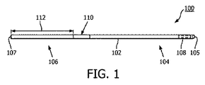
[0030] 次に、図1を参照するに、本開示の一実施形態による血管内デバイス100の略側面図が示される。血管内デバイス100は、遠位端105に隣接する遠位部104と、近位端107に隣接する近位部106とを有するフレキシブル細長部材102を含む。コンポーネント108が、遠位端105の近位で、フレキシブル細長部材102の遠位部104内に配置される。一般に、コンポーネント108は、1つ以上の電子的、光学的及び電気光学的コンポーネントを代表する。コンポーネント108は、圧力センサ、流量センサ、温度センサ、撮像要素、光ファイバ、超音波トランスデューサ、リフレクタ、ミラー、プリズム、アブレーション要素、RF電極、導体及び/又はこれらの組み合わせである。血管内デバイスの使用目的に基づいて、特定のタイプのコンポーネント又はコンポーネントの組み合わせを選択することができる。幾つかの例では、コンポーネント108は、遠位端105から10cm未満、5cm未満又は3cm未満のところに配置される。幾つかの例では、コンポーネント108は、フレキシブル細長部材102のハウジング内に配置される。ハウジングは、幾つかの例では、フレキシブル細長部材102に固定される別箇のコンポーネントである。他の例では、ハウジングは、フレキシブル細長部材102の一部として一体形成される。
[0030] Referring now to FIG. 1, a schematic side view of an
[0031] 血管内デバイス100は更に、デバイスの近位部106に隣接するコネクタ110を含む。コネクタ110は、距離112だけ、フレキシブル細長部材102の近位端107から離間されている。一般に、距離112は、フレキシブル細長部材102の全長の0%乃至50%である。フレキシブル細長部材102の全長は任意の長さであってよいが、幾つかの実施形態では、全長は、約1300mm乃至約4000mmであり、幾つかの特定の実施形態は、1400mm、1900mm及び3000mmの長さを有する。したがって、幾つかの例では、コネクタ110は、近位端107に配置される。別の例では、コネクタ110は、近位端107から離間される。例えば幾つかの例では、コネクタ110は、近位端107から、約0mm乃至約1400mm離間されている。幾つかの特定の実施形態では、コネクタ110は、0mm、300mm及び1400mmの距離だけ近位端から離間されている。
[0031] The
[0032] コネクタ110は、血管内デバイス100と別のデバイスとの通信を容易にする。より具体的に、幾つかの実施形態では、コネクタ110は、コンポーネント108によって取得されたデータのコンピュータデバイス又はプロセッサといった別のデバイスへの通信を容易にする。したがって、幾つかの実施形態では、コネクタ110は電気的コネクタである。このような例では、コネクタ110は、フレキシブル細長部材102の長さに沿って延在し、コンポーネント108に電気的に結合される1つ以上の導電体への電気的接続を提供する。幾つかの実施形態では、導電体は、フレキシブル細長部材102のコア内に埋め込まれる。他の実施形態では、コネクタ110は光学的コネクタである。このような例では、コネクタ110は、フレキシブル細長部材102の長さに沿って延在し、コンポーネント108に光学的に結合される1つ以上の光学通信路(例えば光ファイバケーブル)への光学的接続を提供する。同様に、幾つかの実施形態では、光ファイバは、フレキシブル細長部材102のコア内に埋め込まれる。更に、幾つかの実施形態では、コネクタ110は、コンポーネント108に結合される導電体及び光学通信路の両方に電気的接続及び光学的接続の両方を提供する。この点につき、コンポーネント108は、幾つかの例では、複数の要素から成っている。コネクタ110は、直接的又は間接的に別のデバイスへの物理的接続を提供する。幾つかの例では、コネクタ110は、血管内デバイス100と別のデバイスとのワイヤレス通信を容易にする。一般に、任意の現行のワイヤレスプロトコル又は将来開発されるワイヤレスプロトコルを使用してよい。更に別の例では、コネクタ110は、別のデバイスへの物理的接続及びワイヤレス接続の両方を容易にする。
[0032] The
[0033] 上記されたように、幾つかの例では、コネクタ110は、血管内デバイス100のコンポーネント108と外部デバイスとの接続を提供する。したがって、幾つかの実施形態では、1つ以上の導電体、1つ以上の光路及び/又はこれらの組み合わせが、コネクタ110とコンポーネント108との間でフレキシブル細長部材102の長さに沿って延在し、コネクタ110とコンポーネント108との通信を容易にする。幾つかの例では、図6a乃至図10に関して以下に説明され、また、2013年12月30日に出願された米国特許出願第14/143,304号に説明されるように、導電体及び/又は光路のうちの少なくとも1つが、コア部材を取り囲む1つ以上のポリマー層内に埋め込まれる。上記特許出願は、参照することによりその全体が本明細書に組み込まれる。更に、幾つかの例では、2015年2月2日に出願された米国特許出願第14/611,921号に説明されるように、導電体及び/又は光路のうちの少なくとも1つが、フレキシブル細長部材102のコア内に埋め込まれる。上記特許出願は、参照することによりその全体が本明細書に組み込まれる。一般に、任意の数の導電体、光路及び/又はこれらの組み合わせが、コア内に埋め込まれていてもいなくても、コネクタ110とコンポーネント108との間でフレキシブル細長部材102の長さに沿って延在する。幾つかの例では、1乃至10個の導電体及び/又は光路が、コネクタ110とコンポーネント108との間でフレキシブル細長部材102の長さに沿って延在する。フレキシブル細長部材102の長さに沿って延在する通信路の数並びに導電体及び光路の数は、コンポーネント108の所望機能と、当該機能を提供するためにコンポーネント108を画定する対応する要素とによって決定される。
[0033] As described above, in some examples, the
[0034] 次に、図2を参照するに、本開示の一実施形態による血管内デバイス100の遠位部104の略側面図が示される。図示されるように、遠位部104は、コンポーネント108を含むハウジング124の各側に近位フレキシブル要素120及び遠位フレキシブル要素122を含む。近位フレキシブル要素120及び遠位フレキシブル要素122は、スロット付きチューブ、コイル及び/又はコイルが埋め込まれたチューブを含む任意の適切なフレキシブル要素であってよい。図2の図示される実施形態では、近位フレキシブル要素120は、スロット付き管状部材であり、遠位フレキシブル要素122は、コイルである。近位フレキシブル要素120を画定するスロット付き管状部材は、複数のスロット121を含む。一般に、スロット121は、任意のサイズ、形状、向き及び/又は間隔を有してよい。スロット121の特定のサイズ、形状、向き及び/又は間隔は、管状部材120の長さに沿った所望の柔軟性及び/又は柔軟性の遷移を達成するように選択することができる。例えば幾つかの実施態様では、血管内デバイス100の柔軟性は、デバイスが末梢に伸びるにつれて増加する。したがって、スロット121のサイズ、形状、向き及び/又は間隔は、所望の柔軟性の変化を達成するために管状部材120の長さに沿って適切に変えられる。図2の図示される実施形態では、各スロット121は、管状部材の外周周りに延在する同様の細長形状を有する。更に、スロット121間の間隔は、図2の図示される実施形態における管状部材の長さに沿って一定である。しかし、当然ながら、スロット121は、本開示の範囲から逸脱することなく、(高さ、長さ、幅、深さ等を含む)任意のサイズ、(幾何学的、非幾何学的及びこれらの組み合わせを含む)任意の形状、(線形、垂直、斜め及びこれらの組み合わせを含む)任意の向き、及び/又は、(固定、可変、対称、非対称及び/又はこれらの組み合わせを含む)任意の間隔を有してよい。
[0034] Referring now to FIG. 2, a schematic side view of the
[0035] 次に、図3を参照するに、幾つかの実施態様では、1つ以上のコア部材が、フレキシブル要素120又はフレキシブル要素122の少なくとも一方の中に延在する。例えば図3に示されるように、コア部材126が近位フレキシブル要素120内に延在する。同様に、コア部材128が遠位フレキシブル要素122内に延在する。幾つかの実施態様では、コア部材126及び128は、一体コンポーネントである(即ち、コア部材126は、コア部材128を画定するようにハウジング124内に延在する)。幾つかの例では、コア部材128は、成形リボンに結合される。一般に、遠位フレキシブル要素122、コア部材126、128及び/又は成形リボンは、血管内デバイス100の遠位部104の所望の機械的性能及び/又は柔軟性をもたらすようなサイズにされ、成形され、及び/又は、特定の材料でできている。例えば遠位フレキシブル要素122、コア部材126、128及び/又は成形リボンは、ニッケルチタン、即ち、ニチノール、ニッケルチタンコバルト、ステンレス鋼及び/若しくは様々なステンレス鋼合金といった金属若しくは金属合金、並びに/又は、ポリイミド、ポリエチレン等といったポリマーから形成される。しかし、本開示に従って任意の材料の組み合わせを使用することができる。更に、幾つかの実施態様では、フレキシブル要素120及び/又はフレキシブル要素122の少なくとも1つは、その中を延在するコア部材又は成形リボンを有さない。例えば幾つかの実施態様では、フレキシブル要素120は、コア部材を必要とすることなく、血管内デバイス100の遠位部104の適切な構造的完全性を提供する。
[0035] Referring now to FIG. 3, in some embodiments, one or more core members extend into at least one of the
[0036] はんだボール130又は他の適切な要素が、遠位フレキシブル要素122の遠位端に固定されてよい。図示されるように、はんだボール130は、血管構造といった患者の血管の中を進むのに適した非外傷性先端を有する血管内デバイス100の遠位端105を画定する。幾つかの実施形態では、はんだボール130ではなく、流量センサが遠位端105に配置される。
[0036] A
[0037] 血管内デバイス100の遠位部104(だけでなく、近位部106及びフレキシブル細長部材102)は、本開示に従って、近位部106がソリッドコアを含み、遠位フレキシブル要素122がスロット付き管状部材を含む限り、任意の適切なアプローチを使用して形成されてよい。したがって、幾つかの実施態様では、血管内デバイス100は、米国特許第5,125,137号、米国特許第5,873,835号、米国特許第6,106,476号、米国特許第6,551,250号、2013年6月28日に出願された米国特許出願第13/931,052号、2013年12月19日に出願された米国特許出願第14/135,117号、2013年12月20日に出願された米国特許出願第14/137,364号、2013年12月23日に出願された米国特許出願第14/139,543号、2013年12月30日に出願された米国特許出願第14/143,304号、及び、2015年2月2日に出願された米国特許出願第14/611,921号のうちの1つ以上に説明される遠位セクション、中間セクション及び/又は近位セクションと同様の特徴を含む。これらのそれぞれは、参照することによりその全体が本明細書に組み込まれる。
[0037] The distal portion 104 (as well as the
[0038] 次に、図4を参照するに、本開示の別の実施形態による血管内デバイス100の遠位部104の略側面図が示される。具体的に、図4の実施形態は、コンポーネント108用の別個のハウジングを含まない。代わりに、コンポーネント108は、近位フレキシブル要素120内に取り付けられる。コンポーネント108は、適切な機械式留め具/結合器、接着剤及び/又はこれらの組み合わせを使用して、近位フレキシブル要素120内に固定される。幾つかの例では、管状部材120のスロット121は、コンポーネント108の周辺環境への流体アクセスを提供する。例えば幾つかの実施態様では、コンポーネント108に隣接するスロット121は、コンポーネント108による圧力及び/又は流量測定を容易にするようなサイズにされ、形にされ、向きにされ及び/又は離間される。幾つかの例では、コンポーネント108用のハウジングを除外することによって、遠位部104内の血管内デバイス100の柔軟性及び/又は柔軟性の一貫性を向上させ、これは、血管内デバイス100のハンドリングを向上させる。
[0038] Referring now to FIG. 4, a schematic side view of the
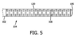
[0039] 次に、図5を参照するに、本開示の別の実施形態による血管内デバイス100の遠位部104の略側面図が示される。具体的に、図5の実施形態は、コンポーネント108用の別個のハウジング又は別箇の遠位フレキシブル要素122を含まない。代わりに、コンポーネント108は、血管内デバイス100の遠位端105まで延在する近位フレキシブル要素120内に取り付けられる。コンポーネント108は、適切な機械式留め具/結合器、接着剤及び/又はこれらの組み合わせを使用して、近位フレキシブル要素120内に固定される。幾つかの例では、管状部材120のスロット121は、コンポーネント108の周辺環境への流体アクセスを提供する。例えば幾つかの実施態様では、コンポーネント108に隣接するスロット121は、コンポーネント108による圧力及び/又は流量測定を容易にするようなサイズにされ、形にされ、向きにされ及び/又は離間される。更に、幾つかの例では、管状部材120のスロット121は、遠位端105に隣接して柔軟性を増加させるように、血管内デバイスの長さに沿って変化する。具体的に、遠位端105に隣接するスロット121は、先端コイルまで同様の柔軟性を提供するようなサイズにされ、形にされ、向きにされ及び/又は離間されるが、単一のコンポーネントを使用する。図示される実施形態では、遠位端105に隣接するスロット121は、より近くに配置される(例えばコンポーネント108の近位)スロット121に比べて間隔が小さい。幾つかの例では、コンポーネント108用のハウジング及び/又は別箇の遠位フレキシブル要素122を除外することによって、複数の個別のコンポーネントを共に結合する必要がないため、デバイスの製造可能性を向上させる。これは更に、製造又は使用中にデバイスが故障する潜在的な領域も除外する。例えば血管内デバイスの遠位部104に沿って単一の一体型フレキシブル要素を使用することによって、血管内デバイス100の柔軟性及び/又は柔軟性の一貫性が、スロット121のサイズ、形状、向き及び/又は間隔を選択することによって正確に制御され、これにより、所望の柔軟性及び/又はハンドリングプロファイルが達成される。
[0039] Referring now to FIG. 5, a schematic side view of the
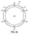
[0040] 次に、図6a及び図6bを参照するに、本開示の一実施形態による血管内デバイス100の近位部106の態様が示される。具体的に、図6aは、本開示の一実施形態による近位部106の略側面図であり、図6bは、本開示の一実施形態による近位部106の端部断面図である。図示されるように、近位部106のフレキシブル細長部材102は、導体138が含浸された外層136によって取り囲まれるコア部材134を含む。コア部材134は、ステンレス鋼、ニッケル及びチタン合金(ニチノール)、ポリエーテルエーテルケトン、熱により真っすぐに伸ばされた304ステンレス鋼又は他の金属若しくはポリマー材料といった適切な材料で作られる。外層136は、適切なポリマー材料で作られる。外層136は、ワイヤコーティング技術を使用して、コア部材134上にコーティングされてよい。コーティングが厚くなるにつれて、導体138が外層136によってコーティングされ外層136内に埋め込まれるように、コーティング処理に導入される。外層136は、ポリマー材料を使用してよいが、幾つかの例では、ポリイミドを含む。導体138は、対称パターン及び非対称パターンを含む任意の適切なやり方でコア部材134の外周の周りに離間されてよい。特定の実施形態では、導体138は、図6b及び図7に示されるように、コア部材134の外周の周りに実質的に等しく離間される。
[0040] Referring now to FIGS. 6a and 6b, aspects of the
[0041] 上記されたように、一般に、任意の数の導体を使用することができる。例えば電気的な固体センサ(例えば圧力、温度、流量等)を有する幾つかの実施態様では、センサに接続するために2つの導体が使用される。圧電抵抗センサ(例えば圧力センサ)を使用する他の実施態様では、3つの導体が使用される。撮像用の超音波センサを使用する更に別の実施態様では、4つの導体が使用される(例えば「CIRCUIT ARCHITECTURES AND ELECTRICAL INTERFACES FOR ROTATIONAL INTRAVASCULAR ULTRASOUND (IVUS) DEVICES」なる名称の米国特許第8,864,674号及び/又は「INTRACASCULAR ULTRASOUND IMAGING APPARATUS, INTERFACE ARCHITECTURE, AND METHOD OF MANUFACTURING」なる名称の米国特許出願公開第2014/0187960号に説明される。これらはそれぞれ、参照することによりその全体が本明細書に組み込まれる)。図6bは、3つの導体を使用する実施形態を示し、図6cは、6つの導体138を使用する実施形態を示す。更に、コア134も、幾つかの実施形態では、導体として使用される。使用される導体138の数は、使用される検知コンポーネントの数及び/又はタイプに基づいて選択される。
[0041] As noted above, in general, any number of conductors can be used. In some embodiments having, for example, an electrical solid state sensor (eg, pressure, temperature, flow rate, etc.), two conductors are used to connect to the sensor. In other embodiments using piezoresistive sensors (eg pressure sensors), three conductors are used. In yet another embodiment using an imaging ultrasonic sensor, four conductors are used (eg, US Pat. No. 8,864, entitled “CIRCUIT ARCHITECTURES AND ELECTRICAL INTERFACES FOR ROTATIONAL INTRAVASCULAR ULTRASOUND (IVUS) DEVICES”). No. 674 and / or US Patent Application Publication No. 2014/0187960 entitled “INTRACASCULAR ULTRASOUND IMAGING APPARATUS, INTERFACE ARCHITECTURE, AND METHOD OF MANUFACTURING”, each of which is hereby incorporated by reference in its entirety. Incorporated into). FIG. 6 b shows an embodiment using three conductors, and FIG. 6 c shows an embodiment using six
[0042] 特定の実施形態では、外層136の所望の外径に達した後、最終コーティングが、近位部106及び血管内デバイス100に塗布される。親水性及び疎水性コーティングを含む潤滑性を提供する任意の適切な材料が使用されてよい。例示的なコーティング材料には、PTFE含浸ポリイミド、シリコーンベースのコーティング、親水性コーティング及び疎水性コーティングが含まれる。
[0042] In certain embodiments, after reaching the desired outer diameter of the
[0043] 次に、図7を参照するに、本開示の一実施形態による外層136内に埋め込まれた導体138の露出部を示す血管内デバイス100の近位部106の略側面図が示される。図示されるように、外層136の1つ以上のセクションが変更されて、埋め込まれた導体138の対応するセクションが露出される。化学エッチング、機械的カッティング及びせん断、レーザアブレーション並びに/又はこれらの組み合わせを含む任意の適切な技術を使用して、導体138のセクションが露出される。特定の実施形態では、レーザアブレーションを使用して外層136の特定のセクション(例えば特定のサイズ、形状、深さ等を有する)が切り取られて、埋め込まれた導体138が露出される。幾つかの例では、円周アブレーションを使用してもよい。ポリマー材料のレーザアブレーションは、当技術分野において知られており、Kumagai(Applied Physics Letters、65(14):1850−1852、2004)、Sutcliffe(Journal of Applied Physics、60(9):3315−3322、1986)及びBlanchet他(Science、262(5134):719−721、1993)に説明されるような既知の技術によって達成することができる。これらのそれぞれは、参照することによりその全体が本明細書に組み込まれる。
[0043] Referring now to FIG. 7, shown is a schematic side view of the
[0044] 幾つかの例では、フレキシブル細長部材102の近位端及び/又は遠位端において基準リングが取り除かれ、デバイスの外周に対して外層136のどこに導体138が存在するかを特定する。導電性ワイヤの遠位端は、直接又は間接的にコンポーネント108に結合するために、特定の研削形状に研磨されてよい。例えば導体138は、はんだ付け溶接、1つ以上の追加の導電性部材、リード線及び/又は他の既知の技術を使用して、コンポーネント108に結合される。幾つかの例では、外層136のセクションが取り除かれて、追加の導体を介してコンポーネント108に結合される導体138の遠位部が露出される。幾つかの例では、フレキシブル細長部材102の遠位端は、図2乃至図5に関して上記されたのと同様に遠位部に結合される。このような例では、導体138は、コンポーネント108まで近位フレキシブル要素120に沿って及び/又はその中を延在する導体に結合される。更に、フレキシブル細長部材102は、機械的結合器、接着剤、はんだ、溶接及び/又はこれらの組み合わせを使用して、直接又は間接的に近位フレキシブル要素に結合されてよい。幾つかの例では、フレキシブル細長部材102は、米国特許第5,125,137号、米国特許第5,873,835号、米国特許第6,106,476号、米国特許第6,551,250号、2013年6月28日に出願された米国特許出願第13/931,052号、2013年12月19日に出願された米国特許出願第14/135,117号、2013年12月20日に出願された米国特許出願第14/137,364号、2013年12月23日に出願された米国特許出願第14/139,543号、2013年12月30日に出願された米国特許出願第14/143,304号、及び、2015年2月2日に出願された米国特許出願第14/611,921号のうちの1つ以上に説明されるセクションと同様の遠位セクション、中間セクション及び/又は近位セクションに結合される。これらのそれぞれは、参照することによりその全体が本明細書に組み込まれる。
[0044] In some examples, the reference ring is removed at the proximal and / or distal ends of the flexible
[0045] 次に、図8を参照するに、本開示の一実施形態による図7の埋め込み導体の露出部上に形成される導電性バンド140を示す血管内デバイス100の近位部106の略側面図が示される。図示されるように、導電性材料が、導体138の露出セクション上でフレキシブル細長部材102に付与される。導電性材料は、導体138の露出セクションを覆い、露出導体138に接触する導電性バンド140を画定する。通常、各導電性バンド140は、当該導電性バンド140が導体138の外部電気コネクタとして機能を果たすように、単一の導体138に(導体の長さに沿って1つ以上の場所において)接続される。しかし、幾つかの実施態様では、導電性バンド140は、2つ以上の導体138に接続される。導電性材料は、一般に、金といった金属である。一般に、任意の適切な技術を使用して、導電性材料を露出導体に付与することができる。特定の実施形態では、導電性材料は、導電性ワイヤの露出セクション上にプリントされ、焼結される。金属のプリンティング及び焼結は知られている。例えばKydd(米国特許第5,882,722号及び第6,036,889号)、Karapatis他(Rapid Prototyping Journal、4(2):77−89、1998)及びKruth他(Assembly Automation、23(4):357−371、2003)を参照されたい。これらのそれぞれの内容は、参照することによりその全体が本明細書に組み込まれる。
[0045] Referring now to FIG. 8, the
[0046] 任意の所望のパターンの導電性材料が、フレキシブル細長部材102上に配置されて、導電性バンド140が画定される。例えば導電性バンドは、固体、複数のリング、らせん状構造体又は最適な機能を提供する任意の他のパターンである。したがって、図9は、2つの例示的な導電性バンドの構成を示す。具体的に、図面の左側の構成は、複数の導電性バンド140を示し、それぞれ、共通の導体138に接続されてコネクタ142が画定される。右側の構成は、フレキシブル細長部材の別の導体138用のコネクタ144を画定する固体の導電性バンド140を示す。コネクタ142及び144は、図1に関して上記されたコネクタ110の一部であってよい。
[0046] Any desired pattern of conductive material is disposed on the flexible
[0047] 本開示のガイドワイヤは、センサによって受信された信号を圧力及び速度測定値に変換するコンピュータデバイス(例えばラップトップコンピュータ、デスクトップコンピュータ又はタブレットコンピュータ)又は生理モニタといった器具に接続される。器具は更に、冠血流予備比(CFR)及び血流予備量比(FFR)を計算し、測定値及び計算を、ユーザインターフェースを介してユーザに提供する。幾つかの実施形態では、ユーザは、視覚インターフェースとインタラクトして、本開示の血管内デバイスによって取得されたデータに関連する画像を確認する。ユーザからの入力(例えばパラメータ又は選択)は、電子デバイス内のプロセッサによって受信される。選択は、可視ディスプレイで表示される。 [0047] The guidewire of the present disclosure is connected to an instrument such as a computing device (eg, a laptop computer, desktop computer or tablet computer) or a physiological monitor that converts the signals received by the sensor into pressure and velocity measurements. The instrument further calculates a coronary flow reserve ratio (CFR) and a reserve blood flow ratio (FFR) and provides measurements and calculations to the user via the user interface. In some embodiments, the user interacts with the visual interface to see images associated with data acquired by the disclosed intravascular device. Input from the user (eg, parameter or selection) is received by a processor in the electronic device. The selection is displayed on a visual display.
[0048] 当業者であれば、上記装置、システム及び方法は、様々な方法で修正可能であることは認識するであろう。したがって、当業者であれば、本開示によって包含される実施形態は、上記特定の例示的な実施形態に限定されないことを理解するであろう。この点につき、例示的な実施形態が図示され、説明されたが、様々な修正、変更及び置換が上記開示において考えられる。例えば様々な実施形態の特徴は、異なる実施形態の特徴と組み合わせることができる。1つ以上のステップを、本明細書において説明される方法に追加しても、そこから取り除いてもよい。当業者であれば、方法のステップは、本明細書において説明される順番とは異なる順番で行われてもよいことを理解するであろう。当然ながら、このような変更は、本開示の範囲から逸脱することなく上記のものに行われてよい。したがって、添付の請求項が広義に且つ本開示と一貫して解釈されることが適切である。 [0048] Those skilled in the art will recognize that the above devices, systems and methods may be modified in various ways. Thus, those skilled in the art will appreciate that the embodiments encompassed by the present disclosure are not limited to the specific exemplary embodiments described above. In this regard, although exemplary embodiments have been illustrated and described, various modifications, changes and substitutions are contemplated in the above disclosure. For example, features of various embodiments can be combined with features of different embodiments. One or more steps may be added to or removed from the methods described herein. One skilled in the art will appreciate that the method steps may be performed in a different order than the order described herein. Of course, such changes may be made to the above without departing from the scope of the present disclosure. Accordingly, it is appropriate that the appended claims be construed broadly and consistently with the present disclosure.
Claims (20)
前記近位部に結合され、スロット付き管状部材、及び、前記近位部の前記複数の導体に電気的に結合される検知要素を有する遠位部と、
を含む、検知ガイドワイヤ。 A proximal portion having a solid core member and a plurality of conductors embedded in an outer layer surrounding the solid core member;
A distal section having a slotted tubular member coupled to the proximal section and a sensing element electrically coupled to the plurality of conductors of the proximal section;
Including a sensing guidewire.
ソリッドコア部材、及び、前記ソリッドコア部材を取り囲む外層内に埋め込まれる複数の導体を有する近位部を得るステップと、
遠位部のスロット付き管状部材が、前記近位部から遠位に延在し、前記遠位部の検知要素が、前記近位部の前記複数の導体に電気的に結合されるように、前記遠位部を前記近位部に結合するステップと、
を含む、方法。 A method of assembling a detection guide wire,
Obtaining a proximal portion having a solid core member and a plurality of conductors embedded in an outer layer surrounding the solid core member;
A distal slotted tubular member extends distally from the proximal portion such that the distal sensing element is electrically coupled to the plurality of conductors of the proximal portion; Coupling the distal portion to the proximal portion;
Including a method.
Applications Claiming Priority (3)
| Application Number | Priority Date | Filing Date | Title |
|---|---|---|---|
| US201562187021P | 2015-06-30 | 2015-06-30 | |
| US62/187,021 | 2015-06-30 | ||
| PCT/EP2016/065291 WO2017001552A1 (en) | 2015-06-30 | 2016-06-30 | Intravascular devices, systems, and methods with a solid core proximal section and a slotted, tubular distal section |
Publications (2)
| Publication Number | Publication Date |
|---|---|
| JP2018527967A true JP2018527967A (en) | 2018-09-27 |
| JP2018527967A5 JP2018527967A5 (en) | 2019-08-08 |
Family
ID=56497714
Family Applications (1)
| Application Number | Title | Priority Date | Filing Date |
|---|---|---|---|
| JP2017567414A Ceased JP2018527967A (en) | 2015-06-30 | 2016-06-30 | Intravascular device, system and method having a solid core proximal section and a slotted tubular distal section |
Country Status (5)
| Country | Link |
|---|---|
| US (1) | US20180184981A1 (en) |
| EP (1) | EP3316763A1 (en) |
| JP (1) | JP2018527967A (en) |
| CN (1) | CN107847137A (en) |
| WO (1) | WO2017001552A1 (en) |
Families Citing this family (3)
| Publication number | Priority date | Publication date | Assignee | Title |
|---|---|---|---|---|
| US9624095B2 (en) * | 2012-12-28 | 2017-04-18 | Volcano Corporation | Capacitive intravascular pressure-sensing devices and associated systems and methods |
| US11173285B2 (en) * | 2018-06-28 | 2021-11-16 | Biosense Webster (Israel) Ltd. | Producing a guidewire comprising a position sensor |
| CN113827210A (en) * | 2021-11-26 | 2021-12-24 | 微创神通医疗科技(上海)有限公司 | Guide wire, signal receiving device and intravascular pressure measuring structure |
Citations (5)
| Publication number | Priority date | Publication date | Assignee | Title |
|---|---|---|---|---|
| US20140081244A1 (en) * | 2012-09-17 | 2014-03-20 | Boston Scientific Scimed, Inc. | Pressure sensing guidewire |
| JP2014507197A (en) * | 2010-12-29 | 2014-03-27 | セント・ジュード・メディカル・エイトリアル・フィブリレーション・ディヴィジョン・インコーポレーテッド | Medical device guidewire with position sensor |
| US20140187874A1 (en) * | 2012-12-31 | 2014-07-03 | Volcano Corporation | Intravascular Devices, Systems, and Methods |
| WO2015059578A2 (en) * | 2013-10-25 | 2015-04-30 | St. Jude Medical Systems Ab | Sensor guide wire device and system including a sensor guide wire device |
| US20150148693A1 (en) * | 2013-11-22 | 2015-05-28 | Volcano Corporation | Sensor Mounting Assembly for Sensored Guidewire and Associated Devices, Systems, and Methods |
Family Cites Families (10)
| Publication number | Priority date | Publication date | Assignee | Title |
|---|---|---|---|---|
| US5125137A (en) | 1990-09-06 | 1992-06-30 | Cardiometrics, Inc. | Method for providing a miniature ultrasound high efficiency transducer assembly |
| US5873835A (en) | 1993-04-29 | 1999-02-23 | Scimed Life Systems, Inc. | Intravascular pressure and flow sensor |
| WO1996007351A1 (en) | 1994-09-02 | 1996-03-14 | Cardiometrics, Inc. | Ultra miniature pressure sensor and guidewire using the same and method |
| US5882722A (en) | 1995-07-12 | 1999-03-16 | Partnerships Limited, Inc. | Electrical conductors formed from mixtures of metal powders and metallo-organic decompositions compounds |
| US6551250B2 (en) | 2001-03-29 | 2003-04-22 | Hassan Khalil | Transit time thermodilution guidewire system for measuring coronary flow velocity |
| US20090177119A1 (en) * | 2008-01-03 | 2009-07-09 | Boston Scientific Scimed, Inc. | Articulating intracorporeal medical device |
| US10226185B2 (en) * | 2012-05-03 | 2019-03-12 | St. Jude Medical Coordination Center Bvba | Tube and sensor guide wire comprising tube |
| US8864674B2 (en) | 2012-05-11 | 2014-10-21 | Volcano Corporation | Circuit architectures and electrical interfaces for rotational intravascular ultrasound (IVUS) devices |
| WO2014105725A1 (en) | 2012-12-28 | 2014-07-03 | Volcano Corporation | Intravascular ultrasound imaging apparatus, interface architecture, and method of manufacturing |
| US9795307B2 (en) * | 2014-12-05 | 2017-10-24 | Boston Scientific Scimed, Inc. | Pressure sensing guidewires |
-
2016
- 2016-06-30 US US15/741,263 patent/US20180184981A1/en not_active Abandoned
- 2016-06-30 CN CN201680038185.2A patent/CN107847137A/en active Pending
- 2016-06-30 JP JP2017567414A patent/JP2018527967A/en not_active Ceased
- 2016-06-30 EP EP16741245.1A patent/EP3316763A1/en not_active Withdrawn
- 2016-06-30 WO PCT/EP2016/065291 patent/WO2017001552A1/en active Application Filing
Patent Citations (5)
| Publication number | Priority date | Publication date | Assignee | Title |
|---|---|---|---|---|
| JP2014507197A (en) * | 2010-12-29 | 2014-03-27 | セント・ジュード・メディカル・エイトリアル・フィブリレーション・ディヴィジョン・インコーポレーテッド | Medical device guidewire with position sensor |
| US20140081244A1 (en) * | 2012-09-17 | 2014-03-20 | Boston Scientific Scimed, Inc. | Pressure sensing guidewire |
| US20140187874A1 (en) * | 2012-12-31 | 2014-07-03 | Volcano Corporation | Intravascular Devices, Systems, and Methods |
| WO2015059578A2 (en) * | 2013-10-25 | 2015-04-30 | St. Jude Medical Systems Ab | Sensor guide wire device and system including a sensor guide wire device |
| US20150148693A1 (en) * | 2013-11-22 | 2015-05-28 | Volcano Corporation | Sensor Mounting Assembly for Sensored Guidewire and Associated Devices, Systems, and Methods |
Also Published As
| Publication number | Publication date |
|---|---|
| CN107847137A (en) | 2018-03-27 |
| US20180184981A1 (en) | 2018-07-05 |
| WO2017001552A1 (en) | 2017-01-05 |
| EP3316763A1 (en) | 2018-05-09 |
Similar Documents
| Publication | Publication Date | Title |
|---|---|---|
| US11324410B2 (en) | Intravascular devices, systems, and methods having a core wire with embedded conductors | |
| EP3122240B1 (en) | Intravascular devices, systems, and methods having a core wire formed of multiple materials | |
| US20240008755A1 (en) | Mounting structures for components of intravascular devices | |
| US10927003B2 (en) | Capacitive intravascular pressure-sensing devices and associated systems and methods | |
| US11864918B2 (en) | Intravascular devices, systems, and methods having separate sections with engaged core components | |
| US10350389B2 (en) | Intravascular devices, systems, and methods having a radiopaque patterned flexible tip | |
| JP2018527967A (en) | Intravascular device, system and method having a solid core proximal section and a slotted tubular distal section |
Legal Events
| Date | Code | Title | Description |
|---|---|---|---|
| A521 | Request for written amendment filed |
Free format text: JAPANESE INTERMEDIATE CODE: A523 Effective date: 20190628 |
|
| A621 | Written request for application examination |
Free format text: JAPANESE INTERMEDIATE CODE: A621 Effective date: 20190628 |
|
| A977 | Report on retrieval |
Free format text: JAPANESE INTERMEDIATE CODE: A971007 Effective date: 20200605 |
|
| A131 | Notification of reasons for refusal |
Free format text: JAPANESE INTERMEDIATE CODE: A131 Effective date: 20200622 |
|
| A601 | Written request for extension of time |
Free format text: JAPANESE INTERMEDIATE CODE: A601 Effective date: 20200918 |
|
| A521 | Request for written amendment filed |
Free format text: JAPANESE INTERMEDIATE CODE: A523 Effective date: 20201221 |
|
| A01 | Written decision to grant a patent or to grant a registration (utility model) |
Free format text: JAPANESE INTERMEDIATE CODE: A01 Effective date: 20210308 |
|
| A045 | Written measure of dismissal of application [lapsed due to lack of payment] |
Free format text: JAPANESE INTERMEDIATE CODE: A045 Effective date: 20210727 |