EP3122240B1 - Intravascular devices, systems, and methods having a core wire formed of multiple materials - Google Patents
Intravascular devices, systems, and methods having a core wire formed of multiple materials Download PDFInfo
- Publication number
- EP3122240B1 EP3122240B1 EP15768252.7A EP15768252A EP3122240B1 EP 3122240 B1 EP3122240 B1 EP 3122240B1 EP 15768252 A EP15768252 A EP 15768252A EP 3122240 B1 EP3122240 B1 EP 3122240B1
- Authority
- EP
- European Patent Office
- Prior art keywords
- core member
- guide wire
- section
- distal portion
- conductors
- Prior art date
- Legal status (The legal status is an assumption and is not a legal conclusion. Google has not performed a legal analysis and makes no representation as to the accuracy of the status listed.)
- Active
Links
- 239000000463 material Substances 0.000 title claims description 45
- 238000000034 method Methods 0.000 title claims description 27
- 239000004020 conductor Substances 0.000 claims description 71
- 238000004891 communication Methods 0.000 claims description 15
- 229910052751 metal Inorganic materials 0.000 claims description 15
- 239000002184 metal Substances 0.000 claims description 15
- 230000008878 coupling Effects 0.000 claims description 12
- 238000010168 coupling process Methods 0.000 claims description 12
- 238000005859 coupling reaction Methods 0.000 claims description 12
- 229920000642 polymer Polymers 0.000 claims description 10
- 229910001000 nickel titanium Inorganic materials 0.000 claims description 9
- HLXZNVUGXRDIFK-UHFFFAOYSA-N nickel titanium Chemical compound [Ti].[Ti].[Ti].[Ti].[Ti].[Ti].[Ti].[Ti].[Ti].[Ti].[Ti].[Ni].[Ni].[Ni].[Ni].[Ni].[Ni].[Ni].[Ni].[Ni].[Ni].[Ni].[Ni].[Ni].[Ni] HLXZNVUGXRDIFK-UHFFFAOYSA-N 0.000 claims description 8
- 239000010935 stainless steel Substances 0.000 claims description 7
- 229910001220 stainless steel Inorganic materials 0.000 claims description 6
- 150000002739 metals Chemical class 0.000 claims description 5
- 229910045601 alloy Inorganic materials 0.000 claims description 3
- 239000000956 alloy Substances 0.000 claims description 3
- 238000007493 shaping process Methods 0.000 claims description 3
- 239000011162 core material Substances 0.000 description 53
- 230000003287 optical effect Effects 0.000 description 18
- 238000000576 coating method Methods 0.000 description 14
- 239000011248 coating agent Substances 0.000 description 11
- 208000031481 Pathologic Constriction Diseases 0.000 description 10
- 230000036262 stenosis Effects 0.000 description 10
- 208000037804 stenosis Diseases 0.000 description 10
- 210000004204 blood vessel Anatomy 0.000 description 8
- 238000003384 imaging method Methods 0.000 description 8
- 230000037361 pathway Effects 0.000 description 7
- 238000002604 ultrasonography Methods 0.000 description 7
- 230000008867 communication pathway Effects 0.000 description 5
- 238000013461 design Methods 0.000 description 5
- 229910000679 solder Inorganic materials 0.000 description 5
- 230000015572 biosynthetic process Effects 0.000 description 4
- 239000013078 crystal Substances 0.000 description 4
- 239000011810 insulating material Substances 0.000 description 4
- 238000005259 measurement Methods 0.000 description 4
- -1 MP35N Inorganic materials 0.000 description 3
- 239000004642 Polyimide Substances 0.000 description 3
- 230000017531 blood circulation Effects 0.000 description 3
- 238000005530 etching Methods 0.000 description 3
- 239000012212 insulator Substances 0.000 description 3
- 238000002608 intravascular ultrasound Methods 0.000 description 3
- 238000012014 optical coherence tomography Methods 0.000 description 3
- 229920001721 polyimide Polymers 0.000 description 3
- 230000008569 process Effects 0.000 description 3
- 210000005166 vasculature Anatomy 0.000 description 3
- PXHVJJICTQNCMI-UHFFFAOYSA-N Nickel Chemical compound [Ni] PXHVJJICTQNCMI-UHFFFAOYSA-N 0.000 description 2
- 238000002679 ablation Methods 0.000 description 2
- OIRDTQYFTABQOQ-KQYNXXCUSA-N adenosine Chemical compound C1=NC=2C(N)=NC=NC=2N1[C@@H]1O[C@H](CO)[C@@H](O)[C@H]1O OIRDTQYFTABQOQ-KQYNXXCUSA-N 0.000 description 2
- 238000009530 blood pressure measurement Methods 0.000 description 2
- 238000000227 grinding Methods 0.000 description 2
- 208000019622 heart disease Diseases 0.000 description 2
- 230000000544 hyperemic effect Effects 0.000 description 2
- 230000004048 modification Effects 0.000 description 2
- 238000012986 modification Methods 0.000 description 2
- 239000013307 optical fiber Substances 0.000 description 2
- BASFCYQUMIYNBI-UHFFFAOYSA-N platinum Chemical compound [Pt] BASFCYQUMIYNBI-UHFFFAOYSA-N 0.000 description 2
- 239000007787 solid Substances 0.000 description 2
- 230000002792 vascular Effects 0.000 description 2
- 239000002126 C01EB10 - Adenosine Substances 0.000 description 1
- RYGMFSIKBFXOCR-UHFFFAOYSA-N Copper Chemical compound [Cu] RYGMFSIKBFXOCR-UHFFFAOYSA-N 0.000 description 1
- 229910000990 Ni alloy Inorganic materials 0.000 description 1
- 239000004696 Poly ether ether ketone Substances 0.000 description 1
- BQCADISMDOOEFD-UHFFFAOYSA-N Silver Chemical compound [Ag] BQCADISMDOOEFD-UHFFFAOYSA-N 0.000 description 1
- 229910001069 Ti alloy Inorganic materials 0.000 description 1
- 238000009825 accumulation Methods 0.000 description 1
- 229960005305 adenosine Drugs 0.000 description 1
- 239000000853 adhesive Substances 0.000 description 1
- 230000001070 adhesive effect Effects 0.000 description 1
- 230000004075 alteration Effects 0.000 description 1
- 210000003484 anatomy Anatomy 0.000 description 1
- 238000002583 angiography Methods 0.000 description 1
- 238000002399 angioplasty Methods 0.000 description 1
- 210000001367 artery Anatomy 0.000 description 1
- 238000005452 bending Methods 0.000 description 1
- 230000008901 benefit Effects 0.000 description 1
- 210000004556 brain Anatomy 0.000 description 1
- 230000008859 change Effects 0.000 description 1
- 238000002591 computed tomography Methods 0.000 description 1
- 238000007796 conventional method Methods 0.000 description 1
- 229910052802 copper Inorganic materials 0.000 description 1
- 239000010949 copper Substances 0.000 description 1
- 230000001419 dependent effect Effects 0.000 description 1
- 230000001627 detrimental effect Effects 0.000 description 1
- 229940079593 drug Drugs 0.000 description 1
- 239000003814 drug Substances 0.000 description 1
- 238000002592 echocardiography Methods 0.000 description 1
- 210000003414 extremity Anatomy 0.000 description 1
- 239000000835 fiber Substances 0.000 description 1
- 230000006870 function Effects 0.000 description 1
- PCHJSUWPFVWCPO-UHFFFAOYSA-N gold Chemical compound [Au] PCHJSUWPFVWCPO-UHFFFAOYSA-N 0.000 description 1
- 229910052737 gold Inorganic materials 0.000 description 1
- 239000010931 gold Substances 0.000 description 1
- 230000002209 hydrophobic effect Effects 0.000 description 1
- 238000009413 insulation Methods 0.000 description 1
- 208000028867 ischemia Diseases 0.000 description 1
- 230000000302 ischemic effect Effects 0.000 description 1
- 238000000608 laser ablation Methods 0.000 description 1
- 230000003902 lesion Effects 0.000 description 1
- 238000004519 manufacturing process Methods 0.000 description 1
- 230000007246 mechanism Effects 0.000 description 1
- 230000035479 physiological effects, processes and functions Effects 0.000 description 1
- 238000007747 plating Methods 0.000 description 1
- 229910052697 platinum Inorganic materials 0.000 description 1
- 229920002530 polyetherether ketone Polymers 0.000 description 1
- 229920001296 polysiloxane Polymers 0.000 description 1
- 239000004810 polytetrafluoroethylene Substances 0.000 description 1
- 229920001343 polytetrafluoroethylene Polymers 0.000 description 1
- 238000007639 printing Methods 0.000 description 1
- 238000012545 processing Methods 0.000 description 1
- 230000001737 promoting effect Effects 0.000 description 1
- 230000003014 reinforcing effect Effects 0.000 description 1
- 210000002254 renal artery Anatomy 0.000 description 1
- 208000037803 restenosis Diseases 0.000 description 1
- 239000004065 semiconductor Substances 0.000 description 1
- 229910052709 silver Inorganic materials 0.000 description 1
- 239000004332 silver Substances 0.000 description 1
- 229910001256 stainless steel alloy Inorganic materials 0.000 description 1
- 238000006467 substitution reaction Methods 0.000 description 1
- 230000003319 supportive effect Effects 0.000 description 1
- 238000001356 surgical procedure Methods 0.000 description 1
- 238000012360 testing method Methods 0.000 description 1
- 230000007704 transition Effects 0.000 description 1
- 210000003462 vein Anatomy 0.000 description 1
- 230000000007 visual effect Effects 0.000 description 1
Images

Classifications
-
- A—HUMAN NECESSITIES
- A61—MEDICAL OR VETERINARY SCIENCE; HYGIENE
- A61M—DEVICES FOR INTRODUCING MEDIA INTO, OR ONTO, THE BODY; DEVICES FOR TRANSDUCING BODY MEDIA OR FOR TAKING MEDIA FROM THE BODY; DEVICES FOR PRODUCING OR ENDING SLEEP OR STUPOR
- A61M25/00—Catheters; Hollow probes
- A61M25/01—Introducing, guiding, advancing, emplacing or holding catheters
- A61M25/09—Guide wires
-
- A—HUMAN NECESSITIES
- A61—MEDICAL OR VETERINARY SCIENCE; HYGIENE
- A61B—DIAGNOSIS; SURGERY; IDENTIFICATION
- A61B5/00—Measuring for diagnostic purposes; Identification of persons
- A61B5/02—Detecting, measuring or recording pulse, heart rate, blood pressure or blood flow; Combined pulse/heart-rate/blood pressure determination; Evaluating a cardiovascular condition not otherwise provided for, e.g. using combinations of techniques provided for in this group with electrocardiography or electroauscultation; Heart catheters for measuring blood pressure
- A61B5/021—Measuring pressure in heart or blood vessels
- A61B5/0215—Measuring pressure in heart or blood vessels by means inserted into the body
-
- A—HUMAN NECESSITIES
- A61—MEDICAL OR VETERINARY SCIENCE; HYGIENE
- A61B—DIAGNOSIS; SURGERY; IDENTIFICATION
- A61B5/00—Measuring for diagnostic purposes; Identification of persons
- A61B5/02—Detecting, measuring or recording pulse, heart rate, blood pressure or blood flow; Combined pulse/heart-rate/blood pressure determination; Evaluating a cardiovascular condition not otherwise provided for, e.g. using combinations of techniques provided for in this group with electrocardiography or electroauscultation; Heart catheters for measuring blood pressure
- A61B5/026—Measuring blood flow
-
- A—HUMAN NECESSITIES
- A61—MEDICAL OR VETERINARY SCIENCE; HYGIENE
- A61L—METHODS OR APPARATUS FOR STERILISING MATERIALS OR OBJECTS IN GENERAL; DISINFECTION, STERILISATION OR DEODORISATION OF AIR; CHEMICAL ASPECTS OF BANDAGES, DRESSINGS, ABSORBENT PADS OR SURGICAL ARTICLES; MATERIALS FOR BANDAGES, DRESSINGS, ABSORBENT PADS OR SURGICAL ARTICLES
- A61L31/00—Materials for other surgical articles, e.g. stents, stent-grafts, shunts, surgical drapes, guide wires, materials for adhesion prevention, occluding devices, surgical gloves, tissue fixation devices
- A61L31/02—Inorganic materials
- A61L31/022—Metals or alloys
-
- A—HUMAN NECESSITIES
- A61—MEDICAL OR VETERINARY SCIENCE; HYGIENE
- A61L—METHODS OR APPARATUS FOR STERILISING MATERIALS OR OBJECTS IN GENERAL; DISINFECTION, STERILISATION OR DEODORISATION OF AIR; CHEMICAL ASPECTS OF BANDAGES, DRESSINGS, ABSORBENT PADS OR SURGICAL ARTICLES; MATERIALS FOR BANDAGES, DRESSINGS, ABSORBENT PADS OR SURGICAL ARTICLES
- A61L31/00—Materials for other surgical articles, e.g. stents, stent-grafts, shunts, surgical drapes, guide wires, materials for adhesion prevention, occluding devices, surgical gloves, tissue fixation devices
- A61L31/08—Materials for coatings
- A61L31/10—Macromolecular materials
-
- A—HUMAN NECESSITIES
- A61—MEDICAL OR VETERINARY SCIENCE; HYGIENE
- A61B—DIAGNOSIS; SURGERY; IDENTIFICATION
- A61B5/00—Measuring for diagnostic purposes; Identification of persons
- A61B5/02—Detecting, measuring or recording pulse, heart rate, blood pressure or blood flow; Combined pulse/heart-rate/blood pressure determination; Evaluating a cardiovascular condition not otherwise provided for, e.g. using combinations of techniques provided for in this group with electrocardiography or electroauscultation; Heart catheters for measuring blood pressure
- A61B5/0205—Simultaneously evaluating both cardiovascular conditions and different types of body conditions, e.g. heart and respiratory condition
- A61B5/02055—Simultaneously evaluating both cardiovascular condition and temperature
-
- A—HUMAN NECESSITIES
- A61—MEDICAL OR VETERINARY SCIENCE; HYGIENE
- A61M—DEVICES FOR INTRODUCING MEDIA INTO, OR ONTO, THE BODY; DEVICES FOR TRANSDUCING BODY MEDIA OR FOR TAKING MEDIA FROM THE BODY; DEVICES FOR PRODUCING OR ENDING SLEEP OR STUPOR
- A61M25/00—Catheters; Hollow probes
- A61M25/01—Introducing, guiding, advancing, emplacing or holding catheters
- A61M25/09—Guide wires
- A61M2025/09058—Basic structures of guide wires
- A61M2025/09075—Basic structures of guide wires having a core without a coil possibly combined with a sheath
-
- A—HUMAN NECESSITIES
- A61—MEDICAL OR VETERINARY SCIENCE; HYGIENE
- A61M—DEVICES FOR INTRODUCING MEDIA INTO, OR ONTO, THE BODY; DEVICES FOR TRANSDUCING BODY MEDIA OR FOR TAKING MEDIA FROM THE BODY; DEVICES FOR PRODUCING OR ENDING SLEEP OR STUPOR
- A61M25/00—Catheters; Hollow probes
- A61M25/01—Introducing, guiding, advancing, emplacing or holding catheters
- A61M25/09—Guide wires
- A61M2025/09108—Methods for making a guide wire
-
- A—HUMAN NECESSITIES
- A61—MEDICAL OR VETERINARY SCIENCE; HYGIENE
- A61M—DEVICES FOR INTRODUCING MEDIA INTO, OR ONTO, THE BODY; DEVICES FOR TRANSDUCING BODY MEDIA OR FOR TAKING MEDIA FROM THE BODY; DEVICES FOR PRODUCING OR ENDING SLEEP OR STUPOR
- A61M25/00—Catheters; Hollow probes
- A61M25/01—Introducing, guiding, advancing, emplacing or holding catheters
- A61M25/09—Guide wires
- A61M2025/09133—Guide wires having specific material compositions or coatings; Materials with specific mechanical behaviours, e.g. stiffness, strength to transmit torque
- A61M2025/09141—Guide wires having specific material compositions or coatings; Materials with specific mechanical behaviours, e.g. stiffness, strength to transmit torque made of shape memory alloys which take a particular shape at a certain temperature
-
- A—HUMAN NECESSITIES
- A61—MEDICAL OR VETERINARY SCIENCE; HYGIENE
- A61M—DEVICES FOR INTRODUCING MEDIA INTO, OR ONTO, THE BODY; DEVICES FOR TRANSDUCING BODY MEDIA OR FOR TAKING MEDIA FROM THE BODY; DEVICES FOR PRODUCING OR ENDING SLEEP OR STUPOR
- A61M2210/00—Anatomical parts of the body
- A61M2210/12—Blood circulatory system
-
- A—HUMAN NECESSITIES
- A61—MEDICAL OR VETERINARY SCIENCE; HYGIENE
- A61M—DEVICES FOR INTRODUCING MEDIA INTO, OR ONTO, THE BODY; DEVICES FOR TRANSDUCING BODY MEDIA OR FOR TAKING MEDIA FROM THE BODY; DEVICES FOR PRODUCING OR ENDING SLEEP OR STUPOR
- A61M2230/00—Measuring parameters of the user
- A61M2230/30—Blood pressure
-
- A—HUMAN NECESSITIES
- A61—MEDICAL OR VETERINARY SCIENCE; HYGIENE
- A61M—DEVICES FOR INTRODUCING MEDIA INTO, OR ONTO, THE BODY; DEVICES FOR TRANSDUCING BODY MEDIA OR FOR TAKING MEDIA FROM THE BODY; DEVICES FOR PRODUCING OR ENDING SLEEP OR STUPOR
- A61M2230/00—Measuring parameters of the user
- A61M2230/50—Temperature
-
- Y—GENERAL TAGGING OF NEW TECHNOLOGICAL DEVELOPMENTS; GENERAL TAGGING OF CROSS-SECTIONAL TECHNOLOGIES SPANNING OVER SEVERAL SECTIONS OF THE IPC; TECHNICAL SUBJECTS COVERED BY FORMER USPC CROSS-REFERENCE ART COLLECTIONS [XRACs] AND DIGESTS
- Y10—TECHNICAL SUBJECTS COVERED BY FORMER USPC
- Y10T—TECHNICAL SUBJECTS COVERED BY FORMER US CLASSIFICATION
- Y10T29/00—Metal working
- Y10T29/49—Method of mechanical manufacture
- Y10T29/49002—Electrical device making
- Y10T29/49117—Conductor or circuit manufacturing
- Y10T29/49169—Assembling electrical component directly to terminal or elongated conductor
- Y10T29/49171—Assembling electrical component directly to terminal or elongated conductor with encapsulating
Definitions
- the present disclosure relates to intravascular devices, systems, and methods.
- the intravascular devices are sensing guide wires that include a core wire formed of multiple materials.
- Heart disease is very serious and often requires emergency operations to save lives.
- a main cause of heart disease is the accumulation of plaque inside the blood vessels, which eventually occludes the blood vessels.
- Common treatment options available to open up the occluded vessel include balloon angioplasty, rotational atherectomy, and intravascular stents.
- surgeons have relied on X-ray fluoroscopic images that are planar images showing the external shape of the silhouette of the lumen of blood vessels to guide treatment.
- X-ray fluoroscopic images there is a great deal of uncertainty about the exact extent and orientation of the stenosis responsible for the occlusion, making it difficult to find the exact location of the stenosis.
- restenosis can occur at the same place, it is difficult to check the condition inside the vessels after surgery with X-ray.
- FFR fractional flow reserve
- intravascular catheters and guide wires are utilized to measure the pressure within the blood vessel, visualize the inner lumen of the blood vessel, and/or otherwise obtain data related to the blood vessel.
- guide wires containing pressure sensors, imaging elements, and/or other electronic, optical, or electro-optical components have suffered from reduced performance characteristics compared to standard guide wires that do not contain such components.
- the handling performance of previous guide wires containing electronic components have been hampered, in some instances, by the limited space available for the core wire after accounting for the space needed for the conductors or communication lines of the electronic component(s), the stiffness of the rigid housing containing the electronic component(s), and/or other limitations associated with providing the functionality of the electronic components in the limited space available within a guide wire.
- the proximal connector portion of the guide wire i.e., the connector(s) that facilitate communication between the electronic component(s) of the guide wire and an associated controller or processor
- the proximal connector portion of the guide wire is fragile and prone to kinking, which can destroy the functionality of the guide wire. For this reason, surgeons are reluctant to remove the proximal connector from the guide wire during a procedure for fear of breaking the guide wire when reattaching the proximal connector. Having the guide wire coupled to the proximal connector further limits the maneuverability and handling of the guide wire.
- a problem with existing pressure and flow guide wires is that they require a complex assembly of many discrete components. That complex assembly process has limitations on design performance of the guide wire.
- the use of separate conductive wires running down the length of the wire reduces the space available for more supportive cores and can result in numerous issues during use due to poor solder joints with conductive bands, electrical shorts due to insulation issues, and breakage of the delicate conductive wires.
- US 2013/0274619 A1 discloses a measuring system which includes an elongated sleeve having a compact diameter configured to be delivered over a standard guide wire and able to be flexibly threaded into a tortuous or diseased vascular pathway of a human. Sensor(s) are located at a distal end of the sleeve and measure physiological parameter(s) inside the human.
- the sleeve measuring system has an outer diameter of approximately 20 mils or less and is capable of accommodating the standard guide wire, typically 14 mils in diameter.
- the present disclosure is directed to intravascular devices, systems, and methods that include a guide wire having a core wire formed of multiple materials.
- Guide wires of the present disclosure have a core wire formed of multiple materials.
- the core wire is formed of two different metals co-drawn to form the core wire.
- the core wire is covered by an outer layer embedded with electrical conductors.
- the electrical conductors extend along the length of the guide wire and act as the electrical pathway for sensor signals.
- the electrical conductors can be electrically isolated from the core wire by an insulating material of the outer layer.
- the electrical conductors can be exposed by removing surrounding portions of the outer layer (e.g., by ablating, cutting, etching, etc.) at specific locations to facilitate the creation of electrical connections.
- a proximal section of each conductor can be electrically coupled to a proximal connector (e.g., one or more conductive bands), while a distal section of the conductor can be electrically coupled to a sensing element.
- the distal section of the conductor may be exposed for electrical connection as part of a distal shaping process.
- the distal shaping process includes removing one of the materials of the core wire. For example, where two metals are co-drawn such that one metal surrounds the other metal, portions of the outer metal layer and/or the inner metal layer can be removed (e.g., by grinding, etching, ablating, etc.) to define a desired structure for a distal section of the core.
- any type of sensor can be connected to guide wires of the present disclosure.
- only a single sensor is connected to the guide wire.
- multiple sensors are connected to the guide wire. All of the sensors may be the same. Alternatively, the sensors may differ from each other and measure different characteristics inside a vessel.
- Exemplary sensors are pressure, flow, and temperature sensors.
- any type of pressure sensor may be used with the guide wires of the present disclosure, including piezoresistive, optical, and/or combinations thereof.
- any type of flow sensor may be used with guide wires of the present disclosure.
- the flow sensor includes an ultrasound transducer, such as a Doppler ultrasound transducer.
- the guide wires can include both a pressure sensor and a flow sensor.
- the present disclosure provides intravascular devices that are stronger and more durable than existing designs, while also easier to manufacture.
- the guide wires of the present disclosure can eliminate the need for a hypotube and substantially reduce the need for adhesives and solder in formation of the guide wire. Reducing the number of components necessary to assemble the guide wires improves the robustness of the assembled guide wire by eliminating a multitude of processes and connection points that can create failure conditions.
- Embodiments of the present disclosure utilize a core member formed of two different materials and surrounded by an outer layer embedded with one or more electrical conductors that facilitates the use of a larger core that provides better handling, strength, and durability than existing designs, which reduces the likelihood of unwanted bending, kinking, and/or other damage to the intravascular device that can be detrimental to the function of the device.
- a sensing guidewire in accordance with the invention is defined in claim 1.
- a method of forming a sensing guidewire in accordance with the invention is defined in claim 11.
- flexible elongate member or “elongate flexible member” includes at least any thin, long, flexible structure that can be inserted into the vasculature of a patient. While the illustrated embodiments of the "flexible elongate members" of the present disclosure have a cylindrical profile with a circular cross-sectional profile that defines an outer diameter of the flexible elongate member, in other instances all or a portion of the flexible elongate members may have other geometric cross-sectional profiles (e.g., oval, rectangular, square, elliptical, etc.) or non-geometric cross-sectional profiles.
- Flexible elongate members include, for example, guide wires and catheters. In that regard, catheters may or may not include a lumen extending along its length for receiving and/or guiding other instruments. If the catheter includes a lumen, the lumen may be centered or offset with respect to the cross-sectional profile of the device.
- the flexible elongate members of the present disclosure include one or more electronic, optical, or electro-optical components.
- a flexible elongate member may include one or more of the following types of components: a pressure sensor, a flow sensor, a temperature sensor, an imaging element, an optical fiber, an ultrasound transducer, a reflector, a mirror, a prism, an ablation element, an RF electrode, a conductor, and/or combinations thereof.
- these components are configured to obtain data related to a vessel or other portion of the anatomy in which the flexible elongate member is disposed.
- the components are also configured to communicate the data to an external device for processing and/or display.
- embodiments of the present disclosure include imaging devices for imaging within the lumen of a vessel, including both medical and non-medical applications.
- imaging devices for imaging within the lumen of a vessel, including both medical and non-medical applications.
- some embodiments of the present disclosure are particularly suited for use in the context of human vasculature. Imaging of the intravascular space, particularly the interior walls of human vasculature can be accomplished by a number of different techniques, including ultrasound (often referred to as intravascular ultrasound (“IVUS”) and intracardiac echocardiography (“ICE”)) and optical coherence tomography (“OCT”).
- IVUS intravascular ultrasound
- ICE intracardiac echocardiography
- OCT optical coherence tomography
- infrared, thermal, or other imaging modalities are utilized.
- distal portion of the flexible elongate member includes any portion of the flexible elongate member from the mid-point to the distal tip.
- flexible elongate members can be solid, some embodiments of the present disclosure will include a housing portion at the distal portion for receiving the electronic components.
- housing portions can be tubular structures attached to the distal portion of the elongate member.
- Some flexible elongate members are tubular and have one or more lumens in which the electronic components can be positioned within the distal portion.
- the electronic, optical, and/or electro-optical components and the associated communication lines are sized and shaped to allow for the diameter of the flexible elongate member to be very small.
- the outside diameter of the elongate member, such as a guide wire or catheter, containing one or more electronic, optical, and/or electro-optical components as described herein are between about 0.0007" (0.0178 mm) and about 0.118" (3.0 mm), with some particular embodiments having outer diameters of approximately 0.014" (0.3556 mm), approximately 0.018" (0.4572 mm), and approximately 0.035" (0.889 mm).
- the flexible elongate members incorporating the electronic, optical, and/or electro-optical component(s) of the present application are suitable for use in a wide variety of lumens within a human patient besides those that are part or immediately surround the heart, including veins and arteries of the extremities, renal arteries, blood vessels in and around the brain, and other lumens.
- Connected and variations thereof as used herein includes direct connections, such as being glued or otherwise fastened directly to, on, within, etc. another element, as well as indirect connections where one or more elements are disposed between the connected elements.
- “Secured” and variations thereof as used herein includes methods by which an element is directly secured to another element, such as being glued or otherwise fastened directly to, on, within, etc. another element, as well as indirect techniques of securing two elements together where one or more elements are disposed between the secured elements.
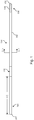
- the intravascular device 100 includes a flexible elongate member 102 having a distal portion 104 adjacent a distal end 105 and a proximal portion 106 adjacent a proximal end 107.
- a component 108 is positioned within the distal portion 104 of the flexible elongate member 102 proximal of the distal tip 105.
- the component 108 is representative of one or more electronic, optical, or electro-optical components.
- the component 108 is a pressure sensor, a flow sensor, a temperature sensor, an imaging element, an optical fiber, an ultrasound transducer, a reflector, a mirror, a prism, an ablation element, an RF electrode, a conductor, and/or combinations thereof.
- the specific type of component or combination of components can be selected based on an intended use of the intravascular device.
- the component 108 is positioned less than 10 cm, less than 5, or less than 3 cm from the distal tip 105.
- the component 108 is positioned within a housing of the flexible elongate member 102.
- the housing is a separate component secured to the flexible elongate member 102 in some instances. In other instances, the housing is integrally formed as a part of the flexible elongate member 102.
- the intravascular device 100 also includes a connector 110 adjacent the proximal portion 106 of the device.
- the connector 110 is spaced from the proximal end 107 of the flexible elongate member 102 by a distance 112.
- the distance 112 is between 0% and 50% of the total length of the flexible elongate member 102.
- the total length of the flexible elongate member can be any length, in some embodiments the total length is between about 1300 mm and about 4000 mm, with some specific embodiments have a length of 1400 mm, 1900 mm, and 3000 mm.
- the connector 110 is positioned at the proximal end 107. In other instances, the connector 110 is spaced from the proximal end 107.
- the connector 110 is spaced from the proximal end 107 between about 0 mm and about 1400 mm. In some specific embodiments, the connector 110 is spaced from the proximal end by a distance of 0 mm, 300 mm, and 1400 mm.
- the connector 110 is configured to facilitate communication between the intravascular device 100 and another device. More specifically, in some embodiments the connector 110 is configured to facilitate communication of data obtained by the component 108 to another device, such as a computing device or processor. Accordingly, in some embodiments the connector 110 is an electrical connector. In such instances, the connector 110 provides an electrical connection to one or more electrical conductors that extend along the length of the flexible elongate member 102 and are electrically coupled to the component 108. In other embodiments, the connector 110 is an optical connector. In such instances, the connector 110 provides an optical connection to one or more optical communication pathways (e.g., fiber optic cable) that extend along the length of the flexible elongate member 102 and are optically coupled to the component 108.
- optical communication pathways e.g., fiber optic cable
- the connector 110 provides both electrical and optical connections to both electrical conductor(s) and optical communication pathway(s) coupled to the component 108.
- component 108 is comprised of a plurality of elements in some instances.
- the connector 110 is configured to provide a physical connection to another device, either directly or indirectly.
- the connector 110 is configured to facilitate wireless communication between the intravascular device 100 and another device.
- any current or future developed wireless protocol(s) may be utilized.
- the connector 110 facilitates both physical and wireless connection to another device.
- the connector 110 provides a connection between the component 108 of the intravascular device 100 and an external device.
- one or more electrical conductors, one or more optical pathways, and/or combinations thereof extend along the length of the flexible elongate member 102 between the connector 110 and the component 108 to facilitate communication between the connector 110 and the component 108.
- any number of electrical conductors, optical pathways, and/or combinations thereof can extend along the length of the core of the flexible elongate member 102 between the connector 110 and the component 108.
- between one and ten electrical conductors and/or optical pathways extend along the length of the flexible elongate member 102 between the connector 110 and the component 108.
- the number of communication pathways and the number of electrical conductors and optical pathways extending along the length the flexible elongate member 102 is determined by the desired functionality of the component 108 and the corresponding elements that define component 108 to provide such functionality.
- Figs. 2-6 shown therein are aspects of the intravascular devices of the present disclosure that include a core member formed of multiple materials.
- one of the major issues associated with existing functional guide wires is poor mechanical performance as compared to frontline guide wires. This performance loss is due in a large part to the typical design of the guide wires that severely limits the space available for the core or core wire due to the need to run the communication lines along the length of the device between the core wire and a surrounding hypotube.
- the embodiments described below include either three or six electrical conductors embedded in an outer layer surrounding a core member formed of multiple materials, which may include conductive materials suitable for use as a communication line.
- intravascular devices that include virtually any number of electrical conductors extending along the length of the core wire.
- the intravascular device will include between 1 and 10 communication pathways extending between a proximal portion and a distal portion of the intravascular device.
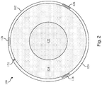
- a cross-sectional end view of the intravascular device 100 taken along section line 2-2 of Fig. 1 is shown according to an embodiment of the present disclosure.
- the flexible elongate member 102 is defined by a core member 120.
- the core member 120 is defined by an inner section 122 and an outer section 124 that surrounds the inner section.
- the inner section 122 is formed of a first material and the outer section 124 is formed of a second material that is different than the first material.
- the inner section 122 and the outer section 124 can be formed from any suitable materials, including without limitation stainless steel, nickel and titanium alloys (such as Nitinol), polyetheretherketone, 304V stainless steel, MP35N, L605, and/or other suitable metallic or polymeric materials.
- suitable materials including without limitation stainless steel, nickel and titanium alloys (such as Nitinol), polyetheretherketone, 304V stainless steel, MP35N, L605, and/or other suitable metallic or polymeric materials.
- the inner section 122 and the outer section 124 are formed of two different metals that are co-drawn together to form the core member 120.
- the inner section 122 is formed from a superelastic metal, such as Nitinol, Nitinol alloys, NiTiCo, and other suitable materials, that may have a high yield strength to improve durability of the working distal portion of the intravascular device 100.
- the outer section 124 is formed from a metal having a higher modulus than that of the inner section 122, such as stainless steel, MP35N, L605, or other suitable metal, to improve the stiffness of the overall intravascular device 100 for better push strength and/or column strength.
- the outer section 124 is formed of from a superelastic metal, such as Nitinol, Nitinol alloys, NiTiCo, and other suitable materials
- the inner section 122 is formed from a metal having a higher modulus, such as stainless steel, MP35N, L605, or other suitable metal.
- An outer layer 126 is formed around the core member 120 in some instances.
- the outer layer 126 can be formed of a suitable polymeric material.
- the outer layer 126 is coated onto the wire using standard wire coating techniques in some instances.
- conductors 128 are introduced into the coating process such that they become completely coated in the polymeric material.
- the outer layer 126 may be formed of any suitable polymeric material, and a preferred material is polyimide.
- Each of the conductors 128 is formed of a conductive material, such as copper, gold, silver, platinum, or other suitable conductive material. Generally, the size of the conductors 128 is selected to allow the conductors 128 to be fully embedded within the material forming the outer layer 126.
- the conductors 128 are space substantially equally around a circumference of the flexible elongate member 102.
- the conductors 128 may be embedded in any suitable manner and/or pattern, including symmetric, non-symmetric, geometric, and non-geometric patterns.
- a final coating that can provide lubricity is applied to the outer surface of the outer layer 126.
- the coating extends along a majority of the length of the flexible elongate member between the proximal portion 106 and the distal portion 104.
- the coating can be a suitable hydrophilic or hydrophobic coating.
- the coating provides increased lubricity.
- Exemplary coating materials include, without limitation, PTFE impregnated polyimide, silicone-based coatings, and hydrophilic based coatings. Generally, the coating will be a very thin layer of material.
- the coating has a thickness less than about 0,0254 mm (0.0010"), less than about 0,00254 mm (0.0001"), and/or less than about 0,00127 mm (0.00005").
- a lubricious coating is blended with or mixed into the outer layer 126 to create a lubricious layer without a definite break between materials.
- the outer layer 126 can be utilized to electrically isolate the conductors 128 from each other and the core member 120. As a result, each of the conductors 128 and/or the core member 120 can be utilized as an independent electrical communication pathway of the intravascular device 100.
- the conductors 128 are coated with an insulating material prior to being embedded within the outer layer 126. That is, an insulated conductor is provided separately and then embedded within the outer layer 126 during formation of the core member. In other instances, the outer layer 126 and conductors 128 are formed as part of an integrated process.
- the outer diameter of the core member 120 is sized to allow for formation of one or more outer layers, such as outer layer 126, around the core member 120. Accordingly, where the intravascular device 100 is intended to have an outer diameter of approximately 0,3556 mm (0.014"), the outer diameter of the core member 120 can be between about 0,1524 mm (0.006") and about 0,3429 mm (0.0135"), between about 0,2032 mm (0.008") and about 0,3302 mm (0.013"), or between about 0,2286 mm (0.009") and about 0,3048 mm (0.012"). Further, the inner section 122 and the outer section 124 can be formed in any ratio of sizes to define the overall diameter of the core member 120.
- the inner section 122 can be larger, by volume or cross-sectional area, than the outer section 124, or vice versa. Accordingly, in some instances the inner section 122 of the core member has an outer diameter between about 0,0254 mm (0.001") and about 0,3048 mm (0.012"), while the outer section of the core member has a thickness (from its inner surface adjacent the inner section 122 to its outer surface adjacent the outer layer 126) between about 0,0254 mm (0.001") and about 0,1651 mm (0.0065").
- the relative sizes of the inner section 122 and the outer section 124 can be selected based on the materials used for each section.
- the relative sizes of the inner section 122 and the outer section 124 may be dependent upon the desired outer diameter of the intravascular device 100, which as discussed above may include sizes of approximately 0,3556 mm (0.014"), 0,4572 mm (0.018"), 0,889 mm (0.035”), 0,9652 mm (0.038”) and/or other suitable sizes.
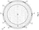
- FIG. 3 a cross-sectional end view of the intravascular device 100 taken along section line 3-3 of Fig. 1 is shown according to another embodiment of the present disclosure.
- Fig. 3 shows an alternative embodiment to that of Fig. 2 .
- Fig. 3 illustrates an embodiment where the inner section 122 of the core member 120 has an increased diameter such that the outer section 124 defines a smaller percentage of the core member 120.
- Fig. 3 illustrates an embodiment with six conductors 128 embedded within the outer layer 126.
- Fig. 3 illustrates an embodiment where the material used to form the inner and outer sections 122, 124 has been reversed relative to the embodiment of Fig. 2 .
- Fig. 3 shows merely one exemplary alternative embodiment and that the intravascular devices of the present disclosure can use any variation of core materials, core diameter sizes, ratios of core materials, number of conductors, arrangement of conductors, and/or other variations in the design.
- Fig. 4 shown therein is diagrammatic side view of the flexible elongate member 102 according to an embodiment of the present disclosure.
- the flexible elongate member 102 is shown with the distal portion 104 and proximal portion 106 having been processed for use in the intravascular device 100.
- the distal portion 104 has been processed to expose a portion of the conductors 128 for electrical coupling to component 108 and shape the inner core member 120 to facilitate coupling to one or more flexible members and/or a sensor housing, facilitate physical coupling to the component 108, increase the flexibility of the distal tip of the intravascular device 102, and/or otherwise configure the characteristics of the distal portion of the intravascular device 102 for use.
- the main body of the flexible elongate member 102 has a diameter 130.
- the diameter 130 is approximately equal to the maximum desired outer diameter of the intravascular device 100. Accordingly, in some particular implementations the diameter 130 is about 0,3556 mm (0.014"), 0,4572 mm (0.018"), or 0,889 mm (0.035").
- the distal portion 104 of the flexible elongate member 102 has been processed to include a portion 132 extending distally from the main body of the flexible elongate member 102 and a portion 134 extended distally from portion 132. In some instances, the distal portion 104 is processed by grinding, etching, ablating, and/or otherwise removing portions of the outer layer 126 and/or the core member 120.
- portions of the outer layer 126 have been removed to expose sections of the embedded conductors 128.
- the component 108 can be electrically coupled to the conductors 128 (e.g., using solder, leads, additional conductors (insulated in some instances)).
- the conductors 128 are exposed for electrical coupling to component 108 at an end surface extending perpendicular to the longitudinal axis of the flexible elongate member 102. That is, the conductors 128 are not exposed along the length of the flexible elongate member 102 (as shown in Fig. 4 ), but rather are exposed at an end surface of the flexible elongate member (similar to what is shown in Figs. 2 and 3 ), which may occur at an intermediate transition point(s), such as the end of main body or end of section 132 and/or an end of the outer layer 126.
- section 132 has a tapered profile resulting from removal of the outer layer 126 and at least portions of the outer section 124 and/or the inner section 122 of the core member 120. In this manner, section 132 tapers the outer profile of the core member 120 from the diameter 130 of the main body of the flexible elongate member 102 to the reduced diameter 136 of section 134.
- the outer layer 126 and the outer section 124 of the core member 120 are removed to reduce the stiffness and increase the flexibility of the flexible elongate member 102.
- the diameter 136 of section 134 is between about 10% and about 80% of the diameter 130, with some particular embodiments being between about 30% and about 60% of the diameter 130.
- the diameter 136 of section 134 is between about 0,0254 mm (0.001") and about 0,127 mm (0.005") for a 0,3556 mm (0.014") outer diameter intravascular device, with 0,0508 mm (0.002") being utilized in some particular embodiments; between about 0,0254 mm (0.001") and about 0,2032 mm (0.008") for a 0,4572 mm (0.018") outer diameter intravascular device, with 0,0762 mm (0.003") being utilized in some particular embodiments; and between about 0,0635 mm (0.0025”) and about 0,254 mm (0.010") for a 0,889 mm (0.035”) outer diameter intravascular device, with 0,1778 mm (0.007”) being utilized in some particular embodiments.
- section 132 and/or section 134 are shaped in a manner to facilitate coupling to additional elements of the intravascular device 100, including component 108, a housing for component 108, flexible members (coils, polymer tubes, and/or coil-embedded polymer tubes), and/or combinations thereof.
- the sections 132 and 134 can include tapers, recesses, projections, and/or other structural features to facilitate coupling to other elements.
- the core member 120 is coupled to a distal section, intermediate section, and/or proximal section similar to those described in one or more of U.S. Patent No. 5,125,137 , U.S. Patent No. 5,873,835 , U.S. Patent No.
- the component 108 can be mounted within a distal section of the intravascular device 100 using any suitable technique, including without limitation those disclosed in one or more of U.S. Patent No. 5,125,137 , U.S. Patent No. 5,873,835 , U.S. Patent No. 6,106,476 , U.S. Patent No. 6,551,250 , U.S. Patent Application No. 13/931,052, filed June 28, 2013 , U.S. Patent Application No.
- the proximal portion 106 of the core member 120 has been processed to expose the embedded conductors 128.
- one or more connectors can be electrically coupled to the conductors 128 (e.g., using solder, leads, additional conductors (insulated in some instances) to define connector 110 of the intravascular device 100.
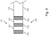
- proximal portion 106 of the intravascular device 100 formed over the flexible elongate member 102 of Fig. 4 according to an embodiment of the present disclosure.
- three conductive bands 138 are separated by insulators 140 to define the connector 110 of the intravascular device 100.
- the conductive bands 138 are printed onto the flexible elongate member 102 by electrically printing or plating of a conductive material over the exposed portions of the conductors 128.
- the conductive bands 138 are formed such that they have a uniform outer diameter matching the desired outer diameter of the intravascular device 100 and/or the outer diameter of connector in some implementations.
- each of the conductive bands 128 are exposed and then coated with an insulator material, such as polyimide. Then each individual conductor 128 is exposed (e.g., via laser ablation) at staggered locations along the length of the flexible elongate member 102 that represent where the conductive bands 138 will be formed. In this manner, each conductive band 138 is electrically coupled to a single conductor 128 and electrically isolated from the remaining conductors 128. If desired, it is possible to electrically couple a conductive band 138 to more than one of the conductors 128.
- an insulator material such as polyimide
- any desired pattern of conductive material may be placed onto the flexible elongate member 102 to define the conductive bands 138.
- the conductive bands 138 can be solid, multiple rings, a spiral, and/or any other pattern that provides the optimum functionality.
- the conductive bands 138 are preformed cylindrical members that are positioned over the corresponding exposed sections of the conductors 128 and electrically coupled to the conductors using solder or other suitable techniques.
- the conductive bands 138 are swaged and/or laser welded in place.
- the insulating material utilized for insulators 140 may be any suitable insulating material.
- each of the three conductive bands 138 is electrically coupled to a single one of the conductors 128 and electrically isolated from the others (e.g., by one or more insulating layers).
- the conductors 128 are exposed from the outer layer 126 only in locations along the length of the core member where the conductor 128 is to be coupled to the conductive band.
- a reference ring may be formed at a proximal or distal end of the flexible elongate member 102 to determine where the conductors 128 are positioned relative to the circumference/outer surface of the flexible elongate member 102 to facilitate selective exposure of only portions of the conductors 128.
- conductive bands 138 there are numerous ways for electrically coupling the conductive bands 138 to the conductors 128 in an isolated manner. Further, it should be noted that in some instances an additional conductive band is provided and electrically coupled to the core member 120. In yet other instances, a portion of the core member 120 itself defines a conductive band.
- the distal portion 104 of the intravascular device 100 formed over the core member 120 of Fig. 4 according to an embodiment of the present disclosure.
- the distal portion 104 includes a flexible element 150 extending from the main body of the flexible elongate member 102 over sections 132 and 134 to the component 108 (or a housing containing component 108).
- the flexible element 150 may be a coil, a polymer tubing, and/or a coil-embedded polymer tubing.
- the distal portion 104 also includes a flexible element 152 extending distally from the component 108 (or a housing containing component 108) to the distal tip 105 of the intravascular device 100.
- the flexible element 152 may be a coil, a polymer tubing, and/or a coil-embedded polymer tubing.
- the flexible element 152 is radiopaque and/or includes a radiopaque tip.
- a flow sensor is positioned at the distal tip 105 of the intravascular device 100.
- the distal portion 104 of the intravascular device 100 may include features similar to those described in any of the patents and applications above, but utilizing the core member 120 of the present disclosure having embedded conductors 124 as the core wire of the intravascular device.
- the distal portion 104 can include one or more radiopaque markers 154.
- the radiopaque markers 154 can be utilized to facilitate co-registration of the measurements obtained with the intravascular device 100 to corresponding images of the vessel, including angiography, x-ray, CT scans, IVUS, OCT, and/or other imaging modalities.
- co-registration is performed as disclosed in one or more of U.S. Patent No. 7,930,014 , titled "VASCULAR IMAGE CO-REGISTRATION," U.S. Provisional Patent Application No.
- the radiopaque markers 154 can be formed of any radiopaque material. In some instances, the radiopaque markers 154 are coils formed of a radiopaque material. There may be any number of radiopaque markers 154, including one, two (as shown), three, or more. In some implementations, the radiopaque markers 154 are located proximal of the component 108 and its associated housing, if any. Further, in some instances the radiopaque markers 154 are elongated such that they have a greater length than typical balloon or stent markers, to allow the radiopaque markers 154 of the intravascular device 100 to be distinguished from the markers of other elements that may be positioned in the same region of the vessel. In some instances, the radiopaque markers 154 have a length along the longitudinal axis of the intravascular device 100 of between about 3 mm and about 10 mm, with some particular implementations having a length of about 5 mm.
- the sensor(s) of the intravascular device 100 provide a mechanism to obtain intraluminal measurements within a body lumen and are connected to the one or more conductive bands on the intravascular device, which transmit and receive signals from the sensor(s).
- the guide wire of the present disclosure can include a pressure sensor, a flow sensor, a temperature sensor or combinations thereof.
- the guide wire can be a combination guide wire that includes both a pressure sensor and a flow sensor.
- Pressure sensors can be used to measure pressure within the lumen and flow sensors can be used to measure the velocity of blood flow.
- Temperature sensors can measure the temperature of a lumen.
- a guide wire with both a pressure sensor and a flow sensor provides a desirable environment in which to calculate fractional flow reserve (FFR) or other pressure ratio calculations using pressure readings, and coronary flow reserve (CFR) using flow readings.
- Guide wires with two or more sensors can be made by increasing the number of conductive wires embedded within the core member.
- the core member 120 may also be utilized as a conductor in some embodiments. Such embodiments provide enough conductive pathways to facilitate the use of at least two sensors with the intravascular device 100.
- the ability to measure and compare both the pressure and velocity flow and create an index of hyperemic stenosis resistance significantly improves the diagnostic accuracy of this ischemic testing. It has been shown that distal pressure and velocity measurements, particularly regarding the pressure drop-velocity relationship such as Fractional Flow reserve (FFR), Coronary flow reserve (CFR) and combined P-V curves, reveal information about the stenosis severity.
- FFR Fractional Flow reserve
- CFR Coronary flow reserve
- the guide wire may be advanced to a location on the distal side of the stenosis. The pressure and flow velocity may then be measured at a first flow state. Then, the flow rate may be significantly increased, for example by the use of drugs such as adenosine, and the pressure and flow measured in this second, hyperemic, flow state.
- the pressure and flow relationships at these two flow states are then compared to assess the severity of the stenosis and provide improved guidance for any coronary interventions.
- the ability to take the pressure and flow measurements at the same location and same time with the combination tip sensor, improves the accuracy of these pressure-velocity loops and therefore improves the accuracy of the diagnostic information.
- a pressure sensor can be mounted, for example, on a distal portion of the guide wire.
- the pressure sensor can be formed of a crystal semiconductor material having a recess therein and forming a diaphragm bordered by a rim.
- a reinforcing member is bonded to the crystal and reinforces the rim of the crystal and has a cavity therein underlying the diaphragm and exposed to the diaphragm.
- a resistor having opposite ends is carried by the crystal and has a portion thereof overlying a portion of the diaphragm. Electrical conductor wires of the sensor are connected to a conductive band in the guide wire. Additional details of suitable pressure sensors that may be used with devices of the present disclosure are described in U.S. Pat. No. 6,106,476 . U.S. Pat. No. 6,106,476 also describes suitable methods for coupling the pressure sensor to a guide wire. Those methods are applicable to coupling the sensor to the conductive bands in guide wires of the present disclosure.
- the guide wire of the present disclosure includes a flow sensor.
- the flow sensor can be used to measure blood flow velocity within the vessel, which can be used to assess coronary flow reserve (CFR).
- CFR coronary flow reserve
- the flow sensor can be, for example, an ultrasound transducer, a Doppler flow sensor or any other suitable flow sensor, disposed at or in close proximity to the distal tip of the guide wire.
- the ultrasound transducer may be any suitable transducer, and may be mounted in the distal end using any conventional method, including the manner described in U.S. Pat. No. 5,125,137 , 6,551,250 and 5,873,835 .
- Guide wires of the present disclosure can be connected to an instrument, such as a computing device (e.g. a laptop, desktop, or tablet computer) or a physiology monitor, that converts the signals received by the sensors into pressure and velocity readings.
- the instrument can further calculate Coronary Flow Reserve (CFR) and Fractional Flow Reserve (FFR) and provide the readings and calculations to a user via a user interface.
- CFR Coronary Flow Reserve
- FFR Fractional Flow Reserve
- a user interacts with a visual interface to view images associated with the data obtained by the intravascular devices of the present disclosure.
- Input from a user e.g., parameters or a selection
- the selection can be rendered into a visible display.
Description
- The present disclosure relates to intravascular devices, systems, and methods. In some embodiments, the intravascular devices are sensing guide wires that include a core wire formed of multiple materials.
- Heart disease is very serious and often requires emergency operations to save lives. A main cause of heart disease is the accumulation of plaque inside the blood vessels, which eventually occludes the blood vessels. Common treatment options available to open up the occluded vessel include balloon angioplasty, rotational atherectomy, and intravascular stents. Traditionally, surgeons have relied on X-ray fluoroscopic images that are planar images showing the external shape of the silhouette of the lumen of blood vessels to guide treatment. Unfortunately, with X-ray fluoroscopic images, there is a great deal of uncertainty about the exact extent and orientation of the stenosis responsible for the occlusion, making it difficult to find the exact location of the stenosis. In addition, though it is known that restenosis can occur at the same place, it is difficult to check the condition inside the vessels after surgery with X-ray.
- A currently accepted technique for assessing the severity of a stenosis in a blood vessel, including ischemia causing lesions, is fractional flow reserve (FFR). FFR is a calculation of the ratio of a distal pressure measurement (taken on the distal side of the stenosis) relative to a proximal pressure measurement (taken on the proximal side of the stenosis). FFR provides an index of stenosis severity that allows determination as to whether the blockage limits blood flow within the vessel to an extent that treatment is required. The normal value of FFR in a healthy vessel is 1.00, while values less than about 0.80 are generally deemed significant and require treatment.
- Often intravascular catheters and guide wires are utilized to measure the pressure within the blood vessel, visualize the inner lumen of the blood vessel, and/or otherwise obtain data related to the blood vessel. To date, guide wires containing pressure sensors, imaging elements, and/or other electronic, optical, or electro-optical components have suffered from reduced performance characteristics compared to standard guide wires that do not contain such components. For example, the handling performance of previous guide wires containing electronic components have been hampered, in some instances, by the limited space available for the core wire after accounting for the space needed for the conductors or communication lines of the electronic component(s), the stiffness of the rigid housing containing the electronic component(s), and/or other limitations associated with providing the functionality of the electronic components in the limited space available within a guide wire. Further, due to its small diameter, in many instances the proximal connector portion of the guide wire (i.e., the connector(s) that facilitate communication between the electronic component(s) of the guide wire and an associated controller or processor) is fragile and prone to kinking, which can destroy the functionality of the guide wire. For this reason, surgeons are reluctant to remove the proximal connector from the guide wire during a procedure for fear of breaking the guide wire when reattaching the proximal connector. Having the guide wire coupled to the proximal connector further limits the maneuverability and handling of the guide wire.
- Further, a problem with existing pressure and flow guide wires is that they require a complex assembly of many discrete components. That complex assembly process has limitations on design performance of the guide wire. The use of separate conductive wires running down the length of the wire reduces the space available for more supportive cores and can result in numerous issues during use due to poor solder joints with conductive bands, electrical shorts due to insulation issues, and breakage of the delicate conductive wires.
-
US 2013/0274619 A1 discloses a measuring system which includes an elongated sleeve having a compact diameter configured to be delivered over a standard guide wire and able to be flexibly threaded into a tortuous or diseased vascular pathway of a human. Sensor(s) are located at a distal end of the sleeve and measure physiological parameter(s) inside the human. The sleeve measuring system has an outer diameter of approximately 20 mils or less and is capable of accommodating the standard guide wire, typically 14 mils in diameter. - Document
US 2014/0055443 discloses a device according to the preamble of claim 1. - Accordingly, there remains a need for improved intravascular devices, systems, and methods that include one or more electronic, optical, or electro-optical components.
- The present disclosure is directed to intravascular devices, systems, and methods that include a guide wire having a core wire formed of multiple materials.
- The present disclosure provides a more robust sensing guide wire that avoids the assembly and performance issues of prior sensing guide wires. Guide wires of the present disclosure have a core wire formed of multiple materials. For example, in some implementations the core wire is formed of two different metals co-drawn to form the core wire. The core wire is covered by an outer layer embedded with electrical conductors. The electrical conductors extend along the length of the guide wire and act as the electrical pathway for sensor signals. The electrical conductors can be electrically isolated from the core wire by an insulating material of the outer layer. The electrical conductors can be exposed by removing surrounding portions of the outer layer (e.g., by ablating, cutting, etching, etc.) at specific locations to facilitate the creation of electrical connections. In that regard, a proximal section of each conductor can be electrically coupled to a proximal connector (e.g., one or more conductive bands), while a distal section of the conductor can be electrically coupled to a sensing element. In that regard, the distal section of the conductor may be exposed for electrical connection as part of a distal shaping process. In some instances, the distal shaping process includes removing one of the materials of the core wire. For example, where two metals are co-drawn such that one metal surrounds the other metal, portions of the outer metal layer and/or the inner metal layer can be removed (e.g., by grinding, etching, ablating, etc.) to define a desired structure for a distal section of the core.
- Any type of sensor can be connected to guide wires of the present disclosure. In certain embodiments, only a single sensor is connected to the guide wire. In other embodiments, multiple sensors are connected to the guide wire. All of the sensors may be the same. Alternatively, the sensors may differ from each other and measure different characteristics inside a vessel. Exemplary sensors are pressure, flow, and temperature sensors. Generally, any type of pressure sensor may be used with the guide wires of the present disclosure, including piezoresistive, optical, and/or combinations thereof. Similarly, any type of flow sensor may be used with guide wires of the present disclosure. In certain embodiments, the flow sensor includes an ultrasound transducer, such as a Doppler ultrasound transducer. The guide wires can include both a pressure sensor and a flow sensor.
- The present disclosure provides intravascular devices that are stronger and more durable than existing designs, while also easier to manufacture. For example the guide wires of the present disclosure can eliminate the need for a hypotube and substantially reduce the need for adhesives and solder in formation of the guide wire. Reducing the number of components necessary to assemble the guide wires improves the robustness of the assembled guide wire by eliminating a multitude of processes and connection points that can create failure conditions. Embodiments of the present disclosure utilize a core member formed of two different materials and surrounded by an outer layer embedded with one or more electrical conductors that facilitates the use of a larger core that provides better handling, strength, and durability than existing designs, which reduces the likelihood of unwanted bending, kinking, and/or other damage to the intravascular device that can be detrimental to the function of the device.
- Additional aspects, features, and advantages of the present disclosure will become apparent from the following detailed description.
- A sensing guidewire in accordance with the invention is defined in claim 1.
- A method of forming a sensing guidewire in accordance with the invention is defined in claim 11.
- Illustrative embodiments of the present disclosure will be described with reference to the accompanying drawings, of which:
-
FIG. 1 is a diagrammatic, schematic side view of an intravascular device according to an embodiment of the present disclosure. -
FIG. 2 is a cross-sectional end view of the intravascular device ofFig. 1 according to an embodiment of the present disclosure. -
FIG. 3 is a cross-sectional end view of the intravascular device ofFig. 1 according to another embodiment of the present disclosure. -
FIG. 4 is a diagrammatic, schematic side view of portions of an intravascular device according to an embodiment of the present disclosure. -
FIG. 5 is a diagrammatic, schematic side view of a proximal portion of an intravascular device according to an embodiment of the present disclosure. -
FIG. 6 is a diagrammatic, schematic side view of a distal portion of an intravascular device according to an embodiment of the present disclosure. - For the purposes of promoting an understanding of the principles of the present disclosure, reference will now be made to the embodiments illustrated in the drawings, and specific language will be used to describe the same. It is nevertheless understood that no limitation to the scope of the disclosure is intended. Any alterations and further modifications to the described devices, systems, and methods, and any further application of the principles of the present disclosure are fully contemplated and included within the present disclosure as would normally occur to one skilled in the art to which the disclosure relates. In particular, it is fully contemplated that the features, components, and/or steps described with respect to one embodiment may be combined with the features, components, and/or steps described with respect to other embodiments of the present disclosure. For the sake of brevity, however, the numerous iterations of these combinations will not be described separately.
- As used herein, "flexible elongate member" or "elongate flexible member" includes at least any thin, long, flexible structure that can be inserted into the vasculature of a patient. While the illustrated embodiments of the "flexible elongate members" of the present disclosure have a cylindrical profile with a circular cross-sectional profile that defines an outer diameter of the flexible elongate member, in other instances all or a portion of the flexible elongate members may have other geometric cross-sectional profiles (e.g., oval, rectangular, square, elliptical, etc.) or non-geometric cross-sectional profiles. Flexible elongate members include, for example, guide wires and catheters. In that regard, catheters may or may not include a lumen extending along its length for receiving and/or guiding other instruments. If the catheter includes a lumen, the lumen may be centered or offset with respect to the cross-sectional profile of the device.
- In most embodiments, the flexible elongate members of the present disclosure include one or more electronic, optical, or electro-optical components. For example, without limitation, a flexible elongate member may include one or more of the following types of components: a pressure sensor, a flow sensor, a temperature sensor, an imaging element, an optical fiber, an ultrasound transducer, a reflector, a mirror, a prism, an ablation element, an RF electrode, a conductor, and/or combinations thereof. Generally, these components are configured to obtain data related to a vessel or other portion of the anatomy in which the flexible elongate member is disposed. Often the components are also configured to communicate the data to an external device for processing and/or display. In some aspects, embodiments of the present disclosure include imaging devices for imaging within the lumen of a vessel, including both medical and non-medical applications. However, some embodiments of the present disclosure are particularly suited for use in the context of human vasculature. Imaging of the intravascular space, particularly the interior walls of human vasculature can be accomplished by a number of different techniques, including ultrasound (often referred to as intravascular ultrasound ("IVUS") and intracardiac echocardiography ("ICE")) and optical coherence tomography ("OCT"). In other instances, infrared, thermal, or other imaging modalities are utilized.
- The electronic, optical, and/or electro-optical components of the present disclosure are often disposed within a distal portion of the flexible elongate member. As used herein, "distal portion" of the flexible elongate member includes any portion of the flexible elongate member from the mid-point to the distal tip. As flexible elongate members can be solid, some embodiments of the present disclosure will include a housing portion at the distal portion for receiving the electronic components. Such housing portions can be tubular structures attached to the distal portion of the elongate member. Some flexible elongate members are tubular and have one or more lumens in which the electronic components can be positioned within the distal portion.
- The electronic, optical, and/or electro-optical components and the associated communication lines are sized and shaped to allow for the diameter of the flexible elongate member to be very small. For example, the outside diameter of the elongate member, such as a guide wire or catheter, containing one or more electronic, optical, and/or electro-optical components as described herein are between about 0.0007" (0.0178 mm) and about 0.118" (3.0 mm), with some particular embodiments having outer diameters of approximately 0.014" (0.3556 mm), approximately 0.018" (0.4572 mm), and approximately 0.035" (0.889 mm). As such, the flexible elongate members incorporating the electronic, optical, and/or electro-optical component(s) of the present application are suitable for use in a wide variety of lumens within a human patient besides those that are part or immediately surround the heart, including veins and arteries of the extremities, renal arteries, blood vessels in and around the brain, and other lumens.
- "Connected" and variations thereof as used herein includes direct connections, such as being glued or otherwise fastened directly to, on, within, etc. another element, as well as indirect connections where one or more elements are disposed between the connected elements.
- "Secured" and variations thereof as used herein includes methods by which an element is directly secured to another element, such as being glued or otherwise fastened directly to, on, within, etc. another element, as well as indirect techniques of securing two elements together where one or more elements are disposed between the secured elements.
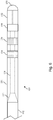
- Referring now to
Fig. 1 , shown therein is a portion of anintravascular device 100 according to an embodiment of the present disclosure. In that regard, theintravascular device 100 includes a flexibleelongate member 102 having adistal portion 104 adjacent adistal end 105 and aproximal portion 106 adjacent aproximal end 107. Acomponent 108 is positioned within thedistal portion 104 of the flexibleelongate member 102 proximal of thedistal tip 105. Generally, thecomponent 108 is representative of one or more electronic, optical, or electro-optical components. In that regard, thecomponent 108 is a pressure sensor, a flow sensor, a temperature sensor, an imaging element, an optical fiber, an ultrasound transducer, a reflector, a mirror, a prism, an ablation element, an RF electrode, a conductor, and/or combinations thereof. The specific type of component or combination of components can be selected based on an intended use of the intravascular device. In some instances, thecomponent 108 is positioned less than 10 cm, less than 5, or less than 3 cm from thedistal tip 105. In some instances, thecomponent 108 is positioned within a housing of the flexibleelongate member 102. In that regard, the housing is a separate component secured to the flexibleelongate member 102 in some instances. In other instances, the housing is integrally formed as a part of the flexibleelongate member 102. - The
intravascular device 100 also includes aconnector 110 adjacent theproximal portion 106 of the device. In that regard, theconnector 110 is spaced from theproximal end 107 of the flexibleelongate member 102 by adistance 112. Generally, thedistance 112 is between 0% and 50% of the total length of the flexibleelongate member 102. While the total length of the flexible elongate member can be any length, in some embodiments the total length is between about 1300 mm and about 4000 mm, with some specific embodiments have a length of 1400 mm, 1900 mm, and 3000 mm. Accordingly, in some instances theconnector 110 is positioned at theproximal end 107. In other instances, theconnector 110 is spaced from theproximal end 107. For example, in some instances theconnector 110 is spaced from theproximal end 107 between about 0 mm and about 1400 mm. In some specific embodiments, theconnector 110 is spaced from the proximal end by a distance of 0 mm, 300 mm, and 1400 mm. - The
connector 110 is configured to facilitate communication between theintravascular device 100 and another device. More specifically, in some embodiments theconnector 110 is configured to facilitate communication of data obtained by thecomponent 108 to another device, such as a computing device or processor. Accordingly, in some embodiments theconnector 110 is an electrical connector. In such instances, theconnector 110 provides an electrical connection to one or more electrical conductors that extend along the length of the flexibleelongate member 102 and are electrically coupled to thecomponent 108. In other embodiments, theconnector 110 is an optical connector. In such instances, theconnector 110 provides an optical connection to one or more optical communication pathways (e.g., fiber optic cable) that extend along the length of the flexibleelongate member 102 and are optically coupled to thecomponent 108. Further, in some embodiments theconnector 110 provides both electrical and optical connections to both electrical conductor(s) and optical communication pathway(s) coupled to thecomponent 108. In that regard, it should be noted thatcomponent 108 is comprised of a plurality of elements in some instances. Theconnector 110 is configured to provide a physical connection to another device, either directly or indirectly. In some instances, theconnector 110 is configured to facilitate wireless communication between theintravascular device 100 and another device. Generally, any current or future developed wireless protocol(s) may be utilized. In yet other instances, theconnector 110 facilitates both physical and wireless connection to another device. - As noted above, in some instances the
connector 110 provides a connection between thecomponent 108 of theintravascular device 100 and an external device. Accordingly, in some embodiments one or more electrical conductors, one or more optical pathways, and/or combinations thereof extend along the length of the flexibleelongate member 102 between theconnector 110 and thecomponent 108 to facilitate communication between theconnector 110 and thecomponent 108. Generally, any number of electrical conductors, optical pathways, and/or combinations thereof can extend along the length of the core of the flexibleelongate member 102 between theconnector 110 and thecomponent 108. In some instances, between one and ten electrical conductors and/or optical pathways extend along the length of the flexibleelongate member 102 between theconnector 110 and thecomponent 108. The number of communication pathways and the number of electrical conductors and optical pathways extending along the length the flexibleelongate member 102 is determined by the desired functionality of thecomponent 108 and the corresponding elements that definecomponent 108 to provide such functionality. - Referring now to
Figs. 2-6 , shown therein are aspects of the intravascular devices of the present disclosure that include a core member formed of multiple materials. In that regard, one of the major issues associated with existing functional guide wires is poor mechanical performance as compared to frontline guide wires. This performance loss is due in a large part to the typical design of the guide wires that severely limits the space available for the core or core wire due to the need to run the communication lines along the length of the device between the core wire and a surrounding hypotube. For the sake of clarity and simplicity, the embodiments described below include either three or six electrical conductors embedded in an outer layer surrounding a core member formed of multiple materials, which may include conductive materials suitable for use as a communication line. Those skilled in the art will recognize that the concepts are applicable to intravascular devices that include virtually any number of electrical conductors extending along the length of the core wire. However, in most implementations the intravascular device will include between 1 and 10 communication pathways extending between a proximal portion and a distal portion of the intravascular device. - Referring more specifically to
Fig. 2 , a cross-sectional end view of theintravascular device 100 taken along section line 2-2 ofFig. 1 is shown according to an embodiment of the present disclosure. As shown, the flexibleelongate member 102 is defined by acore member 120. Thecore member 120 is defined by aninner section 122 and anouter section 124 that surrounds the inner section. Theinner section 122 is formed of a first material and theouter section 124 is formed of a second material that is different than the first material. Generally, theinner section 122 and theouter section 124 can be formed from any suitable materials, including without limitation stainless steel, nickel and titanium alloys (such as Nitinol), polyetheretherketone, 304V stainless steel, MP35N, L605, and/or other suitable metallic or polymeric materials. - According to the invention, the
inner section 122 and theouter section 124 are formed of two different metals that are co-drawn together to form thecore member 120. In some particular instances, theinner section 122 is formed from a superelastic metal, such as Nitinol, Nitinol alloys, NiTiCo, and other suitable materials, that may have a high yield strength to improve durability of the working distal portion of theintravascular device 100. In some instances, theouter section 124 is formed from a metal having a higher modulus than that of theinner section 122, such as stainless steel, MP35N, L605, or other suitable metal, to improve the stiffness of the overallintravascular device 100 for better push strength and/or column strength. In other instances, theouter section 124 is formed of from a superelastic metal, such as Nitinol, Nitinol alloys, NiTiCo, and other suitable materials, and theinner section 122 is formed from a metal having a higher modulus, such as stainless steel, MP35N, L605, or other suitable metal. - An
outer layer 126 is formed around thecore member 120 in some instances. Theouter layer 126 can be formed of a suitable polymeric material. In that regard, theouter layer 126 is coated onto the wire using standard wire coating techniques in some instances. As the thickness of the coating is built up,conductors 128 are introduced into the coating process such that they become completely coated in the polymeric material. Theouter layer 126 may be formed of any suitable polymeric material, and a preferred material is polyimide. Each of theconductors 128 is formed of a conductive material, such as copper, gold, silver, platinum, or other suitable conductive material. Generally, the size of theconductors 128 is selected to allow theconductors 128 to be fully embedded within the material forming theouter layer 126. In certain embodiments, theconductors 128 are space substantially equally around a circumference of the flexibleelongate member 102. However, theconductors 128 may be embedded in any suitable manner and/or pattern, including symmetric, non-symmetric, geometric, and non-geometric patterns. - In certain embodiments, after reaching a desired outer diameter, a final coating that can provide lubricity is applied to the outer surface of the
outer layer 126. In some embodiments, the coating extends along a majority of the length of the flexible elongate member between theproximal portion 106 and thedistal portion 104. The coating can be a suitable hydrophilic or hydrophobic coating. In some implementations, the coating provides increased lubricity. Exemplary coating materials include, without limitation, PTFE impregnated polyimide, silicone-based coatings, and hydrophilic based coatings. Generally, the coating will be a very thin layer of material. For example, in some implementations the coating has a thickness less than about 0,0254 mm (0.0010"), less than about 0,00254 mm (0.0001"), and/or less than about 0,00127 mm (0.00005"). In some arrangements, a lubricious coating is blended with or mixed into theouter layer 126 to create a lubricious layer without a definite break between materials. - The
outer layer 126 can be utilized to electrically isolate theconductors 128 from each other and thecore member 120. As a result, each of theconductors 128 and/or thecore member 120 can be utilized as an independent electrical communication pathway of theintravascular device 100. In some instances, theconductors 128 are coated with an insulating material prior to being embedded within theouter layer 126. That is, an insulated conductor is provided separately and then embedded within theouter layer 126 during formation of the core member. In other instances, theouter layer 126 andconductors 128 are formed as part of an integrated process. - The outer diameter of the
core member 120 is sized to allow for formation of one or more outer layers, such asouter layer 126, around thecore member 120. Accordingly, where theintravascular device 100 is intended to have an outer diameter of approximately 0,3556 mm (0.014"), the outer diameter of thecore member 120 can be between about 0,1524 mm (0.006") and about 0,3429 mm (0.0135"), between about 0,2032 mm (0.008") and about 0,3302 mm (0.013"), or between about 0,2286 mm (0.009") and about 0,3048 mm (0.012"). Further, theinner section 122 and theouter section 124 can be formed in any ratio of sizes to define the overall diameter of thecore member 120. That is, theinner section 122 can be larger, by volume or cross-sectional area, than theouter section 124, or vice versa. Accordingly, in some instances theinner section 122 of the core member has an outer diameter between about 0,0254 mm (0.001") and about 0,3048 mm (0.012"), while the outer section of the core member has a thickness (from its inner surface adjacent theinner section 122 to its outer surface adjacent the outer layer 126) between about 0,0254 mm (0.001") and about 0,1651 mm (0.0065"). The relative sizes of theinner section 122 and theouter section 124 can be selected based on the materials used for each section. It is understood that the relative sizes of theinner section 122 and theouter section 124 may be dependent upon the desired outer diameter of theintravascular device 100, which as discussed above may include sizes of approximately 0,3556 mm (0.014"), 0,4572 mm (0.018"), 0,889 mm (0.035"), 0,9652 mm (0.038") and/or other suitable sizes. - Referring now to
Fig. 3 , a cross-sectional end view of theintravascular device 100 taken along section line 3-3 ofFig. 1 is shown according to another embodiment of the present disclosure. In that regard,Fig. 3 shows an alternative embodiment to that ofFig. 2 . In particular,Fig. 3 illustrates an embodiment where theinner section 122 of thecore member 120 has an increased diameter such that theouter section 124 defines a smaller percentage of thecore member 120. Further,Fig. 3 illustrates an embodiment with sixconductors 128 embedded within theouter layer 126. Further still,Fig. 3 illustrates an embodiment where the material used to form the inner andouter sections Fig. 2 . It is understood thatFig. 3 shows merely one exemplary alternative embodiment and that the intravascular devices of the present disclosure can use any variation of core materials, core diameter sizes, ratios of core materials, number of conductors, arrangement of conductors, and/or other variations in the design. - Referring now to
Fig. 4 , shown therein is diagrammatic side view of the flexibleelongate member 102 according to an embodiment of the present disclosure. In that regard, the flexibleelongate member 102 is shown with thedistal portion 104 andproximal portion 106 having been processed for use in theintravascular device 100. In particular, thedistal portion 104 has been processed to expose a portion of theconductors 128 for electrical coupling tocomponent 108 and shape theinner core member 120 to facilitate coupling to one or more flexible members and/or a sensor housing, facilitate physical coupling to thecomponent 108, increase the flexibility of the distal tip of theintravascular device 102, and/or otherwise configure the characteristics of the distal portion of theintravascular device 102 for use. - As shown the main body of the flexible
elongate member 102 has adiameter 130. Generally, thediameter 130 is approximately equal to the maximum desired outer diameter of theintravascular device 100. Accordingly, in some particular implementations thediameter 130 is about 0,3556 mm (0.014"), 0,4572 mm (0.018"), or 0,889 mm (0.035"). As shown, thedistal portion 104 of the flexibleelongate member 102 has been processed to include aportion 132 extending distally from the main body of the flexibleelongate member 102 and aportion 134 extended distally fromportion 132. In some instances, thedistal portion 104 is processed by grinding, etching, ablating, and/or otherwise removing portions of theouter layer 126 and/or thecore member 120. - As shown, portions of the
outer layer 126 have been removed to expose sections of the embeddedconductors 128. By exposing theconductors 128, thecomponent 108 can be electrically coupled to the conductors 128 (e.g., using solder, leads, additional conductors (insulated in some instances)). In some implementations, theconductors 128 are exposed for electrical coupling tocomponent 108 at an end surface extending perpendicular to the longitudinal axis of the flexibleelongate member 102. That is, theconductors 128 are not exposed along the length of the flexible elongate member 102 (as shown inFig. 4 ), but rather are exposed at an end surface of the flexible elongate member (similar to what is shown inFigs. 2 and3 ), which may occur at an intermediate transition point(s), such as the end of main body or end ofsection 132 and/or an end of theouter layer 126. - In the illustrated embodiment,
section 132 has a tapered profile resulting from removal of theouter layer 126 and at least portions of theouter section 124 and/or theinner section 122 of thecore member 120. In this manner,section 132 tapers the outer profile of thecore member 120 from thediameter 130 of the main body of the flexibleelongate member 102 to the reduceddiameter 136 ofsection 134. In some embodiments, insection 134 theouter layer 126 and theouter section 124 of thecore member 120 are removed to reduce the stiffness and increase the flexibility of the flexibleelongate member 102. Accordingly, in some instances, thediameter 136 ofsection 134 is between about 10% and about 80% of thediameter 130, with some particular embodiments being between about 30% and about 60% of thediameter 130. Accordingly, in some implementations, thediameter 136 ofsection 134 is between about 0,0254 mm (0.001") and about 0,127 mm (0.005") for a 0,3556 mm (0.014") outer diameter intravascular device, with 0,0508 mm (0.002") being utilized in some particular embodiments; between about 0,0254 mm (0.001") and about 0,2032 mm (0.008") for a 0,4572 mm (0.018") outer diameter intravascular device, with 0,0762 mm (0.003") being utilized in some particular embodiments; and between about 0,0635 mm (0.0025") and about 0,254 mm (0.010") for a 0,889 mm (0.035") outer diameter intravascular device, with 0,1778 mm (0.007") being utilized in some particular embodiments. - In some instances,
section 132 and/orsection 134 are shaped in a manner to facilitate coupling to additional elements of theintravascular device 100, includingcomponent 108, a housing forcomponent 108, flexible members (coils, polymer tubes, and/or coil-embedded polymer tubes), and/or combinations thereof. In that regard, thesections core member 120 is coupled to a distal section, intermediate section, and/or proximal section similar to those described in one or more ofU.S. Patent No. 5,125,137 ,U.S. Patent No. 5,873,835 ,U.S. Patent No. 6,106,476 ,U.S. Patent No. 6,551,250 , andU.S. Patent Application No. 13/931,052, filed June 28, 2013 U.S. Patent Application No. 14/143,304, filed December 30, 2013 component 108 can be mounted within a distal section of theintravascular device 100 using any suitable technique, including without limitation those disclosed in one or more ofU.S. Patent No. 5,125,137 ,U.S. Patent No. 5,873,835 ,U.S. Patent No. 6,106,476 ,U.S. Patent No. 6,551,250 ,U.S. Patent Application No. 13/931,052, filed June 28, 2013 U.S. Patent Application No. 14/135,117, filed December 19, 2013 U.S. Patent Application No. 14/137,364, filed December 20, 2013 U.S. Patent Application No. 14/139,543, filed December 23, 2013 U.S. Patent Application No. 14,143,304, filed December 30, 2013 - As shown, the
proximal portion 106 of thecore member 120 has been processed to expose the embeddedconductors 128. By exposing theconductors 128, one or more connectors can be electrically coupled to the conductors 128 (e.g., using solder, leads, additional conductors (insulated in some instances) to defineconnector 110 of theintravascular device 100. - Referring now to
Fig. 5 , shown therein is theproximal portion 106 of theintravascular device 100 formed over the flexibleelongate member 102 ofFig. 4 according to an embodiment of the present disclosure. As shown, threeconductive bands 138 are separated byinsulators 140 to define theconnector 110 of theintravascular device 100. In some instances, theconductive bands 138 are printed onto the flexibleelongate member 102 by electrically printing or plating of a conductive material over the exposed portions of theconductors 128. In that regard, theconductive bands 138 are formed such that they have a uniform outer diameter matching the desired outer diameter of theintravascular device 100 and/or the outer diameter of connector in some implementations. To facilitate formation of each of theconductive bands 128 in an electrically isolated manner relative to theother conductors 128, the embeddedconductors 128 are exposed and then coated with an insulator material, such as polyimide. Then eachindividual conductor 128 is exposed (e.g., via laser ablation) at staggered locations along the length of the flexibleelongate member 102 that represent where theconductive bands 138 will be formed. In this manner, eachconductive band 138 is electrically coupled to asingle conductor 128 and electrically isolated from the remainingconductors 128. If desired, it is possible to electrically couple aconductive band 138 to more than one of theconductors 128. - Any desired pattern of conductive material may be placed onto the flexible
elongate member 102 to define theconductive bands 138. For example, theconductive bands 138 can be solid, multiple rings, a spiral, and/or any other pattern that provides the optimum functionality. In some instances, theconductive bands 138 are preformed cylindrical members that are positioned over the corresponding exposed sections of theconductors 128 and electrically coupled to the conductors using solder or other suitable techniques. In some embodiments, theconductive bands 138 are swaged and/or laser welded in place. The insulating material utilized forinsulators 140 may be any suitable insulating material. - In the illustrated embodiment, each of the three
conductive bands 138 is electrically coupled to a single one of theconductors 128 and electrically isolated from the others (e.g., by one or more insulating layers). In some instances, theconductors 128 are exposed from theouter layer 126 only in locations along the length of the core member where theconductor 128 is to be coupled to the conductive band. A reference ring may be formed at a proximal or distal end of the flexibleelongate member 102 to determine where theconductors 128 are positioned relative to the circumference/outer surface of the flexibleelongate member 102 to facilitate selective exposure of only portions of theconductors 128. Those skilled in the art will recognize that there are numerous ways for electrically coupling theconductive bands 138 to theconductors 128 in an isolated manner. Further, it should be noted that in some instances an additional conductive band is provided and electrically coupled to thecore member 120. In yet other instances, a portion of thecore member 120 itself defines a conductive band. - Referring now to
Fig. 6 , shown therein is thedistal portion 104 of theintravascular device 100 formed over thecore member 120 ofFig. 4 according to an embodiment of the present disclosure. As shown, thedistal portion 104 includes aflexible element 150 extending from the main body of the flexibleelongate member 102 oversections flexible element 150 may be a coil, a polymer tubing, and/or a coil-embedded polymer tubing. Thedistal portion 104 also includes aflexible element 152 extending distally from the component 108 (or a housing containing component 108) to thedistal tip 105 of theintravascular device 100. Again, theflexible element 152 may be a coil, a polymer tubing, and/or a coil-embedded polymer tubing. In some instances, theflexible element 152 is radiopaque and/or includes a radiopaque tip. In some implementations, a flow sensor is positioned at thedistal tip 105 of theintravascular device 100. Generally, thedistal portion 104 of theintravascular device 100 may include features similar to those described in any of the patents and applications above, but utilizing thecore member 120 of the present disclosure having embeddedconductors 124 as the core wire of the intravascular device. - As also shown in
Fig. 6 , thedistal portion 104 can include one or moreradiopaque markers 154. In that regard, theradiopaque markers 154 can be utilized to facilitate co-registration of the measurements obtained with theintravascular device 100 to corresponding images of the vessel, including angiography, x-ray, CT scans, IVUS, OCT, and/or other imaging modalities. In some implementations, co-registration is performed as disclosed in one or more ofU.S. Patent No. 7,930,014 , titled "VASCULAR IMAGE CO-REGISTRATION,"U.S. Provisional Patent Application No. 61/747,480 U.S. Provisional Patent Application No. 61/856,509 U.S. Provisional Patent Application No. 61/895,909 - The
radiopaque markers 154 can be formed of any radiopaque material. In some instances, theradiopaque markers 154 are coils formed of a radiopaque material. There may be any number ofradiopaque markers 154, including one, two (as shown), three, or more. In some implementations, theradiopaque markers 154 are located proximal of thecomponent 108 and its associated housing, if any. Further, in some instances theradiopaque markers 154 are elongated such that they have a greater length than typical balloon or stent markers, to allow theradiopaque markers 154 of theintravascular device 100 to be distinguished from the markers of other elements that may be positioned in the same region of the vessel. In some instances, theradiopaque markers 154 have a length along the longitudinal axis of theintravascular device 100 of between about 3 mm and about 10 mm, with some particular implementations having a length of about 5 mm. - As discussed above with respect to
component 108, the sensor(s) of theintravascular device 100 provide a mechanism to obtain intraluminal measurements within a body lumen and are connected to the one or more conductive bands on the intravascular device, which transmit and receive signals from the sensor(s). For example, the guide wire of the present disclosure can include a pressure sensor, a flow sensor, a temperature sensor or combinations thereof. The guide wire can be a combination guide wire that includes both a pressure sensor and a flow sensor. Pressure sensors can be used to measure pressure within the lumen and flow sensors can be used to measure the velocity of blood flow. Temperature sensors can measure the temperature of a lumen. A guide wire with both a pressure sensor and a flow sensor provides a desirable environment in which to calculate fractional flow reserve (FFR) or other pressure ratio calculations using pressure readings, and coronary flow reserve (CFR) using flow readings. Guide wires with two or more sensors can be made by increasing the number of conductive wires embedded within the core member. In addition, thecore member 120 may also be utilized as a conductor in some embodiments. Such embodiments provide enough conductive pathways to facilitate the use of at least two sensors with theintravascular device 100. - The ability to measure and compare both the pressure and velocity flow and create an index of hyperemic stenosis resistance significantly improves the diagnostic accuracy of this ischemic testing. It has been shown that distal pressure and velocity measurements, particularly regarding the pressure drop-velocity relationship such as Fractional Flow reserve (FFR), Coronary flow reserve (CFR) and combined P-V curves, reveal information about the stenosis severity. For example, in use, the guide wire may be advanced to a location on the distal side of the stenosis. The pressure and flow velocity may then be measured at a first flow state. Then, the flow rate may be significantly increased, for example by the use of drugs such as adenosine, and the pressure and flow measured in this second, hyperemic, flow state. The pressure and flow relationships at these two flow states are then compared to assess the severity of the stenosis and provide improved guidance for any coronary interventions. The ability to take the pressure and flow measurements at the same location and same time with the combination tip sensor, improves the accuracy of these pressure-velocity loops and therefore improves the accuracy of the diagnostic information.
- A pressure sensor can be mounted, for example, on a distal portion of the guide wire. The pressure sensor can be formed of a crystal semiconductor material having a recess therein and forming a diaphragm bordered by a rim. A reinforcing member is bonded to the crystal and reinforces the rim of the crystal and has a cavity therein underlying the diaphragm and exposed to the diaphragm. A resistor having opposite ends is carried by the crystal and has a portion thereof overlying a portion of the diaphragm. Electrical conductor wires of the sensor are connected to a conductive band in the guide wire. Additional details of suitable pressure sensors that may be used with devices of the present disclosure are described in
U.S. Pat. No. 6,106,476 .U.S. Pat. No. 6,106,476 also describes suitable methods for coupling the pressure sensor to a guide wire. Those methods are applicable to coupling the sensor to the conductive bands in guide wires of the present disclosure. - In certain aspects, the guide wire of the present disclosure includes a flow sensor. The flow sensor can be used to measure blood flow velocity within the vessel, which can be used to assess coronary flow reserve (CFR). The flow sensor can be, for example, an ultrasound transducer, a Doppler flow sensor or any other suitable flow sensor, disposed at or in close proximity to the distal tip of the guide wire. The ultrasound transducer may be any suitable transducer, and may be mounted in the distal end using any conventional method, including the manner described in
U.S. Pat. No. 5,125,137 ,6,551,250 and5,873,835 . - Guide wires of the present disclosure can be connected to an instrument, such as a computing device (e.g. a laptop, desktop, or tablet computer) or a physiology monitor, that converts the signals received by the sensors into pressure and velocity readings. The instrument can further calculate Coronary Flow Reserve (CFR) and Fractional Flow Reserve (FFR) and provide the readings and calculations to a user via a user interface. In some embodiments, a user interacts with a visual interface to view images associated with the data obtained by the intravascular devices of the present disclosure. Input from a user (e.g., parameters or a selection) are received by a processor in an electronic device. The selection can be rendered into a visible display.
- Persons skilled in the art will also recognize that the apparatus, systems, and methods described above can be modified in various ways. Accordingly, persons of ordinary skill in the art will appreciate that the embodiments encompassed by the present disclosure are not limited to the particular exemplary embodiments described above. In that regard, although illustrative embodiments have been shown and described, a wide range of modification, change, and substitution is contemplated in the foregoing disclosure. It is understood that such variations may be made to the foregoing without departing from the scope of the present disclosure. Accordingly, it is appropriate that the appended claims be construed broadly and in a manner consistent with the present disclosure.
Claims (14)
- A sensing guide wire, comprising:a core member (120) having an inner section (122) and an outer section (124) surrounding the inner section (122), wherein the inner section (122) is formed of a first material and the outer section (124) is formed of a second material that is different than the first material;a polymer outer layer (126) surrounding the core member (120); anda sensing element coupled to a distal portion (104) of the core member (120),characterised in that the inner section (122) and the outer section (124) are formed of two different metals that are co-drawn together to form the core member (120).wherein the polymer outer layer (126) includes at least one communication line embedded therein,wherein the at least one communication line includes a conductor (128);wherein the conductor (128) is fully embedded within the material forming the outer layer (126), andwherein the sensing element is communicatively coupled to the at least one communication line,
- The guide wire of claim 1, wherein the sensing element includes at least one of a pressure sensor and a flow sensor.
- The guide wire of claim 1, wherein the first material is Nitinol or other nickel titanium alloy.
- The guide wire of claim 3, wherein the second material is stainless steel or a high modulus alloy.
- The guide wire of claim 1, wherein the first material is stainless steel.
- The guide wire of claim 5, wherein the second material is Nitinol.
- The guide wire of claim 1, wherein the guide wire has an outer diameter of between about 0.3556 mm (0.014") and 0.9652 mm (0.038").
- The guide wire of claim 1, wherein at least the outer section (124) is removed from the distal portion (104) of the core member (120).
- The guide wire of claim 8, wherein the sensing element is positioned within a housing coupled to the distal portion (104) of the core member (120).
- The guide wire of claim 9, further comprising a flexible element positioned around the distal portion (104) of the core member (120) proximal of the housing.
- A method of forming a sensing guide wire, the method comprising:forming a core member (120) having an inner section (122) and an outer section (124) surrounding the inner section (122), wherein the inner section (122) is formed of a first material and the outer section (124) is formed of a second material that is different than the first material;surrounding the core member (120) with a polymer outer layer (126), wherein the polymer outer layer (126) includes at least one communication line embedded therein;wherein the at least one communication line includes a conductor (128);wherein the conductor (128) is fully embedded within the material forming the outer layer (126);communicatively coupling the sensing element to the at least one communication line; andcoupling a sensing element to a distal portion (104) of the core member (120),characterised in that the inner section (122) and the outer section (124) are formed of two different metals that are co-drawn together to form the core member (120).
- The method of claim 11, wherein at least one of the first material and the second material is Nitinol and wherein at least one of the first material and the second material is stainless steel.
- The method of claim 11, further comprising shaping the distal portion (104) of the core member (120) by removing at least the outer section (124) from the distal portion (104) of the core member (120).
- The method of claim 13, wherein coupling the sensing element to the distal portion (104) of the core member (120) includes positioning the sensing element within a housing coupled to the distal portion (104) of the core member (120).
Applications Claiming Priority (2)
| Application Number | Priority Date | Filing Date | Title |
|---|---|---|---|
| US201461970777P | 2014-03-26 | 2014-03-26 | |
| PCT/US2015/022020 WO2015148383A1 (en) | 2014-03-26 | 2015-03-23 | Intravascular devices, systems, and methods having a core wire formed of multiple materials |
Publications (3)
| Publication Number | Publication Date |
|---|---|
| EP3122240A1 EP3122240A1 (en) | 2017-02-01 |
| EP3122240A4 EP3122240A4 (en) | 2017-03-29 |
| EP3122240B1 true EP3122240B1 (en) | 2019-05-08 |
Family
ID=54188865
Family Applications (1)
| Application Number | Title | Priority Date | Filing Date |
|---|---|---|---|
| EP15768252.7A Active EP3122240B1 (en) | 2014-03-26 | 2015-03-23 | Intravascular devices, systems, and methods having a core wire formed of multiple materials |
Country Status (5)
| Country | Link |
|---|---|
| US (1) | US10441754B2 (en) |
| EP (1) | EP3122240B1 (en) |
| JP (1) | JP2017512566A (en) |
| CN (1) | CN106132293A (en) |
| WO (1) | WO2015148383A1 (en) |
Families Citing this family (15)
| Publication number | Priority date | Publication date | Assignee | Title |
|---|---|---|---|---|
| EP3397158B1 (en) * | 2015-12-28 | 2023-08-02 | The Trustees of Princeton University | Elastic filament velocity sensor |
| US11173283B2 (en) | 2016-03-30 | 2021-11-16 | Koninklijke Philips N.V. | Torque devices for use with intravascular devices and associated systems and methods |
| US11058388B2 (en) * | 2016-05-20 | 2021-07-13 | Perimeter Medical Imaging, Inc. | Method and system for combining microscopic imaging with X-Ray imaging |
| EP3602571A1 (en) * | 2017-03-30 | 2020-02-05 | Koninklijke Philips N.V. | Functional measurement patient interface module (pim) for distributed wireless intraluminal sensing systems |
| WO2018204586A1 (en) * | 2017-05-05 | 2018-11-08 | Cryterion Medical, Inc. | Corewire for mapping catheter for intravascular catheter system |
| CN209136594U (en) * | 2018-11-05 | 2019-07-23 | 苏州润迈德医疗科技有限公司 | New catheter for invasive angiosthenia monitoring |
| EP4161360B1 (en) | 2020-06-09 | 2023-10-25 | Philips Image Guided Therapy Corporation | Physiology sensing intraluminal device with reinforced multi-filar bundle and associated assembling method |
| JP2023533830A (en) | 2020-07-15 | 2023-08-04 | コーニンクレッカ フィリップス エヌ ヴェ | Intraluminal physiological sensing device with embedded conformal conductor |
| WO2023194208A1 (en) | 2022-04-07 | 2023-10-12 | Koninklijke Philips N.V. | Continuous electrical trace in intraluminal device and associated devices, systems, and methods |
| WO2023194399A1 (en) | 2022-04-08 | 2023-10-12 | Koninklijke Philips N.V. | Electrical traces along core wire for intraluminal physiology sensing guidewire and associated devices, systems, and methods |
| WO2023198672A1 (en) | 2022-04-13 | 2023-10-19 | Koninklijke Philips N.V. | Sensor housing for improved accuracy and electrical reliability |
| WO2023198628A1 (en) | 2022-04-13 | 2023-10-19 | Koninklijke Philips N.V. | Flex circuit for electrical connection in intraluminal device and associated devices, systems, and methods |
| WO2023202934A1 (en) | 2022-04-20 | 2023-10-26 | Koninklijke Philips N.V. | Flex circuit around core wire in intraluminal device and associated devices, systems, and methods |
| WO2023202904A1 (en) | 2022-04-22 | 2023-10-26 | Koninklijke Philips N.V. | Core wire with elongate structures for conductors in intraluminal device and associated devices, systems, and methods |
| WO2024013367A1 (en) | 2022-07-15 | 2024-01-18 | Koninklijke Philips N.V. | Sensor mount with embedded conductors for different sensor |
Citations (2)
| Publication number | Priority date | Publication date | Assignee | Title |
|---|---|---|---|---|
| US20140005560A1 (en) * | 2012-06-28 | 2014-01-02 | Volcano Corporation | Connection Structures for Intravascular Devices and Associated Systems and Methods |
| US20140005543A1 (en) * | 2012-06-28 | 2014-01-02 | Volcano Corporation | Intravascular Devices, Systems, and Methods |
Family Cites Families (26)
| Publication number | Priority date | Publication date | Assignee | Title |
|---|---|---|---|---|
| US5125137A (en) | 1990-09-06 | 1992-06-30 | Cardiometrics, Inc. | Method for providing a miniature ultrasound high efficiency transducer assembly |
| US5873835A (en) | 1993-04-29 | 1999-02-23 | Scimed Life Systems, Inc. | Intravascular pressure and flow sensor |
| DE69534748T2 (en) | 1994-09-02 | 2006-11-02 | Volcano Corp. (n.d, Ges.d.Staates Delaware), Rancho Cordova | ULTRAMINIATUR PRESSURE SENSOR AND GUIDE WIRE THEREFORE |
| US6329069B1 (en) * | 1995-07-26 | 2001-12-11 | Surface Genesis, Inc. | Composite structure and devices made from same and method |
| US6039699A (en) | 1996-01-22 | 2000-03-21 | Cordis Corporation | Stiff catheter guidewire with flexible distal portion |
| US7645242B1 (en) * | 1998-12-31 | 2010-01-12 | Advanced Cardiovascular Systems, Inc. | Composite guidewire with drawn and filled tube construction |
| US7047082B1 (en) * | 1999-09-16 | 2006-05-16 | Micronet Medical, Inc. | Neurostimulating lead |
| US6551250B2 (en) | 2001-03-29 | 2003-04-22 | Hassan Khalil | Transit time thermodilution guidewire system for measuring coronary flow velocity |
| JP4222775B2 (en) | 2001-06-15 | 2009-02-12 | ラディ・メディカル・システムズ・アクチェボラーグ | Measuring device that can be inserted into living organisms |
| US8257278B2 (en) | 2002-05-14 | 2012-09-04 | Advanced Cardiovascular Systems, Inc. | Metal composite guide wire |
| US7930014B2 (en) | 2005-01-11 | 2011-04-19 | Volcano Corporation | Vascular image co-registration |
| US20070025514A1 (en) * | 2005-06-06 | 2007-02-01 | Ruediger Lawaczeck | X-ray arrangement for graphic display of an object under examination and use of the x-ray arrangement |
| ATE469600T1 (en) | 2006-04-28 | 2010-06-15 | Radi Medical Systems | SENSOR AND GUIDE WIRE ASSEMBLY |
| US20070255145A1 (en) | 2006-04-28 | 2007-11-01 | Radi Medical Systems Ab | Sensor and guide wire assembly |
| US20080077050A1 (en) * | 2006-09-08 | 2008-03-27 | Radi Medical Systems Ab | Electrical connector for medical device |
| US8128579B2 (en) | 2007-11-02 | 2012-03-06 | Boston Scientific Scimed, Inc. | Guidewires with improved fatigue life and methods of making the same |
| US20100274619A1 (en) | 2009-04-24 | 2010-10-28 | International Business Machines Corporation | Enhanced Calendaring Notification |
| US8764683B2 (en) * | 2010-12-29 | 2014-07-01 | Mediguide Ltd. | Medical device guidewire with a position sensor |
| US9399944B2 (en) * | 2011-02-07 | 2016-07-26 | Nissan Motor Co., Ltd. | Control device for multi-cylinder internal combustion engine |
| US20130274619A1 (en) * | 2011-11-01 | 2013-10-17 | Sensorcath, Inc. | Systems and methods for a low-profile vascular pressure measurement device |
| US9358370B2 (en) * | 2012-03-12 | 2016-06-07 | Medtronic Vascular, Inc. | Guidewire with integral radiopaque markers |
| JP6509117B2 (en) | 2012-08-31 | 2019-05-08 | ボルケーノ コーポレイション | Mounting structure for components of intravascular devices |
| US20140180141A1 (en) | 2012-12-21 | 2014-06-26 | Volcano Corporation | Mounting Structures for Components of Intravascular Devices |
| US20140187980A1 (en) | 2012-12-28 | 2014-07-03 | Volcano Corporation | Hypotube Sensor Mount for Sensored Guidewire |
| EP3545829B1 (en) | 2012-12-31 | 2022-03-30 | Philips Image Guided Therapy Corporation | Method of forming a guidewire |
| US20140187984A1 (en) | 2012-12-31 | 2014-07-03 | Volcano Corporation | In-Wall Hypotube Sensor Mount for Sensored Guidewire |
-
2015
- 2015-03-19 US US14/663,185 patent/US10441754B2/en active Active
- 2015-03-23 CN CN201580016195.1A patent/CN106132293A/en active Pending
- 2015-03-23 WO PCT/US2015/022020 patent/WO2015148383A1/en active Application Filing
- 2015-03-23 JP JP2016558180A patent/JP2017512566A/en active Pending
- 2015-03-23 EP EP15768252.7A patent/EP3122240B1/en active Active
Patent Citations (2)
| Publication number | Priority date | Publication date | Assignee | Title |
|---|---|---|---|---|
| US20140005560A1 (en) * | 2012-06-28 | 2014-01-02 | Volcano Corporation | Connection Structures for Intravascular Devices and Associated Systems and Methods |
| US20140005543A1 (en) * | 2012-06-28 | 2014-01-02 | Volcano Corporation | Intravascular Devices, Systems, and Methods |
Also Published As
| Publication number | Publication date |
|---|---|
| US10441754B2 (en) | 2019-10-15 |
| EP3122240A1 (en) | 2017-02-01 |
| US20150273187A1 (en) | 2015-10-01 |
| JP2017512566A (en) | 2017-05-25 |
| CN106132293A (en) | 2016-11-16 |
| EP3122240A4 (en) | 2017-03-29 |
| WO2015148383A1 (en) | 2015-10-01 |
Similar Documents
| Publication | Publication Date | Title |
|---|---|---|
| US11324410B2 (en) | Intravascular devices, systems, and methods having a core wire with embedded conductors | |
| EP3122240B1 (en) | Intravascular devices, systems, and methods having a core wire formed of multiple materials | |
| US11864918B2 (en) | Intravascular devices, systems, and methods having separate sections with engaged core components | |
| EP3545829B1 (en) | Method of forming a guidewire | |
| US20220160305A1 (en) | Intravascular devices, systems, and methods having a core wire with multiple flattened sections | |
| JP6509117B2 (en) | Mounting structure for components of intravascular devices | |
| US10350389B2 (en) | Intravascular devices, systems, and methods having a radiopaque patterned flexible tip | |
| US20160073957A1 (en) | Intravascular devices, systems, and methods having a sensing element embedded in adhesive | |
| JP7372907B2 (en) | Sensing guidewire with integrated proximal locking feature | |
| US20180184981A1 (en) | Intravascular devices systems and methods with a solid core proximal section and a slotted tubular distal section |
Legal Events
| Date | Code | Title | Description |
|---|---|---|---|
| STAA | Information on the status of an ep patent application or granted ep patent |
Free format text: STATUS: THE INTERNATIONAL PUBLICATION HAS BEEN MADE |
|
| PUAI | Public reference made under article 153(3) epc to a published international application that has entered the european phase |
Free format text: ORIGINAL CODE: 0009012 |
|
| STAA | Information on the status of an ep patent application or granted ep patent |
Free format text: STATUS: REQUEST FOR EXAMINATION WAS MADE |
|
| 17P | Request for examination filed |
Effective date: 20161026 |
|
| AK | Designated contracting states |
Kind code of ref document: A1 Designated state(s): AL AT BE BG CH CY CZ DE DK EE ES FI FR GB GR HR HU IE IS IT LI LT LU LV MC MK MT NL NO PL PT RO RS SE SI SK SM TR |
|
| AX | Request for extension of the european patent |
Extension state: BA ME |
|
| A4 | Supplementary search report drawn up and despatched |
Effective date: 20170228 |
|
| RIC1 | Information provided on ipc code assigned before grant |
Ipc: A61B 5/021 20060101AFI20170222BHEP Ipc: A61B 5/0215 20060101ALI20170222BHEP Ipc: A61B 5/026 20060101ALI20170222BHEP |
|
| DAV | Request for validation of the european patent (deleted) | ||
| DAX | Request for extension of the european patent (deleted) | ||
| STAA | Information on the status of an ep patent application or granted ep patent |
Free format text: STATUS: EXAMINATION IS IN PROGRESS |
|
| 17Q | First examination report despatched |
Effective date: 20180202 |
|
| GRAP | Despatch of communication of intention to grant a patent |
Free format text: ORIGINAL CODE: EPIDOSNIGR1 |
|
| STAA | Information on the status of an ep patent application or granted ep patent |
Free format text: STATUS: GRANT OF PATENT IS INTENDED |
|
| RAP1 | Party data changed (applicant data changed or rights of an application transferred) |
Owner name: VOLCANO CORPORATION |
|
| INTG | Intention to grant announced |
Effective date: 20181015 |
|
| GRAS | Grant fee paid |
Free format text: ORIGINAL CODE: EPIDOSNIGR3 |
|
| GRAA | (expected) grant |
Free format text: ORIGINAL CODE: 0009210 |
|
| STAA | Information on the status of an ep patent application or granted ep patent |
Free format text: STATUS: THE PATENT HAS BEEN GRANTED |
|
| AK | Designated contracting states |
Kind code of ref document: B1 Designated state(s): AL AT BE BG CH CY CZ DE DK EE ES FI FR GB GR HR HU IE IS IT LI LT LU LV MC MK MT NL NO PL PT RO RS SE SI SK SM TR |
|
| REG | Reference to a national code |
Ref country code: GB Ref legal event code: FG4D |
|
| REG | Reference to a national code |
Ref country code: CH Ref legal event code: EP Ref country code: AT Ref legal event code: REF Ref document number: 1128901 Country of ref document: AT Kind code of ref document: T Effective date: 20190515 |
|
| REG | Reference to a national code |
Ref country code: IE Ref legal event code: FG4D |
|
| REG | Reference to a national code |
Ref country code: DE Ref legal event code: R096 Ref document number: 602015029935 Country of ref document: DE |
|
| REG | Reference to a national code |
Ref country code: NL Ref legal event code: MP Effective date: 20190508 |
|
| REG | Reference to a national code |
Ref country code: LT Ref legal event code: MG4D |
|
| PG25 | Lapsed in a contracting state [announced via postgrant information from national office to epo] |
Ref country code: AL Free format text: LAPSE BECAUSE OF FAILURE TO SUBMIT A TRANSLATION OF THE DESCRIPTION OR TO PAY THE FEE WITHIN THE PRESCRIBED TIME-LIMIT Effective date: 20190508 Ref country code: PT Free format text: LAPSE BECAUSE OF FAILURE TO SUBMIT A TRANSLATION OF THE DESCRIPTION OR TO PAY THE FEE WITHIN THE PRESCRIBED TIME-LIMIT Effective date: 20190908 Ref country code: FI Free format text: LAPSE BECAUSE OF FAILURE TO SUBMIT A TRANSLATION OF THE DESCRIPTION OR TO PAY THE FEE WITHIN THE PRESCRIBED TIME-LIMIT Effective date: 20190508 Ref country code: HR Free format text: LAPSE BECAUSE OF FAILURE TO SUBMIT A TRANSLATION OF THE DESCRIPTION OR TO PAY THE FEE WITHIN THE PRESCRIBED TIME-LIMIT Effective date: 20190508 Ref country code: LT Free format text: LAPSE BECAUSE OF FAILURE TO SUBMIT A TRANSLATION OF THE DESCRIPTION OR TO PAY THE FEE WITHIN THE PRESCRIBED TIME-LIMIT Effective date: 20190508 Ref country code: NL Free format text: LAPSE BECAUSE OF FAILURE TO SUBMIT A TRANSLATION OF THE DESCRIPTION OR TO PAY THE FEE WITHIN THE PRESCRIBED TIME-LIMIT Effective date: 20190508 Ref country code: NO Free format text: LAPSE BECAUSE OF FAILURE TO SUBMIT A TRANSLATION OF THE DESCRIPTION OR TO PAY THE FEE WITHIN THE PRESCRIBED TIME-LIMIT Effective date: 20190808 Ref country code: SE Free format text: LAPSE BECAUSE OF FAILURE TO SUBMIT A TRANSLATION OF THE DESCRIPTION OR TO PAY THE FEE WITHIN THE PRESCRIBED TIME-LIMIT Effective date: 20190508 Ref country code: ES Free format text: LAPSE BECAUSE OF FAILURE TO SUBMIT A TRANSLATION OF THE DESCRIPTION OR TO PAY THE FEE WITHIN THE PRESCRIBED TIME-LIMIT Effective date: 20190508 |
|
| PG25 | Lapsed in a contracting state [announced via postgrant information from national office to epo] |
Ref country code: LV Free format text: LAPSE BECAUSE OF FAILURE TO SUBMIT A TRANSLATION OF THE DESCRIPTION OR TO PAY THE FEE WITHIN THE PRESCRIBED TIME-LIMIT Effective date: 20190508 Ref country code: BG Free format text: LAPSE BECAUSE OF FAILURE TO SUBMIT A TRANSLATION OF THE DESCRIPTION OR TO PAY THE FEE WITHIN THE PRESCRIBED TIME-LIMIT Effective date: 20190808 Ref country code: GR Free format text: LAPSE BECAUSE OF FAILURE TO SUBMIT A TRANSLATION OF THE DESCRIPTION OR TO PAY THE FEE WITHIN THE PRESCRIBED TIME-LIMIT Effective date: 20190809 Ref country code: RS Free format text: LAPSE BECAUSE OF FAILURE TO SUBMIT A TRANSLATION OF THE DESCRIPTION OR TO PAY THE FEE WITHIN THE PRESCRIBED TIME-LIMIT Effective date: 20190508 |
|
| REG | Reference to a national code |
Ref country code: AT Ref legal event code: MK05 Ref document number: 1128901 Country of ref document: AT Kind code of ref document: T Effective date: 20190508 |
|
| PG25 | Lapsed in a contracting state [announced via postgrant information from national office to epo] |
Ref country code: RO Free format text: LAPSE BECAUSE OF FAILURE TO SUBMIT A TRANSLATION OF THE DESCRIPTION OR TO PAY THE FEE WITHIN THE PRESCRIBED TIME-LIMIT Effective date: 20190508 Ref country code: AT Free format text: LAPSE BECAUSE OF FAILURE TO SUBMIT A TRANSLATION OF THE DESCRIPTION OR TO PAY THE FEE WITHIN THE PRESCRIBED TIME-LIMIT Effective date: 20190508 Ref country code: CZ Free format text: LAPSE BECAUSE OF FAILURE TO SUBMIT A TRANSLATION OF THE DESCRIPTION OR TO PAY THE FEE WITHIN THE PRESCRIBED TIME-LIMIT Effective date: 20190508 Ref country code: EE Free format text: LAPSE BECAUSE OF FAILURE TO SUBMIT A TRANSLATION OF THE DESCRIPTION OR TO PAY THE FEE WITHIN THE PRESCRIBED TIME-LIMIT Effective date: 20190508 Ref country code: DK Free format text: LAPSE BECAUSE OF FAILURE TO SUBMIT A TRANSLATION OF THE DESCRIPTION OR TO PAY THE FEE WITHIN THE PRESCRIBED TIME-LIMIT Effective date: 20190508 Ref country code: SK Free format text: LAPSE BECAUSE OF FAILURE TO SUBMIT A TRANSLATION OF THE DESCRIPTION OR TO PAY THE FEE WITHIN THE PRESCRIBED TIME-LIMIT Effective date: 20190508 |
|
| REG | Reference to a national code |
Ref country code: DE Ref legal event code: R097 Ref document number: 602015029935 Country of ref document: DE |
|
| PG25 | Lapsed in a contracting state [announced via postgrant information from national office to epo] |
Ref country code: IT Free format text: LAPSE BECAUSE OF FAILURE TO SUBMIT A TRANSLATION OF THE DESCRIPTION OR TO PAY THE FEE WITHIN THE PRESCRIBED TIME-LIMIT Effective date: 20190508 Ref country code: SM Free format text: LAPSE BECAUSE OF FAILURE TO SUBMIT A TRANSLATION OF THE DESCRIPTION OR TO PAY THE FEE WITHIN THE PRESCRIBED TIME-LIMIT Effective date: 20190508 |
|
| PLBE | No opposition filed within time limit |
Free format text: ORIGINAL CODE: 0009261 |
|
| STAA | Information on the status of an ep patent application or granted ep patent |
Free format text: STATUS: NO OPPOSITION FILED WITHIN TIME LIMIT |
|
| PG25 | Lapsed in a contracting state [announced via postgrant information from national office to epo] |
Ref country code: TR Free format text: LAPSE BECAUSE OF FAILURE TO SUBMIT A TRANSLATION OF THE DESCRIPTION OR TO PAY THE FEE WITHIN THE PRESCRIBED TIME-LIMIT Effective date: 20190508 |
|
| 26N | No opposition filed |
Effective date: 20200211 |
|
| PG25 | Lapsed in a contracting state [announced via postgrant information from national office to epo] |
Ref country code: PL Free format text: LAPSE BECAUSE OF FAILURE TO SUBMIT A TRANSLATION OF THE DESCRIPTION OR TO PAY THE FEE WITHIN THE PRESCRIBED TIME-LIMIT Effective date: 20190508 |
|
| PG25 | Lapsed in a contracting state [announced via postgrant information from national office to epo] |
Ref country code: SI Free format text: LAPSE BECAUSE OF FAILURE TO SUBMIT A TRANSLATION OF THE DESCRIPTION OR TO PAY THE FEE WITHIN THE PRESCRIBED TIME-LIMIT Effective date: 20190508 |
|
| PG25 | Lapsed in a contracting state [announced via postgrant information from national office to epo] |
Ref country code: MC Free format text: LAPSE BECAUSE OF FAILURE TO SUBMIT A TRANSLATION OF THE DESCRIPTION OR TO PAY THE FEE WITHIN THE PRESCRIBED TIME-LIMIT Effective date: 20190508 |
|
| REG | Reference to a national code |
Ref country code: CH Ref legal event code: PL |
|
| REG | Reference to a national code |
Ref country code: BE Ref legal event code: MM Effective date: 20200331 |
|
| PG25 | Lapsed in a contracting state [announced via postgrant information from national office to epo] |
Ref country code: LU Free format text: LAPSE BECAUSE OF NON-PAYMENT OF DUE FEES Effective date: 20200323 |
|
| PG25 | Lapsed in a contracting state [announced via postgrant information from national office to epo] |
Ref country code: CH Free format text: LAPSE BECAUSE OF NON-PAYMENT OF DUE FEES Effective date: 20200331 Ref country code: LI Free format text: LAPSE BECAUSE OF NON-PAYMENT OF DUE FEES Effective date: 20200331 Ref country code: IE Free format text: LAPSE BECAUSE OF NON-PAYMENT OF DUE FEES Effective date: 20200323 |
|
| PG25 | Lapsed in a contracting state [announced via postgrant information from national office to epo] |
Ref country code: BE Free format text: LAPSE BECAUSE OF NON-PAYMENT OF DUE FEES Effective date: 20200331 |
|
| PG25 | Lapsed in a contracting state [announced via postgrant information from national office to epo] |
Ref country code: MT Free format text: LAPSE BECAUSE OF FAILURE TO SUBMIT A TRANSLATION OF THE DESCRIPTION OR TO PAY THE FEE WITHIN THE PRESCRIBED TIME-LIMIT Effective date: 20190508 Ref country code: CY Free format text: LAPSE BECAUSE OF FAILURE TO SUBMIT A TRANSLATION OF THE DESCRIPTION OR TO PAY THE FEE WITHIN THE PRESCRIBED TIME-LIMIT Effective date: 20190508 |
|
| PGFP | Annual fee paid to national office [announced via postgrant information from national office to epo] |
Ref country code: FR Payment date: 20220325 Year of fee payment: 8 |
|
| PG25 | Lapsed in a contracting state [announced via postgrant information from national office to epo] |
Ref country code: MK Free format text: LAPSE BECAUSE OF FAILURE TO SUBMIT A TRANSLATION OF THE DESCRIPTION OR TO PAY THE FEE WITHIN THE PRESCRIBED TIME-LIMIT Effective date: 20190508 Ref country code: IS Free format text: LAPSE BECAUSE OF FAILURE TO SUBMIT A TRANSLATION OF THE DESCRIPTION OR TO PAY THE FEE WITHIN THE PRESCRIBED TIME-LIMIT Effective date: 20190908 |
|
| REG | Reference to a national code |
Ref country code: DE Ref legal event code: R081 Ref document number: 602015029935 Country of ref document: DE Owner name: PHILIPS IMAGE GUIDED THERAPY CORP., SAN DIEGO, US Free format text: FORMER OWNER: VOLCANO CORPORATION, SAN DIEGO, CA, US |
|
| PGFP | Annual fee paid to national office [announced via postgrant information from national office to epo] |
Ref country code: GB Payment date: 20230321 Year of fee payment: 9 Ref country code: DE Payment date: 20220628 Year of fee payment: 9 |
|
| PG25 | Lapsed in a contracting state [announced via postgrant information from national office to epo] |
Ref country code: FR Free format text: LAPSE BECAUSE OF NON-PAYMENT OF DUE FEES Effective date: 20230331 |