JP2018520218A - Optically clear adhesive that melts when warmed and its display assembly application - Google Patents
Optically clear adhesive that melts when warmed and its display assembly application Download PDFInfo
- Publication number
- JP2018520218A JP2018520218A JP2017557393A JP2017557393A JP2018520218A JP 2018520218 A JP2018520218 A JP 2018520218A JP 2017557393 A JP2017557393 A JP 2017557393A JP 2017557393 A JP2017557393 A JP 2017557393A JP 2018520218 A JP2018520218 A JP 2018520218A
- Authority
- JP
- Japan
- Prior art keywords
- adhesive composition
- viscoelastic adhesive
- substrate
- viscoelastic
- frequency
- Prior art date
- Legal status (The legal status is an assumption and is not a legal conclusion. Google has not performed a legal analysis and makes no representation as to the accuracy of the status listed.)
- Pending
Links
Images


Classifications
-
- C—CHEMISTRY; METALLURGY
- C09—DYES; PAINTS; POLISHES; NATURAL RESINS; ADHESIVES; COMPOSITIONS NOT OTHERWISE PROVIDED FOR; APPLICATIONS OF MATERIALS NOT OTHERWISE PROVIDED FOR
- C09J—ADHESIVES; NON-MECHANICAL ASPECTS OF ADHESIVE PROCESSES IN GENERAL; ADHESIVE PROCESSES NOT PROVIDED FOR ELSEWHERE; USE OF MATERIALS AS ADHESIVES
- C09J9/00—Adhesives characterised by their physical nature or the effects produced, e.g. glue sticks
-
- C—CHEMISTRY; METALLURGY
- C08—ORGANIC MACROMOLECULAR COMPOUNDS; THEIR PREPARATION OR CHEMICAL WORKING-UP; COMPOSITIONS BASED THEREON
- C08F—MACROMOLECULAR COMPOUNDS OBTAINED BY REACTIONS ONLY INVOLVING CARBON-TO-CARBON UNSATURATED BONDS
- C08F220/00—Copolymers of compounds having one or more unsaturated aliphatic radicals, each having only one carbon-to-carbon double bond, and only one being terminated by only one carboxyl radical or a salt, anhydride ester, amide, imide or nitrile thereof
- C08F220/02—Monocarboxylic acids having less than ten carbon atoms; Derivatives thereof
- C08F220/10—Esters
- C08F220/12—Esters of monohydric alcohols or phenols
- C08F220/16—Esters of monohydric alcohols or phenols of phenols or of alcohols containing two or more carbon atoms
- C08F220/18—Esters of monohydric alcohols or phenols of phenols or of alcohols containing two or more carbon atoms with acrylic or methacrylic acids
- C08F220/1808—C8-(meth)acrylate, e.g. isooctyl (meth)acrylate or 2-ethylhexyl (meth)acrylate
-
- C—CHEMISTRY; METALLURGY
- C08—ORGANIC MACROMOLECULAR COMPOUNDS; THEIR PREPARATION OR CHEMICAL WORKING-UP; COMPOSITIONS BASED THEREON
- C08F—MACROMOLECULAR COMPOUNDS OBTAINED BY REACTIONS ONLY INVOLVING CARBON-TO-CARBON UNSATURATED BONDS
- C08F290/00—Macromolecular compounds obtained by polymerising monomers on to polymers modified by introduction of aliphatic unsaturated end or side groups
- C08F290/02—Macromolecular compounds obtained by polymerising monomers on to polymers modified by introduction of aliphatic unsaturated end or side groups on to polymers modified by introduction of unsaturated end groups
- C08F290/06—Polymers provided for in subclass C08G
- C08F290/067—Polyurethanes; Polyureas
-
- C—CHEMISTRY; METALLURGY
- C08—ORGANIC MACROMOLECULAR COMPOUNDS; THEIR PREPARATION OR CHEMICAL WORKING-UP; COMPOSITIONS BASED THEREON
- C08G—MACROMOLECULAR COMPOUNDS OBTAINED OTHERWISE THAN BY REACTIONS ONLY INVOLVING UNSATURATED CARBON-TO-CARBON BONDS
- C08G18/00—Polymeric products of isocyanates or isothiocyanates
- C08G18/06—Polymeric products of isocyanates or isothiocyanates with compounds having active hydrogen
- C08G18/08—Processes
- C08G18/16—Catalysts
- C08G18/22—Catalysts containing metal compounds
- C08G18/24—Catalysts containing metal compounds of tin
- C08G18/244—Catalysts containing metal compounds of tin tin salts of carboxylic acids
- C08G18/246—Catalysts containing metal compounds of tin tin salts of carboxylic acids containing also tin-carbon bonds
-
- C—CHEMISTRY; METALLURGY
- C08—ORGANIC MACROMOLECULAR COMPOUNDS; THEIR PREPARATION OR CHEMICAL WORKING-UP; COMPOSITIONS BASED THEREON
- C08G—MACROMOLECULAR COMPOUNDS OBTAINED OTHERWISE THAN BY REACTIONS ONLY INVOLVING UNSATURATED CARBON-TO-CARBON BONDS
- C08G18/00—Polymeric products of isocyanates or isothiocyanates
- C08G18/06—Polymeric products of isocyanates or isothiocyanates with compounds having active hydrogen
- C08G18/28—Polymeric products of isocyanates or isothiocyanates with compounds having active hydrogen characterised by the compounds used containing active hydrogen
- C08G18/40—High-molecular-weight compounds
- C08G18/42—Polycondensates having carboxylic or carbonic ester groups in the main chain
- C08G18/4236—Polycondensates having carboxylic or carbonic ester groups in the main chain containing only aliphatic groups
- C08G18/4238—Polycondensates having carboxylic or carbonic ester groups in the main chain containing only aliphatic groups derived from dicarboxylic acids and dialcohols
-
- C—CHEMISTRY; METALLURGY
- C08—ORGANIC MACROMOLECULAR COMPOUNDS; THEIR PREPARATION OR CHEMICAL WORKING-UP; COMPOSITIONS BASED THEREON
- C08G—MACROMOLECULAR COMPOUNDS OBTAINED OTHERWISE THAN BY REACTIONS ONLY INVOLVING UNSATURATED CARBON-TO-CARBON BONDS
- C08G18/00—Polymeric products of isocyanates or isothiocyanates
- C08G18/06—Polymeric products of isocyanates or isothiocyanates with compounds having active hydrogen
- C08G18/70—Polymeric products of isocyanates or isothiocyanates with compounds having active hydrogen characterised by the isocyanates or isothiocyanates used
- C08G18/72—Polyisocyanates or polyisothiocyanates
- C08G18/74—Polyisocyanates or polyisothiocyanates cyclic
- C08G18/75—Polyisocyanates or polyisothiocyanates cyclic cycloaliphatic
- C08G18/751—Polyisocyanates or polyisothiocyanates cyclic cycloaliphatic containing only one cycloaliphatic ring
- C08G18/752—Polyisocyanates or polyisothiocyanates cyclic cycloaliphatic containing only one cycloaliphatic ring containing at least one isocyanate or isothiocyanate group linked to the cycloaliphatic ring by means of an aliphatic group
- C08G18/753—Polyisocyanates or polyisothiocyanates cyclic cycloaliphatic containing only one cycloaliphatic ring containing at least one isocyanate or isothiocyanate group linked to the cycloaliphatic ring by means of an aliphatic group containing one isocyanate or isothiocyanate group linked to the cycloaliphatic ring by means of an aliphatic group having a primary carbon atom next to the isocyanate or isothiocyanate group
- C08G18/755—Polyisocyanates or polyisothiocyanates cyclic cycloaliphatic containing only one cycloaliphatic ring containing at least one isocyanate or isothiocyanate group linked to the cycloaliphatic ring by means of an aliphatic group containing one isocyanate or isothiocyanate group linked to the cycloaliphatic ring by means of an aliphatic group having a primary carbon atom next to the isocyanate or isothiocyanate group and at least one isocyanate or isothiocyanate group linked to a secondary carbon atom of the cycloaliphatic ring, e.g. isophorone diisocyanate
-
- C—CHEMISTRY; METALLURGY
- C09—DYES; PAINTS; POLISHES; NATURAL RESINS; ADHESIVES; COMPOSITIONS NOT OTHERWISE PROVIDED FOR; APPLICATIONS OF MATERIALS NOT OTHERWISE PROVIDED FOR
- C09J—ADHESIVES; NON-MECHANICAL ASPECTS OF ADHESIVE PROCESSES IN GENERAL; ADHESIVE PROCESSES NOT PROVIDED FOR ELSEWHERE; USE OF MATERIALS AS ADHESIVES
- C09J123/00—Adhesives based on homopolymers or copolymers of unsaturated aliphatic hydrocarbons having only one carbon-to-carbon double bond; Adhesives based on derivatives of such polymers
-
- C—CHEMISTRY; METALLURGY
- C09—DYES; PAINTS; POLISHES; NATURAL RESINS; ADHESIVES; COMPOSITIONS NOT OTHERWISE PROVIDED FOR; APPLICATIONS OF MATERIALS NOT OTHERWISE PROVIDED FOR
- C09J—ADHESIVES; NON-MECHANICAL ASPECTS OF ADHESIVE PROCESSES IN GENERAL; ADHESIVE PROCESSES NOT PROVIDED FOR ELSEWHERE; USE OF MATERIALS AS ADHESIVES
- C09J133/00—Adhesives based on homopolymers or copolymers of compounds having one or more unsaturated aliphatic radicals, each having only one carbon-to-carbon double bond, and at least one being terminated by only one carboxyl radical, or of salts, anhydrides, esters, amides, imides, or nitriles thereof; Adhesives based on derivatives of such polymers
- C09J133/04—Homopolymers or copolymers of esters
- C09J133/06—Homopolymers or copolymers of esters of esters containing only carbon, hydrogen and oxygen, the oxygen atom being present only as part of the carboxyl radical
- C09J133/08—Homopolymers or copolymers of acrylic acid esters
-
- C—CHEMISTRY; METALLURGY
- C09—DYES; PAINTS; POLISHES; NATURAL RESINS; ADHESIVES; COMPOSITIONS NOT OTHERWISE PROVIDED FOR; APPLICATIONS OF MATERIALS NOT OTHERWISE PROVIDED FOR
- C09J—ADHESIVES; NON-MECHANICAL ASPECTS OF ADHESIVE PROCESSES IN GENERAL; ADHESIVE PROCESSES NOT PROVIDED FOR ELSEWHERE; USE OF MATERIALS AS ADHESIVES
- C09J133/00—Adhesives based on homopolymers or copolymers of compounds having one or more unsaturated aliphatic radicals, each having only one carbon-to-carbon double bond, and at least one being terminated by only one carboxyl radical, or of salts, anhydrides, esters, amides, imides, or nitriles thereof; Adhesives based on derivatives of such polymers
- C09J133/24—Homopolymers or copolymers of amides or imides
- C09J133/26—Homopolymers or copolymers of acrylamide or methacrylamide
-
- C—CHEMISTRY; METALLURGY
- C09—DYES; PAINTS; POLISHES; NATURAL RESINS; ADHESIVES; COMPOSITIONS NOT OTHERWISE PROVIDED FOR; APPLICATIONS OF MATERIALS NOT OTHERWISE PROVIDED FOR
- C09J—ADHESIVES; NON-MECHANICAL ASPECTS OF ADHESIVE PROCESSES IN GENERAL; ADHESIVE PROCESSES NOT PROVIDED FOR ELSEWHERE; USE OF MATERIALS AS ADHESIVES
- C09J167/00—Adhesives based on polyesters obtained by reactions forming a carboxylic ester link in the main chain; Adhesives based on derivatives of such polymers
-
- C—CHEMISTRY; METALLURGY
- C09—DYES; PAINTS; POLISHES; NATURAL RESINS; ADHESIVES; COMPOSITIONS NOT OTHERWISE PROVIDED FOR; APPLICATIONS OF MATERIALS NOT OTHERWISE PROVIDED FOR
- C09J—ADHESIVES; NON-MECHANICAL ASPECTS OF ADHESIVE PROCESSES IN GENERAL; ADHESIVE PROCESSES NOT PROVIDED FOR ELSEWHERE; USE OF MATERIALS AS ADHESIVES
- C09J175/00—Adhesives based on polyureas or polyurethanes; Adhesives based on derivatives of such polymers
- C09J175/04—Polyurethanes
- C09J175/06—Polyurethanes from polyesters
-
- C—CHEMISTRY; METALLURGY
- C09—DYES; PAINTS; POLISHES; NATURAL RESINS; ADHESIVES; COMPOSITIONS NOT OTHERWISE PROVIDED FOR; APPLICATIONS OF MATERIALS NOT OTHERWISE PROVIDED FOR
- C09J—ADHESIVES; NON-MECHANICAL ASPECTS OF ADHESIVE PROCESSES IN GENERAL; ADHESIVE PROCESSES NOT PROVIDED FOR ELSEWHERE; USE OF MATERIALS AS ADHESIVES
- C09J175/00—Adhesives based on polyureas or polyurethanes; Adhesives based on derivatives of such polymers
- C09J175/04—Polyurethanes
- C09J175/14—Polyurethanes having carbon-to-carbon unsaturated bonds
- C09J175/16—Polyurethanes having carbon-to-carbon unsaturated bonds having terminal carbon-to-carbon unsaturated bonds
-
- C—CHEMISTRY; METALLURGY
- C09—DYES; PAINTS; POLISHES; NATURAL RESINS; ADHESIVES; COMPOSITIONS NOT OTHERWISE PROVIDED FOR; APPLICATIONS OF MATERIALS NOT OTHERWISE PROVIDED FOR
- C09J—ADHESIVES; NON-MECHANICAL ASPECTS OF ADHESIVE PROCESSES IN GENERAL; ADHESIVE PROCESSES NOT PROVIDED FOR ELSEWHERE; USE OF MATERIALS AS ADHESIVES
- C09J183/00—Adhesives based on macromolecular compounds obtained by reactions forming in the main chain of the macromolecule a linkage containing silicon, with or without sulfur, nitrogen, oxygen, or carbon only; Adhesives based on derivatives of such polymers
- C09J183/04—Polysiloxanes
-
- C—CHEMISTRY; METALLURGY
- C09—DYES; PAINTS; POLISHES; NATURAL RESINS; ADHESIVES; COMPOSITIONS NOT OTHERWISE PROVIDED FOR; APPLICATIONS OF MATERIALS NOT OTHERWISE PROVIDED FOR
- C09J—ADHESIVES; NON-MECHANICAL ASPECTS OF ADHESIVE PROCESSES IN GENERAL; ADHESIVE PROCESSES NOT PROVIDED FOR ELSEWHERE; USE OF MATERIALS AS ADHESIVES
- C09J5/00—Adhesive processes in general; Adhesive processes not provided for elsewhere, e.g. relating to primers
-
- B—PERFORMING OPERATIONS; TRANSPORTING
- B05—SPRAYING OR ATOMISING IN GENERAL; APPLYING FLUENT MATERIALS TO SURFACES, IN GENERAL
- B05C—APPARATUS FOR APPLYING FLUENT MATERIALS TO SURFACES, IN GENERAL
- B05C5/00—Apparatus in which liquid or other fluent material is projected, poured or allowed to flow on to the surface of the work
- B05C5/02—Apparatus in which liquid or other fluent material is projected, poured or allowed to flow on to the surface of the work the liquid or other fluent material being discharged through an outlet orifice by pressure, e.g. from an outlet device in contact or almost in contact, with the work
-
- B—PERFORMING OPERATIONS; TRANSPORTING
- B05—SPRAYING OR ATOMISING IN GENERAL; APPLYING FLUENT MATERIALS TO SURFACES, IN GENERAL
- B05D—PROCESSES FOR APPLYING FLUENT MATERIALS TO SURFACES, IN GENERAL
- B05D1/00—Processes for applying liquids or other fluent materials
- B05D1/26—Processes for applying liquids or other fluent materials performed by applying the liquid or other fluent material from an outlet device in contact with, or almost in contact with, the surface
-
- C—CHEMISTRY; METALLURGY
- C09—DYES; PAINTS; POLISHES; NATURAL RESINS; ADHESIVES; COMPOSITIONS NOT OTHERWISE PROVIDED FOR; APPLICATIONS OF MATERIALS NOT OTHERWISE PROVIDED FOR
- C09J—ADHESIVES; NON-MECHANICAL ASPECTS OF ADHESIVE PROCESSES IN GENERAL; ADHESIVE PROCESSES NOT PROVIDED FOR ELSEWHERE; USE OF MATERIALS AS ADHESIVES
- C09J2301/00—Additional features of adhesives in the form of films or foils
- C09J2301/30—Additional features of adhesives in the form of films or foils characterized by the chemical, physicochemical or physical properties of the adhesive or the carrier
- C09J2301/312—Additional features of adhesives in the form of films or foils characterized by the chemical, physicochemical or physical properties of the adhesive or the carrier parameters being the characterizing feature
-
- C—CHEMISTRY; METALLURGY
- C09—DYES; PAINTS; POLISHES; NATURAL RESINS; ADHESIVES; COMPOSITIONS NOT OTHERWISE PROVIDED FOR; APPLICATIONS OF MATERIALS NOT OTHERWISE PROVIDED FOR
- C09J—ADHESIVES; NON-MECHANICAL ASPECTS OF ADHESIVE PROCESSES IN GENERAL; ADHESIVE PROCESSES NOT PROVIDED FOR ELSEWHERE; USE OF MATERIALS AS ADHESIVES
- C09J2433/00—Presence of (meth)acrylic polymer
-
- C—CHEMISTRY; METALLURGY
- C09—DYES; PAINTS; POLISHES; NATURAL RESINS; ADHESIVES; COMPOSITIONS NOT OTHERWISE PROVIDED FOR; APPLICATIONS OF MATERIALS NOT OTHERWISE PROVIDED FOR
- C09J—ADHESIVES; NON-MECHANICAL ASPECTS OF ADHESIVE PROCESSES IN GENERAL; ADHESIVE PROCESSES NOT PROVIDED FOR ELSEWHERE; USE OF MATERIALS AS ADHESIVES
- C09J2475/00—Presence of polyurethane
Abstract
約35℃〜約120℃の分注温度にて個別に分注され得る粘弾性接着剤組成物であって、1Hzの周波数の動的機械分析で決定される少なくとも約1のtanδと、約10ラジアン/秒の周波数で約5×103パスカル秒未満の複素粘度と、を有する粘弾性接着剤組成物を提供する。このような接着剤は、様々な電子機器で使用されるディスプレイパネルの製造のための光学アセンブリの形成に役立つことがわかった。A viscoelastic adhesive composition that can be dispensed individually at a dispensing temperature of about 35 ° C. to about 120 ° C., at least about 1 tan δ determined by dynamic mechanical analysis at a frequency of 1 Hz, and about 10 A viscoelastic adhesive composition having a complex viscosity of less than about 5 × 10 3 Pascal seconds at a frequency of radians / second is provided. Such adhesives have been found to be useful in forming optical assemblies for the manufacture of display panels used in various electronic devices.
Description
本開示は、概ね粘弾性接着剤組成物、及び、該粘弾性接着剤組成物の基材への部分的適用に関する。とりわけ、本開示は、粘弾性接着剤組成物の基材上への正確なコーティングと、かかるコーティングされた基材からの積層体の形成に関する。 The present disclosure relates generally to viscoelastic adhesive compositions and partial applications of the viscoelastic adhesive compositions to substrates. In particular, the present disclosure relates to precise coating of a viscoelastic adhesive composition onto a substrate and the formation of a laminate from such a coated substrate.
光学的に透明な接着剤(OCAs)及びとりわけ光学的に透明な液体接着剤(LOCAs)は、光学素子間の空隙を埋めるためにディスプレイ産業で普及している。OCAsは、例えばカバーガラスとインジウムスズ酸化物(ITO)タッチセンサとの間、ITOタッチセンサとディスプレイモジュールとの間、又は直接的にカバーガラスと液晶モジュールとの間の空隙を埋めることができる。最近では、LOCAsなどの低粘度から中粘度の自己水平性液体のパッチを基材上により高い精度でコートするいくつかのコーティングプロセスが開発されている。 Optically clear adhesives (OCAs) and especially optically clear liquid adhesives (LOCAs) are popular in the display industry to fill the gaps between optical elements. OCAs can, for example, fill the gap between the cover glass and the indium tin oxide (ITO) touch sensor, between the ITO touch sensor and the display module, or directly between the cover glass and the liquid crystal module. Recently, several coating processes have been developed for coating low- to medium-viscosity self-horizontal liquid patches such as LOCAs with greater accuracy on substrates.
OCAパッチを基材に適用する既知のプロセスの1つは、適用条件で低粘度ニュートン流体のように振る舞う流動性液体OCAsを使用する。これらの液体が自己水平性に起因して所望の印刷領域外に流れるのを防止するため、(OCAの屈折率にマッチする)予め硬化されたダム材の使用が多くの場合必要になる。これには、追加のプロセス工程も伴い、また正確な量が吐出されない場合、及び/又はOCAで接着される2枚の基材の間に完全な共平面性がない場合には、依然としてOCAのオーバーフローを引き起こすことがある。 One known process for applying OCA patches to a substrate uses flowable liquid OCAs that behave like low viscosity Newtonian fluids at the application conditions. In order to prevent these liquids from flowing out of the desired printing area due to self-leveling, it is often necessary to use pre-cured dam materials (matching the refractive index of the OCA). This also involves additional process steps, and if the exact amount is not dispensed and / or if there is no perfect coplanarity between the two substrates that are bonded with OCA, the OCA still May cause overflow.
LOCAパッチの高精度印刷のためのスクリーンの使用は、例えば、Kobayashiらにも記載されている(米国特許公開第2009/0215351号)。なお、LOCAパッチの高精度印刷のためのステンシルの使用は、PCT国際公開第2012/036980号に記載されている。スクリーン又はステンシルのいずれを使用する場合も、低粘度から中粘度のLOCAの自己水平性により、基材上へのLOCAパッチの配置で望まれる位置精度が低下することがある。それでもなお、このような接着剤及びプロセスは、様々な電子機器で使用されるディスプレイパネルの製造のための光学アセンブリの形成に役立つことがわかっている。 The use of screens for high-precision printing of LOCA patches is also described, for example, in Kobayashi et al. (US Patent Publication No. 2009/0215351). The use of a stencil for high-precision printing of a LOCA patch is described in PCT International Publication No. 2012/036980. Whether using a screen or stencil, the self-leveling of low to medium viscosity LOCA may reduce the positional accuracy desired for placement of the LOCA patch on the substrate. Nonetheless, such adhesives and processes have been found to help form optical assemblies for the manufacture of display panels used in various electronic devices.
一実施形態において、本発明は、粘弾性接着剤組成物である。約35℃〜約120℃の分注温度にて、粘弾性接着剤組成物は個別に分注され得、1Hzの周波数の動的機械分析で決定される少なくとも約1のtanδと、約10ラジアン/秒の周波数で約5×103パスカル秒未満の複素粘度と、を有する。 In one embodiment, the present invention is a viscoelastic adhesive composition. At a dispensing temperature of about 35 ° C. to about 120 ° C., the viscoelastic adhesive composition can be dispensed individually and at least about 1 tan δ determined by dynamic mechanical analysis at a frequency of 1 Hz and about 10 radians. And a complex viscosity of less than about 5 × 10 3 Pascal seconds at a frequency of / sec.
別の実施形態では、本発明は、加熱したコーティングヘッドを提供するステップであって、加熱したコーティングヘッドは、粘弾性接着剤組成物の供給源と流通する外部開口を含む、ステップと、外部開口と第1の基材との間のギャップを規定するため、加熱したコーティングヘッドを第1の基材に対して位置づけるステップと、加熱したコーティングヘッドと第1の基材との間の相対運動をコーティング方向に生じさせるステップと、第1の基材のうちの少なくとも1つの主表面の少なくとも一部に、所定量の粘弾性接着剤組成物を外部開口から分注することで、第1の基材のうちの少なくとも1つの主表面の少なくとも一部上の所定位置に、粘弾性接着剤組成物の個別のパッチを形成するステップであって、当該パッチは、一定の厚さと外周を有している、ステップと、を含むプロセスである。約35℃〜約120℃の分注温度にて、粘弾性接着剤組成物は、1Hzの周波数の動的機械分析で決定される少なくとも約1のtanδと、約10ラジアン/秒の周波数で約5×103パスカル秒未満の複素粘度と、を有する。 In another embodiment, the invention provides a heated coating head, the heated coating head including an external opening in communication with a source of viscoelastic adhesive composition; Positioning the heated coating head relative to the first substrate and defining the relative movement between the heated coating head and the first substrate to define a gap between the first substrate and the first substrate. The first base is formed by dispensing a predetermined amount of viscoelastic adhesive composition from an external opening onto at least a part of at least one main surface of the first substrate. Forming individual patches of the viscoelastic adhesive composition at predetermined locations on at least a portion of at least one major surface of the material, the patches having a constant thickness And a peripheral, a process comprising the steps, a. At a dispensing temperature of about 35 ° C. to about 120 ° C., the viscoelastic adhesive composition has a tan δ of at least about 1 as determined by dynamic mechanical analysis at a frequency of 1 Hz and a frequency of about 10 radians / second. And a complex viscosity of less than 5 × 10 3 Pascal seconds.
更に別の実施形態では、本発明は、第1の基材と、第2の基材と、第1の基材と第2の基材との間に位置づけられる粘弾性接着剤組成物と、を含む物品である。約35℃〜約120℃の分注温度にて、粘弾性接着剤組成物は1Hzの周波数の動的機械分析で決定される少なくとも約1のtanδと、約10ラジアン/秒の周波数で約5×103パスカル秒未満の複素粘度と、を有する。 In yet another embodiment, the present invention provides a first substrate, a second substrate, a viscoelastic adhesive composition positioned between the first substrate and the second substrate, It is an article containing. At a dispensing temperature of about 35 ° C. to about 120 ° C., the viscoelastic adhesive composition has a tan δ of at least about 1 as determined by dynamic mechanical analysis at a frequency of 1 Hz and about 5 at a frequency of about 10 radians / second. X10 and a complex viscosity of less than 3 Pascal seconds.
以上が本開示の例示的な実施形態の様々な側面及び利点の概要である。上記の「発明の概要」は、それらの本開示の特定の例示的な実施形態の、図示される各実施形態又は全ての実装を説明することを意図するものではない。以下の図面及び「発明を実施するための形態」は、本明細書に開示される原理を使用する特定の好ましい実施形態を、より詳細に例示するものである。 The above is a summary of various aspects and advantages of exemplary embodiments of the present disclosure. The above "Summary of the Invention" is not intended to describe each illustrated embodiment or every implementation of these particular exemplary embodiments of the present disclosure. The following drawings and detailed description illustrate certain preferred embodiments in more detail using the principles disclosed herein.
図面において、同一の参照符号は同一の要素を表わす。必ずしも等尺に描かれていない上記に特定した図面は、本開示の数個の実施形態を明示しているが、発明の詳細な説明で指摘するように、他の実施形態も予想される。いかなる場合でも、本開示は、制限を説明するのではなく、例示的な実施形態を提示することによって、ここに開示される発明を説明する。本発明の範囲及び趣旨の中で、多くの他の修正及び実施形態が、当業者によって考案され得ることを理解すべきであろう。 In the drawings, the same reference number represents the same element. While the above-identified drawings, which are not necessarily drawn to scale, illustrate several embodiments of the present disclosure, other embodiments are envisioned as pointed out in the detailed description of the invention. In any case, this disclosure describes the invention disclosed herein by presenting exemplary embodiments rather than illustrating limitations. It should be understood that many other modifications and embodiments can be devised by those skilled in the art within the scope and spirit of the invention.
本開示では、粘弾性接着剤組成物、及び、粘弾性接着剤組成物を基材上に部分コーティングする方法について説明する。とりわけ、印刷補助具(例えば、スクリーン、予め硬化されたダム等)の助けを必要とすることなく粘弾性接着剤組成物を硬質基材(例えば、カバーガラス、インジウムスズ酸化物(ITO)タッチセンサ層状物、偏光子、及び液晶モジュール等)上にコーティングする方法は、上記欠点の一部又は全部を少なくとも部分的に解決する。概ねステンシルを使用しない上記方法は、後続する積層ステップの適用前に、基材表面上のパッチの自己水平化又は「にじみ出し」を実質的に生じさせることなく、(任意的に擬塑性及び/又はチキソトロピー性)の粘弾性接着剤組成物のパッチをターゲット基材上へ正確に位置づけてコーティングするために使用され得る。明細書で使用されているように、用語「粘弾性接着剤組成物」とは、剪断応力の適用下で変形したときに粘性及び弾性の挙動を両方呈する材料を意味する。典型的な液体OCAsは、室温付近で容易に分注又はコーティングしやすい、粘性の性質のみを呈する低分子量材料である。これらの液体OCAsは、元来チキソトロピー性であり得るが、本質的には粘性流体のままである。一旦硬化すると、これらの液体接着剤は、大部分が弾性固体に変わる。 In this disclosure, a viscoelastic adhesive composition and a method for partially coating a viscoelastic adhesive composition on a substrate are described. In particular, the viscoelastic adhesive composition can be applied to a rigid substrate (eg, cover glass, indium tin oxide (ITO) touch sensor) without the aid of printing aids (eg, screens, pre-cured dams, etc.) The method of coating on a layered material, a polarizer, a liquid crystal module, etc.) at least partially solves some or all of the above disadvantages. The above method, which generally does not use a stencil, (optionally pseudoplastic and / or substantially) without causing self-leveling or “bleed out” of the patch on the substrate surface prior to the application of the subsequent lamination step. (Or thixotropic) viscoelastic adhesive composition patches can be used to accurately position and coat the target substrate. As used herein, the term “viscoelastic adhesive composition” means a material that exhibits both viscous and elastic behavior when deformed under the application of shear stress. Typical liquid OCAs are low molecular weight materials that exhibit only viscous properties that are easy to dispense or coat near room temperature. These liquid OCAs can be thixotropic in nature but remain essentially viscous fluids. Once cured, these liquid adhesives are largely converted to elastic solids.
ダイコーティング法は、ベース基材(例えば、ディスプレイパネル等)とカバー基材との間のギャップを埋めることを含む精密積層用途で粘弾性接着剤組成物を正確かつ迅速に配置するために使用され得ることが判明した。このような用途には、LCDディスプレイにおけるディスプレイパネル上へのガラスパネルの積層又はタッチ感受性電子機器におけるディスプレイパネル上へのタッチ感受性パネルの積層が含まれる。 Die coating methods are used to accurately and quickly place viscoelastic adhesive compositions in precision lamination applications that include filling the gap between a base substrate (eg, display panel, etc.) and a cover substrate. It turns out to get. Such applications include the lamination of glass panels on display panels in LCD displays or the lamination of touch sensitive panels on display panels in touch sensitive electronics.
本願に開示されている粘弾性接着剤組成物を用いたプロセスは、いくつかの実施形態では、サイクルタイムの低減と歩留まりの改善により、コーティング及び積層プロセスのスループットを顕著に改善することが可能である。本開示の例示的な方法は、非自己水平性粘弾性接着剤パッチを基材表面上でターゲット位置に対して高い精度で位置づけることを可能にし、従来では一貫した方法で得ることができなかったパッチ配置の位置的な正確性を達成する。本開示のいくつかの例示的な方法は、パターンや、ステンシル、スクリーン、マスク又はダムなどの印刷補助具を使用せずに、硬質基材上に粘弾性接着剤組成物を高い精度でコートするために使用され得る。 The process using the viscoelastic adhesive composition disclosed herein can, in some embodiments, significantly improve the throughput of coating and lamination processes by reducing cycle time and improving yield. is there. The exemplary method of the present disclosure allows non-self-level viscoelastic adhesive patches to be positioned with high accuracy relative to the target location on the substrate surface and could not be obtained in a consistent manner in the past. Achieve positional accuracy of patch placement. Some exemplary methods of the present disclosure coat viscoelastic adhesive compositions on a rigid substrate with high accuracy without using patterns or printing aids such as stencils, screens, masks or dams. Can be used for.
本開示の粘弾性組成物は、より高分子量のオリゴマー又は低分子量ポリマーであり、これらは、約35℃〜約120℃というわずかに高い温度で、粘着性の糸引きなく、部分的に分注され得る。このような高温下では、本願の接着剤組成物は、粘性が増すと同時に、結果として弾性が低下している。基材に接触して冷却されると、接着剤粘度及び弾性成分のレオロジーが急速に増加し、接着剤パッチの形状保持に役立つ。より冷えている基材に接触させる際に、接着剤の粘度と粘弾性バランスとがこのように急速に変化することで、接着剤パッチの後端から、ダイからやってくる粘弾性接着剤をきれいに分別させることが容易になり得ることも考えられる。 The viscoelastic compositions of the present disclosure are higher molecular weight oligomers or low molecular weight polymers that are partially dispensed at slightly higher temperatures from about 35 ° C. to about 120 ° C. without sticky stringing. Can be done. Under such a high temperature, the adhesive composition of the present application increases in viscosity and at the same time decreases in elasticity. When cooled in contact with the substrate, the viscosity of the adhesive and the rheology of the elastic component increase rapidly, helping to maintain the shape of the adhesive patch. This rapid change in adhesive viscosity and viscoelastic balance when contacting colder substrates neatly separates the viscoelastic adhesive coming from the die from the rear edge of the adhesive patch. It is also conceivable that it can be made easier.
低分子量(メタ)アクリレート又はシリコーンで構成されたほとんどの液体OCAsとは異なり、本開示の粘弾性接着剤は、被覆接着剤パッチの粘弾性特性のほとんど又は全てを保持し得る。この接着剤パッチは、任意に接着剤の凝集力及びこのような接着剤で作られるアセンブリの耐久性を増大させるまで硬化され得る。しかしながら、本開示の接着剤のうちのいくつかは、基材上に部分的に被覆した後の硬化ステップを不要にすることができる。このような接着剤の例としては、物理的に架橋されたもの(例えば、ブロック共重合体等)又はイオン架橋されたもの(例えば、当該分野で知られるアイオノマー又は酸/塩基架橋接着剤等)が挙げられる。本用途に適したものとするため、これらの種類の材料は、本開示で概説される基準に更に適合する必要があるだろう。 Unlike most liquid OCAs composed of low molecular weight (meth) acrylates or silicones, the viscoelastic adhesives of the present disclosure can retain most or all of the viscoelastic properties of the coated adhesive patch. The adhesive patch can optionally be cured until it increases the cohesive strength of the adhesive and the durability of assemblies made with such adhesive. However, some of the adhesives of the present disclosure can eliminate the curing step after partial coating on the substrate. Examples of such adhesives include those that are physically cross-linked (eg, block copolymers) or ionically cross-linked (eg, ionomers or acid / base cross-linking adhesives known in the art). Is mentioned. In order to be suitable for this application, these types of materials may need to further meet the criteria outlined in this disclosure.
コーティングプロセス
本開示には、粘弾性接着剤組成物の個別パッチを分注するための部分的プロセスについて記述する。このプロセスには、基材の主表面の少なくとも一部上の所定位置に粘弾性接着剤組成物の個別パッチを形成するため、第1の粘弾性接着剤組成物の供給源と流通する外部開口を有する加熱されたコーティングヘッドを提供し、前記外部開口と前記基材との間のギャップを規定するため、加熱されたコーティングヘッドを前記基材に対して相対的に位置づけ、前記加熱されたコーティングヘッドと前記基材との間の相対運動をコーティング方向に生じさせ、前記基材のうちの少なくとも1つの主表面上に前記外部開口から所定量の粘弾性接着剤組成物を分注することを含む。第1のコーティング液が約35℃〜約120℃の温度で分注される。分注された粘弾性接着剤組成物は、1Hzの周波数の動的機械分析で決定される少なくとも約1のtanδと、約10ラジアン/秒の周波数で約5×103パスカル秒未満の複素粘度と、を示す。粘弾性接着剤組成物によって生成される各パッチは、所定の厚さと外周を有する。一実施形態では、個別パッチを形成するためにステンシルやスクリーンは使用されない。
Coating Process This disclosure describes a partial process for dispensing individual patches of viscoelastic adhesive composition. The process includes an external opening in communication with a source of the first viscoelastic adhesive composition to form individual patches of the viscoelastic adhesive composition in place on at least a portion of the major surface of the substrate. A heated coating head, wherein the heated coating head is positioned relative to the substrate to define a gap between the external opening and the substrate. Causing a relative movement between the head and the substrate in the coating direction to dispense a predetermined amount of viscoelastic adhesive composition from the external opening onto at least one major surface of the substrate. Including. The first coating solution is dispensed at a temperature of about 35 ° C to about 120 ° C. The dispensed viscoelastic adhesive composition has a tan δ of at least about 1 as determined by dynamic mechanical analysis at a frequency of 1 Hz and a complex viscosity of less than about 5 × 10 3 Pascal seconds at a frequency of about 10 radians / second. And. Each patch produced by the viscoelastic adhesive composition has a predetermined thickness and circumference. In one embodiment, no stencil or screen is used to form the individual patches.
プロセスには、第2の組成物を用い直ちに上述のステップを繰り返すことも含まれ得る。一実施形態では、第2の組成物は、粘弾性接着剤組成物、又は、チキソトロピック若しくは粘性の光学的に透明な液体接着剤などのその他任意の光学的に透明な液体接着剤組成物であってもよい。第2の組成物が粘弾性接着剤組成物である場合、第2の粘弾性接着剤組成物は、第1の粘弾性接着剤組成物と同じであっても異なるものであってもよい。一実施形態では、第2の接着剤組成物は、第1の粘弾性接着剤組成物の少なくとも一部を覆っている。 The process can also include repeating the above steps immediately with the second composition. In one embodiment, the second composition is a viscoelastic adhesive composition or any other optically clear liquid adhesive composition such as a thixotropic or viscous optically clear liquid adhesive. There may be. When the second composition is a viscoelastic adhesive composition, the second viscoelastic adhesive composition may be the same as or different from the first viscoelastic adhesive composition. In one embodiment, the second adhesive composition covers at least a portion of the first viscoelastic adhesive composition.
粘弾性接着剤組成物
粘弾性接着剤組成物は、部分コーティングに使用することができ、個別パッチになるように分注される。分注される際、粘弾性接着剤組成物は、約10ラジアン/秒の周波数で約5×103パスカル秒未満、具体的には約10ラジアン/秒の周波数で約103パスカル秒未満、より具体的には、約10ラジアン/秒の周波数で約500〜約103パスカル秒の複素粘度を有する。
Viscoelastic Adhesive Composition The viscoelastic adhesive composition can be used for partial coating and is dispensed into individual patches. When dispensed, the viscoelastic adhesive composition has a frequency of less than about 5 × 10 3 Pascal seconds at a frequency of about 10 radians / second, specifically less than about 10 3 Pascal seconds at a frequency of about 10 radians / second, more specifically, having a complex viscosity of from about 500 to about 103 Pascal seconds at a frequency of about 10 radians / sec.
一実施形態では、分注時、粘弾性接着剤組成物は、トルートン比が約3〜約100、具体的には、約3〜約50、より具体的には、約3〜約25である。トルートン比は、伸長粘度と剪断粘度との比である。伸長粘度が剪断粘度に比して高すぎる場合、分注する接着剤は、分注温度でも元来弾性が強いままであり、粘着性の糸引きを生じ、これにより、当該用途では許容されないパターン品質の低下や糸引きした接着剤の基材への付着がもたらされ得る。本開示の接着剤は、約35℃未満では高伸長粘度が接着剤の挙動を支配することになるため、パッチとしてきれいにコートできない。 In one embodiment, when dispensed, the viscoelastic adhesive composition has a trouton ratio of about 3 to about 100, specifically about 3 to about 50, and more specifically about 3 to about 25. . The Troughton ratio is the ratio of elongational viscosity to shear viscosity. If the elongational viscosity is too high compared to the shear viscosity, the adhesive to be dispensed remains inherently elastic at the dispense temperature, resulting in sticky stringing, which is not acceptable for the application. Degradation of quality and adhesion of the stringed adhesive to the substrate can result. The adhesives of the present disclosure cannot be neatly coated as patches because high elongational viscosity will dominate the adhesive behavior below about 35 ° C.
粘弾性接着剤組成物はまた、チキソトロピックなレオロジー挙動及び擬塑性レオロジー挙動から選択される少なくとも1つの特徴的なレオロジー特性も示し得る。粘弾性接着剤組成物に関する「チキソトロピー」又は「チキソトロピックな」という用語は、粘弾性接着剤組成物が、基材に適用されるプロセスの間の剪断力を受ける期間中、剪断時間が増加するにつれて粘度減少を示すことを意味する。チキソトロピックなコーティング接着剤は、例えば、粘弾性接着剤組成物が基材に適用された後等において、剪断の休止によって、少なくとも静粘度の値まで粘度を回復又は「増大(build)」する。粘弾性接着剤組成物に関する「擬塑性」又は「擬塑性的な」という用語は、粘弾性接着剤組成物が、剪断速度の増加に伴い粘度減少を示すことを意味する。 The viscoelastic adhesive composition may also exhibit at least one characteristic rheological property selected from thixotropic rheological and pseudoplastic rheological behavior. The term “thixotropic” or “thixotropic” with respect to a viscoelastic adhesive composition means that the shear time increases during the period when the viscoelastic adhesive composition is subjected to shear forces during the process applied to the substrate. It means to show a decrease in viscosity. A thixotropic coating adhesive recovers or “builds” the viscosity to at least a static viscosity value, eg, after the viscoelastic adhesive composition is applied to the substrate, by shearing cessation. The term “pseudoplastic” or “pseudoplastic” with respect to a viscoelastic adhesive composition means that the viscoelastic adhesive composition exhibits a decrease in viscosity with increasing shear rate.
いくつかの実施形態では、第1の粘弾性接着剤組成物が示す、0.1/秒の剪断速度で測定された低剪断粘度の100/秒の剪断速度で測定された高剪断粘度に対する比率として定義されるチキソトロピックインデックスは、少なくとも5、具体的には少なくとも約10、より具体的には少なくとも約20である。 In some embodiments, the first viscoelastic adhesive composition exhibits a ratio of low shear viscosity measured at a shear rate of 0.1 / sec to high shear viscosity measured at a shear rate of 100 / sec. A thixotropic index defined as is at least 5, specifically at least about 10, and more specifically at least about 20.
いくつかの実施形態では、第1の粘弾性接着剤組成物が示す、完全に弛緩した状態のコーティング液に対し1/秒の剪断速度で測定された25℃での平衡粘度は、かかるコーティング液の基材上での自己水平化を防止する程度に十分に高い。いくつかの実施形態では、約1/秒又は約0.01/秒のいずれかの剪断速度で測定された25℃での平衡粘度は、少なくとも約80Pa−s、具体的には少なくとも約200Pa−s、より具体的には少なくとも約500Pa−s、更に具体的には少なくとも約1000Pa−sである。 In some embodiments, the first viscoelastic adhesive composition exhibits an equilibrium viscosity at 25 ° C. measured at a shear rate of 1 / second for a fully relaxed coating liquid, such coating liquid. High enough to prevent self-leveling on the substrate. In some embodiments, the equilibrium viscosity at 25 ° C. measured at a shear rate of either about 1 / second or about 0.01 / second is at least about 80 Pa-s, specifically at least about 200 Pa- s, more specifically at least about 500 Pa-s, and more specifically at least about 1000 Pa-s.
上述のコーティングプロセスでの使用に特に好適な粘弾性接着剤組成物は、光学アセンブリを製造する際に使用される接着剤などの光学的に透明な組成物である。本明細書で使用するとき、用語「光学的に透明」は、波長範囲400〜700nmにおいて、約90パーセントを超える視感透過率、約2パーセント未満のヘイズ、及び約1パーセント未満の不透明度を有する材料を指す。視感透過率とヘイズの両方は、例えば、ASTM−D 1003−95を使用して決定することができる。いくつかの場合、接着剤の色又はヘイズは、意図的に制御されるが、その材料はなお、光散乱性粒子又は染料を例えば粘弾性組成物に配合することにより、光学的に透明な材料から誘導されるであろう。光散乱性粒子の例としては、ポリスチレンビーズ、ポリ(メチルメタクリレート)ビーズ、及びMomentiveからTospearlの商品名で入手可能なものなどのシリコーンビーズが挙げられる。いくつかの実施形態では、第1の粘弾性接着剤組成物及び第2の接着剤組成物(又は両方)のうちの少なくとも1つが、OCA組成物に選ばれる。 Particularly suitable viscoelastic adhesive compositions for use in the coating process described above are optically clear compositions such as adhesives used in making optical assemblies. As used herein, the term “optically transparent” includes greater than about 90 percent luminous transmission, less than about 2 percent haze, and less than about 1 percent opacity in the wavelength range of 400-700 nm. The material which has. Both luminous transmittance and haze can be determined using, for example, ASTM-D 1003-95. In some cases, the color or haze of the adhesive is intentionally controlled, but the material is still an optically clear material, for example by incorporating light scattering particles or dyes into the viscoelastic composition. Will be derived from. Examples of light scattering particles include polystyrene beads, poly (methyl methacrylate) beads, and silicone beads such as those available from Momentive under the Tospearl trade name. In some embodiments, at least one of the first viscoelastic adhesive composition and the second adhesive composition (or both) is selected for the OCA composition.
一実施形態において、粘弾性接着剤組成物は、約10Paの応力が接着剤に約2分間適用されたときに、25℃において約0.2ラジアン以下の変位クリープを有する。とりわけ、粘弾性接着剤組成物は、約10Paの応力が接着剤に約2分間印加されるとき、25℃において約0.1ラジアン以下の変位クリープを有する。概して、変位クリープは、25℃においてTA Instruments社のAR2000 Rheometer及び直径40mm×1°のコーンを測定形状として使用することによって測定され、10Paの応力が接着剤に適用されたときの、コーンの回転角度として定義される。変位クリープは、重力及び表面張力といった非常に低い応力条件下における、粘弾性接着剤層の流れ又は垂れに抵抗する能力に関連する。 In one embodiment, the viscoelastic adhesive composition has a displacement creep of no more than about 0.2 radians at 25 ° C. when a stress of about 10 Pa is applied to the adhesive for about 2 minutes. In particular, the viscoelastic adhesive composition has a displacement creep of about 0.1 radians or less at 25 ° C. when a stress of about 10 Pa is applied to the adhesive for about 2 minutes. Generally, displacement creep is measured by using a TA Instruments AR2000 Rheometer and a 40 mm × 1 ° cone as the measurement shape at 25 ° C., and the rotation of the cone when a 10 Pa stress is applied to the adhesive. Defined as an angle. Displacement creep is related to the ability to resist the flow or sagging of the viscoelastic adhesive layer under very low stress conditions such as gravity and surface tension.
粘弾性接着剤組成物は、約35℃〜約120℃の温度範囲で、80microN・mの振動トルクが1Hzの周波数でコーン又はプレートレオメーターに加えられたときに、動的機械分析によって決定されるtanδが少なくとも約1である。 The viscoelastic adhesive composition is determined by dynamic mechanical analysis when a vibration torque of 80 microN · m is applied to the cone or plate rheometer at a frequency of 1 Hz in a temperature range of about 35 ° C. to about 120 ° C. Tan δ is at least about 1.
粘弾性接着剤組成物はまた、コーティングダイスロットの下を通過した後、短時間でそのノンサグ性(即ち、パターン形状を維持すること)を取り戻す能力も有する。一実施形態では、粘弾性接着剤組成物の回復時間は、約60秒未満、具体的には約30秒未満、より具体的には約10秒未満である。 The viscoelastic adhesive composition also has the ability to regain its non-sag properties (ie, maintain the pattern shape) in a short time after passing under the coating die slot. In one embodiment, the recovery time of the viscoelastic adhesive composition is less than about 60 seconds, specifically less than about 30 seconds, and more specifically less than about 10 seconds.
粘弾性接着剤組成物は、(メタ)アクリレート類、ウレタン類、シリコーン類、ポリエステル類、ポリオレフィン類又はこれらの混合物を含み得る。粘弾性接着剤組成物はまた、希釈剤モノマー成分も含み得る。一実施形態では、硬化性組成物は、架橋剤又は希釈剤を含まない。また別の実施形態では、粘弾性接着剤組成物は、冷却した際、又は照射若しくは熱的に硬化された際に自己架橋するものであってもよい。 The viscoelastic adhesive composition may include (meth) acrylates, urethanes, silicones, polyesters, polyolefins or mixtures thereof. The viscoelastic adhesive composition may also include a diluent monomer component. In one embodiment, the curable composition does not include a crosslinker or diluent. In yet another embodiment, the viscoelastic adhesive composition may self-crosslink when cooled or when irradiated or thermally cured.
添加物
粘弾性接着剤組成物は、熱安定剤、酸化防止剤、静電気防止剤、増粘剤、充填剤、顔料、染料、着色剤、チキソトロープ剤、加工助剤、ナノ粒子、可塑剤、粘着付与剤及び繊維から選択される少なくとも1つの添加剤を含んでいてもよい。いくつかの実施形態では、添加剤は、粘弾性接着剤組成物の質量に対して約0.01〜約10重量%の量で存在する。粘着付与剤は、かかる組成物中のポリマーを100重量%として、粘弾性組成物の最大100重量%、又は更には140重量%のレベルまで使用することができる。いくつかの実施形態では、粘弾性接着剤組成物は、約1nm〜約100nmのメジアン径を有する金属酸化物ナノ粒子を、当該粘弾性接着剤組成物の総重量に対して約1〜約10重量%の量で更に含む。光散乱性粒子も、最大50重量%まで添加され得る。一実施形態では、光散乱性粒子は、数ミクロン〜最大数百ミクロンの直径を有する。
Additives Viscoelastic adhesive compositions are heat stabilizers, antioxidants, antistatic agents, thickeners, fillers, pigments, dyes, colorants, thixotropic agents, processing aids, nanoparticles, plasticizers, and adhesives. It may contain at least one additive selected from an imparting agent and a fiber. In some embodiments, the additive is present in an amount of about 0.01 to about 10% by weight, based on the weight of the viscoelastic adhesive composition. Tackifiers can be used up to a level of up to 100% or even 140% by weight of the viscoelastic composition, with 100% by weight of the polymer in such compositions. In some embodiments, the viscoelastic adhesive composition comprises metal oxide nanoparticles having a median diameter of about 1 nm to about 100 nm, about 1 to about 10 relative to the total weight of the viscoelastic adhesive composition. Further included in an amount of% by weight. Light scattering particles can also be added up to 50% by weight. In one embodiment, the light scattering particles have a diameter of a few microns up to a few hundred microns.
広くは、粘弾性接着剤組成物は、例えば、接着剤層の屈折率又は粘弾性接着剤組成物の粘度を(以下に記載のように)修正するため金属酸化物粒子を含み得る。粘弾性接着剤に分散されると実質的に透明な組成物を生じる金属酸化物粒子を使用することができる。例えば、接着剤層中の金属酸化物粒子の厚さ1mmのディスクは、ディスクに入射する光の約15%未満を吸収し得る。 In general, the viscoelastic adhesive composition may include metal oxide particles to modify, for example, the refractive index of the adhesive layer or the viscosity of the viscoelastic adhesive composition (as described below). Metal oxide particles can be used that yield a substantially transparent composition when dispersed in a viscoelastic adhesive. For example, a 1 mm thick disk of metal oxide particles in the adhesive layer can absorb less than about 15% of the light incident on the disk.
金属酸化物粒子の例としては、粘土、Al2O3、ZrO2、TiO2、V2O5、ZnO、SnO2、ZnS、SiO2及びこれらの組み合わせ、その他十分に透明な非酸化物セラミック材料が挙げられる。金属酸化物粒子を表面処理して、接着剤層、及び層をコーティングする組成物中での分散性を改善することができる。表面処理化学物質の例としては、シラン、シロキサン、カルボン酸、ホスホン酸、ジルコネート、及びチタネート等が挙げられる。こうした表面処理化学物質を適用する技術は既知である。有機充填剤、例えばセルロース、ヒマシ油ワックス、及びポリアミド含有充填剤もまた使用され得る。 Examples of metal oxide particles include clay, Al 2 O 3 , ZrO 2 , TiO 2 , V 2 O 5 , ZnO, SnO 2 , ZnS, SiO 2 and combinations thereof, and other sufficiently transparent non-oxide ceramics. Materials. Metal oxide particles can be surface treated to improve the dispersibility in the adhesive layer and the composition coating the layer. Examples of surface treatment chemicals include silane, siloxane, carboxylic acid, phosphonic acid, zirconate, and titanate. Techniques for applying such surface treatment chemicals are known. Organic fillers such as cellulose, castor oil wax, and polyamide-containing fillers can also be used.
金属酸化物粒子は、所望の効果を生じさせるのに必要とされる量で使用されてよく、例えば、接着剤層の総重量に対して、約2〜約10重量%、約3.5〜約7重量%、約10〜約85重量%、又は約40〜約85重量%の量で使用され得る。金属酸化物粒子は、望ましくない色、ヘイズ、又は透過率特性を付与しない範囲まででのみ添加することができる。一般的に、粒子は約1nm〜約100nmの平均粒径を有することができる。 The metal oxide particles may be used in an amount required to produce the desired effect, for example, from about 2 to about 10% by weight, from about 3.5 to about 5%, based on the total weight of the adhesive layer. It can be used in an amount of about 7%, about 10 to about 85%, or about 40 to about 85% by weight. Metal oxide particles can only be added to the extent that they do not impart undesirable color, haze, or transmittance characteristics. Generally, the particles can have an average particle size of about 1 nm to about 100 nm.
いくつかの実施形態では、粘弾性接着剤組成物は、組成物に粒子を追加することによってチキソトロピー性にすることもできる。いくつかの実施形態では、ヒュームドシリカは、チキソトロピー性を付与するために、約2〜約10重量%、又は約3.5〜約7重量%の量で添加される。 In some embodiments, the viscoelastic adhesive composition can also be made thixotropic by adding particles to the composition. In some embodiments, fumed silica is added in an amount of about 2 to about 10 wt%, or about 3.5 to about 7 wt%, to impart thixotropic properties.
いくつかの実施形態では、粘弾性接着剤組成物は、ヒュームドシリカを含む。好適なヒュームドシリカとしては、特に限定されないが、AEROSIL 200及びAEROSIL R805(ともにEvonik Industriesから入手可能)、CAB−O−SIL TS 610及びCAB−O−SIL T 5720(ともにCabot Corp.から入手可能)、並びに、HDK H2ORH(Wacker Chemie AGから入手可能)等が挙げられる。
In some embodiments, the viscoelastic adhesive composition comprises fumed silica. Suitable fumed silicas include, but are not limited to,
いくつかの実施形態では、粘弾性接着剤組成物は、例えば、AEROXIDE ALU130(Evonik(Parsippany,NJ)より入手可能)などのヒュームドアルミニウムオキシドを含む。 In some embodiments, the viscoelastic adhesive composition comprises fumed aluminum oxide, such as, for example, AEROXIDE ALU130 (available from Evonik, Parsippany, NJ).
いくつかの実施形態では、粘弾性接着剤組成物は、GARAMITE 1958(Southern Clay Productsから入手可能)などの粘土を含む。 In some embodiments, the viscoelastic adhesive composition comprises a clay, such as GARAMITE 1958 (available from Southern Clay Products).
いくつかの実施形態では、粘弾性接着剤組成物は、非反応性オリゴマーのレオロジー改質剤を含む。理論に束縛されるものではないが、非反応性オリゴマーのレオロジー改質剤は、水素結合又は他の自己会合メカニズムを通じて、低剪断速度下で粘度を上昇させる。好適な非反応性オリゴマーのレオロジー改質剤の例としては、ポリヒドロキシカルボン酸アミド(例えばByk−Chemie GmbH(Wesel,Germany)から入手可能なBYK 405等)、ポリヒドロキシカルボン酸エステル(例えばByk−Chemie GmbH(Wesel,Germany)から入手可能であるBYK R−606等)、変性ウレア(例えばKing Industries(Norwalk,CT)からのDISPARLON 6100、DISPARLON 6200、若しくはDISPARLON 6500、又はByk−Chemie GmbH(Wesel,Germany)からのBYK 410等)、金属スルホネート(例えばKing Industries(Norwalk,CT)からのK−STAY501、又は Lubrizol Advanced Materials(Cleveland,OH)からのIRCOGEL 903等)、アクリレート化オリゴアミン(例えばRahn USA Corp(Aurora,IL)からのGENOMER 5275等)、ポリアクリル酸(例えば Lubrizol Advanced Materials(Cleveland,OH)からのCARBOPOL1620等)、変性ウレタン(例えばKing Industries(Norwalk,CT)からのK−STAY740等)、又はポリアミドが挙げられるがこれらに限定されない。 In some embodiments, the viscoelastic adhesive composition comprises a non-reactive oligomeric rheology modifier. Without being bound by theory, non-reactive oligomeric rheology modifiers increase viscosity at low shear rates through hydrogen bonding or other self-association mechanisms. Examples of suitable non-reactive oligomeric rheology modifiers include polyhydroxycarboxylic amides (eg BYK 405 available from Byk-Chemie GmbH (Wesel, Germany)), polyhydroxycarboxylic acid esters (eg Byk- BYK R-606 available from Chemie GmbH (Wesel, Germany), modified urea (eg, DISPARLON 6100, DISPARLON 6200, or DISPARLON 6200, or DISPARLON 6500, or BeH-Chel, from Bek-Gel, or Hem-Gel, Bem-Gel BYK 410 from Germany), metal sulfonates (eg King Industries (Norwalk, CT)) K-STAY501, or IRCOGEL 903 from Lubrizol Advanced Materials (Cleveland, OH), acrylated oligoamines (eg GENOMER 5275 from Rahn USA Corp (Aurora, IL)), polyacrylic acid (eg, L (Such as CARBOPOL 1620 from Cleveland, OH), modified urethanes (such as K-STAY 740 from King Industries, Norwalk, CT), or polyamides, but are not limited to these.
いくつかの実施形態では、非反応性オリゴマーのレオロジー改質剤は、相分離を制限し、ヘイズを最小限にするために、光学的に透明である粘弾性接着剤と混和性かつ適合性があるように選択される。 In some embodiments, the non-reactive oligomeric rheology modifier is miscible and compatible with an optically clear viscoelastic adhesive to limit phase separation and minimize haze. Selected to be.
光開始剤は、紫外線照射を用いて硬化するときに、粘弾性接着剤組成物に使用され得る。フリーラジカル硬化用の光開始剤としては、有機過酸化物、アゾ化合物、キニーネ、ニトロ化合物、アシルハロゲン化物、ヒドラゾン、メルカプト化合物、ピリリウム化合物、イミダゾール、クロロトリアジン、ベンゾイン、ベンゾインアルキルエーテル、ケトン、及びフェノン等が挙げられる。例えば、接着剤組成物は、BASF Corp.からLUCIRIN TPOLとして入手可能なエチル−2,4,6−トリメチルベンゾイルフェニルホスフィネート、又はCiba Specialty ChemicalsからIRGACURE 184として入手可能な1−ヒドロキシシクロヘキシルフェニルケトンを含み得る。光開始剤は、多くの場合、重合性組成物中の反応性材料の重量に対して約0.1〜10重量%又は0.1〜5重量%の濃度で用いられる。 Photoinitiators can be used in viscoelastic adhesive compositions when cured using ultraviolet radiation. Photoinitiators for free radical curing include organic peroxides, azo compounds, quinine, nitro compounds, acyl halides, hydrazones, mercapto compounds, pyrylium compounds, imidazoles, chlorotriazines, benzoins, benzoin alkyl ethers, ketones, and Examples include phenone. For example, the adhesive composition can be obtained from BASF Corp. 1-hydroxycyclohexyl phenyl ketone available as IRGACURE 184 from Ciba Specialty Chemicals, or ethyl-2,4,6-trimethylbenzoylphenyl phosphinate available as LUCIRIN TPOL from Photoinitiators are often used at a concentration of about 0.1 to 10% or 0.1 to 5% by weight, based on the weight of reactive material in the polymerizable composition.
粘弾性接着剤組成物及び接着剤層は、任意に、連鎖移動剤、酸化防止剤、安定剤、難燃剤、粘度調整剤、消泡剤、帯電防止剤、及び湿潤剤などの1つ以上の添加物を含有し得る。光学接着剤に色が必要とされる場合は、染料及び顔料、蛍光性染料及び顔料、リン光性染料及び顔料等の着色剤を使用してもよい。 The viscoelastic adhesive composition and adhesive layer may optionally include one or more chain transfer agents, antioxidants, stabilizers, flame retardants, viscosity modifiers, antifoaming agents, antistatic agents, and wetting agents. Additives can be included. When color is required for the optical adhesive, colorants such as dyes and pigments, fluorescent dyes and pigments, phosphorescent dyes and pigments may be used.
基材
本発明のプロセスの一実施形態では、粘弾性で光学的に透明な接着剤のパッチは、硬質シート又は硬質物品上、例えば、光学ディスプレイ又はディスプレイモジュール用のカバーガラス上に形成される。別の実施形態では、粘弾性で光学的に透明な接着剤の個別のパッチは、ロール・ツー・ロールプロセスにおいて、不定長の透明な可撓性シート又は透明な可撓性ウェブ上に形成される。可撓性基材には、可撓性ガラスシート又はウェブが含まれ得る。以上の実施形態において、可撓性ガラスシート又はウェブをうまく取り扱う方法についての議論は、発明の名称を「複合ガラス積層体及びウェブ加工装置」とする同時係属中又は同時米国特許出願第61/593,076号(代理人事件整理番号69517US002)に見出すことができ、当該出願はその全体が参照によって本明細書に組み込まれる。
Substrate In one embodiment of the process of the present invention, a viscoelastic and optically clear adhesive patch is formed on a rigid sheet or article, for example on a cover glass for an optical display or display module. In another embodiment, individual patches of viscoelastic and optically clear adhesive are formed on an indefinite length transparent flexible sheet or transparent flexible web in a roll-to-roll process. The The flexible substrate can include a flexible glass sheet or web. In the above embodiments, a discussion on how to successfully handle flexible glass sheets or webs can be found in co-pending or co-pending US patent application 61/593, entitled “Composite Glass Laminates and Web Processing Equipment”. , 076 (Attorney Docket No. 69517US002), the application of which is incorporated herein by reference in its entirety.
いくつかの実施形態では、基材は、発光ディスプレイコンポーネント又は光反射デバイスコンポーネントである。いくつかの実施形態では、基材は、実質的に透明である。一実施形態では、基材はガラスからなる。いくつかの実施形態では、基材は可撓性である。 In some embodiments, the substrate is a light emitting display component or a light reflecting device component. In some embodiments, the substrate is substantially transparent. In one embodiment, the substrate is made of glass. In some embodiments, the substrate is flexible.
他の実施形態では、基材はポリマーシート又はウェブである。好適な高分子材料としては、例えば、ポリエチレンテレフタレート(PET)、ポリ乳酸(PLA)及びポリエチレンナフタレート(PEN)等のポリエステル、KAPTON(DuPont Corp.(Wilmington,DE)から入手可能)等のポリイミド、LEXAN(SABIC Innovative Plastics(Pittsfield,MA)から入手可能)等のポリカーボネート、ZEONEX又はZEONOR(Zeon Chemicals LP(Louisville,KY)から入手可能)等のシクロオレフィンポリマー等が挙げられる。吸収型偏光子又は円偏光子、四分の一波長板、ミラーフィルム、拡散体、輝度増強フィルムは、本開示の基材としても使用し得る。 In other embodiments, the substrate is a polymer sheet or web. Suitable polymeric materials include, for example, polyesters such as polyethylene terephthalate (PET), polylactic acid (PLA) and polyethylene naphthalate (PEN), polyimides such as KAPTON (available from DuPont Corp. (Wilmington, DE)), Polyolefins such as LEXAN (available from SABIC Innovative Plastics (Pittsfield, MA)), cycloolefin polymers such as ZEONEX or ZEONOR (available from Zeon Chemicals LP (available from Louisville, KY)), and the like. Absorptive or circular polarizers, quarter-wave plates, mirror films, diffusers, and brightness enhancement films can also be used as substrates for this disclosure.
コーティング装置
ここで図1を参照すると、コーティング装置50が図示される。装置50には、パッチ24が分注される基材22aの支持体52が含まれる。支持体52は、パッチ24のコーティングの間、アクチュエータ54(例えば、ゼロバックラッシュアクチュエータ)で移動する。(特に)アクチュエータ54は、信号線62を介してコントローラ60で制御される。いくつかの実施形態では、アクチュエータ54は、コントローラ60に報告を返すエンコーダを有していてもよい。他の実施形態では、この目的のために別個のエンコーダを提供してもよい。例示的な実施形態における支持体52は平坦であるが、基材22aが可撓性又はアーチ状である場合、回転アクチュエータによって移動する円筒形支持体が本開示の範囲内とみなされる。例示的な実施形態ではスロットダイである加熱したコーティングヘッド70は、支持体52に隣接して位置づけられる。加熱したコーティングヘッド70は、外部開口72を有しており、これはスロットでもよい。加熱したコーティングヘッド70は、移動可能なようにマウントされており、その外部開口72から基材22aの表面までの距離は、リニアアクチュエータ74によって制御することができ、リニアアクチュエータは、信号線76を介してコントローラ60によって制御される。加熱したコーティングヘッド70は、内部構造を明らかにするため、部分的に切り取って示されている。少なくとも1つの位置センサ78は、基材の表面22aから外部開口72までの距離を感知するよう位置づけられており、この情報は信号線80を介してコントローラ60に伝えられる。
Coating Apparatus Referring now to FIG. 1, a
加熱したコーティングヘッド70は、加熱したシリンジポンプ90からライン92を介して粘弾性接着剤を受け入れて外部開口72に流体を運ぶ、キャビティ82を有する。加熱したシリンジ90のプランジャ94は、アクチュエータ96で移動する。センサ98は、プランジャ94の正確な位置を感知するよう位置づけられてよく、線100を介してコントローラ60にフィードバックを提供するとともに、信号線102を介してアクチュエータ96に間接的にフィードバックを提供する。コントローラ60は、センサ98の入力に基づいて、また一実施形態では、位置関数だけでなく、その一次、二次及び三次の導関数も考慮する以下に述べる式に基づいて、アクチュエータ96に信号を送る。一実施形態では、センサコントローラアクチュエータシステムのバンド幅は高く、例えば100Hzである。
The
例示的な実施形態では、粘弾性接着剤は、流体ライン106を介して収容容器104から引き抜くことができる。加熱したシリンジポンプ90への再充填が必要とされる場合、弁110は、システムを回していく目的で、ライン112を経由したコントローラ60のコントロール下にある。
In the exemplary embodiment, the viscoelastic adhesive can be withdrawn from the receiving
コーティング接着剤が粘弾性接着剤組成物である一実施形態では、最良の結果は、加熱したシリンジポンプ/流体ライン/加熱したコーティングヘッドシステム内で低コンプライアンスがある場合、概ね達成される。このゾーン内のどこで発生する気泡もコンプライアンスの望ましくない原因を形成する。したがって、いくつかの実施形態では、プランジャ94には、気泡をシステムから追い出すためのパージ弁が含まれる。不慮のコンプライアンスがいつシステムに入ったかを検出するため、例えば、114、116に位置づけられ、信号線118及び120のそれぞれを介してコントローラ60に報告する圧力センサが存在してもよい。代替的に、圧力をモニタリングする代わりにアクチュエータ96によって引き抜かれる流れをモニタリングしてもよい。更なる代替例として、システムは、コンプライアンスを動的に測定することによってパージが適切かを点検することもできる。圧力をモニタリングしながら、加熱したシリンジポンプからの低移動、高周波数モーションは、当該システムの望ましくないコンプライアンスを検出できる。
In one embodiment where the coating adhesive is a viscoelastic adhesive composition, best results are generally achieved if there is low compliance in the heated syringe pump / fluid line / heated coating head system. Bubbles generated anywhere in this zone form an undesirable source of compliance. Thus, in some embodiments, the
粘弾性接着剤の現在の正確な粘度が既知である場合、以下に説明するように、コーティングの改善を達成できる。したがって、いくつかの実施形態では、オリフィス122が存在し、圧力センサ124及び126が、信号線128及び130のそれぞれを介して所定の一定又は可変オリフィス122にわたる圧力低下についての情報を提供し、圧力低下の情報は、粘度を考慮するために処理され得る。オリフィス122が調整可能であることは、装置が幅広い粘度や流量を取り扱うことが求められる場合に望ましいことがある。集合的に142で表されるデータラインを介してコントローラに接続された、ディスプレイ及び/又はマイクロコンピュータ等の形態の入力機器140が存在し得る。
If the current exact viscosity of the viscoelastic adhesive is known, an improved coating can be achieved as described below. Thus, in some embodiments, an
一実施形態では、加熱したコーティングヘッドは、垂れを防止する固定具にマウントされている。固定具は、とりわけz軸方向に関して正確な位置づけを有し、基材に対する加熱したコーティングヘッドの高さの制御が可能になる。一実施形態では、z軸位置は、約0.002インチ(0.00508cm)以内、具体的には約0.0001インチ(0.000254cm)以内、より具体的には約0.00001インチ(0.0000254cm)以内に制御され得る。 In one embodiment, the heated coating head is mounted on a fixture that prevents sagging. The fixture has an accurate positioning, especially with respect to the z-axis direction, allowing control of the height of the heated coating head relative to the substrate. In one embodiment, the z-axis position is within about 0.002 inch (0.00508 cm), specifically within about 0.0001 inch (0.000254 cm), more specifically about 0.00001 inch (0 .00002 cm).
一実施形態では、コーティングプロセスの間、硬質のプラットフォーム、つまり基材は、加熱したコーティングヘッドに対して移動する。別の実施形態では、コーティングプロセスの間、基材は固定される一方、加熱したコーティングヘッドが硬質なプラットフォームに対して移動する。コーティングプロセスを終えて別の基材に積層するまで、コーティングした粘弾性接着剤の高さ及び寸法の許容誤差は、一定の寸法許容誤差範囲内に収まっている。 In one embodiment, during the coating process, the rigid platform or substrate moves relative to the heated coating head. In another embodiment, the substrate is fixed during the coating process while the heated coating head moves relative to the rigid platform. Until the coating process is completed and laminated to another substrate, the height and dimensional tolerances of the coated viscoelastic adhesive remain within a certain dimensional tolerance.
別の実施形態では、加熱したコーティングヘッドは、単一のスロットダイ、複数のスロットダイ、単一のオリフィスダイ及び複数のオリフィスダイからなる群より選択され得る。そのような実施形態のいくつかでは、加熱したコーティングヘッドは、単一のダイスロットを有する単一のスロットダイであり、更にその外部開口はダイスロットからなる。そのような実施形態のいくつか特別なものにおいては、単一のスロットダイの形状は、口が鋭い押出スロットダイ、ランド部を備えたスロットフェッドナイフダイ又はノッチスロットダイから選択される。 In another embodiment, the heated coating head may be selected from the group consisting of a single slot die, multiple slot dies, single orifice die, and multiple orifice dies. In some such embodiments, the heated coating head is a single slot die with a single die slot, and its outer opening consists of die slots. In some particular such embodiments, the shape of the single slot die is selected from an extruded slot die with a sharp mouth, a slot-fed knife die with lands or a notch slot die.
一実施形態では、加熱したコーティングヘッドにはスロットダイが含まれる。テープ製品及びフィルム製品又は表面コートの製造のため、ウェブやフィルム用の接着剤コーティングに使用されてきたスロットダイ印刷及びコーティング法は、粘弾性接着剤組成物のターゲット基材上への印刷に適した方法を提供することが判明した。スロットダイは、ディスプレイパネルとカバー基材とのギャップを埋めることを含む精密積層用途において接着剤などの粘弾性組成物を正確かつ迅速に配置するために使用され得るものであり、そのような用途としては、LCDディスプレイにおいてディスプレイパネル上にガラスパネルを積層することや、タッチ感受性電子機器において、ディスプレイパネル上にタッチ感受性パネルを積層することを含む用途などがある。 In one embodiment, the heated coating head includes a slot die. Slot die printing and coating methods that have been used for adhesive coatings for webs and films for the production of tape and film products or surface coats are suitable for printing viscoelastic adhesive compositions onto target substrates. It was found to provide a method. Slot dies are those that can be used to accurately and quickly place viscoelastic compositions such as adhesives in precision lamination applications including filling the gap between the display panel and the cover substrate. As such, there are uses including laminating a glass panel on a display panel in an LCD display, and laminating a touch sensitive panel on a display panel in a touch sensitive electronic device.
フィード流を分注するためのスロットダイの例は、同時譲渡、同時係属のPCT特許国際公開第2011/087983号に記述されており、その内容は、その全体が参照により本明細書に組み込まれている。そのようなスロットダイは、粘弾性接着剤組成物を基材上に分注するために使用され得る。 An example of a slot die for dispensing a feed stream is described in co-assigned and co-pending PCT patent publication WO 2011/087983, the contents of which are incorporated herein by reference in their entirety. ing. Such slot dies can be used to dispense viscoelastic adhesive compositions onto a substrate.
スロット高さ及び/又は長さ、導管径、フローチャンネル幅などのパラメータは、所望の層厚プロファイルを提供するために選択され得る。例えば、フローチャンネル50及び52の断面積は、増大又は減少し得る。断面積は、多層フローストリーム32の層厚プロファイルに影響し得る所定の圧力勾配をもたらすようにその長さに沿って変わり得る。このような様式で、フロー規定セクションの1つ以上の寸法は、フィードブロック16を介して生成するフローストリームの層厚分布に影響するように、例えば、ターゲット層厚プロファイルに基づいて設計され得る。
Parameters such as slot height and / or length, conduit diameter, flow channel width, etc. can be selected to provide the desired layer thickness profile. For example, the cross-sectional area of the
一実施形態では、加熱したコーティングヘッドには収束チャンネルを含むスロットフェッドナイフダイが含まれる。ダイの形状は、ダイの上流リップ及び下流リップのいずれか一方又は両方にランド部を備えた、口が鋭い押出ダイ又はスロットフェッドナイフダイであり得る。収束チャンネルは、ダウンウェブリビングその他の被覆欠陥を回避するのに好ましい。(コーティング及び乾燥欠陥:実施上の問題のトラブルシューティング、E.B.Gutoff,E.D.Cohen,G.I.Kheboian,(John Wiley and Sons,2006)131〜137頁)。そのような被覆欠陥は、ディスプレイアセンブリにおいてムラ(mura)及びその他の目立つ光学的欠陥をもたらし得る。 In one embodiment, the heated coating head includes a slot-fed knife die that includes a focusing channel. The die shape can be an extrusion die with a sharp mouth or a slot-fed knife die with lands on either or both of the upstream and downstream lips of the die. Convergence channels are preferred to avoid downweb living and other coating defects. (Coating and Drying Defects: Troubleshooting Implementation Issues, EB Gutoff, ED Cohen, GI Kheboian, (John Wiley and Sons, 2006) 131-137). Such coating defects can result in mura and other noticeable optical defects in the display assembly.
以上の実施形態のいずれにおいても、第1の粘弾性接着剤組成物の供給源には、加熱したシリンジポンプ、加熱したドーズポンプ、加熱したギアポンプ、加熱したサーボ駆動容積型ポンプ、加熱したロッド駆動容積型ポンプ又はこれらの組み合わせから選択された、事前計量された粘弾性接着剤組成物の供給システムが含まれる。 In any of the above embodiments, the supply source of the first viscoelastic adhesive composition includes a heated syringe pump, a heated dose pump, a heated gear pump, a heated servo-driven positive displacement pump, and a heated rod-driven volume. A premetered viscoelastic adhesive composition delivery system selected from a mold pump or a combination thereof is included.
いくつかの実施形態では、加熱したコーティングヘッドは、粘弾性接着剤組成物を所望の粘度範囲になるまで剪断する圧力を扱えるように構築される。加熱したコーティングヘッドを通じて分注される粘弾性接着剤組成物は、粘度を下げてコーティングプロセスを助けるため、任意に予備加熱されるか、加熱したコーティングヘッド内で加熱され得る。いくつかの実施形態では、粘弾性接着剤組成物と基材との間に空気がトラップされていないことを保証し、コーティングビードを安定化するため、真空ボックスがダイの先導リップに隣接して位置づけられる。 In some embodiments, the heated coating head is constructed to handle pressures that shear the viscoelastic adhesive composition to the desired viscosity range. The viscoelastic adhesive composition dispensed through the heated coating head can optionally be preheated or heated in the heated coating head to lower the viscosity and aid the coating process. In some embodiments, a vacuum box is adjacent to the leading lip of the die to ensure that no air is trapped between the viscoelastic adhesive composition and the substrate and to stabilize the coating bead. Positioned.
いくつかの実施形態では、加熱したコーティングヘッドは、ナイフコーターであり、その鋭いエッジが基材上への接着剤の計量に使用される。接着剤の厚さは、概ねナイフと基材とのギャップによって決定される。ギャップは、一実施形態では、約0.002インチ(0.00508cm)以内、具体的には約0.0001インチ(0.000254cm)以内、より具体的には約0.00001インチ(0.0000254cm)以内に制御され得る。ナイフコーターを加熱したコーティングヘッドの例としては、特に限定されないが、Yasui−Seiki Co.(Bloomington,Indiana)から市販されているβ COATER SNC−280が挙げられる。 In some embodiments, the heated coating head is a knife coater, whose sharp edges are used to meter the adhesive onto the substrate. The thickness of the adhesive is largely determined by the gap between the knife and the substrate. The gap, in one embodiment, is within about 0.002 inch (0.00508 cm), specifically within about 0.0001 inch (0.000254 cm), and more specifically about 0.00001 inch (0.0000254 cm). ) Can be controlled within. An example of a coating head in which a knife coater is heated is not particularly limited, but is not limited to Yasui-Seiki Co. Β COATER SNC-280 available from (Bloomington, Indiana).
第1の粘弾性接着剤組成物に対する適切なフィードが必要とされる。フィードには、特に限定されないが、加熱したシリンジ、加熱したニードルダイ、加熱したホッパー又は加熱した液体分注マニホールドが含まれ得る。フィードは、(潜在的には高精度の加熱したシリンジポンプの使用を通じて)基材上の被覆領域にわたり、特定の厚さとするために十分な第1の粘弾性接着剤組成物を分注するように関与する。 Appropriate feed for the first viscoelastic adhesive composition is required. The feed may include, but is not limited to, a heated syringe, a heated needle die, a heated hopper, or a heated liquid dispensing manifold. The feed is dispensed with sufficient first viscoelastic adhesive composition to reach a certain thickness over the coated area on the substrate (potentially through the use of a precision heated syringe pump). Involved in.
いくつかの実施形態では、第1の粘弾性接着剤組成物の供給源と連絡する少なくとも1つの圧力センサは、第1の粘弾性接着剤組成物の放出圧力を測定するために使用される。放出圧力は、第1の粘弾性接着剤組成物の基材への放出速度、又は、パッチの品質特性のうちの少なくとも1つを制御するために使用される。 In some embodiments, at least one pressure sensor in communication with a source of the first viscoelastic adhesive composition is used to measure the release pressure of the first viscoelastic adhesive composition. The release pressure is used to control at least one of the release rate of the first viscoelastic adhesive composition to the substrate or the quality characteristics of the patch.
好適な品質特性には、パッチの厚さ均一性、基材上のパッチ位置のターゲット位置に対する位置的な正確性及び/又は精度(次のセクションで更に説明する)、パッチ周辺部の均一性(例えば、四角形の外周を有するパッチの「直角度」)、パッチの端の直線性、被覆欠陥(例えば、バブル、空隙、異物混入、及び表面不均一性等)がないこと、パッチを形成する第1のコーティング液の量(例えば、重量%又は体積%)などが含まれる。 Suitable quality characteristics include patch thickness uniformity, positional accuracy and / or accuracy of the patch location on the substrate relative to the target location (discussed further in the next section), patch periphery uniformity ( For example, the “perpendicularity” of a patch having a rectangular outer periphery), the patch end linearity, no coating defects (eg, bubbles, voids, foreign matter contamination, surface non-uniformity, etc.), The amount of one coating liquid (for example, wt% or volume%) is included.
被覆物品及び積層体
図2Aを参照すると、一片のシート材料22aとその主表面の1つに配置された粘弾性接着剤組成物のパッチ24とを含む被覆シート20aの平面図が図示されている。図示された実施形態では、パッチ24は、一片のシート材料22aのマージン26までは被覆せず、パッチ24の周辺部の全ての辺には未被覆のマージン30、32、34、36が残っている。被覆パッチ24が使用される多くの用途、例えばハンドヘルド式機器用液晶ディスプレイには、そのようなマージンがあると都合がよい。更には、1つ以上のマージン30、32、34、36には公差に近い(close tolerance)所定幅があると、多くの場合都合がよい。
Coated Articles and Laminates Referring to FIG. 2A, a plan view of a
そのような用途では、0.3mm以内又は0.1mm以内にもなる位置精度を本開示によって達成し得る。以上のいずれかの更なる実施形態では、パッチの周辺部は、パッチの複数の外側縁によって画定されている。そのような用途では、約+/−0.3mm以内、又は約+/−0.1mm以内にもなるパッチの位置精度を本開示によって達成し得る。かかる実施形態のいくつかでは、パッチの少なくとも1つの外側縁は、ターゲット位置の約+/−1,000μm以内、約+/−750μm以内、約+/−500μm、又は更には約+/−200μm以内、若しくは約+/−100μm以内で基材の端に対して位置づけられる。 In such applications, positional accuracy that is within 0.3 mm or even within 0.1 mm may be achieved with the present disclosure. In any further embodiments above, the periphery of the patch is defined by a plurality of outer edges of the patch. In such applications, patch positional accuracy that is within about +/− 0.3 mm, or even within about +/− 0.1 mm may be achieved with the present disclosure. In some such embodiments, the at least one outer edge of the patch is within about +/- 1,000 μm, within about +/− 750 μm, about +/− 500 μm, or even about +/− 200 μm of the target location. Or about +/− 100 μm relative to the edge of the substrate.
しかしながら、マージンのサイズが重要でない場合、又はパッチが1つ以上のマージンの端26まで被覆される場合のパッチの配置は、本開示の範囲内とみなされる。図示された実施形態では、パッチは、実質的に均一な厚さを有するが、このことは、以下の図2C及び図2Dに関連してより具体的に説明するように、本開示の要件とはみなされない。 However, placement of patches where the size of the margin is not important or where the patch is covered to one or more margin edges 26 is considered within the scope of this disclosure. In the illustrated embodiment, the patch has a substantially uniform thickness, which is a requirement of the present disclosure, as will be described more specifically in connection with FIGS. 2C and 2D below. Is not considered.
いくつかの実施形態では、粘弾性接着剤組成物は、約1μm〜約5mm、具体的には約50μm〜約1mm、より具体的には約50μm〜約0.3mmの厚さを有するパッチを生成するように分注される。いくつかの実施形態では、全被覆領域にわたる厚さは、約10μm未満の所定のターゲットコーティング厚、具体的には、約5μm未満以内の所定のターゲットコーティング厚、より具体的には、約3μm以内の所定のターゲットコーティング厚である。 In some embodiments, the viscoelastic adhesive composition comprises a patch having a thickness of about 1 μm to about 5 mm, specifically about 50 μm to about 1 mm, more specifically about 50 μm to about 0.3 mm. Dispensed to produce. In some embodiments, the thickness over the entire coverage area is a predetermined target coating thickness of less than about 10 μm, specifically a predetermined target coating thickness of less than about 5 μm, more specifically, within about 3 μm. A predetermined target coating thickness.
いくつかの実施形態では、基材及び加熱したコーティングヘッドは、互いに対し約0.1mm/s〜約3000mm/sの速度で動き、具体的には、互いに対し約1mm/s〜約1000mm/s、より具体的には、互いに対し約3mm/s〜約500mm/sの速度で動く。 In some embodiments, the substrate and the heated coating head move at a speed of about 0.1 mm / s to about 3000 mm / s relative to each other, specifically about 1 mm / s to about 1000 mm / s relative to each other. More specifically, it moves at a speed of about 3 mm / s to about 500 mm / s relative to each other.
図2Bを参照して、ウェブ22bとそれに沿って配置された粘弾性接着剤組成物の一連のパッチ24を含む、不定長の材料からなる被覆ウェブ20bの長さに沿った一部の平面図が図示されている。図示された実施形態では、パッチ24は、一片のウェブ22bのマージン26までは被覆されず、パッチ24の側方には未被覆mpマージン30及び34を残しており、1つのパッチ24とその隣のパッチとの間には未被覆のスペース38を残している。被覆パッチ24が使用される多くの用途、例えばハンドヘルド式機器用液晶ディスプレイには、そのようなマージンがあると都合がよい。更には、1つ以上のマージン30及び34や未被覆のスペース38には公差に近い所定幅があると、多くの場合都合がよい。そのような用途では、パッチの位置精度及び配置は、図2Aの被覆シート20aと同様である。
Referring to FIG. 2B, a partial plan view along the length of a coated web 20b of indefinite length material, including a
図示された実施形態には、更に基準マーク40が含まれ、縦方向及び横断方向の両方向で、高精度にウェブ22bの位置を決定するために使用し得る。様々な基準マークの生成と解釈についてのより詳細な議論は、米国特許出願公開第2010/0187277号「ウェブの位置を指示するためのシステム及びプロセス」、同第2010/530544号、「全内部反射変位スケール」、同第2010/530543号、「変位スケールを作製するシステム及びプロセス」、同第2012/513896、「基材上に基準を作製するための装置及びプロセス」、及び同第2012/514199号、「ウェブ基準を使用して位相固定したウェブ位置信号」に見出すことができる。
The illustrated embodiment further includes a
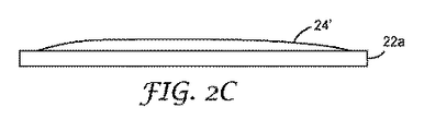
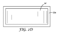
図2Cを参照すると、被覆された粘弾性接着剤のパッチ24’をその主表面の1つに配置させた、基材材料シート22aの部分断面図が図示されている。この図面では、パッチ24’が意図的に不均一な側面プロファイルで厚さを有する。図1の装置は、第1に徐々にポンプ速度を上げていき、基材をピークまでゆるやかなカーブで上がっていくように移動させながら徐々に第1の加熱したコーティングヘッド70を引いていき、徐々にポンプ速度を減らし、基材を移動させながら加熱したコーティングヘッド70を前進させることによってそのようなパッチを製造することができる。当業者は、プロファイルが装置50のバンド幅の範囲内であり、なおかつ粘弾性接着剤組成物の粘度限定の範囲内である限り、コントローラ60が、十分に詳細なプログラミングにより、様々な最終用途に対して多くのプロファイルを生じ得ることを理解するであろう。(組成物は、明確な平衡粘度を有し、極めて小さな外観形状を採用することは期待し得ない)。図2Dは、図2Cの被覆シートの平面図である。パッチは、いくつかの目的についてはできる限り直線で構成されていることが望ましいが、本開示の技術は、別の目的に有用なプロファイルをもったパッチを生成するためにも使用され得る。とりわけ、プロファイルパッチ24’は、硬質カバー層の積層を容易にすることができる。
Referring to FIG. 2C, there is illustrated a partial cross-sectional view of a
図2Eを参照すると、粘弾性接着剤組成物のパッチ24’’をその主表面の1つに配置させた、基材材料シート22aの部分断面図が図示されている。このパッチ24’’では、粘弾性接着剤組成物が意図的に不均一な側面プロファイルで厚さを有する。図2Fは、図2Eの被覆シートの平面図である。この図面では、長手方向のストライプ180は、スロットダイのスロットにおいて非常に幅広いスポットを有するように生成された一方、横方向のストライプ182は、基材22aが動いている際の適切なタイミングに、基材22aから離れる方向にスロットを短時間移動することによって生成され得る。この離れる方向に短時間移動する間、ポンプ速度は、適切に増加し、必要な余剰量の粘弾性接着剤組成物を供給する。
Referring to FIG. 2E, a partial cross-sectional view of a
図2Gを参照すると、粘弾性接着剤組成物のパッチ24’’’をその主表面の1つに配置させた、基材材料シート22aの部分断面図が図示されている。パッチ24’’’では、粘弾性接着剤組成物が意図的に不均一な側面プロファイルで厚さを有する。この図では、一連の長手方向のリブ200は、スロットダイのスロット中に一連の非常に幅広のスポットを有することで生成されている。これは、ノッチスロット又はノッチダイとも呼称され得る。同様の表面構造を実現する代替的手法としては、直線的なスロットダイによって形成されるパッチをコート後にコンタクトツールに接触させるというものがあるだろう。例えば、ワイヤー状に曲がったロッドをコーティング上で手動で引っ張ることでリブ構造を形成できる。
Referring to FIG. 2G, a partial cross-sectional view of a
図2Hを参照すると、長手方向のリブ200に加えて、横方向のストライプ202が、基材22aが動いている際の適切なタイミングに、基材22aから離れる方向にスロットを短時間移動することによって形成されている点を除いて、図2Gと同様の被覆シートの平面図である。図2Fに関連して上述したのと同様に、この離れる方向に短時間移動する間、ポンプ速度は、適切に増加し、必要な余剰量の粘弾性接着剤組成物を供給する。
Referring to FIG. 2H, in addition to the
以上の実施形態のいずれにおいても、パッチは、基材の第1主面の一部のみを被覆し得る。いくつかの実施形態では、外周は、四角形、長方形又は平行四辺形から選択される幾何学的図形を呈している。ある実施形態では、所定の位置は、パッチの周辺部の中心が、基材の主表面の中心に近接するようにして選択されている。 In any of the above embodiments, the patch can cover only a part of the first main surface of the substrate. In some embodiments, the perimeter exhibits a geometric shape selected from a quadrilateral, a rectangle, or a parallelogram. In some embodiments, the predetermined location is selected such that the center of the periphery of the patch is close to the center of the major surface of the substrate.
更なる実施形態では、パッチの厚さは不均一である。いくつかの実施形態では、パッチの厚さは、パッチの中心に近づくほど厚くなり、パッチの厚さは、パッチの周辺部に近づくほど薄くなる。ある実施形態では、パッチは、基材の主表面から外側に延びる少なくとも1つの隆起した個別の突出部が含まれる。いくつかの実施形態では、少なくとも1つの隆起した個別の突出部は、基材の主表面の少なくとも一部を横切って延びる少なくとも1つの隆起したリブからなる。いくつかの実施形態では、少なくとも1つの隆起したリブは、基材の主表面上に横方向に配置された少なくとも2つの隆起したリブを含む。いくつかの実施形態では、少なくとも2つのリブは、パッチの周辺部の中心に近接して交差し重なり合う。 In a further embodiment, the patch thickness is non-uniform. In some embodiments, the patch thickness increases as it approaches the center of the patch, and the patch thickness decreases as it approaches the periphery of the patch. In certain embodiments, the patch includes at least one raised individual protrusion that extends outwardly from the major surface of the substrate. In some embodiments, the at least one raised individual protrusion comprises at least one raised rib that extends across at least a portion of the major surface of the substrate. In some embodiments, the at least one raised rib includes at least two raised ribs disposed laterally on the major surface of the substrate. In some embodiments, the at least two ribs intersect and overlap proximate to the center of the periphery of the patch.
別の実施形態では、少なくとも1つの隆起した個別の突出部は、多数の隆起した個別の突出部である。いくつかの実施形態では、多数の隆起した個別の突出部は、複数の隆起した個別のバンプ、多数の隆起した個別のリブ、又はこれらの組み合わせから選択される。いくつかの実施形態では、多数の隆起した個別のバンプは、半球形のバンプからなる。任意に、多数の隆起した個別のバンプは、整列したパターンで配置される。いくつかの実施形態では、多数の隆起した個別のリブは、犬に与える骨のような形状パターンを形成している。別の実施形態では、多数の隆起した個別のリブは、楕円形のリブからなる。いくつかの実施形態では、多数の隆起した個別のリブは、各リブが隣接するリブと実質的に平行に配置されるように配置される。いくつかの実施形態では、多数の隆起した個別のリブのうち少なくとも2つは、互いに実質的に平行に配置され、多数の隆起した個別のリブのうちの少なくとも1つは、前述の実質的に平行な、少なくとも2つの隆起した個別のリブに対して、実質的に直交配置されている。 In another embodiment, the at least one raised individual protrusion is a number of raised individual protrusions. In some embodiments, the multiple raised individual protrusions are selected from multiple raised individual bumps, multiple raised individual ribs, or combinations thereof. In some embodiments, the multiple raised individual bumps comprise hemispherical bumps. Optionally, a number of raised individual bumps are arranged in an aligned pattern. In some embodiments, the multiple raised individual ribs form a bone-like shape pattern for the dog. In another embodiment, the multiple raised individual ribs consist of elliptical ribs. In some embodiments, the multiple raised individual ribs are arranged such that each rib is arranged substantially parallel to the adjacent rib. In some embodiments, at least two of the plurality of raised individual ribs are disposed substantially parallel to each other, and at least one of the plurality of raised individual ribs is substantially as described above. It is arranged substantially orthogonal to at least two raised individual ribs in parallel.
上記2段落で記載した実施形態に代替する実施形態では、パッチの厚さは、実質的に均一である。1つの実施形態では、パッチの平均厚さは、約1μm〜約500μmの範囲である。いくつかの実施形態では、パッチの厚さは、平均厚さの約+/−10%かそれより良好な均一性を有する。 In an alternative to the embodiment described in the above two paragraphs, the patch thickness is substantially uniform. In one embodiment, the average thickness of the patch ranges from about 1 μm to about 500 μm. In some embodiments, the patch thickness has a uniformity of about +/− 10% or better than the average thickness.
更なる実施形態では、パッチの周辺部は、パッチの複数の外側縁によって画定されている。いくつかの実施形態では、パッチの少なくとも1つの外側縁は、ターゲット位置の約+/−500μm以内で基材の端に対して位置づけられている。 In a further embodiment, the periphery of the patch is defined by a plurality of outer edges of the patch. In some embodiments, at least one outer edge of the patch is positioned relative to the edge of the substrate within about +/− 500 μm of the target location.
積層プロセス
プロセスはまた、パッチが第1の基材と第2の基材の間に位置づけられるように第1の基材に対して第2の基材を配置することを含む積層ステップを含み得、パッチは、第1の基材と第2の基材の各々の少なくとも一部に接触しており、それにより、積層体を形成する。一実施形態では、積層プロセスは、真空又はリブ構造のようなパッチに組み込まれた空気抜き機構によってアシストされ得る。積層プロセスは、ディスプレイパネルなどの光学アセンブリを作るために有利に使用され得る。
Lamination process The process can also include a lamination step that includes positioning the second substrate relative to the first substrate such that the patch is positioned between the first substrate and the second substrate. The patch is in contact with at least a portion of each of the first substrate and the second substrate, thereby forming a laminate. In one embodiment, the lamination process can be assisted by a venting mechanism built into the patch, such as a vacuum or rib structure. The lamination process can be advantageously used to make optical assemblies such as display panels.
光学材料は、光学アセンブリの光学構成要素間又は光学基材間のギャップを充填するのに使用される場合がある。一実施形態では、光学基材に結合されたディスプレイパネルを含む光学アセンブリは、2つのものの間のギャップが、パネル及び基材の屈折率に適合する又はほぼ適合する光学材料で充填された場合、利益を得る場合がある。例えば、ディスプレイパネルと外側カバーシートとの間に固有の、日光及び環境光の反射は低減される場合がある。別の実施形態では、光学材料は、パネル及び基材のうちの少なくとも1つの屈折率と異なる屈折率を有し得る。ディスプレイパネルの色域及びコントラストは、周囲条件下で改善され得る。充填されたギャップを有する光学アセンブリは、エアギャップを有する同様のアセンブリと比較して、改善された衝撃耐性を呈することもできる。 Optical materials may be used to fill gaps between optical components of an optical assembly or between optical substrates. In one embodiment, an optical assembly that includes a display panel coupled to an optical substrate is filled with an optical material in which the gap between the two matches or nearly matches the refractive index of the panel and substrate. May benefit. For example, the reflection of sunlight and ambient light inherent between the display panel and the outer cover sheet may be reduced. In another embodiment, the optical material may have a refractive index that is different from the refractive index of at least one of the panel and the substrate. The color gamut and contrast of the display panel can be improved under ambient conditions. An optical assembly having a filled gap can also exhibit improved impact resistance compared to a similar assembly having an air gap.
光学アセンブリ
大きな寸法、すなわち面積を有する光学アセンブリは、特に効率及び厳しい光学品質が望まれる場合、製造するのが難しい場合がある。光学構成要素間のギャップは、ギャップ内に硬化性組成物を注ぎ又は注入し、続いて組成物を硬化させて構成要素同士を一緒に結合することによって充填され得る。しかしながら、これらの一般的に使用される組成物は長い流出時間を有し、これは大型の光学アセンブリには非効率的な製造方法の一因となる。
Optical assemblies Optical assemblies having large dimensions, i.e. areas, can be difficult to manufacture, especially when efficiency and stringent optical quality are desired. The gap between the optical components can be filled by pouring or pouring the curable composition into the gap, followed by curing the composition and bonding the components together. However, these commonly used compositions have a long run time, which contributes to an inefficient manufacturing method for large optical assemblies.
本明細書に開示される光学アセンブリは、接着剤層、光学構成要素、特にディスプレイパネル、及び実質的に光透過性の基材を含む。接着剤層のいくつかは、構成要素に損傷をほとんど又は全く与えることなく、アセンブリを再加工することができる一方、他の接着剤層は、より永久的な結合を生じ得る。再加工可能な接着剤層は、約15N/mm以下、10N/mm以下、又は6N/mm以下のガラス基材間の割裂接着強さを有してもよく、これによって、構成要素に損傷をほとんど与えず、又は全く与えずに再加工性を得ることができる。割裂に対する合計エネルギーは、1インチ*1インチ(2.54cm*2.54cm)の面積にわたって約25kg*mm未満であり得る。 The optical assemblies disclosed herein include an adhesive layer, optical components, particularly a display panel, and a substantially light transmissive substrate. Some of the adhesive layers can rework the assembly with little or no damage to the components, while other adhesive layers can result in a more permanent bond. The reworkable adhesive layer may have a split adhesion strength between glass substrates of about 15 N / mm or less, 10 N / mm or less, or 6 N / mm or less, thereby damaging the components. Reworkability can be obtained with little or no application. The total energy for the split may be less than about 25 kg * mm over an area of 1 inch * 1 inch (2.54 cm * 2.54 cm).
実質的に透明な基材
光学アセンブリに使用される実質的に透明な基材は、様々なタイプの材料を含み得る。実質的に透明な基材は、光学用途に適しており、典型的には400〜720nmの範囲にわたる可視光の少なくとも85%の透過率を有する。実質的に透明な基材は、厚さ1ミリメートル当たり、400nmで約85%超の透過率、530nmで約90%超の透過率、及び670nmで約90%超の透過率を有することができる。
Substantially Transparent Substrate Substantially transparent substrates used in optical assemblies can include various types of materials. Substantially transparent substrates are suitable for optical applications and typically have a transmission of at least 85% of visible light over a range of 400-720 nm. The substantially transparent substrate can have a transmission greater than about 85% at 400 nm per millimeter of thickness, a transmission greater than about 90% at 530 nm, and a transmission greater than about 90% at 670 nm. .
実質的に透明な基材は、ガラス又はポリマーを含み得る。有用なガラスには、ホウケイ酸、ソーダ石灰、及び保護カバーとしてディスプレイ用途での使用に適した他のガラスを挙げることができる。使用され得る1つの具体的なガラスは、Corning Inc.から入手可能なEAGLE XG及びJADEガラス基材である。有用なポリマーは、ポリエチレンテレフタレート(polyethylene terephalate)などのポリエステルフィルム、ポリカーボネートフィルム若しくはプレート、ポリメチルメタクリレートフィルムなどのアクリルフィルム、並びに、Zeon Chemicals L.P.から入手可能なZEONOX及びZEONORなどのシクロオレフィンポリマーフィルムが挙げられる。実質的に透明な基材は、任意に約1.4〜約1.7の屈折率を有する。実質的に透明な基材は、典型的には、約0.5〜約5mmの厚さを有する。ディスプレイスタックで使用されるその他のフィルムには、吸収型偏光子又は円偏光子、四分の一波長板、OLEDsで使用されるようなバリアフィルム、輝度増強フィルム等を含む。 The substantially transparent substrate can comprise glass or a polymer. Useful glasses can include borosilicate, soda lime, and other glasses suitable for use in display applications as protective covers. One specific glass that can be used is Corning Inc. EAGLE XG and JADE glass substrates available from Useful polymers include polyester films such as polyethylene terephthalate, polycarbonate films or plates, acrylic films such as polymethyl methacrylate film, and Zeon Chemicals L.A. P. And cycloolefin polymer films such as ZEONOX and ZEONOR available from The substantially transparent substrate optionally has a refractive index of about 1.4 to about 1.7. The substantially transparent substrate typically has a thickness of about 0.5 to about 5 mm. Other films used in display stacks include absorptive or circular polarizers, quarter wave plates, barrier films as used in OLEDs, brightness enhancement films, and the like.
実質的に透明な基材は、タッチスクリーンを含み得る。タッチスクリーンは周知であり、通常、2つの実質的に透明な基材間に配置された透明な導電層を含む。 The substantially transparent substrate can include a touch screen. Touch screens are well known and typically include a transparent conductive layer disposed between two substantially transparent substrates.
いくつかの実施形態において、実質的に透明な基材は、インクステップを含み得る。本発明の粘弾性組成物及びプロセスを使用すると、均一な被覆とインクステップの平準化とが可能になる。 In some embodiments, the substantially transparent substrate can include an ink step. The viscoelastic composition and process of the present invention allows for uniform coating and ink step leveling.
接着剤層
粘弾性接着剤組成物は、光学用途に適したものであり得る層を形成する。例えば、粘弾性接着剤層は、400〜720nmの範囲にわたって少なくとも85%の透過率を有し得る。例えば、接着剤層は、厚さ1ミリメートル当たり、400nmで約85%より大きい透過率、530nmで約90%より大きい透過率、及び670nmで約90%より大きい透過率を有することができる。これらの透過特性により、電磁スペクトルの可視領域全体にわたって均一な光透過率がもたらされ、これは、フルカラーディスプレイで色点を維持するのに重要である。
Adhesive Layer The viscoelastic adhesive composition forms a layer that may be suitable for optical applications. For example, the viscoelastic adhesive layer may have a transmittance of at least 85% over a range of 400-720 nm. For example, the adhesive layer can have a transmission greater than about 85% at 400 nm per millimeter of thickness, a transmission greater than about 90% at 530 nm, and a transmission greater than about 90% at 670 nm. These transmission characteristics provide uniform light transmission throughout the visible region of the electromagnetic spectrum, which is important for maintaining the color point in a full color display.
接着剤層の透明特性のヘイズ部分は、Byk Gardnerから入手可能なHazeGard Plus又はHunter Labsから入手可能なUltraScan Proなどのヘイズメーターによって測定されるように、接着剤層の%ヘイズ価によって更に定義される。光学的に透明な物品は、好ましくは、約5%未満、好ましくは約2%未満、最も好ましくは約1%未満のヘイズを有する。これらのヘイズ特性は、低い光散乱を提供し、これはフルカラーディスプレイで出力の質を維持するのに重要である。 The haze portion of the transparency properties of the adhesive layer is further defined by the% haze number of the adhesive layer as measured by a haze meter such as HazeGard Plus available from Byk Gardner or UltraScan Pro available from Hunter Labs. The The optically clear article preferably has a haze of less than about 5%, preferably less than about 2%, and most preferably less than about 1%. These haze characteristics provide low light scattering, which is important for maintaining output quality in full color displays.
接着剤の屈折率は、適切な接着剤成分を選択することによって制御することができる。例えば屈折率は、より高い含有率の芳香族構造を含む、又は硫黄若しくはハロゲン(例えば臭素)を組み込むオリゴマー、及び希釈モノマー等を組み込むことによって増加させることができる。反対に屈折率は、より高含有率で脂肪族構造を含有するポリマー、オリゴマー、及び希釈モノマー等を組み込むことによって、より低い値へと調節することができる。例えば接着剤層は約1.4〜約1.7の屈折率を有し得る。 The refractive index of the adhesive can be controlled by selecting an appropriate adhesive component. For example, the refractive index can be increased by incorporating higher content aromatic structures or incorporating oligomers that incorporate sulfur or halogens (eg, bromine), diluent monomers, and the like. Conversely, the refractive index can be adjusted to a lower value by incorporating polymers, oligomers, diluting monomers, etc. with higher content and containing aliphatic structures. For example, the adhesive layer can have a refractive index of about 1.4 to about 1.7.
粘弾性接着剤層は、ポリマー、オリゴマー、希釈モノマー、充填剤、可塑剤、粘着付与樹脂、光開始剤、及び接着剤の全体の特性に寄与する任意の他の成分を含む適切な接着剤成分を選択することによって透明性を保つことができる。具体的には、粘弾性接着剤成分は互いに適合性を有するべきであり、例えば、拡散接着剤用途など、ヘイズが望ましい結果である場合を除き、ドメインサイズ及び屈折率差が光散乱及びヘイズを生じさせる点まで硬化する前又は硬化した後に、それらは相分離すべきではない。更に、粘弾性接着剤成分には、接着剤配合物内に溶解せず、かつ光を散乱させるのに十分大きく、したがって、ヘイズに寄与する粒子が含まれない。拡散接着剤用途など、ヘイズが望ましい場合、これは容認可能である。更に、チキソトロピック材料などの様々な充填剤は、それらが光透過の損失及びヘイズの増加に寄与し得る相分離又は光散乱に寄与しないように、非常に良く分散されるべきである。この場合もやはり、拡散接着剤用途など、ヘイズが望ましい場合は、これは容認可能である。これらの粘弾性接着剤成分はまた、例えば接着剤層に色を付与すること、又は接着剤層のb*、すなわち黄色度指数を増加させることによって、透明度に関する色特性を低下させるべきではない。 The viscoelastic adhesive layer is a suitable adhesive component that includes polymers, oligomers, diluent monomers, fillers, plasticizers, tackifier resins, photoinitiators, and any other components that contribute to the overall properties of the adhesive. Transparency can be maintained by selecting. Specifically, the viscoelastic adhesive components should be compatible with each other, for example, domain size and refractive index differences may cause light scattering and haze unless the haze is a desired result, such as in diffusion adhesive applications. They should not phase separate before or after curing to the point of formation. In addition, the viscoelastic adhesive component does not include particles that do not dissolve in the adhesive formulation and are large enough to scatter light and thus contribute to haze. If haze is desired, such as in diffusion adhesive applications, this is acceptable. Furthermore, various fillers such as thixotropic materials should be very well dispersed so that they do not contribute to phase separation or light scattering which can contribute to loss of light transmission and increased haze. Again, this is acceptable if haze is desired, such as in diffusion adhesive applications. These viscoelastic adhesive components should also not degrade the color characteristics with respect to transparency, for example by imparting color to the adhesive layer or by increasing the b * of the adhesive layer, ie the yellowness index.
接着剤層は、ディスプレイパネルと、実質的に透明な基材と、ディスプレイパネルと実質的に透明な基材との間に配置された接着剤層と、を含む、光学アセンブリに使用され得る。 The adhesive layer can be used in an optical assembly that includes a display panel, a substantially transparent substrate, and an adhesive layer disposed between the display panel and the substantially transparent substrate.
粘弾性接着剤層は任意の厚さを有し得る。光学アセンブリで採用される具体的な厚さは、任意の数の因子から求めることができ、例えば、光学アセンブリを使用する光学デバイスの設計では、ディスプレイパネルと実質的に透明な基材との間にある程度のギャップを必要とすることがある。粘弾性接着剤層は、典型的には、約1μm〜約5mm、約50μm〜約1mm、又は約50μm〜約0.3mmの厚さを有する。 The viscoelastic adhesive layer can have any thickness. The specific thickness employed in the optical assembly can be determined from any number of factors, for example, in the design of an optical device using the optical assembly, between the display panel and the substantially transparent substrate. Some gaps may be required. The viscoelastic adhesive layer typically has a thickness of about 1 μm to about 5 mm, about 50 μm to about 1 mm, or about 50 μm to about 0.3 mm.
硬化
プロセスは、更に、熱、化学線、電離放射線又はこれらの組み合わせを適用することにより、粘弾性接着剤組成物を硬化させることを含み得る。
The curing process can further include curing the viscoelastic adhesive composition by applying heat, actinic radiation, ionizing radiation, or a combination thereof.
任意の形態の電磁放射線が使用されてもよく、例えば粘弾性接着剤組成物は、紫外線照射及び/又は熱を使用して硬化されてもよい。電子ビーム線もまた使用し得る。上記の粘弾性接着剤組成物は、化学線、すなわち光化学的活性の生成につながる放射線を使用して硬化されると言われる。例えば、化学線は約250〜約700nmの放射線を含み得る。化学線の供給源としては、タングステンハロゲンランプ、キセノン及び水銀アークランプ、白熱灯、殺菌灯、蛍光ランプ、レーザ、及び発光ダイオードが挙げられる。紫外線は、Fusion UV Systemsから入手可能なもののように、高強度の連続的照射システムを使用して供給することができる。紫外線照射は、断続的なものであっても脈動的なものであってもよい。 Any form of electromagnetic radiation may be used, for example the viscoelastic adhesive composition may be cured using ultraviolet radiation and / or heat. Electron beam radiation can also be used. The viscoelastic adhesive composition described above is said to be cured using actinic radiation, ie radiation that results in the generation of photochemical activity. For example, actinic radiation can include about 250 to about 700 nm of radiation. Sources of actinic radiation include tungsten halogen lamps, xenon and mercury arc lamps, incandescent lamps, germicidal lamps, fluorescent lamps, lasers, and light emitting diodes. Ultraviolet light can be delivered using a high intensity continuous illumination system, such as that available from Fusion UV Systems. The ultraviolet irradiation may be intermittent or pulsating.
いくつかの実施形態では、化学線は、粘弾性接着剤組成物が部分的に重合又は架橋されるように、当該組成物の層に適用され得る。粘弾性接着剤組成物は、ディスプレイパネルと実質的に透明な基材との間に配置されて、次いで部分的に重合又は架橋され得る。粘弾性接着剤組成物は、ディスプレイパネル又は実質的に透明な基材上に配置されて、部分的に重合されてもよく、次いでディスプレイパネル及び基材の他方は部分的に重合又は架橋された層の上に配置され得る。 In some embodiments, actinic radiation can be applied to a layer of the composition such that the viscoelastic adhesive composition is partially polymerized or crosslinked. The viscoelastic adhesive composition can be placed between the display panel and the substantially transparent substrate and then partially polymerized or crosslinked. The viscoelastic adhesive composition may be placed on a display panel or a substantially transparent substrate and partially polymerized, and then the other of the display panel and substrate is partially polymerized or crosslinked It can be placed on the layer.
いくつかの実施形態では、化学線は、粘弾性接着剤組成物が完全に、又はほぼ完全に重合若しくは架橋されるように、当該組成物の層に適用され得る。一実施形態では、粘弾性接着剤組成物は、ディスプレイパネルと実質的に透明な基材との間に配置され、次いで完全に、又はほぼ完全に重合又は架橋されてもよい。別の実施形態では、粘弾性接着剤組成物は、ディスプレイパネル又は実質的に透明な基材上に配置されて、完全に又はほぼ完全に重合又は架橋され、次いでもう一方のディスプレイパネル及び基材は重合又は架橋された層の上に配置されてもよい。 In some embodiments, actinic radiation can be applied to the layers of the composition such that the viscoelastic adhesive composition is completely or nearly completely polymerized or crosslinked. In one embodiment, the viscoelastic adhesive composition may be disposed between the display panel and the substantially transparent substrate and then fully or almost completely polymerized or crosslinked. In another embodiment, the viscoelastic adhesive composition is disposed on a display panel or a substantially transparent substrate and is completely or almost completely polymerized or crosslinked, and then the other display panel and substrate. May be disposed on the polymerized or crosslinked layer.
アセンブリプロセスにおいて、実質的に均一な粘弾性接着剤組成物の層を有することが一般的に望ましい。次いで照射を適用し、粘弾性接着剤層を形成してもよい。 It is generally desirable to have a layer of a substantially uniform viscoelastic adhesive composition in the assembly process. Irradiation may then be applied to form a viscoelastic adhesive layer.
ディスプレイパネル
いくつかの特殊な実施形態では、積層体は、有機発光ダイオードディスプレイ、有機発光トランジスタディスプレイ、液晶ディスプレイ、プラズマディスプレイ、表面電界ディスプレイ、電界放出ディスプレイ、量子ドットディスプレイ、液晶ディスプレイ、微小電気機械システムディスプレイ、強誘電性液晶ディスプレイ、厚膜誘電電子発光ディスプレイ、伸縮ピクセルディスプレイ又はレーザ蛍光ディスプレイから選択されるディスプレイパネルからなる。
Display Panel In some special embodiments, the laminate is an organic light emitting diode display, organic light emitting transistor display, liquid crystal display, plasma display, surface field display, field emission display, quantum dot display, liquid crystal display, microelectromechanical system The display panel is selected from a display, a ferroelectric liquid crystal display, a thick film dielectric electroluminescent display, a stretchable pixel display or a laser fluorescent display.
ディスプレイパネルは、液晶ディスプレイパネルなど任意のタイプのパネルを含み得る。液晶ディスプレイパネルは周知であり、典型的にはガラス基材又はポリマー基材などの2つの実質的に透明な基材間に配置された、液晶材料を含む。実質的に透明な基材の内表面には、電極として機能する透明な導電性材料がある。場合によっては、実質的に透明な基材の外表面には、本質的に、ただ1つの偏光状態の光だけを通す偏光フィルムがある。電圧が電極に対して選択的に印加されると、液晶材料は再配向して光の偏光状態を変え、それにより、画像が形成される。液晶ディスプレイパネルはまた、マトリクスパターンで配置された複数の薄膜トランジスタを有する薄膜トランジスタアレイパネルと、共通電極を有する共通電極パネルとの間に配置された液晶材料を含み得る。 The display panel may include any type of panel such as a liquid crystal display panel. Liquid crystal display panels are well known and typically include a liquid crystal material disposed between two substantially transparent substrates, such as a glass substrate or a polymer substrate. On the inner surface of the substantially transparent substrate, there is a transparent conductive material that functions as an electrode. In some cases, the outer surface of the substantially transparent substrate has a polarizing film that essentially passes only light in one polarization state. When voltage is selectively applied to the electrodes, the liquid crystal material reorients and changes the polarization state of the light, thereby forming an image. The liquid crystal display panel may also include a liquid crystal material disposed between a thin film transistor array panel having a plurality of thin film transistors arranged in a matrix pattern and a common electrode panel having a common electrode.
ディスプレイパネルは、プラズマディスプレイパネルを含み得る。プラズマディスプレイパネルは周知であり、典型的には2つのガラスパネル間に位置する小セル内に配置されたネオン及びキセノンなどの希ガスからなる不活性混合物を含む。制御回路は、パネル内の電極を帯電させて、これがガスをイオン化し、プラズマを形成するようにし、次いで、プラズマが蛍光体を励起して発光させる。 The display panel can include a plasma display panel. Plasma display panels are well known and typically include an inert mixture of noble gases such as neon and xenon disposed in a small cell located between two glass panels. The control circuit charges the electrodes in the panel so that it ionizes the gas and forms a plasma, which then excites the phosphor to emit light.
ディスプレイパネルは、有機エレクトロルミネッセンスパネルを含み得る。これらのパネルは本質的に2つのガラスパネル間に配置された有機材料の1つの層である。有機材料は、有機発光ダイオード(OLED)又は高分子発光ダイオード(PLED)を含み得る。これらのパネルは周知である。 The display panel can include an organic electroluminescent panel. These panels are essentially one layer of organic material placed between two glass panels. The organic material can include an organic light emitting diode (OLED) or a polymer light emitting diode (PLED). These panels are well known.
ディスプレイパネルは、電気泳動ディスプレイを含み得る。電気泳動ディスプレイは既知であり、典型的には、電子ペーパー、すなわちe−ペーパーと呼ばれるディスプレイ技術に使用される。電気泳動ディスプレイは、2つの透明電極パネル間に配置された液状の帯電物質を含む。液状の帯電材料は、非極性炭化水素中に懸濁されたナノ粒子、染料及び帯電剤、又は炭化水素材料中に懸濁された、帯電した粒子を充填されたマイクロカプセルを含み得る。マイクロカプセルはまた、液体ポリマーの層に懸濁されてもよい。 The display panel can include an electrophoretic display. Electrophoretic displays are known and are typically used in a display technology called electronic paper, or e-paper. The electrophoretic display includes a liquid charged substance disposed between two transparent electrode panels. Liquid charged materials may include nanoparticles, dyes and charging agents suspended in nonpolar hydrocarbons, or microcapsules filled with charged particles suspended in a hydrocarbon material. The microcapsules may also be suspended in a layer of liquid polymer.
ディスプレイパネルは、エレクトロウェッティング方式のディスプレイを含み得る。 The display panel may include an electrowetting display.
本明細書に開示した光学アセンブリ及び/又はディスプレイパネルは、特に限定されないが、例えば、電話などの携帯デバイス、テレビ、コンピュータモニタ、プロジェクタ、自動車用ディスプレイ、タブレット又は表示板を含む様々な光学デバイスに使用することができる。光学デバイスは、バックライト又は自発光を含んでよい。 The optical assemblies and / or display panels disclosed herein are not particularly limited, but include various optical devices including, for example, portable devices such as telephones, televisions, computer monitors, projectors, automotive displays, tablets, or display boards. Can be used. The optical device may include a backlight or self light emission.
これらの実施例は単にあくまで例示を目的としたものであり、添付した特許請求の範囲に過度に限定することを意味するものではない。本開示の広い範囲を記載する数値範囲及びパラメータは、近似値ではあるが、特定の実施例で記載される数値は、可能な限り正確に報告される。しかしながら、いずれの数値も、元来、それらの各試験測定値内に見出される標準偏差から必然的に生じる、特定の誤差を含む。少なくとも、また特許請求の範囲への均等論の適用を制限しようとするものではないが、各数値パラメータは少なくとも、報告された有効数字の桁数を考慮し、通常の端数処理法を適用することによって、解釈されるべきである。

試験方法
固体分試験法
2つずつ作製した試料を、予め計量したアルミパンに載せて、次に105℃で最低3時間(又は代替的に160℃で45分間真空乾燥)乾燥させた。ポリマー固体分は、湿潤重量に対して重量測定法で分析した2つの試料の平均とした。
Test Method Solids Test Method Two samples prepared were placed on a pre-weighed aluminum pan and then dried at 105 ° C for a minimum of 3 hours (or alternatively vacuum dried at 160 ° C for 45 minutes). Polymer solids were the average of two samples analyzed gravimetrically relative to wet weight.
分子量分布の決定
化合物の分子量分布は、従来のゲル透過クロマトグラフィー(GPC)を用いて特性評価した。Waters Corporation(Milford,MA,USA)から入手したGPC装置は、高圧液体クロマトグラフィーポンプ(モデル1515HPLC)、オートサンプラー(モデル717)、UV検出機(モデル2487)、及び屈折率検出機(モデル2410)を備えていた。クロマトグラフは、2つの5ミクロンのPLgel MIXED−Dカラム(Varian Inc.(Palo Alto,CA,USA)から入手可能)を備えていた。
Determination of molecular weight distribution The molecular weight distribution of the compounds was characterized using conventional gel permeation chromatography (GPC). GPC equipment obtained from Waters Corporation (Milford, MA, USA) includes a high pressure liquid chromatography pump (model 1515 HPLC), an autosampler (model 717), a UV detector (model 2487), and a refractive index detector (model 2410). It was equipped with. The chromatograph was equipped with two 5 micron PLgel MIXED-D columns (available from Varian Inc. (Palo Alto, Calif., USA)).
ポリマー又は乾燥ポリマー材料を0.5%(重量/体積)の濃度でテトラヒドロフランに溶解し、VWR International(West Chester,PA,USA)から入手可能である0.2ミクロンのポリテトラフルオロエチレンフィルターを通して濾過することにより、ポリマー溶液のサンプルを調製した。得られたサンプルをGPCに注入し、35℃で維持されたカラムを通して毎分1ミリリットルの速度で溶出させた。このシステムを、線形最小二乗法適合分析を用いてポリスチレン標準で較正して、検量線を作製した。重量平均分子量(Mw)及び多分散指数(重量平均分子量を数平均分子量で除算したもの)をこの標準検量線に対して各サンプルについて計算した。 Polymer or dry polymer material is dissolved in tetrahydrofuran at a concentration of 0.5% (w / v) and filtered through a 0.2 micron polytetrafluoroethylene filter available from VWR International (West Chester, PA, USA). A sample of the polymer solution was prepared. The resulting sample was injected into the GPC and eluted at a rate of 1 milliliter per minute through a column maintained at 35 ° C. The system was calibrated with polystyrene standards using linear least squares fit analysis to generate a calibration curve. The weight average molecular weight (M w ) and polydispersity index (weight average molecular weight divided by number average molecular weight) were calculated for each sample against this standard calibration curve.
アクリル系ポリマー合成
実施例1
65.12gの2−EHA、20.0gのBA、7.0gのAcm、7.0gのn−プロパノール、3.0gのHPA、0.10gのIRGANOX 1010抗酸化剤、4.00gの10.0重量%tDDM(連鎖移動剤)含有2−EHA溶液及び0.82gの2.44重量%MEHQ含有2−EHA溶液を8オンスガラス瓶内で攪拌して、60℃に加熱することで溶液を調製した。溶液は45℃に冷却した。固体分0.25重量%のVAZO 52の2−EHA中混合物0.48gを添加し、混合した。上記混合物のうち80gをステンレススチール反応器(Fauske and Associated Inc.(Burr Ridge,IL)から入手可能な316ステンレススチール缶を備えたVSP2断熱反応容器)に移した。反応器には、加熱しながら酸素をパージし、61℃の誘導温度に達する前に、60psiの窒素ガスで加圧した。重合反応は断熱条件下で進行し、反応温度のピークは130℃に達した。これは表3で反応温度のピーク1として報告している。反応混合物から5.0gを分取したところ、未反応のモノマー/溶媒は、混合物の総重量に対して55.95重量%であった。これは表3で揮発分割合1として報告している。
Acrylic polymer synthesis Example 1
65.12 g 2-EHA, 20.0 g BA, 7.0 g Acm, 7.0 g n-propanol, 3.0 g HPA, 0.10 g IRGANOX 1010 antioxidant, 4.00
4オンスガラス瓶中で、1.0gのVAZO 52開始剤、0.10gのVAZO 88開始剤、0.05gのLUPERSOL 101過酸化物、0.15gのLUPERSOL 130過酸化物、48.70gの酢酸エチルを混合することにより溶液を調製した。この混合物を往復ミキサーで振盪して固形物を溶解した。その後、この溶液0.7gと0.35gの10.0重量%tDDM(連鎖移動剤)含有2−EHA溶液とをステンレススチール反応器中で撹拌した。反応器には、加熱しながら酸素をパージし、59℃の誘導温度に達する前に、60ポンド/平方インチ(psi)の窒素ガスで加圧した。重合反応は断熱条件下で進行し、反応温度のピークは145℃に達した。これは表3で反応温度のピーク2として報告している。混合物をこの温度で60分間等温保持した後、8オンス瓶に流した。サンプルを取り出したところ、未反応のモノマー/溶媒は、混合物の総重量に対して9.70重量%であった。これは表3で揮発分割合2として報告している。
In a 4 oz glass bottle, 1.0
実施例2
54.30gの2−EHA、30.0gのBA、7.0gのAcm、3.0gのHPA、0.10gのIRGANOX 1010抗酸化剤、5.00gの10.0重量%tDDM(連鎖移動剤)含有2−EHA溶液及び0.82gの2.44重量%MEHQ含有2−EHA溶液を8オンスガラス瓶内で攪拌して60℃に加熱することで溶液を調製した。溶液は45℃に冷却した。固体分0.25重量%のVAZO 52の2−EHA中混合物0.40gを添加し、混合した。その後、混合物80gを実施例1に記載のステンレススチール反応器に移した。反応器には、加熱しながら酸素をパージし、61℃の誘導温度に達する前に、60psiの窒素ガスで加圧した。重合反応は断熱条件下で進行し、反応温度のピークは132℃に達した。これは表3で反応温度のピーク1として報告している。反応混合物から5.0gを分取したところ、未反応のモノマー/溶媒は、混合物の総重量に対して55.26重量%であった。これは表3で揮発分割合1として報告している。
Example 2
54.30 g 2-EHA, 30.0 g BA, 7.0 g Acm, 3.0 g HPA, 0.10 g IRGANOX 1010 antioxidant, 5.00 g 10.0 wt% tDDM (chain transfer agent ) Containing 2-EHA solution and 0.82 g of 2.44-wt% MEHQ-containing 2-EHA solution were stirred in an 8 ounce glass bottle and heated to 60 ° C. to prepare a solution. The solution was cooled to 45 ° C. 0.40 g of a mixture of 0.25 wt
4オンスガラス瓶中で、1.0gのVAZO 52開始剤、0.10gのVAZO 88開始剤、0.05gのLUPERSOL 101過酸化物、0.15gのLUPERSOL 130過酸化物、48.70gの酢酸エチルを混合することにより溶液を調製した。この混合物を往復ミキサーで振盪して固形物を溶解した。その後、溶液0.7gをステンレススチール反応器で攪拌した。反応器には、加熱しながら酸素をパージし、59℃の誘導温度に達する前に、60ポンド/平方インチ(psi)の窒素ガスで加圧した。重合反応は断熱条件下で進行し、反応温度のピークは149℃に達した。これは表3で反応温度のピーク2として報告している。混合物をこの温度で60分間等温保持した後、8オンス瓶に流した。サンプルを取り出したところ、未反応のモノマー/溶媒は、混合物の総重量に対して8.83重量%であった。これは表3で揮発分割合2として報告している。
In a 4 oz glass bottle, 1.0
実施例3
実施例3は、実施例1及び実施例2に記載した手順を用いて、表2に規定した処方に従って合成した。反応温度のピーク及び揮発分割合を表3に示す。
Example 3
Example 3 was synthesized according to the recipe specified in Table 2 using the procedure described in Example 1 and Example 2. Table 3 shows the peak reaction temperature and the volatile fraction.
実施例4
実施例4は、反応器にIEMを真空充填し、内容物を等温条件下で約20分間、約150℃に保持するという追加のステップとともに実施例1及び実施例2に記載の手順を用いて表2の処方に従って合成された。次に0.75pphの光開始剤(IRGACURE−184)を反応器に加えた。反応器を更に30分間攪拌し混合物を取り出した。反応温度のピーク及び揮発分割合を表3に示す。
Example 4 uses the procedure described in Example 1 and Example 2 with the additional step of vacuum filling the reactor with IEM and holding the contents at about 150 ° C. for about 20 minutes under isothermal conditions. Synthesized according to the formulation in Table 2. 0.75 pph photoinitiator (IRGACURE-184) was then added to the reactor. The reactor was stirred for an additional 30 minutes and the mixture was removed. Table 3 shows the peak reaction temperature and the volatile fraction.
ポリアクリル酸粘度測定
粘度は、20mm平行板(TA Instruments社(New Castle,DE)製)を使用してTA Instruments社のDHR−2レオメーターで測定した。溶融粘度は、50℃〜90℃(実施例4は、50℃〜130℃の温度で測定した)の温度で0.1〜100ラジアン/秒の剪断速度でディケイドごとに3点10%ひずみを測定し、データは、20℃の温度間隔で取得した。図3は、実施例1〜4のアクリレートポリマーの複素粘度の剪断速度の関数としてのプロットを示す。
Polyacrylic acid viscosity measurement Viscosity was measured with a TA Instruments DHR-2 rheometer using a 20 mm parallel plate (TA Instruments (New Castle, DE)). The melt viscosity was 3% 10% strain per decade at a shear rate of 0.1 to 100 radians / second at a temperature of 50 ° C. to 90 ° C. (Example 4 was measured at a temperature of 50 ° C. to 130 ° C.). Measurements and data were taken at a temperature interval of 20 ° C. FIG. 3 shows a plot of complex viscosity as a function of shear rate for the acrylate polymers of Examples 1-4.
ポリウレタン合成
調製物A。16当量のIPDI+14当量のFomrez 55−112 1000 MW ポリ(ネオペンチルアジペート)ジオール+2当量のHEAの調製
オーバーヘッドスターラーを備えた2Lの3つ口丸底フラスコに100g(0.449843当量)のIPDIと100gMEKとを充填し、70℃のオイルバスで約10分間加熱した。その後、0.25gのDBTDL(固形分で500ppm)を反応に添加した。反応液を乾燥空気雰囲気下に置き、凝縮器に装着した。次に、等圧ロートを介して、500g(0.393612当量)のFomrez 55−112ジオールの100gのMEK溶液を反応液に2.5時間かけて添加した。ロートは、各回20gMEKで3回すすぎ、反応を48時間継続させた。その後、13.06g(0.112461当量)のヒドロキシエチルアクリレート及び246.7gのMEKを反応液に添加した。約24時間の更なる反応後、反応液にはMEKを添加し固形分50%に調整した。
Polyurethane synthesis Preparation A. Preparation of 16 equivalents of IPDI + 14 equivalents of Fomrez 55-112 1000 MW poly (neopentyl adipate) diol + 2 equivalents of HEA And heated in an oil bath at 70 ° C. for about 10 minutes. Thereafter, 0.25 g DBTDL (500 ppm solids) was added to the reaction. The reaction was placed in a dry air atmosphere and attached to the condenser. Next, 100 g of MEK solution of 500 g (0.393612 equivalent) of Fomrez 55-112 diol was added to the reaction via an isobaric funnel over 2.5 hours. The funnel was rinsed 3 times with 20 g MEK each time and the reaction was allowed to continue for 48 hours. Thereafter, 13.06 g (0.112461 equivalents) of hydroxyethyl acrylate and 246.7 g of MEK were added to the reaction solution. After further reaction for about 24 hours, MEK was added to the reaction solution to adjust the solid content to 50%.
調製物B。70重量部[調製物A]+30重量部CN3100の調製。
オーバーヘッドスターラーと蒸留ヘッドを備えた250mLの3つ口丸底フラスコに59.4g(29.7g固形分)の調製物A、12.72gのCN3100及び20mgのBHTを充填した。100℃のオイルバス中、アスピレーター圧力下で約15分間、次いで約20Torrの機械ポンプ圧力下で15分間加熱し、本質的に溶媒を含まないポリウレタンとCN3100との70:30混合物を調製した。
Preparation B. Preparation of 70 parts by weight [Preparation A] + 30 parts by weight CN3100.
A 250 mL 3-neck round bottom flask equipped with an overhead stirrer and distillation head was charged with 59.4 g (29.7 g solids) of Preparation A, 12.72 g of CN3100 and 20 mg of BHT. A 70:30 mixture of polyurethane and CN3100 essentially free of solvent was prepared by heating in an oil bath at 100 ° C. for about 15 minutes under aspirator pressure and then for 15 minutes under mechanical pump pressure of about 20 Torr.
ポリウレタン粘度測定
粘度は、20mm平行板(TA Instruments社(New Castle,DE)製)を使用してAR−G2レオメーターで測定した。定常剪断粘度は、1.0mmギャップで測定し、蒸発を防ぐため、水トラップを使用した。0.1〜100ラジアン/秒の剪断速度及び20℃温度間隔で10℃〜90℃の温度で粘度を測定した。高剪断速度の平行板の間から溶融物がこぼれたため、定常状態剪断粘度を25℃で測定し、20秒−1に制限した。25℃で0.1〜100/秒の定常状態剪断速度に対する粘度のプロットを図4に示す。
残りの実施例は仮想的なものである。
Measurement of polyurethane viscosity Viscosity was measured with an AR-G2 rheometer using a 20 mm parallel plate (manufactured by TA Instruments (New Castle, DE)). The steady shear viscosity was measured with a 1.0 mm gap and a water trap was used to prevent evaporation. The viscosity was measured at a temperature of 10 ° C. to 90 ° C. with a shear rate of 0.1 to 100 radians / second and a 20 ° C. temperature interval. As the melt spilled from between the high shear rate parallel plates, the steady state shear viscosity was measured at 25 ° C. and limited to 20 sec −1 . A plot of viscosity versus steady state shear rate of 0.1-100 / sec at 25 ° C. is shown in FIG.
The remaining embodiments are virtual.
粘度測定実施例
伸長粘度
HAAKE(商標)CaBER(商標)1 Capillary Breakup伸長レオメーター(Thermo Fisher Scientific,Inc.(Waltham,MA)から入手可能)を光学的に透明な接着剤(OCA)の見かけの伸長粘度の測定に使用する。見かけの伸長粘度は、同じ場所の応力と伸びの比率である。見かけの伸長粘度は、Pa−sの単位で報告する。
Viscosity Measurement Examples Elongation Viscosity HAAKE
ノーマライズした直径を有するOCAサンプルを、CaBER(商標)1伸長レオメーターを用いて、少量のサンプルを直径6mmの2つの円形プレート間に置いて、初期高さを約2.0mmとして測定した。トッププレートは、125mm/秒の速度でボトムプレートから急速に離し、それにより流体試料上に瞬間的なレベルの伸長ひずみを加えることでフィラメントを形成した。最終高さは14.5mmであり、Henckyひずみは約2である。プレートの速度プロファイルは線形である。
OCA samples with normalized diameter were measured using a
ストレッチ後、流体は、伸長ひずみを加える毛管力により絞られる。レーザーマイクロメーターは、シンニングする流体フィラメントの中間部分の直径を時間の関数としてモニタリングする。ノーマライズした直径は、(時間の関数としての)フィラメント径を初期フィラメント径で割ったものである。 After stretching, the fluid is squeezed by capillary forces that apply elongation strain. The laser micrometer monitors the diameter of the intermediate portion of the fluid filament being thinned as a function of time. The normalized diameter is the filament diameter (as a function of time) divided by the initial filament diameter.
ノーマライズした直径が0となる時間に相当する破断時間は、見かけの伸長粘度に関係している。破断時間が長くなるほど、見かけの伸長粘度は高くなる。所与の流体の関係する伸長パラメータ、すなわち伸長粘度や伸長緩和時間は、その後定量化され得る。 The breaking time corresponding to the time when the normalized diameter becomes 0 is related to the apparent elongational viscosity. The longer the break time, the higher the apparent elongational viscosity. The relevant elongation parameters of a given fluid, i.e. elongation viscosity and elongation relaxation time, can then be quantified.
トルートン比(Tr)は、伸長粘度と剪断粘度との比で規定される。 The Trouton ratio (Tr) is defined by the ratio between the extensional viscosity and the shear viscosity.
剪断粘度測定
TA Instruments社(New Castle,Delaware)から入手した40mm、1°のステンレス鋼製コーン及びプレートを備えるAR2000 Rheometerを使用して粘度測定を行った。粘度は、コーンとプレートとの間のギャップを28ミクロンとして、0.01〜100秒−1の数通りの剪断速度にて定常流手順を用いて25℃で測定された。
Shear Viscosity Measurement Viscosity measurements were performed using an AR2000 Rheometer equipped with a 40 mm, 1 ° stainless steel cone and plate obtained from TA Instruments (New Castle, Delaware). Viscosity was measured at 25 ° C. using a steady flow procedure with several shear rates from 0.01 to 100 sec −1 with a 28 micron gap between cone and plate.
パッチコーター実施例
コーティング装置は、概ね図1に示すとおりに構成される。支持基材52は、THK Co.(東京、日本)モデルSHS−15として市販されている高精度スライドベアリングにマウントされ、Kollmorgen(Radford,VA)からモデルAKD−P00306−NAEC−0000として市販されているドライブ/アンプを備えた、Kollmorgen製モデルICD10−100A1リニアモーターとして市販されているアクチュエータによって動かされる。支持基材の上方に、従来型の4インチ(102mm)幅でキャビティを有するスロットダイの形態でコーティングヘッドをマウントしている。コーティングヘッドをKollmorgenモデルICD 10−100として市販されているリニアアクチュエータにマウントしている。リニアアクチュエータと一体化したエンコーダは、物理的基準(精密シム)と協働して基材表面からスロットまでのダイギャップをモニタリングするために使用する。特に基材の平坦性に問題がある場合、三角測量式レーザーセンサなどのその他の位置センサを追加的に使用することができる点は理解される。実際にやってみると、アクチュエータ、センサ、構成要素の物理的形状及び機械システムの剛性はいずれも、高い寸法精度のパッチと前縁及び後縁の明瞭さを実現する機能を担うことがわかった。
Patch Coater Example The coating apparatus is generally configured as shown in FIG. The
Harvard Precision Instruments,Inc.(Holliston,MA)からモデル702261として市販されている100mLのステンレススチールシリンジ90は、流体ライン92に流体を分注するために使用される。アクチュエータ96は、KollmorgenからモデルAKD−P00306−NAEC−0000として市販されているドライブ/アンプを備えた、Kollmorgen製のモデルICD10−100A1リニアモーターである。センサ98は、Renishaw,Inc.(Hoffman Estates,IL)製の20ミクロンのテープスケールを備えたRGH20 L−9517−9125として市販されているリードヘッドである。上述したいくつかの圧力トランスデューサは、Setra Systems,Inc.(Boxborough,MA)製の280E(100psigレンジ;689kPa)として市販されている。コントローラ60は、Beckhoff Automation LLC(Burnsville,MN)製の二点間移動プロファイルを備えたCX1030として入手可能である。
Harvard Precision Instruments, Inc. A 100 mL
以下の実施例では、コントローラによって実行される移動プロファイルは、高精度のパッチコーティングを実現するために2つの様式で使用される。第1の様式は、適用されるパッチの最終形状を決定する位置プロファイルを使用するものである。プロファイルは、最初は、体積計算と各時点でのおおよその材料流速と位置を決定するための物理的モデルを使用して作成される。基材に対するダイ位置にわたる流速の積分が、被覆表面のプロファイルを決定する。加えて、プロファイルは、基材の位置やダイに対する速度に加えて、基材に対するダイの位置づけのために入力される。 In the following example, the movement profile performed by the controller is used in two ways to achieve high precision patch coating. The first is to use a position profile that determines the final shape of the applied patch. A profile is initially created using a volume model and a physical model to determine the approximate material flow rate and position at each time point. The integral of the flow rate across the die position relative to the substrate determines the profile of the coated surface. In addition, the profile is entered for the positioning of the die relative to the substrate, in addition to the position of the substrate and the velocity relative to the die.
次に、複数のコーティングが適用され、実際に実現したプロファイルが測定される。高次元での物理的影響のため、予測された開始端位置、終了位置及びプロファイルと実際の結果との間にはいくらか違いがある。所望のプロファイルからのこれらの相違点は、移動プロファイルを繰り返し調整することで、軽減又は除去される。例えば、パッチ開始端が100ミクロン後ろであった場合(おそらく最初のモデルには、流体力学を含め、ポンプ形状、ダイ及び供給システムの実際のモデルとある程度の誤差があるため)、開始プロファイルは、速度を時間に対し積分して100ミクロン分だけ前進させることができる。同様に、開始端が十分明瞭でない場合、最初のステップとして、開始時に追加の流体を提供して端の明瞭さを増させるというステップを導入することができる。 Next, multiple coatings are applied and the actual realized profile is measured. There are some differences between the predicted start position, end position and profile and actual results due to physical effects in higher dimensions. These differences from the desired profile are reduced or eliminated by repeatedly adjusting the movement profile. For example, if the patch start edge was 100 microns behind (perhaps because the first model has some error with the actual model of pump geometry, die and delivery system, including hydrodynamics), the start profile is The speed can be integrated over time and advanced by 100 microns. Similarly, if the starting edge is not clear enough, the first step can be to introduce additional fluid at the beginning to increase edge clarity.
プロファイルが使用される第2の様式は、位置、速度、加速度及びジャーク速度(又はより具体的には、位置対時間の式及びその3つの一次導関数)を管理することである。例として、良い前縁又は後縁は、単にできる限りシャープなステップに近づけるように装置を提供することで実現できると考えるかもしれない。しかしながら、経験上、いくつかの問題が起こることが示されている。実際のプロファイルが(物理的制約のために)コントローラ性能の範囲内になければ、計画した経路と実際の経路との間には相違が生じる。この結果、被覆プロファイルに誤差が生じる。 The second manner in which profiles are used is to manage position, velocity, acceleration and jerk velocity (or more specifically, the position versus time equation and its three first derivatives). As an example, you may think that a good leading or trailing edge can be achieved simply by providing the device as close to the sharpest step as possible. However, experience has shown that several problems occur. If the actual profile is not within controller performance (due to physical constraints), there will be a difference between the planned path and the actual path. As a result, an error occurs in the coating profile.
第2の側面は、強い力が機械に加わった場合、ダイとポンプの位置に機械的なずれ(mechanical deflections)が生じることである。このことが追加的な誤差をもたらす。加えて、これらのずれがエネルギーを蓄え、機械的構成要素の「リンギング」を生じる。このことが、最初のインパルスの発生から長時間経過してから適用されるプロファイル誤差をもたらす。導関数を実現可能な値に限定することで、そしてセグメント境界にわたって、導関数を限りなく連続的に保って移動セグメントをブレンドすることで、より高精度が実現される。移動プロファイルそれ自体は、高精度移動コントロールで周知であるが、より高次の導関数を使うことは高精度コーティングに関連して現在行われていない。加えて、移動プロファイルセグメントは、望ましくない被覆表面プロファイルを補償する文脈では既知ではない。 The second aspect is that when a strong force is applied to the machine, mechanical deflections occur at the die and pump positions. This introduces additional errors. In addition, these shifts store energy and cause “ringing” of mechanical components. This results in a profile error that is applied after a long time since the first impulse. Higher accuracy is achieved by limiting the derivative to a feasible value and blending the moving segments while keeping the derivative infinitely continuous across the segment boundary. The movement profile itself is well known for high precision movement control, but the use of higher order derivatives is not currently done in connection with high precision coatings. In addition, moving profile segments are not known in the context of compensating for undesirable coated surface profiles.
本開示の更なる例示的な実施形態ではまた、被覆パッチの精度を更に増強するため、ダイに対する基材の移動を調整している。例えば、コーティング液の基材への適用を限りなく鋭い開始(例えば、ダイスロットと基材との相対移動が0ミクロンに対してパッチの厚さが0ミクロンの厚さ〜300ミクロンの厚さ)に近づけることが望ましいという前提がある。しかしながら、ダイ、ポンプ及び基材のプロファイルを連携させることによって位置精度を劇的に改善することができる。 Further exemplary embodiments of the present disclosure also adjust the movement of the substrate relative to the die to further enhance the accuracy of the coated patch. For example, the application of the coating liquid to the substrate is infinitely sharp (eg, the relative movement between the die slot and the substrate is 0 micron, the patch thickness is 0 micron to 300 micron thick) There is a premise that it is desirable to be close to. However, positioning accuracy can be dramatically improved by coordinating the die, pump and substrate profiles.
したがって、高加速動作に代えて、3つ全てのプロファイルをゆっくり上げることで、コーティングビードの最初の接触を非常にゆっくりした速度(ほぼゼロ又はゼロになり得る)にする。その後、ポンプを用いて基材位置をロックステップで上げることで、極めてシャープな端を供給できる。高加速がシステムに導入されないので、プロファイルは高精度で基材上に位置づけられ得ることにも留意されたい。 Thus, instead of high acceleration operation, slowly raising all three profiles will bring the initial contact of the coating bead to a very slow speed (can be nearly zero or zero). Then, a very sharp end can be supplied by raising the substrate position in the lock step using a pump. It should also be noted that the profile can be positioned on the substrate with high accuracy since high acceleration is not introduced into the system.
代替的実施例
基材の支持体が円筒形で、コーティングヘッドと基材との間の相対移動を形成するために回転移動することを除いて、図1に示して上述した装置に概ね類似する代替的な装置も構成される。より具体的には、支持体は直径32.4mmのアルミニウムドラムで、回転移動は、Professional Instruments(Hopkins,MN)製のBLOCK−HEAD 10Rとして市販されているエアベアリングによってドラムと結合したKollmorgen製のモデルFH5732として市販されているモーターで制御される。
Alternative Embodiment Substantially similar to the apparatus shown in FIG. 1 and described above, except that the substrate support is cylindrical and rotates to form a relative movement between the coating head and the substrate. Alternative devices are also configured. More specifically, the support is an aluminum drum with a diameter of 32.4 mm, and the rotational movement is made by Kollmorgen, which is coupled to the drum by an air bearing commercially available as BLOCK-HEAD 10R from Professional Instruments (Hopkins, Minn.). It is controlled by a motor marketed as model FH5732.
ドラムは、イソプロピルアルコールで洗浄し、乾燥させた。Nippon Electric Glass America,Inc.(Schaumburg,IL)製でOA10Gとして市販されている厚さ0.1mm、長さ300mm、幅150mmの可撓性ガラスのいくつかのシートがドラムに接着される。本発明の接着剤を調製する。この接着剤は、上記の剪断粘度試験法に従って粘度について試験される。 The drum was washed with isopropyl alcohol and dried. Nippon Electric Glass America, Inc. Several sheets of flexible glass made of (Schaumburg, IL) and marketed as OA10G 0.1 mm thick, 300 mm long and 150 mm wide are glued to the drum. The adhesive of the present invention is prepared. The adhesive is tested for viscosity according to the shear viscosity test method described above.
接着剤は、80psi(552kPa)の圧力を加えて遠隔の収納容器から空のシリンジに供給される。充填する間、プランジャボディの上面にあるベントがあいており、取り込まれた空気を逃がすことができる。このベントは、泡を含まない樹脂がそこから流れてくると閉じる。充填は、泡を含まない樹脂がダイスロットから流れてくるまで続き、その後、コーティングシステム(シリンジ及びダイ)と遠隔の収納容器との間の弁が閉じる。ダイスロットとアルミニウムドラムとのギャップが確認され、ダイスロットは、精密シムを使用してその開始ギャップに位置づけられる。シリンジポンプは、0.001インチ(0.025mm)のオーバーバイトを有し幅4インチ(10.2cm)×高さ0.020インチ(0.51mm)のスロットを有するスロットダイの形態のコーティングヘッドに供給する。 The adhesive is supplied to the empty syringe from a remote storage container with a pressure of 80 psi (552 kPa). During filling, there is a vent on the top surface of the plunger body, allowing the trapped air to escape. This vent is closed when resin without foam flows from it. Filling continues until foam-free resin flows from the die slot, after which the valve between the coating system (syringe and die) and the remote storage container is closed. A gap between the die slot and the aluminum drum is identified and the die slot is positioned in its starting gap using a precision shim. The syringe pump is a coating head in the form of a slot die having a 0.001 inch (0.025 mm) overbite and a 4 inch (10.2 cm) wide by 0.020 inch (0.51 mm) high slot. To supply.
コントローラは、必ずしも等しい長さではない、いくつかの個別の時間セグメントの観点で様々なアクチュエータを同時にコントロールするようプログラムされる。これらのパラメータには、時間セグメント(任意単位)、期間セグメント(秒)、セグメントの終了時の累積時間(秒)、基材の移動速度(1分当たりの回転数)、スロットから基材までの距離(mm)、スロットダイから特定の距離までの移動速度(1秒あたりのmm)、及び、シリンジプランジャの移動速度(1秒あたりのmm)が含まれ得る。もちろん、当業者は、基材の長手方向の移動距離などのいくつかのその他の便利なパラメータのいずれかの観点でプログラミング可能であることを理解するであろう。 The controller is programmed to control the various actuators simultaneously in terms of several individual time segments that are not necessarily of equal length. These parameters include time segment (arbitrary units), duration segment (seconds), cumulative time at the end of the segment (seconds), substrate travel speed (number of revolutions per minute), slot to substrate The distance (mm), the moving speed from the slot die to a specific distance (mm per second), and the moving speed of the syringe plunger (mm per second) may be included. Of course, those skilled in the art will appreciate that it can be programmed in terms of any of several other convenient parameters, such as the distance traveled in the longitudinal direction of the substrate.
8個のパッチが、ガラスシートごとに2つ、アルミニウムドラムの外周の周りに隣接するパッチ間に小さいギャップを設けてコートされる。Keyence America(Itasca,IL)からモデルLT−9010 Mとして市販されている位置厚さセンサで被覆パッチを横断してスキャンし、厚さの均一性を確認した。 Eight patches are coated, two per glass sheet, with a small gap between adjacent patches around the circumference of the aluminum drum. The thickness uniformity was scanned by scanning across the coated patch with a positional thickness sensor commercially available as Model LT-9010 M from Keyence America (Itasca, IL).
本明細書では、特定の例示的な実施形態が詳細に説明されてきたが、当業者には、上述の説明を理解した上で、これらの実施形態の代替物、変更物、及び等価物を容易に想起することができる点が、理解されるであろう。したがって、この本開示は、上記説明の例示的な実施形態に過度に限定されないと理解されるべきである。更に、発明の詳細な説明にて参照される全ての出版物、公開された特許出願及び交付された特許は、それぞれの個々の出版物又は特許が参照により援用されることを明確にかつ個別に指示したかのごとく、それらの全体が同じ範囲で、参照により本明細書に援用される。様々な例示的な実施形態を説明した。これらの実施形態及び他の実施形態は、以下の特許請求の範囲に含まれるものである。 Although specific exemplary embodiments have been described in detail herein, those skilled in the art will recognize alternatives, modifications, and equivalents to these embodiments upon understanding the above description. It will be understood that it can be easily recalled. Accordingly, it should be understood that this disclosure is not unduly limited to the exemplary embodiments described above. In addition, all publications, published patent applications, and issued patents referenced in the detailed description of the invention are expressly and individually stated that each individual publication or patent is incorporated by reference. As indicated, they are hereby incorporated by reference in their entirety to the same extent. Various exemplary embodiments have been described. These and other embodiments are within the scope of the following claims.
Claims (21)
前記外部開口と第1の基材との間のギャップを規定するため、前記加熱したコーティングヘッドを前記第1の基材に対して位置づけるステップと、
前記加熱したコーティングヘッドと前記第1の基材との間の相対運動をコーティング方向に生じさせるステップと、
前記第1の基材のうちの少なくとも1つの主表面の少なくとも一部に、所定量の前記粘弾性接着剤組成物を前記外部開口から分注することで、前記第1の基材のうちの前記主表面の少なくとも一部上の所定位置に、前記粘弾性接着剤組成物の個別のパッチを形成するステップであって、前記パッチは、一定の厚さと外周を有している、ステップと、を含む、プロセス。 Providing a heated coating head, the heated coating head comprising an external opening in communication with a source of viscoelastic adhesive composition, and a dispensing temperature of about 35 ° C to about 120 ° C Wherein the viscoelastic adhesive composition has a tan δ of at least about 1 determined by dynamic mechanical analysis at a frequency of 1 Hz and a complex viscosity of less than about 5 × 10 3 Pascal seconds at a frequency of about 10 radians / second. And having
Positioning the heated coating head relative to the first substrate to define a gap between the external opening and the first substrate;
Causing relative movement between the heated coating head and the first substrate in a coating direction;
A predetermined amount of the viscoelastic adhesive composition is dispensed from the external opening onto at least a part of at least one main surface of the first base material. Forming individual patches of the viscoelastic adhesive composition at predetermined locations on at least a portion of the main surface, the patches having a constant thickness and circumference; Including the process.
第2の基材と、
前記第1の基材と前記第2の基材との間に位置づけられる粘弾性接着剤組成物と、を含む物品であって、約35℃〜約120℃の分注温度にて、前記粘弾性接着剤組成物が、1Hzの周波数の動的機械分析で決定される少なくとも約1のtanδと、約10ラジアン/秒の周波数で約5×103パスカル秒未満の複素粘度と、を有する、物品。 A first substrate;
A second substrate;
An article comprising a viscoelastic adhesive composition positioned between the first substrate and the second substrate at a dispensing temperature of about 35 ° C to about 120 ° C. The elastic adhesive composition has a tan δ of at least about 1 determined by dynamic mechanical analysis at a frequency of 1 Hz and a complex viscosity of less than about 5 × 10 3 Pascal seconds at a frequency of about 10 radians / second. Goods.
Applications Claiming Priority (3)
| Application Number | Priority Date | Filing Date | Title |
|---|---|---|---|
| US201562157203P | 2015-05-05 | 2015-05-05 | |
| US62/157,203 | 2015-05-05 | ||
| PCT/US2016/029485 WO2016178871A1 (en) | 2015-05-05 | 2016-04-27 | Warm melt optically clear adhesives and their use for display assembly |
Publications (2)
| Publication Number | Publication Date |
|---|---|
| JP2018520218A true JP2018520218A (en) | 2018-07-26 |
| JP2018520218A5 JP2018520218A5 (en) | 2019-05-30 |
Family
ID=56027167
Family Applications (1)
| Application Number | Title | Priority Date | Filing Date |
|---|---|---|---|
| JP2017557393A Pending JP2018520218A (en) | 2015-05-05 | 2016-04-27 | Optically clear adhesive that melts when warmed and its display assembly application |
Country Status (6)
| Country | Link |
|---|---|
| US (1) | US20180118982A1 (en) |
| JP (1) | JP2018520218A (en) |
| KR (1) | KR20180002769A (en) |
| CN (1) | CN107592878A (en) |
| TW (1) | TW201706385A (en) |
| WO (1) | WO2016178871A1 (en) |
Cited By (3)
| Publication number | Priority date | Publication date | Assignee | Title |
|---|---|---|---|---|
| JP2020097151A (en) * | 2018-12-18 | 2020-06-25 | 協立化学産業株式会社 | Method of manufacturing composite and composite |
| WO2022172436A1 (en) * | 2021-02-15 | 2022-08-18 | Dic株式会社 | Two-component curing adhesive, laminated film, device for producing laminated film, and method for producing laminated film |
| WO2022172448A1 (en) * | 2021-02-15 | 2022-08-18 | Dic株式会社 | Two-component curing adhesive, laminated film, device for producing laminated film, and method for producing laminated film |
Families Citing this family (8)
| Publication number | Priority date | Publication date | Assignee | Title |
|---|---|---|---|---|
| JP2018526470A (en) * | 2015-06-03 | 2018-09-13 | スリーエム イノベイティブ プロパティズ カンパニー | Acrylic flexible assembly layer |
| TWI636109B (en) * | 2016-03-31 | 2018-09-21 | Lg化學股份有限公司 | Semiconductor device and method for manufacturing the same |
| US11479525B2 (en) | 2016-08-22 | 2022-10-25 | 3M Innovative Properties Company | Propenylamines and methods of making and using same |
| US10884457B2 (en) * | 2016-09-14 | 2021-01-05 | Motorola Mobility Llc | Foldable display and method for making a foldable display |
| CN109390352A (en) | 2017-08-09 | 2019-02-26 | 昆山国显光电有限公司 | Array substrate and its manufacturing method, display panel and its manufacturing method |
| CN111511861B (en) | 2017-12-21 | 2021-06-18 | 3M创新有限公司 | Polymer compositions prepared with controlled radical initiators |
| EP3778782B1 (en) * | 2018-04-12 | 2023-02-01 | Agc Inc. | Method for collecting liquid composition |
| EP3841131A1 (en) | 2018-08-22 | 2021-06-30 | 3M Innovative Properties Company | Curable compositions for pressure-sensitive adhesives |
Citations (9)
| Publication number | Priority date | Publication date | Assignee | Title |
|---|---|---|---|---|
| JP2004010835A (en) * | 2002-06-10 | 2004-01-15 | Nitto Denko Corp | Ultraviolet-curable acrylic pressure sensitive adhesive, process for producing it and pressure sensitive adhesive sheet |
| JP2009007573A (en) * | 2000-03-07 | 2009-01-15 | Procter & Gamble Co | Melt processable starch composition |
| JP2009084300A (en) * | 2007-08-31 | 2009-04-23 | Tonen Chem Corp | Microporous polyolefin membrane, separator for battery, and battery |
| JP2009275224A (en) * | 2008-05-13 | 2009-11-26 | Tesa Se | Hotmelt process for producing chemically crosslinked polyurethane film |
| JP2013175603A (en) * | 2012-02-24 | 2013-09-05 | Furukawa Electric Co Ltd:The | Adhesive film and tape for wafer processing |
| WO2014078115A1 (en) * | 2012-11-16 | 2014-05-22 | 3M Innovative Properties Company | Adhesive including pendant (meth) acryloyl groups, article, and method |
| WO2014088936A1 (en) * | 2012-12-06 | 2014-06-12 | 3M Innovative Properties Company | Precision coating of viscous liquids and use in forming laminates |
| JP2014534986A (en) * | 2011-09-28 | 2014-12-25 | スリーエム イノベイティブ プロパティズ カンパニー | Method for coating a rigid substrate with a liquid and optically transparent adhesive |
| WO2015060224A1 (en) * | 2013-10-25 | 2015-04-30 | 株式会社クラレ | Hot melt adhesive composition |
Family Cites Families (10)
| Publication number | Priority date | Publication date | Assignee | Title |
|---|---|---|---|---|
| US9513412B2 (en) | 2007-06-19 | 2016-12-06 | 3M Innovative Properties Company | Systems and methods for fabricating displacement scales |
| EP2165162A2 (en) | 2007-06-19 | 2010-03-24 | 3M Innovative Properties Company | Total internal reflection displacement scale |
| BRPI0811658A2 (en) | 2007-06-19 | 2015-02-10 | 3M Innovative Properties Co | "SYSTEMS AND METHODS FOR IDENTIFYING A BLANK POSITION" |
| JP5188833B2 (en) | 2008-02-21 | 2013-04-24 | 株式会社ジャパンディスプレイイースト | Manufacturing method of display device |
| CN102317882B (en) | 2008-12-29 | 2015-04-22 | 3M创新有限公司 | Phase-locked web position signal using web fiducials |
| KR101578259B1 (en) | 2008-12-30 | 2015-12-16 | 쓰리엠 이노베이티브 프로퍼티즈 컴파니 | Apparatus and method for making fiducials on a substrate |
| US9393729B2 (en) | 2010-01-15 | 2016-07-19 | 3M Innovative Properties Company | Controlling cross-web layer profile of a multilayer polymer film |
| SG179299A1 (en) | 2010-09-13 | 2012-04-27 | Trimech Technology Pte Ltd | A display panel substrate assembly, an apparatus and a method for forming a display panel substrate assembly |
| KR102073114B1 (en) * | 2011-10-24 | 2020-02-04 | 쓰리엠 이노베이티브 프로퍼티즈 컴파니 | Micro-structured optically clear adhesives |
| DE102014208111A1 (en) * | 2014-04-29 | 2015-10-29 | Tesa Se | Process for producing a bond on permeate sensitive surfaces |
-
2016
- 2016-04-27 US US15/570,786 patent/US20180118982A1/en not_active Abandoned
- 2016-04-27 CN CN201680025595.3A patent/CN107592878A/en active Pending
- 2016-04-27 WO PCT/US2016/029485 patent/WO2016178871A1/en active Application Filing
- 2016-04-27 JP JP2017557393A patent/JP2018520218A/en active Pending
- 2016-04-27 KR KR1020177034792A patent/KR20180002769A/en unknown
- 2016-05-04 TW TW105113870A patent/TW201706385A/en unknown
Patent Citations (9)
| Publication number | Priority date | Publication date | Assignee | Title |
|---|---|---|---|---|
| JP2009007573A (en) * | 2000-03-07 | 2009-01-15 | Procter & Gamble Co | Melt processable starch composition |
| JP2004010835A (en) * | 2002-06-10 | 2004-01-15 | Nitto Denko Corp | Ultraviolet-curable acrylic pressure sensitive adhesive, process for producing it and pressure sensitive adhesive sheet |
| JP2009084300A (en) * | 2007-08-31 | 2009-04-23 | Tonen Chem Corp | Microporous polyolefin membrane, separator for battery, and battery |
| JP2009275224A (en) * | 2008-05-13 | 2009-11-26 | Tesa Se | Hotmelt process for producing chemically crosslinked polyurethane film |
| JP2014534986A (en) * | 2011-09-28 | 2014-12-25 | スリーエム イノベイティブ プロパティズ カンパニー | Method for coating a rigid substrate with a liquid and optically transparent adhesive |
| JP2013175603A (en) * | 2012-02-24 | 2013-09-05 | Furukawa Electric Co Ltd:The | Adhesive film and tape for wafer processing |
| WO2014078115A1 (en) * | 2012-11-16 | 2014-05-22 | 3M Innovative Properties Company | Adhesive including pendant (meth) acryloyl groups, article, and method |
| WO2014088936A1 (en) * | 2012-12-06 | 2014-06-12 | 3M Innovative Properties Company | Precision coating of viscous liquids and use in forming laminates |
| WO2015060224A1 (en) * | 2013-10-25 | 2015-04-30 | 株式会社クラレ | Hot melt adhesive composition |
Cited By (8)
| Publication number | Priority date | Publication date | Assignee | Title |
|---|---|---|---|---|
| JP2020097151A (en) * | 2018-12-18 | 2020-06-25 | 協立化学産業株式会社 | Method of manufacturing composite and composite |
| JP7097582B2 (en) | 2018-12-18 | 2022-07-08 | 協立化学産業株式会社 | Complex manufacturing method and complex |
| WO2022172436A1 (en) * | 2021-02-15 | 2022-08-18 | Dic株式会社 | Two-component curing adhesive, laminated film, device for producing laminated film, and method for producing laminated film |
| WO2022172448A1 (en) * | 2021-02-15 | 2022-08-18 | Dic株式会社 | Two-component curing adhesive, laminated film, device for producing laminated film, and method for producing laminated film |
| JP7136363B1 (en) * | 2021-02-15 | 2022-09-13 | Dic株式会社 | Two-component curing adhesive, laminated film, laminated film manufacturing apparatus, laminated film manufacturing method |
| JP7136364B1 (en) * | 2021-02-15 | 2022-09-13 | Dic株式会社 | Two-component curing adhesive, laminated film, laminated film manufacturing apparatus, laminated film manufacturing method |
| US11525074B2 (en) | 2021-02-15 | 2022-12-13 | Dic Corporation | Two-component curing adhesive, laminated film, laminated film-manufacturing apparatus, and method for manufacturing laminated film |
| TWI792909B (en) * | 2021-02-15 | 2023-02-11 | 日商Dic股份有限公司 | Two-component hardening adhesive, laminated film, laminated film manufacturing device, and laminated film manufacturing method |
Also Published As
| Publication number | Publication date |
|---|---|
| US20180118982A1 (en) | 2018-05-03 |
| CN107592878A (en) | 2018-01-16 |
| TW201706385A (en) | 2017-02-16 |
| WO2016178871A1 (en) | 2016-11-10 |
| KR20180002769A (en) | 2018-01-08 |
Similar Documents
| Publication | Publication Date | Title |
|---|---|---|
| JP2018520218A (en) | Optically clear adhesive that melts when warmed and its display assembly application | |
| US9817257B2 (en) | Discrete coating of liquid on a liquid-coated substrate and use in forming laminates | |
| US9738816B2 (en) | Precision coating of viscous liquids and use in forming laminates | |
| JP6033313B2 (en) | Method for coating a rigid substrate with a liquid and optically transparent adhesive | |
| US11137630B2 (en) | Method of producing image display device and resin dispenser | |
| CN104364282A (en) | Polymerizable composition, polymer, optical adhesive sheet, image display device, and method for manufacturing image display device | |
| KR20140135769A (en) | Photocurable resin composition, image display device, and method for producing same | |
| KR20160147165A (en) | Adhesive composition and display device | |
| KR101900529B1 (en) | Adhesive composition for touch screen panel, optical adhesive film and touch screen panel | |
| JP2017031309A (en) | Resin composition and manufacturing method of laminate using the same |
Legal Events
| Date | Code | Title | Description |
|---|---|---|---|
| RD03 | Notification of appointment of power of attorney |
Free format text: JAPANESE INTERMEDIATE CODE: A7423 Effective date: 20190318 |
|
| RD04 | Notification of resignation of power of attorney |
Free format text: JAPANESE INTERMEDIATE CODE: A7424 Effective date: 20190325 |
|
| A521 | Request for written amendment filed |
Free format text: JAPANESE INTERMEDIATE CODE: A523 Effective date: 20190418 |
|
| A621 | Written request for application examination |
Free format text: JAPANESE INTERMEDIATE CODE: A621 Effective date: 20190418 |
|
| A977 | Report on retrieval |
Free format text: JAPANESE INTERMEDIATE CODE: A971007 Effective date: 20200228 |
|
| A131 | Notification of reasons for refusal |
Free format text: JAPANESE INTERMEDIATE CODE: A131 Effective date: 20200331 |
|
| A601 | Written request for extension of time |
Free format text: JAPANESE INTERMEDIATE CODE: A601 Effective date: 20200629 |
|
| A601 | Written request for extension of time |
Free format text: JAPANESE INTERMEDIATE CODE: A601 Effective date: 20200828 |
|
| A02 | Decision of refusal |
Free format text: JAPANESE INTERMEDIATE CODE: A02 Effective date: 20201117 |