JP2018515016A - Complex region detection for display stream compression - Google Patents
Complex region detection for display stream compression Download PDFInfo
- Publication number
- JP2018515016A JP2018515016A JP2017553264A JP2017553264A JP2018515016A JP 2018515016 A JP2018515016 A JP 2018515016A JP 2017553264 A JP2017553264 A JP 2017553264A JP 2017553264 A JP2017553264 A JP 2017553264A JP 2018515016 A JP2018515016 A JP 2018515016A
- Authority
- JP
- Japan
- Prior art keywords
- block
- transition
- previous
- transform
- flat
- Prior art date
- Legal status (The legal status is an assumption and is not a legal conclusion. Google has not performed a legal analysis and makes no representation as to the accuracy of the status listed.)
- Ceased
Links
Images


Classifications
-
- H—ELECTRICITY
- H04—ELECTRIC COMMUNICATION TECHNIQUE
- H04N—PICTORIAL COMMUNICATION, e.g. TELEVISION
- H04N19/00—Methods or arrangements for coding, decoding, compressing or decompressing digital video signals
- H04N19/10—Methods or arrangements for coding, decoding, compressing or decompressing digital video signals using adaptive coding
- H04N19/102—Methods or arrangements for coding, decoding, compressing or decompressing digital video signals using adaptive coding characterised by the element, parameter or selection affected or controlled by the adaptive coding
- H04N19/124—Quantisation
-
- H—ELECTRICITY
- H04—ELECTRIC COMMUNICATION TECHNIQUE
- H04N—PICTORIAL COMMUNICATION, e.g. TELEVISION
- H04N19/00—Methods or arrangements for coding, decoding, compressing or decompressing digital video signals
- H04N19/10—Methods or arrangements for coding, decoding, compressing or decompressing digital video signals using adaptive coding
- H04N19/134—Methods or arrangements for coding, decoding, compressing or decompressing digital video signals using adaptive coding characterised by the element, parameter or criterion affecting or controlling the adaptive coding
- H04N19/136—Incoming video signal characteristics or properties
- H04N19/14—Coding unit complexity, e.g. amount of activity or edge presence estimation
-
- H—ELECTRICITY
- H04—ELECTRIC COMMUNICATION TECHNIQUE
- H04N—PICTORIAL COMMUNICATION, e.g. TELEVISION
- H04N19/00—Methods or arrangements for coding, decoding, compressing or decompressing digital video signals
- H04N19/10—Methods or arrangements for coding, decoding, compressing or decompressing digital video signals using adaptive coding
- H04N19/169—Methods or arrangements for coding, decoding, compressing or decompressing digital video signals using adaptive coding characterised by the coding unit, i.e. the structural portion or semantic portion of the video signal being the object or the subject of the adaptive coding
- H04N19/17—Methods or arrangements for coding, decoding, compressing or decompressing digital video signals using adaptive coding characterised by the coding unit, i.e. the structural portion or semantic portion of the video signal being the object or the subject of the adaptive coding the unit being an image region, e.g. an object
- H04N19/174—Methods or arrangements for coding, decoding, compressing or decompressing digital video signals using adaptive coding characterised by the coding unit, i.e. the structural portion or semantic portion of the video signal being the object or the subject of the adaptive coding the unit being an image region, e.g. an object the region being a slice, e.g. a line of blocks or a group of blocks
-
- H—ELECTRICITY
- H04—ELECTRIC COMMUNICATION TECHNIQUE
- H04N—PICTORIAL COMMUNICATION, e.g. TELEVISION
- H04N19/00—Methods or arrangements for coding, decoding, compressing or decompressing digital video signals
- H04N19/10—Methods or arrangements for coding, decoding, compressing or decompressing digital video signals using adaptive coding
- H04N19/169—Methods or arrangements for coding, decoding, compressing or decompressing digital video signals using adaptive coding characterised by the coding unit, i.e. the structural portion or semantic portion of the video signal being the object or the subject of the adaptive coding
- H04N19/17—Methods or arrangements for coding, decoding, compressing or decompressing digital video signals using adaptive coding characterised by the coding unit, i.e. the structural portion or semantic portion of the video signal being the object or the subject of the adaptive coding the unit being an image region, e.g. an object
- H04N19/176—Methods or arrangements for coding, decoding, compressing or decompressing digital video signals using adaptive coding characterised by the coding unit, i.e. the structural portion or semantic portion of the video signal being the object or the subject of the adaptive coding the unit being an image region, e.g. an object the region being a block, e.g. a macroblock
-
- H—ELECTRICITY
- H04—ELECTRIC COMMUNICATION TECHNIQUE
- H04N—PICTORIAL COMMUNICATION, e.g. TELEVISION
- H04N19/00—Methods or arrangements for coding, decoding, compressing or decompressing digital video signals
- H04N19/10—Methods or arrangements for coding, decoding, compressing or decompressing digital video signals using adaptive coding
- H04N19/169—Methods or arrangements for coding, decoding, compressing or decompressing digital video signals using adaptive coding characterised by the coding unit, i.e. the structural portion or semantic portion of the video signal being the object or the subject of the adaptive coding
- H04N19/186—Methods or arrangements for coding, decoding, compressing or decompressing digital video signals using adaptive coding characterised by the coding unit, i.e. the structural portion or semantic portion of the video signal being the object or the subject of the adaptive coding the unit being a colour or a chrominance component
-
- H—ELECTRICITY
- H04—ELECTRIC COMMUNICATION TECHNIQUE
- H04N—PICTORIAL COMMUNICATION, e.g. TELEVISION
- H04N19/00—Methods or arrangements for coding, decoding, compressing or decompressing digital video signals
- H04N19/60—Methods or arrangements for coding, decoding, compressing or decompressing digital video signals using transform coding
- H04N19/61—Methods or arrangements for coding, decoding, compressing or decompressing digital video signals using transform coding in combination with predictive coding
Abstract
画像の複雑な領域を検出するための方法及び装置が開示される。一例では、本方法は、現在ブロック、次のブロック及び前のブロックの複雑さ値を計算することを伴い得る。本方法は、(i)前の複雑さ値が第1の閾値よりも小さいことと、次の複雑さ値が第2の閾値よりも大きいこととを検出すること、及び(ii)現在ブロックへの遷移も前のブロックへの遷移も平坦−複雑領域遷移ではないと決定することを伴い得る。本方法は、(i)及び(ii)に応答して、次のブロックに遷移するときに平坦−複雑領域遷移を検出することを伴い得る。A method and apparatus for detecting complex regions of an image is disclosed. In one example, the method may involve calculating complexity values for the current block, the next block, and the previous block. The method detects (i) that the previous complexity value is less than the first threshold and that the next complexity value is greater than the second threshold, and (ii) to the current block. And the transition to the previous block may involve determining that it is not a flat-complex region transition. The method may involve detecting a flat-complex region transition when transitioning to the next block in response to (i) and (ii).
Description
[0001]本開示は、ビデオコード化及び圧縮の分野に関し、詳細には、表示ストリーム圧縮(DSC:display stream compression)など、表示リンクを介した送信のためのビデオ圧縮に関する。 [0001] This disclosure relates to the field of video coding and compression, and in particular, to video compression for transmission over a display link, such as display stream compression (DSC).
[0002]デジタルビデオ機能は、デジタルテレビジョン、携帯情報端末(PDA)、ラップトップコンピュータ、デスクトップモニタ、デジタルカメラ、デジタル記録機器、デジタルメディアプレーヤ、ビデオゲーム機器、ビデオゲームコンソール、セルラー電話又は衛星無線電話、ビデオ遠隔会議機器などを含む、広範囲にわたる表示器に組み込まれ得る。適切な発信源機器に表示器を接続するために、表示リンクが使用される。表示リンクの帯域幅要件は表示器の解像度に比例し、従って、高解像度表示器は、大きい帯域幅の表示リンクを必要とする。幾つかの表示リンクは、高解像度表示器をサポートするための帯域幅を有しない。高解像度表示器にデジタルビデオを与えるためにより低い帯域幅の表示リンクが使用され得るように帯域幅要件を低減するために、ビデオ圧縮が使用され得る。 [0002] Digital video functions include digital television, personal digital assistants (PDAs), laptop computers, desktop monitors, digital cameras, digital recording equipment, digital media players, video game equipment, video game consoles, cellular phones or satellite radio. It can be incorporated into a wide range of displays, including telephones, video teleconferencing equipment, and the like. Display links are used to connect the display to the appropriate source equipment. The bandwidth requirements of the display link are proportional to the resolution of the display, so a high resolution display requires a large bandwidth display link. Some display links do not have the bandwidth to support high resolution displays. Video compression can be used to reduce bandwidth requirements so that a lower bandwidth display link can be used to provide digital video to a high resolution display.
[0003]他のものが、画素データに対して画像圧縮を利用することを試みた。しかしながら、そのような方式は、時々視覚的ロスレスでないか、又は従来の表示装置において実装することが困難で費用がかかることがある。 [0003] Others have attempted to use image compression on pixel data. However, such schemes are sometimes not visually lossless or can be difficult and expensive to implement in conventional display devices.
[0004]ビデオエレクトロニクス規格協会(VESA:Video Electronics Standards Association)は、表示リンクビデオ圧縮のための規格として、表示ストリーム圧縮(DSC)を開発した。DSCなど、表示リンクビデオ圧縮技法は、特に、視覚的ロスレスであるピクチャ品質(即ち、圧縮がアクティブであることをユーザがわからないような品質のレベルを有するピクチャ)を与えるべきである。表示リンクビデオ圧縮技法はまた、従来のハードウェアを用いてリアルタイムに実装することが容易で費用がかからない方式を与えるべきである。 [0004] The Video Electronics Standards Association (VESA) has developed display stream compression (DSC) as a standard for display link video compression. Display link video compression techniques, such as DSC, should particularly provide picture quality that is visually lossless (ie, a picture with a level of quality such that the user does not know that compression is active). Display link video compression techniques should also provide an easy and inexpensive way to implement in real time using conventional hardware.
[0005]本開示のシステム、方法及び機器は、それぞれ幾つかの発明的態様を有し、それらのうちの単一の態様が、本明細書で開示する望ましい属性を単独で担当するとは限らない。 [0005] Each of the disclosed systems, methods, and apparatus has several inventive aspects, one of which is not necessarily solely responsible for the desired attributes disclosed herein. .
[0006]一態様では、画像の複雑な領域を検出するための方法が提供され、ここにおいて、画像のスライスが、現在ブロックと、次のブロックと、前のブロックとを含む。本方法は、現在ブロックの現在複雑さ(complexity)値と、次のブロックの次の複雑さ値と、前のブロックの前の複雑さ値とを計算することを伴い得る。本方法は、前の複雑さ値が第1の閾値よりも小さいことと、次の複雑さ値が第2の閾値よりも大きいこととを検出することと、ここにおいて、第2の閾値は第1の閾値よりも大きい、及び現在ブロックへの遷移も前のブロックへの遷移も平坦−複雑領域遷移(flat-to-complex region transition)ではないと決定することとを伴い得る。本方法は、(i)前の複雑さ値が第1の閾値よりも小さいことと、次の複雑さ値が第2の閾値よりも大きいこととを検出すること、及び(ii)現在ブロックへの遷移も前のブロックへの遷移も平坦−複雑領域遷移ではないと決定することに応答して、次のブロックに遷移するときに平坦−複雑領域遷移を検出することを伴い得る。 [0006] In one aspect, a method is provided for detecting a complex region of an image, where a slice of the image includes a current block, a next block, and a previous block. The method may involve calculating a current complexity value of the current block, a next complexity value of the next block, and a previous complexity value of the previous block. The method detects that the previous complexity value is less than the first threshold and that the next complexity value is greater than the second threshold, where the second threshold is the first threshold value. And may involve determining that neither the transition to the current block nor the transition to the previous block is a flat-to-complex region transition. The method detects (i) that the previous complexity value is less than the first threshold and that the next complexity value is greater than the second threshold, and (ii) to the current block. Responsive to determining that neither the transition to nor the previous block is a flat-complex region transition, it may involve detecting a flat-complex region transition when transitioning to the next block.
[0007]別の態様では、現在ブロックの現在複雑さ値と、次のブロックの次の複雑さ値と、前のブロックの前の複雑さ値とを計算することが、現在ブロック、次のブロック、及び前のブロックのうちの各ブロックについて、(i)変換係数を決定するために変換(例えば、離散コサイン変換(DCT)又はアダマール変換)を適用することと、(ii)変換係数の定義された絶対和を決定することとを伴い得る。また別の態様では、本方法は、平坦−複雑領域遷移を検出することに応答して、量子化パラメータ(QP:quantization parameter)を調整することを更に伴い得る。 [0007] In another aspect, calculating the current complexity value of the current block, the next complexity value of the next block, and the previous complexity value of the previous block is the current block, the next block , And for each of the previous blocks, (i) applying a transform (eg, Discrete Cosine Transform (DCT) or Hadamard Transform) to determine the transform coefficient, and (ii) defining the transform coefficient Determining the absolute sum. In yet another aspect, the method may further involve adjusting a quantization parameter (QP) in response to detecting a flat-complex region transition.
[0008]更に別の態様では、画像の複雑な領域を検出するための機器が提供され、ここにおいて、画像のスライスは、現在ブロックと、次のブロックと、前のブロックとを含む。本機器は、画像に関係するビデオ情報を記憶するように構成されたメモリを含み得る。本機器は、メモリに結合され、現在ブロックの現在複雑さ値と、次のブロックの次の複雑さ値と、前のブロックの前の複雑さ値とを計算することと、前の複雑さ値が第1の閾値よりも小さいことと、次の複雑さ値が第2の閾値よりも大きいこととを検出することと、ここにおいて、第2の閾値が第1の閾値よりも大きい、現在ブロックへの遷移も前のブロックへの遷移も平坦−複雑領域遷移ではないと決定することと、(i)前の複雑さ値が第1の閾値よりも小さいことと、次の複雑さ値が第2の閾値よりも大きいこととを検出すること、及び(ii)現在ブロックへの遷移も前のブロックへの遷移も平坦−複雑領域遷移ではないと決定することに応答して、次のブロックに遷移するときに平坦−複雑領域遷移を検出することとを行うように構成された、少なくとも1つのプロセッサ(例えば、集積回路(IC)及び/又はグラフィックス処理ユニット(GPU)の部分)を含み得る。 [0008] In yet another aspect, an apparatus is provided for detecting a complex region of an image, where a slice of an image includes a current block, a next block, and a previous block. The device may include a memory configured to store video information related to the image. The instrument is coupled to the memory to calculate the current complexity value of the current block, the next complexity value of the next block, the previous complexity value of the previous block, and the previous complexity value. Detecting that is less than the first threshold and that the next complexity value is greater than the second threshold, where the second threshold is greater than the first threshold Determining that neither the transition to nor the transition to the previous block is a flat-complex region transition, (i) the previous complexity value is less than the first threshold, and the next complexity value is In response to detecting that the threshold is greater than 2, and (ii) determining that neither the transition to the current block nor the transition to the previous block is a flat-complex region transition. To detect flat-complex region transitions when transitioning Made a may include at least one processor (e.g., portions of the integrated circuit (IC) and / or graphics processing unit (GPU)).
[0018]概して、本開示は、表示ストリーム圧縮(DSC)などのビデオ圧縮技法を改善する技法に関する。より詳細には、本開示は、コード化されるべき画像の平坦な又は滑らかな(smooth)領域から複雑な領域への遷移を検出するためのシステム及び方法に関する。本明細書では、例えばDSCなど、ビデオ圧縮技法のコンテキストにおいて、ビデオデータ中の複雑領域検出のための技法が説明される。本開示の態様は、コード化中のレートバッファのアンダーフロー又はオーバーフローが回避されることを保証することに関する。 [0018] In general, this disclosure relates to techniques for improving video compression techniques such as display stream compression (DSC). More particularly, the present disclosure relates to a system and method for detecting a transition from a flat or smooth region to a complex region of an image to be coded. Described herein are techniques for complex region detection in video data in the context of video compression techniques, eg, DSC. Aspects of the present disclosure relate to ensuring that rate buffer underflow or overflow during encoding is avoided.
[0019]幾つかの実施形態について、DSC規格のコンテキストにおいて本明細書で説明するが、本明細書で開示するシステム及び方法が任意の好適なビデオコード化規格に適用可能であり得ることを、当業者は諒解されよう。例えば、本明細書で開示する実施形態は、以下の規格、即ち、国際電気通信連合(ITU)電気通信標準化部門(ITU−T)H.261、国際標準化機構/国際電気標準会議(ISO/IEC)ムービングピクチャエキスパートグループ1(MPEG−1)Visual、ITU−T H.262又はISO/IEC MPEG−2 Visual、ITU−T H.263、ISO/IEC MPEG−4 Visual、(ISO/IEC MPEG−4 AVCとしても知られる)ITU−T H.264、高効率ビデオコード化(HEVC)のうちの1つ又は複数、及びそのような規格に対する任意の拡張に適用可能であり得る。本明細書で説明する技法は、特に、固定ビットレート(CBR:constant bit rate)バッファモデルを組み込む規格に適用可能であり得る。また、本開示で説明する技法は、将来開発される規格の一部になり得る。言い換えれば、本開示で説明する技法は、前に開発されたビデオコード化規格、現在開発中のビデオコード化規格、及び次のビデオコード化規格に適用可能であり得る。 [0019] Although some embodiments are described herein in the context of a DSC standard, the systems and methods disclosed herein may be applicable to any suitable video coding standard. Those skilled in the art will appreciate. For example, the embodiments disclosed herein may include the following standards: International Telecommunication Union (ITU) Telecommunication Standardization Sector (ITU-T) H.264. 261, International Organization for Standardization / International Electrotechnical Commission (ISO / IEC) Moving Picture Expert Group 1 (MPEG-1) Visual, ITU-T H.264. 262 or ISO / IEC MPEG-2 Visual, ITU-T H.264. 263, ISO / IEC MPEG-4 Visual, ITU-T H.264 (also known as ISO / IEC MPEG-4 AVC). H.264, one or more of High Efficiency Video Coding (HEVC), and any extension to such a standard may be applicable. The techniques described herein may be particularly applicable to standards that incorporate a constant bit rate (CBR) buffer model. Also, the techniques described in this disclosure may be part of a standard that will be developed in the future. In other words, the techniques described in this disclosure may be applicable to previously developed video coding standards, currently developed video coding standards, and to the next video coding standard.
[0020]本開示の概念は、実質的に視覚的ロスレス性能をもつ様々なタイプのコンテンツを符号化/復号することを目的とした幾つかの要素及び/又はモードを含む、コーデック(例えば、DSC)中に組み込まれるか、又はそれの一部になり得る。本開示は、滑らかな/平坦な領域(例えば、コード化することが容易である領域)から、複雑な領域(例えば、コード化することが比較的困難であるか、又はコード化するためにより高い数のビットを必要とする領域)への遷移を検出する、複雑領域検出アルゴリズムを提供する。そのような遷移が検出されたとき、コーデックにおいて使用される量子化パラメータ(QP)は、現在ブロックをコード化するために必要とされる予想レートを低減するために、高い値に増加される。このことは、複雑な領域中の視覚情報の複雑さが、滑らかな/平坦な領域の場合に生じるよりも多くアーティファクトをマスキングし得るので、望ましい。更に、低レートは、コーダが複雑なブロックに対してあまりに多くのビットを(例えば、ターゲットビットレートをかなり超えて)費やすのを防ぐために望ましい。
ビデオコード化規格
[0021]ビデオ画像、TV画像、静止画像又はビデオレコーダ若しくはコンピュータによって生成された画像など、デジタル画像は、水平ライン及び垂直ラインで構成された画素又はサンプルを含み得る。単一の画像中の画素の数は一般に数万個である。各画素は、一般に、ルミナンス情報とクロミナンス情報とを含んでいる。圧縮がなければ、画像エンコーダから画像デコーダに搬送されるべき情報の甚だしい量は、リアルタイム画像送信を実行不可能にするであろう。送信されるべき情報の量を低減するために、JPEG、MPEG及びH.263規格など、幾つかの異なる圧縮方法が開発された。
[0020] The concepts of the present disclosure include codecs (eg, DSCs) that include several elements and / or modes that are intended to encode / decode various types of content with substantially visual lossless performance. ) Or may be part of it. The present disclosure is from smooth / flat areas (eg, areas that are easy to code) to complex areas (eg, relatively difficult to code or higher to code). A complex region detection algorithm is provided for detecting transitions to regions that require a number of bits. When such a transition is detected, the quantization parameter (QP) used in the codec is increased to a higher value to reduce the expected rate required to code the current block. This is desirable because the complexity of the visual information in a complex area can mask more artifacts than would occur with a smooth / flat area. Furthermore, a low rate is desirable to prevent the coder from spending too many bits (eg, well beyond the target bit rate) for complex blocks.
Video coding standard
[0021] A digital image, such as a video image, a TV image, a still image, or an image generated by a video recorder or computer, may include pixels or samples made up of horizontal and vertical lines. The number of pixels in a single image is generally tens of thousands. Each pixel generally includes luminance information and chrominance information. Without compression, a significant amount of information to be conveyed from the image encoder to the image decoder would make real-time image transmission infeasible. To reduce the amount of information to be transmitted, JPEG, MPEG and H.264. Several different compression methods have been developed, such as the H.263 standard.
[0022]ビデオコード化規格は、ITU−T H.261と、ISO/IEC MPEG−1 Visualと、ITU−T H.262又はISO/IEC MPEG−2 Visualと、ITU−T H.263と、ISO/IEC MPEG−4 Visualと、(ISO/IEC MPEG−4 AVCとしても知られる)ITU−T H.264と、そのような規格の拡張を含むHEVCとを含む。 [0022] The video coding standard is ITU-T H.264. 261, ISO / IEC MPEG-1 Visual, and ITU-T H.264. 262 or ISO / IEC MPEG-2 Visual and ITU-T H.264. H.263, ISO / IEC MPEG-4 Visual, ITU-T H.264 (also known as ISO / IEC MPEG-4 AVC). H.264 and HEVC including extensions of such standards.
[0023]更に、VESAによって、あるビデオコード化規格、即ち、DSCが開発された。DSC規格は、表示リンクを介した送信のためにビデオを圧縮することができるビデオ圧縮規格である。表示器の解像度が増加するにつれて、表示器を駆動するために必要とされるビデオデータの帯域幅は、対応して増加する。幾つかの表示リンクは、そのような解像度について表示器にビデオデータの全てを送信するための帯域幅を有しないことがある。従って、DSC規格は、表示リンクを介した相互運用可能な、視覚的ロスレス圧縮のための圧縮規格を規定する。 [0023] In addition, a video coding standard, DSC, was developed by VESA. The DSC standard is a video compression standard that can compress video for transmission over a display link. As the resolution of the display increases, the bandwidth of video data required to drive the display increases correspondingly. Some display links may not have the bandwidth to transmit all of the video data to the display for such resolution. Thus, the DSC standard defines a compression standard for visual lossless compression that is interoperable over display links.
[0024]DSC規格は、H.264及びHEVCなど、他のビデオコード化規格とは異なる。DSCは、フレーム内圧縮を含むが、フレーム間圧縮を含まず、これは、ビデオデータをコード化する際にDSC規格によって時間的情報が使用されないことがあることを意味する。対照的に、他のビデオコード化規格は、それらのビデオコード化技法においてフレーム間圧縮を採用し得る。 [0024] The DSC standard is the H.264 standard. Different from other video coding standards such as H.264 and HEVC. DSC includes intra-frame compression but does not include inter-frame compression, which means that temporal information may not be used by the DSC standard when encoding video data. In contrast, other video coding standards may employ interframe compression in their video coding techniques.
ビデオコード化システム
[0025]添付の図面を参照しながら新規のシステム、装置及び方法の様々な態様について以下でより十分に説明する。但し、本開示は、多くの異なる形態で実施され得、本開示全体にわたって提示する任意の特定の構造又は機能に限定されるものと解釈されるべきではない。むしろ、これらの態様は、本開示が周到で完全になり、本開示の範囲を当業者に十分に伝えるために与えるものである。本明細書の教示に基づいて、本開示の範囲は、本開示の他の態様とは無関係に実装されるにせよ、本開示の他の態様と組み合わせて実装されるにせよ、本明細書で開示する新規のシステム、装置、及び方法のいかなる態様をもカバーするものであることを、当業者なら諒解されたい。例えば、本明細書に記載する態様をいくつ使用しても、装置は実装され得、又は方法は実施され得る。更に、本開示の範囲は、本明細書に記載する本開示の様々な態様に加えて又はそれらの態様以外に、他の構造、機能、又は構造及び機能を使用して実施されるそのような装置又は方法をカバーするものとする。本明細書で開示するどの態様も請求項の1つ又は複数の要素によって実施され得ることを理解されたい。
Video coding system
[0025] Various aspects of the novel systems, apparatus and methods are described more fully hereinafter with reference to the accompanying drawings. However, this disclosure may be implemented in many different forms and should not be construed as limited to any particular structure or function presented throughout this disclosure. Rather, these aspects are provided so that this disclosure will be thorough and complete, and will fully convey the scope of the disclosure to those skilled in the art. Based on the teachings of this specification, the scope of this disclosure may be implemented in this specification regardless of whether it is implemented independently of other aspects of this disclosure or in combination with other aspects of this disclosure. Those skilled in the art will appreciate that they cover any aspect of the disclosed novel systems, devices, and methods. For example, an apparatus can be implemented or a method can be implemented using any number of aspects described herein. Further, the scope of the present disclosure is such that it is implemented using other structures, functions, or structures and functions in addition to or in addition to the various aspects of the present disclosure described herein. Cover the device or method. It should be understood that any aspect disclosed herein may be implemented by one or more elements of a claim.
[0026]本明細書では特定の態様について説明するが、これらの態様の多くの変形及び置換は本開示の範囲内に入る。好適な態様の幾つかの利益及び利点について説明するが、本開示の範囲は特定の利益、使用、又は目的に限定されるものではない。むしろ、本開示の態様は、様々なワイヤレス技術、システム構成、ネットワーク、及び伝送プロトコルに広く適用可能であるものとし、それらの幾つかを例として、図及び好適な態様について以下の説明において示す。発明を実施するための形態及び図面は、本開示を限定するものではなく説明するものにすぎず、本開示の範囲は添付の特許請求の範囲及びそれの均等物によって定義される。 [0026] Although particular aspects are described herein, many variations and permutations of these aspects fall within the scope of the disclosure. Although some benefits and advantages of the preferred aspects are described, the scope of the disclosure is not limited to particular benefits, uses, or objectives. Rather, aspects of the present disclosure are broadly applicable to various wireless technologies, system configurations, networks, and transmission protocols, some of which are illustrated by way of example in the following description and figures. The detailed description and drawings are merely illustrative of the disclosure rather than limiting, the scope of the disclosure being defined by the appended claims and equivalents thereof.
[0027]添付の図面は例を示している。添付の図面中の参照番号によって示される要素は、以下の説明における同様の参照番号によって示される要素に対応する。本開示では、序数語(例えば、「第1の」、「第2の」、「第3の」など)で始まる名前を有する要素は、必ずしもそれらの要素が特定の順序を有することを暗示するとは限らない。むしろ、そのような序数語は、同じ又は同様のタイプの異なる要素を指すために使用されるにすぎない。 [0027] The accompanying drawings show examples. Elements indicated by reference numerals in the accompanying drawings correspond to elements indicated by like reference numerals in the following description. In this disclosure, elements having names that begin with ordinal words (eg, “first”, “second”, “third”, etc.) do not necessarily imply that they have a particular order. Is not limited. Rather, such ordinal words are only used to refer to different elements of the same or similar type.
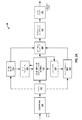
[0028]図1Aは、本開示で説明する態様による技法を利用し得る例示的なビデオコード化システム10を示すブロック図である。本明細書で使用し説明する「ビデオコーダ」又は「コーダ」という用語は、ビデオエンコーダとビデオデコーダの両方を総称的に指す。本開示では、「ビデオコード化」又は「コード化」という用語は、ビデオ符号化とビデオ復号とを総称的に指すことがある。ビデオエンコーダ及びビデオデコーダに加えて、本出願で説明する態様は、トランスコーダ(例えば、ビットストリームを復号し、別のビットストリームを再符号化することができる機器)及びミドルボックス(例えば、ビットストリームを変更、変換及び/又は場合によっては操作することができる機器)など、他の関係する機器に拡張され得る。
[0028] FIG. 1A is a block diagram illustrating an example
[0029]図1Aに示されているように、ビデオコード化システム10は、宛先機器14によって後で復号されるべき符号化ビデオデータを生成する発信源機器12を含む。図1Aの例では、発信源機器12及び宛先機器14は、別個の機器を構成する。但し、発信源機器12及び宛先機器14は、図1Bの例に示されているように、同じ機器上にあるか、又はそれの一部であり得ることに留意されたい。
[0029] As shown in FIG. 1A, the
[0030]もう一度図1Aを参照すると、発信源機器12及び宛先機器14は、それぞれ、デスクトップコンピュータ、ノートブック(例えば、ラップトップ)コンピュータ、タブレットコンピュータ、セットトップボックス、所謂「スマート」フォンなどの電話ハンドセット、所謂「スマート」パッド、テレビジョン、カメラ、表示装置、デジタルメディアプレーヤ、ビデオゲームコンソール、車内コンピュータ、ビデオストリーミング機器、アイウェア及び/又はウェアラブルコンピュータなど、エンティティ(例えば、人間、動物及び/又は別の被制御機器)によって(に)装着可能な(又は着脱自在に取付け可能な)機器、エンティティ内で消費、摂取、又は配置され得る機器又は装置などを含む、広範囲にわたる機器のいずれかを備え得る。様々な実施形態では、発信源機器12及び宛先機器14は、ワイヤレス通信のために装備され得る。
[0030] Referring once again to FIG. 1A, the
[0031]宛先機器14は、復号されるべき符号化ビデオデータをリンク16を介して受信し得る。リンク16は、発信源機器12から宛先機器14に符号化ビデオデータを移動することが可能な任意のタイプの媒体又は機器を備え得る。図1Aの例では、リンク16は、発信源機器12が符号化ビデオデータをリアルタイムで宛先機器14に送信することを可能にするための通信媒体を備え得る。符号化ビデオデータは、ワイヤレス通信プロトコルなどの通信規格に従って変調され、宛先機器14に送信され得る。通信媒体は、無線周波数(RF)スペクトル又は1つ以上の物理伝送線路など、任意のワイヤレス又はワイヤード通信媒体を備え得る。通信媒体は、ローカルエリアネットワーク、ワイドエリアネットワーク又はインターネットなどのグローバルネットワークなど、パケットベースネットワークの一部を形成し得る。通信媒体は、ルータ、スイッチ、基地局又は発信源機器12から宛先機器14への通信を可能にするために有用であり得る任意の他の機器を含み得る。
[0031]
[0032]図1Aの例では、発信源機器12は、ビデオ発信源18と、ビデオエンコーダ20と、出力インターフェース22とを含む。場合によっては、出力インターフェース22は、変調器/復調器(モデム)及び/又は送信機を含み得る。発信源機器12において、ビデオ発信源18は、撮像装置、例えばビデオカメラ、以前に撮られたビデオを含んでいるビデオアーカイブ、ビデオコンテンツプロバイダからビデオを受信するためのビデオフィードインターフェース及び/又は発信源ビデオとしてコンピュータグラフィックスデータを生成するためのコンピュータグラフィックスシステムなどの発信源、若しくはそのような発信源の組合せを含み得る。一例として、ビデオ発信源18がビデオカメラである場合、発信源機器12及び宛先機器14は、図1Bの例に示されているように、所謂「カメラフォン」又は「ビデオフォン」を形成し得る。但し、本開示で説明する技法は、概してビデオコード化に適用可能であり得、ワイヤレス及び/又はワイヤード適用例に適用され得る。
In the example of FIG. 1A,
[0033]撮られたビデオ、以前に撮られたビデオ、又はコンピュータ生成されたビデオは、ビデオエンコーダ20によって符号化され得る。符号化ビデオデータは、発信源機器12の出力インターフェース22を介して宛先機器14に送信され得る。符号化ビデオデータは、更に(又は代替として)、復号及び/又は再生のための宛先機器14又は他の機器による後のアクセスのために記憶装置31上に記憶され得る。図1A及び図1Bに示されているビデオエンコーダ20は、図2A示されているビデオエンコーダ20、又は本明細書で説明する他のビデオエンコーダを備え得る。
[0033] A captured video, a previously captured video, or a computer-generated video may be encoded by the
[0034]図1Aの例では、宛先機器14は、入力インターフェース28と、ビデオデコーダ30と、表示装置32とを含む。場合によっては、入力インターフェース28は、受信機及び/又はモデムを含み得る。宛先機器14の入力インターフェース28は、リンク16を介して及び/又は記憶装置31から符号化ビデオデータを受信し得る。リンク16を介して通信され、又は記憶装置31上に与えられた符号化ビデオデータは、ビデオデータを復号する際に、ビデオデコーダ30などのビデオデコーダが使用するためのビデオエンコーダ20によって生成される様々なシンタックス要素を含み得る。そのようなシンタックス要素は、通信媒体上で送信された、記憶媒体上に記憶された、又はファイルサーバ記憶された符号化ビデオデータに含まれ得る。図1A及び図1Bに示されているビデオデコーダ30は、図2Bに示されているビデオデコーダ30、又は本明細書で説明する他のビデオデコーダを備え得る。
In the example of FIG. 1A,
[0035]表示装置32は、宛先機器14と一体化されるか、又はその外部にあり得る。幾つかの例では、宛先機器14は、一体型表示装置を含み、また、外部表示装置とインターフェースするように構成され得る。他の例では、宛先機器14は表示装置であり得る。概して、表示装置32は、復号ビデオデータをユーザに対して表示し、液晶表示器(LCD)、プラズマ表示器、有機発光ダイオード(OLED)表示器、又は別のタイプの表示装置など、様々な表示装置のいずれかを備え得る。
[0035] The
[0036]関係する態様では、図1Bは例示的なビデオコード化システム10’を示し、ここにおいて、発信源機器12及び宛先機器14は機器11上にあるか、又はそれの一部である。機器11は、「スマート」フォンなどの電話ハンドセットであり得る。機器11は、発信源機器12及び宛先機器14と動作可能に通信している(随意に存在する)プロセッサ/コントローラ機器13を含み得る。図1Bのビデオコード化システム10’及びそれの構成要素は、場合によっては図1Aのビデオコード化システム10及びそれの構成要素と同様である。
[0036] In a related aspect, FIG. 1B shows an exemplary video encoding system 10 ', where
[0037]ビデオエンコーダ20及びビデオデコーダ30は、DSCなど、ビデオ圧縮規格に従って動作し得る。代替的に、ビデオエンコーダ20及びビデオデコーダ30は、代替的にMPEG−4,Part10,AVCと呼ばれるITU−T H.264規格、HEVCなど、他のプロプライエタリ規格又は業界規格、あるいはそのような規格の拡張に従って動作し得る。但し、本開示の技法は、いかなる特定のコード化規格にも限定されない。ビデオ圧縮規格の他の例としては、MPEG−2及びITU−T H.263がある。
[0037]
[0038]図1A及び図1Bの例には示されていないが、ビデオエンコーダ20及びビデオデコーダ30は、それぞれオーディオエンコーダ及びデコーダと統合され得、共通のデータストリーム又は別個のデータストリーム中のオーディオとビデオの両方の符号化を処理するために、適切なMUX−DEMUXユニット、又は他のハードウェア及びソフトウェアを含み得る。適用可能な場合、幾つかの例では、MUX−DEMUXユニットは、ITU H.223マルチプレクサプロトコル、又はユーザデータグラムプロトコル(UDP)などの他のプロトコルに準拠し得る。
[0038] Although not shown in the example of FIGS. 1A and 1B,
[0039]ビデオエンコーダ20及びビデオデコーダ30はそれぞれ、1つ又は複数のマイクロプロセッサ、デジタル信号プロセッサ(DSP)、特定用途向け集積回路(ASIC)、フィールドプログラマブルゲートアレイ(FPGA)、ディスクリート論理回路、ソフトウェア、ハードウェア、ファームウェアなど、様々な好適なエンコーダ回路のいずれか、又はそれらの任意の組合せとして実装され得る。本技法が部分的にソフトウェアで実装されるとき、機器は、ソフトウェアのための命令を好適な非一時的コンピュータ可読媒体に記憶し、本開示の技法を実行するために1つ又は複数のプロセッサを使用してハードウェアでその命令を実行し得る。ビデオエンコーダ20及びビデオデコーダ30の各々は1つ又は複数のエンコーダ又はデコーダ中に含まれ得、そのいずれも、それぞれの機器において複合エンコーダ/デコーダの一部として統合され得る。
[0039]
ビデオコード化プロセス
[0040]上記で手短に述べたように、ビデオエンコーダ20はビデオデータを符号化する。ビデオデータは1つ又は複数のピクチャを備え得る。ピクチャの各々は、ビデオの一部を形成する静止画像である。幾つかの事例では、ピクチャはビデオ「フレーム」と呼ばれることがある。ビデオエンコーダ20がビデオデータを符号化するとき、ビデオエンコーダ20はビットストリームを生成し得る。ビットストリームは、ビデオデータのコード化表現を形成するビットのシーケンスを含み得る。ビットストリームはコード化ピクチャと関連データとを含み得る。コード化ピクチャはピクチャのコード化表現である。
Video coding process
[0040] As briefly mentioned above,
[0041]ビットストリームを生成するために、ビデオエンコーダ20は、ビデオデータ中の各ピクチャに対して符号化演算を実行し得る。ビデオエンコーダ20がピクチャに対して符号化演算を実行するとき、ビデオエンコーダ20は、一連のコード化ピクチャと関連データとを生成し得る。関連データは、QPなどのコード化パラメータのセットを含み得る。コード化ピクチャを生成するために、ビデオエンコーダ20は、ピクチャを等しいサイズのビデオブロックに区分し得る。ビデオブロックはサンプルの2次元アレイであり得る。コード化パラメータは、ビデオデータのあらゆるブロックについてコード化オプション(例えば、コード化モード)を定義し得る。コード化オプションは、所望のレート歪み性能を達成するために選択され得る。
[0041] To generate a bitstream,
[0042]幾つかの例では、ビデオエンコーダ20はピクチャを複数のスライスに区分し得る。スライスの各々は、画像又はフレーム中の領域の残りからの情報なしに独立して復号され得る、画像(例えば、フレーム)中の空間的に別個の領域を含み得る。各画像又はビデオフレームは単一のスライス中で符号化され得るか、若しくは各画像又はビデオフレームは幾つかのスライス中で符号化され得る。DSCでは、各スライスを符号化するために割り振られるターゲットビットは、実質的に一定であり得る。ピクチャに対して符号化演算を実行することの一部として、ビデオエンコーダ20は、ピクチャの各スライスに対して符号化演算を実行し得る。ビデオエンコーダ20がスライスに対して符号化演算を実行するとき、ビデオエンコーダ20は、スライスに関連付けられた符号化データを生成し得る。スライスに関連付けられた符号化データは「コード化スライス(coded slice)」と呼ばれることがある。
[0042] In some examples,
DSCビデオエンコーダ
[0043]図2Aは、本開示で説明する態様による技法を実装し得るビデオエンコーダ20の一例を示すブロック図である。ビデオエンコーダ20は、本開示の技法の一部又は全部を実行するように構成され得る。幾つかの例では、本開示で説明する技法は、ビデオエンコーダ20の様々な構成要素間で共有され得る。幾つかの例では、追加又は代替として、プロセッサ(図示せず)が、本開示で説明する技法の一部又は全部を実行するように構成され得る。
DSC video encoder
[0043] FIG. 2A is a block diagram illustrating an example of a
[0044]説明の目的で、本開示では、DSCコード化のコンテキストにおいてビデオエンコーダ20について説明する。但し、本開示の技法は、他のコード化規格又は方法に適用可能であり得る。
[0044] For purposes of explanation, this disclosure describes
[0045]図2Aの例では、ビデオエンコーダ20は複数の機能構成要素を含む。ビデオエンコーダ20の機能構成要素は、色空間変換器105と、バッファ110と、平坦度検出器115と、レートコントローラ120と、予測器、量子化器、及び再構成器構成要素125と、ラインバッファ130と、インデックスカラー履歴135と、エントロピーエンコーダ140と、サブストリームマルチプレクサ145と、レートバッファ150とを含む。他の例では、ビデオエンコーダ20は、より多数の、より少数の、又は異なる機能構成要素を含み得る。
[0045] In the example of FIG. 2A,
[0046]色空間変換器105は、入力色空間をコード化実施形態において使用される色空間に変換し得る。例えば、例示的な一実施形態では、入力ビデオデータの色空間は、赤、緑及び青(RGB)色空間中にあり、コード化は、ルミナンスY、クロミナンスグリーンCg及びクロミナンスオレンジCo(YCoCg)色空間において実装される。色空間変換は、ビデオデータへのシフト及び追加を含む(1つ又は複数の)方法によって実行され得る。他の色空間中の入力ビデオデータが処理され得、他の色空間への変換も実行され得ることに留意されたい。
[0046] The
[0047]関係する態様では、ビデオエンコーダ20は、バッファ110、ラインバッファ130及び/又はレートバッファ150を含み得る。例えば、バッファ110は、色空間変換されたビデオデータを、ビデオエンコーダ20の他の部分によるそれの使用に先立って保持し得る。別の例では、色空間変換されたデータはより多くのビットを必要とし得るので、ビデオデータはRGB色空間中で記憶され得、色空間変換が必要に応じて実行され得る。
[0047] In a related aspect,
[0048]レートバッファ150はビデオエンコーダ20においてレート制御機構の一部として機能し得、このことについて、レートコントローラ120に関して以下でより詳細に説明する。各ブロックを符号化することに費やされるビットは、大いに、実質的に、ブロックの性質に基づいて変動することがある。レートバッファ150は、圧縮されたビデオにおけるレート変動を平滑化することができる。幾つかの実施形態では、ビットがCBRでバッファから取り出されるCBRバッファモデルが採用される。CBRバッファモデルでは、ビデオエンコーダ20がビットストリームにあまりに多くのビットを加えた場合、レートバッファ150はオーバーフローし得る。一方、ビデオエンコーダ20は、レートバッファ150のアンダーフローを防ぐために、十分なビットを加えなければならない。
[0048] The
[0049]ビデオデコーダ側では、ビットは、固定ビットレートでビデオデコーダ30のレートバッファ155(以下で更に詳細に説明する図2Bを参照)に加えられ得、ビデオデコーダ30は、各ブロックについて可変数のビットを削除し得る。適切な復号を保証するために、ビデオデコーダ30のレートバッファ155は、圧縮されたビットストリームの復号中に「アンダーフロー」又は「オーバーフロー」すべきでない。
[0049] On the video decoder side, bits may be added to the rate buffer 155 of the video decoder 30 (see FIG. 2B, described in further detail below) at a fixed bit rate, and the
[0050]幾つかの実施形態では、バッファフルネス(BF)は、バッファに現在あるビットの数を表す値BufferCurrentSizeと、レートバッファ150のサイズ、即ち、任意の時点においてレートバッファ150に記憶され得るビットの最大数を表すBufferMaxSizeとに基づいて定義され得る。BFは次のように計算され得る。
BF = ((BufferCurrentSize * 100) / BufferMaxSize)
[0050] In some embodiments, the buffer fullness (BF) may be stored in the
BF = ((BufferCurrentSize * 100) / BufferMaxSize)
[0051]BFを計算することへの上記の手法は、例にすぎず、BFは、特定の実施形態又はコンテキストに応じて、任意の数の異なる方法で計算され得ることに留意されたい。 [0051] It should be noted that the above approach to calculating BF is only an example, and BF may be calculated in any number of different ways, depending on the particular embodiment or context.
[0052]平坦度検出器115は、ビデオデータ中の複雑な(即ち、平坦でない)エリアからビデオデータ中の平坦な(即ち、単純な又は均一な(uniform))エリアへの変化、及び/又はその逆の変化を検出することができる。「複雑な」及び「平坦な」という用語は、本明細書では、概して、ビデオエンコーダ20がビデオデータのそれぞれの領域を符号化することの困難さを指すために使用する。従って、本明細書で使用する複雑なという用語は、概して、ビデオデータの領域が、ビデオエンコーダ20が符号化することが複雑であることを表し、例えば、テクスチャードビデオデータ、高い空間周波数、及び/又は符号化することが複雑である他の特徴を含み得る。本明細書で使用する平坦なという用語は、概して、ビデオデータの領域が、ビデオエンコーダ20がエンコーダすることが単純であることを表し、例えば、ビデオデータ中の滑らかな勾配、低い空間周波数、及び/又は符号化することが単純である他の特徴を含み得る。複雑な領域から平坦な領域への遷移が、符号化ビデオデータ中の量子化アーティファクトを低減するために、ビデオエンコーダ20によって使用され得る。詳細には、レートコントローラ120、並びに予測器、量子化器、及び再構成器構成要素125は、複雑な領域から平坦な領域への遷移が識別されたとき、そのような量子化アーティファクトを低減することができる。同様に、平坦な領域から複雑な領域への遷移が、現在ブロックをコード化するために必要とされる予想レートを低減するためにQPを増加させるために、ビデオエンコーダ20によって使用され得る。
[0052] The
[0053]レートコントローラ120は、コード化パラメータのセット、例えば、QPを決定する。QPは、レートバッファ150がオーバーフロー又はアンダーフローしないことを保証するターゲットビットレートについてピクチャ品質を最大にするために、レートバッファ150のバッファフルネスとビデオデータの画像アクティビティ(例えば、複雑な領域から平坦な領域への遷移又はその逆の遷移)とに基づいて、レートコントローラ120によって調整され得る。レートコントローラ120はまた、最適レート歪み性能を達成するために、ビデオデータの各ブロックについて特定のコード化オプション(例えば、特定のモード)を選択する。レートコントローラ120は、再構成された画像の歪みを、それがビットレート制約を満たすように、即ち、全体的実コード化レートがターゲットビットレート内に収まるように最小限に抑える。従って、レートコントローラ120の1つの目的は、レート歪み性能を最大にしながらレートに対する瞬間的及び平均的な制約を満たすように、(1つ又は複数の)QP、(1つ又は複数の)コード化モードなど、コード化パラメータのセットを決定することである。
[0053] The rate controller 120 determines a set of coding parameters, eg, QP. The QP is designed to flatten out the buffer fullness of the
[0054]予測器、量子化器、及び再構成器構成要素125は、ビデオエンコーダ20の少なくとも3つの符号化演算を実行し得る。予測器、量子化器、及び再構成器構成要素125は、幾つかの異なるモードで予測を実行し得る。1つの例示的なプレディケーションモードは、メディアン適応予測の変更バージョンである。メディアン適応予測はロスレスJPEG規格(JPEG−LS)によって実装され得る。予測器、量子化器、及び再構成器構成要素125によって実行され得るメディアン適応予測の変更バージョンは、3つの連続するサンプル値の並列予測を可能にし得る。別の例示的な予測モードはブロック予測である。ブロック予測では、サンプルは、上のライン中の、又は同じライン中の左側の前に再構成された画素からに予測される。幾つかの実施形態では、ビデオエンコーダ20及びビデオデコーダ30は、両方とも、ブロック予測使用を決定するために、再構成された画素に対して同じ探索を実行し得、従って、ビットはブロック予測モードで送られる必要がない。他の実施形態では、ビデオエンコーダ20は、探索を実行し、ビットストリームでブロック予測ベクトルを信号伝達(signal)し得、従って、ビデオデコーダ30は、別個の探索を実行する必要がない。成分範囲の中点を使用してサンプルが予測される中点予測モードも実装され得る。中点予測モードは、ワーストケースサンプルにおいてさえも、圧縮されたビデオに必要なビットの数の制限を可能にし得る。
[0054] The predictor, quantizer, and reconstructor component 125 may perform at least three encoding operations of
[0055]予測器、量子化器、及び再構成器構成要素125はまた、量子化を実行する。例えば、量子化は、シフタを使用して実装され得る2のべき乗量子化器(power-of-2 quantizer)を介して実行され得る。2のべき乗量子化器の代わりに他の量子化技法が実装され得ることに留意されたい。予測器、量子化器、及び再構成器構成要素125によって実行される量子化は、レートコントローラ120によって決定されたQPに基づき得る。最終的に、予測器、量子化器、及び再構成器構成要素125はまた、予測値に逆量子化された残差を加算することと、結果がサンプル値の有効範囲の外側にないことを保証することとを含む再構成を実行する。 [0055] The predictor, quantizer, and reconstructor component 125 also performs quantization. For example, the quantization may be performed via a power-of-2 quantizer that may be implemented using a shifter. Note that other quantization techniques may be implemented instead of a power-of-two quantizer. The quantization performed by the predictor, quantizer, and reconstructor component 125 may be based on the QP determined by the rate controller 120. Finally, the predictor, quantizer, and reconstructor component 125 also adds the dequantized residual to the predicted value and confirms that the result is not outside the valid range of sample values. Perform a reconfiguration that includes guaranteeing.
[0056]予測器、量子化器、及び再構成器構成要素125によって実行される予測、量子化、及び再構成に対する上記で説明した例示的な手法は、例示的なものにすぎず、他の手法が実装され得ることに留意されたい。また、予測器、量子化器、及び再構成器構成要素125は、予測、量子化、及び/又は再構成を実行するための(1つ又は複数の)副構成要素を含み得ることに留意されたい。更に、予測、量子化、及び/又は再構成は、予測器、量子化器、及び再構成器構成要素125の代わりに幾つかの別個のエンコーダ構成要素によって実行され得ることに留意されたい。 [0056] The exemplary techniques described above for the prediction, quantization, and reconstruction performed by the predictor, quantizer, and reconstructor component 125 are merely exemplary and other Note that the approach can be implemented. It is also noted that the predictor, quantizer, and reconstructor component 125 may include subcomponent (s) for performing prediction, quantization, and / or reconstruction. I want. Further, it should be noted that prediction, quantization, and / or reconstruction may be performed by several separate encoder components instead of the predictor, quantizer, and reconstructor component 125.
[0057]ラインバッファ130は、予測器、量子化器、及び再構成器構成要素125並びにインデックスカラー履歴135が、バッファされたビデオデータを使用することができるように、予測器、量子化器、及び再構成器構成要素125からの出力を保持する。インデックスカラー履歴135は、最近使用された画素値を記憶する。これらの最近使用された画素値は、専用シンタックスを介してビデオエンコーダ20によって直接参照され得る。
[0057] The
[0058]エントロピーエンコーダ140は、インデックスカラー履歴135と、平坦度検出器115によって識別された平坦度遷移とに基づいて、予測器、量子化器、及び再構成器構成要素125から受信された予測残差及び他のデータ(例えば、予測器、量子化器、及び再構成器構成要素125によって識別されたインデックス)を符号化する。幾つかの例では、エントロピーエンコーダ140は、サブストリームエンコーダごとにクロックごとに3つのサンプルを符号化し得る。サブストリームマルチプレクサ145は、ヘッダレスパケット多重化方式に基づいてビットストリームを多重化し得る。これは、ビデオデコーダ30が並列に3つのエントロピーデコーダを動作させることを可能にし、クロックごとの3つの画素の復号を可能にする。サブストリームマルチプレクサ145は、パケットがビデオデコーダ30によって効率的に復号され得るようにパケット順序を最適化し得る。クロックごとの2のべき乗個の画素(例えば、2つの画素/クロック又は4つの画素/クロック)の復号を可能にし得る、エントロピーコード化に対する異なる手法が実装され得ることに留意されたい。
[0058] The entropy encoder 140 predicts received from the predictor, quantizer, and reconstructor components 125 based on the
DSCビデオデコーダ
[0059]図2Bは、本開示で説明する態様による技法を実装し得るビデオデコーダ30の一例を示すブロック図である。ビデオデコーダ30は、本開示の技法の一部又は全部を実行するように構成され得る。幾つかの例では、本開示で説明する技法は、ビデオデコーダ30の様々な構成要素間で共有され得る。幾つかの例では、追加又は代替として、プロセッサ(図示せず)が、本開示で説明する技法の一部又は全部を実行するように構成され得る。
DSC video decoder
[0059] FIG. 2B is a block diagram illustrating an example of a
[0060]説明の目的で、本開示では、DSCコード化のコンテキストにおいてビデオデコーダ30について説明する。但し、本開示の技法は、他のコード化規格又は方法に適用可能であり得る。
[0060] For purposes of explanation, this disclosure describes
[0061]図2Bの例では、ビデオデコーダ30は複数の機能構成要素を含む。ビデオデコーダ30の機能構成要素は、レートバッファ155と、サブストリームデマルチプレクサ160と、エントロピーデコーダ165と、レートコントローラ170と、予測器、量子化器、及び再構成器構成要素175と、インデックスカラー履歴180と、ラインバッファ185と、色空間変換器190とを含む。ビデオデコーダ30の図示された構成要素は、図2A中のビデオエンコーダ20に関して上記で説明した対応する構成要素に類似する。従って、ビデオデコーダ30の構成要素の各々は、上記で説明したビデオエンコーダ20の対応する構成要素と同様の様式で動作し得る。
[0061] In the example of FIG. 2B,
QP計算
[0062]1つの手法では、(currQPとして示される)現在ブロックのためのQPは、以下の式に基づいて導出又は計算され得る。
currQP = prevQ + QpAdj * (diffBits > 0 ? 1: -1),
QP calculation
[0062] In one approach, the QP for the current block (denoted as currQP) may be derived or calculated based on the following equation:
currQP = prevQ + QpAdj * (diffBits> 0? 1: -1),
[0063]ここで、prevQPは、前のブロックに関連付けられたQPであり、diffBitsは、previousBlockBitsとtargetBitsとの間の差を表し、QpAdjは、diffBitsの大きさに基づいて計算されるQPオフセット値(例えば、QP調整値)であり、previousBlockBitsは、前のブロックをコード化するために使用されるビットの数を表し、targetBitsは、現在ブロックをコード化するためのビットのターゲット数を表す。previousBlockBits>targetBitsであるとき、diffBitsは正であり、現在ブロックQPは、prevQP値にオフセット値QpAdjを加算することによって導出され得る。言い換えれば、QP値は、diffBitsが正であるとき、prevQP値から値が減少しない。previousBlockBits≦targetBitsであるとき、diffBitsは負又は0であり、currQPはprevQP値から増加しない。オフセット値QpAdjは、例えば、diffBitsの大きさが増加するにつれてQpAdjが単調に増加するような方法で、diffBitsの関数として計算され得ることに留意されたい。 [0063] where prevQP is the QP associated with the previous block, diffBits represents the difference between previousBlockBits and targetBits, and QpAdj is a QP offset value calculated based on the magnitude of diffBits (Eg, QP adjustment value), previousBlockBits represents the number of bits used to code the previous block, and targetBits represents the target number of bits for coding the current block. When previousBlockBits> targetBits, diffBits is positive and the current block QP can be derived by adding the offset value QpAdj to the prevQP value. In other words, the QP value does not decrease from the prevQP value when diffBits is positive. When previousBlockBits ≦ targetBits, diffBits is negative or 0 and currQP does not increase from the prevQP value. Note that the offset value QpAdj can be calculated as a function of diffBits, for example in such a way that QpAdj increases monotonically as the magnitude of diffBits increases.
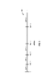
[0064]次に、本明細書ではデフォルトの技法と呼ぶ、QP調整値QpAdjを計算するための1つの技法について、図3を参照しながら説明する。図3は、0を始めるdiffBitsの値がプロットされる軸を含む、グラフ300を与える。デフォルトの技法では、diffBits>0であるとき、diffBitsは、K個の閾値を使用してK+1個の範囲に分類され得る。これらの閾値は、ラベル、閾値1、閾値2、閾値3、...、及び閾値Kによって示され、範囲は、ラベル、範囲1、範囲2、範囲3、...、及び範囲K+1によって示される。図3のデフォルト技法では、K個の閾値を使用して、diffBitsをK+1個の範囲にセグメント化することへの1つの手法が示されている。各範囲は、特定のQpAdj値に関連付けられ得、ここで、QpAdj値は、範囲インデックスが増加するにつれて増加する。diffBits≦0であるとき、diffBitsの絶対値は、J個の閾値を使用してJ+1個の範囲に分類され得(図示せず)、J+1個の範囲の各々のために割り当てられた特定のQpAdj値があり得る。
[0064] Next, one technique for calculating the QP adjustment value QpAdj, referred to herein as the default technique, will be described with reference to FIG. FIG. 3 provides a
[0065]他の態様では、currQP値は、バッファのアンダーフロー及び/又はオーバーフローを防ぐために、(バッファフルネスBFとして表され得る)バッファのフルネスに基づいて調整され得る。特に、BFがある閾値(例えば、P1)を超えるとき、currQPは固定オフセット値(例えば、p1)だけ増分され得る。例えば、currQPは次のように調整され得、即ち、currQP+=p1である。更に、BFがある閾値(例えば、Q1)を下回るとき、currQPはq1だけ減分され得、例えば、currQP−=q1である。ある態様では、複数の閾値が採用され得、各閾値について、currQPを調整するための対応するオフセット値があり得る。 [0065] In other aspects, the currQP value may be adjusted based on buffer fullness (which may be represented as buffer fullness BF) to prevent buffer underflow and / or overflow. In particular, currQP may be incremented by a fixed offset value (eg, p 1 ) when BF exceeds a certain threshold (eg, P 1 ). For example, currQP may be adjusted as follows: currQP + = p 1 . Further, when BF falls below a certain threshold (eg, Q 1 ), currQP may be decremented by q 1 , eg, currQP− = q 1 . In certain aspects, multiple thresholds may be employed, and for each threshold there may be a corresponding offset value for adjusting currQP.
[0066]複雑な領域から平坦な領域への遷移が識別されるとき、又は平坦な領域が識別されるとき、以下で更に詳細に説明するように、currQPは低い値(例えば、定義されたcurrQP値を下回る値)に設定され得る。
平坦な領域から複雑な領域への遷移を検出すること
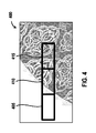
[0067]図4を参照すると、1つ又は複数の技法が、平坦な/滑らかな領域から複雑な領域への遷移を検出するために利用され得る。図4は、フレーム、又は、例えばフレームのスライスのような、それの部分であり得る、例示的な関心領域400を示す。領域400は、及び3つの連続するブロック405、410及び415を含み得る。この例では、ブロック405は領域400の平坦な領域/部分に対応し、ブロック410は領域400の遷移領域/部分に対応し、ブロック415は領域400の複雑な領域/部分に対応する。図示のように、ブロック405のコンテンツは、平坦、滑らか、又は均一である。ブロック415のコンテンツは、テクスチャードであり、全体を通して均一ではないパターンを呈する。ブロック410は、均一なコンテンツから均一でないコンテンツへの遷移を含む。以下で説明するように、複雑さ計算がブロック405、410及び415の各々について実行されなされる。
[0066] When a transition from a complex region to a flat region is identified, or when a flat region is identified, currQP is a low value (eg, a defined currQP as described in more detail below). A value less than the value).
Detecting transitions from flat areas to complex areas
[0067] Referring to FIG. 4, one or more techniques may be utilized to detect a transition from a flat / smooth region to a complex region. FIG. 4 shows an exemplary region of
[0068]本明細書で使用する、平坦なブロックは、複雑さ閾値よりも低い複雑さ値を有するブロックを指すことがある。そこにおいてブロックが平坦であると決定される閾値は、ブロックをコード化するために必要とされるビットの数などの様々な設計基準に基づいて設定され得る。同様に、平坦でない又は複雑なブロックは、平坦でない、例えば、複雑さ閾値よりも大きいか、又はそれに等しい複雑さ値を有するブロックを指すことがある。ブロックの関連付けられた複雑さに基づいてブロックの様々な他のカテゴリー分類が採用され得、そのようなカテゴリー分類は、ブロックの複雑さ値における閾値によって定義される範囲であり得る。 [0068] As used herein, a flat block may refer to a block having a complexity value lower than the complexity threshold. The threshold at which a block is determined to be flat may be set based on various design criteria such as the number of bits required to code the block. Similarly, an uneven or complex block may refer to a block that is not flat, eg, has a complexity value that is greater than or equal to a complexity threshold. Various other categorizations of the block may be employed based on the associated complexity of the block, and such categorization may be in a range defined by a threshold in the block complexity value.
[0069]平坦な及び複雑なという用語は、ブロック以外の領域にも適用され得る。この場合、領域は、ブロックと同じサイズでないことがあり、例えば、領域は、個別に符号化/復号されるサイズではないことがあるが、領域はまた、領域の複雑さに基づいて平坦又は複雑としてカテゴリー分類され得る。例えば、領域は、その領域内の各ブロックが平坦なブロックである場合、平坦な領域と呼ばれることがある。但し、平坦な領域は、その中に含まれているブロックと同じ境界を有しないことがあり、得る領域の複雑さは、領域全体にわたって計算され得る。複雑な領域が、同様に定義され得る。従って、領域は、領域の複雑さ値を、ブロックの複雑さ閾値とは異なり得る複雑さ閾値と比較することによって、平坦又は複雑としてカテゴリー分類され得る。更に、コード化のために領域がブロックに分割され得るので、領域という用語は、本明細書では、本開示の様々な態様の理解を可能にするために概念的に使用され得る。 [0069] The terms flat and complex may be applied to areas other than blocks. In this case, the region may not be the same size as the block, for example, the region may not be a size that is individually encoded / decoded, but the region may also be flat or complex based on the complexity of the region. Can be categorized as For example, a region may be referred to as a flat region if each block in that region is a flat block. However, a flat region may not have the same boundaries as the blocks contained therein, and the complexity of the resulting region can be calculated over the entire region. Complex areas can be defined as well. Thus, a region can be categorized as flat or complex by comparing the complexity value of the region with a complexity threshold that can be different from the complexity threshold of the block. Further, since a region can be divided into blocks for encoding, the term region can be used conceptually herein to allow an understanding of various aspects of the disclosure.
[0070]上記で説明したように、ブロックを平坦又は複雑としてカテゴリー分類するために、ブロックの複雑さ値が決定され得る。ブロックの複雑さ値は、複雑さ値が、ブロックを符号化することの困難を表す限り、様々な技法、例えば、可視アーティファクトを導入することなしにブロックをコード化するために必要とされ得るビットの数に従って決定され得る。 [0070] As described above, in order to categorize a block as flat or complex, the complexity value of the block may be determined. The block complexity value is a bit that may be required to code the block without introducing various techniques, such as visual artifacts, as long as the complexity value represents the difficulty of encoding the block. Can be determined according to the number of
[0071]提案される平坦度検出技法のフレームワークが、図5の例示的な複雑さ検出システム500に示されている。システム500は、図4のブロック405、410及び415、又はそのようなブロックに関する情報を入力として受信し得る。一実装形態では、システム500は、Ccur、Cnext及びCprevとして示されるブロックごとの複雑さ値を計算するために、ブロック405、410及び415の各々について複雑さ計算を実行し得る。例えば、システム500は、それぞれブロック405、410及び415の各々に対応する複雑さ計算ユニット505、510及び515を含み得、それぞれ計算する複雑さ値Cprev、Ccur及びCnextを検出器520に出力し得る。別の実施形態では、3つよりも少ない複雑さ値が各ブロックについて計算され得る。例えば、エンコーダは、次のブロック時間についてそれぞれ「前の」及び「現在」複雑さ値になる、所与の時間ブロックにおける「現在」及び「次の」ブロック複雑さ値をバッファ又は記憶し得る。このようにして、次の時間ブロックについて「次の」ブロック複雑さ値のみが計算される必要があることになる。言い方を変えれば、エンコーダは、第2のブロック時間においてそれぞれ「前の」及び「現在」複雑さ値になる、第1の時間ブロックにおける「現在」及び「次の」ブロック複雑さ値をバッファ又は記憶し得、従って、「次の」ブロック複雑さ値のみが第2の時間ブロックにおいて計算される。
[0071] A framework for the proposed flatness detection technique is shown in the exemplary
[0072]関係する態様では、複雑さ計算ユニット505、510及び515及び/又は検出器520は、別個の構成要素、コーデックの同じ構成要素又はプロセッサの部分若しくは1つ以上のプロセッサによって実行されソフトウェアモジュールであり得る。システム500の特徴は、ハードウェア、ソフトウェア、ファームウェア、又はそれらの任意の組合せで実装され得る。更なる関係する態様では、システム500は、関心画像又は領域のための任意の数の連続ブロック(例えば、スライス中の4つの連続ブロック)に関する、又は関係する情報を受信し得、連続ブロックの各々について複雑さ計算を実行し得る。
[0072] In a related aspect, the
[0073]一態様では、ブロックの複雑さは、ブロック中の画素の周波数変換(例えば、離散コサイン変換(DCT)、アダマール変換など)を受けることによって計算され得る。周波数変換は、複雑さ値を生成するために合計され得る、幾つかの周波数係数を生じ得る。別の態様では、直流(DC又はゼロ周波数)係数及び/又は1つ以上の低周波数係数が、合計に含まれないことがある。周波数変換の前に色変換を適用することなど、複雑さ値を決定するための様々な他の技法も実装され得る。 [0073] In one aspect, the complexity of the block may be calculated by undergoing a frequency transform (eg, discrete cosine transform (DCT), Hadamard transform, etc.) of the pixels in the block. A frequency transform can yield several frequency coefficients that can be summed to produce a complexity value. In another aspect, direct current (DC or zero frequency) coefficients and / or one or more low frequency coefficients may not be included in the sum. Various other techniques for determining the complexity value may also be implemented, such as applying a color transform before the frequency transform.
[0074]関係する態様では、ブロックの複雑さ値を計算するために、変換係数の絶対値又は絶対2乗値が合計され得る。更なる関係する態様では、複雑さ値を計算するためにルーマチャネルが使用され得、又は複雑さ値を計算するためにルーマチャネル/クロマチャネルの両方が使用され得る。 [0074] In a related aspect, the absolute value or absolute square value of the transform coefficients may be summed to calculate the complexity value of the block. In further related aspects, a luma channel may be used to calculate the complexity value, or both luma channel / chroma channel may be used to calculate the complexity value.
[0075]また更なる関係する態様では、絶対和又は絶対2乗和を計算する間、変換係数のサブセットが考慮され得、即ち、ブロック中の全てよりも少ない変換係数が、幾つかの例示的な手法において考慮され得る。 [0075] In yet a further related aspect, a subset of transform coefficients may be considered while computing absolute sums or absolute square sums, ie, fewer than all transform coefficients in a block Can be considered in various ways.
[0076]また更なる態様では、各変換係数が重みで乗算され得、ここで、各係数に適用される重みは変動するか又は一定であり得る。次いで、重み付けされた係数の絶対値又は絶対2乗値が計算され得る。 [0076] In yet a further aspect, each transform coefficient may be multiplied by a weight, where the weight applied to each coefficient may vary or be constant. The absolute value or absolute square value of the weighted coefficient can then be calculated.
[0077]もう一度図5の例を参照すると、検出器500は、Cprev、Ccur及びCnextに基づいて、ブロック405、410及び415が平坦な領域から複雑な領域への遷移を含むかどうかを決定し得る。例えば、検出器500の出力は、平坦−複雑領域遷移がないことを示すための0、及び平坦−複雑領域遷移があることを示すための1など、バイナリ結果であり得る。
[0077] Referring to the example of FIG. 5 again,
[0078]平坦な領域から複雑な領域への遷移があるかどうかの決定は、関心領域(例えば、領域400)中の連続ブロック(例えば、ブロック405、410及び415)の複雑さ値に基づいて、1つ又は複数の条件を検査することによって実行され得る。一実施形態では、平坦−複雑領域遷移があるかどうかの決定は、以下の条件1及び条件2を検査することを介して実行される。
条件1:(Cprev<T0)&&(Cnext>T1)
[0078] The determination of whether there is a transition from a flat region to a complex region is based on the complexity values of successive blocks (eg, blocks 405, 410 and 415) in the region of interest (eg, region 400). It can be performed by examining one or more conditions. In one embodiment, the determination of whether there is a flat-complex region transition is performed via examining
Condition 1: (C prev <T 0 ) && (C next > T 1 )
[0079] [0081]条件1に関して、閾値T0及びT1は、コーデックのパラメータに基づいて調整され得る。好ましくは、順序付けT0<T1が従われるべきである。関係する態様では、平坦な領域から複雑な領域への遷移があることを検出することは、(i)前のブロック405が平坦な領域に対応することを示す、前のブロック405の複雑さ値が第1の閾値(例えば、T0)よりも小さい(又は、それよりも小さいか、若しくはそれに等しい)こと、及び(ii)次のブロック415が複雑な領域に対応することを示す、次のブロック415の複雑さ値が第2の閾値(例えば、T1)よりも大きい(又は、それよりも大きいか、若しくはそれに等しい)ことを決定することを含み得る。ここで、前のブロックが平坦な領域に対応すること、及び次のブロック415が複雑な領域に対応することの指示は、現在ブロック410中に平坦な領域から複雑な領域への遷移があること、即ち、現在ブロック410が遷移ブロックであることを更に示す。
条件2:C0=false,C1=false
[0081] For
Condition 2: C 0 = false, C 1 = false
[0080]条件2に関して、条件2中の値C0及びC1は、本質的にブーリアンであり、図6に示されているように、平坦−複雑領域検出の前の履歴を表す。例えば、前のブロック時間の値C0及びC1並びに現在ブロック時間のC2が、メモリ記憶ユニット600に記憶され得る。一態様では、各ブロック時間において、複雑さ値は1だけ左にシフトされる。別の態様では、平坦−複雑領域検出の前の履歴、即ち、前のブロック時間の値C0及びC1は、上記の条件2を検査するために使用される。また別の態様では、条件1の両方の部分が満たされた場合、図6中の値C2は、真に設定されることになる。平坦−複雑領域遷移が検出されたときでも、使用されるQPは、現在/次のブロックをコード化するために必要とされる予想レートを低減するために、遷移ブロック又は遷移ブロックの後の次のブロックにおいて(前の平坦なブロックと比較して)増加させられ得る。但し、遷移ブロックは、部分的に平坦な情報と部分的に複雑な情報の両方を含んでいるので、遷移ブロックにおけるQP値は、あまりに高くなる(例えば、定義されたQP値を超える)ことができないことに留意されたい。例えば、遷移ブロックのためのQP値が、定義されたQP値を超えるとき、遷移ブロックから再構成された画像内で顕著であり得るブロックの平坦なポションにおけるアーティファクトが生成されることがある。
[0080] With respect to condition 2, the values C 0 and C 1 in condition 2 are inherently Boolean and represent the history prior to flat-complex region detection, as shown in FIG. For example, the previous block time values C 0 and C 1 and the current block time C 2 may be stored in the
[0081]従って、QPを増加させることを遷移ブロックの後まで遅延させることが、望ましいことがある。例えば、QPは、検出された遷移ブロックの直後のブロックのために(例えば、ブロック410に続くブロック415のために)増加させられ得る。QPが第1の完全に複雑なブロック(例えば、ブロック415)にとって高い場合、複雑さがアーティファクトの存在をマスキングし得る。
[0081] Accordingly, it may be desirable to delay increasing the QP until after the transition block. For example, the QP may be increased for the block immediately following the detected transition block (eg, for
[0082]従って、QPが現在ブロックのために調整されるべきであるかどうかの次の決定は、C1のブール値に依存する。C1が真である場合、現在ブロックのためのQPは、高い値に増加されるべきである。 [0082] Thus, the next determination of whether the QP should be adjusted for the current block depends on the Boolean value of C 1 . If C 1 is true, the QP for the current block should be increased to a high value.
[0083]エンコーダ側において、各新しいブロックを処理することの始めに、検出結果の履歴が更新される。即ち、C1→C0,C2→C1,C2=偽である。これは、現在ブロックの検出結果を計算するより前に行われる。本質的に、これは、平坦−複雑遷移を検出することとQPを調整することとの間に1つのブロックのオフセットを追加する。上記で説明したように、これは、QPが遷移ブロックのために低い値にとどまることを保証する。更に、これは、連続する複数のブロックが平坦−複雑遷移として検出され得ないことを保証する。 [0083] On the encoder side, at the beginning of processing each new block, the history of detection results is updated. That is, C 1 → C 0 , C 2 → C 1 , C 2 = false. This is done before calculating the current block detection result. In essence, this adds an offset of one block between detecting a flat-complex transition and adjusting the QP. As explained above, this ensures that the QP remains low for the transition block. Furthermore, this ensures that consecutive blocks cannot be detected as flat-complex transitions.
[0084]別の例では、条件1中の比較演算子が、異なる比較演算子と置き換えられ得る。例えば、Cprev<T0の代わりに、代わりにCprev≦T0が代わりに使用され得る。
[0084] In another example, the comparison operator in
[0085]上記実施形態の1つの利点は、平坦−複雑領域遷移の検出が、エンコーダが複雑な領域のためにQPを増加させることを可能にすることである。これは、ブロックをコード化するために必要とされる予想レートを減少させることになり、生じるアーティファクトは、領域の複雑さによってマスキングされることになる。また、平坦−複雑遷移検出の結果は、1ビット/ブロックを使用して符号化ビットストリームでデコーダに明示的に信号伝達され得る。これは、デコーダが、エンコーダにおいて行われるように複雑さ値を計算する必要なしに、QPを調整することを可能にする。更に、平坦−複雑領域遷移を検出するための本技法において利用される複雑さ計算及びルックアヘッドデータは、複雑−平坦領域遷移(complex-to-flat region transition)を検出するためにも利用され、それにより、DSCなど、固定レートコーデックのための効率性を実現し得る。一実施形態では、1ビットを使用して平坦−複雑遷移を信号伝達すること(signaling)を含み得る技法が提供される。関係する態様では、平坦−複雑は、一緒にグループ化され得る可能な平坦度検出又は分類のセットのうちの1つである。例えば、平坦度の4つのクラス(例えば、平坦−複雑、複雑−平坦、やや平坦(somewhat flat)及び極めて平坦(very flat))がある場合、結果は、2ビットコードのセットのうちの1つを用いて信号伝達され得る。 [0085] One advantage of the above embodiment is that the detection of flat-complex region transitions allows the encoder to increase the QP for complex regions. This will reduce the expected rate required to code the block and the resulting artifact will be masked by the complexity of the region. Also, the results of flat-complex transition detection can be explicitly signaled to the decoder in the encoded bitstream using 1 bit / block. This allows the decoder to adjust the QP without having to calculate the complexity value as is done at the encoder. In addition, the complexity calculation and look-ahead data utilized in the present technique for detecting flat-complex region transitions can also be used to detect complex-to-flat region transitions, Thereby, efficiency for a fixed rate codec such as DSC may be realized. In one embodiment, techniques are provided that may include signaling flat-complex transitions using one bit. In a related aspect, flat-complexity is one of a set of possible flatness detections or classifications that can be grouped together. For example, if there are four classes of flatness (eg, flat-complex, complex-flat, somewhat flat and very flat), the result is one of a set of 2-bit codes. Can be used to signal.
[0086]一実施形態では、平坦−複雑遷移が識別されたとき、ブロックのQP値は、予め定義された値(例えば、固定の高い値)に設定され得るか、又は、QPは、予め定義された増分又は値(例えば固定調整値)だけ増加させられ得る。
画像の複雑な領域を検出するための例示的なフローチャート
[0087]図7を参照しながら、画像の平坦な領域から複雑な領域への遷移を検出するための例示的なプロシージャについて説明する。画像のスライスが、現在ブロックと、次のブロックと、前のブロックとを含み得る。
[0086] In one embodiment, when a flat-complex transition is identified, the QP value of the block may be set to a predefined value (eg, a fixed high value) or the QP may be predefined. Incremented or incremented by a value (eg, a fixed adjustment value).
Exemplary flowchart for detecting complex regions of an image
[0087] With reference to FIG. 7, an exemplary procedure for detecting a transition from a flat region to a complex region of an image will be described. A slice of the image may include a current block, a next block, and a previous block.
[0088]図7は、本開示の一実施形態による、ビデオデータをコード化するための方法700を示すフローチャートである。図7に示されているステップは、ビデオエンコーダ(例えば、図2A中のビデオエンコーダ20)、ビデオデコーダ(例えば、図2B中のビデオデコーダ30)又は、例えば、平坦度検出器115、レートコントローラ120、予測器、量子化器及び再構成器構成要素125、エントロピーエンコーダ140及びレートバッファ150など、それらの(1つ又は複数の)構成要素によって実行され得る。便宜上、方法700について、ビデオエンコーダ20、ビデオデコーダ30、又は別の構成要素であり得る、(単にコーダとも呼ばれる)ビデオコーダによって実行されるものとして説明する。
[0088] FIG. 7 is a flowchart illustrating a
[0089]コーダ又はそれの(1つ又は複数の)構成要素は、バッファを含む複数のプログラマブル計算ユニットによって共有される集積グローバルメモリを含む、機器上に実装され得、ここにおいて、バッファは先入れ先出し(FIFO)バッファを含み得る。機器は、少なくとも1つのプロセッサ又はプロセッサ回路(例えば、中央処理ユニット(CPU))及び/又はグラフィックス処理ユニット(GPU)を含み得る集積回路(IC)を更に含み得、ここにおいて、GPUは1つ又は複数のプログラマブル計算ユニットを含み得る。 [0089] The coder or component (s) thereof may be implemented on a device including an integrated global memory shared by a plurality of programmable computing units including a buffer, where the buffer is a first in first out ( FIFO) buffer. The apparatus may further include an integrated circuit (IC) that may include at least one processor or processor circuit (eg, a central processing unit (CPU)) and / or a graphics processing unit (GPU), where one GPU Or it may include multiple programmable computing units.
[0090]方法700は、ブロック710において開始する。ブロック710において、コーダは、現在ブロックの現在複雑さ値と、次のブロックの次の複雑さ値と、前のブロックの前の複雑さ値とを計算する。ブロック710は、コーダが、現在ブロック、次のブロック及び前のブロックのうちの各ブロックについて、(i)変換係数を決定するために変換を適用することと、(ii)変換係数の定義された絶対和を決定することとを伴い得る。変換を適用することは、DCT及びアダマール変換のうちの1つを適用することを伴い得る。定義された絶対和を決定することは、変換係数の絶対和及び絶対2乗和のうちの1つを決定することを伴い得る。
[0090] The
[0091]ブロック720において、コーダは、前の複雑さ値が第1の閾値よりも小さいことと、次の複雑さ値が第2の閾値よりも大きいこととを検出し、ここにおいて、第2の閾値は第1の閾値よりも大きい。
[0091] At
[0092]ブロック730において、コーダは、現在ブロックへの遷移も前のブロックへの遷移も平坦−複雑領域遷移ではないと決定する。ここにおいて、コーダは、現在ブロック時間における現在ブロック、次のブロック及び前のブロックの複雑さ値及び/又は1つ以上の前のブロック時間における現在ブロック、次のブロック及び前のブロックの複雑さ値に基づいて、ブロック730を実行する。
[0092] At
[0093]ブロック740において、コーダは、(i)前の複雑さ値が第1の閾値よりも小さいことと、次の複雑さ値が第2の閾値よりも大きいこととを検出すること、及び(ii)現在ブロックへの遷移も前のブロックへの遷移も平坦−複雑領域遷移ではないと決定することに応答して、次のブロックに遷移するときに平坦−複雑領域遷移を検出する。
[0093] At
[0094]ブロック750において、コーダは、随意に、平坦−複雑領域遷移を検出することに応答して、QPを調整し、及び/又は、次のブロックに遷移するときに平坦−複雑領域遷移を検出することに応答して、遷移の指示をコーデックのエンコーダからデコーダに信号伝達し得る。方法700は、ブロック740において又はブロック750において、終了し得る。
他の考慮事項
[0095]本開示の態様について、図2A中のビデオエンコーダ20など、エンコーダの観点から説明したことに留意されたい。しかしながら、上記で説明した動作の逆の動作が、例えば、図2B中のビデオデコーダ30によって、生成されたビットストリームを復号するために適用され得ることを、当業者は諒解されよう。
[0094] In
Other considerations
[0095] Note that aspects of this disclosure have been described in terms of an encoder, such as
[0096]本明細書で開示する情報及び信号は、多種多様な技術及び技法のいずれかを使用して表され得る。例えば、上記の説明全体にわたって言及され得るデータ、命令、コマンド、情報、信号、ビット、シンボル及びチップは、電圧、電流、電磁波、磁界又は磁性粒子、光場又は光学粒子、若しくはそれらの任意の組合せによって表され得る。 [0096] Information and signals disclosed herein may be represented using any of a wide variety of techniques and techniques. For example, data, instructions, commands, information, signals, bits, symbols and chips that may be referred to throughout the above description are voltages, currents, electromagnetic waves, magnetic fields or magnetic particles, light fields or optical particles, or any combination thereof. Can be represented by:
[0097]本明細書で開示する実施形態に関して説明した様々な例示的な論理ブロック及びアルゴリズムステップは、電子ハードウェア、コンピュータソフトウェア、又はその両方の組合せとして実装され得る。ハードウェアとソフトウェアのこの互換性を明確に示すために、様々な例示的な構成要素、ブロック及びステップについて、概してそれらの機能に関して上記で説明した。そのような機能をハードウェアとして実装するか、ソフトウェアとして実装するかは、特定の適用例及び全体的なシステムに課される設計制約に依存する。当業者は、説明した機能を特定の適用例ごとに様々な方法で実装し得るが、そのような実装の決定は、本開示の範囲からの逸脱を生じるものと解釈されるべきではない。 [0097] Various exemplary logic blocks and algorithm steps described with respect to the embodiments disclosed herein may be implemented as electronic hardware, computer software, or a combination of both. To clearly illustrate this interchangeability of hardware and software, various illustrative components, blocks, and steps have been described above generally in terms of their functionality. Whether such functionality is implemented as hardware or software depends upon the particular application and design constraints imposed on the overall system. Those skilled in the art may implement the described functionality in a variety of ways for each particular application, but such implementation decisions should not be construed as departing from the scope of the present disclosure.
[0098]本明細書で説明した技法は、ハードウェア、ソフトウェア、ファームウェア、又はそれらの任意の組合せで実装され得る。そのような技法は、汎用コンピュータ、ワイヤレス通信機器ハンドセット又はワイヤレス通信機器ハンドセット、自動車、アプライアンス、ウェアラブル及び/又は他の機器における適用例を含む複数の用途を有する集積回路機器など、様々な機器のいずれかにおいて実装され得る。機器又は構成要素として説明した特徴は、集積論理機器に一緒に、又は個別であるが相互運用可能な論理機器として別々に実装され得る。ソフトウェアで実装された場合、本技法は、実行されたとき、上記で説明した方法のうちの1つ又は複数を実行する命令を含むプログラムコードを備えるコンピュータ可読データ記憶媒体によって、少なくとも部分的に実現され得る。コンピュータ可読データ記憶媒体は、パッケージング材料を含むことがあるコンピュータプログラム製品の一部を形成し得る。コンピュータ可読媒体は、同期型ダイナミックランダムアクセスメモリ(SDRAM)などのランダムアクセスメモリ(RAM)、読取り専用メモリ(ROM)、不揮発性ランダムアクセスメモリ(NVRAM)、電気消去可能プログラマブル読取り専用メモリ(EEPROM(登録商標))、フラッシュメモリ、磁気又は光学データ記憶媒体など、メモリ又はデータ記憶媒体を備え得る。本技法は、追加又は代替として、伝搬信号又は電波など、命令又はデータ構造の形態でプログラムコードを搬送又は伝達し、コンピュータによってアクセスされ、読み取られ、及び/又は実行され得るコンピュータ可読通信媒体によって、少なくとも部分的に実現され得る。 [0098] The techniques described herein may be implemented in hardware, software, firmware, or any combination thereof. Such techniques may be used in any of a variety of devices, such as general purpose computers, wireless communication device handsets or wireless communication device handsets, integrated circuit devices having multiple uses including applications in automobiles, appliances, wearables and / or other devices. Can be implemented. Features described as devices or components may be implemented together in an integrated logic device or separately as separate but interoperable logic devices. When implemented in software, the techniques are at least partially implemented by a computer-readable data storage medium comprising program code that, when executed, comprises instructions that perform one or more of the methods described above. Can be done. The computer readable data storage medium may form part of a computer program product that may include packaging material. Computer readable media include random access memory (RAM) such as synchronous dynamic random access memory (SDRAM), read only memory (ROM), non-volatile random access memory (NVRAM), electrically erasable programmable read only memory (EEPROM) Trademark)), flash memory, magnetic or optical data storage media, and the like. The techniques additionally or alternatively carry or transmit program code in the form of instructions or data structures such as propagated signals or radio waves and can be accessed, read and / or executed by a computer by a computer-readable communication medium. It can be realized at least in part.
[0099]プログラムコードは、1つ又は複数のデジタル信号プロセッサ(DSP)、汎用マイクロプロセッサ、特定用途向け集積回路(ASIC)、フィールドプログラマブル論理アレイ(FPGA)又は他の等価の集積回路若しくはディスクリート論理回路など、1つ又は複数のプロセッサを含み得るプロセッサによって実行され得る。そのようなプロセッサは、本開示で説明した技法のいずれかを実行するように構成され得る。汎用プロセッサはマイクロプロセッサであり得るが、代替として、プロセッサは、任意の従来のプロセッサ、コントローラ、マイクロコントローラ又は状態機械であり得る。プロセッサはまた、コンピューティング機器の組合せ、例えば、DSPとマイクロプロセッサとの組合せ、複数のマイクロプロセッサ、DSPコアと連携する1つ以上のマイクロプロセッサ又は任意の他のそのような構成として実装され得る。従って、本明細書で使用する「プロセッサ」という用語は、上記の構造、上記の構造の任意の組合せ、又は本明細書で説明した技法の実装に好適な他の構造又は装置のいずれかを指すことがある。更に、幾つかの態様では、本明細書で説明した機能は、符号化及び復号のために構成された専用のソフトウェア若しくはハードウェア内に提供され得、又は複合ビデオエンコーダ/デコーダ(コーデック)に組み込まれ得る。また、本技法は、1つ又は複数の回路又は論理要素で十分に実装され得る。 [0099] The program code may be one or more digital signal processors (DSPs), general purpose microprocessors, application specific integrated circuits (ASICs), field programmable logic arrays (FPGAs), or other equivalent integrated or discrete logic circuits. Etc., which may be executed by a processor that may include one or more processors. Such a processor may be configured to perform any of the techniques described in this disclosure. A general purpose processor may be a microprocessor, but in the alternative, the processor may be any conventional processor, controller, microcontroller, or state machine. The processor may also be implemented as a combination of computing devices, eg, a combination of a DSP and a microprocessor, multiple microprocessors, one or more microprocessors in conjunction with a DSP core, or any other such configuration. Thus, as used herein, the term “processor” refers to any of the above structures, any combination of the above structures, or other structures or devices suitable for implementing the techniques described herein. Sometimes. Further, in some aspects, the functionality described herein may be provided in dedicated software or hardware configured for encoding and decoding, or incorporated into a composite video encoder / decoder (codec). Can be. Also, the techniques may be fully implemented with one or more circuits or logic elements.
[0100]本開示の技法は、ワイヤレスハンドセット、IC又はICのセット(例えば、チップセット)を含む、多種多様な機器又は装置で実装され得る。本開示では、開示する技法を実行するように構成された機器の機能的態様を強調するために、様々な構成要素又はユニットについて説明したが、それらの構成要素又はユニットは、必ずしも異なるハードウェアユニットによる実現を必要とするとは限らない。むしろ、上記で説明したように、様々なユニットが、好適なソフトウェア及び/又はファームウェアとともに、上記で説明した1つ又は複数のプロセッサを含めて、コーデックハードウェアユニットにおいて組み合わせられるか、又は相互動作可能なハードウェアユニットの集合によって与えられ得る。 [0100] The techniques of this disclosure may be implemented in a wide variety of devices or apparatuses, including a wireless handset, an IC or a set of ICs (eg, a chipset). Although this disclosure has described various components or units in order to highlight the functional aspects of an apparatus configured to perform the disclosed techniques, those components or units are not necessarily different hardware units. Realization by is not always necessary. Rather, as described above, the various units may be combined or interoperable in a codec hardware unit, including one or more processors described above, with suitable software and / or firmware. Can be given by a set of hardware units.
[0101]上記について様々な異なる実施形態に関して説明したが、一実施形態からの特徴又は要素は、本開示の教示から逸脱することなく他の実施形態と組み合わせられ得る。但し、それぞれの実施形態間の特徴の組合せは、必ずしもそれに限定されるとは限らない。本開示の様々な実施形態について説明した。これら及び他の実施形態は以下の特許請求の範囲内に入る。 [0101] Although described above with respect to various different embodiments, features or elements from one embodiment may be combined with other embodiments without departing from the teachings of the present disclosure. However, the combination of features between the embodiments is not necessarily limited thereto. Various embodiments of the disclosure have been described. These and other embodiments are within the scope of the following claims.
Claims (30)
前記現在ブロックの現在複雑さ値と、前記次のブロックの次の複雑さ値と、前記前のブロックの前の複雑さ値とを計算することと、
前記前の複雑さ値が第1の閾値よりも小さいことと、前記次の複雑さ値が第2の閾値よりも大きいこととを検出することと、ここにおいて、前記第2の閾値が前記第1の閾値よりも大きい、
前記現在ブロックへの遷移も前記前のブロックへの遷移も平坦−複雑領域遷移ではないと決定することと、
(i)前記前の複雑さ値が前記第1の閾値よりも小さいことと、前記次の複雑さ値が前記第2の閾値よりも大きいこととを検出すること、及び(ii)前記現在ブロックへの前記遷移も前記前のブロックへの前記遷移も平坦−複雑領域遷移ではないと決定することに応答して、前記次のブロックに遷移するときに平坦−複雑領域遷移を検出することと
を備える、方法。 A method for detecting a complex region of an image, wherein the slice of the image comprises a current block, a next block, and a previous block, the method comprising:
Calculating a current complexity value of the current block, a next complexity value of the next block, and a previous complexity value of the previous block;
Detecting that the previous complexity value is less than a first threshold value and that the next complexity value is greater than a second threshold value, wherein the second threshold value is the first threshold value. Greater than a threshold of 1;
Determining that neither the transition to the current block nor the transition to the previous block is a flat-complex region transition;
(I) detecting that the previous complexity value is less than the first threshold and that the next complexity value is greater than the second threshold; and (ii) the current block. In response to determining that neither the transition to nor the transition to the previous block is a flat-complex region transition, detecting a flat-complex region transition when transitioning to the next block; A method of providing.
前記画像に関係するビデオ情報を記憶するように構成されたメモリと、前記画像のスライスが、現在ブロックと、次のブロックと、前のブロックとを備える、
前記メモリに結合された少なくとも1つのプロセッサ回路と
を備え、前記少なくとも1つのプロセッサ回路が、
前記現在ブロックの現在複雑さ値と、前記次のブロックの次の複雑さ値と、前記前のブロックの前の複雑さ値とを計算することと、
前記前の複雑さ値が第1の閾値よりも小さいことと、前記次の複雑さ値が第2の閾値よりも大きいこととを検出することと、ここにおいて、前記第2の閾値が前記第1の閾値よりも大きい、
前記現在ブロックへの遷移も前記前のブロックへの遷移も平坦−複雑領域遷移ではないと決定することと、
(i)前記前の複雑さ値が前記第1の閾値よりも小さいことと、前記次の複雑さ値が前記第2の閾値よりも大きいこととを検出すること、及び(ii)前記現在ブロックへの前記遷移も前記前のブロックへの前記遷移も平坦−複雑領域遷移ではないと決定することに応答して、前記次のブロックに遷移するときに平坦−複雑領域遷移を検出することと
を行うように構成された、
機器。 A device for detecting a complex area of an image, the device comprising:
A memory configured to store video information related to the image, and a slice of the image comprises a current block, a next block, and a previous block;
At least one processor circuit coupled to the memory, the at least one processor circuit comprising:
Calculating a current complexity value of the current block, a next complexity value of the next block, and a previous complexity value of the previous block;
Detecting that the previous complexity value is less than a first threshold value and that the next complexity value is greater than a second threshold value, wherein the second threshold value is the first threshold value. Greater than a threshold of 1;
Determining that neither the transition to the current block nor the transition to the previous block is a flat-complex region transition;
(I) detecting that the previous complexity value is less than the first threshold and that the next complexity value is greater than the second threshold; and (ii) the current block. In response to determining that neither the transition to nor the transition to the previous block is a flat-complex region transition, detecting a flat-complex region transition when transitioning to the next block; Configured to do the
machine.
前記現在ブロックの現在複雑さ値と、前記次のブロックの次の複雑さ値と、前記前のブロックの前の複雑さ値とを計算するための手段と、
前記前の複雑さ値が第1の閾値よりも小さいことと、前記次の複雑さ値が第2の閾値よりも大きいこととを検出するための手段と、ここにおいて、前記第2の閾値が前記第1の閾値よりも大きい、
前記現在ブロックへの遷移も前記前のブロックへの遷移も平坦−複雑領域遷移ではないと決定するための手段と、
(i)前記前の複雑さ値が前記第1の閾値よりも小さいことと、前記次の複雑さ値が前記第2の閾値よりも大きいこととを検出すること、及び(ii)前記現在ブロックへの前記遷移も前記前のブロックへの前記遷移も平坦−複雑領域遷移ではないと決定することに応答して、前記次のブロックに遷移するときに平坦−複雑領域遷移を検出するための手段と
を備える、装置。 An apparatus for detecting a complex region of an image, wherein the slice of the image comprises a current block, a next block, and a previous block;
Means for calculating a current complexity value of the current block, a next complexity value of the next block, and a previous complexity value of the previous block;
Means for detecting that the previous complexity value is less than a first threshold value and that the next complexity value is greater than a second threshold value, wherein the second threshold value is Greater than the first threshold;
Means for determining that neither the transition to the current block nor the transition to the previous block is a flat-complex region transition;
(I) detecting that the previous complexity value is less than the first threshold and that the next complexity value is greater than the second threshold; and (ii) the current block. Means for detecting a flat-complex region transition when transitioning to the next block in response to determining that neither the transition to nor the transition to the previous block is a flat-complex region transition A device comprising:
前記現在ブロックの現在複雑さ値と、前記次のブロックの次の複雑さ値と、前記前のブロックの前の複雑さ値とを計算することと、
前記前の複雑さ値が第1の閾値よりも小さいことと、前記次の複雑さ値が第2の閾値よりも大きいこととを検出することと、ここにおいて、前記第2の閾値が前記第1の閾値よりも大きい、
前記現在ブロックへの遷移も前記前のブロックへの遷移も平坦−複雑領域遷移ではないと決定することと、
(i)前記前の複雑さ値が前記第1の閾値よりも小さいことと、前記次の複雑さ値が前記第2の閾値よりも大きいこととを検出すること、及び(ii)前記現在ブロックへの前記遷移も前記前のブロックへの前記遷移も平坦−複雑領域遷移ではないと決定することに応答して、前記次のブロックに遷移するときに平坦−複雑領域遷移を検出することと
を行わせる命令を更に記憶した、非一時的コンピュータ可読記憶媒体。 A non-transitory computer readable storage medium storing video information relating to an image, wherein a slice of the image comprises a current block, a next block, and a previous block, wherein the storage When executed, the media
Calculating a current complexity value of the current block, a next complexity value of the next block, and a previous complexity value of the previous block;
Detecting that the previous complexity value is less than a first threshold value and that the next complexity value is greater than a second threshold value, wherein the second threshold value is the first threshold value. Greater than a threshold of 1;
Determining that neither the transition to the current block nor the transition to the previous block is a flat-complex region transition;
(I) detecting that the previous complexity value is less than the first threshold and that the next complexity value is greater than the second threshold; and (ii) the current block. In response to determining that neither the transition to nor the transition to the previous block is a flat-complex region transition, detecting a flat-complex region transition when transitioning to the next block; A non-transitory computer-readable storage medium further storing instructions to be executed.
Applications Claiming Priority (5)
| Application Number | Priority Date | Filing Date | Title |
|---|---|---|---|
| US201562146913P | 2015-04-13 | 2015-04-13 | |
| US62/146,913 | 2015-04-13 | ||
| US15/078,797 | 2016-03-23 | ||
| US15/078,797 US9936203B2 (en) | 2015-04-13 | 2016-03-23 | Complex region detection for display stream compression |
| PCT/US2016/024016 WO2016167936A1 (en) | 2015-04-13 | 2016-03-24 | Complex region detection for display stream compression |
Publications (2)
| Publication Number | Publication Date |
|---|---|
| JP2018515016A true JP2018515016A (en) | 2018-06-07 |
| JP2018515016A5 JP2018515016A5 (en) | 2018-07-19 |
Family
ID=57112429
Family Applications (1)
| Application Number | Title | Priority Date | Filing Date |
|---|---|---|---|
| JP2017553264A Ceased JP2018515016A (en) | 2015-04-13 | 2016-03-24 | Complex region detection for display stream compression |
Country Status (7)
| Country | Link |
|---|---|
| US (1) | US9936203B2 (en) |
| EP (1) | EP3284256A1 (en) |
| JP (1) | JP2018515016A (en) |
| KR (1) | KR20170136526A (en) |
| CN (1) | CN107431812B (en) |
| TW (1) | TWI634778B (en) |
| WO (1) | WO2016167936A1 (en) |
Families Citing this family (8)
| Publication number | Priority date | Publication date | Assignee | Title |
|---|---|---|---|---|
| TWI538480B (en) * | 2014-05-27 | 2016-06-11 | 敦泰電子股份有限公司 | Image compression system for dynamically adjusting compression parameters by content sensitive detection in video signal |
| US10244255B2 (en) | 2015-04-13 | 2019-03-26 | Qualcomm Incorporated | Rate-constrained fallback mode for display stream compression |
| US10356428B2 (en) | 2015-04-13 | 2019-07-16 | Qualcomm Incorporated | Quantization parameter (QP) update classification for display stream compression (DSC) |
| US10284849B2 (en) | 2015-04-13 | 2019-05-07 | Qualcomm Incorporated | Quantization parameter (QP) calculation for display stream compression (DSC) based on complexity measure |
| JP6537396B2 (en) * | 2015-08-03 | 2019-07-03 | キヤノン株式会社 | IMAGE PROCESSING APPARATUS, IMAGING APPARATUS, AND IMAGE PROCESSING METHOD |
| US10368073B2 (en) * | 2015-12-07 | 2019-07-30 | Qualcomm Incorporated | Multi-region search range for block prediction mode for display stream compression (DSC) |
| US10542267B2 (en) * | 2016-01-21 | 2020-01-21 | Samsung Display Co., Ltd. | Classification preserving image transform compression |
| US11575896B2 (en) * | 2019-12-16 | 2023-02-07 | Panasonic Intellectual Property Corporation Of America | Encoder, decoder, encoding method, and decoding method |
Citations (4)
| Publication number | Priority date | Publication date | Assignee | Title |
|---|---|---|---|---|
| JPH05130433A (en) * | 1991-09-02 | 1993-05-25 | Matsushita Electric Ind Co Ltd | Picture coding method and picture coder |
| JPH05227525A (en) * | 1991-10-31 | 1993-09-03 | Toshiba Corp | Picture encoder |
| JP2009177353A (en) * | 2008-01-22 | 2009-08-06 | Canon Inc | Encoder, method of controlling the same, and computer program |
| JP2013138361A (en) * | 2011-12-28 | 2013-07-11 | Canon Inc | Image encoding apparatus, image encoding method, and program |
Family Cites Families (35)
| Publication number | Priority date | Publication date | Assignee | Title |
|---|---|---|---|---|
| JPH06245199A (en) | 1993-02-19 | 1994-09-02 | Sharp Corp | Picture encoding device |
| US5933451A (en) * | 1994-04-22 | 1999-08-03 | Thomson Consumer Electronics, Inc. | Complexity determining apparatus |
| US6160846A (en) | 1995-10-25 | 2000-12-12 | Sarnoff Corporation | Apparatus and method for optimizing the rate control in a coding system |
| US7016413B2 (en) | 1998-03-20 | 2006-03-21 | International Business Machines Corporation | Adaptively encoding a picture of contrasted complexity having normal video and noisy video portions |
| DE10048735A1 (en) * | 2000-09-29 | 2002-04-11 | Bosch Gmbh Robert | Methods for coding and decoding image sequences and devices therefor |
| US20040252758A1 (en) * | 2002-08-14 | 2004-12-16 | Ioannis Katsavounidis | Systems and methods for adaptively filtering discrete cosine transform (DCT) coefficients in a video encoder |
| US8054880B2 (en) | 2004-12-10 | 2011-11-08 | Tut Systems, Inc. | Parallel rate control for digital video encoder with multi-processor architecture and picture-based look-ahead window |
| US8363717B2 (en) * | 2005-05-17 | 2013-01-29 | Canon Kabushiki Kaisha | Image processing apparatus |
| US20060280242A1 (en) | 2005-06-13 | 2006-12-14 | Nokia Corporation | System and method for providing one-pass rate control for encoders |
| US8879856B2 (en) * | 2005-09-27 | 2014-11-04 | Qualcomm Incorporated | Content driven transcoder that orchestrates multimedia transcoding using content information |
| US8787445B2 (en) * | 2007-03-15 | 2014-07-22 | Nvidia Corporation | Allocation of available bits to represent different portions of video frames captured in a sequence |
| KR101172430B1 (en) | 2007-08-17 | 2012-08-08 | 삼성전자주식회사 | Method and apparatus for bit rate control |
| EP2227020B1 (en) * | 2007-09-28 | 2014-08-13 | Dolby Laboratories Licensing Corporation | Video compression and transmission techniques |
| US8363719B2 (en) * | 2007-10-29 | 2013-01-29 | Canon Kabushiki Kaisha | Encoding apparatus, method of controlling thereof, and computer program |
| KR100952340B1 (en) * | 2008-01-24 | 2010-04-09 | 에스케이 텔레콤주식회사 | Method and Apparatus for Determing Encoding Mode by Using Temporal and Spartial Complexity |
| KR101350723B1 (en) * | 2008-06-16 | 2014-01-16 | 돌비 레버러토리즈 라이쎈싱 코오포레이션 | Rate control model adaptation based on slice dependencies for video coding |
| US9479786B2 (en) * | 2008-09-26 | 2016-10-25 | Dolby Laboratories Licensing Corporation | Complexity allocation for video and image coding applications |
| RU2011122801A (en) | 2008-11-07 | 2012-12-20 | Мицубиси Электрик Корпорейшн | PICTURE CODER AND PICTURE DECODER |
| US8897365B2 (en) * | 2008-11-19 | 2014-11-25 | Nvidia Corporation | Video rate control processor for a video encoding process |
| WO2010077333A1 (en) * | 2008-12-29 | 2010-07-08 | Thomson Licensing | Method and apparatus for rate control for compression of video frames |
| US9473792B2 (en) * | 2009-11-06 | 2016-10-18 | Texas Instruments Incorporated | Method and system to improve the performance of a video encoder |
| KR101282193B1 (en) * | 2009-11-10 | 2013-07-04 | 한국전자통신연구원 | Method for Rate Control of Video Encoder using Kalman Filter and FIR Filter |
| KR20110060181A (en) | 2009-11-30 | 2011-06-08 | 한국전자통신연구원 | Apparatus and method for lossless/near-lossless image compression |
| US8848801B2 (en) * | 2010-01-08 | 2014-09-30 | Nokia Corporation | Apparatus, a method and a computer program for video processing |
| ES2922238T3 (en) * | 2011-01-07 | 2022-09-12 | Nokia Technologies Oy | Motion prediction in video encoding |
| CN108769693B (en) | 2011-06-10 | 2022-07-08 | 拜特移动网络创新有限责任公司 | Macroblock-level adaptive quantization in quality-aware video optimization |
| RU2647693C9 (en) | 2012-03-28 | 2018-09-03 | ДжейВиСи КЕНВУД КОРПОРЕЙШН | Picture decoding device and picture decoding method |
| CN102724510B (en) * | 2012-06-21 | 2014-05-28 | 中科开元信息技术(北京)有限公司 | Code rate control algorithm based on fullness degree of virtual encoding buffer area |
| US9299166B2 (en) | 2012-12-13 | 2016-03-29 | Qualcomm Incorporated | Image compression method and apparatus for bandwidth saving |
| US9538190B2 (en) * | 2013-04-08 | 2017-01-03 | Qualcomm Incorporated | Intra rate control for video encoding based on sum of absolute transformed difference |
| US9565440B2 (en) * | 2013-06-25 | 2017-02-07 | Vixs Systems Inc. | Quantization parameter adjustment based on sum of variance and estimated picture encoding cost |
| US9661329B2 (en) * | 2014-04-30 | 2017-05-23 | Intel Corporation | Constant quality video coding |
| US10356428B2 (en) | 2015-04-13 | 2019-07-16 | Qualcomm Incorporated | Quantization parameter (QP) update classification for display stream compression (DSC) |
| US10244255B2 (en) | 2015-04-13 | 2019-03-26 | Qualcomm Incorporated | Rate-constrained fallback mode for display stream compression |
| US10284849B2 (en) | 2015-04-13 | 2019-05-07 | Qualcomm Incorporated | Quantization parameter (QP) calculation for display stream compression (DSC) based on complexity measure |
-
2016
- 2016-03-23 US US15/078,797 patent/US9936203B2/en active Active
- 2016-03-24 JP JP2017553264A patent/JP2018515016A/en not_active Ceased
- 2016-03-24 CN CN201680018987.7A patent/CN107431812B/en active Active
- 2016-03-24 WO PCT/US2016/024016 patent/WO2016167936A1/en unknown
- 2016-03-24 EP EP16716348.4A patent/EP3284256A1/en not_active Withdrawn
- 2016-03-24 KR KR1020177028261A patent/KR20170136526A/en active IP Right Grant
- 2016-04-12 TW TW105111396A patent/TWI634778B/en not_active IP Right Cessation
Patent Citations (4)
| Publication number | Priority date | Publication date | Assignee | Title |
|---|---|---|---|---|
| JPH05130433A (en) * | 1991-09-02 | 1993-05-25 | Matsushita Electric Ind Co Ltd | Picture coding method and picture coder |
| JPH05227525A (en) * | 1991-10-31 | 1993-09-03 | Toshiba Corp | Picture encoder |
| JP2009177353A (en) * | 2008-01-22 | 2009-08-06 | Canon Inc | Encoder, method of controlling the same, and computer program |
| JP2013138361A (en) * | 2011-12-28 | 2013-07-11 | Canon Inc | Image encoding apparatus, image encoding method, and program |
Also Published As
| Publication number | Publication date |
|---|---|
| KR20170136526A (en) | 2017-12-11 |
| WO2016167936A1 (en) | 2016-10-20 |
| US20160301933A1 (en) | 2016-10-13 |
| TW201703524A (en) | 2017-01-16 |
| US9936203B2 (en) | 2018-04-03 |
| CN107431812A (en) | 2017-12-01 |
| CN107431812B (en) | 2019-11-29 |
| EP3284256A1 (en) | 2018-02-21 |
| TWI634778B (en) | 2018-09-01 |
Similar Documents
| Publication | Publication Date | Title |
|---|---|---|
| US10244255B2 (en) | Rate-constrained fallback mode for display stream compression | |
| US10284849B2 (en) | Quantization parameter (QP) calculation for display stream compression (DSC) based on complexity measure | |
| US9936203B2 (en) | Complex region detection for display stream compression | |
| JP6449329B2 (en) | System and method for selecting quantization parameter (QP) in display stream compression (DSC) | |
| US10631005B2 (en) | System and method for coding in block prediction mode for display stream compression (DSC) | |
| JP6464192B2 (en) | System and method for flatness detection for display stream compression (DSC) | |
| US10356428B2 (en) | Quantization parameter (QP) update classification for display stream compression (DSC) | |
| KR102112942B1 (en) | Apparatus and methods for perceptual quantization parameter (QP) weighting for display stream compression |
Legal Events
| Date | Code | Title | Description |
|---|---|---|---|
| A521 | Request for written amendment filed |
Free format text: JAPANESE INTERMEDIATE CODE: A523 Effective date: 20180516 |
|
| A621 | Written request for application examination |
Free format text: JAPANESE INTERMEDIATE CODE: A621 Effective date: 20180516 |
|
| A871 | Explanation of circumstances concerning accelerated examination |
Free format text: JAPANESE INTERMEDIATE CODE: A871 Effective date: 20180516 |
|
| A975 | Report on accelerated examination |
Free format text: JAPANESE INTERMEDIATE CODE: A971005 Effective date: 20180820 |
|
| A977 | Report on retrieval |
Free format text: JAPANESE INTERMEDIATE CODE: A971007 Effective date: 20180820 |
|
| A131 | Notification of reasons for refusal |
Free format text: JAPANESE INTERMEDIATE CODE: A131 Effective date: 20180828 |
|
| A521 | Request for written amendment filed |
Free format text: JAPANESE INTERMEDIATE CODE: A523 Effective date: 20181011 |
|
| A01 | Written decision to grant a patent or to grant a registration (utility model) |
Free format text: JAPANESE INTERMEDIATE CODE: A01 Effective date: 20190108 |
|
| A045 | Written measure of dismissal of application [lapsed due to lack of payment] |
Free format text: JAPANESE INTERMEDIATE CODE: A045 Effective date: 20190528 |