JP2018514756A - Method and apparatus for quantifying blood samples - Google Patents
Method and apparatus for quantifying blood samples Download PDFInfo
- Publication number
- JP2018514756A JP2018514756A JP2017548931A JP2017548931A JP2018514756A JP 2018514756 A JP2018514756 A JP 2018514756A JP 2017548931 A JP2017548931 A JP 2017548931A JP 2017548931 A JP2017548931 A JP 2017548931A JP 2018514756 A JP2018514756 A JP 2018514756A
- Authority
- JP
- Japan
- Prior art keywords
- layer
- blood
- blood sample
- image
- sample
- Prior art date
- Legal status (The legal status is an assumption and is not a legal conclusion. Google has not performed a legal analysis and makes no representation as to the accuracy of the status listed.)
- Pending
Links
Images


Classifications
-
- G—PHYSICS
- G01—MEASURING; TESTING
- G01N—INVESTIGATING OR ANALYSING MATERIALS BY DETERMINING THEIR CHEMICAL OR PHYSICAL PROPERTIES
- G01N33/00—Investigating or analysing materials by specific methods not covered by groups G01N1/00 - G01N31/00
- G01N33/48—Biological material, e.g. blood, urine; Haemocytometers
- G01N33/483—Physical analysis of biological material
- G01N33/487—Physical analysis of biological material of liquid biological material
- G01N33/49—Blood
-
- B—PERFORMING OPERATIONS; TRANSPORTING
- B01—PHYSICAL OR CHEMICAL PROCESSES OR APPARATUS IN GENERAL
- B01L—CHEMICAL OR PHYSICAL LABORATORY APPARATUS FOR GENERAL USE
- B01L3/00—Containers or dishes for laboratory use, e.g. laboratory glassware; Droppers
- B01L3/50—Containers for the purpose of retaining a material to be analysed, e.g. test tubes
- B01L3/502—Containers for the purpose of retaining a material to be analysed, e.g. test tubes with fluid transport, e.g. in multi-compartment structures
- B01L3/5023—Containers for the purpose of retaining a material to be analysed, e.g. test tubes with fluid transport, e.g. in multi-compartment structures with a sample being transported to, and subsequently stored in an absorbent for analysis
-
- A—HUMAN NECESSITIES
- A61—MEDICAL OR VETERINARY SCIENCE; HYGIENE
- A61B—DIAGNOSIS; SURGERY; IDENTIFICATION
- A61B5/00—Measuring for diagnostic purposes; Identification of persons
- A61B5/15—Devices for taking samples of blood
- A61B5/150007—Details
- A61B5/150015—Source of blood
- A61B5/150022—Source of blood for capillary blood or interstitial fluid
-
- A—HUMAN NECESSITIES
- A61—MEDICAL OR VETERINARY SCIENCE; HYGIENE
- A61B—DIAGNOSIS; SURGERY; IDENTIFICATION
- A61B5/00—Measuring for diagnostic purposes; Identification of persons
- A61B5/15—Devices for taking samples of blood
- A61B5/150007—Details
- A61B5/150015—Source of blood
- A61B5/15003—Source of blood for venous or arterial blood
-
- G—PHYSICS
- G01—MEASURING; TESTING
- G01F—MEASURING VOLUME, VOLUME FLOW, MASS FLOW OR LIQUID LEVEL; METERING BY VOLUME
- G01F22/00—Methods or apparatus for measuring volume of fluids or fluent solid material, not otherwise provided for
-
- G—PHYSICS
- G01—MEASURING; TESTING
- G01N—INVESTIGATING OR ANALYSING MATERIALS BY DETERMINING THEIR CHEMICAL OR PHYSICAL PROPERTIES
- G01N21/00—Investigating or analysing materials by the use of optical means, i.e. using sub-millimetre waves, infrared, visible or ultraviolet light
- G01N21/84—Systems specially adapted for particular applications
- G01N21/85—Investigating moving fluids or granular solids
-
- A—HUMAN NECESSITIES
- A61—MEDICAL OR VETERINARY SCIENCE; HYGIENE
- A61B—DIAGNOSIS; SURGERY; IDENTIFICATION
- A61B5/00—Measuring for diagnostic purposes; Identification of persons
- A61B5/15—Devices for taking samples of blood
- A61B5/150007—Details
- A61B5/150343—Collection vessels for collecting blood samples from the skin surface, e.g. test tubes, cuvettes
-
- A—HUMAN NECESSITIES
- A61—MEDICAL OR VETERINARY SCIENCE; HYGIENE
- A61B—DIAGNOSIS; SURGERY; IDENTIFICATION
- A61B5/00—Measuring for diagnostic purposes; Identification of persons
- A61B5/15—Devices for taking samples of blood
- A61B5/150007—Details
- A61B5/150358—Strips for collecting blood, e.g. absorbent
-
- B—PERFORMING OPERATIONS; TRANSPORTING
- B01—PHYSICAL OR CHEMICAL PROCESSES OR APPARATUS IN GENERAL
- B01L—CHEMICAL OR PHYSICAL LABORATORY APPARATUS FOR GENERAL USE
- B01L2200/00—Solutions for specific problems relating to chemical or physical laboratory apparatus
- B01L2200/14—Process control and prevention of errors
- B01L2200/143—Quality control, feedback systems
-
- B—PERFORMING OPERATIONS; TRANSPORTING
- B01—PHYSICAL OR CHEMICAL PROCESSES OR APPARATUS IN GENERAL
- B01L—CHEMICAL OR PHYSICAL LABORATORY APPARATUS FOR GENERAL USE
- B01L2300/00—Additional constructional details
- B01L2300/02—Identification, exchange or storage of information
- B01L2300/021—Identification, e.g. bar codes
Abstract
本発明は、血液サンプルの容積を分析する方法及び装置に関する。本発明は、血液サンプルの容積を基板上で推定する方法に関し、血液サンプルの画像を取得するステップを含んでいる。血液サンプルの被覆率又は被覆面積の近似値は血液サンプルの画像から得られ、標準検量線と比較され、血液サンプルの容積が推定される。本発明は、基板上で2以上の血液サンプルを走査する装置を開示している。本装置は3層を備え、該3層間で複数の血液サンプルが保持するように取り付けられる。本装置は、サンプルの汚染除去及び再起動のため取り外し可能な複数のラベルを備えている。【選択図】図2The present invention relates to a method and apparatus for analyzing the volume of a blood sample. The present invention relates to a method for estimating a volume of a blood sample on a substrate, including the step of acquiring an image of the blood sample. An approximation of the blood sample coverage or area is obtained from an image of the blood sample and compared to a standard calibration curve to estimate the volume of the blood sample. The present invention discloses an apparatus for scanning two or more blood samples on a substrate. The apparatus comprises three layers and is attached to hold a plurality of blood samples between the three layers. The apparatus includes a plurality of labels that are removable for sample decontamination and restart. [Selection] Figure 2
Description
本開示は、一般に血液サンプリングの方法及び装置に関し、特に血液サンプルの容積を推定するための方法及び装置に関する。より具体的には、本開示は、フィルター上又は他の基板上に採取された血液サンプルの容積を推定するための方法に関する。本開示はまた、特に採集された血液を定量するために用いられる、乾燥された血液サンプルの画像を走査するためにフィルター及び他の基板を保持するのに使用可能な装置にも関する。 The present disclosure relates generally to blood sampling methods and apparatus, and more particularly to methods and apparatus for estimating the volume of a blood sample. More specifically, the present disclosure relates to a method for estimating the volume of a blood sample taken on a filter or other substrate. The present disclosure also relates to an apparatus that can be used to hold filters and other substrates for scanning an image of a dried blood sample, particularly used for quantifying collected blood.
血液サンプルは、訓練された専門家により診療所、病院、又は専門分析機関において診断目的で日常的に採取されている。従来からの静脈穿刺法に代わる、より費用効率が高くかつ侵襲性が低い方法は、指先穿刺によって濾紙上に血液を採取することである。その後、血液は乾燥され、乾燥血液スポット(DBS)として知られるサンプルを、保存又は必要に応じて処理することができる。その後、DBSを、様々な小分子、代謝産物、タンパク質、その等の分析に用いることができる。DBS法は、いかなる時又はいかなる場所での血液採取を可能にするため、有力な血液サンプリング法である。血液採取に特別な訓練を必要とせず、採取された血液は、常温で一定期間、保存又は輸送が可能である。 Blood samples are routinely collected for diagnostic purposes by trained professionals at clinics, hospitals, or specialized laboratories. An alternative to the conventional venipuncture method is a more cost effective and less invasive method of collecting blood on filter paper by fingertip puncture. The blood is then dried and a sample known as a dried blood spot (DBS) can be stored or processed as needed. DBS can then be used for analysis of various small molecules, metabolites, proteins, etc. The DBS method is a powerful blood sampling method because blood can be collected at any time or at any place. No special training is required for blood collection, and the collected blood can be stored or transported at room temperature for a certain period.
DBS法に関する主要な欠点の一つは、実験室以外で濾紙上に直接投入される際には、投入される血液の容積を確認できないため、被験物質の定量が困難なことである。現場でサンプルを採取する際、血液の容積測定は現実的ではない。濾紙等の基板の上での血液の広がりには、数多くの要因が影響する。血液のヘマトクリット値は、濾紙上の血液の広がりに大きく影響する(ヘマトクリット値が高い血液は、ヘマトクリット値が低い血液に比べ、広がりにくい)。また、毛管効果による血液の広がりの違いもある(血液は、薄い紙上で、厚い紙に比べ、より広がる)。最後に、クロマト効果は、血液成分の不均一な分布をもたらす(いくつかの血液成分が他の成分より早く移動する)。そのため、DBSの一つの領域は、他の領域とは異なる組成を有する。したがって、通常行われるように、血液スポットを特定の大きさでくり抜いても、フィルター上に採取された全血サンプル全体を精確に処理することにはならない。 One of the main drawbacks of the DBS method is that when it is directly put on the filter paper outside the laboratory, it is difficult to quantitate the test substance because the volume of blood to be put in cannot be confirmed. When taking a sample in the field, measuring blood volume is not practical. Many factors influence the spread of blood on a substrate such as filter paper. The hematocrit value of blood greatly affects the spread of blood on the filter paper (blood having a high hematocrit value is less likely to spread than blood having a low hematocrit value). There is also a difference in blood spread due to the capillary effect (blood spreads more on thin paper than on thick paper). Finally, the chromatographic effect results in an uneven distribution of blood components (some blood components move faster than others). Therefore, one region of DBS has a composition different from that of the other regions. Therefore, as is usually done, hollowing out a blood spot at a specific size does not accurately process the entire whole blood sample collected on the filter.
DBSからの被験物質の定量における難点を克服するために、いくつかの方法が提案されている。一つの方法には、投入された血液のヘマトクリット値を算出するための、内因性カリウム濃度の定量が含まれる。この方法では、ヘマトクリット値の精確な推定が行なわれるが、血液サンプル及び濾紙の付加的な処理及び分析を必要とする。DBS中の血液のヘマトクリット値を推定するために乱反射を用いる別の方法は、サンプル量の補正を可能にする。この方法は、ヘマトクリット値は精確であるものの、DBSの分析に、付加的な高価な検査設備、サンプルの処理、及び特殊なソフトウェアを必要とする。 Several methods have been proposed to overcome the difficulties in quantifying test substances from DBS. One method involves the quantification of endogenous potassium concentration to calculate the hematocrit value of input blood. This method provides an accurate estimate of the hematocrit value, but requires additional processing and analysis of the blood sample and filter paper. Another method of using diffuse reflection to estimate the hematocrit value of blood in DBS allows for correction of the sample volume. Although this method is accurate in terms of hematocrit, it requires additional expensive inspection equipment, sample processing, and specialized software for DBS analysis.
したがって、関連分野においては、血液容積の精確な推定を行う技術が、今すぐ必要とされている。DBS法全体の目的が、血液採取、保存、及び輸送に関係する費用を低減することであるため、そのような技術は、高い費用効果で実施可能でなければならない。そのような技術はまた、被験物質を精確に定量できるように、全スポットにおける血液容積の推定を可能にしなければならない。 Therefore, in the related field, a technique for accurately estimating the blood volume is now needed. Such a technique must be cost-effective to implement because the overall goal of the DBS method is to reduce the costs associated with blood collection, storage and transport. Such techniques should also allow estimation of blood volume at all spots so that the test substance can be accurately quantified.
さらに、濾紙上の乾燥血液スポットなどの血液サンプルを走査するために使用されていると当分野において知られている現在の装置は、サンプルが汚染されるリスクが高く、多数のサンプルを系統的に管理することが難しく、サンプルをヒト暴露から隔離しにくく、多数のサンプル又は一群のサンプルを迅速、効率的、かつ一貫して処理する能力が低い等の問題を有している。したがって、関連分野においては、本明細書に開示される新規技術との併用が可能な装置を含め、従来技術のこれらの制約を克服する装置も必要とされている。 In addition, current devices known in the art to be used to scan blood samples, such as dry blood spots on filter paper, have a high risk of sample contamination and systematically remove large numbers of samples. It has problems such as difficult to manage, difficult to isolate samples from human exposure, and poor ability to process large numbers or groups of samples quickly, efficiently and consistently. Accordingly, there is also a need in the related art for devices that overcome these limitations of the prior art, including devices that can be used in conjunction with the novel technology disclosed herein.
本開示の実施形態は、血液サンプルを処理するための方法及び装置を提供する。特に、本開示は、安定しかつ精確なやり方で、フィルター上及び他の基板上に採取された血液サンプルの容積を推定するための新規な方法を提供する。この方法は、実験室以外での採取など様々な状況下で採取された血液サンプル中の被験物質を定量するために不可欠である。本明細書に開示される方法は、本分野において、最小限に侵襲的かつ費用効率的なやり方で血液の採取、保存、及び輸送を可能にする、他の点では有力な血液サンプリング方法に関する定量化の主要な技術的問題に対処する。 Embodiments of the present disclosure provide a method and apparatus for processing a blood sample. In particular, the present disclosure provides a novel method for estimating the volume of blood samples collected on filters and other substrates in a stable and accurate manner. This method is indispensable for quantifying a test substance in a blood sample collected under various circumstances such as collection outside a laboratory. The methods disclosed herein are quantified in the art with respect to otherwise powerful blood sampling methods that allow blood collection, storage, and transport in a minimally invasive and cost-effective manner. Address the major technical issues of computerization.
したがって、一つの実施形態において、本開示は、血液サンプルを得る(例えば、ランセットで指を突き刺すことにより血液サンプルを得る)ステップと、前記血液サンプルを基板上にスポットするステップと、前記血液サンプルの画像を得るステップと、前記サンプルの前記画像の被覆率又は被覆面積の近似値を決定するステップと、前記決定された被覆率又は被覆面積の近似値を検量線と比較して、前記血液サンプルの推定容積を決定するステップと、を備える血液サンプルの容積を推定するための方法を提供する。 Accordingly, in one embodiment, the present disclosure provides for obtaining a blood sample (eg, obtaining a blood sample by piercing a finger with a lancet), spotting the blood sample on a substrate, Obtaining an image; determining an approximation of the coverage or area of the image of the sample; comparing the determined approximation of the coverage or area with a calibration curve; Determining an estimated volume, and providing a method for estimating a volume of a blood sample.
一つの実施形態において、前記サンプルの前記画像の被覆率又は被覆面積の近似値の決定には、前記基板上の前記血液サンプルの被覆率を算出することが含まれ、前記基板上の前記血液サンプルの被覆率の算出には、好ましくは、前記血液サンプルの前記画像の画素をカウントすることが含まれる。 In one embodiment, the determination of the coverage of the image or the approximate area of the image of the sample includes calculating the coverage of the blood sample on the substrate, and the blood sample on the substrate The calculation of the coverage preferably includes counting the pixels of the image of the blood sample.
別の実施形態において、前記基板上の前記血液サンプルの被覆率の算出には、ブランク基板の画像内の画素をカウントすることが含まれ、前記基板上の前記血液サンプルの被覆率を算出することには、好ましくは、前記血液サンプルの前記画像内でカウントされた画素数の前記ブランク基板の前記画像内でカウントされた画素数に対する比を決定することが含まれる。 In another embodiment, calculating the coverage of the blood sample on the substrate includes counting pixels in an image of a blank substrate, and calculating the coverage of the blood sample on the substrate. Preferably includes determining the ratio of the number of pixels counted in the image of the blood sample to the number of pixels counted in the image of the blank substrate.
一つの実施形態において、前記検量線は、二種又は複数種の血液サンプルの画像から決定された前記二種又は複数種の血液サンプルの被覆率又は被覆面積の近似値のデータに対してプロットされた前記二種又は複数種の既知容積の血液サンプルからのデータを含む。そのような実施形態において、前記二種又は複数種の既知容積の血液サンプルは、好ましくは、ヘマトクリット値の異なるサンプルを含む。 In one embodiment, the calibration curve is plotted against data of approximate values of coverage or area of the two or more blood samples determined from images of the two or more blood samples. Data from the two or more known volume blood samples. In such embodiments, the two or more known volume blood samples preferably comprise samples having different hematocrit values.
別の実施形態において、前記血液サンプルの前記画像は、スキャナー又はカメラを用いて取得される。 In another embodiment, the image of the blood sample is acquired using a scanner or camera.
さらに別の実施形態において、前記基板には、紙を含むフィルターから成る。 In yet another embodiment, the substrate comprises a filter comprising paper.
本開示はまた、フィルター上又は他の基板上の採取された血液サンプルを保持するための装置も提供する。本装置は、従来の装置に勝る、使いやすさ、簡素かつより効率的な除染、ヒューマンエラーによるサンプル取扱い時のミスの低減、サンプルの記録の取りやすさ及びサンプルの記録の保存しやすさ、並びに耐久性の向上という利点をもたらす。特にサンプルの走査に関して、本装置は、あらゆる既知のスキャナー又は類似の撮像装置に実質的に適合する能力、均一かつ一貫したサンプル間の間隔及び走査距離を可能にする能力、並びに異なるサンプル間での相互比較の容易さの利点をもたらす。このように、本装置は、以前から知られている装置に勝る、短縮された時間内でのより効率的かつ精確な走査の能力を提供できる。 The present disclosure also provides an apparatus for holding a collected blood sample on a filter or other substrate. This device is superior to conventional devices in ease of use, simpler and more efficient decontamination, reduction of sample handling errors due to human error, ease of sample recording and ease of sample storage As well as the advantage of improved durability. With particular reference to sample scanning, the device is capable of substantially matching any known scanner or similar imaging device, capable of allowing uniform and consistent sample-to-sample spacing and scanning distance, and between different samples. Provides the advantage of ease of intercomparison. In this way, the device can provide a more efficient and accurate scanning capability in a reduced time than previously known devices.
したがって、一つの実施形態において、本開示は、フィルター(乾燥血液サンプル)走査用の装置を提供し、本装置は、一つ又は複数の透明部を含む第一の層と、一つ又は複数の穴を含む第二の層であって、前記一つ又は複数の穴は、前記第二の層を通って形成され、それぞれの穴は乾燥血液サンプルフィルターを受容する大きさである第二の層と、一つ又は複数の隆起部を含む第三の層と、を備え、前記第二の層を前記第一の層と前記第三の層との間に介在させてあって、前記第一、第二、及び第三の層が互いに重なり合うように整列され積み重ねられる際に、前記第一の層の前記一つ又は複数の透明部が、前記第二の層の前記一つ又は複数の穴及び前記第三の層の前記一つ又は複数の隆起部と重なる。 Accordingly, in one embodiment, the present disclosure provides an apparatus for scanning a filter (dry blood sample), the apparatus comprising a first layer comprising one or more transparent portions, and one or more A second layer comprising holes, wherein the one or more holes are formed through the second layer, each hole being sized to receive a dry blood sample filter. And a third layer including one or more raised portions, wherein the second layer is interposed between the first layer and the third layer, and the first layer When the second and third layers are aligned and stacked such that they overlap each other, the one or more transparent portions of the first layer are in contact with the one or more holes in the second layer. And the one or more ridges of the third layer.
一つの実施形態において、前記第三の層の前記一つ又は複数の隆起部のそれぞれは、前記第二の層の前記一つ又は複数の穴のそれぞれに嵌合する。そのような実施形態において、前記第二の層を前記第一の層と前記第三の層との間に介在させて、前記第一、第二、及び第三の層が互いに重なり合うように整列され積み重ねられる際に、前記第三の層の前記隆起部が、好ましくは、乾燥血液サンプルフィルターを前記第二の層の穴内で前記第一の層に対して押し付けるような大きさである。 In one embodiment, each of the one or more ridges of the third layer fits into each of the one or more holes of the second layer. In such an embodiment, the second layer is interposed between the first layer and the third layer, and the first, second, and third layers are aligned so as to overlap each other. When being stacked, the ridges of the third layer are preferably sized to press a dry blood sample filter against the first layer within the holes of the second layer.
一つの実施形態において、前記第一、第二、及び第三の層は、前記第二の層が前記第一の層と前記第三の層との間に位置するように、互いに確実に組み立てられるように構成される。そのような実施形態において、前記第一、第二、及び第三の層は、好ましくは、一つ又は複数のネジ、一つ又は複数のボルト、一つ又は複数のクギ状物、化学接着剤、テープ、一つ又は複数のゴムバンド、及びこれらの組合せからなる群から選択される取り付け機構によって固定される。 In one embodiment, the first, second, and third layers are securely assembled together such that the second layer is located between the first layer and the third layer. Configured to be. In such embodiments, the first, second, and third layers are preferably one or more screws, one or more bolts, one or more nails, a chemical adhesive. Fixed by an attachment mechanism selected from the group consisting of: a tape; one or more rubber bands; and combinations thereof.
一つの実施形態において、前記第一、第二、及び第三の層の少なくとも一つは、プレキシガラスから成る。 In one embodiment, at least one of the first, second and third layers comprises plexiglass.
一つの実施形態において、前記第一、第二、及び第三の層は、略矩形状であって、略同じ大きさである。 In one embodiment, the first, second, and third layers are substantially rectangular and have substantially the same size.
一つの実施形態において、前記第一の層は、全体として透明である。 In one embodiment, the first layer is transparent as a whole.
一つの実施形態において、前記第三の層上の前記一つ又は複数の隆起部は、アクリルディスクから構成される。 In one embodiment, the one or more ridges on the third layer are comprised of an acrylic disk.
一つの実施形態において、本装置は、さらに、前記乾燥血液サンプルフィルターを特定するための一つ又は複数のラベルを備える。そのような実施形態において、前記ラベルは、好ましくは、一つ又は複数の文字、単語、数字、色、バーコード、及びマトリックスバーコードを含む、並びに/あるいは取り外し可能である、一つ又は複数のコードを含む。 In one embodiment, the apparatus further comprises one or more labels for identifying the dried blood sample filter. In such embodiments, the label preferably comprises one or more letters, words, numbers, colors, barcodes, and matrix barcodes and / or is removable. Contains code.
さらに別の実施形態において、前記第二の層の前記一つ又は複数の穴は、均一な大きさである及び/又は互いに均一な間隔で配置されている。 In yet another embodiment, the one or more holes in the second layer are uniformly sized and / or spaced evenly from one another.
上述の特徴、機能、及び利点は、本開示の様々な実施形態において単独で達成可能である、あるいはさらに別の実施形態において組み合わせることができ、その更なる詳細は、以下の説明及び図面を参照して理解することができる。 The features, functions, and advantages described above can be achieved alone in various embodiments of the present disclosure, or can be combined in yet other embodiments, for further details refer to the following description and drawings. Can understand.
本発明の他の特徴、機能、及び利点は、当業者が以下の図面及び詳細な説明を検討すれば、明らかであろう、又は明らかになるであろう。そのような付加的なシステム、方法、特徴、及び利点も、本明細書に含まれ、本開示の範囲内であって、付随する請求項によって保護されることが意図される。 Other features, functions and advantages of the present invention will become apparent or will become apparent to those of ordinary skill in the art upon review of the following drawings and detailed description. Such additional systems, methods, features, and advantages are also included herein and are intended to be within the scope of this disclosure and protected by the accompanying claims.
本開示の多くの態様は、以下の図面を参照することで、より良く理解できる。図面中の構成要素は、必ずしも縮尺通りではなく、むしろ本開示の原則を明確に示すことに重点が置かれている。また、これらの図面において、いくつかの図面を通して同じ参照番号は対応する部分を示している。 Many aspects of the disclosure can be better understood with reference to the following drawings. The components in the drawings are not necessarily to scale, emphasis instead being placed upon clearly illustrating the principles of the present disclosure. In these drawings, like reference numerals designate corresponding parts throughout the several views.
以下の説明において、図面を参照するが、これらの図面は、本明細書の一部をなし、説明のために、本開示の様々な実施形態を示す。当然ながら、他の実施形態も利用可能であり、本開示の範囲から逸脱することなく変更することも可能である。 In the following description, reference is made to the drawings, which form a part hereof, and for purposes of explanation, show various embodiments of the disclosure. Of course, other embodiments are available and may be modified without departing from the scope of the present disclosure.
血液サンプルの容積を推定するための方法
好ましい実施形態において、本明細書に提示される方法は、濾紙又は他の基板上の乾燥血液スポット中の血液の容積を推定するのに使用可能である。理論に拘束されることを望むものではないが、フィルター上に広がる血液は、主に、毛管効果(すなわち、広がりは、濾紙の厚さに逆比例する)、クロマト効果(すなわち、フィルターを通って広がる血液成分の早さ又は遅さ)、及びヘマトクリット値(ヘマトクリット値の高い血液は広がりにくく、ヘマトクリット値の低い血液は広がりやすい)によって影響される。好ましい実施形態において、HemaFormフィルター(Spot On Science社)が選択されたが、これは、HemaFormフィルターの特有の設計により、血液の広がりが均一であり、フィルターの厚さが一定であるためである。これにより、ヘマトクリット値の効果及びクロマト効果が低下するため、HemaFormフィルターにおいて血液サンプリングがより一貫性があると、考えられる。このフィルターを用いて得られる結果は、再現性があり、これらのフィルターで一貫しているが、この技術は、他の種類のフィルターにも使用可能である。
Method for Estimating the Volume of a Blood Sample In a preferred embodiment, the method presented herein can be used to estimate the volume of blood in a dry blood spot on a filter paper or other substrate. Without wishing to be bound by theory, the blood spreading on the filter is mainly affected by the capillary effect (ie, spread is inversely proportional to the thickness of the filter paper), chromatographic effect (ie, through the filter). It is influenced by the speed of the blood component that spreads and the hematocrit value (blood with a high hematocrit value is difficult to spread, and blood with a low hematocrit value is likely to spread). In a preferred embodiment, a HemaForm filter (Spot On Science) was chosen because of the unique design of the HemaForm filter, the spread of blood is uniform and the thickness of the filter is constant. This reduces the effect of the hematocrit value and the chromatographic effect, so it is believed that blood sampling is more consistent in the HemaForm filter. Although the results obtained with this filter are reproducible and consistent with these filters, this technique can also be used with other types of filters.
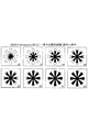
本開示は、一部には、フィルター上での血液の広がりは、スポットされる血液の容積に比例するとの仮説に基づいている。この特性を血液の容積の測定に活用することができる。まず、特定容積の新鮮血を漸増しながら別々のHemaFormフィルター上にスポットし、一晩乾燥させた後に、視覚分析した。図1に、それぞれ異なる既知容積の血液がスポットされた8枚のHemaFormフィルターを図示する。具体的には、スポットされた既知容積の血液は、図1の画像において、左から右に、上から下に増加している。したがって、血液がスポットされたフィルターをざっと目視検査するだけで、フィルター上での血液の広がりが、フィルター上にスポットされた血液の容積に比例することがわかる。これによって、上記の仮説の正しさが確認されたので、次のステップは、血液の広がりを実際に測定することであった。乾燥血液スポットにおける血液の広がりをスポットされた血液の容積に相関させる方法は現在ないため、血液の広がりを定量できる新規な分析ツールを開発する必要があった。 The present disclosure is based in part on the hypothesis that the spread of blood on the filter is proportional to the volume of blood that is spotted. This characteristic can be used for measuring blood volume. First, a specific volume of fresh blood was spotted on separate HemaForm filters with increasing titration, dried overnight, and then visually analyzed. FIG. 1 illustrates eight HemaForm filters each spotted with a different known volume of blood. Specifically, the spotted blood of known volume increases from left to right and from top to bottom in the image of FIG. Therefore, it is understood that the spread of the blood on the filter is proportional to the volume of the blood spotted on the filter only by visual inspection of the filter on which the blood is spotted. This confirmed the correctness of the above hypothesis, so the next step was to actually measure the spread of blood. Since there is currently no way to correlate blood spread in a dried blood spot with the volume of spotted blood, it was necessary to develop a new analytical tool that can quantify blood spread.
我々の方法は、基板(例えば、濾紙)上に投入された血液の容積の一貫したかつ精確な推定を可能にし、実験室以外で採取された血液サンプル中の被験物質の定量に不可欠である。この方法は、本分野において、最小限に侵襲的かつ費用効率的なやり方で血液の採取、保存、及び輸送を可能にする方法であり、他の点では有力な血液サンプリング方法に関する定量化の主要な技術的問題に対処する。 Our method allows a consistent and accurate estimation of the volume of blood input on a substrate (eg filter paper) and is essential for the quantification of test substances in blood samples taken outside the laboratory. This method is a method that allows blood collection, storage, and transportation in the field in a minimally invasive and cost-effective manner, and is the main quantification of the otherwise dominant blood sampling method. To deal with various technical issues.
図2は、本発明の例示的な実施形態のフローチャートであって、血液サンプルの容積を推定するための方法100が提示されている。このフローチャート内のどのようなプロセスの説明又はブロックも、本開示の分野の当業者ならわかるように、このプロセスにおける特定の論理的機能を発揮する一つ又は複数の指示を含む、モジュール、セグメント、コードの一部、又はステップを表すものと理解すべきであって、関係する機能性に基づいて、実質的に同じ順番又は逆の順番を含め、示された又は記述された順番以外でも各機能が発揮される、別の実施法も本開示の範囲に含まれる。
FIG. 2 is a flowchart of an exemplary embodiment of the present invention in which a
図2のブロック102に示されるように、血液のサンプルは、ヒト又は動物の患者から当分野で知られるあらゆる方法で得られる。この方法には、従来からの静脈穿刺法も含まれ、血液が患者の静脈から直接得られる。血液はまた、指先穿刺を介して又は患者身体のあらゆる他の部分を「刺して穴をあける」ことを介しても得ることができる。この方法を介して採取される血液は、通常、皮膚表面近傍の毛細血管からランセット又は類似の装置で皮膚を突き刺すことにより得られる。「指先穿刺」からの血液は、毛細管内に採取され、フィルター上に分注され又は濾紙上に直接スポットされる。
As shown in
図2のブロック104に示されるように、得られた血液のサンプル又は得られた血液のサンプルの一部は、基板上にスポットされる又は他のd方法で置かれる。基板は、血液サンプルを維持できる、当分野で知られるあらゆる材料であることができる。好ましい実施形態において、濾紙を基板として使用できる。Guthrieカード、HemaFormフィルター、その他などの濾紙は、乾燥血液スポットサンプリングにおける使用が当分野において良く知られている。いくつかの実施形態において、基板は、複合材料であることができ及び/又は、例えばシリカで被覆されることができる。
As shown in
図2のブロック106では、配置された血液サンプルの画像が取得される。画像は、好ましくは血液が完全に乾燥した後に、当分野で知られるあらゆる撮像装置を用いて得ることができる。したがって、カメラ、スキャナー、又は他の類似した撮像装置を、開示される方法で成功裏に使用できる。好適な撮像装置の選択には、使いやすさ、多数の画像を得るための固定された台の必要性、多数のフィルターの処理能力、画質、並びに様々な撮像設定及び撮像規制の制御能力及び管理能力等の検討が含まれる。
In
一つの実施形態において、画像を取得ためにカメラを使用することができる。通常、カメラは、カメラを安定に保持すると同時に一貫したかつ再現性のある画像を得るために、三脚又は他の装置に搭載される。別の実施形態において、画像を得るためにスキャナーを使用することができる。例えば、画像を得るために、HP Photosmart(登録商標) 1300又は類似の機器を使用することができる。どのような撮像装置を用いる場合でも、得られる画像の解像度を好ましい解像度又は標準的な解像度に調整することは有益である。例えば、600dpiの解像度を用いることができる。解像度は、以下で説明するように、ソフトウェアを用いて制御し、調整することができる。得られる画像は、コンピューター又は他の電子機器上で閲覧できるように、デジタル形式で提供されることができる。デジタル形式での提供により、さらに、画像編集ソフトウェア又は画像分析ソフトウェアを使用して、画像の閲覧が可能となる。 In one embodiment, a camera can be used to acquire an image. Typically, the camera is mounted on a tripod or other device to keep the camera stable and at the same time obtain consistent and reproducible images. In another embodiment, a scanner can be used to obtain an image. For example, HP Photomart® 1300 or a similar device can be used to obtain an image. Regardless of what imaging device is used, it is beneficial to adjust the resolution of the resulting image to a preferred or standard resolution. For example, a resolution of 600 dpi can be used. The resolution can be controlled and adjusted using software, as described below. The resulting image can be provided in digital form so that it can be viewed on a computer or other electronic device. The provision in digital form further allows viewing of the image using image editing software or image analysis software.
図2のブロック108では、血液サンプルの基板上での被覆率又は被覆面積の近似値を、血液サンプルの画像から決定することができる。この開示の目的のために、血液サンプルの被覆率は、絶対面積に換算して、あるいはパーセント被覆率等の面積比として、測定する又は推定することができる。好ましい実施形態において、被覆率の決定は、画像中の画素をカウントすることで実施可能である。画像中の画素をカウントすることは、好ましくは、画像分析ソフトウェア又は画像編集ソフトウェアを用いて実施される。この目的のための数多くのソフトウェアプログラムが、当分野において知られている(例えば、GIMP2、Adobe Photoshop(登録商標))。
In
画素をカウントするのに先立って、ソフトウェアの様々な設定を調整して、画素をカウントするための最適な画像が得られるようにする必要がある。例えば、画像の解像度を調整することは有益である。全ての画像に一定の解像度を用いることは、精確な結果を確実に得るために有用である。他の最適化も、GIMP2画像分析プログラムによって画素選択のための正しい閾値を選択することで実施可能である。閾値が低いと、非特異的な選択になりやすく、閾値が高いと、画素の色の選択を妨げやすい。 Prior to counting pixels, various software settings need to be adjusted to obtain an optimal image for counting pixels. For example, adjusting the resolution of the image is beneficial. Using a constant resolution for all images is useful to ensure accurate results. Other optimizations can also be performed by selecting the correct threshold for pixel selection by the GIMP2 image analysis program. If the threshold is low, non-specific selection is likely to occur, and if the threshold is high, selection of the pixel color is likely to be hindered.
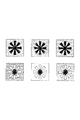
画像における陰影の干渉を最小化するためにも、解像度を最適化することは有益である。基板の外縁に沿って見られる陰影(例えば、HemaFormフィルターの「花弁」に沿った陰影)は、画素を分析する及び画素数を数える際に、画素選択を妨げることがある。あるいは、又はこの目的のために走査ソフトウェアにおける設定の調整に加えて、これらの影響を最小化するため、図3に示すように、画像において様々な背景を用いることができる。 It is also beneficial to optimize the resolution in order to minimize shadow interference in the image. Shading seen along the outer edge of the substrate (eg, shading along the “petals” of the HemaForm filter) may interfere with pixel selection when analyzing pixels and counting pixels. Alternatively, in addition to adjusting settings in the scanning software for this purpose, various backgrounds can be used in the image, as shown in FIG. 3, to minimize these effects.
ソフトウェアを用いて、血液スポットを実際に示す画像の部分に対応する画素だけをカウントすることができる。したがって、血液スポットをカバーする又は少なくとも部分的に重複する画素をカウントすることができる。比較対象の他の画像又はデータに関して整合する限り、個別の画素がカウントされるべきか否かを決定するための他の方法も使用可能である。いくつかの実施形態において、血液スポットに対応する画素の絶対数を用いて、血液スポットの面積を決定することができる。フィルターのブランク領域(すなわち、血液が広がっていないフィルターの部分)の画素もカウントすることができる。得られたブランク領域の画素数から、画素の総数を得て、被覆面積又は被覆率の算出に使用できる、すなわち得られたブランク領域の画素数を血液スポット内でカウントされた画素数に加え、ブランクフィルター全体に対応する画素の既知の数と比較することで、画素のカウントを精確にすることができる。 Software can be used to count only the pixels corresponding to the portion of the image that actually shows the blood spot. Thus, pixels that cover a blood spot or at least partially overlap can be counted. Other methods for determining whether individual pixels should be counted can be used as long as they match with respect to other images or data to be compared. In some embodiments, the absolute number of pixels corresponding to a blood spot can be used to determine the area of the blood spot. Pixels in the blank area of the filter (ie, the portion of the filter where blood is not spread) can also be counted. From the number of pixels of the obtained blank area, the total number of pixels can be obtained and used for calculation of the coverage area or coverage, i.e., the number of pixels of the obtained blank area is added to the number of pixels counted in the blood spot, By comparing with the known number of pixels corresponding to the entire blank filter, the pixel count can be made accurate.
別の実施形態において、例えば、ブランク基板(例えば、フィルター)の画像内のブランク基板の画素をさらにカウントすることで、「パーセント被覆」面積を決定することができる。ブランク基板の画像を血液スポットの画像と同じ設定(例えば、解像度)で取得することは、二つの画像を精確かつ有意義に比較する上で重要である。パーセント被覆率を得るため、血液スポット内でカウントされた画素数のブランクフィルター内でカウントされた画素数に対する比が決定される。 In another embodiment, the “percent coverage” area can be determined, for example, by further counting the blank substrate pixels in the image of the blank substrate (eg, filter). Acquiring a blank substrate image with the same settings (eg, resolution) as the blood spot image is important for accurate and meaningful comparison of the two images. To obtain the percent coverage, the ratio of the number of pixels counted in the blood spot to the number of pixels counted in the blank filter is determined.
図2のブロック110に示されるように、ブロック108で決定された血液スポットの被覆率又は被覆面積を、検量線、表、チャート、又は他のデータと比較して、血液スポットの容積を算出することができる。そのような検量線、表、チャート、又は他のデータには、既知容積の血液サンプルに関するデータが含まれる。例えば、異なる既知容積の一連の血液サンプルが、別々に基板上にスポットされる。スポットされた各血液サンプルの画像が得られ、得られた画像から被覆面積又は被覆率が算出される。その後、これらの算出された被覆面積又は被覆率は、既知容積に対してプロットされるあるいは他の方法で既知容積と比較されて、検量線、表、チャート、等々が得られる。最良適合線を用いると、これらのデータの比較が容易になる。後で得られる血液サンプルについて、血液サンプルの容量の推定値は、血液サンプルのパーセント被覆率を、ブロック110で作成された検量線又は他のデータと比較することにより決定可能である。その精度を確保するため、必要に応じて、検量線のデータを更新することも必要である。また、他の特性、例えばヘマトクリット値による基板上での血液サンプルの広がる面積への推定される影響を補正するため、その特性が異なる既知のサンプルを検量線の作成に用いることが望ましい。
As shown in
実施例1:検量線の作成
以下の例示的方法によって、検量線を作成できる。一連の精確な既知容積の新鮮血を、HemaFormフィルター上にスポットし、一晩乾燥させた。撮像のために、カメラを三脚上に固定した。解像度が最適となるように、カメラの設定を調整し、その設定を維持したまま、全ての画像を撮像した。画像分析プログラムGIMP2を用いて画素数をカウントした。このソフトウェアは、インターネットから自由に入手でき、分析の実施における成功が証明されているため、理想的な選択肢である(ただし、Adobe Photoshop(登録商標)等の他の画像分析プログラムも同様に良好に機能する)。参照用に、ブランクHemaFormフィルターの画像を取得して、その画像から、ブランクフィルターに対応する画素の総数を決定した。乾燥血液スポット内の画素及び乾燥血液スポット周りのフィルターの周囲の空(透明)領域内の画素も、図4に示すように、選択してカウントした。
Example 1: Creation of a calibration curve A calibration curve can be created by the following exemplary method. A series of precise known volumes of fresh blood was spotted on a HemaForm filter and allowed to dry overnight. The camera was fixed on a tripod for imaging. The camera settings were adjusted so that the resolution was optimal, and all images were captured while maintaining the settings. The number of pixels was counted using the image analysis program GIMP2. This software is an ideal choice because it is freely available from the Internet and has proven successful in performing the analysis (but other image analysis programs such as Adobe Photoshop® are equally good) Function). For reference, an image of a blank HemaForm filter was acquired and the total number of pixels corresponding to the blank filter was determined from the image. Pixels in the dry blood spot and pixels in the empty (transparent) area around the filter around the dry blood spot were also selected and counted as shown in FIG.
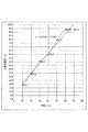
次に、乾燥血液スポット内の画素数をブランクフィルター内の総画素数で割ることにより、画素被覆率を決定した。図5は、画素被覆率対スポット血液容積の結果を示す。図5に示されるように、データポイントに適合する最良適合線の勾配を決定した。図5の最良適合線の精度を確認するために、この最良適合線の勾配から得られる血液サンプルの容積推定値を、実際の既知の容積と比較した。容積推定値は、実際の容積に対して1μL〜5μL以内で、この方法が有効であることを示した。ただし、この分析法をさらに改善することで、より高い精度が得られるはずである。 Next, the pixel coverage was determined by dividing the number of pixels in the dry blood spot by the total number of pixels in the blank filter. FIG. 5 shows the results of pixel coverage versus spot blood volume. As shown in FIG. 5, the slope of the best fit line that fits the data points was determined. To confirm the accuracy of the best fit line in FIG. 5, the estimated volume of the blood sample obtained from the slope of this best fit line was compared to the actual known volume. Volume estimates showed that this method is effective within 1 μL-5 μL of actual volume. However, further improvements in this analytical method should provide higher accuracy.
実施例2:組合せ検量線の作成
以下の例示的方法によって、組合せ検量線を得ることができる。上述の考察に基づいて、スキャナー(例えば、HP Photosmart(登録商標) 3100)を選択した。画素の分析及びカウントの質を改善するために、GIMP2画像分析プログラムによって画像の解像度を最適化した。
Example 2: Creation of a Combination Calibration Curve A combination calibration curve can be obtained by the following exemplary method. Based on the above considerations, a scanner (e.g., HP Photoshop (R) 3100) was selected. In order to improve the quality of pixel analysis and counting, the resolution of the image was optimized by the GIMP2 image analysis program.
血液の広がりの違いの要因を説明するため、年齢、性別、及びヘマトクリット値が異なる、三名からの血液を分析した。三名の対象者からの新鮮血を、異なる既知容積でフィルター上にスポットした。これらのスポット血液サンプルの画像を取得して、画素被覆率の算出に用いた。このデータから、図6及び図7に示すように、三つの異なる検量線を作成した。図8に示す、組合せ検量線も作成して、勾配を決定した。この組合せ検量線は、未知容積のサンプルの容積決定に用いた。 To explain the cause of the difference in blood spread, blood from three people with different age, gender, and hematocrit values was analyzed. Fresh blood from three subjects was spotted on the filter at different known volumes. Images of these spot blood samples were acquired and used to calculate the pixel coverage. From this data, three different calibration curves were created as shown in FIGS. A combination calibration curve shown in FIG. 8 was also created to determine the slope. This combined calibration curve was used to determine the volume of an unknown volume sample.
本明細書に開示の方法を用いる場合、予測精度は非常に高く、推定された容積は、一般に、実際の容積に対して2μL〜3μL又はそれ以下の範囲内である。ヘマトクリット値は、得られる測定値に影響することが認められた。したがって、ヘマトクリット値が非常に低い又は非常に高い場合、算出される容積は、一般に、スポットされた実際の容積の5%以内となる。ヘマトクリット値が低い血液の場合、所定容積内の血漿量が多くなるため、より広がりやすくなる。逆に、ヘマトクリット値が高い血液の場合には、所定容積内の血漿量が少なくなるため、一般に広がりにくくなる。このように、開示される方法を用いて得られる測定値は、血液中の血漿量に直接関係する。また、全血から測定される代謝産物レベルは、疾患の状態又は進行をより精確に示し、血漿から測定される濃度との比較がより安定する。 When using the methods disclosed herein, the prediction accuracy is very high and the estimated volume is generally in the range of 2 μL to 3 μL or less relative to the actual volume. The hematocrit value was found to affect the measured value obtained. Thus, if the hematocrit value is very low or very high, the calculated volume will generally be within 5% of the actual spotted volume. In the case of blood with a low hematocrit value, the amount of plasma in the predetermined volume increases, and therefore it becomes easier to spread. On the contrary, in the case of blood having a high hematocrit value, the amount of plasma in the predetermined volume decreases, so that it is generally difficult to spread. Thus, the measurements obtained using the disclosed method are directly related to the amount of plasma in the blood. In addition, metabolite levels measured from whole blood more accurately indicate disease state or progression and are more stable compared to concentrations measured from plasma.
検量線の精度の検証は、フィルター上に既知容積の血液をスポットすることにより、実施可能である。このような場合、容積分析実施者にその容積が知らされない、盲検が通常実施される。表1は、盲検で分析された、いくつかの容積を有するサンプルを示す。表1からわかるように、全ての容積推定値は、実際の既知容積に対して0.2μL〜3.5μL以内となった。

実施例3:血液の容積を推定する方法
好ましい実施形態において、血液の容積の推定は、以下のように実施可能である。この技術は、DBS画像中の画素の算出に基づく。スポット中の血液の容積は、その画素数を、既知容積のDBSの検量線の画素数と比較することにより、測定される。ステップ毎の手順は、下記の通りである:
ステップ1:画素数の算出
(a)DBSの走査
DBS中の画素をカウントするため、ステップ1は、DBSを走査することである。DBSサンプルは、ブランクフィルター(血液がスポットされていない)と共に、スキャナー上で走査される。走査解像度は、定められた設定値にセットされ、この定められた設定値は、いかなる設定値でも可能であるが、一旦選択されたら、全ての分析に対して同一に維持されなければならない。例えば、600dpiの解像度を用いることができる。
(b)GIMP2画像分析ソフトウェアを用いる画像分析
このソフトウェアは、インターネットから自由に入手できる。走査されたDBSを、選択ツールを用いてトリミングし、画素を実際の血液スポット部とブランク部に分けてカウントする。ブランクフィルターの画素も同様にカウントする。
(c)実際の画素の被覆率
スポット内の画素の割合を、スポット内の画素数のブランクフィルター内の総画素数に対する比を決定することにより、算出する。
ステップ2:検量線の作成
異なる(理想的には異なるヘマトクリット値を有する)個人から、ヘパリン/EDTAチューブ内に血液を採取する。その後、既知容積のDBSを作成するため、5μLから60μLまでの精確な既知容積の採取された新鮮血を、(三つのサンプル)個々にスポットする。一晩乾燥させて、ステップ1に記載のように走査する。画素被覆率を算出し、画素被覆率対容積の検量線を作成する。検量線の勾配を決定する。
ステップ3:DBS中の血液の容積の算出
未知容積のDBSについて、ステップ1に記載のように、画素被覆率を算出し、ステップ2に記載のように決定された勾配に基づいて容積を算出する。
Example 3: Method for Estimating Blood Volume In a preferred embodiment, the estimation of blood volume can be performed as follows. This technique is based on the calculation of pixels in a DBS image. The volume of blood in the spot is measured by comparing the number of pixels with the number of pixels in a calibration curve for a DBS of known volume. The procedure for each step is as follows:
Step 1: Calculation of the number of pixels (a)
(B) Image analysis using GIMP2 image analysis software This software is freely available from the Internet. The scanned DBS is trimmed using a selection tool, and the pixels are divided into an actual blood spot portion and a blank portion and counted. The blank filter pixels are counted in the same manner.
(C) Actual Pixel Coverage Ratio The ratio of pixels in the spot is calculated by determining the ratio of the number of pixels in the spot to the total number of pixels in the blank filter.
Step 2: Creating a calibration curve Blood is drawn into heparin / EDTA tubes from different individuals (ideally with different hematocrit values). Then, to create a known volume of DBS, an accurate known volume of freshly collected blood from 5 μL to 60 μL is spotted individually (three samples). Dry overnight and scan as described in
Step 3: Calculation of blood volume in DBS For DBS of unknown volume, calculate the pixel coverage as described in
プレートリーダー装置
本明細書に開示されるこの装置は、血液サンプルが採取されたフィルター(例えば、DBS)を保持するのに使用できる。好ましい実施形態において、本開示は、多数の血液サンプルの走査又は撮像を、二次汚染することなく、走査に関係する陰影アーチファクトを最小にして、迅速におこなうための装置を提供する。この装置はまた、サンプルを組織的に維持し、走査に備えてサンプルをしっかり保持し、かつ最大限にサンプルをヒト暴露から隔離する便益をも提供する。この装置のさらなる利点には、実質的にいかなるスキャナーにも適合すること、使用が容易であること、及び耐久性があることが含まれる。この装置は、サンプルの間隔及び走査距離を均一に保つことができるため、走査されたサンプルのバッチ毎の相互比較を可能にする。装置これにより、サンプルを精確に同じように走査するようにする、又は、血液サンプルの容積及び他の特性を算出するためのアルゴリズムを調整するための所要時間を大幅に短縮することができる。この装置は、別体の構成要素から構成され、別体の構成要素は、走査のために組立可能で、除染及びサンプル調製のために分離可能である。この装置はまた、ラベル型板を内蔵しており、走査されたサンプルの記録を保持することができるため、走査されたサンプルの記録及び識別を容易にする。
Plate Reader Device This device disclosed herein can be used to hold a filter (eg, DBS) from which a blood sample has been taken. In a preferred embodiment, the present disclosure provides an apparatus for quickly scanning or imaging a large number of blood samples without cross contamination and with minimal shadow artifacts associated with the scan. This device also provides the benefits of maintaining the sample systematically, holding the sample firmly in preparation for scanning, and maximally isolating the sample from human exposure. Additional advantages of this device include compatibility with virtually any scanner, ease of use, and durability. This apparatus can maintain a uniform sample spacing and scan distance, thus allowing a batch-to-batch comparison of scanned samples. Apparatus This can greatly reduce the time required to scan the sample exactly the same, or to adjust the algorithm for calculating the volume and other characteristics of the blood sample. The device is composed of separate components, which can be assembled for scanning and separable for decontamination and sample preparation. The device also incorporates a label template and can hold a record of the scanned sample, thus facilitating the recording and identification of the scanned sample.
他の実施形態において、本開示は、本明細書に開示の全ての方法と共に使用可能な、フィルター上の乾燥血液スポットを走査するための装置を提供する。好ましい実施形態において、この装置は、多数の乾燥血液スポットの同時走査を可能にする。図9〜図15に示すように、この装置は、最大四つの部品を備えることができ、それらを組み立てる又は一緒に配置することができる。 In other embodiments, the present disclosure provides an apparatus for scanning a dry blood spot on a filter that can be used with all the methods disclosed herein. In a preferred embodiment, the device allows simultaneous scanning of multiple dry blood spots. As shown in FIGS. 9-15, the apparatus can comprise up to four parts, which can be assembled or placed together.
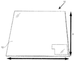
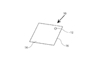
図9〜図10は、この装置の第一の層10の例示的実施形態を示す。第一の層10は、一般に、平坦な又は略平坦な材料から成る。第一の層10は、第一の層10のそれぞれ反対側に、第一の面14及び第二の面16を備えることができる。好ましくは、第一の層10は、均一な厚さである。好ましい実施形態において、第一の層10は、一枚のプレキシガラスのシートから成ることができる。第一の層10は、一つ又は複数の透明部12を備えることができる。一つ又は複数の透明部12は、大きさ、形状、直径等が同一であっても異なっていても良い。透明部12の間隔は、第一の層10の一つ又は複数の寸法において均一であることができる。あるいは、透明部12の間隔は、任意又は不規則でもよい。いくつかの実施形態において、第一の層10は、全体的に透明であることができる。
9-10 show an exemplary embodiment of the
この装置の第二の層20を、図11〜図12に示す。第二の層20は、一般に、平坦な又は略平坦な材料から成る。第二の層20は、第二の層20のそれぞれ反対側に、第一の面24及び第二の面26を備えることができる。好ましくは、第二の層20は、略均一な厚さである。好ましい実施形態において、第二の層20は、一枚のプレキシガラスから成ることができる。一つ又は複数の穴22が、第二の層20に形成される。穴22は、第二の層20を貫通する(すなわち、第一の面24から第二の面26まで延在する)ことができる、あるいは、第二の層20の一部を通って延在することができる。一つ又は複数の穴22は、大きさ、形状、直径等が同じ出会っても異なってもよい。穴22の間隔は、第二の層20の一つ又は複数の寸法において均一であることができる。あるいは、穴22の間隔は、任意又は不規則でもよい。
The
好ましい実施形態において、穴22は、図16に示されるように、各穴が乾燥血液サンプルを受容できるように、十分大きくなければならない。通常、そのような血液サンプルは、濾紙28又は他の類似する基板の上に包含される。したがって、一つ又は複数の穴22のそれぞれは、血液サンプルを包含する濾紙28又は類似する基板が穴内に平坦に置かれるように、十分大きくなければならない。好ましい実施形態において、穴内でのフィルター又は基板のいかなる運動も移動も限定される又は排除されるように、穴の寸法は、フィルター又は基板の寸法に密接に適合する、あるいはフィルター又は基板の寸法よりわずかに大きい。
In a preferred embodiment, the
図13〜図14は、この装置の第三の層30を示す。第三の層30は、一般に、平坦な又は略平坦な材料から成る。第三の層30は、第三の層30のそれぞれ反対側に、第一の表面34及び第二の表面36を備えることができる。好ましくは、第三の層30は、略均一な厚さである。好ましい実施形態において、第三の層30は、一枚のプレキシガラスから成ることができる。第三の層30は、第三の層30の第一の面34から上方に延在する、一つ又は複数の隆起部32を備える。隆起部32は、いかなる大きさ、形状、又は色であっても良い。隆起部32は、第三の層30と一体に形成されることができる、あるいは、当分野で既知の何らかの付着機構を介して第三の層30に取り付けられる、別体の構成要素であることができる。隆起部32は、アクリル、プラスチック、金属等何らかの好適な材料から成ることができる。好ましい実施形態において、隆起部32は、アクリルディスクから構成されることができる。好ましい実施形態において、隆起部32は、第二の層及び第三の層を整列させて積み重ねる際に、各隆起部32が第二の層20内の穴22に嵌合するような、大きさであることができる。
13-14 show the
図15は、この装置と共に使用できる、一つ又は複数のラベル40を示す。一つ又は複数のラベル40は、それぞれ別体であることができ、あるいは、多数のラベルを含む型板42上に含まれることができる。いずれにしても、ラベルは、この装置から除去可能でなければならない。したがって、一つ又は複数のラベルは、又はラベルを含む型板は、この装置の一つ又は複数の層の上に位置する又は載るように構成されることができる。あるいは、一つ又は複数のラベルは、又はラベルを含む型板は、ラベルをこの装置の一つ又は複数の層へのしっかりした固定並びにラベルのこの器具からの除去の双方を可能にする、接着剤を備えることができる。ラベル及び/又はラベルを含む型板は、紙、トランスファープラスチック、厚紙、プレキシガラス等好適な材料から成ることができる。ラベルは、装置内に保持される試料(例えば、血液サンプル、フィルター、基板など)を識別するためのコード44を備えることができる。文字、単語、数字、色、バーコード、マトリックスバーコード、又はそれらの組合せを含む、一種又は複数種のコード44を用いることができる。
FIG. 15 shows one or
好ましい実施形態において、第一の層、第二の層、及び第三の層は、それぞれ、略同様の大きさ及び形状を有する。好ましくは、各層は、標準的なスキャナー又は他の撮像機器と共に使用可能な、大きさである。したがって、いくつかの実施形態において、各層は、タイプ用紙一枚と略同じ長さ及び幅を有することができる。そのような大きさなら、スキャナーの台にこの装置を載せて、この装置内の試料を走査することができる。各層は、同一の材料又は異なる材料から成ることができる。好ましくは、各層は、プレキシガラス又は他のプラスチックから成る。 In a preferred embodiment, the first layer, the second layer, and the third layer each have substantially the same size and shape. Preferably, each layer is sized for use with a standard scanner or other imaging device. Thus, in some embodiments, each layer can have approximately the same length and width as a single sheet of type paper. If it is such a size, this apparatus can be mounted on the stage of a scanner, and the sample in this apparatus can be scanned. Each layer can be made of the same material or different materials. Preferably, each layer consists of plexiglass or other plastic.
各層及びラベルは、図16〜図18に示されるように、組み立てられて装置1を形成するように構成される。組み立てる際に、各層は、各層の長さ及び幅を他の層の長さ及び幅に合わせる、又は、略合わせるように単に整列させて積み重ねることができる。あるいは、各層を、ネジ、ボルト、クギ状物、化学接着剤、テープ、ゴムバンド、又はこれらの組合せなどの取り付け機構によって確実に組み立てられることができる。一つの実施形態において、第三の層30上の隆起部32は、第二の層20内の穴22内にしっかり嵌合して、これらの層がぴったり保持される。組み立てられたものはまた、端をテープでしっかり保持することもできる。
Each layer and label is configured to be assembled to form the
この装置が組み立てられて全ての部品が整列された時、各層の様々な構成要素も互いに整列されなければならない。すなわち、第一の層10の透明部12は、第二の層20の穴22、第三の層30の隆起部32、及びラベル40と整列しなければならない。各層は、一般に、第二の層を第一の層と第三の層との間に介在させて、積み重ねられる。したがって、第三の層30の一つ又は複数の隆起部32はそれぞれ、第二の層20の穴22内に嵌合し、第一の層10の一つ又は複数の透明部12はそれぞれ、穴を挟んで、隆起部が挿入される面とは反対側の面において穴22を覆う。さらに、この装置が組み立てられかつフィルター又は他の基板も穴に挿入された場合(図16に示すように)、隆起部は、穴内でフィルターを保持し、フィルターを第一の層の透明部に対して押し付ける(図18に示されるように)。したがって、隆起部32は、好ましくは、穴の深さ全体に延在し、又は穴の深さほぼ全体に延在する。さらに、隆起部が穴に挿入されることで、第二の層及び第三の層の相対運動が制限され、この装置がしっかりと組み立てられる。
When the device is assembled and all parts are aligned, the various components of each layer must also be aligned with each other. That is, the
組み立てられると、ラベル40、又はラベルを含む型板42は、一般に、図18に示されるように、第三の層に取り付けられる、又は第三の層に隣接して置かれる。しかし、レベル又は型板は、第一の層又は第二の層に取り付けられる、接着される、あるいは第一の層又は第二の層に隣接して置かれることもできる。
When assembled, the
実施例4:装置構成要素の例示的特性
例示的実施形態において、この装置の構成要素は、以下の特性を有することができる。第一の層は、8インチ×11インチの平らなプレキシガラスから成る(図9)。第二の層は、3/4インチの穴が穿設された、8インチ×11インチの平らなプレキシガラスから成る(図11)。第三の層は、第二の層に穿設された3/4インチの穴に対応する3/4インチの着色されたアクリルディスクが取り付けられた、8インチ×11インチの平らなプレキシガラスから成る(図13)。サンプル表示用のラベルは、取り外し可能な型板(紙及び/又はトランスファープラスチックから成る)上に含まれる(図15)。ラベルは、付番方式を有する。
Example 4: Exemplary Characteristics of Device Components In an exemplary embodiment, the device components may have the following characteristics: The first layer consists of 8 "x 11" flat plexiglass (Figure 9). The second layer consists of 8 "x 11" flat plexiglass with 3/4 "holes drilled (Figure 11). The third layer consists of 8 "x 11" flat plexiglass fitted with a 3/4 "colored acrylic disc corresponding to the 3/4" hole drilled in the second layer. (FIG. 13). Sample display labels are included on a removable template (made of paper and / or transfer plastic) (FIG. 15). The label has a numbering system.
実施例5:装置の組立
例示的実施形態において、この装置の構成要素は、以下のように組み立てられる。第一の層と第二の層を、第一の層の透明部が第二の層の穴と一致するように共に取り付けられる(図16)。ブランク濾紙を第二の層の一つの穴に配置し、残りの穴に乾燥血液スポットを含むフィルターを入れる。第三の層とラベル型板を組み合わせ(図17)、各ラベルがフィルター又は血液サンプルと適切に対応するように、第一の層と第二の層の上面に配置する。また、第三の層の隆起部(アクリルディスク)が各穴内で各フィルターを押し下げて、各試料の表面積が100%正確に走査されるようにする。完全に組み立てられた装置(図18)をスキャナー内に配置して、走査する。
Example 5: Device Assembly In an exemplary embodiment, the components of the device are assembled as follows. The first layer and the second layer are attached together so that the transparency of the first layer coincides with the hole in the second layer (FIG. 16). A blank filter paper is placed in one hole of the second layer and a filter containing a dried blood spot is placed in the remaining hole. The third layer and label template are combined (FIG. 17) and placed on top of the first and second layers so that each label corresponds appropriately with a filter or blood sample. Also, the raised portion of the third layer (acrylic disc) pushes down each filter within each hole so that the surface area of each sample is scanned 100% accurately. The fully assembled device (FIG. 18) is placed in the scanner and scanned.
本開示の上記の実施形態、特に「好ましい」実施形態は、単に実施可能な例であり、単に本開示の本質の明確な理解のために記載されていることを強調されなければならない。本開示の趣旨及び本質から実質的に逸脱しない範囲で本開示の上記の実施形態に種々変更及び修正が可能である。そのような修正及び変更の全ては、本明細書において、本開示の範囲及び本開示に含まれるものとされ、以下の請求項によって保護される。 It should be emphasized that the above-described embodiments of the present disclosure, particularly “preferred” embodiments, are merely possible examples, and are described solely for a clear understanding of the nature of the disclosure. Various changes and modifications can be made to the above-described embodiments of the present disclosure without departing from the spirit and essence of the present disclosure. All such modifications and changes are intended to be included herein within the scope of this disclosure and the present disclosure and protected by the following claims.
Claims (15)
前記血液サンプルを基板上にスポットするステップと、
前記血液サンプルの画像を取得するステップと、
前記サンプルの前記画像の被覆率又は被覆面積の近似値を決定するステップと、
前記決定された被覆率又は被覆面積の近似値を検量線と比較して、前記血液サンプルの推定容積を決定するステップと、を備える、
血液サンプルの容積を推定するための方法。 Obtaining a blood sample;
Spotting the blood sample on a substrate;
Obtaining an image of the blood sample;
Determining an approximation of the coverage or area of the image of the sample;
Comparing an approximate value of the determined coverage or area with a calibration curve to determine an estimated volume of the blood sample.
A method for estimating the volume of a blood sample.
(b)前記基板は、紙を含むフィルターから成る特徴、
のうち一つ又は複数を特徴とする、請求項1乃至4のいずれかに記載の方法。 (A) the image of the blood sample is acquired using a scanner or camera; and
(B) the substrate comprises a filter comprising paper;
The method according to claim 1, wherein one or more of the methods are characterized.
一つ又は複数の穴を含む第二の層であって、前記一つ又は複数の穴は、前記第二の層を通って形成され、それぞれの穴は乾燥血液サンプルフィルターを受容する大きさである第二の層と、
一つ又は複数の隆起部を含む第三の層と、を備え、
前記第二の層を前記第一の層と前記第三の層との間に介在させて前記第一、第二、及び第三の層が互いに重なり合うように整列され積み重ねられる際に、前記第一の層の前記一つ又は複数の透明部が、前記第二の層の前記一つ又は複数の穴及び前記第三の層の前記一つ又は複数の隆起部と重なる、
乾燥血液サンプル用のフィルターを走査するための装置。 A first layer comprising one or more transparent parts;
A second layer comprising one or more holes, wherein the one or more holes are formed through the second layer, each hole being sized to receive a dry blood sample filter. With a second layer,
A third layer comprising one or more ridges,
When the second layer is interposed between the first layer and the third layer, the first, second, and third layers are aligned and stacked so as to overlap each other. The one or more transparent portions of one layer overlap the one or more holes of the second layer and the one or more raised portions of the third layer;
A device for scanning a filter for dry blood samples.
(b)前記第一、第二、及び第三の層は、略矩形状であって、略同一の大きさである特徴と、
(c)前記第一の層は、全体として透明である特徴と、
(d)前記第三の層上の前記一つ又は複数の隆起部は、アクリルディスクから構成される特徴、
のうち一つ又は複数を特徴とする、請求項6乃至10のいずれかに記載の装置。 (A) at least one of the first, second, or third layer is made of plexiglass;
(B) the first, second, and third layers are substantially rectangular and have substantially the same size;
(C) the first layer is generally transparent,
(D) the one or more raised portions on the third layer are characterized by comprising an acrylic disc;
11. A device according to any of claims 6 to 10, characterized by one or more of the following.
Applications Claiming Priority (3)
| Application Number | Priority Date | Filing Date | Title |
|---|---|---|---|
| US201562154520P | 2015-04-29 | 2015-04-29 | |
| US62/154,520 | 2015-04-29 | ||
| PCT/US2016/030226 WO2016176629A1 (en) | 2015-04-29 | 2016-04-29 | Methods and devices for quantitating blood samples |
Publications (2)
| Publication Number | Publication Date |
|---|---|
| JP2018514756A true JP2018514756A (en) | 2018-06-07 |
| JP2018514756A5 JP2018514756A5 (en) | 2019-05-30 |
Family
ID=57198751
Family Applications (1)
| Application Number | Title | Priority Date | Filing Date |
|---|---|---|---|
| JP2017548931A Pending JP2018514756A (en) | 2015-04-29 | 2016-04-29 | Method and apparatus for quantifying blood samples |
Country Status (7)
| Country | Link |
|---|---|
| US (1) | US10024842B2 (en) |
| EP (1) | EP3250919A4 (en) |
| JP (1) | JP2018514756A (en) |
| CN (1) | CN107250789A (en) |
| CA (1) | CA2983918A1 (en) |
| HK (1) | HK1245885A1 (en) |
| WO (1) | WO2016176629A1 (en) |
Cited By (1)
| Publication number | Priority date | Publication date | Assignee | Title |
|---|---|---|---|---|
| JP2021514465A (en) * | 2018-02-19 | 2021-06-10 | エフ.ホフマン−ラ ロシュ アーゲーF. Hoffmann−La Roche Aktiengesellschaft | Methods and devices for making analytical measurements |
Families Citing this family (4)
| Publication number | Priority date | Publication date | Assignee | Title |
|---|---|---|---|---|
| US9744155B2 (en) | 2012-03-28 | 2017-08-29 | Ixcela, Inc. | IPA as a therapeutic agent, as a protective agent, and as a biomarker of disease risk |
| US11276228B2 (en) * | 2018-03-22 | 2022-03-15 | 3Shape A/S | 3D scanning with automatic selection of scan strategy |
| JP2022514833A (en) * | 2018-12-19 | 2022-02-16 | ゲンティアン アクティーゼルスカブ | Method for measuring hematocrit value in whole blood sample |
| US11041847B1 (en) | 2019-01-25 | 2021-06-22 | Ixcela, Inc. | Detection and modification of gut microbial population |
Family Cites Families (20)
| Publication number | Priority date | Publication date | Assignee | Title |
|---|---|---|---|---|
| US6006119A (en) * | 1998-02-04 | 1999-12-21 | Polestar Technologies, Inc. | Non-invasive optical measurement of blood hematocrit |
| JP2000175699A (en) * | 1998-12-15 | 2000-06-27 | Fuji Photo Film Co Ltd | Integration type multilayer chemical analytical element and measuring |
| NL1016779C2 (en) * | 2000-12-02 | 2002-06-04 | Cornelis Johannes Maria V Rijn | Mold, method for manufacturing precision products with the aid of a mold, as well as precision products, in particular microsieves and membrane filters, manufactured with such a mold. |
| US20040151637A1 (en) | 2003-01-30 | 2004-08-05 | Davin Bradley Ferguson | Slide mount collection or storage device for biological specimen |
| JP2007298502A (en) | 2006-04-04 | 2007-11-15 | Fujifilm Corp | Filter for separating blood cells |
| CN101578520B (en) * | 2006-10-18 | 2015-09-16 | 哈佛学院院长等 | Based on formed pattern porous medium cross flow and through biometric apparatus, and preparation method thereof and using method |
| US20080102535A1 (en) | 2006-11-01 | 2008-05-01 | Chace Donald H | Measuring thyroxine levels from dried blood samples using mass spectrometry |
| EP2112514A1 (en) * | 2008-04-24 | 2009-10-28 | bioMérieux BV | Method and apparatus for checking the fluid in a pipet tip |
| JP5097658B2 (en) * | 2008-09-17 | 2012-12-12 | アークレイ株式会社 | How to adjust the flow sensor |
| KR101702154B1 (en) * | 2009-03-24 | 2017-02-03 | 유니버시티 오브 시카고 | Device for carrying out a reaction |
| US8748186B2 (en) * | 2009-12-22 | 2014-06-10 | Abbott Laboratories | Method for performing a blood count and determining the morphology of a blood smear |
| US9546935B1 (en) * | 2010-08-25 | 2017-01-17 | Thomas W. Astle | Dried specimen storage slides, systems and methods |
| TWI690594B (en) | 2011-01-21 | 2020-04-11 | 美商賽瑞諾斯Ip有限責任公司 | Systems and methods for sample use maximization |
| US8748176B2 (en) * | 2011-02-09 | 2014-06-10 | The Regents Of The University Of California | Generation of choroid plexus epithelial cells from human embryonic stem cells |
| US8792693B2 (en) | 2011-07-09 | 2014-07-29 | Gauss Surgical | System and method for estimating extracorporeal blood volume in a physical sample |
| CA2842688A1 (en) | 2011-07-22 | 2013-01-31 | Roche Diagnostics Hematology, Inc. | Blood analyzer calibration and assessment |
| US20140368822A1 (en) * | 2011-12-30 | 2014-12-18 | Burbidge Pty Ltd | Media absorbency determination |
| IN2014DN10002A (en) * | 2012-05-14 | 2015-08-14 | Gauss Surgical | |
| US20140276217A1 (en) * | 2013-03-15 | 2014-09-18 | Lars Otto LIEPOLD | Fluid sampling apparatus and method |
| WO2016049628A1 (en) * | 2014-09-26 | 2016-03-31 | Novilytic, LLC | Apparatus for multiplex extraction of biological samples and in-transit preparation of the same |
-
2016
- 2016-04-29 WO PCT/US2016/030226 patent/WO2016176629A1/en active Application Filing
- 2016-04-29 US US15/143,174 patent/US10024842B2/en active Active
- 2016-04-29 JP JP2017548931A patent/JP2018514756A/en active Pending
- 2016-04-29 CN CN201680010242.6A patent/CN107250789A/en active Pending
- 2016-04-29 CA CA2983918A patent/CA2983918A1/en not_active Abandoned
- 2016-04-29 EP EP16787262.1A patent/EP3250919A4/en not_active Withdrawn
-
2018
- 2018-04-18 HK HK18105039.2A patent/HK1245885A1/en unknown
Cited By (2)
| Publication number | Priority date | Publication date | Assignee | Title |
|---|---|---|---|---|
| JP2021514465A (en) * | 2018-02-19 | 2021-06-10 | エフ.ホフマン−ラ ロシュ アーゲーF. Hoffmann−La Roche Aktiengesellschaft | Methods and devices for making analytical measurements |
| JP7209005B2 (en) | 2018-02-19 | 2023-01-19 | エフ.ホフマン-ラ ロシュ アーゲー | Methods and devices for making analytical measurements |
Also Published As
| Publication number | Publication date |
|---|---|
| CN107250789A (en) | 2017-10-13 |
| CA2983918A1 (en) | 2016-11-03 |
| HK1245885A1 (en) | 2018-08-31 |
| EP3250919A4 (en) | 2019-03-06 |
| US20160320367A1 (en) | 2016-11-03 |
| WO2016176629A1 (en) | 2016-11-03 |
| EP3250919A1 (en) | 2017-12-06 |
| US10024842B2 (en) | 2018-07-17 |
Similar Documents
| Publication | Publication Date | Title |
|---|---|---|
| JP2018514756A (en) | Method and apparatus for quantifying blood samples | |
| EP3141903B1 (en) | Methods and devices for improved accuracy of test results | |
| EP2923335B1 (en) | Test strip and methods and apparatus for reading the same | |
| US7364545B2 (en) | Method of measuring bleeding volume | |
| US20120106811A1 (en) | All-In-One Specimen Cup With Optically Readable Results | |
| US20230324378A1 (en) | Bodily fluid testing method | |
| US11035799B2 (en) | Calibration method for reagent card analyzers | |
| CN101438198A (en) | Automated microscope slide read system | |
| US10677807B2 (en) | System and method for sample collection, transport and analysis | |
| CN111247422A (en) | Method and device for performing analytical measurements | |
| EP3359950B1 (en) | Dried blood sample analysis | |
| CN111712706A (en) | Method and device for carrying out analytical measurements | |
| Di Girolamo et al. | Evaluation of point‐of‐care analysers for blood gas and clinical chemistry in Hermann’s tortoises (Testudo hermanni) | |
| US20180355402A1 (en) | Diagnostic strip for determining the amount of sarcosine, creatinine and hydrogen peroxide in a biological or environmental sample | |
| Fisher et al. | Measurement of clozapine, norclozapine, and amisulpride in plasma and in oral fluid obtained using 2 different sampling systems | |
| US20210035663A1 (en) | Facility and method for validating the origin and/or quality of biological specimen sections | |
| DE202015104611U1 (en) | Test strip cover | |
| EP4111173B1 (en) | Reader for analysing fluorescent markers | |
| US20040019433A1 (en) | Method for locating areas of interest of a substrate | |
| RU2777489C2 (en) | Methods and devices for analytical measurement | |
| RU2786271C2 (en) | Method and devices for analytical measurement | |
| KR20230049094A (en) | Test strip fixture for optical measurement of analytes | |
| WO2016024103A1 (en) | Test target | |
| ATE535795T1 (en) | METHOD FOR EXAMINING A TISSUE SAMPLE |
Legal Events
| Date | Code | Title | Description |
|---|---|---|---|
| A521 | Request for written amendment filed |
Free format text: JAPANESE INTERMEDIATE CODE: A523 Effective date: 20190419 |
|
| A621 | Written request for application examination |
Free format text: JAPANESE INTERMEDIATE CODE: A621 Effective date: 20190419 |
|
| A131 | Notification of reasons for refusal |
Free format text: JAPANESE INTERMEDIATE CODE: A131 Effective date: 20200204 |
|
| A977 | Report on retrieval |
Free format text: JAPANESE INTERMEDIATE CODE: A971007 Effective date: 20200131 |
|
| A02 | Decision of refusal |
Free format text: JAPANESE INTERMEDIATE CODE: A02 Effective date: 20201006 |