JP2018514475A - Packaging machinery - Google Patents
Packaging machinery Download PDFInfo
- Publication number
- JP2018514475A JP2018514475A JP2017557464A JP2017557464A JP2018514475A JP 2018514475 A JP2018514475 A JP 2018514475A JP 2017557464 A JP2017557464 A JP 2017557464A JP 2017557464 A JP2017557464 A JP 2017557464A JP 2018514475 A JP2018514475 A JP 2018514475A
- Authority
- JP
- Japan
- Prior art keywords
- bag
- grippers
- pair
- opening
- engagement device
- Prior art date
- Legal status (The legal status is an assumption and is not a legal conclusion. Google has not performed a legal analysis and makes no representation as to the accuracy of the status listed.)
- Withdrawn
Links
Images


Classifications
-
- B—PERFORMING OPERATIONS; TRANSPORTING
- B65—CONVEYING; PACKING; STORING; HANDLING THIN OR FILAMENTARY MATERIAL
- B65B—MACHINES, APPARATUS OR DEVICES FOR, OR METHODS OF, PACKAGING ARTICLES OR MATERIALS; UNPACKING
- B65B43/00—Forming, feeding, opening or setting-up containers or receptacles in association with packaging
- B65B43/26—Opening or distending bags; Opening, erecting, or setting-up boxes, cartons, or carton blanks
- B65B43/267—Opening of bags interconnected in a web
-
- B—PERFORMING OPERATIONS; TRANSPORTING
- B65—CONVEYING; PACKING; STORING; HANDLING THIN OR FILAMENTARY MATERIAL
- B65B—MACHINES, APPARATUS OR DEVICES FOR, OR METHODS OF, PACKAGING ARTICLES OR MATERIALS; UNPACKING
- B65B5/00—Packaging individual articles in containers or receptacles, e.g. bags, sacks, boxes, cartons, cans, jars
- B65B5/04—Packaging single articles
- B65B5/045—Packaging single articles in bags
-
- B—PERFORMING OPERATIONS; TRANSPORTING
- B65—CONVEYING; PACKING; STORING; HANDLING THIN OR FILAMENTARY MATERIAL
- B65B—MACHINES, APPARATUS OR DEVICES FOR, OR METHODS OF, PACKAGING ARTICLES OR MATERIALS; UNPACKING
- B65B51/00—Devices for, or methods of, sealing or securing package folds or closures; Devices for gathering or twisting wrappers, or necks of bags
- B65B51/10—Applying or generating heat or pressure or combinations thereof
- B65B51/14—Applying or generating heat or pressure or combinations thereof by reciprocating or oscillating members
- B65B51/146—Closing bags
-
- B—PERFORMING OPERATIONS; TRANSPORTING
- B65—CONVEYING; PACKING; STORING; HANDLING THIN OR FILAMENTARY MATERIAL
- B65B—MACHINES, APPARATUS OR DEVICES FOR, OR METHODS OF, PACKAGING ARTICLES OR MATERIALS; UNPACKING
- B65B7/00—Closing containers or receptacles after filling
- B65B7/02—Closing containers or receptacles deformed by, or taking-up shape, of, contents, e.g. bags, sacks
Abstract
パッケージを作製する例示的方法は、接続されたバッグのウェブをバッグの開口部が係合デバイスより下にある位置まで前進させることと、係合デバイスを開放することとを含む。加えて、本例示的方法は、部分的に開放された構成になるまでバッグの開口部に送風することと、係合デバイスの一部がバッグの内側に配置され、係合デバイスの一部がバッグの外側に配置されるように、接続されたバッグのウェブを逆送りすることとを含む。続いて、本例示的方法は、係合デバイスがバッグに係合するように、係合デバイスを閉鎖することと、係合デバイスをバッグの開口部が長方形形状を有することをもたらす位置に移動させることとを含む。An exemplary method of making a package includes advancing a connected bag web to a position where the bag opening is below the engagement device and releasing the engagement device. In addition, the exemplary method includes blowing to the opening of the bag until a partially open configuration, a portion of the engagement device is disposed inside the bag, and a portion of the engagement device is Reverse feeding the webs of connected bags to be placed outside the bag. Subsequently, the present exemplary method closes the engagement device and moves the engagement device to a position that results in the opening of the bag having a rectangular shape such that the engagement device engages the bag. Including.
Description
本願は、米国仮特許出願第62/156,381号(2015年5月4日出願、名称「PACKAGING MACHINE」)の利益を主張し、上記出願の全開示は、参照により本明細書に組み込まれる。 This application claims the benefit of US Provisional Patent Application No. 62 / 156,381 (filed May 4, 2015, entitled “PACKAGING MACHINE”), the entire disclosure of which is incorporated herein by reference. .
Flexible Container Stripsと題されたHershey Lernerに対して1966年6月7日に発行された米国特許第3,254,828号(特許文献1)は、いわゆるロール上のバッグ(ここでは、AutoBag特許と称する)を対象とする。米国特許第3,254,828号は、参照することによってその全体として本明細書に組み込まれる。この特許は、好ましくは、ミシン目の形態における易壊線によって相互接続されたバッグのウェブを開示し、バッグの各々は、片面において開放されている。使用時、バッグは、装填ステーションに連続して給送される。装填ステーションに来ると、各バッグは、風で開放され、製品が挿入され、その後、ウェブから分離され、所望に応じて、バッグは、次いで、シールされ、パッケージを形成する。 U.S. Pat. No. 3,254,828 issued on June 7, 1966 to Hershey Lerner entitled Flexible Container Strips is a so-called bag on a roll (here, the AutoBag patent and The target). U.S. Pat. No. 3,254,828 is hereby incorporated by reference in its entirety. This patent discloses a web of bags, preferably interconnected by frangible lines in the form of perforations, each of the bags being open on one side. In use, the bag is continuously fed to the loading station. Upon arrival at the loading station, each bag is opened with the wind, the product is inserted and then separated from the web, and if desired, the bag is then sealed to form a package.
一連の予開放されたバッグの形態におけるこれらの容器用包材は、AutoBag特許において教示されるようなロール上で供給されるか、またはMethod and Apparatus for Packagingと題されたBernard Lerner、他に対して1980年5月6日に発行された米国特許第4,201,029号(特許文献2)(ここでは、Wig−Wag特許と称する)において教示されるような様式でカートンにおいて連ねられるかのいずれかである。そのような容器用包材は、商標名AutoBag下で本願の譲受人であるAutomated Packaging System,Inc.(Streetsboro,Ohio)によって販売されており、多大な商業的成功を収めている。 These container wraps in the form of a series of pre-opened bags are supplied on a roll as taught in the AutoBag patent or to Bernard Lerner, et al. Entitled Method and Apparatus for Packaging In a carton in the manner as taught in US Pat. No. 4,201,029 issued May 6, 1980 (herein referred to as the Wig-Wag patent). Either. Such container wrappings are available from Automated Packaging System, Inc., the assignee of the present application under the trade name AutoBag. Sold by (Streetsboro, Ohio) with great commercial success.
パッケージを作製する例示的方法は、接続されたバッグのウェブをバッグの開口部が係合デバイスより下にある位置まで前進させることと、係合デバイスを開放することとを含む。加えて、例示的方法は、部分的に開放された構成になるまでバッグの開口部に送風することと、係合デバイスの一部がバッグの内側に配置され、係合デバイスの一部がバッグの外側に配置されるように、接続されたバッグのウェブを逆送りすることとを含む。続いて、例示的方法は、係合デバイスがバッグに係合するように、係合デバイスを閉鎖することと、係合デバイスをバッグの開口部が長方形形状有することをもたらす位置に移動させることとを含む。 An exemplary method of making a package includes advancing a connected bag web to a position where the bag opening is below the engagement device and releasing the engagement device. In addition, the exemplary method includes blowing to the opening of the bag until in a partially open configuration, a portion of the engagement device is disposed inside the bag, and a portion of the engagement device is the bag. Reversing the web of connected bags so as to be located outside the bag. Subsequently, the exemplary method closes the engagement device such that the engagement device engages the bag and moves the engagement device to a position that results in the bag opening having a rectangular shape. including.
別のパッケージを作製する例示的方法は、接続されたバッグのウェブをバッグの開口部が複数の対のグリッパより下にある位置まで前進させることと、各対のグリッパを開放することとを含む。加えて、例示的方法は、部分的に開放された構成になるまでバッグの開口部に送風することと、対のグリッパの各々のうちの1つのグリッパがバッグの内側に配置されるように、接続されたバッグのウェブを逆送りすることとを含む。続いて、例示的方法は、対のグリッパがバッグに係合するように、対のグリッパの各々を閉鎖することと、対のグリッパのうちの少なくとも1つをバッグの開口部が長方形形状有することをもたらす位置まで移動させることとを含む。 An exemplary method of making another package includes advancing the connected bag web to a position where the bag openings are below the plurality of pairs of grippers and opening each pair of grippers. . In addition, the exemplary method includes blowing to the opening of the bag until in a partially open configuration, such that one gripper of each of the pair of grippers is positioned inside the bag. Reversing the web of connected bags. Subsequently, the exemplary method closes each of the pair of grippers so that the pair of grippers engage the bag, and at least one of the pair of grippers has a rectangular opening in the bag. Moving to a position that provides
例示的パッケージを作製するための装置は、送り出し機構と、送風機と、係合デバイスと、シール部材とを含む。送り出し機構は、接続されたバッグのウェブを受け取るように構成される。送風機は、空気をバッグの開口部の中に吹きつけるように構成される。係合デバイスは、第1の対のグリッパと、第2の対のグリッパと、第3の対のグリッパと、第4の対のグリッパとを有する。第2の対のグリッパは、第1の対のグリッパから間隔を置かれ、第3の対および第4の対のグリッパは、互いに対して移動可能である。第1、第2、第3、および第4の対のグリッパの各々は、開放位置と閉鎖位置との両方に移動可能である。シール部材は、バッグの開口部をシールするように構成される。 An apparatus for making an exemplary package includes a delivery mechanism, a blower, an engagement device, and a seal member. The delivery mechanism is configured to receive a web of connected bags. The blower is configured to blow air into the opening of the bag. The engagement device has a first pair of grippers, a second pair of grippers, a third pair of grippers, and a fourth pair of grippers. The second pair of grippers is spaced from the first pair of grippers, and the third and fourth pairs of grippers are movable relative to each other. Each of the first, second, third, and fourth pairs of grippers is movable in both an open position and a closed position. The seal member is configured to seal the opening of the bag.
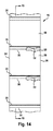
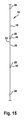
本願は、予成形され相互接続されたバッグ18の細長いウェブ16(図14および15)に関する。例示的実施形態では、ウェブ16は、第1の層20内に画定された開口部30と、第2の層22内の分離線32とを有する。予成形され相互接続されたバッグ18のウェブ16は、様々な異なる形態をとることができる。図14−15によって図示される例示的実施形態では、各予成形されたバッグ18は、ウェブ16の第1および第2の層20、22によって画定される。ウェブの第1および第2の側縁24、26は、第1および第2の層を密閉して接合する。予成形されたシール28が、第1および第2の側縁24、26間に延びている。開口部30は、第1および第2の側縁24、26間に延びている。第2の層22におけるミシン目線等の分離線32は、第1および第2の側縁24、26間に延びている。一例示的実施形態では、開口部30は、ミシン目線32を覆って重ねられる。別の例示的実施形態では、開口部30およびミシン目線32は、オフセットされる。
The present application relates to an elongated web 16 (FIGS. 14 and 15) of a pre-formed and
図14および15によって図示される予成形されたバッグ18のウェブ16は、使用され得る様々な異なるウェブの一例である。予成形され相互接続されたバッグの容認可能ウェブの例として、限定ではないが、H.Lernerに対する米国特許第3,254,828号およびB.Lerner、他に対する米国特許第5,957,824号に開示されるウェブが挙げられ、参照することによってその全体として本明細書に組み込まれる。
The
ウェブ16は、任意の好適な材料から形成され得る。好適な材料の例として、限定ではないが、プラスチック材料、ポリエチレン、セロハン、ビニルフィルム、プリオフィルム、酢酸セルロースフィルム、ポリスチレン、ポリプロピレン、および任意の熱シール可能材料が挙げられる。
The
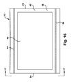
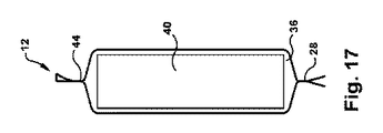
図16および17を参照すると、例示的パッケージ12は、シールされたコンパートメント36を含む。パッケージ12は、任意の数のコンパートメントを有し得る。製品40が、コンパートメント36内に配置される。図示される製品40は、箱である。しかしながら、パッケージ12は、任意の製品を含み得る。コンパートメントは、第1および第2の側縁24、26と、予成形されたシール28と、製品40がバッグの中に装填された後に形成されるシール44とによって画定される。実施例では、シール44は、第1の側縁24から第2の側縁26まで延び、コンパートメント36を密閉してシールする。別の実施形態では、分割シール28は、第1の側縁から第2の側縁まで延びていないこともあり、または、それは、コンパートメント44と外気もしくはコンパートメント44とパッケージの別の随意のコンパートメントとの間の連通を可能にするために断続的であり得る。相互接続されたバッグ16のウェブ18は、様々な異なる方法で作製されることができる。
With reference to FIGS. 16 and 17, the
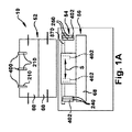
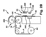
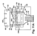
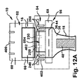
相互接続されたバッグ16のウェブ18は、様々な異なる用途において使用されることができる。例えば、相互接続されたバッグ16のウェブ18は、様々な異なる包装機械において使用されることができる。図1A−1Cは、図14および15によって図示されるバッグ18の細長いウェブ16等、予成形され相互接続されたバッグ18の細長いウェブ16からパッケージ12を作製するための装置10または包装機械の例示的実施形態を図示する。
The
図1A−1Cから13A−13Cは、予成形され相互接続されたバッグ18の細長いウェブ16からパッケージ12を作製するために動作させられる機械の実施例を図式的に図示する。1A−1Cから13A−13Cの略図によって表される任意の装置が、図1A−1Cから13A−13Cによって示される機能を行うように使用されることができる。装置10の概念は、様々な包装機械のいずれかにおいて実装されることができる。例えば、H.Lernerに対する米国特許第3,254,468号、Gereby、他に対する米国特許第4,928,455号、Kramerに対する米国特許第5,341,625号、B.Lerner、他に対する米国特許第5,394,676号、Cronauer、他に対する米国特許第6,543,201号、米国特許第6,742,317号、米国特許第5,394,676号、米国特許第5,371,521号、および米国特許第4,899,520号は、パッケージを予成形され相互接続されたバッグの細長いウェブから作製するために本発明に従って修正され得る包装機械を開示しており、全参照することによってその全体として本明細書に組み込まれる。
1A-1C through 13A-13C schematically illustrate an embodiment of a machine that is operated to make a
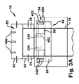
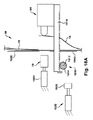
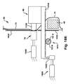
ここで図1A−1Cを参照すると、図示される装置10は、予成形され相互接続されたバッグ18の細長いウェブ16の供給源50(図2B)と、送り出し機構52と、開放配列54と、シール配列56と、コントローラ(図示せず)とを含む。供給源50は、比較的に大量のウェブを比較的に小空間内に備え付けるためにロール化または折り畳まれた細長いウェブ16を備えている。ウェブ16は、供給源50から進行経路Pに沿って送り出し機構52まで経路指定される。送り出し機構52は、ウェブ16を供給源から受け取り、ウェブを進行経路Pに沿って移動させる。送り出し機構52は、様々な異なる形態をとり得る。例えば、ウェブのバッグを進行経路に沿った選択された位置に送り出すように制御され得る、任意の送り出し機構が、使用され得る。図示される実施例では、送り出し機構は、ウェブ16に係合するニップ(nip)を形成する一対のローラ60を備えている。ローラ60は、モータ(図示せず)によって選択的に駆動され、ウェブのバッグを進行経路Pに沿って選択された位置に送り出す。
Referring now to FIGS. 1A-1C, the illustrated
図1A−1Cを参照すると、開放配列54が、進行経路Pに沿って位置付けられ、装填およびシールされるべき各バッグを開放する。図示される実施形態では、開放配列54は、随意の送風機400と、係合デバイス402とを備えている。しかしながら、開放配列54は、様々な異なる形態をとり得る。随意の送風機400は、様々な異なる形態をとることができる。図示される実施形態では、送風機400は、送り出し機構52のローラ60の上方に位置付けられる複数のノズル210を備えている。図示されるノズル210は、下向きに向けられ、ウェブ18の進行経路Pに沿って、ローラ60を越えて下向きに空気を吹きつける。
Referring to FIGS. 1A-1C, an
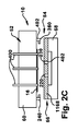
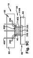
係合デバイス402は、様々な異なる形態をとることができる。図示される実施形態では、係合デバイス402は、第1の対のグリッパ220と、第2の対のグリッパ230とを備えている。第1の対のグリッパ220は、第2の対のグリッパ230から間隔を置かれ、両方とも、バッグ16の第1の層20を把持するように構成される。一例示的実施形態では、グリッパ220、230間の間隔S(図1A)は、調節可能である。この随意の間隔は、自動であり、コントローラによって制御され得るか、または間隔は、手動で調節され得る。これは、係合デバイスが、異なる幅を有する開口部800(図8参照)を提供することを可能にする。
The
係合デバイス402はまた、第3の対のグリッパ240と、第4の対のグリッパ250とを含む。第3の対のグリッパ240および第4の対のグリッパ250は、互いに対して移動可能であり、バッグ18の側縁24、26を把持するように構成される。第3および第4の対のグリッパ240、250は、図11B、12B、ならびに13Bから省略され、第1および第2の対のグリッパ220、230の開口部をより明確に図示する。
The
グリッパ220および230は、以下により詳細に説明されるように、開口部30を把持し、移動し、長方形開口部800を生成する。この長方形開口部は、箱のような長方形アイテム等の大きなアイテムがバッグ18の内側に包装されることを可能にする。
The
図1A−1Cを参照すると、コントローラは、送り出し配列52、開放配列54、およびシール配列56と通信する。コントローラは、送り出し配列52、開放配列54、およびシール配列56を制御し、予成形されたバッグ18をパッケージ12に変換する。様々なコントローラが、本明細書に説明されるような送り出し配列52、開放配列54、およびシール配列56を制御するために使用され、プログラムされることができる。例えば、Kramerに対する米国特許第5,341,625号に説明されるコントローラおよびコントローラアルゴリズムが、送り出し配列52、開放配列54、およびシール配列56を制御し、パッケージを形成するために修正されることができる。
Referring to FIGS. 1A-1C, the controller communicates with a
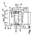
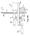
図2A−2Cおよび3A−3Cを参照すると、コントローラは、例示的実施形態では、バッグ18の開口部30が係合デバイス402の直下に来るまで、矢印Pによって示されるように、進行経路に沿ってウェブ16を順方向に送り出すように送り出し機構52を制御する。代替実施形態では、開口部30は、他の位置に送り出される。例えば、開口部30は、送風機400が開口部30を開放または少なくとも部分的に開放するように送風することができる任意の位置に送り出されることができる。例えば、開口部30は、最初に、係合デバイス402の上方に位置付けられ、送風機400によって開放するように送風され、次いで、図3A−3Cによって図示される位置に移動させられ得る。
Referring to FIGS. 2A-2C and 3A-3C, the controller, in the exemplary embodiment, follows the path of travel as indicated by arrow P until the
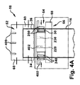
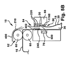
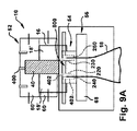
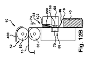
例示的実施形態では、コントローラは、開口部30が係合デバイス402の下方に位置付けられると、グリッパ220、230、240、250を閉鎖位置(図3A−3C参照)から開放位置(図4A−4C参照)に移動させるように係合デバイスを制御する。図5A−5Cを参照すると、コントローラは、バッグの開口部30において、層20、22間に空気を吹きつけるように送風機400を制御する。空気は、開口部30を通して層間に押し進められ、バッグ18を膨らませる。例示的実施形態では、膨らませられたバッグ18の第1の層20は、各対の開放グリッパ220、230の把持部材間の間隙500(図5B参照)と略整列または整列させられる。例示的実施形態では、膨らませられたバッグ18の縁は、各開放対のグリッパ240、250の把持部材間の間隙520(図5Aおよび5C参照)と略整列または整列させられる。
In the exemplary embodiment, the controller moves the
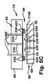
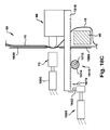
図6A−6Cを参照すると、例示的実施形態では、コントローラ58は、対のグリッパ220、230が開放されている間、送り出し機構52に、矢印612によって示されるように、ウェブを逆送りさせる。送風機400は、随意に、逆送りの間、停止され得る。逆送りは、バッグ18の第1の層20を各対の開放グリッパ220、230の把持部材間の間隙500の中に引き込む。逆送りはまた、バッグ18の縁24、26を各対の開放グリッパ240、250の把持部材間の間隙520の中に引き込む。
6A-6C, in the exemplary embodiment, controller 58 causes
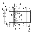
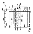
図7A−7Cを参照すると、例示的実施形態では、コントローラ58は、対のグリッパ220、230、240、250に開放位置から閉鎖位置に移動させる。バッグ18の第1の層20は、対のグリッパ220、230の各々の把持部材間に把持される。バッグ18の縁24、26は、各対のグリッパ240、250の把持部材間に把持される。
7A-7C, in the exemplary embodiment, controller 58 causes pair of
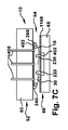
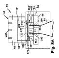
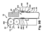
図8A−8Cを参照すると、各バッグ18は、バッグが製品40を装填される位置において、長方形開口部800を提供される。図8A−8Cを参照すると、例示的実施形態では、コントローラは、バッグ18に装填するための長方形開口部800を提供するように係合デバイス402を制御する。図示される実施形態では、対の把持部材220、230は、矢印850によって示されるように、第1の層20を第2の層22から離れるように移動させる(図8Bおよび8C参照)。同時に、対の把持部材240、250は、矢印860によって示されるように、縁24、26を互いに向かって移動させる(図8Aおよび8C参照)。対の把持部材240、250の移動は、第2の層22内のミシン目線32を引き裂く。したがって、バッグ18の縁部分852は、次のバッグ18’の縁部分852’から引き裂かれ、長方形開口部800が形成されることを可能にする。一例示的実施形態では、第2の層22は、対の把持部材240、250が図7A−7Cによって図示される位置から図8A−8Cによって図示される位置に移動するにつれて、対の把持部材240、250間をスライドする。バッグ18の第2の層22内のミシン目32の線の中心部分854は、無傷のままである。これは、バッグ18が長方形開口部800を有する間、バッグ18をバッグ18’に接続されたまま残す。長方形開口部800は、少なくとも6インチ×6インチである。ある実施形態では、長方形開口部800は、6インチ×6インチ、9インチ×9インチ、12インチ×12インチ、18インチ×18インチ、または任意のそれらの組み合わせであり得る。
Referring to FIGS. 8A-8C, each
対の把持部材220、230は、様々な異なる方法において、第1の層20を第2の層22から離れるように移動させることができる。図示される実施形態では、対の把持部材220、230は、シールアセンブリ56の一部であるバー68に取り付けられる。本実施形態では、バー68は、取り付けられた対の把持部材220、230を移動させる。しかしながら、対の把持部材220、230は、バー68と別個のアクチュエータによって移動させられることもできる。対の把持部材240、250は、種々の異なる方法において、縁24、26を互いに向かって移動させることができる。図示される実施形態では、対の把持部材240、250は、装置10の筐体内のスロット870の中を移動する。対の把持部材240、250は、モータ、線形アクチュエータ、または任意の他の機構によって駆動されることができる。
The pair of gripping
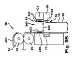
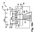
図9A−9Cおよび10A−10Cを参照すると、バッグ18は、装填される位置において長方形開口部800を伴って維持され、製品40が、バッグ18の中に装填される。製品は、手動で、または自動的に、装填され得るか。図示される実施形態では、バッグ18が装填される位置はまた、長方形開口部800が閉鎖された後、バッグ18がシールされる位置でもある。別の実施形態では、バッグが装填される位置は、バッグがシールされる位置と異なる。本実施形態では、コントローラは、バッグが製品40を装填され、閉鎖された後、送り出し機構52に、バッグ18をシール位置に移動させる。
With reference to FIGS. 9A-9C and 10A-10C, the
例示的実施形態では、製品がバッグ18内に装填されると、オペレータは、装填が完了したことを示す信号をコントローラに提供し得る、または装填の完了が、自動的に検出され得る。装置10は、オペレータが、装填完了信号をコントローラに様々な異なる方法で提供することを可能にするように構成され得る。例えば、装置は、制御フットペダル(図示せず)を有し得、または、シール配列56は、オペレータが、装填が完了し、パッケージをシールする時間であることを示すためにオンにすることができる部分を有し得る。同様に、装置は、装填完了を自動的に検出し、コントローラに、この事実を示す信号を提供するように構成されることができる。例えば、装置は、カウンタを含み得るか、またはパッケージを計量し、装填完了を検出し得る。
In an exemplary embodiment, when a product is loaded into the
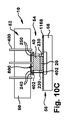
図11A−l1Cを参照すると、オペレータからの信号または装填完了の検出がコントローラに通信され、それは、係合デバイス402にバッグを閉鎖させる。図示される実施形態では、対の把持部材220、230は、矢印1150によって示されるように、第1の層20を第2の層22に向かって戻るように移動させる(図11Bおよび11C参照)。同時に、対の把持部材240、250は、矢印1160によって示されるように、縁24、26を互いから離れるように移動させ、バッグ開口部30を閉鎖する(図11C参照)。例示的実施形態では、第2の層22は、対の把持部材240、250が図10A−10Cによって図示される位置から図11A−11Cによって図示される位置に移動するにつれて、対の把持部材240、250の各々を通ってスライドする。図示される実施形態では、バッグ18の第2の層22内のミシン目線32の中心部分854は、無傷のままである。したがって、閉鎖されたバッグ18は、バッグ18’に接続されたままである。
Referring to FIGS. 11A-11C, a signal from the operator or detection of completion of loading is communicated to the controller, which causes the
依然として、図11A−11Cを参照すると、バッグは、図11A−11Cによって図示される位置においてシールされ得るか、または係合デバイス402は、バッグを解放し得、バッグは、シールするために、別の位置に送り出され得る。一例示的実施形態では、バッグは、係合デバイス402が閉鎖されたバッグ18を保持している間にシールされる。シール配列56は、進行経路Pに沿って位置付けられ、シール44を提供する。シール配列56は、様々な異なる形態をとり得る。例えば、熱をウェブに印加し、第1および第2のウェブを一緒にシールし、シール44を形成する任意の機構が、実装され得る。
Still referring to FIGS. 11A-11C, the bag can be sealed in the position illustrated by FIGS. 11A-11C, or the
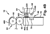
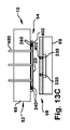
図示される実施形態では、シール配列は、係合および係合解除状態に選択的に移動させられるシール裏当てバー68と加熱要素70とを備えている。図11Bを参照すると、ウェブがシール位置にあるとき、コントローラは、ウェブ16をシール裏当てバー68と加熱要素70との間に締め付けるようにシール配列56を制御する。例示的実施形態では、シール裏当てバー68は、ゴムシール裏当て要素1168を備えている。シール裏当てバー68は、ゴムシール裏当て要素1168と加熱要素70との間にあり得る指を傷つけ得る力より低い力等の低力下、非締め付け位置(図10B参照)から締め付け位置(図11B参照)に移動させられ得る。加えて、ゴムシール裏当て要素1168は、加熱されない。
In the illustrated embodiment, the seal arrangement includes a
例示的実施形態では、加熱要素70は、非締め付け位置(図10B参照)から締め付け位置(図11B参照)に移動させられ、および/または、熱は、ゴムシール裏当て要素1168が締め付け位置に移動させられた後のみ、加熱要素70に加えられる。熱が、ウェブに加えられ、ウェブの層をともに第1の側縁24と第2の側縁26との間でシールする。加熱要素70は、持続的にオンであり得る(すなわち、機械がオンであるとき、常時、高温である)、または加熱要素70は、バッグ18が締め付けられ、および/またはシール信号がコントローラによって提供されるときのみ、熱を加えるように制御され得る。第1および第2の層20、22は、一緒にシールされ、コンパートメント36を形成する。
In the exemplary embodiment,
図18A−18Eは、係合および係合解除状態に選択的に移動させられるシール裏当てバー68ならびに加熱要素70を備えているシールアセンブリ56の例示的実施形態を図示する。例示的実施形態では、加熱要素70は、空気圧アクチュエータまたはソレノイドアクチュエータ等のアクチュエータ1800によって移動させられる。図示されるシール裏当てバー68は、低力アクチュエータ1810によって移動させられ、締め付けアクチュエータ1820によって、定位置に保持される。
18A-18E illustrate an exemplary embodiment of a
低力アクチュエータ1810は、様々な異なる形態をとることができる。一例示的実施形態では、低力アクチュエータ1810は、サーボモータ1812を備えている。図示される実施形態では、サーボモータ1812は、ギヤラック1816を駆動するピニオンギヤ1814を駆動する。しかしながら、任意の駆動配列が、採用されることができる。例示的実施形態では、低力アクチュエータは、シール裏当てバー68と機械の正面パネル1850との間にあり得る人の指を傷つけ得る力を下回る力等の低力を加える。
The
締め付けアクチュエータ1820は、様々な異なる形態をとることができる。一例示的実施形態では、締め付けアクチュエータ1820は、空気圧アクチュエータまたはソレノイドアクチュエータである。任意のタイプのアクチュエータが、使用されることができる。図示される実施形態では、締め付けアクチュエータ1820は、締め付けアクチュエータ1820を低力アクチュエータ1810に選択的に結合し、締め付けアクチュエータ1820を低力アクチュエータ1810から分断するために、ラッチ部材1822を含む。
The clamping
図18Aは、開放または装填位置におけるシールアセンブリ56を図示する。開放または装填位置では、低力アクチュエータ1810は、シール裏当てバー68を機械10の正面パネル1850と間隔を置かれた関係に位置付ける。この位置では、アクチュエータ1800は、加熱要素70を正面パネル1850に対して嵌め込み関係に位置付ける。これは、ユーザが加熱要素に不注意に触れることを防止する。図18Bにおける矢印1860は、低力アクチュエータ1810がシール裏当てバー68を係合またはシール位置に移動させることを図示する。図18Cにおける矢印1870は、締め付けアクチュエータ1820のラッチ部材1822が結合位置に移動することを図示する。図18Dにおける矢印1880は、締め付けアクチュエータ1820が低力アクチュエータ1810に結合し、低力アクチュエータ1810を締め付け位置に保持することを図示する。
FIG. 18A illustrates the
図18Eにおける矢印1890は、加熱要素70がアクチュエータ1800によって締め付けまたはシール位置に移動させられることを図示する。例示的実施形態では、加熱要素70は、締め付け位置に移動させられ、および/または熱は、随意のゴムシール裏当て要素1168が締め付け位置に移動させられた後のみ、加熱要素70によって加えられる。結合された締め付けアクチュエータ1820および低力アクチュエータ1810は、アクチュエータおよび加熱要素70がシール裏当てバー68を押しやることを防止する。すなわち、結合された締め付けアクチュエータ1820および低力アクチュエータ1810は、低力アクチュエータ1810単独よりもはるかに大きい、アクチュエータ1800によって加えられる力に対抗することができる。締め付けアクチュエータ1820は、シール裏当てバーが定位置または実質的定位置に来るまで、低力アクチュエータ1810に結合されないので、ユーザの指がアクチュエータ1800および締め付けアクチュエータ1820によって加えられる力によって挟まれ得るリスクはない。ユーザの指に加えられ得る唯一の力は、低力アクチュエータ1810によって加えられる力であり、それは、おそらく指を傷つけ得る力よりも低い。図示される実施形態では、シール裏当てバー68は、ゴムシール裏当て要素1168を備え、それは、加熱されない。熱は、ウェブに加えられ、ウェブの層を一緒にシールする。一例示的実施形態では、ウェブ16は、バッグ18がシール裏当てバー68と加熱要素70との間に締め付けられている間、逆送りされ、バッグ18をウェブの残りから分離する。図18A−18Eによって図示される動作は、バッグを解放するために、逆の順序で行われる。
The arrow 1890 in FIG. 18E illustrates that the
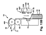
図12A−12Cを参照すると、係合デバイス402は、バッグを解放する。この解放は、シールが形成された後、またはシールが形成されている間、行われ得る。この解放は、シール裏当てバー68および加熱要素70が互いから離れるように移動する前(図12B参照)または後(図13B参照)に行われ得る。例示的実施形態では、コントローラは、グリッパ220、230、240、250を閉鎖位置(図11A−11C)から閉鎖位置(図12A−12C)に移動させることによって、係合デバイス402にバッグを解放させる。
Referring to FIGS. 12A-12C, the
依然として、図12A−12Cを参照すると、コントローラは、形成されたパッケージ12をウェブ16から分離するように送り出し機構52を制御する。第2の層22は、分離線32の残りの中央部分854(中央部分854は、図12A−12Cの例証においてすでに破断されている)に沿って破断され、パッケージ12を細長いウェブ16から分離する。図示される実施形態では、例示的実施形態において、コントローラは、バッグがシール配列56によって締め付けられている間に、矢印74によって示されるように、ウェブ16をバッグ18から引き離すように送り出し配列52を制御する。
Still referring to FIGS. 12A-12C, the controller controls the
図13A−13Cを参照すると、コントローラは、充填されたバッグ18が次の充填されていないバッグ18’から分離された後、形成されたパッケージ12を解放するようにシール配列56を制御する。図示される実施形態では、形成されたパッケージ12は、シール裏当てバー68を加熱要素70から離れるように移動させることによって解放される。
Referring to FIGS. 13A-13C, the controller controls the
再び、図3A−3Cを参照すると、コントローラ58は、次のバッグ18の開口部30を伴うウェブ16を装填位置に送り出し、サイクルは、再び開始する。コントローラは、ウェブから必要とされる数のパッケージを生産するために、要求に応じて、方法を繰り返し得る。
Referring again to FIGS. 3A-3C, the controller 58 delivers the
前述の実施形態は、本発明の側面の代表であり、例として提供され、本発明の側面の実装の包括的説明ではないことを理解されたい。 It should be understood that the foregoing embodiments are representative of aspects of the invention and are provided as examples and are not a comprehensive description of implementations of aspects of the invention.
本発明の種々の側面が、例示的実施形態において組み合わせて具現化されるように、本明細書に説明および図示され得るが、これらの種々の側面は、個々に、または種々の組み合わせおよびその部分的組み合わせのいずれかにおいて、多くの代替実施形態において実現され得る。本明細書に明示的に除外されない限り、全てのそのような組み合わせおよび部分的組み合わせは、本発明の範囲内であることが意図される。なおもさらに、代替材料、構造、構成、方法、デバイス、ソフトウェア、ハードウェア、制御論理等の本発明の種々の側面および特徴に関する種々の代替実施形態等が、本明細書に説明され得るが、そのような説明は、現在公知であるか、または後に開発されるかどうかにかかわらず、利用可能な代替実施形態の完全または包括的リストであるものと意図されない。当業者は、そのような実施形態が本明細書に明示的に開示されない場合でも、本発明の側面、概念、または特徴のうちの1つ以上のものを本発明の範囲内の追加の実施形態に容易に適合させ得る。加えて、本発明のいくつかの特徴、概念、または側面が、好ましい配列または方法として本明細書に説明され得る場合でも、そのような説明は、明示的にそのように述べられない限り、そのような特徴が要求されること、または必要であることを示唆することを意図するものではない。なおもさらに、例示的または代表的値および範囲が、本発明の理解を補助するために含まれ得るが、しかしながら、そのような値および範囲は、限定的意味において解釈されるべきではなく、そのように明示的に述べられる場合のみ、重要な値または範囲であるものと意図される。 Although various aspects of the invention may be described and illustrated herein as embodied in combination in an exemplary embodiment, these various aspects may be individually or in various combinations and portions thereof. Can be implemented in many alternative embodiments in any of the following combinations. All such combinations and subcombinations are intended to be within the scope of the invention, unless expressly excluded herein. Still further, various alternative embodiments relating to various aspects and features of the present invention, such as alternative materials, structures, configurations, methods, devices, software, hardware, control logic, etc. may be described herein. Such descriptions are not intended to be a complete or comprehensive list of alternative embodiments available, whether currently known or later developed. Those skilled in the art will recognize that one or more of the aspects, concepts, or features of the present invention are additional embodiments within the scope of the present invention, even if such embodiments are not explicitly disclosed herein. Can be easily adapted to. In addition, even though some features, concepts or aspects of the invention may be described herein as a preferred arrangement or method, such description is not intended unless explicitly stated so. It is not intended to suggest that such features are required or necessary. Still further, exemplary or representative values and ranges may be included to aid the understanding of the present invention; however, such values and ranges should not be construed in a limiting sense, as such Are intended to be significant values or ranges only when explicitly stated as such.
Claims (20)
接続されたバッグのウェブをバッグの開口部が係合デバイスより下にある位置まで前進させることと、
前記係合デバイスを開放することと、
前記バッグの前記開口部に部分的に開放された構成になるまで送風することと、
前記係合デバイスの一部が前記バッグの内側に配置され、前記係合デバイスの一部が前記バッグの外側に配置されるように、前記接続されたバッグのウェブを逆送りすることと、
前記係合デバイスが前記バッグに係合するように、前記係合デバイスを閉鎖することと、
前記係合デバイスを前記バッグの前記開口部が長方形形状有することをもたらす位置まで移動させることと
を含む、方法。 A method of making a package, the method comprising:
Advancing the connected bag web to a position where the bag opening is below the engagement device;
Opening the engagement device;
Blowing to a configuration partially open to the opening of the bag;
Back feeding the web of connected bags such that a portion of the engagement device is located inside the bag and a portion of the engagement device is located outside the bag;
Closing the engagement device such that the engagement device engages the bag;
Moving the engagement device to a position that results in the opening of the bag having a rectangular shape.
接続されたバッグのウェブをバッグの開口部が複数の対のグリッパより下にある位置まで前進させることと、
前記対のグリッパの各々を開放することと、
前記バッグの前記開口部に部分的に開放された構成になるまで送風することと、
前記対のグリッパの各々のうちの1つのグリッパが前記バッグの内側に配置されるように、前記接続されたバッグのウェブを逆送りすることと、
前記対のグリッパが前記バッグに係合するように、前記対のグリッパの各々を閉鎖することと、
前記対のグリッパのうちの少なくとも1つを前記バッグの前記開口部が長方形形状有することをもたらす位置まで移動させることと
を含む、方法。 A method of making a package, the method comprising:
Advancing the connected bag web to a position where the bag openings are below the plurality of pairs of grippers;
Opening each of the pair of grippers;
Blowing to a configuration partially open to the opening of the bag;
Back feeding the webs of the connected bags such that one gripper of each of the pair of grippers is located inside the bag;
Closing each of the pair of grippers such that the pair of grippers engages the bag;
Moving at least one of the pair of grippers to a position that results in the opening of the bag having a rectangular shape.
接続されたバッグのウェブを受け取るように構成されている送り出し機構と、
空気をバッグの開口部の中に吹きつけるように構成されている送風機と、
係合デバイスであって、前記係合デバイスは、
第1の対のグリッパと、
前記第1の対のグリッパから間隔を置かれている第2の対のグリッパと、
第3の対のグリッパと、
第4の対のグリッパであって、前記第3の対のグリッパおよび第4の対のグリッパは、互いに対して移動可能である、第4の対のグリッパと
を備え、前記第1の対のグリッパ、前記第2の対のグリッパ、前記第3の対のグリッパ、および前記第4の対のグリッパの各々は、開放位置と閉鎖位置との両方に移動可能である、係合デバイスと、
前記バッグの前記開口部をシールするように構成されているシール部材と
を備えている、装置。 An apparatus for producing a package, the apparatus comprising:
A delivery mechanism configured to receive a web of connected bags;
A blower configured to blow air into the opening of the bag;
An engagement device, the engagement device comprising:
A first pair of grippers;
A second pair of grippers spaced from the first pair of grippers;
A third pair of grippers;
A fourth pair of grippers, wherein the third pair of grippers and the fourth pair of grippers are movable with respect to each other, the fourth pair of grippers comprising: An engagement device, wherein each of the gripper, the second pair of grippers, the third pair of grippers, and the fourth pair of grippers are movable in both an open position and a closed position;
A sealing member configured to seal the opening of the bag.
Applications Claiming Priority (3)
| Application Number | Priority Date | Filing Date | Title |
|---|---|---|---|
| US201562156381P | 2015-05-04 | 2015-05-04 | |
| US62/156,381 | 2015-05-04 | ||
| PCT/US2016/020093 WO2016178733A1 (en) | 2015-05-04 | 2016-02-29 | Packaging machine |
Publications (2)
| Publication Number | Publication Date |
|---|---|
| JP2018514475A true JP2018514475A (en) | 2018-06-07 |
| JP2018514475A5 JP2018514475A5 (en) | 2019-04-11 |
Family
ID=57218179
Family Applications (1)
| Application Number | Title | Priority Date | Filing Date |
|---|---|---|---|
| JP2017557464A Withdrawn JP2018514475A (en) | 2015-05-04 | 2016-02-29 | Packaging machinery |
Country Status (11)
| Country | Link |
|---|---|
| US (4) | US10336489B2 (en) |
| EP (1) | EP3292047B1 (en) |
| JP (1) | JP2018514475A (en) |
| KR (1) | KR102591891B1 (en) |
| AU (1) | AU2016258449B2 (en) |
| BR (1) | BR112017023716B1 (en) |
| CA (1) | CA2985049A1 (en) |
| CL (1) | CL2017002770A1 (en) |
| CO (1) | CO2017011860A2 (en) |
| MX (1) | MX2017014098A (en) |
| WO (1) | WO2016178733A1 (en) |
Families Citing this family (7)
| Publication number | Priority date | Publication date | Assignee | Title |
|---|---|---|---|---|
| WO2016178733A1 (en) * | 2015-05-04 | 2016-11-10 | Automated Packaging Systems, Inc. | Packaging machine |
| BR112018007807A2 (en) | 2015-11-16 | 2018-10-30 | Automated Packaging Systems Inc | continuous sheet of preformed pouches, and method for forming packages |
| US11827419B2 (en) | 2019-01-31 | 2023-11-28 | Sealed Air Corporation (Us) | Reclosable bag and methods of forming and using the same |
| KR102133231B1 (en) * | 2020-02-24 | 2020-07-13 | (주)이엠로지스 | The apparatus of vinyl auto-packing for delivery |
| US20230399144A1 (en) | 2020-10-08 | 2023-12-14 | Sealed Air Corporation (Us) | Webs of cushioned closable bags |
| KR102313213B1 (en) | 2021-05-14 | 2021-10-15 | 디에이치 주식회사 | Packaging apparatus for packaging bags equipped with a label printer |
| NL2028767B1 (en) * | 2021-07-16 | 2023-01-23 | Dd Innovations B V | Device for packaging of medicine-units |
Family Cites Families (19)
| Publication number | Priority date | Publication date | Assignee | Title |
|---|---|---|---|---|
| US2272258A (en) * | 1938-11-04 | 1942-02-10 | Cons Packaging Machinery Corp | Bag opening and filling machine |
| US3254828A (en) | 1963-12-18 | 1966-06-07 | Automated Packaging Corp | Flexible container strips |
| AU4395479A (en) | 1978-02-10 | 1979-08-16 | Vodarich, U. | Bag making apparatus |
| US4201029A (en) | 1978-08-14 | 1980-05-06 | Automated Packaging Systems, Inc. | Method and apparatus for packaging |
| DE3118866C2 (en) * | 1981-05-13 | 1984-04-12 | Haver & Boecker, 4740 Oelde | "Machine for filling and closing plastic sacks, preferably gusseted sacks or flat sacks" |
| DE3203071A1 (en) * | 1982-01-30 | 1983-08-04 | Hoechst Ag, 6230 Frankfurt | METHOD AND DEVICE FOR AUTOMATICALLY INSERTING BOXED BAGS |
| JPS59163108A (en) * | 1983-03-05 | 1984-09-14 | 株式会社 フジパツクシステム | Regulating structure of width of grip of cylindrical bag in bagging packer |
| US4877068A (en) | 1988-07-15 | 1989-10-31 | Blake Gregory L | Bag loader and bag for beverage cans |
| US5077958A (en) * | 1989-08-18 | 1992-01-07 | Automated Packaging Systems, Inc. | Packaging machine and method |
| US5417639A (en) | 1993-10-07 | 1995-05-23 | Automated Packaging Systems, Inc. | Bags and method of making same |
| US5673541A (en) * | 1995-10-31 | 1997-10-07 | Emplex Systems, Inc. | Apparatus and method for forming, filling and sealing a bag |
| DE10140927A1 (en) * | 2001-08-15 | 2003-02-27 | Optima Filling & Packaging | Device for supplying a packaging machine with bags |
| US6742321B2 (en) * | 2002-09-30 | 2004-06-01 | Gates Automation, Inc. | Flange alignment and grasping assembly for bag handling apparatus |
| US7448185B2 (en) * | 2006-04-18 | 2008-11-11 | Automated Packaging Systems, Inc. | Method and apparatus for making packages with internal headers from preformed bags |
| WO2009036237A1 (en) * | 2007-09-12 | 2009-03-19 | Automated Packaging Systems, Inc. | Packaging machine |
| US9352867B2 (en) * | 2008-03-03 | 2016-05-31 | H.W.J. Designs For Agribusiness, Inc. | Bagging assembly |
| US9925694B2 (en) * | 2009-02-24 | 2018-03-27 | Gala Industries, Inc. | Continuous bagging processes and systems |
| US8539741B2 (en) | 2010-02-10 | 2013-09-24 | Triangle Package Machinery Company | Seal and cut method and apparatus |
| WO2016178733A1 (en) * | 2015-05-04 | 2016-11-10 | Automated Packaging Systems, Inc. | Packaging machine |
-
2016
- 2016-02-29 WO PCT/US2016/020093 patent/WO2016178733A1/en active Application Filing
- 2016-02-29 MX MX2017014098A patent/MX2017014098A/en unknown
- 2016-02-29 JP JP2017557464A patent/JP2018514475A/en not_active Withdrawn
- 2016-02-29 US US15/056,425 patent/US10336489B2/en active Active
- 2016-02-29 KR KR1020177033635A patent/KR102591891B1/en active IP Right Grant
- 2016-02-29 EP EP16789709.9A patent/EP3292047B1/en active Active
- 2016-02-29 BR BR112017023716-4A patent/BR112017023716B1/en active IP Right Grant
- 2016-02-29 AU AU2016258449A patent/AU2016258449B2/en active Active
- 2016-02-29 CA CA2985049A patent/CA2985049A1/en not_active Abandoned
-
2017
- 2017-11-02 CL CL2017002770A patent/CL2017002770A1/en unknown
- 2017-11-22 CO CONC2017/0011860A patent/CO2017011860A2/en unknown
-
2019
- 2019-07-01 US US16/458,690 patent/US11001401B2/en active Active
-
2020
- 2020-02-03 US US16/780,058 patent/US11040793B2/en active Active
-
2021
- 2021-06-03 US US17/337,999 patent/US20210284372A1/en active Pending
Also Published As
| Publication number | Publication date |
|---|---|
| EP3292047B1 (en) | 2019-12-25 |
| US11040793B2 (en) | 2021-06-22 |
| US11001401B2 (en) | 2021-05-11 |
| KR102591891B1 (en) | 2023-10-19 |
| BR112017023716A2 (en) | 2018-07-17 |
| AU2016258449A1 (en) | 2017-11-30 |
| US20200047933A1 (en) | 2020-02-13 |
| US20160325866A1 (en) | 2016-11-10 |
| KR20180002701A (en) | 2018-01-08 |
| BR112017023716B1 (en) | 2022-03-22 |
| AU2016258449B2 (en) | 2020-04-09 |
| CO2017011860A2 (en) | 2018-02-09 |
| US10336489B2 (en) | 2019-07-02 |
| WO2016178733A1 (en) | 2016-11-10 |
| EP3292047A4 (en) | 2018-10-17 |
| CL2017002770A1 (en) | 2018-07-06 |
| CA2985049A1 (en) | 2016-11-10 |
| EP3292047A1 (en) | 2018-03-14 |
| US20210284372A1 (en) | 2021-09-16 |
| US20200172277A1 (en) | 2020-06-04 |
| MX2017014098A (en) | 2018-03-16 |
Similar Documents
| Publication | Publication Date | Title |
|---|---|---|
| US11040793B2 (en) | Packaging machine | |
| US7654064B2 (en) | Packaging machine | |
| US20220258899A1 (en) | Seal flattener | |
| US11352158B2 (en) | Machine for forming packages from a web of preformed bags | |
| EP3634876B1 (en) | Web of preformed bags | |
| US20170369208A1 (en) | Bags and methods of making bags |
Legal Events
| Date | Code | Title | Description |
|---|---|---|---|
| A521 | Request for written amendment filed |
Free format text: JAPANESE INTERMEDIATE CODE: A523 Effective date: 20190228 |
|
| A621 | Written request for application examination |
Free format text: JAPANESE INTERMEDIATE CODE: A621 Effective date: 20190228 |
|
| A761 | Written withdrawal of application |
Free format text: JAPANESE INTERMEDIATE CODE: A761 Effective date: 20191107 |
|
| A977 | Report on retrieval |
Free format text: JAPANESE INTERMEDIATE CODE: A971007 Effective date: 20191121 |