BR112017023716B1 - Method and apparatus for manufacturing packaging - Google Patents
Method and apparatus for manufacturing packaging Download PDFInfo
- Publication number
- BR112017023716B1 BR112017023716B1 BR112017023716-4A BR112017023716A BR112017023716B1 BR 112017023716 B1 BR112017023716 B1 BR 112017023716B1 BR 112017023716 A BR112017023716 A BR 112017023716A BR 112017023716 B1 BR112017023716 B1 BR 112017023716B1
- Authority
- BR
- Brazil
- Prior art keywords
- pair
- fasteners
- bag
- opening
- jaws
- Prior art date
Links
Images


Classifications
-
- B—PERFORMING OPERATIONS; TRANSPORTING
- B65—CONVEYING; PACKING; STORING; HANDLING THIN OR FILAMENTARY MATERIAL
- B65B—MACHINES, APPARATUS OR DEVICES FOR, OR METHODS OF, PACKAGING ARTICLES OR MATERIALS; UNPACKING
- B65B43/00—Forming, feeding, opening or setting-up containers or receptacles in association with packaging
- B65B43/26—Opening or distending bags; Opening, erecting, or setting-up boxes, cartons, or carton blanks
- B65B43/267—Opening of bags interconnected in a web
-
- B—PERFORMING OPERATIONS; TRANSPORTING
- B65—CONVEYING; PACKING; STORING; HANDLING THIN OR FILAMENTARY MATERIAL
- B65B—MACHINES, APPARATUS OR DEVICES FOR, OR METHODS OF, PACKAGING ARTICLES OR MATERIALS; UNPACKING
- B65B5/00—Packaging individual articles in containers or receptacles, e.g. bags, sacks, boxes, cartons, cans, jars
- B65B5/04—Packaging single articles
- B65B5/045—Packaging single articles in bags
-
- B—PERFORMING OPERATIONS; TRANSPORTING
- B65—CONVEYING; PACKING; STORING; HANDLING THIN OR FILAMENTARY MATERIAL
- B65B—MACHINES, APPARATUS OR DEVICES FOR, OR METHODS OF, PACKAGING ARTICLES OR MATERIALS; UNPACKING
- B65B51/00—Devices for, or methods of, sealing or securing package folds or closures; Devices for gathering or twisting wrappers, or necks of bags
- B65B51/10—Applying or generating heat or pressure or combinations thereof
- B65B51/14—Applying or generating heat or pressure or combinations thereof by reciprocating or oscillating members
- B65B51/146—Closing bags
-
- B—PERFORMING OPERATIONS; TRANSPORTING
- B65—CONVEYING; PACKING; STORING; HANDLING THIN OR FILAMENTARY MATERIAL
- B65B—MACHINES, APPARATUS OR DEVICES FOR, OR METHODS OF, PACKAGING ARTICLES OR MATERIALS; UNPACKING
- B65B7/00—Closing containers or receptacles after filling
- B65B7/02—Closing containers or receptacles deformed by, or taking-up shape, of, contents, e.g. bags, sacks
Abstract
MÉTODO E APARELHO PARA FABRICAÇÃO DE EMBALAGENS. Um método exemplar para fabricação de embalagens inclui avançar uma rede de sacolas conectadas para uma posição onde uma abertura da sacola está abaixo de um dispositivo de engate e abrir o dispositivo de engate. Adicionalmente, o método exemplar inclui insuflar a abertura da sacola para uma configuração parcialmente aberta, e indexar de maneira reversa a rede de sacolas conectadas para que uma porção do dispositivo de engate seja disposta dentro da sacola e uma porção do dispositivo de engate seja disposta fora da sacola. Subsequentemente, o método exemplar inclui fechar o dispositivo de engate para que o dispositivo de engate se engate à sacola e mover o dispositivo de engate para uma posição que faz com que a abertura da sacola tenha um formato retangular.METHOD AND APPLIANCE FOR MANUFACTURING PACKAGING. An exemplary method of manufacturing packages includes advancing a network of connected bags to a position where an opening of the bag is below a latching device and opening the latching device. Additionally, the exemplary method includes inflating the opening of the bag to a partially open configuration, and reverse-indexing the network of connected bags so that a portion of the latching device is disposed inside the bag and a portion of the latching device is disposed outside. from the bag. Subsequently, the exemplary method includes closing the latching device so that the latching device engages the bag and moving the latching device to a position that causes the opening of the bag to be rectangular in shape.
Description
[001] A Patente U.S. n° 3.254.828, emitida em 7 de junho de 1966, para Hershey Lerner sob o título “Flexible Container Strips” se refere a chamadas sacolas em um rolo (aqui a patente AutoBag). A Patente U.S. n° 3.254.828 é aqui incorporada por referência na sua totalidade. Esta patente descreve uma rede sacolas conectadas por linhas de quebra, de preferência sob a forma de perfurações, sendo cada uma das sacolas aberta em uma face. Em uso, as sacolas são alimentadas sequencialmente para uma estação de carregamento. Quando na estação de carregamento, cada sacola é aberta, um produto é inserido e depois separado da rede e, se desejado, a sacola é então vedada para formar uma embalagem.[001] The U.S. Patent No. 3,254,828, issued June 7, 1966, to Hershey Lerner under the title “Flexible Container Strips” refers to so-called bags on a roll (here the AutoBag patent). The U.S. Patent No. 3,254,828 is incorporated herein by reference in its entirety. This patent describes a network of bags connected by break lines, preferably in the form of perforations, each bag being open on one side. In use, the bags are sequentially fed to a loading station. When at the loading station, each bag is opened, a product is inserted and then separated from the net and, if desired, the bag is then sealed to form a package.
[002] Estas faixas de recipientes na forma de cadeias de sacolas pré- abertas são fornecidas quer em um rolo como indicado na patente AutoBag ou colocadas em uma caixa de acordo com a maneira indicada na Pat. n° 4.201.029, concedida em 6 de maio de 1980, a Bernard Lerner et al. sob o título “Method and Apparatus for Packaging” (a seguir, a patente Wig-Wag). Essas faixas de recipientes foram vendidas pela Automated Packaging Systems, Inc. de Streetsboro, Ohio, o cessionário do presente caso, sob a marca registrada AutoBag e desfrutaram de um grande sucesso comercial.[002] These container bands in the form of pre-opened bag chains are supplied either on a roll as indicated in the AutoBag patent or placed in a box according to the manner indicated in Pat. No. 4,201,029, issued May 6, 1980, to Bernard Lerner et al. under the title “Method and Apparatus for Packaging” (hereinafter the Wig-Wag patent). These container ranges were sold by Automated Packaging Systems, Inc. of Streetsboro, Ohio, the assignee of this case, under the AutoBag trademark, and enjoyed great commercial success.
[003] Um método exemplificativo para fabricação de embalagens inclui avançar uma rede de sacolas conectadas para uma posição onde uma abertura da sacola está abaixo de um dispositivo de engate e abrir o dispositivo de engate. Adicionalmente, o método exemplificativo inclui insuflar a abertura da sacola para uma configuração parcialmente aberta, e indexar de maneira reversa a rede de sacolas conectadas para que uma porção do dispositivo de engate seja disposta dentro da sacola e uma porção do dispositivo de engate seja disposta fora da sacola. Subsequentemente, o método exemplificativo inclui fechar o dispositivo de engate para que o dispositivo de engate se engate à sacola e mover o dispositivo de engate para uma posição que faz com que a abertura da sacola tenha um formato retangular.[003] An exemplary method for manufacturing packages includes advancing a network of connected bags to a position where an opening of the bag is below a latching device and opening the latching device. Additionally, the exemplary method includes inflating the opening of the bag to a partially open configuration, and reverse-indexing the network of connected bags so that a portion of the latching device is disposed inside the bag and a portion of the latching device is disposed outside. from the bag. Subsequently, the exemplary method includes closing the latching device so that the latching device engages the bag and moving the latching device to a position that causes the opening of the bag to be rectangular in shape.
[004] Outro método exemplificativo de fazer embalagens inclui avançar uma rede de sacolas conectadas para uma posição em que uma abertura de uma sacola está abaixo de uma pluralidade de pares de prendedores e abrir cada par de prendedores. Adicionalmente, o método exemplificativo inclui insuflar a abertura da sacola para uma configuração parcialmente aberta e a indexação inversa da rede de sacolas conectadas, de modo que um prendedor de cada um dos pares de prendedores esteja disposto dentro da sacola. Subsequentemente, o método exemplificativo inclui o fechamento de cada um dos pares de prendedores de modo que os pares de prendedores engatem a sacola e movam pelo menos um dos pares de prendedores para uma posição que faz com que a abertura da sacola tenha um formato retangular.[004] Another exemplary method of making packages includes advancing a network of connected bags to a position where an opening of a bag is below a plurality of pairs of fasteners and opening each pair of fasteners. Additionally, the exemplary method includes inflating the bag opening to a partially open configuration and inversely indexing the network of connected bags so that one fastener from each of the pairs of fasteners is disposed within the bag. Subsequently, the exemplary method includes closing each of the fastener pairs so that the fastener pairs engage the bag and move at least one of the fastener pairs to a position that causes the bag opening to be rectangular in shape.
[005] Um aparelho exemplificativo para fazer embalagens inclui um mecanismo de indexação, um insuflador, um dispositivo de engate e um membro de vedação. O mecanismo de indexação é configurado para receber uma rede de sacolas conectadas. O insuflador é configurado para insuflar ar em uma abertura de uma sacola. O dispositivo de engate tem um primeiro par de prendedores, um segundo par de prendedores, um terceiro par de prendedores e um quarto par de prendedores. O segundo par de prendedores está afastado do primeiro par de prendedores e o terceiro par e o quarto par de prendedores são móveis um em relação ao outro. Cada um dos primeiro, segundo, terceiro e quarto par de prendedores são móveis para uma posição aberta e uma posição fechada. O membro de vedação é configurado para vedar a abertura da sacola.[005] An exemplary apparatus for making packages includes an indexing mechanism, an inflator, an engaging device and a sealing member. The indexing engine is configured to receive a network of connected bags. The blower is configured to blow air into an opening in a bag. The latching device has a first pair of fasteners, a second pair of fasteners, a third pair of fasteners and a fourth pair of fasteners. The second pair of fasteners is spaced apart from the first pair of fasteners and the third pair and fourth pair of fasteners are movable relative to each other. Each of the first, second, third and fourth pairs of fasteners are movable to an open position and a closed position. The sealing member is configured to seal the opening of the bag.
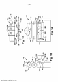
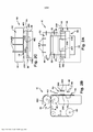
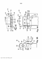
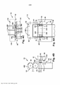
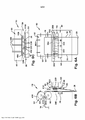
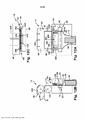
[006] A seguir a invenção será descrita com relação às figuras dos desenhos em anexo, onde: a FIG. 1 A é uma vista frontal de um aparelho exemplificativo para fazer embalagens a partir de uma rede alongada de sacolas interconectadas pré-formados; a FIG. IB é uma vista lateral do aparelho mostrado na Fig. 1A; a FIG. 1C é uma vista de cima do aparelho mostrado na Fig. 1A; a FIG. 2A é uma vista frontal do aparelho que mostra a rede alongada sendo avançada através do aparelho; a FIG. 2B é uma vista lateral do aparelho e da rede alongada mostrada na Fig. 2A; a FIG. 2C é uma vista de cima do aparelho e da rede alongada mostrada na Fig. 2A; a FIG. 3A é uma vista frontal do aparelho que mostra a abertura de rede alongada que está posicionada abaixo de um arranjo de abertura de sacola do aparelho; a FIG. 3B é uma vista lateral do aparelho e da rede alongada mostrada na Fig. 3A; a FIG. 3C é uma vista de cima do aparelho e da rede alongada mostrada na Fig. 3A; a FIG. 4A é uma vista frontal do aparelho que mostra dispositivos de engate da sacola movidos para a posição acima da abertura alongada da rede; a FIG. 4B é uma vista lateral do aparelho e da rede alongada mostrada na Fig. 4A; a FIG. 4C é uma vista de cima do aparelho e da rede alongada mostrada na Fig. 4A; a FIG. 5 A é uma vista frontal do aparelho que mostra a abertura da rede aberta por cima dos dispositivos de engate de sacola; a FIG. 5B é uma vista lateral do aparelho e da rede alongada mostrada na Fig. 5A; a FIG. 5C é uma vista de cima do aparelho e da rede alongada mostrada na Fig. 5A; a FIG. 6A é uma vista frontal do aparelho que mostra a rede sendo indexada de modo inverso para posicionar os dispositivos de engate da sacola dentro da abertura da rede; a FIG. 6B é uma vista lateral do aparelho e da rede alongada mostrada na Fig. 6A; FIG. 6C é uma vista de cima do aparelho e da rede alongada mostrada na Fig. 6A; a FIG. 7A é uma vista frontal do aparelho que mostra dispositivos de engate de sacola engatando uma sacola da rede na abertura; a FIG. 7B é uma vista lateral do aparelho e da rede alongada mostrada na Fig. 7A; a FIG. 7C é uma vista de cima do aparelho e da rede alongada mostrada na Fig. 7A; a FIG. 8A é uma vista frontal do aparelho que mostra os dispositivos de engate se movendo para prover uma abertura de sacola retangular; a FIG. 8B é uma vista lateral do aparelho e da rede alongada mostrada na Fig. 8A; a FIG. 8C é uma vista de cima do aparelho e da rede alongada mostrada na Fig. 8A; a FIG. 9A é uma vista frontal do aparelho que mostra um produto retangular posicionado acima da abertura retangular da sacola; a FIG. 9B é uma vista lateral do aparelho e da rede alongada mostrada na Fig. 9A; a FIG. 9C é uma vista de cima do aparelho e da rede alongada mostrada na Fig. 9A; a FIG. 10A é uma vista frontal do aparelho que mostra um produto retangular posicionado na sacola aberta; a FIG. 10B é uma vista lateral do aparelho e da rede alongada mostrada na Fig. 10A; a FIG. 10C é uma vista de cima do aparelho e da rede alongada mostrada na Fig. 10A; a FIG. 11 A é uma vista frontal do aparelho que mostra os dispositivos de engate da sacola se movendo para fechar a sacola e a sacola sendo vedada por um arranjo de vedação do aparelho; a FIG. 11B é uma vista lateral do aparelho e da rede alongada mostrada na Fig. 11A; a FIG. 11C é uma vista de cima do aparelho e da rede alongada mostrada na Fig. 11A; a FIG. 12A é uma vista frontal do aparelho que mostra a indexação reversa da rede para separar a sacola cheia e vedada da rede; a FIG. 12B é uma vista lateral do aparelho e da rede alongada mostrada na Fig. 12A; a FIG. 12C é uma vista de cima do aparelho e da rede alongada mostrada na Fig. 12A; a FIG. 13A é uma vista frontal do aparelho que mostra a liberação da sacola cheia e vedada do aparelho; a FIG. 13B é uma vista lateral do aparelho e da rede alongada mostrada na Fig. 13A; a FIG. 13C é uma vista de cima do aparelho e da rede alongada mostrada na Fig. 13A; a FIG. 14 é uma vista, parcialmente cortada, de uma rede alongada de sacolas; a FIG. 15 é uma vista em corte tomada ao longo do plano indicado pelas linhas 15-15 na FIG. 14; a FIG. 16 é uma vista frontal de uma modalidade exemplificativa de uma embalagem; a FIG. 17 é uma vista tomada ao longo do plano indicado pelas linhas 17-17 na FIG. 16; e a FIGS. 18A-18E ilustram uma modalidade exemplificativa de um conjunto de vedação.[006] Next, the invention will be described with reference to the figures of the attached drawings, where: FIG. 1A is a front view of an exemplary apparatus for making packages from an elongated network of interconnected preformed bags; FIG. IB is a side view of the apparatus shown in Fig. 1A; FIG. 1C is a top view of the apparatus shown in Fig. 1A; FIG. 2A is a front view of the apparatus showing the elongated net being advanced through the apparatus; FIG. 2B is a side view of the apparatus and elongated net shown in Fig. 2A; FIG. 2C is a top view of the apparatus and elongated net shown in Fig. 2A; FIG. 3A is a front view of the apparatus showing the elongated mesh opening that is positioned below a bag opening arrangement of the apparatus; FIG. 3B is a side view of the apparatus and elongated net shown in Fig. 3A; FIG. 3C is a top view of the apparatus and elongated net shown in Fig. 3A; FIG. 4A is a front view of the apparatus showing bag latching devices moved into position above the elongate opening of the net; FIG. 4B is a side view of the apparatus and elongated net shown in Fig. 4A; FIG. 4C is a top view of the apparatus and elongated net shown in Fig. 4A; FIG. 5A is a front view of the apparatus showing the opening of the net open above the bag hooking devices; FIG. 5B is a side view of the apparatus and elongated net shown in Fig. 5A; FIG. 5C is a top view of the apparatus and elongated net shown in Fig. 5A; FIG. 6A is a front view of the apparatus showing the net being reverse-indexed to position the bag latching devices within the opening of the net; FIG. 6B is a side view of the apparatus and elongated net shown in Fig. 6A; FIG. 6C is a top view of the apparatus and elongated net shown in Fig. 6A; FIG. 7A is a front view of the apparatus showing bag engaging devices engaging a net bag in the opening; FIG. 7B is a side view of the apparatus and elongated net shown in Fig. 7A; FIG. 7C is a top view of the apparatus and elongated net shown in Fig. 7A; FIG. 8A is a front view of the apparatus showing the latching devices moving to provide a rectangular bag opening; FIG. 8B is a side view of the apparatus and elongated net shown in Fig. 8A; FIG. 8C is a top view of the apparatus and elongated net shown in Fig. 8A; FIG. 9A is a front view of the apparatus showing a rectangular product positioned above the rectangular opening of the bag; FIG. 9B is a side view of the apparatus and elongated net shown in Fig. 9A; FIG. 9C is a top view of the apparatus and elongated net shown in Fig. 9A; FIG. 10A is a front view of the apparatus showing a rectangular product positioned in the open bag; FIG. 10B is a side view of the apparatus and elongated net shown in Fig. 10A; FIG. 10C is a top view of the apparatus and elongated net shown in Fig. 10A; FIG. 11A is a front view of the apparatus showing the bag engaging devices moving to close the bag and the bag being sealed by a sealing arrangement of the apparatus; FIG. 11B is a side view of the apparatus and elongated net shown in Fig. 11A; FIG. 11C is a top view of the apparatus and elongated net shown in Fig. 11A; FIG. 12A is a front view of the apparatus showing reverse indexing of the net to separate the filled and sealed bag from the net; FIG. 12B is a side view of the apparatus and elongated net shown in Fig. 12A; FIG. 12C is a top view of the apparatus and elongated net shown in Fig. 12A; FIG. 13A is a front view of the apparatus showing the release of the filled and sealed bag from the apparatus; FIG. 13B is a side view of the apparatus and elongated net shown in Fig. 13A; FIG. 13C is a top view of the apparatus and elongated net shown in Fig. 13A; FIG. 14 is a view, partially cut away, of an elongated network of bags; FIG. 15 is a sectional view taken along the plane indicated by lines 15-15 in FIG. 14; FIG. 16 is a front view of an exemplary embodiment of a package; FIG. 17 is a view taken along the plane indicated by lines 17-17 in FIG. 16; and FIGS. 18A-18E illustrate an exemplary embodiment of a seal assembly.
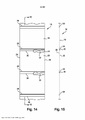
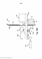
[007] A presente invenção refere-se a uma rede alongada 16 (FIGS. 14 e 15) de sacolas interconectadas pré-formadas 18. Em uma modalidade exemplificativa, a rede 16 tem uma abertura 30 definida em uma primeira dobra 20 e uma linha de separação 32 em uma segunda dobra 22. As redes 16 de sacolas interconectadas pré-formadas 18 podem ter uma grande variedade de formatos diferentes. Nas modalidades exemplificativas ilustradas pelas FIGS. 14 e 15, cada sacola pré-formada 18 é definida pelas primeira e segunda dobras 20, 22 da rede 16. As primeira e segunda bordas laterais 24, 26 da rede juntam hermeticamente as primeira e segunda dobras. As vedações pré-formadas 28 prolongam-se entre as primeira e segunda bordas laterais 24, 26. A abertura 30 se estende entre a primeira e o segunda bordas laterais 24, 26. A linha de separação 32, tal como uma linha de perfurações na segunda dobra 22, se estende entre as primeira e segunda bordas laterais 24, 26. Em uma modalidade exemplificativa, a abertura 30 é superposta sobre a linha de perfurações 32. Em outra modalidade exemplificativa, a abertura 30 e a linha de perfurações 32 são deslocadas.[007] The present invention relates to an elongated network 16 (FIGS. 14 and 15) of interconnected preformed
[008] A rede 16 de sacolas pré-formadas 18 ilustrada pelas FIGS. 14 e 15 é um exemplo da grande variedade de redes diferentes que podem ser usadas. Exemplos de redes aceitáveis de sacolas interconectadas pré-formadas incluem, mas não estão limitados às redes descritas na Pat. No. 3.254.828 de H. Lerner e US Pat. No. 5.957.824 de B. Lerner et al., que são aqui incorporadas por referência na sua totalidade.[008] The
[009] A rede 16 pode ser formada de qualquer material adequado. Exemplos de materiais adequados incluem, mas não estão limitados a materiais plásticos, polietileno, celofane, filmes de vinil, pliofilmes, película de acetato de celulose, poliestireno, polipropileno e qualquer material que pode ser vedado a quente.[009] The
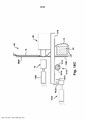
[0010] Fazendo referência às FIGS. 16 e 17, uma embalagem exemplificativa 12 inclui um compartimento vedado 36. A embalagem 12 pode ter qualquer número de compartimentos. O produto 40 está disposto no compartimento 36. O produto ilustrado 40 é uma caixa. No entanto, a embalagem 12 pode conter qualquer produto. O compartimento é definido pelas primeira e segunda bordas laterais 24, 26, a vedação pré-formada 28 e uma vedação 44 que é formada após o produto 40 ser carregado na sacola. No exemplo, a vedação 44 prolonga-se a partir da primeira borda lateral 24 para a segunda borda lateral 26 para vedar hermeticamente o compartimento 36. Em outra modalidade, a vedação divisória 28 pode não se prolongar todo o percurso da primeira borda lateral para a segunda borda lateral ou pode ser intermitente para permitir a comunicação entre o compartimento 44 e o ar externo ou o compartimento 44 e outro compartimento opcional da embalagem. As redes 18 de sacolas interligadas 16 podem ser feitas em uma ampla variedade de maneiras diferentes.[0010] Referring to FIGS. 16 and 17, an exemplary package 12 includes a sealed
[0011] As redes 18 de sacolas interligadas 16 podem ser usadas em uma grande variedade de aplicações diferentes. Por exemplo, as redes 18 de sacolas interligadas 16 podem ser usadas em uma grande variedade de diferentes máquinas de acondicionamento. As Figs. 1 A-1C ilustram uma modalidade exemplificativa de um aparelho 10 ou uma máquina de acondicionamento para fazer embalagens 12 a partir de uma rede alongada 16 de sacolas 18 interligados pré-formados, tal como as redes alongadas 16 das sacolas 18 ilustradas pelas Figs. 14 e 15.[0011]
[0012] As FIGS. 1 A-1C a 13 A-13C ilustram esquematicamente um exemplo de uma máquina que é operada para fazer embalagens 12 a partir de uma rede alongada 16 de sacolas interconectadas pré-formadas 18. Qualquer aparelho representado pelas ilustrações esquemáticas de 1 A-1C a 13A-13C pode ser utilizado que execute as funções mostradas pelas Figs. 1 A-1C a 13A-13C. Os conceitos do aparelho 10 podem ser implementados em qualquer uma de uma grande variedade de máquinas de acondicionamento. Por exemplo, a Patente dos EUA n° 3.254.828 de H. Lerner e Patente dos EUA n° 4.928.455 de Gereby et al., Patente dos EUA n° 5.341.625 de Kramer, Patente dos EUA n° 5.394.676 de B. Lerner et al., Patente dos EUA n° 6.543.201 para Cronauer et al., Patente dos EUA n° 6.742.317, Patente dos EUA n° 5.394.676, Patente dos EUA n° 5.371.521 e Patente dos EUA n° 4.899.520 descrevem máquinas de acondicionamento que podem ser modificadas de acordo com a presente invenção para fazer embalagens a partir de uma rede alongada de sacolas interligadas pré-formadas e são aqui todas incorporadas por referência na sua totalidade.[0012] FIGS. 1A-1C through 13A-13C schematically illustrate an example of a machine that is operated to make packages 12 from an
[0013] Com referência agora às FIGS. 1 A-1C, o aparelho ilustrado 10 inclui um fornecimento 50 (figura 2B) da rede alongada 16 de sacolas interconectadas pré-formadas 18, um mecanismo de indexação 52, um arranjo de abertura 54, um arranjo de vedação 56 e um controlador (não mostrado). O fornecimento 50 compreende a rede alongada 16 que é enrolada ou dobrada para encenar uma quantidade relativamente grande da rede em um espaço relativamente pequeno. A rede 16 é encaminhada do fornecimento 50 ao longo de um trajeto de deslocamento P para o mecanismo de indexação 52. O mecanismo de indexação 52 recebe a rede 16 do fornecimento e move a rede ao longo do trajeto de deslocamento P. O mecanismo de indexação 52 pode assumir uma grande variedade de formas diferentes. Por exemplo, qualquer mecanismo de indexação que pode ser controlado para indexar sacolas da rede para posições selecionadas ao longo do trajeto de deslocamento pode ser usado. No exemplo ilustrado, o mecanismo de indexação compreende um par de rolos 60 que formam um estreitamento que engata a rede 16. Os rolos 60 são acionados de forma seletiva por um motor (não mostrado) para indexar sacolas da rede para posições selecionadas ao longo do trajeto de deslocamento P.[0013] Referring now to FIGS. 1A-1C, the illustrated
[0014] Referindo-se às FIGS. 1 A-1C, o arranjo de abertura 54 é posicionado ao longo do trajeto de deslocamento P para abrir cada sacola que deve ser carregada e vedada. Na modalidade ilustrada, o arranjo de abertura 54 compreende um insuflador opcional 400 e um dispositivo de engate 402. No entanto, o arranjo de abertura 54 pode assumir uma grande variedade de formas diferentes. O insuflador opcional 400 pode ter uma grande variedade de formas diferentes. Na modalidade ilustrada, o insuflador 400 compreende uma pluralidade de bocais 210 posicionados acima dos rolos 60 do mecanismo de indexação 52. Os bocais ilustrados 210 são orientados para baixo para insuflar o ar para baixo, para além dos rolos 60, ao longo do trajeto de deslocamento P da rede 18.[0014] Referring to FIGS. 1A-1C, opening
[0015] O dispositivo de engate 402 pode ter uma grande variedade de formas diferentes. Na modalidade ilustrada, o dispositivo de engate 402 compreende um primeiro par de prendedores 220 e um segundo par de prendedores 230. O primeiro par de prendedores 220 está afastado do segundo par de prendedores 230 e ambos estão configurados para prender a primeira dobra 20 da sacola 16. Em uma modalidade exemplificativa, o espaçamento S (Fig. 1 A) entre os prendedores 220, 230 é ajustável. Este espaçamento opcional pode ser automático e controlado pelo controlador ou o espaçamento pode ser ajustado manualmente. Isso permite que o dispositivo de engate forneça aberturas 800 (veja a Fig. 8) com diferentes larguras.[0015] The
[0016] O dispositivo de engate 402 também inclui um terceiro par de prendedores 240 e um quarto par de prendedores 250. O terceiro par de prendedores 240 e o quarto par de prendedores 250 são móveis um em relação ao outro e estão configurados para prender as bordas laterais 24, 26 da sacola 18. O terceiro e quarto pares de prendedores 240, 250 são omitidos nas FIGs. 11B, 12B e 13B para ilustrar mais claramente a abertura do primeiro e segundo pares de prendedores 220, 230.[0016] The
[0017] Os prendedores 220 e 230 prendem a abertura 30 e se movem para criar a abertura retangular 800 como será descrito em mais detalhes abaixo. Essa abertura retangular permite que itens grandes, como itens retangulares, como caixas sejam acondicionados dentro da sacola 18.[0017]
[0018] Referindo-se às FIGS. 1 A-1C, o controlador está em comunicação com o arranjo de indexação 52, o arranjo de abertura 54 e o arranjo de vedação 56. O controlador controla o arranjo de indexação 52, o arranjo de abertura 54 e o arranjo de vedação 56 para converter as sacolas pré- formadas 18 em embalagens 12. Uma grande variedade de controladores pode ser usada e programada para controlar o arranjo de indexação 52, o arranjo de abertura 54 e o arranjo de vedação 56 como aqui descrito. Por exemplo, os algoritmos do controlador e do controlador descritos na Pat. dos EUA n° 5.341.625 de Kramer podem ser modificados para controlar o arranjo de indexação 52, o arranjo de abertura 54 e o arranjo de vedação 56 para formar as embalagens.[0018] Referring to FIGS. 1A-1C, the controller is in communication with the
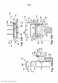
[0019] Referindo-se às FIGS. 2A-2C e 3A-3C, o controlador controla o mecanismo de indexação 52 para indexar a rede 16 para a frente ao longo do trajeto de deslocamento, conforme indicado pelas setas P, até a abertura 30 da sacola 18 estar logo abaixo do dispositivo de engate 402 na modalidade exemplificativa. Em modalidades alternativas, a abertura 30 é indexada para outras posições. Por exemplo, a abertura 30 pode ser indexada para qualquer posição em que o insuflador 400 possa insuflar a abertura 30 aberta ou pelo menos parcialmente aberta. Por exemplo, a abertura 30 pode inicialmente ser posicionada acima do dispositivo de engate 402, ser aberta pelo insuflador 400 e então ser movida para a posição ilustrada pelas Figs. 3A-3C.[0019] Referring to FIGS. 2A-2C and 3A-3C, the controller controls
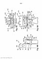
[0020] Em uma modalidade exemplificativa, o controlador controla o dispositivo de engate para mover os prendedores 220, 230, 240, 250 a partir de uma posição fechada (Ver Fig. 3A-3C) para uma posição aberta (ver Fig. 4A-4C) uma vez que a abertura 30 está posicionada abaixo do dispositivo de engate 402. Referindo-se às Figs. 5 A-5C, o controlador controla o insuflador 400 para insuflar o ar entre as dobras 20, 22 na abertura 30 da sacola. O ar é forçado entre as dobras através da abertura 30 para inflar a sacola 18. Em uma modalidade exemplificativa, a primeira dobra 20 da sacola inflada 18 está geralmente alinhada com ou alinhada com um interstício 500 (ver Fig. 5B) entre os membros de preensão de cada par de prendedores abertos 220, 230. Em uma modalidade exemplificativa, as bordas da sacola inflada 18 estão geralmente alinhadas com ou alinhadas com um interstício 520 (ver Figuras 5A e 5C) entre os membros de preensão de cada par aberto de prendedores 240, 250.[0020] In an exemplary embodiment, the controller controls the latching device to move
[0021] Referindo-se às Figs. 6A-6C, em uma modalidade exemplificativa, o controlador 58 faz com que o mecanismo de indexação 52 inverta o índice da rede como indicado pela seta 612 enquanto os pares de prendedores 220, 230 estão abertos. O insuflador 400 pode opcionalmente ser parado durante a indexação inversa. A indexação inversa puxa a primeira dobra 20 da sacola 18 para o interstício 500 entre os membros de preensão de cada par de prendedores abertos 220, 230. A indexação inversa também puxa as bordas 24, 26 da sacola 18 para dentro do interstício 520 entre os elementos de preensão de cada par de prendedores abertos 240, 250.[0021] Referring to Figs. 6A-6C, in an exemplary embodiment, controller 58
[0022] Referindo-se às FIGS. 7A-7C, em uma modalidade exemplificativa, o controlador 58 faz com que os pares de prendedores 220, 230, 240, 250 se movam da posição aberta para a posição fechada. A primeira dobra 20 da sacola 18 é presa entre os elementos de preensão de cada um dos pares de prendedores 220, 230. As bordas 24, 26 da sacola 18 são presas entre os membros de preensão de cada par de prendedores 240, 250.[0022] Referring to FIGS. 7A-7C, in an exemplary embodiment, controller 58 causes pairs of
[0023] Referindo-se às FIGS. 8A-8C, cada sacola 18 é provida com uma abertura retangular 800 em uma posição em que a sacola é carregada com um produto 40. Referindo-se às Figs. 8A-8C, em uma modalidade exemplificativa, o controlador controla o dispositivo de engate 402 para prover a sacola 18 com a abertura retangular 800 para carregamento. Na modalidade ilustrada, os pares de membros de preensão 220, 230 deslocam a primeira dobra 20 para fora da segunda dobra 22 como indicado pelas setas 850 (ver as Figuras 8B e 8C). Ao mesmo tempo, os pares de membros de preensão 240, 250 movem as bordas 24, 26 umas sobre as outras, conforme indicado pelas setas 860 (ver as Figuras 8A e 8C). O movimento dos pares de membros de preensão 240, 250 rasga a linha de perfurações 32 na segunda camada 22. Como tal, as porções de borda 852 da sacola 18 são rasgadas das porções de borda 852' da sacola seguinte 18', permitindo que a abertura retangular 800 seja formada. Em uma modalidade exemplificativa, a segunda dobra 22 desliza entre os pares de membros de preensão 240, 250 à medida que os pares de membros de preensão 240, 250 se deslocam da posição ilustrada pelas FIGS. 7A-7C para a posição ilustrada pelas FIGS. 8A-8C. Uma porção central 854 da linha de perfurações 32 na segunda camada 22 da sacola 18 permanece intacta. Isto deixa a sacola 18 conectada à sacola 18 ', enquanto a sacola 18 tem a abertura retangular 800. A abertura retangular 800 é de pelo menos 6 polegadas por 6 polegadas. Em certas modalidades, a abertura retangular 800 pode ser de 6 polegadas por 6 polegadas, 9 polegadas por 9 polegadas, 12 polegadas por 12 polegadas, 18 polegadas por 18 polegadas, ou qualquer combinação delas.[0023] Referring to FIGS. 8A-8C, each
[0024] Os pares de membros de preensão 220, 230 podem mover a primeira dobra 20 para fora da segunda dobra 22 em uma grande variedade de formas diferentes. Na modalidade ilustrada, os pares de membros de preensão 220, 230 estão conectados a uma barra 68 que faz parte do conjunto de vedação 56. Nesta modalidade, a barra 68 move os pares de membros de preensão 220, 230 afixados. No entanto, os pares de membros de preensão 220, 230 podem ser movidos por um atuador que é separado da barra 68. Os pares de membros de preensão 240, 250 podem mover as bordas 24, 26 umas sobre as outras de várias maneiras diferentes. Na modalidade ilustrada, os pares de membros de preensão 240, 250 se deslocam em uma fenda 870 em um elemento do aparelho 10. Os pares de membros de preensão 240, 250 podem ser acionados por um motor, um atuador linear ou qualquer outro mecanismo.[0024] Pairs of gripping
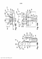
[0025] Referindo-se às Figs. 9A-9C e 10A-10C, a sacola 18 é mantida com a abertura retangular 800 na posição de carga e o produto 40 é carregado na sacola 18. O produto pode ser carregado manualmente ou automaticamente. Na modalidade ilustrada, a posição em que a sacola 18 é carregada é também a posição em que a sacola 18 é vedada após a abertura retangular 800 ser fechada. Em uma outra modalidade, a posição em que a sacola é carregada é diferente da posição em que a sacola é vedada. Nesta modalidade, o controlador faz com que o mecanismo de indexação 52 mova a sacola 18 para a posição de vedação depois que a sacola é carregada com o produto 40 e fechada.[0025] Referring to Figs. 9A-9C and 10A-10C, the
[0026] Em uma modalidade exemplificativa, uma vez que o produto é carregado na sacola 18, um operador pode fornecer um sinal para o controlador que indica que o carregamento está completo ou a conclusão do carregamento pode ser detectada automaticamente. O aparelho 10 pode ser configurado para permitir que o operador forneça o sinal de carregamento completo ao controlador de uma grande variedade de maneiras diferentes. Por exemplo, o aparelho pode ter um pedal de controle (não mostrado) ou o arranjo de vedação 56 pode ter uma porção que o operador pode empurrar para indicar que o carregamento está completo e é hora de vedar a embalagem. Da mesma forma, o aparelho pode ser configurado para detectar automaticamente o carregamento concluído e fornecer ao controlador um sinal que indica esse fato. Por exemplo, o aparelho pode incluir um contador ou pode pesar a embalagem para detectar o carregamento concluído.[0026] In an exemplary embodiment, once the product is loaded into the
[0027] Referindo-se às Figs. 11A-11C, o sinal do operador ou a detecção do carregamento concluído é comunicado ao controlador e faz com que o dispositivo de engate 402 feche a sacola. Na modalidade ilustrada, os pares de membros de preensão 220, 230 movem a primeira dobra 20 de volta na direção segunda dobra 22 como indicado pelas setas 1150 (ver as Figuras 11B e 11C). Ao mesmo tempo, os pares de membros de preensão 240, 250 movem as bordas 24, 26 afastados uma da outra como indicado pelas setas 1160 para fechar a abertura da sacola 30 (ver figura 11C). Em uma modalidade exemplificativa, a segunda dobra 22 desliza entre cada um dos pares de membros de preensão 240, 250 à medida que os pares de membros de preensão 240, 250 se movem da posição ilustrada pelas FIGS. 10A-10C para a posição ilustrada pelas FIGS. 11A-11C. Na modalidade ilustrada, uma porção central 854 da linha de perfurações 32 na segunda camada 22 da sacola 18 permanece intacta. Como tal, a sacola fechada 18 permanece conectada à sacola 18'.[0027] Referring to Figs. 11A-11C, the operator signal or detection of loading completed is communicated to the controller and causes latching
[0028] Ainda se referindo às FIGS. 11A-11C, a sacola pode ser vedada na posição ilustrada pelas Figs. 11A-11C ou o dispositivo de engate 402 pode liberar a sacola e a sacola pode ser indexada para outra posição para vedação. Em uma modalidade exemplificativa, a sacola é vedada enquanto o dispositivo de engate 402 segura a sacola 18 fechada. O arranjo de vedação 56 é posicionado ao longo do trajeto de deslocamento P para prover a vedação 44. O arranjo de vedação 56 pode assumir uma grande variedade de formas diferentes. Por exemplo, qualquer mecanismo que aplique calor na rede para vedar as primeira e segunda redes juntas para formar a vedação 44 pode ser implementado.[0028] Still referring to FIGS. 11A-11C, the bag can be sealed in the position illustrated by Figs. 11A-11C or latching
[0029] Na modalidade ilustrada, o arranjo de vedação compreende uma barra de suporte de vedação 68 e um elemento de aquecimento 70 que é movido de forma seletiva para dentro e para fora do engate. Com referência à Fig. 1 IB, quando a rede está na posição de vedação, o controlador controla o arranjo de vedação 56 para apertar a rede 16 entre a barra de suporte de vedação 68 e o elemento de aquecimento 70. Em uma modalidade exemplificativa, a barra de suporte de vedação 68 compreende um elemento de suporte de vedação de borracha 1168. A barra de suporte de vedação 68 pode ser movida para a posição de aperto (ver Fig. 1 IB) a partir da posição não amolecida (veja a Fig. 10B) sob uma força baixa, tal como uma força que é menor do que uma força que pode ferir um dedo que pode estar entre o elemento de suporte de vedação de borracha 1168 e o elemento de aquecimento 70. Além disso, o elemento de suporte de vedação de borracha 1168 não é aquecido.[0029] In the illustrated embodiment, the sealing arrangement comprises a sealing
[0030] Em uma modalidade exemplificativa, o elemento de aquecimento 70 é movido para a posição de aperto (veja a Fig. 11B) a partir da posição não amolecida (veja a Fig. 10B) e/ou o calor é aplicado pelo elemento de aquecimento 70 apenas após o elemento de suporte de vedação de borracha 1168 ter sido movido para a posição apertada. O calor é aplicado à rede para vedar as dobras da rede entre a primeira borda lateral 24 e a segunda borda lateral 26. O elemento de aquecimento 70 pode estar continuamente ligado (isto é, sempre quente quando a máquina é ligada) ou o elemento de aquecimento 70 pode ser controlado para aplicar apenas calor quando a sacola 18 é apertado e/ou um sinal de vedação é fornecido pelo controlador. As primeira e segunda dobras 20, 22 são vedadas juntas para formar o compartimento 36.[0030] In an exemplary embodiment, the
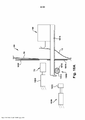
[0031] As Figs. 18A-18E ilustram uma modalidade exemplificativa de um conjunto de vedação 56 que compreende uma barra de suporte de vedação 68 e um elemento de aquecimento 70 que são movidos de forma seletiva para dentro e para fora do engate. Na modalidade exemplificativa, o elemento de aquecimento 70 é movido por um atuador 1800, tal como um atuador pneumático ou um atuador de solenoide. A barra de suporte de vedação ilustrada 68 é movida por um atuador de força baixa 1810 e é mantida no lugar por um atuador de aperto 1820.[0031] Figs. 18A-18E illustrate an exemplary embodiment of a
[0032] O atuador de força baixa 1810 pode ter uma grande variedade de formas diferentes. Em uma modalidade exemplificativa, o atuador de força baixa 1810 compreende um servomotor 1812. Na modalidade ilustrada, o servomotor 1812 aciona uma engrenagem de pinhão 1814 que aciona uma prateleira de engrenagem 1816. No entanto, qualquer arranjo de acionamento pode ser empregado. Em uma modalidade exemplificativa, o atuador de força baixa aplica uma força baixa, como uma força que é menor do que uma força que pode ferir o dedo de uma pessoa que pode estar entre a barra de suporte de vedação 68 e um painel frontal 1850 da máquina.[0032] The 1810 Low Force Actuator can have a wide variety of different shapes. In an exemplary embodiment, the
[0033] O atuador de aperto 1820 pode ter uma grande variedade de formas diferentes. Em uma modalidade exemplificativa, o atuador de aperto 1820 é um atuador pneumático ou um atuador de solenoide. Qualquer tipo de atuador pode ser usado. Na modalidade ilustrada, o atuador de aperto 1820 inclui um elemento de trinca 1822 para acoplar seletivamente o atuador de aperto 1820 ao atuador de força baixa 1810 e desacoplar o atuador de aperto 1820 do atuador de força baixa 1810.[0033] The 1820 clamping actuator can have a wide variety of different shapes. In an exemplary embodiment, the squeezing
[0034] A Fig. 18A ilustra o conjunto de vedação 56 em uma posição aberta ou de carga, na posição aberta ou de carga, o atuador de força baixa 1810 posiciona a barra de suporte de vedação 68 em uma relação espaçada ao painel frontal 1850 da máquina 10. Nesta posição, o atuador 1800 posiciona o elemento de aquecimento 70 em uma relação rebaixada em relação ao painel frontal 1850. Isso evita que um usuário toque inadvertidamente o elemento de aquecimento. A seta 1860 na figura 18B ilustra o atuador de força baixa 1810 que move a barra de suporte de vedação 68 para uma posição engatada ou de vedação. A seta 1870 na Fig. 18C ilustra o elemento de trinca 1822 do atuador de aperto 1820 que se desloca para uma posição de acoplamento. A seta 1880 na Fig. 18D ilustra o acoplamento do atuador de aperto 1820 ao atuador de força baixa 1810, para segurar o atuador de força baixa 1810 na posição de aperto.[0034] Fig. 18A illustrates
[0035] A seta 1890 na figura 18E ilustra o elemento de aquecimento 70 movido pelo atuador 1800 para uma posição de aperto ou de vedação. Em uma modalidade exemplificativa, o elemento de aquecimento 70 é movido para a posição de aperto e/ou calor é aplicado pelo elemento de aquecimento 70 apenas após o elemento de suporte de vedação de borracha opcional 1168 ter sido movido para a posição de aperto. O atuador de aperto acoplado 1820 e o atuador de força baixa 1810 impedem o atuador e o elemento de aquecimento 70 de empurrar a barra de suporte de vedação 68 para longe. Ou seja, o atuador de aperto acoplado 1820 e o atuador de força baixa 1810 podem opor-se a uma força muito maior aplicada pelo atuador 1800 do que o atuador de força baixa 1810 sozinho. Uma vez que o atuador de aperto 1820 não está acoplado ao atuador de força baixa 1810 até a barra de suporte de vedação estar na posição ou substancialmente na posição, não há risco de que os dedos de um usuário possam ser comprimidos pelas forças aplicadas pelo atuador 1800 e pelo atuador de aperto 1820. A única força que poderia ser aplicada aos dedos de um usuário é a força aplicada pelo atuador de força baixa 1810, que é menor do que uma força que possivelmente poderia ferir um dedo. Na modalidade ilustrada, a barra de suporte de vedação 68 compreende o elemento de suporte de vedação de borracha 1168, que não é aquecido. O calor é aplicado na rede para vedar as dobras da rede em conjunto. Em uma modalidade exemplificativa, a rede 16 é indexada inversamente enquanto a sacola 18 é apertada entre a barra de suporte de vedação 68 e o elemento de aquecimento 70 para separar a sacola 18 do resto da rede. As operações ilustradas pelas Figs. 18A-18E são executadas na ordem inversa para liberar a sacola.[0035] Arrow 1890 in Figure 18E illustrates
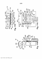
[0036] Referindo-se às Figs. 12A-12C, o dispositivo de engate 402 libera a sacola. Esta liberação pode ser após a formação da vedação ou enquanto a vedação está sendo formada. Esta liberação pode ser antes (ver Fig. 12B) ou depois (ver Fig. 13B) da barra de suporte de vedação 68 e um elemento de aquecimento 70 se afastarem um do outro. Em uma modalidade exemplificativa, o controlador faz com que o dispositivo de engate 402 libere a sacola fazendo com que os prendedores 220, 230, 240, 250 se movam da posição fechada (Figuras 11A-11C) para a posição fechada (Figuras 12A- 12C).[0036] Referring to Figs. 12A-12C, latching
[0037] Ainda se referindo às Figs. 12A-12C, o controlador controla o mecanismo de indexação 52 para separar a embalagem formada 12 da rede 16. A segunda dobra 22 é quebrada ao longo da porção do meio restante 854 (a porção do meio 854 já está quebrada na ilustração das Figs. 12A-12C) da linha de separação 32 para separar a embalagem 12 da rede alongada 16. Na modalidade ilustrada, o controlador controla o arranjo de indexação 52 para puxar a rede 16 para fora da sacola 18 como indicado pelas setas 74 enquanto a sacola é apertada pelo arranjo de vedação 56 em uma modalidade exemplificativa.[0037] Still referring to Figs. 12A-12C, the controller controls the
[0038] Referindo-se às Figs. 13A-13C, o controlador controla o arranjo de vedação 56 para liberar a embalagem formada 12 depois de a sacola cheia 18 ser separada da próxima sacola 18' não enchida. Na modalidade ilustrada, a embalagem formada 12 é liberada movendo a barra de suporte de vedação 68 para longe do elemento de aquecimento 70.[0038] Referring to Figs. 13A-13C, the controller controls the sealing
[0039] Referindo novamente às FIGS. 3A-3C, o controlador 58 indexa a rede 16 com a abertura 30 da sacola seguinte 18 para a posição de carga e o ciclo começa novamente. O controlador pode repetir o método conforme necessário para produzir tantas embalagens são necessários da rede.[0039] Referring again to FIGS. 3A-3C, the controller 58 indexes the net 16 with the
[0040] Deve ser entendido que as modalidades discutidas acima são representativas dos aspectos da invenção e são fornecidas como exemplos e não uma descrição exaustiva das implementações de um aspecto da invenção.[0040] It should be understood that the embodiments discussed above are representative of aspects of the invention and are provided as examples and not an exhaustive description of implementations of an aspect of the invention.
[0041] Embora vários aspectos da invenção sejam descritos e ilustrados aqui como incorporados em combinação nas modalidades exemplificativas, esses vários aspectos podem ser realizados em muitas modalidades alternativas, individualmente ou em várias combinações e subconjuntos das mesmas. A menos que expressamente aqui excluídos, todas essas combinações e subcombinações devem estar dentro do escopo da presente invenção. Além disso, embora possam ser aqui descritas várias modalidades alternativas quanto aos vários aspectos e características da invenção, tais como materiais, estruturas, configurações, métodos, dispositivos, software, hardware, lógica de controle e outros, tais descrições não se destinam a ser uma lista completa ou exaustiva de modalidades alternativas disponíveis, já conhecidas ou desenvolvidas posteriormente. Os versados na técnica podem adotar facilmente um ou mais dos aspectos, conceitos ou características da invenção em modalidades adicionais dentro do escopo da presente invenção, mesmo que tais modalidades não sejam expressamente aqui descritas. Além disso, apesar de algumas características, conceitos ou aspectos da invenção possam ser aqui descritos como sendo um arranjo ou método preferido, tal descrição não pretende sugerir que tal recurso é requerido ou necessário, a menos que expressamente indicado. Ainda adicionalmente, podem incluir-se valores e faixas exemplificativas ou representativas para auxiliar na compreensão da presente invenção, no entanto, tais valores e faixas não devem ser interpretadas em um sentido limitativo e devem ser valores ou faixas críticas apenas se assim for expressamente indicado.[0041] While various aspects of the invention are described and illustrated herein as incorporated in combination in the exemplary embodiments, those various aspects may be embodied in many alternative embodiments, individually or in various combinations and subsets thereof. Unless expressly excluded herein, all such combinations and subcombinations shall be within the scope of the present invention. Furthermore, while various alternative embodiments may be described herein as to the various aspects and features of the invention, such as materials, structures, configurations, methods, devices, software, hardware, control logic, and the like, such descriptions are not intended to be a complete or exhaustive list of available alternative modalities, already known or developed later. Those skilled in the art can readily adopt one or more of the aspects, concepts or features of the invention in additional embodiments within the scope of the present invention, even if such embodiments are not expressly described herein. Furthermore, while some features, concepts or aspects of the invention may be described herein as being a preferred arrangement or method, such description is not intended to suggest that such a feature is required or necessary, unless expressly indicated. Still further, exemplary or representative values and ranges may be included to aid in understanding the present invention, however, such values and ranges should not be interpreted in a limiting sense and should be critical values or ranges only if expressly stated.
Claims (9)
Applications Claiming Priority (4)
| Application Number | Priority Date | Filing Date | Title |
|---|---|---|---|
| US201562156381P | 2015-05-04 | 2015-05-04 | |
| US62/156,381 | 2015-05-04 | ||
| US62/156381 | 2015-05-04 | ||
| PCT/US2016/020093 WO2016178733A1 (en) | 2015-05-04 | 2016-02-29 | Packaging machine |
Publications (2)
| Publication Number | Publication Date |
|---|---|
| BR112017023716A2 BR112017023716A2 (en) | 2018-07-17 |
| BR112017023716B1 true BR112017023716B1 (en) | 2022-03-22 |
Family
ID=57218179
Family Applications (1)
| Application Number | Title | Priority Date | Filing Date |
|---|---|---|---|
| BR112017023716-4A BR112017023716B1 (en) | 2015-05-04 | 2016-02-29 | Method and apparatus for manufacturing packaging |
Country Status (11)
| Country | Link |
|---|---|
| US (4) | US10336489B2 (en) |
| EP (1) | EP3292047B1 (en) |
| JP (1) | JP2018514475A (en) |
| KR (1) | KR102591891B1 (en) |
| AU (1) | AU2016258449B2 (en) |
| BR (1) | BR112017023716B1 (en) |
| CA (1) | CA2985049A1 (en) |
| CL (1) | CL2017002770A1 (en) |
| CO (1) | CO2017011860A2 (en) |
| MX (1) | MX2017014098A (en) |
| WO (1) | WO2016178733A1 (en) |
Families Citing this family (7)
| Publication number | Priority date | Publication date | Assignee | Title |
|---|---|---|---|---|
| WO2016178733A1 (en) * | 2015-05-04 | 2016-11-10 | Automated Packaging Systems, Inc. | Packaging machine |
| BR112018007807A2 (en) | 2015-11-16 | 2018-10-30 | Automated Packaging Systems Inc | continuous sheet of preformed pouches, and method for forming packages |
| US11827419B2 (en) | 2019-01-31 | 2023-11-28 | Sealed Air Corporation (Us) | Reclosable bag and methods of forming and using the same |
| KR102133231B1 (en) * | 2020-02-24 | 2020-07-13 | (주)이엠로지스 | The apparatus of vinyl auto-packing for delivery |
| US20230399144A1 (en) | 2020-10-08 | 2023-12-14 | Sealed Air Corporation (Us) | Webs of cushioned closable bags |
| KR102313213B1 (en) | 2021-05-14 | 2021-10-15 | 디에이치 주식회사 | Packaging apparatus for packaging bags equipped with a label printer |
| NL2028767B1 (en) * | 2021-07-16 | 2023-01-23 | Dd Innovations B V | Device for packaging of medicine-units |
Family Cites Families (19)
| Publication number | Priority date | Publication date | Assignee | Title |
|---|---|---|---|---|
| US2272258A (en) * | 1938-11-04 | 1942-02-10 | Cons Packaging Machinery Corp | Bag opening and filling machine |
| US3254828A (en) | 1963-12-18 | 1966-06-07 | Automated Packaging Corp | Flexible container strips |
| AU4395479A (en) | 1978-02-10 | 1979-08-16 | Vodarich, U. | Bag making apparatus |
| US4201029A (en) | 1978-08-14 | 1980-05-06 | Automated Packaging Systems, Inc. | Method and apparatus for packaging |
| DE3118866C2 (en) * | 1981-05-13 | 1984-04-12 | Haver & Boecker, 4740 Oelde | "Machine for filling and closing plastic sacks, preferably gusseted sacks or flat sacks" |
| DE3203071A1 (en) * | 1982-01-30 | 1983-08-04 | Hoechst Ag, 6230 Frankfurt | METHOD AND DEVICE FOR AUTOMATICALLY INSERTING BOXED BAGS |
| JPS59163108A (en) * | 1983-03-05 | 1984-09-14 | 株式会社 フジパツクシステム | Regulating structure of width of grip of cylindrical bag in bagging packer |
| US4877068A (en) | 1988-07-15 | 1989-10-31 | Blake Gregory L | Bag loader and bag for beverage cans |
| US5077958A (en) * | 1989-08-18 | 1992-01-07 | Automated Packaging Systems, Inc. | Packaging machine and method |
| US5417639A (en) | 1993-10-07 | 1995-05-23 | Automated Packaging Systems, Inc. | Bags and method of making same |
| US5673541A (en) * | 1995-10-31 | 1997-10-07 | Emplex Systems, Inc. | Apparatus and method for forming, filling and sealing a bag |
| DE10140927A1 (en) * | 2001-08-15 | 2003-02-27 | Optima Filling & Packaging | Device for supplying a packaging machine with bags |
| US6742321B2 (en) * | 2002-09-30 | 2004-06-01 | Gates Automation, Inc. | Flange alignment and grasping assembly for bag handling apparatus |
| US7448185B2 (en) * | 2006-04-18 | 2008-11-11 | Automated Packaging Systems, Inc. | Method and apparatus for making packages with internal headers from preformed bags |
| WO2009036237A1 (en) * | 2007-09-12 | 2009-03-19 | Automated Packaging Systems, Inc. | Packaging machine |
| US9352867B2 (en) * | 2008-03-03 | 2016-05-31 | H.W.J. Designs For Agribusiness, Inc. | Bagging assembly |
| US9925694B2 (en) * | 2009-02-24 | 2018-03-27 | Gala Industries, Inc. | Continuous bagging processes and systems |
| US8539741B2 (en) | 2010-02-10 | 2013-09-24 | Triangle Package Machinery Company | Seal and cut method and apparatus |
| WO2016178733A1 (en) * | 2015-05-04 | 2016-11-10 | Automated Packaging Systems, Inc. | Packaging machine |
-
2016
- 2016-02-29 WO PCT/US2016/020093 patent/WO2016178733A1/en active Application Filing
- 2016-02-29 MX MX2017014098A patent/MX2017014098A/en unknown
- 2016-02-29 JP JP2017557464A patent/JP2018514475A/en not_active Withdrawn
- 2016-02-29 US US15/056,425 patent/US10336489B2/en active Active
- 2016-02-29 KR KR1020177033635A patent/KR102591891B1/en active IP Right Grant
- 2016-02-29 EP EP16789709.9A patent/EP3292047B1/en active Active
- 2016-02-29 BR BR112017023716-4A patent/BR112017023716B1/en active IP Right Grant
- 2016-02-29 AU AU2016258449A patent/AU2016258449B2/en active Active
- 2016-02-29 CA CA2985049A patent/CA2985049A1/en not_active Abandoned
-
2017
- 2017-11-02 CL CL2017002770A patent/CL2017002770A1/en unknown
- 2017-11-22 CO CONC2017/0011860A patent/CO2017011860A2/en unknown
-
2019
- 2019-07-01 US US16/458,690 patent/US11001401B2/en active Active
-
2020
- 2020-02-03 US US16/780,058 patent/US11040793B2/en active Active
-
2021
- 2021-06-03 US US17/337,999 patent/US20210284372A1/en active Pending
Also Published As
| Publication number | Publication date |
|---|---|
| EP3292047B1 (en) | 2019-12-25 |
| US11040793B2 (en) | 2021-06-22 |
| US11001401B2 (en) | 2021-05-11 |
| KR102591891B1 (en) | 2023-10-19 |
| BR112017023716A2 (en) | 2018-07-17 |
| AU2016258449A1 (en) | 2017-11-30 |
| US20200047933A1 (en) | 2020-02-13 |
| US20160325866A1 (en) | 2016-11-10 |
| KR20180002701A (en) | 2018-01-08 |
| AU2016258449B2 (en) | 2020-04-09 |
| JP2018514475A (en) | 2018-06-07 |
| CO2017011860A2 (en) | 2018-02-09 |
| US10336489B2 (en) | 2019-07-02 |
| WO2016178733A1 (en) | 2016-11-10 |
| EP3292047A4 (en) | 2018-10-17 |
| CL2017002770A1 (en) | 2018-07-06 |
| CA2985049A1 (en) | 2016-11-10 |
| EP3292047A1 (en) | 2018-03-14 |
| US20210284372A1 (en) | 2021-09-16 |
| US20200172277A1 (en) | 2020-06-04 |
| MX2017014098A (en) | 2018-03-16 |
Similar Documents
| Publication | Publication Date | Title |
|---|---|---|
| BR112017023716B1 (en) | Method and apparatus for manufacturing packaging | |
| AU2017207019B2 (en) | Seal flattener | |
| US7654064B2 (en) | Packaging machine | |
| US11352158B2 (en) | Machine for forming packages from a web of preformed bags | |
| EP3634876B1 (en) | Web of preformed bags |
Legal Events
| Date | Code | Title | Description |
|---|---|---|---|
| B06U | Preliminary requirement: requests with searches performed by other patent offices: procedure suspended [chapter 6.21 patent gazette] | ||
| B06A | Patent application procedure suspended [chapter 6.1 patent gazette] | ||
| B09A | Decision: intention to grant [chapter 9.1 patent gazette] | ||
| B16A | Patent or certificate of addition of invention granted [chapter 16.1 patent gazette] |
Free format text: PRAZO DE VALIDADE: 20 (VINTE) ANOS CONTADOS A PARTIR DE 29/02/2016, OBSERVADAS AS CONDICOES LEGAIS. |