JP2018514308A - Siphon prevention device for drainage and washing machine equipped with this device - Google Patents
Siphon prevention device for drainage and washing machine equipped with this device Download PDFInfo
- Publication number
- JP2018514308A JP2018514308A JP2017556714A JP2017556714A JP2018514308A JP 2018514308 A JP2018514308 A JP 2018514308A JP 2017556714 A JP2017556714 A JP 2017556714A JP 2017556714 A JP2017556714 A JP 2017556714A JP 2018514308 A JP2018514308 A JP 2018514308A
- Authority
- JP
- Japan
- Prior art keywords
- water pipe
- pipe
- drainage
- prevention device
- water
- Prior art date
- Legal status (The legal status is an assumption and is not a legal conclusion. Google has not performed a legal analysis and makes no representation as to the accuracy of the status listed.)
- Pending
Links
Images


Classifications
-
- D—TEXTILES; PAPER
- D06—TREATMENT OF TEXTILES OR THE LIKE; LAUNDERING; FLEXIBLE MATERIALS NOT OTHERWISE PROVIDED FOR
- D06F—LAUNDERING, DRYING, IRONING, PRESSING OR FOLDING TEXTILE ARTICLES
- D06F39/00—Details of washing machines not specific to a single type of machines covered by groups D06F9/00 - D06F27/00
- D06F39/08—Liquid supply or discharge arrangements
- D06F39/083—Liquid discharge or recirculation arrangements
- D06F39/085—Arrangements or adaptations of pumps
-
- D—TEXTILES; PAPER
- D06—TREATMENT OF TEXTILES OR THE LIKE; LAUNDERING; FLEXIBLE MATERIALS NOT OTHERWISE PROVIDED FOR
- D06F—LAUNDERING, DRYING, IRONING, PRESSING OR FOLDING TEXTILE ARTICLES
- D06F37/00—Details specific to washing machines covered by groups D06F21/00 - D06F25/00
- D06F37/02—Rotary receptacles, e.g. drums
- D06F37/04—Rotary receptacles, e.g. drums adapted for rotation or oscillation about a horizontal or inclined axis
-
- D—TEXTILES; PAPER
- D06—TREATMENT OF TEXTILES OR THE LIKE; LAUNDERING; FLEXIBLE MATERIALS NOT OTHERWISE PROVIDED FOR
- D06F—LAUNDERING, DRYING, IRONING, PRESSING OR FOLDING TEXTILE ARTICLES
- D06F37/00—Details specific to washing machines covered by groups D06F21/00 - D06F25/00
- D06F37/42—Safety arrangements, e.g. for stopping rotation of the receptacle upon opening of the casing door
-
- D—TEXTILES; PAPER
- D06—TREATMENT OF TEXTILES OR THE LIKE; LAUNDERING; FLEXIBLE MATERIALS NOT OTHERWISE PROVIDED FOR
- D06F—LAUNDERING, DRYING, IRONING, PRESSING OR FOLDING TEXTILE ARTICLES
- D06F39/00—Details of washing machines not specific to a single type of machines covered by groups D06F9/00 - D06F27/00
- D06F39/08—Liquid supply or discharge arrangements
- D06F39/081—Safety arrangements for preventing water damage
Abstract
排水のサイフォン防止装置およびこの装置を取り付けた洗濯機である。排水のサイフォン防止装置(8)は出水管および空気管(17)を含み、出水管は相互に接続する第1水道管(16)および第2水道管(15)を含み、第2水道管(15)の少なくとも一部の管径は第1水道管(16)の管径より大きい。空気管(17)の一端は第2水道管(15)と通じ、空気管(17)が第2水道管(15)と通じる部分は、第2水道管(15)の径方向面に位置し、空気管(17)および出水管の異径構造を利用して、サイフォンによる逆流を防止する。該構造により、空気管(17)部分の水圧は低く、排水時、水圧により汚れた水が空気管(17)を通って洗濯外ドラム(2)内に逆流するのを効果的に防止する。排水のサイフォン防止装置(8)を取り付けた洗濯機は、排水ホース(5)に排水のサイフォン防止装置(8)を取り付けることにより、その空気管(17)が洗濯機の外ドラム(2)と通じる。洗濯機の排水が完了すると、たとえ洗濯機外の排水ホース(5)の末端が水に浸かっていても、排水ポンプ(4)は動作を停止する。サイフォンにより逆流すると、外ドラム(2)の空気が排水のサイフォン防止装置(8)に進入し、これによりサイフォンが停止し、水が逆流して外ドラム(2)に進入することはない。【選択図】図4A drainage siphon prevention device and a washing machine equipped with the device. The drainage siphon prevention device (8) includes a drain pipe and an air pipe (17), and the drain pipe includes a first water pipe (16) and a second water pipe (15) connected to each other, and a second water pipe ( The pipe diameter of at least a part of 15) is larger than the pipe diameter of the first water pipe (16). One end of the air pipe (17) communicates with the second water pipe (15), and the portion where the air pipe (17) communicates with the second water pipe (15) is located on the radial surface of the second water pipe (15). The reverse flow by the siphon is prevented by utilizing the different diameter structures of the air pipe (17) and the water discharge pipe. With this structure, the water pressure in the air pipe (17) is low, and it effectively prevents water contaminated by the water pressure from flowing back into the outer drum (2) through the air pipe (17) during drainage. The washing machine equipped with the drainage siphon prevention device (8) is provided with the drainage siphon prevention device (8) attached to the drainage hose (5) so that the air pipe (17) is connected to the outer drum (2) of the washing machine. It leads. When draining of the washing machine is completed, the drainage pump (4) stops operating even if the end of the drainage hose (5) outside the washing machine is immersed in water. When backflowed by the siphon, the air in the outer drum (2) enters the drainage siphon prevention device (8), thereby stopping the siphon and preventing water from flowing back into the outer drum (2). [Selection] Figure 4
Description
本発明はサイフォン防止装置および洗濯機に関し、特に排水のサイフォン防止装置およびこの装置を取り付けた洗濯機であり、洗濯機装置の分野に属する。 The present invention relates to a siphon prevention device and a washing machine, and more particularly to a drainage siphon prevention device and a washing machine to which the device is attached, and belongs to the field of washing machine devices.
既存のドラム式洗濯機は排水時に排水ポンプが稼働し、排水完了後、排水ポンプは停止する。排水管中に水が存在するため、排水ポンプが突然停止すると、排水ポンプの空洞内に負圧が形成され、排水管中の水が排水ポンプの空洞に容易に逆流する。消費者が排水管の末端を水中に浸けていると、容易にサイフォンが発生する。排水管のサイフォンにより、汚れた水が排水ポンプに進入し、洗濯機の洗濯外ドラム中に進入する。洗濯が完了した衣類が汚染され、これによりユーザの使用感が極めて悪くなる。 In the existing drum type washing machine, the drain pump operates when draining, and the drain pump stops after draining is completed. Since water is present in the drain pipe, if the drain pump suddenly stops, a negative pressure is formed in the cavity of the drain pump, and the water in the drain pipe easily flows back into the cavity of the drain pump. Siphons are easily generated when a consumer immerses the end of a drain pipe in water. Dirty water enters the drain pump by the siphon of the drain pipe and enters the drum outside the washing machine. The clothes that have been washed are contaminated, which makes the user experience extremely poor.
このことを考慮して、特に本発明を示す。 In view of this, the present invention is particularly shown.
本発明が解決しようとする技術的問題は、既存技術の不足を克服することであり、排水のサイフォン防止装置およびこの装置を取り付けた洗濯機を提供する。サイフォンにより汚れた水が排水ポンプに進入し、さらには洗濯機の外ドラムに進入するのを防止することができる。 The technical problem to be solved by the present invention is to overcome the deficiencies of the existing technology, and provide a siphon prevention device for drainage and a washing machine equipped with this device. It is possible to prevent water contaminated by the siphon from entering the drainage pump and further entering the outer drum of the washing machine.
上記技術的問題を解決するため、本発明が採用する技術案の基本的構想は以下の通りである。
排水のサイフォン防止装置は出水管および空気管を含み、出水管は相互に接続する第1水道管および第2水道管を含み、第2水道管の少なくとも一部の管径は第1水道管の管径より大きい。空気管の一端は第2水道管と通じ、空気管が第2水道管と通じる部分は、第2水道管の径方向面に位置する。
In order to solve the above technical problem, the basic concept of the technical solution adopted by the present invention is as follows.
The drainage siphon prevention device includes a drain pipe and an air pipe, and the drain pipe includes a first water pipe and a second water pipe connected to each other, and at least a part of the diameter of the second water pipe has a diameter of the first water pipe. Larger than the tube diameter. One end of the air pipe communicates with the second water pipe, and a portion where the air pipe communicates with the second water pipe is located on the radial surface of the second water pipe.
さらに、第1水道管および第2水道管の接続部分は屈曲部を形成し、第1水道管および第2水道管の間は、一定角度の夾角を呈する。 Furthermore, the connection part of a 1st water pipe and a 2nd water pipe forms a bending part, and the depression angle of a fixed angle is exhibited between a 1st water pipe and a 2nd water pipe.
さらに、第2水道管は段付管であり、第1水道管および第2水道管の接続部分から第2水道管の開口に向かって、管径が段階的に大きくなる。空気管の第1開口は第2水道管の段付面上に位置して、空気管は第2水道管と通じ、空気管の第2開口は出水管外に位置する。 Further, the second water pipe is a stepped pipe, and the diameter of the pipe gradually increases from the connection portion of the first water pipe and the second water pipe toward the opening of the second water pipe. The first opening of the air pipe is located on the stepped surface of the second water pipe, the air pipe communicates with the second water pipe, and the second opening of the air pipe is located outside the water discharge pipe.
さらに、空気管の第1開口は、第2水道管の段付面上で、屈曲部の外側に近い位置に位置する。 Furthermore, the 1st opening of an air pipe is located in the position near the outer side of a bending part on the step surface of a 2nd water pipe.
さらに、空気管の内径は段付孔の異径構造であり、第2水道管の開口部分に近い空気管の内径が最も小さい。 Further, the inner diameter of the air pipe has a stepped hole different diameter structure, and the inner diameter of the air pipe close to the opening of the second water pipe is the smallest.
さらに、空気管および第2水道管は平行に設置される。第2水道管は比較的厚い壁を有し、第2水道管の壁中に軸方向の貫通孔が空気管として設けられる。 Further, the air pipe and the second water pipe are installed in parallel. The second water pipe has a relatively thick wall, and an axial through hole is provided as an air pipe in the wall of the second water pipe.
さらに、第1水道管の取水口部分に外径面取り部が設けられ、第1水道管の外壁に突起が設けられる。第2水道管に、第2水道管の中心軸に垂直であるリムが設けられ、リムに固定孔とする貫通孔が設けられる。 Furthermore, an outer diameter chamfered portion is provided at the intake port portion of the first water pipe, and a protrusion is provided on the outer wall of the first water pipe. A rim perpendicular to the central axis of the second water pipe is provided in the second water pipe, and a through hole serving as a fixing hole is provided in the rim.
さらに、第1水道管および第2水道管の間の夾角は、90±5°である。 Further, the depression angle between the first water pipe and the second water pipe is 90 ± 5 °.
上記いずれか1項に記載の排水のサイフォン防止装置を取り付けた洗濯機は、内ドラム、外ドラム、筐体、排水のサイフォン防止装置を含む。内ドラムは外ドラム中に取り付けられ、内ドラム、外ドラムは筐体中に取り付けられる。外ドラムはサスペンションスプリングにより筐体内部に吊るされ、排水のサイフォン防止装置は筐体に固定される。排水のサイフォン防止装置における空気管の1つの開口は、排水のサイフォン防止装置の第2水道管と通じ、もう一つの開口は接続管を介して外ドラムと通じ、通じる位置は外ドラムの中心の上に位置する。排水のサイフォン防止装置における第1水道管の開口は、排水ホースを介して排水ポンプと接続され、排水ポンプは排水管を介して外ドラムと接続される。排水のサイフォン防止装置における第2水道管の開口は、洗濯機の筐体外部に設置される排水ホースと接続される。排水のサイフォン防止装置の空気管は、排水のサイフォン防止装置における第2水道管の中心軸の上方に位置する。 The washing machine to which the drainage siphon prevention device according to any one of the above items is attached includes an inner drum, an outer drum, a housing, and a drainage siphon prevention device. The inner drum is mounted in the outer drum, and the inner drum and the outer drum are mounted in the casing. The outer drum is suspended inside the casing by a suspension spring, and the siphon prevention device for drainage is fixed to the casing. One opening of the air pipe in the drainage siphon prevention device communicates with the second water pipe of the drainage siphon prevention device, and the other opening communicates with the outer drum through the connection pipe, and the position of communication is at the center of the outer drum. Located on the top. The opening of the first water pipe in the siphon prevention device for drainage is connected to a drainage pump via a drainage hose, and the drainage pump is connected to an outer drum via a drainage pipe. The opening of the second water pipe in the drainage siphon prevention device is connected to a drainage hose installed outside the casing of the washing machine. The air pipe of the drainage siphon prevention device is located above the central axis of the second water pipe in the drainage siphon prevention device.
さらに、排水のサイフォン防止装置の出水管における第2水道管の外周面に、第2水道管の中心軸に垂直であるリムが設けられる。リムに固定孔とする貫通孔が設けられ、ネジを貫通孔に通すことにより、排水のサイフォン防止装置を洗濯機の筐体に固定する。第1水道管および第2水道管の間の夾角は90±5°である。第2水道管は第1水道管の上方に位置し、排水のサイフォン防止装置の高さは外ドラムの中心より高い。 Furthermore, the rim | limb perpendicular | vertical to the central axis of a 2nd water pipe is provided in the outer peripheral surface of the 2nd water pipe in the drain pipe of the drainage siphon prevention apparatus. A through hole serving as a fixing hole is provided in the rim, and the siphon prevention device for drainage is fixed to the casing of the washing machine by passing a screw through the through hole. The included angle between the first water pipe and the second water pipe is 90 ± 5 °. The second water pipe is located above the first water pipe, and the height of the drainage siphon prevention device is higher than the center of the outer drum.
上記技術案を採用すると、本発明は既存技術と比較して、以下の有益な効果を有する。 When the above technical solution is adopted, the present invention has the following beneficial effects as compared with the existing technology.
本発明の排水のサイフォン防止装置は出水管および空気管を含み、出水管は相互に接続する第1水道管および第2水道管を含み、第2水道管の少なくとも一部の管径は第1水道管の管径より大きい。空気管の一端は第2水道管と通じ、空気管が第2水道管と通じる部分は第2水道管の径方向面に位置し、空気管および出水管の異径構造を利用してサイフォンによる逆流を防止する。該構造により、空気管部分の水圧は小さく、排水時、水圧により汚れた水が空気管を通って洗濯外ドラム内に逆流するのを効果的に防止する。本発明の排水のサイフォン防止装置を取り付けた洗濯機は、洗濯機筐体の屈曲部分の空間を効果的に利用して、排水ホースを配置する。排水のサイフォン防止装置を洗濯機筐体の背面板に固定する高さについて、この高さは外ドラムの中心位置の高さより高く、洗濯機筐体の最高高度より低い。洗濯機の排水が完了すると、たとえ排水のサイフォン防止装置の第2水道管に接続される排水ホース、すなわち洗濯機外の排水ホースの末端が水に浸かっていても、排水ポンプは動作を停止する。サイフォンにより逆流すると、サイフォン防止ホースは排水のサイフォン防止装置および外ドラムと通じており、外ドラムの空気が排水のサイフォン防止装置に進入する。これによりサイフォンは停止し、水が逆流して外ドラムに進入することはない。 The drainage siphon prevention device of the present invention includes a drain pipe and an air pipe, the drain pipe includes a first water pipe and a second water pipe connected to each other, and the diameter of at least a part of the second water pipe is the first. It is larger than the diameter of the water pipe. One end of the air pipe communicates with the second water pipe, and the portion where the air pipe communicates with the second water pipe is located on the radial surface of the second water pipe, and siphons using the different diameter structure of the air pipe and the water pipe Prevent backflow. With this structure, the water pressure in the air pipe portion is small, and at the time of drainage, the water contaminated by the water pressure is effectively prevented from flowing back into the drum outside the washing through the air pipe. The washing machine equipped with the drainage siphon prevention device of the present invention arranges the drainage hose by effectively utilizing the space of the bent portion of the washing machine casing. Regarding the height at which the siphon prevention device for drainage is fixed to the back plate of the washing machine casing, this height is higher than the height of the center position of the outer drum and lower than the maximum height of the washing machine casing. When draining the washing machine is completed, the drainage pump stops operating even if the drainage hose connected to the second water pipe of the drainage siphon prevention device, that is, the drainage hose outside the washing machine is immersed in water. . When backflowed by the siphon, the siphon prevention hose communicates with the drainage siphon prevention device and the outer drum, and the air in the outer drum enters the drainage siphon prevention device. As a result, the siphon stops and water does not flow backward and enter the outer drum.
以下、図を組み合わせて、本発明の発明を実施するための形態について、さらに詳細に記載する。 Hereinafter, embodiments for carrying out the present invention will be described in more detail with reference to the drawings.
実施例1
図2、3、4に示すように、本発明の実施例における排水のサイフォン防止装置は出水管および空気管を含み、出水管は相互に接続する第1水道管16および第2水道管15を含み、第2水道管の少なくとも一部の管径は第1水道管の管径より大きい。空気管の一端は第2水道管と通じ、空気管が第2水道管と通じる部分は、第2水道管の径方向面に位置する。
Example 1
As shown in FIGS. 2, 3 and 4, the siphon prevention device for drainage in the embodiment of the present invention includes a water discharge pipe and an air pipe, and the water discharge pipe includes a
第1水道管16および第2水道管15の接続部分は屈曲部を形成し、第1水道管16および第2水道管15の間は、一定角度の夾角αを呈する。この夾角αの範囲は、90±5°である。本実施例において、αは90°である。
The connection part of the
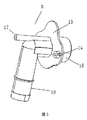
第2水道管15は段付管であり、第1水道管16および第2水道管15の接続部分から第2水道管の開口に向かって、管径は段階的に大きくなる。空気管17の第1開口は第2水道管15の段付面上に位置して、空気管は第2水道管と通じ、空気管の第2開口は出水管外に位置する。
The
空気管の第1開口は、第2水道管の段付面上における、第1水道管および第2水道管内の夾角から最も離れた位置に位置し、つまり空気管の第1開口は第2水道管の段付面上で、屈曲部の外側に近い位置に位置する。図4に示すように、排水のサイフォン防止装置を直立して据え、第2水道管15が第1水道管16の上方に位置するとき、空気管は第2水道管の最上部に位置する。
The first opening of the air pipe is located on the stepped surface of the second water pipe at a position farthest from the depression angle in the first water pipe and the second water pipe, that is, the first opening of the air pipe is the second water pipe. It is located on the stepped surface of the tube at a position close to the outside of the bent portion. As shown in FIG. 4, when the drainage siphon prevention device is installed upright and the
第1水道管および第2水道管の屈曲構造は、流体分析により、水流の圧力が比較的均等に分布する状態から、空気管の一側に近づくと圧力が小さくなるように変化することがわかる。水圧が大きいため、水流が空気管を通って逆流するのを効果的に防止する。 The bent structure of the first water pipe and the second water pipe changes from a state where the pressure of the water flow is relatively evenly distributed by fluid analysis so that the pressure decreases as it approaches one side of the air pipe. . The high water pressure effectively prevents the water flow from flowing back through the air pipe.
本実施例において、図2、3、4に示すように、空気管および第2水道管は平行に設置される。第2水道管の最上部に比較的厚い壁を有し、第2水道管の壁中に軸方向の貫通孔が空気管として設けられ、空気管の一部分は第2水道管中に包まれる。空気管の1つの開口は第2水道管と通じ、この開口に近い部分は第2水道管の内部に位置し、空気管のこの開口から離れた部分は出水管外に伸びる。その他の実施例において、空気管は第2水道管外に位置することもできるが、接続部分を介し、第2水道管と接続されて通じる。 In the present embodiment, as shown in FIGS. 2, 3, and 4, the air pipe and the second water pipe are installed in parallel. The uppermost part of the second water pipe has a relatively thick wall, an axial through hole is provided as an air pipe in the wall of the second water pipe, and a part of the air pipe is enclosed in the second water pipe. One opening of the air pipe communicates with the second water pipe, a portion close to this opening is located inside the second water pipe, and a portion away from this opening of the air pipe extends outside the water discharge pipe. In other embodiments, the air pipe can be located outside the second water pipe, but is connected to the second water pipe via the connecting portion.
図4に示すように、空気管17の内径は段付孔の異径構造であり、大径部分20および小径部分21の2つの部分からなる。第2水道管の開口部分に近い空気管の内径が最も小さく、第2水道管の開口部分から離れた空気管の内径は大きく、空気管の大径部分の長さは小径部分の長さより長い。このような構造は生産が容易である。該構造は、気体が空気管から第2水道管に容易に進入するが、第2水道管内の水が空気管に進入するのは容易ではない。
As shown in FIG. 4, the inner diameter of the
第1水道管16の取水口部分に外径面取り部19が設けられ、第1水道管の外壁に突起18が設けられる。第2水道管に、第2水道管の中心軸に垂直であるリム13が設けられ、リムに固定孔14とする貫通孔が設けられる。本装置をその他の設備と固定するのに便利である。
An outer diameter chamfered
実施例2
本実施例および実施例1の違いは次の通りである。図5、6、7に示すように、空気管の大径部分はより長く、小径部分はより短い。空気管は第2水道管の中心軸からより離れて、より外側に寄り、第2水道管の流路に割り込まない。
Example 2
The difference between the present embodiment and the first embodiment is as follows. As shown in FIGS. 5, 6, and 7, the large diameter portion of the air tube is longer and the smaller diameter portion is shorter. The air pipe is further away from the central axis of the second water pipe and is closer to the outside, and does not interrupt the flow path of the second water pipe.
実施例3
本実施例の前記洗濯機は、実施例1または2に記載の排水のサイフォン防止装置が取り付けられる。
Example 3
The washing machine of the present embodiment is attached with the drainage siphon prevention device described in the first or second embodiment.
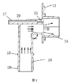
排水のサイフォン防止装置を取り付けた洗濯機は、図1に示すように、内ドラム、外ドラム2、筐体1、排水のサイフォン防止装置8を含み、内ドラムは外ドラム中に取り付けられる。外ドラムはサスペンションスプリングにより筐体内部に吊るされ、サスペンションスプリング10の上端は洗濯機筐体の2つの側面板上部に吊るされ、外ドラムの下部は減衰ダンパ12により支持される。外ドラム開口はラバークッション11と接続され、ラバークッション11は筐体の前面板に接続される。図は、本発明の排水のサイフォン防止装置を取り付けた洗濯機の内部構造をより明確に示すため、前面板を示していない。
As shown in FIG. 1, the washing machine to which the drainage siphon prevention device is attached includes an inner drum, an
排水のサイフォン防止装置8は、筐体1に固定される。図2、3、4に示すように、排水のサイフォン防止装置は出水管および空気管17を含み、出水管は相互に接続する第1水道管16および第2水道管15を含む。第1水道管16および第2水道管15の接続部分は屈曲部を形成し、第1水道管16および第2水道管15の間は夾角αを有する。この夾角αの範囲は90±5°である。本実施例において、この角度は90°である。第2水道管15は段付管であり、第1水道管16および第2水道管15の接続部分から第2水道管の開口に向かって、管径は段階的に大きくなる。空気管17の第1開口は第2水道管15の段付面上に位置して、空気管は第2水道管と通じる。空気管の第2開口は接続管を介して外ドラムと通じ、通じる位置は外ドラムの中心の上に位置する。本実施例において、外ドラムの最上部に外ドラムの空気口7が設置される。接続管はサイフォン防止ホース9であり、サイフォン防止ホース9は外ドラムの空気口7と接続される。
The drainage siphon
空気管の第1開口は、第2水道管の段付面上における、第1水道管および第2水道管内の夾角から最も離れた位置に位置し、つまり空気管の第1開口は第2水道管の段付面上で、屈曲部の外側に近い位置に位置する。排水のサイフォン防止装置8を取り付けるとき、排水のサイフォン防止装置は直立して据えるか、または斜めに据える。第2水道管15は第1水道管16の上方に位置し、空気管は第2水道管の最上部に位置するか、または空気管は第2水道管の中心以上に位置する。
The first opening of the air pipe is located on the stepped surface of the second water pipe at a position farthest from the depression angle in the first water pipe and the second water pipe, that is, the first opening of the air pipe is the second water pipe. It is located on the stepped surface of the tube at a position close to the outside of the bent portion. When the drainage siphon
第2水道管は異径構造であり、第1水道管の内径は第2水道管の最大内径より小さい。第2水道管の内径は、第2水道管および第1水道管の接続部分から第2水道管の開口部分に向かって、段階的に小径から大径に変化し、ベンチュリ効果が容易に生じる。空気管の第1開口は第2水道管15の段付面上に位置して、空気管は第2水道管と通じる。これにより気体が進入し、水が空気管を通って外ドラムに逆流することはない。
The second water pipe has a different diameter structure, and the inner diameter of the first water pipe is smaller than the maximum inner diameter of the second water pipe. The inner diameter of the second water pipe gradually changes from a small diameter to a large diameter from the connecting portion of the second water pipe and the first water pipe toward the opening of the second water pipe, and the venturi effect is easily generated. The first opening of the air pipe is located on the stepped surface of the
第1水道管および第2水道管の屈曲構造は、流体分析により、水流の圧力が比較的均等に分布する状態から、空気管の一側に近づくと圧力が小さくなるように変化することがわかる。水圧が大きいため、水流が空気管を通って逆流するのを効果的に防止する。 The bent structure of the first water pipe and the second water pipe changes from a state where the pressure of the water flow is relatively evenly distributed by fluid analysis so that the pressure decreases as it approaches one side of the air pipe. . The high water pressure effectively prevents the water flow from flowing back through the air pipe.
本実施例において、図2、3、4に示すように、空気管および第2水道管は平行に設置される。第2水道管の最上部に比較的厚い壁を有し、第2水道管の壁中に軸方向の貫通孔が空気管として設けられ、空気管の一部分は第2水道管中に包まれる。空気管の1つの開口は第2水道管と通じ、この開口に近い部分は第2水道管の内部に位置し、空気管のこの開口から離れた部分は出水管外に伸びる。その他の実施例において、空気管は第2水道管外に位置することもできるが、接続部分を介し、第2水道管と接続されて通じる。 In the present embodiment, as shown in FIGS. 2, 3, and 4, the air pipe and the second water pipe are installed in parallel. The uppermost part of the second water pipe has a relatively thick wall, an axial through hole is provided as an air pipe in the wall of the second water pipe, and a part of the air pipe is enclosed in the second water pipe. One opening of the air pipe communicates with the second water pipe, a portion close to this opening is located inside the second water pipe, and a portion away from this opening of the air pipe extends outside the water discharge pipe. In other embodiments, the air pipe can be located outside the second water pipe, but is connected to the second water pipe via the connecting portion.
図4に示すように、空気管17の内径は段付孔の異径構造であり、大径部分20および小径部分21の2つの部分からなる。第2水道管の開口部分に近い空気管の内径が最も小さく、第2水道管の開口部分から離れた空気管の内径は大きく、空気管の大径部分の長さは小径部分の長さより長い。このような構造は生産が容易である。該構造は、気体が空気管から第2水道管に容易に進入するが、第2水道管内の水が空気管に進入するのは容易ではない。
As shown in FIG. 4, the inner diameter of the
出水管の屈曲構造、第2水道管の異径構造、空気管の異径構造、さらに空気管の第1開口が第2水道管の段付面上で、屈曲部の外側に近い位置に位置する構造により、空気管部分の水圧は低く、排水時、水圧により汚れた水が空気管を通って洗濯外ドラム内に逆流するのを効果的に防止する。 The bent structure of the outlet pipe, the different diameter structure of the second water pipe, the different diameter structure of the air pipe, and the first opening of the air pipe is located on the stepped surface of the second water pipe near the outside of the bent portion. With this structure, the water pressure in the air pipe portion is low, and at the time of drainage, it is possible to effectively prevent water contaminated by the water pressure from flowing back into the drum outside the laundry through the air pipe.
排水のサイフォン防止装置における第1水道管16の開口、すなわち取水口部分に外径面取り部19が設けられ、第1水道管の外壁に突起18が設けられる。第1水道管の取水口は排水ホース5と接続されるが、面取りにより排水ホースの挿入は容易であり、突起構造は挿入する深さの定位に役立つ。排水ホース5のもう一端は排水ポンプ4と接続され、排水ポンプ4は排水管3を介して外ドラム2と接続される。排水のサイフォン防止装置における第2水道管の開口は、洗濯機筐体の外部に設置される排水ホースと接続される。
An outer diameter chamfered
第2水道管に、第2水道管の中心軸に垂直であるリム13が設けられる。リムは洗濯機筐体の背面板と接続され、両者の接触面積が増大する。リムに固定孔14とする貫通孔が設けられ、ネジを貫通孔に通すことにより、排水のサイフォン防止装置を洗濯機の筐体に固定する。
The second water pipe is provided with a
外ドラム上部に取水管6が設置され、該取水管6は洗剤ケースと接続される。取水バルブから洗剤ケースに取水され、洗剤は該取水管6を介して外ドラムに投入される。
A
外ドラムの最底部に排水管3が設置され、排水管3は排水ポンプ4と接続される。排水ポンプは排水ホース5と接続され、排水のサイフォン防止装置を介して、水を洗濯機外部に排出する。
A drain pipe 3 is installed at the bottom of the outer drum, and the drain pipe 3 is connected to a drain pump 4. The drainage pump is connected to the
本発明の実施例における排水のサイフォン防止装置を取り付けた洗濯機は、洗濯機筐体の屈折部分の空間を効果的に利用して、排水ホース5を配置する。排水のサイフォン防止装置を洗濯機筐体の背面板に固定する高さについて、この高さは外ドラムの中心位置の高さより高く、洗濯機筐体の最高高度より低い。設計上、洗濯機における排水管の最高高度の適合性を確実に保証した。洗濯機の排水が完了すると、たとえ排水のサイフォン防止装置の第2水道管に接続される排水ホース、すなわち洗濯機外の排水ホースの末端が水に浸かっていても、排水ポンプは動作を停止する。サイフォンにより逆流すると、サイフォン防止ホースは排水のサイフォン防止装置および外ドラムと通じており、外ドラムの空気が排水のサイフォン防止装置に進入する。これによりサイフォンが停止し、水が逆流して外ドラムに進入することはない。
In the washing machine equipped with the siphon prevention device for drainage in the embodiment of the present invention, the
上記実施例における実施案はさらに組み合わせるか、または置換することができ、さらに実施例は本発明の好ましい実施例を記載したに過ぎず、本発明の構想および範囲を限定しない。本発明の設計の発想を逸脱しない前提で、当業者が本発明の技術案に対して行う各種の変更および改良は、いずれも本発明の保護範囲に属する。 The implementations in the above examples can be further combined or replaced, and the examples merely describe preferred embodiments of the present invention and do not limit the concept and scope of the present invention. Any modifications and improvements made by those skilled in the art to the technical solution of the present invention without departing from the design concept of the present invention belong to the protection scope of the present invention.
1 筐体
2 外ドラム
3 排水管
4 排水ポンプ
5 排水ホース
6 取水管
7 外ドラムの空気口
8 排水のサイフォン防止装置
9 サイフォン防止ホース
10 サスペンションスプリング
11 ラバークッション
12 減衰ダンパ
13 リム
14 固定孔
15 第2水道管
16 第1水道管
17 空気管
18 突起
19 面取り部
20 大径部分
21 小径部分
DESCRIPTION OF
Claims (10)
出水管は相互に接続する第1水道管および第2水道管を含み、第2水道管の少なくとも一部の管径は第1水道管の管径より大きく、
空気管の一端は第2水道管と通じ、空気管が第2水道管と通じる部分は、第2水道管の径方向面に位置することを特徴とする排水のサイフォン防止装置。 Including drain pipe and air pipe,
The outlet pipe includes a first water pipe and a second water pipe connected to each other, and the diameter of at least a part of the second water pipe is larger than the diameter of the first water pipe,
An apparatus for preventing siphoning of drainage, wherein one end of the air pipe communicates with the second water pipe, and a portion where the air pipe communicates with the second water pipe is located on a radial surface of the second water pipe.
ことを特徴とする、請求項1に記載の排水のサイフォン防止装置。 The drainage according to claim 1, wherein a connecting portion of the first water pipe and the second water pipe forms a bent portion, and a depression angle of a constant angle is formed between the first water pipe and the second water pipe. Siphon prevention device.
ことを特徴とする、請求項1または2に記載の排水のサイフォン防止装置。 The second water pipe is a stepped pipe, and the diameter of the pipe gradually increases from the connecting portion of the first water pipe and the second water pipe toward the opening of the second water pipe, and the first opening of the air pipe is The air pipe is located on the stepped surface of the second water pipe, the air pipe communicates with the second water pipe, and the second opening of the air pipe is located outside the water discharge pipe. Siphon prevention device for drainage.
内ドラムは外ドラム中に取り付けられ、内ドラム、外ドラムは筐体中に取り付けられ、外ドラムはサスペンションスプリングにより筐体内部に吊るされ、排水のサイフォン防止装置は筐体に固定され、
排水のサイフォン防止装置における空気管の1つの開口は、排水のサイフォン防止装置の第2水道管と通じ、もう1つの開口は接続管を介して外ドラムと通じ、通じる位置は外ドラムの中心の上に位置し、
排水のサイフォン防止装置における第1水道管の開口は、排水ホースを介して排水ポンプと接続され、排水ポンプは排水管を介して外ドラムと接続され、
排水のサイフォン防止装置における第2水道管の開口は、洗濯機筐体の外部に設置される排水ホースと接続され;
排水のサイフォン防止装置の空気管は、排水のサイフォン防止装置における第2水道管の中心軸の上方に位置することを特徴とする洗濯機。 A washing machine equipped with the drainage siphon prevention device according to any one of claims 1 to 8, comprising an inner drum, an outer drum, a housing, a drainage pump, a drainage siphon prevention device,
The inner drum is mounted in the outer drum, the inner drum and the outer drum are mounted in the housing, the outer drum is suspended inside the housing by a suspension spring, the siphon prevention device for drainage is fixed to the housing,
One opening of the air pipe in the drainage siphon prevention device communicates with the second water pipe of the drainage siphon prevention device, and the other opening communicates with the outer drum through the connection pipe, and the position of communication is at the center of the outer drum. Located on top
The opening of the first water pipe in the drainage siphon prevention device is connected to a drainage pump via a drainage hose, the drainage pump is connected to an outer drum via a drainage pipe,
The opening of the second water pipe in the drainage siphon prevention device is connected to a drainage hose installed outside the washing machine housing;
The air pipe of the drainage siphon prevention device is located above the central axis of the second water pipe in the drainage siphon prevention device.
Applications Claiming Priority (3)
| Application Number | Priority Date | Filing Date | Title |
|---|---|---|---|
| CN201510217762.1A CN106192310B (en) | 2015-04-30 | 2015-04-30 | Drainage anti-siphon device and washing machine provided with same |
| CN201510217762.1 | 2015-04-30 | ||
| PCT/CN2016/079402 WO2016173408A1 (en) | 2015-04-30 | 2016-04-15 | Anti-siphon drainage device and washing machine provided with same |
Publications (1)
| Publication Number | Publication Date |
|---|---|
| JP2018514308A true JP2018514308A (en) | 2018-06-07 |
Family
ID=57198936
Family Applications (1)
| Application Number | Title | Priority Date | Filing Date |
|---|---|---|---|
| JP2017556714A Pending JP2018514308A (en) | 2015-04-30 | 2016-04-15 | Siphon prevention device for drainage and washing machine equipped with this device |
Country Status (6)
| Country | Link |
|---|---|
| US (1) | US10815608B2 (en) |
| EP (1) | EP3290569B1 (en) |
| JP (1) | JP2018514308A (en) |
| KR (1) | KR101977633B1 (en) |
| CN (1) | CN106192310B (en) |
| WO (1) | WO2016173408A1 (en) |
Families Citing this family (3)
| Publication number | Priority date | Publication date | Assignee | Title |
|---|---|---|---|---|
| CN109744973B (en) * | 2017-11-08 | 2021-07-16 | 天津衣联网生态科技有限公司 | Washing equipment with auxiliary cleaning function |
| CN111394944A (en) * | 2019-01-02 | 2020-07-10 | 青岛海尔洗衣机有限公司 | Wall-mounted washing machine |
| CN111826897A (en) * | 2019-04-16 | 2020-10-27 | 青岛海尔滚筒洗衣机有限公司 | Drum washing machine and outer drum thereof |
Family Cites Families (11)
| Publication number | Priority date | Publication date | Assignee | Title |
|---|---|---|---|---|
| AU466699B2 (en) * | 1971-12-24 | 1975-11-06 | BRIAN MURPHY and JOHN FRANCIS KEATING KERRY | Improved anti-siphon fitting |
| JPS55115691U (en) * | 1979-02-13 | 1980-08-15 | ||
| JP2506161Y2 (en) | 1990-12-19 | 1996-08-07 | 株式会社イナックス | Ball tap structure |
| KR20000032394A (en) * | 1998-11-14 | 2000-06-15 | 구자홍 | Structure for draining vapor and bubble of washing machine |
| KR20030092186A (en) | 2002-05-27 | 2003-12-06 | 엘지전자 주식회사 | drain unit fixing structure of drum washing machine |
| KR100751763B1 (en) * | 2005-12-16 | 2007-08-24 | 주식회사 대우일렉트로닉스 | Cuff structure of drum type washing machine |
| KR20070082377A (en) * | 2006-02-16 | 2007-08-21 | 엘지전자 주식회사 | Siphon breaking structure of washing machine |
| KR100792522B1 (en) * | 2007-02-01 | 2008-01-10 | 삼성전자주식회사 | Washing machine |
| KR101498058B1 (en) * | 2009-01-23 | 2015-03-03 | 엘지전자 주식회사 | Drumtype washing machine |
| CN102292489B (en) * | 2009-02-23 | 2013-05-01 | Lg电子株式会社 | Washing machine |
| KR102146376B1 (en) * | 2013-08-07 | 2020-08-21 | 삼성전자주식회사 | Washing Machine |
-
2015
- 2015-04-30 CN CN201510217762.1A patent/CN106192310B/en active Active
-
2016
- 2016-04-15 KR KR1020177033873A patent/KR101977633B1/en active IP Right Grant
- 2016-04-15 EP EP16785839.8A patent/EP3290569B1/en active Active
- 2016-04-15 JP JP2017556714A patent/JP2018514308A/en active Pending
- 2016-04-15 WO PCT/CN2016/079402 patent/WO2016173408A1/en active Application Filing
- 2016-04-15 US US15/570,057 patent/US10815608B2/en active Active
Also Published As
| Publication number | Publication date |
|---|---|
| KR101977633B1 (en) | 2019-05-14 |
| US10815608B2 (en) | 2020-10-27 |
| EP3290569B1 (en) | 2021-07-28 |
| EP3290569A1 (en) | 2018-03-07 |
| EP3290569A4 (en) | 2018-05-02 |
| WO2016173408A1 (en) | 2016-11-03 |
| CN106192310B (en) | 2019-12-27 |
| US20180127913A1 (en) | 2018-05-10 |
| KR20170138554A (en) | 2017-12-15 |
| CN106192310A (en) | 2016-12-07 |
Similar Documents
| Publication | Publication Date | Title |
|---|---|---|
| CN108478142B (en) | Dish washing machine | |
| JP2018514308A (en) | Siphon prevention device for drainage and washing machine equipped with this device | |
| JP2014169784A (en) | Vacuum breaker, chair toilet bowl automatic water flushing system and electronic chair toilet bowl | |
| CN107059329B (en) | Foam generator assembly and washing machine | |
| CN105986427A (en) | Washing machine dual-end drainage pump | |
| CN108866945B (en) | Washing machine outer barrel and washing machine | |
| JP2014196636A (en) | Water closet and construction method for the same | |
| CN208152203U (en) | A kind of floor drain for washing machine component | |
| TWM599875U (en) | Confluence drainage device | |
| CN112878004B (en) | Washing machine | |
| CN207633449U (en) | A kind of outlet device | |
| JP2009168089A (en) | Exhaust valve | |
| CN110960169A (en) | Cleaning machine | |
| TWI732478B (en) | Confluence drainage device | |
| CN204959944U (en) | Floor drain with deodorizing function | |
| CN109868886A (en) | A kind of floor drain for washing machine component | |
| CN205781126U (en) | A kind of draining pump noise reduction check valve structure | |
| CN219422744U (en) | Integrated dish-washing machine | |
| CN214496867U (en) | Washing machine | |
| CN109424061A (en) | A kind of novel cleanable formula anti-blocking deodorant floor drain structure | |
| CN105840543B (en) | Drainage pump assembly and washing machine with same | |
| CN219439022U (en) | Sink device for dish-washing machine and dish-washing machine | |
| JP2009019731A (en) | Exhaust valve | |
| CN207537750U (en) | A kind of base assembly of washing machine | |
| CN110952281B (en) | Wall-mounted washing machine |
Legal Events
| Date | Code | Title | Description |
|---|---|---|---|
| A621 | Written request for application examination |
Free format text: JAPANESE INTERMEDIATE CODE: A621 Effective date: 20180417 |
|
| A977 | Report on retrieval |
Free format text: JAPANESE INTERMEDIATE CODE: A971007 Effective date: 20190515 |
|
| A131 | Notification of reasons for refusal |
Free format text: JAPANESE INTERMEDIATE CODE: A131 Effective date: 20190604 |
|
| A02 | Decision of refusal |
Free format text: JAPANESE INTERMEDIATE CODE: A02 Effective date: 20200107 |