JP2018513716A - Wearable devices used in two stages - Google Patents
Wearable devices used in two stages Download PDFInfo
- Publication number
- JP2018513716A JP2018513716A JP2017548255A JP2017548255A JP2018513716A JP 2018513716 A JP2018513716 A JP 2018513716A JP 2017548255 A JP2017548255 A JP 2017548255A JP 2017548255 A JP2017548255 A JP 2017548255A JP 2018513716 A JP2018513716 A JP 2018513716A
- Authority
- JP
- Japan
- Prior art keywords
- wearable band
- display module
- wearable
- band
- sleep
- Prior art date
- Legal status (The legal status is an assumption and is not a legal conclusion. Google has not performed a legal analysis and makes no representation as to the accuracy of the status listed.)
- Pending
Links
Images


Classifications
-
- A—HUMAN NECESSITIES
- A61—MEDICAL OR VETERINARY SCIENCE; HYGIENE
- A61B—DIAGNOSIS; SURGERY; IDENTIFICATION
- A61B5/00—Measuring for diagnostic purposes; Identification of persons
- A61B5/02—Detecting, measuring or recording pulse, heart rate, blood pressure or blood flow; Combined pulse/heart-rate/blood pressure determination; Evaluating a cardiovascular condition not otherwise provided for, e.g. using combinations of techniques provided for in this group with electrocardiography or electroauscultation; Heart catheters for measuring blood pressure
- A61B5/024—Detecting, measuring or recording pulse rate or heart rate
- A61B5/02438—Detecting, measuring or recording pulse rate or heart rate with portable devices, e.g. worn by the patient
-
- A—HUMAN NECESSITIES
- A44—HABERDASHERY; JEWELLERY
- A44C—PERSONAL ADORNMENTS, e.g. JEWELLERY; COINS
- A44C5/00—Bracelets; Wrist-watch straps; Fastenings for bracelets or wrist-watch straps
- A44C5/14—Bracelets; Wrist-watch straps; Fastenings for bracelets or wrist-watch straps characterised by the way of fastening to a wrist-watch or the like
-
- A—HUMAN NECESSITIES
- A61—MEDICAL OR VETERINARY SCIENCE; HYGIENE
- A61B—DIAGNOSIS; SURGERY; IDENTIFICATION
- A61B5/00—Measuring for diagnostic purposes; Identification of persons
- A61B5/103—Detecting, measuring or recording devices for testing the shape, pattern, colour, size or movement of the body or parts thereof, for diagnostic purposes
- A61B5/11—Measuring movement of the entire body or parts thereof, e.g. head or hand tremor, mobility of a limb
- A61B5/1118—Determining activity level
-
- A—HUMAN NECESSITIES
- A61—MEDICAL OR VETERINARY SCIENCE; HYGIENE
- A61B—DIAGNOSIS; SURGERY; IDENTIFICATION
- A61B5/00—Measuring for diagnostic purposes; Identification of persons
- A61B5/48—Other medical applications
- A61B5/4806—Sleep evaluation
-
- A—HUMAN NECESSITIES
- A61—MEDICAL OR VETERINARY SCIENCE; HYGIENE
- A61B—DIAGNOSIS; SURGERY; IDENTIFICATION
- A61B5/00—Measuring for diagnostic purposes; Identification of persons
- A61B5/68—Arrangements of detecting, measuring or recording means, e.g. sensors, in relation to patient
- A61B5/6801—Arrangements of detecting, measuring or recording means, e.g. sensors, in relation to patient specially adapted to be attached to or worn on the body surface
- A61B5/6802—Sensor mounted on worn items
- A61B5/681—Wristwatch-type devices
-
- A—HUMAN NECESSITIES
- A61—MEDICAL OR VETERINARY SCIENCE; HYGIENE
- A61B—DIAGNOSIS; SURGERY; IDENTIFICATION
- A61B5/00—Measuring for diagnostic purposes; Identification of persons
- A61B5/68—Arrangements of detecting, measuring or recording means, e.g. sensors, in relation to patient
- A61B5/6801—Arrangements of detecting, measuring or recording means, e.g. sensors, in relation to patient specially adapted to be attached to or worn on the body surface
- A61B5/6813—Specially adapted to be attached to a specific body part
- A61B5/6824—Arm or wrist
-
- A—HUMAN NECESSITIES
- A61—MEDICAL OR VETERINARY SCIENCE; HYGIENE
- A61B—DIAGNOSIS; SURGERY; IDENTIFICATION
- A61B5/00—Measuring for diagnostic purposes; Identification of persons
- A61B5/74—Details of notification to user or communication with user or patient ; user input means
- A61B5/742—Details of notification to user or communication with user or patient ; user input means using visual displays
- A61B5/7435—Displaying user selection data, e.g. icons in a graphical user interface
-
- G—PHYSICS
- G06—COMPUTING; CALCULATING OR COUNTING
- G06F—ELECTRIC DIGITAL DATA PROCESSING
- G06F1/00—Details not covered by groups G06F3/00 - G06F13/00 and G06F21/00
- G06F1/16—Constructional details or arrangements
- G06F1/1613—Constructional details or arrangements for portable computers
- G06F1/163—Wearable computers, e.g. on a belt
-
- G—PHYSICS
- G06—COMPUTING; CALCULATING OR COUNTING
- G06F—ELECTRIC DIGITAL DATA PROCESSING
- G06F1/00—Details not covered by groups G06F3/00 - G06F13/00 and G06F21/00
- G06F1/16—Constructional details or arrangements
- G06F1/1613—Constructional details or arrangements for portable computers
- G06F1/1633—Constructional details or arrangements of portable computers not specific to the type of enclosures covered by groups G06F1/1615 - G06F1/1626
- G06F1/1635—Details related to the integration of battery packs and other power supplies such as fuel cells or integrated AC adapter
-
- G—PHYSICS
- G06—COMPUTING; CALCULATING OR COUNTING
- G06F—ELECTRIC DIGITAL DATA PROCESSING
- G06F1/00—Details not covered by groups G06F3/00 - G06F13/00 and G06F21/00
- G06F1/16—Constructional details or arrangements
- G06F1/1613—Constructional details or arrangements for portable computers
- G06F1/1633—Constructional details or arrangements of portable computers not specific to the type of enclosures covered by groups G06F1/1615 - G06F1/1626
- G06F1/1637—Details related to the display arrangement, including those related to the mounting of the display in the housing
- G06F1/1654—Details related to the display arrangement, including those related to the mounting of the display in the housing the display being detachable, e.g. for remote use
-
- G—PHYSICS
- G06—COMPUTING; CALCULATING OR COUNTING
- G06F—ELECTRIC DIGITAL DATA PROCESSING
- G06F1/00—Details not covered by groups G06F3/00 - G06F13/00 and G06F21/00
- G06F1/26—Power supply means, e.g. regulation thereof
- G06F1/266—Arrangements to supply power to external peripherals either directly from the computer or under computer control, e.g. supply of power through the communication port, computer controlled power-strips
-
- A—HUMAN NECESSITIES
- A61—MEDICAL OR VETERINARY SCIENCE; HYGIENE
- A61B—DIAGNOSIS; SURGERY; IDENTIFICATION
- A61B2560/00—Constructional details of operational features of apparatus; Accessories for medical measuring apparatus
- A61B2560/02—Operational features
- A61B2560/0266—Operational features for monitoring or limiting apparatus function
-
- A—HUMAN NECESSITIES
- A61—MEDICAL OR VETERINARY SCIENCE; HYGIENE
- A61B—DIAGNOSIS; SURGERY; IDENTIFICATION
- A61B2560/00—Constructional details of operational features of apparatus; Accessories for medical measuring apparatus
- A61B2560/02—Operational features
- A61B2560/029—Operational features adapted for auto-initiation
-
- A—HUMAN NECESSITIES
- A61—MEDICAL OR VETERINARY SCIENCE; HYGIENE
- A61B—DIAGNOSIS; SURGERY; IDENTIFICATION
- A61B2560/00—Constructional details of operational features of apparatus; Accessories for medical measuring apparatus
- A61B2560/04—Constructional details of apparatus
- A61B2560/0443—Modular apparatus
-
- A—HUMAN NECESSITIES
- A61—MEDICAL OR VETERINARY SCIENCE; HYGIENE
- A61B—DIAGNOSIS; SURGERY; IDENTIFICATION
- A61B2562/00—Details of sensors; Constructional details of sensor housings or probes; Accessories for sensors
- A61B2562/16—Details of sensor housings or probes; Details of structural supports for sensors
- A61B2562/164—Details of sensor housings or probes; Details of structural supports for sensors the sensor is mounted in or on a conformable substrate or carrier
-
- A—HUMAN NECESSITIES
- A61—MEDICAL OR VETERINARY SCIENCE; HYGIENE
- A61B—DIAGNOSIS; SURGERY; IDENTIFICATION
- A61B5/00—Measuring for diagnostic purposes; Identification of persons
- A61B5/0002—Remote monitoring of patients using telemetry, e.g. transmission of vital signals via a communication network
- A61B5/0015—Remote monitoring of patients using telemetry, e.g. transmission of vital signals via a communication network characterised by features of the telemetry system
- A61B5/0022—Monitoring a patient using a global network, e.g. telephone networks, internet
-
- A—HUMAN NECESSITIES
- A61—MEDICAL OR VETERINARY SCIENCE; HYGIENE
- A61B—DIAGNOSIS; SURGERY; IDENTIFICATION
- A61B5/00—Measuring for diagnostic purposes; Identification of persons
- A61B5/02—Detecting, measuring or recording pulse, heart rate, blood pressure or blood flow; Combined pulse/heart-rate/blood pressure determination; Evaluating a cardiovascular condition not otherwise provided for, e.g. using combinations of techniques provided for in this group with electrocardiography or electroauscultation; Heart catheters for measuring blood pressure
- A61B5/0205—Simultaneously evaluating both cardiovascular conditions and different types of body conditions, e.g. heart and respiratory condition
-
- A—HUMAN NECESSITIES
- A61—MEDICAL OR VETERINARY SCIENCE; HYGIENE
- A61B—DIAGNOSIS; SURGERY; IDENTIFICATION
- A61B5/00—Measuring for diagnostic purposes; Identification of persons
- A61B5/02—Detecting, measuring or recording pulse, heart rate, blood pressure or blood flow; Combined pulse/heart-rate/blood pressure determination; Evaluating a cardiovascular condition not otherwise provided for, e.g. using combinations of techniques provided for in this group with electrocardiography or electroauscultation; Heart catheters for measuring blood pressure
- A61B5/021—Measuring pressure in heart or blood vessels
- A61B5/02141—Details of apparatus construction, e.g. pump units or housings therefor, cuff pressurising systems, arrangements of fluid conduits or circuits
-
- A—HUMAN NECESSITIES
- A61—MEDICAL OR VETERINARY SCIENCE; HYGIENE
- A61B—DIAGNOSIS; SURGERY; IDENTIFICATION
- A61B5/00—Measuring for diagnostic purposes; Identification of persons
- A61B5/08—Detecting, measuring or recording devices for evaluating the respiratory organs
- A61B5/0816—Measuring devices for examining respiratory frequency
-
- A—HUMAN NECESSITIES
- A61—MEDICAL OR VETERINARY SCIENCE; HYGIENE
- A61B—DIAGNOSIS; SURGERY; IDENTIFICATION
- A61B5/00—Measuring for diagnostic purposes; Identification of persons
- A61B5/48—Other medical applications
- A61B5/4806—Sleep evaluation
- A61B5/4809—Sleep detection, i.e. determining whether a subject is asleep or not
-
- A—HUMAN NECESSITIES
- A61—MEDICAL OR VETERINARY SCIENCE; HYGIENE
- A61B—DIAGNOSIS; SURGERY; IDENTIFICATION
- A61B5/00—Measuring for diagnostic purposes; Identification of persons
- A61B5/48—Other medical applications
- A61B5/4806—Sleep evaluation
- A61B5/4812—Detecting sleep stages or cycles
-
- A—HUMAN NECESSITIES
- A61—MEDICAL OR VETERINARY SCIENCE; HYGIENE
- A61B—DIAGNOSIS; SURGERY; IDENTIFICATION
- A61B5/00—Measuring for diagnostic purposes; Identification of persons
- A61B5/48—Other medical applications
- A61B5/4806—Sleep evaluation
- A61B5/4815—Sleep quality
-
- G—PHYSICS
- G04—HOROLOGY
- G04B—MECHANICALLY-DRIVEN CLOCKS OR WATCHES; MECHANICAL PARTS OF CLOCKS OR WATCHES IN GENERAL; TIME PIECES USING THE POSITION OF THE SUN, MOON OR STARS
- G04B47/00—Time-pieces combined with other articles which do not interfere with the running or the time-keeping of the time-piece
- G04B47/06—Time-pieces combined with other articles which do not interfere with the running or the time-keeping of the time-piece with attached measuring instruments, e.g. pedometer, barometer, thermometer or compass
- G04B47/063—Time-pieces combined with other articles which do not interfere with the running or the time-keeping of the time-piece with attached measuring instruments, e.g. pedometer, barometer, thermometer or compass measuring physiological quantities, e.g. pedometers, heart-rate sensors, blood pressure gauges and the like
Abstract
二状態式ウェアラブルデバイスは、ウェアラブルバンド(例えば、時計バンド)と、ディスプレイモジュール(例えば、時計面)とを含む。「分離」状態において、ウェアラブルバンドとディスプレイモジュールとは、個別のデバイスとして動作し、ウェアラブルバンドがセンサデータ(例えば、睡眠追跡データ)を集め、振動/音響アラーム時計機能を提供する間にディスプレイモジュールはそのバッテリを充電できる。「取り付け」状態において、ウェアラブルバンドとディスプレイモジュールとは単一のデバイスとして一緒に動作し、このことは、「分離」状態中にウェアラブルバンドによって収集されたデータがディスプレイモジュールに送られて記憶され、ディスプレイモジュールのユーザインターフェースにおいて入力された睡眠設定がウェアラブルバンドのアラーム機能に反映されることを意味する。ディスプレイモジュールは、その新たに再充電されたバッテリを使用してウェアラブルバンドのバッテリを再充電し、次の夜に使用可能にすることもできる。A two-state wearable device includes a wearable band (eg, watch band) and a display module (eg, watch face). In the “isolated” state, the wearable band and display module operate as separate devices, while the wearable band collects sensor data (eg, sleep tracking data) and provides a vibration / acoustic alarm clock function. The battery can be charged. In the “attached” state, the wearable band and the display module operate together as a single device, which means that data collected by the wearable band during the “isolated” state is sent to the display module for storage, This means that the sleep setting input in the user interface of the display module is reflected in the alarm function of the wearable band. The display module can also use its newly recharged battery to recharge the wearable band battery and make it available the next night.
Description
本発明は、概して、ウェアラブル技術に関する。より具体的には、本発明は、ディスプレイモジュールを解除可能に取り付ける機能的ウェアラブルバンドを含むウェアラブルデバイスに関する。 The present invention generally relates to wearable technology. More specifically, the present invention relates to a wearable device that includes a functional wearable band for releasably attaching a display module.
ウェアラブル電子デバイス、又は本明細書において使用されるとき、ウェアラブル技術は、ユーザによって装着される様々な目立たないセンサを介したデータの取得を提供可能な電子システムの新しい部門である。センサは、例えば環境、ユーザの活動又はユーザの健康状態についての情報を集める。しかしながら、収集されたデータの協調、計算、通信、プライバシー、セキュリティ、及び提示に関連する大きな課題がある。更には、バッテリ技術の現在の状態に基づく電力管理に関連する課題がある。更には、センサによって集められたデータをエンドユーザに有用なもの又はエンドユーザに関連したものにするために、データの分析が必要とされる。いくつかの場合において、センサによって集められたデータを補うために情報の追加的なソースが使用される。ウェアラブル技術が提示する多くの課題は、ハードウェア及びソフトウェアにおいて新しい設計を必要とする。 Wearable electronic devices, or as used herein, wearable technology is a new division of electronic systems that can provide data acquisition via various inconspicuous sensors worn by a user. The sensor collects information about, for example, the environment, user activity or user health. However, there are significant challenges associated with the collaboration, computation, communication, privacy, security, and presentation of collected data. Furthermore, there are challenges associated with power management based on the current state of battery technology. Furthermore, analysis of the data is required in order to make the data collected by the sensor useful to or related to the end user. In some cases, additional sources of information are used to supplement the data collected by the sensors. Many challenges presented by wearable technology require new designs in hardware and software.
ウェアラブル技術は、身体に装着され得又は個人の衣服及びアクセサリに取り付けられ若しくは埋め込まれ得、消費者市場に現在存在する任意のタイプのモバイル電子デバイスを含む。ウェアラブル技術に関連付けられたプロセッサ及びセンサは、情報を表示、処理又は収集可能である。そのようなウェアラブル技術は、ユーザの健康の監視及び他のタイプのデータ並びに統計の収集など、様々な領域で使用されている。これらのタイプのデバイスは、大衆が簡単に利用でき、消費者によって容易に購入されている。健康関連の分野におけるいくつかのウェアラブル技術の例としては、FitBit、NikeFuel Band、Jawbone Up及びApple Watchなどがある。 Wearable technology includes any type of mobile electronic device that can be worn on the body or attached or embedded in personal clothing and accessories and currently exists in the consumer market. Processors and sensors associated with wearable technology can display, process or collect information. Such wearable technologies are used in various areas such as monitoring user health and collecting other types of data and statistics. These types of devices are easily available to the masses and are easily purchased by consumers. Some examples of wearable technologies in the health-related field include FitBit, Nicke Fuel Band, Jawbone Up, and Apple Watch.
典型的には、ウェアラブルデバイスは、ユーザについてのデータを集めるために使用され得る。例えば、ウェアラブルデバイスは、1つ又は複数のセンサを使用して、日中にはユーザの健康パラメータ(例えば、心拍数)を、夜間にユーザが睡眠している間には睡眠パターンに関するデータを監視することができる。従って、多くのウェアラブルデバイスは、一日のどの時点においても有用な機能を提供する。しかしながら、ウェアラブルデバイスは、典型的には小型のデバイスであり、時には24時間未満の使用の後に充電を必要とするような、頻繁に充電されなければならない小型のバッテリを有する。結果として、そのようなウェアラブルデバイスのユーザは、典型的には、デバイスを充電するために、ウェアラブルデバイスの(例えば、睡眠パターンデータを生成するための)夜間の使用をあきらめるか、又はウェアラブルデバイスを(例えば、睡眠パターンデータを生成するために)夜間に使用するが日中にはウェアラブルデバイスを充電するか、若しくは、ことによると日中にバッテリ充電が切れるか、を決めなければならない。 Typically, wearable devices can be used to gather data about users. For example, a wearable device uses one or more sensors to monitor a user's health parameters (eg, heart rate) during the day and sleep pattern data while the user is sleeping at night. can do. Thus, many wearable devices provide useful functionality at any point in the day. However, wearable devices are typically small devices and have small batteries that must be charged frequently, sometimes requiring charging after less than 24 hours of use. As a result, users of such wearable devices typically give up wearable devices at night (eg, to generate sleep pattern data) or charge wearable devices to charge the device. You must decide whether to use the wearable device during the day but to charge the wearable device during the day (or possibly to drain the battery during the day) (eg, to generate sleep pattern data).
それ故、本明細書において開示される様々な実施形態は、例えば時計バンドなどのウェアラブルバンドと、例えば時計面などのディスプレイモジュールとを含んだ、二状態式ウェアラブルデバイス(two−state wearable device)を対象とする。「分離」状態において、ウェアラブルバンドとディスプレイモジュールとは、個別のデバイスとして動作し、ウェアラブルバンドがセンサデータ(例えば、睡眠追跡データ)を集め、及び/又は振動/音響アラーム時計機能を提供する間にディスプレイモジュールはそのバッテリを充電できる。「取り付け」状態において、ウェアラブルバンドとディスプレイモジュールとは単一のデバイスとして一緒に動作し、「分離」状態中にウェアラブルバンドによって収集されたデータがディスプレイモジュールに送られて記憶され、ディスプレイモジュールのユーザインターフェースにおいて入力された睡眠設定がウェアラブルバンドのアラーム機能に反映される。一実施形態において、ディスプレイモジュールは、その新たに再充電されたバッテリを使用してウェアラブルバンドのバッテリを再充電し、次の夜に使用可能にすることもできる。 Therefore, various embodiments disclosed herein include a two-state wearable device that includes a wearable band such as a watch band and a display module such as a watch face. set to target. In the “isolated” state, the wearable band and the display module operate as separate devices while the wearable band collects sensor data (eg, sleep tracking data) and / or provides a vibration / acoustic alarm clock function. The display module can charge the battery. In the “attached” state, the wearable band and the display module operate together as a single device, and the data collected by the wearable band during the “separated” state is sent to the display module for storage and the display module user. The sleep setting input in the interface is reflected in the alarm function of the wearable band. In one embodiment, the display module can also use its newly recharged battery to recharge the wearable band battery and make it available the next night.
一実施形態によると、2つの状態で使用されるウェアラブルデバイスが提供され、ウェアラブルデバイスは、ウェアラブルバンドが取り付け状態と分離状態との間で構成可能であるようにディスプレイモジュールを解除可能に取り付けるように構成されるウェアラブルバンドを備え、取り付け状態において、ウェアラブルバンドはディスプレイモジュールに取り付けられるとともにディスプレイモジュールと通信し、分離状態において、ウェアラブルバンドはディスプレイモジュールから分離及び離間されていて、ウェアラブルバンドは、プログラムインストラクションを実行するように構成され、ウェアラブルバンドが分離状態又は取り付け状態にあるときを判定するように構成されたウェアラブルバンドプロセッサと;少なくとも分離状態にあるときにウェアラブルバンドに電力供給し、外部電源から充電を受けるように構成されたウェアラブルバンドバッテリと;少なくとも分離状態にあるときに少なくとも1つのセンサ測定を行うように構成された少なくとも1つのウェアラブルバンドセンサと;少なくとも分離状態にあるときにウェアラブルバンドセンサ測定値の少なくとも一部を記憶するように構成されたウェアラブルバンドメモリと;少なくとも取り付け状態にあるときに、ウェアラブルバンドセンサ測定値の少なくとも一部をディスプレイモジュールに送信するために構成されたウェアラブルバンド通信インターフェースと、を備える。 According to one embodiment, a wearable device is provided that is used in two states, wherein the wearable device releasably attaches the display module such that the wearable band is configurable between an attached state and a detached state. Comprising a wearable band configured, wherein in the attached state, the wearable band is attached to and communicates with the display module, and in the detached state, the wearable band is separated and separated from the display module, and the wearable band is a program instruction. A wearable band processor configured to determine when the wearable band is in a detached state or an attached state; A wearable band battery configured to power the wearable band when receiving and to be charged from an external power source; at least one wearable configured to perform at least one sensor measurement when at least in a disconnected state A wearable band memory configured to store at least a portion of the wearable band sensor measurement value when at least in a detached state; and at least a portion of the wearable band sensor measurement value at least in an attached state. A wearable band communication interface configured to transmit to the display module.
一実施形態によると、ウェアラブルバンドに解除可能に取り付けられるように構成されているディスプレイモジュールは、プログラムインストラクションを実行するために構成され、ディスプレイモジュールがウェアラブルバンドに取り付けられているかを判定するように構成されたディスプレイモジュールプロセッサと;ウェアラブルバンドからウェアラブルバンドセンサ測定値の少なくとも一部を受信するために構成されたディスプレイモジュール通信インターフェースと;ウェアラブルバンドセンサ測定値を受信し、記憶するように構成されたディスプレイモジュールメモリと;ディスプレイモジュールに電力供給するように構成されたディスプレイモジュールバッテリと、を備える。 According to one embodiment, a display module configured to be releasably attached to a wearable band is configured to perform program instructions and configured to determine whether the display module is attached to a wearable band. A display module processor configured to receive at least a portion of the wearable band sensor measurements from the wearable band; and a display configured to receive and store the wearable band sensor measurements A module memory; and a display module battery configured to power the display module.
一実施形態によると、外部電源は、ディスプレイモジュールバッテリである。 According to one embodiment, the external power source is a display module battery.
一実施形態によると、外部電源は、外部の接続可能なバッテリである。 According to one embodiment, the external power source is an external connectable battery.
一実施形態によると、ディスプレイモジュールは、時計面である。 According to one embodiment, the display module is a watch face.
一実施形態によると、ディスプレイモジュールは、ウェアラブルバンドの少なくとも1つの設定を設定するように構成される。 According to one embodiment, the display module is configured to set at least one setting of the wearable band.
一実施形態によると、ディスプレイモジュールは、1つ又は複数のディスプレイモジュールセンサ測定を行うために構成される1つ又は複数のディスプレイモジュールセンサを更に備える。 According to one embodiment, the display module further comprises one or more display module sensors configured to perform one or more display module sensor measurements.
一実施形態によると、ウェアラブルバンドプロセッサは、ウェアラブルバンドインストラクションを実行して所定の時間にアラーム出力を生成するように更に構成され、アラーム出力は、ウェアラブルバンドのバイブレータの振動又はウェアラブルバンドのスピーカからの音響出力のうちの1つである。 According to one embodiment, the wearable band processor is further configured to execute a wearable band instruction to generate an alarm output at a predetermined time, wherein the alarm output is from a vibration of the wearable band vibrator or from a wearable band speaker. One of the acoustic outputs.
一実施形態によると、ウェアラブルバンドプロセッサは、ウェアラブルバンドインストラクションを実行して、少なくとも所定のアラーム時刻を含む受信した睡眠設定入力を処理し、ディスプレイモジュールがウェアラブルバンドに接続されたことを判定した後、睡眠設定入力をウェアラブルバンドに送信するように更に構成される。 According to one embodiment, the wearable band processor executes the wearable band instruction to process the received sleep setting input including at least a predetermined alarm time, and after determining that the display module is connected to the wearable band, Further configured to transmit the sleep setting input to the wearable band.
一実施形態によると、ウェアラブルバンドセンサ測定は、睡眠品質、睡眠持続時間、睡眠運動、睡眠パターン、睡眠中断、睡眠脈拍、睡眠血圧、睡眠呼吸、ユーザの入眠に関連する時間値、又はユーザの起床に関連する時間値のうちの少なくとも1つに関連する睡眠測定を含む。 According to one embodiment, the wearable band sensor measurement may include sleep quality, sleep duration, sleep movement, sleep pattern, sleep interruption, sleep pulse, sleep blood pressure, sleep breathing, time value associated with user sleep, or user wake-up. A sleep measurement associated with at least one of the time values associated with.
一実施形態によると、2つのステージで使用されるウェアラブルデバイスを利用するための方法は、ウェアラブルバンドが取り付け状態と分離状態との間で構成可能であるようにディスプレイモジュールを解除可能に取り付けるように構成されるウェアラブルバンドを備え、取り付け状態において、ウェアラブルバンドはディスプレイモジュールに取り付けられるとともにディスプレイモジュールと通信し、分離状態において、ウェアラブルバンドはディスプレイモジュールから分離及び離間されており、ウェアラブルバンドは、ウェアラブルバンドプロセッサと、ウェアラブルバンドに電力供給するように構成されたウェアラブルバンドバッテリと、ウェアラブルバンドメモリと、少なくとも1つのウェアラブルバンドセンサとを備える、ウェアラブルバンドを提供するステップと;ウェアラブルバンドに含まれる少なくとも1つのウェアラブルバンドセンサによって少なくとも1つのウェアラブルバンドセンサ測定を行うステップと;ウェアラブルバンドセンサ測定値の少なくとも一部をウェアラブルバンドメモリに記憶するステップと;ウェアラブルバンドがディスプレイモジュールに再接続されたかを判定するステップと;ウェアラブルバンドセンサ測定値をウェアラブルバンドメモリからディスプレイモジュールに送信するステップと、を備える。 According to one embodiment, a method for utilizing a wearable device used in two stages is to releasably attach a display module such that the wearable band is configurable between an attached state and a detached state. Comprising a wearable band configured, wherein in the attached state, the wearable band is attached to and communicates with the display module, and in the detached state, the wearable band is separated and separated from the display module; the wearable band is a wearable band A processor, a wearable band battery configured to power the wearable band, a wearable band memory, and at least one wearable band sensor; Providing a wearable band; performing at least one wearable band sensor measurement with at least one wearable band sensor included in the wearable band; and storing at least a portion of the wearable band sensor measurement in a wearable band memory Determining whether the wearable band has been reconnected to the display module; and transmitting wearable band sensor measurements from the wearable band memory to the display module.
一実施形態によると、方法は、ウェアラブルデバイスのディスプレイモジュールのバッテリを、ディスプレイモジュールがウェアラブルデバイスのウェアラブルバンドから分離されたときに、電源によって充電するステップを更に備える。 According to one embodiment, the method further comprises charging the battery of the display module of the wearable device with a power source when the display module is separated from the wearable band of the wearable device.
一実施形態によると、方法は、ディスプレイモジュールによってウェアラブルバンドバッテリを充電するステップを更に備える。 According to one embodiment, the method further comprises charging the wearable band battery with a display module.
一実施形態によると、方法は、外部電源によってウェアラブルバンドバッテリを充電するステップを更に備える。 According to one embodiment, the method further comprises charging the wearable band battery with an external power source.
一実施形態によると、ディスプレイモジュールは、コンピュータ化された時計面である。 According to one embodiment, the display module is a computerized watch face.
一実施形態によると、ウェアラブルバンドセンサ測定は、睡眠品質、睡眠持続時間、睡眠運動、睡眠パターン、睡眠中断、睡眠脈拍、睡眠血圧、睡眠呼吸、ユーザの入眠に関連する時間値、又はユーザの起床に関連する時間値のうちの少なくとも1つに関連する。 According to one embodiment, the wearable band sensor measurement may include sleep quality, sleep duration, sleep movement, sleep pattern, sleep interruption, sleep pulse, sleep blood pressure, sleep breathing, time value associated with user sleep, or user wake-up. Associated with at least one of the time values associated with.
一実施形態によると、方法は、ディスプレイモジュールを使用して、ウェアラブルバンドの少なくとも1つの設定を設定するステップを更に備える。 According to one embodiment, the method further comprises setting at least one setting of the wearable band using the display module.
一実施形態によると、方法は、少なくとも1つのディスプレイモジュールセンサによって、少なくとも1つのディスプレイモジュールセンサ測定を行うステップを更に備える。 According to one embodiment, the method further comprises the step of performing at least one display module sensor measurement with at least one display module sensor.
一実施形態によると、2つの状態で使用されるウェアラブルデバイスであって、ウェアラブルデバイスは、ウェアラブルバンドが取り付け状態と分離状態との間で構成可能であるようにディスプレイモジュールを解除可能に取り付けるように構成されるウェアラブルバンドを備え、取り付け状態において、ウェアラブルバンドはディスプレイモジュールに取り付けられるとともにディスプレイモジュールと通信し、分離状態において、ウェアラブルバンドはディスプレイモジュールから分離及び離間されていて、ウェアラブルバンドは、プログラムインストラクションを実行するように構成され、ウェアラブルバンドが分離状態又は取り付け状態にあるときを判定するように構成されたウェアラブルバンドプロセッサと;少なくとも分離状態にあるときにウェアラブルバンドに電力供給し、外部電源から充電を受けるように構成されたウェアラブルバンドバッテリと;少なくとも分離状態にあるときに少なくとも1つのセンサ測定を行うように構成された少なくとも1つのウェアラブルバンドセンサと;少なくとも分離状態にあるときにウェアラブルバンドセンサ測定値の少なくとも一部を記憶するように構成されたウェアラブルバンドメモリと;少なくとも取り付け状態にあるときに、ウェアラブルバンドセンサ測定値の少なくとも一部をディスプレイモジュールに送信するために構成されたウェアラブルバンド通信インターフェースとを備え、ウェアラブルバンドに解除可能に取り付けられるように構成されているディスプレイモジュールは、プログラムインストラクションを実行するために構成され、ディスプレイモジュールがウェアラブルバンドに取り付けられているかを判定するように構成されたディスプレイモジュールプロセッサと;ウェアラブルバンドからウェアラブルバンドセンサ測定値の少なくとも一部を受信するために構成されたディスプレイモジュール通信インターフェースと;ウェアラブルバンドセンサ測定値を受信し、記憶するように構成されたディスプレイモジュールメモリと、を備える。 According to one embodiment, a wearable device used in two states, wherein the wearable device releasably attaches the display module such that the wearable band is configurable between an attached state and a detached state. Comprising a wearable band configured, wherein in the attached state, the wearable band is attached to and communicates with the display module, and in the detached state, the wearable band is separated and separated from the display module, and the wearable band is a program instruction. A wearable band processor configured to perform and configured to determine when the wearable band is in a detached or attached state; at least in a detached state A wearable band battery configured to power the wearable band at one time and receive charge from an external power source; and at least one wearable band configured to perform at least one sensor measurement at least in a disconnected state A wearable band memory configured to store at least a portion of the wearable band sensor measurement when at least in a detached state; and at least a portion of the wearable band sensor measurement when at least in a mounted state. A display module configured to be releasably attached to the wearable band with a wearable band communication interface configured to transmit to the display module. A display module processor configured to perform and configured to determine whether the display module is attached to the wearable band; configured to receive at least a portion of the wearable band sensor measurements from the wearable band A display module communication interface; and a display module memory configured to receive and store wearable band sensor measurements.
一実施形態によると、外部電源は、ディスプレイモジュールバッテリである。 According to one embodiment, the external power source is a display module battery.
様々な実施態様において、プロセッサ又はコントローラは、1つ又は複数の記憶媒体(本明細書においては総称的に「メモリ」と称される、例えばRAM、PROM、EPROM及びEEPROM、フロッピーディスク、コンパクトディスク、光学ディスク、磁気テープなどの揮発性及び不揮発性のコンピュータメモリ)と関連付けられる。いくつかの実施態様において、記憶媒体は、1つ又は複数のプロセッサ及び/又はコントローラ上で実行されると本明細書において論じられる機能の少なくともいくつかを行う1つ又は複数のプログラムによって符号化される。様々な記憶媒体は、プロセッサ又はコントローラ内に固定されてよく、又は、その上に記憶された1つ又は複数のプログラムが、本明細書において論じられる本発明の様々な態様を実施するように、プロセッサ又はコントローラにロードされ得るように搬送可能であってもよい。「プログラム」又は「コンピュータプログラム」という用語は、本明細書において、一般的な意味で、1つ以上のプロセッサ又はコントローラをプログラムするために用いられ得る任意のタイプのコンピュータコード(例えばソフトウェア又はマイクロコード)を指して使用される。 In various embodiments, the processor or controller may include one or more storage media (collectively referred to herein as “memory”, eg, RAM, PROM, EPROM and EEPROM, floppy disk, compact disk, Volatile and non-volatile computer memory such as optical disks and magnetic tapes). In some embodiments, the storage medium is encoded by one or more programs that perform at least some of the functions discussed herein when executed on one or more processors and / or controllers. The Various storage media may be fixed within a processor or controller, or such that one or more programs stored thereon implement various aspects of the invention discussed herein. It may be transportable so that it can be loaded into a processor or controller. The term “program” or “computer program” is used herein in a general sense to mean any type of computer code (eg, software or microcode) that can be used to program one or more processors or controllers. ) Is used to point to.
1つのネットワークの実施態様において、ネットワークに結合された1つ又は複数のデバイスは、ネットワークに結合された1つ又は複数の他のデバイスに対する(例えば、マスター/スレーブ関係において)コントローラとして働く。別の実施態様において、ネットワーク環境は、ネットワークに結合されたデバイスのうちの1つ又は複数を制御するように構成された1つ又は複数の専用のコントローラを含む。概して、ネットワークに結合された複数のデバイスはそれぞれ、1つ又は複数の通信媒体上に存在するデータにアクセスできる。しかしながら、所与のデバイスは、例えば割り当てられた1つ又は複数の特定の識別子(例えば、「アドレス」)に基づいて、選択的にネットワークとデータを交換する(つまり、ネットワークからデータを受信、及び/又はネットワークにデータを送信する)ように構成されているということにおいて「アドレス可能」である。 In one network embodiment, one or more devices coupled to the network act as a controller (eg, in a master / slave relationship) to one or more other devices coupled to the network. In another embodiment, the network environment includes one or more dedicated controllers configured to control one or more of the devices coupled to the network. In general, each of a plurality of devices coupled to a network can access data residing on one or more communication media. However, a given device selectively exchanges data with the network (ie, receives data from the network, and based on one or more specific identifiers (eg, “addresses”) assigned, for example, and Is “addressable” in that it is configured to transmit data to a network.
本明細書において使用されるとき、「ネットワーク」という用語は、ネットワークに結合された任意の2つ以上のデバイス間及び/又は複数のデバイス間での(例えば、デバイス制御、データ記憶、データ交換などのための)情報の搬送を促進する2つ以上のデバイス(コントローラー又はプロセッサを含む)の任意の相互接続を指す。容易に理解されるように、複数のデバイスの相互接続に適切なネットワークの様々な実施態様は、様々なネットワークトポロジーのうちの任意のものを含み、様々な通信プロトコルのうちの任意のものを用いてよい。加えて、本開示による様々なネットワークにおいて、2つのデバイス間の任意の1つの接続は、2つのシステム間の専用の接続、又は、代替的には、専用でない接続を表す。2つのデバイスに対するものとして意図された情報を伝送することに加えて、そうした専用でない接続は、2つのデバイスのいずれかに対するものとして必ずしも意図されたものではない情報を伝送してもよい(例えば、オープンネットワーク接続)。更に、本明細書において論じられるデバイスの様々なネットワークは、ネットワーク全体にわたる情報の搬送を促進するために、1つ又は複数の無線、有線/ケーブル、及び/又は光ファイバーのリンクを用いてよいことが容易に理解されるべきである。 As used herein, the term “network” refers to any two or more devices and / or between multiple devices coupled to the network (eg, device control, data storage, data exchange, etc. Refers to any interconnection of two or more devices (including a controller or processor) that facilitates the transport of information. As will be readily appreciated, various network implementations suitable for interconnecting multiple devices include any of a variety of network topologies and use any of a variety of communication protocols. It's okay. In addition, in various networks according to the present disclosure, any one connection between two devices represents a dedicated connection between the two systems, or alternatively, a non-dedicated connection. In addition to transmitting information intended for two devices, such non-dedicated connections may transmit information that is not necessarily intended for either of the two devices (eg, Open network connection). Further, the various networks of devices discussed herein may use one or more wireless, wired / cable, and / or fiber optic links to facilitate the transport of information across the network. Should be easily understood.
前述の概念及び以下においてより詳細に論じられる追加的な概念の全ての組み合わせは、(そのような概念が互いに矛盾するものではない限り)本明細書において開示される発明の主題の一部であると考えられることが理解されるべきである。特には、本開示の最後に記載される特許請求された主題の全ての組み合わせは、本明細書において開示される発明の主題の一部であると考えられる。参照によって組み込まれる任意の開示においても記載され、本明細書において明示的に用いられている用語は、本明細書において開示される特定の概念と最も一貫性のある意味が与えられるべきであることも理解されるべきである。 All combinations of the foregoing concepts and additional concepts discussed in more detail below are part of the subject matter of the invention disclosed herein (unless such concepts contradict each other). It should be understood that In particular, all combinations of claimed subject matter described at the end of this disclosure are considered to be part of the inventive subject matter disclosed herein. Terms mentioned in any disclosure incorporated by reference and used explicitly herein should be given the meaning most consistent with the specific concepts disclosed herein. Should also be understood.
次に、添付の図面において参照されるいくつかの実施形態が説明される。以下の説明及び図面は例示的なものであり、限定的なものと見なされるべきではない。多くの特定の詳細は、様々な実施形態の完全な理解を提供するために説明される。しかしながら、場合によっては、よく知られた又は従来からの詳細は、実施形態の簡略な議論を提供するために説明されないことがある。 Several embodiments will now be described with reference to the accompanying drawings. The following description and drawings are exemplary and should not be considered limiting. Many specific details are set forth in order to provide a thorough understanding of various embodiments. However, in some cases, well-known or conventional details may not be described to provide a brief discussion of the embodiments.
本明細書における「1つの実施形態(one embodiment)」又は「一実施形態(an embodiment)」への言及は、実施形態に関して説明される特定の特徴、構造又は特性が、少なくとも1つの実施形態に含まれ得ることを意味する。本明細書における様々な箇所での「1つの実施形態において」又は「一実施形態において」という語句の記載は、必ずしも全てが同じ実施形態を指すものではない。 References herein to “one embodiment” or “an embodiment” refer to a particular feature, structure, or characteristic described in connection with the embodiment in at least one embodiment. It can be included. The appearances of the phrases “in one embodiment” or “in an embodiment” in various places in the specification are not necessarily all referring to the same embodiment.
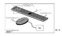
次に、図面を参照すると、図1A及び図1Bは、取り付け状態160及び分離状態170を有することによって特徴づけられる二状態式ウェアラブルデバイス150の一実施形態の2つの状態を示す。図1Aは、取り付け状態160にある二状態式ウェアラブルデバイス150の一実施形態を示す。取り付け状態160において、ディスプレイモジュール100(例えば、コンピュータ化された時計面)は、ウェアラブルバンド110(例えば、コンピュータ化された時計バンド)に取り付けられる。本出願のためにのみ、「状態」及び「ステージ」という用語は交換可能であり、ウェアラブルバンド110に取り付けられたときのディスプレイモジュール100の位置とウェアラブルバンド110から分離されたときの位置とを指す。
Referring now to the drawings, FIGS. 1A and 1B illustrate two states of one embodiment of a two-state wearable device 150 that is characterized by having an attached state 160 and a detached state 170. FIG. 1A illustrates one embodiment of a two-state wearable device 150 in the attached state 160. In the attached state 160, the display module 100 (eg, a computerized watch face) is attached to the wearable band 110 (eg, a computerized watch band). For the purposes of this application only, the terms “state” and “stage” are interchangeable and refer to the position of the
一実施形態において、取り付け状態160は、より能動的なセンサを有することが有用な使用期間に関連付けられる。例えば、取り付け状態160は、ウェアラブルデバイス150の日中の使用期間に関連付けられる。例えば、日中に、ディスプレイモジュール100は、ディスプレイモジュール100のディスプレイ245を通じて、時間の表示、天候の表示、電子メールの表示、SMS/テキストメッセージの表示、インスタントメッセージの表示、電話着信の表示、ビデオ着信の表示、カレンダイベントの表示、リマインダの表示、購入の表示、メール追跡の表示、フィットネス追跡の表示、健康追跡の表示、健康警告の表示、睡眠追跡(前夜の睡眠又は日中のうたた寝に関するもの)の表示、及び応答をタイピングし又は設定(例えば、図8に関して後に更に論じられる睡眠アラーム設定)を調節するためのグラフィカルユーザインターフェース(GUI)などの、ユーザが睡眠しているときにはアクセスされたり見られたりすることのないメッセージ及び情報をユーザに提供する。ディスプレイモジュール100は、マイク音声入力機能性などのユーザが応答可能な他の特徴も含んでよい。ディスプレイモジュール100は、(例えば、心拍数又は血圧を測定する)健康センサ、(例えば、歩行又は走行した歩数を計測する)フィットネスセンサ、又は(例えば、気温又は湿度を測定する)環境センサなどの様々なセンサも含んでよい。
In one embodiment, the attachment state 160 is associated with a period of use where having a more active sensor is useful. For example, the attachment state 160 is associated with a daytime usage period of the wearable device 150. For example, during the day, the
ウェアラブルデバイス150のウェアラブルバンド110は、いくつかの場合において、及び様々な実施形態において、ディスプレイモジュール100よりも低い電力を使用するように設計される。これは、いくつかの手法で達成される。例えば、ウェアラブルバンド110は、ディスプレイを全く有さなくてもよく、又は低電力のウェアラブルバンドディスプレイ190(又は少なくともディスプレイモジュール100よりも低電力なディスプレイ)を使用してもよく、又はディスプレイモジュール100のより強力なプロセッサ295に比べて単純なプロセッサ290を使用してもよい。代替的には、ウェアラブルバンド110は、ディスプレイモジュール100よりも低い電力を使用するように設計されることを必要とせず、その結果、フル機能のディスプレイ190(例えば、タッチスクリーンカラーディスプレイ190)及び/又はディスプレイモジュール100のプロセッサ295と同じ程度に又はそれよりも強力なプロセッサ290を含んでよい。ウェアラブルバンド110も、(例えば、心拍数又は血圧を測定する)健康センサ、(例えば、歩行又は走行した歩数を計測する)フィットネスセンサ、又は(例えば、気温又は湿度を測定する)環境センサなどのセンサを含んでよい。一実施形態において、ウェアラブルバンド110のセンサの出力及び他のデータは、次いで、ウェアラブルデバイス150が図1Aに示される取り付け状態160にあるときに、図1Bに示されるポート130を介してディスプレイモジュール100に供給される。代替的な実施形態において、ウェアラブルバンド110は、取り付け状態160にあるとき、又はウェアラブルバンド110がディスプレイモジュール100の無線範囲にあるならば分離状態170にあるときも、Bluetooth(登録商標)接続、高周波接続、インダクティブ(inductive)接続、Wi−Fi(登録商標)直接通信、又は近距離無線通信(near−field communication)などの無線接続を介してディスプレイモジュール100とデータを通信する。
The
一実施形態において、ウェアラブルデバイス150のウェアラブルバンド110は、取り付け状態160にあるとき、ディスプレイモジュール100からの充電も受ける。換言すれば、ディスプレイモジュール100のバッテリ255からの充電が、ウェアラブルバンドのバッテリ230を再充電するために使用される。代替的に、ウェアラブルバンド110が、ディスプレイモジュール100に充電を供給してもよい(例えば、ウェアラブルバンド110のバッテリ230からの充電が、ディスプレイモジュール100のバッテリ255を再充電するために使用されてよい)。(代替的な実施形態において、ウェアラブルバンド110は、壁に接続された充電器などの外部電源又は外部の接続可能バッテリから充電を受けてもよい。)
In one embodiment, the
図1Bは、分離状態170にある二状態式ウェアラブルデバイス150の一実施形態を示す。分離状態170において、ディスプレイモジュール100は、ウェアラブルバンド110から分離されている。これは、例えば、ウェアラブルバンド110が動作を継続してウェアラブルバンドのセンサ220を介してセンサ測定値を取得している間に、ディスプレイモジュール100を充電するために有用である。
FIG. 1B illustrates one embodiment of a two-state wearable device 150 in a detached state 170. In the separation state 170, the
一実施形態において、分離状態170は、例えば、ウェアラブルデバイス150を充電するために有用であるが、センサ測定値を取得するためにも依然として有用である期間に主に関連付けられる。ウェアラブルデバイス150全体を(例えば充電器200を使用して)電源120に結合することは、一般に、ケーブルや、無線充電ステーションへの近接を伴う。いくつかの機能(例えば、睡眠追跡)においてウェアラブルデバイス150の使用を継続しようと望むユーザは、ウェアラブルデバイスが充電のために電源120に接続されている間は、ウェアラブルデバイスを快適に又は確実に使用し続けることはできない。睡眠しているユーザは、無意識のうちに充電ケーブルに絡まってしまい、潜在的にユーザの生命を危険に晒すことがある。同様に、睡眠しているユーザが、近接ベースの無線充電ステーションから充電を受け続けるために、睡眠している間に彼/彼女の手を特定の位置に置いたままにすることは期待できない。ユーザが睡眠している間にデバイスを充電しようとするそのような試みによって生じる不快感は、ユーザの睡眠の品質及び持続を悪化させ、睡眠追跡デバイスを使用する目的を無にしてしまうことがある。代替的に、ウェアラブルバンド110は、ディスプレイモジュール100が異なるバンド(本明細書において説明されるスマートウェアラブルバンド110又は通常のバンドのいずれか)に取り付けられ、それによって装着されている間に充電されてよい。代替的に、ウェアラブルバンド110が充電されている間、ディスプレイモジュールは、締め紐(lanyard)、ベルトクリップ、ポーチなどによって装着されてよい。
In one embodiment, the isolation state 170 is primarily associated with a period of time that is useful, for example, for charging the wearable device 150, but still useful for obtaining sensor measurements. Coupling the entire wearable device 150 to the power source 120 (eg, using the charger 200) generally involves proximity to a cable or wireless charging station. Users who wish to continue using wearable device 150 for some functions (eg sleep tracking) comfortably or reliably use the wearable device while it is connected to
従って、分離状態170は、ウェアラブルバンド110が睡眠追跡機能などの特定の機能を維持することを可能にしつつディスプレイモジュール100を充電するために使用される。睡眠追跡機能は、ディスプレイモジュール100が分離されて充電されている間に、ウェアラブルバンド110のセンサ220及びウェアラブルバンド110のメモリ205(及び使用可能なときはウェアラブルバンド110のプロセッサ290)によって提供される。分離状態170中に、例えば、ウェアラブルバンド110は、ウェアラブルバンド110のセンサ220からセンサ測定値を(例えば、図2のウェアラブルバンド睡眠ソフトウェア215に従って)取得し、測定値をメモリ205に(例えば、図2のウェアラブルバンドデータベース210に)記憶する。センサ220からのセンサ測定値は、睡眠品質、睡眠持続時間、睡眠運動、睡眠パターン、睡眠中断、睡眠脈拍、睡眠血圧、睡眠呼吸、ユーザの入眠に関連する時間値、又はユーザの起床に関連する時間値に関連し得る。センサ220からのセンサ測定値は、血圧、脈拍、呼吸、又は図2に関して論じられる若しくは当技術分野において知られている、ウェアラブルデバイス150に追加されることが有利な任意の他の可能なセンサ測定値などの他の量も測定することもできる。
Accordingly, the separation state 170 is used to charge the
次いで、ウェアラブルバンド110及びディスプレイモジュール100は、朝に又はディスプレイモジュール100の充電が終了したときに、図1Aに描かれるようなウェアラブルデバイス15の取り付け状態160へと再接続される。ウェアラブルバンド110のセンサ220によって取得され、ウェアラブルバンド110によってメモリ205に記憶された任意のセンサ測定値(又はセンサ測定値の一部)は、次いで、(例えば、図2のディスプレイモジュールデータベース275における)記憶のために、及び/又は(例えば、図2のディスプレイモジュール睡眠ソフトウェア270による)解釈のために、ディスプレイモジュール100に転送される。また、ディスプレイモジュール100は次いで、(電源120からの充電によって)新たに再充電されたバッテリ255を使用して、ウェアラブルバンド110が再び(例えば次の夜に)すぐに使用できる状態になるまで、ウェアラブルバンド110のバッテリ230に充電を送る。代替的な実施形態において、ウェアラブルバンド110は、別の外部電源(例えば、充電器)から、又は別の外部の取り付け可能なバッテリから充電を受けてもよい。例えば、ウェアラブルバンド110は、ディスプレイモジュール100に加えて、ウェアラブルバンド110がユーザによって装着され続けている間に電力を供給し及び/又はバッテリ230(及び/又はバッテリ255)を充電するように構成された分離可能なバッテリを収容してもよい。ディスプレイモジュール100も同様に、ディスプレイモジュール100のバッテリ255又はウェアラブルバンド110のバッテリ230を充電するために使用される分離可能なバッテリを収容してもよい。
The
ウェアラブルバンド110は、時計、バイブレータ及び/又はスピーカも含む。これらは、指定時刻に作動するアラーム、又はユーザが「浅い」睡眠にあるとき(「深い」急速眼球運動「REM」睡眠にあるときではなく)にのみユーザを起床させる「スマート」アラームを通じてウェアラブルバンド110のユーザを起床させるために使用され得る。
一実施形態において、いずれの状態においても(代替的な実施形態においては、取り付け状態において)、ディスプレイモジュール100は、設定を調節するために使用される。これらの設定は、例えば、ウェアラブルバンド110によってどのセンサ220が使用されるべきかについて、センサ220のセンサ測定間の期間について、特定の時間にウェアラブルバンド110によって実行されるべきアラームの設定について、ユーザがどの睡眠ステージにあるかを考慮するために(例えば、ユーザがREM睡眠状態にあるときはユーザを起床させないようにする)センサ220のセンサ測定値を使用する、ウェアラブルバンド110によって実行されるべき「スマート」アラームの設定について、ウェアラブルバンド110によって実行されるべきアラームの音/ノイズの調節について、ウェアラブルバンド110によって実行されるべきアラームの振動の強さの調節について、ディスプレイモジュール100とウェアラブルバンド110との間での時計の同期について、及びウェアラブルバンド110の睡眠追跡機能性の他の設定について調節を行う。代替的に、設定は、ディスプレイモジュール100のセンサ250とディスプレイモジュール100によって実行されるべきアラームとに関連して同じ値を調節してもよい。代替的な実施形態において、これらの設定は、コンピュータ、モバイルデバイスなどのサードパーティのデバイスによって調節されてもよく、これらはディスプレイ100と、又は直接的にウェアラブルバンド110とペアにされる。
In one embodiment, in either state (in an alternative embodiment, in the attached state),
設定は、二状態式ウェアラブルデバイス150の状態(例えば、取り付け状態160又は分離状態170)に関わらず、ディスプレイモジュール100における睡眠グラフィカルユーザインターフェース(GUI)280を通じて調節される。次いで、次に二状態式ウェアラブルデバイス150が結合されて取り付け状態160になったときに、これらの設定は、(例えば、ポートを通じて、又は無線で)ウェアラブルバンド110に送信される。代替的に、睡眠GUI280からの設定は、分離状態170において、ディスプレイモジュール100からウェアラブルバンド110に無線で送信(例えば、定期的に又はユーザの入力によって始動する通信)されてもよい。同様に、二状態式ウェアラブルデバイス150は、ディスプレイモジュール100とウェアラブルバンド110との間で時計の同期を、二状態式ウェアラブルデバイス150が結合されて取り付け状態160になったときに(例えば、ポートを通じて、又は無線で)、又は分離状態170において無線によって(例えば、定期的に又はユーザの入力によって始動する同期)のいずれかにおいて、行ってもよい。
The settings are adjusted through the sleep graphical user interface (GUI) 280 on the
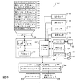
図2は、ウェアラブルバンド110及びディスプレイモジュール100含んだ二状態式ウェアラブルデバイスアーキテクチャの一実施形態を示す。一実施形態において、二状態式ウェアラブルデバイスアーキテクチャは、少なくともウェアラブルバンド110と、ディスプレイモジュール100と、電源120とを含む。
FIG. 2 illustrates one embodiment of a two-state wearable device architecture that includes a
図1A及び図1Bと共に部分的に説明されたように、ウェアラブルバンド110は、例えば、1つ又は複数のウェアラブルバンドセンサ220、バイブレータ225(「振動」)、プロセッサ290、電力貯蔵ユニット230(「バッテリ」)(例えば、再充電可能バッテリ又は交換可能バッテリ)、時計、メモリ205、及び通信/電力ポート/モジュール130(「ポート」)などの様々なコンポーネントを含む。ウェアラブルバンド110のメモリ205は、ウェアラブルバンドデータベース210と、ウェアラブルバンド睡眠ソフトウェア215又は様々な他の実施形態及びウェアラブルバンド110の用途に従って(フィットネスソフトウェアなどの)他のソフトウェアとを含む。図2に示されたウェアラブルバンドアーキテクチャは、限定ではなく例示と解釈されるべきであり、他の実施形態は、メモリに記憶される追加的な又は異なるコンポーネント又は要素を含んでよく、又は、メモリに記憶される示されたようなコンポーネント又は要素を欠いてもよい。
As described in part with FIGS. 1A and 1B, the
ウェアラブルバンド110の通信/電力ポート/モジュール130は、有線接続モジュール(例えば、USBポートモジュール、FireWireポートモジュール、Lightningポートモジュール、Thunderboltポートモジュール、カスタマイズされたオーディオジャックポートモジュール、磁気充電ケーブルポートモジュール、又は独自の(proprietary)ケーブルポートモジュール)、物理的接続モジュール(例えば、ウェアラブルバンド110からディスプレイモジュール100への金属リード線の直接の物理的な接触を介した通信可能又は電力供給接触)、又は無線の通信可能又は電力供給接続モジュールであってよい。無線の通信可能又は電力供給接続モジュールの機能は、分割又は組み合わされてよく、無線通信モジュール(例えば、Wi−Fi(登録商標)接続モジュール、3G/4G/LTEセルラー式接続モジュール、Bluetooth(登録商標)接続モジュール、低エネルギBluetooth(登録商標)接続モジュール、Bluetooth(登録商標)スマート接続モジュール、近距離無線通信モジュール、高周波通信モジュール)、及び無線電力モジュール(例えば、磁気誘導充電モジュール又は磁気共鳴充電モジュール)を含む。
The communication / power port /
一実施形態において、ウェアラブルバンド110の1つ又は複数のウェアラブルバンドセンサ220は、血圧、心拍数、体温(例えば、温度計)、血糖又はグルコース、加速度(例えば、加速度計)、インスリン、ビタミン値、呼吸数、心音(例えば、マイクロフォン)、呼吸音(例えば、マイクロフォン)、運動速度、歩行又は走行した歩数(例えば、歩数計)、皮膚の水分、汗の検知、汗の組成、神経発火(例えば、電磁センサ)又は類似の健康測定値を測定するためのセンサ220を含む。いくつかの実施形態において、追加的なセンサ220は、アレルゲン、空気清浄度、空気湿度、気温及び類似の環境測定値も測定し得る。
In one embodiment, one or more wearable band sensors 220 of
ディスプレイモジュール100は、ディスプレイ245と、1つ又は複数のディスプレイモジュールセンサ250と、電力貯蔵ユニット255(「バッテリ」)(例えば、再充電可能バッテリ又は交換可能バッテリ)と、メモリ260と、プロセッサ295と、通信/電力ポート/モジュール240と、充電ポート/モジュール285とを含む。
The
いくつかの実施形態において、ウェアラブルバンド通信/電力ポート/モジュール130は、ディスプレイモジュール通信/電力ポート/モジュール240と同じタイプの通信/電力ポート/モジュールでよく、又は、ウェアラブルバンド110とディスプレイモジュール100との間で、一方向又は双方向のいずれかに、電気通信及び/又は充電の転送を可能にするようなやり方でウェアラブルバンドポート/モジュール130がディスプレイモジュールポート/モジュール240に接続可能であるような、互換タイプのものであってもよい。代替的な実施形態において、ウェアラブルバンド110は、追加的なポート(不図示)を介して、ディスプレイモジュール100へ及び/又はそこから電力をやり取りする。ディスプレイモジュールのメモリ260は、ディスプレイモジュール基本ソフトウェア265と、ディスプレイモジュール睡眠ソフトウェア270と、ディスプレイモジュールデータベース275と、ディスプレイモジュール睡眠グラフィカルユーザインターフェース(GUI)280とを含む。ディスプレイモジュール110の通信/電力ポート/モジュール240は、ウェアラブルバンド110の通信/電力ポート/モジュール130に関して説明された通信/電力ポート/モジュールのうちの任意タイプのものを含む。通信/電力ポート/モジュール240は、通信/電力ポート/モジュール130と同じタイプの通信/電力ポート/モジュールである必要はない。図2に示されたディスプレイモジュール100アーキテクチャは、限定ではなく例示と解釈されるべきであり、他の実施形態は、メモリに記憶される追加的な又は異なるコンポーネント又は要素を含んでよく、又は、メモリ260に記憶される示されたようなコンポーネント又は要素を欠いてもよい。
In some embodiments, the wearable band communication / power port /
一実施形態において、充電ポート/モジュール285は、有線の電力受信接続モジュール(例えば、USBポートモジュール、FireWireポートモジュール、Lightningポートモジュール、Thunderboltポートモジュール、カスタマイズされたオーディオジャックポートモジュール、磁気力ケーブルポートモジュール、又は独自の電力ケーブルコネクタモジュール)、物理的充電モジュール(例えば、ウェアラブルバンド110から電源への金属リード線の直接の物理的な接触を介した充電)、又は無線充電モジュール(例えば、磁気誘導充電モジュール又は磁気共鳴充電モジュール)であってよい。
In one embodiment, the charging port /
一実施形態において、ディスプレイモジュール100の1つ又は複数のセンサは、血圧、心拍数、体温(例えば、温度計)、血糖又はグルコース、加速度(例えば、加速度計)、インスリン、ビタミン値、呼吸数、心音(例えば、マイクロフォン)、呼吸音(例えば、マイクロフォン)、運動速度、歩行又は走行した歩数(例えば、歩数計)、皮膚の水分、汗の検知、汗の組成、神経発火(例えば、電磁センサ)又は類似の健康測定値を測定するためのセンサを含む。いくつかの実施形態において、追加的なセンサは、アレルゲン、空気清浄度、空気湿度、気温及び類似の環境測定値も測定し得る。
In one embodiment, the one or more sensors of the
当業者は、本開示を精査することで、ディスプレイモジュール100は、ウェアラブルバンド110と同じ、又は異なるセンサを有し得ることを理解されよう。一実施形態において、ウェアラブルバンド110のセンサは、分離状態160にあるウェアラブルデバイス150のために適したタイプのもの(例えば、睡眠監視又はフィットネス追跡のためのもの)であり、その一方でディスプレイのセンサは、取り付け状態にあるウェアラブルデバイスのために適している。もちろん、これらは単なる例であり、各状態に対して意図される目的のために有利な任意のセンサが使用されてよい。当業者は、ウェアラブルバンド110のセンサは、バンド内に収まるサイズを有している(すなわち小型又は柔軟性のセンサ)ことを更に理解されよう。更には、取り付け状態にあるとき、任意のセンサがウェアラブルバンド110とディスプレイモジュール100との間で重複している(すなわち、両者が運動センサを有している)ならば、電力の節約のために重複したものの一方はオフにされてよい。代替的に、取り付け状態にあるとき、ウェアラブルバンド110のセンサの全て又は一部が電力の節約のためにオフにされてよい。更に別の実施形態において、取り付け状態にあるとき、ディスプレイモジュール100及びウェアラブルバンド110における異なるセンサが、それぞれの感知能力を増強及び向上させるために、又は一緒に動作して健康監視などを向上させるために使用されてよい。最後に、ディスプレイモジュール100は、取り付け状態にあるとき(又は、無線データ接続を介して接続されたとき)、ウェアラブルバンド110内に配置されたセンサの出力を直接的に制御し、及び読み取るように構成されてよい。逆に、ウェアラブルバンド110は、接続されたとき又は取り付け状態にあるとき、ディスプレイモジュール100内にあるセンサの出力を直接的に制御し、及び読み取ることができる。
Those skilled in the art will appreciate that the
電源120は、標準的壁ソケット(例えば、所定の電圧の電力を供給する)、発電機、バッテリ(例えば、ポータブルバッテリデバイス、又はカーバッテリ)などの任意のタイプの電源でよい。充電器200は、ケーブル(例えば、USBケーブル、FireWireケーブル、Lightningケーブル、Thunderboltケーブル、カスタマイズされたオーディオジャックケーブル、磁気充電ケーブル、又は独自のケーブル)、壁ソケット電流を特定の電圧及び/又はアンペア数及び/又は電流タイプ(例えば、交流又は直流)に適合するアダプタ、及び/又は無線充電ドック/クレイドル/マット/領域/ボリュームを含む。同様に、ディスプレイモジュール100は、バッテリ255を充電するために、追加的な解除可能に取り付け可能なバッテリを収容するように構成されてよい。そして、解除可能なバッテリは、それ自体を充電するために分離され得る。代替的な実施形態において、バッテリ255は、充電のためにディスプレイモジュール100から取り外されてよい。バッテリ255がディスプレイモジュール100から分離されている間に、第2のバッテリがモジュール100を電力供給された状態に保つ。このようにして、充電されたバッテリがディスプレイモジュール100の内外で交換される。
The
いくつかの実施形態において、ウェアラブルバンド110は、ウェアラブルバンドディスプレイ190を含み、これは低エネルギディスプレイ(例えば、発光ダイオードディスプレイ)である。図2には図示されていないが、低エネルギディスプレイ190の一実施形態は、図1Bのウェアラブルバンド110の一実施形態に示されている(「ALARM SET:7:30AM」と表示している)。
In some embodiments,
二状態式ウェアラブルデバイス150の動作の一実施形態は、例えば、一日の間に二状態式ウェアラブルデバイス150を使用し、取り付け状態160にあるウェアラブルデバイス150のディスプレイモジュール100のセンサ250から及び/又はウェアラブルバンド110のセンサ220からの様々な異なるセンサ読み取り値を取得するユーザである。一日の終わりに、二状態式ウェアラブルデバイス150を充電することをユーザが決めると、ユーザは自身が起床したいと望む時刻を睡眠GUI280に入力する(次いで、これはウェアラブルバンド110に転送される)が、二状態式ウェアラブルデバイス150の全体を取り外す代わりに、ユーザはディスプレイモジュール100だけを取り外し、ウェアラブルバンド110は着けたままにする。これによってウェアラブルデバイス150の「状態」が取り付け状態160から分離状態170に変化する。次いで、ディスプレイモジュール100は、夜間全体を通して、その電力貯蔵ユニット255(例えば、再充電可能バッテリ)を電源120を使用して充電する一方、(それ自身の電力貯蔵ユニット230、センサ220、時計235、アラーム、及びバイブレータ225を有する)ウェアラブルバンド110は電力を供給されて動作し続け、ウェアラブルバンドセンサ220を使用してユーザにセンサ読み取り値を提供する(例えば、ユーザの睡眠行為を測定する)。朝になると、ウェアラブルバンド110は、睡眠GUI280からの睡眠設定に従って振動してユーザを起床させる。ユーザは、充電されたディスプレイモジュール100をウェアラブルバンド110に再び取り付けてウェアラブルデバイス150を分離状態170から取り付け状態160にする。次いで、ウェアラブルバンド110は、夜の間にセンサ220から記録したセンサデータを、ディスプレイモジュールデータベース275への追加のためにディスプレイモジュール100に送信する。ディスプレイモジュール100は、次に(又は同時に、又はその前に)、そのバッテリ255から送られた電気エネルギ/充電をウェアラブルバンドのバッテリ230を再充電するために供給し、ウェアラブルデバイス150が次の夜に分離状態170に戻ったときにウェアラブルバンド110が再び機能できるようにする。
One embodiment of the operation of the two-state wearable device 150 uses, for example, the two-state wearable device 150 during the day, and / or from the
一実施形態において、二状態式ウェアラブルデバイス150は、フィットネスの目的にも適合する。例えば、ユーザは、衝撃又は水によるダメージによって損傷することを避けるためにディスプレイモジュール100をロッカーに置いたままにしてウェアラブルバンド110を使用することができる。この目的で、たとえディスプレイモジュール100が耐水性でなかったとしても、ウェアラブルバンド110は耐水性を有するように作られる。しかしながら、いくつかの実施形態において、ディスプレイモジュール100も耐水性であってよい。
In one embodiment, the two-state wearable device 150 is also suitable for fitness purposes. For example, the user can use the
二状態式ウェアラブルデバイス150は、1つのディスプレイモジュール100につき複数のウェアラブルバンド110を含んでもよい。例えば、種々のウェアラブルバンド110が異なる目的(例えば、個別の睡眠ウェアラブルバンド110及び個別のフィットネスウェアラブルバンド110)及びこれらの目的を達成するための異なる統合センサを有してよい。いくつかの実施形態において、ウェアラブルバンド110は、イベントにおいて配布又は販売されてよく、例えば、そのイベントに関連した特別なイベントソフトウェア(例えば、音楽関連イベント、独立祭などの文化的大会、政治イベントのための特定の色を有した統合されたLEDライトを有するウェアラブルバンド)を含んでよい。ウェアラブルバンド110は、特定のユーザのファッション、快適性及びフィットネスのニーズに適した又は特定のイベントに合った様々なスタイル及び色で提供されてもよい。更には、ウェアラブルバンド110及び/又はディスプレイモジュール100は、プラスチック、シリコーン又は金属など様々な材料で提供されてよい。いくつかの実施形態において、ユーザは、ウェアラブルバンド110及び/又はディスプレイモジュール100をサードパーティのデバイス(例えば、ユーザのコンピュータ、ユーザのモバイルデバイス、医師のコンピュータ、医師のモバイルデバイス、又は医師のウェアラブルデバイス150)に接続して、データをサードパーティのデバイスに転送し(例えば、ウェアラブルバンドデータベース210及び/又はディスプレイモジュールデータベース275及び/又は睡眠GUIの睡眠設定)、サードパーティのデバイスからデータを受信し、又はサードパーティのデバイスとデータを同期することができる。複数のウェアラブルバンド110を有することで、充電が低くなり始めたならば、ユーザは1つのバンドを完全に充電されたウェアラブルバンドに交換することができる。
The two-state wearable device 150 may include a plurality of
いくつかの実施形態において、ディスプレイモジュール100は、多様な性能を有する複雑なコンピュータデバイスである。他の実施形態において、ディスプレイモジュール100は、単純なユーザインターフェース(例えば、時間だけを表示する)を備えてよく、それ自体で単独のデバイスとしてではなくウェアラブルバンド110のためのバッテリパックとして機能してもよい。そのような実施形態においては、代替的に、基本ソフトウェア265、睡眠ソフトウェア270、データベース275、及び睡眠GUIは、ディスプレイモジュールメモリ260に記憶されてプロセッサ295によって実行される代わりに、ウェアラブルバンドメモリ205に記憶され、及び/又はウェアラブルバンドプロセッサ290によって実行され得る。
In some embodiments, the
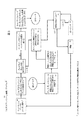
図3は、ウェアラブルバンド110の一実施形態によって実行される睡眠ソフトウェアの動作の一実施形態を示すフロー図である。睡眠ソフトウェアは、ウェアラブルバンド110の睡眠追跡機能性、及びウェアラブルバンド110とディスプレイモジュール100との間の接続に関する様々な機能を制御する。
FIG. 3 is a flow diagram illustrating one embodiment of sleep software operations performed by one embodiment of
一実施形態において、睡眠ソフトウェアの動作は、ステップ300において、ウェアラブルバンド110がルーチン動作を行うことから始まる。ウェアラブルバンド110の場合、ルーチン動作とは、ルーチン睡眠追跡動作を意味し、すなわち、ウェアラブルバンド110の1つ又は複数センサ220からセンサ測定値入力(例えば、運動追跡、心拍数、呼吸又は図2のウェアラブルバンド110の一実施形態に関して説明された他の可能なセンサ入力のうちの任意のもの)を受信することを意味する。ルーチン動作は、データ分析及び報告(例えば、センサ入力に基づいて睡眠品質又は睡眠ステージを計算する)も含む。次いで、ステップ305において、ウェアラブルバンド110は、センサ測定値入力からの及び/又はデータ分析/報告からの未加工のデータをウェアラブルバンド110のメモリ205に(例えば、ウェアラブルバンドデータベース210内に)記憶する。
In one embodiment, the operation of the sleep software begins with the
一実施形態において、ウェアラブルバンド110は、次いで、ステップ310において、ディスプレイモジュール100がウェアラブルバンド110に接続されているかを判定するために(例えば、二状態式ウェアラブルデバイス150が図1Bの分離状態170ではなく図1Aに示された取り付け状態160にあるかを確かめるために)、ポーリングを行う。ウェアラブルバンド110がディスプレイモジュール100に接続されているなら、次いでウェアラブルバンド110は、ステップ315において、ディスプレイモジュールの電力貯蔵ユニット255(例えば、再充電可能バッテリ又は交換可能バッテリ)からウェアラブルバンドの電力貯蔵ユニット230(例えば、再充電可能バッテリ)への充電を受ける。代替的に、ウェアラブルバンド110は、ウェアラブルバンドの電力貯蔵ユニット255(例えば、再充電可能バッテリ又は交換可能バッテリ)からディスプレイモジュールの電力貯蔵ユニット230(例えば、再充電可能バッテリ)へ充電を送ってもよい。次いで、ステップ320において、ウェアラブルバンド110は、ウェアラブルバンドデータベース210の少なくともサブセット(又はいくつかの他のフォーマットのセンサ測定値及び/又はデータ分析/報告データ)をディスプレイモジュール100に送信し、ステップ330において、ディスプレイモジュール100は、ウェアラブルバンドデータベース210を受信して、ディスプレイモジュールの基本ソフトウェア265を使用して処理する(図5に関連して更に詳細に説明される)。代替的な実施形態において、ディスプレイモジュール100が取り付けられているかをチェックする代わりに、ディスプレイモジュール110は、取り付け通知をウェアラブルバンド110に送ることによって、ウェアラブルバンド110に取り付けを通知してもよい。例えば、ディスプレイモジュールは、ウェアラブルバンド110の内部変数にアクセスしてこれを変更し、ウェアラブルバンド110に接続を通知する。
In one embodiment, the
ステップ310においてディスプレイモジュール100が接続されているかをウェアラブルバンド110がチェックした際に、もしもディスプレイモジュール100が接続されていることが見つからなかったなら(例えば、二状態式ウェアラブルデバイス150が、図1Aの取り付け状態160ではなく図1Bに示された分離状態170にあるならば)、ステップ325において、ウェアラブルバンド110は、ディスプレイモジュールの睡眠設定GUI280から(又はサードパーティのデバイスから)事前に取得した睡眠設定をチェックし、これらの睡眠設定をウェアラブルバンド110の時計と突き合わせて、ウェアラブルバンド110によってアクションが開始されるべきであることをこれらの設定のうちのいずれかが示すかをチェックする。これらの睡眠設定は、ステップ335において、ディスプレイモジュールの睡眠設定GUI280を使用して入力され(図9に関連して更に詳細に説明される)、ステップ340において、ディスプレイモジュールの睡眠ソフトウェア270から送信されてウェアラブルデバイス150において受信され、ステップ345において、ウェアラブルバンド110のウェアラブルバンド睡眠ソフトウェア215にセーブされる。ステップ350においてウェアラブルバンド110によってアクションが開始されるべきであるかを判定するためにウェアラブルバンド110が時間及び睡眠設定をチェックした際に、もしも合致する睡眠設定がなかったなら、ステップ355において、ウェアラブルバンド110は定期的にポーリングを行い続け、ウェアラブルバンド110によってアクションが開始されるべきであることを示す、合致する睡眠設定をチェックする。いくつかの実施形態において、ウェアラブルバンド110は、ステップ300のウェアラブルバンドのルーチン動作に戻ってもよく、又はステップ310のディスプレイモジュール100が接続されているかを確かめるチェックに戻ってもよい。
When the
もしもステップ350においてウェアラブルバンド110によってアクションが開始されるべきであることを示す、合致する睡眠設定がウェアラブルバンド110にあるなら、次いで、ステップ360において、ウェアラブルバンド110はユーザにアラートを発する。ステップ360におけるこのアラートはウェアラブルバンド110のバイブレータからの振動の形態をとっているが、又はウェアラブルバンド110のスピーカから再生されるオーディオクリップの形態、ウェアラブルバンド110のディスプレイ190に表示されるテキスト通知の形態、ウェアラブルバンド110のディスプレイ190に表示されるグラフィカルな通知の形態、ウェアラブルバンド110のディスプレイ190及び/若しくはスピーカを使用して再生されるビデオ通知の形態、又はこれらのいくつかの組み合わせの形態をとってもよい。合致する睡眠設定は、例えば、アラーム又は「スマート」アラームであってよい。
If there is a matching sleep setting in
図3のフロー図は、ある実施形態によって行われる動作の特定の順序を図示するが、そのような順序は一実施形態にすぎないことを理解されたい(例えば、代替的な実施形態は、異なる順序で動作を行ってよく、いくつかの動作を組合わせてよく、いくつかの動作を並行して行ってよい)。 Although the flow diagram of FIG. 3 illustrates a particular order of operations performed by an embodiment, it should be understood that such an order is only one embodiment (e.g., alternative embodiments are different). The actions may be performed in order, several actions may be combined, and several actions may be performed in parallel).
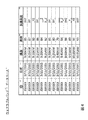
図4は、ウェアラブルバンド110の一実施形態のメモリ205に記憶されるウェアラブルバンドデータベース210の一実施形態を示す。ウェアラブルバンドデータベース210の一実施形態は、ウェアラブルバンドセンサ220からのセンサ測定値に関する複数の列(本明細書において説明される列は、データベース210に記憶されるデータのカテゴリの単なる例である)を含む。いくつかの列は、ユーザ識別情報(ID)400、測定日410、測定時刻420及び記された日時に対応する様々なセンサ測定値に対応する。センサ測定値は、例えば、脈拍センサ430からの測定値及び加速度計440からの測定値を含む。
FIG. 4 illustrates one embodiment of
ウェアラブルバンドデータベース210のこの実施形態において、全てのエントリは、ユーザID「JSXXXX」(例えば、「ID」列400)を有するユーザに属する。他の場合には、全てのエントリが同じユーザに帰属する必要はなく、例えば、ウェアラブルデバイス150は、ウェアラブルデバイス150を使用する複数のユーザ(例えば、家族の異なるメンバーが、同じウェアラブルデバイス150を使用してスイッチオフにし、異なるユーザに対応するデータは「ID」列400に異なって記される)に対応する複数のユーザIDを含んでよい。
In this embodiment of
例えば、図4に図示された全ての測定値は、2015年3月11日(3/11/2015)(例えば、「日付」列410)に取得されている。いくつかの場合には、データベース210は、複数日からのデータを記憶する。いくつかの場合には、データベース210からのデータがディスプレイモジュール100に転送されたとき、データベース210はクリアされる。図示されるように、データベース210内の測定値は、3月11日のAM9:00からAM10:05の間に(例えば、「時刻」列420)5分おきに取得されている。これは、睡眠GUI280などの設定インターフェース又は別のインターフェースを使用して調節される。脈拍測定値は、(AM9:40における)最低値79から(AM10:05における)最高値93の間の範囲にある(例えば、「脈拍」列430)。加速度計は、測定された時間帯全体にわたって運動を追跡し、X方向及び/又はY方向及び/又はZ方向の運動が検知されたときに「X」、「Y」及び「Z」の表示で示している(例えば、「加速度計」列440)。いくつかの場合には、加速度計は、運動の距離又は程度などのより詳細な運動データを測定してもよい。
For example, all measurements shown in FIG. 4 have been acquired on March 11, 2015 (3/11/2015) (eg, “Date” column 410). In some cases,
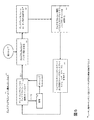
図5は、ディスプレイモジュール100の一実施形態によって実行されるディスプレイモジュール基本ソフトウェア265の動作の一実施形態を示すフロー図である。基本ソフトウェア265は、二状態式ウェアラブルデバイス150、特にはディスプレイモジュール100の、及びディスプレイモジュール100とウェアラブルバンド110との間の接続の、様々な動作を制御する。
FIG. 5 is a flow diagram illustrating one embodiment of the operation of the display module
先ず、基本ソフトウェア265は、ステップ500において、ディスプレイモジュール100がウェアラブルバンド110に接続されているかを確認するチェックを行う。もしもウェアラブルバンド110に接続されていないなら、次いで、ステップ505において、もしも電源120に接続されているなら、ディスプレイモジュール100はそのバッテリ255を充電し、ステップ510において、ウェアラブルバンド110がディスプレイモジュール100に接続されたかを確かめるために定期的にポーリングを行う。ディスプレイモジュール100がウェアラブルバンド110に接続されていたなら(例えば、ステップ515のこの接続におけるウェアラブルバンド110の役割に関する詳細は図3に示されている)、ディスプレイモジュール100は、ディスプレイモジュール100のバッテリ255からウェアラブルバンド110のバッテリ230に電力を送る(ステップ520)。代替的に、ディスプレイモジュールのバッテリ255は、いくつかの実施形態においてウェアラブルバンド110のバッテリ230から、又は代替的な実施形態において外部の接続されたバッテリから電力を受信してもよい。
First, in
次いで、ステップ525において、ディスプレイモジュール100はルーチン動作を実行する。例えば、これらのルーチン動作は、ディスプレイモジュール100の1つ又は複数のセンサ250からセンサ測定値入力(例えば、運動追跡、心拍数、呼吸又は図2のディスプレイモジュール100に関して説明された他の可能なセンサ入力のうちの任意のもの)を受信することを含む。ルーチン動作は、データ分析及び報告(例えば、センサ入力に基づいて燃焼カロリを計算する)も含む。次いで、ステップ530において、ディスプレイモジュール100は、ウェアラブルバンド睡眠ソフトウェア215からウェアラブルバンドデータベース210を受信する。次いで、ステップ535において、ディスプレイモジュール100は、ウェアラブルバンドデータベース210、並びに/又はウェアラブルバンドデータベース210からの(例えば、ウェアラブルバンドセンサ220からのセンサ測定値)及び/若しくはディスプレイモジュール自身のセンサ250からの未加工のセンサ測定値データ及び/若しくは未加工のデータ分析/報告データを、ディスプレイモジュールのメモリ260に(例えば、ディスプレイモジュールデータベース275に)記憶する。次いで、ディスプレイモジュール100は、ステップ500のディスプレイモジュール100が未だにウェアラブルバンド110に接続されているかのチェックに戻る。
Next, in
図5のフロー図は、ある実施形態によって行われる動作の特定の順序を図示するが、そのような順序は一実施形態にすぎないことを理解されたい(例えば、代替的な実施形態は、異なる順序で動作を行ってよく、いくつかの動作を組合わせてよく、いくつかの動作を並行して行ってよい)。 Although the flow diagram of FIG. 5 illustrates a particular order of operations performed by an embodiment, it should be understood that such an order is only one embodiment (e.g., alternative embodiments are different). The actions may be performed in order, several actions may be combined, and several actions may be performed in parallel).
図6は、本明細書において説明される様々な特徴及び処理を実施するために利用されるコンピューティングデバイスアーキテクチャの一実施形態を示す。例えば、コンピューティングデバイスアーキテクチャ600は、ウェアラブルバンド110及び/又はディスプレイモジュール100において実現され得る。図6に示されるアーキテクチャ600は、メモリインターフェース602と、プロセッサ604と、周辺機器インターフェース606とを含む。メモリインターフェース602、プロセッサ604及び周辺機器インターフェース606は、個別のコンポーネントであってよく、又は1つ又は複数の集積回路の一部として統合されてもよい。様々なコンポーネントは、1つ又は複数の通信バス又は信号線によって結合され得る。
FIG. 6 illustrates one embodiment of a computing device architecture that can be utilized to implement the various features and processes described herein. For example,
図6に示されるプロセッサ604は、データプロセッサ、イメージプロセッサ、中央処理ユニット、又は任意の様々なマルチコア処理デバイスを含むものと意図される。任意の様々なセンサ、外部デバイス及び外部サブシステムが、例示的なモバイルデバイスのアーキテクチャ600内の任意の数の機能性を促進するために周辺機器インターフェース606に結合され得る。例えば、運動センサ610、光センサ612及び近接センサ614が、モバイルデバイスの向き、照明及び近接機能を促進するために周辺機器インターフェース606に結合され得る。例えば、光センサ612は、タッチサーフェス646の明るさの調節を促進するために利用される。例として加速度計又はジャイロスコープなどがある運動センサ610は、モバイルデバイスの動き及び向きを検知するために利用される。それにより、表示オブジェクト又は媒体は、検知された向きに従って(例えば、ポートレート表示又はランドスケープ表示)提示される。
The
温度センサ、生体測定(biometric)センサ又は対応する機能性を促進する他の感知デバイスなどの他のセンサが、周辺機器インターフェース606に結合されてもよい。位置プロセッサ615(例えば、全地球測位トランシーバ)は、地理位置データの生成を可能にし、それによって地理測位を促進するために周辺機器インターフェース606に結合され得る。集積回路チップなどの電子磁気計616は、正確な磁北の方向に関連するデータを提供し、それによってモバイルデバイスがコンパス又は方位についての機能性を得るように、周辺機器インターフェース606に接続され得る。電荷結合素子(CCD:charged coupled device)又は相補型金属酸化膜半導体(CMOS:complementary metal−oxide semiconductor)光学的センサなどのカメラサブシステム620及び光学的センサ622は、写真又はビデオクリップの記録などのカメラ機能を促進し得る。
Other sensors may be coupled to the
一実施形態において、通信機能性は、1つ又は複数の通信サブシステム624を通じて促進され得、これらは1つ又は複数の無線通信サブシステムを含む。無線通信サブシステム624は、802.x又はBluetooth(登録商標)トランシーバ、及び赤外線などの光学的トランシーバを含み得る。有線通信システムは、ネットワークアクセスデバイス、パーソナルコンピュータ、プリンタ、ディスプレイ、又はデータを受信又は送信可能な他の処理デバイスなどの他のコンピューティングデバイスへの有線結合を確立するために使用可能なユニバーサルシリアスバス(USB:Universal Serial Bus)ポート又はいくつかの他の有線ポート接続などのポートデバイスを含み得る。通信サブシステム624の特定の設計及び実施態様は、デバイスが動作することを意図される通信ネットワーク又は媒体に依存する。例えば、デバイスは、移動体通信用グローバルシステム(GSM(登録商標):global system for mobile communications)ネットワーク、GPRSネットワーク、拡張データGSM(登録商標)環境(EDGE:enhanced data GSM(登録商標) environment)ネットワーク、802.x通信ネットワーク、符号分割多重アクセス(CDMA:code division multiple access)ネットワーク、又はBluetooth(登録商標)ネットワークにおいて動作するように設計された無線通信サブシステムを含む。通信サブシステム624は、デバイスが他の無線デバイスのベースステーションとして構成されるように、ホスティングプロトコルを含んでよい。通信サブシステムは、デバイスがTCP/IP、HTTP、又はUDPなどの1つ又は複数のプロトコルを使用してホストデバイスと同期することも可能にし得る。
In one embodiment, communication functionality may be facilitated through one or
音響サブシステム626は、音声を使用可能な機能を促進するために、スピーカ628及び1つ又は複数のマイクロフォン630に結合され得る。これらの機能は、音声認識、音声再現、又はデジタル録音を含む。これに併せて音響サブシステム626は、従来の電話機能を含んでもよい。
The
I/Oサブシステム640は、タッチコントローラ642及び/又は他の入力コントローラ644を含む。タッチコントローラ642は、タッチサーフェス646に結合され得る。タッチサーフェス646及びタッチコントローラ642は、静電性、抵抗性、赤外線又は弾性表面波技術を含むがこれらに限定されない多くのタッチ感知技術のうちの任意のものを使用して、接触及び動き又はその中断を検知する。タッチサーフェス646との1つ又は複数の接触のポイントを判定するための他の近接センサアレイ又は要素も、同様に利用されてよい。1つの実施態様において、タッチサーフェス646は、ユーザによって入力/出力デバイスとして使用され得る仮想又はソフトボタン及び仮想キーボードを表示できる。
The I /
一実施形態において、1つ又は複数のボタン、ロッカースイッチ、サムホイール、赤外線ポート、USBポート及び/又はスタイラスなどのポインタデバイスなどの、他の入力コントローラ644が他の入力/制御デバイス648に結合され得る。1つ又は複数のボタン(不図示)は、スピーカ628及び/又はマイクロフォン630のボリューム制御のための上/下ボタンを含み得る。いくつかの実施態様において、デバイス600は、音響及び/又は映像再生若しくは記録デバイスの機能性を含み得、他のデバイスとのコード接続(tethering)のためのピンコネクタを含む。
In one embodiment,
メモリインターフェース602は、メモリ650に結合され得る。メモリ650は、高速ランダムアクセスメモリ、又は磁気ディスク記憶デバイス、光学的記憶デバイス若しくはフラッシュメモリなどの不揮発性メモリを含み得る。メモリ650は、Darwin、RTXC、LINUX、UNIX(登録商標)、OS X、ANDROID(登録商標)、WINDOWS(登録商標)、又はVxWorksなどの埋め込み式オペレーティングシステムなどのオペレーティングシステム652を記憶可能である。オペレーティングシステム652は、基本システムサービスを取り扱うための、及びハードウェア依存のタスクを実施するためのインストラクションを含む。いくつかの実施態様において、オペレーティングシステム652は、カーネルを含み得る。
メモリ650は、他のモバイルコンピューティングデバイス又はサーバとの通信を促進する通信インストラクション654も記憶する。通信インストラクション654は、GPS/ナビゲーションインストラクション668によって取得される地理位置に基づいたデバイスによる使用のための動作モード又は通信媒体を選択するためにも使用され得る。メモリ650は、インターフェースの生成などのグラフィカルユーザインターフェース処理を促進するグラフィカルユーザインターフェースインストラクション656と、センサに関連した処理及び機能を促進するセンサ処理インストラクション658と、電話に関連したプロセス及び機能を促進する電話インストラクション660と、電子メッセージに関連したプロセス及び機能を促進する電子メッセージインストラクション662と、ウェブ閲覧に関連したプロセス及び機能を促進するウェブ閲覧インストラクション664と、媒体処理に関連したプロセス及び機能を促進する媒体処理インストラクション666と、GPS及びナビゲーションに関連するプロセスを促進するGPS/ナビゲーションインストラクション668と、カメラに関連したプロセス及び機能を促進するカメラインストラクション670と、モバイルコンピューティングデバイス上で又はそれと共に動作する任意の他のアプリケーションのためのインストラクション672とを含む。メモリ650は、ナビゲーション、ソーシャルネットワーク、位置ベースのサービス又は地図表示などに関連したアプリケーションなどの他のプロセス、特徴及びアプリケーションを促進するための他のソフトウェアインストラクションも記憶する。
上記の特定されたインストラクション及びアプリケーションの各々は、上述された1つ又は複数の機能を行うためのインストラクションのセットに対応し得る。これらのインストラクションは、個別のソフトウェアプログラム、プロシージャ又はモジュールとして実現される必要はない。メモリ650は、追加的なインストラクションを含んでよく、又は含まれるインストラクションがこれより少なくてもよい。更には、モバイルデバイスの様々な機能は、1つ又は複数の信号処理及び/又は特定用途向け集積回路などのハードウェア又はソフトウェアにおいて実現されてよい。
Each of the above identified instructions and applications may correspond to a set of instructions for performing one or more of the functions described above. These instructions need not be implemented as separate software programs, procedures or modules.
ある特徴は、データサーバなどのバックエンドコンポーネント、アプリケーションサーバ若しくはインターネットサーバなどのミドルウェアコンポーネント、又はグラフィカルユーザインターフェース若しくはインターネットブラウザを有するクライアントコンピュータなどのフロントエンドコンポーネント、又は前述のものの任意の組み合わせを含むコンピュータシステムにおいて実現されてよい。システムのコンポーネントは、通信ネットワークなどのデジタルデータ通信の任意の形態又は媒体によって接続可能である。通信ネットワークのいくつかの例としては、LAN、WAN、並びにインターネットを形成するコンピュータ及びネットワークなどが含まれる。コンピュータシステムは、クライアントとサーバとを含み得る。クライアント及びサーバは、概して、互いから遠く離れており、典型的にはネットワークを通じて相互作用する。クライアント及びサーバの関係は、それぞれのコンピュータ上で動作し、互いにクライアント−サーバ関係を有するコンピュータプログラムによって生じる。 Certain features include a back-end component such as a data server, a middleware component such as an application server or Internet server, or a front-end component such as a client computer having a graphical user interface or Internet browser, or any combination of the foregoing. May be implemented. The components of the system can be connected by any form or medium of digital data communication such as a communication network. Some examples of communication networks include LANs, WANs, and computers and networks that form the Internet. The computer system can include clients and servers. A client and server are generally remote from each other and typically interact through a network. The client and server relationship is caused by computer programs that run on each computer and have a client-server relationship with each other.
開示される実施形態の1つ又は複数の特徴又はステップは、呼び出しアプリケーションと、オペレーティングシステム、ライブラリルーチン、及びサービス若しくはデータの提供又は動作若しくは計算の実施を行う機能などの他のソフトウェアコードとの間でやり取りされる1つ又は複数のパラメータを規定し得るAPIを使用して実現される。APIは、API仕様書において定義された呼び出し規約に基づくパラメータリスト又は他の構造を通じて1つ又は複数のパラメータを送信又は受信するプログラムコードにおける1つ又は複数の呼び出しとして実現され得る。パラメータは、定数、キー、データ構造、オブジェクト、オブジェクトクラス、変数、データタイプ、ポインタ、アレイ、リスト、又は別の呼び出しであってよい。API呼び出し及びパラメータは、任意のプログラム言語において実現され得る。プログラム言語は、APIをサポートする機能にアクセスするためにプログラマが用いる用語集及び呼び出し規約を定義し得る。いくつかの実施態様において、API呼び出しは、入力性能、出力性能、処理性能、電力性能及び通信性能などの、アプリケーションを実行するデバイスの性能をアプリケーションに報告し得る。 One or more features or steps of the disclosed embodiments are between the calling application and other software code, such as operating system, library routines, and other software code such as providing services or data or performing operations or calculations. It is implemented using an API that can define one or more parameters to be exchanged. An API may be implemented as one or more calls in program code that send or receive one or more parameters through a parameter list or other structure based on calling conventions defined in the API specification. The parameter may be a constant, key, data structure, object, object class, variable, data type, pointer, array, list, or another call. API calls and parameters can be implemented in any programming language. The programming language may define a glossary and calling convention that programmers use to access functions that support the API. In some implementations, the API call may report to the application the performance of the device executing the application, such as input performance, output performance, processing performance, power performance and communication performance.
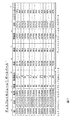
図7は、ディスプレイモジュール100の一実施形態のメモリ260に記憶されるディスプレイモジュールデータベース275の一実施形態を示す。これは、ウェアラブルバンド110のセンサ220及びディスプレイモジュール100のセンサ250からのデータを組合わせて記憶する。一実施形態において、ディスプレイモジュールデータベース275は、複数の列を含み、各列は、ユーザ識別情報(ID)705、測定日710、測定時刻715及び記された日時に対応する様々なセンサ測定値に対応する。センサ測定値は、例えば、脈拍センサ720、加速度計センサ725、血圧センサ730、体温センサ735及び呼吸数センサ740からの測定値を含む。ディスプレイモジュールデータベース275は、ウェアラブルバンド110及びディスプレイモジュール100の1つ又は両方に関する他のデータ、すなわち、全地球測位システム又は「GPS」位置モジュール740からの測定の時刻/日付における読み取り値、バッテリ255及び/又はバッテリ230に残るバッテリ電力のパーセンテージを検知するバッテリパーセンテージ検知器モジュール750からの読み取り値を含む。
FIG. 7 illustrates one embodiment of a
図7のディスプレイモジュールデータベース275の実施形態の最初の5つの列は、図4のウェアラブルバンドデータベース210の実施形態からのものと同じである。
The first five columns of the embodiment of the
一実施形態において、図7のディスプレイモジュールデータベース275の全てのエントリは、ユーザID「JSXXXX」(例えば、「ID」列705)を有するユーザに属する。他の場合には、全てのエントリが同じユーザに帰属する必要はなく、例えば、ウェアラブルデバイス150は、ウェアラブルデバイス150を使用する複数のユーザ(例えば、家族の異なるメンバーが、同じウェアラブルデバイス150を使用してスイッチオフにし、異なるユーザに対応するデータは「ID」列705に異なって記される)に対応する複数のユーザIDを含んでよい。
In one embodiment, all entries in the
全ての測定値は、2015年3月11日(3/11/2015)(例えば、「日付」列710)に取得されている。いくつかの場合には、データベース275は、複数日からのデータを記憶する。いくつかの場合には、データベース275からのデータがディスプレイモジュール100に転送されたとき、データベース275はクリアされる。
All measurements have been taken on March 11, 2015 (3/11/2015) (eg, “Date” column 710). In some cases,
データベース275内の測定値は、3月11日のAM9:00からAM10:05の間に(例えば、「時刻」列715)5分おきに取得されている。これは、睡眠GUI280などの設定インターフェース又は別のインターフェースを使用して調節される。
Measurements in the
脈拍測定値は、(AM9:40における)最低値79から(AM10:05における)最高値93の間の範囲にある(例えば、「脈拍」列720)。一実施形態において、加速度計は、測定された時間帯全体にわたって運動を追跡し、X方向及び/又はY方向及び/又はZ方向の運動が検知されたときに「X」、「Y」及び「Z」の表示で示している(例えば、「加速度計」列725)。いくつかの場合には、加速度計は、運動の距離又は程度などのより詳細な運動データを測定してもよい。 Pulse measurements are in the range between the lowest value 79 (at AM 9:40) and the highest value 93 (at AM 10:05) (eg, “pulse” column 720). In one embodiment, the accelerometer tracks motion throughout the measured time period and “X”, “Y”, and “Y” when motion in the X and / or Y and / or Z directions is detected. Z ”(for example,“ accelerometer ”column 725). In some cases, the accelerometer may measure more detailed motion data such as distance or degree of motion.
ディスプレイモジュールデータベース275は、ディスプレイモジュール100の血圧センサからの血圧測定値も追加する(例えば、「血圧」列730)。ディスプレイモジュールデータベース275は、ディスプレイモジュール100の温度計からの体温測定値(98.4から98.6の範囲)も追加する(例えば、「体温」列735)。ディスプレイモジュールデータベース275は、ディスプレイモジュール100の呼吸数センサからの呼吸数測定値(11/minから14/minの範囲)も追加する(例えば、「呼吸数」列740)。ディスプレイモジュールデータベース275は、ディスプレイモジュール100のGPSモジュールからの全地球測位システム又は「GPS」位置座標も追加する(例えば、「GPS」列745)。ディスプレイモジュールデータベース275は、ディスプレイモジュールのバッテリ255及び/又はウェアラブルバンドのバッテリ230における残りのバッテリ電力のパーセンテージに関するバッテリパーセンテージ測定値も追加する(例えば、「バッテリパーセンテージ」列750)。
The
図8は、ディスプレイモジュール100によって実行される睡眠グラフィカルユーザインターフェース(GUI)280の一実施形態を示す。睡眠GUI280は、二状態式ウェアラブルデバイス150のユーザによって、ウェアラブルバンド110に関する睡眠設定を入力するために使用される。
FIG. 8 illustrates one embodiment of a sleep graphical user interface (GUI) 280 executed by the
例えば、図8の睡眠GUI280は、アラームが開始されるべき時間又はその時間の前に「スマート」アラームが開始されるべき時間をユーザが選択するための時刻インターフェースを含む。一実施形態において、睡眠GUI280は、ユーザが、「時」インターフェース805を使用して「7」を選択し、「分」インターフェース810を使用して「30」を選択し、「AM/PM」インターフェース815を使用して「AM」を選択することによって、アラームがAM7:30に開始されることを選択したことを示す。睡眠GUI280は、代替的に、ユーザが単純に時刻をタイプする「時刻入力」ボックス820を含み、ユーザは「7:30AM」とタイプしている。いくつかの実施形態において、「時刻入力」ボックス820を使用した時刻の入力は、「時」設定805、「分」設定810、及び「AM/PM」設定815を、「時刻入力」ボックス820における時刻に合致するように自動的に調節する。同様に、いくつかの実施形態において、「時」設定805、「分」設定810、及び「AM/PM」設定815を使用した時刻の入力は、それに合致するように「時刻入力」ボックス820を自動的に調節する。
For example, the
一実施形態において、睡眠GUI280は、所望の振動の強さを示す振動「レベル」825をユーザが選択することも可能にする。一実施形態において、睡眠GUI280は、ユーザが振動の強度「高」840を選択したことを示し、これはユーザは恐らく眠りが深い人物であることを示す。他の振動レベルの選択肢825には、「中」振動レベル835、「低」振動レベル830が含まれる。
In one embodiment, the
一実施形態において、睡眠GUI280は、様々な選択肢845も含む。これらは、「待ち時間」選択肢850、を含み、これはウェアラブルバンド110が振動するべき時間の長さを示す。睡眠GUI280は、ユーザがこの選択肢850を選択したことを示している。睡眠GUI280は、「起床済みでも振動」選択肢855も含み、これは、与えられた時間にユーザが既に起床していたことが検知されていたとしても(例えば、ウェアラブルバンド110がユーザが動いていることをウェアラブルバンド110の加速度計を通じて判定した場合、又は、ユーザがユーザインターフェースを通じて彼/彼女が起床していることを示したことによる場合、又はユーザがウェアラブルデバイス150を結合して取り付け状態160にして彼/彼女が起床していることを示したことによる場合)、ウェアラブルバンド110が振動すべきか否かを示す。睡眠GUI280は、この選択肢855を選択していないことを示す。睡眠GUI280は、「スヌーズを許可」選択肢860も含み、これは、ウェアラブルバンド110が、ユーザを起床させるために再び振動する前にユーザが短時間の間睡眠に戻ることを許可する「スヌーズ」機能を適用させるべきか否かを示す。睡眠GUI280は、この選択肢860を選択していないことを示す。
In one embodiment,
最後に、睡眠GUI280は、「まで振動」設定870のセットも含み、これはアラームと関連付けられた振動の所望の持続期間を示す。これらは、ユーザが睡眠GUI280の選択肢845セクションにおいて選択した「待ち時間」選択肢850と結び付けられている(そして、いくつかの実施形態においては、「待ち時間」選択肢850が選択済みでない限り表示されない)。「まで振動」設定870は、ウェアラブルバンド110は、ディスプレイモジュール100に接続される(ウェアラブルデバイス150を図1Aに示される取り付け状態160にする)まで振動するべきであることを示す「ディスプレイの接続」設定875(睡眠GUI280においては選択されていない)を含む。「まで振動」設定870は、ウェアラブルバンド110が5分間振動すべきであることを示す「5分間」設定880(睡眠GUI280において選択されている)も含む。「まで振動」設定870は、ウェアラブルバンド110が1分間振動すべきであることを示す「1分間」設定885(睡眠GUI280においては選択されていない)も含む。
Finally, sleep
当業者は、睡眠GUI280は、ウェアラブルデバイス150によって用いられるGUIインターフェースの単なる一実施形態であることを理解されよう。実のところ、ウェアラブルデバイス150の目的によって、表示及び調節される設定は、他の目的にも適合する。例えば、フィットネストラッカは、ディスプレイモジュール100によって調節可能な異なる設定を使用する。
One skilled in the art will appreciate that
図9は、ディスプレイモジュール100によって実行される睡眠ソフトウェアの動作の一実施形態を示すフロー図である。
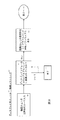
FIG. 9 is a flow diagram illustrating one embodiment of sleep software operations performed by the
一実施形態において、睡眠ソフトウェア270は、先ず、ステップ900において、睡眠GUI280を通じて(例えば、図8の睡眠GUI280)ユーザから入力を受ける。次いで、睡眠ソフトウェア270は、ステップ910において、ディスプレイモジュール100がウェアラブルバンド110に接続されているか(例えば、ウェアラブルデバイス150が取り付け状態160にあるか、又は分離状態170にあるか)を判定するチェックを行う。もしもディスプレイモジュール100がウェアラブルバンド110に接続されていないならば(例えば、ウェアラブルデバイス150が分離状態170にある)、ディスプレイモジュール100は、ステップ920において睡眠ソフトウェア270を終了させ、又はステップ910においてディスプレイモジュール100がウェアラブルバンド110に接続されているかに関して定期的にポーリングを行い続ける。もしもステップ910においてディスプレイモジュール100がウェアラブルバンド110に接続されている(例えば、ウェアラブルデバイス150が取り付け状態160にある)と判定されたなら、ステップ930において、ディスプレイモジュール100の睡眠ソフトウェア270は、睡眠GUI280を通じて決定された睡眠設定をウェアラブルバンドの睡眠ソフトウェア215に送信し、睡眠ソフトウェア215は、ステップ940において、図3に詳細に示された動作に従ってそれらを受信する。
In one embodiment, the
図9のフロー図は、ある実施形態によって行われる動作の特定の順序を図示するが、そのような順序は一実施形態であることを理解されたい(例えば、代替的な実施形態は、異なる順序で動作を行ってよく、いくつかの動作を組合わせてよく、いくつかの動作を並行して行ってよい)。 Although the flow diagram of FIG. 9 illustrates a particular order of operations performed by an embodiment, it should be understood that such an order is an embodiment (eg, an alternative embodiment has a different order). May be performed, several operations may be combined, and several operations may be performed in parallel).
図10は、本明細書において説明される全体的な方法の一実施形態を示す。一実施形態において、図10の方法は、ステップ1010において、上述のウェアラブルバンド110を提供し、これは、ウェアラブルバンドデータベース210、ウェアラブルバンド睡眠ソフトウェア215及び記憶された睡眠GUI280の選択肢を有するメモリ205と、センサ220と、振動225と、バッテリ230と、時計235と、プロセッサ290と、通信/電力ポート/モジュール130とを含む。
FIG. 10 illustrates one embodiment of the overall method described herein. In one embodiment, the method of FIG. 10 provides, at
方法は、ステップ1020において、ディスプレイモジュール基本ソフトウェア265、ディスプレイモジュール睡眠ソフトウェア270、ディスプレイモジュールデータベース275及びディスプレイモジュール睡眠GUI280を有するメモリ260と、ディスプレイ245と、センサ250と、バッテリ255と、ウェアラブルバンド通信/電力ポート/モジュール240と、プロセッサ295と、充電ポート/モジュール285とを有するディスプレイモジュール100も提供する。
In step 1020, the method includes display module
次いで、方法は、ウェアラブルバンド睡眠ソフトウェア215を実行し、ウェアラブルバンドデータベース210にデータを記憶する。ディスプレイモジュール100に接続されているなら、ウェアラブルバンド110は、ディスプレイモジュールバッテリ255から充電を受け、ウェアラブルバンドデータベース210を送り、ディスプレイモジュールの睡眠ソフトウェア270から睡眠GUI280の睡眠設定を受信し、睡眠GUI280の睡眠設定をメモリ205に記憶する。ステップ1030において、ディスプレイモジュール100に接続されていないなら、ウェアラブルバンド110は、記憶された睡眠GUI280の睡眠設定をウェアラブルバンドの時計235と突き合わせ、合致する時刻(例えば、アラーム)になったとき(バイブレータ225によって)振動してユーザにアラートを発する。
The method then executes wearable
次いで、方法は、ステップ1040において、ディスプレイモジュール基本ソフトウェア265を実行し、ディスプレイモジュールのバッテリ255からウェアラブルバンドのバッテリ230に充電を送り、ルーチン動作を実行し、ウェアラブルバンドデータベース210の少なくともサブセットを受信し、ディスプレイモジュールの未加工センサデータ及び/又はウェアラブルバンドデータベース210をディスプレイモジュールデータベース275に記憶する。
The method then executes the display module
次いで、方法は、ステップ1050において、睡眠GUI280に対するユーザ入力を決定するためにディスプレイモジュール睡眠ソフトウェア270を実行し、睡眠GUI280の選択肢をウェアラブルバンド睡眠ソフトウェア215に送る。
The method then executes the display
図10のフロー図は、ある実施形態によって行われる動作の特定の順序を図示するが、そのような順序は一実施形態にすぎないことを理解されたい(例えば、代替的な実施形態は、異なる順序で動作を行ってよく、いくつかの動作を組合わせてよく、いくつかの動作を並行して行ってよい)。 Although the flow diagram of FIG. 10 illustrates a particular order of operations performed by an embodiment, it should be understood that such an order is only one embodiment (e.g., alternative embodiments are different). The actions may be performed in order, several actions may be combined, and several actions may be performed in parallel).
本明細書において開示された実施形態は、本明細書における動作を行うための装置にも関する。そのようなコンピュータプログラムは、非一時的コンピュータ可読媒体に記憶される。マシン可読媒体は、マシン(例えば、コンピュータ)によって読み取りが可能な形態の情報を記憶するための任意の機構を含む。例えば、マシン可読(例えば、コンピュータ可読)媒体は、マシン(例えば、コンピュータ)可読記憶媒体(例えば、リードオンリーメモリ(「ROM」)、ランダムアクセスメモリ(「RAM」)、磁気ディスク記憶媒体、光学的記憶媒体、フラッシュメモリデバイス)を含む。 The embodiments disclosed herein also relate to an apparatus for performing the operations herein. Such a computer program is stored on a non-transitory computer readable medium. A machine-readable medium includes any mechanism for storing information in a form readable by a machine (eg, a computer). For example, a machine readable (eg, computer readable) medium may be a machine (eg, computer) readable storage medium (eg, read only memory (“ROM”), random access memory (“RAM”), magnetic disk storage medium, optical Storage medium, flash memory device).
前出の図面において描かれたプロセス又は方法は、ハードウェア(例えば、回路、専用ロジックなど)、ソフトウェア(例えば、非一時的コンピュータ可読媒体上に具現化されたもの)、又は両者の組み合わせを備える処理ロジックによって行われ得る。プロセス又は方法は、いくつかの連続した動作に関して上述されたが、説明された動作のいくつかは異なる順序で行われてよいことが理解されるべきである。更には、いくつかの動作は、順次にではなく、並行して行われてよい。 The processes or methods depicted in the previous drawings comprise hardware (eg, circuitry, dedicated logic, etc.), software (eg, embodied on a non-transitory computer readable medium), or a combination of both. It can be done by processing logic. Although a process or method has been described above with respect to several sequential operations, it should be understood that some of the operations described may be performed in different orders. Furthermore, some operations may be performed in parallel rather than sequentially.
いくつかの発明的な実施形態が、本明細書において説明され、示されたが、当業者は、本明細書において説明された機能を行うための、並びに/又は、本明細書において説明された結果及び/若しくは本明細書において説明された利点のうちの1つ又は複数を得るための様々な他の手段及び/又は構造体を容易に想到できよう。また、このような変更及び/又は修正の各々は、本明細書において説明される発明的な実施形態の範囲内にあると考えられる。より一般的には、当業者は、本明細書において説明される全てのパラメータ、寸法、材料及び構成は例示的なものであると意図され、実際のパラメータ、寸法、材料及び/又は構成は、発明の教示が使用される1つ又は複数の特定の用途に依存することを容易に理解されよう。当業者は、本明細書において説明される特定の発明的な実施形態の多くの等価物を、単なる通常の実験を使用して認識又は確認されよう。従って、前述の実施形態は、単なる例として提示されたものであり、添付の特許請求の範囲及びその等価物の範囲内において、発明的な実施形態は、具体的に説明された又は特許請求されたものとは違うやり方で実施可能であることを理解されたい。本開示の発明的な実施形態は、本明細書において説明される個々の特徴、システム、品物、材料、キット及び/又は方法を対象とする。加えて、2つ以上のこのような特徴、システム、品物、材料、キット及び/又は方法の任意の組み合わせも、そのような特徴、システム、品物、材料、キット及び/又は方法が相互に矛盾していないならば、本開示の発明的な範囲内に含まれる。 While several inventive embodiments have been described and illustrated herein, those skilled in the art will be able to perform the functions described herein and / or have been described herein. Various other means and / or structures for obtaining one or more of the results and / or advantages described herein will readily occur. In addition, each such change and / or modification is considered to be within the scope of the inventive embodiments described herein. More generally, one of ordinary skill in the art will appreciate that all parameters, dimensions, materials and configurations described herein are exemplary, and that the actual parameters, dimensions, materials and / or configurations are It will be readily appreciated that the teachings of the invention will depend on the particular application or applications used. Those skilled in the art will recognize or be able to ascertain using no more than routine experimentation, many equivalents to the specific inventive embodiments described herein. Accordingly, the foregoing embodiments have been presented by way of example only, and, within the scope of the appended claims and their equivalents, inventive embodiments have been specifically described or claimed. It should be understood that it can be implemented in a different way. Inventive embodiments of the present disclosure are directed to each individual feature, system, article, material, kit, and / or method described herein. In addition, any combination of two or more such features, systems, articles, materials, kits and / or methods may also contradict such features, systems, articles, materials, kits and / or methods. If not, it is included within the inventive scope of the present disclosure.
本明細書において定義され及び使用される全ての定義は、辞書的な定義、参照によって組み込まれた文書における定義、及び/又は、定義された用語の通常の意味に優先されて理解されるべきである。 All definitions defined and used herein should be understood in favor of the lexical definition, the definition in a document incorporated by reference, and / or the ordinary meaning of the defined term. is there.
本明細書及び特許請求の範囲において使用されるとき、不定冠詞「a」及び「an」は、逆のことが明確に示されない限り、「少なくとも1つ」を意味するものと理解されるべきである。 As used herein in the specification and in the claims, the indefinite articles “a” and “an” should be understood to mean “at least one” unless the contrary is clearly indicated. is there.
本明細書及び特許請求の範囲において使用されるとき、「及び/又は」という語句は、そのように結合された要素の「いずれか又は両方」、すなわち場合によっては結合的に存在し、他の場合は分離的に存在する要素を意味すると理解されるべきである。「及び/又は」を用いて列挙される複数の要素も同じように、すなわち、そのように結合された要素のうちの「1つ又は複数」と見なされるべきである。「及び/又は」の節によって具体的に特定される要素以外の要素が、具体的に特定されたそれらの要素に関連していても関連していなくても、任意選択的に存在してよい。従って、非限定的な例として、「備える(comprising)」などの非制限的言語と共に使用されるとき、「A及び/又はB」への言及は、1つの実施形態において、Aだけを指し得(任意選択的にB以外の要素を含む);別の実施形態において、Bだけを指し得(任意選択的にA以外の要素を含む);更に別の実施形態において、A及びBの両方を指し得る(任意選択的に他の要素を含む)。 As used herein in the specification and in the claims, the phrase “and / or” means “either or both” of the elements so conjoined, ie in some cases conjointly, other Cases should be understood to mean elements that exist separately. A plurality of elements listed using “and / or” should be considered the same, ie, “one or more” of the elements so conjoined. Elements other than those specifically identified by the “and / or” section may optionally be present, whether or not related to those elements specifically identified. . Thus, as a non-limiting example, a reference to “A and / or B” when used with a non-limiting language such as “comprising” may refer only to A in one embodiment. (Optionally includes elements other than B); in another embodiment, may refer only to B (optionally includes elements other than A); in yet another embodiment, both A and B may be Can point (optionally includes other elements).
本明細書及び特許請求の範囲において使用されるとき、「又は」は、上記で定義した「及び/又は」と同じ意味を有すると理解されるべきである。例えば、リストにおけるアイテムを分けるとき、「又は」又は「及び/又は」は包括的であると解釈されるべきであり、すなわち、いくつかの要素又は要素のリストのうちの少なくとも1つを含むが2つ以上の要素も含み、任意選択的に、追加的な列挙されていないアイテムも含む。「〜のうちの1つのみ」又は「〜のうちのただ1つ」などの逆のことを明確に示す用語、又は特許請求の範囲で使用される場合の「〜からなる(consisting of)」のみがいくつかの要素又は要素のリストのうちのただ1つの要素を含むことを指す。概して、本明細書において使用されるとき、用語「又は」は、「いずれか」、「〜のうちの1つ」、「〜のうちの1つのみ」、又は「〜のうちのただ1つ」等の排他的な用語を伴う場合にのみ排他的選択肢(すなわち、「一方又は他方であるが両方ではない」)を示すと解釈されるべきである。特許請求の範囲において使用されるとき、「本質的に〜からなる(consisting essentially of)」は、特許法の分野において使用される通常の意味を有する。 As used herein in the specification and in the claims, “or” should be understood to have the same meaning as “and / or” as defined above. For example, when separating items in a list, “or” or “and / or” should be construed as inclusive, ie include at least one of several elements or lists of elements. It also includes two or more elements, and optionally also includes additional non-enumerated items. Terms that clearly indicate the opposite, such as “only one of” or “only one of” or “consisting of” when used in the claims. Only refers to containing only one element of several elements or lists of elements. In general, as used herein, the term “or” means “any”, “one of”, “only one of”, or “only one of”. Should only be construed as indicating exclusive options (ie, “one or the other but not both”) with an exclusive term such as “”. As used in the claims, “consisting essentially of” has its ordinary meaning as used in the field of patent law.
本明細書及び特許請求の範囲において使用されるとき、1つ又は複数の要素のリストに言及した際の「少なくとも1つ」という語句は、要素のリストにおける要素のうちの任意の1つ又は複数から選択された少なくとも1つの要素を意味すると理解されるべきであるが、要素のリストに具体的に列挙された全ての要素のうちの少なくとも1つを必ずしも含むわけではなく、要素のリストにおける要素の任意の組み合わせを排除するものではない。この定義は、「少なくとも1つ」という語句が指す要素のリストの中で具体的に特定される要素以外の要素が、具体的に特定されたそれらの要素に関連していても関連していなくても、任意選択的に存在してよいことも許容する。従って、非限定的な例として、「A及びBのうちの少なくとも1つ」(又は同等のものとして「A又はBのうちの少なくとも1つ」、又は同等のものとして「A及び/又はBのうちの少なくとも1つ」)は、1つの実施形態において、Bは存在しない状態での少なくとも1つの、任意選択的に2つ以上の、Aを指し得(及び任意選択的にB以外の要素を含む);別の実施形態体において、Aは存在しない状態での少なくとも1つの、任意選択的に2つ以上の、Bを指し得(及び任意選択的にA以外の要素を含む);更に別の実施形態において、少なくとも1つの、任意選択的に2つ以上の、A及び少なくとも1つの、任意選択的に2つ以上の、Bを指し得る(及び任意選択的にそれ以外の要素を含む)。 As used in the specification and claims, the phrase “at least one” when referring to a list of one or more elements means any one or more of the elements in the list of elements. Should be understood to mean at least one element selected from, but does not necessarily include at least one of all elements specifically listed in the list of elements; It does not exclude any combination of. This definition is not relevant even if elements other than those specifically identified in the list of elements to which the phrase “at least one” refers are related to those elements specifically identified. However, it may be optionally present. Thus, as a non-limiting example, “at least one of A and B” (or “at least one of A or B” as equivalent, or equivalent of “at least one of A and / or B” At least one of ") in one embodiment may refer to at least one, optionally two or more, A in the absence of B (and optionally other elements than B). In another embodiment, A may refer to at least one, optionally two or more, B in the absence of (and optionally include elements other than A); May refer to at least one, optionally two or more, A and at least one, optionally two or more, B (and optionally including other elements) .
逆のことが明確に示されない限り、本明細書において特許請求される、2つ以上のステップ又は動作を含む任意の方法において、この方法のステップ又は動作の順序は、記載されたような方法のステップ又は動作の順序に必ずしも限定されないことも理解されたい。 Unless expressly stated to the contrary, in any method that includes two or more steps or actions claimed herein, the order of the steps or actions of the method is that of the method as described. It should also be understood that the order of steps or actions is not necessarily limited.
特許請求の範囲において及び上記明細書において、「備える(comprising)」、「含む(including)」、「担持する(carrying)」、「有する(having)」、「含有する(containing)」、「伴う(involving)」、「保持する(holding)」、「〜から構成される(composed of)」などの全ての移行句は、非制限的であり、すなわち、含むがそれに限定されないことを意味することを理解されたい。米国特許庁特許審査手続便覧の第2111.03項に記載される通り、「〜からなる(consisting of)」及び「本質的に〜からなる(consisting essentially of)」といった移行句のみがそれぞれ、制限的な又は半制限的な移行句である。 In the claims and in the specification above, “comprising”, “including”, “carrying”, “having”, “containing”, “accompanying” All transitional phrases such as “involving”, “holding”, “composed of”, etc. are meant to be non-limiting, ie, including but not limited to I want you to understand. Only the transitional phrases such as “consisting of” and “consisting essentially of”, respectively, are restricted, as described in US Patent Office Patent Examination Procedure Manual, Section 2111.03. Or a semi-restricted transition phrase.
Claims (15)
プログラムインストラクションを実行し、前記ウェアラブルバンドが前記分離状態又は前記取り付け状態にあるときを判定するウェアラブルバンドプロセッサと、
少なくとも前記分離状態にあるときに前記ウェアラブルバンドに電力供給し、外部電源から充電を受けるウェアラブルバンドバッテリと、
少なくとも前記分離状態にあるときに少なくとも1つのセンサ測定を行う少なくとも1つのウェアラブルバンドセンサと、
少なくとも前記分離状態にあるときにウェアラブルバンドセンサ測定値の少なくとも一部を記憶するウェアラブルバンドメモリと、
少なくとも前記取り付け状態にあるときに、前記ウェアラブルバンドセンサ測定値の少なくとも一部を前記ディスプレイモジュールに送信するウェアラブルバンド通信インターフェースと、を備える、
ウェアラブルデバイス。 A wearable device used in two states, the wearable device comprising the wearable band removably attaching the display module so that the wearable band can be configured between an attached state and a detached state, In the attached state, the wearable band is attached to the display module and communicates with the display module, and in the separated state, the wearable band is separated and separated from the display module, and the wearable band is
A wearable band processor that executes program instructions and determines when the wearable band is in the detached state or the attached state;
A wearable band battery that powers at least the wearable band when in the separated state and receives charge from an external power source;
At least one wearable band sensor that performs at least one sensor measurement when at least in the separated state;
A wearable band memory for storing at least a part of a wearable band sensor measurement value when at least in the separated state;
A wearable band communication interface that transmits at least a portion of the wearable band sensor measurements to the display module when at least in the attached state.
Wearable device.
前記プログラムインストラクションを実行し、前記ディスプレイモジュールが前記ウェアラブルバンドに取り付けられているかを判定するディスプレイモジュールプロセッサと、
前記ウェアラブルバンドから前記ウェアラブルバンドセンサ測定値の少なくとも一部を受信するディスプレイモジュール通信インターフェースと、
前記ウェアラブルバンドセンサ測定値を受信し、記憶するディスプレイモジュールメモリと、
前記ディスプレイモジュールに電力供給するディスプレイモジュールバッテリと、を備える、
請求項1に記載のウェアラブルデバイス。 The display module releasably attached to the wearable band is
A display module processor that executes the program instructions and determines whether the display module is attached to the wearable band;
A display module communication interface for receiving at least a portion of the wearable band sensor measurements from the wearable band;
Display module memory for receiving and storing the wearable band sensor measurements;
A display module battery for supplying power to the display module,
The wearable device according to claim 1.
請求項1に記載のウェアラブルデバイス。 The external power source is a display module battery.
The wearable device according to claim 1.
請求項1に記載のウェアラブルデバイス。 The external power supply is an externally connectable battery,
The wearable device according to claim 1.
請求項1に記載のウェアラブルデバイス。 The display module is a watch face;
The wearable device according to claim 1.
請求項1に記載のウェアラブルデバイス。 The display module sets at least one setting of the wearable band;
The wearable device according to claim 1.
請求項2に記載のウェアラブルデバイス。 The display module further comprises one or more display module sensors for performing one or more display module sensor measurements.
The wearable device according to claim 2.
請求項1に記載のウェアラブルデバイス。 The wearable band processor executes a wearable band instruction to generate an alarm output at a predetermined time, and the alarm output is one of vibration of the wearable band vibrator or an acoustic output from the wearable band speaker. Is,
The wearable device according to claim 1.
少なくとも前記所定のアラーム時刻を含む受信した睡眠設定入力を処理し、
前記ディスプレイモジュールが前記ウェアラブルバンドに接続されたことを判定した後、前記睡眠設定入力を前記ウェアラブルバンドに送信する、
請求項8に記載のウェアラブルデバイス。 The wearable band processor executes the wearable band instruction,
Processing the received sleep setting input including at least the predetermined alarm time;
After determining that the display module is connected to the wearable band, the sleep setting input is transmitted to the wearable band.
The wearable device according to claim 8.
請求項1に記載のウェアラブルデバイス。 Wearable band sensor measurements are based on sleep quality, sleep duration, sleep movement, sleep pattern, sleep interruption, sleep pulse, sleep blood pressure, sleep breathing, time values related to user sleep, or time values related to user wake-up. Including sleep measurements associated with at least one of them,
The wearable device according to claim 1.
前記ウェアラブルバンドが取り付け状態と分離状態との間で構成可能であるようにディスプレイモジュールを解除可能に取り付ける前記ウェアラブルバンドを提供するステップであって、前記取り付け状態において、前記ウェアラブルバンドは前記ディスプレイモジュールに取り付けられるとともに前記ディスプレイモジュールと通信し、前記分離状態において、前記ウェアラブルバンドは前記ディスプレイモジュールから分離及び離間されており、前記ウェアラブルバンドは、ウェアラブルバンドプロセッサと、前記ウェアラブルバンドに電力供給するウェアラブルバンドバッテリと、ウェアラブルバンドメモリと、少なくとも1つのウェアラブルバンドセンサとを備える、前記ウェアラブルバンドを提供するステップと、
前記ウェアラブルバンドに含まれる前記少なくとも1つのウェアラブルバンドセンサによって少なくとも1つのウェアラブルバンドセンサ測定を行うステップと、
ウェアラブルバンドセンサ測定値の少なくとも一部を前記ウェアラブルバンドメモリに記憶するステップと、
前記ウェアラブルバンドが前記ディスプレイモジュールに再接続されたかを判定するステップと、
前記ウェアラブルバンドセンサ測定値を前記ウェアラブルバンドメモリから前記ディスプレイモジュールに送信するステップと、を備える、
方法。 A method for utilizing a wearable device used in two stages, the method comprising:
Providing the wearable band releasably attaching the display module such that the wearable band is configurable between an attached state and a detached state, wherein the wearable band is attached to the display module. The wearable band is attached and communicates with the display module, and in the separated state, the wearable band is separated and separated from the display module, the wearable band comprising a wearable band processor and a wearable band battery that powers the wearable band Providing the wearable band comprising: a wearable band memory; and at least one wearable band sensor;
Performing at least one wearable band sensor measurement with the at least one wearable band sensor included in the wearable band;
Storing at least a portion of the wearable band sensor measurements in the wearable band memory;
Determining whether the wearable band is reconnected to the display module;
Transmitting the wearable band sensor measurement value from the wearable band memory to the display module,
Method.
請求項11に記載の方法。 Charging the battery of the display module of the wearable device with a power source when the display module is separated from the wearable band of the wearable device;
The method of claim 11.
請求項11に記載の方法。 Further comprising setting at least one setting of the wearable band using the display module;
The method of claim 11.
請求項11に記載の方法。 Performing at least one display module sensor measurement with at least one display module sensor;
The method of claim 11.
ウェアラブルバンドが取り付け状態と分離状態との間で構成可能であるようにディスプレイモジュールを解除可能に取り付ける当該ウェアラブルバンドを備え、前記取り付け状態において、前記ウェアラブルバンドは前記ディスプレイモジュールに取り付けられるとともに前記ディスプレイモジュールと通信し、前記分離状態において、前記ウェアラブルバンドは前記ディスプレイモジュールから分離及び離間されていて、前記ウェアラブルバンドは、
プログラムインストラクションを実行し、前記ウェアラブルバンドが前記分離状態又は前記取り付け状態にあるときを判定するウェアラブルバンドプロセッサと、
少なくとも前記分離状態にあるときに前記ウェアラブルバンドに電力供給し、外部電源から充電を受けるウェアラブルバンドバッテリと、
少なくとも前記分離状態にあるときに少なくとも1つのセンサ測定を行う少なくとも1つのウェアラブルバンドセンサと、
少なくとも前記分離状態にあるときにウェアラブルバンドセンサ測定値の少なくとも一部を記憶するウェアラブルバンドメモリと、
少なくとも前記取り付け状態にあるときに、前記ウェアラブルバンドセンサ測定値の少なくとも一部を前記ディスプレイモジュールに送信するウェアラブルバンド通信インターフェースと、を備え、前記ウェアラブルバンドに解除可能に取り付けられる前記ディスプレイモジュールは、
前記プログラムインストラクションを実行し、前記ディスプレイモジュールが前記ウェアラブルバンドに取り付けられているかを判定するディスプレイモジュールプロセッサと、
前記ウェアラブルバンドから前記ウェアラブルバンドセンサ測定値の少なくとも一部を受信するディスプレイモジュール通信インターフェースと、
前記ウェアラブルバンドセンサ測定値を受信し、記憶するディスプレイモジュールメモリと、を備える、
ウェアラブルデバイス。 A wearable device used in two states, wherein the wearable device is:
The wearable band is releasably attached so that the wearable band can be configured between an attached state and a separated state, and in the attached state, the wearable band is attached to the display module and the display module. In the separated state, the wearable band is separated and separated from the display module, and the wearable band is
A wearable band processor that executes program instructions and determines when the wearable band is in the detached state or the attached state;
A wearable band battery that powers at least the wearable band when in the separated state and receives charge from an external power source;
At least one wearable band sensor that performs at least one sensor measurement when at least in the separated state;
A wearable band memory for storing at least a part of a wearable band sensor measurement value when at least in the separated state;
A wearable band communication interface that transmits at least a part of the wearable band sensor measurement value to the display module when in the attached state, and the display module releasably attached to the wearable band comprises:
A display module processor that executes the program instructions and determines whether the display module is attached to the wearable band;
A display module communication interface for receiving at least a portion of the wearable band sensor measurements from the wearable band;
A display module memory for receiving and storing the wearable band sensor measurement value,
Wearable device.
Applications Claiming Priority (5)
| Application Number | Priority Date | Filing Date | Title |
|---|---|---|---|
| US201562135400P | 2015-03-19 | 2015-03-19 | |
| US62/135,400 | 2015-03-19 | ||
| EP15181002 | 2015-08-13 | ||
| EP15181002.5 | 2015-08-13 | ||
| PCT/EP2016/055629 WO2016146652A1 (en) | 2015-03-19 | 2016-03-16 | Wearable devices with two stage of use |
Publications (2)
| Publication Number | Publication Date |
|---|---|
| JP2018513716A true JP2018513716A (en) | 2018-05-31 |
| JP2018513716A5 JP2018513716A5 (en) | 2019-04-25 |
Family
ID=53938125
Family Applications (1)
| Application Number | Title | Priority Date | Filing Date |
|---|---|---|---|
| JP2017548255A Pending JP2018513716A (en) | 2015-03-19 | 2016-03-16 | Wearable devices used in two stages |
Country Status (5)
| Country | Link |
|---|---|
| US (1) | US20180070840A1 (en) |
| EP (1) | EP3270769A1 (en) |
| JP (1) | JP2018513716A (en) |
| CN (1) | CN107427224A (en) |
| WO (1) | WO2016146652A1 (en) |
Cited By (1)
| Publication number | Priority date | Publication date | Assignee | Title |
|---|---|---|---|---|
| US11678816B2 (en) | 2016-12-12 | 2023-06-20 | Adidas Ag | Wireless data communication and power transmission athletic apparel module |
Families Citing this family (35)
| Publication number | Priority date | Publication date | Assignee | Title |
|---|---|---|---|---|
| EP3196643A1 (en) * | 2016-01-22 | 2017-07-26 | Essilor International | A head mounted device comprising an environment sensing module |
| US10628172B2 (en) | 2016-06-27 | 2020-04-21 | Qualcomm Incorporated | Systems and methods for using distributed universal serial bus (USB) host drivers |
| US10678494B2 (en) * | 2016-06-27 | 2020-06-09 | Qualcomm Incorporated | Controlling data streams in universal serial bus (USB) systems |
| US20180059714A1 (en) * | 2016-08-23 | 2018-03-01 | Qualcomm Incorporated | Smart device with detachable band |
| FI129461B (en) * | 2016-08-25 | 2022-02-28 | Night Train Oy | Method and system for determining time window for sleep of a person |
| WO2018104308A1 (en) * | 2016-12-08 | 2018-06-14 | Boehringer Ingelheim International Gmbh | System and method for facilitating detection of a respiratory status |
| CN106725388A (en) * | 2016-12-31 | 2017-05-31 | 宁波亿诺维信息技术有限公司 | A kind of Intelligent bracelet |
| CN106725372A (en) * | 2017-01-14 | 2017-05-31 | 宁波亿诺维信息技术有限公司 | A kind of wearable Intelligent bracelet |
| KR102620178B1 (en) * | 2017-01-26 | 2024-01-03 | 삼성전자주식회사 | Electronic device and operating method thereof |
| CN108498069A (en) * | 2017-02-23 | 2018-09-07 | 光宝电子(广州)有限公司 | Wearable electronic device and its emergency help method |
| WO2018176611A1 (en) * | 2017-03-31 | 2018-10-04 | 华为技术有限公司 | Display method and electronic apparatus |
| CN106963389A (en) * | 2017-04-20 | 2017-07-21 | 上海斐讯数据通信技术有限公司 | A kind of multifunctional combination wrist wearable device |
| US11561806B2 (en) * | 2017-08-04 | 2023-01-24 | Hannes Bendfeldt | Adaptive interface for screen-based interactions |
| EP3661415A4 (en) * | 2017-08-04 | 2021-04-21 | Bendfeldt, Hannes | Adaptive interface for screen-based interactions |
| CN108271116B (en) * | 2017-12-30 | 2020-08-21 | 广州柏颐信息科技有限公司 | Real-time communication system and method for intelligent wearable device |
| JP7093989B2 (en) * | 2018-01-30 | 2022-07-01 | ライフケア技研株式会社 | Sweat amount measuring device |
| CN111819635A (en) * | 2018-03-07 | 2020-10-23 | 索尼公司 | Information processing apparatus, analysis apparatus, and information processing system |
| JP7085866B2 (en) * | 2018-03-12 | 2022-06-17 | テルモ株式会社 | Medical device system |
| GB2572412B (en) * | 2018-03-29 | 2021-03-10 | 270 Vision Ltd | Sensor apparatus |
| US20190329796A1 (en) * | 2018-04-27 | 2019-10-31 | Honda Motor Co., Ltd. | Haptic feedback system for a vehicle |
| US10685552B2 (en) * | 2018-06-26 | 2020-06-16 | Capital One Services, Llc | Condition-responsive wearable device for sensing and indicating proximity of an article with a specific characteristic |
| WO2020027706A1 (en) * | 2018-07-30 | 2020-02-06 | Off The Shelf 10106 Ab | Wearable sensor system |
| US11701293B2 (en) * | 2018-09-11 | 2023-07-18 | Encora, Inc. | Apparatus and method for reduction of neurological movement disorder symptoms using wearable device |
| US11839583B1 (en) * | 2018-09-11 | 2023-12-12 | Encora, Inc. | Apparatus and method for reduction of neurological movement disorder symptoms using wearable device |
| US20220062096A1 (en) * | 2018-09-11 | 2022-03-03 | Encora, Inc. | Apparatus and Method for Reduction of Neurological Movement Disorder Symptoms Using Wearable Device |
| US10908428B2 (en) * | 2018-09-25 | 2021-02-02 | Facebook Technologies, Llc | Multiple-device system with multiple power and data configurations |
| US11055982B1 (en) * | 2020-03-09 | 2021-07-06 | Masouda Wardak | Health condition monitoring device |
| US11844623B1 (en) * | 2021-01-06 | 2023-12-19 | Meta Platforms Technologies, Llc | Systems and methods for tracking sleep |
| CN113017591B (en) * | 2021-03-01 | 2022-10-28 | 歌尔科技有限公司 | Wearable device wearing state detection method, wearable device wearing state detection device, wearable device wearing state detection equipment and storage medium |
| US11606111B2 (en) | 2021-05-26 | 2023-03-14 | Getac Technology Corporation | Adaptive power and communication routing for body-worn devices |
| US11808823B2 (en) * | 2021-06-02 | 2023-11-07 | Getac Technology Corporation | Detection of device dislocation using power and non-powered dislocation sensors |
| US20230004129A1 (en) * | 2021-07-01 | 2023-01-05 | Apple Inc. | Watch with band device |
| US11864271B2 (en) | 2021-09-21 | 2024-01-02 | Getac Technology Corporation | Mobile device ID tracking for automatic incident data association and correlation |
| WO2023173329A1 (en) * | 2022-03-16 | 2023-09-21 | Qualcomm Incorporated | Detachable two-part wearable device |
| CN117320129A (en) * | 2022-06-23 | 2023-12-29 | 中兴通讯股份有限公司 | Control method and device of wearable device and storage medium |
Citations (4)
| Publication number | Priority date | Publication date | Assignee | Title |
|---|---|---|---|---|
| JP2013000540A (en) * | 2011-06-22 | 2013-01-07 | Hitachi Media Electoronics Co Ltd | Pulse wave detector, and pulse wave detection system |
| US20140073486A1 (en) * | 2012-09-04 | 2014-03-13 | Bobo Analytics, Inc. | Systems, devices and methods for continuous heart rate monitoring and interpretation |
| US20140239065A1 (en) * | 2011-07-18 | 2014-08-28 | Tiger T G Zhou | Wearable personal digital device with changeable bendable battery and expandable display used as standalone electronic payment card |
| WO2015031426A1 (en) * | 2013-08-27 | 2015-03-05 | Polyera Corporation | Flexible display and detection of flex state |
Family Cites Families (9)
| Publication number | Priority date | Publication date | Assignee | Title |
|---|---|---|---|---|
| US4228806A (en) * | 1978-05-25 | 1980-10-21 | International Rectifier Corporation | Sleep state inhibited wake-up alarm |
| JP3915581B2 (en) * | 2002-04-18 | 2007-05-16 | カシオ計算機株式会社 | Portable electronic devices |
| US7460899B2 (en) * | 2003-04-23 | 2008-12-02 | Quiescent, Inc. | Apparatus and method for monitoring heart rate variability |
| JP2005250442A (en) * | 2004-01-30 | 2005-09-15 | Seiko Epson Corp | Display device, method of controlling display device, control program, and recording medium |
| US7618260B2 (en) * | 2004-02-27 | 2009-11-17 | Daniel Simon R | Wearable modular interface strap |
| JP5462234B2 (en) * | 2011-11-08 | 2014-04-02 | セイコーインスツル株式会社 | Biological information detection device |
| US9244876B2 (en) * | 2012-12-20 | 2016-01-26 | Blackberry Limited | Method and apparatus pertaining to universal serial bus-based charging |
| US20150227245A1 (en) * | 2014-02-10 | 2015-08-13 | Polyera Corporation | Attachable Device with Flexible Electronic Display Orientation Detection |
| CN203898312U (en) * | 2014-06-17 | 2014-10-29 | 橙意家人科技(天津)有限公司 | Detachable watch type reflective oximeter |
-
2016
- 2016-03-16 US US15/559,070 patent/US20180070840A1/en not_active Abandoned
- 2016-03-16 EP EP16713322.2A patent/EP3270769A1/en not_active Withdrawn
- 2016-03-16 JP JP2017548255A patent/JP2018513716A/en active Pending
- 2016-03-16 WO PCT/EP2016/055629 patent/WO2016146652A1/en active Application Filing
- 2016-03-16 CN CN201680016672.9A patent/CN107427224A/en active Pending
Patent Citations (4)
| Publication number | Priority date | Publication date | Assignee | Title |
|---|---|---|---|---|
| JP2013000540A (en) * | 2011-06-22 | 2013-01-07 | Hitachi Media Electoronics Co Ltd | Pulse wave detector, and pulse wave detection system |
| US20140239065A1 (en) * | 2011-07-18 | 2014-08-28 | Tiger T G Zhou | Wearable personal digital device with changeable bendable battery and expandable display used as standalone electronic payment card |
| US20140073486A1 (en) * | 2012-09-04 | 2014-03-13 | Bobo Analytics, Inc. | Systems, devices and methods for continuous heart rate monitoring and interpretation |
| WO2015031426A1 (en) * | 2013-08-27 | 2015-03-05 | Polyera Corporation | Flexible display and detection of flex state |
Cited By (1)
| Publication number | Priority date | Publication date | Assignee | Title |
|---|---|---|---|---|
| US11678816B2 (en) | 2016-12-12 | 2023-06-20 | Adidas Ag | Wireless data communication and power transmission athletic apparel module |
Also Published As
| Publication number | Publication date |
|---|---|
| EP3270769A1 (en) | 2018-01-24 |
| WO2016146652A1 (en) | 2016-09-22 |
| US20180070840A1 (en) | 2018-03-15 |
| CN107427224A (en) | 2017-12-01 |
Similar Documents
| Publication | Publication Date | Title |
|---|---|---|
| JP2018513716A (en) | Wearable devices used in two stages | |
| US20090195350A1 (en) | Situationally Aware and Self-Configuring Electronic Data And Communication Device | |
| US10656695B2 (en) | Health wearable that automatically changes sensor reading timings | |
| US20190088100A1 (en) | Geolocation bracelet, system, and methods | |
| US10001386B2 (en) | Automatic track selection for calibration of pedometer devices | |
| Campbell et al. | From smart to cognitive phones | |
| US8515505B1 (en) | System and method of utilizing a watch as a companion device for a mobile phone | |
| CN107260178B (en) | Portable monitoring device and method of operating the same | |
| CN104949707B (en) | Motion monitoring device and method based on information push | |
| US8907783B2 (en) | Multiple-application attachment mechanism for health monitoring electronic devices | |
| US20120316471A1 (en) | Power management in a data-capable strapband | |
| WO2016151479A1 (en) | Smart sensor power management for health wearable | |
| US11287849B2 (en) | Separtable wearable device | |
| US10212505B2 (en) | Multi-point multiple sensor array for data sensing and processing system and method | |
| KR20170128201A (en) | System for locating remote objects | |
| US20170227375A1 (en) | Calibration of a primary pedometer device using a secondary pedometer device | |
| US20110128147A1 (en) | Miniature Life-saving Device | |
| KR20160105396A (en) | Battery charger related applications | |
| US9986323B2 (en) | Earphones with attachable expansion pack | |
| WO2018082227A1 (en) | Terminal and pet posture detection method and apparatus | |
| CN113892920A (en) | Wearable device wearing detection method and device and electronic device | |
| CN107408240A (en) | For providing the method and system of charge information to the user of wearable device | |
| US20190325729A1 (en) | System and Method of User Mobility Monitoring | |
| CN108433730A (en) | A kind of old man care system | |
| CN114430542A (en) | Energy saving method and terminal equipment |
Legal Events
| Date | Code | Title | Description |
|---|---|---|---|
| A521 | Request for written amendment filed |
Free format text: JAPANESE INTERMEDIATE CODE: A523 Effective date: 20190314 |
|
| A621 | Written request for application examination |
Free format text: JAPANESE INTERMEDIATE CODE: A621 Effective date: 20190314 |
|
| A977 | Report on retrieval |
Free format text: JAPANESE INTERMEDIATE CODE: A971007 Effective date: 20191226 |
|
| A131 | Notification of reasons for refusal |
Free format text: JAPANESE INTERMEDIATE CODE: A131 Effective date: 20200204 |
|
| A601 | Written request for extension of time |
Free format text: JAPANESE INTERMEDIATE CODE: A601 Effective date: 20200422 |
|
| A521 | Request for written amendment filed |
Free format text: JAPANESE INTERMEDIATE CODE: A523 Effective date: 20200729 |
|
| A131 | Notification of reasons for refusal |
Free format text: JAPANESE INTERMEDIATE CODE: A131 Effective date: 20201222 |
|
| A02 | Decision of refusal |
Free format text: JAPANESE INTERMEDIATE CODE: A02 Effective date: 20210719 |