JP2018511273A - Headphone or earphone - Google Patents
Headphone or earphone Download PDFInfo
- Publication number
- JP2018511273A JP2018511273A JP2017552986A JP2017552986A JP2018511273A JP 2018511273 A JP2018511273 A JP 2018511273A JP 2017552986 A JP2017552986 A JP 2017552986A JP 2017552986 A JP2017552986 A JP 2017552986A JP 2018511273 A JP2018511273 A JP 2018511273A
- Authority
- JP
- Japan
- Prior art keywords
- driver
- cavity
- headphone
- duct
- casing
- Prior art date
- Legal status (The legal status is an assumption and is not a legal conclusion. Google has not performed a legal analysis and makes no representation as to the accuracy of the status listed.)
- Ceased
Links
- 229910052751 metal Inorganic materials 0.000 description 16
- 239000002184 metal Substances 0.000 description 16
- 230000006835 compression Effects 0.000 description 11
- 238000007906 compression Methods 0.000 description 11
- 238000004891 communication Methods 0.000 description 9
- 230000001681 protective effect Effects 0.000 description 9
- 239000000463 material Substances 0.000 description 7
- 210000000613 ear canal Anatomy 0.000 description 6
- 230000004044 response Effects 0.000 description 6
- 210000003128 head Anatomy 0.000 description 5
- 230000004048 modification Effects 0.000 description 5
- 238000012986 modification Methods 0.000 description 5
- 239000004033 plastic Substances 0.000 description 5
- 229920003023 plastic Polymers 0.000 description 5
- 229910052782 aluminium Inorganic materials 0.000 description 4
- XAGFODPZIPBFFR-UHFFFAOYSA-N aluminium Chemical compound [Al] XAGFODPZIPBFFR-UHFFFAOYSA-N 0.000 description 4
- 229920001971 elastomer Polymers 0.000 description 4
- 239000006260 foam Substances 0.000 description 4
- RTAQQCXQSZGOHL-UHFFFAOYSA-N Titanium Chemical compound [Ti] RTAQQCXQSZGOHL-UHFFFAOYSA-N 0.000 description 3
- 238000005259 measurement Methods 0.000 description 3
- 229910000679 solder Inorganic materials 0.000 description 3
- 239000010936 titanium Substances 0.000 description 3
- 229910052719 titanium Inorganic materials 0.000 description 3
- 229920000079 Memory foam Polymers 0.000 description 2
- 239000004677 Nylon Substances 0.000 description 2
- 230000008859 change Effects 0.000 description 2
- 239000013013 elastic material Substances 0.000 description 2
- 230000007774 longterm Effects 0.000 description 2
- 239000008210 memory foam Substances 0.000 description 2
- 229920001778 nylon Polymers 0.000 description 2
- 229920001296 polysiloxane Polymers 0.000 description 2
- 238000007789 sealing Methods 0.000 description 2
- 229920004943 Delrin® Polymers 0.000 description 1
- 229930040373 Paraformaldehyde Natural products 0.000 description 1
- 239000004952 Polyamide Substances 0.000 description 1
- DHKHKXVYLBGOIT-UHFFFAOYSA-N acetaldehyde Diethyl Acetal Natural products CCOC(C)OCC DHKHKXVYLBGOIT-UHFFFAOYSA-N 0.000 description 1
- 125000002777 acetyl group Chemical class [H]C([H])([H])C(*)=O 0.000 description 1
- 230000004323 axial length Effects 0.000 description 1
- 230000009286 beneficial effect Effects 0.000 description 1
- 230000005540 biological transmission Effects 0.000 description 1
- 230000001627 detrimental effect Effects 0.000 description 1
- 210000005069 ears Anatomy 0.000 description 1
- 229920006351 engineering plastic Polymers 0.000 description 1
- 230000006872 improvement Effects 0.000 description 1
- 230000013011 mating Effects 0.000 description 1
- 230000007246 mechanism Effects 0.000 description 1
- 239000007769 metal material Substances 0.000 description 1
- 229920001084 poly(chloroprene) Polymers 0.000 description 1
- 229920002647 polyamide Polymers 0.000 description 1
- -1 polyoxymethylene Polymers 0.000 description 1
- 229920006324 polyoxymethylene Polymers 0.000 description 1
- 229920002635 polyurethane Polymers 0.000 description 1
- 239000004814 polyurethane Substances 0.000 description 1
- 229920000915 polyvinyl chloride Polymers 0.000 description 1
- 239000004800 polyvinyl chloride Substances 0.000 description 1
- 230000001902 propagating effect Effects 0.000 description 1
- 238000001228 spectrum Methods 0.000 description 1
- 229910001220 stainless steel Inorganic materials 0.000 description 1
- 239000010935 stainless steel Substances 0.000 description 1
- 230000007704 transition Effects 0.000 description 1
Images


Classifications
-
- H—ELECTRICITY
- H04—ELECTRIC COMMUNICATION TECHNIQUE
- H04R—LOUDSPEAKERS, MICROPHONES, GRAMOPHONE PICK-UPS OR LIKE ACOUSTIC ELECTROMECHANICAL TRANSDUCERS; DEAF-AID SETS; PUBLIC ADDRESS SYSTEMS
- H04R1/00—Details of transducers, loudspeakers or microphones
- H04R1/10—Earpieces; Attachments therefor ; Earphones; Monophonic headphones
- H04R1/1058—Manufacture or assembly
- H04R1/1075—Mountings of transducers in earphones or headphones
-
- H—ELECTRICITY
- H04—ELECTRIC COMMUNICATION TECHNIQUE
- H04R—LOUDSPEAKERS, MICROPHONES, GRAMOPHONE PICK-UPS OR LIKE ACOUSTIC ELECTROMECHANICAL TRANSDUCERS; DEAF-AID SETS; PUBLIC ADDRESS SYSTEMS
- H04R1/00—Details of transducers, loudspeakers or microphones
- H04R1/02—Casings; Cabinets ; Supports therefor; Mountings therein
- H04R1/025—Arrangements for fixing loudspeaker transducers, e.g. in a box, furniture
-
- H—ELECTRICITY
- H04—ELECTRIC COMMUNICATION TECHNIQUE
- H04R—LOUDSPEAKERS, MICROPHONES, GRAMOPHONE PICK-UPS OR LIKE ACOUSTIC ELECTROMECHANICAL TRANSDUCERS; DEAF-AID SETS; PUBLIC ADDRESS SYSTEMS
- H04R1/00—Details of transducers, loudspeakers or microphones
- H04R1/10—Earpieces; Attachments therefor ; Earphones; Monophonic headphones
- H04R1/1016—Earpieces of the intra-aural type
-
- H—ELECTRICITY
- H04—ELECTRIC COMMUNICATION TECHNIQUE
- H04R—LOUDSPEAKERS, MICROPHONES, GRAMOPHONE PICK-UPS OR LIKE ACOUSTIC ELECTROMECHANICAL TRANSDUCERS; DEAF-AID SETS; PUBLIC ADDRESS SYSTEMS
- H04R1/00—Details of transducers, loudspeakers or microphones
- H04R1/10—Earpieces; Attachments therefor ; Earphones; Monophonic headphones
- H04R1/1033—Cables or cables storage, e.g. cable reels
Landscapes
- Engineering & Computer Science (AREA)
- Physics & Mathematics (AREA)
- Acoustics & Sound (AREA)
- Signal Processing (AREA)
- Manufacturing & Machinery (AREA)
- Headphones And Earphones (AREA)
Abstract
ヘッドホンまたはイヤホン(10;50)がユーザの耳に装着されるようになったケーシング(12)から成り、このケーシング(12)は、ダイヤフラムを備えたドライバ(22)を包囲している。ドライバ(22)の後ろには後側クロージャ要素(15;52)か設けられ、ドライバ(22)は、その前側フェースの周囲近傍と係合した少なくとも1つの弾性要素(23)に圧着され、あるいは変形例として、2つのかかる弾性要素(23,24)相互間で締め付けられる。ケーシング(12)は、ドライバ(22)の前に設けられていて、音をユーザに耳にもたらすようになった音出口ダクト(18)と連通したキャビティを構成している。音出口ダクト(18)は、断面積がダイヤフラムの断面積の18%〜28%の絞りダクト部分を備えるのが良い。ドライバ(22)の後ろには、密閉気密キャビティが設けられるのが良く、あるいは変形例として、後側クロージャ要素(52)が音出口ダクト(18)と整列した後側出口ダクト(54)を備えても良い。【選択図】図5A headphone or earphone (10; 50) consists of a casing (12) that is adapted to be worn on the user's ear, and this casing (12) surrounds a driver (22) with a diaphragm. A rear closure element (15; 52) is provided behind the driver (22), and the driver (22) is crimped to at least one elastic element (23) engaged near the periphery of its front face, or As a variant, it is clamped between two such elastic elements (23, 24). The casing (12) is provided in front of the driver (22) and constitutes a cavity communicating with the sound outlet duct (18) adapted to bring sound to the user's ear. The sound outlet duct (18) may include a throttle duct portion having a cross-sectional area of 18% to 28% of the cross-sectional area of the diaphragm. The driver (22) may be provided with a hermetically sealed airtight cavity behind the driver (22) or, alternatively, the rear closure element (52) comprises a rear outlet duct (54) aligned with the sound outlet duct (18). May be. [Selection] Figure 5
Description
本発明は、ヘッドホンまたはイヤホン、特にユーザの耳の端部内にユーザによって入れられるイヤホン(これが全てではない)に関する。 The present invention relates to headphones or earphones, particularly earphones (not all) that can be placed by a user in the end of the user's ear.
ヘッドホンまたはイヤホンは、近くにいる他人に聞こえないように音楽またはラジオを聞きたい人によって用いられる場合が多い。イヤホンは、「耳内モニタ(in-ear monitor)」、英語表記の頭文字をとってIEM、または「耳内ヘッドホン(in-ear headphone)」と呼ばれる場合があり、かかるイヤホンは、ユーザの外耳道内に嵌まり込むよう寸法決めされているのが良く、その結果、これらイヤホンは、使用中にほぼ見えないようにすることができる。これとは対照的に、ヘッドホンは、典型的には、頭の頂部上を通るバンドによって支持された状態で耳の外側に被さり、したがって、相当大きい。一例を挙げると、イヤホンは、10mm未満、例えば8mmまたは5mmの直径のダイヤフラムを有する場合があり、これに対し、ヘッドホンは、典型的には60mm未満、例えば35mmまたは20mmのダイヤフラムを有する場合がある。かかる場合、音源は、従来型ラウドスピーカよりも極めて小さく、その結果、可聴音スペクトル全体にわたって正確な音の再現を達成する上での問題が生じる場合がある。 Headphones or earphones are often used by people who want to listen to music or radio so that others nearby do not hear it. Earphones are sometimes referred to as “in-ear monitors”, IEMs for English initials, or “in-ear headphones”, and such earphones may be referred to as the user's ear canal. The earphones may be dimensioned to fit within, so that these earphones may be substantially invisible during use. In contrast, headphones typically cover the outside of the ear, supported by a band passing over the top of the head, and are therefore quite large. As an example, earphones may have a diaphragm with a diameter of less than 10 mm, for example 8 mm or 5 mm, whereas headphones typically have a diaphragm with a diameter of less than 60 mm, for example 35 mm or 20 mm. . In such a case, the sound source is much smaller than a conventional loudspeaker, which can result in problems in achieving accurate sound reproduction over the entire audible sound spectrum.
本発明によれば、ユーザの耳に装着するようになったケーシングを有するヘッドホンまたはイヤホンであって、ケーシングは、ドライバを位置決めするキャビティを構成するとともに音をユーザの耳にもたらすようキャビティの前側端部と連通した音出口ダクトを構成し、ケーシングは、後側クロージャ要素を備え、ケーシングは、ドライバを包囲し、ドライバの前側フェースにはダイヤフラムが設けられ、ドライバは、ドライバ位置決めキャビティをドライバの後ろに位置する後側キャビティとドライバの前側に位置する前側キャビティに分割し、前側キャビティは、音出口ダクトと連通し、ヘッドホンまたはイヤホンは、少なくとも1つの弾性要素を更に有し、ドライバは、この前側フェースの周囲近傍と係合した弾性要素と後側フェースに係合した後側要素との間で締め付けられ、前側フェースに係合した弾性要素は、前側キャビティの端フェースとドライバの前側フェースとの間で圧縮されていることを特徴とするヘッドホンまたはイヤホンが提供される。 According to the present invention, a headphone or an earphone having a casing adapted to be worn on a user's ear, wherein the casing forms a cavity for positioning a driver and provides a sound to the user's ear. The casing is provided with a rear closure element, the casing surrounds the driver, the front face of the driver is provided with a diaphragm, and the driver has a driver positioning cavity behind the driver. The front cavity is located in front of the driver and the front cavity communicates with the sound outlet duct, the headphone or the earphone further comprising at least one elastic element, and the driver Elastic element and rear face engaged with the vicinity of the face Headphones or earphones characterized in that the elastic element that is tightened between the rear element engaged with the front face and that is engaged with the front face is compressed between the end face of the front cavity and the front face of the driver Is provided.
弾性要素は、Oリングシールまたはガスケットであるのが良く、かかる弾性要素は、ドライバの前側フェースの周囲を前側キャビティの端フェースに封着するのが良い。 The elastic element may be an O-ring seal or a gasket, and such elastic element may seal around the front face of the driver to the end face of the front cavity.
一オプションでは、後側要素は、弾性要素でもあり、後側要素は、ドライバの後側フェースの周囲近傍に係合し、後側要素は、この場合、ドライバの後側フェースと後側キャビティの端フェースとの間で圧縮されるのが良い。 In one option, the rear element is also an elastic element, and the rear element engages near the periphery of the driver's rear face, which in this case is the driver's rear face and the rear cavity. It is good to compress between end faces.
後側クロージャ要素は、ねじ式連結部によってケーシングに連結されるのが良く、あるいは、ラッチまたはクリップ機構体によって固定されても良い。特に、後側クロージャ要素は、少なくとも部分的にキャビティの端部分内に嵌まり込むのが良く、ねじ式連結部は、キャビティの端部分の内壁に設けられたねじ山を含むのが良い。 The rear closure element may be connected to the casing by a screw connection or may be fixed by a latch or clip mechanism. In particular, the rear closure element may fit at least partially within the end portion of the cavity, and the threaded connection may include a thread provided on the inner wall of the end portion of the cavity.
音出口ダクトは、好ましくは、テーパ付きダクト部分を含み、このテーパ付きダクト部分は、キャビティの前側端部が音出口ダクトと連通している場所であるのが良く、テーパは、例えば、音出口ダクトの長手方向軸線に対して40°〜50°、例えば45°に傾けられるのが良い。 The sound outlet duct preferably includes a tapered duct portion, which may be where the front end of the cavity communicates with the sound outlet duct, where the taper is, for example, a sound outlet. It may be inclined at 40 ° to 50 °, for example 45 ° with respect to the longitudinal axis of the duct.
音出口ダクトは、ダイヤフラムよりも幅の狭いものであり、かかる音出口ダクトは、断面積がダイヤフラムの断面積の19%〜30%の絞りダクト部分を備えるのが良い。絞りダクト部分は、最も小さな断面積の音出口ダクトの部分である。ダイヤフラムと絞りダクト部分の両方が円形断面のものである場合、この制約は、絞りダクト部分の直径がダイヤフラムの直径の約44%〜55%であることが必要であるという要件と等価であり、最適値は、ダイヤフラムの直径の約49%である。 The sound outlet duct is narrower than the diaphragm, and the sound outlet duct may include a throttle duct portion having a cross-sectional area of 19% to 30% of the cross-sectional area of the diaphragm. The throttle duct portion is the portion of the sound outlet duct having the smallest cross-sectional area. If both the diaphragm and the restrictor duct portion are of circular cross section, this constraint is equivalent to the requirement that the restrictor duct portion diameter be approximately 44% to 55% of the diaphragm diameter; The optimum value is about 49% of the diameter of the diaphragm.
後側キャビティは、密閉気密キャビティであるのが良く、あるいは変形例として、後側キャビティは、後側出口ポートを備えても良い。後側出口ポートは、これが設けられる場合、音出口ダクトと軸方向に整列するのが良く、望ましくは、第2の出口ダクトの絞りダクト部分と同一の断面積の後側絞りダクト部分を備える。これらの特徴については本発明の他の観点と関連して以下に詳細に説明する。 The rear cavity may be a hermetically sealed airtight cavity, or alternatively, the rear cavity may include a rear outlet port. The rear outlet port, if provided, may be axially aligned with the sound outlet duct, and preferably comprises a rear throttle duct portion having the same cross-sectional area as the throttle duct portion of the second outlet duct. These features are described in detail below in connection with other aspects of the invention.
理解されるように、ドライバへの電気接続が行われなければならない。これには、ドライバの後部に接続されるケーブルが必要である。これは、ケーブル案内を利用するのが良い。 As will be appreciated, an electrical connection to the driver must be made. This requires a cable connected to the back of the driver. For this, it is better to use a cable guide.
別の観点では、本発明は、イヤホン、ヘッドホンまたはマイクロホンのケーシングに用いられるケーブル案内を提供し、このケーシングは、ドライバに連結可能なケーブルを導入させるスロットを構成する壁を備えた円筒形キャビティを有し、ケーシングは、後側クロージャ要素を備え、ヘッドホンまたはイヤホンは、スロット内に位置することができる入口ダクトを構成するケーブル案内と、円筒形キャビティ内に軸方向に嵌まり込む締め付けリングとを更に有し、ケーブル案内は、2つの合致する部品、すなわち、入口ダクトの一方の側部を構成するとともに締め付けリングの一方のフェースの弧状部分を構成して弧状部分の端相互間に周方向隙間を生じさせる第1の部品および入口ダクトの他方の側部を構成するとともに締め付けリングの残部を構成する第2の部品を含み、2つの部品が互いに合わされると、締め付けリングは、実質的に連続した前側フェースおよび実質的に連続した後側フェースを有する。 In another aspect, the present invention provides a cable guide for use in an earphone, headphone, or microphone casing that includes a cylindrical cavity with a wall defining a slot for introducing a cable connectable to a driver. The casing includes a rear closure element, the headphones or earphones having a cable guide that forms an inlet duct that can be located in the slot, and a clamping ring that fits axially into the cylindrical cavity. The cable guide further comprises a circumferential gap between the ends of the arcuate portions constituting two arcing portions of one face of the clamping ring and constituting one side of the inlet duct. The first part that produces the first side and the other side of the inlet duct and the fastening ring It comprises a second part constituting the remainder, with the two parts are mated together, the clamping ring is a substantially continuous front face and a substantially side face after continuous.
組み立ての際、ケーブルをケーブル案内に通す必要がなく、このようにケーブル案内にケーブルを通すことは、確かなこととして言えば、ケーブルの端部がケーシング内の電気音響変換器、例えばドライバにはんだ付けされる場合に困難な場合がある。ケーブルを弧状部分の端相互間の周方向隙間に通してケーブルをケーブル案内の第1の部品中に布設し、次にケーブル案内の第1の部品と第2の部品を互いに合致させることが必要であるに過ぎない。第1の部品と第2の部品は、組み合わせ状態で、実質的に連続した前側フェースおよび実質的に連続した後側フェースを有する締め付けリングを形成する。 When assembling, it is not necessary to pass the cable through the cable guide, and passing the cable through the cable guide in this way is, for certainty, the end of the cable soldered to an electroacoustic transducer in the casing, for example a driver. It may be difficult to attach. It is necessary to route the cable through the circumferential gap between the ends of the arcuate portion and lay the cable in the first part of the cable guide, and then match the first and second parts of the cable guide to each other It is only. The first part and the second part in combination form a clamping ring having a substantially continuous front face and a substantially continuous rear face.
一実施形態では、ケーブル案内の第2の部品は、締め付けリングの後側フェースを形成するリングを構成し、第1の部品の弧状部分の端相互間の周方向隙間内に嵌まり込む弧状部分が後側フェースから突き出ている。変形実施形態では、第1の部分は、弧状部分を備えるだけでなく後方に突き出た弧状部品をも備え、第2の部分は、後方に突き出た弧状部品が嵌まり込む隙間を備えた弧状リング部分を備える。 In one embodiment, the second part of the cable guide constitutes a ring that forms the rear face of the clamping ring, and the arcuate part that fits into the circumferential gap between the ends of the arcuate part of the first part Protrudes from the rear face. In an alternative embodiment, the first part comprises not only an arcuate part but also an arcuate part protruding backwards, and the second part is an arcuate ring with a gap into which the arcuate part protruding backwards fits. With parts.
それ故、ケーシング内にドライバが設けられている場合、ドライバに通じるケーブルをケーブル案内に通すことができ、すると、後側クロージャ要素は、締め付けリングの後側フェースへの圧力をもたらすことができる。締め付けリングにより、実質的に一様な圧力がケーブル案内によりケーブルそれ自体が圧縮されていないようにされている間、ドライバの周囲全体に沿ってぐるりと加えることができる。 Therefore, if a driver is provided in the casing, the cable leading to the driver can be passed through the cable guide, and the rear closure element can then exert pressure on the rear face of the clamping ring. The tightening ring allows a substantially uniform pressure to be applied around the entire circumference of the driver while the cable guide prevents the cable itself from being compressed.
入口ダクトは、好ましくは、ケーブルを締め付けるクランプ、例えば内側隆起部を備え、その結果、ケーブルに加わる張力が、ケーブルがドライバに固定されているはんだ継手に直接作用しないで、ケーブル案内、したがってケーブルに伝えられる。 The inlet duct preferably comprises a clamp that clamps the cable, e.g. an inner ridge, so that the tension applied to the cable does not act directly on the solder joint where the cable is secured to the driver, but to the cable guide and thus to the cable. Reportedly.
かかるケーブル案内は、場合によっては、金属で作られるのが良い。より代表的には、ケーブル案内は、プラスチック材料、例えばポリウレタン、ポリ塩化ビニル、ナイロン(ポリアミド)およびデルリン(商標)(ポリオキシメチレンまたはアセタール)で作られる。プラスチックの選択は、特定の状況で必要な使用および可撓性で決まる場合がある。大きなケーシングが大きなドライバを収容する場合、より軟質のプラスチックを使用して入口ダクトにある程度の融通性が得られるようにすることが望ましい場合があり、これに対して、ケーシングが小さい場合、硬質のプラスチックを用いることが好ましい。ケーブル案内は、プラスチック材料で作られている場合、代表的には、ドライバの周囲をケーシングに封着するのを助けるある程度の弾性を提供する。その結果、この場合、一般的に言えば、ドライバの後ろにガスケットまたはOリングを用いる必要がない。 Such cable guides may be made of metal in some cases. More typically, cable guides are made of plastic materials such as polyurethane, polyvinyl chloride, nylon (polyamide) and Delrin ™ (polyoxymethylene or acetal). The choice of plastic may depend on the use and flexibility required in a particular situation. When a large casing accommodates a large driver, it may be desirable to use a softer plastic to provide some flexibility for the inlet duct, whereas when the casing is small, It is preferable to use plastic. When the cable guide is made of a plastic material, it typically provides a degree of elasticity that helps to seal the periphery of the driver to the casing. As a result, in this case, generally speaking, it is not necessary to use a gasket or O-ring behind the driver.
本発明の別の観点によれば、ユーザの耳に装着するようになったケーシングを有するヘッドホンまたはイヤホンが提供され、ケーシングは、ダイヤフラムを備えたドライバを包囲するとともにドライバの後ろに密封気密キャビティおよびドライバの前に設けられていて音をユーザの耳にもたらすようになった音出口ダクトと連通したキャビティを構成し、音出口ダクトは、断面積がダイヤフラムの断面積の19%〜30%の絞りダクト部分を備えている。 In accordance with another aspect of the present invention, there is provided a headphone or earphone having a casing adapted to be worn on a user's ear, the casing surrounding a driver with a diaphragm and a sealed airtight cavity behind the driver and A cavity that communicates with a sound outlet duct that is provided in front of the driver and is configured to bring sound to the user's ear is configured. It has a duct part.
上述したように絞りダクト部分は、最小断面積の音出口ダクトの部分である。ダイヤフラムと絞りダクト部分の両方が円形断面のものである場合、この制約は、絞りダクト部分の直径がダイヤフラムの直径の約44〜55%であるという要件と等価であり、最適値は、ダイヤフラム直径の約49%である。 As described above, the throttle duct portion is the portion of the sound outlet duct having the minimum cross-sectional area. If both the diaphragm and the restrictor duct portion are of circular cross section, this constraint is equivalent to the requirement that the restrictor duct portion diameter be approximately 44-55% of the diaphragm diameter, with the optimum value being the diaphragm diameter. Of about 49%.
好ましくは、ドライバは、ケーシングに封着される。ドライバは、例えば、この前側フェースの周囲近傍と係合するシールにより締め付けられることによってケーシングに封着されるのが良く、シールは、ドライバの前に位置するキャビティの端フェースとドライバのフェースとの間で圧縮される。確かなこととして、ドライバは、それぞれ前側フェースおよび後側フェースに係合する2つのかかるシール相互間で締め付けられるのが良い。Oリングシールまたはガスケットが設けられるのが良く、かかるOリングシールまたはガスケットは、形状がドライバの外側形状に一致し、例えば、円形リング状であり、この場合、ケーシングとドライバは、円筒形である。これらのことにより、ドライバは、全体として、ケーシング内で振動せずまたはがたつかないようになる。 Preferably, the driver is sealed to the casing. The driver may be sealed to the casing, for example, by being tightened by a seal that engages the vicinity of the periphery of the front face, and the seal is between the end face of the cavity located in front of the driver and the face of the driver. Compressed between. Certainly, the driver may be clamped between two such seals that engage the front and rear faces, respectively. O-ring seals or gaskets may be provided, such O-ring seals or gaskets have a shape that matches the outer shape of the driver, for example a circular ring shape, in which case the casing and the driver are cylindrical. . These prevent the driver from vibrating or rattling in the casing as a whole.
ドライバの前に位置するキャビティ、すなわち前側キャビティは、深さが3mm未満であるのが良く、ケーシングは、好ましくは、前側キャビティの深さを最小限に抑えるよう配置されているが、明らかなこととして、前側キャビティの端壁は、ドライバからの音の伝達を妨げるほど密接していてはならない。 The cavity located in front of the driver, i.e. the front cavity, should be less than 3 mm deep, and the casing is preferably arranged to minimize the depth of the front cavity, but it should be clear As such, the end walls of the front cavity should not be so close that they prevent transmission of sound from the driver.
ドライバの後ろに位置する気密キャビティ(すなわち、後側キャビティ)もまた、深さが3mm未満であるのが良く、好ましくは深さが2mm以下である。前側キャビティの場合と同様、ドライバは、圧縮シールによって後側キャビティの反対側の端から間隔を置いて配置されるのが良く、その結果、圧縮シールの厚さは、後側キャビティの深さを定める。後側キャビティは、前側キャビティと同一深さのものであっても良く、あるいは、前側キャビティよりも深くなくても良い。理解されるように、ドライバは、代表的には、ダイヤフラムの後ろに位置する少なくとも1つの通気穴を有し、この通気穴は、ドライバの後ろの気密キャビティ、すなわち後側キャビティと連通し、したがって、ドライバ内に位置するがダイヤフラムの後ろに位置する自由空間と連通状態にある。極端な場合、後側キャビティは、したがって、ゼロ深さのものであっても良く、それによりドライバの後部を封止するに過ぎないものであっても良く、その結果、ダイヤフラムの後ろに位置するドライバ内の自由空間は、気密状態になる。しかしながら、ドライバの後部に電気接点を作ることが通常は必要なので、代表的には、所要の電気接続部を収容するのに十分に深いが、これよりも深くはない後側キャビティを提供することが有利である。電気接続部は、上述したようなケーブル案内を用いるのが良い。 The hermetic cavity located behind the driver (i.e., the rear cavity) should also be less than 3 mm deep, and preferably less than 2 mm deep. As with the front cavity, the driver may be spaced from the opposite end of the rear cavity by a compression seal so that the thickness of the compression seal reduces the depth of the rear cavity. Determine. The rear cavity may be the same depth as the front cavity, or may not be deeper than the front cavity. As will be appreciated, a driver typically has at least one vent located behind the diaphragm, which communicates with an airtight cavity, i.e., a rear cavity, behind the driver, and thus , Located in the driver but in communication with a free space located behind the diaphragm. In the extreme case, the rear cavity may therefore be of zero depth, thereby only sealing the rear part of the driver, so that it is located behind the diaphragm The free space in the driver is airtight. However, since it is usually necessary to make electrical contacts at the back of the driver, typically provide a back cavity that is deep enough to accommodate the required electrical connections, but not deeper than this. Is advantageous. The electrical connection may use a cable guide as described above.
音出口ダクトの絞りダクト部分をドライバの後ろに位置する気密キャビティと組み合わせて設けることにより、ダイヤフラムの前側内とダイヤフラム後側の両方の圧力増大が生じそうであり、これらが互いに打ち消しあうことが推定される。これは驚くべきこととして、ドライバの動作範囲を拡大することが判明しており、したがって、これにより例えば20Hz〜20kHzの可聴周波数範囲全体にわたる線形応答を提供することができる。使用中、ヘッドホンまたはイヤホンが耳に当てて保持されまたは耳の中に保持されると、音出口ダクトが耳それ自体によって画定されまたは耳それ自体の中に位置する密閉空間中に通じるので、ダイヤフラムの後ろの圧力とダイヤフロム前の圧力の釣り合いが効果的に得られることが推定される。絞りダクト部分の横断面積がダイヤフラムの横断面積の30%を超える場合、低音周波数と高音周波数の両方の再現の有効性が低くなり、これに対し、絞りダクト部分の断面積がダイヤフラムの断面積の19%未満である場合、おそらくは過剰の音圧に起因して低音と高音のゆがみが生じる。 Estimating that the throttle duct part of the sound outlet duct combined with the airtight cavity located behind the driver is likely to cause pressure increase both inside the diaphragm and behind the diaphragm, and these will cancel each other Is done. This has surprisingly been found to increase the operating range of the driver, and thus can provide a linear response over the entire audible frequency range of, for example, 20 Hz to 20 kHz. In use, when the headphones or earphones are held against or held in the ear, the sound outlet duct leads into a sealed space defined by or located within the ear itself, so that the diaphragm It is presumed that the balance between the pressure behind and the pressure before the diaphragm can be obtained effectively. When the cross-sectional area of the throttle duct part exceeds 30% of the diaphragm cross-sectional area, the effectiveness of reproducing both the low frequency and the high frequency is reduced, whereas the cross-sectional area of the throttle duct part is smaller than the cross-sectional area of the diaphragm. If it is less than 19%, bass and treble distortion will occur, possibly due to excessive sound pressure.
本発明の別の観点によれば、ユーザの耳に装着するようになったケーシングを有するヘッドホンまたはイヤホンが提供され、ケーシングは、ドライバ位置決めキャビティまたはチャンバを備え、このキャビティまたはチャンバの少なくとも一部分は、円筒形であり、ヘッドホンまたはイヤホンは、チャンバの円筒形部分内に配置されたダイヤフラム付きのドライバを有し、したがって、ドライバの後ろには後側キャビティが設けられるとともにドライバの前側には前側キャビティが設けられ、前側キャビティは、音をユーザの耳にもたらすようになった前側出口ダクトと連通し、前側出口ダクトは、ダイヤフラムの断面積よりも小さい断面積を有する前側絞りダクト部分を備え、後側キャビティは、ダイヤフラムの断面積よりも小さい断面積を有する後側絞りダクト部分を備えた後側出口ダクトと連通し、後側出口ダクトとチャンバの円筒形部分と、前側出口ダクトは、同軸であり、後側出口ダクトと前側出口ダクトは、互いに整列し、前側絞りダクト部分と後側絞りダクト部分は、同一の断面積を有する。 According to another aspect of the present invention, there is provided a headphone or earphone having a casing adapted to be worn on a user's ear, the casing comprising a driver positioning cavity or chamber, at least a portion of the cavity or chamber being The headphone or earphone has a driver with a diaphragm disposed in the cylindrical part of the chamber, so that a rear cavity is provided behind the driver and a front cavity is provided in front of the driver. A front cavity is provided that communicates with a front outlet duct adapted to bring sound to a user's ear, the front outlet duct having a front throttle duct portion having a cross-sectional area that is smaller than a cross-sectional area of the diaphragm; The cavity has a cross-sectional area that is smaller than the cross-sectional area of the diaphragm. In communication with a rear outlet duct having a rear throttle duct portion, the rear outlet duct and the cylindrical portion of the chamber, and the front outlet duct are coaxial, the rear outlet duct and the front outlet duct are aligned with each other The front throttle duct portion and the rear throttle duct portion have the same cross-sectional area.
好ましくは、ドライバは、その前側フェースの周囲近傍に係合する弾性要素で締め付けられ、弾性要素は、ドライバと前側キャビティの端フェースの間で圧縮される。また、ドライバの後側フェースの周囲近傍と係合した弾性要素もまた設けられるのが良く、その結果、ドライバは、2つのかかる弾性要素相互間で締め付けられる。弾性要素は、弾性をもたらすOリングまたはガスケットから成るのが良い。 Preferably, the driver is clamped with an elastic element that engages near the periphery of its front face, and the elastic element is compressed between the driver and the end face of the front cavity. An elastic element engaged with the vicinity of the periphery of the driver's rear face may also be provided, so that the driver is clamped between two such elastic elements. The elastic element may consist of an O-ring or gasket that provides elasticity.
本発明の各観点では、長い軸方向長さを提供するよう少なくとも1つの弾性要素が剛性であるアイテムと弾性であるアイテムを組み合わせることができる。それ故、Oリングまたはガスケットは、ドライバのフェースと接触状態にあっても良く、あるいは、剛性要素、例えば金属リングまたはワッシャによりドライバのフェースから間隔を置いて配置されても良い。ドライバは、弾性要素のうちの少なくとも1つによってケーシングに効果的に封着されるのが良い。弾性要素は、ドライバが全体としてケーシング内で振動せずまたはがたつかないようにする。 In each aspect of the present invention, an item in which at least one elastic element is rigid and an item in elastic can be combined to provide a long axial length. Thus, the O-ring or gasket may be in contact with the driver's face, or may be spaced from the driver's face by a rigid element such as a metal ring or washer. The driver may be effectively sealed to the casing by at least one of the elastic elements. The elastic element prevents the driver from vibrating or rattling in the casing as a whole.
本発明の各観点では、ドライバは、圧縮シールによって前側キャビティの反対側の端から間隔を置いて設けられるのが良く、その結果、圧縮シールの厚さが前側キャビティの深さを定めるようになる。各形式のケーシングでは、ドライバへの電気接続部が上述したようなケーブル案内を用いて作られるのが良いことが理解されよう。 In each aspect of the present invention, the driver may be spaced from the opposite end of the front cavity by a compression seal so that the thickness of the compression seal defines the depth of the front cavity. . It will be appreciated that in each type of casing, the electrical connection to the driver may be made using a cable guide as described above.
絞りダクト部分は、各場合において、最も小さい断面積の出口ダクトの部分である。音出口ダクトは、望ましくは、ダイヤフラムの幅全体からの音を絞りダクト部分中に効果的に結合するためにドライバの最も近くに位置する端のところに設けられていて絞りダクト部分まで先細になった幅広部分を有する。これは、直線テーパを有するのが良い。絞りダクト部分は、ダイヤフラムの断面積の20%〜29%の断面積を有するのが良い。音出口ダクトは、ドライバから見て最も遠くの端のところに幅広部分を更に有するのが良い。 The throttle duct part is in each case the part of the outlet duct with the smallest cross-sectional area. The sound outlet duct is preferably provided at the end closest to the driver and tapers to the throttle duct portion to effectively couple the sound from the entire diaphragm width into the throttle duct portion. With a wide part. This may have a linear taper. The restriction duct portion may have a cross-sectional area of 20% to 29% of the cross-sectional area of the diaphragm. The sound outlet duct may further have a wide portion at the farthest end as viewed from the driver.
後側出口ダクトと前側出口ダクトの両方が提供される場合には、かかる出口ダクトまたはかかる出口ダクトが1つだけ設けられる場合には音出口ダクトは、代表的には、各々がドライバ位置決めキャビティの円筒形部分の長手方向軸線を中心とする回転面である表面によって定められる。各場合、出口ダクトは、円筒形であっても良くまたはこれらの長さに沿って直径が変化していても良く、例えば、一端または各端のところに直線またはベル形テーパを有しても良い。この出口ダクトまたは各出口ダクトがドライバ位置決めキャビティと連通する場合、望ましくは、出口ダクトの長手方向軸線に対して40°〜50°、例えば45°の角度をなして傾けられる場合のあるテーパ付き移行部が設けられる。各場合において、絞りダクト部分は、直線テーパまたはベル形テーパを有するのが良い。また、ドライバから見て最も遠くの端には幅広部分が設けられるのが良い。 Where both a rear outlet duct and a front outlet duct are provided, if such outlet duct or only one such outlet duct is provided, the sound outlet ducts are typically each of the driver positioning cavities. It is defined by a surface that is a plane of rotation about the longitudinal axis of the cylindrical portion. In each case, the outlet duct may be cylindrical or may vary in diameter along their length, for example having a straight or bell taper at one or each end. good. When this outlet duct or each outlet duct is in communication with a driver positioning cavity, it is preferably a tapered transition that may be tilted at an angle of 40 ° to 50 °, for example 45 °, with respect to the longitudinal axis of the outlet duct. Parts are provided. In each case, the throttle duct portion may have a linear taper or a bell taper. Further, it is preferable that a wide portion is provided at the farthest end as viewed from the driver.
後側出口ダクトと前側出口ダクトの両方が設けられる実施形態では、後側キャビティはまた、深さが3mm未満であるのが良く、好ましくは深さが2mm以下である。前側キャビティの場合と同様、ドライバは、圧縮シールによって後側キャビティの端から間隔を置いて設けられ、その結果、圧縮シールの厚さが後側キャビティの深さを定めることができるようになっている。後側キャビティは、前側キャビティと同一深さのものであっても良く、あるいは、前側キャビティよりも深さが小さくても良い。上述したように、ドライバは、代表的には、ダイヤフラムの後ろに位置していて後側キャビティと連通した少なくとも1つの通気穴を有することが理解され、したがって、後側キャビティは、ドライバ内に位置するがダイヤフラムの後側に位置する自由空間と連通状態にある。ドライバの後部に電気接点を作ることが通常は必要であり、従って、代表的には、少なくとも所要の電気接続部を収容するのに十分に深い後側キャビティを提供することが有利である。後側出口ダクトは、望ましくは、ドライバの後部からの音を絞りダクト部分中に効果的に結合するためにドライバの最も近くに位置する端のところに設けられていて絞りダクト部分まで先細になった幅広部分を有する。絞りダクト部分は、直線テーパまたはベル形テーパを有するのが良い。後側出口ダクトは、ドライバから最も遠く離れた端のところに幅広部分を更に有するのが良い。 In embodiments where both a rear outlet duct and a front outlet duct are provided, the rear cavity may also be less than 3 mm deep, and preferably less than 2 mm deep. As with the front cavity, the driver is spaced from the end of the rear cavity by a compression seal so that the thickness of the compression seal can determine the depth of the rear cavity. Yes. The rear cavity may have the same depth as the front cavity, or may be smaller in depth than the front cavity. As described above, it is understood that the driver typically has at least one vent hole located behind the diaphragm and in communication with the rear cavity, so that the rear cavity is located within the driver. However, it is in communication with the free space located behind the diaphragm. It is usually necessary to make electrical contacts at the back of the driver, and therefore it is typically advantageous to provide a rear cavity that is deep enough to accommodate at least the required electrical connections. The rear outlet duct is preferably provided at the end closest to the driver and tapers to the throttle duct portion to effectively couple the sound from the rear of the driver into the throttle duct portion. With a wide part. The restrictor duct portion may have a linear taper or a bell-shaped taper. The rear outlet duct may further have a wide portion at the end farthest from the driver.
一実施形態では、前側出口ダクトと後側出口ダクトは、同一の長手方向輪郭形状を有する。 In one embodiment, the front outlet duct and the rear outlet duct have the same longitudinal profile.
出口ダクトをドライバの前後に対称に配置することによりドライバの動作に有益な作用が提供され、それにより可聴周波数範囲全体、例えば20Hz〜20kHzにわたってより一貫した応答が保証される。 The symmetrical arrangement of the outlet ducts before and after the driver provides a beneficial effect on driver operation, thereby ensuring a more consistent response over the entire audible frequency range, for example 20 Hz to 20 kHz.
本発明の各観点では、ケーシングは、動作中実質的に剛性でなければならず、したがって、ドライバは、確実に定位置に保持され、ケーシングは、振動しない。ケーシングは、例えば、アルミニウム、ステンレス鋼またはチタンで作られるのが良く、ただし、他の材料の使用もまた適している場合がある。ドライバは、上述したように2つの互いに反対側のシールによってケーシング内に支持されるのが良い。ドライバの後ろに気密キャビティが設けられる実施形態では、この特徴および更に剛性ケーシングは、ヘッドホンまたはイヤホンの後部からは音が出ないようにする。 In each aspect of the invention, the casing must be substantially rigid during operation, thus ensuring that the driver is held in place and the casing does not vibrate. The casing may be made of, for example, aluminum, stainless steel or titanium, although the use of other materials may also be suitable. The driver may be supported in the casing by two opposite seals as described above. In embodiments where an airtight cavity is provided behind the driver, this feature and the more rigid casing prevents sound from coming from the back of the headphones or earphones.
ヘッドホンの場合、ケーシングは、代表的には、ユーザの頭の上のストラップによって支持され、かかるケーシングは、イヤクッションまたはフォームパッドを備えるのが良い。イヤホンの場合、ケーシングは、代表的には、イヤホンについて通常用いられているように外耳道に密着するフォームバッドまたはイヤホン先端部を備える。 In the case of headphones, the casing is typically supported by a strap on the user's head, and such casing may comprise an ear cushion or foam pad. In the case of earphones, the casing typically includes a foam bud or earphone tip that is in close contact with the ear canal, as is commonly used for earphones.
次に、添付の図面を参照して本発明について更に具体的に説明するが、これは例示であるに過ぎない。 The present invention will now be described more specifically with reference to the accompanying drawings, but this is merely an example.
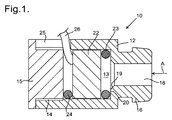
図1を参照すると、イヤホン10が内径5.1mmの内側円筒形チャンバ13を画定する外径7.0mmの全体として円筒形のチタンケーシング12を有する。ケーシング12の一端のところには雌ねじ付き部分14が設けられ、雄ねじ付きプラグ15がこのねじ山付き部分14に係合してチャンバ13のその端を塞いでいる。ケーシングは、他端のところには、外径の小さな突出部分16を備え、この突出部分16は、短いテーパ付き部分19を経て内部円筒形チャンバ13と連通する内径2.2mmの軸方向ボア18を備え、したがって、チャンバ13のその端のところには内側段部20が設けられている。
Referring to FIG. 1, an
円筒形チャンバ13内には、2つのOリング23,24相互間で締め付けられた音響ドライバ22が設けられ、一方のOリング23は、ドライバ22の前側フェースと内側段部20との間に位置し、他方のOリング24は、ドライバ22の後側フェースとねじ山付きプラグ15との間に位置している。各Oリング23,24は、厚さが1mmであり、各Oリングは、直径3mmの中央孔を備えている。この実施例では、ねじ山付き部分14の長さに沿ってケーシング壁を貫通したスロット25が設けられ、ドライバ22に接続されている電気ケーブル26がOリング24に設けられた対応の隙間としての切れ目およびスロット25の端を通って突き出ている改造例では、スロット25が設けられなくても良く、その代わり、電気ケーブルは、ねじ山付きプラグ15の中央に設けられた穴を通過する可能性がある。
In the
音響ドライバ22は、ダイヤフラム(図示せず)を有し、このドライバは、ダイナミックドライバであり、すなわち、ダイヤフラムが永久磁石の磁場においてボイスコイルによって動かされる。ダイヤフラムは、有孔金属カバーによって保護された状態でドライバ22の前側フェースの近くに位置する。かかるドライバは、公知であり、例えば、かかる1つのドライバは、シェンツェン・ビーティーエックス・エレクトロニクス有限会社(Shenzhen BTX Electronics Co Ltd.)によって製造されている。ダイヤフラムは、この場合、直径が4.47mmである。ドライバ22は、ダイヤフラムの後部周りに設けられた保護カバーを更に有し、保護カバーは、少なくとも1つの小穴を有する。理解されるように、ドライバは、異なる形式のもの、例えばバランスドアーマチュア(balanced armature )型、扁平磁気型、または静電型のものであって良く、ドライバおよびそのダイヤフラムのサイズは、本明細書において説明したサイズと異なっていても良い。
The
かくして、イヤホン10は、Oリング23を円筒形チャンバ13中に挿入し、次に電気ケーブル26がスロット25を通って突き出た状態でドライバ22を挿入することによって組み立て可能であることが理解されよう。Oリング23は、ドライバの有孔金属カバーの小穴のうちのどれも塞ぐことはない。この場合、Oリング24は、電気ケーブル26がOリング24に設けられた対応したサイズの隙間としての切れ目を通過した状態で定位置に配置され、次にねじ山付きプラグ15を定位置にきつくねじ込む。ドライバ22を2つの圧縮Oリング23,24相互間に固定的にかつしっかりと保持する。ドライバ22の後ろに位置する円筒形チャンバ13の部分、すなわちドライバ22とねじ山付きプラグ15との間に位置する部分をOリング24およびケーブル26の圧縮によって気密状態にする。したがって、この気密空間の深さは、圧縮Oリング24の厚さであるに過ぎず、この厚さは、この場合、1.0mmであり、気密空間の直径は、ほぼOリング24の内径であり、これは、3mmである。
Thus, it will be appreciated that the
イヤホン10の使用にあたり、突出部分16は、フォームイヤバッド、例えば形状記憶フォームイヤバッド(図示せず)を備え、この突出部分をユーザの外耳道中に挿入して軸方向ボア18がユーザの外耳道に直接結合されるようにする。ドライバ22の前側フェースから出ている音は、Oリング23の内周部によって画定される空間を通り、次に短いテーパ付き部分19を通って軸方向ボア18中に進み、この軸方向ボア18の多端部がユーザの耳に結合されている。軸方向ボア18は、明らかなこととして、イヤホン10から出た音のたどる経路の最も幅の狭いまたは細い部分であり、したがって、この軸方向ボアは、絞りダクト部分として作用する。軸方向ボア18を設けることでこの絞りダクト部分を提供することによって、ドライバ22が20Hz〜20kHzの可聴範囲全体にわたって線形動作することができるので、ドライバ22の大幅に改善された周波数応答を達成することが判明した。
In use of the
次に図3を参照すると、これは、上述したイヤホン10に関し、周波数f(1オクターブの1/48にわたって平滑化されている)につれてデシベルで表わされた音圧レベルPの変化に関するグラフで表わされた実験データを示している。これら測定値は、イヤホン10をマイクロホンに直接封着することによって取られた。試験機器は、16kHzを超える十分に満足のいく測定値を与えることはなく、より正確な測定値は、試験ヘッドを用いて得ることができる場合がある。それにもかかわらず、このグラフ図からは、音圧レベルPが可聴周波数fの広い範囲にわたって実質的に一貫していることが明らかである。
Referring now to FIG. 3, this is a graph of the change in sound pressure level P expressed in decibels with frequency f (smoothed over 1/48 of an octave) for the
イヤホン10は、波形のゆがみを何ら生じさせないで可聴周波数範囲全体にわたって線形応答を提供することができるということが判明した。音がより正確に生じるだけでなく、イヤホン10は、長期間にわたる装用にとって快適であり、しかもユーザは、自分の耳がイヤホン10で一日中聞き続けた後であっても爽快さを感じるという報告をしたことが判明した。
It has been found that the
また、本発明は、ヘッドホンに等しく利用できることが理解されよう。この場合、ドライバおよびケーシングは、代表的には、かなり大径であり、例えば、ドライバは、直径25mm、35mmまたは50mmのものであり、ケーシングは、これよりも大きな直径、代表的には3〜6mm以上のものである。上述したように、ケーシングは、断面積がダイヤフロムの断面積の19%〜30%である軸方向ボア18と均等である絞りダクト部分を備えなければならない。特定のドライバおよびダイヤフラムに関し、絞りダクト部分の最適サイズは、実験によって見いだされるのが良いが、代表的には、ダイヤフロムの断面積の20%〜28%であり、したがって、代表的には、ダイヤフラムの直径の0.45〜0.53倍の直径のものである。例えば、直径33mmのダイヤフラムを備えた直径35mmのドライバの場合、例えば、代表的には、絞りダクト部分は、14.8mm〜17.5mmの直径のものであろう。
It will also be appreciated that the present invention is equally applicable to headphones. In this case, the driver and casing are typically quite large in diameter, for example, the driver is of
次に図4を参照すると、かかるヘッドホン30が断面図で示されている。ヘッドホン30は、内径40.5mmの内側円筒形チャンバ33を画定する外径50mmの全体として円筒形のアルミニウムケーシング32を有する。ケーシング32は、一端のところに、雌ねじ的部分34を備え、ねじ山付きプラグ35がこのねじ山付き部分34に係合してチャンバ33のその端を塞いでいる。ケーシング32は、他端に、内径17.0mmの円筒形孔38を画定する外部フランジ36および内部フランジ37を備えている。内部フランジ37の内側フェースは、テーパ付き部分39を有し、この内側フェースは、チャンバ33のその端のところに内側段部40を更に備えている。軟質弾性材料のリング状イヤクッション42が外部フランジ36に取り付けられ、このイヤクッションは、ヘッドホン30の使用中、ユーザの頭の側部に当たるようになる。
Referring now to FIG. 4, such a
円筒形チャンバ33内には、外径40mmの全体として平べったい円筒形の音響ドライバ44が設けられているが、この音響ドライバは、その後側フェースから突き出た円筒形磁石45を有する。ねじ山付きプラグ35は、Oリング46がドライバ44の前側フェースと内側段部40どの間で圧縮されている間、円筒形磁石45に押し当たる。Oリング46は、厚さが1mmであって外径が40mmであり、したがって、このOリングは、ドライバ44の前側フェースの周囲に隣接して位置する。この実施例では、ケーシング壁を貫通するとともにドライバ44の後側フェースの後ろで円筒形チャンバ33と連通した穴47が設けられ、電気ケーブル(図示せず)がドライバ44への電気的接続のためにこの穴を通ることができる。
In the
Oリング46は、別個の部品であるものとして示されているが、このOリングは、変形例として、音響ドライバ44の前側フェースに設けられた突出リムを形成するものであっても良い。音響ドライバ44は、ダイヤフラム(図示せず)を含み、この音響ドライバは、ダイナミックドライバであり、すなわち、ダイヤフラムは、磁石45の磁場内でボイスコイルによって動かされる。ダイヤフラムは、有孔金属カバーによって保護された状態でドライバ44の前側フェースの近くに位置する。ダイヤフラムは、この場合、35mmの直径を有する。ドライバ44は、ダイヤフラムの後部の周りに設けられた保護カバーを更に有し、保護カバーは、少なくとも1つの小穴を有する。理解されるように、ドライバは、異なる形式のもの、例えばバランスドアーマチュア型、扁平磁気型、または静電型のものであって良く、ドライバおよびそのダイヤフラムのサイズは、本明細書において説明したサイズと異なっていても良い。
Although the O-
Oリング46を円筒形チャンバ33(もしこれが別個の部品であれば)中に挿入し、次にドライバ44を挿入し、そして次に電気ケーブルを穴47に通して導入して電気ケーブルをドライバ44に接続することによって、ヘッドホン30を組み立てることができる。Oリング46は、ドライバの有孔金属カバーの小穴のうちのどれも塞ぐことはない。ねじ山付きプラグ35を挿入して締め付ける。ドライバ44の後ろに位置する円筒形チャンバ33の部分、すなわちドライバ44とねじ山付きプラグ35との間に位置する部分をOリング46の圧縮によって気密状態にする。この気密空間の深さは、磁石45の保護部分の厚さであり、これは、この場合、2mmである。
The O-
ヘッドホン30の使用にあたり、イヤクッション42は、音の漏れを阻止し、したがって、音は、ユーザの耳にもたらされる。ドライバ44の前側フェースから出た音は、内部フランジ37のテーパ付き部分39によって画定されたテーパしている空間を通らなければならず、次に円筒形孔38を通らなければならない。この円筒形孔38は、明らかなこととして、ヘッドホン30から出た音のたどる経路の最も幅の狭いまたは細い部分であり、したがって絞りダクト部分として作用し、かくして音出力が可聴範囲全体にわたってより一様でかつ一貫しているという上述したのと同一の利点が提供される。この改良は、ドライバ44の前の絞りダクト部分38およびドライバ44の後ろに位置する気密キャビティの存在の結果として生じるダイヤフラムの前後に位置するキャビティ内の圧力の変化は、互いに打ち消し合う。
In use of the
ヘッドホン30の改造例では、磁石45は、プラグ35に接触せず、その代わり、ドライバ44の後側フェースとプラグ35のフェースの周囲の近くとの間に圧縮されたOリング(図示せず)が設けられ、このOリングは、ケーブルを通すための穴47と整列した切欠きまたは隙間を備える。
In a modification of the
上述した実施形態は、気密の後側キャビティを有する。変形実施形態は、後側キャビティと連通した軸方向後側出口ダクトを備え、これについて以下に説明する。特徴のうちの多くは、上述した特徴と同一であり、これらの多くの特徴は、同一の参照符号で示される。 The embodiment described above has an airtight rear cavity. An alternative embodiment comprises an axial rear outlet duct in communication with the rear cavity, which will be described below. Many of the features are the same as those described above, and many of these features are denoted by the same reference numerals.
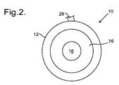
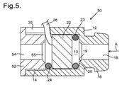
図5を参照すると、イヤホン50は、内径5.1mmの内側円筒形チャンバ13を画定する外径7.0mmの全体として円筒形のチタンケーシング12を有する。ケーシング12は、一端に、雌ねじ付き部分14を有し、ねじ山付きプラグ52がこのねじ山付き部分14に係合する。ねじ山付きプラグ52は、短いテーパ付き部分55を経て内側円筒形チャンバ13と連通した内径2.2mmの軸方向ボア54を備える。ケーシング12は、他端に、外径の小さな突出部分16を備え、この突出部分16は、短いテーパ付き部分19を経て内側円筒形チャンバ13と連通した内径2.2mmの軸方向ボア18を備える。短いテーパ付き部分55,19の各々の最も幅の広い端は、直径2.6mmである。したがって、チャンバ13の前側端部のところには内側段部20が設けられている。理解されるように、矢印Aの方向に見たイヤホン50の見た目は、図2に示されている見た目と同一である。
Referring to FIG. 5, the
円筒形チャンバ13内には、2つのOリング23,24相互間に締め付けられた音響ドライバ22が設けられ、一方のOリング23は、ドライバ22の前側フェースと内側段部20との間に位置し、他方のOリング24は、ドライバ22の後側フェースと短いテーパ付き部分55を包囲しているねじ山付きプラグ52のフェースとの間に位置する。欠くOリング23,24は、厚さが1mmであり、各Oリングは、直径3mmの中央孔を備えている。ねじ山付き部分14の長さに沿ってケーシング壁を貫通してスロット25が設けられ、ドライバ22に接続されている電気ケーブル26がOリング24に設けられた対応の隙間としての切れ目およびスロット25の端を通って突き出ている。
In the
音響ドライバ22は、ダイヤフラム(図示せず)を有し、このドライバは、ダイナミックドライバであり、すなわち、ダイヤフラムが永久磁石の磁場においてボイスコイルによって動かされる。ダイヤフラムは、有孔金属カバーによって保護された状態でドライバ22の前側フェースの近くに位置する。ダイヤフラムは、この場合、4.47mmの直径を有する。ドライバ22は、ダイヤフラムの後部周りに設けられた保護カバーを更に有し、保護カバーは、少なくとも1つの小穴を有する。理解されるように、ドライバは、異なる形式のもの、例えばバランスドアーマチュア型、扁平磁気型または静電型のものであって良く、ドライバおよびそのダイヤフラムのサイズは、本明細書において説明したサイズと異なっていても良い。
The
かくして、イヤホン50は、Oリング23を円筒形チャンバ13中に挿入し、次に電気ケーブル26がスロット25を通って突き出た状態でドライバ22を挿入することによって組み立て可能であることが理解されよう。Oリング23は、ドライバの有孔金属カバーの小穴のうちのどれも塞ぐことはない。この場合、Oリング24は、電気ケーブル26がOリング24に設けられた対応したサイズの隙間としての切れ目を通過した状態で定位置に配置され、次にねじ山付きプラグ52を定位置にきつくねじ込む。ドライバ22を2つの圧縮Oリング23,24相互間に固定的にかつしっかりと保持する。ドライバ22の後ろに位置し、すなわちドライバ22とねじ山付きプラグ52との間に位置する円筒形チャンバ13の部分内の圧力変動または音波は、軸方向ボア54を通って伝搬することができ、同じように、ドライバ22の前に位置する円筒形チャンバ13の部分内のドライバ内にドライバ22によって生じた音波は、軸方向ボア18を通ってユーザの耳の中に伝搬する。
Thus, it will be appreciated that the
Oリング23とOリング24は、非円形断面形状(図示のように軸方向断面で見て)を有しても良いことは理解されよう。例えば、これらOリングに代えてネオプレンゴムワッシャまたはガスケットを用いても良く、ただし、ワッシャまたはガスケットの半径方向幅がドライバ22のフェースの相当多くの部分を妨げるほど大きくないことを条件とし、この場合、各側の断面形状は、正方形または長方形であろう。他の材料、例えば成形シリコーンの使用もまた適している。
It will be appreciated that O-
イヤホン50の使用にあたり、突出部分16は、フォームイヤバッド、例えば形状記憶フォームイヤバッド(図示せず)を備え、この突出部分をユーザの外耳道中に挿入して軸方向ボア18がユーザの外耳道に直接結合されるようにする。ドライバ22の前側フェースから出ている音は、Oリング23の内周部によって画定される空間を通り、次に短いテーパ付き部分19を通って軸方向ボア18中に進み、この軸方向ボア18の多端部がユーザの耳に結合されている。軸方向ボア18は、明らかなこととして、イヤホン50から出た音のたどる経路の最も幅の狭いまたは細い部分であり、従って、この軸方向ボアは、絞りダクト部分として作用する。同様に、軸方向ボア54は、ドライバ22の後部から伝搬する音のための経路の最も幅の狭いまたは細い部分であり、従って絞りダクト部分として作用する。軸方向ボア54,18は、互いに整列する。と言うのは、これら軸方向ボアは両方とも円筒形チャンバ13と同軸であり、しかも同一直径のものだからである。同一直径の2つの軸方向に整列した絞りダクト部分を設けると、ドライバ22が20Hz〜20kHzの可聴範囲全体にわたって線形動作することができるので、ドライバ22の大幅に改善された周波数応答を達成することが判明した。
In use of the
上述したイヤホン10,50を種々の仕方で改造することができることは理解されよう。例えば、ケーシング12は、異なる材料、例えばアルミニウムまたは硬質の非金属材料、例えばエンジニアリングプラスチックのものであっても良い。寸法もまた与えられているが、これは例示であるに過ぎない。テーパ付き部分19の勾配および長さは、図示の勾配および長さとは異なっていても良く、段部20は、別のサイズのものであって良く、例えば、Oリング23の厚さ以下である。明らかなこととして、内側円筒形チャンバ13の直径は、ドライバ22のサイズに合うようなものでなければならず、したがって、ドライバが大型の場合、チャンバの内径もまた、それに対応して大きいであろう。
It will be appreciated that the
また、上述のイヤホン10または50に関して、Oリング23,24の厚さは、ドライバ22のフェースと内側チャンバ13の対応の端フェースとの間の距離を定めることは理解されよう。ドライバ22のフェースと内側チャンバ13の端フェースとの間に大きな距離が必要である場合、これは、より厚いOリングを使用するか、またはOリング23,24と別のリング型アイテム、例えば第2のOリングもしくは硬質材料のリングを組み合わせるかのいずれかによって達成できる。各場合において、各Oリングに代えてゴムワッシャまたはガスケットを用いることができる。
It will also be appreciated that for the
イヤホン50は、波形のゆがみを何ら生じさせないで可聴周波数範囲全体にわたって線形応答を提供することができるということが判明した。音がより正確に生じるだけでなく、長期間にわたる装用にとって快適であり、しかもユーザは、イヤホン50で一日中聞き続けた後であっても自分の耳が爽快さを感じるという報告をしていることが判明しており、すなわち、ユーザは、丸一日中の使用であっても耳の疲労感が少ないことを報告している。
It has been found that the
また、本発明は、ヘッドホンに等しく利用できることが理解されよう。この場合、ドライバおよびケーシングは、代表的には、かなり大径であり、例えば、ドライバは、直径25mm、35mmまたは50mmのものであり、ケーシングは、これよりも大きな直径、代表的には3〜6mm以上のものである。上述したように、ケーシングは、軸方向ボア54と均等である絞りダクト部分および軸方向ボア18と均等である整列状態の絞りダクト部分を備えなければならない。
It will also be appreciated that the present invention is equally applicable to headphones. In this case, the driver and casing are typically quite large in diameter, for example, the driver is of
次に図6を参照すると、かかるヘッドホン60が断面図で示されている。ヘッドホン60は、内径40.5mmの内側円筒形チャンバ33を画定する外径50mmの全体として円筒形のアルミニウムケーシング32を有する。ケーシング32は、一端のところに、雌ねじ的部分34を備え、ねじ山付きプラグ62がこのねじ山付き部分34に係合してチャンバ33のその端を塞いでいる。ケーシング32は、他端に、外部フランジ36および内部フランジ37を備えている。内部フランジ37の内側フェースは、テーパしたダクト部分39を有し、この内側フェースは、チャンバ33のその端のところに内側段部40を更に備えている。テーパしているダクト部分39は、内径17.0mmの円筒形孔またはボア38と連通している。軟質弾性材料のリング型イヤクッション42が外部フランジ36に取り付けられ、このリング型イヤクッションは、ヘッドホン60の使用中、ユーザの頭の側部に当たる。円筒形孔またはボア38は、内側円筒形チャンバ33と同軸である。
Referring now to FIG. 6, such a
ねじ山付きプラグ62は、円筒形チャンバ33中に通じるテーパ付き部分65と連通した内径17.0mmの円筒形孔またはボア64を備え、ねじ山付きプラグ62の周囲の隣に位置していてテーパ付き部分65の開口端を包囲する環状フェース66が設けられている。テーパ付き部分65は、テーパしているダクト部分39と同じ直径を有し、円筒形孔またはボア64は、円筒形孔38と整列する。
The threaded
円筒形チャンバ33内には、外径40mmの全体として平べったい円筒形の音響ドライバ44が設けられているが、この音響ドライバは、その後側フェースから突き出た円筒形磁石45を有する。これまた外径40mmの金属リング67が音響ドライバ44の後ろに位置し、Oリング68がドライバ44の後面とねじ山付きプラグ62に設けられた環状フェース66との間で圧縮されている。同様に、Oリング46は、ドライバ44の前側フェースと内側段部40との間で圧縮されている。Oリング46,68は、各々厚さが1mmであって外径が40mmであり、したがって、これらOリングは、円筒形チャンバ33の周囲に隣接して位置するようになる。この実施例では、ケーシング壁を貫通しかつドライバ44の後側フェースの後ろに位置する円筒形チャンバ33と連通した穴47が設けられ、電気ケーブル(図示せず)がドライバ44への電気的接続のためにこの穴47を通過するのが良い。
In the
Oリング46は、別個の部品であるものとして示されているが、このOリングは、変形例として、音響ドライバ44の前側フェースに設けられた突出リムを形成するものであっても良い。同様にOリング68は、別個の部品であるものとして示されているが、このOリングは、変形例として、金属リング67フェースに設けられた突出弾性リムを形成するものであっても良い。音響ドライバ44は、ダイヤフラム(図示せず)を含み、この音響ドライバは、ダイナミックドライバであり、すなわち、ダイヤフラムは、磁石45の磁場内でボイスコイルによって動かされる。ダイヤフラムは、有孔金属カバーによって保護された状態でドライバ44の前側フェースの近くに位置する。ダイヤフラムは、この場合、35mmの直径を有する。ドライバ44は、ダイヤフラムの後部の周りに設けられた保護カバーを更に有し、保護カバーは、少なくとも1つの小穴を有する。理解されるように、ドライバは、異なる形式のもの、例えばバランスドアーマチュア型、扁平磁気型、または静電型のものであって良く、ドライバおよびそのダイヤフラムのサイズは、本明細書において説明したサイズと異なっていても良い。
Although the O-
Oリング46を円筒形チャンバ33(もしこれが別個の部品であれば)中に挿入し、次にドライバ44を挿入し、そして次に電気ケーブルを穴47に通して導入して電気ケーブルをドライバ44に接続することによって、ヘッドホン60を組み立てることができる。Oリング46は、ドライバの有孔金属カバーの小穴のうちのどれも塞ぐことはない。次に、金属リング67およびOリング68を挿入し、金属リング67は、電気ケーブルを通す溝(図示せず)を備えている。次に、ねじ山付きプラグ62を挿入して締め付けてOリング46,68が圧縮されるようにする。
The O-
ヘッドホン60の使用にあたり、イヤクッション42は、音漏れを阻止し、したがって、音がユーザの耳にもたらされる。ドライバ44の前側フェースから出た音は、内部フランジ37のテーパしたダクト部分39を通らなければならず、次に円筒形孔またはボア38を通らなければならない。同様に、ドライバ44の後側フェースから出た圧力波または音は、テーパ付き部分65および円筒形孔またはボア64を通らなければならない。円筒形孔38,64は、明らかなこととして、ヘッドホン60から出た音のたどる経路の最も幅の狭いまたは細い部分であり、したがって絞りダクト部分として作用し、したがって音出力が可聴周波数範囲にわたってより一様でかつ一貫しているという上述したのと同じ利点が得られる。
In use of the
ドライバ44の前側フェースと円筒形チャンバ33の端のところの内側段部40との間の距離は、Oリング46の厚さによって定められることが理解されよう。ドライバ44の周囲の後側フェースとねじ山付きプラグ62の環状フェース66との間の距離は、これよりも幾分大きく、その理由は、この距離は、金属リム67とOリング68との組み合わせの厚さによって定められるからである。一実施形態では、金属リング67を省いても良く、そうすると、ドライバ44の周囲の後側フェースとねじ山付きプラグ62との間の距離が減少し、この改造例では、円筒形磁石45は、テーパ付き部分65中に僅かに突き出ることになる。別の改造例では、第2のリング67をOリング46に隣接して挿入するのが良く、したがって、ドライバ44の前側フェースと円筒形チャンバ33の端との間の距離が増大する。また、上述したイヤホン10,50の場合と同様、Oリング46,68に代えてゴムガスケットまたはワッシャを用いることができる。確かなこととして、Oリングが記載されている各場合において、Oリングに代えてゴムガスケットまたはワッシャ、例えばゴム代替材料、例えば成形シリコーンで作られていて例えば厚さが代表的には0.3mm〜5mm、例えば0.5mmの平ワッシャまたはガスケットを用いても良い。
It will be appreciated that the distance between the front face of the
イヤホン50とヘッドホン60の両方に関し、音質がドライバと同軸である同一直径の2つの整列した出口、すなわち、イヤホン50の軸方向ボア54,18、ヘッドホン60の円筒形孔64,38を提供することによって高められるということが判明した。これとは対照的に、例えば後側出口(すなわち、軸方向ボア54または円筒形孔64)が円筒形チャンバ13または33と同軸ではない場合、これにより、非常に不良な音質が生じる。非同軸出口によりドライバ全体にわたって非対称の圧力分布が生じ、これが音質にとって有害であることが推定される。
For both the
イヤホン10,50に関し、突出部分16は、軸方向ボア18に通じる短いテーパ付き部分19を備えた音出口ダクトを構成する。ボア18の長手方向軸線に対するテーパの角度は、好ましくは40°〜50°であり、両方のこれらの場合において、45°である。次に図7を参照すると、これは、短いテーパ付き部分19が上記において示したテーパ付き部分よりも著しく長い改造型突出部分16aを有する点においてのみケーシング12とは異なっているイヤホン70用のケーシング72の部分図であり、ただし、この場合もまた、このテーパ付き部分19は、テーパ角45°をなしている。突出部分16aの外側端部のところにおいて、軸方向ボア18は、幅広部分74中に開口し、この幅広部分74もまた、軸線に対して45°の角度をなす直線テーパを有し、その結果、軸方向ボア18は、これに対応して短い。
For the
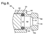
音出口ダクトは、望ましくは、テーパ付き部分を有するが、これは、円筒形部分84が設けられ、次に軸方向ボア18に通じる短いテーパ付き部分19が設けられている改造型突出部分16bを有する点においてのみケーシング12とは異なっているイヤホン80用のケーシング82の部分図であり、軸方向ボア18は、外側端部のところで、短い長手方向に湾曲したラッパ状部分86と連通している。テーパ付き部分19は、軸線に対して45°の角度をなす直線テーパを有する。音出口ダクトのこの形状は、イヤホン50に示されているプラグ52の後側出口ダクトにおいて同等に適している。
The sound outlet duct desirably has a tapered portion that includes a modified protruding
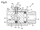
次に図9を参照すると、多くの点において、図5のイヤホン50と同一であるイヤホン90が示されており、同一の特徴は、同一の参照符号で示されている。唯一の違いは、ケーブル26のための隙間を備えたOリングシール24を提供するのではなく、これとは異なり、ケーブル26をナイロンで作られたケーブル案内92に通しているということにある。分かりやすくするために、ケーブル26は、ケーブル案内92内には示されていない。
Referring now to FIG. 9, an
図9および図10を参照すると、ケーブル案内92は、ドライバ22の後ろで円筒形キャビティ13内に同軸に嵌まり込む締め付けリング94を備え、スタッド95がこの締め付けリングから半径方向に突き出ており、スタッド95は、スロット25中に嵌まり、このスタッドは、円筒形ケーシング12の外面に装着する台形部分96を有する。入口ダクト97がスタッド95の長さ全体にわたって延びて締め付けリング94の隣接部分を貫通している。入口ダクト97内の中間位置において、左手側の壁(図9に示されている)は、突出した丸形のハンプまたはこぶ状突起98を備えている。それ故、ケーブル26は、入口ダクト97を通り、そしてリング94の中間部を貫通してドライバ22の後部に達することができ、そしてこのケーブルは、摩擦によって丸形こぶ状突起98により締め付けられる。
Referring to FIGS. 9 and 10, the
ケーブル案内92は、2つの互いに合致する部品、すなわち、入口ダクト97の一方の側部(図9に示されているような右側の側部)を構成するとともに締め付けリング94の一方のフェース(図9に示されているような右側のフェース)の弧状部分を構成するが、弧状部分の端101(これらの端のうち1つだけが図9に示されている)相互間に周方向隙間を生じさせる第1の部品100および入口ダクト97の他方の側部を構成するとともに更に端101相互間の周方向隙間内に嵌まり込む突出部分103を含む締め付けリング94の残部を構成する第2の部品102を含む。2つの部品100,102を互いに合わせると、それ故、締め付けリング94は、実質的に連続した前側フェースおよび実質的に連続した後側フェースを有する。
The
それ故、組み立ての際、ケーブル26内の電線をドライバ22の後部に設けられている端子にはんだ付けするのが良い。次に、ケーブル26をケーブル案内92の第1の部品100によって構成された入口ダクト97の右側(図9に示されている)中に布設し、したがって、弧状部分の2つの端101がケーブル26の互いに反対側の側部で突き出る。次に、ケーブル案内92の第2の部品102を第1の部品100と合わせ、したがって、突出部分103が弧状部分の2つの端101相互間に嵌まって締め付けリング94の右側フェース(図9に示されている)を完成させ、次に、ケーブル26を突出こぶ状突起によって押しつぶすとともに締め付ける。次に、ねじ山付きプラグ52をねじ山付き部分14中にねじ込んで締め付けリング94がプラグ52の前側フェースとドライバ22の後側フェースとの間で圧縮する。締め付けリング94は、ドライバ22の後側フェースの周囲全体に沿ってぐるりと実質的に一様な圧縮状態をもたらす。さらに、ケーブル26を入口ダクト97内でこぶ状突起98によって締め付け、その結果、ケーブル26に加わる張力がケーブル案内92を通ってイヤホン90に伝えられ、その結果、ケーブル26内の電線とドライバ22の端子との間の接続部またははんだ継手が張力を受けないようにする。
Therefore, at the time of assembly, it is preferable to solder the electric wire in the
Claims (14)
Applications Claiming Priority (5)
| Application Number | Priority Date | Filing Date | Title |
|---|---|---|---|
| GB1506111.2 | 2015-04-10 | ||
| GBGB1506111.2A GB201506111D0 (en) | 2015-04-10 | 2015-04-10 | Headphone or earphone |
| GB1518586.1 | 2015-10-20 | ||
| GBGB1518586.1A GB201518586D0 (en) | 2015-10-20 | 2015-10-20 | Headphone or earphone |
| PCT/GB2016/050981 WO2016162681A1 (en) | 2015-04-10 | 2016-04-07 | Headphone or earphone |
Publications (2)
| Publication Number | Publication Date |
|---|---|
| JP2018511273A true JP2018511273A (en) | 2018-04-19 |
| JP2018511273A5 JP2018511273A5 (en) | 2019-05-16 |
Family
ID=55754326
Family Applications (1)
| Application Number | Title | Priority Date | Filing Date |
|---|---|---|---|
| JP2017552986A Ceased JP2018511273A (en) | 2015-04-10 | 2016-04-07 | Headphone or earphone |
Country Status (6)
| Country | Link |
|---|---|
| US (1) | US11343606B2 (en) |
| EP (1) | EP3281415B1 (en) |
| JP (1) | JP2018511273A (en) |
| KR (1) | KR20170134703A (en) |
| CN (1) | CN107873134B (en) |
| WO (1) | WO2016162681A1 (en) |
Families Citing this family (4)
| Publication number | Priority date | Publication date | Assignee | Title |
|---|---|---|---|---|
| GB2559313A (en) * | 2016-11-11 | 2018-08-08 | Flare Audio Tech Limited | Earphone |
| US10491975B2 (en) * | 2017-10-20 | 2019-11-26 | Bose Corporation | Acoustic transducer system |
| EP3742753B1 (en) | 2019-05-24 | 2021-12-01 | Honeywell International Inc. | Hearing protection devices, noise exposure sensors therefor, and sensor housings and associated methods for the same |
| US11245972B2 (en) | 2019-12-06 | 2022-02-08 | Steven Hill | Ear tip device |
Citations (5)
| Publication number | Priority date | Publication date | Assignee | Title |
|---|---|---|---|---|
| JPS63200988U (en) * | 1987-06-15 | 1988-12-23 | ||
| JP2006246426A (en) * | 2005-06-15 | 2006-09-14 | Kazuo Suzuki | Earphone attachment and earphone equipped with the earphone attachment |
| JP2010516096A (en) * | 2007-01-06 | 2010-05-13 | アップル インコーポレイテッド | Headset connector that selectively transfers signals according to the specific direction of the engaging connector |
| JP2011082701A (en) * | 2009-10-05 | 2011-04-21 | Foster Electric Co Ltd | Headphone |
| JP3196121U (en) * | 2014-12-10 | 2015-02-19 | 勁剛企業有限公司 | Earphone with vent |
Family Cites Families (25)
| Publication number | Priority date | Publication date | Assignee | Title |
|---|---|---|---|---|
| US5682434A (en) * | 1995-06-07 | 1997-10-28 | Interval Research Corporation | Wearable audio system with enhanced performance |
| JP4151157B2 (en) | 1999-05-31 | 2008-09-17 | ソニー株式会社 | earphone |
| JP4709017B2 (en) * | 2006-01-12 | 2011-06-22 | ソニー株式会社 | Earphone device |
| US8712071B2 (en) | 2007-01-05 | 2014-04-29 | Apple Inc. | Headset electronics |
| JP4921197B2 (en) * | 2007-02-06 | 2012-04-25 | スター精密株式会社 | Insertion type earphone |
| US8194911B2 (en) | 2007-03-27 | 2012-06-05 | Logitech International, S.A. | Earphone integrated eartip |
| JP4823362B2 (en) * | 2007-09-07 | 2011-11-24 | パイオニア株式会社 | earphone |
| CN102006533B (en) | 2009-08-31 | 2014-08-27 | 富准精密工业(深圳)有限公司 | Earphone |
| EP2306755B1 (en) * | 2009-09-03 | 2015-06-03 | AKG Acoustics GmbH | In-ear earphone |
| TWI435618B (en) * | 2009-10-05 | 2014-04-21 | Merry Electronics Co Ltd | Earphone device with bass adjustment function |
| JP5666797B2 (en) * | 2009-10-05 | 2015-02-12 | フォスター電機株式会社 | earphone |
| US20120314882A1 (en) | 2009-11-23 | 2012-12-13 | Incus Laboratories Limited | Production of ambient noise-cancelling earphones |
| JP5671929B2 (en) | 2010-10-12 | 2015-02-18 | ソニー株式会社 | Earphone, acoustic converter |
| CN202035122U (en) * | 2011-01-21 | 2011-11-09 | 东莞达电电子有限公司 | Earphone with live effect |
| EP2811757B1 (en) | 2012-01-30 | 2016-05-25 | Panasonic Intellectual Property Management Co., Ltd. | Earphone |
| CN202773055U (en) * | 2012-07-31 | 2013-03-06 | 东莞达电电子有限公司 | Earphone facilitating adjustment of sound effect |
| KR101423881B1 (en) * | 2013-05-24 | 2014-07-25 | 부전전자 주식회사 | Micro Speaker Unit for Earphone |
| KR101558091B1 (en) | 2014-05-23 | 2015-10-06 | 부전전자 주식회사 | Canal type earphone with pressure equilibrium means |
| US8983108B2 (en) | 2013-07-18 | 2015-03-17 | Dexin Corporation | Ear headphone |
| US9363594B2 (en) | 2013-12-13 | 2016-06-07 | Apple Inc. | Earbud with membrane based acoustic mass loading |
| CN203661262U (en) | 2014-01-02 | 2014-06-18 | 东莞市伟旺达电子有限公司 | Dustproof earphone |
| CN104936080A (en) * | 2015-07-07 | 2015-09-23 | 常州百富电子有限公司 | Earplug with silencing plug post |
| US9794676B2 (en) * | 2016-01-12 | 2017-10-17 | Bose Corporation | Headphone |
| TWI628961B (en) * | 2016-11-24 | 2018-07-01 | 王士俊 | Earphone for regulating pressure in ear canal and providing natural sound and manufacture method thereof |
| CN110944266B (en) * | 2019-12-13 | 2021-07-06 | 多摩电子(东莞)有限公司 | Flexible in-ear type dustproof earphone based on spring is spacing |
-
2016
- 2016-04-07 JP JP2017552986A patent/JP2018511273A/en not_active Ceased
- 2016-04-07 WO PCT/GB2016/050981 patent/WO2016162681A1/en active Application Filing
- 2016-04-07 CN CN201680033719.2A patent/CN107873134B/en active Active
- 2016-04-07 KR KR1020177032213A patent/KR20170134703A/en unknown
- 2016-04-07 US US15/562,368 patent/US11343606B2/en active Active
- 2016-04-07 EP EP16716651.1A patent/EP3281415B1/en active Active
Patent Citations (5)
| Publication number | Priority date | Publication date | Assignee | Title |
|---|---|---|---|---|
| JPS63200988U (en) * | 1987-06-15 | 1988-12-23 | ||
| JP2006246426A (en) * | 2005-06-15 | 2006-09-14 | Kazuo Suzuki | Earphone attachment and earphone equipped with the earphone attachment |
| JP2010516096A (en) * | 2007-01-06 | 2010-05-13 | アップル インコーポレイテッド | Headset connector that selectively transfers signals according to the specific direction of the engaging connector |
| JP2011082701A (en) * | 2009-10-05 | 2011-04-21 | Foster Electric Co Ltd | Headphone |
| JP3196121U (en) * | 2014-12-10 | 2015-02-19 | 勁剛企業有限公司 | Earphone with vent |
Also Published As
| Publication number | Publication date |
|---|---|
| CN107873134A (en) | 2018-04-03 |
| KR20170134703A (en) | 2017-12-06 |
| WO2016162681A1 (en) | 2016-10-13 |
| EP3281415B1 (en) | 2019-06-12 |
| EP3281415A1 (en) | 2018-02-14 |
| US11343606B2 (en) | 2022-05-24 |
| US20180288520A1 (en) | 2018-10-04 |
| CN107873134B (en) | 2019-08-27 |
Similar Documents
| Publication | Publication Date | Title |
|---|---|---|
| JP6475844B2 (en) | Open headphones | |
| US11146876B2 (en) | Kernel-type earphone having pressure balance structure | |
| US8311259B2 (en) | In-ear earphone | |
| US6775390B1 (en) | Headset with movable earphones | |
| US20120243726A1 (en) | Earphone | |
| JP2018511273A (en) | Headphone or earphone | |
| JP6621166B1 (en) | Earpiece and earphone using the same | |
| JPWO2009031238A1 (en) | earphone | |
| JP2019145962A (en) | earphone | |
| JP2012257049A (en) | Audio output device | |
| JP6754075B2 (en) | earphone | |
| KR101310879B1 (en) | Earphone | |
| US9544676B2 (en) | Oval shaped in-ear headphone | |
| JP3161011U (en) | Earpiece and headphones using the same | |
| EP3200476B1 (en) | Headphone | |
| JP2011049686A (en) | Earphone | |
| US20160173969A1 (en) | Multiple position earphone cable exit | |
| KR102020330B1 (en) | Earphone assembly | |
| JP6863687B2 (en) | earphone | |
| JP2019145963A (en) | earphone | |
| JP2019145965A (en) | earphone | |
| CN106454591B (en) | Earphone set | |
| WO2020148819A1 (en) | Intra-concha earphones | |
| WO2024085250A1 (en) | Open-type earphone | |
| US20230048436A1 (en) | Earphone |
Legal Events
| Date | Code | Title | Description |
|---|---|---|---|
| A524 | Written submission of copy of amendment under article 19 pct |
Free format text: JAPANESE INTERMEDIATE CODE: A524 Effective date: 20190405 |
|
| A621 | Written request for application examination |
Free format text: JAPANESE INTERMEDIATE CODE: A621 Effective date: 20190405 |
|
| A977 | Report on retrieval |
Free format text: JAPANESE INTERMEDIATE CODE: A971007 Effective date: 20200424 |
|
| A01 | Written decision to grant a patent or to grant a registration (utility model) |
Free format text: JAPANESE INTERMEDIATE CODE: A01 Effective date: 20200518 |
|
| A045 | Written measure of dismissal of application [lapsed due to lack of payment] |
Free format text: JAPANESE INTERMEDIATE CODE: A045 Effective date: 20200923 |