JP2018509799A - Method and apparatus for distortion-free display of the vehicle periphery of a vehicle - Google Patents
Method and apparatus for distortion-free display of the vehicle periphery of a vehicle Download PDFInfo
- Publication number
- JP2018509799A JP2018509799A JP2017538401A JP2017538401A JP2018509799A JP 2018509799 A JP2018509799 A JP 2018509799A JP 2017538401 A JP2017538401 A JP 2017538401A JP 2017538401 A JP2017538401 A JP 2017538401A JP 2018509799 A JP2018509799 A JP 2018509799A
- Authority
- JP
- Japan
- Prior art keywords
- vehicle
- camera
- data
- surround view
- projection plane
- Prior art date
- Legal status (The legal status is an assumption and is not a legal conclusion. Google has not performed a legal analysis and makes no representation as to the accuracy of the status listed.)
- Pending
Links
- 238000000034 method Methods 0.000 title claims description 19
- 230000003044 adaptive effect Effects 0.000 claims abstract description 16
- 230000002093 peripheral effect Effects 0.000 claims abstract description 12
- 240000004050 Pentaglottis sempervirens Species 0.000 claims description 3
- 235000004522 Pentaglottis sempervirens Nutrition 0.000 claims description 3
- 238000004590 computer program Methods 0.000 claims description 2
- 230000003068 static effect Effects 0.000 description 6
- 238000004364 calculation method Methods 0.000 description 2
- 238000013500 data storage Methods 0.000 description 1
- 230000001419 dependent effect Effects 0.000 description 1
- 238000010586 diagram Methods 0.000 description 1
- 238000005192 partition Methods 0.000 description 1
- 238000000547 structure data Methods 0.000 description 1
Images

Classifications
-
- B—PERFORMING OPERATIONS; TRANSPORTING
- B60—VEHICLES IN GENERAL
- B60R—VEHICLES, VEHICLE FITTINGS, OR VEHICLE PARTS, NOT OTHERWISE PROVIDED FOR
- B60R1/00—Optical viewing arrangements; Real-time viewing arrangements for drivers or passengers using optical image capturing systems, e.g. cameras or video systems specially adapted for use in or on vehicles
- B60R1/20—Real-time viewing arrangements for drivers or passengers using optical image capturing systems, e.g. cameras or video systems specially adapted for use in or on vehicles
- B60R1/22—Real-time viewing arrangements for drivers or passengers using optical image capturing systems, e.g. cameras or video systems specially adapted for use in or on vehicles for viewing an area outside the vehicle, e.g. the exterior of the vehicle
- B60R1/23—Real-time viewing arrangements for drivers or passengers using optical image capturing systems, e.g. cameras or video systems specially adapted for use in or on vehicles for viewing an area outside the vehicle, e.g. the exterior of the vehicle with a predetermined field of view
- B60R1/27—Real-time viewing arrangements for drivers or passengers using optical image capturing systems, e.g. cameras or video systems specially adapted for use in or on vehicles for viewing an area outside the vehicle, e.g. the exterior of the vehicle with a predetermined field of view providing all-round vision, e.g. using omnidirectional cameras
-
- B—PERFORMING OPERATIONS; TRANSPORTING
- B60—VEHICLES IN GENERAL
- B60R—VEHICLES, VEHICLE FITTINGS, OR VEHICLE PARTS, NOT OTHERWISE PROVIDED FOR
- B60R1/00—Optical viewing arrangements; Real-time viewing arrangements for drivers or passengers using optical image capturing systems, e.g. cameras or video systems specially adapted for use in or on vehicles
- B60R1/20—Real-time viewing arrangements for drivers or passengers using optical image capturing systems, e.g. cameras or video systems specially adapted for use in or on vehicles
- B60R1/22—Real-time viewing arrangements for drivers or passengers using optical image capturing systems, e.g. cameras or video systems specially adapted for use in or on vehicles for viewing an area outside the vehicle, e.g. the exterior of the vehicle
- B60R1/28—Real-time viewing arrangements for drivers or passengers using optical image capturing systems, e.g. cameras or video systems specially adapted for use in or on vehicles for viewing an area outside the vehicle, e.g. the exterior of the vehicle with an adjustable field of view
-
- B—PERFORMING OPERATIONS; TRANSPORTING
- B60—VEHICLES IN GENERAL
- B60W—CONJOINT CONTROL OF VEHICLE SUB-UNITS OF DIFFERENT TYPE OR DIFFERENT FUNCTION; CONTROL SYSTEMS SPECIALLY ADAPTED FOR HYBRID VEHICLES; ROAD VEHICLE DRIVE CONTROL SYSTEMS FOR PURPOSES NOT RELATED TO THE CONTROL OF A PARTICULAR SUB-UNIT
- B60W40/00—Estimation or calculation of non-directly measurable driving parameters for road vehicle drive control systems not related to the control of a particular sub unit, e.g. by using mathematical models
- B60W40/02—Estimation or calculation of non-directly measurable driving parameters for road vehicle drive control systems not related to the control of a particular sub unit, e.g. by using mathematical models related to ambient conditions
-
- B—PERFORMING OPERATIONS; TRANSPORTING
- B60—VEHICLES IN GENERAL
- B60W—CONJOINT CONTROL OF VEHICLE SUB-UNITS OF DIFFERENT TYPE OR DIFFERENT FUNCTION; CONTROL SYSTEMS SPECIALLY ADAPTED FOR HYBRID VEHICLES; ROAD VEHICLE DRIVE CONTROL SYSTEMS FOR PURPOSES NOT RELATED TO THE CONTROL OF A PARTICULAR SUB-UNIT
- B60W50/00—Details of control systems for road vehicle drive control not related to the control of a particular sub-unit, e.g. process diagnostic or vehicle driver interfaces
- B60W50/08—Interaction between the driver and the control system
- B60W50/14—Means for informing the driver, warning the driver or prompting a driver intervention
-
- G—PHYSICS
- G06—COMPUTING; CALCULATING OR COUNTING
- G06V—IMAGE OR VIDEO RECOGNITION OR UNDERSTANDING
- G06V20/00—Scenes; Scene-specific elements
- G06V20/50—Context or environment of the image
- G06V20/56—Context or environment of the image exterior to a vehicle by using sensors mounted on the vehicle
- G06V20/58—Recognition of moving objects or obstacles, e.g. vehicles or pedestrians; Recognition of traffic objects, e.g. traffic signs, traffic lights or roads
-
- H—ELECTRICITY
- H04—ELECTRIC COMMUNICATION TECHNIQUE
- H04N—PICTORIAL COMMUNICATION, e.g. TELEVISION
- H04N7/00—Television systems
- H04N7/18—Closed-circuit television [CCTV] systems, i.e. systems in which the video signal is not broadcast
- H04N7/181—Closed-circuit television [CCTV] systems, i.e. systems in which the video signal is not broadcast for receiving images from a plurality of remote sources
-
- B—PERFORMING OPERATIONS; TRANSPORTING
- B60—VEHICLES IN GENERAL
- B60R—VEHICLES, VEHICLE FITTINGS, OR VEHICLE PARTS, NOT OTHERWISE PROVIDED FOR
- B60R2300/00—Details of viewing arrangements using cameras and displays, specially adapted for use in a vehicle
- B60R2300/10—Details of viewing arrangements using cameras and displays, specially adapted for use in a vehicle characterised by the type of camera system used
- B60R2300/101—Details of viewing arrangements using cameras and displays, specially adapted for use in a vehicle characterised by the type of camera system used using cameras with adjustable capturing direction
-
- B—PERFORMING OPERATIONS; TRANSPORTING
- B60—VEHICLES IN GENERAL
- B60R—VEHICLES, VEHICLE FITTINGS, OR VEHICLE PARTS, NOT OTHERWISE PROVIDED FOR
- B60R2300/00—Details of viewing arrangements using cameras and displays, specially adapted for use in a vehicle
- B60R2300/30—Details of viewing arrangements using cameras and displays, specially adapted for use in a vehicle characterised by the type of image processing
- B60R2300/301—Details of viewing arrangements using cameras and displays, specially adapted for use in a vehicle characterised by the type of image processing combining image information with other obstacle sensor information, e.g. using RADAR/LIDAR/SONAR sensors for estimating risk of collision
-
- B—PERFORMING OPERATIONS; TRANSPORTING
- B60—VEHICLES IN GENERAL
- B60R—VEHICLES, VEHICLE FITTINGS, OR VEHICLE PARTS, NOT OTHERWISE PROVIDED FOR
- B60R2300/00—Details of viewing arrangements using cameras and displays, specially adapted for use in a vehicle
- B60R2300/30—Details of viewing arrangements using cameras and displays, specially adapted for use in a vehicle characterised by the type of image processing
- B60R2300/306—Details of viewing arrangements using cameras and displays, specially adapted for use in a vehicle characterised by the type of image processing using a re-scaling of images
-
- B—PERFORMING OPERATIONS; TRANSPORTING
- B60—VEHICLES IN GENERAL
- B60R—VEHICLES, VEHICLE FITTINGS, OR VEHICLE PARTS, NOT OTHERWISE PROVIDED FOR
- B60R2300/00—Details of viewing arrangements using cameras and displays, specially adapted for use in a vehicle
- B60R2300/30—Details of viewing arrangements using cameras and displays, specially adapted for use in a vehicle characterised by the type of image processing
- B60R2300/307—Details of viewing arrangements using cameras and displays, specially adapted for use in a vehicle characterised by the type of image processing virtually distinguishing relevant parts of a scene from the background of the scene
-
- B—PERFORMING OPERATIONS; TRANSPORTING
- B60—VEHICLES IN GENERAL
- B60R—VEHICLES, VEHICLE FITTINGS, OR VEHICLE PARTS, NOT OTHERWISE PROVIDED FOR
- B60R2300/00—Details of viewing arrangements using cameras and displays, specially adapted for use in a vehicle
- B60R2300/60—Details of viewing arrangements using cameras and displays, specially adapted for use in a vehicle characterised by monitoring and displaying vehicle exterior scenes from a transformed perspective
- B60R2300/602—Details of viewing arrangements using cameras and displays, specially adapted for use in a vehicle characterised by monitoring and displaying vehicle exterior scenes from a transformed perspective with an adjustable viewpoint
-
- B—PERFORMING OPERATIONS; TRANSPORTING
- B60—VEHICLES IN GENERAL
- B60R—VEHICLES, VEHICLE FITTINGS, OR VEHICLE PARTS, NOT OTHERWISE PROVIDED FOR
- B60R2300/00—Details of viewing arrangements using cameras and displays, specially adapted for use in a vehicle
- B60R2300/60—Details of viewing arrangements using cameras and displays, specially adapted for use in a vehicle characterised by monitoring and displaying vehicle exterior scenes from a transformed perspective
- B60R2300/607—Details of viewing arrangements using cameras and displays, specially adapted for use in a vehicle characterised by monitoring and displaying vehicle exterior scenes from a transformed perspective from a bird's eye viewpoint
-
- B—PERFORMING OPERATIONS; TRANSPORTING
- B60—VEHICLES IN GENERAL
- B60W—CONJOINT CONTROL OF VEHICLE SUB-UNITS OF DIFFERENT TYPE OR DIFFERENT FUNCTION; CONTROL SYSTEMS SPECIALLY ADAPTED FOR HYBRID VEHICLES; ROAD VEHICLE DRIVE CONTROL SYSTEMS FOR PURPOSES NOT RELATED TO THE CONTROL OF A PARTICULAR SUB-UNIT
- B60W2420/00—Indexing codes relating to the type of sensors based on the principle of their operation
- B60W2420/40—Photo or light sensitive means, e.g. infrared sensors
- B60W2420/403—Image sensing, e.g. optical camera
-
- B60W2420/408—
Landscapes
- Engineering & Computer Science (AREA)
- Multimedia (AREA)
- Mechanical Engineering (AREA)
- Signal Processing (AREA)
- Automation & Control Theory (AREA)
- Transportation (AREA)
- Physics & Mathematics (AREA)
- Human Computer Interaction (AREA)
- Mathematical Physics (AREA)
- General Physics & Mathematics (AREA)
- Theoretical Computer Science (AREA)
- Closed-Circuit Television Systems (AREA)
- Traffic Control Systems (AREA)
Abstract
データ処理ユニットによって、表示ユニット上に表示されるサラウンド・ビュー画像乃至周辺画像を作成するために、処理されるカメラ画像を提供する少なくとも一台の車載カメラを有する、但し、該データ処理ユニットが、車載カメラによって捕捉されたテクスチャーを、車載センサー類によって提供されたセンサーデータをベースに算出されるアダプティブな車両周辺部に近似した再・投影面に再・投影する、但し、該データ処理ユニットが、該バーチャルカメラのポジションとオリエンテーションに基づいて再・投影面を調節することを特徴とする車両用のカメラ・サラウンド・ビュー・システムに関する。The data processing unit has at least one in-vehicle camera that provides a camera image to be processed in order to create a surround view image or a peripheral image displayed on the display unit, provided that the data processing unit comprises: The texture captured by the in-vehicle camera is re-projected onto a re-projection surface that approximates the adaptive vehicle periphery calculated based on the sensor data provided by the in-vehicle sensors, provided that the data processing unit The present invention relates to a camera surround view system for a vehicle that adjusts the re-projection plane based on the position and orientation of the virtual camera.
Description
本発明は、車両の、特に、カメラ・サラウンド・ビュー・システムを装備した道路交通用車両の車両周辺部の歪無い表示を可能にする方法、並びに、装置に関する。 The present invention relates to a method and an apparatus that enable a distortion-free display of the vehicle periphery, in particular the vehicle periphery of a road traffic vehicle equipped with a camera surround view system.
車両には、運転手を運転マヌーバの実施においてサポートするドライバー・アシスタント・システムが、ますます、装備されるようになってきている。ドライバー・アシスタント・システムの一部は、車両の車両周辺部を、該車両のドライバーに表示することを可能にするカメラ・サラウンド・ビュー・システムを包含している。この様なカメラ・サラウンド・ビュー・システムは、該カメラ・サラウンド・ビュー・システムのデータ処理ユニットによって、車両周辺部の周辺画像に統合されるカメラ画像を供給する一台の、或いは、複数台の車載カメラを包含している。そしてこの車両周辺部の画像は、表示ユニット上に表示される。従来のカメラベースのドライバー・アシスタント・システムは、カメラ・システムのテクスチャー情報を静的な投影面、例えば、静的な二次元の基準面、或いは、静的な三次元の凹面に投影する。 Vehicles are increasingly equipped with driver assistance systems that support drivers in the implementation of driving maneuvers. Part of the driver assistance system includes a camera surround view system that allows the vehicle periphery of the vehicle to be displayed to the driver of the vehicle. In such a camera surround view system, one or a plurality of camera surround views are supplied by a data processing unit of the camera surround view system. In-vehicle camera is included. And the image of this vehicle peripheral part is displayed on a display unit. Conventional camera-based driver assistant systems project camera system texture information onto a static projection surface, such as a static two-dimensional reference surface or a static three-dimensional concave surface.
しかしこのようなシステムには、テクスチャー・再・投影面が静的であり、それが故に、カメラ・システムの実際の周辺部に対応していない、乃至、近似していないため、車両周辺部のオブジェクトが、極度に歪んで表示されると言う致命的な欠点がある。即ち、邪魔なアーティファクトとなる極度に歪んだオブジェクトが表示される。 However, in such a system, the texture, re-projection plane is static and therefore does not correspond to or approximate the actual periphery of the camera system. There is a fatal drawback that objects are displayed with extreme distortion. That is, an extremely distorted object that is a disturbing artifact is displayed.
よって、本発明の課題は、車両周辺部の障害物を可能な限り良好に示し、歪みなく描写するために、このような歪んだアーティファクトの表示を抑えることのできる、車両周辺部の歪無い表示を可能にする装置、並びに、方法を提供することにある。 Therefore, an object of the present invention is to display the vehicle peripheral portion without distortion, which can suppress the display of such a distorted artifact in order to show the obstacle around the vehicle as well as possible and depict it without distortion. It is an object of the present invention to provide an apparatus and a method that enable the above.
この課題は、本発明の請求項1記載の特徴を有するカメラ・サラウンド・ビュー・システムによって達成される。
This object is achieved by a camera surround view system having the features of
即ち、本発明は、その第一のアスペクトにおいて車両用のカメラ・サラウンド・ビュー・システムを提供するが、ここでは、該カメラ・サラウンド・ビュー・システムは、表示ユニット上に表示されるサラウンド・ビュー画像乃至周辺画像を作成するために、データ処理ユニットによって処理されるカメラ画像を供給する少なくとも一台の車載カメラを有しており、該データ処理ユニットは、車載カメラによって捕捉されたテクスチャーを、該車両の車載センサー類によって提供されたセンサーデータをベースに算出されるアダプティブな車両周辺部に近似した再・投影面に再・投影するとともに、該データ処理ユニットは、バーチャルカメラの位置、及び/或いは、向きに応じて該再・投影面を調節している。 That is, the present invention in its first aspect provides a camera surround view system for a vehicle, wherein the camera surround view system is a surround view displayed on a display unit. In order to create an image or a peripheral image, it has at least one in-vehicle camera that supplies a camera image processed by the data processing unit, and the data processing unit converts the texture captured by the in-vehicle camera into the texture. Re-projecting onto a re-projection plane that approximates an adaptive vehicle periphery calculated based on sensor data provided by the in-vehicle sensors of the vehicle, and the data processing unit includes the position of the virtual camera, and / or The re-projection plane is adjusted according to the direction.
本発明に係るカメラ・サラウンド・ビュー・システムのある可及的実施形態においては、車載センサー類によって提供されたセンサーデータが、車両の車両周辺部を正確に描写している。 In one possible embodiment of the camera surround view system according to the present invention, the sensor data provided by the in-vehicle sensors accurately depicts the vehicle periphery of the vehicle.
本発明に係るカメラ・サラウンド・ビュー・システムの更なる可及的実施形態においては、センサーデータは、駐車間隔データ、レーダーデータ、ライダーデータ、カメラデータ、レーザー・スキャンデータ、及び/或いは、動きに関するデータが包含される。 In a further possible embodiment of the camera surround view system according to the invention, the sensor data relates to parking distance data, radar data, rider data, camera data, laser scan data and / or movement. Data is included.
本発明に係るカメラ・サラウンド・ビュー・システムの更なる可及的実施形態においては、アダプティブな再・投影面が、動的に可変なグリッドを有している。 In a further possible embodiment of the camera surround view system according to the invention, the adaptive re-projection plane has a dynamically variable grid.
本発明に係るカメラ・サラウンド・ビュー・システム更なる可及的実施形態においては、再・投影面のグリッドが、提供されたセンサーデータに応じて動的に可変である。 In a further possible embodiment of the camera surround view system according to the invention, the grid of the re-projection plane is dynamically variable depending on the sensor data provided.
本発明に係るカメラ・サラウンド・ビュー・システム更なる可及的実施形態においては、再・投影面のグリッドが、三次元グリッドである。 In a further possible embodiment of the camera surround view system according to the invention, the grid of the re-projection plane is a three-dimensional grid.
本発明に係るカメラ・サラウンド・ビュー・システムのある可及的実施形態においては、表示ユニットは、タッチスクリーンであり、バーチャルカメラのポジション及び/或いは方向を、ユーザーが、該タッチスクリーンを用いて設定できるようになっている。 In a possible embodiment of the camera surround view system according to the present invention, the display unit is a touch screen, and the position and / or direction of the virtual camera is set by the user using the touch screen. It can be done.
本発明は、更に、特許請求項7に記載の特徴を有する車両用のドライバー・アシスタント・システムも実現する。 The invention also realizes a driver assistance system for a vehicle having the features of claim 7.
即ち、本発明は、その第二のアスペクトにおいてカメラ・サラウンド・ビュー・システムを内蔵したドライバー・アシスタント・システムを提供するが、該システムは、少なくとも一台の車載カメラを有しており、該車載カメラは、表示ユニット上に表示されるサラウンド・ビュー画像を作成するために、データ処理ユニットによって処理されるカメラ画像を供給するが、該データ処理ユニットは、該車両の車載カメラによって捕捉されたテクスチャーを、車載センサー類によって提供されたセンサーデータをベースに算出されるアダプティブな車両周辺部に近似した再・投影面に再・投影される。 That is, the present invention provides a driver assistant system incorporating a camera surround view system in the second aspect, and the system has at least one in-vehicle camera, The camera supplies a camera image that is processed by a data processing unit to create a surround view image that is displayed on the display unit, the data processing unit receiving the texture captured by the vehicle's in-vehicle camera. Is re-projected onto a re-projection surface that approximates an adaptive vehicle periphery calculated based on sensor data provided by the in-vehicle sensors.
本発明は、更に、特許請求項8に記載の特徴を有する車両の車両周辺部の歪みない表示を得るための方法を実現する。 The invention further realizes a method for obtaining an undistorted display of the vehicle periphery of a vehicle having the features of claim 8.
即ち、本発明は、以下のステップを有する車両の車両周辺部の歪みない表示を得るための方法を実現する:
車両の車載カメラによって車両周辺部のカメラ画像を作成するステップ、
作成されたカメラ画像を車両周辺部の周辺画像を作成するために処理するステップ、
車載カメラによって捕捉されたテクスチャーを、車載センサー類によって提供されたセンサーデータをベースに算出されたアダプティブな車両周辺部に近似した再・投影面に再・投影するステップ、並びに、
車両の鳥瞰図的カメラ画像を供給するバーチャルカメラの位置、及び/或いは、向きに応じて該再・投影面を調整するステップ。
That is, the present invention realizes a method for obtaining an undistorted display of the vehicle periphery of a vehicle having the following steps:
Creating a camera image of the vehicle periphery by an in-vehicle camera of the vehicle;
Processing the created camera image to create a surrounding image of the vehicle periphery;
Re-projecting the texture captured by the in-vehicle camera onto a re-projection plane that approximates the adaptive vehicle periphery calculated based on the sensor data provided by the in-vehicle sensors; and
Adjusting the re-projection plane according to the position and / or orientation of a virtual camera that supplies a bird's-eye view camera image of the vehicle;
本発明に係る方法の更なる可及的実施形態は、従属請求項に記載されている。 Further possible embodiments of the method according to the invention are described in the dependent claims.
以下、車両の車両周辺部の歪みない表示を得るための本発明に係る装置、並びに、本発明に係る方法の可及的実施形態を、添付されている図を用いて詳細に説明する。 DESCRIPTION OF THE PREFERRED EMBODIMENTS Hereinafter, possible embodiments of an apparatus according to the present invention and a method according to the present invention for obtaining an undistorted display of a vehicle periphery will be described in detail with reference to the accompanying drawings.
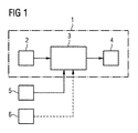
図1からも明らかなように、示されている例では、カメラ・サラウンド・ビュー・システム1は、多数のコンポーネントを有している。該カメラ・サラウンド・ビュー・システム1は、示されている実施例では、少なくとも一台の、該カメラ・サラウンド・ビュー・システム1のデータ処理ユニット3によって該車両のサラウンド・ビュー画像、乃至、周辺画像に加工されるカメラ画像を供給する車載カメラ2を有している。該データ処理ユニット3によって作成されたサラウンド・ビュー画像、乃至、車両周辺画像は、表示手段4上に表示される。データ処理ユニット3は、車両の車載センサー類5によって提供さえるセンサーデータをベースに、アダプティブな再・投影面を算出する。カメラ・サラウンド・ビュー・システム1の車載カメラ2によって捕捉されたテクスチャーは、この算出されたアダプティブな車両周辺部に近似する再・投影面に再・投影され、これにより、歪みやアーティファクトは、最小限に抑えられる、乃至、除去される。
As is apparent from FIG. 1, in the example shown, the camera
図1に示されているセンサー類5は、例えば、駐車間隔制御用、乃至、駐車間隔帰還制御用のセンサー類である。車両のこれらのセンサー類としては更に、レーダーセンサー、ライダーセンサーなども挙げられる。更なる可及的実施形態においては、更なる車載カメラ2、特に好ましくは、ステレオ・カメラ、或いは、モノカメラからセンサーデータが、アダプティブな再・投影面の計算のために供給される。更なる可及的実施形態においては、車両のレーザー・スキャン・システムからセンサーデータが供給される。更なる可及的実施形態においては、動きに関するデータ、或いは、ストラクチャー・データも、データ処理ユニット3による再・投影面の計算のために用いられる。車載センサー5から提供されたセンサーデータは、高い精度をもって、車両周辺部、乃至、車両周辺部のオブジェクトを再現する。ここで言うオブジェクトとは、例えば、車両の周辺部の極近傍、例えば、半径五メートル以内にある他の車両のことである。該オブジェクトとして更には、半径五メートル以内の極近傍にいる歩行者も挙げられる。該オブジェクトは、その他の、駐車場の駐車スペース区画用のポールなどの障害物であることもできる。
The sensors 5 shown in FIG. 1 are, for example, sensors for parking interval control or parking interval feedback control. Further examples of these sensors of the vehicle include a radar sensor and a rider sensor. In a further possible embodiment, sensor data from a further in-
該データ処理ユニット3によってセンサーデータをベースに計算された再・投影面は、好ましくは、動的に可変なグリッド、乃至、メッシュを有している。この再・投影面のグリッドは、ある可及的実施形態においては、提供されるセンサーデータに基づいて動的に変更される。尚、該再・投影面のグリッドは、好ましくは、三次元のグリッドである。データ処理ユニット3により計算された再・投影面は、静的ではなく、動的であり、車載センサー類5から供給されるその時点のセンサーデータに対してアダプティブに適合可能である。車載センサー類5は、ある可及的実施形態においては、モノ・フロント・カメラ、乃至、ステレオ・カメラを包含していることができる。更に該センサーユニット類5は、データを供給するライダーシステム、或いは、周辺のレーダーデータをデータ処理ユニット3に伝達するレーダーシステムを有していることもできる。データ処理ユニット3は、一つの、或いは、複数の、センサーデータを処理し、そこから再・投影面をリアルタイムに算出するマイクロプロセッサーを包含することができる。車載カメラ2によって捕捉されたテクスチャーは、算出された車両周辺部に近似する再・投影面に投影される、乃至、再・投影される。車載カメラ2の表示には、バリエーションがあっても良い。ある可及的実施形態においては、車両は、四台の車載カメラ2を、車両の四つの異なる側面に有している。ここで言う車両とは、好ましくは、道路交通用車両、特に好ましくは、貨物自動車や乗用車である。本発明のカメラ・サラウンド・ビュー・システム1では、上記のアーティファクトを低減する、乃至、無くすために、カメラ・システムのカメラ2によって捕捉された周辺部のテクスチャーが、アダプティブな再・投影面に再・投影される。本発明に係るカメラ・サラウンド・ビュー・システム1によれば、表示される車両周辺画像のクオリティは、明確に改善する。車両周辺画像内のオブジェクト、例えば、他の近隣に駐車している車両や近隣にいる人は、静的な再・投影面を採用しているシステムと比較してより僅かな歪みで表される。
The re-projection plane calculated based on the sensor data by the
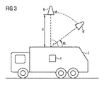
データ処理ユニット3は、バーチャルカメラ6を図3に示すように制御する。データ処理ユニット3によって制御されている該バーチャルカメラ6は、図3から認識できる如く、鳥の視野からの車両Fを見たようなカメラ画像を供給する。基本設定において該バーチャルカメラ6は、車両Fのボディに対して鉛直90度、高さHの上空に仮想的に配置されている。バーチャルカメラ6のカメラ画像は、車両Fに設けられているサラウンド・ビュー・カメラのカメラ画像から、データ処理ユニット3によって算出されることができる。バーチャルカメラ6は、車両Fに対する相対的カメラ配向/オリエンテーションと車両Fに対する相対的位置/ポジションを有している。カメラ・サラウンド・ビュー・システム1のデータ処理ユニット3は、該バーチャルカメラ6のポジションとオリエンテーションに基づいて再・投影面を調節する。好ましくは、該バーチャルカメラ6のポジションとオリエンテーションは、設定自在である。図3に示される如く、例えば、該バーチャルカメラ6は、車両ボディ上空90度の鉛直方向ポジションを起点として傾けることが可能であり、その傾き角度αは、例えば、45度である。車両Fに対する車両カメラ6の間隔、乃至、高さは、図3に示されている例では、一定である。尚、相対ポジションだけでなく、付加的に、該車両カメラ6のオリエンテーションを調整することも可能である。ある可及的実施形態においては、データ処理ユニット3が、該バーチャルカメラ6のその時点における車両Fに対する相対的なポジションとオリエンテーションを、該バーチャルカメラ6のパラメータ・メモリーから読み出す。読み出されたバーチャルカメラ6のパラメータに応じて、アダプティブな再・投影面が、データ処理ユニット3によって、設定、乃至、調整され、表示手段4が、可能な限り多くのテクスチャー、乃至、カメラ情報を、歪みなく表示すると同時に、車両Fの側近周辺部にある障害物が、車両Fのドライバーが、容易に認識できる様にしている。可及的実施形態においては、該表示ユニット4は、タッチスクリーンである。車両Fのドライバー、乃至、ユーザーは、ある可及的実施形態においては、該タッチスクリーンに触れ、側近の車両周辺部にある障害物、例えば、区画された駐車スペースをマークするポールを明確に認識できる様に、バーチャルカメラ6のポジション及び/或いはオリエンテーションを設定、乃至、調整することができる。更なる可及的実施形態においては、車両周辺部にある障害物を可能な限りはっきりと詳細に認識するために、バーチャルカメラ6と観察する車両Fとの間隔、乃至、その高さを、ユーザーによって設定可能である。ここで言う障害物とは、車両Fの走行を道路表面において妨害する任意のオブジェクトであり、例えば、山積みになった雪、或いは、駐車スペースを区画するポールなどもその一例である。
The
図2は、車両の車両周辺部の歪みない表示を得るための本発明に係る方法のある実施形態を表すフローチャートを示している。 FIG. 2 shows a flowchart representing an embodiment of the method according to the invention for obtaining an undistorted display of the vehicle periphery of the vehicle.
第一ステップS1において、車両周辺部の複数のカメラ画像が、車両Fの車載カメラ2によって作成される。例えば、カメラ画像は、車両の様々な側面に配置されている複数の車載カメラ2によって作成されることができる。
In the first step S <b> 1, a plurality of camera images around the vehicle periphery are created by the in-
作成されたカメラ画像は、続いて、ステップS2において、車両周辺部の周辺画像を生成するために処理される。ある可及的実施形態においては、作成されたカメラ画像の処理は、図1に示すようなデータ処理ユニット3によって実施される。該カメラ画像は、対応する周辺画像を生成するために、好ましくは、リアルタイムに処理される。
The created camera image is subsequently processed in step S2 to generate a peripheral image of the vehicle periphery. In a possible embodiment, the processing of the created camera image is performed by a
次のステップS3では、提供されたセンサーデータをベースに再・投影面が、算出され、続いて、車載カメラによって捕捉されたテクスチャーが、このアダプティブな算出された再・投影面に再・投影される。該アダプティブな再・投影面は、提供されるセンサーデータを基に動的に変化する、動的な可変なグリッドを有している。尚、該グリッドは、好ましくは、三次元のグリッドである。 In the next step S3, a re-projection plane is calculated based on the provided sensor data, and then the texture captured by the in-vehicle camera is re-projected onto this adaptive calculated re-projection plane. The The adaptive re-projection plane has a dynamically variable grid that changes dynamically based on provided sensor data. The grid is preferably a three-dimensional grid.
ステップS4では、再・投影面が、データ処理ユニット3により、車両Fの鳥瞰図的カメラ画像を供給するバーチャルカメラ6のポジション及び/或いはオリエンテーションに応じて調節される。
In
図2に示されている方法は、ある可及的実施形態においては、マイクロプロセッサーによって実施可能なコンピューター命令を含むコンピューター・プログラムに実装されていることもできる。該プログラムは、ある可及的実施形態においては、データ記憶媒体、或いは、プログラム・メモリーに保存されている。 The method illustrated in FIG. 2 may be implemented in a computer program that includes computer instructions executable by a microprocessor in certain possible embodiments. In some possible embodiments, the program is stored in a data storage medium or program memory.
Claims (15)
(a)車両(F)の車載カメラ(2)によって車両周辺部のカメラ画像を作成するステップ(S1)、
(b)作成されたカメラ画像を車両周辺部の周辺画像を作成するために処理するステップ(S2)、
(c)車載カメラ(2)によって捕捉されたテクスチャーを、車載センサー類(5)によって提供されたセンサーデータをベースに算出されたアダプティブな車両周辺部に近似した再・投影面に再・投影するステップ(S3)、
(d)車両(F)の鳥瞰図的カメラ画像を供給するバーチャルカメラ(6)の位置、及び/或いは、向きに応じて該再・投影面を調整するステップ(S4)。 A method for obtaining an undistorted display of the vehicle periphery of the vehicle (F) characterized in that it comprises the following steps:
(A) Step (S1) of creating a camera image of the vehicle periphery by the vehicle-mounted camera (2) of the vehicle (F),
(B) a step (S2) of processing the created camera image to create a peripheral image of the vehicle periphery;
(C) Re-projecting the texture captured by the in-vehicle camera (2) onto a re-projection surface that approximates the adaptive vehicle periphery calculated based on the sensor data provided by the in-vehicle sensors (5). Step (S3),
(D) A step of adjusting the re-projection plane according to the position and / or orientation of the virtual camera (6) that supplies the bird's-eye view camera image of the vehicle (F) (S4).
Applications Claiming Priority (3)
| Application Number | Priority Date | Filing Date | Title |
|---|---|---|---|
| DE102015202863.1 | 2015-02-17 | ||
| DE102015202863.1A DE102015202863A1 (en) | 2015-02-17 | 2015-02-17 | Method and device for the distortion-free display of a vehicle environment of a vehicle |
| PCT/DE2016/200074 WO2016131452A1 (en) | 2015-02-17 | 2016-02-04 | Method and device for the distortion-free display of an area surrounding a vehicle |
Publications (2)
| Publication Number | Publication Date |
|---|---|
| JP2018509799A true JP2018509799A (en) | 2018-04-05 |
| JP2018509799A5 JP2018509799A5 (en) | 2019-01-24 |
Family
ID=55661011
Family Applications (1)
| Application Number | Title | Priority Date | Filing Date |
|---|---|---|---|
| JP2017538401A Pending JP2018509799A (en) | 2015-02-17 | 2016-02-04 | Method and apparatus for distortion-free display of the vehicle periphery of a vehicle |
Country Status (7)
| Country | Link |
|---|---|
| US (1) | US20170341582A1 (en) |
| EP (1) | EP3259907A1 (en) |
| JP (1) | JP2018509799A (en) |
| KR (1) | KR20170118077A (en) |
| CN (1) | CN107249934B (en) |
| DE (2) | DE102015202863A1 (en) |
| WO (1) | WO2016131452A1 (en) |
Families Citing this family (7)
| Publication number | Priority date | Publication date | Assignee | Title |
|---|---|---|---|---|
| DE102015221340B4 (en) * | 2015-10-30 | 2021-02-25 | Conti Temic Microelectronic Gmbh | Device and method for providing a vehicle environment view for a vehicle |
| DE102017216822A1 (en) | 2017-09-22 | 2019-03-28 | Continental Automotive Gmbh | An apparatus and method for adjusting image processing based on a shape of a display device for a motor vehicle |
| CN107948501A (en) * | 2017-10-30 | 2018-04-20 | 深圳市易成自动驾驶技术有限公司 | Automatic ring vision method, device and computer-readable recording medium |
| JP7163732B2 (en) * | 2018-11-13 | 2022-11-01 | トヨタ自動車株式会社 | Driving support device, driving support system, driving support method and program |
| DE102019204656A1 (en) * | 2019-04-02 | 2020-10-08 | Conti Temic Microelectronic Gmbh | Parking assistance system |
| CN113353067A (en) * | 2021-07-14 | 2021-09-07 | 重庆大学 | Multi-environment detection and multi-mode matching parallel parking path planning system based on panoramic camera |
| CN113607203A (en) * | 2021-07-30 | 2021-11-05 | 武汉路特斯汽车有限公司 | Control method and system of vehicle sensor and vehicle |
Citations (5)
| Publication number | Priority date | Publication date | Assignee | Title |
|---|---|---|---|---|
| WO2011158344A1 (en) * | 2010-06-16 | 2011-12-22 | コニカミノルタオプト株式会社 | Image processing method, program, image processing device, and imaging device |
| JP2013137698A (en) * | 2011-12-28 | 2013-07-11 | Suzuki Motor Corp | Overhead view image presentation device |
| JP2014060646A (en) * | 2012-09-19 | 2014-04-03 | Fujitsu Ten Ltd | Image processing apparatus, image processing method, and image processing system |
| JP2014197818A (en) * | 2013-03-29 | 2014-10-16 | 富士通テン株式会社 | Image processing unit, image processing method and image processing system |
| JP2015015527A (en) * | 2013-07-03 | 2015-01-22 | クラリオン株式会社 | Video display system, video synthesis device and video synthesis method |
Family Cites Families (10)
| Publication number | Priority date | Publication date | Assignee | Title |
|---|---|---|---|---|
| JPH05638A (en) * | 1991-06-24 | 1993-01-08 | Sony Corp | On-vehicle monitoring device |
| FR2853121B1 (en) * | 2003-03-25 | 2006-12-15 | Imra Europe Sa | DEVICE FOR MONITORING THE SURROUNDINGS OF A VEHICLE |
| JP2008217267A (en) * | 2007-03-01 | 2008-09-18 | Denso Corp | Road shape recognition apparatus |
| CN101442618A (en) * | 2008-12-31 | 2009-05-27 | 葛晨阳 | Method for synthesizing 360 DEG ring-shaped video of vehicle assistant drive |
| DE102010042063B4 (en) * | 2010-10-06 | 2021-10-28 | Robert Bosch Gmbh | Method and device for determining processed image data about the surroundings of a vehicle |
| CN102142138A (en) * | 2011-03-23 | 2011-08-03 | 深圳市汉华安道科技有限责任公司 | Image processing method and subsystem in vehicle assisted system |
| KR101265711B1 (en) * | 2011-11-30 | 2013-05-20 | 주식회사 이미지넥스트 | 3d vehicle around view generating method and apparatus |
| US20130293683A1 (en) * | 2012-05-03 | 2013-11-07 | Harman International (Shanghai) Management Co., Ltd. | System and method of interactively controlling a virtual camera |
| DE102012018325A1 (en) * | 2012-09-15 | 2014-03-20 | DSP-Weuffen GmbH | Method and device for an imaging driver assistance system with adaptive prudential presentation |
| DE102012018326B4 (en) * | 2012-09-15 | 2019-12-19 | Zf Friedrichshafen Ag | Method and device for an imaging driver assistance system with concealment-free foresight function |
-
2015
- 2015-02-17 DE DE102015202863.1A patent/DE102015202863A1/en not_active Withdrawn
-
2016
- 2016-02-04 WO PCT/DE2016/200074 patent/WO2016131452A1/en active Application Filing
- 2016-02-04 EP EP16714224.9A patent/EP3259907A1/en active Pending
- 2016-02-04 JP JP2017538401A patent/JP2018509799A/en active Pending
- 2016-02-04 KR KR1020177022638A patent/KR20170118077A/en not_active Application Discontinuation
- 2016-02-04 CN CN201680010084.4A patent/CN107249934B/en active Active
- 2016-02-04 DE DE112016000188.6T patent/DE112016000188A5/en active Pending
-
2017
- 2017-08-17 US US15/679,603 patent/US20170341582A1/en not_active Abandoned
Patent Citations (5)
| Publication number | Priority date | Publication date | Assignee | Title |
|---|---|---|---|---|
| WO2011158344A1 (en) * | 2010-06-16 | 2011-12-22 | コニカミノルタオプト株式会社 | Image processing method, program, image processing device, and imaging device |
| JP2013137698A (en) * | 2011-12-28 | 2013-07-11 | Suzuki Motor Corp | Overhead view image presentation device |
| JP2014060646A (en) * | 2012-09-19 | 2014-04-03 | Fujitsu Ten Ltd | Image processing apparatus, image processing method, and image processing system |
| JP2014197818A (en) * | 2013-03-29 | 2014-10-16 | 富士通テン株式会社 | Image processing unit, image processing method and image processing system |
| JP2015015527A (en) * | 2013-07-03 | 2015-01-22 | クラリオン株式会社 | Video display system, video synthesis device and video synthesis method |
Also Published As
| Publication number | Publication date |
|---|---|
| WO2016131452A1 (en) | 2016-08-25 |
| CN107249934A (en) | 2017-10-13 |
| DE102015202863A1 (en) | 2016-08-18 |
| CN107249934B (en) | 2021-01-12 |
| US20170341582A1 (en) | 2017-11-30 |
| EP3259907A1 (en) | 2017-12-27 |
| KR20170118077A (en) | 2017-10-24 |
| DE112016000188A5 (en) | 2017-08-31 |
Similar Documents
| Publication | Publication Date | Title |
|---|---|---|
| JP6860348B2 (en) | Methods and devices for distortion-free display of the vehicle's peripheral area | |
| JP2018509799A (en) | Method and apparatus for distortion-free display of the vehicle periphery of a vehicle | |
| JP2021170826A (en) | Method and apparatus for displaying peripheral scene of combination of vehicle and tracked vehicle | |
| JP2018531530A6 (en) | Method and apparatus for displaying surrounding scene of vehicle / towed vehicle combination | |
| CN107027329B (en) | Stitching together partial images of the surroundings of a running tool into one image | |
| JP7156937B2 (en) | Image processing device and image processing method | |
| JP2018509799A5 (en) | ||
| JP2013187562A (en) | Posterior sight support device for vehicle | |
| CN110651295B (en) | Image processing apparatus, image processing method, and program | |
| US10412359B2 (en) | Method for generating a virtual image of vehicle surroundings | |
| KR102057021B1 (en) | Panel transformation | |
| EP3002727A1 (en) | Periphery monitoring apparatus and periphery monitoring system | |
| US20190100141A1 (en) | Ascertainment of Vehicle Environment Data | |
| JP2014165810A (en) | Parameter acquisition device, parameter acquisition method and program | |
| KR20180021822A (en) | Rear Cross Traffic - QuickLux | |
| JP2019054439A (en) | Image processing system | |
| CN113838060A (en) | Perception system for autonomous vehicle | |
| JP2008213647A (en) | Parking assist method and parking assist system | |
| JP5305750B2 (en) | Vehicle periphery display device and display method thereof | |
| WO2021131481A1 (en) | Display device, display method, and display program | |
| JP2013197816A (en) | On-board image display device | |
| JP2007028443A (en) | Image display system | |
| JP2007028442A (en) | Image display system | |
| WO2019074065A1 (en) | Image processing device | |
| JP6020736B2 (en) | Predicted course presentation device and predicted course presentation method |
Legal Events
| Date | Code | Title | Description |
|---|---|---|---|
| A529 | Written submission of copy of amendment under article 34 pct |
Free format text: JAPANESE INTERMEDIATE CODE: A529 Effective date: 20170720 |
|
| A621 | Written request for application examination |
Free format text: JAPANESE INTERMEDIATE CODE: A621 Effective date: 20170720 |
|
| A977 | Report on retrieval |
Free format text: JAPANESE INTERMEDIATE CODE: A971007 Effective date: 20180914 |
|
| A131 | Notification of reasons for refusal |
Free format text: JAPANESE INTERMEDIATE CODE: A131 Effective date: 20180926 |
|
| A524 | Written submission of copy of amendment under article 19 pct |
Free format text: JAPANESE INTERMEDIATE CODE: A524 Effective date: 20181205 |
|
| A131 | Notification of reasons for refusal |
Free format text: JAPANESE INTERMEDIATE CODE: A131 Effective date: 20190320 |
|
| A521 | Request for written amendment filed |
Free format text: JAPANESE INTERMEDIATE CODE: A523 Effective date: 20190618 |
|
| A02 | Decision of refusal |
Free format text: JAPANESE INTERMEDIATE CODE: A02 Effective date: 20191204 |
|
| A521 | Request for written amendment filed |
Free format text: JAPANESE INTERMEDIATE CODE: A523 Effective date: 20200327 |
|
| C60 | Trial request (containing other claim documents, opposition documents) |
Free format text: JAPANESE INTERMEDIATE CODE: C60 Effective date: 20200327 |
|
| A911 | Transfer to examiner for re-examination before appeal (zenchi) |
Free format text: JAPANESE INTERMEDIATE CODE: A911 Effective date: 20200408 |
|
| C21 | Notice of transfer of a case for reconsideration by examiners before appeal proceedings |
Free format text: JAPANESE INTERMEDIATE CODE: C21 Effective date: 20200415 |
|
| A912 | Re-examination (zenchi) completed and case transferred to appeal board |
Free format text: JAPANESE INTERMEDIATE CODE: A912 Effective date: 20200626 |
|
| C211 | Notice of termination of reconsideration by examiners before appeal proceedings |
Free format text: JAPANESE INTERMEDIATE CODE: C211 Effective date: 20200701 |
|
| RD04 | Notification of resignation of power of attorney |
Free format text: JAPANESE INTERMEDIATE CODE: A7424 Effective date: 20200703 |
|
| C22 | Notice of designation (change) of administrative judge |
Free format text: JAPANESE INTERMEDIATE CODE: C22 Effective date: 20200819 |
|
| C22 | Notice of designation (change) of administrative judge |
Free format text: JAPANESE INTERMEDIATE CODE: C22 Effective date: 20201014 |
|
| C13 | Notice of reasons for refusal |
Free format text: JAPANESE INTERMEDIATE CODE: C13 Effective date: 20210428 |
|
| A601 | Written request for extension of time |
Free format text: JAPANESE INTERMEDIATE CODE: A601 Effective date: 20210706 |
|
| C23 | Notice of termination of proceedings |
Free format text: JAPANESE INTERMEDIATE CODE: C23 Effective date: 20211006 |
|
| C03 | Trial/appeal decision taken |
Free format text: JAPANESE INTERMEDIATE CODE: C03 Effective date: 20211110 |
|
| C30A | Notification sent |
Free format text: JAPANESE INTERMEDIATE CODE: C3012 Effective date: 20211110 |