JP2018509237A - Cable mover - Google Patents

Cable mover Download PDF

Info

Publication number
JP2018509237A
JP2018509237A JP2017549693A JP2017549693A JP2018509237A JP 2018509237 A JP2018509237 A JP 2018509237A JP 2017549693 A JP2017549693 A JP 2017549693A JP 2017549693 A JP2017549693 A JP 2017549693A JP 2018509237 A JP2018509237 A JP 2018509237A
Authority
JP
Japan
Prior art keywords
arm
cable
mover
housing
main assembly
Prior art date
Legal status (The legal status is an assumption and is not a legal conclusion. Google has not performed a legal analysis and makes no representation as to the accuracy of the status listed.)
Granted
Application number
JP2017549693A
Other languages
Japanese (ja)
Other versions
JP2018509237A5 (en
JP6754371B2 (en
Inventor
ロバート アラン メニヤー,
ロバート アラン メニヤー,
アンドリュー ケー. トムフォード,
アンドリュー ケー. トムフォード,
ロバート ハースト,
ロバート ハースト,
Current Assignee (The listed assignees may be inaccurate. Google has not performed a legal analysis and makes no representation or warranty as to the accuracy of the list.)
Capital Safety Group Northen Europe Ltd
Original Assignee
Capital Safety Group Northen Europe Ltd
Priority date (The priority date is an assumption and is not a legal conclusion. Google has not performed a legal analysis and makes no representation as to the accuracy of the date listed.)
Filing date
Publication date
Application filed by Capital Safety Group Northen Europe Ltd filed Critical Capital Safety Group Northen Europe Ltd
Publication of JP2018509237A publication Critical patent/JP2018509237A/en
Publication of JP2018509237A5 publication Critical patent/JP2018509237A5/ja
Application granted granted Critical
Publication of JP6754371B2 publication Critical patent/JP6754371B2/en
Active legal-status Critical Current
Anticipated expiration legal-status Critical

Links

Images

Classifications

    • AHUMAN NECESSITIES
    • A62LIFE-SAVING; FIRE-FIGHTING
    • A62BDEVICES, APPARATUS OR METHODS FOR LIFE-SAVING
    • A62B1/00Devices for lowering persons from buildings or the like
    • A62B1/06Devices for lowering persons from buildings or the like by making use of rope-lowering devices
    • A62B1/14Devices for lowering persons from buildings or the like by making use of rope-lowering devices with brakes sliding on the rope
    • AHUMAN NECESSITIES
    • A62LIFE-SAVING; FIRE-FIGHTING
    • A62BDEVICES, APPARATUS OR METHODS FOR LIFE-SAVING
    • A62B35/00Safety belts or body harnesses; Similar equipment for limiting displacement of the human body, especially in case of sudden changes of motion
    • A62B35/0081Equipment which can travel along the length of a lifeline, e.g. travelers

Abstract

新規なケーブル移動器を提供するものである。このケーブル移動器は、ハウジングと、主アセンブリと、逆さ取付防止爪とを含む。ハウジングは、少なくとも1つのケーブルガイド通路を形成する。主アセンブリは、ハウジングに枢動可能に取り付けられる。主アセンブリは、ケーブルが少なくとも1つのケーブルガイド通路内に配置されることを可能にする開いた形態と、少なくとも1つのケーブルガイド通路内のケーブルと係合する閉じた形態とを有するように構成され配置されている。逆さ取付防止爪は、ハウジングが逆向きにあるときに主アセンブリの動きを選択的に制限するように構成され配置されている。【選択図】図3BA new cable mover is provided. The cable mover includes a housing, a main assembly, and an upside down prevention pawl. The housing forms at least one cable guide passage. The main assembly is pivotally attached to the housing. The main assembly is configured to have an open configuration that allows a cable to be disposed in at least one cable guide passage and a closed configuration that engages a cable in the at least one cable guide passage. Has been placed. The inverted mounting prevention pawl is constructed and arranged to selectively limit movement of the main assembly when the housing is in the reverse orientation. [Selection] Figure 3B

Description

高所で作業を行う作業員は、落下事故が万が一発生した場合に落下を制限して作業者が怪我をする可能性を減らすよう、通常、支持構造物に接続される安全ハーネスを着用する。はしごや塔などの構造物を登ったり降りたりしている間に起こり得る落下事故の際に作業者を保護するシステムにはいくつかのタイプがある。   Workers working at high altitudes usually wear safety harnesses connected to the support structure to limit the fall and reduce the possibility of injury to the operator in the event of a fall accident. There are several types of systems that protect workers in the event of a fall accident that can occur while climbing or descending structures such as ladders and towers.

1つのタイプのシステムは、ケーブルと、ケーブルに沿っていずれかの方向に移動する移動器(traveler)とを含む。ランヤードが、通常、移動器と作業者の安全ハーネスとを相互接続する。落下が発生した場合、移動器はケーブルと係合し、落下を制限する。しかし、移動器がケーブルに正しく取り付けられているかどうかを判断することは困難な場合がある。また、落下が発生した場合に設計どおりに機能するように移動器を正しく取り付けることが重要である。   One type of system includes a cable and a traveler that moves in either direction along the cable. A lanyard typically interconnects the mobile and the operator's safety harness. If a drop occurs, the mobile will engage the cable and limit the drop. However, it can be difficult to determine whether the mobile is properly attached to the cable. It is also important that the mobile device is correctly installed so that it will function as designed if a drop occurs.

本明細書を読み解釈することで当業者には明らかになるであろう、上記の理由及び以下に述べる他の理由のために、誤って取り付けられている場合又は誤って取り付けられた場合を示すケーブル移動器がこの分野において必要とされている。   Shows if mis-installed or mis-installed for the reasons described above and other reasons described below, which will be apparent to those skilled in the art upon reading and interpreting this specification. A cable mover is needed in this field.

従来の装置に関連する上述の問題は、本発明の実施形態によって対処され、本明細書を読み解釈することによって理解されるであろう。以下の概要は、限定ではなく、例として記載されたものである。以下の概要は、読者が本発明の態様のいくつかを理解するのを助けるために提供されるに過ぎない。   The above-mentioned problems associated with conventional devices are addressed by embodiments of the present invention and will be understood by reading and interpreting this specification. The following summary is provided by way of example and not limitation. The following summary is provided only to assist the reader in understanding some of the aspects of the present invention.

一実施形態において、ケーブル移動器が提供される。ケーブル移動器は、ハウジングと、主アセンブリと、逆さ取付防止爪(anti−inversion pawl)とを含む。ハウジングは、少なくとも1つのケーブルガイド通路を形成している。主アセンブリは、ハウジングに枢動可能に取り付けられている。主アセンブリは、ケーブルが少なくとも1つのケーブルガイド通路内に配置されることを可能にする開いた形態(以下「開形態」ともいう)と、少なくとも1つのケーブルガイド通路内のケーブルと係合する閉じた形態(以下「閉形態」ともいう)とを有するように構成され配置されている。逆さ取付防止爪は、ハウジングが逆向きにあるときに主アセンブリの動きを選択的に制限するように構成され配置されている。   In one embodiment, a cable mover is provided. The cable mover includes a housing, a main assembly, and an anti-inversion pawl. The housing forms at least one cable guide passage. The main assembly is pivotally attached to the housing. The main assembly has an open configuration (hereinafter also referred to as an “open configuration”) that allows the cable to be disposed in at least one cable guide passage and a closure that engages the cable in the at least one cable guide passage. And is arranged so as to have a form (hereinafter also referred to as “closed form”). The inverted mounting prevention pawl is constructed and arranged to selectively limit movement of the main assembly when the housing is in the reverse orientation.

別の実施形態では、別のケーブル移動器が提供される。このケーブル移動器は、ハウジングと、コントロールアームと、主アセンブリと、プランジャとを含む。ハウジングは、少なくとも1つのケーブルガイド通路を形成している。コントロールアームは、ハウジングに枢動可能に結合されている。コントロールアームは、落下防止システムをケーブル移動器に結合するように構成され配置された取付アイ(attachment eye)を有する。主アセンブリは、ハウジングに枢動可能に取り付けられている。主アセンブリは、ケーブルが少なくとも1つのケーブルガイド通路内に配置されることを可能にする開形態と、少なくとも1つのケーブルガイド通路内のケーブルと係合する閉形態とを有するように構成され配置されている。プランジャは、主アセンブリの移動を選択的に制限するように構成されている。プランジャは、主要部分と、延長アームストッパと、プランジャ付勢部材とを含む。主要部分は、ハウジングに移動可能に結合されている。延長アームストッパは主要部分から延びている。さらに、延長アームストッパは、ハウジング内のストッパスロット通路に収容される。プランジャ付勢部材は、延長アームストッパをハウジング内のストップスロット通路に付勢して主アセンブリと選択的に係合するように構成され配置されている。   In another embodiment, another cable mover is provided. The cable mover includes a housing, a control arm, a main assembly, and a plunger. The housing forms at least one cable guide passage. The control arm is pivotally coupled to the housing. The control arm has an attachment eye constructed and arranged to couple the fall prevention system to the cable mover. The main assembly is pivotally attached to the housing. The main assembly is configured and arranged to have an open configuration that allows a cable to be disposed in at least one cable guide passage and a closed configuration that engages a cable in the at least one cable guide passage. ing. The plunger is configured to selectively limit movement of the main assembly. The plunger includes a main portion, an extension arm stopper, and a plunger biasing member. The main part is movably coupled to the housing. The extension arm stopper extends from the main portion. Further, the extension arm stopper is accommodated in a stopper slot passage in the housing. The plunger biasing member is constructed and arranged to bias the extension arm stopper into a stop slot passage in the housing to selectively engage the main assembly.

さらに別の実施形態では、ケーブル移動器を形成する方法が提供される。この方法は、主アセンブリをハウジングに枢動可能に取り付けられることを含む。主アセンブリは、ケーブルがハウジングのケーブルガイド通路内に配置されることを可能にする開形態と、少なくとも1つのケーブルガイド通路内のケーブルと係合する閉形態との間で動作するように構成され配置される。この方法はさらに、ハウジングが逆向きであるときに主アセンブリの動きを制限することを含む。   In yet another embodiment, a method for forming a cable mover is provided. The method includes pivotally attaching the main assembly to the housing. The main assembly is configured to operate between an open configuration that allows the cable to be disposed within the cable guide passage of the housing and a closed configuration that engages the cable in at least one cable guide passage. Be placed. The method further includes limiting the movement of the main assembly when the housing is upside down.

本発明は、以下の詳細な説明及び添付の図面を考慮することで、より容易に理解することができ、さらなる利点及び使用法はより明らかになるであろう。   The present invention can be more readily understood and further advantages and uses will become more apparent upon consideration of the following detailed description and the accompanying drawings.

本発明の一実施形態によるケーブル移動器を示す第1の側からの斜視図である。It is a perspective view from the 1st side which shows the cable mover by one Embodiment of this invention. 図1のケーブル移動器を示す第1の側からの分解斜視図である。It is a disassembled perspective view from the 1st side which shows the cable mover of FIG. ケーブルに取り付けるべく最初に配置された図1のケーブル移動器を示す第1の側からの斜視図である。FIG. 2 is a perspective view from a first side showing the cable mover of FIG. 1 initially positioned for attachment to a cable. 開形態でケーブルに配置された図1のケーブル移動器を示す第1の側からの斜視図である。FIG. 2 is a perspective view from a first side illustrating the cable mover of FIG. 1 disposed on a cable in an open configuration. 閉形態でケーブルに配置された図1のケーブル移動器を示す第1の側からの斜視図である。FIG. 2 is a perspective view from a first side showing the cable mover of FIG. 1 placed on a cable in a closed configuration. 本発明の一実施形態による落下防止システムの一部に接続された図1のケーブル移動器の背面図である。FIG. 2 is a rear view of the cable mover of FIG. 1 connected to a portion of a fall prevention system according to an embodiment of the present invention. 図4Aの落下防止システムの一部及びケーブル移動器を示す第1の側からの側面図である。It is a side view from the 1st side which shows a part of fall prevention system of Drawing 4A, and a cable mover. 開形態の図1のケーブル移動器を示す第2の側からの側面図である。FIG. 3 is a side view from the second side showing the cable mover of FIG. 1 in an open configuration. 開形態の図1のケーブル移動器を示す第1の側からの側面図である。FIG. 2 is a side view from the first side showing the cable mover of FIG. 1 in an open configuration. 一実施形態の逆さ取付防止爪を示す、図1のケーブル移動器の第1の側からの斜視図である。It is a perspective view from the 1st side of the cable mover of FIG. 1 which shows the inverted attachment prevention nail | claw of one Embodiment. 逆さ取付防止爪をさらに示す、逆向きの図1のケーブル移動器の第1の側からの斜視図である。FIG. 2 is a perspective view from the first side of the cable mover of FIG. 1 in an inverted orientation, further showing an inverted mounting prevention claw. ケーブル移動器が逆向きの水平方向に配置された直後の図1のケーブル移動器を示す背面図である。It is a rear view which shows the cable mover of FIG. 1 just after a cable mover is arrange | positioned in the reverse horizontal direction. 逆さ取付防止爪が移動した後の逆向きの水平方向における図1のケーブル移動器を示す背面図である。It is a rear view which shows the cable moving device of FIG. 1 in the horizontal direction of the reverse direction after an inverted attachment prevention nail | claw moved. ケーブル移動器が逆向きの垂直方向に配置された直後の図1のケーブル移動器を示す背面図である。It is a rear view which shows the cable mover of FIG. 1 just after a cable mover is arrange | positioned in the reverse perpendicular direction. 逆さ取付防止爪が移動した後の逆向きの垂直方向における図1のケーブル移動器を示す背面図である。It is a rear view which shows the cable mover of FIG. 1 in the reverse perpendicular direction after an inverted attachment prevention nail | claw moved. 本発明の別の実施形態のケーブル移動器を示す第1の側からの斜視図である。It is a perspective view from the 1st side which shows the cable mover of another embodiment of this invention. 図11のケーブル移動器を示す第1の側からの分解斜視図である。It is a disassembled perspective view from the 1st side which shows the cable mover of FIG. ケーブルに取り付けるべく最初に配置された図11のケーブル移動器を示す第1の側からの斜視図である。FIG. 12 is a perspective view from the first side showing the cable mover of FIG. 11 initially positioned for attachment to a cable. 開形態でケーブルに配置された図11のケーブル移動器を示す第1の側からの斜視図である。FIG. 12 is a perspective view from a first side showing the cable mover of FIG. 11 placed on a cable in an open configuration. 閉形態でケーブルに配置された図11のケーブル移動器を示す第1の側からの斜視図である。FIG. 12 is a perspective view from the first side showing the cable mover of FIG. 11 placed on the cable in a closed configuration; 図11のケーブル移動器の背面図である。It is a rear view of the cable mover of FIG. 閉形態の図11のケーブル移動器を示す第1の側からの側面図である。FIG. 12 is a side view from the first side showing the cable mover of FIG. 11 in a closed configuration. 開形態の図11のケーブル移動器を示す第2の側からの側面図である。FIG. 12 is a side view from the second side showing the cable mover of FIG. 11 in an open configuration. 開形態の図11のケーブル移動器を示す第1の側からの側面図である。FIG. 12 is a side view from the first side showing the cable mover of FIG. 11 in an open configuration. 一実施形態の逆さ取付防止爪を示す、図11のケーブル移動器の第1の側からの斜視図である。FIG. 12 is a perspective view from the first side of the cable mover of FIG. 11 showing the inverted mounting prevention pawl of one embodiment. 本出願の別の実施形態による逆転防止爪の構成を示すケーブル移動器の第1の側からの斜視図である。It is a perspective view from the 1st side of the cable mover which shows the structure of the reverse rotation prevention claw by another embodiment of this application. 逆向きにある逆さ取付防止爪を示す、図11のケーブル移動器の第1の側からの斜視図である。It is a perspective view from the 1st side of the cable mover of FIG. 11 which shows the reverse attachment prevention nail | claw in a reverse direction. 逆向き位置にある逆さ取付防止爪を示す、図17Bのケーブル移動器の第1の側からの斜視図である。FIG. 18B is a perspective view from the first side of the cable mover of FIG. 17B showing the upside down prevention pawl in the reverse position. ケーブル移動器が逆向きの水平方向に配置された直後の図11のケーブル移動器を示す背面図である。It is a rear view which shows the cable mover of FIG. 11 just after a cable mover is arrange | positioned in the reverse horizontal direction. 逆さ取付防止爪が移動した後の、逆向きの水平方向に配置された図11のケーブル移動器を示す背面図である。It is a rear view which shows the cable mover of FIG. 11 arrange | positioned in the horizontal direction of an opposite direction after an inverted attachment prevention nail | claw moved. ケーブル移動器が逆向きの垂直方向に配置された直後の図11のケーブル移動器を示す背面図である。It is a rear view which shows the cable mover of FIG. 11 just after a cable mover is arrange | positioned in the reverse perpendicular direction. 逆さ取付防止爪が移動した後の、逆向きの垂直方向に配置された図11のケーブル移動器を示す背面図である。FIG. 12 is a rear view of the cable mover of FIG. 11 arranged in the reverse vertical direction after the upside down prevention claws have moved. 一実施形態のプランジャの動作を示す図11のケーブル移動器の部分側面図である。FIG. 12 is a partial side view of the cable mover of FIG. 11 illustrating the operation of the plunger of one embodiment.

通常通り、図において、以下で説明する様々な特徴部は一定の縮尺で描かれておらず、また、本発明に関連する特定の特徴部を強調するよう描かれている。参照符号は、図面及び本明細書全体を通して同様の要素を示すものとする。   As usual, the various features described below are not drawn to scale and are drawn to emphasize specific features relevant to the present invention. Reference characters denote like elements throughout the drawings and the specification.

以下の詳細な説明では、本発明の一部を形成する添付の図面を参照し、本発明を実施することができる例示的実施形態を示す。これらの実施形態は、当業者が本発明を実施できるように十分に詳細に記載されており、本発明の精神及び範囲から逸脱することなく他の実施形態を利用し、機械的な変更を行うことができることを理解されたい。したがって、以下の詳細な説明は、限定的な意味で解釈されるべきではなく、本発明の範囲は、特許請求の範囲及びその等価物によってのみ規定される。   In the following detailed description, reference is made to the accompanying drawings that form a part hereof, and in which is shown by way of illustration exemplary embodiments in which the invention may be practiced. These embodiments are described in sufficient detail to enable those skilled in the art to practice the invention, and other embodiments may be utilized and mechanical changes may be made without departing from the spirit and scope of the invention. Please understand that you can. The following detailed description is, therefore, not to be taken in a limiting sense, and the scope of the present invention is defined only by the appended claims and equivalents thereof.

本発明の実施形態によれば、ケーブル移動器が取り付けられるケーブルに対してケーブル移動器が不正確に配置されたときに、ケーブル移動器が作動することを防止するように構成されたケーブル移動器が提供される。また、これらの実施形態は、以下で詳細に説明するが、動的平行四辺形構造(dynamic parallelogram geometry)を有する主アセンブリを用いており、これによって、互いに対向する平行構成要素同士が互いに最も近いときである開いた形態と、互いに対向する平行構成要素同士が互いに最も離れたときである閉じた形態とをとることができる。いくつかの実施形態では、ケーブル移動器が正しくなく逆さに取り付けられているとき、ケーブル移動器がケーブルに誤って取り付けられるのを防止するために、以下に詳細に説明するように、平行四辺形構造が逆さ取付防止爪によって制限される。さらに、一実施形態では、ケーブル移動器がケーブルに適正に取り付けられるまで、ケーブル移動器への安全保護システムの取付けを防止するため、ケーブル移動器(又はケーブル移動器の主アセンブリ)が開いた形態にあるとき、取付アイは少なくとも部分的に閉鎖される。これも以下で詳細に説明する。上記実施形態をケーブル移動器の特徴として示し説明したが、ケーブル移動器が誤って取り付けられていること、又は誤って取り付けられたことを示すために、これらの特徴の一つ又は両方を使用され得ることは理解されたい。言い換えるならば、ケーブル移動器は、本体の動きを妨げる又は取付アイの閉鎖を妨げる逆さ取付防止爪を含むことができる。さらに、ケーブル移動器は、これらの特徴及び以下に詳細に説明する他の特徴の両方を含むことができる。   According to an embodiment of the present invention, a cable mover configured to prevent the cable mover from operating when the cable mover is incorrectly placed relative to the cable to which the cable mover is attached. Is provided. Also, these embodiments, which will be described in detail below, use a main assembly having a dynamic parallelogram geometry so that opposing parallel components are closest to each other. It can take an open form that is sometimes and a closed form that is when the mutually opposite parallel components are farthest apart from each other. In some embodiments, when the cable mover is mounted incorrectly and upside down, in order to prevent the cable mover from being incorrectly attached to the cable, as described in detail below, a parallelogram The structure is limited by the inverted mounting prevention claw. Further, in one embodiment, the cable mover (or the main assembly of the cable mover) is open to prevent the safety protection system from being attached to the cable mover until the cable mover is properly attached to the cable. The mounting eye is at least partially closed. This will also be described in detail below. While the above embodiments have been shown and described as cable mover features, one or both of these features may be used to indicate that the cable mover is incorrectly installed or has been incorrectly installed. It is understood that you get. In other words, the cable mover can include an upside down mounting pawl that prevents movement of the body or prevents closing of the mounting eye. Further, the cable mover can include both these features and other features described in detail below.

図1を参照すると、一実施形態のケーブル移動器100が示されている。図1では、ケーブル移動器100は、開位置にあるものとして示されている。閉位置にあるケーブル移動器100の例は図7に示されている。図2は、ケーブル移動器100の分解図を示している。ここでは、ケーブル移動器100について図1及び図2を参照して説明する。ケーブル移動器100は、ケーブル移動器100のハウジング195を構成する第1の本体プレート102と、第2の本体プレート104とを含む。第1の本体プレート102及び第2の本体プレート104は共に略L字形である。第1の本体プレート102は、第1の本体部分102aと、第2の本体部分102bとを含む。さらに、第1の本体プレート102は、第1のプレート縁部102cと、その反対側の第2のプレート縁部102dとを有するものとして説明することとする。第2の本体プレート104はまた、第1の本体部分104aと、第2の本体部分104bと、第1のプレート縁部104cと、その反対側の第2のプレート縁部104dとを含む。第1の本体プレート102の第1の本体部分102aは、上部接続開口107と、ケーブル開口109とを含む。ケーブル開口109は、第1の本体プレート102の第1の縁部102cの近傍に配置されている。第1の本体プレート102の第2の本体部分102bは、第2のプレート縁部102dから延びて下部ケーブルガイド通路103を形成するC字形下部ガイド102eを含む。第1の本体プレート102の第2の本体部分102bは、下部接続開口111をさらに含む。第2の本体プレート104の第1の本体部分104aは、第2のプレート縁部104dから延びて上部ケーブルガイド通路105を形成するC字形上部ガイド104eを含む。第2の本体プレート104は、第2の本体プレート104の第1の本体部分104aに設けられた上部接続開口115と、第2の本体プレート104の第2の本体部分104bに設けられた下部接続開口117とを含む。   Referring to FIG. 1, an embodiment of a cable mover 100 is shown. In FIG. 1, the cable mover 100 is shown as being in the open position. An example of a cable mover 100 in the closed position is shown in FIG. FIG. 2 shows an exploded view of the cable mover 100. Here, the cable mover 100 will be described with reference to FIGS. 1 and 2. The cable mover 100 includes a first body plate 102 and a second body plate 104 that constitute a housing 195 of the cable mover 100. Both the first main body plate 102 and the second main body plate 104 are substantially L-shaped. The first body plate 102 includes a first body portion 102a and a second body portion 102b. Further, the first main body plate 102 will be described as having a first plate edge 102c and a second plate edge 102d on the opposite side. The second body plate 104 also includes a first body portion 104a, a second body portion 104b, a first plate edge 104c, and a second plate edge 104d on the opposite side. The first body portion 102 a of the first body plate 102 includes an upper connection opening 107 and a cable opening 109. The cable opening 109 is disposed in the vicinity of the first edge portion 102 c of the first main body plate 102. The second body portion 102 b of the first body plate 102 includes a C-shaped lower guide 102 e that extends from the second plate edge 102 d and forms a lower cable guide passage 103. The second body portion 102 b of the first body plate 102 further includes a lower connection opening 111. The first body portion 104 a of the second body plate 104 includes a C-shaped upper guide 104 e that extends from the second plate edge 104 d and forms an upper cable guide passage 105. The second body plate 104 includes an upper connection opening 115 provided in the first body portion 104 a of the second body plate 104 and a lower connection provided in the second body portion 104 b of the second body plate 104. And an opening 117.

一実施形態では、第1の本体プレート102にケーブル114が接続されている。特に、ケーブルの第1の端部は、第1の本体プレート102におけるケーブル開口109を通される。ケーブルの第1の端部は、折り返され、第1のフェルール116によってそれ自体に締結される。一実施形態では、ケーブルの第2の端部は、折り返され、第2のフェルール118によってそれ自体に締結されて、ケーブルループ119を形成する。この実施形態のケーブル移動器100は、第1のラベル120と、第2のラベル124とを含む。第1のラベル120は、第1のラベル開口121と、そこから離間した第2のラベル開口123とを含む。第1のラベル120は、第1のラベル開口121が第1の本体プレート102の上部接続開口107と整列されるように、且つ、第2のラベル開口123が第1の本体プレート102の下部接続開口111と整列されるようにして、第1の本体プレート102に接着される。第2のラベル124は、第1のラベル開口125と、そこから離間した第2のラベル開口126とを含む。第2のラベル124は、第1のラベル開口125が第2の本体プレート104の上部接続開口115と整列するように、且つ、第2のラベル開口126が第2の本体プレート104の下部接続開口117と整列するようにして、第2の本体プレート104に接着される。   In one embodiment, a cable 114 is connected to the first body plate 102. In particular, the first end of the cable is passed through the cable opening 109 in the first body plate 102. The first end of the cable is folded and fastened to itself by the first ferrule 116. In one embodiment, the second end of the cable is folded and fastened to itself by the second ferrule 118 to form a cable loop 119. The cable mover 100 of this embodiment includes a first label 120 and a second label 124. The first label 120 includes a first label opening 121 and a second label opening 123 spaced therefrom. The first label 120 is such that the first label opening 121 is aligned with the upper connection opening 107 of the first body plate 102 and the second label opening 123 is the lower connection of the first body plate 102. It is adhered to the first body plate 102 so as to be aligned with the opening 111. The second label 124 includes a first label opening 125 and a second label opening 126 spaced therefrom. The second label 124 is such that the first label opening 125 is aligned with the upper connection opening 115 of the second body plate 104 and the second label opening 126 is the lower connection opening of the second body plate 104. Adhered to the second body plate 104 in alignment with 117.

ケーブル移動器100はさらに、第1のアームリンク130と、第2のアームリンク140とを含む。第1のアームリンク130は、第1の端部分130aと、その反対側の第2の端部分130bとを含む。第1の端部分130aは、細長い中間部分130cを介して第2の端部分130bから離間している。第1のアームリンク130の第1の端部分130aは第1のアーム開口131を含み、第1のアームリンク130の第2の端部分130bは第2のアーム開口133を含む。第1のアームリンク130の中間部分130cは、第1のアーム受入れスロット135を含む。第1のアーム受入れスロット135と第1のアーム開口131との間には、付勢端保持用開口137が配置されている。一実施形態では、第1のアームリンク130の第1の端部分130a及び第2の端部分130bの両方が、丸みの付けられた縁部で終端している。   The cable mover 100 further includes a first arm link 130 and a second arm link 140. The first arm link 130 includes a first end portion 130a and an opposite second end portion 130b. The first end portion 130a is spaced from the second end portion 130b via an elongated intermediate portion 130c. The first end portion 130 a of the first arm link 130 includes a first arm opening 131, and the second end portion 130 b of the first arm link 130 includes a second arm opening 133. The intermediate portion 130 c of the first arm link 130 includes a first arm receiving slot 135. A biasing end holding opening 137 is disposed between the first arm receiving slot 135 and the first arm opening 131. In one embodiment, both the first end portion 130a and the second end portion 130b of the first arm link 130 terminate at a rounded edge.

第2のアームリンク140は、第1の端部分140aと、その反対側の第2の端部分140bとを含む。第1の端部分140aは、細長い中間部分140cを介して第2の端部分140bから離間している。第2のアームリンク140の第1の端部分140aは第1のアーム開口141を含み、第2のアームリンク140の第2の端部分140bは第2のアーム開口143を含む。第2のアームリンク140の第1の端部分140a付近の中間部分140cには、第2のアーム受入れ通路145が設けられている。一実施形態では、第2のアームリンク140の第1の端部分140a及び第2の端部分140bの両方が、丸みの付けられた縁部で終端している。さらに、一実施形態では、第2の端部分140bは、延長ローブ遮蔽部分(extending lobe blocking portion)146を含む。   The second arm link 140 includes a first end portion 140a and an opposite second end portion 140b. The first end portion 140a is spaced from the second end portion 140b via an elongated intermediate portion 140c. The first end portion 140 a of the second arm link 140 includes a first arm opening 141, and the second end portion 140 b of the second arm link 140 includes a second arm opening 143. A second arm receiving passage 145 is provided in the intermediate portion 140 c near the first end portion 140 a of the second arm link 140. In one embodiment, both the first end portion 140a and the second end portion 140b of the second arm link 140 terminate at a rounded edge. Further, in one embodiment, the second end portion 140b includes an extending lobe blocking portion 146.

ケーブル移動器100はまた、第1のカムアーム150と、第2のカムアーム160とを含む。第1のカムアーム150は、丸みの付けられた縁部で終端する第1の端部分150aと、丸みの付けられた縁部で終端する反対側の第2の端部分150bとを含む。第1の端部分150aと第2の端部分150bとの間には、細長い中間部分150cがある。第1のカムアーム150は、第1の縁部150dと、その反対側の第2の縁部150eとをさらに含む。第1の縁部150d及び第2の縁部150eは、第1の端部分150aと第2の端部分150bとの間で延びている。第1のカムアーム150の第1の縁部150dは、中間部分150cの近傍に切欠き部156を含む。第1のカムアーム150は、第2の端部分150bの近傍に第1の縁部150dから延びるストッパ突起158をさらに有する。第1のカムアーム150は、第1の端部分150aに設けられた第1の開口151と、第1の端部分150aの近傍にて中間部分150cに設けられた第2の開口153と、第2の端部分150bの近傍にて中間部分150cに設けられた第3の開口157と、第2の端部分150bに設けられた第4の開口159とを含む。   The cable mover 100 also includes a first cam arm 150 and a second cam arm 160. The first cam arm 150 includes a first end portion 150a that terminates at a rounded edge and an opposite second end portion 150b that terminates at a rounded edge. Between the first end portion 150a and the second end portion 150b is an elongated intermediate portion 150c. The first cam arm 150 further includes a first edge 150d and a second edge 150e opposite to the first edge 150d. The first edge 150d and the second edge 150e extend between the first end portion 150a and the second end portion 150b. The first edge 150d of the first cam arm 150 includes a notch 156 in the vicinity of the intermediate portion 150c. The first cam arm 150 further includes a stopper projection 158 extending from the first edge 150d in the vicinity of the second end portion 150b. The first cam arm 150 includes a first opening 151 provided in the first end portion 150a, a second opening 153 provided in the intermediate portion 150c in the vicinity of the first end portion 150a, and a second A third opening 157 provided in the intermediate portion 150c in the vicinity of the end portion 150b, and a fourth opening 159 provided in the second end portion 150b.

第2のカムアーム160は、丸みの付けられた縁部で終端する第1の端部分160aと、丸みの付けられた縁部で終端する反対側の第2の端部分160bとを含む。第1の端部分160aと第2の端部分160bとの間には、細長い中間部分160cがある。第2のカムアーム160は、第1の端部分160aに設けられた第1の開口(図示せず)と、第1の端部分160aの近傍にて中間部分160cに設けられた第2の開口161と、第2の端部分160bの近傍にて中間部分160cに設けられた第3の開口163と、第2の端部分160bに設けられた第4の開口165と、第3の開口163の近傍に配置された付勢端保持用開口167とを含む。第2のカムアーム160の第1の開口は、第1のカムアーム150の第1の開口151と整列される。   The second cam arm 160 includes a first end portion 160a that terminates at a rounded edge and an opposite second end portion 160b that terminates at a rounded edge. Between the first end portion 160a and the second end portion 160b is an elongated intermediate portion 160c. The second cam arm 160 includes a first opening (not shown) provided in the first end portion 160a and a second opening 161 provided in the intermediate portion 160c in the vicinity of the first end portion 160a. In the vicinity of the second end portion 160b, the third opening 163 provided in the intermediate portion 160c, the fourth opening 165 provided in the second end portion 160b, and the vicinity of the third opening 163 And an urging end holding opening 167 disposed at the same position. The first opening of the second cam arm 160 is aligned with the first opening 151 of the first cam arm 150.

ケーブル移動器100はまた、コントロールアーム170を含む。一実施形態では、コントロールアーム170は、エネルギーを吸収するために変形可能である細長い部材から作られる。コントロールアーム170は、取付アイ171を有する第1の端部分172aと、第1の開口174を有する第2の端部分172bとを含む。さらに、コントロールアーム170は、初期状態では互いに接近して折り畳まれる第1のアーム部分170a、第2のアーム部分170b及び第3のアーム部分170cを含む。落下時には、第1のアーム部分170a、第2のアーム部分170b及び第3のアーム部分170cが互いに直立状態となりエネルギーを吸収する。一実施形態では、第1のアーム部分170aの第1の端部分172aにおける第1の面部分173は、第2のアーム部分170bの第2の面部分175と係合する。第1のアーム部分170aの第1の面部分173と第2のアーム部分170bの第2の面部分175との係合を解除するには、選定されたある程度の力が必要である。さらに、コントロールアーム170は、第2のアーム部分170b及び第3のアーム部分170cの近傍に第2の開口176を含む。   The cable mover 100 also includes a control arm 170. In one embodiment, the control arm 170 is made from an elongated member that is deformable to absorb energy. The control arm 170 includes a first end portion 172a having a mounting eye 171 and a second end portion 172b having a first opening 174. Further, the control arm 170 includes a first arm portion 170a, a second arm portion 170b, and a third arm portion 170c that are folded close to each other in the initial state. When dropped, the first arm portion 170a, the second arm portion 170b, and the third arm portion 170c are in an upright state and absorb energy. In one embodiment, the first surface portion 173 at the first end portion 172a of the first arm portion 170a engages the second surface portion 175 of the second arm portion 170b. A selected amount of force is required to disengage the first surface portion 173 of the first arm portion 170a and the second surface portion 175 of the second arm portion 170b. Further, the control arm 170 includes a second opening 176 in the vicinity of the second arm portion 170b and the third arm portion 170c.

ケーブル移動器100は、逆さ取付防止爪180をさらに含む。一実施形態では、逆さ取付防止爪180は、略三角形のベース部分180aと、ベース部分180aから延びるキャッチ部分180bとを含む。キャッチ部分180bは、第1のストッパ壁182と、そこから離間した第2のストッパ壁183とを含み、これらのストッパ壁の間にキャッチ領域181が形成されている。また、ケーブル移動器100には、第1の端部190aと、第2の端部190bと、コイル状部分190cとを有する付勢部材190が含まれる。   The cable mover 100 further includes an upside down attachment preventing claw 180. In one embodiment, the upside down prevention pawl 180 includes a generally triangular base portion 180a and a catch portion 180b extending from the base portion 180a. The catch portion 180b includes a first stopper wall 182 and a second stopper wall 183 spaced apart therefrom, and a catch region 181 is formed between these stopper walls. The cable mover 100 also includes a biasing member 190 having a first end 190a, a second end 190b, and a coiled portion 190c.

ここで、ケーブル移動器100の構成要素同士の接続について述べる。第1のカムアーム150の第1の開口151及び第2のカム160の第1の開口(図示せず)内に受け入れられた第1のリベットピン202と、第1のカムアーム150の第3の開口157及び第2のカムアーム160の第3の開口163に受け入れられた第2のリベットピン204とが、第1のカムアーム150を第2のカムアーム160に連結するためにある。第1の直径を有する中央部分206aを有する第1のリベット206が、第1のカムアーム150の第2の開口153及び第2のカムアーム160の第2の開口161内に受け入れられる。第2のより小さい直径を有する第1のリベット206の第1の端部分206bは、第1の本体プレート102の上部接続開口107及び第1のラベル121の第1のラベル開口121内に受け入れられる。第1のワッシャ220が、第1の本体プレート102と第1のカム150との間における第1のリベット206の第1の端部分206bの周りに配置される。第2のより小さい直径を有する第1のリベット206の第2の端部分206cは、第2の本体プレート104の上部接続開口115と第2のラベル124の第2のラベル開口125内に受け入れられる。第2のワッシャ222が、第2の本体プレート104と第2のカムアーム160との間における第1のリベット206の第2の端部分206cの周りに配置される。   Here, the connection between the components of the cable mover 100 will be described. The first rivet pin 202 received in the first opening 151 of the first cam arm 150 and the first opening (not shown) of the second cam 160, and the third opening of the first cam arm 150 157 and a second rivet pin 204 received in the third opening 163 of the second cam arm 160 are for connecting the first cam arm 150 to the second cam arm 160. A first rivet 206 having a central portion 206 a having a first diameter is received within the second opening 153 of the first cam arm 150 and the second opening 161 of the second cam arm 160. A first end portion 206 b of the first rivet 206 having a second smaller diameter is received in the upper connection opening 107 of the first body plate 102 and the first label opening 121 of the first label 121. . A first washer 220 is disposed around the first end portion 206 b of the first rivet 206 between the first body plate 102 and the first cam 150. A second end portion 206 c of the first rivet 206 having a second smaller diameter is received within the upper connection opening 115 of the second body plate 104 and the second label opening 125 of the second label 124. . A second washer 222 is disposed around the second end portion 206 c of the first rivet 206 between the second body plate 104 and the second cam arm 160.

第1の直径の中央部分208aを有する第2のリベット208が、第1のカム150の第4の開口159及び第2のカム160の第4の開口165内に受け入れられる。第2のより小さい直径を有する第2のリベット208の第1の端部分208bが、第1のアームリンク130の第1のアーム開口131内に受け入れられ、第2のより小さい直径を有する第2のリベット208の第2の端部分208cが、第2のアームリンク140の第1のアーム開口内に受け入れられる。付勢部材190のコイル状部分190cは、第2のリベット208の中央部分208aの周りに配置され、且つ第1のカム150の第4の開口159内に受け入れられる。さらに、付勢部材190の第1の端部分190aは、第1のアームリンク130の付勢端保持用開口137内に受け入れられ、一方、付勢部材190の第2の端部分190bは、第2のカムアーム160の付勢端保持開167内に受け入れられる。付勢部材190の配置についてはさらに、図7に示されている。一実施形態では、付勢部材は、ケーブル300と係合するために、第1及び第2のカムアーム150及び160に付勢力を加えるように配置される。   A second rivet 208 having a first diameter central portion 208 a is received within the fourth opening 159 of the first cam 150 and the fourth opening 165 of the second cam 160. A first end portion 208b of a second rivet 208 having a second smaller diameter is received in the first arm opening 131 of the first arm link 130 and has a second smaller diameter. The second end portion 208 c of the first rivet 208 is received within the first arm opening of the second arm link 140. The coiled portion 190 c of the biasing member 190 is disposed around the central portion 208 a of the second rivet 208 and is received within the fourth opening 159 of the first cam 150. Further, the first end portion 190a of the biasing member 190 is received in the biasing end retaining opening 137 of the first arm link 130, while the second end portion 190b of the biasing member 190 is Two cam arms 160 are received in the biased end holding openings 167. The arrangement of the biasing member 190 is further shown in FIG. In one embodiment, the biasing member is arranged to apply a biasing force to the first and second cam arms 150 and 160 to engage the cable 300.

図2に戻って参照すると、第3のリベット210の第1の直径を有する中央部分210aが、コントロールカム170の第1の開口174内に受け入れられる。第2のより小さい直径を有する第3のリベット210の第1の端部分210bが、第1の本体プレート102の下部接続開口111及び第1のラベル121の第2のラベル開口123内に受け入れられる。第3のワッシャ224が、第1の本体プレート102とコントロールアーム170との間における第3のリベット210の第1の端部分210bの周りに配置される。第2のより小さい直径を有する第3のリベット210の第2の端部分210cが、第2の本体プレート104の下部接続開口117及び第2のラベル124の第2のラベル開口126内に受け入れられる。第4のワッシャ226が、第2の本体プレート104とコントロールアーム170との間における第3のリベット210の第2の端部分210cの周りに配置される。   Referring back to FIG. 2, a central portion 210 a having a first diameter of the third rivet 210 is received within the first opening 174 of the control cam 170. A first end portion 210 b of the third rivet 210 having a second smaller diameter is received in the lower connection opening 111 of the first body plate 102 and the second label opening 123 of the first label 121. . A third washer 224 is disposed around the first end portion 210 b of the third rivet 210 between the first body plate 102 and the control arm 170. A second end portion 210 c of the third rivet 210 having a second smaller diameter is received within the lower connection opening 117 of the second body plate 104 and the second label opening 126 of the second label 124. . A fourth washer 226 is disposed around the second end portion 210 c of the third rivet 210 between the second body plate 104 and the control arm 170.

第1の直径を有する中央部分212aを有する第4のリベット212が、コントロールカム170の第2の開口176内に受け入れられる。第1の直径よりも小さい第2の直径を有する第4のリベット212の第1の端部分212bが、第1のアームリンク130の第2のアーム開口133内に受け入れられる。第5のワッシャ228が、第1のアームリンク130とコントロールアーム170との間における第4のリベット212の第1端部分212bの周りに配置される。第2のより小さい直径を有する第4のリベット212の第2の端部分212cは、第2のアームリンク140の第2のアーム開口143内に受け入れられる。第6のワッシャ230が、第2のアームリンク140とコントロールアーム170との間における第4のリベット212の第2の端部分212cの周りに配置される。逆さ取付防止爪180が、第1のアームリンク130の第1のアーム受入れスロット135及び第2のアームリンク140の第2のアーム受入れ通路145内に摺動可能に保持される。より詳細には、逆さ取付防止爪180のベース部分180aの一部が、第1のアームリンク130の第1のアーム受入れスロット135内に摺動可能に受け入れられ、逆さ取付防止爪180のキャッチ部分180bが、第2のアームリンク140の第2のアーム受入れ通路145内に摺動可能に受け入れられる。一実施形態では、ストッパ壁182,183の少なくとも一方が、第2のアームリンク140の第2のアーム受入れ通路145内で逆さ取付防止爪180のキャッチ部分180bを保持する。   A fourth rivet 212 having a central portion 212 a having a first diameter is received within the second opening 176 of the control cam 170. A first end portion 212 b of the fourth rivet 212 having a second diameter that is smaller than the first diameter is received within the second arm opening 133 of the first arm link 130. A fifth washer 228 is disposed around the first end portion 212 b of the fourth rivet 212 between the first arm link 130 and the control arm 170. A second end portion 212 c of the fourth rivet 212 having a second smaller diameter is received within the second arm opening 143 of the second arm link 140. A sixth washer 230 is disposed around the second end portion 212 c of the fourth rivet 212 between the second arm link 140 and the control arm 170. The upside down prevention pawl 180 is slidably held in the first arm receiving slot 135 of the first arm link 130 and the second arm receiving passage 145 of the second arm link 140. More specifically, a portion of the base portion 180 a of the upside down prevention pawl 180 is slidably received in the first arm receiving slot 135 of the first arm link 130, and the catch portion of the upside down prevention pawl 180. 180 b is slidably received within the second arm receiving passage 145 of the second arm link 140. In one embodiment, at least one of the stopper walls 182, 183 holds the catch portion 180 b of the upside down prevention pawl 180 within the second arm receiving passage 145 of the second arm link 140.

ケーブル移動器100は、動的平行四辺形構造(4つの構成要素及び4つの枢軸点)を有する主アセンブリ196を有するように設計されている。主アセンブリ196を構成する4つの構成要素は、第1のアームリンク130及び第2のアームリンク140並びに第1のカムアーム150及び第2のカムアーム160を含む。4つの枢軸点は、リベット206,208,210,212によって作られる。ケーブル移動器100は、互いに対向する平行構成要素(第1及び第2のアームリンク130,140と、第1及び第2のカムアーム150,160と)が互いに最も近接しているときに開いた形態となり、互いに対向する平行な構成要素(第1及び第2アームリンク130,140と、第1及び第2カムアーム150,160と)は、互いに最も離れているときに閉じた形態となる。正しい向きでケーブル移動器100をケーブル300に係合させる例が、図3A〜図3Cに示されている。図3Aでは、ケーブル移動器100は開形態にある。図示されているように、ケーブル移動器100は、ケーブル300が第2の本体プレート104の上部ガイド104eと第1の本体プレート102の下部ガイド102eとの間に配置されたケーブル挿入通路101内に受け入れられるように傾けられている。この例では、上部ガイド104eによって形成される上部ケーブルガイド通路105へのアクセス経路が上方を向いている。この位置において、ケーブル移動器100は、ケーブル300に正しく取り付けることができる。図3Bは、ケーブル300が第1の本体プレート102の下部ケーブルガイド通路103と第2の本体プレート104の上部ケーブルガイド通路105とに受け入れられるように、ケーブル移動器100が回転されているところを示している。図3Bにおいて、ケーブル移動器100は依然として開状態にある。図3Cは、ケーブル300と係合するためのケーブル移動部100の動作を示す。さらに、図3Cは、ケーブル移動器100が閉じた形態にあることを示している。この形態では、第1のカムアーム150の第1の端部150a及び第2のカムアーム160の第1の端部160aは、ハウジング195の上部ガイド104e内のケーブル300に係合し、コントロールアーム170の第2の端部172bもハウジング192の下部ガイド102e内のケーブル300と係合する。次に、落下防止システムをコントロールアーム170の取付アイ171に取り付けることができる。落下という事態が発生すると、コントロールアーム170にかかる力は、第1のカムアーム150の第1の端部150a及び第2のカムアーム160の第1の端部160a並びにコントロールアーム170の第2の端部172bをケーブル300に押し込み、落下を阻止する。   The cable mover 100 is designed to have a main assembly 196 having a dynamic parallelogram structure (four components and four pivot points). The four components that make up the main assembly 196 include a first arm link 130 and a second arm link 140 and a first cam arm 150 and a second cam arm 160. Four pivot points are created by rivets 206, 208, 210 and 212. The cable mover 100 is open when parallel components facing each other (the first and second arm links 130 and 140 and the first and second cam arms 150 and 160) are closest to each other. Thus, the parallel components facing each other (the first and second arm links 130 and 140 and the first and second cam arms 150 and 160) are closed when they are farthest from each other. An example of engaging the cable mover 100 with the cable 300 in the correct orientation is shown in FIGS. 3A-3C. In FIG. 3A, cable mover 100 is in an open configuration. As shown, the cable mover 100 is inserted into a cable insertion passage 101 in which the cable 300 is disposed between the upper guide 104e of the second body plate 104 and the lower guide 102e of the first body plate 102. Tilt to be accepted. In this example, the access path to the upper cable guide passage 105 formed by the upper guide 104e faces upward. In this position, the cable mover 100 can be correctly attached to the cable 300. FIG. 3B shows that the cable mover 100 is rotated so that the cable 300 is received in the lower cable guide passage 103 of the first body plate 102 and the upper cable guide passage 105 of the second body plate 104. Show. In FIG. 3B, the cable mover 100 is still open. FIG. 3C shows the operation of the cable moving unit 100 to engage with the cable 300. Further, FIG. 3C shows that the cable mover 100 is in a closed configuration. In this configuration, the first end 150 a of the first cam arm 150 and the first end 160 a of the second cam arm 160 engage the cable 300 in the upper guide 104 e of the housing 195, and The second end 172b also engages with the cable 300 in the lower guide 102e of the housing 192. The fall prevention system can then be attached to the mounting eye 171 of the control arm 170. When a situation of dropping occurs, the force applied to the control arm 170 is changed to the first end 150a of the first cam arm 150, the first end 160a of the second cam arm 160, and the second end of the control arm 170. 172b is pushed into the cable 300 to prevent the fall.

図4A及び図4Bを参照すると、コントロールアーム170の取付アイ171に取り付けられた落下防止システムの一部が図示されている。落下防止システムのその部分は、コントロールアーム170に接続された第1のカラビナ320と、リンク324と、リンク324に接続された第2のカラビナ322とを含む。第2のカラビナ322は、Dリング、ストラップ、ライフラインなどを介して使用者が着用する安全ハーネス(図示せず)に接続される。図4Bに示すように、ケーブル114は、第1の本体プレート102と第1のカラビナ320との間に接続される。   Referring to FIGS. 4A and 4B, a portion of the fall prevention system attached to the mounting eye 171 of the control arm 170 is illustrated. That portion of the fall prevention system includes a first carabiner 320 connected to the control arm 170, a link 324, and a second carabiner 322 connected to the link 324. The second carabiner 322 is connected to a safety harness (not shown) worn by the user via a D ring, a strap, a lifeline, and the like. As shown in FIG. 4B, the cable 114 is connected between the first body plate 102 and the first carabiner 320.

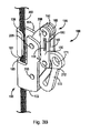
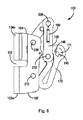
ケーブル移動器100の一実施形態の設計構造は、ケーブル300に適切に取り付けられるまでその使用を妨げるという特徴を含む。一実施形態において、ケーブル移動器100は、ケーブル移動器100が逆向きとされたとき(誤った向きとされたとき)、主アセンブリ196の形状を閉形態に保持するように設計されている。さらに、使用者が逆さに取り付ける前にケーブル移動器を開にすると、逆さ取付防止爪180は、ケーブル移動器が再び閉となることを防止する(すなわち、閉形態に置かれる)。さらに、取付アイ171は一部が閉鎖される(塞がれる)ので、落下防止システムをケーブル移動器に接続することができない。例えば、図5の組み立てられたケーブル移動器100の第2の側面図を参照すると、ケーブル移動器100(又は主アセンブリ196)が開形態にあるとき、第2のアームリンク140における延長ローブ部分(丸く突出した部分)146が、コントロールアーム170の取付アイ171を少なくとも部分的に遮蔽することが分かる。これにより、ケーブル移動器100がケーブル300に適切に取り付けられ、閉形態になるまで、落下防止システムのケーブル移動器100への取付けが防止される。また、図6の第1の側面図は、ケーブル移動器が開形態にあるときにコントロールアーム170の取付アイ171を少なくとも部分的に遮蔽する、第2のアームリンク140の遮蔽用ローブ部分146も示している。   The design structure of one embodiment of the cable mover 100 includes features that prevent its use until it is properly attached to the cable 300. In one embodiment, the cable mover 100 is designed to hold the shape of the main assembly 196 in a closed configuration when the cable mover 100 is reversed (incorrect orientation). Furthermore, if the cable mover is opened before the user installs upside down, the upside down prevention pawl 180 prevents the cable mover from closing again (ie, placed in a closed configuration). Further, since the mounting eye 171 is partially closed (closed), the fall prevention system cannot be connected to the cable mover. For example, referring to the second side view of the assembled cable mover 100 of FIG. 5, when the cable mover 100 (or main assembly 196) is in the open configuration, the extended lobe portion ( It can be seen that the round projecting portion 146 at least partially shields the mounting eye 171 of the control arm 170. This prevents the fall prevention system from being attached to the cable mover 100 until the cable mover 100 is properly attached to the cable 300 and is in the closed configuration. The first side view of FIG. 6 also shows a shielding lobe portion 146 of the second arm link 140 that at least partially shields the mounting eye 171 of the control arm 170 when the cable mover is in the open configuration. Show.

第1のカムアーム150のストッパ突起158に選択的に係合する逆さ取付防止爪180によって、ケーブル移動器100の開閉が選択的に制限される。ケーブル移動器100がケーブル300への取付けのための正しい向きにあるとき、爪180は、ストッパ突起158を避けるように重量がかけられ、ケーブル移動器100は開閉することができる。例えば、図7を参照すると、直立姿勢で提供されたケーブル移動器100が示されている。この図では、第1のアームリンク130は、ケーブルリンクがこの向きにあるときの浮動状態にある逆さ取付防止爪180の位置を示すために仮想線で示されている。図示されているように、この向きの逆さ取付防止爪180は、第2のアームリンク140に向かって指向するように重量がかけられ、第1のカムアーム150上のストッパ突起158から隙間を生じさせている。したがって、この形態にあるケーブル移動器100は自由に開くことができ(すなわち、ケーブル移動器100を開形態に自由に構成することができ)、これにより、ケーブル300は、図3A〜図3Cに関して上述したように、ケーブル移動器における上部及び下部ケーブルガイド通路103,105に挿入され得る。ここで図8を参照すると、逆向きにされたケーブル移動器100の図が示されている。ここでもまた、第1のアームリンク130は、逆さ取付防止爪180の位置状態を示すために仮想線で示されている。この逆向きでは、逆さ取付防止爪180の形状と重量により、逆さ取付防止爪180が第1のアームリンク130の方向に向けて配置されるようにする。この位置状態では、図示のように、逆さ取付防止爪180の一部が第1のカムアーム150のストッパ突起158と係合する。これにより、ケーブル移動器100が開とされることが防止される(開状態の向きに変わることが防止される)。したがって、ケーブル100を上部ケーブルガイド通路105内に配置することができず、それによって、逆方向のケーブル300にケーブル移動器が接続され始めることを防止することができる。   Opening and closing of the cable mover 100 is selectively restricted by the upside down prevention claws 180 that selectively engage with the stopper projections 158 of the first cam arm 150. When the cable mover 100 is in the correct orientation for attachment to the cable 300, the pawl 180 is weighted to avoid the stopper projection 158 and the cable mover 100 can be opened and closed. For example, referring to FIG. 7, a cable mover 100 provided in an upright position is shown. In this figure, the first arm link 130 is shown in phantom to indicate the position of the upside down prevention pawl 180 in a floating state when the cable link is in this orientation. As shown in the drawing, the inverted mounting prevention pawl 180 in this direction is weighted so as to be directed toward the second arm link 140, and creates a gap from the stopper projection 158 on the first cam arm 150. ing. Thus, the cable mover 100 in this configuration can be freely opened (i.e., the cable mover 100 can be freely configured in the open configuration), so that the cable 300 can be configured with respect to FIGS. As described above, it can be inserted into the upper and lower cable guide passages 103, 105 in the cable mover. Referring now to FIG. 8, a diagram of the cable mover 100 reversed is shown. Again, the first arm link 130 is shown in phantom lines to indicate the position of the upside down prevention pawl 180. In this reverse direction, the upside down prevention claws 180 are arranged toward the first arm link 130 due to the shape and weight of the upside down prevention claws 180. In this position state, as shown in the figure, a part of the upside down prevention claw 180 engages with the stopper projection 158 of the first cam arm 150. As a result, the cable mover 100 is prevented from being opened (prevented from changing to the open state). Accordingly, the cable 100 cannot be disposed in the upper cable guide passage 105, thereby preventing the cable mover from starting to be connected to the cable 300 in the reverse direction.

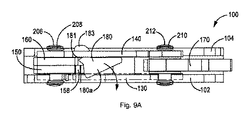
図9A及び図9Bの背面図には、ケーブル移動器100が開となるのを防止するための逆さ取付防止爪180の動作がさらに示されている。これらの図では、ケーブル移動器100は、逆向きに水平に配置されたところを示している。図9Aは、ケーブル移動器が最初に逆向きの水平位置に配置されるときの逆さ取付防止爪180の位置を示す。図9Bは、どうのようにして逆さ取付防止爪180の形状及び重量が逆さ取付防止爪180を第1のアーム130の第1のアーム受入れスロット135と第2のアームリンク140の第2のアーム受入れ通路145との中で摺動させ、それにより第1のカムアーム150のストッパ突起158の移動を防止する位置とされるかを示している。この構成では、第1及び第2のアームリンク130,140並びに第1及び第2のカムアーム150,160からなる主アセンブリ196(4つの構成要素及び4つの枢軸点)の動的平行四辺形構造は、リベット206,208,210,212により作られた4つの枢軸点を中心として枢動することができず、ケーブル移動器100を開形態に配置することができない。   The back view of FIGS. 9A and 9B further illustrates the operation of the upside down prevention pawl 180 to prevent the cable mover 100 from opening. In these drawings, the cable mover 100 is shown horizontally disposed in the opposite direction. FIG. 9A shows the position of the upside down prevention pawl 180 when the cable mover is initially placed in the reverse horizontal position. FIG. 9B shows how the shape and weight of the upside-down preventing claw 180 is reversed, and the upside-down preventing claw 180 is connected to the first arm receiving slot 135 of the first arm 130 and the second arm of the second arm link 140. It is shown whether or not the position of the stopper projection 158 of the first cam arm 150 is prevented from moving by sliding in the receiving passage 145. In this configuration, the dynamic parallelogram structure of the main assembly 196 (four components and four pivot points) comprising the first and second arm links 130, 140 and the first and second cam arms 150, 160 is , The four pivot points made by the rivets 206, 208, 210, 212 cannot be pivoted and the cable mover 100 cannot be placed in the open configuration.

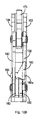
逆向きの垂直方向を向いたケーブル移動器100の背面図が、図10A及び図10Bに示されている。特に、図10A及び図10Bは、ケーブル移動器100が垂直に逆向きにされたときの逆さ取付防止爪180の動作を示している。図10Aは、ケーブル移動器100が最初に逆向きの垂直位置に配置されたときの逆さ取付防止爪180の位置を示す。図10Bは、逆さ取付防止爪180の重量と形状がどうのようにして逆さ取付防止爪180を第1のアーム130の第1のアーム受入れスロット135と第2のアームリンク140の第2のアーム受入れ通路145との中で摺動させ、それにより第1のカムアーム150のストッパ突起158の移動を防止する位置とされるかを示している。この構成では、第1及び第2のアームリンク130,140並びに第1及び第2のカムアーム150,160からなる主アセンブリ196(4つの構成要素及び4つの枢軸点)の動的平行四辺形構造は、リベット206,208,210,212により作られた4つの枢軸点を中心として枢動することができず、ケーブル移動器100を開形態に配置することができない。したがって、正しくない逆向きの水平方向又は垂直方向において、逆さ取付防止爪180は下降し第1のカムアーム150のストッパ突起158の通り道を横切るよう回転し、ケーブル移動器100が開とならないようにすると共に、ケーブル300に取り付けられないようにする。   A rear view of the cable mover 100 oriented in the opposite vertical direction is shown in FIGS. 10A and 10B. In particular, FIGS. 10A and 10B illustrate the operation of the upside down prevention pawl 180 when the cable mover 100 is vertically reversed. FIG. 10A shows the position of the upside down prevention pawl 180 when the cable mover 100 is initially placed in the reverse vertical position. FIG. 10B shows how the weight and shape of the upside-down preventing claw 180 is changed into the first arm receiving slot 135 of the first arm 130 and the second arm of the second arm link 140. It is shown whether or not the position of the stopper projection 158 of the first cam arm 150 is prevented from moving by sliding in the receiving passage 145. In this configuration, the dynamic parallelogram structure of the main assembly 196 (four components and four pivot points) comprising the first and second arm links 130, 140 and the first and second cam arms 150, 160 is , The four pivot points made by the rivets 206, 208, 210, 212 cannot be pivoted and the cable mover 100 cannot be placed in the open configuration. Therefore, in the incorrect reverse horizontal or vertical direction, the upside down prevention claw 180 descends and rotates across the path of the stopper projection 158 of the first cam arm 150 so that the cable mover 100 is not opened. At the same time, it is prevented from being attached to the cable 300.

さらに、このケーブル移動器100の設計構造では、ケーブル移動器100が正しい向きで開とされているが、逆向きに180度回転された場合、ケーブルは下部ケーブルガイド通路103及び上部ケーブルガイド通路105内に受け入れられ得るが、逆さ取付防止爪180の位置は、ストッパ突起158の他の側と係合して、ケーブル移動器100が閉形態に閉じられることを防止する。これは、ケーブル移動器100がケーブル300に適切に取り付けられていないことを使用者に明らかにする。   Further, in the design structure of the cable mover 100, the cable mover 100 is opened in the correct direction. However, when the cable mover 100 is rotated 180 degrees in the opposite direction, the cable is connected to the lower cable guide passage 103 and the upper cable guide passage 105. Although acceptable, the position of the upside down prevention pawl 180 engages the other side of the stopper projection 158 to prevent the cable mover 100 from being closed to the closed configuration. This reveals to the user that the cable mover 100 is not properly attached to the cable 300.

図11を参照すると、別の実施形態のケーブル移動器400が示されている。図11のケーブル移動器400は、閉位置にあるものとして示されている。開位置にあるケーブル移動器400の一例が図17に示されている。図12は、ケーブル移動器400の分解図を示す。ここで、ケーブル移動器400について、図11及び図12を参照して説明する。ケーブル移動器400は、ケーブル移動器400のハウジング495を構成する第1の本体プレート402及び第2の本体プレート404を含む。第1の本体プレート402及び第2の本体プレート404は、この実施形態では両方とも略L字形である。第1の本体プレート402は、第1の本体部分402a及び第2の本体部分402bを含む。第1の本体プレート402は、第1のプレート縁部402cと、その反対側の第2のプレート縁部402dとを有するものとしてさらに説明される。第2の本体プレート404はまた、第1の本体部分404aと、第2の本体部分404bと、第1のプレート縁部404cと、反対側の第2のプレート縁部404dとを含む。第1の本体プレート402の第1の本体部分402aは、上部接続開口407を含む。第1の本体プレート402の第2の本体部分402bは、第2のプレート縁部402dから延びて下部ケーブルガイド通路403を形成するC字形下部ガイド402eを含む。第1の本体プレート402の第2の本体部分402bは、下部接続開口411をさらに含む。第2の本体プレート404の第1の本体部分404aは、第2のプレート縁部404dから延びて上部ケーブルガイド通路405を形成するC字形上部ガイド404eを含む。第2の本体プレート404は、第2の本体プレート404の第1の本体部分404aに設けられた上部接続開口415と、第2の本体プレート404の第2の本体部分404bに設けられた下部接続開口417とを含む。   Referring to FIG. 11, another embodiment of a cable mover 400 is shown. The cable mover 400 of FIG. 11 is shown as being in the closed position. An example of a cable mover 400 in the open position is shown in FIG. FIG. 12 shows an exploded view of the cable mover 400. Here, the cable mover 400 will be described with reference to FIGS. 11 and 12. The cable mover 400 includes a first body plate 402 and a second body plate 404 that constitute a housing 495 of the cable mover 400. The first body plate 402 and the second body plate 404 are both substantially L-shaped in this embodiment. The first body plate 402 includes a first body portion 402a and a second body portion 402b. The first body plate 402 is further described as having a first plate edge 402c and a second plate edge 402d on the opposite side. The second body plate 404 also includes a first body portion 404a, a second body portion 404b, a first plate edge 404c, and an opposite second plate edge 404d. The first body portion 402 a of the first body plate 402 includes an upper connection opening 407. The second body portion 402b of the first body plate 402 includes a C-shaped lower guide 402e extending from the second plate edge 402d and forming a lower cable guide passage 403. The second body portion 402 b of the first body plate 402 further includes a lower connection opening 411. The first body portion 404a of the second body plate 404 includes a C-shaped upper guide 404e extending from the second plate edge 404d and forming an upper cable guide passage 405. The second body plate 404 includes an upper connection opening 415 provided in the first body portion 404 a of the second body plate 404 and a lower connection provided in the second body portion 404 b of the second body plate 404. And an opening 417.

この実施形態のケーブル移動器400は、第1のラベル420と、第2のラベル424とを含む。第1のラベル420は、第1のラベル開口421と、そこから離間した第2のラベル開口423とを含む。第1のラベル420は、第1のラベル開口421が上部接続開口407と整列し、第2のラベル開口423が第1の本体プレート402の下部接続開口411と整列するように、第1の本体プレート402に接着される。第2のラベル424は、第1のラベル開口425と、そこから離間した第2のラベル開口426とを含む。第2のラベル424は、第1のラベル開口425が上部接続開口415と整列し、第2のラベル開口426が第2の本体プレート404の下部接続開口417と整列するように、第2の本体プレート404に接着される。   The cable mover 400 of this embodiment includes a first label 420 and a second label 424. The first label 420 includes a first label opening 421 and a second label opening 423 spaced therefrom. The first label 420 has a first body such that the first label opening 421 is aligned with the upper connection opening 407 and the second label opening 423 is aligned with the lower connection opening 411 of the first body plate 402. Bonded to the plate 402. The second label 424 includes a first label opening 425 and a second label opening 426 spaced therefrom. The second label 424 includes a second body such that the first label opening 425 is aligned with the upper connection opening 415 and the second label opening 426 is aligned with the lower connection opening 417 of the second body plate 404. Bonded to the plate 404.

ケーブル移動器400は、第1のアームリンク430と、第2のアームリンク440とをさらに含む。第1のアームリンク430は、第1の端部分430aと、その反対側の第2の端部分430bとを含む。第1の端部分430aは、細長い中間部分430cを介して第2の端部分430bから離間している。第1のアームリンク430の第1の端部分430aは第1のアーム開口431を含み、第1のアームリンク430の第2の端部分430bは第2のアーム開口433を含む。第1のアームリンク430の中間部分430cは、第1のアーム受入れスロット435を含む。第1のアーム受入れスロット435と第1のアーム開口431との間には、付勢端保持用開口437が配置されている。一実施形態では、第1のアームリンク430の第1の端部部430a及び第2の端部分430bの両方が丸みの付けらたれ縁部で終端している。   The cable mover 400 further includes a first arm link 430 and a second arm link 440. The first arm link 430 includes a first end portion 430a and an opposite second end portion 430b. The first end portion 430a is spaced from the second end portion 430b via an elongated intermediate portion 430c. The first end portion 430 a of the first arm link 430 includes a first arm opening 431, and the second end portion 430 b of the first arm link 430 includes a second arm opening 433. The intermediate portion 430 c of the first arm link 430 includes a first arm receiving slot 435. A biasing end holding opening 437 is disposed between the first arm receiving slot 435 and the first arm opening 431. In one embodiment, both the first end 430a and the second end portion 430b of the first arm link 430 terminate at a rounded edge.

第2のアームリンク440は、第1の端部分440aと、その反対側の第2の端部分440bとを含む。第1の端部分440aは、細長い中間部分440cを介して第2の端部分440bから離間している。第2のアームリンク440の第1の端部分440aは第1のアーム開口441を含み、第2のアームリンク440の第2の端部分440bは第2のアーム開口443を含む。中間部分440cは、第2のアームリンク440の第1の端部分440a近傍に第2のアーム受入れ通路445を含む。一実施形態では、第2のアームリンク440の第1の端部分440a及び第2の端部分440bの両方は、丸みの付けられた縁部で終端している。   The second arm link 440 includes a first end portion 440a and an opposite second end portion 440b. The first end portion 440a is spaced from the second end portion 440b via an elongated intermediate portion 440c. The first end portion 440 a of the second arm link 440 includes a first arm opening 441, and the second end portion 440 b of the second arm link 440 includes a second arm opening 443. The intermediate portion 440 c includes a second arm receiving passage 445 in the vicinity of the first end portion 440 a of the second arm link 440. In one embodiment, both the first end portion 440a and the second end portion 440b of the second arm link 440 terminate at a rounded edge.

ケーブル移動器400はまた、第1のカムアーム450と、第2のカムアーム460とを含む。第1のカムアーム450は、丸みの付けられた縁部で終端する第1の端部分450aと、丸みの付けられた縁部で終端する、反対側の第2の端部部分450bとを含む。第1の端部分450aと第2の端部分450bとの間には、細長い中間部分450cがある。第1のカムアーム450は、第1の縁部450dと、その反対側の第2の縁部450eとをさらに含む。第1の縁部450d及び第2の縁部450eは、第1の端部分450aと第2の端部分450bとの間で延びている。第1のカムアーム450の第1の縁部450dは、中間部分450cに近接した切欠き部456を含む。第1のカムアーム450は、第2の端部分450bの近くで第1の縁部450dから外向きに延びるストッパ突起458をさらに有する。第1のカムアーム450は、第1の端部分450aに設けられた第1の開口451と、第1の端部分450aの近傍の、中間部分450cにある第2の開口453と、第2の端部分450bの近傍の、中間部分450cにある第3の開口457と、第2の端部分450bに設けられた第4の開口459とを含む。   The cable mover 400 also includes a first cam arm 450 and a second cam arm 460. The first cam arm 450 includes a first end portion 450a that terminates at a rounded edge and an opposite second end portion 450b that terminates at a rounded edge. Between the first end portion 450a and the second end portion 450b is an elongated intermediate portion 450c. The first cam arm 450 further includes a first edge 450d and a second edge 450e opposite to the first edge 450d. The first edge portion 450d and the second edge portion 450e extend between the first end portion 450a and the second end portion 450b. The first edge 450d of the first cam arm 450 includes a notch 456 proximate to the intermediate portion 450c. The first cam arm 450 further includes a stopper projection 458 extending outward from the first edge 450d near the second end portion 450b. The first cam arm 450 includes a first opening 451 provided in the first end portion 450a, a second opening 453 in the intermediate portion 450c in the vicinity of the first end portion 450a, and a second end. It includes a third opening 457 in the intermediate portion 450c in the vicinity of the portion 450b and a fourth opening 459 provided in the second end portion 450b.

第2のカムアーム460は、丸みの付けられた縁部で終端する第1の端部分460aと、丸みの付けられた縁部で終端する反対側の第2の端部分460bとを含む。第1の端部分460aと第2の端部分460bとの間には、細長い中間部分460cがある。第2のカムアーム460は、第1の端部分460aに設けられた第1の開口462と、第1の端部分460aの近傍の、中間部分460cにある第2の開口461と、第2の端部分460bの近傍の、中間部分460cにある第3の開口463と、第2の端部分460bに設けられた第4の開口465と、第3の開口463の近傍に配置された付勢端保持用開口467とを含む。第2のカムアーム460の第1の開口は、第1のカムアーム450の第1の開口451と整列される。   The second cam arm 460 includes a first end portion 460a that terminates at a rounded edge and an opposite second end portion 460b that terminates at a rounded edge. Between the first end portion 460a and the second end portion 460b is an elongated intermediate portion 460c. The second cam arm 460 includes a first opening 462 provided in the first end portion 460a, a second opening 461 in the intermediate portion 460c in the vicinity of the first end portion 460a, and a second end. A third opening 463 in the intermediate portion 460c in the vicinity of the portion 460b, a fourth opening 465 provided in the second end portion 460b, and a biased end holding disposed in the vicinity of the third opening 463 Opening 467. The first opening of the second cam arm 460 is aligned with the first opening 451 of the first cam arm 450.

ケーブル移動器400はまた、コントロールアーム470を含む。コントロールアーム470は、この実施形態では、エネルギーを吸収する変形可能な細長い部材から作られている。コントロールアーム470は、取付アイ471を有する第1の端部分472aと、第1の開口474を有する第2の端部分472bとを含む。コントロールアーム470は、第1のアーム部分470aと、第2のアーム部分470bと、第3のアーム部分470cとをさらに含み、これらのアーム部分は初期状態で互いに接近して折り畳まれる。落下中、第1のアーム部分470a、第2のアーム部分470b及び第3のアーム部分470cは、互いに関して真っ直ぐな状態になってエネルギーを吸収する。この実施形態では、第1のアーム部分470aにおける第1の端部分472aの第1の面部分473aは、第2のアーム部分470bにおける第2の面部分473bと係合する。第1のアーム部分470aの第1の面部分473aと第2のアーム部分470bの第2の面部分473bとの係合を解除するには、ある選択された大きさの力が必要である。また、この実施形態では、第2のアーム部470bの第1の面部分475aが第3のアーム部分470cの第2の面部分475bに係合している。第2のアーム部分470bの第1の面部分475aを第3のアーム部分470cの第2の面部分475bから外すには、ある選択された大きさの力が必要である。コントロールアーム470は、第2のアーム部分470b及び第3のアーム部分470cの近傍にある第2の開口476をさらに含む。   Cable mover 400 also includes a control arm 470. The control arm 470 is made of a deformable elongate member that absorbs energy in this embodiment. Control arm 470 includes a first end portion 472 a having a mounting eye 471 and a second end portion 472 b having a first opening 474. The control arm 470 further includes a first arm portion 470a, a second arm portion 470b, and a third arm portion 470c, which are folded close to each other in the initial state. During the fall, the first arm portion 470a, the second arm portion 470b, and the third arm portion 470c are straight with respect to each other to absorb energy. In this embodiment, the first surface portion 473a of the first end portion 472a in the first arm portion 470a engages the second surface portion 473b in the second arm portion 470b. A force of a selected magnitude is required to disengage the first surface portion 473a of the first arm portion 470a and the second surface portion 473b of the second arm portion 470b. In this embodiment, the first surface portion 475a of the second arm portion 470b is engaged with the second surface portion 475b of the third arm portion 470c. A selected amount of force is required to disengage the first surface portion 475a of the second arm portion 470b from the second surface portion 475b of the third arm portion 470c. The control arm 470 further includes a second opening 476 in the vicinity of the second arm portion 470b and the third arm portion 470c.

さらに、ケーブル移動器400は逆さ取付防止爪480を含む。逆さ取付防止爪480は、一実施形態では、略三角形の形状をしたベース部分480aと、ベース部分480aから延びるキャッチ部分480bとを含む。キャッチ部分480bは、第1のストッパ壁482と、そこから離間した第2のストップパ483とを含み、これらの間にキャッチ領域481が形成されている。また、ケーブル移動器400には、第1の端部490a、第2の端部490b及びコイル状部分490cを有する付勢部材490が含まれる。この実施形態では、プランジャアセンブリ600も含まれる。プランジャアセンブリ600は、ケーブル移動器400に対して追加の安全機能を提供する。プランジャアセンブリ600は、以下でさらに詳細に説明するように、プランジャアセンブリ600を操作することなく、ケーブル移動器400が開形態に配置されることを防止するように設計されている。プランジャアセンブリ600は、管状の主要部分606a及び延長アームストッパ606bを有するプランジャ606を含む。延長アームストッパ606bは、主要部分606aの端部から延びている。延長アームストッパ606bは、第1の本体プレート402の第1の本体部分402aを貫通して延びるストッパスロット通路611内に受け入れられる。プランジャアセンブリ600は、取付ロッド602をさらに含む。取付ロッド602は、ヘッド端部602aと、中間部分602bと、第2の端部分602cとを含む。第2の端部分602cは、第1の本体プレート402における第1の本体部分402aに、ストッパスロット通路611の近傍に設けられたプランジャ開口613内に受け入れられる。取付ロッド602の第2の端部分602cの終端部に結合された保持キャップ602dは、取付ロッド602を第1の本体プレート402に結合する。プランジャ606の主要部分606aは、より小さなロッド通路(図示せず)に通じる付勢キャビティ607をさらに含む。取付ロッド602の少なくとも中間部分602bはプランジャ606の付勢キャビティ607内に受け入れられ、取付ロッド602はより小さなロッド通路に挿通される。付勢部材604は、取付ロッド602の中間部分602bの周りに配置され、且つプランジャ606の付勢キャビティ607内に受け入れられる。付勢部材604は、取付ロッド602のヘッド端部602aに係合する第1の端部を有する。付勢部材604は、プランジャ606の付勢キャビティ607の内面(図示せず)と係合する第2の端部を有する。このように配置された付勢部材604は、プランジャ606に付勢力を加え、延長アームストッパ606bを第1の本体プレート402のストッパスロット通路611内へと押し込む。延長アームストッパ606bは、第1の本体プレート402のストッパスロット通路611を通って延びているとき、第1のアームカム450の移動を制限する。これにより、以下で詳細に説明する安全機能が与えられる。   Further, the cable mover 400 includes an upside down mounting prevention claw 480. The upside down prevention pawl 480 includes a base portion 480a having a substantially triangular shape and a catch portion 480b extending from the base portion 480a in one embodiment. The catch portion 480b includes a first stopper wall 482 and a second stop pad 483 spaced from the first stopper wall 482, and a catch region 481 is formed therebetween. The cable mover 400 also includes a biasing member 490 having a first end 490a, a second end 490b, and a coiled portion 490c. In this embodiment, a plunger assembly 600 is also included. Plunger assembly 600 provides additional safety features for cable mover 400. The plunger assembly 600 is designed to prevent the cable mover 400 from being placed in the open configuration without manipulating the plunger assembly 600, as described in more detail below. Plunger assembly 600 includes a plunger 606 having a tubular main portion 606a and an extended arm stopper 606b. The extension arm stopper 606b extends from the end of the main portion 606a. The extension arm stopper 606b is received in a stopper slot passage 611 extending through the first body portion 402a of the first body plate 402. Plunger assembly 600 further includes a mounting rod 602. The mounting rod 602 includes a head end 602a, an intermediate portion 602b, and a second end portion 602c. The second end portion 602 c is received in a plunger opening 613 provided in the vicinity of the stopper slot passage 611 in the first body portion 402 a of the first body plate 402. A retaining cap 602 d coupled to the terminal end of the second end portion 602 c of the mounting rod 602 couples the mounting rod 602 to the first body plate 402. The main portion 606a of the plunger 606 further includes a biasing cavity 607 that leads to a smaller rod passage (not shown). At least an intermediate portion 602b of the mounting rod 602 is received within the biasing cavity 607 of the plunger 606, and the mounting rod 602 is inserted through a smaller rod passage. The biasing member 604 is disposed around the intermediate portion 602 b of the mounting rod 602 and is received in the biasing cavity 607 of the plunger 606. The biasing member 604 has a first end that engages the head end 602 a of the mounting rod 602. The biasing member 604 has a second end that engages the inner surface (not shown) of the biasing cavity 607 of the plunger 606. The biasing member 604 arranged in this manner applies a biasing force to the plunger 606 and pushes the extension arm stopper 606 b into the stopper slot passage 611 of the first main body plate 402. The extension arm stopper 606b restricts the movement of the first arm cam 450 when extending through the stopper slot passage 611 of the first body plate 402. This gives the safety function described in detail below.

ここで、ケーブル移動器400の構成要素の接続について説明する。第1のカムアーム450の第1の開口451及び第2のカムアーム460の第1の開口462内に受け入れられた第1のリベットピン502と、第1のカムアーム450の第3の開口457及び第2のカムアーム460の第3の開口463内に受け入れられた第2のリベットピン504が、第1のカムアーム450を第2のカムアーム460に機能的に結合する。第1の直径を持つ中央部分506aを有する第1のリベット506が、第1のカムアーム450の第2の開口453及び第2のカムアーム460の第2の開口461内に受け入れられる。より小さな第2の直径を持つ第1のリベット506の第1の端部分506bは、第1の本体プレート402の上部接続開口407及び第1のラベル420の第1のラベル開口421内に受け入れられる。第1のワッシャ521が、第1の本体プレート402と第1のカムアーム450との間にて第1のリベット506の第1の端部分506bの周囲に配置される。より小さな第2の直径を持つ第1のリベット506の第2の端部分506cは、第2の本体プレート404の上部接続開口415及び第2のラベル424の第2のラベル開口425内に受け入れられる。第2のワッシャ522は、第2の本体プレート404と第2のカムアーム460との間にて第1のリベット506の第2の端部分506cの周りに配置される。   Here, the connection of the components of the cable mover 400 will be described. The first rivet pin 502 received in the first opening 451 of the first cam arm 450 and the first opening 462 of the second cam arm 460, and the third opening 457 and the second of the first cam arm 450. A second rivet pin 504 received in the third opening 463 of the second cam arm 460 operably couples the first cam arm 450 to the second cam arm 460. A first rivet 506 having a central portion 506 a having a first diameter is received within the second opening 453 of the first cam arm 450 and the second opening 461 of the second cam arm 460. The first end portion 506b of the first rivet 506 having a smaller second diameter is received within the upper connection opening 407 of the first body plate 402 and the first label opening 421 of the first label 420. . A first washer 521 is disposed around the first end portion 506 b of the first rivet 506 between the first body plate 402 and the first cam arm 450. A second end portion 506c of the first rivet 506 having a smaller second diameter is received within the upper connection opening 415 of the second body plate 404 and the second label opening 425 of the second label 424. . The second washer 522 is disposed around the second end portion 506 c of the first rivet 506 between the second body plate 404 and the second cam arm 460.

第1の直径の中央部分510aを有する第2のリベット510は、第1のカム450の第4の開口459及び第2のカム460の第4の開口465内に受け入れられる。より小さな第2の直径を有する第2のリベット510の第1の端部510bは、第1のアームリンク430の第1のアーム開口431内に受け入れられ、より小さな第2の直径を有する第2のリベット510の第2の端部510cは、第2のアームリンク440のアーム開口441内に受け入れられる。付勢部材490のコイル状部分490cは、第2のリベット510の中央部分510aの周りに配置され、且つ第1のカムアーム450の第4の開口459内に受け入れられる。さらに、付勢部材490の第1の端部490aは、第1のアームリンク430の付勢端保持用開口437内に受け入れられ、付勢部材490の第2の端部490bは、第2のカムアーム460の付勢端保持用開口467内に受け入れられる。付勢部材490の位置が図17にさらに示されている。一実施形態では、付勢部材は、ケーブル650に係合するように、第1及び第2のカムアーム450,460に付勢力を加えるように配置される。   A second rivet 510 having a first diameter central portion 510 a is received within the fourth opening 459 of the first cam 450 and the fourth opening 465 of the second cam 460. A first end 510b of a second rivet 510 having a smaller second diameter is received within the first arm opening 431 of the first arm link 430 and a second having a smaller second diameter. The second end 510 c of the rivet 510 is received in the arm opening 441 of the second arm link 440. The coiled portion 490 c of the biasing member 490 is disposed around the central portion 510 a of the second rivet 510 and is received within the fourth opening 459 of the first cam arm 450. Further, the first end portion 490a of the biasing member 490 is received in the biasing end holding opening 437 of the first arm link 430, and the second end portion 490b of the biasing member 490 is the second end portion 490b. The cam arm 460 is received in the biasing end holding opening 467. The position of the biasing member 490 is further shown in FIG. In one embodiment, the biasing member is arranged to apply a biasing force to the first and second cam arms 450, 460 to engage the cable 650.

図12を再び参照すると、第3のリベット508の、第1の直径を有する中央部分508aはコントロールアーム470の第1の開口474内に受け入れられる。より小さな第2の直径を有する第3のリベット508の第1の端部分508bは、第1の本体プレート402の下部接続開口411及び第1のラベル421の第2のラベル開口423内に受け入れられる。第1の本体プレート402とコントロールアーム470との間にて第3のリベット508の第1の端部分508bの周囲には、第3、第4及び第5のワッシャ524a,524b,524cが配置される。より小さな第2の直径を有する第3のリベット508の第2の端部分508cは、第2の本体プレート404の下部接続開口417及び第2のラベル424の第2のラベル開口426内に受け入れられる。第6、第7及び第8のワッシャ526a,526b,526cは、第2本体プレート404とコントロールアーム470との間にて第2リベット508の第2の端部分508cの周囲に配置される。   Referring again to FIG. 12, the central portion 508 a having the first diameter of the third rivet 508 is received within the first opening 474 of the control arm 470. The first end portion 508b of the third rivet 508 having a smaller second diameter is received within the lower connection opening 411 of the first body plate 402 and the second label opening 423 of the first label 421. . Around the first end portion 508b of the third rivet 508 between the first body plate 402 and the control arm 470, third, fourth and fifth washers 524a, 524b, 524c are arranged. The A second end portion 508c of the third rivet 508 having a smaller second diameter is received within the lower connection opening 417 of the second body plate 404 and the second label opening 426 of the second label 424. . The sixth, seventh and eighth washers 526a, 526b, 526c are disposed around the second end portion 508c of the second rivet 508 between the second body plate 404 and the control arm 470.

第1の直径を持つ中央部分512aを有する第4のリベット512は、コントロールアーム470の第2の開口476内に受け入れられる。第1の直径よりも小さな第2の直径を有する第4のリベット512の第1の端部分512bは、第1のアームリンク430の第2のアーム開口433内に受け入れられる。第9のワッシャ528a及び第10のワッシャ528bは、第1のアームリンク430とコントロールアーム470との間にて第4のリベット512の第1の端部分512bの周りに配置される。より小さな第2の直径を有する第4のリベット512の第2の端部分512cは、第2のアームリンク440の第2のアーム開口443内に受け入れられる。第11のワッシャ530a及び第12のワッシャ530bは、第2のアームリンク440とコントロールアーム470との間にて第4のリベット512の第2の端部分512cの周りに配置される。逆さ取付防止爪480は、第1のアームリンク430の第1のアーム受入れスロット435及び第2のアームリンク440の第2のアーム受入れ通路445内に摺動可能に保持される。具体的には、逆さ取付防止爪480のベース部分480aの一部が第1のアームリンク430の第1のアーム受入れスロット435内に摺動可能に受け入れられ、逆さ取付防止爪480のキャッチ部分480bが第2のアームリンク440の第2のアーム受入れ通路445内に摺動可能に受け入れられる。一実施形態においては、ストッパ壁482,483の少なくとも一方が、第2のアームリンク440の第2のアーム受入れ通路445内に逆さ取付防止爪480のキャッチ部分480bを保持する。   A fourth rivet 512 having a central portion 512 a having a first diameter is received within the second opening 476 of the control arm 470. A first end portion 512b of the fourth rivet 512 having a second diameter that is smaller than the first diameter is received in the second arm opening 433 of the first arm link 430. A ninth washer 528 a and a tenth washer 528 b are disposed around the first end portion 512 b of the fourth rivet 512 between the first arm link 430 and the control arm 470. A second end portion 512 c of the fourth rivet 512 having a smaller second diameter is received within the second arm opening 443 of the second arm link 440. The eleventh washer 530a and the twelfth washer 530b are disposed around the second end portion 512c of the fourth rivet 512 between the second arm link 440 and the control arm 470. The upside down prevention claw 480 is slidably held in the first arm receiving slot 435 of the first arm link 430 and the second arm receiving passage 445 of the second arm link 440. Specifically, a part of the base portion 480a of the upside down attachment preventing claw 480 is slidably received in the first arm receiving slot 435 of the first arm link 430, and the catch portion 480b of the upside down attachment preventing claw 480 is provided. Is slidably received in the second arm receiving passage 445 of the second arm link 440. In one embodiment, at least one of the stopper walls 482, 483 holds the catch portion 480 b of the upside down prevention pawl 480 within the second arm receiving passage 445 of the second arm link 440.

ケーブル移動器400は、動的平行四辺形構造(4つの構成要素及び4つの枢軸点)を有する主アセンブリ496を有するように設計されている。主アセンブリ496を構成する4つの構成要素は、第1及び第2のアームリンク430,440並びに第1及び第2のカムアーム450,460を含む。4つの枢軸点は、リベット506,508,510,512によって形成される。ケーブル移動器400は、互いに対向する平行構成要素(第1及び第2のアームリンク430,440並びに第1及び第2のカムアーム450,460)が互いに最も近いときに閉形態となり、対向する平行構成要素(第1及び第2アームリンク430,440並びに第1及び第2カムアーム450,460)が互いに最も離れているときに開形態となる。   The cable mover 400 is designed to have a main assembly 496 having a dynamic parallelogram structure (4 components and 4 pivot points). The four components that make up the main assembly 496 include first and second arm links 430, 440 and first and second cam arms 450, 460. The four pivot points are formed by rivets 506, 508, 510, 512. The cable mover 400 is closed when the parallel components facing each other (the first and second arm links 430 and 440 and the first and second cam arms 450 and 460) are closest to each other. The open configuration occurs when the elements (first and second arm links 430, 440 and first and second cam arms 450, 460) are farthest from each other.

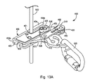
正しい向きでケーブル移動器400をケーブル650に係合させる例が、図13A〜図13Cに示されている。図13Aにおいて、ケーブル移動器400は開形態にある。開形態は、ケーブル移動器400をケーブル650に取り付けるときに使用される。この形態では、第1及び第2のカムアーム450,460のそれぞれの第1の端部分450a,460aは、第1の本体プレート402及び第2の本体プレート404によって形成された下部ケーブルガイド通路403及び上部ケーブルガイド通路405へのアクセス領域から離れるように移動される。図13Aに示すように、ケーブル移動器400は、ケーブル650が第2の本体プレート404の上部ガイド404eと第1の本体プレート402の下部ガイド402eとの間に配置されたケーブル挿入通路401に受け入れられるように傾けられる。この例では、上部ガイド404eによって形成される上部ケーブルガイド通路405へのアクセス経路が上方を向いている。この位置において、ケーブル移動器400をケーブル650に正しく取り付けることができる。さらに、開形態では、プランジャ606は、第1の本体プレート402に対して外側に引っ張られ、付勢部材604の付勢力に対抗して、プランジャ606の延長アームストッパ606bが第1のカムアームの縁部450との係合を解除されるようにする。   Examples of engaging cable mover 400 with cable 650 in the correct orientation are shown in FIGS. 13A-13C. In FIG. 13A, cable mover 400 is in an open configuration. The open configuration is used when attaching the cable mover 400 to the cable 650. In this configuration, the first end portions 450a, 460a of the first and second cam arms 450, 460 respectively have a lower cable guide passage 403 formed by the first body plate 402 and the second body plate 404 and It is moved away from the access area to the upper cable guide passage 405. As shown in FIG. 13A, the cable mover 400 receives a cable 650 in a cable insertion passage 401 disposed between the upper guide 404e of the second body plate 404 and the lower guide 402e of the first body plate 402. Tilt as you can. In this example, the access path to the upper cable guide passage 405 formed by the upper guide 404e faces upward. In this position, the cable mover 400 can be correctly attached to the cable 650. Furthermore, in the open configuration, the plunger 606 is pulled outward with respect to the first body plate 402, and the extension arm stopper 606 b of the plunger 606 opposes the urging force of the urging member 604 so that the edge of the first cam arm The engagement with the part 450 is released.

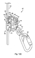
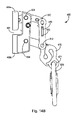
図13Bは、ケーブル650が第1の本体プレート402の下部ケーブルガイド通路403と第2の本体プレート404の上部ケーブルガイド通路405に入るように、ケーブル移動器400が回されることを示している。図13Bでは、ケーブル移動器400は開形態にあり、プランジャ606が第1の本体プレート402に対して引き出された位置にある状態となっている。これは、第1のカムアーム450の中間部分の表面に係合するプランジャ606の延長アームストッパ606bによって引き起こされる。図13Cは、ケーブル650に係合するためのケーブル移動器400の動作を示す。さらに、図3Cは、閉形態のケーブル移動器400を示す。この形態では、第1のカムアーム450の第1の端部分450a及び第2のカムアーム460の第1の端部分460aは、ハウジング495の上部ガイド404e内においてケーブル650と係合する。さらに、この形態では、コントロールアーム470の第2の端部分472bは、ハウジング495の下部ガイド402e内においてケーブル650と係合する。次いで、落下防止システムを、コントロールアーム470の取付アイ471に取り付けられたカラビナ520に取り付けることができる。落下事故が発生すると、コントロールアーム470の力は、第1のカムアーム450の第1の端部分450a及び第2のカムアーム460の第1の端部分460a並びにコントロールアーム470の第2の端部分472bをケーブル650に押圧し、落下を阻止する。図13Cに示すように、プランジャ606はもはや引き出された位置にはない。第1のアームカム450が移動されているので、付勢部材604は第1の本体プレート402のストッパスロット通路611を通して延長アームストッパ606bを自由に押圧することができる。この位置において、延長アームストッパ606bは、第1のアームカム450の動きを制限し、ケーブル移動器400を開いた形態に配置することができず、ケーブル650からのケーブル移動器400の偶発的な脱落を防止する。   FIG. 13B shows that the cable mover 400 is turned so that the cable 650 enters the lower cable guide passage 403 of the first body plate 402 and the upper cable guide passage 405 of the second body plate 404. . In FIG. 13B, the cable mover 400 is in the open configuration, with the plunger 606 in a position withdrawn relative to the first body plate 402. This is caused by the extension arm stopper 606b of the plunger 606 that engages the surface of the intermediate portion of the first cam arm 450. FIG. 13C illustrates the operation of the cable mover 400 to engage the cable 650. In addition, FIG. 3C shows a cable mover 400 in a closed configuration. In this configuration, the first end portion 450a of the first cam arm 450 and the first end portion 460a of the second cam arm 460 engage the cable 650 within the upper guide 404e of the housing 495. Further, in this configuration, the second end portion 472b of the control arm 470 engages the cable 650 within the lower guide 402e of the housing 495. The fall prevention system can then be attached to the carabiner 520 attached to the attachment eye 471 of the control arm 470. When a fall accident occurs, the force of the control arm 470 acts on the first end portion 450a of the first cam arm 450, the first end portion 460a of the second cam arm 460, and the second end portion 472b of the control arm 470. The cable 650 is pressed to prevent the fall. As shown in FIG. 13C, the plunger 606 is no longer in the extended position. Since the first arm cam 450 is moved, the urging member 604 can freely press the extension arm stopper 606 b through the stopper slot passage 611 of the first main body plate 402. In this position, the extension arm stopper 606b limits the movement of the first arm cam 450, the cable mover 400 cannot be placed in the open configuration, and the cable mover 400 is accidentally dropped from the cable 650. To prevent.

図14A及び図14Bは、ケーブル移動器400及びカラビナ520の異なる図をさらに示す。特に、図14Aはケーブル移動器400の背面図であり、図14Bは閉形態のケーブル移動器400の第1の側面図である。上述したように、カラビナ520は、使用者に接続された落下停止システムに結合される。図15は、開形態のケーブル移動器400の第2の側面図を示す。さらに図16は、開形態のケーブル移動器400の第1の側面図を示す。   14A and 14B further illustrate different views of cable mover 400 and carabiner 520. FIG. In particular, FIG. 14A is a rear view of the cable mover 400, and FIG. 14B is a first side view of the cable mover 400 in a closed configuration. As described above, the carabiner 520 is coupled to a fall stop system connected to the user. FIG. 15 shows a second side view of the cable mover 400 in the open configuration. Further, FIG. 16 shows a first side view of the cable mover 400 in the open configuration.

ケーブル移動器400の色々な設計構造の実施形態は、ケーブル650に適切に取り付けられるまでその使用を妨げる機能を含む。一実施形態において、ケーブル移動器400は、ケーブル移動器400が逆向きとされたとき(誤った向きとされたとき)、閉形態で主アセンブリ496の形状を固定するように設計されている。さらに、使用者がケーブル移動器400を逆さに取り付ける前に開いた状態にした場合、逆さ取付防止爪480は、ケーブル移動器400が再閉鎖することを防止する(すなわち、閉形態に配置されることを防止する)。さらに、上述のようなこの実施形態では、延長アームストップ606bは第1のアームカム450の移動を制限し、追加的な安全機能のために、プランジャアセンブリ600のプランジャ606を引き出すことなく、ケーブル移動器400を閉形態から開形態に変更することができないようにする。   Various design structure embodiments of the cable mover 400 include features that prevent its use until it is properly attached to the cable 650. In one embodiment, the cable mover 400 is designed to fix the shape of the main assembly 496 in the closed configuration when the cable mover 400 is reversed (in the wrong direction). Furthermore, if the user opens the cable mover 400 before attaching it upside down, the upside down prevention pawl 480 prevents the cable mover 400 from reclosing (ie, placed in a closed configuration). To prevent this). Further, in this embodiment as described above, the extension arm stop 606b limits the movement of the first arm cam 450, and without additional withdrawal of the plunger 606 of the plunger assembly 600 for additional safety functions. 400 cannot be changed from the closed configuration to the open configuration.

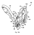
この実施形態において、ケーブル移動器400の開閉は、逆さ取付防止爪480及びプランジャアセンブリ600のプランジャ606によって選択的に制限される。逆さ取付防止爪480は、第1のカムアーム450のストッパ突起458に選択的に係合する。ケーブル移動器400がケーブル650に取り付けるための正しい向きにあるとき、逆さ取付防止爪480は、ストッパ突起458を回避するように重量がかけられ、プランジャ606が引き戻されればケーブル移動器400を開閉することができる。例えば、図17Aを参照すると、直立位置で示されたケーブル移動器400が与えられている。この図では、ケーブルリンクがこの向きにあるとき浮動状態の逆さ取付防止爪480の位置を示すために、第1のアームリンク430は仮想線で示されている。図示されているように、この向きの逆さ取付防止爪480は、第2のアームリンク440に向かって配置されるように重量がかけられ、第1のカムアーム450のストッパ突起458から隙間を形成する。したがって、この向きのケーブル移動器400は、(プランジャ606が引き戻されていれば)自由に開くことができ、図13A〜図13Cに関して上述したように、ケーブル650をケーブル移動器400の上下のケーブルガイド通路405,403に挿入することを可能とする。ここで図18Aを参照すると、逆向きとされたケーブル移動器400の図が示されている。ここでも、第1アームリンク430は、逆さ取付防止爪480の位置を示すために仮想線で示されている。この逆向きでは、逆さ取付防止爪480の重量によって、逆さ取付防止爪480は第1のアームリンク430に向けて配置されることになる。この位置では、図示されるように、逆さ取付防止爪480の一部は、第1のカムアーム450のストッパ突起458と係合する。これにより、ケーブル移動器400が開かれることが防止される(開いた向きに変更されることが防止される)。したがって、ケーブル650を上部ケーブルガイド通路405内に配置することができず、ケーブル移動器400が逆向きにケーブル650に連結されることが防止される。また。ストッパ突起458は、逆向きとされたとき既に開いた形態にあるときにケーブル移動器400が、逆向きとされたまま閉形態に移行されるのを防止する。   In this embodiment, opening and closing of the cable mover 400 is selectively limited by the upside down prevention pawl 480 and the plunger 606 of the plunger assembly 600. The inverted attachment preventing claw 480 selectively engages with the stopper projection 458 of the first cam arm 450. When the cable mover 400 is in the correct orientation for attachment to the cable 650, the upside down prevention pawl 480 is weighted to avoid the stopper projection 458 and opens and closes the cable mover 400 when the plunger 606 is pulled back. be able to. For example, referring to FIG. 17A, a cable mover 400 is provided shown in an upright position. In this figure, the first arm link 430 is shown in phantom to show the position of the upside down attachment prevention pawl 480 when the cable link is in this orientation. As shown in the drawing, the inverted mounting prevention pawl 480 in this direction is weighted so as to be arranged toward the second arm link 440 and forms a gap from the stopper projection 458 of the first cam arm 450. . Thus, the cable mover 400 in this orientation is free to open (if the plunger 606 is pulled back), and the cable 650 is connected to the upper and lower cables of the cable mover 400 as described above with respect to FIGS. 13A-13C. It can be inserted into the guide passages 405 and 403. Referring now to FIG. 18A, a diagram of the cable mover 400 being reversed is shown. Again, the first arm link 430 is shown in phantom lines to indicate the position of the upside down prevention claws 480. In this reverse direction, the inverted attachment preventing claw 480 is arranged toward the first arm link 430 due to the weight of the inverted attachment preventing claw 480. In this position, as shown in the drawing, a part of the upside down prevention claw 480 engages with the stopper projection 458 of the first cam arm 450. As a result, the cable mover 400 is prevented from being opened (prevented from being changed to the open orientation). Therefore, the cable 650 cannot be disposed in the upper cable guide passage 405, and the cable mover 400 is prevented from being connected to the cable 650 in the reverse direction. Also. The stopper projection 458 prevents the cable mover 400 from being moved to the closed configuration while being in the reverse orientation when it is already in the open configuration when the orientation is reversed.

図17B及び図18Bは、逆さ取付防止爪の別の構成を有するケーブル移動器700の他の実施形態を示す。この実施形態は、上述したような逆さ取付防止爪480に選択的に係合するストッパ突起458を備えていない。図17Bを参照すると、この実施形態では、第1のカムアーム450の第2の端部分450bはストッパ段差面702を含む。ストッパ段差面702は、第1の直径を有する、第1のカム450における第2の端部分450bの第1の半径方向部分704aと、より大きな第2の直径を有する、第1のカム450における第2の端部分450bの第2の半径方向部分704aとを有することによって形成される。ストッパ段差面702は、第1の半径方向部分704aと第2の半径方向部分704bとの間の繋ぎ目にある。図18Bは、閉形態で逆向きになったケーブル移動器700を示している。この向きでは、爪440はストッパ段差面702と係合して、既に閉じた形態のケーブル移動器700が開いた形態へと移行することを防止する。したがって、この向きでは、ケーブル移動器700はケーブルに取り付けることができない。しかし、この実施形態では(図17A及び図18Aに関して上述したストッパ突起458を有するケーブル移動器400とは異なり)は、ストッパ段差面の設計構造により、ケーブル移動器700を開形態で逆向きにすると、ケーブル移動器700は閉形態に移行され得る。したがって、どちらの実施形態においても、ストッパ部材(ストッパ突起458又はストッパ段差面702)は、ケーブル移動器400及び700の選択された形態移行を防止するために用いられる。   FIGS. 17B and 18B show another embodiment of a cable mover 700 having another configuration of an upside down prevention pawl. This embodiment does not include a stopper projection 458 that selectively engages the upside down prevention pawl 480 as described above. Referring to FIG. 17B, in this embodiment, the second end portion 450 b of the first cam arm 450 includes a stopper step surface 702. Stopper step surface 702 has a first diameter, first radial portion 704a of second end portion 450b of first cam 450, and first cam 450 having a larger second diameter. And a second radial portion 704a of the second end portion 450b. The stopper step surface 702 is at the joint between the first radial portion 704a and the second radial portion 704b. FIG. 18B shows the cable mover 700 reversed in the closed configuration. In this orientation, the pawl 440 engages with the stopper step surface 702 to prevent the already closed form of the cable mover 700 from shifting to the open form. Thus, in this orientation, the cable mover 700 cannot be attached to the cable. However, in this embodiment (unlike the cable mover 400 having the stopper protrusion 458 described above with reference to FIGS. 17A and 18A), the cable mover 700 is reversed in the open configuration due to the design structure of the stopper step surface. The cable mover 700 can be transitioned to a closed configuration. Accordingly, in either embodiment, the stopper member (stopper projection 458 or stopper step surface 702) is used to prevent selected movement of the cable movers 400 and 700.

ケーブル移動器400が開くのを防止するための逆さ取付防止爪480の動きは、図19A及び図19Bの背面図にさらに示されている。これらの図では、ケーブル移動器400は、逆向きに水平に配置されている。図19Aは、ケーブル移動器が最初に逆向きの水平位置に配置されるときの逆さ取付防止爪480の位置を示す。図19Bは、どのようにして逆さ取付防止爪480の重量と形状が逆さ取付防止爪480を第1のアームリンク430の第1のアーム受入れスロット435と第2のアームリンク440の第2のアーム受入れ通路445内に摺り込ませ、逆さ取付防止爪480が第1のカムアーム450のストッパ突起458と係合することでその動きが阻止されるよう配置される様子を示している。この構成では、第1及び第2のアームリンク430,440並びに第1及び第2のカムアーム450,460からなる主アセンブリ496(4つの構成要素及び4つの枢軸点)の動的平行四辺形構造は、リベット406,408,410,412により作られた4つの枢軸点の周りで枢動できず、ケーブル移動器を開いた向きに配置することができない。   The movement of the upside down prevention pawl 480 to prevent the cable mover 400 from opening is further illustrated in the rear views of FIGS. 19A and 19B. In these figures, the cable mover 400 is horizontally disposed in the opposite direction. FIG. 19A shows the position of the upside down prevention pawl 480 when the cable mover is initially placed in a reverse horizontal position. FIG. 19B shows how the weight and shape of the upside-down preventing claw 480 are reversed from the upside-down preventing claw 480 to the first arm receiving slot 435 of the first arm link 430 and the second arm of the second arm link 440. A state is shown in which the movement is prevented by sliding into the receiving passage 445 and engaging the upside-down preventing claw 480 with the stopper projection 458 of the first cam arm 450. In this configuration, the dynamic parallelogram structure of the main assembly 496 (four components and four pivot points) consisting of the first and second arm links 430, 440 and the first and second cam arms 450, 460 is , Cannot pivot about the four pivot points made by rivets 406, 408, 410, 412 and the cable mover cannot be placed in the open orientation.

逆向きの垂直方向にあるケーブル移動器400の背面図が、図20A及び図20Bに示されている。特に、図20A及び図20Bは、ケーブル移動器400が垂直に逆向きとされたときの逆さ取付防止爪480の動きを示す。図20Aは、ケーブル移動器が最初に逆向きの垂直位置に配置されるときの逆さ取付防止爪480の位置を示す。図20Bは、どのようにして逆さ取付防止爪480の重量と形状が逆さ取付防止爪480を第1のアームリンク430の第1のアーム受入れスロット435と第2のアームリンク440の第2のアーム受入れ通路445内に摺り込ませ、逆さ取付防止爪480が第1のカムアーム450のストッパ突起458と係合することでその動きが阻止されるよう配置される様子を示している。この構成では、第1及び第2のアームリンク430,440並びに第1及び第2のカムアーム450,460からなる主アセンブリ496(4つの構成要素及び4つの枢軸点)の動的平行四辺形構造は、リベット406,408,410,412により作られた4つの枢軸点の周りで枢動できず、ケーブル移動器を開いた向きに配置することができない。したがって、反転逆転爪480は、誤った逆向きの水平又は垂直方向では、下降して第1のカムアーム450のストッパ突起458の通り道を横切る位置にまで回転し、ケーブル移動器400が開くことを防止し、ケーブル650に取り付けられないようにする。   A rear view of the cable mover 400 in the reverse vertical direction is shown in FIGS. 20A and 20B. In particular, FIGS. 20A and 20B show the movement of the upside down prevention pawl 480 when the cable mover 400 is vertically reversed. FIG. 20A shows the position of the upside down prevention pawl 480 when the cable mover is initially placed in a reverse vertical position. FIG. 20B shows how the weight and shape of the inverted mounting prevention claw 480 is reversed to the first arm receiving slot 435 of the first arm link 430 and the second arm of the second arm link 440. A state is shown in which the movement is prevented by sliding into the receiving passage 445 and engaging the upside-down preventing claw 480 with the stopper projection 458 of the first cam arm 450. In this configuration, the dynamic parallelogram structure of the main assembly 496 (four components and four pivot points) consisting of the first and second arm links 430, 440 and the first and second cam arms 450, 460 is , Cannot pivot about the four pivot points made by rivets 406, 408, 410, 412 and the cable mover cannot be placed in the open orientation. Therefore, the reverse reversing claw 480 is lowered and rotated to a position crossing the path of the stopper protrusion 458 of the first cam arm 450 in the wrong horizontal or vertical direction to prevent the cable mover 400 from opening. However, it is prevented from being attached to the cable 650.

上述したように、プランジャ606はまた、ケーブル移動器が閉形態から開形態に移行するのを防止する。第1のカムアーム450の第1の縁部450dに係合するプランジャ606を示すケーブル移動器400の部分的な第1の側面図が図21に示されている。プランジャ606を第1のカムアーム450の第1の縁部450dに係合させることにより、ケーブル移動器400は閉形態から開形態に移行することが防止される。上述したように、プランジャ606は、付勢部材604に対抗して第1のカムアーム450からプランジャの延長アームストッパ606bを引き出すため、第1の本体プレート402から引き離されなければならない。プランジャ606が第1の本体プレート402から引き離されると、逆さ取付防止爪480が移動を妨げないようにケーブル移動器400が正しい向きとされている場合、ケーブル移動器400を開形態に移行させることができる。図21はさらに、コントロールアーム470のエネルギー吸収部分に固定された第3のラベル720を示す。   As described above, the plunger 606 also prevents the cable mover from transitioning from the closed configuration to the open configuration. A partial first side view of the cable mover 400 showing the plunger 606 engaging the first edge 450d of the first cam arm 450 is shown in FIG. By engaging the plunger 606 with the first edge 450d of the first cam arm 450, the cable mover 400 is prevented from transitioning from the closed configuration to the open configuration. As described above, the plunger 606 must be pulled away from the first body plate 402 to pull the plunger extension arm stopper 606b from the first cam arm 450 against the biasing member 604. When the plunger 606 is pulled away from the first body plate 402, the cable mover 400 is shifted to an open configuration when the cable mover 400 is oriented correctly so that the upside down prevention pawl 480 does not interfere with the movement. Can do. FIG. 21 further shows a third label 720 secured to the energy absorbing portion of the control arm 470.

上述した明細書、例及びデータは、本発明の実施形態の構成要素の製造及び使用の完全な説明を提供するものである。なお、特定の実施形態を本明細書において図示、説明をしたが、当業者であれば、同目的を達成するために考えられる任意の構成を、示された特定の実施形態と置換できることは理解されよう。本出願は、本発明の任意の工夫や変形を包含することが意図されている。したがって、本発明は特許請求の範囲及びその均等物によってのみ限定されるべきことは明白である。   The above specification, examples and data provide a complete description of the manufacture and use of the components of the embodiment of the invention. While specific embodiments have been illustrated and described herein, it will be understood by those skilled in the art that any configuration contemplated for achieving the same purpose can be substituted for the specific embodiments shown. Let's be done. This application is intended to cover any innovations or variations of the present invention. Therefore, it is manifestly intended that this invention be limited only by the claims and the equivalents thereof.

Claims (20)

少なくとも1つのケーブルガイド通路を形成するハウジングと、
前記ハウジングに枢動可能に取り付けられた主アセンブリであって、前記少なくとも1つのケーブルガイド通路内にケーブルを配置することを可能とする開いた形態と、前記少なくとも1つのケーブルガイド通路内の前記ケーブルと係合する閉じた形態とを有するように構成され配置された主アセンブリと、
前記ハウジングが逆向きにある場合に前記主アセンブリの動きを選択的に制限するように構成され配置された逆さ取付防止爪と
を備えるケーブル移動器。
A housing forming at least one cable guide passage;
A main assembly pivotally attached to the housing, the open configuration allowing a cable to be placed in the at least one cable guide passage, and the cable in the at least one cable guide passage A main assembly configured and arranged to have a closed configuration that engages with
A cable mover comprising an upside down preventive pawl configured and arranged to selectively limit movement of the main assembly when the housing is in an inverted orientation.
前記主アセンブリが、
前記ハウジングに枢動可能に取り付けられた少なくとも1つのカムアームであって、前記少なくとも1つのケーブルガイド通路内に配置された前記ケーブルと係合するように選択的に構成された第1の端部を有する少なくとも1つのカムアームと、
前記少なくとも1つのカムアームに枢動可能に取り付けられた少なくとも1つのアームリンクであって、前記閉じた形態と前記開いた形態とを形成するように前記少なくとも1つのカムアームに対して移動するように構成され配置された少なくとも1つのアームリンクと、
前記ハウジングが逆向きにある場合に、前記少なくとも1つのカムアーム及び前記少なくとも1つのアームリンクの互いに対する動きを選択的に制限するように構成され配置された前記逆さ取付防止爪と
をさらに備える、請求項1に記載のケーブル移動器。
The main assembly is
At least one cam arm pivotally attached to the housing, the first end selectively configured to engage with the cable disposed in the at least one cable guide passage; At least one cam arm having;
At least one arm link pivotally attached to the at least one cam arm configured to move relative to the at least one cam arm to form the closed configuration and the open configuration; At least one arm link arranged and disposed;
The upside down prevention pawl configured and arranged to selectively limit movement of the at least one cam arm and the at least one arm link relative to each other when the housing is in an inverted orientation. Item 4. The cable mover according to Item 1.
前記少なくとも1つのカムアームが、第1のカムアームと、該第1のカムアームに対して平行な形態となっている第2のカムアームとを含み、
前記少なくとも1つのアームリンクが、第1のアームリンクと、該第1のアームリンクに対して平行な形態で離間して配置されている第2のアームリンクとを含み、
前記第1のカムアーム及び前記第2のカムアームが、前記第1のアームリンク及び前記第2のアームリンクに枢動可能に取り付けられている、請求項2に記載のケーブル移動器。
The at least one cam arm includes a first cam arm and a second cam arm configured to be parallel to the first cam arm;
The at least one arm link includes a first arm link and a second arm link spaced apart in parallel to the first arm link;
The cable mover according to claim 2, wherein the first cam arm and the second cam arm are pivotally attached to the first arm link and the second arm link.
前記第1のアームリンクが第1のアーム受入れ通路を有し、前記第2のアームリンクが第2のアーム受入れ通路を有し、前記逆さ取付防止爪が、前記第1のアームリンクの前記第1のアーム受入れ通路及び前記第2のアームリンクの前記第2のアーム受入れ通路内で摺動自在に保持されている、請求項3に記載のケーブル移動器。   The first arm link has a first arm receiving passage, the second arm link has a second arm receiving passage, and the upside down prevention claw is provided on the first arm link. The cable mover according to claim 3, wherein the cable mover is slidably held in the second arm receiving passage of one arm receiving passage and the second arm link. 前記第1のカムアームは、前記ハウジングが逆向きである場合に前記逆さ取付防止爪に係合するように配置されたストッパ部材を有する、請求項4に記載のケーブル移動器。   The cable mover according to claim 4, wherein the first cam arm has a stopper member arranged to engage with the upside down prevention claw when the housing is in the reverse direction. 前記逆さ取付防止爪が、略三角形状のベース部分と、前記ベース部分から延びるキャッチ部分であって、第1のストッパ壁と、該第1のストッパ壁から離間し、キャッチ領域を画定する第2のストッパ壁とを有するキャッチ部分とをさらに備える、請求項1に記載のケーブル移動器。   The upside down prevention pawl is a substantially triangular base portion and a catch portion extending from the base portion, the first stopper wall, and a second space that is spaced apart from the first stopper wall and defines a catch region. The cable mover according to claim 1, further comprising a catch portion having a stopper wall. 前記ハウジングに枢動可能に取り付けられたコントロールアームであって、当該ケーブル移動器に落下防止システムを取り付けるように構成され配置された取付アイを有するコントロールアームと、
前記主アセンブリが前記開いた形態にある場合に前記取付アイの少なくとも一部を遮蔽するように配置された前記主アセンブリの部分と
をさらに備える、請求項1に記載のケーブル移動器。
A control arm pivotally attached to the housing, the control arm having a mounting eye constructed and arranged to attach a fall prevention system to the cable mover;
The cable mover of claim 1, further comprising a portion of the main assembly arranged to shield at least a portion of the mounting eye when the main assembly is in the open configuration.
前記主アセンブリが、
前記ハウジングに枢動可能に取り付けられた少なくとも1つのカムアームであって、前記少なくとも1つのケーブルガイド通路内に配置されたケーブルと係合するように選択的に構成された端部を有する少なくとも1つのカムアームと、
前記少なくとも1つのカムアームに枢動可能に取り付けられた第1の端部分と、前記コントロールアームに枢動可能に取り付けられた第2の端部分とを有する少なくとも1つのアームリンクと
をさらに備え、
前記少なくとも1つのカムアーム、前記コントロールアーム及び前記1つのアームリンクが、前記閉じた形態と前記開いた形態とを形成するように互いに対して動くように構成され配置されており、
前記少なくとも1つのアームリンクは、前記主アセンブリが前記開いた形態にある場合に前記コントロールアームの前記取付アイの少なくとも一部を遮蔽する遮蔽部分をさらに含んでいる、請求項7に記載のケーブル移動器。
The main assembly is
At least one cam arm pivotally attached to the housing and having an end selectively configured to engage a cable disposed within the at least one cable guide passage; A cam arm,
And at least one arm link having a first end portion pivotally attached to the at least one cam arm and a second end portion pivotally attached to the control arm;
The at least one cam arm, the control arm and the one arm link are configured and arranged to move relative to each other to form the closed configuration and the open configuration;
The cable movement of claim 7, wherein the at least one arm link further includes a shielding portion that shields at least a portion of the mounting eye of the control arm when the main assembly is in the open configuration. vessel.
前記主アセンブリが、前記ハウジングに枢動可能に取り付けられたコントロールアームをさらに備え、前記コントロールアームが、当該ケーブル移動器に落下防止システムを取り付けるよう構成され配置された取付アイを有し、前記コントロールアームが、エネルギー吸収部分をさらに含む、請求項1に記載のケーブル移動器。   The main assembly further comprises a control arm pivotally attached to the housing, the control arm having a mounting eye configured and arranged to attach a fall prevention system to the cable mover, the control arm The cable mover of claim 1, wherein the arm further comprises an energy absorbing portion. 前記ハウジングが、下部ケーブルガイド通路を形成する下部ガイドを有する第1の本体プレートと、上部ケーブルガイド通路を形成する上部ガイドを有する第2の本体プレートとをさらに備え、
前記下部ケーブルガイド通路が前記上部ケーブルガイド通路と整列されており、
前記下部ガイドが、ケーブル挿入通路を形成するよう前記上部ガイドから離間されており、
前記主アセンブリが、前記第1の本体プレートと前記第2の本体プレートとの間に枢動可能に取り付けられている、請求項1に記載のケーブル移動器。
The housing further comprises a first body plate having a lower guide forming a lower cable guide passage, and a second body plate having an upper guide forming an upper cable guide passage,
The lower cable guide passage is aligned with the upper cable guide passage;
The lower guide is spaced from the upper guide to form a cable insertion passage;
The cable mover of claim 1, wherein the main assembly is pivotally mounted between the first body plate and the second body plate.
前記主アセンブリの動きを選択的に制限するように構成され配置されたプランジャアセンブリをさらに備える、請求項1に記載のケーブル移動器。   The cable mover of claim 1, further comprising a plunger assembly configured and arranged to selectively limit movement of the main assembly. 前記プランジャアセンブリが、
前記ハウジングに移動可能に取り付けられた主部分と、
前記主部分から延び、前記ハウジングのストッパスロット通路内に受け入れられた延長アームストッパと、
前記ハウジングの前記ストッパスロット通路を通して前記延長アームストッパを付勢して前記主アセンブリと選択的に係合するように構成され配置されたプランジャ付勢部材と
をさらに備える、請求項11に記載のケーブル移動器。
The plunger assembly comprises:
A main portion movably attached to the housing;
An extension arm stopper extending from the main portion and received in a stopper slot passage of the housing;
12. The cable of claim 11, further comprising a plunger biasing member configured and arranged to bias the extension arm stopper through the stopper slot passage of the housing to selectively engage the main assembly. Mobile.
ケーブル移動器であって、
少なくとも1つのケーブルガイド通路を形成するハウジングと、
前記ハウジングに枢動可能に取り付けられたコントロールアームであり、当該ケーブル移動器に落下防止システムを取り付けるよう構成され配置された取付アイを有するコントロールアームと、
前記ハウジングに枢動可能に取り付けられた主アセンブリであり、前記少なくとも1つのケーブルガイド通路内にケーブルを配置することを可能とする開いた形態と、前記少なくとも1つのケーブルガイド通路内の前記ケーブルと係合する閉じた形態とを有するように構成され配置された主アセンブリと、
前記主アセンブリの動きを選択的に制限するように構成され配置されたプランジャアセンブリと
を備え、
前記プランジャアセンブリがプランジャを含み、該プランジャが、前記ハウジングに移動可能に取り付けられた主部分と、前記主部分から延び、前記ハウジングのストッパスロット通路内に受け入れられた延長アームストッパと、前記ハウジングの前記ストッパスロット通路を通して前記延長アームストッパを付勢して前記主アセンブリと選択的に係合するように構成され配置されたプランジャ付勢部材とを含む、ケーブル移動器。
A cable mover,
A housing forming at least one cable guide passage;
A control arm pivotally attached to the housing, the control arm having an attachment eye configured and arranged to attach a fall prevention system to the cable mover;
A main assembly pivotally attached to the housing, the open configuration allowing a cable to be placed in the at least one cable guide passage; and the cable in the at least one cable guide passage; A main assembly configured and arranged to have a closed configuration to engage;
A plunger assembly configured and arranged to selectively limit movement of the main assembly;
The plunger assembly includes a plunger, the plunger being movably attached to the housing; an extension arm stopper extending from the main portion and received in a stopper slot passage of the housing; And a plunger biasing member configured and arranged to bias the extension arm stopper through the stopper slot passage to selectively engage the main assembly.
前記ハウジングが逆向きである場合に当該ケーブル移動器が前記逆向きで前記ケーブルに取り付けられることを防止するよう、前記主アセンブリの動きを選択的に制限するように構成され配置された逆さ取付防止爪をさらに備える、請求項13に記載のケーブル移動器。   Inverted mounting prevention configured and arranged to selectively limit movement of the main assembly to prevent the cable mover from being attached to the cable in the reverse orientation when the housing is in the reverse orientation. The cable mover of claim 13 further comprising a claw. 前記主アセンブリが、
前記ハウジングに枢動可能に取り付けられた少なくとも1つのカムアームであって、前記少なくとも1つのケーブルガイド通路内に配置されたケーブルと係合するように選択的に構成された端部を有する少なくとも1つのカムアームと、
前記少なくとも1つのカムアームに枢動可能に取り付けられた第1の端部分と、前記コントロールアームに枢動可能に取り付けられた第2の端部分とを有する少なくとも1つのアームリンクと
をさらに備え、
前記少なくとも1つのカムアーム、前記コントロールアーム及び前記1つのアームリンクが、前記閉じた形態と前記開いた形態とを形成するように互いに対して動くように構成され配置されており、
前記逆さ取付防止爪は、前記ハウジングが逆向きにある場合に、前記少なくとも1つのカムアーム、前記コントロールアーム及び前記少なくとも1つのアームリンクの互いに対する動きを選択的に制限するように構成され配置されている、請求項14に記載のケーブル移動器。
The main assembly is
At least one cam arm pivotally attached to the housing and having an end selectively configured to engage a cable disposed within the at least one cable guide passage; A cam arm,
And at least one arm link having a first end portion pivotally attached to the at least one cam arm and a second end portion pivotally attached to the control arm;
The at least one cam arm, the control arm and the one arm link are configured and arranged to move relative to each other to form the closed configuration and the open configuration;
The upside down prevention pawl is constructed and arranged to selectively limit movement of the at least one cam arm, the control arm and the at least one arm link relative to each other when the housing is in an inverted orientation. The cable mover according to claim 14.
前記第1のアームリンクが第1のアーム受入れ通路を有する第1のアームリンクと、第2のアーム受入れ通路を有する第2のアームリンクとをさらに備え、
前記逆さ取付防止爪が、前記第1のアームリンクの前記第1のアーム受入れ通路及び前記第2のアームリンクの前記第2のアーム受入れ通路内で摺動自在に保持されている、請求項15に記載のケーブル移動器。
The first arm link further comprising: a first arm link having a first arm receiving passage; and a second arm link having a second arm receiving passage;
The upside down prevention claw is slidably held in the first arm receiving passage of the first arm link and the second arm receiving passage of the second arm link. Cable mover as described in.
ハウジングに主アセンブリを枢動可能に取り付けられるステップであって、前記主アセンブリが、前記ハウジングの少なくとも1つのケーブルガイド通路内にケーブルを配置することを可能とする開いた形態と、前記少なくとも1つのケーブルガイド通路内の前記ケーブルと係合する閉じた形態との間で移動するように構成され配置された、ステップと、
前記ハウジングが逆向きにある場合に前記主アセンブリの動きを選択的に制限するステップと
を含むケーブル移動器を形成する方法。
Pivotally attaching a main assembly to a housing, the main assembly having an open configuration that allows a cable to be placed in at least one cable guide passage of the housing; and the at least one A step configured and arranged to move between a closed configuration engaging the cable in a cable guide passage;
Selectively restricting movement of the main assembly when the housing is in an inverted orientation.
前記ハウジングが逆向きにある場合に前記主アセンブリの動きを選択的に制限するステップが、逆さ取付防止爪に前記主アセンブリのストッパ部材を係合させることをさらに含む、請求項17に記載の方法。   The method of claim 17, wherein selectively restricting movement of the main assembly when the housing is in an inverted orientation further comprises engaging a stopper member of the main assembly with an upside down prevention pawl. . プランジャアセンブリの延長アームストッパにより前記主アセンブリの動きを制限するステップをさらに含む、請求項17に記載の方法。   The method of claim 17, further comprising restricting movement of the main assembly by an extension arm stop of a plunger assembly. 前記主アセンブリが前記開いた形態にある場合に前記主アセンブリに取り付けられたコントロールアームの取付アイへのアクセスを阻止するステップをさらに含む、請求項17に記載の方法。   The method of claim 17, further comprising preventing access to a mounting eye of a control arm attached to the main assembly when the main assembly is in the open configuration.
JP2017549693A 2015-03-23 2016-03-09 Cable mover Active JP6754371B2 (en)

Applications Claiming Priority (7)

Application Number Priority Date Filing Date Title
US201562136846P 2015-03-23 2015-03-23
US62/136,846 2015-03-23
US201562245784P 2015-10-23 2015-10-23
US62/245,784 2015-10-23
US201662287210P 2016-01-26 2016-01-26
US62/287,210 2016-01-26
PCT/EP2016/054994 WO2016150703A1 (en) 2015-03-23 2016-03-09 Cable traveler

Publications (3)

Publication Number Publication Date
JP2018509237A true JP2018509237A (en) 2018-04-05
JP2018509237A5 JP2018509237A5 (en) 2019-04-11
JP6754371B2 JP6754371B2 (en) 2020-09-09

Family

ID=55524317

Family Applications (1)

Application Number Title Priority Date Filing Date
JP2017549693A Active JP6754371B2 (en) 2015-03-23 2016-03-09 Cable mover

Country Status (8)

Country Link
EP (1) EP3274056A1 (en)
JP (1) JP6754371B2 (en)
KR (1) KR20180034306A (en)
CN (1) CN107635624B (en)
AU (1) AU2016236501A1 (en)
SG (1) SG11201707836UA (en)
TW (1) TWI725018B (en)
WO (1) WO2016150703A1 (en)

Families Citing this family (4)

* Cited by examiner, † Cited by third party
Publication number Priority date Publication date Assignee Title
NL2017372B1 (en) * 2016-08-26 2018-03-01 Schuurman Beheer B V A fall arrest traveller
NL2017371B1 (en) * 2016-08-26 2018-03-01 Schuurman Beheer B V A fall arrest traveller
CN109529219A (en) * 2019-01-17 2019-03-29 上海极劢实业有限公司 A kind of lifeline barrier free accessibility sliding block and matched lifeline support base
GB2582587B (en) * 2019-03-26 2023-01-04 Latchways Plc Safety line apparatus

Family Cites Families (12)

* Cited by examiner, † Cited by third party
Publication number Priority date Publication date Assignee Title
US4034828A (en) * 1975-04-14 1977-07-12 Rose Manufacturing Company Shock absorbing cable connector
US4077094A (en) * 1976-09-17 1978-03-07 Swager William E Clamping device for a rope, cable, annular bar, or the like
US4560029A (en) * 1984-08-29 1985-12-24 Wgm Safety Corp. Security device
DE3510602A1 (en) * 1985-03-23 1986-09-25 Mittelmann & Co Armaturenwerk, 5603 Wülfrath Rope retaining clamp
CN2152573Y (en) * 1993-02-27 1994-01-12 徐汉中 Miniature fall preventing device
GB2293193A (en) * 1994-09-19 1996-03-20 Latchways Ltd Fall arrest device
FR2736273A1 (en) * 1995-07-03 1997-01-10 Sk Sarl MOBILE FALL PROTECTION FOR LOCKING SUPPORT
US20060054386A1 (en) * 2004-09-09 2006-03-16 D B Industries, Inc. Connector for a safety cable
MX2011013362A (en) * 2009-06-12 2012-02-28 Capital Safety Group Australia Pty Ltd Descender with self- acting brake.
FR2970183B1 (en) * 2011-01-11 2014-11-21 Tractel Sas AUTOMATIC FALL STOP DEVICE FOR WORKER AT HEIGHT.
CN203169853U (en) * 2013-04-03 2013-09-04 广州市友安消防科技有限公司 Portable adjustable-speed slow descending device
US10760336B2 (en) * 2013-06-28 2020-09-01 3M Innovative Properties Company Fall arrester

Also Published As

Publication number Publication date
TW201706011A (en) 2017-02-16
CN107635624A9 (en) 2018-04-17
WO2016150703A9 (en) 2016-11-24
CN107635624A (en) 2018-01-26
CN107635624B (en) 2021-07-09
AU2016236501A1 (en) 2017-11-09
EP3274056A1 (en) 2018-01-31
KR20180034306A (en) 2018-04-04
SG11201707836UA (en) 2017-10-30
JP6754371B2 (en) 2020-09-09
TWI725018B (en) 2021-04-21
WO2016150703A1 (en) 2016-09-29

Similar Documents

Publication Publication Date Title
JP2018509237A (en) Cable mover
AU2020201646B2 (en) Stepladder with Latch Stud and Method
US8156617B2 (en) Carabiner with anti-cross loading feature
JP5452506B2 (en) System for use with multiple safety devices and connector for use therewith
US20170274230A1 (en) Snap hook
US20160023024A1 (en) Energy absorber assembly and components thereof
US20140262610A1 (en) Systems for Assisted Braking Belay with a Lever Disengagement Mechanism
US10201720B2 (en) Safety line traveller
US9238156B2 (en) Personal fall limiter arrangement and user connection arrangement therefor
CN109603020B (en) Descender device for textile rope
KR101430435B1 (en) Buckle device
US11642554B2 (en) Shock absorber for fall protection locking system
US20220063455A1 (en) Belt Lock Off Mechanism for Child Car Seat
US9993670B2 (en) Lanyard and safety belt including the lanyard
US20220017325A1 (en) Lanyard with Locking Arm
US20190218837A1 (en) Pin latch with adjustable pre-load
US9771159B1 (en) Multi-ring mechanical release with side activation
JP2009100828A (en) Falling preventing device
US20230381556A1 (en) Fall protection shuttle apparatus and methods of using the same
US20230235776A1 (en) Systems and methods for a locking carabiner
WO2010149691A1 (en) Safety device
EP2540943A1 (en) Support hinge of a vehicle hood, in particular for accessing to an engine compartment of an industrial or commercial vehicle
AU2012283142B2 (en) Personal fall limiter arrangement and user connection arrangement therefor
JP2012165892A (en) Intermediate support metal fitting
KR20070021104A (en) Dorsal pad assembly for use with a safety harness

Legal Events

Date Code Title Description
A521 Request for written amendment filed

Free format text: JAPANESE INTERMEDIATE CODE: A523

Effective date: 20190304

A621 Written request for application examination

Free format text: JAPANESE INTERMEDIATE CODE: A621

Effective date: 20190304

A977 Report on retrieval

Free format text: JAPANESE INTERMEDIATE CODE: A971007

Effective date: 20200114

A131 Notification of reasons for refusal

Free format text: JAPANESE INTERMEDIATE CODE: A131

Effective date: 20200121

A521 Request for written amendment filed

Free format text: JAPANESE INTERMEDIATE CODE: A523

Effective date: 20200401

A131 Notification of reasons for refusal

Free format text: JAPANESE INTERMEDIATE CODE: A131

Effective date: 20200422

A521 Request for written amendment filed

Free format text: JAPANESE INTERMEDIATE CODE: A523

Effective date: 20200722

TRDD Decision of grant or rejection written
A01 Written decision to grant a patent or to grant a registration (utility model)

Free format text: JAPANESE INTERMEDIATE CODE: A01

Effective date: 20200804

A61 First payment of annual fees (during grant procedure)

Free format text: JAPANESE INTERMEDIATE CODE: A61

Effective date: 20200821

R150 Certificate of patent or registration of utility model

Ref document number: 6754371

Country of ref document: JP

Free format text: JAPANESE INTERMEDIATE CODE: R150

R250 Receipt of annual fees

Free format text: JAPANESE INTERMEDIATE CODE: R250