CN107635624B - Rope sliding device - Google Patents
Rope sliding device Download PDFInfo
- Publication number
- CN107635624B CN107635624B CN201680018225.7A CN201680018225A CN107635624B CN 107635624 B CN107635624 B CN 107635624B CN 201680018225 A CN201680018225 A CN 201680018225A CN 107635624 B CN107635624 B CN 107635624B
- Authority
- CN
- China
- Prior art keywords
- arm
- rope
- housing
- main assembly
- cam
- Prior art date
- Legal status (The legal status is an assumption and is not a legal conclusion. Google has not performed a legal analysis and makes no representation as to the accuracy of the status listed.)
- Expired - Fee Related
Links
- 230000008878 coupling Effects 0.000 claims description 7
- 238000010168 coupling process Methods 0.000 claims description 7
- 238000005859 coupling reaction Methods 0.000 claims description 7
- 238000000034 method Methods 0.000 claims description 6
- 230000000903 blocking effect Effects 0.000 claims description 4
- 230000000717 retained effect Effects 0.000 claims description 4
- 238000010586 diagram Methods 0.000 description 2
- 101100206389 Caenorhabditis elegans tag-124 gene Proteins 0.000 description 1
- 208000027418 Wounds and injury Diseases 0.000 description 1
- 230000006978 adaptation Effects 0.000 description 1
- 230000009194 climbing Effects 0.000 description 1
- 230000006378 damage Effects 0.000 description 1
- 208000014674 injury Diseases 0.000 description 1
- 238000004519 manufacturing process Methods 0.000 description 1
- 125000006850 spacer group Chemical group 0.000 description 1
Images


Classifications
-
- A—HUMAN NECESSITIES
- A62—LIFE-SAVING; FIRE-FIGHTING
- A62B—DEVICES, APPARATUS OR METHODS FOR LIFE-SAVING
- A62B35/00—Safety belts or body harnesses; Similar equipment for limiting displacement of the human body, especially in case of sudden changes of motion
- A62B35/0081—Equipment which can travel along the length of a lifeline, e.g. travelers
-
- A—HUMAN NECESSITIES
- A62—LIFE-SAVING; FIRE-FIGHTING
- A62B—DEVICES, APPARATUS OR METHODS FOR LIFE-SAVING
- A62B1/00—Devices for lowering persons from buildings or the like
- A62B1/06—Devices for lowering persons from buildings or the like by making use of rope-lowering devices
- A62B1/14—Devices for lowering persons from buildings or the like by making use of rope-lowering devices with brakes sliding on the rope
Abstract
A rope glider is provided. The rope slider includes a housing, a main assembly, and a reverse rotation preventing pawl. The housing forms at least one cord guide channel. The main assembly is pivotally coupled to the housing. The main assembly is constructed and arranged to have an open configuration that allows a cord to be positioned within the at least one cord guide channel, and a closed configuration that engages the cord in the at least one cord guide channel. The anti-backup pawl is constructed and arranged to selectively restrict movement of the main assembly when the housing is in a reverse orientation.
Description
Background
Workers performing tasks at heights often wear safety harnesses coupled to a support structure so that if a fall event occurs, the fall is restrained, thereby reducing the risk of injury to the worker. There are several types of systems for protecting workers in the event of a fall, which may occur when climbing or descending a structure such as a ladder, tower, etc.
One type of system includes a rope and a glider (riser) that moves along the rope in either orientation. A lanyard typically interconnects the glider and the safety harness of the worker. In the event of a fall, the runners engage the line and limit the fall. It can be difficult to determine whether the runner is correctly mounted on the line and it is important that the runner is correctly mounted so that it functions as designed when dropped.
For the reasons stated above, and for other reasons stated below which will become apparent to those skilled in the art upon reading and understanding the present specification, there is a need in the art for a rope glider that can indicate when it is being improperly installed or has been improperly installed.
Disclosure of Invention
The above-mentioned problems with existing devices are addressed by embodiments of the present invention and will be understood by reading and understanding the present specification. The following summary is illustrative and not restrictive. It is merely intended to assist the reader in understanding certain aspects of the invention.
In one embodiment, a rope glider is provided. The rope slider includes a housing, a main assembly, and a reverse rotation preventing pawl. The housing forms at least one cord guide channel. The main assembly is pivotally coupled to the housing. The main assembly is constructed and arranged to have an open configuration to allow the cord to be positioned within the at least one cord guide channel and a closed configuration to engage the cord in the at least one cord guide channel. The anti-backup pawl is constructed and arranged to selectively restrict the orientation of movement of the main assembly when the housing is in the reverse orientation.
In another embodiment, another rope glider is provided. The rope slider includes a housing, a control arm, a main assembly, and a plunger. The housing forms at least one cord guide channel. The control arm is pivotally coupled to the housing. The control arm has an attachment eye constructed and arranged to couple the fall protection system to the cable traveler. The main assembly is pivotally coupled to the housing. The main assembly is constructed and arranged to have an open configuration to allow the cord to be positioned within the at least one cord guide channel and a closed configuration to engage the cord in the at least one cord guide channel. The plunger is constructed and arranged to selectively restrict movement of the main assembly. The plunger includes a main portion, an extension arm stop, and a plunger biasing member. The main portion is movably coupled to the housing. An extension arm stop extends from the main portion. In addition, the extension arm stop is received in a stop slot channel in the housing. The plunger biasing member is constructed and arranged to bias the extension arm stop through the stop slot channel in the housing to selectively engage the main assembly.
In another embodiment, a method of forming a rope glider is provided. The method includes pivotally coupling the main assembly to the housing. The main assembly is constructed and arranged to move between an open configuration allowing the cord to be positioned within the cord guide channel of the housing and a closed configuration engaging the cord in the at least one cord guide channel. The method further includes limiting movement of the main assembly when the housing is in the inverted orientation.
Drawings
The present invention may be more readily understood and further advantages and uses thereof may be more readily apparent, upon consideration of the detailed description and the following drawings, in which:
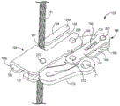
fig. 1 is a first side perspective view of a rope glider according to an embodiment of the present invention;
fig. 2 is an unassembled first side perspective view of the rope glider of fig. 1;
FIG. 3A is a first side perspective view of the rope glider of FIG. 1 initially positioned for mounting to a rope;
fig. 3B is a first side perspective view of the rope glide of fig. 1 positioned on the rope in an open configuration;
fig. 3C is a first side perspective view of the rope glide of fig. 1 positioned on the rope in a closed configuration;
figure 4A is a rear view of the rope traveler of figure 1 coupled to a portion of a fall arrest system of one embodiment of the invention;
fig. 4B is a first side view of a portion of the cable runner and fall protection system of fig. 4A;
fig. 5 is a second side view of the rope glide of fig. 1 in an open configuration;
fig. 6 is a first side view of the rope glider of fig. 1 in an open configuration;
FIG. 7 is a first side perspective view of the rope glide of FIG. 1 showing one embodiment of an anti-backup pawl;
FIG. 8 is a first side perspective view of the rope glide of FIG. 1 in an inverted orientation, further illustrating the anti-backup pawl;
fig. 9A is a rear view of the rope glide of fig. 1 immediately following the rope glide being in an inverted horizontal orientation;
fig. 9B is a rear view of the rope glide of fig. 1 in an inverted horizontal orientation after the anti-backup pawl has been moved;
fig. 10A is a rear view of the rope glide of fig. 1 immediately following the rope glide being in an inverted vertical orientation;
fig. 10B is a rear view of the rope glide of fig. 1 in an inverted vertical orientation after the anti-backup pawl has been moved;
fig. 11 is a first side perspective view of a rope glider according to another embodiment of the present invention;
fig. 12 is a first side perspective view of the rope glider of fig. 11, unassembled;
fig. 13A is a first side perspective view of the rope glider of fig. 11 initially positioned for mounting to a rope;
fig. 13B is a first side perspective view of the rope glide of fig. 11 positioned on the rope in an open configuration;
fig. 13C is a first side perspective view of the rope glide of fig. 11 positioned on the rope in a closed configuration;
fig. 14A is a rear view of the rope glider of fig. 11;
fig. 14B is a first side view of the rope glider of fig. 11 in a closed configuration;
fig. 15 is a second side view of the rope glide of fig. 11 in an open configuration;
fig. 16 is a first side view of the rope glider of fig. 11 in an open configuration;
FIG. 17A is a first side perspective view of the rope glide of FIG. 11 showing one embodiment of an anti-backup pawl;
FIG. 17B is a first side perspective view of the rope runner illustrating an anti-backup pawl configuration of another embodiment of the present invention;
fig. 18A is a first side perspective view of the rope glide of fig. 11 showing the anti-backup pawl in an inverted orientation;
FIG. 18B is a first side perspective view of the rope glide of FIG. 17B showing the anti-backup pawl in an inverted orientation;
fig. 19A is a rear view of the rope glide of fig. 11 immediately following the rope glide being in an inverted horizontal orientation;
fig. 19B is a rear view of the rope glide of fig. 11 in an inverted horizontal orientation after the anti-backup pawl has been moved;
fig. 20A is a rear view of the rope glide of fig. 11 immediately following the rope glide being in an inverted vertical orientation;
fig. 20B is a rear view of the rope glide of fig. 11 in an inverted vertical orientation after the anti-backup pawl has been moved;
fig. 21 is a partial side view of the cable runner of fig. 11 illustrating operation of the plunger of one embodiment.
In accordance with common practice, the various described features are not drawn to scale but are drawn to emphasize specific features relevant to the present invention. Reference numerals indicate similar elements throughout the drawings and text.
DETAILED DESCRIPTION OF EMBODIMENT (S) OF INVENTION
In the following detailed description, reference is made to the accompanying drawings, which form a part hereof, and in which is shown by way of illustration embodiments in which the invention may be practiced. These embodiments are described in detail to enable those skilled in the art to practice the invention, and it is to be understood that other embodiments may be utilized and that mechanical changes may be made without departing from the spirit and scope of the present invention. The following detailed description is, therefore, not to be taken in a limiting sense, and the scope of the present invention is defined only by the appended claims and equivalents thereof.
Embodiments of the present invention provide a rope slider configured to prevent operation of the rope slider when the slider is incorrectly positioned relative to the rope to which the rope slider is to be attached. Embodiments employ a master assembly having a dynamic parallelogram geometry that allows an open configuration when opposing parallel members are closest to each other and a closed configuration when opposing parallel members are furthest from each other, as discussed further below. In some embodiments, when the rope glider is improperly inverted, as discussed in detail below, the parallelogram geometry is limited by an anti-inversion pawl (anti-inversion paw) to prevent the rope glider from being erroneously mounted on the rope. Further, in one embodiment, when the rope slider (or the main assembly of the rope slider) is in the open configuration, the attachment eye is at least partially blocked to prevent attachment of the safety protection system to the rope slider until the rope slider is properly mounted on the rope. This will be described in detail below. Although the above embodiments are shown and described as features of a rope slider, one or both of these features may be used to indicate that a rope slider is or has been improperly installed. In other words, the rope runner may include only the anti-reverse pawl that blocks the movement of the main assembly or blocks the attachment eye. Further, the rope glider may include these features as well as others described in detail below.
Referring to fig. 1, a rope traveler 100 is shown in one embodiment. The rope glider 100 is shown in an open position in fig. 1. An example of a rope skid 100 in a closed position is shown in fig. 7. Fig. 2 shows an unassembled view of the rope sled 100. The rope glider 100 is described herein with reference to fig. 1 and 2. The rope runner 100 includes a first body plate 102 and a second body plate 104 that constitute a housing 195 of the rope runner 100. The first body plate 102 and the second body plate 104 are each generally L-shaped. The first body plate 102 includes a first body portion 102a and a second body portion 102 b. The first body plate 102 is further depicted as having a first plate edge 102c and an opposing second plate edge 102 d. The second body plate 104 also includes first and second body portions 104a, 104b and first and second plate edges 104c, 104 d. The first body portion 102a of the first body plate 102 includes an upper attachment hole 107 and a cord hole 109. The cord aperture 109 is located proximate the first edge 102c of the first body panel 102. The second body portion 102b of the first body plate 102 includes a C-shaped lower guide 102e extending from the second plate edge 102d to form a lower cord guide channel 103. The second body portion 102b of the first body plate 102 further includes a lower connection hole 111. The first body portion 104a of the second body plate 104 includes a C-shaped upper guide 104e extending from the second plate edge 104d to form an upper cord guide channel 105. The second body plate 104 includes an upper connection hole 115 in the first body portion 104a of the second body plate 104 and a lower connection hole 117 in the second body portion 104b of the second body plate 104.
In one embodiment, tether 114 is connected to first body panel 102. In particular, a first end of the cord is guided through a cord hole 109 in the first body plate 102. The first end of the cord is folded back on itself and secured to itself by a first ferrule 116. In one embodiment, the second end of the cord is folded back on itself and secured to itself by a second ferrule 118 to form a cord loop 119. The rope glider 100 in this embodiment includes a first tab 120 and a second tab 124. The first label 120 includes a first label aperture 121 and a spaced apart second label aperture 123. The first label 120 is adhered to the first body plate 102 such that the first label hole 121 is aligned with the upper attachment hole 107 and the second label hole 123 is aligned with the lower attachment hole 111 of the first body plate 102. The second label 124 includes a first label aperture 125 and a spaced apart second label aperture 126. The second label 124 is adhered to the second body panel 104 such that the first label hole 125 is aligned with the upper attachment hole 115 and the second label hole 126 is aligned with the lower attachment hole 117 of the second body panel 104.
The rope sled 100 also includes a first arm link 130 and a second arm link 140. First arm link 130 includes a first end 130a and an opposite second end 130 b. The first end 130a is spaced apart from the second end 130b via an elongated intermediate portion 130 c. The first end 130a of the first arm link 130 includes a first arm hole 131, and the second end 130b of the first arm link 130 includes a second arm hole 133. The intermediate portion 130c of the first arm link 130 includes a first arm receiving slot 135. Located between the first arm receiving slot 135 and the first arm aperture 131 is an offset end retaining aperture 137. In one embodiment, both first end 130a and second end 130b of first arm link 130 terminate in a rounded edge.
The rope sled 100 further comprises a first cam arm 150 and a second cam arm 160. The first cam arm 150 includes a first end 150a that terminates in a rounded edge and an opposite second end 150b that also terminates in a rounded edge. Between the first end 150a and the second end 150b is an elongated middle portion 150 c. The first cam arm 150 also includes a first edge 150d and an opposing second edge 150 e. First and second edges 150d and 150e extend between first and second ends 150a and 150 b. The first edge 150d of the first cam arm 150 includes a cutout portion 156 proximate the intermediate portion 150 c. The first cam arm 150 also has a stop tab 158 extending from the first edge 150d near the second end 150 b. The first cam arm 150 includes a first bore 151 in the first end portion 150a, a second bore 153 in the middle portion 150c proximate the first end portion 150a, a third bore 157 in the middle portion 150c proximate the second end portion 150b, and a fourth bore 159 in the second end portion 150 b.
The second cam arm 160 includes a first end 160a that terminates in a rounded edge and an opposite second end 160b that also terminates in a rounded edge. Between the first end 160a and the second end 160b is an elongated middle portion 160 c. The second cam arm 160 includes a first bore (not shown) in the first end portion 160a, a second bore 161 in the middle portion 160c adjacent the first end portion 160a, a third bore 163 in the middle portion 160c adjacent the second end portion 160b, a fourth bore 165 in the second end portion 160b, and an offset end retaining bore 167 positioned adjacent the third bore 163. The first aperture in the second cam arm 160 is aligned with the first aperture 151 of the first cam arm 150.
The rope traveler 100 also includes a control arm 170. In one embodiment, the control arm 170 is made of an energy absorbing deformable elongated member. The control arm 170 includes a first end 172a having an attachment eye 171 and a second end 172b having a first aperture 174. The control arm 170 further includes a first arm portion 170a, a second arm portion 170b, and a third arm portion 170c that are initially folded over each other. During a fall event, the first arm 170a, second arm 170b, and third arm 170c straighten relative to one another to absorb energy. In one embodiment, the first face 173 of the first end 172a of the first arm 170a engages the second face 175 of the second arm 170 b. A selected amount of force is required to move the first face 173 of the first arm 170a out of contact with the second face 175 of the second arm 170 b. The control arm 170 further includes a second aperture 176 proximate the second arm portion 170b and the third arm portion 170 c.
The rope runner 100 also includes an anti-backup pawl 180. The anti-backup pawl 180 includes a base 180a and a detent 180b extending from the base 180a, and in one embodiment, the base 180a is substantially triangular in shape. The catch 180b includes a first stop wall 182 and a spaced apart second stop wall 183 defining a catch area 181 therebetween. Also included in the rope runner 100 is a biasing member 190 having a first end 190a, a second end 190b, and a coiled portion 190 c.
Here, the connection of the components of the rope runner 100 is provided. The first rivet pin 202 is received in the first hole 151 of the first cam arm 150 and the first hole (not shown) of the second cam arm 160, the second rivet pin 204 is received in the third hole 157 of the first cam arm 150 and the third hole 163 of the second cam arm 160, and the first rivet pin 202 and the second rivet pin 204 couple the first cam arm 150 to the second cam arm 160. A first rivet 206 having a central portion 206a of a first diameter is received within the second bore 153 of the first cam arm 150 and the second bore 161 of the second cam arm 160. The first end 206b of the first rivet 206 having the second smaller diameter is received in the upper attachment hole 107 of the first body plate 102 and the first label hole 121 of the first label 120. The first washer 220 is positioned about the first end 206b of the first rivet 206 between the first body plate 102 and the first cam arm 150. The second end 206c of the first rivet 206 having the second smaller diameter is received in the upper coupling hole 115 of the second body plate 104 and the second label hole 125 of the second label 124. A second washer 222 is positioned about the second end 206c of the first rivet 206 between the second body plate 104 and the second cam arm 160.
A second rivet 208 having a central portion 208a of a first diameter is received within the fourth aperture 159 of the first cam arm 150 and the fourth aperture 165 of the second cam arm 160. The first end 208b of the second rivet 208 having the second smaller diameter is received in the first arm hole 131 of the first arm link 130, and the second end 208c of the second rivet 208 having the second smaller diameter is received in the first arm hole of the second arm link 140. The coiled portion 190c of the biasing member 190 surrounds the central portion 208a of the second rivet 208 and is received within the fourth aperture 159 of the first cam arm 150. Further, the first end 190a of the biasing member 190 is received within the biasing end retaining aperture 137 of the first arm link 130 while the second end 190b of the biasing member 190 is received within the biasing end retaining aperture 167 of the second cam arm 160. The positioning of the biasing member 190 is further illustrated in fig. 7. In one embodiment, the biasing member is positioned to exert a biasing force on the first and second cam arms 150 and 160 to engage the cable 300.
Referring back to fig. 2, a central portion 210a of the third rivet 210 having the first diameter is received within the first aperture 174 of the control arm 170. The first end 210b of the third rivet 210 having the second smaller diameter is received in the lower coupling hole 111 of the first body plate 102 and the second tag hole 123 of the first tag 121. A third washer 224 is positioned about the first end 210b of the first rivet 210 between the first body plate 102 and the control arm 170. The second end 210c of the third rivet 210 having the second smaller diameter is received in the lower coupling hole 117 of the second body plate 104 and the second tag hole 126 of the second tag 124. A fourth washer 226 is positioned about the second end 210c of the third rivet 210 between the second body plate 104 and the control arm 170.
A fourth rivet 212 having a central portion 212a of the first diameter is received within the second bore 176 of the control arm 170. A first end 212b of the fourth rivet 212 having a second diameter smaller than the first diameter is received within the second arm aperture 133 of the first arm link 130. Fifth washer 228 is positioned about first end 212b of fourth rivet 212 between first arm link 130 and control arm 170. The second end 212c of the fourth rivet 212 having the second smaller diameter is received in the second arm hole 143 of the second arm link 140. A sixth washer 230 is positioned about the second end 212c of the fourth rivet 212 between the second arm link 140 and the control arm 170. The anti-backup pawl 180 is slidably retained within the first arm receiving slot 135 of the first arm link 130 and the second arm receiving channel 145 of the second arm link 140. In particular, a portion of the base 180a of the anti-backup pawl 180 is slidably received within the first arm receiving slot 135 of the first arm link 130, and the detent 180b of the anti-backup pawl 180 is slidably received within the second arm receiving channel 145 of the second arm link 140. In one embodiment, at least one of the stop walls 182 and 183 retains the detent 180b of the anti-backup pawl 180 in the second arm receiving channel 145 of the second arm link 140.
The rope runner 100 is designed with a main assembly 196, the main assembly 196 having a dynamic parallelogram geometry (four parts and four pivot points). The four components that constitute the main assembly 196 include first and second arm links 130 and 140 and first and second cam arms 150 and 160. Four pivot points are created by rivets 206, 208, 210 and 212. The cable runner 100 is in an open configuration when the opposing parallel members (first and second arm links 130 and 140 and first and second cam arms 150 and 160) are closest to each other and the cable runner 100 is in a closed configuration when the opposing parallel members (first and second arm links 130 and 140 and first and second cam arms 150 and 160) are furthest from each other. An example of engaging the rope sled 100 to the rope 300 in the correct orientation is shown in fig. 3A-3C. In fig. 3A, the rope runner 100 is in a closed open configuration. As shown, the rope runner 100 is inclined so that the rope 300 can be accommodated in the rope entry passage 101 between the upper guide 104e of the second body plate 104 and the lower guide 102e of the first body plate 102. In this example, the inlet of the upper rope guide passage 105 formed by the upper guide 104e faces upward. In this position, the rope runner 100 can be properly mounted on the rope 300. Fig. 3B shows the rope runner 100 rotated such that the rope 300 is received in the lower rope guide channel 103 of the first body plate 102 and the upper rope guide channel 105 of the second body plate 104. In fig. 3B, the rope runner 100 is still in the open configuration. Fig. 3C shows actuation of the cable runner 100 to engage the cable 300. Further, fig. 3C shows the rope sled 100 in a closed configuration. In this configuration, the first end 150a of the first cam arm 150 and the first end 160a of the second cam arm 160 engage the cable 300 in the upper guide 104e of the housing 195, while the second end 172b of the control arm 170 also engages the cable 300 in the lower guide 102e of the housing 192. The fall protection system can then be attached to the attachment eye 171 of the control arm 170. In the event of a fall event, the force on the control arm 170 will force the first ends 150a, 160a of the first and second cam arms 150, 160 and the second end 172b of the control arm 170 into the cord 300 to arrest the fall.
Referring to fig. 4A and 4B, a diagram of a portion of a fall protection system attached to an attachment eye 171 of a control arm 170 is shown. This portion of the fall arrest system includes a first safety hook 320 coupled to control arm 170, a linkage 324, and a second safety hook 322 coupled to linkage 324. The second safety hook 322 will in turn be coupled to a safety harness (not shown) worn by the user via a D-ring, lanyard, lifeline, or the like. As shown in fig. 4B, cord 114 is coupled between first body plate 102 and first snap hook 320.
The design of the embodiment of the rope skid 100 includes features that prevent its use until it is properly attached to the rope 300. In one embodiment, the rope sled 100 is designed to lock the geometry of the main assembly 196 in a closed configuration when the rope sled 100 is inverted (incorrectly oriented). Further, the anti-backup pawl 180 may prevent the rope sled from reclosing (i.e., in a closed configuration) if the user opens the rope sled before reversing the rope sled. Furthermore, the attachment eye 171 is blocked and thus the fall arrest system cannot be coupled to a rope runner. For example, referring to the second side view of the assembled cable runner 100 in fig. 5, it is shown that the extended raised portion 146 of the second arm link 140 at least partially obstructs the attachment eye 171 of the control arm 170 when the cable runner 100 (or main assembly 196) is in the open configuration. This prevents attachment of the fall protection system to the rope runner 100 until the rope runner 100 is properly attached to the rope 300 and in a closed configuration. The first side view in fig. 6 also shows that the lug blocking portion 146 of the second arm link 140 at least partially blocks the attachment eye 171 of the control arm 170 when the rope glide is in the open configuration.
The opening and closing of the rope runner 100 is selectively limited by an anti-backup pawl 180 that selectively engages a stop projection 158 on the first cam arm 150. When the rope runner 100 is in the correct orientation for mounting on the rope 300, the pawl 180 is weighted to avoid the stop projection 158 and the rope runner 100 can be opened and closed. For example, referring to fig. 7, a rope sled 100 is provided, shown in an upright position. In this view, the first arm link 130 is drawn in phantom to illustrate the position of the floating anti-backup pawl 180 when the cable link is in this orientation. As shown, the anti-backup pawl 180 in this orientation is weighted to point toward the second arm link 140 to clear the stop boss 158 on the first cam arm 150. Thus, the rope runner 100 in this configuration is free to be opened (i.e., the rope runner 100 can be freely made to assume an open configuration), which would allow the rope 300 to be inserted into the upper and lower rope guide channels 103 and 105 of the rope runner, as described above with respect to fig. 3A-3C. Referring now to fig. 7, a pictorial view of the rope skid 100 is shown inverted. Here again, the first arm link 130 is drawn in phantom to illustrate the position of the anti-backup pawl 180. In this inverted orientation, the shape and weight of the anti-backup pawl 180 positions the anti-backup pawl 180 toward the first arm link 130. In this position, as shown, a portion of the anti-backup pawl 180 engages the stop projection 158 of the first cam arm 150. This prevents the rope runner 100 from being opened (changed to the open orientation). Thus, the cable 100 cannot be positioned within the upper cable guide channel 105, thereby preventing the connector of the cable traveler from beginning to couple to the cable 300 in an inverted orientation.
The anti-backup pawl 180 movement to prevent the rope runner 100 from opening is further illustrated in the rear view of fig. 9A and 9B. In these illustrations, the rope sled 100 has been positioned horizontally in an inverted orientation. Fig. 9A shows the position of the anti-backup pawl 180 when the rope runner is initially in the inverted horizontal position. FIG. 9B illustrates how the shape and weight of the anti-backup pawl 180 positions the anti-backup pawl 180 to slide within the first arm receiving slot 135 of the first arm 130 and the second arm receiving channel 145 of the second arm link 140 to prevent movement of the stop projection 158 of the first cam arm 150. In this configuration, the kinematic parallelogram geometry of the main assembly 196 (four components and four pivot points) comprised of the first and second arm links 130 and 140 and the first and second cam arms 150 and 160 cannot pivot along the four pivot points created by the rivets 206, 208, 210 and 212 to position the rope glide 100 in the open configuration.
A rear view of the inverted vertically oriented rope sled 100 is shown in fig. 10A and 10B. In particular, fig. 10A and 10B illustrate the movement of the anti-backup pawl 180 when the rope runner 100 is vertically inverted. Fig. 10A shows the position of the anti-backup pawl 180 when the rope runner 100 is initially in the reverse vertical position. FIG. 10B illustrates how the weight and shape of the anti-backup pawl 180 causes the anti-backup pawl 180 to slide within the first arm receiving slot 135 of the first arm 130 and the second arm receiving channel 145 of the second arm link 140 to be positioned in engagement with the stop projection 158 of the first cam arm 150. In this configuration, the kinematic parallelogram geometry of the main assembly 196 (four components and four pivot points) comprised of the first and second arm links 130 and 140 and the first and second cam arms 150 and 160 cannot pivot along the four pivot points created by the rivets 206, 208, 210 and 212 to position the cable runner in the open orientation. Thus, in an incorrect inverted horizontal or vertical orientation, the anti-backup pawl 180 descends and rotates in the path of the stop projection 158 of the first cam arm 150, preventing the rope runner 100 from opening, thus preventing the rope runner 100 from being mounted on the rope 300.
Furthermore, by design of the cable runner 100, if the cable runner 100 is opened in the correct orientation and then rotated 180 degrees to an inverted orientation, although the cable will be able to be received within the lower and upper cable guide channels 103 and 105, the positioning of the anti-backup pawl 180 will engage the other side of the stop projection 158, preventing the cable runner 100 from closing to the closed configuration. This will make it apparent to the user that the rope runner 100 is not properly attached to the rope 300.
Referring to fig. 11, another embodiment of a rope skid 400 is shown. The cable traveler 400 in fig. 11 is shown in the closed position. An example of a rope sled 400 in an open position is shown in fig. 17. Fig. 12 shows an unassembled view of the rope glide 400. The rope glide 400 is described herein with reference to fig. 11 and 12. The rope slider 400 includes a first body plate 402 and a second body plate 404 that constitute a housing 495 of the rope slider 400. In this embodiment, both the first body plate 402 and the second body plate 404 are substantially L-shaped. The first body plate 402 includes a first body portion 402a and a second body portion 402 b. The first body plate 402 is further depicted as having a first plate edge 402c and an opposing second plate edge 402 d. The second body plate 404 further comprises a first body portion 404a and a second body portion 404b and a first plate edge 404c and an opposite second plate edge 404 d. The first body portion 402a of the first body plate 402 includes an upper connection hole 407. The second body portion 402b of the first body plate 402 includes a C-shaped lower guide 402e extending from the second plate edge 402d to form a lower cord guide channel 403. The second body portion 402b of the first body plate 402 also includes a lower connection hole 411. The first body portion 404a of the second body plate 404 includes a C-shaped upper guide 404e extending from the second plate edge 404d to form an upper cord guide channel 405. Second body plate 404 includes upper connection holes 415 in first body portion 404a of second body plate 404 and lower connection holes 417 in second body portion 404b of second body plate 404.
The rope glider 400 in this embodiment includes a first tab 420 and a second tab 424. The first label 420 includes first label holes 421 and spaced apart second label holes 423. The first label 420 is adhered to the first body plate 402 such that the first label hole 421 is aligned with the upper connection hole 407 and the second label hole 423 is aligned with the lower connection hole 411 of the first body plate 402. The second label 424 includes a first label aperture 425 and a spaced apart second label aperture 426. The second label 424 is adhered to the second body panel 404 such that the first label hole 425 is aligned with the upper attachment hole 415 and the second label hole 426 is aligned with the lower attachment hole 417 of the second body panel 404.
The rope sled 400 further comprises a first arm link 430 and a second arm link 440. First arm link 430 includes a first end 430a and an opposite second end 430 b. The first end 430a is spaced apart from the second end 430b via an elongated middle portion 430 c. The first end 430a of the first arm link 430 includes a first arm hole 431, and the second end 430b of the first arm link 430 includes a second arm hole 433. The intermediate portion 430c of the first arm link 430 includes a first arm receiving slot 435. Located between the first arm receiving slot 435 and the first arm aperture 431 is an offset end retaining aperture 437. In one embodiment, both first end 430a and second end 430b of first arm link 430 terminate in a rounded edge.
The rope sled 400 further comprises a first cam arm 450 and a second cam arm 460. The first cam arm 450 includes a first end 450a that terminates in a rounded edge and an opposite second end 450b that also terminates in a rounded edge. Between the first end 450a and the second end 450b is an elongated middle portion 450 c. The first cam arm 450 also includes a first edge 450d and an opposing second edge 450 e. First edge 450d and second edge 450e extend between first end 450a and second end 450 b. The first edge 450d of the first cam arm 450 includes a cutout portion 456 adjacent the intermediate portion 450 c. The first cam arm 450 also has a stop projection 458 extending from the first edge 450d near the second end 450 b. The first cam arm 450 includes a first aperture 451 in the first end 450a, a second aperture 453 in the midsection 450c proximate the first end 450a, a third aperture 457 in the midsection 450c proximate the second end 450b, and a fourth aperture 459 in the second end 450 b.
The second cam arm 460 includes a first end 460a that terminates in a rounded edge and an opposite second end 460b that also terminates in a rounded edge. Between the first end 460a and the second end 460b is an elongated intermediate portion 460 c. The second cam arm 460 includes a first bore 462 in the first end portion 460a, a second bore 461 in the intermediate portion 460c adjacent the first end portion 460a, a third bore 463 in the intermediate portion 460c adjacent the second end portion 460b, a fourth bore 465 in the second end portion 460b, and an offset end retaining bore 467 located adjacent the third bore 463. The first aperture in the second cam arm 460 is aligned with the first aperture 451 of the first cam arm 450.
The rope sled 400 also includes a control arm 470. In this embodiment, the control arm 470 is made of an energy absorbing deformable elongated member. The control arm 470 includes a first end 472a having an attachment eye 471 and a second end 472b having a first aperture 474. The control arm 470 further includes a first arm portion 470a, a second arm portion 470b, and a third arm portion 470c that are initially folded over each other. During a fall event, the first arm 470a, second arm 470b, and third arm 470c straighten out with respect to one another to absorb energy. In the present embodiment, the first face 473a of the first end 472a of the first arm 470a engages the second face 473b of the second arm 470 b. A selected amount of force is required to disengage the first face 473a of the first arm 470a from the second face 473b of the second arm 470 b. Further, in the present embodiment, the first face 475a of the second arm 470b engages the second face 475b of the third arm 470 c. A selected amount of force is required to disengage the first face 475a of the second arm 470b from the second face 475b of the third arm 470 c. The control arm 470 further includes a second aperture 476 proximate the second arm portion 470b and the third arm portion 470 c.
The rope glide 400 also includes an anti-backup pawl 480. Anti-backup pawl 480 includes a base 480a and a catch 480b extending from base 480a, in one embodiment, base 480a is substantially triangular in shape. The retaining section 480b includes a first stop wall 482 and a spaced apart second stop wall 483 defining a retaining area 481 therebetween. Also included in the rope glide 400 is a biasing member 490 having a first end 490a, a second end 490b, and a coiled portion 490 c. A plunger assembly 600 is also included in this embodiment. The plunger assembly 600 provides an additional safety feature for the cable traveler 400. The plunger assembly 600 is designed to prevent the cable runner 400 from being positioned in the open configuration without manipulation of the plunger assembly 600, as discussed in further detail below. The plunger assembly 600 includes a plunger 606 having a tubular main portion 606a and an extension arm stop 606 b. An extension arm stop 606b extends from one end of the main portion 606 a. The extension arm stop 606b is received in a stop slot channel 611 extending through the first body portion 402a of the first body plate 402. The plunger assembly 600 also includes a mounting rod 602. The mounting bar 602 includes a head end 602a, an intermediate portion 602b, and a second end 602 c. The second end 602c is received within the plunger bore 613 in the first body portion 402a of the first body plate 402 proximate the stop slot channel 611. A retaining cap 602d coupled to a terminal end of the second end 602c of the mounting stem 602 couples the mounting stem 602 to the first body plate 402. The main portion 606a of the plunger 606 also includes an offset cavity 607 that leads to a smaller rod passage (not shown). At least the middle portion 602b of the mounting stem 602 is received in the offset cavity 607 of the plunger 606, with the mounting stem 602 passing through the smaller stem passage. The biasing member 604 surrounds the intermediate portion 602b of the mounting stem 602 and is received within the biasing cavity 607 of the plunger 606. The biasing member 604 has a first end that engages the head end 602a of the mounting rod 602. The biasing member 604 has a second end that engages an inner surface (not shown) within the biasing cavity 607 of the plunger 606. The biasing member 604 positioned in this manner exerts a biasing force on the plunger 606 to force the extension arm stop 606b into the stop slot channel 611 through the first body plate 402. The extension arm stop 606b limits the movement of the first cam arm 450 when extending through the stop slot channel 611 of the first body plate 402. This provides a security feature as described in detail below.
Here, the connection of the components of the rope glide 400 is provided. First rivet pin 502 is received within first aperture 451 of first cam arm 450 and first aperture 462 of second cam arm 460, and second rivet pin 504 is received within third aperture 457 of first cam arm 450 and third aperture 463 of second cam arm 460 to operatively couple first cam arm 450 to second cam arm 460. The first rivet 506 having the central portion 506a of the first diameter is received within the second aperture 453 of the first cam arm 450 and the second aperture 461 of the second cam arm 460. The first end 506b of the first rivet 506 having the second smaller diameter is received in the upper coupling hole 407 of the first body plate 402 and the first label hole 421 of the first label 420. The first washer 521 is positioned around the first end 506b of the first rivet 506 between the first body plate 402 and the first cam arm 450. The second end 506c of the first rivet 506 having the second smaller diameter is received within the upper attachment aperture 415 of the second body plate 404 and the second label aperture 425 of the second label 424. A second washer 522 is positioned around the second end 506c of the first rivet 506 between the second body plate 404 and the second cam arm 460.
A second rivet 510 having a central portion 510a of a first diameter is received within the fourth aperture 459 of the first cam arm 450 and the fourth aperture 465 of the second cam arm 460. A first end 510b of a second rivet 510 having a second smaller diameter is received in a first arm hole 431 of the first arm link 430, and a second end 510c of the second rivet 510 having the second smaller diameter is received in a first arm hole 441 of the second arm link 440. The coiled portion 490c of the biasing member 490 is received around the central portion 510a of the second rivet 510 and within the fourth aperture 459 of the first cam arm 450. In addition, the first end 490a of the biasing member 490 is received within the biasing end retaining aperture 437 of the first arm link 430, while the second end 490b of the biasing member 490 is received within the biasing end retaining aperture 467 of the second cam arm 460. The positioning of the biasing member 490 is further illustrated in fig. 17. In one embodiment, the biasing member is positioned to exert a biasing force on the first and second cam arms 450 and 460 to engage the cable 650.
Referring back to fig. 12, the central portion 508a of the third rivet 508 having the first diameter is received within the first bore 474 of the control arm 470. The first end 508b of the third rivet 508 having the second smaller diameter is received in the lower coupling hole 411 of the first body plate 402 and the second label hole 423 of the first label 421. Third, fourth, and fifth shims 524a, 524b, and 524c are positioned between first main plate 402 and control arm 470 about first end 508b of third rivet 508. The second end 508c of the third rivet 508 having the second smaller diameter is received within the lower attachment hole 417 of the second body plate 404 and the second label hole 426 of the second label 424. Sixth, seventh and eighth shims 526a, 526b and 526c are positioned between second body plate 404 and control arm 470 about second end 508c of third rivet 508.
A fourth rivet 512 having a central portion 512a of the first diameter is received within the second bore 476 of the control arm 470. The first end 512b of the second rivet 512, which has a second smaller diameter that is smaller than the first diameter, is received within the second arm hole 433 of the first arm link 430. Ninth and tenth shims 528a and 528b are positioned between first arm link 430 and control arm 470 about first end 512b of fourth rivet 512. Second end 512c of fourth rivet 512 having a second smaller diameter is received within second arm aperture 443 of second arm link 440. Eleventh and twelfth spacers 530a and 530b are positioned around the second end 512c of the fourth rivet 512 between the second arm link 440 and the control arm 470. The anti-backup pawl 480 is slidably retained within the first arm receiving slot 435 of the first arm link 430 and the second arm receiving channel 445 of the second arm link 440. Specifically, a portion of the base 480a of the anti-backup pawl 480 is slidably received within the first arm receiving slot 435 of the first arm link 430, and the catch 480b of the anti-backup pawl 480 is slidably received within the second arm receiving channel 445 of the second arm link 440. In one embodiment, at least one of the stop walls 482 and 483 retains the detent 480b of the anti-backup pawl 480 in the second arm receiving passage 445 of the second arm link 440.
The rope glide 400 is designed with a main assembly 496, the main assembly 496 having a dynamic parallelogram geometry (four components and four pivot points). The four components that make up the main assembly 496 include first and second arm links 430 and 440 and first and second cam arms 450 and 460. The four pivot points are created by rivets 506, 508, 510 and 512. The cable runner 400 is in a closed configuration when the opposing parallel members (first and second arm links 430 and 440 and first and second cam arms 450 and 460) are closest to each other and the cable runner 400 is in an open configuration when the opposing parallel members (first and second arm links 430 and 440 and first and second cam arms 450 and 460) are furthest from each other.
An example of engaging the rope sled 400 to the rope 650 in the correct orientation is shown in fig. 13A-13C. In fig. 13A, the rope glide 400 is in an open configuration. This open configuration is used when the rope glider 400 is mounted on the rope 650. In this configuration, the first ends 450a and 460a of the respective first and second cam arms 450 and 460 move away from the entrant region to the lower cable guide channel 403 and the upper cable guide channel 405 formed by the first and second body plates 402 and 404. As shown in fig. 13A, the rope runner 400 is inclined so that the rope 650 can be received in the rope entry channel 401, the rope entry channel 401 being located between the upper guide 404e of the second body plate 404 and the lower guide 402e of the first body plate 402. In this example, the entrance of the upper rope guide passage 405 formed by the upper guide 404e faces upward. In this position, the rope sled 400 can be properly mounted on the rope 650. Further, in the open configuration, the plunger 606 is pulled outward relative to the first body plate 402 to counteract the biasing force of the biasing member 604, eliminating the engagement of the extension arm stop 606b of the plunger 606 with the edge of the first cam arm 450.
Fig. 13B shows the rope runner 400 rotated such that the rope 650 is received in the lower rope guide channel 403 of the first body plate 402 and the upper rope guide channel 405 of the second body plate 404. In fig. 13B, the cable runner 400 is still in the open configuration with the plunger 606 in a pulled out position relative to the first body plate 402. This is due to the engagement of the extension arm stop 606b of the plunger 606 with the surface of the intermediate portion of the first cam arm 450. Fig. 13C shows the actuation of the cable runner 400 to engage the cable 650. Further, fig. 3C shows the rope glide 400 in a closed configuration. In this configuration, the first end 450a of the first cam arm 450 and the first end 460a of the second cam arm 460 engage the cable 650 in the upper guide 404e of the housing 495. Further, in this configuration, the second end 472b of the control arm 470 engages the cable 650 in the lower guide 402e of the housing 495. The fall protection system can then be attached to the snap hook 520 attached to the attachment eye 471 of the control arm 470. In the event of a fall event, the force on the control arm 470 will force the first end 450a of the first cam arm 450 and the first end 460a of the second cam arm 460 and the second end 472b of the control arm 470 into the cord 650 to arrest the fall. As shown in fig. 13C, the plunger 606 is no longer in the withdrawn position. With the first cam arm 450 having moved, the biasing member 604 is now free to force the extension arm stop 606b through the stop slot channel 611 of the first body plate 402. In this position, the extension arm stop 606b limits the movement of the first cam arm 450 so the rope sled 400 cannot be positioned in the open configuration, thereby preventing accidental disengagement of the rope sled 400 from the rope 650.
Fig. 14A and 14B further illustrate different views of the rope glide 400 and the snap hook 520. Specifically, fig. 14A is a rear view of the rope sled 400 and fig. 14B is a first side view of the rope sled 400 in a closed configuration. As described above, the hook 520 will be coupled to a fall arrest system connected to the user. Fig. 15 shows a second side view of the rope sled 400 in an open configuration. Additionally fig. 16 shows a first side view of the rope glide 400 in an open configuration.
The design of the embodiment of the rope skid 400 includes features that prevent its use until it is properly attached to the rope 650. In one embodiment, the cable glider 400 is designed to lock the geometry of the main assembly 496 in a closed configuration when the glider 400 is inverted (incorrectly oriented). Further, if the user places the rope sled 400 in an open configuration, the anti-backup pawl 480 prevents the rope sled 400 from re-closing (i.e., in a closed configuration) before it is reversed. Further, in the present embodiment as described above, if the plunger 606 of the plunger assembly 600 is not pulled relative to the first body plate 402, the extension arm stop 606b limits the movement of the first cam arm 450 such that the cable runner 400 cannot be changed from the closed configuration to the open configuration for additional safety features.
In this embodiment, the opening and closing of the cable runner 400 is selectively restricted by the anti-backup pawl 480 and the plunger 606 of the plunger assembly 600. The anti-backup pawl 480 selectively engages the stop protrusion 458 on the first cam arm 450. When the cable runner 400 is in the correct orientation for mounting on the cable 650, the anti-backup pawl 480 is weighted to avoid the stop projection 458 and the cable runner 400 can be opened and closed if the plunger 606 is pulled back. For example, referring to fig. 17A, a rope sled 400 is provided, shown in an upright position. In this view, the first arm link 430 is drawn in phantom to illustrate the position of the floating anti-backup pawl 480 when the cable link is in this orientation. As shown, the anti-backup pawl 480 in this orientation is weighted to position toward the second arm link 440 therein to create clearance with the stop projection 458 on the first cam arm 450. Thus, the cable runner 400 in this orientation is free to open (assuming the plunger 606 has been pulled back), which will allow the cable 650 to be inserted into the upper and lower cable guide channels 405 and 403 of the cable runner 400, as discussed above with respect to fig. 13A-13C. Referring now to fig. 18A, a diagram of a rope skid 400 that is inverted is shown. Here again, first arm link 430 is drawn in phantom to illustrate the position of anti-backup pawl 480. In this reverse orientation, the weight of the anti-backup pawl 480 positions the anti-backup pawl 480 toward the first arm link 430. In this position, as shown, a portion of the anti-backup pawl 480 is engaged with the stop projection 458 of the first cam arm 450. This prevents the rope runner 400 from opening (changing to the open orientation). Thus, the cable 650 cannot be positioned within the upper cable guide channel 405, thereby preventing the cable traveler 400 from being coupled to the cable 650 in an inverted orientation. The stop projection 458 also prevents the cable runner 400, which is already in the inverted open configuration, from being moved to the still inverted closed configuration.
Fig. 17B and 18B illustrate another embodiment of a rope runner 700 having a different anti-backup pawl configuration. This embodiment does not implement the stop projection 458 that selectively engages the anti-backup pawl 480 as described above. Referring to fig. 17B, in this embodiment, the second end 450B of the first cam arm 450 includes a stop flange surface 702. The stop flange surface 702 is formed by having a first radial portion 704a of the second end 450b of the first cam 450 have a first diameter and a second radial portion 704b of the second end 450b of the first cam 450 have a second, larger diameter. Stop flange surface 702 is located at the junction between first radial portion 704a and second radial portion 704 b. Fig. 18B shows the rope glider 700 in a closed configuration, while inverted. In this orientation, the pawl 440 engages the stop flange surface 702 to prevent the cable carriage 700, which is already in the closed configuration, from moving to the open configuration. Thus, in this orientation, the rope glider 700 cannot be mounted on the rope. However, in this embodiment (unlike the cable runner 400 having the stop protrusion 458 described above with respect to fig. 17A and 18A), the stop flange surface design allows the cable runner 700 to move to the closed configuration if inverted in the open configuration. Thus, in either embodiment, a stop member (stop protrusion 458 or stop flange surface 702) is used to prevent selective configuration movement of the rope travelers 400 and 700.
The movement of the anti-backup pawl 480 to prevent the rope sled 400 from opening is further illustrated in the rear view of fig. 19A and 19B. In these illustrations, the rope sled 400 has been positioned horizontally in an inverted orientation. Fig. 19A shows the position of the anti-backup pawl 480 when the rope glide is initially in the inverted horizontal position. Fig. 19B illustrates how the weight and shape of the anti-backup pawl 480 causes the anti-backup pawl 480 to slide within the first arm receiving slot 435 of the first arm link 430 and the second arm receiving channel 445 of the second arm link 440 to be positioned to prevent movement by engaging the stop projection 458 of the first cam arm 450. In this configuration, the kinematic parallelogram geometry of the main assembly 496 (four components and four pivot points) made up of the first and second arm links 430 and 440 and the first and second cam arms 450 and 460 cannot pivot along the four pivot points created by the rivets 406, 408, 410 and 412 to position the cable glider in the open orientation.
A rear view of the rope sled 400 in an inverted vertical orientation is shown in fig. 20A and 20B. Specifically, fig. 20A and 20B illustrate the movement of the anti-backup pawl 480 when the rope glide 400 is vertically inverted. Fig. 20A shows the position of the anti-backup pawl 480 when the rope glide is initially in the reverse vertical position. Fig. 20B illustrates how the weight and shape of the anti-backup pawl 480 causes the anti-backup pawl 480 to slide within the first arm receiving slot 435 of the first arm link 430 and the second arm receiving channel 445 of the second arm link 440 to be positioned to prevent movement by engagement of the stop projection 458 of the first cam arm 450. In this configuration, the kinematic parallelogram geometry of the main assembly 496 (four components and four pivot points) made up of the first and second arm links 430 and 440 and the first and second cam arms 450 and 460 cannot pivot along the four pivot points created by the rivets 406, 408, 410 and 412 to position the cable glider in the open orientation. Thus, in an incorrect inverted horizontal or vertical orientation, the anti-backup pawl 480 descends and rotates on the path of the stop projection 458 of the first cam arm 450, preventing the rope runner 400 from opening, thus preventing the rope carriage 400 from being mounted on the rope 650.
As described above, the plunger 606 also prevents the cable runner from moving from the closed configuration to the open configuration. A partial first side view of the cable traveler 400 is shown in fig. 21, showing the plunger 606 engaged with the first edge 450d of the first cam arm 450. The engagement of the plunger 606 with the first edge 450d of the first cam arm 450 prevents the cable runner 400 from moving from the closed configuration to the open configuration. As described above, the plunger 606 must be pulled away from the first body plate 402 to overcome the biasing member 604 to disengage the plunger's extension arm stop 606b from the first cam arm 450. Once the plunger 606 is pulled away from the first body plate 402, the cable runner 400 may be moved into the open configuration, provided the cable runner 400 is in the correct orientation, so the anti-backup pawl 480 does not prevent movement. Fig. 21 further illustrates a third tag 720 secured to the energy absorbing portion of the control arm 470.
The above specification, examples and data provide a complete description of the manufacture and use of the composition of the embodiments of the invention. Although specific embodiments have been illustrated and described herein, it will be appreciated by those of ordinary skill in the art that any arrangement which is calculated to achieve the same purpose may be substituted for the specific embodiments shown. This application is intended to cover any adaptations or variations of the present invention. Therefore, it is manifestly intended that this invention be limited only by the claims and the equivalents thereof.
Claims (18)
1. A rope glider comprising: a housing forming at least one cord guide channel; a main assembly pivotally coupled to the housing, the main assembly being constructed and arranged to have an open configuration permitting a cord to be positioned within the at least one cord guide channel, and a closed configuration engaging the cord in the at least one cord guide channel; an anti-backup pawl constructed and arranged to limit movement of said main assembly when said housing is in a reverse orientation; the main assembly further includes: at least one cam arm pivotally coupled to the housing, the at least one cam arm having a first end configured to engage a cable positioned within the at least one cable guide channel; at least one arm link pivotally coupled to the at least one cam arm, the at least one arm link being constructed and arranged to move relative to the at least one cam arm to form the closed configuration and the open configuration, wherein the anti-backup pawl is constructed and arranged to selectively restrict movement of the at least one cam arm and the at least one arm link relative to each other when the housing is in a reversed orientation.
2. A rope glider according to claim 1, further comprising: the at least one cam arm comprises a first cam arm and a second cam arm, the first cam arm and the second cam arm being in a parallel configuration with respect to each other; and the at least one arm link includes a first arm link and a second arm link spaced apart from each other in a parallel configuration, the first and second cam arms pivotally coupled to the first and second arm links.
3. A rope glider according to claim 2, further comprising: the first arm link has a first arm receiving channel; the second arm link has a second arm receiving channel; and the anti-backup pawl is slidably retained within the first arm receiving channel of the first arm link and the second arm receiving channel of the second arm link.
4. A rope glider according to claim 3, further comprising: the first cam arm has a stop member positioned to engage the anti-backup pawl when the housing is in the inverted orientation.
5. A rope glider according to claim 1, wherein the anti-backup pawl further comprises: a triangular base; and a detent extending from the base, the detent having a first stop wall and a spaced apart second stop wall defining a detent area.
6. A rope glider according to claim 1, further comprising: a control arm pivotally coupled to the housing, the control arm having an attachment eye configured and arranged to couple a fall protection system to the cable traveler; and a portion of the main assembly is positioned to block at least a portion of the attachment eye when the main assembly is in the open configuration.
7. A rope traveller as in claim 6, wherein the main assembly further comprises: at least one cam arm pivotally coupled to the housing, the at least one cam arm having an end selectively configured to engage a cord located within the at least one cord guide channel; at least one arm link having a first end pivotally coupled to said at least one cam arm and a second end pivotally coupled to said control arm, said at least one cam arm, said control arm, and said at least one arm link being constructed and arranged to move relative to one another to form said closed configuration and said open configuration, said at least one arm link further comprising a blocking portion that blocks at least a portion of said attachment eye of said control arm when said main assembly is in said open configuration.
8. A rope traveller as in claim 1, wherein the main assembly further comprises: a control arm pivotally coupled to the housing, the control arm having an attachment eye configured and arranged to couple a fall protection system to the cable traveler, the control arm further comprising an energy absorbing portion.
9. A rope glider according to claim 1, wherein the housing further comprises: a first body plate having a lower guide forming a lower rope guide channel; and a second body plate having an upper guide forming an upper cord guide channel, the lower cord guide channel aligned with the upper cord guide channel, the lower guide spaced from the upper guide to form a cord entry channel, the main assembly pivotally coupled between the first body plate and the second body plate.
10. A rope glider according to claim 1, further comprising: a plunger assembly constructed and arranged to selectively restrict movement of the main assembly.
11. A cable traveler as recited in claim 10, wherein the plunger assembly further comprises: a main portion movably coupled to the housing and an extension arm stop extending from the main portion, the extension arm stop being received in a stop slot channel in the housing; and a plunger biasing member structured and arranged to bias the extension arm stop through the stop slot channel in the housing to selectively engage the main assembly.
12. A rope glider comprising: a housing forming at least one cord guide channel; a control arm pivotally coupled to the housing, the control arm having an attachment eye configured and arranged to couple a fall protection system to the cable traveler; a main assembly pivotally coupled to the housing, the main assembly being constructed and arranged to have an open configuration to allow the cord to be positioned within the at least one cord guide channel, and a closed configuration to engage the cord in the at least one cord guide channel; a plunger assembly constructed and arranged to selectively restrict movement of said main assembly, said plunger assembly comprising: a plunger including a main portion movably coupled to the housing and an extension arm stop extending from the main portion, the extension arm stop being received in a stop slot channel in the housing; and a plunger biasing member structured and arranged to bias the extension arm stop through the stop slot channel in the housing to selectively engage the main assembly; and an anti-backup pawl constructed and arranged to selectively restrict movement of the main assembly when the housing is in a reverse orientation to prevent the rope runner from being mounted on a rope in the reverse orientation.
13. A rope traveller as in claim 12, wherein the main assembly further comprises: at least one cam arm pivotally coupled to the housing, the at least one cam arm having an end selectively configured to engage a cord located in the at least one cord guide channel; at least one arm link having a first end pivotally coupled to the at least one cam arm and a second end pivotally coupled to the control arm, the at least one cam arm, the control arm, and the at least one arm link being constructed and arranged to move relative to one another to form the closed configuration and the open configuration; and the anti-backup pawl is constructed and arranged to selectively restrict movement of the at least one cam arm, the control arm, and the at least one arm link relative to one another when the housing is in a reverse orientation.
14. A rope glider according to claim 13, further comprising: a first arm link having a first arm receiving channel; and a second arm link having a second arm receiving channel;
and the anti-backup pawl is slidably retained within the first arm receiving channel of the first arm link and the second arm receiving channel of the second arm link.
15. A method of forming a rope glider comprising: pivotally coupling a main assembly to a housing, the main assembly being constructed and arranged to move between an open configuration that allows a cable to be positioned within a cable guide channel of the housing, and a closed configuration that engages the cable in the at least one cable guide channel, the main assembly comprising: at least one cam arm pivotally coupled to the housing, the at least one cam arm having a first end configured to engage a cable positioned within the at least one cable guide channel, and at least one arm link pivotally coupled to the at least one cam arm, the at least one arm link being configured and arranged to move relative to the at least one cam arm to form the closed configuration and the open configuration; and engaging a stop member of the main assembly with a ratchet pawl to selectively restrict movement of the at least one cam arm and the at least one arm link relative to each other when the housing is in the reverse orientation.
16. The method of claim 15, further comprising: the movement of the main assembly is limited by an extension arm stop of the plunger assembly.
17. The method of claim 15, further comprising: blocking access to an attachment eye of a control arm attached to the main assembly when the main assembly is in an open configuration.
18. A rope glider comprising:
a housing forming at least one cord guide channel, wherein the housing further comprises: a first body plate having a lower guide forming a lower rope guide channel; and a second body plate having an upper guide forming an upper cord guide channel, the lower cord guide channel aligned with the upper cord guide channel, the lower guide spaced apart from the upper guide to form a cord entry channel;
a main assembly pivotally coupled to the housing, the main assembly being constructed and arranged to have an open configuration that allows a cord to be positioned within the at least one cord guide channel, and a closed configuration that engages the cord in the at least one cord guide channel; and
a ratchet pawl constructed and arranged to limit movement of said main assembly when said housing is in a reverse orientation.
Applications Claiming Priority (7)
| Application Number | Priority Date | Filing Date | Title |
|---|---|---|---|
| US201562136846P | 2015-03-23 | 2015-03-23 | |
| US62/136,846 | 2015-03-23 | ||
| US201562245784P | 2015-10-23 | 2015-10-23 | |
| US62/245,784 | 2015-10-23 | ||
| US201662287210P | 2016-01-26 | 2016-01-26 | |
| US62/287,210 | 2016-01-26 | ||
| PCT/EP2016/054994 WO2016150703A1 (en) | 2015-03-23 | 2016-03-09 | Cable traveler |
Publications (3)
| Publication Number | Publication Date |
|---|---|
| CN107635624A CN107635624A (en) | 2018-01-26 |
| CN107635624A9 CN107635624A9 (en) | 2018-04-17 |
| CN107635624B true CN107635624B (en) | 2021-07-09 |
Family
ID=55524317
Family Applications (1)
| Application Number | Title | Priority Date | Filing Date |
|---|---|---|---|
| CN201680018225.7A Expired - Fee Related CN107635624B (en) | 2015-03-23 | 2016-03-09 | Rope sliding device |
Country Status (8)
| Country | Link |
|---|---|
| EP (1) | EP3274056A1 (en) |
| JP (1) | JP6754371B2 (en) |
| KR (1) | KR20180034306A (en) |
| CN (1) | CN107635624B (en) |
| AU (1) | AU2016236501A1 (en) |
| SG (1) | SG11201707836UA (en) |
| TW (1) | TWI725018B (en) |
| WO (1) | WO2016150703A1 (en) |
Families Citing this family (4)
| Publication number | Priority date | Publication date | Assignee | Title |
|---|---|---|---|---|
| NL2017371B1 (en) * | 2016-08-26 | 2018-03-01 | Schuurman Beheer B V | A fall arrest traveller |
| NL2017372B1 (en) * | 2016-08-26 | 2018-03-01 | Schuurman Beheer B V | A fall arrest traveller |
| CN109529219A (en) * | 2019-01-17 | 2019-03-29 | 上海极劢实业有限公司 | A kind of lifeline barrier free accessibility sliding block and matched lifeline support base |
| GB2582587B (en) * | 2019-03-26 | 2023-01-04 | Latchways Plc | Safety line apparatus |
Citations (5)
| Publication number | Priority date | Publication date | Assignee | Title |
|---|---|---|---|---|
| DE3510602A1 (en) * | 1985-03-23 | 1986-09-25 | Mittelmann & Co Armaturenwerk, 5603 Wülfrath | Rope retaining clamp |
| CN2152573Y (en) * | 1993-02-27 | 1994-01-12 | 徐汉中 | Miniature fall preventing device |
| CN203169853U (en) * | 2013-04-03 | 2013-09-04 | 广州市友安消防科技有限公司 | Portable adjustable-speed slow descending device |
| FR2970183B1 (en) * | 2011-01-11 | 2014-11-21 | Tractel Sas | AUTOMATIC FALL STOP DEVICE FOR WORKER AT HEIGHT. |
| WO2014205479A1 (en) * | 2013-06-28 | 2014-12-31 | Capital Safety Group (Australia) Pty Limited | Fall arrester |
Family Cites Families (7)
| Publication number | Priority date | Publication date | Assignee | Title |
|---|---|---|---|---|
| US4034828A (en) * | 1975-04-14 | 1977-07-12 | Rose Manufacturing Company | Shock absorbing cable connector |
| US4077094A (en) * | 1976-09-17 | 1978-03-07 | Swager William E | Clamping device for a rope, cable, annular bar, or the like |
| US4560029A (en) * | 1984-08-29 | 1985-12-24 | Wgm Safety Corp. | Security device |
| GB2293193A (en) * | 1994-09-19 | 1996-03-20 | Latchways Ltd | Fall arrest device |
| FR2736273A1 (en) * | 1995-07-03 | 1997-01-10 | Sk Sarl | MOBILE FALL PROTECTION FOR LOCKING SUPPORT |
| US20060054386A1 (en) * | 2004-09-09 | 2006-03-16 | D B Industries, Inc. | Connector for a safety cable |
| BRPI1010840A8 (en) * | 2009-06-12 | 2016-10-11 | Capital Safety Group Australia Pty Ltd | automatic brake lowering equipment |
-
2016
- 2016-03-09 WO PCT/EP2016/054994 patent/WO2016150703A1/en active Application Filing
- 2016-03-09 JP JP2017549693A patent/JP6754371B2/en active Active
- 2016-03-09 KR KR1020177026674A patent/KR20180034306A/en not_active Application Discontinuation
- 2016-03-09 AU AU2016236501A patent/AU2016236501A1/en not_active Abandoned
- 2016-03-09 SG SG11201707836UA patent/SG11201707836UA/en unknown
- 2016-03-09 EP EP16709374.9A patent/EP3274056A1/en not_active Withdrawn
- 2016-03-09 CN CN201680018225.7A patent/CN107635624B/en not_active Expired - Fee Related
- 2016-03-21 TW TW105108707A patent/TWI725018B/en active
Patent Citations (5)
| Publication number | Priority date | Publication date | Assignee | Title |
|---|---|---|---|---|
| DE3510602A1 (en) * | 1985-03-23 | 1986-09-25 | Mittelmann & Co Armaturenwerk, 5603 Wülfrath | Rope retaining clamp |
| CN2152573Y (en) * | 1993-02-27 | 1994-01-12 | 徐汉中 | Miniature fall preventing device |
| FR2970183B1 (en) * | 2011-01-11 | 2014-11-21 | Tractel Sas | AUTOMATIC FALL STOP DEVICE FOR WORKER AT HEIGHT. |
| CN203169853U (en) * | 2013-04-03 | 2013-09-04 | 广州市友安消防科技有限公司 | Portable adjustable-speed slow descending device |
| WO2014205479A1 (en) * | 2013-06-28 | 2014-12-31 | Capital Safety Group (Australia) Pty Limited | Fall arrester |
Also Published As
| Publication number | Publication date |
|---|---|
| CN107635624A9 (en) | 2018-04-17 |
| JP2018509237A (en) | 2018-04-05 |
| AU2016236501A1 (en) | 2017-11-09 |
| JP6754371B2 (en) | 2020-09-09 |
| EP3274056A1 (en) | 2018-01-31 |
| KR20180034306A (en) | 2018-04-04 |
| WO2016150703A9 (en) | 2016-11-24 |
| WO2016150703A1 (en) | 2016-09-29 |
| TW201706011A (en) | 2017-02-16 |
| SG11201707836UA (en) | 2017-10-30 |
| TWI725018B (en) | 2021-04-21 |
| CN107635624A (en) | 2018-01-26 |
Similar Documents
| Publication | Publication Date | Title |
|---|---|---|
| CN107635624B (en) | Rope sliding device | |
| US9168402B2 (en) | Rope grab | |
| US9636528B2 (en) | Rope grab | |
| US9322428B2 (en) | Locking carabiner | |
| US8156617B2 (en) | Carabiner with anti-cross loading feature | |
| US20160129288A1 (en) | Safety Line Traveller | |
| US20140262610A1 (en) | Systems for Assisted Braking Belay with a Lever Disengagement Mechanism | |
| US20120317762A1 (en) | Safety carabiner | |
| US11701530B2 (en) | Fall protection locking system | |
| EP3001077B1 (en) | Anti-flutter check valve | |
| JP2020501719A (en) | Fall prevention device with braking system | |
| US20230233889A1 (en) | Shock absorber for fall protection locking system | |
| US10420967B2 (en) | Shuttle device | |
| EP2777773A2 (en) | Systems for assisted braking belay with a cam-clutch mechanism | |
| US4364451A (en) | Ladder lock | |
| EP1596941B1 (en) | Safety devices | |
| US20060177315A1 (en) | Closure system, method of use, and devices including closure system | |
| EP2540943B1 (en) | Support hinge of a vehicle hood, in particular for accessing to an engine compartment of an industrial or commercial vehicle | |
| CN212877964U (en) | Spring hook |
Legal Events
| Date | Code | Title | Description |
|---|---|---|---|
| PB01 | Publication | ||
| PB01 | Publication | ||
| CI02 | Correction of invention patent application | ||
| CI02 | Correction of invention patent application |
Correction item: Drawings Correct: Submission in March 7, 2018 False: Submitted on 25 09 2017 Number: 04-02 Page: full text Volume: 34 |
|
| SE01 | Entry into force of request for substantive examination | ||
| SE01 | Entry into force of request for substantive examination | ||
| GR01 | Patent grant | ||
| GR01 | Patent grant | ||
| CF01 | Termination of patent right due to non-payment of annual fee | ||
| CF01 | Termination of patent right due to non-payment of annual fee |
Granted publication date: 20210709 |