JP2018501087A - Water purification equipment - Google Patents
Water purification equipment Download PDFInfo
- Publication number
- JP2018501087A JP2018501087A JP2017529087A JP2017529087A JP2018501087A JP 2018501087 A JP2018501087 A JP 2018501087A JP 2017529087 A JP2017529087 A JP 2017529087A JP 2017529087 A JP2017529087 A JP 2017529087A JP 2018501087 A JP2018501087 A JP 2018501087A
- Authority
- JP
- Japan
- Prior art keywords
- water
- cylinder body
- cylinder
- pressure cylinder
- hole
- Prior art date
- Legal status (The legal status is an assumption and is not a legal conclusion. Google has not performed a legal analysis and makes no representation as to the accuracy of the status listed.)
- Ceased
Links
Images


Classifications
-
- B—PERFORMING OPERATIONS; TRANSPORTING
- B01—PHYSICAL OR CHEMICAL PROCESSES OR APPARATUS IN GENERAL
- B01D—SEPARATION
- B01D24/00—Filters comprising loose filtering material, i.e. filtering material without any binder between the individual particles or fibres thereof
- B01D24/02—Filters comprising loose filtering material, i.e. filtering material without any binder between the individual particles or fibres thereof with the filter bed stationary during the filtration
- B01D24/10—Filters comprising loose filtering material, i.e. filtering material without any binder between the individual particles or fibres thereof with the filter bed stationary during the filtration the filtering material being held in a closed container
-
- B—PERFORMING OPERATIONS; TRANSPORTING
- B01—PHYSICAL OR CHEMICAL PROCESSES OR APPARATUS IN GENERAL
- B01D—SEPARATION
- B01D15/00—Separating processes involving the treatment of liquids with solid sorbents; Apparatus therefor
- B01D15/08—Selective adsorption, e.g. chromatography
-
- B—PERFORMING OPERATIONS; TRANSPORTING
- B01—PHYSICAL OR CHEMICAL PROCESSES OR APPARATUS IN GENERAL
- B01D—SEPARATION
- B01D24/00—Filters comprising loose filtering material, i.e. filtering material without any binder between the individual particles or fibres thereof
- B01D24/02—Filters comprising loose filtering material, i.e. filtering material without any binder between the individual particles or fibres thereof with the filter bed stationary during the filtration
- B01D24/10—Filters comprising loose filtering material, i.e. filtering material without any binder between the individual particles or fibres thereof with the filter bed stationary during the filtration the filtering material being held in a closed container
- B01D24/18—Combined upward and downward filtration
- B01D24/183—Combined upward and downward filtration the filtering material being supported by pervious surfaces
-
- B—PERFORMING OPERATIONS; TRANSPORTING
- B01—PHYSICAL OR CHEMICAL PROCESSES OR APPARATUS IN GENERAL
- B01D—SEPARATION
- B01D24/00—Filters comprising loose filtering material, i.e. filtering material without any binder between the individual particles or fibres thereof
- B01D24/38—Feed or discharge devices
- B01D24/40—Feed or discharge devices for feeding
-
- B—PERFORMING OPERATIONS; TRANSPORTING
- B01—PHYSICAL OR CHEMICAL PROCESSES OR APPARATUS IN GENERAL
- B01D—SEPARATION
- B01D24/00—Filters comprising loose filtering material, i.e. filtering material without any binder between the individual particles or fibres thereof
- B01D24/38—Feed or discharge devices
- B01D24/42—Feed or discharge devices for discharging filtrate
-
- C—CHEMISTRY; METALLURGY
- C02—TREATMENT OF WATER, WASTE WATER, SEWAGE, OR SLUDGE
- C02F—TREATMENT OF WATER, WASTE WATER, SEWAGE, OR SLUDGE
- C02F1/00—Treatment of water, waste water, or sewage
- C02F1/001—Processes for the treatment of water whereby the filtration technique is of importance
- C02F1/004—Processes for the treatment of water whereby the filtration technique is of importance using large scale industrial sized filters
-
- C—CHEMISTRY; METALLURGY
- C02—TREATMENT OF WATER, WASTE WATER, SEWAGE, OR SLUDGE
- C02F—TREATMENT OF WATER, WASTE WATER, SEWAGE, OR SLUDGE
- C02F1/00—Treatment of water, waste water, or sewage
- C02F1/28—Treatment of water, waste water, or sewage by sorption
- C02F1/281—Treatment of water, waste water, or sewage by sorption using inorganic sorbents
-
- C—CHEMISTRY; METALLURGY
- C02—TREATMENT OF WATER, WASTE WATER, SEWAGE, OR SLUDGE
- C02F—TREATMENT OF WATER, WASTE WATER, SEWAGE, OR SLUDGE
- C02F1/00—Treatment of water, waste water, or sewage
- C02F1/28—Treatment of water, waste water, or sewage by sorption
- C02F1/283—Treatment of water, waste water, or sewage by sorption using coal, charred products, or inorganic mixtures containing them
-
- C—CHEMISTRY; METALLURGY
- C02—TREATMENT OF WATER, WASTE WATER, SEWAGE, OR SLUDGE
- C02F—TREATMENT OF WATER, WASTE WATER, SEWAGE, OR SLUDGE
- C02F2101/00—Nature of the contaminant
- C02F2101/30—Organic compounds
- C02F2101/32—Hydrocarbons, e.g. oil
-
- Y—GENERAL TAGGING OF NEW TECHNOLOGICAL DEVELOPMENTS; GENERAL TAGGING OF CROSS-SECTIONAL TECHNOLOGIES SPANNING OVER SEVERAL SECTIONS OF THE IPC; TECHNICAL SUBJECTS COVERED BY FORMER USPC CROSS-REFERENCE ART COLLECTIONS [XRACs] AND DIGESTS
- Y02—TECHNOLOGIES OR APPLICATIONS FOR MITIGATION OR ADAPTATION AGAINST CLIMATE CHANGE
- Y02A—TECHNOLOGIES FOR ADAPTATION TO CLIMATE CHANGE
- Y02A20/00—Water conservation; Efficient water supply; Efficient water use
- Y02A20/152—Water filtration
Landscapes
- Chemical & Material Sciences (AREA)
- Chemical Kinetics & Catalysis (AREA)
- Organic Chemistry (AREA)
- Life Sciences & Earth Sciences (AREA)
- Hydrology & Water Resources (AREA)
- Engineering & Computer Science (AREA)
- Environmental & Geological Engineering (AREA)
- Water Supply & Treatment (AREA)
- Inorganic Chemistry (AREA)
- Analytical Chemistry (AREA)
- Water Treatment By Sorption (AREA)
- Filtration Of Liquid (AREA)
- Biological Treatment Of Waste Water (AREA)
Abstract
本発明は水浄化装置を開示し、第1の圧力シリンダと、第2の圧力シリンダと、第1のシリンダ体と、第2のシリンダ体を備えており、第1の圧力シリンダと、第2のシリンダ体と第2の圧力シリンダの順で設けられており、第2のシリンダ体が第1のシリンダ体に収容されており、第1の圧力シリンダと第2の圧力シリンダはいずれも一端に開口が設けられており、他端に第1の貫通孔が設けられており、周縁が密封されており、第1のシリンダ体と第2のシリンダ体はいずれも両端に開口が設けられており、中空をなして設けられており、第2のシリンダ体には1のシリンダ体と第2のシリンダ体との間に形成されている水流路に連通する吸水口が設けられており、前記第2の圧力シリンダ外壁には、前記第1のシリンダ体に連通する吐水管が挿設されている。本発明における水浄化装置は、第1の圧力シリンダと第2の圧力シリンダの圧力作用で、水は充分にろ過され、水浄化は強化され、浮漂物によるろ材の汚染を緩和し、ろ材の耐用年数を大いに伸ばし、水浄化のコストを削減する。The present invention discloses a water purification apparatus, and includes a first pressure cylinder, a second pressure cylinder, a first cylinder body, and a second cylinder body, the first pressure cylinder, Cylinder body and the second pressure cylinder are provided in this order, the second cylinder body is accommodated in the first cylinder body, and both the first pressure cylinder and the second pressure cylinder are at one end. An opening is provided, the first through hole is provided at the other end, the periphery is sealed, and both the first cylinder body and the second cylinder body are provided with openings at both ends. The second cylinder body is provided with a water inlet that communicates with a water flow path formed between the one cylinder body and the second cylinder body. 2 on the outer wall of the pressure cylinder is connected to the first cylinder body. Tube has been inserted. In the water purification apparatus according to the present invention, the water is sufficiently filtered by the pressure action of the first pressure cylinder and the second pressure cylinder, the water purification is strengthened, the contamination of the filter medium by floating objects is reduced, and the durability of the filter medium is increased. Significantly increase years and reduce water purification costs.
Description
この発明は、水処理に関するものであって、特に水浄化装置に関するものである。 The present invention relates to water treatment, and more particularly to a water purification device.
我が国は水資源が極めて乏しい国であって、この事実は人々の生活に大きな不便をもたらしている。ここ数年、都市・農村部の汚水に関する問題がますます際立ってきた。多くの都市では、住民生活による汚水は汚染物質排出配管システムに集中されて処理するようになっているが、経済・社会の発展があまりにもアンバランスなもので、一部の都市と広い農村部には汚染物質排出配管システムがなく、住民生活による汚水の排出は無秩序のままである。そのなかで、直接排出・勝手排出が散見される。一部の川はこれで汚染され、水質汚染への寄与率も年増しに増えている。このままいけば、国民大衆の健康を損なうに間違いない。そこで、汚水処理による圧力を減らすため、人々はより多くの力を入れなければならない。 Japan is a country where water resources are extremely scarce, and this fact has brought great inconvenience to people's lives. Over the last few years, urban and rural sewage problems have become increasingly prominent. In many cities, sewage due to residents' lives is concentrated in the pollutant discharge piping system, but the economic and social development is too unbalanced. There is no pollutant discharge piping system, and the discharge of sewage by residents' lives remains chaotic. Among them, there are some direct emissions and self-emissions. Some rivers are contaminated, and the contribution to water pollution is increasing year by year. If you keep this, there is no doubt that the health of the public will be damaged. So people have to put more power into reducing the pressure of sewage treatment.
汚水処理として、まずは汚水における粒の大きな物質、例えば活性炭と石英砂の混合物で水中の土砂を除去する。しかし、従来の汚水処理装置は汚水における浮漂物、例えば水中の油脂やほかの浮漂有機物に対するろ過効果が悪い。ろ材にろ過された浮漂物はろ材を塞ぎ、汚染されたろ材は汚染物質を除去するのが難しく、水が二次汚染になる。 In the sewage treatment, first, the sediment in the water is removed with a substance having large grains in the sewage, for example, a mixture of activated carbon and quartz sand. However, the conventional sewage treatment apparatus has a poor filtering effect on floating substances in the sewage, for example, oil and fat in water and other floating organic substances. Floats filtered by the filter medium block the filter medium, and the contaminated filter medium makes it difficult to remove the pollutant, resulting in secondary contamination of water.
本発明の目的は、水浄化装置を提供し、水中の浮漂物に対するろ過効果が悪いという水浄化装置における問題を解決することである。 An object of the present invention is to provide a water purification device and solve the problem in the water purification device that the filtration effect on floating floats in water is poor.
上記の目的を実現するため、本発明は水浄化装置を提供し、前記水浄化装置であって、第1の圧力シリンダと、第2の圧力シリンダと、第1のシリンダ体と、第2のシリンダ体とを備えており、前記第1の圧力シリンダ、第2のシリンダ体及び第2の圧力シリンダの順で接続されており、前記第1のシリンダ体は第2のシリンダ体内に収容されており、
前記第1のシリンダ体の対向する両端は開口を備えており、かつ中空をなして設置されており、該第1のシリンダ体は水をろ過するろ材を積載するためのものであって、前記第2のシリンダ体の対向する両端は開口を備えており、かつ中空をなして設置されており、前記第1の圧力シリンダは第1の水流端及び第1の吐水端を備えており、前記第1の水流端には水を流動させる開口が設けられており、前記第1の吐水端には水を流動させる第1の貫通孔が設けられており、前記第2の圧力シリンダは第2の水流端及び第2の吐水端を備えており、かつ中空をなして設置されており、前記第2の水流端には水を流動させる開口が設けられており、前記第2の吐水端には水を流動させる第2の貫通孔が設けられており、
前記第1の水流端は前記第2のシリンダ体の一端に接続されており、前記第2のシリンダ体の他端は前記第2の水流端に接続されており、前記第1のシリンダ体と第2のシリンダ体との間には第1の水流路が形成されており、前記第1の水流路は前記第1の圧力シリンダ及び第2の圧力シリンダに連通しており、前記第2のシリンダ体の外壁には前記第1の水流路に連通する吸水口が設けられており、前記第2のシリンダ体の外壁には、前記第1のシリンダ体に連通する吐水管が更に挿設されており、
該水浄化装置は水をろ過する前に、前記第1の貫通孔が閉じた状態にあり、前記第2の貫通孔が開いた状態にあって、該装置が汚物を排出するとき、前記第1の貫通孔及び第2の貫通孔がいずれも開く。
In order to achieve the above object, the present invention provides a water purification device, wherein the water purification device includes a first pressure cylinder, a second pressure cylinder, a first cylinder body, and a second cylinder. A cylinder body, and the first pressure cylinder, the second cylinder body, and the second pressure cylinder are connected in this order, and the first cylinder body is accommodated in the second cylinder body. And
Opposite ends of the first cylinder body are provided with openings and are installed in a hollow space, and the first cylinder body is for loading a filter medium for filtering water, Opposing both ends of the second cylinder body are provided with openings and are installed in a hollow space, and the first pressure cylinder is provided with a first water flow end and a first water discharge end, An opening through which water flows is provided at the first water flow end, a first through hole through which water flows is provided at the first water discharge end, and the second pressure cylinder is a second one. The second water discharge end is provided with an opening through which water flows, and the second water discharge end is provided at the second water discharge end. Is provided with a second through-hole for flowing water,
The first water flow end is connected to one end of the second cylinder body, the other end of the second cylinder body is connected to the second water flow end, and the first cylinder body and A first water flow path is formed between the second cylinder body, the first water flow path is in communication with the first pressure cylinder and the second pressure cylinder, The outer wall of the cylinder body is provided with a water inlet that communicates with the first water flow path, and a water discharge pipe that communicates with the first cylinder body is further inserted into the outer wall of the second cylinder body. And
The water purification device is in a state where the first through hole is closed before the water is filtered, and the second through hole is opened. Both the first through hole and the second through hole are opened.
好ましくは、前記第2のシリンダ体と前記第1の圧力シリンダとの間には、前記第1のシリンダ体及び第2のシリンダ体を前記第1の圧力シリンダに連結するための第1の連結手段が更に設けられており、前記第1の連結手段には前記第1の水流路を前記第1の圧力シリンダに連通するための第1の導流孔、及び前記第1のシリンダ体を前記第1の圧力シリンダに連通するための第2の導流孔が設けられている。 Preferably, a first connection for connecting the first cylinder body and the second cylinder body to the first pressure cylinder is provided between the second cylinder body and the first pressure cylinder. Means is further provided, and the first connecting means includes a first flow passage hole for communicating the first water flow path with the first pressure cylinder, and the first cylinder body. A second baffle for communicating with the first pressure cylinder is provided.
好ましくは、前記第1の連結手段は第1の連結板を備えており、前記第1の連結板には貫通孔が設けられており、前記貫通孔の周縁は該第1の連結板の一つの板面とは反対となる方向で第1の円環状柱体が延出しており、前記第1の円環状柱体の前記第1の連結板から離れた一端には該第1の円環状柱体の端口を塞ぐ第1の封止板が設けられており、前記第1の封止板には前記第13の導流孔が設けられており、該第2の導流孔の周縁は該第1の封止板の一つの板面とは反対となる方向で第2の円環状柱体が延出しており、前記第2の円環状柱体の周縁の第1の封止板には前記第1の導流孔が設けられており、前記第1の円環状柱体は前記第1の連結板と前記第2の円環状柱体との間に位置し、前記第1の円環状柱体の口径は前記第2の円環状柱体の口径よりも大きい。 Preferably, the first connecting means includes a first connecting plate, and the first connecting plate is provided with a through hole, and a peripheral edge of the through hole is one of the first connecting plates. A first annular column extending in a direction opposite to the two plate surfaces, and the first annular column is disposed at one end of the first annular column separated from the first connecting plate. A first sealing plate for closing the end of the column body is provided, the thirteenth flow guide hole is provided in the first sealing plate, and the periphery of the second flow guide hole is A second annular column body extends in a direction opposite to one plate surface of the first sealing plate, and the first sealing plate on the periphery of the second annular column body Is provided with the first flow guide hole, the first annular column is located between the first connecting plate and the second annular column, and the first circular column The diameter of the annular column is the second ring Larger than the diameter of the columnar body.
好ましくは、前記第1の円環状柱体は前記第1の連結板と垂直となっており、前記第2の円環状柱体は前記第1の封止板と垂直となっている。 Preferably, the first annular column is perpendicular to the first connecting plate, and the second annular column is perpendicular to the first sealing plate.
好ましくは、前記第2の円環状柱体の第1の封止板から離れた一端には、該第2の円環状柱体の端口を塞ぐ第2の封止板が設けられており、前記第2の封止板には増圧孔が設けられている。 Preferably, a second sealing plate that closes an end port of the second annular column is provided at one end of the second annular column that is separated from the first sealing plate, A pressure increasing hole is provided in the second sealing plate.
好ましくは、前記第1の水流端の第1の圧力シリンダの外壁に対応する位置には、前記第1の連結手段に連結するための第1の補強手段が被さるように設けられている。 Preferably, a first reinforcing means for connecting to the first connecting means is provided at a position corresponding to the outer wall of the first pressure cylinder at the first water flow end.
好ましくは、前記第2のシリンダ体と前記第2の圧力シリンダとの間には、前記第2のシリンダ体を前記第2の圧力シリンダに連結するための第2の連結手段が更に設けられており、前記第2の連結手段には前記第1の水流路と第1のシリンダ体を連通するための第3の導流孔、及び前記第1のシリンダ体に連通するための第4の導流孔が設けられている。 Preferably, a second connecting means for connecting the second cylinder body to the second pressure cylinder is further provided between the second cylinder body and the second pressure cylinder. And the second connecting means has a third flow introduction hole for communicating the first water flow path and the first cylinder body, and a fourth guide for communicating with the first cylinder body. A flow hole is provided.
好ましくは、前記第2の水流端の第2の圧力シリンダの外壁に対応する位置には、前記第2の連結手段に連結するための第2の補強手段が被さるように設けられている。 Preferably, a second reinforcing means for connecting to the second connecting means is provided at a position corresponding to the outer wall of the second pressure cylinder at the second water flow end.
好ましくは、前記第1のシリンダ体内には二枚の仕切板が設けられており、前記仕切板には複数の貫通孔が設けられており、該仕切板は前記第1のシリンダ体の内部空間を、第1のシリンダ体の半径方向に設けられた第1のろ過領域、一時貯留領域及び第2のろ過領域に仕切っており、前記吐水管が前記第2のシリンダ体の外壁を貫通して前記一時貯留領域に連通している。 Preferably, two partition plates are provided in the first cylinder body, and a plurality of through holes are provided in the partition plate, and the partition plate is an internal space of the first cylinder body. Is divided into a first filtration region, a temporary storage region and a second filtration region provided in the radial direction of the first cylinder body, and the water discharge pipe penetrates the outer wall of the second cylinder body. It communicates with the temporary storage area.
好ましくは、前記第1の貫通孔には第1の汚物排出管が挿設されており、前記第2の貫通孔には第2の汚物排出管が挿設されており、前記第1の汚物排出管及び第2の汚物排出管にはいずれも水流調節バルブが設けられている。 Preferably, a first filth discharge pipe is inserted into the first through-hole, and a second filth discharge pipe is inserted into the second through-hole, and the first filth discharge pipe is inserted. Both the discharge pipe and the second waste discharge pipe are provided with a water flow control valve.
本発明における水浄化装置は、第1の圧力シリンダと第2の圧力シリンダの圧力作用で浄化待ちの水を充分にろ過する。水中の浮漂物を排出し、水浄化を強化する。浮漂物によるろ材の汚染を緩和し、ろ材耐用年数を大いに伸ばし、水浄化のコストを削減する。 The water purification apparatus in the present invention sufficiently filters the water waiting for purification by the pressure action of the first pressure cylinder and the second pressure cylinder. Drain floating floats in the water to enhance water purification. Reduces contamination of filter media by floats, greatly extends filter media life, and reduces water purification costs.
実施例と添付図面と結び、本発明の目的の実現、機能上の特徴とメリットを更に説明する。 The realization of the object of the present invention, functional features and merits will be further described in conjunction with the embodiments and the accompanying drawings.
以下における具体的な実施例は、当業者の本発明に対する更なる理解を助力するが、本発明を何ら限定するものではない。 The specific examples below assist the person skilled in the art with further understanding of the present invention, but do not limit the present invention in any way.
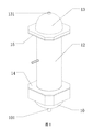
本発明は水浄化装置を提供し、図1が示すように、本発明の第1実施例によって提供される水浄化装置は、第1の圧力シリンダ10と、第1のシリンダ体11(図8参照)と、第2のシリンダ体12と、第2の圧力シリンダ13とを備えている。第1の圧力シリンダ10、第2のシリンダ体12と第2の圧力シリンダ13の順で接続されており、第1のシリンダ体11は第2のシリンダ体12内に収容されている。
The present invention provides a water purification apparatus. As shown in FIG. 1, the water purification apparatus provided by the first embodiment of the present invention includes a
図2が示すように、前記第1の圧力シリンダ10は第1の水流端104と、第1の排水端102を備えている。本実施例において、該第1の水流端104は、排水端102と相対して設置され、第1の水流端104は水の流れに供する開口を備えている。第1の吐水端102には水を流動させる第1の貫通孔101が設けられている。
As shown in FIG. 2, the
図8が示すように、前記第1のシリンダ体11は両側に開口を備え、中空の樽形をなして設置されている。
As shown in FIG. 8, the
前記第2のシリンダ体12は両側に開口を備え、中空の樽形をなして設置されている。
The
図3が示すように、前記第2の圧力シリンダ13は第2の水流端134と、第2の水排出端133を備えている。本実施例において、該第2の水流端134は、第2の排水端133と相対して設置され、第2の水流端134は水の流れに供する開口を備えている。第2の吐水端133には水を流動させる第2の貫通孔131が設けられている。
As shown in FIG. 3, the
前記第1の水流端104が前記第2のシリンダ体12の一端と連結し、前記第2のシリンダ体12の他端は前記第2の水流端134と連結する。前記第1のシリンダ体11は前記第2のシリンダ体12内に固定的に取り付けられており、前記第1のシリンダ体11と第2のシリンダ体12との間には第1の水流路123が形成されており、前記第1の水流路123は前記第1の圧力シリンダ10及び第2の圧力シリンダ13に連通しており、前記第2のシリンダ体12の外壁には前記第1の水流路123に連通する吸水口121が設けられており、該水浄化装置の外壁には、前記第1のシリンダ体11に連通する吐水管122が更に挿設されている。好ましくは、吸水口121は吐水管122と相対して設置される。
The first
水をろ過する前に、前記第1の貫通孔101が閉じた状態にあり、前記第2の貫通孔131が開いた状態にあって、該装置が汚物を排出するとき、前記第1の貫通孔101及び第2の貫通孔131がいずれも開く。
When the first through-
具体的には、前記水浄化装置はろ過時に立ったまま置くもので、すなわち前記第1の圧力シリンダ10が該水浄化装置の底部にあり、第2の圧力シリンダ13が該水浄化装置の頭部にあって、浄化待ちの水が前記吸水口121を通じて第1の水流路123に流れる時、ろ過待ちの水はまず第1の圧力シリンダ10内に流れ込み、水が多くなり、水位が次第に上がるにつれ、浄化待ちの水は水圧と前記第1の圧力シリンダ10の圧力作用で次第に第1のシリンダ体11内にあるろ材(例えば、活性炭と石英砂の混合物)に押され、ろ材にろ過された後、浄化待ちの水は前記吐水管122から排出される。ろ過する時、まずは第1の貫通孔101を閉じて、ろ過待ちの水は第1の水流路123での水位が次第に上がり、第2の圧力シリンダ13まで上がると、第2の貫通孔131から排出される。この過程において、浄化待ちの水における一部の土砂とほかの大粒の不純物は重力作用で前記第1の圧力シリンダ10の底部に堆積する一方、ろ材にろ過された不純物も食い止められて第1の圧力シリンダ10に残るところで、堆積と堆積していない土砂はすべて第1の貫通孔101を通じて排出できる。次に、浄化待ちの水における浮漂物が水の表面にあるゆえ、浄化待ちの水は第1の水流路123での水位が次第に第2の圧力シリンダ13までに上がると、前記浮漂物が第2の貫通孔131から排出される。
Specifically, the water purification device is left standing at the time of filtration, that is, the
本発明における水浄化装置は、第1の圧力シリンダ10と第2の圧力シリンダ13の圧力作用で、浄化待ちの水における土砂など大粒の不純物が第1の貫通孔101から排出され、浄化待ちの水における浮漂物が第2の貫通孔131から排出され、浄化待ちの水のろ過は充分なものとなり、水浄化が強化される。該水浄化装置によって、浮漂物によるろ材の汚染も緩和され、ろ材の耐用年数は大いに伸ばし、水浄化のコストが低下する。
In the water purification apparatus according to the present invention, large impurities such as earth and sand in the water waiting for purification are discharged from the first through-
更に、図4が示すように、前記第2のシリンダ体12と前記第1の圧力シリンダ10との間には、前記第1のシリンダ体11及び第2のシリンダ体12を前記第1の圧力シリンダ10に連結するための第1の連結手段14が更に設けられており、前記第1の連結手段14には前記水流路123を前記第1の圧力シリンダ10に連通するための第1の導流孔1431、及び前記第1のシリンダ体11を前記第1の圧力シリンダ10に連通するための第2の導流孔が設けられている(図には表示されていない)。
Further, as shown in FIG. 4, the
具体的に、前記第1の連結手段14は第1の連結板141を備えており、前記第1の連結板141には貫通孔が設けられており、前記貫通孔の周縁は該第1の連結板141の一つの板面とは反対となる方向で第1の円環状柱体142が延出しており、前記第1の円環状柱体142の前記第1の連結板141から離れた一端には該第1の円環状柱体142の端口を塞ぐ第1の封止板143が設けられており、前記第1の封止板143には前記第2の導流孔が設けられており、該第2の導流孔の周縁は該第1の封止板143の一つの板面とは反対となる方向で第2の円環状柱体144が延出しており、前記第2の円環状柱体144の周縁の第1の封止板143には前記第1の導流孔が1431更に設けられており、前記第1の円環状柱体142は前記第1の連結板141と前記第2の円環状柱体144との間に位置し、前記第1の円環状柱体142の口径は前記第2の円環状柱体144の口径よりも大きい。ここで説明すべきは、前記第1の円環状柱体142は好ましく前記第1の連結板144と垂直となっており、前記第2の円環状柱体144は好ましく前記第1の封止板143と垂直となっている。
Specifically, the first connecting
ここで、前記第1の連結板141は第1の圧力シリンダ10の第1の水流端104を塞ぎ、かつ第1の圧力シリンダ10と固定に連結する(例えばネジ山によって連結される)、前記第1のシリンダ体11には前記第2の円環状柱体144が被さるように設けられており、かつ第1のシリンダ体11は第2の円環状柱体144と密封的に連結しており、前記第2のシリンダ体12には前記第1の円環状柱体142が被さるように設けられており、かつ第2のシリンダ体12は第1の円環状柱体142と密封的に連結している。こうして、第1のシリンダ体11と、第2のシリンダ体12と、第1の圧力シリンダ10との連結が強化される。
Here, the first connecting
更に、前記第2の円環状柱体144の第1の封止板143から離れた一端には、該第2の円環状柱体144の端口を塞ぐ第2の封止板145が設けられており、前記第2の封止板145には増圧孔1451が設けられている。
Furthermore, a
前記ろ材は水に対する抵抗力が元々大きいゆえ、水ろ過の速度を上げるため、本実施例においては、増圧孔1451を設けることで水が前記ろ材の中により円滑に押し込まれるようにさせる。ろ過待ちの水が第1の圧力シリンダ10に入る時(第1の貫通孔101は閉じ、または一部が閉じる状態にある)、ろ過待ちの水が次第に第1の圧力シリンダ10によって押され、第1の水流端104を通じてろ材の中に押し込まれ、同じ圧力レベルでは、水がろ材に入る時の開口の面積が小さくなり、つまり水がろ材に入る時の圧力が上昇することで、水をろ材の中により円滑に流れ込ませることができ、水処理の強度と効率を上げる。
Since the filter medium originally has a high resistance to water, in order to increase the speed of water filtration, in this embodiment, the
更に、図2が示すように、前記第1の水流端104の第1の圧力シリンダ10の外壁に対応する位置には、前記第1の連結手段14に連結するための第1の補強手段103が被さるように設けられている。
Further, as shown in FIG. 2, the first reinforcing means 103 for connecting to the first connecting
具体的に、前記第1の連結手段14と第1の圧力シリンダ10との連結を強化するため、本実施例において、前記第1の水流端104の第1の圧力シリンダ10の外壁に対応する位置には、前記第1の連結手段14に連結するための第1の補強手段103が被さるように設けられている。前記第1の補強手段103は前記連結手段14とはネジ山によって連結される。第1の圧力シリンダ10と第1の連結手段14とは図2が示すネジ穴1031と図4が示すネジ穴1411を通じてネジ山によって連結される。
Specifically, in order to strengthen the connection between the first connecting
更に、図5が示すように、前記第2のシリンダ体12と前記第2の圧力シリンダ13との間には、前記第2のシリンダ体12を前記第2の圧力シリンダ13に連結するための第2の連結手段15が更に設けられており、前記第2の連結手段15には前記第1の水流路123を連通するための第3の導流孔153、及び前記第1のシリンダ体11を連通するための第4の導流孔151が設けられている。前記第2の水流端134の第2の圧力シリンダ13の外壁に対応する位置には、前記第2の連結手段15に連結するための第2の補強手段132が被さるように設けられている。
Further, as shown in FIG. 5, between the
図3が示すように、第2の補強手段132にはネジ穴135が設けられており、図5が示すように、第2の連結手段15における第3の導流孔153の周縁にはネジ穴152が設けられており、前記第2の圧力シリンダ13と前記第3の連結手段15とは前記ネジ穴135とネジ穴152を通じて、同じネジのネジ山によって連結される。
As shown in FIG. 3, the second reinforcing means 132 is provided with a
更に、図6、図7、図8および図9が示すように、前記吐水管122は前記第2のシリンダ体12を貫通して第1のシリンダ体に連通する。
Furthermore, as shown in FIGS. 6, 7, 8, and 9, the
具体的に、前記第1のシリンダ体11にろ材(石英砂と活性炭の混合物・活性炭)20が設けられている場合、ろ材20が前記第1シリンダ体の内部の間に第2の水流路201が形成されている。ろ材20が水をろ過する時は該ろ材20の両端からろ過待ちの水を押し流すもので、ろ過された水は該ろ材20の外周壁から排出され、かつ前記第2の水流路201に流れ込み、そして前記吐水管122から排出される。
Specifically, when a filter medium (a mixture of quartz sand and activated carbon / activated carbon) 20 is provided in the
更に、図10が示すように、前記第1のシリンダ体11内には二枚の仕切板110が設けられており、前記仕切板110には複数の貫通孔が設けられており、該仕切板110は前記第1のシリンダ体11の内部空間を、第1のシリンダ体11の半径方向に設けられた第1のろ過領域111と、一時貯留領域113及び第2のろ過領域112に仕切っており、前記吐水管122が前記第2のシリンダ体12の外壁を貫通して前記一時貯留領域113に連通している。
Further, as shown in FIG. 10, two
水における土砂またはほかの大粒の不純物をろ過する時、前記第1シリンダ体内にろ材を設ける必要がある。本実施例において、二枚の仕切板110は第1のシリンダ体11の半径方向に設けられた第1のろ過領域111と、一時貯留領域113及び第2のろ過領域112に仕切るように設けられており、前記第1のろ過領域111と第2のろ過領域112のいずれにもろ材(石英砂と活性炭の混合物・活性炭)が設けられており、水が第1のろ過領域111と第2のろ過領域112によってろ過されてから前記一時貯留領域113に流れこみ、該一時貯留領域113の水は前記吐水管122から排出される。浄化待ちの水における土砂など粒子物が多い場合、前記第2のろ過領域112におけるろ材が次第に塞がれ、ひいてはろ過機能を失う。こうなると、ろ材を交換する。なお、水における油脂が多い場合、前記第1のろ過領域111におけるろ材が次第に汚染され(無論、前記第1のろ過領域111におけるろ材は普通の水浄化装置と比べると、その耐用年数は大いに伸ばされている)、こうなった時はろ材を交換し、ろ過された水が二次汚染されるのを防止する。
When filtering earth and sand or other large impurities in water, it is necessary to provide a filter medium in the first cylinder. In this embodiment, the two
更に、図2が示すように、前記第1の圧力シリンダ10の内部空間の第1の水流端10の端面と平行となる横断面積が前記第1の水流端104から前記第1の貫通孔102に向かって徐々に小さくなっている。
Further, as shown in FIG. 2, the cross-sectional area parallel to the end surface of the first
具体的に、前記第1の圧力シリンダ10の内部空間は各種の形をなして設けられてもよく、それは例えば方形、筒形などであってもよい。しかし、第1の圧力シリンダ10によるろ過された不純物の排出を円滑化するため、本実施例において、前記第1の圧力シリンダ10の内部空間の第1の水流端104の端面と平行となる横断面積が前記第1の水流端104から前記第1の吐水端102に向かって徐々に小さくなっていて、したがって、水における不純物はろ過された後に第1の圧力シリンダ10の第1の貫通孔101を通して排出される。第1の圧力シリンダ10がこうして設けられていることで、第1の圧力シリンダ10の底部に死角が生じること無く、不純物が第1の圧力シリンダ10の底部に堆積することにはならない。
Specifically, the internal space of the
更に、図3が示すように、前記第2の圧力シリンダ13の内部空間の第2の水流端134の端面と平行となる横断面積が前記第2の水流端134から前記第2の貫通孔133に向かって徐々に小さくなっている。
Further, as shown in FIG. 3, the cross-sectional area parallel to the end surface of the second
具体的に、第2の圧力シリンダの頭部に浮漂物を排出するための第2の貫通孔131が設けられているとしても、第2の圧力シリンダの内部空間の頭部が並行して設けられるものだとすると、一部の浮漂物が直接排出されずに溜まっていることになって、溜まりすぎると、第2の貫通孔131が塞がれかねる。本実施例において、前記第2の圧力シリンダ13の内部空間の第2の水流端134の端面と平行となる横断面積が前記第2の水流端134から前記第2の貫通孔133に向かって徐々に小さくなっていて、それは例えば、第2の圧力シリンダ13の内部空間が錐形をなして設けられてもよく、第2の圧力シリンダ13の平滑な内壁は浮漂物を排出する時に誘導物として機能し、浮漂物が迅速に排出されるようにさせる。
Specifically, even if the second pressure hole is provided with the second through-
更に、前記第1の貫通孔101には第1の汚物排出管が挿設されており、前記第2の貫通孔131には第2の汚物排出管が挿設されており、前記第1の汚物排出管に第1のバルブが設けられていて、第2の汚物排出管には第2のバルブが設けられている。
Further, a first filth discharge pipe is inserted into the first through
水処理の速度は第1のバルブと第2のバルブを調整することで制御されるもので、該水浄化装置内部の圧力も第1のバルブと第2のバルブを調整することで制御されるものである。例えば、我が国の北部の水には多くの土砂が含まれており、該水浄化装置でこういう水をろ過する場合は、第2のバルブを調整することで第1の圧力シリンダ10による汚水排出の速度を速めることができる。沿岸部の水は塩度が高く、該水浄化装置でこういう水をろ過する場合は、第1のバルブと第2のバルブを調整することで第1の圧力シリンダ10と第2のシリンダ13による排出速度を速め、該水浄化装置内部の圧力全体を強化し、したがって浄化待ちの水のろ過速度を速めることができる。
The water treatment speed is controlled by adjusting the first valve and the second valve, and the pressure inside the water purification apparatus is also controlled by adjusting the first valve and the second valve. Is. For example, the water in the northern part of Japan contains a lot of earth and sand. When such water is filtered by the water purification device, the second pressure is adjusted by adjusting the second valve. You can speed up. The water in the coastal area has a high salinity, and when such water is filtered by the water purification device, the
石英砂と活性炭の混合物による土砂、コロイド体など粒の大きい不純物と油脂のろ過試験:
浄化待ちの水を該水浄化装置の吸水口121に流れ込ませたあと、吸水による圧力と第1の圧力シリンダ10と第2のシリンダ13の圧力作用で、該水浄化装置では底部と頭部の圧力による調整で、水における土砂、汚泥、汚染物質、粒子、コロイド体は石英砂と活性炭の混合物・活性炭によって分離され、錐体をなしている第1の圧力シリンダ10の汚物排出口まで堆積して、処理された水は不純物が隔離され、浄水口から流出して浄水となる。測定したところ、本水浄化装置による土砂、コロイド体など粒の大きい不純物の除去率が80%と高く、油脂の除去率が100%となる。
Filtration test of large-grained impurities such as earth and sand, colloids and fats and oils with a mixture of quartz sand and activated carbon:
After the water waiting for purification flows into the
上記における実施例は本発明の好ましい実施例であったが、本発明を何ら限定するものではない、本発明の明細書と添付図面を持って作成した同等な効果を持つ構造または同等な効果を持つプロセス、もしくはそれらを直接または間接的にほかの関連技術分野に運用する行為は、いずれも本発明の特許保護に属するものとなる。以下における実施例は、当業者の本発明に対する更なる理解を助力するが、本発明を何ら限定するものではない。
The above embodiment is a preferred embodiment of the present invention, but does not limit the present invention. The structure having the same effect or the equivalent effect created with the specification of the present invention and the attached drawings is not limited. Any of the processes possessed or the act of operating them directly or indirectly in other related technical fields belong to the patent protection of the present invention. The following examples help those skilled in the art to further understand the present invention, but do not limit the present invention in any way.
Claims (10)
前記第1のシリンダ体の対向する両端は開口を有し、かつ中空をなして設置されており、該第1のシリンダ体は水をろ過するろ過材料を設置するためのものであり、前記第2のシリンダ体の対向する両端は開口を有し、かつ中空をなして設置されており、前記第1の圧力シリンダは第1の水流端及び第1の吐水端を含み、前記第1の水流端には水を流動させる開口が設けられており、前記第1の吐水端には水を流動させる第1の貫通孔が設けられており、前記第2の圧力シリンダは第2の水流端及び第2の吐水端を含み、かつ中空をなして設置されており、前記第2の水流端には水を流動させる開口が設けられており、前記第2の吐水端には水を流動させる第2の貫通孔が設けられており、
前記第1の水流端は前記第2のシリンダ体の一端に接続されており、前記第2のシリンダ体の他端は前記第2の水流端に接続されており、前記第1のシリンダ体と第2のシリンダ体との間には第1の水流路が形成されており、前記第1の水流路は前記第1の圧力シリンダ及び第2の圧力シリンダに連通しており、前記第2のシリンダ体の外壁には前記第1の水流路に連通する吸水口が設けられており、前記第2のシリンダ体の外壁には、前記第1のシリンダ体に連通する吐水管が更に挿設されており、
該水浄化装置は水をろ過する前に、前記第1の貫通孔が閉じた状態にあり、前記第2の貫通孔が開いた状態にあって、該装置が汚物を排出するとき、前記第1の貫通孔及び第2の貫通孔がいずれも開く、水浄化装置。 A water purification apparatus, comprising: a first pressure cylinder, a second pressure cylinder, a first cylinder body, and a second cylinder body, wherein the first pressure cylinder The second cylinder body and the second pressure cylinder are connected in this order, and the first cylinder body is housed in the second cylinder body,
Opposite ends of the first cylinder body have openings and are installed in a hollow space, and the first cylinder body is for installing a filtering material for filtering water, The opposite ends of the cylinder body of 2 have an opening and are installed in a hollow shape, and the first pressure cylinder includes a first water flow end and a first water discharge end, and the first water flow An opening through which water flows is provided at the end, a first through hole through which water flows is provided at the first water discharge end, and the second pressure cylinder has a second water flow end and The second water discharge end includes a second water discharge end and is installed in a hollow shape. The second water flow end is provided with an opening through which water flows, and the second water discharge end has a second flow through which water flows. 2 through holes are provided,
The first water flow end is connected to one end of the second cylinder body, the other end of the second cylinder body is connected to the second water flow end, and the first cylinder body and A first water flow path is formed between the second cylinder body, the first water flow path is in communication with the first pressure cylinder and the second pressure cylinder, The outer wall of the cylinder body is provided with a water inlet that communicates with the first water flow path, and a water discharge pipe that communicates with the first cylinder body is further inserted into the outer wall of the second cylinder body. And
The water purification device is in a state where the first through hole is closed before the water is filtered, and the second through hole is opened. The water purification apparatus in which both the first through hole and the second through hole are opened.
A first filth discharge pipe is inserted into the first through-hole, and a second filth discharge pipe is inserted into the second through-hole, and the first filth discharge pipe and The water purification apparatus according to any one of claims 1 to 5, wherein each of the second filth discharge pipes is provided with a water flow control valve.
Applications Claiming Priority (3)
| Application Number | Priority Date | Filing Date | Title |
|---|---|---|---|
| CN201410723244.2A CN104492131B (en) | 2014-12-02 | 2014-12-02 | Water purification installation |
| CN201410723244.2 | 2014-12-02 | ||
| PCT/CN2015/085724 WO2016086680A1 (en) | 2014-12-02 | 2015-07-31 | Water purification device |
Publications (1)
| Publication Number | Publication Date |
|---|---|
| JP2018501087A true JP2018501087A (en) | 2018-01-18 |
Family
ID=52933635
Family Applications (1)
| Application Number | Title | Priority Date | Filing Date |
|---|---|---|---|
| JP2017529087A Ceased JP2018501087A (en) | 2014-12-02 | 2015-07-31 | Water purification equipment |
Country Status (9)
| Country | Link |
|---|---|
| US (1) | US20170326477A1 (en) |
| EP (1) | EP3228596A4 (en) |
| JP (1) | JP2018501087A (en) |
| CN (1) | CN104492131B (en) |
| BR (1) | BR112017011675A2 (en) |
| CA (1) | CA2969354A1 (en) |
| HK (1) | HK1209078A1 (en) |
| IL (1) | IL252546A0 (en) |
| WO (1) | WO2016086680A1 (en) |
Cited By (2)
| Publication number | Priority date | Publication date | Assignee | Title |
|---|---|---|---|---|
| JP2017536233A (en) * | 2014-12-02 | 2017-12-07 | シェンジェン ボル エンバイロメンタル テクノロジー カンパニー リミテッド | Water purification apparatus and water filtration method using the water purification apparatus |
| JP2017536234A (en) * | 2014-12-02 | 2017-12-07 | シェンジェン ボル エンバイロメンタル テクノロジー カンパニー リミテッド | Water purification apparatus and water filtration method using the water purification apparatus |
Families Citing this family (3)
| Publication number | Priority date | Publication date | Assignee | Title |
|---|---|---|---|---|
| CN104492131B (en) * | 2014-12-02 | 2016-01-13 | 深圳市博儒环境技术有限公司 | Water purification installation |
| CN106809907B (en) * | 2016-12-25 | 2020-04-21 | 重庆杰鑫直饮水净化设备有限公司 | A clarification plant for drinking water |
| RU192556U1 (en) * | 2019-05-22 | 2019-09-23 | федеральное государственное бюджетное образовательное учреждение высшего образования "Белгородский государственный технологический университет им. В.Г. Шухова" | HEAD WATER FILTER FOR CLEANING WATER |
Citations (6)
| Publication number | Priority date | Publication date | Assignee | Title |
|---|---|---|---|---|
| JPS52123547A (en) * | 1976-04-07 | 1977-10-17 | Jiyuuichi Kashiwamoto | Deeoiler |
| JPH08168653A (en) * | 1994-12-15 | 1996-07-02 | Hitachi Ltd | Reverse osmosis membrane type water purifying device |
| JP2000042382A (en) * | 1998-08-04 | 2000-02-15 | Nikkiso Co Ltd | Separation membrane and filter |
| JP2011509821A (en) * | 2008-01-16 | 2011-03-31 | グラハム,ウィリアム | Distribution board to treat water by reverse osmosis |
| JP2017536233A (en) * | 2014-12-02 | 2017-12-07 | シェンジェン ボル エンバイロメンタル テクノロジー カンパニー リミテッド | Water purification apparatus and water filtration method using the water purification apparatus |
| JP2017536234A (en) * | 2014-12-02 | 2017-12-07 | シェンジェン ボル エンバイロメンタル テクノロジー カンパニー リミテッド | Water purification apparatus and water filtration method using the water purification apparatus |
Family Cites Families (11)
| Publication number | Priority date | Publication date | Assignee | Title |
|---|---|---|---|---|
| US4147631A (en) * | 1977-09-23 | 1979-04-03 | Teledyne Industries, Inc. | Water control and distribution apparatus |
| CN1041337A (en) * | 1988-09-29 | 1990-04-18 | 深圳市新世纪饮水科技有限公司 | Household multifunctional water-drinking device |
| CN2466138Y (en) * | 2001-01-21 | 2001-12-19 | 李从民 | Drinking water purifier |
| CN2641025Y (en) * | 2003-09-12 | 2004-09-15 | 深圳市诚德来实业有限公司 | Fast matching water purifier |
| ES1059225Y (en) * | 2005-01-04 | 2005-07-01 | Roca Salvador Ros | PERFECTED SELF-CLEANING FILTER FOR AGRICULTURAL IRRIGATION WATERS. |
| KR100949823B1 (en) * | 2009-07-01 | 2010-03-30 | 이정호 | Apparatus for waste water treatment |
| KR101235351B1 (en) * | 2012-02-14 | 2013-02-20 | 김종인 | Waste water treatment apparatus |
| CN102935304A (en) * | 2012-12-07 | 2013-02-20 | 许国昌 | Dual-purpose water filtering purifier |
| CN103373780B (en) * | 2013-05-31 | 2015-07-29 | 福建方明环保科技股份有限公司 | A kind of device for purifying potable water and method |
| CN104492131B (en) * | 2014-12-02 | 2016-01-13 | 深圳市博儒环境技术有限公司 | Water purification installation |
| CN204310854U (en) * | 2014-12-02 | 2015-05-06 | 深圳市博儒环境技术有限公司 | Water-purification plant |
-
2014
- 2014-12-02 CN CN201410723244.2A patent/CN104492131B/en active Active
-
2015
- 2015-07-31 EP EP15865247.9A patent/EP3228596A4/en not_active Withdrawn
- 2015-07-31 US US15/531,534 patent/US20170326477A1/en not_active Abandoned
- 2015-07-31 CA CA2969354A patent/CA2969354A1/en not_active Abandoned
- 2015-07-31 BR BR112017011675A patent/BR112017011675A2/en not_active IP Right Cessation
- 2015-07-31 JP JP2017529087A patent/JP2018501087A/en not_active Ceased
- 2015-07-31 WO PCT/CN2015/085724 patent/WO2016086680A1/en active Application Filing
- 2015-09-24 HK HK15109421.3A patent/HK1209078A1/en not_active IP Right Cessation
-
2017
- 2017-05-28 IL IL252546A patent/IL252546A0/en unknown
Patent Citations (6)
| Publication number | Priority date | Publication date | Assignee | Title |
|---|---|---|---|---|
| JPS52123547A (en) * | 1976-04-07 | 1977-10-17 | Jiyuuichi Kashiwamoto | Deeoiler |
| JPH08168653A (en) * | 1994-12-15 | 1996-07-02 | Hitachi Ltd | Reverse osmosis membrane type water purifying device |
| JP2000042382A (en) * | 1998-08-04 | 2000-02-15 | Nikkiso Co Ltd | Separation membrane and filter |
| JP2011509821A (en) * | 2008-01-16 | 2011-03-31 | グラハム,ウィリアム | Distribution board to treat water by reverse osmosis |
| JP2017536233A (en) * | 2014-12-02 | 2017-12-07 | シェンジェン ボル エンバイロメンタル テクノロジー カンパニー リミテッド | Water purification apparatus and water filtration method using the water purification apparatus |
| JP2017536234A (en) * | 2014-12-02 | 2017-12-07 | シェンジェン ボル エンバイロメンタル テクノロジー カンパニー リミテッド | Water purification apparatus and water filtration method using the water purification apparatus |
Cited By (2)
| Publication number | Priority date | Publication date | Assignee | Title |
|---|---|---|---|---|
| JP2017536233A (en) * | 2014-12-02 | 2017-12-07 | シェンジェン ボル エンバイロメンタル テクノロジー カンパニー リミテッド | Water purification apparatus and water filtration method using the water purification apparatus |
| JP2017536234A (en) * | 2014-12-02 | 2017-12-07 | シェンジェン ボル エンバイロメンタル テクノロジー カンパニー リミテッド | Water purification apparatus and water filtration method using the water purification apparatus |
Also Published As
| Publication number | Publication date |
|---|---|
| IL252546A0 (en) | 2017-07-31 |
| HK1209078A1 (en) | 2016-03-24 |
| EP3228596A4 (en) | 2018-08-22 |
| EP3228596A1 (en) | 2017-10-11 |
| WO2016086680A1 (en) | 2016-06-09 |
| CN104492131B (en) | 2016-01-13 |
| CN104492131A (en) | 2015-04-08 |
| CA2969354A1 (en) | 2016-06-09 |
| BR112017011675A2 (en) | 2018-01-02 |
| US20170326477A1 (en) | 2017-11-16 |
Similar Documents
| Publication | Publication Date | Title |
|---|---|---|
| JP2018501087A (en) | Water purification equipment | |
| CN102745788A (en) | Automatic integrated coagulation clarification and filtering device | |
| JP2017536233A (en) | Water purification apparatus and water filtration method using the water purification apparatus | |
| JP2017536234A (en) | Water purification apparatus and water filtration method using the water purification apparatus | |
| CN103239905A (en) | Siphon type valveless filtering pool | |
| CN205461213U (en) | High -efficient gas -liquid separation sewage treatment automatic filtration device | |
| CN201728065U (en) | Membrane filtration device | |
| CN201912802U (en) | Radial-flow sludge sedimentation filter tank with sludge layer | |
| CN114470892A (en) | Hydraulic spiral-flow type backwashing filter device and method | |
| CN204745769U (en) | Gravity type valveless filter | |
| CN210331861U (en) | Sewage filtering tank for emission reduction and environmental protection of municipal sewage | |
| CN104860430A (en) | Efficient sewage filtering device | |
| CN204779097U (en) | High -efficient contaminated water filtration apparatus | |
| CN202466820U (en) | Novel oil-water separator | |
| KR20100047032A (en) | Apparatus for treating rainwater | |
| CN210621873U (en) | Biological safety protection underground sewage system | |
| CN204752394U (en) | Sand filter unit | |
| CN204310854U (en) | Water-purification plant | |
| CN204779098U (en) | High -efficient sewage pretreatment device | |
| JP2013086027A (en) | Cyclone type filtering device | |
| CN212334815U (en) | Industrial production abandonment peculiar smell filtering ponds | |
| CN204093097U (en) | Vertical-flow tube settler | |
| CN204779096U (en) | Sewage filtering equipment | |
| CN210584516U (en) | Silencing device for mine water advanced treatment system | |
| CN202061479U (en) | Water purification system with sand-water automatic separating function |
Legal Events
| Date | Code | Title | Description |
|---|---|---|---|
| A131 | Notification of reasons for refusal |
Free format text: JAPANESE INTERMEDIATE CODE: A131 Effective date: 20180601 |
|
| A977 | Report on retrieval |
Free format text: JAPANESE INTERMEDIATE CODE: A971007 Effective date: 20180530 |
|
| A521 | Request for written amendment filed |
Free format text: JAPANESE INTERMEDIATE CODE: A523 Effective date: 20180720 |
|
| A01 | Written decision to grant a patent or to grant a registration (utility model) |
Free format text: JAPANESE INTERMEDIATE CODE: A01 Effective date: 20180905 |
|
| A045 | Written measure of dismissal of application [lapsed due to lack of payment] |
Free format text: JAPANESE INTERMEDIATE CODE: A045 Effective date: 20190124 |