JP2018203251A - Folding type rear view mirror assembly actuator mechanism - Google Patents
Folding type rear view mirror assembly actuator mechanism Download PDFInfo
- Publication number
- JP2018203251A JP2018203251A JP2018109136A JP2018109136A JP2018203251A JP 2018203251 A JP2018203251 A JP 2018203251A JP 2018109136 A JP2018109136 A JP 2018109136A JP 2018109136 A JP2018109136 A JP 2018109136A JP 2018203251 A JP2018203251 A JP 2018203251A
- Authority
- JP
- Japan
- Prior art keywords
- actuator mechanism
- rear view
- view mirror
- torque
- driving
- Prior art date
- Legal status (The legal status is an assumption and is not a legal conclusion. Google has not performed a legal analysis and makes no representation as to the accuracy of the status listed.)
- Pending
Links
Images


Classifications
-
- B—PERFORMING OPERATIONS; TRANSPORTING
- B60—VEHICLES IN GENERAL
- B60R—VEHICLES, VEHICLE FITTINGS, OR VEHICLE PARTS, NOT OTHERWISE PROVIDED FOR
- B60R1/00—Optical viewing arrangements; Real-time viewing arrangements for drivers or passengers using optical image capturing systems, e.g. cameras or video systems specially adapted for use in or on vehicles
- B60R1/02—Rear-view mirror arrangements
- B60R1/06—Rear-view mirror arrangements mounted on vehicle exterior
- B60R1/062—Rear-view mirror arrangements mounted on vehicle exterior with remote control for adjusting position
- B60R1/07—Rear-view mirror arrangements mounted on vehicle exterior with remote control for adjusting position by electrically powered actuators
- B60R1/074—Rear-view mirror arrangements mounted on vehicle exterior with remote control for adjusting position by electrically powered actuators for retracting the mirror arrangements to a non-use position alongside the vehicle
-
- B—PERFORMING OPERATIONS; TRANSPORTING
- B60—VEHICLES IN GENERAL
- B60R—VEHICLES, VEHICLE FITTINGS, OR VEHICLE PARTS, NOT OTHERWISE PROVIDED FOR
- B60R1/00—Optical viewing arrangements; Real-time viewing arrangements for drivers or passengers using optical image capturing systems, e.g. cameras or video systems specially adapted for use in or on vehicles
- B60R1/02—Rear-view mirror arrangements
- B60R1/06—Rear-view mirror arrangements mounted on vehicle exterior
- B60R1/076—Rear-view mirror arrangements mounted on vehicle exterior yieldable to excessive external force and provided with an indexed use position
Abstract
Description
本開示は、一般に、動力で動く乗り物用のリアビューミラーアセンブリに関し、より詳細には、動力で動く乗り物用の折り畳み式リアビューミラーアセンブリ用のアクチュエータ機構に関する。 The present disclosure relates generally to rear view mirror assemblies for powered vehicles, and more particularly to actuator mechanisms for folding rear view mirror assemblies for powered vehicles.
(背景)
動力で動く乗り物用の折り畳み式リアビューミラーアセンブリは、例えば、非駆動位置と駆動位置との間で電動機を介して駆動される。電動機は、通常、ミラーハウジングの内部に取り付けられ、ミラーハウジングはまた、順番にその中にミラー板を収容する。電動機が作動されると、ミラーハウジングは、動力で動く乗り物に、通常は動力で動く乗り物のボディに、取り付けられたミラーベース又は固定部の周りを回転する。このようにして、ミラーハウジングは、少なくとも上述の2つの安定した位置、すなわち、パーク位置及びドライビング位置にそれぞれ対応する上記の非駆動位置及び駆動位置に配置することができる。ミラーハウジングとミラーベース又は固定部との間に作用するように、通常、圧縮バネが、取り付けられている。
(background)
A foldable rear view mirror assembly for a powered vehicle is driven, for example, via an electric motor between a non-drive position and a drive position. The electric motor is usually mounted inside the mirror housing, which in turn houses the mirror plate therein. When the motor is activated, the mirror housing rotates around a mirror base or fixture attached to a powered vehicle, usually a powered vehicle body. In this way, the mirror housing can be arranged in at least the above-mentioned two stable positions, that is, the above-mentioned non-driving position and driving position corresponding to the park position and the driving position, respectively. A compression spring is usually attached to act between the mirror housing and the mirror base or fixed part.
ミラーベース又は固定部には、ミラーハウジングに形成された対応する歯が回転するときにそれと協働するように適合された歯が設けられている。ミラーベースの歯とミラーハウジングの歯との両方が傾斜面を画定し、これらの傾斜面は、上記圧縮バネと協働して、上記の少なくとも2つの安定した位置、すなわち上述の非駆動位置と駆動位置との間のミラーベースに対するミラーハウジングの意図せぬ折り畳みに対する機械的抵抗を提供する。例えば、ミラーハウジングが駆動位置に配置されてドライバに対して略後方視野を提供する車両の走行中に、例えば風の状態のために、駆動位置から非駆動位置への意図せぬ折り畳みが生じることがある。 The mirror base or fixed part is provided with teeth adapted to cooperate with corresponding teeth formed on the mirror housing as they rotate. Both the mirror base teeth and the mirror housing teeth define inclined surfaces, which cooperate with the compression springs to achieve the at least two stable positions, i.e., the non-driven position described above. Provides mechanical resistance against unintentional folding of the mirror housing relative to the mirror base between drive positions. For example, unintentional folding from the drive position to the non-drive position may occur during travel of the vehicle where the mirror housing is located in the drive position and provides a substantially rear view to the driver, for example due to wind conditions There is.
電動機が作動しない又は電源の故障が生じ、且つ、ユーザがリアビューミラーハウジングを駆動位置に移動させたいとき、ユーザは、手動でトルクをミラーハウジングに加える必要があり、これにより歯の噛み合いを克服することができる。なお、ユーザによって手動で加えられるトルクは、通常、電動機によって加えられるトルクよりも高い。 When the motor does not work or a power failure occurs and the user wants to move the rearview mirror housing to the drive position, the user must manually apply torque to the mirror housing, thereby overcoming tooth meshing be able to. Note that the torque manually applied by the user is usually higher than the torque applied by the electric motor.
ミラーハウジングがミラー回転軸のまわりでミラーベースに対して手動で作動されると、ミラーベースの歯とミラーハウジングの歯とが互いに対して移動する。このような相対移動の間、上記の歯のそれぞれの傾斜面は、ミラーハウジングとミラーベースの回転方向に応じて、ミラーハウジングをミラーベースに対して上昇又は下降させることができる。 When the mirror housing is manually actuated relative to the mirror base about the mirror rotation axis, the mirror base teeth and the mirror housing teeth move relative to each other. During such relative movement, each inclined surface of the teeth can raise or lower the mirror housing relative to the mirror base depending on the direction of rotation of the mirror housing and the mirror base.
手動で回転されるようにミラーハウジングをミラーベースに対して下方へ移動することは、ミラーハウジングを、圧縮バネを圧縮するミラーベースに向かって移動させることになる。ミラーハウジングのミラーベースへのこの動きにおいて、圧縮バネは、その相対的な角度位置を決定するためにミラーハウジングの回転に対抗する。手動で反対方向に回転されるときミラーベースに対するミラーハウジングの上方移動は、ミラーハウジングをミラーベースから遠ざけて圧縮バネを解放する。上記の歯及び傾斜面の構成はまた、ミラーハウジングの上述の所定の駆動及び非駆動位置を規定する。 Moving the mirror housing downward relative to the mirror base to be manually rotated will cause the mirror housing to move toward the mirror base that compresses the compression spring. In this movement of the mirror housing to the mirror base, the compression spring counteracts the rotation of the mirror housing to determine its relative angular position. The upward movement of the mirror housing relative to the mirror base when manually rotated in the opposite direction moves the mirror housing away from the mirror base and releases the compression spring. The tooth and ramp configuration also defines the predetermined drive and non-drive positions of the mirror housing.
上記折り畳み式リアビューミラーアセンブリの一例は、US2007035862に開示されている。この文献に教示されているリアビューミラーアセンブリは、ベースプレートを備えるヒンジアクチュエータと、協働する停止部を備えたミラー支持体と、を含んでいる。第1組の協働する停止部を介してミラー支持体と協働することができ、且つ第2組の協働する停止部を介してベースプレートと協働することができる結合リングが配置され、その結果、結合リングの第1角度において、第1組の停止部の協働により、バネ力が伝達され、第2角度では、第2組の停止部の協働によるバネ力がベースプレートに伝達される。 An example of such a folding rear view mirror assembly is disclosed in US2007035862. The rear view mirror assembly taught in this document includes a hinge actuator with a base plate and a mirror support with cooperating stops. A coupling ring is arranged that can cooperate with the mirror support via a first set of cooperating stops and can cooperate with the base plate via a second set of cooperating stops, As a result, at the first angle of the coupling ring, the spring force is transmitted by the cooperation of the first set of stop portions, and at the second angle, the spring force by the cooperation of the second set of stop portions is transmitted to the base plate. The
しかしながら、ミラーハウジングを手動で作動させる場合、例えば、リアビューミラーアセンブリを駆動するために電動機の故障が生じた場合、又はユーザがミラーハウジングを手動で駆動したい場合であっても、ミラーベースの歯とミラーハウジングの歯とが相対的に移動しているので、ミラーハウジングの上述した所定の駆動位置及び非駆動位置が、十分に達成されないことがある。これは、ミラー板が、動力で動く乗り物を駆動するための駆動位置に適切に配置できない結果を生じる場合がある。 However, when manually operating the mirror housing, for example, if a motor failure occurs to drive the rearview mirror assembly, or if the user wants to drive the mirror housing manually, the mirror base teeth and Due to the relative movement of the teeth of the mirror housing, the aforementioned predetermined drive and non-drive positions of the mirror housing may not be fully achieved. This may result in the mirror plate not being properly placed in the drive position for driving a vehicle that is powered.
国際公開第2012047104号パンフレットは、パーク位置と、ドライビング位置と、ベースに対するフォールドオーバー(fold-over)位置との間で旋回可能に調整可能なハウジングを含む調整器具を備える車両用のリアビューミラーアセンブリに関する。調整器具は、ハウジング内に設けられた電気駆動部と、電気駆動部と結合するための駆動リングと、をさらに備える。 WO20120407104 relates to a rear view mirror assembly for a vehicle comprising an adjustment device comprising a housing that is adjustable pivotably between a park position, a driving position and a fold-over position relative to the base. . The adjustment tool further includes an electric drive provided in the housing and a drive ring for coupling with the electric drive.
このようなリアビューミラーアセンブリは、アセンブリの手動駆動及び動力駆動を行い、さらにミラーハウジングを所与の位置に係止するために互いに相互作用する多数の構成要素からなる。しかしながら、この文献に記載されたリアビューミラーアセンブリは、所与の構成要素が取り外された場合、ミラーアセンブリは、手動モード及び動力モードの両方で動作せず、駆動位置において上記の係止位置に駆動することができないという欠点を有する。 Such a rearview mirror assembly consists of a number of components that interact with each other to provide manual and power drive of the assembly and to lock the mirror housing in a given position. However, the rear view mirror assembly described in this document does not operate in both manual mode and power mode when a given component is removed and is driven to the locked position in the drive position. Has the disadvantage of not being able to.
(概要)
上記の欠点は、折り畳み式リアビューミラーアセンブリのための本アクチュエータ機構によって克服され、また、本アクチュエータ機構によって重要な利点も得ることができる。
(Overview)
The above disadvantages are overcome by the present actuator mechanism for the folding rear view mirror assembly, and significant advantages can also be obtained by the present actuator mechanism.
具体的には、本アクチュエータ機構は、第1部材と、第2部材と、第3部材と、を備える。 Specifically, the actuator mechanism includes a first member, a second member, and a third member.
アクチュエータ機構の第1部材は、リアビューミラーハウジングと関連し、それと共に移動可能である。例えば、第1部材は、リアビューミラーハウジングに取り付けられてもよく、或いは、リアビューミラーハウジングと一体的に形成されてもよく、第1部材は、リアビューミラーハウジングと共に回転するようになっている。リアビューミラーハウジングは、動力で動く乗り物折り畳み式リアビューミラーアセンブリの一部であり、その中にミラー板を収容するように構成されている。リアビューミラーハウジングは、軸(例えば、動力で動く乗り物の固定部に対して略垂直な軸)を中心に旋回可能である。動力で動く乗り物の固定部は、例えば、動力で動く乗り物のボディ又はその一部であってもよい。 A first member of the actuator mechanism is associated with the rear view mirror housing and is movable therewith. For example, the first member may be attached to the rear view mirror housing, or may be formed integrally with the rear view mirror housing, and the first member rotates with the rear view mirror housing. The rear view mirror housing is part of a powered vehicle foldable rear view mirror assembly and is configured to receive a mirror plate therein. The rear-view mirror housing is pivotable about an axis (for example, an axis that is substantially perpendicular to the fixed part of the vehicle that is driven by power). The fixed part of the vehicle that moves by power may be, for example, the body of the vehicle that moves by power or a part thereof.
本アクチュエータ機構の第3部材は、第1部材に向かう方向及び第1部材から離れる方向に、移動するように構成される。例えば、第3部材は、第1部材の方に、及び第1部材から離れるように、上記の略垂直な軸に沿った方向に移動するように適合されてもよい。第3部材の第1部材に対するこのような移動を行うために、以下でさらに説明するように、第3部材に、多数の係止部を形成することができる。 The third member of the actuator mechanism is configured to move in a direction toward the first member and in a direction away from the first member. For example, the third member may be adapted to move in a direction along the substantially vertical axis as described above and away from the first member. In order to perform such movement of the third member relative to the first member, a number of locking portions can be formed in the third member, as will be further described below.
上記の非駆動位置と駆動位置との間で電動機を介してリアビューミラーハウジングは回転が駆動されると、第3部材は、第1部材から離間し、且つ、固定部に係止されたまま回転しない。リアビューミラーを動作させると、例えば、リアビューミラーアセンブリを駆動するための電動機の故障が発生し、ユーザによって自動的にではなく手動でリアビューミラーハウジングを回転することができない場合、第3部材は、所定の位置に連動するように第1部材に向かって移動する。第1部材に対する第3部材の駆動は、後述するように、第2部材によって行われる。 When the rear view mirror housing is driven to rotate between the non-drive position and the drive position via the electric motor, the third member is separated from the first member and rotates while being locked to the fixed portion. do not do. When the rear-view mirror is operated, for example, when a motor for driving the rear-view mirror assembly fails, and the user cannot rotate the rear-view mirror housing manually instead of automatically, the third member is It moves toward the first member so as to be interlocked with the position. The driving of the third member relative to the first member is performed by the second member, as will be described later.
本アクチュエータ機構の第3部材は、有益には、機構の別個の部品であり、折り畳み式リアビューミラーアセンブリに容易に取り付けられたり、取り外されたりすることができることに留意されたい。第3部材が取り外された場合、折り畳み式のリアビューミラーアセンブリは、どのようにしても機能する。 It should be noted that the third member of the present actuator mechanism is beneficially a separate part of the mechanism and can be easily attached to or removed from the folding rear view mirror assembly. When the third member is removed, the foldable rear view mirror assembly functions in any way.
アクチュエータ機構の第2部材は、第1部材が最大所定トルクを超えない第1トルクだけ回転されるとき、動力で動く乗り物の固定部に回転が係止されるように適合されている。第1トルクは、第1部材が電動機によって駆動されるときに加えられるトルクに対応する。アクチュエータ機構の第2部材はまた、第1部材が上記の最大所定トルクを超える第2トルクで回転するときに、第1部材に向かう上記の方向に、上述のように第3部材を移動させるように適合される。第2トルクは、第1部材が手動で駆動されるときに加えられるトルクに対応し、その場合、第1部材は第2部材に対して回転しない、すなわち、それらは一緒に回転する。最大所定トルクは、ミラーハウジングが手動で駆動されるときに第2部材を固定部から係止解除するのに必要なトルクに対応する。 The second member of the actuator mechanism is adapted to be locked to rotation on a stationary portion of the vehicle that is powered by the first member when the first member is rotated by a first torque that does not exceed a maximum predetermined torque. The first torque corresponds to the torque applied when the first member is driven by the electric motor. The second member of the actuator mechanism also moves the third member as described above in the direction toward the first member when the first member rotates with the second torque exceeding the maximum predetermined torque. Is adapted to. The second torque corresponds to the torque applied when the first member is driven manually, in which case the first member does not rotate relative to the second member, i.e. they rotate together. The maximum predetermined torque corresponds to the torque required to unlock the second member from the fixed portion when the mirror housing is driven manually.
第2部材が固定部から係止解除されると、第1部材と第3部材は、第1部材の所定の位置で互いに連動することができ、第1部材と第2部材は一緒に回転する。第1部材と第3部材が相互に連動する上記の所定の位置は、例えば、動力で動く乗り物を駆動するためのリアビューミラーの駆動位置に対応することができる。 When the second member is unlocked from the fixed portion, the first member and the third member can interlock with each other at a predetermined position of the first member, and the first member and the second member rotate together. . The predetermined position at which the first member and the third member are interlocked with each other can correspond to, for example, a driving position of a rear view mirror for driving a vehicle that moves by power.
第3部材は、第2部材と同心に配置されることが好ましい。他の配置も可能である。 The third member is preferably arranged concentrically with the second member. Other arrangements are possible.
本明細書で使用されるように、第1トルクは、リアビューミラーハウジングを回転させるためのリアビューミラーアセンブリの通常動作時に電動機によって加えられるトルクを指し、第2トルクは、リアビューミラーを手動で回転させるためにユーザによって手動で加えられるトルクを指すことができる。第1トルクの値は、2Nm〜10Nm程度(例えば5Nm)であり、一方、第2トルクの値は、8Nm〜30Nm程度(例えば14Nm)である。もちろん、他のトルク値も可能である。最大所定トルクは、リアビューミラーハウジングを固定部に対して回転させ、電力を使用せずに固定部から第2部材を係止解除するために克服すべきトルクに対応する。最大所定トルクは、後述するリアビューミラーアセンブリの係止部の構成に依存する。 As used herein, the first torque refers to the torque applied by the motor during normal operation of the rear view mirror assembly for rotating the rear view mirror housing, and the second torque manually rotates the rear view mirror. Therefore, it can refer to the torque manually applied by the user. The value of the first torque is about 2 Nm to 10 Nm (for example, 5 Nm), while the value of the second torque is about 8 Nm to 30 Nm (for example, 14 Nm). Of course, other torque values are possible. The maximum predetermined torque corresponds to the torque that must be overcome to rotate the rear view mirror housing relative to the fixed portion and unlock the second member from the fixed portion without using power. The maximum predetermined torque depends on the configuration of the locking portion of the rear view mirror assembly described later.
一例では、第2部材は、第1駆動部及び第2駆動部を備える。第2部材の第1駆動部は、駆動ギヤによって回転が駆動されるように適合されてもよく、これは、順番に、例えば、上述のように、リアビューミラーハウジングに取り付けられた電動機を備えることができる駆動手段によって駆動されてもよい。このように、駆動手段は、駆動ギヤを介して第1部材を第2部材に対してリアビューミラーハウジングと共に回転させ、第2部材が固定部に係止されると、第1部材も固定部に対して回転する。第2部材の第2駆動部は、上記のように第2部材が動力で動く乗り物の固定部に対して回転されるときに、第3部材を第1部材に向かって上記方向に駆動するようにそこから半径方向に突出する半径方向突起などの駆動要素を有することができる。したがって、例えば、電動機が作動しない場合や、電源が故障した場合や、ユーザの意志でミラーハウジングを手動で駆動した場合など、リアビューミラーハウジングの手動動作では、電動機と第2部材、特に駆動ギヤと第2部材の駆動部との間の伝達により機械的係止が存在する。ユーザが最大所定トルクを超えるトルクを加え手動でミラーを移動すると、第2部材に形成された係止部が固定部から外れて第1部材と第2部材が共に移動する。このような第1部材と第2部材とが共に移動するリアビューミラーハウジングの手動操作では、第2部材が第1部材を第2部材に取り付けた状態で固定部上を回転する。第2部材の第2駆動部はまた、係止要素、例えば、歯を有していてもよく、対応する係止要素、例えば、固定部の凹部に適合するようにする。 In one example, the second member includes a first drive unit and a second drive unit. The first drive of the second member may be adapted to be driven in rotation by a drive gear, which in turn comprises an electric motor attached to the rear view mirror housing, for example as described above. It may be driven by a driving means capable of As described above, when the driving unit rotates the first member with the rear view mirror housing with respect to the second member via the driving gear, and the second member is locked to the fixing portion, the first member also becomes the fixing portion. Rotate against. The second drive portion of the second member drives the third member in the above direction toward the first member when the second member is rotated with respect to the fixed portion of the vehicle that is driven by power as described above. And a drive element such as a radial protrusion protruding radially therefrom. Therefore, in the manual operation of the rear view mirror housing, for example, when the electric motor does not operate, when the power supply fails, or when the mirror housing is driven manually at the user's will, the electric motor and the second member, particularly the drive gear, There is a mechanical lock due to transmission between the second member and the drive. When the user applies a torque exceeding the maximum predetermined torque and manually moves the mirror, the locking portion formed on the second member is released from the fixed portion, and the first member and the second member move together. In such a manual operation of the rear view mirror housing in which the first member and the second member move together, the second member rotates on the fixed portion with the first member attached to the second member. The second drive portion of the second member may also have a locking element, for example a tooth, so as to fit in a corresponding locking element, for example a recess in the fixing part.
一方、第3部材には、第2部材の第2駆動部の上記半径方向突起が摺動可能な内側ガイドが形成されていてもよい。第3部材の内側ガイドは、第3部材が第2部材によって第1部材の方に、及び第1部材から離れる上記方向に移動するのを助ける傾斜面を備えることができる。あるいは、他の例では、第2部材の第2駆動部は、第3部材の底面に形成された半径方向の突起を受け入れるための外部ガイドを有することができる。内側ガイドは、この場合、第3部材を第1部材の方に、又は第1部材から離して上記の方向に移動させるのに適した傾斜面を備える。 On the other hand, an inner guide on which the radial projection of the second drive portion of the second member can slide may be formed on the third member. The inner guide of the third member can comprise an inclined surface that helps the third member move toward the first member by the second member and in the above direction away from the first member. Alternatively, in another example, the second drive portion of the second member can have an external guide for receiving a radial protrusion formed on the bottom surface of the third member. The inner guide in this case comprises an inclined surface suitable for moving the third member towards the first member or away from the first member in the above direction.
第3部材のいくつかの例では、第1及び第2係止部がそこに形成される。第3部材の第1及び第2係止部は、突起、凹部又は突起と凹部との組み合わせであってもよい。 In some examples of the third member, first and second locking portions are formed therein. The first and second locking portions of the third member may be protrusions, recesses, or a combination of protrusions and recesses.
第3部材の第1係止部は、半径方向外側に突出する係止突起として構成することができ、第3部材を動力で動く乗り物の固定部に回転が係止するように適合されている。一例では、半径方向外側に突出する係止突起として構成されたこのような第1係止部は、動力で動く乗り物の固定部に形成された対応する固定係止凹部に受け入れられて、第3部材の回転が係止するように適合されている。他の構成、例えば、動力で動く乗り物の固定部に形成された対応する係止突起を受け入れるように適合された第3部材に形成された多数の係止凹部など、第3部材の回転が係止することも可能である。上記の組み合わせも可能である。 The first locking portion of the third member can be configured as a locking protrusion that protrudes radially outward and is adapted to lock the rotation of the third member to a fixed portion of a vehicle that is powered by power. . In one example, such a first locking portion configured as a locking protrusion protruding radially outward is received in a corresponding fixed locking recess formed in the fixed portion of the vehicle that is driven by power, and the third locking portion. It is adapted to lock the rotation of the member. In other configurations, such as a number of locking recesses formed in the third member adapted to receive corresponding locking projections formed in a stationary part of a powered vehicle, the rotation of the third member is involved. It is also possible to stop. Combinations of the above are also possible.
係止凹部として構成され得る第3部材の第2係止部は、第1部材に形成された第1係止部を係止する、例えば、受け入れるように適合される。第1部材の第1係止部は、例えば、前記第2係止部、第3部材の凹部に突き出ている突起であってもよい。このように、第1部材の第1係止部と第3部材の第2係止部とが連動されることにより、第1部材と第3部材とが連動する。もちろん、他の異なる構成も可能であり、例えば、第1部材の第1係止部が凹部を備えてもよく、第3部材の第2係止部が第1部材の前記凹部を受け入れるための突起を備えてもよく、さらにはこれらの組み合わせが実施されてもよい。 The second locking portion of the third member, which can be configured as a locking recess, is adapted to lock, for example, receive the first locking portion formed on the first member. The first locking portion of the first member may be, for example, a protrusion protruding in the concave portion of the second locking portion or the third member. Thus, the 1st member and the 3rd member interlock | cooperate by interlocking the 1st latching | locking part of a 1st member, and the 2nd latching | locking part of a 3rd member. Of course, other different configurations are possible, for example, the first locking portion of the first member may be provided with a recess, and the second locking portion of the third member is for receiving the recess of the first member. Protrusions may be provided, and further combinations thereof may be implemented.
このように、上記の構成では、リアビューミラーハウジングがユーザによって手動で作動されると、例えば、外力や衝撃が加えられた場合、手動でリアビューミラーを動作する場合、電源が供給されない場合、又はリアビューミラーハウジングを駆動する電動機に故障が発生した場合、上記ミラーハウジングの駆動位置及び非駆動位置は常に明確に規定されている。これは、第1部材及び第3部材の係止部のためである。第2部材と固定部との連動状態により、アセンブリの構成を有益に回復させることができ、リアビューミラーアセンブリが電動機を介して再び正常に動作することができるときに通常の動作のために再び準備することができる。 Thus, in the above configuration, when the rear view mirror housing is manually operated by the user, for example, when an external force or impact is applied, when the rear view mirror is operated manually, when power is not supplied, or when the rear view mirror is When a failure occurs in the electric motor that drives the mirror housing, the drive position and non-drive position of the mirror housing are always clearly defined. This is because of the locking portions of the first member and the third member. The interlocking state between the second member and the fixed part can beneficially restore the assembly configuration and prepare again for normal operation when the rearview mirror assembly can operate normally again via the motor. can do.
動力で動く乗り物用の折り畳み式リアビューミラーアセンブリも本明細書に記載されている。本折り畳み式リアビューミラーアセンブリは、その中にミラー板を受け入れるように構成され、例えば、動力で動く乗り物の車体のような動力で動く乗り物に取り付けられた固定部に対して回転するように適合されたミラーハウジングを備える。 A foldable rear view mirror assembly for a powered vehicle is also described herein. The foldable rear view mirror assembly is configured to receive a mirror plate therein and is adapted to rotate relative to a fixed portion attached to a powered vehicle such as, for example, a powered vehicle body. A mirror housing.
本折り畳み式リアビューミラーアセンブリは、さらに、上記のようなアクチュエータ機構を備え、電源が供給されていない場合、リアビューミラーハウジングを駆動する電動機に故障が発生した場合、何らかの不具合が発生した場合、あるいは外力や衝撃が加えられた場合などでさえ、モータが故障したケースでは、リアビューミラーハウジングを手動で駆動位置に適切に位置決めすることができる。 The folding rear view mirror assembly further includes the actuator mechanism as described above, and when power is not supplied, when a motor driving the rear view mirror housing fails, when some trouble occurs, or when an external force is applied. Even in the case of a shock or when an impact is applied, in the case where the motor fails, the rear view mirror housing can be manually positioned appropriately at the drive position.
本折り畳み式リアビューミラーアセンブリでは、アクチュエータ機構は、リアビューミラーハウジングに関連付けられ、それと共に移動可能な第1部材を備える。第1部材は、以下でさらに説明するように、第1部材を相対回転に対して係止することができるように、複数の第1係止部を有することができる。 In the present folding rear view mirror assembly, the actuator mechanism includes a first member associated with and movable with the rear view mirror housing. As further described below, the first member can have a plurality of first locking portions so that the first member can be locked against relative rotation.
また、本折り畳み式リアビューミラーアセンブリでは、アクチュエータ機構は、第1部材に向かう方向及び第1部材から離れる方向に移動するように構成された第3部材を備える。第3部材は、第1係止部を備え、第2係止部をさらに備えることができる。 In the present folding rear view mirror assembly, the actuator mechanism includes a third member configured to move in a direction toward the first member and in a direction away from the first member. The third member may include a first locking portion and may further include a second locking portion.
第3部材の第1係止部は、例えば、動力で動く乗り物の固定部に半径方向に延びるように形成された係止凹部として構成された固定部の対応する第1係止部に受け入れられるように半径方向外側に延びる例えば、突起であってもよい。第3部材の第1係止部は、第2部材と共に第1部材が動力で動く乗り物の固定部に対して回転されるときに、第1部材に向かう方向に駆動されるようにさらに適合され得る。 The first locking portion of the third member is received in the corresponding first locking portion of the fixing portion configured as a locking recess formed to extend in the radial direction, for example, in the fixing portion of the vehicle that moves by power. For example, it may be a protrusion extending outward in the radial direction. The first locking portion of the third member is further adapted to be driven in a direction toward the first member when the first member together with the second member is rotated relative to the vehicle stationary portion that is powered. obtain.
したがって、第3部材の第1係止部が固定部の第1係止部に連動して、例えば、第3部材の半径方向突起が固定部の凹部に挿入された状態で、第3部材は、固定部に対して常に回転が係止されたままである。 Accordingly, the first member locking portion of the third member is interlocked with the first locking portion of the fixed portion, for example, in a state where the radial projection of the third member is inserted into the concave portion of the fixed portion, The rotation always remains locked with respect to the fixed part.
第3部材の第2係止部は、リアビューミラーアセンブリの駆動位置のような所定の位置において、第1部材の対応する第1係止部と連動されるように意図されている。これらの係止部の他の異なる構成ももちろん可能であり、例えば、第1部材の第1係止部が凹部を備えてもよく、第3部材の第2係止部が上記凹部を受け入れるための突起を備えてもよく、さらにはこれらの組み合わせが実施されてもよい。 The second locking portion of the third member is intended to be interlocked with the corresponding first locking portion of the first member at a predetermined position such as the driving position of the rear view mirror assembly. Other different configurations of these locking portions are of course possible, for example, the first locking portion of the first member may be provided with a recess, and the second locking portion of the third member receives the recess. Or a combination of these may be implemented.
本折り畳み式リアビューミラーアセンブリのアクチュエータ機構は、第2部材をさらに備える。第2部材は、第1部材が最大所定トルクを超えない第1トルクだけ回転されるとき、例えば、リアビューミラーアセンブリが電動機によって動作されるときに動力で動く乗り物の固定部に回転が係止されるように構成される。 The actuator mechanism of the present folding rear view mirror assembly further includes a second member. When the first member is rotated by the first torque that does not exceed the maximum predetermined torque, for example, when the rear view mirror assembly is operated by the electric motor, the rotation of the second member is locked to the fixed portion of the vehicle that moves by power. Configured to be
アクチュエータ機構の第2部材はまた、第1部材が上記の最大所定トルクを超える第2トルクで回転するとき、例えば、モータが故障した場合、電源が供給されていない場合、リアビューミラーハウジングを駆動するための電動機に故障がある場合、何らかの不具合が発生した場合、又は外力や衝撃が加えられた場合などの、例えば、リアビューミラーハウジングを手動で回転させるためにユーザが加えるトルクが発生するときに、第1部材に向かって第3部材を上記方向に移動させるように適合されている。これにより、第1部材と第3部材とを第1部材の所定位置に、例えば、動力で動く乗り物を駆動するのに適したリアビューミラーの位置(本明細書では、リアビューミラーの駆動位置と呼ぶ)に連動させることができる。 The second member of the actuator mechanism also drives the rear view mirror housing when the first member rotates at a second torque that exceeds the maximum predetermined torque described above, for example, when the motor fails or when power is not supplied. For example, when there is a failure in the electric motor, when some trouble occurs, or when an external force or impact is applied, for example, when a torque applied by the user to manually rotate the rear view mirror housing is generated, The third member is adapted to move in the above direction toward the first member. Thereby, the first member and the third member are moved to predetermined positions of the first member, for example, the position of the rear view mirror suitable for driving a vehicle that moves by power (referred to as the driving position of the rear view mirror in this specification). ).
上記のように、第1部材は、第1部材と第3部材とが互いに連動されるように、第3部材の対応する第2係止部に係止されるように適合される第1係止部を有してもよい。一例では、第1部材の第1係止部は突起を備え、第3部材の第2係止部は、前記突起を受け入れるように適合された凹部を備えることができる。他の構成も可能である。例えば、第1部材の第1係止部は凹部を備え、第3部材の第2係止部は、前記凹部に受け入れられるように適合された突起を備えてもよい。 As described above, the first member is adapted to be locked to the corresponding second locking portion of the third member such that the first member and the third member are interlocked with each other. You may have a stop. In one example, the first locking portion of the first member can include a protrusion, and the second locking portion of the third member can include a recess adapted to receive the protrusion. Other configurations are possible. For example, the first locking portion of the first member may include a recess, and the second locking portion of the third member may include a protrusion adapted to be received in the recess.
第2部材に第1及び第2駆動部を形成することができる。第2部材の第1駆動部は、第1部材を回転させるように駆動ギヤによって駆動されるように適合されてもよい。駆動ギヤは、例えば、上述したように、リアビューミラーハウジングに取り付けられた電動機を備えることができる駆動手段によって順番に駆動される。したがって、使用時には、駆動ギヤを有する駆動手段は、第1部材を、固定部に対してリアビューミラーハウジングと共に回転させる。第2部材の第2駆動部は、例えば、そこから半径方向に突出する半径方向突起として構成された係止部を有することができる。第2部材の第2駆動部の係止部は、第1部材が動力で動く乗り物の固定部に対して回転されるとき、第1部材に向かって第3部材を上記の方向に駆動するように作用する。 The first and second driving units can be formed on the second member. The first drive portion of the second member may be adapted to be driven by the drive gear to rotate the first member. For example, as described above, the drive gear is sequentially driven by a drive unit that can include an electric motor attached to the rear view mirror housing. Therefore, in use, the driving means having the driving gear rotates the first member together with the rear view mirror housing with respect to the fixed portion. The second drive portion of the second member can have, for example, a locking portion configured as a radial protrusion protruding radially therefrom. The locking portion of the second drive portion of the second member drives the third member in the above direction toward the first member when the first member is rotated relative to the fixed portion of the vehicle that is driven by power. Act on.
第3部材は、いくつかの例では、内側ガイドを備えていてもよい。このような内側ガイドは、第2部材の第2駆動部の上記半径方向突起を受け入れて、その中を摺動するように適合されてもよい。第3部材の前記内側ガイドは、第2部材が第1部材に向かう、及び第1部材から離れる上記方向に前記第3部材を移動させるのを助けるように配置された傾斜面を備えることができる。 The third member may include an inner guide in some examples. Such an inner guide may be adapted to receive and slide in the radial projection of the second drive portion of the second member. The inner guide of the third member may comprise an inclined surface arranged to help move the third member in the above direction toward and away from the first member. .
第2部材の第2駆動部は、外部ガイドを有することもできる。第3部材に形成された半径方向突起は、第2部材の第2駆動部における前記外部ガイドを通って摺動するように構成されてもよい。外部ガイドには、第3部材を第1部材に向かう方向及び第1部材から離す方向に移動させるのに適した傾斜面が設けられている。 The second drive part of the second member can also have an external guide. The radial protrusion formed on the third member may be configured to slide through the external guide in the second drive portion of the second member. The external guide is provided with an inclined surface suitable for moving the third member in the direction toward the first member and in the direction away from the first member.
上記構成を有する本リアビューミラーアセンブリは、モータが故障した場合、電源が供給されていない場合、リアビューミラーハウジングを駆動する電動機に故障があった場合、何らかの不具合が発生した場合、あるいは外力や衝撃が加わった場合など、リアビューミラーハウジングを手動で駆動位置に適切に配置する問題を解決し、上記の駆動位置が正しいことを保証し、これは、リアビューミラーハウジングの上記の位置の何れかに正しく連動される第1要素及び第3要素の係止部のおかげである。第2部材と固定部との連動状態により、アセンブリの構成を有益に修復し、電動機を介してリアビューミラーアセンブリを正常に動作させることができるときに通常の動作のために再び準備することができる。 The rear view mirror assembly having the above-described configuration is used when a motor fails, when power is not supplied, when a motor driving the rear view mirror housing fails, when some trouble occurs, or when an external force or impact occurs. Solves the problem of manually placing the rearview mirror housing in the drive position manually, such as when added, and ensures that the above drive position is correct, which works correctly with any of the above positions of the rearview mirror housing Thanks to the locking of the first and third elements. Due to the interlocking state of the second member and the fixed part, the configuration of the assembly can be beneficially restored and re-prepared for normal operation when the rear view mirror assembly can be operated normally via the motor. .
本開示のさらなる重要な利点は、第3部材が、必要に応じてリアビューミラーアセンブリに取り付けられ、そこから取り外され得る別個の部品であることである。これは、リアビューミラーアセンブリが依然として適切に動作している間に、第3部材の有無にかかわらずリアビューミラーアセンブリを供給できるので重要な利点である。これにより、要求に応じて、同一のリアビューミラーアセンブリに異なる機能又は性能を供給することができる。 A further important advantage of the present disclosure is that the third member is a separate part that can be attached to and removed from the rear view mirror assembly as required. This is an important advantage because the rear view mirror assembly can be supplied with or without the third member while the rear view mirror assembly is still operating properly. This allows different functions or performance to be supplied to the same rear view mirror assembly as required.
動力で動く乗り物用の本折り畳み式リアビューミラーアセンブリ及びそのためのアクチュエータ機構の実施例のさらなる目的、利点及び特徴は、説明を検討することにより当業者には明らかになるか、又はその実施によって習得されるであろう。 Further objects, advantages and features of the embodiments of the present folding rear view mirror assembly and the actuator mechanism therefor for a powered vehicle will become apparent to those skilled in the art upon examination of the description or learned by its implementation. It will be.
(図面の簡単な説明)
添付の図面を参照して、自動車のための折り畳み式のリアビューミラーアセンブリ及びそのためのアクチュエータ機構の特定の実施形態を非限定的な例として以下に説明する。
A specific embodiment of a folding rear view mirror assembly for an automobile and an actuator mechanism therefor will now be described by way of non-limiting example with reference to the accompanying drawings.
(実施例の詳細な説明)
以下、図面に基づいて、自動車用の折り畳み式リアビューミラーアセンブリ及びそのためのアクチュエータ機構の一例について説明する。
(Detailed description of examples)
Hereinafter, an example of a folding rear view mirror assembly for an automobile and an actuator mechanism therefor will be described with reference to the drawings.
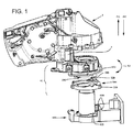
本明細書で説明されている例で指定された折り畳み式リアビューミラーアセンブリは、図示しないミラー板を受け入れるのに適したミラーハウジング1を備える。モータハウジング2は、ミラーハウジング1に取り付けられているか、又はその一部であり、ここに図示されていない電動機を内部に収容するように適合されている。電動機には以下に説明する駆動ギヤ120が接続され、自動車の車体に取り付けられた固定部400に形成された上向きに延びるステムに対して、第1部材100、したがってミラーハウジング1を回転させる。
The foldable rear view mirror assembly specified in the example described herein comprises a
図示された例における折り畳み式リアビューミラーアセンブリは、図1及び図2に完全に示されているアクチュエータ機構10をさらに備える。アクチュエータ機構10は、リアビューミラーハウジング1を、適切な角度位置、具体的には、駆動位置、例えば、リアビューミラーに外力や衝撃が加わった場合、リアビューミラーを手動で動作した場合、電源が供給できない場合等で、リアビューミラーハウジング1を手動で適切に位置決めすることを可能にすることを意図している。
The foldable rear view mirror assembly in the illustrated example further comprises an
アクチュエータ機構10は、固定部400に対して相対移動可能になるように、リアビューミラーハウジング1に取り付けられた第1部材100を備えている。図示されているように、第1部材100は、下方に延びる第1係止部110を有し、その目的は以下に記述される。
The
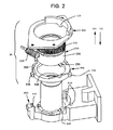
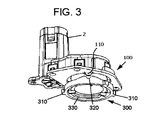
本折り畳み式のリアビューミラーアセンブリ1のアクチュエータ機構10は、第3部材300をさらに備える。第3部材300は、第1係止部310を備え、図示の例では、第1係止部310は、対応する第1係止部410に受け入れられるように半径方向外側に延びる突起を備え、図示の例では、第1係止部410は、自動車の前記固定部400に半径方向に形成された凹部を備える。第3部材300の半径方向突起310が固定部400の対応する半径方向凹部410内に挿入されると、第3部材300は常に回転しないように係止されたままである。
The
アクチュエータ機構10は、上述したように、固定部400の上述のステムと同心に配置された第2部材200をさらに備える。また、図示するように、第3部材300は、第2部材200と同心に配置されている。
As described above, the
第2部材200と第1部材100との両方は、固定部400の上記上方に延びるステムの周りを回転することができる。第3部材300は、固定部400のステムに対して同心に配置される。
Both the
第2部材200は、第1駆動部210及び第2駆動部220を有する。
The
第1駆動部210は、モータハウジング2に嵌合された図示しない電動機によって順番に駆動される駆動ギヤ120に係合する歯付リングである。
The
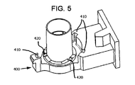
第2部材200の第2駆動部220は、第1駆動及び第2駆動要素を有し、この例では、第2部材200の第2駆動部220から半径方向下方に突出する半径方向下方の突起230が、2つの異なる機能を実行するように示されている。第2部材の第2駆動部220は係止要素も有し、図示された例では、半径方向下方の突起230に一体化されている。半径方向下方の突起230は、平坦な上面と、2つの傾斜面が形成された下方に突出するくさび形の下部と、を有するように構成される。第2部材200が第3部材300に形成された傾斜した内側ガイド又は面330上を摺動する固定部400に対して回転すると、半径方向下方突起230の平坦な上面は、第3部材300を第1部材100に向かう方向D1に移動させる目的で駆動要素として機能する。一方、半径下方向突起230の下方に突出するくさび形の下部は、第2部材200を固定部400の係止部420に係止するための係止手段として作用する。したがって、半径方向下方突起230は、上述のように二重の目的を有するが、両方の機能は、別個の又は一体の部品によって実施することができる。
The
第2部材200は、第1部材100に取り付けられ、その結果、ミラーハウジング1が電動機によって作動されるため、加えられるトルクは、第2部材200の半径方向下方の突起230を固定部400に対して係止解除するのに十分な大きさではない。その結果、第1部材100は、第1駆動部210を中心に回転する。一方、ミラーハウジング1がユーザにより手動作動されると、第1部材100と第2部材200との間には相対的な動きが存在しない。これにより、第1部材100と第2部材200は、共に固定部400に対して回転する。第1部材100と第2部材200の回転により、第3部材300が上方に変位し、第1部材100を所定位置に係止することができ、第3部材300を回転させることができないので、第1部材100と第3部材300の両方の回転が係止される。
Since the
3つの異なるトルク値を以下のように定義する。第1トルクT1は、第1部材100がミラーハウジング1を作動させるために電動機によって駆動されるときに加えられるトルクに対応する。第1トルクT1が電動機によって加えられると、第2部材200が固定部400に固定された状態で、第1部材100が第2部材200の第1駆動部210を中心に回転する。第2トルクT2は、第1部材100がユーザによって手動で駆動されるときに加えられるトルクに対応する。この場合、第1部材100は第2部材200に対して回転しない、すなわち第1部材100と第2部材200とが一緒に回転するのは、第1部材が電動機によって駆動されないので、第1駆動部210と駆動ギヤ120との間に機械的なブロックが存在するためである。最大所定トルクTmaxは、ミラーハウジング1を手動で駆動する際に、第2部材200を固定部400から係止解除するために加えられるトルクに対応する。
Three different torque values are defined as follows: The first torque T1 corresponds to the torque applied when the
したがって、上記の異なるトルク値によれば、以下の式が満たされる。
T1<Tmax<T2
Therefore, according to the different torque values, the following equation is satisfied.
T1 <Tmax <T2
これにより、第1部材100は、最大所定トルクTmaxを超えないトルクである第1トルクT1が電動機により加えられて回転するので、第2部材200は固定部400に回転が係止されたままである。
As a result, the
一方、第2部材200と固定部400とが連動される場合、第3部材300に形成された内側ガイドに作成された対応する凹部331には、半径方向下方突起230が位置する。第1部材100が最大所定トルクTmaxを超える第2トルクT2を加えるユーザによって手動で回転されると、半径方向下方の突起230は、第1部材100に向かって方向D1に沿って第3部材300を上方に移動させ、半径方向下方突起230により、固定部400の係止部420及び第3部材300に形成された内側ガイドの対応する凹部331を、内側ガイド330に形成された平坦領域332に残し、第3部材300を第1部材100に向かってD1方向に沿って上方に移動させる。第1部材100の回転は、第1部材100の係止部110を第3部材300の上に移動させ、凹部320に到達させ、両部材300,100が連動される。
On the other hand, when the
アクチュエータ機構10が前の位置にあるとき、第1部材100と第3部材300とが連動された状態で、電気的作動又は別の手動あるいは外部トルクの2つの動作をとることができる。
When the
電動機が作動すると、第1部材100が第3部材300に係止されているので、第2部材200は、固定部400の上記ステムに対して、半径方向下方突起230が係止部420に再度嵌り込むまで回転し、順番に、半径方向下方突起230の上面は、第3部材300に形成された内側ガイド330の凹部331に入る。その結果、第3部材300は、重力によりD2方向に固定部400に向かって移動して元の位置に戻る。一方、第2部材200が固定部400に再び係止され、第3部材300が第1部材100に対して係止解除されると、第1部材100は、最終位置に達するまで、第2部材200を中心に回転を開始する。
When the electric motor is activated, the
一方、それは第2部材200の移動開始時に起こり得て、第3部材300は、半径方向下方突起230が固定部400の係止部420に係止される前に、方向D2に沿って下方に移動され、その結果、第3部材300が第1部材100から係止解除される。このように、例えば、走行停止の端部のような機械的ブロックによって停止されるまで、第2部材200が停止し、第1部材100が回転する。次いで、第2部材200は、電動機が停止すると、半径方向下方突起230が固定部400の係止部420に係止されるまで回転する。
On the other hand, this may occur at the start of movement of the
上記の何れの場合も、ミラーハウジング1をその通常の動作に戻して、これを電動機によって手動で再び駆動することができるようになるリセット機能が設けられている。
In any of the above cases, a reset function is provided that allows the
リアビューミラーが手動力又は衝撃によって外部から作動される場合、トルクは最終的に第1係止部110と第2係止部320との間の係止を克服するのに十分なものとなる。固定部400の半径方向下方突起230及び係止部420が再び別の位置に係合されるまで、前記第1及び第2係止部110,320の係合が外れ、第2部材200と共に第1部材100が第3部材300及び固定部400に対して相対的に回転する。
If the rearview mirror is actuated externally by manual force or impact, the torque will eventually be sufficient to overcome the locking between the
第3部材300は、第2部材200の上記の半径方向の突起230を受け入れるように適合されている内側ガイド330を有しここで摺動する。第3部材300の内側ガイド330は、傾斜面と対応する凹部331及び平坦領域332を備え、第1部材100が自動車の固定部400に対して第2部材200と共に回転するときに、第3部材300が第1部材100に向かって及び離れる前記方向D1、D2に沿って移動するのを助ける。
The
自動車用の折り畳み式のリアビューミラーアセンブリの手動操作のための本アクチュエータ機構の多くの特定の実施形態及び例のみが本明細書に開示されているが、当業者には、他の代替例及び/又は使用ならびに明確な修正やそれらの均等物が可能であることを理解されたい。本開示は、記載される特定の例の可能な全ての組み合わせを包含する。 Although only a number of specific embodiments and examples of the present actuator mechanism for manual operation of a folding rear view mirror assembly for an automobile are disclosed herein, those skilled in the art will recognize other alternatives and / or Or it should be understood that use and obvious modifications and equivalents thereof are possible. This disclosure includes all possible combinations of the specific examples described.
異なる部品を示すための「第1」、「第2」などの用語の使用は、いかなる順序も含まず、必ずしも他のさらなる部品を排除するものではない。特許請求の範囲の括弧内の図面に関連する参照符号は、単に、特許請求の範囲の明瞭性を高めるためのものであり、請求の範囲を限定するものと解釈されるべきではない。 The use of terms such as “first”, “second”, etc. to indicate different parts does not include any order and does not necessarily exclude other additional parts. Reference signs associated with the drawings in the parentheses in the claims are merely for the purpose of enhancing the clarity of the claims and should not be construed as limiting the claims.
本開示の範囲は、特定の例によって限定されるべきではなく、以下の特許請求の範囲を公正に読むことによってのみ決定されるべきである。 The scope of the present disclosure should not be limited by the specific examples, but should be determined only by fair reading of the following claims.
Claims (13)
旋回可能なリアビューミラーハウジング(1)に関連し、それと共に移動可能な第1部材(100)と、
前記第1部材(100)に向かう方向(D1)及び前記第1部材(100)から離れる方向(D2)に移動するように構成された第3部材(300)と、
第2部材(200)と、
を備え、
前記第2部材(200)は、前記第1部材(100)が最大所定トルク(Tmax)を超えない第1トルク(T1)だけ回転されるときに、動力で動く乗り物の固定部(400)に回転が係止されるように適合され、
前記第2部材(200)は、前記最大所定トルク(Tmax)を超える第2トルク(T2)で前記第1部材(100)が回転するときに、前記第3部材(300)を前記第1部材(100)に向かう前記方向(D1)に移動するようにさらに適合され、これにより、前記第1部材及び前記第3部材を前記第1部材(100)の所定位置に連動させる、
アクチュエータ機構(10)。 An actuator mechanism (10) for a foldable rear view mirror assembly for a powered vehicle, the actuator mechanism (10) comprising:
A first member (100) associated with and movable with the pivotable rear view mirror housing (1);
A third member (300) configured to move in a direction (D1) toward the first member (100) and a direction (D2) away from the first member (100);
A second member (200);
With
When the first member (100) is rotated by a first torque (T1) that does not exceed a maximum predetermined torque (Tmax), the second member (200) is a fixed part (400) for a vehicle that moves by power. Adapted to lock the rotation,
The second member (200) moves the third member (300) to the first member when the first member (100) rotates with a second torque (T2) exceeding the maximum predetermined torque (Tmax). Further adapted to move in the direction (D1) toward (100), thereby interlocking the first member and the third member with a predetermined position of the first member (100);
Actuator mechanism (10).
請求項1に記載のアクチュエータ機構(10)。 The second member (200) has a first driving part (210) adapted to be driven by driving means for rotating the first member (100) and the first part (210) with respect to the fixing part (400). When the one member (100) rotates, the second driving unit (220) having a plurality of driving elements for driving the third member (300) in the direction (D1) toward the first member (100). Prepare
The actuator mechanism (10) according to claim 1.
請求項1又は2に記載のアクチュエータ機構(10)。 The second member (200) is arranged to rotate with the first member (100).
Actuator mechanism (10) according to claim 1 or 2.
請求項2又は3に記載のアクチュエータ機構(10)。 The second member (200) is configured to move the third member in the direction (D1) toward the first member (100) when the first member (100) rotates with respect to the fixing portion (400). A first drive element (230) suitable for driving (300),
Actuator mechanism (10) according to claim 2 or 3.
請求項1乃至4の何れかに1項に記載のアクチュエータ機構(10)。 In a state where the first member (100) is rotated with respect to the second member (200) with the first torque (T1) not exceeding the maximum predetermined torque (Tmax), the second member (200) is Adapted to be locked to the fixing part (400),
Actuator mechanism (10) according to any one of the preceding claims.
前記内側ガイド(330)は、前記第2部材(200)が前記第1部材(100)に向かう方向(D1)及び前記第1部材(100)から離れる方向(D2)に前記第3部材(300)を移動させるのを助ける傾斜面を有する、
請求項2〜5の何れか1項に記載のアクチュエータ機構(10)。 The third member (300) includes an inner guide (330) on which a driving element of the second driving unit (220) can slide.
The inner guide (330) includes the third member (300) in a direction (D1) in which the second member (200) faces the first member (100) and in a direction (D2) away from the first member (100). Have an inclined surface to help move)
The actuator mechanism (10) according to any one of claims 2 to 5.
前記外部ガイドは、前記第3部材(300)を前記第1部材(100)に向かう方向(D1)及び前記第1部材(100)から離れる方向(D2)に移動させるための傾斜面を有する、
請求項1乃至6の何れか1項に記載のアクチュエータ機構(10)。 The second driving part (220) of the second member (200) has an external guide on which the second locking part (230) of the third member (300) can slide.
The external guide has an inclined surface for moving the third member (300) in a direction (D1) toward the first member (100) and in a direction (D2) away from the first member (100).
The actuator mechanism (10) according to any one of the preceding claims.
請求項1乃至7の何れか1項に記載のアクチュエータ機構(10)。 The third member (300) is a first locking portion (310) adapted to engage with a corresponding first locking portion (410) formed in the fixed portion (400) of a vehicle that is powered by power. ), Thereby locking the rotation of the third member (300).
Actuator mechanism (10) according to any one of the preceding claims.
請求項8に記載のアクチュエータ機構(10)。 The first locking portion comprises a locking protrusion (310) adapted to be received in a corresponding locking recess (410) formed in the fixed portion (400) of the powered vehicle. To lock the rotation of the third member (300),
Actuator mechanism (10) according to claim 8.
請求項4〜8の何れか1項に記載のアクチュエータ機構(10)。 The first member (100) has a number of protrusions (110) adapted to be locked in correspondence with the second locking portion (320) of the third member (300).
The actuator mechanism (10) according to any one of claims 4 to 8.
第2係止部(320)は、前記突起(110)を受け入れるように適合された凹部を備える、
請求項10に記載のアクチュエータ機構(10)。 The first locking portion includes a protrusion (110),
The second locking portion (320) comprises a recess adapted to receive the protrusion (110).
Actuator mechanism (10) according to claim 10.
請求項1〜11の何れか1項に記載のアクチュエータ機構(10)。 The predetermined position at which the first member (100) and the third member (300) are interlocked corresponds to the position of the rear view mirror housing (1) for driving a vehicle that moves by power.
The actuator mechanism (10) according to any one of claims 1 to 11.
請求項1乃至12の何れか1項の前記アクチュエータ機構(10)と、
動力で動く乗り物に取り付けられた前記固定部(400)に対して回転するように適合された前記リアビューミラーハウジング(1)と、
を備える、
折り畳み式リアビューミラーアセンブリ(M)。 A foldable rear view mirror assembly (M) for a powered vehicle, the foldable rear view mirror assembly (M) comprising:
The actuator mechanism (10) according to any one of claims 1 to 12,
The rear view mirror housing (1) adapted to rotate relative to the fixed part (400) attached to a powered vehicle;
Comprising
Foldable rear view mirror assembly (M).
Applications Claiming Priority (2)
| Application Number | Priority Date | Filing Date | Title |
|---|---|---|---|
| EP17382348.5A EP3412509B1 (en) | 2017-06-07 | 2017-06-07 | Actuator mechanism for a fold rear-view mirror assembly |
| EP17382348.5 | 2017-06-07 |
Publications (2)
| Publication Number | Publication Date |
|---|---|
| JP2018203251A true JP2018203251A (en) | 2018-12-27 |
| JP2018203251A5 JP2018203251A5 (en) | 2021-07-26 |
Family
ID=59078004
Family Applications (1)
| Application Number | Title | Priority Date | Filing Date |
|---|---|---|---|
| JP2018109136A Pending JP2018203251A (en) | 2017-06-07 | 2018-06-07 | Folding type rear view mirror assembly actuator mechanism |
Country Status (4)
| Country | Link |
|---|---|
| US (1) | US10703280B2 (en) |
| EP (1) | EP3412509B1 (en) |
| JP (1) | JP2018203251A (en) |
| CN (1) | CN108995595B (en) |
Citations (8)
| Publication number | Priority date | Publication date | Assignee | Title |
|---|---|---|---|---|
| JP2000503938A (en) * | 1996-05-15 | 2000-04-04 | イク ホールディング モントフォールト ビー.ヴイ. | Electric pivot actuator and rearview mirror having electric pivot mechanism |
| DE10300942B3 (en) * | 2003-01-13 | 2004-07-22 | Em Kunststofftechnik Gmbh | Mechanical setting device for holder for automobile external rear view mirror with ratchet device for locking mirror holder in required position |
| WO2005075249A1 (en) * | 2004-02-06 | 2005-08-18 | Eaton Automotive B.V. | Hinge actuator and method for adjusting two parts of a hinge actuator relative to each other |
| DE202012003399U1 (en) * | 2012-02-16 | 2012-04-19 | Mci (Mirror Controls International) Netherlands B.V. | Exterior mirror and hinge actuator for such |
| CN204488646U (en) * | 2015-03-12 | 2015-07-22 | 宁波世叠汽车科技发展有限公司 | A kind of automobile rearview mirror electrically-driven device |
| CN204821345U (en) * | 2015-08-22 | 2015-12-02 | 宁波精成车业有限公司 | A electronic folding device for vapour exterior mirror |
| WO2017031953A1 (en) * | 2015-08-22 | 2017-03-02 | 宁波精成车业有限公司 | Electric folding device for outside rear-view mirror of vehicle |
| WO2017074193A1 (en) * | 2015-10-28 | 2017-05-04 | Mci (Mirror Controls International) Netherlands B.V. | Ajustment instrument for an exterior vision unit for a vehicle |
Family Cites Families (12)
| Publication number | Priority date | Publication date | Assignee | Title |
|---|---|---|---|---|
| NL1018689C2 (en) * | 2001-08-02 | 2003-02-04 | Iku Holding Montfoort Bv | Housing for a mirror actuator. |
| US4832477A (en) * | 1986-09-30 | 1989-05-23 | Aisin Seiki Kabushiki Kaisha | Door mirror assembly for automotive vehicles |
| NL1025437C2 (en) | 2004-02-06 | 2005-08-09 | Iku Holding Montfoort Bv | Hinge actuator. |
| JP4847311B2 (en) * | 2006-12-25 | 2011-12-28 | 株式会社東海理化電機製作所 | Mirror device for vehicle |
| NL2006301C2 (en) | 2010-10-06 | 2012-04-11 | Mci Mirror Controls Int Nl Bv | ADJUSTMENT MECHANISM. |
| EP2439106B1 (en) * | 2010-10-08 | 2012-12-05 | SMR Patents S.à.r.l. | Power fold mechanism |
| EP2639110A1 (en) * | 2012-03-14 | 2013-09-18 | Magna Auteca AG | Drive assembly for an external rear mirror in a vehicle |
| EP2639112B1 (en) * | 2012-03-14 | 2014-10-01 | Magna Auteca AG | Group of external mirrors with different functions |
| JP6019664B2 (en) * | 2012-03-28 | 2016-11-02 | 市光工業株式会社 | Outside mirror device for vehicle |
| US9758100B2 (en) * | 2013-05-23 | 2017-09-12 | Fico Mirrors, S.A. | Folding rearview mirror for motor vehicles |
| EP3142900B1 (en) * | 2014-05-14 | 2018-07-11 | Fico Mirrors S.A. | Fold rearview mirror assembly for motor vehicles |
| CN104691420B (en) * | 2015-03-13 | 2017-01-11 | 宁波精成车业有限公司 | Adjusting device used for automobile rearview mirror |
-
2017
- 2017-06-07 EP EP17382348.5A patent/EP3412509B1/en active Active
-
2018
- 2018-06-07 CN CN201810647304.5A patent/CN108995595B/en active Active
- 2018-06-07 JP JP2018109136A patent/JP2018203251A/en active Pending
- 2018-06-07 US US16/002,663 patent/US10703280B2/en active Active
Patent Citations (9)
| Publication number | Priority date | Publication date | Assignee | Title |
|---|---|---|---|---|
| JP2000503938A (en) * | 1996-05-15 | 2000-04-04 | イク ホールディング モントフォールト ビー.ヴイ. | Electric pivot actuator and rearview mirror having electric pivot mechanism |
| DE10300942B3 (en) * | 2003-01-13 | 2004-07-22 | Em Kunststofftechnik Gmbh | Mechanical setting device for holder for automobile external rear view mirror with ratchet device for locking mirror holder in required position |
| WO2005075249A1 (en) * | 2004-02-06 | 2005-08-18 | Eaton Automotive B.V. | Hinge actuator and method for adjusting two parts of a hinge actuator relative to each other |
| US20070029179A1 (en) * | 2004-02-06 | 2007-02-08 | Eaton Automotive B.V. | Hinge actuator and method for adjusting two parts of a hinge actuator relative to each other |
| DE202012003399U1 (en) * | 2012-02-16 | 2012-04-19 | Mci (Mirror Controls International) Netherlands B.V. | Exterior mirror and hinge actuator for such |
| CN204488646U (en) * | 2015-03-12 | 2015-07-22 | 宁波世叠汽车科技发展有限公司 | A kind of automobile rearview mirror electrically-driven device |
| CN204821345U (en) * | 2015-08-22 | 2015-12-02 | 宁波精成车业有限公司 | A electronic folding device for vapour exterior mirror |
| WO2017031953A1 (en) * | 2015-08-22 | 2017-03-02 | 宁波精成车业有限公司 | Electric folding device for outside rear-view mirror of vehicle |
| WO2017074193A1 (en) * | 2015-10-28 | 2017-05-04 | Mci (Mirror Controls International) Netherlands B.V. | Ajustment instrument for an exterior vision unit for a vehicle |
Also Published As
| Publication number | Publication date |
|---|---|
| CN108995595B (en) | 2023-06-06 |
| EP3412509A1 (en) | 2018-12-12 |
| CN108995595A (en) | 2018-12-14 |
| US20180354421A1 (en) | 2018-12-13 |
| US10703280B2 (en) | 2020-07-07 |
| EP3412509B1 (en) | 2020-01-08 |
Similar Documents
| Publication | Publication Date | Title |
|---|---|---|
| US7572018B2 (en) | Folding mechanism for exterior rear-view mirrors of automotive vehicles | |
| US8366284B2 (en) | Vehicle mirror power fold mechanism | |
| JP4845911B2 (en) | Hinge mechanism and vehicle seat having the mechanism | |
| JP3151529B2 (en) | Rearview mirror having electric pivot actuator and electric pivot mechanism | |
| US9108540B2 (en) | Power fold with lock for vehicle seat | |
| JP6124792B2 (en) | Adjustment mechanism | |
| JP5075812B2 (en) | Vehicle seat and its disc recliner | |
| CN112389331B (en) | Combined actuator for turning and lifting rearview mirror, rearview device and vehicle | |
| KR101230219B1 (en) | Hinge actuator and method for adjusting two parts of a hinge actuator relative to each other | |
| CN106458099B (en) | The collapsible rearview mirror assemblies of motor vehicles | |
| EP3022832A1 (en) | Driving device of electric folding type side view mirror for a vehicle | |
| JP2018199356A (en) | Lifter device | |
| WO2009035931A1 (en) | Universal folding bracket assembly for either manual fold or power fold rearview mirrors | |
| JP2018203251A (en) | Folding type rear view mirror assembly actuator mechanism | |
| CA2061492A1 (en) | Adjustable seat recliner apparatus and method of making same | |
| JP2019163031A (en) | Connector device for rear view mirror of power driven vehicle | |
| JP2002200940A (en) | Rear-view mirror for automobile | |
| KR100477556B1 (en) | A folding unit of side mirror for mobile | |
| TWI775222B (en) | Child seat limit rotation lock and safety seat with child seat limit rotation lock | |
| JPH0512112Y2 (en) | ||
| JP4534068B2 (en) | Reclining seat for automobile with shoulder belt | |
| KR101073456B1 (en) | Apparatus for reclining seat of automobile | |
| JP2018203251A5 (en) |
Legal Events
| Date | Code | Title | Description |
|---|---|---|---|
| A521 | Request for written amendment filed |
Free format text: JAPANESE INTERMEDIATE CODE: A523 Effective date: 20210604 |
|
| A621 | Written request for application examination |
Free format text: JAPANESE INTERMEDIATE CODE: A621 Effective date: 20210604 |
|
| A871 | Explanation of circumstances concerning accelerated examination |
Free format text: JAPANESE INTERMEDIATE CODE: A871 Effective date: 20210604 |
|
| A131 | Notification of reasons for refusal |
Free format text: JAPANESE INTERMEDIATE CODE: A131 Effective date: 20210831 |
|
| A02 | Decision of refusal |
Free format text: JAPANESE INTERMEDIATE CODE: A02 Effective date: 20220322 |