JP2018187699A - Electric tool - Google Patents
Electric tool Download PDFInfo
- Publication number
- JP2018187699A JP2018187699A JP2017090265A JP2017090265A JP2018187699A JP 2018187699 A JP2018187699 A JP 2018187699A JP 2017090265 A JP2017090265 A JP 2017090265A JP 2017090265 A JP2017090265 A JP 2017090265A JP 2018187699 A JP2018187699 A JP 2018187699A
- Authority
- JP
- Japan
- Prior art keywords
- battery pack
- housing
- motor
- fan
- window
- Prior art date
- Legal status (The legal status is an assumption and is not a legal conclusion. Google has not performed a legal analysis and makes no representation as to the accuracy of the status listed.)
- Pending
Links
Images


Classifications
-
- B—PERFORMING OPERATIONS; TRANSPORTING
- B25—HAND TOOLS; PORTABLE POWER-DRIVEN TOOLS; MANIPULATORS
- B25F—COMBINATION OR MULTI-PURPOSE TOOLS NOT OTHERWISE PROVIDED FOR; DETAILS OR COMPONENTS OF PORTABLE POWER-DRIVEN TOOLS NOT PARTICULARLY RELATED TO THE OPERATIONS PERFORMED AND NOT OTHERWISE PROVIDED FOR
- B25F5/00—Details or components of portable power-driven tools not particularly related to the operations performed and not otherwise provided for
- B25F5/008—Cooling means
Landscapes
- Engineering & Computer Science (AREA)
- Mechanical Engineering (AREA)
- Portable Power Tools In General (AREA)
Abstract
Description
本発明は、電動工具本体に電池パックを着脱自在に装着可能な構成を有する電動工具に関する。 The present invention relates to a power tool having a configuration in which a battery pack can be detachably attached to a power tool body.
一般に、電動モータを内蔵した電動工具本体に対して電池パックを着脱自在とし、作業時に電池パックを装着して使用する電動工具が知られている。電池パックに内蔵される電池セルは自身の持つ内部抵抗により発熱するため、高負荷になると電池セルの温度が大きく上昇する。 2. Description of the Related Art Generally, an electric tool is known in which a battery pack is detachable from an electric tool main body incorporating an electric motor, and the battery pack is attached during use. Since the battery cell built in the battery pack generates heat due to its internal resistance, the temperature of the battery cell greatly increases when the load is high.
電池セルの温度が所定の閾値を超えると、電池セルを保護するために、電池セルの温度が下がるまで電池パックからの電力供給を停止する必要がある。作業効率化の観点では、こうした保護機能の作動は少ないことが好ましい。 When the temperature of the battery cell exceeds a predetermined threshold, it is necessary to stop the power supply from the battery pack until the temperature of the battery cell decreases in order to protect the battery cell. From the viewpoint of improving work efficiency, it is preferable that the operation of such a protection function is small.
本発明はこうした状況を認識してなされたものであり、その目的は、電池パックの冷却性能に優れた電動工具を提供することにある。 The present invention has been made in view of such a situation, and an object thereof is to provide an electric tool having excellent battery pack cooling performance.
本発明のある態様は電動工具である。この電動工具は、
モータと、
前記モータを収容するハウジングと、
前記モータによって回転するファンと、
前記ハウジングのモータ収容部の側方に配置されて、前記モータに電力を供給する電池パックと、
前記ハウジングに設けられる第1の風窓と、
前記電池パックを冷却するための第2の風窓と、を備え、
前記ファンの回転によって、前記第1の風窓と前記ファンとを結ぶ第1の冷却風路と、前記第2の風窓と前記ファンとを結ぶ第2の冷却風路とが形成されることを特徴とする。
One embodiment of the present invention is a power tool. This electric tool
A motor,
A housing for housing the motor;
A fan rotated by the motor;
A battery pack disposed on the side of the motor housing portion of the housing and supplying power to the motor;
A first wind window provided in the housing;
A second wind window for cooling the battery pack,
A rotation of the fan forms a first cooling air passage connecting the first air window and the fan, and a second cooling air passage connecting the second air window and the fan. And
前記第2の風窓は前記電池パックに設けられてもよい。 The second wind window may be provided in the battery pack.
前記第2の風窓は前記ハウジングに設けられる排気口であってもよい。 The second air window may be an exhaust port provided in the housing.
前記第2の冷却風路においては、前記電池パック内から前記ファンに向けて冷却風が流れてもよい。 In the second cooling air passage, cooling air may flow from the battery pack toward the fan.
前記第2の冷却風路においては、前記ファンから前記電池パックに向けて冷却風が流れてもよい。 In the second cooling air passage, cooling air may flow from the fan toward the battery pack.
なお、以上の構成要素の任意の組合せ、本発明の表現を方法やシステムなどの間で変換したものもまた、本発明の態様として有効である。 It should be noted that any combination of the above-described constituent elements, and those obtained by converting the expression of the present invention between methods and systems are also effective as aspects of the present invention.
本発明に係る電動工具によれば、電池パックの冷却性能に優れた電動工具を提供することができる。 According to the electric tool of the present invention, it is possible to provide an electric tool that is excellent in the cooling performance of the battery pack.
以下、図面を参照しながら本発明の好適な実施の形態を詳述する。なお、各図面に示される同一または同等の構成要素、部材等には同一の符号を付し、適宜重複した説明は省略する。また、実施の形態は発明を限定するものではなく例示であり、実施の形態に記述されるすべての特徴やその組み合わせは必ずしも発明の本質的なものであるとは限らない。 Hereinafter, preferred embodiments of the present invention will be described in detail with reference to the drawings. In addition, the same code | symbol is attached | subjected to the same or equivalent component, member, etc. which are shown by each drawing, and the overlapping description is abbreviate | omitted suitably. In addition, the embodiments do not limit the invention but are exemplifications, and all features and combinations thereof described in the embodiments are not necessarily essential to the invention.
実施の形態1
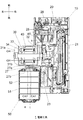
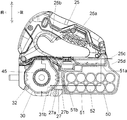
図1は、本発明の実施の形態1に係る電動工具1の平断面図である。図2は、図1のII−II断面図である。図1及び図2により、電動工具1の前後、上下、左右の各方向を定義する。図3は、電動工具1に着脱可能に装着される電池パック50の斜視図である。電池パック50は、本体ハウジング20に対して前後方向にスライドするようにして着脱される。電動工具1は、コードレスタイプの携帯用切断機(携帯丸鋸)であり、着脱可能に装着した電池パック50からの供給電力で動作する。電動工具1は、ベース10と、ベース10に取り付けられた本体ハウジング20と、を備える。ベース10は、例えばアルミ等の金属製の略長方形の板材である。ベース10の長手方向は、切断方向と一致する。ベース10の底面は、被削材との摺動面である。本体ハウジング20は、ベース10に前後2箇所で連結され、ベース10に対して上下方向に回動可能かつ左右少なくとも一方に傾動可能である。
Embodiment 1
FIG. 1 is a plan sectional view of a power tool 1 according to Embodiment 1 of the present invention. 2 is a cross-sectional view taken along the line II-II in FIG. 1 and 2, the front / rear, top / bottom and left / right directions of the power tool 1 are defined. FIG. 3 is a perspective view of the
本体ハウジング20は、ハンドルハウジング25と、ギヤカバー28と、モータハウジング(モータ収容部)30と、を含む。モータハウジング30は、例えば樹脂成形体であり、モータ(ブラシレスモータ)40及びインバータ回路基板33を収容する。インバータ回路基板33は、モータ40の左方に位置し、FETやIGBT等のスイッチング素子34を複数搭載する。ハンドルハウジング25は、例えば樹脂成形体であり、図2に示すようにグリップ部25aを有する。グリップ部25aには、使用者がモータ40の駆動、停止を切り替えるためのトリガスイッチ25bが設けられる。
The
ハンドルハウジング25には、モータハウジング30の側方(後方)となる位置に、電池パック50が後方から前方に向かって(モータハウジング30に近づくように)スライド装着される。ここで、モータハウジング30の側方とは、モータ40の径方向(出力軸と垂直な方向)においてモータハウジング30の外側であることを意味する。モータハウジング30と電池パック50は、互いに隣り合う(近傍に位置する)。ハンドルハウジング25は、装着した電池パック50の右方となる位置に、制御回路基板23を収容する。制御回路基板23は、スイッチング素子34のオンオフ制御(例えばPWM制御)によりモータ40の駆動を制御するコントローラを搭載する。トリガスイッチ25bがオンになると、コントローラの制御によりモータ40が駆動される。モータ40の回転は、減速機構によって減速されて丸鋸刃21に伝達される。
The
以下、電動工具1における冷却構造を説明する。モータ40の右方には、ファン45が同軸に設けられる。ファン45は、遠心ファンである。ファン45の外周部のモータ40側は、モータハウジング30のファンガイド部32と対面する。モータハウジング30は、風窓31a、31bを有する。第1の風窓としての風窓31aは、吸気口であって、モータ40の左方に設けられる。風窓31bは、排気口であって、ファンガイド部32の左側においてモータ40の右端部と対向する位置であって電池パック50に臨む位置に設けられる。
Hereinafter, the cooling structure in the electric power tool 1 will be described. A
モータハウジング30と電池パック50との間には、ハンドルハウジング25の風路ガイド部27が延在する。風路ガイド部27は、風窓27a、27bを有する。風窓27aは、モータハウジング30の風窓31bと近接し風窓31bと連通する。風窓27bは、電池パック50の風窓51bと近接し風窓51bと連通する。風路ガイド部27は、コスト・組立性の観点からハンドルハウジング25と一体に形成したが、例えばゴム等の弾性体からなる独立した部品として形成し、電池パック50と圧接するように構成することで冷却風の外部漏れを抑制するようにしてもよい。
An air path guide
電池パック50は、電池ハウジング51の内部に複数の電池セル52を収容したものであり、電池ハウジング51には風窓51a、51bが設けられる。具体的には、10個の電池セル52が、長手方向を左右方向に沿わせるようにして前後に5個並べたものを上下に重ねるようにして電池パック50内に設けられる。風窓51a、51bは、電池パック50を不図示の充電器に接続して充電する際に前記充電器のファンが発生する気流を電池ハウジング51内に通すために従来から存在していたものである。風窓51aは、第2の風窓であって吸気口として機能し、電池ハウジング51の後部上面に設けられる。風窓51bは、排気口として機能し、電池ハウジング51の前面に設けられる。電池セル52が占める空間は前後方向に長く、風窓51aと風窓51bを電池パック50の前後に設けることで、風窓51aと風窓51bとを結ぶ冷却風路上に大部分の電池セル52を含めることができ、少ない風窓数でも効果的に電池セル52を冷却することができる。
The
ハンドルハウジング25は、風窓25c、25dを有する。風窓25cは、ハンドルハウジング25の後端部に設けられる。風窓25dは、電池パック50の風窓51aと近接し風窓51aと連通する。
The
ファン45の回転によって、第1の冷却風路としての風路CA1と、第2の冷却風路としての風路CA2と、が形成される。風路CA1は、風窓31aからモータハウジング30の内部に入り、モータ40の内部ないし近傍を通ってモータ40を冷却し、ファンガイド部32の内側を通過してファン45に至る。風路CA2は、風窓25c、25d、51aを通って電池ハウジング51の内部に入り、電池セル52の近傍を通って電池セル52を冷却し、風窓51bを通って電池ハウジング51の外部に排出され、風窓27b、27a、31bを通ってモータハウジング30の内部に入り、風路CA1と合流してファンガイド部32の内側を通ってファン45に至る。
By the rotation of the
本実施の形態によれば、主に下記の効果を奏することができる。 According to the present embodiment, the following effects can be mainly achieved.
(1) モータ冷却用のファン45を利用して電池パック50の冷却も行うため、部品点数を抑制しながら電池パック50を冷却でき、電池パック50の保護機能が作動することによる作業効率の悪化を抑制できる。
(1) Since the
(2) 電池パック50内に取り込まれる冷却風は、モータ40等の他の部品を冷却していない新鮮な冷却風であるため、電池パック50の冷却効率が高い。
(2) Since the cooling air taken into the
(3) 電池パック50の上向きの風窓51aは、本体ハウジング20を通して(風窓25c、25dを通して)空気を取り込むため、電池パック50側の上向き風窓51aは外気に露出せず、電池パック50内に粉塵が流入しにくい。
(3) Since the
(4) 電池パック50の風窓51a、51bは、充電時用に従来から存在するものであるため、ファン45による電池パック50の冷却のために電池ハウジング51の形状を変える必要が無い。また、電池パック50をモータハウジング20に隣接させて(前後方向に並ぶように)配置したので、電池パック50に設けた風窓とモータハウジング20内に形成される冷却風路とを連通させやすい。
(4) Since the
(5) 前後に並んだ電池セル52を効果的に冷却するために前後に風窓を設けた電池パック50を本体ハウジング20に対して前後方向にスライドさせて装着するようにしたので、前部に設けた電池パック50の風窓51bをモータハウジング30内に流れる冷却風及びファン45の近傍に位置させることができ、ファン45と風窓51bを結ぶ冷却風路を短くすることができるので、風路形成のための空間を少なくすることができ、本体ハウジング20を小型化できる。
(5) In order to effectively cool the
実施の形態2
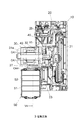
図4は、本発明の実施の形態2に係る電動工具2の平断面図である。図5は、図4のV−V断面図である。本実施の形態の電動工具2は、実施の形態1のものと比較して、風窓31bが無くなり、風路CA2が風路CA3に替わっている。本実施の形態では、電池パック50の風窓51bは吸気口として機能し、風窓51aは排気口として機能する。風路CA3は、ファン45から風路ガイド部27内を通り、風窓27b、51bを通って電池ハウジング51の内部に入り、電池セル52の近傍を通って電池セル52を冷却し、風窓51aを通って電池ハウジング51の外部に排出され、風窓25d、25cを通ってハンドルハウジング25の外部に排出される。本実施の形態のその他の点は、実施の形態1と同様である。本実施の形態によれば、電池パック50内に取り込まれる冷却風は、モータ40を冷却した後の冷却風となるため、実施の形態1と比較して電池パック50の冷却性能は落ちるが、モータ40を冷却する風量が増すため、モータ40の冷却性能は高い。
Embodiment 2
FIG. 4 is a cross-sectional plan view of the electric power tool 2 according to Embodiment 2 of the present invention. 5 is a cross-sectional view taken along the line VV in FIG. In the electric power tool 2 of the present embodiment, the
実施の形態3
図6は、本発明の実施の形態3に係る電動工具3の平断面図である。図7は、図6のVII−VII断面図である。本実施の形態は、実施形態2と比較して、電池パック50が風窓51a,51bを有さず、風路CA3が風路CA4に替わっている。風路CA4は、ファン45から風窓27c(第2の風窓)を通り、電池ハウジング51の前面及び右側面の近傍を通る。本実施の形態のその他の点は、実施の形態2と同様である。本実施の形態によれば、風路CA4が電池パック50の内部を通らないため、電池パック50の冷却性能は落ちるが、本体ハウジング20と近接するために熱がこもりやすい電池ハウジング51の前面及び右側面の近傍に冷却風を流すことで、一定の冷却性能は確保できる。
Embodiment 3
FIG. 6 is a plan sectional view of the electric power tool 3 according to Embodiment 3 of the present invention. 7 is a sectional view taken along line VII-VII in FIG. In the present embodiment, as compared with the second embodiment, the
実施の形態4
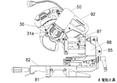
図8は、本発明の実施の形態4に係る電動工具4の左側面図である。図9は、電動工具4の右側面図である。図10は、図9のX−X断面図である。電動工具4は、コードレスタイプの卓上切断機(卓上丸鋸)であり、着脱可能に装着した電池パック50からの供給電力で動作する。電動工具4は、ベース81と、ターンテーブル82と、ホルダ85と、ガイドバー87と、支持部材88と、切断部92と、を備える。ベース81は、床面等への載置部である。ターンテーブル82は、ベース81に回動可能に連結される。ホルダ85は、ターンテーブル82の後端部付近に立設され、ターンテーブル82に対して傾動可能である。ホルダ85の上端部付近には、2本のガイドバー87が支持される。ガイドバー87には、支持部材88がスライド可能に支持される。支持部材88には、本体ハウジング92が上下に揺動自在に支持される。本体ハウジング92は、電池パック50が着脱可能であり、図示を省略した丸鋸刃を支持する。
Embodiment 4
FIG. 8 is a left side view of the power tool 4 according to Embodiment 4 of the present invention. FIG. 9 is a right side view of the power tool 4. 10 is a cross-sectional view taken along the line XX of FIG. The electric tool 4 is a cordless tabletop cutting machine (tabletop circular saw), and operates with power supplied from a
本実施の形態において、図10に示す風路CA1は、モータハウジング30の風窓31a(図9)からモータハウジング30の内部に入り、後述の風路CA5と合流し、モータ40の内部ないし近傍を通ってモータ40を冷却し、ファンガイド部32の内側を通過してファン45に至る。第2の冷却風路としての風路CA5は、本体ハウジング92の電池パック装着部の風窓92a、92bを経由し、電池パック50の風窓51aから電池パック50の内部に入り、電池ハウジング51の内部に入り、電池セル52の近傍を通って電池セル52を冷却し、風窓51b及びそれと連通するモータハウジング30の風窓31cを通ってモータハウジング30の内部に入り、風路CA1と合流する。ファン45は、本実施の形態では軸流ファンである。
In the present embodiment, the air passage CA1 shown in FIG. 10 enters the
以上、実施の形態を例に本発明を説明したが、実施の形態の各構成要素や各処理プロセスには請求項に記載の範囲で種々の変形が可能であることは当業者に理解されるところである。以下、変形例について触れる。 The present invention has been described above by taking the embodiment as an example. However, it is understood by those skilled in the art that various modifications can be made to each component and each processing process of the embodiment within the scope of the claims. By the way. Hereinafter, modifications will be described.
本発明は、携帯用切断機や卓上切断機に限定されず、モータ収容部の側方に配置される電池パックを備える電動工具全般に適用可能である。 The present invention is not limited to a portable cutting machine or a tabletop cutting machine, and can be applied to all electric tools including a battery pack disposed on the side of a motor housing portion.
1〜4 電動工具、10 ベース、20 本体ハウジング、25 ハンドルハウジング、25a グリップ部、25b トリガスイッチ、27 風路ガイド部、27a,27b 風窓、28 ギヤカバー、30 モータハウジング(モータ収容部)、31a 風窓(吸気口)、31b 風窓(排気口)、32 ファンガイド部、33 インバータ回路基板、40 モータ(ブラシレスモータ)、50 電池パック、51 電池ハウジング、51a,51b 風窓、52 電池セル、81 ベース、82 ターンテーブル、85 ホルダ、87 ガイドバー、88 支持部材、92 切断部 1-4 Power tool, 10 base, 20 body housing, 25 handle housing, 25a grip part, 25b trigger switch, 27 air path guide part, 27a, 27b wind window, 28 gear cover, 30 motor housing (motor housing part), 31a wind window (Intake port), 31b wind window (exhaust port), 32 fan guide part, 33 inverter circuit board, 40 motor (brushless motor), 50 battery pack, 51 battery housing, 51a, 51b wind window, 52 battery cell, 81 base, 82 Turntable, 85 holder, 87 guide bar, 88 support member, 92 cutting part
Claims (5)
前記モータを収容するハウジングと、
前記モータによって回転するファンと、
前記ハウジングのモータ収容部の側方に配置されて、前記モータに電力を供給する電池パックと、
前記ハウジングに設けられる第1の風窓と、
前記電池パックを冷却するための第2の風窓と、を備え、
前記ファンの回転によって、前記第1の風窓と前記ファンとを結ぶ第1の冷却風路と、前記第2の風窓と前記ファンとを結ぶ第2の冷却風路とが形成されることを特徴とする電動工具。 A motor,
A housing for housing the motor;
A fan rotated by the motor;
A battery pack disposed on the side of the motor housing portion of the housing and supplying power to the motor;
A first wind window provided in the housing;
A second wind window for cooling the battery pack,
A rotation of the fan forms a first cooling air passage connecting the first air window and the fan, and a second cooling air passage connecting the second air window and the fan. A power tool.
Priority Applications (1)
| Application Number | Priority Date | Filing Date | Title |
|---|---|---|---|
| JP2017090265A JP2018187699A (en) | 2017-04-28 | 2017-04-28 | Electric tool |
Applications Claiming Priority (1)
| Application Number | Priority Date | Filing Date | Title |
|---|---|---|---|
| JP2017090265A JP2018187699A (en) | 2017-04-28 | 2017-04-28 | Electric tool |
Publications (2)
| Publication Number | Publication Date |
|---|---|
| JP2018187699A true JP2018187699A (en) | 2018-11-29 |
| JP2018187699A5 JP2018187699A5 (en) | 2020-04-09 |
Family
ID=64479604
Family Applications (1)
| Application Number | Title | Priority Date | Filing Date |
|---|---|---|---|
| JP2017090265A Pending JP2018187699A (en) | 2017-04-28 | 2017-04-28 | Electric tool |
Country Status (1)
| Country | Link |
|---|---|
| JP (1) | JP2018187699A (en) |
Cited By (1)
| Publication number | Priority date | Publication date | Assignee | Title |
|---|---|---|---|---|
| WO2021107843A1 (en) * | 2019-11-25 | 2021-06-03 | Husqvarna Ab | A hand-held electrically powered work tool with air leaking out in a slot between the battery and battery compartment |
Citations (7)
| Publication number | Priority date | Publication date | Assignee | Title |
|---|---|---|---|---|
| JPH09272073A (en) * | 1996-04-05 | 1997-10-21 | Hitachi Koki Co Ltd | Battery-driven tool |
| JPH11288744A (en) * | 1998-03-05 | 1999-10-19 | Black & Decker Inc | Cordless power tool, detachable battery pack, charger, auxiliary moving device for fluid, and temperature changing mechanism for battery pack |
| JP2009241251A (en) * | 2008-03-28 | 2009-10-22 | Johnson Electric Sa | Power tool |
| JP2012000749A (en) * | 2010-06-15 | 2012-01-05 | Hilti Ag | Hand-held driving device |
| JP2014079873A (en) * | 2012-09-26 | 2014-05-08 | Makita Corp | Power tool |
| JP2015104216A (en) * | 2013-11-25 | 2015-06-04 | 日立工機株式会社 | Charging device |
| JP2015226941A (en) * | 2014-05-30 | 2015-12-17 | 日立工機株式会社 | Battery cooling adaptor and electric power tool |
-
2017
- 2017-04-28 JP JP2017090265A patent/JP2018187699A/en active Pending
Patent Citations (7)
| Publication number | Priority date | Publication date | Assignee | Title |
|---|---|---|---|---|
| JPH09272073A (en) * | 1996-04-05 | 1997-10-21 | Hitachi Koki Co Ltd | Battery-driven tool |
| JPH11288744A (en) * | 1998-03-05 | 1999-10-19 | Black & Decker Inc | Cordless power tool, detachable battery pack, charger, auxiliary moving device for fluid, and temperature changing mechanism for battery pack |
| JP2009241251A (en) * | 2008-03-28 | 2009-10-22 | Johnson Electric Sa | Power tool |
| JP2012000749A (en) * | 2010-06-15 | 2012-01-05 | Hilti Ag | Hand-held driving device |
| JP2014079873A (en) * | 2012-09-26 | 2014-05-08 | Makita Corp | Power tool |
| JP2015104216A (en) * | 2013-11-25 | 2015-06-04 | 日立工機株式会社 | Charging device |
| JP2015226941A (en) * | 2014-05-30 | 2015-12-17 | 日立工機株式会社 | Battery cooling adaptor and electric power tool |
Cited By (4)
| Publication number | Priority date | Publication date | Assignee | Title |
|---|---|---|---|---|
| WO2021107843A1 (en) * | 2019-11-25 | 2021-06-03 | Husqvarna Ab | A hand-held electrically powered work tool with air leaking out in a slot between the battery and battery compartment |
| WO2021107827A1 (en) * | 2019-11-25 | 2021-06-03 | Husqvarna Ab | A hand-held electrically powered work tool |
| CN113766996A (en) * | 2019-11-25 | 2021-12-07 | 胡斯华纳有限公司 | Hand-held electric power tool with air leakage in slot between battery and battery compartment |
| CN113766996B (en) * | 2019-11-25 | 2024-08-06 | 胡斯华纳有限公司 | Hand-held power tool with air leakage in slot between battery and battery compartment |
Similar Documents
| Publication | Publication Date | Title |
|---|---|---|
| CN107175724B (en) | Chain saw | |
| US7768750B2 (en) | Cordless power tool | |
| US20200086405A1 (en) | Portable machining device | |
| EP2763816B1 (en) | Battery operated handheld power tool | |
| US10220457B2 (en) | Cutting device | |
| JP6808454B2 (en) | Portable cutting machine for woodworking | |
| JP6238064B2 (en) | Electric plane | |
| US20220297209A1 (en) | Cutting tool | |
| CN109909548B (en) | Electric circular saw | |
| CN110653766A (en) | Hand-held electric tool | |
| JP5614602B2 (en) | Portable circular saw | |
| JP2018187702A (en) | Electric tool | |
| JP6508555B2 (en) | Electric tool | |
| US20140235145A1 (en) | Hand power tool | |
| CN212704725U (en) | Power tool | |
| JP2018187699A (en) | Electric tool | |
| JP7315413B2 (en) | Cutting machine | |
| US11559916B2 (en) | Electric working machine | |
| JP6534543B2 (en) | Cutting machine | |
| JP2020163780A (en) | Cutter | |
| CN217095963U (en) | Circular saw | |
| CN115365573A (en) | Hand-held electric circular saw | |
| CN115870553A (en) | Hand-held electric circular saw | |
| CN217454018U (en) | Hand-held electric circular saw | |
| CN217454017U (en) | Hand-held electric circular saw |
Legal Events
| Date | Code | Title | Description |
|---|---|---|---|
| A521 | Request for written amendment filed |
Free format text: JAPANESE INTERMEDIATE CODE: A523 Effective date: 20200228 |
|
| A621 | Written request for application examination |
Free format text: JAPANESE INTERMEDIATE CODE: A621 Effective date: 20200228 |
|
| A977 | Report on retrieval |
Free format text: JAPANESE INTERMEDIATE CODE: A971007 Effective date: 20201021 |
|
| A131 | Notification of reasons for refusal |
Free format text: JAPANESE INTERMEDIATE CODE: A131 Effective date: 20201208 |
|
| A521 | Request for written amendment filed |
Free format text: JAPANESE INTERMEDIATE CODE: A523 Effective date: 20210208 |
|
| A131 | Notification of reasons for refusal |
Free format text: JAPANESE INTERMEDIATE CODE: A131 Effective date: 20210518 |
|
| A02 | Decision of refusal |
Free format text: JAPANESE INTERMEDIATE CODE: A02 Effective date: 20211130 |