JP2018186071A - Metal/carbon nanotube composite material wire - Google Patents
Metal/carbon nanotube composite material wire Download PDFInfo
- Publication number
- JP2018186071A JP2018186071A JP2018016221A JP2018016221A JP2018186071A JP 2018186071 A JP2018186071 A JP 2018186071A JP 2018016221 A JP2018016221 A JP 2018016221A JP 2018016221 A JP2018016221 A JP 2018016221A JP 2018186071 A JP2018186071 A JP 2018186071A
- Authority
- JP
- Japan
- Prior art keywords
- strand
- conductor assembly
- composite conductor
- metal
- strands
- Prior art date
- Legal status (The legal status is an assumption and is not a legal conclusion. Google has not performed a legal analysis and makes no representation as to the accuracy of the status listed.)
- Pending
Links
Images


Classifications
-
- H—ELECTRICITY
- H01—ELECTRIC ELEMENTS
- H01B—CABLES; CONDUCTORS; INSULATORS; SELECTION OF MATERIALS FOR THEIR CONDUCTIVE, INSULATING OR DIELECTRIC PROPERTIES
- H01B5/00—Non-insulated conductors or conductive bodies characterised by their form
- H01B5/08—Several wires or the like stranded in the form of a rope
-
- H—ELECTRICITY
- H01—ELECTRIC ELEMENTS
- H01B—CABLES; CONDUCTORS; INSULATORS; SELECTION OF MATERIALS FOR THEIR CONDUCTIVE, INSULATING OR DIELECTRIC PROPERTIES
- H01B7/00—Insulated conductors or cables characterised by their form
- H01B7/02—Disposition of insulation
-
- H—ELECTRICITY
- H01—ELECTRIC ELEMENTS
- H01B—CABLES; CONDUCTORS; INSULATORS; SELECTION OF MATERIALS FOR THEIR CONDUCTIVE, INSULATING OR DIELECTRIC PROPERTIES
- H01B1/00—Conductors or conductive bodies characterised by the conductive materials; Selection of materials as conductors
- H01B1/02—Conductors or conductive bodies characterised by the conductive materials; Selection of materials as conductors mainly consisting of metals or alloys
- H01B1/023—Alloys based on aluminium
-
- H—ELECTRICITY
- H01—ELECTRIC ELEMENTS
- H01B—CABLES; CONDUCTORS; INSULATORS; SELECTION OF MATERIALS FOR THEIR CONDUCTIVE, INSULATING OR DIELECTRIC PROPERTIES
- H01B1/00—Conductors or conductive bodies characterised by the conductive materials; Selection of materials as conductors
- H01B1/02—Conductors or conductive bodies characterised by the conductive materials; Selection of materials as conductors mainly consisting of metals or alloys
- H01B1/026—Alloys based on copper
-
- H—ELECTRICITY
- H01—ELECTRIC ELEMENTS
- H01B—CABLES; CONDUCTORS; INSULATORS; SELECTION OF MATERIALS FOR THEIR CONDUCTIVE, INSULATING OR DIELECTRIC PROPERTIES
- H01B1/00—Conductors or conductive bodies characterised by the conductive materials; Selection of materials as conductors
- H01B1/04—Conductors or conductive bodies characterised by the conductive materials; Selection of materials as conductors mainly consisting of carbon-silicon compounds, carbon or silicon
-
- H—ELECTRICITY
- H01—ELECTRIC ELEMENTS
- H01B—CABLES; CONDUCTORS; INSULATORS; SELECTION OF MATERIALS FOR THEIR CONDUCTIVE, INSULATING OR DIELECTRIC PROPERTIES
- H01B5/00—Non-insulated conductors or conductive bodies characterised by their form
- H01B5/02—Single bars, rods, wires, or strips
-
- H—ELECTRICITY
- H01—ELECTRIC ELEMENTS
- H01B—CABLES; CONDUCTORS; INSULATORS; SELECTION OF MATERIALS FOR THEIR CONDUCTIVE, INSULATING OR DIELECTRIC PROPERTIES
- H01B7/00—Insulated conductors or cables characterised by their form
- H01B7/17—Protection against damage caused by external factors, e.g. sheaths or armouring
-
- H—ELECTRICITY
- H01—ELECTRIC ELEMENTS
- H01R—ELECTRICALLY-CONDUCTIVE CONNECTIONS; STRUCTURAL ASSOCIATIONS OF A PLURALITY OF MUTUALLY-INSULATED ELECTRICAL CONNECTING ELEMENTS; COUPLING DEVICES; CURRENT COLLECTORS
- H01R4/00—Electrically-conductive connections between two or more conductive members in direct contact, i.e. touching one another; Means for effecting or maintaining such contact; Electrically-conductive connections having two or more spaced connecting locations for conductors and using contact members penetrating insulation
- H01R4/10—Electrically-conductive connections between two or more conductive members in direct contact, i.e. touching one another; Means for effecting or maintaining such contact; Electrically-conductive connections having two or more spaced connecting locations for conductors and using contact members penetrating insulation effected solely by twisting, wrapping, bending, crimping, or other permanent deformation
- H01R4/18—Electrically-conductive connections between two or more conductive members in direct contact, i.e. touching one another; Means for effecting or maintaining such contact; Electrically-conductive connections having two or more spaced connecting locations for conductors and using contact members penetrating insulation effected solely by twisting, wrapping, bending, crimping, or other permanent deformation by crimping
- H01R4/183—Electrically-conductive connections between two or more conductive members in direct contact, i.e. touching one another; Means for effecting or maintaining such contact; Electrically-conductive connections having two or more spaced connecting locations for conductors and using contact members penetrating insulation effected solely by twisting, wrapping, bending, crimping, or other permanent deformation by crimping for cylindrical elongated bodies, e.g. cables having circular cross-section
Abstract
Description
本願は、2017年2月20日に出願された米国特許出願第15/436,898号の利益を要求する。 This application claims the benefit of US patent application Ser. No. 15 / 436,898, filed Feb. 20, 2017.
[0001]本発明は、概して、電線に関し、より詳細には、カーボンナノチューブより線と金属より線とから形成される複合材料電線に関する。 [0001] The present invention relates generally to electrical wires, and more particularly to composite electrical wires formed from carbon nanotube strands and metal strands.
[0002]従来の自動車用電気ケーブルは、典型的な乗用車において15〜28キログラムの質量を有し得る銅線導体を使用して製造されていた。車両質量を低減して、車両の排出要件を満たすために、車両製造業者は、アルミニウム導体も使用し始めている。しかしながら、アルミニウムワイヤ導体は、同じサイズの銅線と比べて、破壊強度および伸張強度が低く、そのため、0.75mm2(約0.5mmの直径)未満の断面を有するワイヤに対する最適な代替品とはならない。近代的な車両における多くのワイヤは、車両を通じて電力を運んでいるのではなく、デジタル信号を伝送している。データ信号回路のために選択されるワイヤの直径は、ワイヤの電気特性ではなくワイヤの機械強度要件によって決定されることが多く、回路は、小径のワイヤを使用して効率的に製造され得る。 [0002] Conventional automotive electrical cables have been manufactured using copper wire conductors that can have a mass of 15-28 kilograms in a typical passenger car. In order to reduce vehicle mass and meet vehicle emission requirements, vehicle manufacturers are also beginning to use aluminum conductors. However, aluminum wire conductors have lower fracture strength and tensile strength compared to copper wires of the same size, so they are the best alternative for wires with a cross section of less than 0.75 mm 2 (about 0.5 mm diameter) Must not. Many wires in modern vehicles carry digital signals rather than carrying power through the vehicle. The diameter of the wire selected for the data signal circuit is often determined by the mechanical strength requirements of the wire rather than the electrical properties of the wire, and the circuit can be efficiently manufactured using small diameter wires.
[0003]強度部材を利用する細長い複合材料導体または複合材料ワイヤ(例えば、金属より線と組み合わせられたアラミドファイバーより線)は、完成品の導体の強度を高めるとともに重量を低減するために使用されてきた。重量にほとんど影響を与えずに強度を高めるために、他の複合材料(例えば、ステンレス鋼より線を含むもの)が使用されてきた。しかしながら、非導電性部材(例えば、アラミドファイバー)または高抵抗部材(例えば、ステンレス鋼)を含むことは、複合材料ワイヤの全体の電気抵抗を増大させる。さらに、複合材料ワイヤは、端子上で圧着されることによる終端処理にはあまり適していない。圧着プロセス中において、非導電性部材または高抵抗部材は、ワイヤの外側部分に移動することがあり、それによって、端子とワイヤとの間の抵抗が増加してしまう。この増加は、アラミドファイバーおよびステンレス鋼より線の高い電気抵抗に起因する。 [0003] Elongated composite conductors or composite wires that utilize strength members (eg, aramid fiber strands combined with metal strands) are used to increase the strength and reduce weight of the finished conductor. I came. Other composite materials (eg, including stainless steel strands) have been used to increase strength with little impact on weight. However, including a non-conductive member (eg, aramid fiber) or a high resistance member (eg, stainless steel) increases the overall electrical resistance of the composite wire. Furthermore, composite wires are not well suited for termination by crimping on terminals. During the crimping process, the non-conductive member or high resistance member may move to the outer portion of the wire, thereby increasing the resistance between the terminal and the wire. This increase is due to the higher electrical resistance of the wires than aramid fiber and stainless steel.
[0004]より線にされたカーボンナノチューブ(CNT)は、小径のワイヤについて適切な強度を提供できる軽量の導電体である。しかしながら、CNTより線は、現在のところ、ほとんどの自動車用途について十分な導電性を提供していない。さらに、CNTより線は、端子上に圧着されることによって容易に終端処理することができない。さらに、CNTより線は、端子上にはんだ付けされることによって困難なく終端処理されない。なぜなら、それらは、容易には、はんだと濡れないからである。 [0004] Stranded carbon nanotubes (CNTs) are lightweight conductors that can provide adequate strength for small diameter wires. However, CNT strands currently do not provide sufficient conductivity for most automotive applications. Furthermore, CNT strands cannot be easily terminated by being crimped onto the terminals. Furthermore, the CNT strands are not terminated without difficulty by being soldered onto the terminals. Because they do not easily get wet with the solder.
[0005]したがって、小径ワイヤのための、銅線導体に代わる低質量の代替品が依然として望まれている。 [0005] Accordingly, there remains a need for low mass alternatives to copper wire conductors for small diameter wires.
[0006]背景技術の欄に記載された主題は、背景技術の欄において記載されていることのみから先行技術であると推定されるべきではない。同様に、背景技術の欄で述べられる問題、または、背景技術の欄の主題に関連する問題は、先行技術において従前から認識されていたものとして推定されるべきではない。背景技術の欄の主題は、様々なアプローチを表しているに過ぎず、それら自体も発明になり得る。 [0006] The subject matter described in the Background section should not be presumed to be prior art solely from the description in the Background section. Similarly, problems described in the Background section or related to the subject matter in the Background section should not be presumed as previously recognized in the prior art. The subject matter in the Background section is merely representative of various approaches, which can themselves be inventions.
[0007]本発明の一実施形態によれば、マルチより線複合材料導電体アセンブリが提供される。マルチより線複合材料導電体アセンブリは、少なくとも50ミリメートルの長さを有するカーボンナノチューブから実質的になる細長いより線と、上記カーボンナノチューブより線と実質的に同じ長さを有する細長い金属より線と、を備えている。このアセンブリは、さらに、カーボンナノチューブより線と実質的に同じ長さを有する複数の金属より線を備えていてもよい。カーボンナノチューブより線は、中央より線として配置されてもよく、複数の金属より線は、カーボンナノチューブより線を取り囲む。このアセンブリは、1つのカーボンナノチューブより線と、6つの金属より線と、からなっていてもよい。金属より線は、銅、銀、金、アルミニウムなどの材料から形成されていてもよい。金属より線は、ニッケル、スズ、銅、銀および/または金などの材料でメッキされてもよい。これに代えて、または、加えて、金属より線は、ニッケル、スズ、銅、銀および/または金などの材料で被覆されてもよい。このアセンブリは、さらに、アセンブリの端部に圧着またははんだ付けされる電気端子を備えていてもよい。このアセンブリは、金属より線およびカーボンナノチューブより線の両方を包む誘電性ポリマー材料から形成された絶縁性スリーブも備えていてもよい。 [0007] According to one embodiment of the present invention, a multi-strand composite conductor assembly is provided. A multi-strand composite conductor assembly includes an elongated strand consisting essentially of carbon nanotubes having a length of at least 50 millimeters; an elongated metal strand having a length substantially the same as the carbon nanotube strand; It has. The assembly may further comprise a plurality of metal strands having substantially the same length as the carbon nanotube strands. The carbon nanotube strands may be arranged as a strand from the center, and the plurality of metal strands surround the carbon nanotube strands. The assembly may consist of one carbon nanotube strand and six metal strands. The metal strand may be formed of a material such as copper, silver, gold, or aluminum. The metal strands may be plated with a material such as nickel, tin, copper, silver and / or gold. Alternatively or additionally, the metal strands may be coated with a material such as nickel, tin, copper, silver and / or gold. The assembly may further comprise an electrical terminal that is crimped or soldered to the end of the assembly. The assembly may also include an insulating sleeve formed from a dielectric polymer material that encloses both the metal strands and the carbon nanotube strands.
[0008]本発明が、例示目的で、添付の図面を参照して以下に説明される。 [0008] The present invention will now be described, by way of example, with reference to the accompanying drawings, in which:
[0012]より線にされたカーボンナノチューブ(CNT)導体は、より線にされた金属導体と比べて、向上された強度および低減された密度を提供する。より線にされたCNT導体は、同じ直径を有する銅より線と比べて160%高く、同じ直径を有するアルミニウムより線と比べて330%高い引張強度を有している。さらに、より線にされたCNT導体は、銅より線の16%、アルミニウムより線の52%の密度を有している。しかしながら、より線にされたCNT導体は、銅より線と比べて16.7倍高く、アルミニウムより線と比べて8.3倍高い抵抗を有しており、それによって、電気伝導性が低減される。より線にされたCNT導体の低減された電気伝導性を解決するために、複合材料導体、すなわち、1つ以上の金属より線、もしくは、金属メッキされたより線、もしくは、金属被覆されたより線を有する1つ以上のCNTより線からなる複合材料ワイヤが提供される。複合材料ワイヤのCNTより線は、複合材料ワイヤの金属より線が全体の電気伝導性を高めつつ、結果として得られる複合材料ワイヤの強度および密度を改善する。CNTより線の高い引張強度によって、特にデジタル信号伝送用途において、金属より線が適切な電気伝導性を提供しつつ、複合材料ワイヤにおけるさらに小径の金属導体が、全体で同等の引張強度を有することができる。また、CNTより線の密度が小さいことによって、金属より線と比べて重量が低減される。導電性CNTより線(単数または複数)を含むことによって、アラミドまたはステンレス鋼のより線を使用して製造された複合材料ワイヤと比べて、複合材料ワイヤの端部への電気端子の圧着取り付けの性能が改善されることが本発明者によって見出された。それは、CNTより線12が、アラミドより線とは異なり、結合的であり、ステンレス鋼より線とは異なり、銅より線と同様の圧縮性能を有しているからである。
[0012] Stranded carbon nanotube (CNT) conductors provide improved strength and reduced density compared to stranded metal conductors. Stranded CNT conductors have a tensile strength that is 160% higher than copper with the same diameter and 330% higher than aluminum wires with the same diameter. Further, the stranded CNT conductor has a density of 16% of copper strands and 52% of aluminum strands. However, stranded CNT conductors have a resistance 16.7 times higher than copper wires and 8.3 times higher than aluminum wires, thereby reducing electrical conductivity. The To overcome the reduced electrical conductivity of the stranded CNT conductor, a composite conductor, ie, one or more metal strands, or a metal-plated strand, or a metal-coated strand is used. A composite wire comprising one or more CNT strands is provided. The CNT strands of the composite wire improve the strength and density of the resulting composite wire while the metal strand of the composite wire increases overall electrical conductivity. The higher tensile strength of the CNT wires, especially in digital signal transmission applications, makes the metal strands in composite wires have the same overall tensile strength while providing adequate electrical conductivity. Can do. In addition, since the density of the wire is smaller than that of the CNT, the weight is reduced as compared with the wire than the metal. By including conductive CNT strand (s), the crimping of electrical terminals to the end of the composite wire compared to composite wire manufactured using aramid or stainless steel strands It has been found by the inventor that performance is improved. This is because the CNT
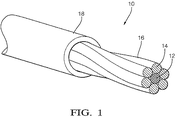
[0013]図1は、マルチより線複合材料導電体アセンブリ(以下、複合材料ワイヤ10と呼ぶ)の非限定的な例を示している。複合材料ワイヤは、1つの細長いより線12を備えている。より線12は、カーボンナノチューブから実質的になっており、少なくとも50ミリメートルの長さを有している。自動車用途では、複合材料ワイヤは、7メートルまでの長さを有していてもよい。カーボンナノチューブ(CNT)より線12は、約数ミクロンから数ミリメートルまでの長さを有するカーボンナノチューブ繊維を紡いで所望の長さおよび直径を有するより線またはヤーンにすることによって形成される。CNTより線を形成するためのプロセスは、当業者には周知の湿式紡績または乾式紡績を使用してもよい。図示される例では、CNTより線12は、6つの細長い金属より線14によって取り囲まれている。金属より線14は、カーボンナノチューブより線12と実質的に同じ長さを有する銅から形成され、CNTより線12のまわりに捻られている。本明細書で使用される場合、「実質的に同じ長さ」とは、銅より線14の長さとCNTより線12の長さとの違いが1%以下であることを意味している。さらに、本明細書で使用される場合、「銅」との用語は、元素の銅、または、銅が主成分の合金を意味している。
[0013] FIG. 1 illustrates a non-limiting example of a multi-strand composite conductor assembly (hereinafter referred to as composite wire 10). The composite wire comprises one
[0014]代替実施形態では、金属より線14は、アルミニウム、銀または金から形成されていてもよい。本明細書で使用される場合、「アルミニウム、銀および金」との用語は、当該名前の元素の元素形態、または、当該名前の元素が主成分の合金を意味している。これに加えて、または、代えて、金属より線14の外面は、他の金属材料(例えば、ニッケル、スズ、銅、銀、および/または金)でメッキまたは被覆されていてもよい。金属より線14の向上された電気伝導性を提供するため、または、耐食性を提供するために、メッキ16または被覆16が追加されてもよい。本明細書で使用される場合、「ニッケルおよびスズ」との用語は、当該名前の元素の元素形態、または、当該名前の元素が主成分の合金を意味している。金属より線14を他の金属でメッキまたは被覆するのに使用されるプロセスは、当業者に周知である。
[0014] In alternative embodiments, the
[0015]銅より線14およびCNTより線12は、誘電性材料(例えば、ポリエチレン(PE)、ポリプロピレン(PP)、ポリ塩化ビニル(PVC)、ポリアミド(NYLON)またはポリテトラフルオロエチレン(PFTE))から形成された絶縁性ジャケット18内に包み込まれる。絶縁性ジャケットは、好ましくは、0.1〜0.4ミリメートルの厚みを有していてもよい。絶縁性ジャケット18は、当業者に周知の押出成形プロセスを使用して銅より線12およびCNTより線12の上に適用されてもよい。
[0015]
[0016]図2に示されるように、複合材料ワイヤ10の端部は、電気端子20によって終端処理される。電気端子20は、一対の圧着ウィング22を有している。圧着ウィング22は、複合材料ワイヤ10の上に折り畳まれ、圧縮されて、複合材料ワイヤ10と端子20との間の圧着接続部を形成する。本発明者は、従来の圧着端子および圧着形成技術を使用して、複合材料ワイヤ10と端子20との間の十分な接続を達成することができることを見出した。代替的に、電気端子は、複合材料ワイヤの端部にはんだ付けされてもよい。
[0016] As shown in FIG. 2, the ends of the
[0017]図3は、代替実施形態の複合材料ワイヤ24を示している。図3に示されるように、単一の銅より線26が、6つのCNTより線28によって取り囲まれている。銅より線26およびCNTより線28は、誘電性材料(例えば、ポリエチレン、ポリプロピレン、ポリ塩化ビニル、ポリアミドまたはポリテトラフルオロエチレン)から形成された絶縁性ジャケット30内に包み込まれている。
[0017] Figure 3 illustrates an alternative embodiment
[0018]代替実施形態の複合材料ワイヤは、さらに多く、または、さらに少ないCNTより線と、さらに多く、または、さらに少ない金属より線と、を備えていてもよい。各タイプのより線の数および直径は、機械的強度、電気伝導性および電流容量の設計考慮事項によって決定される。複合材料ワイヤの長さは、複合材料ワイヤの具体的な用途によって決定されるであろう。 [0018] The composite wire of an alternative embodiment may comprise more or fewer CNT strands and more or fewer metal strands. The number and diameter of each type of stranded wire is determined by mechanical strength, electrical conductivity, and current capacity design considerations. The length of the composite wire will be determined by the specific application of the composite wire.
[0019]こうして、マルチより線複合材料導電体アセンブリ10すなわち複合材料ワイヤが提供される。複合材料ワイヤ10は、多くの用途(特に、デジタル信号伝送)のための適切な電気伝導性を依然として提供しつつ、金属より線ワイヤと比べて、直径および重量が低減される利益を提供する。
[0019] Thus, a multi-strand
[0020]本発明が、その好ましい実施形態について説明されたが、それは、そのように限定されることを目的としておらず、次の特許請求の範囲で提示される範囲によってのみ限定されることを意図している。さらに、第1、第2などの用語の使用は、重要性の順序を示すものではなく、1つの要素を他の要素と区別するために使用される。さらに、a、anなどの用語の使用は、量の限定を示すものではなく、言及される物の少なくとも1つの存在を示している。さらに、方向用語、例えば、上部、下部などは、特定の向きを示すものではなく、1つの要素を他の要素から区別し、さまざまな要素間の位置的な関係を規定するために使用される。 [0020] Although the invention has been described with reference to preferred embodiments thereof, it is not intended to be so limited, but only by the scope presented in the following claims. Intended. Furthermore, the use of terms such as first, second, etc. does not indicate the order of importance, but is used to distinguish one element from another. Furthermore, the use of terms such as a, an, etc. does not indicate a limitation of quantity, but indicates the presence of at least one of the mentioned items. Furthermore, directional terms, such as top, bottom, etc., do not indicate a particular orientation, but are used to distinguish one element from another and to define positional relationships between various elements. .
Claims (10)
少なくとも50ミリメートルの長さを有するカーボンナノチューブから実質的になる細長いより線(12)と、
前記カーボンナノチューブより線(12)と実質的に同じ長さを有する細長い金属より線(14)と
を備えるマルチより線複合材料導電体アセンブリ。 A multi-strand composite conductor assembly (10) comprising:
An elongated strand (12) consisting essentially of carbon nanotubes having a length of at least 50 millimeters;
A multi-strand composite conductor assembly comprising: an elongated metal strand (14) having substantially the same length as the carbon nanotube strand (12).
さらに、前記カーボンナノチューブより線(12)と実質的に同じ長さを有する複数の金属より線(14)を備える
マルチより線複合材料導電体アセンブリ。 A multi-strand composite conductor assembly (10) according to claim 1, comprising:
The multi-stranded composite conductor assembly further comprising a plurality of metal strands (14) having substantially the same length as the carbon nanotube strands (12).
前記カーボンナノチューブより線(12)は、中央より線(12)であり、
前記複数の金属より線(14)は、前記カーボンナノチューブより線(12)を取り囲む
マルチより線複合材料導電体アセンブリ。 A multi-strand composite conductor assembly (10) according to claim 2, comprising:
The carbon nanotube strand (12) is the center strand (12);
The plurality of metal strands (14) surrounds the carbon nanotube strands (12). A multi-strand composite conductor assembly.
前記マルチより線複合材料導電体アセンブリ(10)は、1つのカーボンナノチューブより線(12)と、6つの金属より線(14)と、からなる
マルチより線複合材料導電体アセンブリ。 A multi-strand composite conductor assembly (10) according to claim 3,
The multi-strand composite conductor assembly (10) comprises a multi-strand composite conductor assembly comprising one carbon nanotube strand (12) and six metal strands (14).
前記金属より線(14)は、銅、銀、金およびアルミニウムからなる群から選択される材料から形成されている
マルチより線複合材料導電体アセンブリ。 A multi-strand composite conductor assembly (10) according to claim 1, comprising:
The metal strand (14) is formed from a material selected from the group consisting of copper, silver, gold and aluminum.
前記金属より線(14)は、ニッケル、スズ、銅、銀および金からなる群から選択される材料によってメッキされている
マルチより線複合材料導電体アセンブリ。 A multi-strand composite conductor assembly (10) according to claim 5,
The metal strand (14) is plated with a material selected from the group consisting of nickel, tin, copper, silver and gold. Multi-strand composite conductor assembly.
前記金属より線(14)は、ニッケル、スズ、銅、銀および金からなる群から選択される材料によって被覆されている
マルチより線複合材料導電体アセンブリ。 A multi-strand composite conductor assembly (10) according to claim 5,
The multi-strand composite conductor assembly wherein the metal strand (14) is coated with a material selected from the group consisting of nickel, tin, copper, silver and gold.
さらに、前記マルチより線複合材料導電体アセンブリ(10)の端部に圧着された電気端子(20)を備える
マルチより線複合材料導電体アセンブリ。 A multi-strand composite conductor assembly (10) according to claim 1, comprising:
The multi-strand composite conductor assembly further comprises an electrical terminal (20) crimped to an end of the multi-strand composite conductor assembly (10).
さらに、前記マルチより線複合材料導電体アセンブリ(10)の端部にはんだ付けされた電気端子(20)を備える
マルチより線複合材料導電体アセンブリ。 A multi-strand composite conductor assembly (10) according to claim 1, comprising:
The multi-strand composite conductor assembly further comprising an electrical terminal (20) soldered to an end of the multi-strand composite conductor assembly (10).
さらに、誘電性ポリマー材料から形成され、前記金属より線(14)および前記カーボンナノチューブより線(12)を包む絶縁性スリーブを備える
マルチより線複合材料導電体アセンブリ。 A multi-strand composite conductor assembly (10) according to claim 1, comprising:
A multi-strand composite conductor assembly further comprising an insulating sleeve formed from a dielectric polymer material and enclosing the metal strand (14) and the carbon nanotube strand (12).
Applications Claiming Priority (2)
| Application Number | Priority Date | Filing Date | Title |
|---|---|---|---|
| US15/436,898 | 2017-02-20 | ||
| US15/436,898 US10109391B2 (en) | 2017-02-20 | 2017-02-20 | Metallic/carbon nanotube composite wire |
Publications (2)
| Publication Number | Publication Date |
|---|---|
| JP2018186071A true JP2018186071A (en) | 2018-11-22 |
| JP2018186071A5 JP2018186071A5 (en) | 2020-02-06 |
Family
ID=61386676
Family Applications (1)
| Application Number | Title | Priority Date | Filing Date |
|---|---|---|---|
| JP2018016221A Pending JP2018186071A (en) | 2017-02-20 | 2018-02-01 | Metal/carbon nanotube composite material wire |
Country Status (5)
| Country | Link |
|---|---|
| US (1) | US10109391B2 (en) |
| EP (1) | EP3364422B1 (en) |
| JP (1) | JP2018186071A (en) |
| KR (1) | KR102005669B1 (en) |
| CN (1) | CN108461171B (en) |
Cited By (2)
| Publication number | Priority date | Publication date | Assignee | Title |
|---|---|---|---|---|
| JP2020167101A (en) * | 2019-03-29 | 2020-10-08 | 古河電気工業株式会社 | Carbon nanotube wire |
| WO2021201096A1 (en) * | 2020-03-31 | 2021-10-07 | 古河電気工業株式会社 | Connection structure for carbon nanotube wire |
Families Citing this family (8)
| Publication number | Priority date | Publication date | Assignee | Title |
|---|---|---|---|---|
| USD852456S1 (en) * | 2016-12-19 | 2019-07-02 | Mars, Incorporated | Food product |
| US10128022B1 (en) * | 2017-10-24 | 2018-11-13 | Northrop Grumman Systems Corporation | Lightweight carbon nanotube cable comprising a pair of plated twisted wires |
| FR3086791A1 (en) * | 2018-09-27 | 2020-04-03 | Nexans | CARBON-METAL MULTIBRIN CONDUCTIVE CORE FOR ELECTRIC CABLE |
| WO2020074992A1 (en) * | 2018-10-08 | 2020-04-16 | 3M Innovative Properties Company | Coil construction for automotive wireless charging |
| JP2021034296A (en) | 2019-08-28 | 2021-03-01 | 株式会社デンソー | Conducting wire and coil member |
| WO2021134483A1 (en) * | 2019-12-31 | 2021-07-08 | 瑞仪光电(苏州)有限公司 | Suspension cable structure and lighting device |
| CN115298904A (en) * | 2020-05-27 | 2022-11-04 | 古河电气工业株式会社 | Terminal-equipped electric wire, wire harness, terminal crimping die, and method for manufacturing terminal-equipped electric wire |
| US20230335307A1 (en) * | 2020-09-14 | 2023-10-19 | Nexans | Process for manufacturing a carbon-metal composite material and use thereof for manufacturing an electric cable |
Citations (2)
| Publication number | Priority date | Publication date | Assignee | Title |
|---|---|---|---|---|
| US20070284987A1 (en) * | 2006-06-09 | 2007-12-13 | Tsinghua University | Field emission element and manufacturing method thereof |
| US20140224524A1 (en) * | 2013-02-11 | 2014-08-14 | Tyco Electronics Corporation | Composite cable |
Family Cites Families (27)
| Publication number | Priority date | Publication date | Assignee | Title |
|---|---|---|---|---|
| SE0001123L (en) * | 2000-03-30 | 2001-10-01 | Abb Ab | Power cable |
| KR200291382Y1 (en) * | 2002-07-20 | 2002-10-09 | 문인환 | A soldering device of connector and seme-rigid cable |
| KR101458846B1 (en) * | 2004-11-09 | 2014-11-07 | 더 보드 오브 리전츠 오브 더 유니버시티 오브 텍사스 시스템 | The fabrication and application of nanofiber ribbons and sheets and twisted and non-twisted nanofiber yarns |
| BRPI0610076A2 (en) * | 2005-04-22 | 2010-05-25 | Univ California | nanotubes as microwave frequency interconnections |
| TWI298520B (en) | 2005-09-12 | 2008-07-01 | Ind Tech Res Inst | Method of making an electroplated interconnection wire of a composite of metal and carbon nanotubes |
| US8013247B2 (en) * | 2006-04-25 | 2011-09-06 | The Mitre Corporation | Carbon nanotube-based electronic devices |
| US7408116B2 (en) * | 2006-06-23 | 2008-08-05 | Delphi Technologies, Inc. | Insulated non-halogenated heavy metal free vehicular cable |
| CN101286385B (en) * | 2007-04-11 | 2010-05-26 | 清华大学 | Electromagnetic shielding cable |
| JP2008277195A (en) | 2007-05-02 | 2008-11-13 | Kurabe Ind Co Ltd | Electric wire conductor, and insulated electric wire |
| CN101499331A (en) * | 2008-02-01 | 2009-08-05 | 北京富纳特创新科技有限公司 | Cable |
| KR101276898B1 (en) * | 2008-02-01 | 2013-06-19 | 혼하이 프리시젼 인더스트리 컴퍼니 리미티드 | Carbon nanotube composite material and methods for making the same |
| EP2279512B1 (en) * | 2008-05-07 | 2019-10-23 | Nanocomp Technologies, Inc. | Carbon nanotube-based coaxial electrical cables and wiring harness |
| MX2008013821A (en) * | 2008-10-28 | 2010-04-28 | Magnekon S A De C V | Magnet wire with coating added with fullerene-type nanostructures. |
| US8445788B1 (en) * | 2009-01-05 | 2013-05-21 | The Boeing Company | Carbon nanotube-enhanced, metallic wire |
| US9111658B2 (en) * | 2009-04-24 | 2015-08-18 | Applied Nanostructured Solutions, Llc | CNS-shielded wires |
| JP2012531015A (en) * | 2009-06-19 | 2012-12-06 | スリーエム イノベイティブ プロパティズ カンパニー | Shielded electrical cable |
| US8354593B2 (en) * | 2009-07-10 | 2013-01-15 | Nanocomp Technologies, Inc. | Hybrid conductors and method of making same |
| CN101998200A (en) * | 2009-08-25 | 2011-03-30 | 鸿富锦精密工业(深圳)有限公司 | Earphone line and earphone with same |
| JP5876993B2 (en) | 2010-05-25 | 2016-03-02 | 矢崎総業株式会社 | Conductive material and method for producing conductive material |
| CN102372253B (en) | 2010-08-23 | 2014-01-15 | 清华大学 | Carbon nano tube compound linear structure and preparation method thereof |
| CN102063959B (en) * | 2010-11-18 | 2013-02-13 | 清华大学 | Cable |
| US8853540B2 (en) * | 2011-04-19 | 2014-10-07 | Commscope, Inc. Of North Carolina | Carbon nanotube enhanced conductors for communications cables and related communications cables and methods |
| US20130048337A1 (en) * | 2011-08-24 | 2013-02-28 | Tyco Electronics Corporation | Carbon-based substrates with organometallic fillers |
| CN202205480U (en) | 2011-09-13 | 2012-04-25 | 常熟泓淋电线电缆有限公司 | Round copper wire stranded wire |
| US8808792B2 (en) * | 2012-01-17 | 2014-08-19 | Northrop Grumman Systems Corporation | Carbon nanotube conductor with enhanced electrical conductivity |
| KR20140137369A (en) * | 2012-02-22 | 2014-12-02 | 셀던 테크놀로지, 인코포레이티드. | Electrodes and applications |
| US9685258B2 (en) * | 2012-11-09 | 2017-06-20 | Northrop Grumman Systems Corporation | Hybrid carbon nanotube shielding for lightweight electrical cables |
-
2017
- 2017-02-20 US US15/436,898 patent/US10109391B2/en active Active
-
2018
- 2018-02-01 JP JP2018016221A patent/JP2018186071A/en active Pending
- 2018-02-08 EP EP18155873.5A patent/EP3364422B1/en active Active
- 2018-02-13 CN CN201810150452.6A patent/CN108461171B/en active Active
- 2018-02-20 KR KR1020180019634A patent/KR102005669B1/en active IP Right Grant
Patent Citations (2)
| Publication number | Priority date | Publication date | Assignee | Title |
|---|---|---|---|---|
| US20070284987A1 (en) * | 2006-06-09 | 2007-12-13 | Tsinghua University | Field emission element and manufacturing method thereof |
| US20140224524A1 (en) * | 2013-02-11 | 2014-08-14 | Tyco Electronics Corporation | Composite cable |
Cited By (3)
| Publication number | Priority date | Publication date | Assignee | Title |
|---|---|---|---|---|
| JP2020167101A (en) * | 2019-03-29 | 2020-10-08 | 古河電気工業株式会社 | Carbon nanotube wire |
| JP7269070B2 (en) | 2019-03-29 | 2023-05-08 | 古河電気工業株式会社 | carbon nanotube wire |
| WO2021201096A1 (en) * | 2020-03-31 | 2021-10-07 | 古河電気工業株式会社 | Connection structure for carbon nanotube wire |
Also Published As
| Publication number | Publication date |
|---|---|
| EP3364422A1 (en) | 2018-08-22 |
| US20180240569A1 (en) | 2018-08-23 |
| KR20180096525A (en) | 2018-08-29 |
| US10109391B2 (en) | 2018-10-23 |
| CN108461171B (en) | 2022-02-11 |
| EP3364422B1 (en) | 2020-05-13 |
| CN108461171A (en) | 2018-08-28 |
| KR102005669B1 (en) | 2019-07-30 |
Similar Documents
| Publication | Publication Date | Title |
|---|---|---|
| CN108461171B (en) | Metal/carbon nano tube composite wire | |
| US10115492B2 (en) | Electrically conductive carbon nanotube wire having a metallic coating and methods of forming same | |
| JP2018186071A5 (en) | ||
| JP3719163B2 (en) | Twisted wire conductor for movable part wiring material and cable using the same | |
| WO2007060953A1 (en) | Crimp-style terminal for aluminum strand and terminal structure of aluminum strand having the crimp-style terminal connected thereto | |
| JP2009152140A (en) | Composite electric wire | |
| JP4044805B2 (en) | Flat shielded cable | |
| CN101313372A (en) | Electric wire for automobile | |
| US10242766B2 (en) | Highly bendable insulated electric wire and wire harness | |
| US9293233B2 (en) | Composite cable | |
| WO2006022117A1 (en) | Coaxial cable | |
| JP2000228116A (en) | Electric wire conductor for harness | |
| JP2012003853A (en) | Coated wire, and assembly of coated wire and terminal | |
| JP2014150022A (en) | Insulated wire | |
| CN110783026A (en) | Insulated wire and cable | |
| JP2004087436A (en) | Aluminum cable for automobile | |
| JPS6129133Y2 (en) | ||
| CN106575535A (en) | Electrical conductor for aeronautical applications | |
| CN212541927U (en) | High-strength wire | |
| CN217933200U (en) | Be applicable to ultrasonic bonding high tension cable for new energy automobile | |
| CN209947451U (en) | Stranded wire and stranded wire cable | |
| JP7295817B2 (en) | Conductor stranded wire for wire harness | |
| CN220709988U (en) | Strong torsion power cable | |
| RU205212U1 (en) | ONBOARD AIRCRAFT ELECTRIC WIRE | |
| RU204344U1 (en) | ONBOARD AIRCRAFT ELECTRIC WIRE |
Legal Events
| Date | Code | Title | Description |
|---|---|---|---|
| A621 | Written request for application examination |
Free format text: JAPANESE INTERMEDIATE CODE: A621 Effective date: 20180618 |
|
| A711 | Notification of change in applicant |
Free format text: JAPANESE INTERMEDIATE CODE: A711 Effective date: 20190206 |
|
| RD03 | Notification of appointment of power of attorney |
Free format text: JAPANESE INTERMEDIATE CODE: A7423 Effective date: 20190207 |
|
| RD04 | Notification of resignation of power of attorney |
Free format text: JAPANESE INTERMEDIATE CODE: A7424 Effective date: 20190208 |
|
| A977 | Report on retrieval |
Free format text: JAPANESE INTERMEDIATE CODE: A971007 Effective date: 20190516 |
|
| A131 | Notification of reasons for refusal |
Free format text: JAPANESE INTERMEDIATE CODE: A131 Effective date: 20190619 |
|
| A601 | Written request for extension of time |
Free format text: JAPANESE INTERMEDIATE CODE: A601 Effective date: 20190918 |
|
| A524 | Written submission of copy of amendment under article 19 pct |
Free format text: JAPANESE INTERMEDIATE CODE: A524 Effective date: 20191219 |
|
| A02 | Decision of refusal |
Free format text: JAPANESE INTERMEDIATE CODE: A02 Effective date: 20200106 |