JP2018176280A - System and method for arc welding and wire manipulation control - Google Patents
System and method for arc welding and wire manipulation control Download PDFInfo
- Publication number
- JP2018176280A JP2018176280A JP2018073033A JP2018073033A JP2018176280A JP 2018176280 A JP2018176280 A JP 2018176280A JP 2018073033 A JP2018073033 A JP 2018073033A JP 2018073033 A JP2018073033 A JP 2018073033A JP 2018176280 A JP2018176280 A JP 2018176280A
- Authority
- JP
- Japan
- Prior art keywords
- wire
- welding
- parameter
- rate
- average
- Prior art date
- Legal status (The legal status is an assumption and is not a legal conclusion. Google has not performed a legal analysis and makes no representation as to the accuracy of the status listed.)
- Pending
Links
Images


Classifications
-
- B—PERFORMING OPERATIONS; TRANSPORTING
- B23—MACHINE TOOLS; METAL-WORKING NOT OTHERWISE PROVIDED FOR
- B23K—SOLDERING OR UNSOLDERING; WELDING; CLADDING OR PLATING BY SOLDERING OR WELDING; CUTTING BY APPLYING HEAT LOCALLY, e.g. FLAME CUTTING; WORKING BY LASER BEAM
- B23K9/00—Arc welding or cutting
- B23K9/24—Features related to electrodes
- B23K9/26—Accessories for electrodes, e.g. ignition tips
-
- B—PERFORMING OPERATIONS; TRANSPORTING
- B23—MACHINE TOOLS; METAL-WORKING NOT OTHERWISE PROVIDED FOR
- B23K—SOLDERING OR UNSOLDERING; WELDING; CLADDING OR PLATING BY SOLDERING OR WELDING; CUTTING BY APPLYING HEAT LOCALLY, e.g. FLAME CUTTING; WORKING BY LASER BEAM
- B23K9/00—Arc welding or cutting
- B23K9/12—Automatic feeding or moving of electrodes or work for spot or seam welding or cutting
- B23K9/124—Circuits or methods for feeding welding wire
- B23K9/125—Feeding of electrodes
-
- B—PERFORMING OPERATIONS; TRANSPORTING
- B23—MACHINE TOOLS; METAL-WORKING NOT OTHERWISE PROVIDED FOR
- B23K—SOLDERING OR UNSOLDERING; WELDING; CLADDING OR PLATING BY SOLDERING OR WELDING; CUTTING BY APPLYING HEAT LOCALLY, e.g. FLAME CUTTING; WORKING BY LASER BEAM
- B23K9/00—Arc welding or cutting
- B23K9/06—Arrangements or circuits for starting the arc, e.g. by generating ignition voltage, or for stabilising the arc
- B23K9/073—Stabilising the arc
-
- B—PERFORMING OPERATIONS; TRANSPORTING
- B23—MACHINE TOOLS; METAL-WORKING NOT OTHERWISE PROVIDED FOR
- B23K—SOLDERING OR UNSOLDERING; WELDING; CLADDING OR PLATING BY SOLDERING OR WELDING; CUTTING BY APPLYING HEAT LOCALLY, e.g. FLAME CUTTING; WORKING BY LASER BEAM
- B23K9/00—Arc welding or cutting
- B23K9/09—Arrangements or circuits for arc welding with pulsed current or voltage
-
- B—PERFORMING OPERATIONS; TRANSPORTING
- B23—MACHINE TOOLS; METAL-WORKING NOT OTHERWISE PROVIDED FOR
- B23K—SOLDERING OR UNSOLDERING; WELDING; CLADDING OR PLATING BY SOLDERING OR WELDING; CUTTING BY APPLYING HEAT LOCALLY, e.g. FLAME CUTTING; WORKING BY LASER BEAM
- B23K9/00—Arc welding or cutting
- B23K9/095—Monitoring or automatic control of welding parameters
- B23K9/0953—Monitoring or automatic control of welding parameters using computing means
-
- B—PERFORMING OPERATIONS; TRANSPORTING
- B23—MACHINE TOOLS; METAL-WORKING NOT OTHERWISE PROVIDED FOR
- B23K—SOLDERING OR UNSOLDERING; WELDING; CLADDING OR PLATING BY SOLDERING OR WELDING; CUTTING BY APPLYING HEAT LOCALLY, e.g. FLAME CUTTING; WORKING BY LASER BEAM
- B23K9/00—Arc welding or cutting
- B23K9/32—Accessories
Abstract
Description
本発明に適合する装置、システム、及び方法は溶接に関し、より具体的には、溶接作業中のワイヤ操作の制御に関する装置、システム、及び方法に関する。 Apparatus, systems and methods consistent with the present invention relate to welding, and more particularly to apparatus, systems and methods related to control of wire operations during welding operations.
多くの溶接分野において、ワイヤ操作はより一般的となりつつある。ワイヤ操作は、消耗ワイヤ/電極が溶接工程中の様々な段階で前進させ、引き戻される際に行われる。例えば、あるGMAW/MIG溶接作業では、電極は、短絡が起こるか、検出されるまで前進させられ、その後、短絡の解消を助けるために引き戻される。一部の工程の中で、これは、短絡をより素早く解消するのに役立ち、その結果、全体的により低い入熱で溶接作業を行うことができる。しかしながら、このような分野では、ワイヤ制御方法から、溶接中の溶着速度が一貫しない等、溶接中に問題が発生することがある。これは、一部の溶接において、コンタクトチップから加工物までの距離(CTWD:contact tip to work distance)が変化すると発生することが多く、これは、それによって溶接作業の短絡回数が変わる可能性があるからである。 In many welding applications, wire handling is becoming more common. Wire manipulation occurs as the consumable wire / electrode is advanced and pulled back at various stages during the welding process. For example, in some GMAW / MIG welding operations, the electrodes are advanced until a short circuit occurs or is detected, and then pulled back to help eliminate the short circuit. In some processes, this helps to eliminate shorts more quickly, so that the welding operation can be performed with a lower overall heat input. However, in such fields, problems may occur during welding, such as inconsistent deposition rates during welding due to wire control methods. This often occurs when the contact tip to work distance (CTWD) changes in some welds, which can change the number of shorts in the welding operation. It is because there is.
従来の、伝統的な、すでに提案されている方式の別の限界や欠点は、これらの方式を、図面に関する本願の後述の本発明の実施形態と比較すれば、当業者にとって明らかとなるであろう。 Other limitations and disadvantages of the conventional, already proposed schemes will become apparent to those skilled in the art when comparing these schemes with the later-described embodiments of the present invention with reference to the drawings. I will.
本発明のある例示的実施形態は、溶接工程中のワイヤ送給及びワイヤ操作を、溶接作業の平均ワイヤ送給速度が所望の速度で保持され、いくつかの実施形態においては電圧又は電流等の溶接パラメータに関係なく制御されるように制御する方法とシステムである。 Certain exemplary embodiments of the present invention maintain wire feed and wire operation during the welding process, with the average wire feed rate of the welding operation being maintained at the desired rate, and in some embodiments such as voltage or current. A method and system for controlling to be controlled regardless of welding parameters.
本発明の上記及び/又はその他の態様は、下記のような添付の図面に関する本発明の例示的実施形態の詳細な説明によって、より明らかとなるであろう。 The above and / or other aspects of the present invention will become more apparent from the detailed description of the exemplary embodiments of the present invention with reference to the attached drawings as follows.
ここで、各種の代替的な実施形態と添付の図面を参照するが、同様の数字は実質的に同じ構造的要素を示す。各例は、限定ではなく、説明のために提供されている。実際に、当業者にとっては、開示と特許請求の範囲の範囲又は主旨から逸脱することなく、改良や変更が可能であることが明らかであろう。例えば、図や説明文において1つの実施形態の一部とされている特徴は、他の実施形態で使用して、また別の実施形態を創出してもよい。それゆえ、本開示は、付属の特許請求の範囲とその同等物の範囲内に含まれる改良や変更を含むことが意図されている。 Reference is now made to various alternative embodiments and the accompanying drawings, in which like numerals indicate substantially similar structural elements. Each example is provided by way of illustration, not limitation. Indeed, it will be apparent to one skilled in the art that modifications and variations can be made without departing from the scope or spirit of the disclosure and claims. For example, features that are part of one embodiment in the drawings and description may be used in other embodiments to create other embodiments. Therefore, the present disclosure is intended to cover the modifications and variations included within the scope of the appended claims and their equivalents.
本開示は一般に、溶接システム及び溶接工程に関する。具体的には、本発明の実施形態は、GMAW/MIG等の溶接システムに関する。しかしながら、本明細書中、下記の実施形態においていずれかの具体的な溶接作業の種類が論じられている場合、その議論は例であり、本発明の他の例示的実施形態にとって限定的ではないことが意図されている点に留意されたい。 The present disclosure relates generally to welding systems and processes. Specifically, embodiments of the present invention relate to welding systems such as GMAW / MIG. However, where any specific type of welding operation is discussed herein in the embodiments below, the discussion is exemplary and not limiting to other exemplary embodiments of the present invention. Note that it is intended.
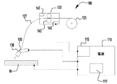
ここで、本発明の例示的溶接システムである図1を参照する。溶接システム100は溶接電源110を含み、これはプロセッサベースのコントローラ115とユーザインタフェース/ディスプレイ111を有する。電源は、何れの種類の既知の溶接電源とすることもでき、本発明の実施形態はこれに限定されない。例えば、電源100は、オハイオ州クリーブランドのThe Lincoln Electric Companyが製造するPowerWaveとすることができるが、実施形態はこれに限定されない。強力で高度なコントローラを備えるこのような電源の製造、構成、動作は知られているため、これらについて本明細書では詳しく説明する必要はない。コントローラ115は、溶接システムの動作を制御できる何れの既知のプロセッサセッサベースのコントローラとすることもでき、CPU、メモリ等を有することができる。ディスプレイ111は、溶接作業、使用者の入力データ等に関する動作データを表示する何れの既知の種類のディスプレイとすることもできる。ディスプレイはまた、使用者が入力データをスクリーン111から入力できるように、タッチスクリーン型とすることもできる。
Reference is now made to FIG. 1, which is an exemplary welding system of the present invention. The
システム100はまた、消耗材供給源125も含むことができ、そこから消耗材127が、よく知られた動作のワイヤフィーダ120を通じて溶接作業へと供給される。ワイヤフィーダ120もまた、コントローラ145を含むことができ、これは電源110のコントローラ115に連結できる。このような実施形態では、データ、情報、及び制御コマンド/命令をそれぞれのコントローラ間で交換できる。ワイヤフィーダ120はまた、ユーザインタフェース147も有することができ、それによって使用者は入力制御情報及び溶接工程データをワイヤフィーダ120に入力できる。それぞれのコントローラ間の通信のための連結(これは、有線、無線、又は電源ケーブルによるもの等、何れの既知の手段を通じたものとすることもできる)により、使用者はワイヤフィーダ120又は電源110の何れを介しても溶接作業を制御できる。このような構成は一般に知られており、本明細書で詳しく説明する必要はない。ワイヤ127は、加工物又は溶接金属Wの溶接のための何れかの既知の種類の溶接トーチ130に供給される。図のように、またよく知られているように、ワイヤフィーダ120は、本明細書に記載されているように消耗材127を前進させ、引き戻すことができるワイヤ駆動機構143を有する。このようなシステムは、モータ、サーボ、ローラ等を使用することができ、これらがワイヤ127を把持し、ワイヤを前進又は引戻し方向に駆動する。溶接作業は広く知られているため、これらについて本明細書では詳しく説明しない。
The
さらに、いくつかの例示的実施形態において、溶接トーチ130は、ワイヤの前進及び引戻しを支援できるワイヤ駆動機構150を有することができる。このような「プッシュプル」型トーチは知られており、本明細書で詳しく説明する必要はない。さらに、トーチは、ワイヤ駆動機構150又は、トーチ130の中のその他の同様の適当な機構を使って、溶接作業のワイヤ送給速度に関するフィードバックを提供できる。もちろん、フィードバックシステムが消耗材127のワイヤ送給速度を正確にモニタできるかぎり、ワイヤフィーダ内のシステム等、他の既知のシステムを使ってワイヤ送給速度フィードバックを提供することもできる。例示的実施形態において、ワイヤ送給速度フィードバックシステム(例えば、150)は、検出されたワイヤ送給速度をワイヤフィーダ120のコントローラ145に提供し、するとこれが所望の持続時間の平均ワイヤ送給速度を判定できる。
Additionally, in some exemplary embodiments,
上で説明したように、溶接作業の中には、溶接作業中にワイヤ127を前進させ、及び引き戻して、所望の溶接特性及び/又は溶接性能を提供することが望ましいものがある。例えば、状況により、溶接中の短絡イベントの検出中及び/または検出時に消耗材を引き戻すことが望ましい場合がある。これは、短絡をより素早く解消するのを助けることができる。しかしながら、溶接中に短絡回数が変化する可能性があるため、溶接作業のワイヤ供給速度が変更される。例えば、溶接中、CTWDを(例えば、手動又は半自動溶接作業中に)変更でき、これらの変更によって、短絡回数と、したがって平均ワイヤ送給速度が変化する。例えば、短絡回数が減ると、ワイヤの引戻しイベントが減るため、平均ワイヤ送給速度が高くなる可能性があり、その逆でもある。これらの変化の結果、溶接作業中に、ある溶接速度等についてについて金属溶接が一定でなくなることがある。これらの変化はまた、溶接工程に対するその他の不利な影響の原因にもなりうる。
As discussed above, in some welding operations, it may be desirable to advance and pull back the
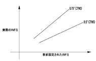
図2は、それぞれCTWDが0.5インチと0.75インチの場合の、所望の、又は事前設定されたワイヤ送給速度と平均ワイヤ送給速度の相対的関係を示している。図からわかるように、CTWDに応じて、所望のワイヤ送給速度と平均ワイヤ送給速度との関係を定義する勾配が変化する。これは、ある溶接作業に関する短絡回数の違いによる可能性があり、これはCTWDの違いによる。 FIG. 2 shows the relative relationship between the desired or preset wire delivery rate and the average wire delivery rate for CTWDs of 0.5 inch and 0.75 inch, respectively. As can be seen from the figure, depending on the CTWD, the slope defining the relationship between the desired wire delivery rate and the average wire delivery rate changes. This may be due to differences in the number of shorts for a given welding operation, which is due to differences in CTWD.
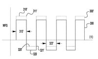
ここで、図3を参照すると、本発明のある実施形態による例示的なワイヤ送給速度波形300が示されている。図のように、波形300は複数の正のパルス310と負のパルス320を有し、正のパルスはワイヤの前進を表し、負のパルスはワイヤの引戻しを表す。正のパルス310は各々、ピークWFS311と持続時間313を有し、負のパルス320はピーク引戻し速度321と持続時間323を有する。もちろん、留意すべき点は、例示的実施形態において、それぞれのパルスの持続時間は必ずしも一定ではなく、溶接工程の短絡回数、短絡持続時間等により決まる可能性がある。しかしながら、ピークWFSの値の各々は、溶接作業の前に決定することができ、使用者が設定できるか、又は溶接作業に関する使用者の入力データに基づいてそれぞれのコントローラのうちの1つが決定できる。
Referring now to FIG. 3, an exemplary wire
図3にはまた、実際の/検出されたWFS 340と比較して、破線で示される所望の平均WFS 330の図式図も示されている。平均WFS 330はある期間の平均を表し、これは、コントローラの何れか又は両方の中で事前に決定でき、検出された平均WFS 340は、溶接作業のための実際の平均WFSを表す。図3において、実際の平均340は、所望の平均330より低いことが示されている。これは、CTWDが所望のものより短いことによる可能性があり、その結果、溶接作業の短絡回数が増大しうる。このように短絡回数が増えることにより、ワイヤが前進時より引戻し状態において長い時間を費やすことになり、それゆえ、実際の平均WFSが所望の値より低くなる。図の実施形態において、その結果である溶接は、溶接に追加される消耗材が少なくなるため、溶接速度が所望の値より低くなる可能性が高い。本発明の実施形態はこれに対応するものであり、それについて以下にさらに説明する。
Also shown in FIG. 3 is a schematic of the desired
図4は、本発明の例示的な波形を示す。図3の波形300が背景として示されている。図のように、本明細書に記載のシステムは、WFS波形を調整して所望の平均WFSを得る。これは、WFSパルスの前進及び引戻しピークを増減することにより実行できる。例えば、検出された平均WFSを高めるために、システムは、波形がより大きい正のピークピーク311’とより小さい負のピーク321’を有するようにすることができる。これによって、溶接作業の平均WFSが高くなる。検出された平均WFSを下げるためには、正のピークを小さくすることができ、負のピークを大きくすることができる。この調整方法を使用することにより、本発明の実施形態は溶接作業の電流及び/又は電圧の制御とは関係なく、溶接工程のワイヤ操作中のWFS制御の改善を実現できる。
FIG. 4 shows an exemplary waveform of the present invention. The
具体的には、いくつかの例示的実施形態において、溶接アーク電流及び/又は電圧制御は、ワイヤ送給速度とは別に調整される。すなわち、このようなシステムにおいて、電源及び/又はワイヤフィーダは、電圧及び/又は電流フィードバック及び制御回路と、所望の電流帯/又は電圧を保持することのできるシステムを有する。このようなシステムはすでに知られており、本明細書で詳しく説明する必要はない。いくつかの例示的実施形態において、アーク電圧及び電流のフィードバックと制御は、本明細書に記載されているように、ワイヤ送給速度制御とは完全に別である。これは、電圧及び/又は電流の何れも調整されないという意味ではなく、ワイヤ送給速度がアーク電圧及び/又は電流フィードバックに基づいて直接調整されず、アーク電圧及び/又は電流か検出されたワイヤ送給速度に基づいて直接制御されない、ということである。このようなシステムは、システムの動作効率を改善し、それによって本明細書に記載されているシステムは溶接作業中の消耗材の一貫した溶着を提供するように所望の方法でワイヤ送給速度を調整できる。 Specifically, in some exemplary embodiments, the welding arc current and / or voltage control is adjusted separately from the wire feed rate. That is, in such a system, the power supply and / or wire feeder has a voltage and / or current feedback and control circuit and a system capable of maintaining a desired current band / or voltage. Such systems are already known and need not be described in detail herein. In some exemplary embodiments, feedback and control of arc voltage and current are completely separate from wire feed rate control, as described herein. This does not mean that neither the voltage and / or the current is regulated, but the wire feed rate is not directly regulated on the basis of the arc voltage and / or the current feedback, and the wire feed detected at the arc voltage and / or the current. It is not directly controlled based on the feed rate. Such systems improve the operating efficiency of the system, whereby the systems described herein provide wire feed rates in a desired manner to provide consistent deposition of consumables during the welding operation. It can be adjusted.
図4に示される実施形態においては、負及び正のパルスの各々のピークが所望の平均WFSを実現するように調整された。しかしながら、常にこのようにする必要があるわけではない。例えば、いくつかの実施形態において、調整の必要が小さい場合、それぞれのピークのうちの一方だけ(すなわち、正又は負)を調整できる。すなわち、いくつかの例示的実施形態において、実際の平均WFSが所望の平均WFSに関する特定の閾値又は範囲内にあるとき、正又は負のピークの一方だけが調整され、必要な調整が閾値を超えた場合に、正/負のピークの各々が調整される。例えば、いくつかの例示的実施形態において、検出された平均WFSが所望の平均WFSの10%以内である場合、正のパルスのピークだけが調整されて、負の(引戻し)パルスのピークは保持され、その一方で、所望の平均WFSが10%の閾値を超えた場合は、それぞれのピークの各々が調整される。例示的実施形態において、この閾値は、所望の、又は事前設定された平均WFSの2〜20%の範囲内とすることができる。他の例示的実施形態において、この閾値は5〜12%の範囲内とすることができる。必要な場合に正のパルスだけを調整することにより、溶接作業の短絡解消態様を一定に保つことができ、ワイヤ引戻しパルスも一定となる。留意すべき点は、上記の閾値がいくつかの実施形態のための例であるものとされ、他の実施形態では、他の閾値を使用できることである。範囲に関する上記のパーセンテージはまた、本明細書に記載されているように、ワイヤ送給速度の代わりに溶着速度を使った場合も使用できることに留意されたい。 In the embodiment shown in FIG. 4, the peaks of each of the negative and positive pulses were adjusted to achieve the desired average WFS. However, this is not always the case. For example, in some embodiments, if the need for adjustment is small, only one of the respective peaks (ie, positive or negative) can be adjusted. That is, in some exemplary embodiments, only one of the positive or negative peaks is adjusted when the actual average WFS is within a particular threshold or range for the desired average WFS, and the required adjustment exceeds the threshold. If so, each of the positive / negative peaks is adjusted. For example, in some exemplary embodiments, if the detected average WFS is within 10% of the desired average WFS, only the peaks of the positive pulse are adjusted and the peaks of the negative (pullback) pulse are retained. On the other hand, if the desired average WFS exceeds the 10% threshold, then each of the respective peaks is adjusted. In an exemplary embodiment, this threshold may be in the range of 2-20% of the desired or preset average WFS. In another exemplary embodiment, this threshold may be in the range of 5-12%. By adjusting only the positive pulse when necessary, the shorting mode of the welding operation can be kept constant and the wire pullback pulse will also be constant. It should be noted that the above threshold is taken as an example for some embodiments, and in other embodiments other thresholds can be used. It should be noted that the above percentages for the range can also be used if the deposition rate is used instead of the wire delivery rate, as described herein.
他の例示的実施形態において、ワイヤフィーダ120又は電源110の何れかのコントローラは、実行されている溶接作業の種類に基づいて、他の溶接作業パラメータと共にパルスのうちどちらを変更するかを決定できる。すなわち、溶接作業パラメータのある集合については、WFS波形の正のパルスのみを通じて平均WFSを調整することが最も望ましいかもしれず、その一方で、溶接パラメータの他の集合については、負のピークだけを調整して所望のWFSを実現することが望ましいかもしれない。このような溶接工程要素には、溶接工程の種類、波形の種類(例えば、STT、パルス等)、溶接速度、消耗材の種類(これは、構成、直径等を含むことができる)、入熱、溶着速度等を含むことができる。もちろん、実施形態は、これらのパラメータの何れか1つ、組合せ、又は全部のほか、ここに挙げられていないものを使用して、所望の溶接性能と溶接目的を実現するために、WFS変更の方法を決定できる。例えば、コントローラは、ルックアップテーブル又はステートテーブル又はその他を利用し、入力パラメータに基づいて、どのWFS変更技術を実施できるかを決定できる。それゆえ、このような実施形態において、使用者は各種の必要な溶接工程パラメータを入力でき、コントローラ(ワイヤフィーダ又は電源の何れか)は、あらゆる必要な閾値を含め、工程のために使用されるWFS制御プロトコルを決定できる。これを以下にさらに説明する。
In another exemplary embodiment, the controller of either
例えば、溶接工程パラメータの第一の集合について、ワイヤ送給速度を調整するために、正のパルスのピークだけを調整する(低速化、又は高速化の何れか)することが望ましいかもしれず、再び、パラメータの第二の集合については、負のパルスを調整すべきである。もちろん、これらの実施形態はまた、上記の閾値も利用できる。例えば、パラメータのある集合について、コントローラは、まず正のパルスを閾値まで調整すべきであり、事前設定されたWFSと実際のWFSの差がその閾値を超えたら負のパルスも調整すべきであると決定できる。しかしながら、例示的実施形態において、その閾値は溶接パラメータに基づいて異なっていてもよい。例えば、溶接パラメータの第一の集合について、コントローラは、検出された平均WFSが所望の平均WFSの10%以内である場合に正のパルスを調整すべきであると判断するが、パラメータの第二の集合についても、コントローラは正のパルスを調整すべきであると判断するが、閾値は15%であり、それを超えたら負のパルスもまた調整すべきである。再び、これらの決定は、事前入力されたルックアップテーブル、ステートテーブル又はその他に基づくことができる。それゆえ、本発明の実施形態は、ある溶接作業中にワイヤ操作工程の制御を最大化かつ最適化する。 For example, for the first set of welding process parameters, it may be desirable to adjust (either slow down or speed up) only the positive pulse peaks to adjust the wire feed rate, again , For the second set of parameters, negative pulses should be adjusted. Of course, these embodiments can also utilize the above threshold. For example, for a set of parameters, the controller should first adjust the positive pulse to the threshold, and also adjust the negative pulse if the difference between the preset WFS and the actual WFS exceeds that threshold. It can be decided. However, in the exemplary embodiment, the thresholds may be different based on the welding parameters. For example, for the first set of welding parameters, the controller determines that a positive pulse should be adjusted if the detected average WFS is within 10% of the desired average WFS, but the second of the parameters The controller also determines that the positive pulse should be adjusted for the set of, but the threshold is 15%, beyond which the negative pulse should also be adjusted. Again, these decisions can be based on pre-populated look-up tables, state tables or others. Thus, embodiments of the present invention maximize and optimize control of the wire handling process during certain welding operations.
上述の実施形態において、パルスのピークが変更されるが、他の実施形態では、正及び/又は負のパルスの持続時間を変更できる。いくつかの実施形態において、持続時間は溶接波形の短絡回路解消によって決まり、そのため、変化するかもしれないが、短絡イベントの持続時間のみに基づいて変化するであろう。しかしながら、他の実施形態において、持続時間は所望の平均WFSを実現するために持続時間において調整又は固定できる。すなわち、いくつかの実施形態において、持続時間は、平均ワイヤ送給速度を調整するために短絡の解消に関して短縮又は延長できるが、他の実施形態では、持続時間を一定にして、短絡解消の持続時間に関係なく、持続時間を設定できる。再び、コントローラは、使用者からの様々な入力を使って、ワイヤ送給速度を調整又は制御するためにWFSパルス持続時間を利用できるか否かを決定することができる。 In the embodiments described above, the peak of the pulse is altered, but in other embodiments the duration of the positive and / or negative pulse can be altered. In some embodiments, the duration is determined by the shorting of the weld waveform and so may change, but will only change based on the duration of the shorting event. However, in other embodiments, the duration can be adjusted or fixed in duration to achieve the desired average WFS. That is, in some embodiments, the duration can be shortened or lengthened with respect to the elimination of a short to adjust the average wire delivery rate, while in other embodiments the duration can be constant to maintain the duration of the elimination of the short. You can set the duration regardless of time. Again, the controller can use various inputs from the user to determine whether the WFS pulse duration can be utilized to adjust or control the wire delivery rate.
図5は、例示的なWFS制御回路を示しており、これは、ワイヤフィーダ又は電源の何れかのコントローラの中で利用できる。もちろん、留意すべき点は、本発明の範囲と主旨から逸脱することなく、システムコントローラが、別のシステムコントローラ等、システム100から離れた場所に配置することも可能である。図5に示されるように、制御回路500は比較器510を含み、これは入力として、検出された平均ワイヤ送給速度及び事前設定された、又は所望の平均ワイヤ送給速度を受け取る。比較器は、信号の各々を比較して、エラー信号520を出力する。エラー信号520は、比例−積分−微分(PID)コントローラ530に供給され、これはすると、WFSスケールファクタ540を出力する。スケールファクタ540はその後、コントローラにより、本明細書に記載されているようにWFS波形を調整して所望の出力を実現するために使用される。例えば、コントローラは、検出された平均ワイヤ送給速度を(1+WFSスケールファクタ)だけ調整して、所望の出力を実現できる。例示的実施形態において、PIDを使用できるのは、ある溶接作業の平均WFSがある期間中に溶接に供給されるワイヤの総量の積分であるからである。もちろん、図5に示される回路500は例示であり、限定的とは意図されない。その他のフードバック及び制御回路も使用でき、これも本発明の主旨と範囲から逸脱しない。
FIG. 5 shows an exemplary WFS control circuit, which can be utilized in either the wire feeder or the controller of the power supply. Of course, it should be noted that the system controller could be located remotely from the
上述の実施形態では、既知のシステムと異なり、ワイヤ供給システムの中にあるあらゆる機械的問題が考慮され、いくつかの実施形態において、WFSの制御は溶接アーク電流及び/または電圧の制御とは関係なく、また、ある溶接作業について消耗材の一定の供給を保持できる。 In the embodiments described above, unlike the known systems, any mechanical problems present in the wire supply system are taken into account, and in some embodiments control of WFS is related to control of welding arc current and / or voltage. Also, it can maintain a constant supply of consumables for certain welding operations.
本発明の例示的実施形態において、溶接ワイヤの振動を50〜200Hzの範囲の周波数で発生させることができ、他の実施形態では75〜150Hzの範囲内である。さらに、例示的実施形態において、平均ワイヤ送給速度の検出及び判定のためのフィルタリング範囲は5〜25Hzの範囲内であり、他の実施形態においては10〜20Hzの範囲とすることができる。このようなフィルタリングは、判定される平均ワイヤ送給速度が、機械的ノイズ等、データに干渉し、又はこれに不利な影響を与えるであろうノイズにより不利な影響を受けないことを確実にするのを助ける。 In an exemplary embodiment of the invention, the vibration of the welding wire can be generated at a frequency in the range of 50-200 Hz, and in another embodiment in the range of 75-150 Hz. Furthermore, in the exemplary embodiment, the filtering range for detection and determination of the average wire delivery rate is in the range of 5-25 Hz, and in other embodiments may be in the range of 10-20 Hz. Such filtering ensures that the average wire feed rate determined is not adversely affected by noise, such as mechanical noise, which would interfere with or adversely affect the data. Help.
上記の実施形態はWFSに関して説明されているが、他の実施形態は、本発明の主旨又は範囲から逸脱することなく、上述のものと同様の方法により溶接作業の溶着速度を使用し、モニタできることに留意されたい。すなわち、システムは、消耗材の直径等の情報と共にワイヤ送給速度を使って溶着速度を判定し、判定された溶接速度を入力された、又は所望の溶接速度と比較することができる。すなわち、いくつかの実施形態において、使用者が使用者入力として、ワイヤ送給速度ではなく溶着速度を入力することが望ましいかもしれない。このような例では、本発明の実施形態は本明細書に記載されているように容易に機能できる。 Although the above embodiments are described with respect to WFS, other embodiments can use and monitor the deposition rate of the welding operation in a manner similar to that described above without departing from the spirit or scope of the present invention Please note. That is, the system can use the wire feed rate together with information such as the diameter of the consumable to determine the deposition rate and compare the determined weld rate to the entered or desired weld rate. That is, in some embodiments, it may be desirable for the user to enter deposition rate rather than wire feed rate as user input. In such instances, embodiments of the present invention can readily function as described herein.
図6は、本発明の例示的実施形態の動作を説明する代表的なフローチャートである。もちろん、留意すべき点は、このフローチャートは例であり、限定するものとは意図されず、下記の項目の順番は、動作の主旨又は範囲から逸脱せずに変更できることである。図のように、少なくともいくつかの溶接パラメータが溶接作業のためのコントローラ及び/またはシステムに入力され、その後、所望の平均WFSが入力される。もちろん、いくつかの実施形態において、この情報はすべて同時に/同じステップで入力できる。また、他の実施形態において、所望の平均WFSは、コントローラにより、ステップ610で入力されたデータの少なくともいくつか(例えば、溶接工程の種類、波形の種類(例えば、STT、パルス等)、溶接速度、消耗材の種類(これは構成、直径等を含むことができる)、入熱、溶着速度等)に基づいて決定できる。例えば、溶接パラメータのある集合について、コントローラは所定の所望のWFSを有していてもよく、するとそれが溶接作業のために使用される。さらに、いくつかの実施形態において、所定の、又は事前に保存された溶接作業をコントローラもしくは他のメモリの中に保存でき、又は所望の情報のすべてを有するコントローラにアップロードできる。入力された溶接パラメータは、本明細書に記載されているパラメータの何れか、又はある溶接作業に一般的に使用される他の何れかの溶接パラメータを含むことができる。他の例示的実施形態では、所望の、又は現在の平均WFSではなく、所望の溶着速度を、直径等の消耗材に関する情報と共に入力でき、コントローラは、この情報を使って所望のWFS速度を決定できる。所望の溶着速度またはWFS速度の入力/決定後、溶接作業を開始できる630。溶接中、システムは溶接作業の実際の平均WFS及び/又は溶着速度を検出/測定する640。この決定は、本明細書に記載されているように、何れの既知のフィードバックシステムを使って行うこともできる。検出された情報はその後、所望の又は事前設定された情報(WFS又は溶着速度又はその両方)と比較される650。比較650に基づいて、コントローラは次に、本明細書に記載されているようにワイヤ送給速度又は溶着速度を調整して所望の結果を実現できる。例えば、これは、ワイヤフィーダ又はトーチ(これが備えられている場合)の何れか、又は両方、の中のワイヤ送給機構を調整することによって実行できる。するとこの制御方法が溶接作業中に保持されて、一定の溶着速度が実現されるが、これは既知のワイヤ操作システムでは実現できない。
FIG. 6 is an exemplary flow chart illustrating the operation of an exemplary embodiment of the present invention. Of course, it should be noted that this flow chart is an example and not intended to be limiting, and the order of the following items can be changed without departing from the spirit or scope of the operation. As shown, at least some welding parameters are input into the controller and / or system for the welding operation, and then the desired average WFS is input. Of course, in some embodiments, this information can all be entered simultaneously / in the same step. Also, in other embodiments, the desired average WFS may be at least some of the data input at
上述の実施形態において、提供された情報を受け取り、分析するコントローラ/プロセッサは、電源及び/他またはワイヤフィーダ内にある。しかしながら、他の例示的実施形態において、これは別のコンピュータ装置を通じて行うことができ、これには、ラップトップ、タブレット等の携帯機器が含まれる。コントローラは、電源又はワイヤフィーダ内にある必要はないが、そうすることができる。 In the embodiments described above, the controller / processor that receives and analyzes the provided information is in the power supply and / or other or in the wire feeder. However, in other exemplary embodiments, this can be done through another computing device, including portable devices such as laptops, tablets and the like. The controller does not have to be in the power supply or in the wire feeder, but can do so.
本願の主旨を特定の実施形態に関して説明したが、当業者にとっては当然のごとく、主旨の範囲から逸脱することなく、様々な変化を加えてもよく、均等物に置き換えることができる。さらに、特定の状況又は材料を主旨の教示に合わせるために、その範囲から逸脱することなく、多くの改変を行ってもよい。したがって、主旨は開示されている特定の実施形態には限定されず、主旨は、本明細書に記載された範囲内のすべての実施形態を含むことが意図される。 While the subject matter of the present application has been described with respect to particular embodiments, it will be appreciated by those skilled in the art that various changes may be made and equivalents may be substituted without departing from the scope of the subject matter. In addition, many modifications may be made to adapt a particular situation or material to the teachings of the subject matter without departing from its scope. Thus, the subject matter is not limited to the specific embodiments disclosed, but the subject matter is intended to include all embodiments within the scope described herein.
100 溶接システム
110 電源
115 コントローラ
120 ワイヤフィーダ
127 ワイヤ
143 ワイヤ駆動機構
145 コントローラ
150 ワイヤ駆動機構
300 波形
310 正のパルス
320 負のパルス
500 制御回路
510 比較器
DESCRIPTION OF
Claims (20)
前記溶接作業中に前記溶接ワイヤのワイヤ送給速度を検出するワイヤ送給速度検出回路と、
前記ワイヤ送給機構と前記ワイヤ送給速度検出回路に連結され、前記溶接作業の平均ワイヤ送給速度を、前記ワイヤ送給速度検出回路からの前記検出されたワイヤ送給速度に基づいて判定するコントローラであって、前記検出平均ワイヤ送給速度を所望の平均ワイヤ送給速度の値と比較するコントローラと、
を含む溶接システムにおいて、
前記正のワイヤ送給速度パルスの各々は第一のパルスパラメータを有し、前記負のワイヤ送給速度パルスの各々は第二のパルスパラメータを有し、前記コントローラは、前記判定された平均ワイヤ送給速度と前記所望のワイヤ送給速度の値の比較に基づいて、前記第一及び第二のパルスパラメータの少なくとも一方を変更する溶接システム。 A wire feed mechanism having a wire drive mechanism for advancing a welding wire and pulling back the welding wire during a welding operation, wherein the advancement of the welding wire comprises a plurality of positive wire feeding speed pulses, A wire feed mechanism such that the pull back of the welding wire comprises a plurality of negative wire feed velocity pulses;
A wire feed speed detection circuit for detecting a wire feed speed of the welding wire during the welding operation;
The wire feeding mechanism and the wire feeding speed detecting circuit are connected to determine an average wire feeding speed of the welding operation based on the detected wire feeding speed from the wire feeding speed detecting circuit. A controller for comparing the detected average wire delivery rate to a desired average wire delivery rate value;
In welding systems, including
Each of the positive wire delivery velocity pulses has a first pulse parameter, and each of the negative wire delivery velocity pulses has a second pulse parameter, and the controller determines the determined average wire. A welding system for altering at least one of the first and second pulse parameters based on a comparison of a feed rate and a value of the desired wire feed rate.
前記溶接作業中に前記溶接ワイヤのワイヤ送給速度を検出するワイヤ送給速度検出回路と、
前記ワイヤ送給機構と前記ワイヤ送給速度検出回路に連結され、前記溶接作業の平均溶着速度を、前記ワイヤ送給速度検出回路からの前記検出されたワイヤ送給速度に基づいて判定するコントローラであって、前記検出平均溶着速度を所望の平均溶着速度と比較するコントローラと、
を含む溶接システムにおいて、
前記正のワイヤ送給速度パルスの各々は第一のパルスパラメータを有し、前記負のワイヤ送給速度パルスの各々は第二のパルスパラメータを有し、前記コントローラは、前記検出平均溶着速度と前記所望の溶着速度の比較に基づいて、前記第一及び第二のパルスパラメータの少なくとも一方を変更する溶接システム。 A wire feed mechanism having a wire drive mechanism for advancing a welding wire and pulling back the welding wire during a welding operation, wherein the advancement of the welding wire comprises a plurality of positive wire feeding speed pulses, A wire feed mechanism such that the pull back of the welding wire comprises a plurality of negative wire feed velocity pulses;
A wire feed speed detection circuit for detecting a wire feed speed of the welding wire during the welding operation;
A controller connected to the wire feeding mechanism and the wire feeding speed detection circuit to determine an average deposition speed of the welding operation based on the detected wire feeding speed from the wire feeding speed detection circuit; A controller for comparing the detected average deposition rate to a desired average deposition rate;
In welding systems, including
Each of the positive wire delivery velocity pulses has a first pulse parameter, each of the negative wire delivery velocity pulses has a second pulse parameter, and the controller is configured to: A welding system that changes at least one of the first and second pulse parameters based on a comparison of the desired deposition rates.
溶接作業中に溶接ワイヤを前進させ、引き戻すステップであって、前記溶接ワイヤの前記前進は複数の正のワイヤ送給速度パルスを使用し、前記溶接ワイヤの前記引戻しは複数の負のワイヤ送給速度パルスを使用し、前記正のワイヤ送給速度パルスの各々は第一のパルスパラメータを有し、前記負のワイヤ送給速度パルスの各々は第二のパルスパラメータを有するようなステップと、
前記溶接作業中に前記溶接ワイヤのワイヤ送給速度を検出するステップと、
前記溶接作業の平均ワイヤ送給速度を前記検出されたワイヤ送給速度に基づいて判定するステップと、
前記検出平均ワイヤ送給速度を所望の平均ワイヤ送給速度の値と比較するステップと、
前記第一及び第二のパルスパラメータの少なくとも一方を、前記判定された平均ワイヤ送給速度と前記所望のワイヤ送給速度の値の前記比較に基づいて変更するステップと、
を含む方法。 In the welding method,
Advancing and pulling back the welding wire during the welding operation, wherein the advancing of the welding wire uses a plurality of positive wire feed velocity pulses and the pulling back of the welding wire comprises a plurality of negative wire feeds Using speed pulses, each of said positive wire delivery speed pulses having a first pulse parameter, and each of said negative wire delivery speed pulses having a second pulse parameter,
Detecting a wire feed rate of the welding wire during the welding operation;
Determining an average wire feed rate of the welding operation based on the detected wire feed rate;
Comparing the detected average wire feed rate to a desired average wire feed rate value;
Changing at least one of the first and second pulse parameters based on the comparison of the determined average wire delivery rate and the value of the desired wire delivery rate;
Method including.
Applications Claiming Priority (2)
| Application Number | Priority Date | Filing Date | Title |
|---|---|---|---|
| US15/481,251 | 2017-04-06 | ||
| US15/481,251 US10500671B2 (en) | 2017-04-06 | 2017-04-06 | System and method for arc welding and wire manipulation control |
Publications (2)
| Publication Number | Publication Date |
|---|---|
| JP2018176280A true JP2018176280A (en) | 2018-11-15 |
| JP2018176280A5 JP2018176280A5 (en) | 2021-04-30 |
Family
ID=61911494
Family Applications (1)
| Application Number | Title | Priority Date | Filing Date |
|---|---|---|---|
| JP2018073033A Pending JP2018176280A (en) | 2017-04-06 | 2018-04-05 | System and method for arc welding and wire manipulation control |
Country Status (5)
| Country | Link |
|---|---|
| US (1) | US10500671B2 (en) |
| EP (1) | EP3385023B1 (en) |
| JP (1) | JP2018176280A (en) |
| KR (1) | KR20180113459A (en) |
| CN (1) | CN108687430A (en) |
Cited By (1)
| Publication number | Priority date | Publication date | Assignee | Title |
|---|---|---|---|---|
| JP2023501863A (en) * | 2020-04-29 | 2023-01-20 | フロニウス・インテルナツィオナール・ゲゼルシャフト・ミット・ベシュレンクテル・ハフツング | Welding processes and welding equipment for carrying out welding processes |
Families Citing this family (4)
| Publication number | Priority date | Publication date | Assignee | Title |
|---|---|---|---|---|
| EP3722038A1 (en) * | 2019-04-10 | 2020-10-14 | Fronius International GmbH | Multiple pulse welding |
| CN111805086B (en) * | 2020-07-31 | 2021-12-14 | 国网上海市电力公司 | Pulse wire filling welding method and system based on frequency modulation phase control type pulse laser |
| CN112809145B (en) * | 2021-02-02 | 2022-12-27 | 范瑞芬 | Method and device for evaluating welding wire feeding performance |
| CN115255571A (en) * | 2022-07-27 | 2022-11-01 | 深圳市爱达思技术有限公司 | Welding wire extending length control method, device, equipment and storage medium |
Citations (3)
| Publication number | Priority date | Publication date | Assignee | Title |
|---|---|---|---|---|
| JP2015058439A (en) * | 2013-09-17 | 2015-03-30 | 株式会社ダイヘン | Wire feeding system and wire speed control device |
| WO2015107974A1 (en) * | 2014-01-15 | 2015-07-23 | 株式会社ダイヘン | Arc welding control method |
| JP2016087610A (en) * | 2014-10-30 | 2016-05-23 | 株式会社ダイヘン | Condition state monitoring method for arc-welding |
Family Cites Families (66)
| Publication number | Priority date | Publication date | Assignee | Title |
|---|---|---|---|---|
| US1840735A (en) | 1930-11-15 | 1932-01-12 | Lincoln Electric Co | Welding mechanism |
| US2073603A (en) | 1935-12-24 | 1937-03-16 | Walter D Krehbiel | Electric welding machine |
| US2163863A (en) | 1937-09-15 | 1939-06-27 | Gen Motors Corp | Apparatus for welding |
| US2498905A (en) | 1948-06-07 | 1950-02-28 | Utility Appliance Corp | Welding apparatus |
| US2628302A (en) | 1951-03-22 | 1953-02-10 | Air Reduction | Arc welding appararatus |
| US2731536A (en) | 1953-12-14 | 1956-01-17 | Union Carbide & Carbon Corp | Welding wire positioning |
| GB759122A (en) | 1953-12-14 | 1956-10-10 | Union Carbide & Carbon Corp | Improvements in or relating to inert gas shielded arc welding |
| US3068351A (en) | 1959-03-27 | 1962-12-11 | American Mach & Foundry | Welding machine |
| US3141085A (en) | 1962-11-23 | 1964-07-14 | Union Carbide Corp | Work-in-circuit consumable electrode arc welding |
| US3277269A (en) | 1964-02-10 | 1966-10-04 | Weltronic Co | Method and apparatus for arc welding |
| US3546415A (en) | 1968-11-07 | 1970-12-08 | Flame Spray Ind Inc | Electric arc metallizing device |
| US3777110A (en) | 1972-11-29 | 1973-12-04 | Ecodyne Corp | Welding gun |
| US4283617A (en) | 1976-02-03 | 1981-08-11 | Merrick Welding International, Inc. | Automatic pipe welding system |
| JPS5719177A (en) * | 1980-07-08 | 1982-02-01 | Mitsubishi Electric Corp | Pulse arc welding device |
| JPS58167078A (en) | 1982-03-29 | 1983-10-03 | Mitsubishi Electric Corp | Welding method |
| DE3609877A1 (en) | 1986-03-22 | 1987-09-24 | Blohm Voss Ag | Method for preventing fast burning of a welding wire |
| BG49537A1 (en) * | 1988-04-22 | 1991-12-16 | Inst Tekhn Kib I Robotika Pri | Method and device for pulsation feeding of continuous electrode wire |
| CN1012565B (en) * | 1988-06-08 | 1991-05-08 | 化工部化机院氟塑料应用技术研究所 | Polytetrafluoroethylene anticorrosive products and their mfg. method |
| US4935598A (en) | 1988-11-14 | 1990-06-19 | Abb Power T&D Company Inc. | Automatic arc welding with filler wire |
| KR100219813B1 (en) * | 1990-04-17 | 1999-09-01 | 니시마쓰 다이조 | Mag arc-welding method and welding apparatus |
| US5191185A (en) | 1990-10-30 | 1993-03-02 | Westinghouse Electric Corp. | Girth and seal welding apparatus |
| US5332342A (en) | 1991-04-26 | 1994-07-26 | Honda Giken Kogyo Kabushiki Kaisha | Electrode tip dresser and cutter for electrode tip dresser |
| JP2536334B2 (en) | 1991-07-24 | 1996-09-18 | 日本鋼管株式会社 | Circumferential welding method for pipes |
| US5275336A (en) | 1991-12-04 | 1994-01-04 | The Perkin-Elmer Corporation | Wire thermal spray gun and method |
| JP2751744B2 (en) * | 1992-07-07 | 1998-05-18 | 日本鋼管株式会社 | Welding current control method for multi-electrode high-speed rotating arc |
| US5916464A (en) | 1997-08-26 | 1999-06-29 | Geiger; Michael B. | Welding force feedback wire feed system |
| EP1003612B1 (en) | 1997-09-04 | 2004-06-02 | International Metalizing Corporation | Twin wire electric arc metalizing device |
| EP0983816B1 (en) * | 1998-09-04 | 2009-02-18 | Japan as represented by Director General of National Research Institute for Metals | Arc welding method |
| JP2000202629A (en) | 1999-01-19 | 2000-07-25 | Toyota Motor Corp | Semi-automatic welding method and semi-automatic welding machine used for the method |
| US6160241A (en) | 1999-03-16 | 2000-12-12 | Lincoln Global, Inc. | Method and apparatus for electric arc welding |
| US7116071B2 (en) | 2000-12-06 | 2006-10-03 | Milwaukee Electric Tool Corporation | Power tool and motor controller |
| US6984806B2 (en) | 2002-07-23 | 2006-01-10 | Illinois Tool Works Inc. | Method and apparatus for retracting and advancing a welding wire |
| US6969823B2 (en) | 2002-07-23 | 2005-11-29 | Illinois Tool Works Inc. | Method and apparatus for controlling a welding system |
| US6963048B2 (en) | 2002-07-23 | 2005-11-08 | Illinois Tool Works Inc. | Method and apparatus for welding with mechanical arc control |
| US7102099B2 (en) | 2002-07-23 | 2006-09-05 | Illinois Tool Works Inc. | Method and apparatus for feeding wire to a welding arc |
| US6720529B2 (en) | 2002-09-05 | 2004-04-13 | Illinois Tool Works Inc. | Autothread control for a wire feeder of a welding system |
| US6909067B2 (en) | 2002-10-09 | 2005-06-21 | Illinois Tool Works Inc. | Method and apparatus for welding with CV control |
| US6930279B2 (en) * | 2003-07-25 | 2005-08-16 | Lincoln Global, Inc. | Electric arc welder and method for controlling the welding process of the welder |
| US7339135B2 (en) * | 2004-06-04 | 2008-03-04 | Illinois Tool Works Inc. | Welding arc stabilization process |
| US7700893B2 (en) | 2004-12-22 | 2010-04-20 | Illinois Tool Works Inc. | System and method for calibrating wire feeder motor control |
| JP5001536B2 (en) | 2005-07-19 | 2012-08-15 | 株式会社ダイヘン | Arc welding torch |
| CN2871090Y (en) | 2006-02-24 | 2007-02-21 | 广东省顺德开关厂有限公司 | Automatic welder |
| JP4875392B2 (en) | 2006-03-30 | 2012-02-15 | 株式会社ダイヘン | Arc welding robot controller |
| US8704131B2 (en) | 2006-03-31 | 2014-04-22 | Illinois Tool Works Inc. | Method and apparatus for pulse welding |
| US8592719B2 (en) | 2006-12-22 | 2013-11-26 | Illinois Tool Works Inc. | System and method for identifying welding consumable wear |
| CN102361722B (en) * | 2009-07-29 | 2015-03-25 | 松下电器产业株式会社 | Arc welding method and arc welding device |
| CN201559015U (en) * | 2009-11-06 | 2010-08-25 | 北京工业大学 | Wire feed system with double motors to cooperate with welding wire coordinating agency |
| US9770788B2 (en) | 2010-02-10 | 2017-09-26 | Hobart Brothers Company | Aluminum alloy welding wire |
| EP2533936B1 (en) | 2010-02-10 | 2018-07-25 | Hobart Brothers LLC | Aluminum alloy welding wire |
| US8395085B2 (en) * | 2010-02-23 | 2013-03-12 | Illinois Tool Works Inc. | Wire feed speed referenced variable frequency pulse welding system |
| US9643276B2 (en) | 2010-06-17 | 2017-05-09 | Illinois Tool Works Inc. | Welding wire retraction system and method |
| US20110309063A1 (en) * | 2010-06-17 | 2011-12-22 | lllinois Tool Works Inc. | Welding wire feeder with magnetic rotational speed sensor |
| US20120199566A1 (en) | 2010-12-14 | 2012-08-09 | Lincoln Global, Inc. | Welding apparatus with automated welding wire retraction |
| US9498839B2 (en) | 2010-12-14 | 2016-11-22 | Lincoln Global, Inc. | Welding apparatus with automated welding wire retraction |
| US9821400B2 (en) | 2010-12-14 | 2017-11-21 | Lincoln Global, Inc. | Manual welding apparatus having an automatic wire retract method |
| EP2716395B1 (en) * | 2011-06-03 | 2016-04-06 | Panasonic Intellectual Property Management Co., Ltd. | Arc welding control method and arc welding device |
| WO2013008394A1 (en) * | 2011-07-12 | 2013-01-17 | パナソニック株式会社 | Arc welding control method and arc welding device |
| DE112013000930T5 (en) | 2012-02-10 | 2015-01-15 | Lincoln Global, Inc. | Welding device with automatic welding wire retraction |
| US9050676B2 (en) * | 2012-03-02 | 2015-06-09 | Lincoln Global, Inc. | Apparatus and method for starting arc welding process |
| JP6089231B2 (en) * | 2012-06-18 | 2017-03-08 | パナソニックIpマネジメント株式会社 | Arc welding method and arc welding apparatus |
| US9132500B2 (en) * | 2012-07-10 | 2015-09-15 | Illinois Tool Works Inc. | Methods and systems for feeding filler material to a welding operation |
| US9676051B2 (en) * | 2012-10-18 | 2017-06-13 | Lincoln Global, Inc. | System and methods providing modulation schemes for achieving a weld bead appearance |
| US10040143B2 (en) | 2012-12-12 | 2018-08-07 | Illinois Tool Works Inc. | Dabbing pulsed welding system and method |
| US10835983B2 (en) | 2013-03-14 | 2020-11-17 | Illinois Tool Works Inc. | Electrode negative pulse welding system and method |
| CN103203530B (en) * | 2013-04-25 | 2016-08-17 | 广州友田机电设备有限公司 | A kind of pulse MIC welding arc control method |
| CN103920970B (en) * | 2014-04-03 | 2016-05-25 | 北京星航机电装备有限公司 | A kind of welding wire speed-adjusting and control system |
-
2017
- 2017-04-06 US US15/481,251 patent/US10500671B2/en active Active
-
2018
- 2018-04-03 CN CN201810290244.6A patent/CN108687430A/en active Pending
- 2018-04-03 KR KR1020180038509A patent/KR20180113459A/en not_active Application Discontinuation
- 2018-04-05 JP JP2018073033A patent/JP2018176280A/en active Pending
- 2018-04-06 EP EP18166097.8A patent/EP3385023B1/en active Active
Patent Citations (4)
| Publication number | Priority date | Publication date | Assignee | Title |
|---|---|---|---|---|
| JP2015058439A (en) * | 2013-09-17 | 2015-03-30 | 株式会社ダイヘン | Wire feeding system and wire speed control device |
| WO2015107974A1 (en) * | 2014-01-15 | 2015-07-23 | 株式会社ダイヘン | Arc welding control method |
| US20170001254A1 (en) * | 2014-01-15 | 2017-01-05 | Daihen Corporation | Arc welding control method |
| JP2016087610A (en) * | 2014-10-30 | 2016-05-23 | 株式会社ダイヘン | Condition state monitoring method for arc-welding |
Cited By (2)
| Publication number | Priority date | Publication date | Assignee | Title |
|---|---|---|---|---|
| JP2023501863A (en) * | 2020-04-29 | 2023-01-20 | フロニウス・インテルナツィオナール・ゲゼルシャフト・ミット・ベシュレンクテル・ハフツング | Welding processes and welding equipment for carrying out welding processes |
| JP7249467B2 (en) | 2020-04-29 | 2023-03-30 | フロニウス・インテルナツィオナール・ゲゼルシャフト・ミット・ベシュレンクテル・ハフツング | Welding processes and welding equipment for carrying out welding processes |
Also Published As
| Publication number | Publication date |
|---|---|
| EP3385023A1 (en) | 2018-10-10 |
| KR20180113459A (en) | 2018-10-16 |
| US10500671B2 (en) | 2019-12-10 |
| US20180290228A1 (en) | 2018-10-11 |
| EP3385023B1 (en) | 2020-12-02 |
| CN108687430A (en) | 2018-10-23 |
Similar Documents
| Publication | Publication Date | Title |
|---|---|---|
| JP2018176280A (en) | System and method for arc welding and wire manipulation control | |
| US11638966B2 (en) | Short arc welding system | |
| EP3016773B1 (en) | System for and method of providing contact tip to work distance (ctwd) feedback for augmented reality based on real time welding output current and/or wire feed speed | |
| JP3203250U (en) | Method and system for welding with a power supply having a single welding mode | |
| JP6596669B2 (en) | Control method of arc welding | |
| KR20200116058A (en) | Real time resistance monitoring of an arc welding circuit | |
| CN107052524B (en) | Method and apparatus for controlling welding current amperage | |
| JP6524412B2 (en) | Arc welding control method | |
| US11117210B2 (en) | Calculating output inductance of a weld secondary | |
| JP6007879B2 (en) | Arc welding apparatus, arc welding method, and arc welding system | |
| JP6748555B2 (en) | Arc welding method and arc welding apparatus | |
| EP2576119B1 (en) | Short arc welding system | |
| US20190366469A1 (en) | Welding power supplies and user interfaces to control output polarity for welding power supplies | |
| JP2016093842A (en) | Arc-welding control method and arc-welding control device | |
| JP6748556B2 (en) | Arc welding method and arc welding apparatus | |
| US20220274196A1 (en) | Method and Device for Stabilizing a Transition between Various Welding-Process Phases of a Welding Process | |
| JP6941410B2 (en) | Pulse arc welding control method | |
| JP2022185998A (en) | Arc-welding power source | |
| JP2023010100A (en) | Arc-welding control method | |
| JP2022041235A (en) | Method for controlling arc-welding, welding power source, welding system, and detection method | |
| KR101194173B1 (en) | Welding machine and welding method | |
| JP2020138207A (en) | Output control method of pulse arc welding | |
| JP2021023955A (en) | Pulse arc welding control method | |
| JP2022185997A (en) | Pulse arc welding power source | |
| JP2009262211A (en) | Tig welding equipment |
Legal Events
| Date | Code | Title | Description |
|---|---|---|---|
| A521 | Request for written amendment filed |
Free format text: JAPANESE INTERMEDIATE CODE: A523 Effective date: 20210311 |
|
| A621 | Written request for application examination |
Free format text: JAPANESE INTERMEDIATE CODE: A621 Effective date: 20210311 |
|
| A977 | Report on retrieval |
Free format text: JAPANESE INTERMEDIATE CODE: A971007 Effective date: 20220228 |
|
| A131 | Notification of reasons for refusal |
Free format text: JAPANESE INTERMEDIATE CODE: A131 Effective date: 20220322 |
|
| A02 | Decision of refusal |
Free format text: JAPANESE INTERMEDIATE CODE: A02 Effective date: 20221018 |