JP2018175149A - Debugging system - Google Patents
Debugging system Download PDFInfo
- Publication number
- JP2018175149A JP2018175149A JP2017076556A JP2017076556A JP2018175149A JP 2018175149 A JP2018175149 A JP 2018175149A JP 2017076556 A JP2017076556 A JP 2017076556A JP 2017076556 A JP2017076556 A JP 2017076556A JP 2018175149 A JP2018175149 A JP 2018175149A
- Authority
- JP
- Japan
- Prior art keywords
- gaming machine
- machine control
- relay device
- debugging
- program
- Prior art date
- Legal status (The legal status is an assumption and is not a legal conclusion. Google has not performed a legal analysis and makes no representation as to the accuracy of the status listed.)
- Granted
Links
Images

Landscapes
- Pinball Game Machines (AREA)
Abstract
Description
本発明は、遊技機制御用マイクロコンピュータが遊技機制御を行うために用いるプログラムやデータに含まれるバグを除去するデバッグ作業を効率良く行えるデバッグシステムに関する。 The present invention relates to a debugging system capable of efficiently performing a debugging operation for removing a bug included in a program or data used by a gaming machine control microcomputer to perform gaming machine control.
遊技機開発において、試作機による実射試験は、欠かすことのできない重要なステップである。実射試験の目的は、それまでの開発過程で見過ごされてきた不具合がないことを確認すること、及び、出玉の特性が法律で規定されている要件を満たし、かつ、商品として企画した通りの性能を有していることを確認することである。 In the development of gaming machines, live shot testing with prototypes is an indispensable and important step. The purpose of the actual shooting test is to confirm that there is no defect that has been overlooked in the development process until then, and the characteristics of the ball have met the requirements specified by the law and as planned as a product It is to confirm that it has the performance of
遊技機の動作は偶然に左右される要素があるため、実射試験は比較的長時間行う必要がある。実際には、遊技機が複数台ある場合、遊技機の動作は、確率的に独立していると考えることができるので、試験の延べ時間を確保するために、複数台を同時に稼働させてその結果を集計する方法が一般的である。 Since the operation of the gaming machine is dependent on chance, the shooting test needs to be performed for a relatively long time. In practice, when there are a plurality of gaming machines, the operation of the gaming machines can be considered to be stochastically independent, so in order to secure the total time for the test, a plurality of machines are operated at the same time It is common to aggregate the results.
そこで、遊技機からのデータ収集を効率良く行うために、遊技制御装置からの制御コマンドに基づいて演出制御および表示制御を行う演出制御装置にデバッグ装置が搭載されているときに限って、遊技制御装置からの制御コマンドに検査用コマンドを含ませることを可能にした遊技機が提案されている(例えば、特許文献1を参照)。このような遊技機によれば、デバッグ装置を演出制御装置に搭載して行う検査のときには、検査用コマンドを用いた検査データを収集できるが、デバッグ装置を搭載せずに市場に流通させた遊技機では、検査用コマンドが使われることは無いので、検査用コマンドを含ませた遊技機制御用のプログラムで実射試験を効率良く行えるのである。 Therefore, in order to efficiently collect data from the gaming machine, the game control is performed only when the debugging device is installed in the effect control device that performs effect control and display control based on the control command from the game control device. A gaming machine has been proposed in which it is possible to include an inspection command in a control command from a device (see, for example, Patent Document 1). According to such a gaming machine, at the time of inspection performed by mounting the debugging device in the effect control device, inspection data using the inspection command can be collected, but the game is distributed to the market without mounting the debugging device. Since no inspection command is used in the machine, the shooting test can be efficiently performed with a program for game machine control that includes the inspection command.
しかしながら、実際の遊技機開発作業では、問題が発見されたり、仕様が変更されたりする度に、遊技機制御用プログラムを修正し、更新された遊技機制御用プログラムによって実射試験を行う必要があるものの、特許文献1に記載された遊技機によるデバッグ作業では、遊技機制御用プログラムの更新を効率良く行う事はできない。すなわち、遊技機制御用プログラムを更新するためには、従前通り、実射試験に供している多数の試作機から制御用ROM(遊技機制御用マイクロコンピュータ)を取り外し、プログラムを書き換えた制御用ROMを再び試作機に取り付けなければならない。これは、大変手間のかかる作業のため、非効率的である。しかも、複数の機種の実射試験を同時に行っている場合、更新された制御用ROMを取り付ける機種を間違えることで、遊技機が異常動作を起こし、試作機を損壊してしまう危険性もある。このように、遊技機制御用マイクロコンピュータが遊技機制御に用いる遊技機制御用プログラムやデータを更新する作業は、慎重を要すると共に手間のかかる作業であり、これを改善することで、デバッグ作業の効率化を果たすことができる。
However, in the actual gaming machine development work, although it is necessary to correct the gaming machine control program every time a problem is found or a specification is changed, it is necessary to perform a shooting test with the updated gaming machine control program. In the debugging operation by the gaming machine described in
本発明は上記事情に鑑みてなされたものであり、遊技機制御用マイクロコンピュータが遊技機制御を行うために用いるプログラムやデータに含まれるバグを除去するデバッグ作業を効率良く行えるデバッグシステムの提供を目的とする。 The present invention has been made in view of the above circumstances, and it is an object of the present invention to provide a debugging system capable of efficiently performing a debugging operation for removing a bug included in a program or data used by a gaming machine control microcomputer to perform gaming machine control. I assume.
上記の課題を解決するために、請求項1に係る発明は、遊技機の主たる制御を行う主制御基板に設けられる遊技機制御用マイクロコンピュータと、該遊技機制御用マイクロコンピュータが遊技機制御を行うために用いるプログラムやデータに含まれるバグを除去するデバッグ作業に利用するデバッグ装置と、前記遊技機制御用マイクロコンピュータと前記デバッグ装置との間に接続される中継装置と、からなるデバッグシステムであって、前記中継装置は、少なくとも、前記デバッグ装置から供給される遊技機制御用のプログラムやデータを記憶する記憶手段と、前記遊技機制御用マイクロコンピュータの外部バスインターフェースに対応した外部バスインターフェースと、を備え、前記遊技機制御用マイクロコンピュータは、少なくとも、遊技機制御用のプログラムやデータを読み出して実行するCPU部と、該CPU部が前記中継装置の記憶手段へアクセス可能なアドレスが定義された外部バスインターフェースと、を備え、前記デバッグ装置から中継装置の記憶手段に記憶された遊技機制御用のプログラムやデータを、遊技機制御用マイクロコンピュータのCPU部が読み出して実行することにより、遊技機制御用のプログラムやデータを更新できるようにしたことを特徴とする。
In order to solve the above problems, the invention according to
また、請求項2に係る発明は、前記請求項1に記載のデバッグシステムにおいて、前記遊技機制御用マイクロコンピュータのCPU部は、リセット信号を契機として、前記記憶手段に記憶された遊技機制御用のプログラムやデータを読み出すようにしたことを特徴とする。
The invention according to claim 2 is the debug system according to
また、請求項3に係る発明は、前記請求項1に記載のデバッグシステムにおいて、前記遊技機制御用マイクロコンピュータのCPU部は、前記中継装置からの割込み信号を契機として、前記記憶手段に記憶された遊技機制御用のプログラムやデータを読み出すようにしたことを特徴とする。
The invention according to claim 3 is the debug system according to
また、請求項4に係る発明は、前記請求項1〜請求項3の何れか1項に記載のデバッグシステムにおいて、前記中継装置は、1つの遊技機における遊技機制御用マイクロコンピュータと1対1で接続し、前記デバッグ装置は、複数の中継装置と接続可能とし、前記デバッグ装置から複数の中継装置へ遊技機制御用のプログラムやデータを書き込むことで、該当する中継装置と接続された各遊技機の遊技機制御用マイクロコンピュータに実行させる遊技機制御用のプログラムやデータをまとめて更新するようにしたことを特徴とする。
In the invention according to claim 4, in the debug system according to any one of
また、請求項5に係る発明は、前記請求項4に記載のデバッグシステムにおいて、前記中継装置には、自機の識別番号を設定可能な識別番号設定手段を設け、前記デバッグ装置は、各中継装置の識別番号設定手段に設定されている識別番号によって、当該中継装置が接続されている遊技機を識別するようにしたことを特徴とする。 The invention according to claim 5 is that, in the debugging system according to claim 4, the relay device is provided with identification number setting means capable of setting an identification number of the own device, and the debugging device includes each relay. The gaming machine to which the relay device is connected is identified by the identification number set in the identification number setting means of the device.
また、請求項6に係る発明は、前記請求項5に記載のデバッグシステムにおいて、前記デバッグ装置は、1又は複数の遊技機を括ってグループ識別情報を設定して、当該グループの各遊技機に対応する中継装置へグループ識別情報を送信し、前記デバッグ装置よりグループ識別情報を受信した中継装置は、受信したグループ識別情報をグループ識別情報記憶手段に記憶するようにしたことを特徴とする。 According to a sixth aspect of the present invention, in the debugging system according to the fifth aspect, the debugging device sets group identification information by bundling one or more gaming machines, and sets each group to gaming machines. The relay apparatus which has transmitted the group identification information to the corresponding relay apparatus and has received the group identification information from the debug apparatus stores the received group identification information in the group identification information storage means.
また、請求項7に係る発明は、前記請求項6に記載のデバッグシステムにおいて、前記中継装置は、グループ識別情報記憶部に記憶されているグループ識別情報に応じたグループ識別表示を行う表示手段を備えることを特徴とする。 The invention according to claim 7 is the debug system according to claim 6, wherein the relay device performs display of group identification display according to group identification information stored in a group identification information storage unit. It is characterized by having.
本発明に係るデバッグシステムによれば、バグ取り等で更新した遊技機制御用のプログラムやデータ(遊技機制御用プログラム等)を中継装置の記憶手段に記憶させることで、遊技機制御用マイクロコンピュータのCPU部は、中継装置の記憶部に記憶された遊技機制御用のプログラムやデータを読み出して実行できるので、遊技機制御用マイクロコンピュータ自体を交換すること無く、更新された遊技機制御用プログラム等による実射試験を効率良く行うことが可能となる。 According to the debugging system according to the present invention, the CPU unit of the microcomputer for controlling the gaming machine is stored in the storage means of the relay device by storing the program or data for controlling the gaming machine (program for controlling the gaming machine etc.) Since the game machine control program and data stored in the storage unit of the relay device can be read out and executed, the actual shooting test by the updated game machine control program etc. is performed without replacing the game machine control microcomputer itself. It becomes possible to do efficiently.
以下、本発明に係るデバッグシステムの実施形態を、添付図面に基づいて詳細に説明する。 Hereinafter, an embodiment of a debugging system according to the present invention will be described in detail based on the attached drawings.
図1に例示するデバッグシステム1は、実射試験に用いる多数の遊技機10(例えば、第1遊技機10A、第2遊技機10B、第3遊技機10C、…)と、デバッグ作業に利用するデバッグ装置としてのデバッグ制御用PC20と、各遊技機10に対応して設けられる中継装置30(例えば、第1中継装置30A、第2中継装置30B、第3中継装置30C、…)と、これらの中継装置30とデバッグ制御用PC20とを接続するネットワーク40を含む。なお、ネットワーク40で用いる通信プロトコルは任意のもので構わない。また、各中継装置30とデバッグ制御用PC20との接続は、有線であっても、無線であっても構わない。
The
図1に例示した遊技機10は、遊技球を用いた弾球遊技を行えるぱちんこ式遊技機である。遊技機10における主な遊技進行の制御等を担う主制御基板100には、遊技機制御用マイクロコンピュータ110が搭載され、各種の遊技機能装置を制御する。この遊技機制御用マイクロコンピュータ110は、例えばコネクタ付ケーブル200を介して中継装置30と接続され、この中継装置30の機能により、遊技機10の実射試験で得られたデータ(例えば、発射数、アウト数、払出数、抽出乱数値など)を取得してデバッグ制御用PC20へ送信したり、デバッグ制御用PC20からの指令に基づくコマンド等を遊技機制御用マイクロコンピュータ110へ送信したりする。
The gaming machine 10 illustrated in FIG. 1 is a pachinko type gaming machine that can perform ballistic ball games using gaming balls. A
遊技機制御用マイクロコンピュータ110の内部には、遊技機制御用プログラムおよび該遊技機制御用プログラムが参照するデータ(以下、遊技機制御用プログラム等という)が固定的に記憶されており、遊技機制御用プログラム等に基づいて遊技機制御用マイクロコンピュータ110が行う遊技動作の一例は、次のようなものになる。
A game machine control program and data to be referred to by the game machine control program (hereinafter referred to as a game machine control program etc.) are fixedly stored inside the game
遊技機10の遊技盤面に設けられた遊技球センサからの入力信号を監視し、遊技球の入賞を検知すると、入賞口の種別に応じて予め定められている払出数分の遊技球を払い出す。遊技球が入賞した入賞口が始動口であった場合、特別図柄装置における図柄変動などの演出をするとともに、大当たりか否かの判定を行う。大当たりの判定は、遊技球が始動口へ入賞したのを検知したタイミングで取得した乱数値が、予め定めておいた特定の値と一致するか否かで行う。すなわち、始動口への入賞時に取得した乱数値が特定の値と一致した場合に、これを大当たりと判定するのである。なお、この処理をぱちんこ式遊技機の内部抽選と呼ぶ。 The input signal from the game ball sensor provided on the game board surface of the gaming machine 10 is monitored, and when the game ball is detected to be paid, the game balls for the number of payouts predetermined according to the type of the winning opening are paid out . When the winning opening on which the game ball has won is the starting opening, the effect such as symbol variation in the special symbol device is presented, and it is judged whether or not it is a big hit. The determination of the jackpot is performed based on whether or not the random number value acquired at the timing when it is detected that the gaming ball has won the start opening, matches a predetermined specific value. That is, when the random number value acquired at the time of winning in the starting opening matches the specific value, it is determined that this is a big hit. In addition, this process is called an internal lottery of a pachinko type gaming machine.
内部抽選の確率は、乱数の取り得る値の範囲と、大当たりと判定する乱数値の個数で決まる。例えば、乱数の取り得る値の範囲が、0〜199であり、7という値1個だけを大当たりの乱数値と定めておいた場合には、大当たりの確率は1/200となる。 The probability of the internal lottery is determined by the range of possible values of the random number and the number of random values determined to be the jackpot. For example, if the range of possible values of the random number is 0 to 199, and only one value of 7 is defined as the big hit random number value, the big hit probability is 1/200.
上記のようにして大当たりと判定された場合、役物装置のソレノイドを駆動して大入賞口を開放し、大入賞口へ遊技球が入賞できる大当たり遊技動作を行う。そして、遊技球センサにより、大入賞口への遊技球の入賞を検知すると、入賞の都度、予め定められている払出数分の遊技球を払い出す。大入賞口に所定個数以上の遊技球が入賞したことを検知すると、大入賞口をいったん閉じるが、大入賞口の開放が、所定の回数に達しない場合、再び大入賞口を開放する。なお、大当たり時に何回大入賞口を開放するかは、大当たりの確率とともに、遊技機の仕様として適宜に定められている。 When it is determined as a big hit as described above, the solenoid of the character apparatus is driven to open the big winning opening, and a big hit gaming operation in which the gaming ball can win to the big winning opening is performed. Then, when the game ball sensor detects the winning of the game ball to the special winning opening, the game balls for the predetermined number of payouts are paid out each time a prize is made. When it is detected that a predetermined number or more of game balls have won in the special winning opening, the special winning opening is closed once, but if the opening of the special winning opening does not reach a predetermined number of times, the special winning opening is opened again. In addition, how many times the big winning opening is opened at the time of the big hit is appropriately determined as the specification of the gaming machine, together with the probability of the big hit.
一方、回胴式遊技機の場合、遊技機制御用マイクロコンピュータ110に書き込まれている遊技機制御用プログラム等による遊技動作の一例は、次のようなものになる。
On the other hand, in the case of the roll-to-roll type gaming machine, an example of the gaming operation by the gaming machine control program or the like written in the gaming
メダル投入口から遊技メダルが投入されると、これを遊技メダル投入センサによって検知する。1回の遊技で投入できる最大枚数よりも多くの遊技メダルが投入された場合、超過した遊技メダルは内部に貯留され、その貯留枚数を更新する。なお、遊技メダルが投入されるのではなく、投入ボタンが操作された場合、それは貯留された遊技メダルが投入されたものとみなし、貯留数を減じて、投入数を加算する。 When a game medal is inserted from the medal insertion slot, this is detected by the game medal insertion sensor. When more game medals are inserted than the maximum number that can be inserted in one game, the excess game medals are stored internally, and the stored number is updated. If the game medal is not inserted but the insertion button is operated, it is regarded that the stored game medal is inserted, the storage number is reduced, and the insertion number is added.
回胴回転装置のスタートレバーが操作されたのを検知すると、スタートレバー操作を検知したタイミングで乱数を取得し、その乱数の値によって、回胴が停止したときに、どの図柄を揃えてもよいか決定する。この処理を回胴式遊技機の内部抽選と呼ぶ。ここで、ある図柄について揃えてもよいと決定した場合、その図柄について「フラグを立てる」と表現する。次いで、ステッピングモータのパルスを出力することにより、回胴回転装置を制御する。 When it is detected that the start lever of the rotating drum rotation device is operated, a random number is acquired at the timing when the operation of the start lever is detected, and any pattern may be aligned when the rotating drum is stopped by the value of the random number. Decide. This process is called an internal lottery of the roll-type game machine. Here, when it is determined that alignment may be made for a certain symbol, it is expressed as "setting a flag" for that symbol. Then, by controlling the stepping motor pulse, the rotating drum rotation device is controlled.
そして、停止ボタンが操作されたことを検知すると、回胴回転装置によって回転していた回胴を停止させるのであるが、このとき、回転している回胴の停止位置近くの図柄が、フラグの立った図柄である場合は、その図柄が停止位置に揃って止まるように回胴回転装置を制御し、フラグの立った図柄が停止位置近くにない場合は、特定の図柄が停止位置に揃わないように回胴回転装置を制御する。つまり、回胴式遊技機で図柄が揃うのは、回胴式遊技機の内部抽選によって特定の図柄についてフラグが立ち、かつ、遊技者が停止ボタンをその図柄が停止位置に差し掛かったタイミングで操作した場合に限られる。 Then, when it is detected that the stop button has been operated, the rotating drum which has been rotated is stopped by the rotating drum rotating device, and at this time, the design near the stop position of the rotating rotating drum is the flag If it is a standing symbol, control the spinning machine so that the symbol is aligned with the stop position and stop. If the symbolized flag is not near the stop position, the specific symbol does not align with the stop position. To control the torso rotator. That is, the symbols are aligned on the revolving type game machine because the flag is set for a specific symbol by the internal lottery of the revolving type game machine, and the player operates the stop button at the timing when the symbol reaches the stop position. It is limited to
停止位置に図柄が揃った場合、揃った図柄に応じた枚数の遊技メダルを、払出装置から払い出すか、又は、貯留数をその分増加させる。 When the symbols are aligned at the stop position, game medals of the number corresponding to the aligned symbols are paid out from the payout device, or the number of storages is increased accordingly.
このように、ぱちんこ式遊技機および回胴式遊技機の何れにおいても、遊技機制御用マイクロコンピュータ110に書き込まれている遊技機制御用プログラム等によって、遊技状態の遷移の制御、及び、各遊技状態における遊技メダル等の投入と払い出しの制御を全て行っている。したがって、遊技機の開発段階で、遊技機制御用プログラム等のデバッグ作業は重要であり、デバッグ作業を効率良く行えるデバッグシステム1が望まれる。
As described above, in both the pachinko-type gaming machine and the drum-type gaming machine, the control of the transition of the gaming state and the respective gaming states by the gaming machine control program etc. written in the gaming
また、デバッグ作業においては、複数の機種を同時に実射試験してデータ収集している場合や、同一機種でも異なるプログラムで実射試験を行っている場合もあるので、試作機をグループ分けして管理すれば、作業効率を高めることができる。図1においては、第1遊技機10Aと第2遊技機10Bをグループ番号01(グループID:01)、第3遊技機10Cをグループ番号02(グループID:02)、…として、デバッグ制御用PC20が管理している。
Also, in the debugging work, there are cases where multiple models are simultaneously shot-tested and data are collected, and even if the same model is tested using different programs, the prototypes are divided into groups. If managed, work efficiency can be improved. In FIG. 1, with the
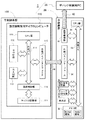
次に、デバッグシステム1における遊技機制御用マイクロコンピュータ110および中継装置30の詳細機能を説明する。図2は、遊技機制御用マイクロコンピュータ110および中継装置30の概略構成である。
Next, the detailed functions of the gaming
遊技機制御用マイクロコンピュータ110は、デバッグ作業に適した構造を備えるカスタムチップであり、出荷品に搭載する量産チップではないが、量産チップと同様、その内部には、少なくとも、CPU部111、ROM部112、RAM部113、内部バス114、外部バスインターフェース115、通信制御部116、チップID記憶部117を備えたワンチップ構造である。量産チップである通常の遊技機制御用マイクロコンピュータ110においては、CPU部111が、ROM部112に記憶されている遊技機制御用プログラムと参照用のデータに基づいて、ぱちんこ遊技を進行する制御を行う。また、RAM部113は、遊技進行に伴ってCPU部111が抽出した乱数値などの一時的な記憶情報を書き込むワークメモリとして用いられる。
The gaming
外部バスインターフェース115は、遊技機制御用マイクロコンピュータ110の外部と通信を行うためのインターフェースであり、主制御基板100に搭載されている各回路や他の制御基板等との送受信を可能にする。しかして、遊技機制御用マイクロコンピュータ100で用いる外部バスインターフェース115には、CPU部111が外部(後に詳述)へアクセス可能なアドレスを定義してあり、少なくとも、CPU部111がROM部112へアクセスするのと同様に、CPU部111がチップ外の該当アドレスから遊技機制御用プログラム等を読み出すことができる。
The
通信制御部116は、遊技機制御用マイクロコンピュータ110のセキュリティ管理を担うもので、適正な認証条件を満たした外部装置に対してのみ、チップID記憶部117に記憶されている当該遊技機制御用マイクロコンピュータ110に付されたチップIDや、ROM部112に記憶された遊技機制御用プログラム等の読み出しを可能にする。
The
一方、中継装置30は、少なくとも、CPU部31、メモリ部32、内部バス33、外部バスインターフェース34、通信制御部35、識別番号設定部36、グループID記憶部37、表示部38を備えている。中継装置30の通信制御部35は、ネットワーク40を介してデバッグ制御用PC20と接続され、デバッグ制御用PC20からの指令や遊技機制御用プログラム等を受信し、デバッグ制御用PC20から求められた収集データ(遊技機10の実射試験で収集されたデータ)を遊技機制御用マイクロコンピュータ110より取得してデバッグ制御用PC20へ送信する。また、デバッグ制御用PC20から供給される遊技機制御用プログラム等は、記憶手段としてのメモリ部32に記憶される。
On the other hand, the
中継装置30の外部バスインターフェース34は、遊技機制御用マイクロコンピュータ110の外部バスインターフェース115と対応したインターフェースを備え、コネクタ付ケーブル200を介して遊技機制御用マイクロコンピュータ110と接続される。しかして、遊技機制御用マイクロコンピュータ110の外部バスインターフェース115に定義されたアドレスは、中継装置30のメモリ部32のアドレスに対応させてある。したがって、遊技機制御用マイクロコンピュータ110のCPU部111は、内部バス114、外部バスインターフェース115、中継装置30の外部バスインターフェース34、内部バス33の経路で、メモリ部32に記憶されている遊技機制御用プログラム等を読み込むことが可能となる。
The
すなわち、バグ取りなどで更新した遊技機制御用プログラム等を中継装置30のメモリ部32に記憶させておけば、遊技機制御用マイクロコンピュータ110のCPU部111が、中継装置30のメモリ部32から更新した遊技機制御用プログラム等を読み出して実行するので、更新した遊技機制御用プログラム等を遊技機制御用マイクロコンピュータ110に実行させた遊技機10による実射試験を行うことが可能となる。よって、プログラム等を更新する度に、わざわざ主制御基板100から遊技機制御用マイクロコンピュータ110を取り外して、更新プログラムを書き込んだ別の遊技機制御用マイクロコンピュータ110を取り付ける作業が不要となり、非常に効率良くデバッグ作業を行うことができる。
That is, if the game machine control program and the like updated by removing bugs etc. are stored in the
また、中継装置30のCPU部31は、必要に応じて、外部バスインターフェース34が遊技機制御用マイクロコンピュータ110の外部バスインターフェース115に対してデータを出力するのを停止する(外部バスインターフェース34を遊技機制御用マイクロコンピュータ110に対して閉じる)ことができる。このように、中継装置30において、外部バスインターフェース34を遊技機制御用マイクロコンピュータ110に対して閉じると、遊技機制御用マイクロコンピュータ110のCPU部111は、中継装置30のメモリ部32から遊技機制御用プログラム等を読み出せなくなる。したがって、中継装置30のメモリ部32に格納した遊技機制御用プログラム等を遊技機制御用マイクロコンピュータ110のCPU部111が読み込むことを許可するか、読み込むことを許否するかを、中継装置30側でコントロールすることができる。
In addition, the
なお、遊技機制御用マイクロコンピュータ110内部のROM部112およびRAM部113と混同しないように、CPU部111から見た中継装置30内のメモリ部32のアドレスを、ROM部112およびRAM部113のアドレスとは異なるアドレスとして外部バスインターフェース115に定義しておく必要がある。また、メモリ部32にROM領域とRAM領域を分けてアドレスを定義しておき、メモリ部32のROM領域をROM部112に対応する遊技機制御用プログラム等の記憶領域に、メモリ部32のRAM領域をRAM部113に対応するワークメモリ領域に、夫々割り当てるようにしても良い。かくすれば、遊技機制御用マイクロコンピュータ110のCPU部111は、遊技進行に伴って抽出した乱数値などの一時的な記憶情報をメモリ部32に書き込んでゆくので、中継装置30は、これらの情報を遊技機制御用マイクロコンピュータ110のRAM部113からわざわざ読み込む必要がなく、自身のメモリ部32から直接読み込んでデバッグ制御用PC20へ送信できる。
The address of the
上述したデバッグシステム1において、更新した遊技機制御用プログラム等を遊技機制御用マイクロコンピュータ110のCPU部111に読み込ませるタイミングは特に限定されない。例えば、デバッグ制御用PC20から中継装置30に対して遊技機制御用プログラム等が送信され、これをメモリ部32に格納したタイミングで、遊技機制御用マイクロコンピュータ110のCPU部111に読み込ませるようにしても良いし、実射試験のデータ収集が所定条件を達成したタイミング(例えば、中継装置30が収集データをデバッグ制御用PC20へ送信したタイミング)で行わせるようにしても良い。
In the
また、更新した遊技機制御用プログラム等を遊技機制御用マイクロコンピュータ110のCPU部111に読み込ませるための手法も特に限定されるものではない。例えば、遊技機制御用マイクロコンピュータ110のリセット時に、中継装置30のメモリ部32のアドレスへジャンプするプログラムをROM部112に記憶させておき、遊技機制御用マイクロコンピュータ110のCPU部111に対してリセットをかければ、更新した遊技機制御用プログラム等を遊技機制御用マイクロコンピュータ110のCPU部111に読み込ませることができる。また、割込み処理としてメモリ部32のアドレスへジャンプするプログラムをROM部112に記憶させておき、中継装置30の外部バスインターフェース34から遊技機制御用マイクロコンピュータ110のCPU部111に対して割込み信号を送出することで、更新した遊技機制御用プログラム等を遊技機制御用マイクロコンピュータ110のCPU部111に読み込ませることができる。
Further, the method for causing the
ここで、遊技機制御用マイクロコンピュータ110のリセットによって、中継装置30のメモリ部32に格納した遊技機制御用プログラム等を遊技機制御用マイクロコンピュータ110のCPU部111に読み込ませて実行開始させる具体的手法について説明する。
Here, a specific method of causing the
遊技機制御用マイクロコンピュータ110のROM部112には、リセット時にCPU部111がROM部112からプログラムを読み出すべく設定されたアドレスがあり、ROM部112の該当アドレスには、メモリ部32の先頭アドレス(遊技機制御用プログラム等の開始行)へジャンプする命令を書き込んでおく。すなわち、CPU部111は、リセット時にROM部112から遊技機制御用プログラム等を読み出すことは無く、必ず、中継装置30のメモリ部32から遊技機制御用プログラム等を読み出すのである。このため、中継装置30が遊技機制御用マイクロコンピュータ110に接続されていないか、中継装置30の外部バスインターフェース34が遊技機制御用マイクロコンピュータ110の外部バスインターフェース115に対して閉じているときは、CPU部111がメモリ部32から遊技機制御用プログラム等の開始行を適正に読み込めず、中継装置30の非接続による不正命令を読み込むことになって、不正命令受信によるリセットがかかる。このリセットによって、CPU部111は再び中継装置30のメモリ部32を読み出そうとするが、読み出せずにリセットが繰り返され、遊技機制御用マイクロコンピュータ110が正常に起動することはない。
The
上記構造の遊技機制御用マイクロコンピュータ110を備える遊技機10において、遊技機制御用マイクロコンピュータ110が中継装置30のメモリ部32に格納された遊技機制御用プログラム等を実行して実射試験を行っているとき、中継装置30がデバッグ制御用PC20からのダウンロード開始コマンドを受信すると、まず、中継装置30のCPU部31が外部バスインターフェース34を遊技機制御用マイクロコンピュータ110の外部バスインターフェース115に対して閉じ、外部バスインターフェース34から遊技機制御用マイクロコンピュータ110に対してデータ出力するのを停止する。
In the gaming machine 10 provided with the gaming
これにより、遊技機制御用マイクロコンピュータ110のCPU部111は、中継装置30のメモリ部32から遊技機制御用プログラム等を読み出せなくなり、不正命令受信によるリセットが繰り返されるようになる。と同時に、遊技機制御用マイクロコンピュータ110のCPU部111からメモリ部32へのアクセスがなくなることで、メモリ部32の内容を書き換える準備が整う。
As a result, the
そして、遊技機制御用マイクロコンピュータ110が不正命令リセットのループを繰り返している間に、中継装置30は、デバッグ制御用PC20から新しい遊技機制御用プログラム等をダウンロードし、メモリ部32に格納する。ダウンロードが完了したら、中継装置30の外部バスインターフェース34を遊技機制御用マイクロコンピュータ110の外部バスインターフェース115に対して開く。これにより、遊技機制御用マイクロコンピュータ110のCPU部111は、中継装置30のメモリ部32から新しい遊技機制御用プログラム等を読み出せるようになるので、次にリセットがかかったタイミングで新しい遊技機制御用プログラム等を用いた実射試験が速やかに再開される。なお、中継装置30から遊技機制御用マイクロコンピュータ110をリセットする信号を用意しておき、新しい遊技機制御用プログラム等のダウンロードが完了したタイミングで、遊技機制御用マイクロコンピュータ110の主制御基板に対してリセットをかけるようにしても良い。
Then, while the gaming
次に、遊技機制御用マイクロコンピュータ110へ割込みをかけることによって、中継装置30のメモリ部32に格納した遊技機制御用プログラム等を遊技機制御用マイクロコンピュータ110のCPU部111に読み込ませて実行開始させる具体的手法について説明する。
Next, the gaming machine control program etc stored in the
遊技機制御用マイクロコンピュータ110のROM部112には、遊技機制御用プログラム等が書き込まれており、通常は、CPU部111がROM部112からプログラムを読み出して遊技機制御を行う。但し、ROM部112に書き込まれている遊技機制御プログラム等は、実射試験開始時に作成した古いプログラムである。また、ROM部112には、割込み信号を受けたときの割込み処理として中継装置30のメモリ部32の先頭アドレス(遊技機制御用プログラム等の開始行)へジャンプする命令を書き込んでおく。すなわち、CPU部111は、割込み信号を受信すると、この割り込み処理として、必ず、中継装置30のメモリ部32から遊技機制御用プログラム等を読み出すのである。
A game machine control program or the like is written in the
上記構造の遊技機制御用マイクロコンピュータ110において、CPU部111が中継装置30のメモリ部32に格納された遊技機制御用プログラム等を実行して実射試験を行っているとき、中継装置30がデバッグ制御用PC20からのダウンロード開始コマンドを受信すると、まず、中継装置30の外部バスインターフェース34から遊技機制御用マイクロコンピュータ110に対してデータ出力するのを停止する。
In the gaming
これにより、遊技機制御用マイクロコンピュータ110のCPU部111は、中継装置30のメモリ部32から遊技機制御用プログラム等を読み出せなくなり、不正命令受信によるリセットが生じ、CPU部111がROM部112から古いプログラムを読み出して遊技機制御を行うようになる。これと同時に、遊技機制御用マイクロコンピュータ110のCPU部111からメモリ部32へのアクセスがなくなることで、メモリ部32の内容を書き換える準備が整う。
As a result, the
そして、遊技機制御用マイクロコンピュータ110が古いプログラムで遊技制御を実行している間に、中継装置30は、デバッグ制御用PC20から新しい遊技機制御用プログラム等をダウンロードし、メモリ部32に格納する。ダウンロードが完了したら、中継装置30の外部バスインターフェース34を遊技機制御用マイクロコンピュータ110の外部バスインターフェース115に対して開く。そして、中継装置30から遊技機制御用マイクロコンピュータ110へ割込み信号を出力すると、CPU部111は中継装置30のメモリ部32から新しい遊技機制御用プログラム等を読み出して実行開始するので、新しい遊技機制御用プログラム等を用いた実射試験が速やかに再開される。
Then, while the gaming
なお、中継装置30のメモリ部32に格納された最新の遊技機制御用プログラム等を遊技機制御用マイクロコンピュータ110に実行させて実射試験を行っている間に、意図しないリセットが発生したとき、遊技機制御用マイクロコンピュータ110のCPU部111はROM部112から古いプログラムを読み出して再起動してしまうため、実射試験が中断されてしまう。そこで、CPU部111からリセット状態を示す信号(リセットモニタ信号)を出力させる構成としておき、リセットモニタ信号が外部バスインターフェース115を介して中継装置30へ入力されるようにすれば、CPU部111のリセット状態を検知した中継装置30が、速やかに遊技機制御用マイクロコンピュータ110へ割込み信号を出力することで、再び中継装置30のメモリ部32に格納された最新の遊技機制御用プログラム等を遊技機制御用マイクロコンピュータ110に実行させるように調整することが可能となる。
It should be noted that when an unexpected reset occurs while the game
上述したように、遊技機10の遊技機制御用マイクロコンピュータ110に新しい遊技機制御用プログラム等を実行させる機能を備えた中継装置30は、各遊技機10と1対1で接続されると共に、デバッグ制御用PC20と接続される。したがって、デバッグ制御用PC20から複数の中継装置30へ同時に遊技機制御用プログラム等の書き換えを指示することで、該当する中継装置30と接続された各遊技機10の遊技機制御用マイクロコンピュータ110に実行させる遊技機制御用プログラム等をまとめて更新することが可能となり、更なるデバッグ作業の効率化を期せる。
As described above, the
また、各中継装置30には識別番号設定部36を設けてあり、この識別番号設定部36によって自機の識別番号を設定することができる。この識別番号設定部36は、人為的操作によって任意の番号に設定できるものである。各中継装置30に対して設定された識別番号はデバッグ制御用PC20に送信され、デバッグ制御用PC20では、中継装置30の識別番号と、この中継装置30が接続されている遊技機10の固有情報(試作機の番号や機種など)とを紐付けて管理することで、各中継装置30へ送信する遊技機制御用プログラム等を適切に判断できる。なお、1台のデバッグ制御用PC20が管理している中継装置30の中に、識別番号が重複しているものがあれば、ウォーニング表示などで警告し、該当する中継装置30の識別番号設定部36による識別番号の再設定を作業者に促すようにしても良い。
Further, each
ただし、中継装置30に設定した識別番号は、中継装置30の電源を落としたり、リセットされたりした後にも、同じ設定値として継続利用できる必要がある。かくするために、例えば、中継装置30に設ける識別番号設定部37は、設定内容を保持できるロータリースイッチやディップスイッチ等で構成し、中継装置30の起動時に識別番号設定部37の設定内容を読み込むことで自機の識別番号を特定できるようにしても良いし、入力された識別番号を不揮発性のメモリ、或いは電池や蓄電コンデンサ等でバックアップされたメモリに記憶しておくようにしても良い。
However, the identification number set in the
前述したように、デバッグ制御用PC20は、複数の遊技機10を一括りのグループとして管理することで、効率良くデバッグ作業を行うことが可能となる。そこで、各遊技機10に1対1で接続されている中継装置30に設定された識別番号を用いて、デバッグ制御用PC20によるグループ管理を行うものとする。
As described above, the
例えば、同一機種の試作機である複数台の遊技機10に対応する中継装置30の識別番号を選定して、一つのグループを形成する。グループ管理を行うことができれば、プログラム更新対象の中継装置30を逐一指定しなくても、グループを指定して遊技機制御用プログラム等の送信を一斉に行うことが可能となる。実射試験においては、全ての遊技機が同一機種の場合だけでなく、異なる複数の機種を同時に試験したり、同一の機種であっても大当り確率の異なるバージョンを同時に試験したりする場合があるので、同じ遊技機制御用プログラムを適用できる遊技機群をグループとして括り、遊技機制御用プログラム等の更新操作を行うときには、該当するグループを操作対象とすることで、遊技機制御用プログラム等の更新操作を簡便にすると共に、操作ミスを低減させることができる。
For example, identification numbers of
グループ管理を可能にするために、デバッグ制御用PC20は、グループ識別情報としてのグループIDを各グループに設定し、該当するグループの各中継装置30に対して自機が属するグループのグループIDを送信する。なお、グループIDは数値であってもよいし、数値と記号の組合せであってもよい。そして、デバッグ制御用PC20からグループIDを受信した中継装置30は、グループ識別情報記憶手段としてのグループID記憶部37にグループIDを記憶し、記憶したグループIDに対応した表示を表示部38に対して行う。なお、グループID記憶部37の機能は、メモリ部32によって実現するようにしても構わない。
To enable group management, the
表示部38は、グループIDに対応した表示を行うことができれば、どのような表示機能のものでも構わない。例えば、数桁の番号数値からなるグループIDをそのまま表示する場合には、数桁のセグメント表示器でも良いし、低画素の液晶表示器を用いることもできる。また、グループIDを特定の色彩に対応させておく場合には、それらの色彩表示を行える多色発光パネルやカラー液晶表示パネル等を表示部38として用いることができる。なお、グループIDを色彩に対応させる場合、各グループIDに対応させた色彩が視認困難な類似色とならないように注意しておく必要がある。
The
このように、各中継装置30に設けた表示部38によってグループIDを確認することができれば、デバッグ制御用PC20で設定したグループ割り当てを、各遊技機10に接続された中継装置30の表示部38で実際に確認できるので、異なる機種が同一のグループに含まれるような作業ミスを効率的に回避できるという利点がある。特に、実射試験に供される遊技機10とデバッグ制御用PC20とが別の部屋にあったり、同一の部屋にあっても少し離れていたりして、各遊技機10の外観とデバッグ制御用PC20のグループ設定画面とを同時に目視することができない場合、各遊技機10の外観と各中継装置30における表示部38のグループ表示とからグループ分けの適否を確認できるメリットは非常に大きい。
As described above, if the group ID can be confirmed by the
以上、本発明に係るデバッグシステムの実施形態を添付図面に基づいて説明したが、本発明は、この実施形態に限定されるものではなく、特許請求の範囲に記載の構成を変更しない範囲で、公知既存の等価な技術手段を転用することにより実施しても構わない。 As mentioned above, although the embodiment of the debugging system concerning the present invention was described based on an accompanying drawing, the present invention is not limited to this embodiment, In the range which does not change the composition as described in a claim, You may implement by diverting the well-known existing equivalent technical means.
1 デバッグシステム
10 遊技機
100 主制御基板
110 遊技機制御用マイクロコンピュータ
111 CPU部
112 ROM部
113 RAM部
115 外部バスインターフェース
200 コネクタ付ケーブル
20 デバッグ制御用PC
30 中継装置
32 メモリ部
34 外部バスインターフェース
35 通信制御部
40 ネットワーク
DESCRIPTION OF
30
Claims (7)
前記中継装置は、少なくとも、前記デバッグ装置から供給される遊技機制御用のプログラムやデータを記憶する記憶手段と、前記遊技機制御用マイクロコンピュータの外部バスインターフェースに対応した外部バスインターフェースと、を備え、
前記遊技機制御用マイクロコンピュータは、少なくとも、遊技機制御用のプログラムやデータを読み出して実行するCPU部と、該CPU部が前記中継装置の記憶手段へアクセス可能なアドレスが定義された外部バスインターフェースと、を備え、
前記デバッグ装置から中継装置の記憶手段に記憶された遊技機制御用のプログラムやデータを、遊技機制御用マイクロコンピュータのCPU部が読み出して実行することにより、遊技機制御用のプログラムやデータを更新できるようにしたことを特徴とするデバッグシステム。 A microcomputer for gaming machine control provided on a main control board for main control of a gaming machine, and a debugging operation for removing a bug included in a program or data used for the gaming machine control microcomputer to perform gaming machine control A debugging system comprising: a debugging device; and a relay device connected between the gaming machine control microcomputer and the debugging device,
The relay device comprises at least storage means for storing a program or data for controlling a gaming machine supplied from the debugging device, and an external bus interface corresponding to an external bus interface of the microcomputer for controlling a gaming machine.
The gaming machine control microcomputer has at least a CPU unit that reads and executes a program or data for gaming machine control, and an external bus interface in which an address at which the CPU unit can access the storage unit of the relay device is defined. Equipped with
The program and data for controlling the gaming machine can be updated by the CPU unit of the microcomputer for controlling the gaming machine reading and executing the program and data for controlling the gaming machine stored in the storage means of the relay device from the debugging device. A debugging system characterized by having done.
前記デバッグ装置は、複数の中継装置と接続可能とし、
前記デバッグ装置から複数の中継装置へ遊技機制御用のプログラムやデータを書き込むことで、該当する中継装置と接続された各遊技機の遊技機制御用マイクロコンピュータに実行させる遊技機制御用のプログラムやデータをまとめて更新するようにしたことを特徴とする請求項1〜請求項3の何れか1項に記載のデバッグシステム。 The relay device is connected to the gaming machine control microcomputer in one gaming machine on a one-to-one basis.
The debugging device can be connected to a plurality of relay devices,
The program and data for game machine control to be executed on the game machine control microcomputer of each game machine connected to the corresponding relay device are put together by writing the program and data for game machine control from the debugging device to a plurality of relay devices. The debugging system according to any one of claims 1 to 3, wherein the system is updated.
前記デバッグ装置は、各中継装置の識別番号設定手段に設定されている識別番号によって、当該中継装置が接続されている遊技機を識別するようにしたことを特徴とする請求項4に記載のデバッグシステム。 The relay device is provided with identification number setting means capable of setting the identification number of the own device.
5. The debugging according to claim 4, wherein the debugging device identifies the gaming machine to which the relay device is connected by the identification number set in the identification number setting means of each relay device. system.
前記デバッグ装置よりグループ識別情報を受信した中継装置は、受信したグループ識別情報をグループ識別情報記憶手段に記憶するようにしたことを特徴とする請求項5に記載のデバッグシステム。 The debugging device sets group identification information by bundling one or more gaming machines, and transmits the group identification information to a relay device corresponding to each gaming machine of the group.
6. The debugging system according to claim 5, wherein the relay device receiving the group identification information from the debugging device stores the received group identification information in the group identification information storage means.
Priority Applications (1)
| Application Number | Priority Date | Filing Date | Title |
|---|---|---|---|
| JP2017076556A JP6879505B2 (en) | 2017-04-07 | 2017-04-07 | Debug system |
Applications Claiming Priority (1)
| Application Number | Priority Date | Filing Date | Title |
|---|---|---|---|
| JP2017076556A JP6879505B2 (en) | 2017-04-07 | 2017-04-07 | Debug system |
Publications (2)
| Publication Number | Publication Date |
|---|---|
| JP2018175149A true JP2018175149A (en) | 2018-11-15 |
| JP6879505B2 JP6879505B2 (en) | 2021-06-02 |
Family
ID=64280080
Family Applications (1)
| Application Number | Title | Priority Date | Filing Date |
|---|---|---|---|
| JP2017076556A Active JP6879505B2 (en) | 2017-04-07 | 2017-04-07 | Debug system |
Country Status (1)
| Country | Link |
|---|---|
| JP (1) | JP6879505B2 (en) |
Cited By (4)
| Publication number | Priority date | Publication date | Assignee | Title |
|---|---|---|---|---|
| JP2021074135A (en) * | 2019-11-07 | 2021-05-20 | 株式会社ユニバーサルエンターテインメント | Game machine |
| JP2021074130A (en) * | 2019-11-07 | 2021-05-20 | 株式会社ユニバーサルエンターテインメント | Game machine |
| JP2021074129A (en) * | 2019-11-07 | 2021-05-20 | 株式会社ユニバーサルエンターテインメント | Game machine |
| JP2021074134A (en) * | 2019-11-07 | 2021-05-20 | 株式会社ユニバーサルエンターテインメント | Game machine |
-
2017
- 2017-04-07 JP JP2017076556A patent/JP6879505B2/en active Active
Cited By (8)
| Publication number | Priority date | Publication date | Assignee | Title |
|---|---|---|---|---|
| JP2021074135A (en) * | 2019-11-07 | 2021-05-20 | 株式会社ユニバーサルエンターテインメント | Game machine |
| JP2021074130A (en) * | 2019-11-07 | 2021-05-20 | 株式会社ユニバーサルエンターテインメント | Game machine |
| JP2021074129A (en) * | 2019-11-07 | 2021-05-20 | 株式会社ユニバーサルエンターテインメント | Game machine |
| JP2021074134A (en) * | 2019-11-07 | 2021-05-20 | 株式会社ユニバーサルエンターテインメント | Game machine |
| JP7217957B2 (en) | 2019-11-07 | 2023-02-06 | 株式会社ユニバーサルエンターテインメント | game machine |
| JP7217952B2 (en) | 2019-11-07 | 2023-02-06 | 株式会社ユニバーサルエンターテインメント | game machine |
| JP7217951B2 (en) | 2019-11-07 | 2023-02-06 | 株式会社ユニバーサルエンターテインメント | game machine |
| JP7217956B2 (en) | 2019-11-07 | 2023-02-06 | 株式会社ユニバーサルエンターテインメント | game machine |
Also Published As
| Publication number | Publication date |
|---|---|
| JP6879505B2 (en) | 2021-06-02 |
Similar Documents
| Publication | Publication Date | Title |
|---|---|---|
| JP2018175149A (en) | Debugging system | |
| JP2010207478A5 (en) | ||
| JP6879500B2 (en) | Microcomputer for game machine control | |
| JP4724961B2 (en) | Game machine | |
| JP6879506B2 (en) | Debug system | |
| JP5652893B2 (en) | Pachinko machine | |
| JP2012231906A5 (en) | Game machines and game slots | |
| JP2014213035A (en) | Pachinko game machine | |
| JP5652894B2 (en) | Pachinko machine | |
| JP5380656B2 (en) | Game system | |
| JP4747458B2 (en) | Game machine | |
| JP2011078650A5 (en) | ||
| JP4747459B2 (en) | Game machine | |
| JP2011056279A (en) | Controller of game machine | |
| JP2017108890A (en) | Game machine conversion device and diverted game machine | |
| JP2016140383A (en) | Game machine | |
| JP2015027584A (en) | Pachinko game machine | |
| JP2006288707A (en) | Game machine | |
| JP2010227619A (en) | Game machine | |
| JP5825366B2 (en) | Game machine | |
| JP2012228579A (en) | Control device of game machine | |
| JP4656253B2 (en) | Game machine | |
| JP6052903B2 (en) | Pachinko machine | |
| JP6052904B2 (en) | Pachinko machine | |
| JP4645702B2 (en) | Game machine |
Legal Events
| Date | Code | Title | Description |
|---|---|---|---|
| A621 | Written request for application examination |
Free format text: JAPANESE INTERMEDIATE CODE: A621 Effective date: 20191101 |
|
| A131 | Notification of reasons for refusal |
Free format text: JAPANESE INTERMEDIATE CODE: A131 Effective date: 20200818 |
|
| A977 | Report on retrieval |
Free format text: JAPANESE INTERMEDIATE CODE: A971007 Effective date: 20200814 |
|
| A521 | Written amendment |
Free format text: JAPANESE INTERMEDIATE CODE: A523 Effective date: 20201016 |
|
| TRDD | Decision of grant or rejection written | ||
| A01 | Written decision to grant a patent or to grant a registration (utility model) |
Free format text: JAPANESE INTERMEDIATE CODE: A01 Effective date: 20210330 |
|
| A61 | First payment of annual fees (during grant procedure) |
Free format text: JAPANESE INTERMEDIATE CODE: A61 Effective date: 20210421 |
|
| R150 | Certificate of patent or registration of utility model |
Ref document number: 6879505 Country of ref document: JP Free format text: JAPANESE INTERMEDIATE CODE: R150 |