JP2018166375A - Power system - Google Patents
Power system Download PDFInfo
- Publication number
- JP2018166375A JP2018166375A JP2017063348A JP2017063348A JP2018166375A JP 2018166375 A JP2018166375 A JP 2018166375A JP 2017063348 A JP2017063348 A JP 2017063348A JP 2017063348 A JP2017063348 A JP 2017063348A JP 2018166375 A JP2018166375 A JP 2018166375A
- Authority
- JP
- Japan
- Prior art keywords
- battery
- metal hydride
- load
- nickel metal
- power supply
- Prior art date
- Legal status (The legal status is an assumption and is not a legal conclusion. Google has not performed a legal analysis and makes no representation as to the accuracy of the status listed.)
- Pending
Links
Images

Landscapes
- Charge And Discharge Circuits For Batteries Or The Like (AREA)
Abstract
【課題】車両用の電源システムにおいて、バッテリの放電時に生じ得る各種不具合の発生を抑制しつつ、バッテリの放電機会を多く得ることができるようにすること。【解決手段】電源システムは、第1のバッテリと、前記第1のバッテリから供給された電力により動作する負荷と、第2のバッテリと、前記第2のバッテリと前記負荷との間に接続されたスイッチと、前記第2のバッテリの充電容量が所定値以上であり、且つ、前記第1のバッテリの電圧が所定値未満であり、且つ、車両がアイドリング走行中ではなく、且つ、前記第1のバッテリと前記第2のバッテリとの電位差が所定値以上である場合に、前記スイッチをONすることにより、前記第2のバッテリの放電を行う制御装置とを備える。【選択図】図1In a power supply system for a vehicle, it is possible to obtain many opportunities for discharging a battery while suppressing the occurrence of various problems that may occur when the battery is discharged. A power supply system is connected between a first battery, a load that operates with electric power supplied from the first battery, a second battery, and the second battery and the load. And the charge capacity of the second battery is greater than or equal to a predetermined value, the voltage of the first battery is less than a predetermined value, the vehicle is not idling, and the first battery A control device that discharges the second battery by turning on the switch when the potential difference between the second battery and the second battery is equal to or greater than a predetermined value. [Selection] Figure 1
Description
本発明は、電源システムに関する。 The present invention relates to a power supply system.
従来より、車両用の電源システムにおいて、複数のバッテリを複数の負荷に接続することで、複数のバッテリから供給された電力により、複数の負荷を動作させることができるようにした技術が知られている。 2. Description of the Related Art Conventionally, in a power supply system for a vehicle, a technology has been known in which a plurality of loads can be operated by electric power supplied from the plurality of batteries by connecting the plurality of batteries to a plurality of loads. Yes.
例えば、下記特許文献1には、車両に搭載される電源装置において、第1のバッテリおよび第2のバッテリを複数の負荷に接続可能に構成し、高負荷機器(例えば、電動アクティブスタビライザ)が作動しているときには、高負荷機器に対し、第1のバッテリおよび第2のバッテリの両方から電力を供給することにより、車両電源電圧の低下を防止し、高負荷機器が作動していない場合には、第2のバッテリを、複数の負荷機器から電気的に切断することにより、第2のバッテリの充放電に起因する劣化を防止することができるようにした技術が開示されている。 For example, in Patent Document 1 below, in a power supply device mounted on a vehicle, a first battery and a second battery are configured to be connectable to a plurality of loads, and a high-load device (for example, an electric active stabilizer) operates. When power is supplied to the high load device from both the first battery and the second battery, the vehicle power supply voltage is prevented from decreasing, and the high load device is not operating. A technique has been disclosed in which the second battery is electrically disconnected from a plurality of load devices, thereby preventing deterioration due to charging / discharging of the second battery.
しかしながら、上記特許文献1に開示されている技術では、高負荷機器が作動していない状態が続いた場合には、第2のバッテリが放電されない状態が続くため、特に、第2のバッテリが過充電状態にある場合には、第2のバッテリが劣化してしまう虞がある。また、上記特許文献1に開示されている技術では、第2のバッテリを放電するときに、第2のバッテリが第1のバッテリにも接続されるため、第1のバッテリからの電力によって第2のバッテリがさらに過充電されてしまったり、この過充電を防止するために、直ちにスイッチをOFFする等により、スイッチの切り換えが頻繁に発生してしまったりする等の不具合が発生する虞がある。 However, in the technique disclosed in Patent Document 1, when the state in which the high load device is not operated continues, the state in which the second battery is not discharged continues. When the battery is in the charged state, the second battery may be deteriorated. Further, in the technique disclosed in Patent Literature 1, when the second battery is discharged, the second battery is also connected to the first battery, so that the second battery is powered by the power from the first battery. The battery may be overcharged further, or in order to prevent this overcharge, there is a possibility that problems such as frequent switching of the switch may occur due to immediately turning off the switch.
本発明は、上述した従来技術の課題を解決するため、車両用の電源システムにおいて、バッテリの放電時に生じ得る各種不具合の発生を抑制しつつ、バッテリの放電機会を多く得ることができるようにすることを目的とする。 In order to solve the above-described problems of the related art, the present invention enables a vehicle power supply system to obtain many opportunities for battery discharge while suppressing the occurrence of various problems that may occur during battery discharge. For the purpose.
本発明の実施形態の電源システムは、第1のバッテリと、前記第1のバッテリから供給された電力により動作する負荷と、第2のバッテリと、前記第2のバッテリと前記負荷との間に接続されたスイッチと、前記第2のバッテリの充電容量が所定値以上であり、且つ、前記第1のバッテリの電圧が所定値未満であり、且つ、前記車両がアイドリング走行中ではなく、且つ、前記第1のバッテリと前記第2のバッテリとの電位差が所定値以上である場合に、前記スイッチをONすることにより、前記第2のバッテリの放電を行う制御装置とを備える。 A power supply system according to an embodiment of the present invention includes a first battery, a load that operates by power supplied from the first battery, a second battery, and the second battery and the load. A charge capacity of the connected switch and the second battery is equal to or greater than a predetermined value, a voltage of the first battery is less than a predetermined value, and the vehicle is not idling, and A controller that discharges the second battery by turning on the switch when a potential difference between the first battery and the second battery is equal to or greater than a predetermined value;
車両用の電源システムにおいて、バッテリの放電時に生じ得る各種不具合の発生を抑制しつつ、バッテリの放電機会を多く得ることができる。 In a vehicle power supply system, it is possible to obtain many battery discharge opportunities while suppressing the occurrence of various problems that may occur during battery discharge.
以下、図面を参照して、本発明の実施形態の電源システムについて説明する。 Hereinafter, a power supply system according to an embodiment of the present invention will be described with reference to the drawings.
(電源システム10の構成)
図1は、実施形態に係る電源システム10のシステム構成を示す図である。図1に示す電源システム10は、自動車等の車両に搭載されており、車両の各部に電力を供給するためのシステムである。特に、電源システム10は、アイドリングストップ機能を有する車両に搭載されるシステムである。
(Configuration of power supply system 10)
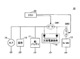
FIG. 1 is a diagram illustrating a system configuration of a
図1に示すように、電源システム10は、鉛バッテリ11、ニッケル水素電池12、負荷13、冗長電源負荷14、オルタネータ15、ECU(Electronic Control Unit)20、スイッチSW1、およびスイッチSW2を備えて構成されている。
As shown in FIG. 1, the
鉛バッテリ11は、「第1のバッテリ」の一例である。鉛バッテリ11は、負荷13および冗長電源負荷14に接続されている。これにより、鉛バッテリ11は、負荷13および冗長電源負荷14に電力を供給する。
The lead battery 11 is an example of a “first battery”. The lead battery 11 is connected to a
ニッケル水素電池12は、「第2のバッテリ」の一例である。ニッケル水素電池12は、スイッチSW2を介して、冗長電源負荷14に接続されている。これにより、ニッケル水素電池12は、例えば、鉛バッテリ11から冗長電源負荷14への電力が断たれたとき(例えば、鉛バッテリ11が故障したとき、イグニッションがOFFになったとき等)に、スイッチSW2がONになることで、冗長電源負荷14に電力を供給するための、バックアップ電源として機能する。また、ニッケル水素電池12は、スイッチSW1,SW2を介して、負荷13にも接続されている。これにより、ニッケル水素電池12は、スイッチSW1,SW2の双方がONになることで、負荷13にも電力を供給することが可能となっている。
The nickel
負荷13は、鉛バッテリ11に接続されている。負荷13は、鉛バッテリ11から供給される電力によって動作可能な電気機器である。負荷13としては、例えば、スタータモータ等が挙げられる。
The
冗長電源負荷14は、鉛バッテリ11およびニッケル水素電池12の双方に接続されている。冗長電源負荷14は、鉛バッテリ11から供給される電力と、ニッケル水素電池12から供給される電力との双方によって動作可能な電子機器である。例えば、冗長電源負荷14は、鉛バッテリ11からの電力の供給が断たれたときも、バックアップ電源として機能するニッケル水素電池12から供給される電力によって動作可能である。冗長電源負荷14としては、例えば、ナビゲーション装置等が挙げられる。
The
オルタネータ15は、発電装置である。オルタネータ15から出力された電力は、例えば、負荷13および冗長電源負荷14に供給され、負荷13および冗長電源負荷14の動作に用いられる。また、オルタネータ15から出力された電力は、鉛バッテリ11およびニッケル水素電池12に供給され、鉛バッテリ11およびニッケル水素電池12の充電に用いられる。
The
スイッチSW1,SW2は、ニッケル水素電池12と鉛バッテリ11との間に、直列に設けられている。具体的には、スイッチSW1は、冗長電源負荷14の鉛バッテリ11側の端子と、冗長電源負荷14のニッケル水素電池12側の端子との間に設けられている。また、スイッチSW2は、冗長電源負荷14のニッケル水素電池12側の端子と、ニッケル水素電池12との間に設けられている。スイッチSW1は、ECU20の制御によってONおよびOFFに切り替えられることにより、ニッケル水素電池12から鉛バッテリ11に至る電力供給路を、接続状態と切断状態との間で切り替える。スイッチSW2は、ECU20の制御によってONおよびOFFに切り替えられることにより、ニッケル水素電池12と冗長電源負荷14との間の電力供給路を、接続状態と切断状態との間で切り替える。
The switches SW1 and SW2 are provided in series between the nickel
ECU20は、「制御装置」の一例である。ECU20は、スイッチSW1,SW2の状態を制御することにより、ニッケル水素電池12の放電を制御する。具体的には、ECU20は、下記4つの条件を全て満たすとき、スイッチSW1,SW2の双方をONにする。これにより、ECU20は、ニッケル水素電池12の電力が負荷13に供給されるようにして、ニッケル水素電池12から電力を放電させる。
The
・条件1:ニッケル水素電池12の充電容量が所定の閾値以上である。
Condition 1: The charge capacity of the nickel
・条件2:鉛バッテリ11の電圧が所定の閾値未満である。 Condition 2: The voltage of the lead battery 11 is less than a predetermined threshold value.
・条件3:車両がアイドリング走行中ではない。 -Condition 3: The vehicle is not idling.
・条件4:鉛バッテリ11とニッケル水素電池12との電位差が所定値以上である。
Condition 4: The potential difference between the lead battery 11 and the nickel
条件1に関し、例えば、ECU20は、ニッケル水素電池12に接続された電圧センサから、ニッケル水素電池12の電圧値を取得する。そして、例えば、ECU20は、取得した電圧値を用いて、所定の演算式による演算を行うことにより、ニッケル水素電池12の充電容量を算出することができる。または、例えば、ECU20は、電圧値と充電容量との対応付けが予めなされている対応テーブルを参照することにより、取得した電圧値に対応するニッケル水素電池12の充電容量を導出することができる。
Regarding the condition 1, for example, the
条件2に関し、例えば、ECU20は、鉛バッテリ11に接続された電圧センサから、鉛バッテリ11の電圧を取得することができる。
Regarding the condition 2, for example, the
条件3に関し、例えば、ECU20は、車両のエンジンを制御するエンジンECUから出力された各種制御情報(例えば、エンジン回転数、車速、アクセル開度等)に基づいて、アイドリング走行中であるか否かを判断することができる。例えば、ECU20は、エンジン回転数が所定値以下のとき、車速が所定値以下のとき、アクセル開度が所定値以下のとき、の少なくともいずれか一つの条件が満たされたとき、アイドリング走行中であると判断してもよい。
Regarding the condition 3, for example, the
条件4に関し、例えば、ECU20は、鉛バッテリ11に接続された電圧センサから取得した鉛バッテリ11の電圧値と、ニッケル水素電池12に接続された電圧センサから取得したニッケル水素電池12の電圧値とに基づいて、鉛バッテリ11とニッケル水素電池12との電位差を算出することができる。
Regarding the condition 4, for example, the
なお、ECU20は、次のように、ニッケル水素電池12の放電を制御することもできる。
The
例えば、ECU20は、負荷13が必要とする電力が、所定値以上の場合(鉛バッテリ11からの電力のみでは不足する場合)には、スイッチSW1,SW2の双方をONにすることにより、鉛バッテリ11およびニッケル水素電池12の各々から、負荷13へ電力が供給されるようにすることができる。
For example, when the electric power required by the
一方、ECU20は、負荷13が必要とする電力が、所定値未満の場合(鉛バッテリ11からの電力のみで十分な場合)には、スイッチSW1をOFFすることにより、ニッケル水素電池12から、負荷13へ電力が供給されないようにすることができる。
On the other hand, when the electric power required by the
また、例えば、ECU20は、ニッケル水素電池12の過放電時や過充電時、または、ニッケル水素電池12が劣化した場合に、スイッチSW2をOFFすることにより、ニッケル水素電池12を保護することができる。
For example, the
また、例えば、ECU20は、鉛バッテリ11から冗長電源負荷14への電源が断たれたとき、スイッチSW2をONするとともに、スイッチSW1をOFFすることにより、ニッケル水素電池12を冗長電源負荷14のバックアップ電源として機能させることができる。
Further, for example, when the power supply from the lead battery 11 to the
ECU20は、例えば、プロセッサ、記憶装置等のハードウェアを備えて構成されている。ECU20は、記憶装置に記憶されているプログラムをプロセッサが実行することにより、上記したECU20の各機能を実現する。なお、プロセッサとしては、例えば、CPU(Central Processing Unit)、MPU(Micro Processing Unit)等が挙げられる。また、記憶装置としては、例えば、ROM(Read Only Memory)、RAM等が挙げられる。
The
(ECU20による処理の手順)
図2は、実施形態に係るECU20による処理の手順を示すフローチャートである。なお、以下の説明において、スイッチSW2はONになっているものとする。
(Processing procedure by ECU 20)
FIG. 2 is a flowchart illustrating a processing procedure performed by the
まず、ECU20は、ニッケル水素電池12の充電容量が所定の閾値以上であるか否かを判断する(ステップS201)。ステップS201において、ニッケル水素電池12の充電容量が所定の閾値以上ではないと判断された場合(ステップS201:No)、ECU20は、スイッチSW1をOFFにして(ステップS205)、図2に示す一連の処理を終了する。
First, the
一方、ステップS201において、ニッケル水素電池12の充電容量が所定の閾値以上であると判断された場合(ステップS201:Yes)、ECU20は、鉛バッテリ11の電圧が所定の閾値未満であるか否を判断する(ステップS202)。ステップS202において、鉛バッテリ11の電圧が所定の閾値未満ではないと判断された場合(ステップS202:No)、ECU20は、スイッチSW1をOFFにして(ステップS205)、図2に示す一連の処理を終了する。
On the other hand, when it is determined in step S201 that the charge capacity of the nickel
一方、ステップS202において、鉛バッテリ11の電圧が所定の閾値未満であると判断された場合(ステップS202:Yes)、ECU20は、車両がアイドリング走行中であるか否かを判断する(ステップS203)。ステップS203において、車両がアイドリング走行中であると判断された場合(ステップS203:Yes)、ECU20は、スイッチSW1をOFFにして(ステップS205)、図2に示す一連の処理を終了する。
On the other hand, when it is determined in step S202 that the voltage of the lead battery 11 is less than the predetermined threshold (step S202: Yes), the
一方、ステップS203において、車両がアイドリング走行中ではないと判断された場合、(ステップS203:No)、ECU20は、鉛バッテリ11とニッケル水素電池12との間に所定値以上の電位差があるか否かを判断する(ステップS204)。ステップS204において、所定値以上の電位差がないと判断された場合(ステップS204:No)、ECU20は、スイッチSW1をOFFにして(ステップS205)、図2に示す一連の処理を終了する。
On the other hand, if it is determined in step S203 that the vehicle is not idling (step S203: No), the
一方、ステップS204において、所定値以上の電位差があると判断された場合(ステップS204:Yes)、ECU20は、スイッチSW1をONにして(ステップS206)、図2に示す一連の処理を終了する。
On the other hand, when it is determined in step S204 that there is a potential difference equal to or greater than a predetermined value (step S204: Yes), the
以上説明したように、本実施形態に係る電源システム10によれば、ニッケル水素電池12の充電容量が所定の閾値以上であり、且つ、鉛バッテリ11の電圧が所定の閾値未満である場合には、ニッケル水素電池12の放電を行うことで、ニッケル水素電池12の放電機会を増やすことができる。
As described above, according to the
特に、本実施形態に係る電源システム10によれば、鉛バッテリ11の電圧が所定の閾値以上である場合には、ニッケル水素電池12の放電を行わないため、鉛バッテリ11の電力によってニッケル水素電池12が過充電されてしまうといった不具合の発生を抑制することができる。
In particular, according to the
また、本実施形態に係る電源システム10は、車両がアイドリング走行中のときは、ニッケル水素電池12の放電を行わないようにしている。例えば、車両がアイドリングストップ状態のとき、ニッケル水素電池12の放電を防止するために、スイッチSW1はOFFに制御される。そして、車両がアイドリング走行を開始したときに、例えば、スイッチSW1をONにして、ニッケル水素電池12の放電を行ったとしても、ニッケル水素電池12の過充電保護機能が働き、すぐにスイッチSW1がOFFに切り替わってしまい、スイッチSW1の無駄なリレー制御が発生してしまうこととなる。そこで、本実施形態に係る電源システム10は、車両がアイドリング走行中のときは、ニッケル水素電池12の放電を行わないようにすることで、このようなスイッチSW1の無駄なリレー制御の発生を抑制することができる。
Further, the
さらに、本実施形態に係る電源システム10は、鉛バッテリ11とニッケル水素電池12と電位差が所定値以上ではないときは、ニッケル水素電池12の放電を行わないようにしている。例えば、鉛バッテリ11とニッケル水素電池12と電位差が少ない時に、ニッケル水素電池12の放電を行うと、ニッケル水素電池12が微量に充電される場合がある。このような充電が蓄積されると、ニッケル水素電池12の充電容量が上限値に張り付いてしまう等の、ニッケル水素電池12の機能損失が生じる虞がある。そこで、本実施形態に係る電源システム10は、鉛バッテリ11とニッケル水素電池12と電位差が所定値以上ではないときは、ニッケル水素電池12の放電を行わないようにすることで、このようなニッケル水素電池12の機能損失の発生を抑制することができる。
Furthermore, the
以上、本発明の好ましい実施形態について詳述したが、本発明はこれらの実施形態に限定されるものではなく、特許請求の範囲に記載された本発明の要旨の範囲内において、種々の変形又は変更が可能である。 The preferred embodiments of the present invention have been described in detail above. However, the present invention is not limited to these embodiments, and various modifications or changes can be made within the scope of the gist of the present invention described in the claims. It can be changed.
なお、「第1のバッテリ」は、鉛バッテリに限らず、それ以外のバッテリ(例えば、リチウムイオン電池、ニッケル水素電池等)であってもよい。また、「第2のバッテリ」は、ニッケル水素電池に限らず、それ以外のバッテリ(例えば、リチウムイオン電池、鉛バッテリ等)であってもよい。 The “first battery” is not limited to a lead battery, but may be other batteries (for example, a lithium ion battery, a nickel metal hydride battery, etc.). Further, the “second battery” is not limited to a nickel metal hydride battery, but may be other batteries (for example, a lithium ion battery, a lead battery, etc.).
10 電源システム
11 鉛バッテリ(第1のバッテリ)
12 ニッケル水素電池(第2のバッテリ)
13 負荷
14 冗長電源負荷
15 オルタネータ
20 ECU(制御装置)
SW1 スイッチ
SW2 スイッチ
10 Power supply system 11 Lead battery (first battery)
12 Nickel metal hydride battery (second battery)
13
SW1 switch SW2 switch
Claims (1)
前記第1のバッテリから供給された電力により動作する負荷と、
第2のバッテリと、
前記第2のバッテリと前記負荷との間に接続されたスイッチと、
前記第2のバッテリの充電容量が所定値以上であり、且つ、前記第1のバッテリの電圧が所定値未満であり、且つ、車両がアイドリング走行中ではなく、且つ、前記第1のバッテリと前記第2のバッテリとの電位差が所定値以上である場合に、前記スイッチをONすることにより、前記第2のバッテリの放電を行う制御装置と
を備える電源システム A first battery;
A load that operates with electric power supplied from the first battery;
A second battery;
A switch connected between the second battery and the load;
The charge capacity of the second battery is greater than or equal to a predetermined value, the voltage of the first battery is less than a predetermined value, the vehicle is not idling, and the first battery and the A power supply system comprising: a control device that discharges the second battery by turning on the switch when a potential difference from the second battery is equal to or greater than a predetermined value.
Priority Applications (1)
| Application Number | Priority Date | Filing Date | Title |
|---|---|---|---|
| JP2017063348A JP2018166375A (en) | 2017-03-28 | 2017-03-28 | Power system |
Applications Claiming Priority (1)
| Application Number | Priority Date | Filing Date | Title |
|---|---|---|---|
| JP2017063348A JP2018166375A (en) | 2017-03-28 | 2017-03-28 | Power system |
Publications (1)
| Publication Number | Publication Date |
|---|---|
| JP2018166375A true JP2018166375A (en) | 2018-10-25 |
Family
ID=63922861
Family Applications (1)
| Application Number | Title | Priority Date | Filing Date |
|---|---|---|---|
| JP2017063348A Pending JP2018166375A (en) | 2017-03-28 | 2017-03-28 | Power system |
Country Status (1)
| Country | Link |
|---|---|
| JP (1) | JP2018166375A (en) |
-
2017
- 2017-03-28 JP JP2017063348A patent/JP2018166375A/en active Pending
Similar Documents
| Publication | Publication Date | Title |
|---|---|---|
| CN105365713B (en) | Supply unit | |
| JP7294493B2 (en) | Storage device monitoring device, storage device, and storage device monitoring method | |
| CN105291870B (en) | Power control device and power control method | |
| CN110011368B (en) | Electric storage element protection device, electric storage device and electric storage element protection method | |
| KR101740824B1 (en) | Power supply apparatus | |
| JP6119725B2 (en) | Charger | |
| JP5846073B2 (en) | Power system | |
| JP2020096402A (en) | Vehicle power supply | |
| JP5884674B2 (en) | Vehicle power supply system | |
| JP2018166380A (en) | Vehicle power supply device | |
| JP6237606B2 (en) | Power management device | |
| JP2014018017A (en) | Battery system controller | |
| CN105383421B (en) | Supply unit | |
| JP6319558B2 (en) | Battery system for vehicles | |
| US12083925B2 (en) | Driving control device and driving system for vehicle | |
| JP2019205276A (en) | Power supply device | |
| JP2018166375A (en) | Power system | |
| JP2023017517A (en) | Backup power supply device | |
| JP2017011944A (en) | Alternator power generation control device | |
| JP2021040438A (en) | Vehicle power supply system | |
| JP2015012683A (en) | Power supply unit | |
| JP2024084035A (en) | Relay switching method | |
| JP2015009655A (en) | Power storage system | |
| JP2018170947A (en) | Power system |