JP2018155407A - Manufacturing method of separator - Google Patents
Manufacturing method of separator Download PDFInfo
- Publication number
- JP2018155407A JP2018155407A JP2018090954A JP2018090954A JP2018155407A JP 2018155407 A JP2018155407 A JP 2018155407A JP 2018090954 A JP2018090954 A JP 2018090954A JP 2018090954 A JP2018090954 A JP 2018090954A JP 2018155407 A JP2018155407 A JP 2018155407A
- Authority
- JP
- Japan
- Prior art keywords
- processing region
- roll member
- region
- separator
- depth
- Prior art date
- Legal status (The legal status is an assumption and is not a legal conclusion. Google has not performed a legal analysis and makes no representation as to the accuracy of the status listed.)
- Granted
Links
Images


Classifications
-
- B—PERFORMING OPERATIONS; TRANSPORTING
- B05—SPRAYING OR ATOMISING IN GENERAL; APPLYING FLUENT MATERIALS TO SURFACES, IN GENERAL
- B05C—APPARATUS FOR APPLYING FLUENT MATERIALS TO SURFACES, IN GENERAL
- B05C1/00—Apparatus in which liquid or other fluent material is applied to the surface of the work by contact with a member carrying the liquid or other fluent material, e.g. a porous member loaded with a liquid to be applied as a coating
- B05C1/04—Apparatus in which liquid or other fluent material is applied to the surface of the work by contact with a member carrying the liquid or other fluent material, e.g. a porous member loaded with a liquid to be applied as a coating for applying liquid or other fluent material to work of indefinite length
- B05C1/08—Apparatus in which liquid or other fluent material is applied to the surface of the work by contact with a member carrying the liquid or other fluent material, e.g. a porous member loaded with a liquid to be applied as a coating for applying liquid or other fluent material to work of indefinite length using a roller or other rotating member which contacts the work along a generating line
- B05C1/0808—Details thereof, e.g. surface characteristics
-
- B—PERFORMING OPERATIONS; TRANSPORTING
- B05—SPRAYING OR ATOMISING IN GENERAL; APPLYING FLUENT MATERIALS TO SURFACES, IN GENERAL
- B05C—APPARATUS FOR APPLYING FLUENT MATERIALS TO SURFACES, IN GENERAL
- B05C1/00—Apparatus in which liquid or other fluent material is applied to the surface of the work by contact with a member carrying the liquid or other fluent material, e.g. a porous member loaded with a liquid to be applied as a coating
- B05C1/04—Apparatus in which liquid or other fluent material is applied to the surface of the work by contact with a member carrying the liquid or other fluent material, e.g. a porous member loaded with a liquid to be applied as a coating for applying liquid or other fluent material to work of indefinite length
- B05C1/08—Apparatus in which liquid or other fluent material is applied to the surface of the work by contact with a member carrying the liquid or other fluent material, e.g. a porous member loaded with a liquid to be applied as a coating for applying liquid or other fluent material to work of indefinite length using a roller or other rotating member which contacts the work along a generating line
- B05C1/0817—Apparatus in which liquid or other fluent material is applied to the surface of the work by contact with a member carrying the liquid or other fluent material, e.g. a porous member loaded with a liquid to be applied as a coating for applying liquid or other fluent material to work of indefinite length using a roller or other rotating member which contacts the work along a generating line characterised by means for removing partially liquid or other fluent material from the roller, e.g. scrapers
-
- B—PERFORMING OPERATIONS; TRANSPORTING
- B05—SPRAYING OR ATOMISING IN GENERAL; APPLYING FLUENT MATERIALS TO SURFACES, IN GENERAL
- B05C—APPARATUS FOR APPLYING FLUENT MATERIALS TO SURFACES, IN GENERAL
- B05C1/00—Apparatus in which liquid or other fluent material is applied to the surface of the work by contact with a member carrying the liquid or other fluent material, e.g. a porous member loaded with a liquid to be applied as a coating
- B05C1/04—Apparatus in which liquid or other fluent material is applied to the surface of the work by contact with a member carrying the liquid or other fluent material, e.g. a porous member loaded with a liquid to be applied as a coating for applying liquid or other fluent material to work of indefinite length
- B05C1/08—Apparatus in which liquid or other fluent material is applied to the surface of the work by contact with a member carrying the liquid or other fluent material, e.g. a porous member loaded with a liquid to be applied as a coating for applying liquid or other fluent material to work of indefinite length using a roller or other rotating member which contacts the work along a generating line
- B05C1/0826—Apparatus in which liquid or other fluent material is applied to the surface of the work by contact with a member carrying the liquid or other fluent material, e.g. a porous member loaded with a liquid to be applied as a coating for applying liquid or other fluent material to work of indefinite length using a roller or other rotating member which contacts the work along a generating line the work being a web or sheets
-
- H—ELECTRICITY
- H01—ELECTRIC ELEMENTS
- H01M—PROCESSES OR MEANS, e.g. BATTERIES, FOR THE DIRECT CONVERSION OF CHEMICAL ENERGY INTO ELECTRICAL ENERGY
- H01M10/00—Secondary cells; Manufacture thereof
- H01M10/04—Construction or manufacture in general
- H01M10/0404—Machines for assembling batteries
- H01M10/0409—Machines for assembling batteries for cells with wound electrodes
-
- H—ELECTRICITY
- H01—ELECTRIC ELEMENTS
- H01M—PROCESSES OR MEANS, e.g. BATTERIES, FOR THE DIRECT CONVERSION OF CHEMICAL ENERGY INTO ELECTRICAL ENERGY
- H01M50/00—Constructional details or processes of manufacture of the non-active parts of electrochemical cells other than fuel cells, e.g. hybrid cells
- H01M50/40—Separators; Membranes; Diaphragms; Spacing elements inside cells
- H01M50/403—Manufacturing processes of separators, membranes or diaphragms
-
- H—ELECTRICITY
- H01—ELECTRIC ELEMENTS
- H01M—PROCESSES OR MEANS, e.g. BATTERIES, FOR THE DIRECT CONVERSION OF CHEMICAL ENERGY INTO ELECTRICAL ENERGY
- H01M50/00—Constructional details or processes of manufacture of the non-active parts of electrochemical cells other than fuel cells, e.g. hybrid cells
- H01M50/40—Separators; Membranes; Diaphragms; Spacing elements inside cells
- H01M50/409—Separators, membranes or diaphragms characterised by the material
- H01M50/411—Organic material
-
- H—ELECTRICITY
- H01—ELECTRIC ELEMENTS
- H01M—PROCESSES OR MEANS, e.g. BATTERIES, FOR THE DIRECT CONVERSION OF CHEMICAL ENERGY INTO ELECTRICAL ENERGY
- H01M50/00—Constructional details or processes of manufacture of the non-active parts of electrochemical cells other than fuel cells, e.g. hybrid cells
- H01M50/40—Separators; Membranes; Diaphragms; Spacing elements inside cells
- H01M50/409—Separators, membranes or diaphragms characterised by the material
- H01M50/449—Separators, membranes or diaphragms characterised by the material having a layered structure
-
- H—ELECTRICITY
- H01—ELECTRIC ELEMENTS
- H01M—PROCESSES OR MEANS, e.g. BATTERIES, FOR THE DIRECT CONVERSION OF CHEMICAL ENERGY INTO ELECTRICAL ENERGY
- H01M50/00—Constructional details or processes of manufacture of the non-active parts of electrochemical cells other than fuel cells, e.g. hybrid cells
- H01M50/40—Separators; Membranes; Diaphragms; Spacing elements inside cells
- H01M50/463—Separators, membranes or diaphragms characterised by their shape
-
- B—PERFORMING OPERATIONS; TRANSPORTING
- B05—SPRAYING OR ATOMISING IN GENERAL; APPLYING FLUENT MATERIALS TO SURFACES, IN GENERAL
- B05C—APPARATUS FOR APPLYING FLUENT MATERIALS TO SURFACES, IN GENERAL
- B05C1/00—Apparatus in which liquid or other fluent material is applied to the surface of the work by contact with a member carrying the liquid or other fluent material, e.g. a porous member loaded with a liquid to be applied as a coating
- B05C1/04—Apparatus in which liquid or other fluent material is applied to the surface of the work by contact with a member carrying the liquid or other fluent material, e.g. a porous member loaded with a liquid to be applied as a coating for applying liquid or other fluent material to work of indefinite length
- B05C1/08—Apparatus in which liquid or other fluent material is applied to the surface of the work by contact with a member carrying the liquid or other fluent material, e.g. a porous member loaded with a liquid to be applied as a coating for applying liquid or other fluent material to work of indefinite length using a roller or other rotating member which contacts the work along a generating line
- B05C1/0826—Apparatus in which liquid or other fluent material is applied to the surface of the work by contact with a member carrying the liquid or other fluent material, e.g. a porous member loaded with a liquid to be applied as a coating for applying liquid or other fluent material to work of indefinite length using a roller or other rotating member which contacts the work along a generating line the work being a web or sheets
- B05C1/083—Apparatus in which liquid or other fluent material is applied to the surface of the work by contact with a member carrying the liquid or other fluent material, e.g. a porous member loaded with a liquid to be applied as a coating for applying liquid or other fluent material to work of indefinite length using a roller or other rotating member which contacts the work along a generating line the work being a web or sheets being passed between the coating roller and one or more backing rollers
-
- H—ELECTRICITY
- H01—ELECTRIC ELEMENTS
- H01M—PROCESSES OR MEANS, e.g. BATTERIES, FOR THE DIRECT CONVERSION OF CHEMICAL ENERGY INTO ELECTRICAL ENERGY
- H01M50/00—Constructional details or processes of manufacture of the non-active parts of electrochemical cells other than fuel cells, e.g. hybrid cells
- H01M50/40—Separators; Membranes; Diaphragms; Spacing elements inside cells
- H01M50/403—Manufacturing processes of separators, membranes or diaphragms
- H01M50/406—Moulding; Embossing; Cutting
-
- H—ELECTRICITY
- H01—ELECTRIC ELEMENTS
- H01M—PROCESSES OR MEANS, e.g. BATTERIES, FOR THE DIRECT CONVERSION OF CHEMICAL ENERGY INTO ELECTRICAL ENERGY
- H01M50/00—Constructional details or processes of manufacture of the non-active parts of electrochemical cells other than fuel cells, e.g. hybrid cells
- H01M50/40—Separators; Membranes; Diaphragms; Spacing elements inside cells
- H01M50/409—Separators, membranes or diaphragms characterised by the material
- H01M50/411—Organic material
- H01M50/414—Synthetic resins, e.g. thermoplastics or thermosetting resins
- H01M50/417—Polyolefins
-
- H—ELECTRICITY
- H01—ELECTRIC ELEMENTS
- H01M—PROCESSES OR MEANS, e.g. BATTERIES, FOR THE DIRECT CONVERSION OF CHEMICAL ENERGY INTO ELECTRICAL ENERGY
- H01M50/00—Constructional details or processes of manufacture of the non-active parts of electrochemical cells other than fuel cells, e.g. hybrid cells
- H01M50/40—Separators; Membranes; Diaphragms; Spacing elements inside cells
- H01M50/409—Separators, membranes or diaphragms characterised by the material
- H01M50/411—Organic material
- H01M50/414—Synthetic resins, e.g. thermoplastics or thermosetting resins
- H01M50/423—Polyamide resins
-
- H—ELECTRICITY
- H01—ELECTRIC ELEMENTS
- H01M—PROCESSES OR MEANS, e.g. BATTERIES, FOR THE DIRECT CONVERSION OF CHEMICAL ENERGY INTO ELECTRICAL ENERGY
- H01M50/00—Constructional details or processes of manufacture of the non-active parts of electrochemical cells other than fuel cells, e.g. hybrid cells
- H01M50/40—Separators; Membranes; Diaphragms; Spacing elements inside cells
- H01M50/409—Separators, membranes or diaphragms characterised by the material
- H01M50/411—Organic material
- H01M50/414—Synthetic resins, e.g. thermoplastics or thermosetting resins
- H01M50/426—Fluorocarbon polymers
-
- H—ELECTRICITY
- H01—ELECTRIC ELEMENTS
- H01M—PROCESSES OR MEANS, e.g. BATTERIES, FOR THE DIRECT CONVERSION OF CHEMICAL ENERGY INTO ELECTRICAL ENERGY
- H01M50/00—Constructional details or processes of manufacture of the non-active parts of electrochemical cells other than fuel cells, e.g. hybrid cells
- H01M50/40—Separators; Membranes; Diaphragms; Spacing elements inside cells
- H01M50/409—Separators, membranes or diaphragms characterised by the material
- H01M50/449—Separators, membranes or diaphragms characterised by the material having a layered structure
- H01M50/451—Separators, membranes or diaphragms characterised by the material having a layered structure comprising layers of only organic material and layers containing inorganic material
-
- H—ELECTRICITY
- H01—ELECTRIC ELEMENTS
- H01M—PROCESSES OR MEANS, e.g. BATTERIES, FOR THE DIRECT CONVERSION OF CHEMICAL ENERGY INTO ELECTRICAL ENERGY
- H01M50/00—Constructional details or processes of manufacture of the non-active parts of electrochemical cells other than fuel cells, e.g. hybrid cells
- H01M50/40—Separators; Membranes; Diaphragms; Spacing elements inside cells
- H01M50/489—Separators, membranes, diaphragms or spacing elements inside the cells, characterised by their physical properties, e.g. swelling degree, hydrophilicity or shut down properties
-
- Y—GENERAL TAGGING OF NEW TECHNOLOGICAL DEVELOPMENTS; GENERAL TAGGING OF CROSS-SECTIONAL TECHNOLOGIES SPANNING OVER SEVERAL SECTIONS OF THE IPC; TECHNICAL SUBJECTS COVERED BY FORMER USPC CROSS-REFERENCE ART COLLECTIONS [XRACs] AND DIGESTS
- Y02—TECHNOLOGIES OR APPLICATIONS FOR MITIGATION OR ADAPTATION AGAINST CLIMATE CHANGE
- Y02E—REDUCTION OF GREENHOUSE GAS [GHG] EMISSIONS, RELATED TO ENERGY GENERATION, TRANSMISSION OR DISTRIBUTION
- Y02E60/00—Enabling technologies; Technologies with a potential or indirect contribution to GHG emissions mitigation
- Y02E60/10—Energy storage using batteries
-
- Y—GENERAL TAGGING OF NEW TECHNOLOGICAL DEVELOPMENTS; GENERAL TAGGING OF CROSS-SECTIONAL TECHNOLOGIES SPANNING OVER SEVERAL SECTIONS OF THE IPC; TECHNICAL SUBJECTS COVERED BY FORMER USPC CROSS-REFERENCE ART COLLECTIONS [XRACs] AND DIGESTS
- Y02—TECHNOLOGIES OR APPLICATIONS FOR MITIGATION OR ADAPTATION AGAINST CLIMATE CHANGE
- Y02P—CLIMATE CHANGE MITIGATION TECHNOLOGIES IN THE PRODUCTION OR PROCESSING OF GOODS
- Y02P70/00—Climate change mitigation technologies in the production process for final industrial or consumer products
- Y02P70/50—Manufacturing or production processes characterised by the final manufactured product
Abstract
Description
本発明は、ロール部材、塗布装置、セパレータ製造装置及び二次電池製造装置に関するものである。 The present invention relates to a roll member, a coating device, a separator manufacturing device, and a secondary battery manufacturing device.
従来、フィルム部材に機能膜をコーティングする方法として、ドライコーティング、ウエットコーティング、あるいはラミネートコーティング等が知られている。この中でも、低コストでコーティングすることが可能な、スロットダイ、メイヤーバー、グラビア等のウエットコーティングが広く用いられている。 Conventionally, dry coating, wet coating, laminate coating, or the like is known as a method of coating a functional film on a film member. Among these, wet coatings such as slot dies, Mayer bars, and gravure that can be coated at low cost are widely used.
ウエットコーティングの中では、生産性、メンテナンス性、あるいは取り扱いに優れるグラビアコーティングが様々な分野で利用されている。グラビアコーティングは、塗料をパンと呼ばれる容器に満たし、表面に溝加工が施されたグラビアロールを回転させながら塗料に接触させ、表面に保持された塗料をフィルム材に転写させることでコーティングを行う方法である。 Among the wet coatings, gravure coatings that are excellent in productivity, maintainability, and handling are used in various fields. Gravure coating is a method of coating by filling paint in a container called a pan, contacting the paint while rotating a gravure roll with a grooved surface, and transferring the paint held on the surface to the film material. It is.
ところで、コーティングする製品によっては、様々な目的により、被塗布物の全面に塗料を塗布する必要がない場合がある。例えば、フィルム部材の走行方向に所定の幅で塗料が塗布されない領域を形成することがある。特許文献1では、グラビアロールにおいて塗料が塗布されない領域に対応する箇所にはグラビア溝が形成されていないものを用いることが開示されている。しかしながら、グラビア溝の傾斜方向に沿って塗料が移動してしまい、塗工領域と未塗工領域との間に塗料が堆積して膜厚が厚い部分が生じる場合がある(耳高現象)。耳高現象が発生すると、巻き取られた部材に皺などが生じ、製品ないしは次工程に適用できなくなることがある。そこで、耳高現象の発生を抑制するための技術の要求が高まっている。
By the way, depending on the product to be coated, there is a case where it is not necessary to apply a paint to the entire surface of an object to be coated for various purposes. For example, a region where a paint is not applied with a predetermined width in the running direction of the film member may be formed.
この要求に対して、例えば特許文献2では、連続走行する長尺状の可撓性支持体(以下、ウエブという)に塗布液を塗布するバー塗布装置が開示されている。バー塗布装置は、外周面に螺旋状の溝が形成された円柱状の塗工用バーを備えている。塗工用バーとしては、ウエブの幅方向の両端部の外側に対応する部分の溝の深さがウエブの幅方向の両端部の内側に対応する部分の溝の深さよりも浅いものを用いている。
In response to this requirement, for example,
このような構成によれば、耳高現象の発生を抑制できることが記載されている。しかしながら、塗工用バーの外径が変化する場合に塗布量を規制するドクターブレードの使用が困難である。また、ウエブの端部を越えて溝が形成されているため、塗布液の粘度、表面張力等の物性によっては液溜りが発生する。その結果、乾燥後に耳高現象が発生する可能性がある。 According to such a configuration, it is described that the occurrence of an ear height phenomenon can be suppressed. However, it is difficult to use a doctor blade that regulates the coating amount when the outer diameter of the coating bar changes. Further, since the groove is formed beyond the end of the web, a liquid pool is generated depending on physical properties such as the viscosity and surface tension of the coating solution. As a result, an ear height phenomenon may occur after drying.
本発明はこのような事情に鑑みてなされたものであって、耳高現象の発生を抑制するとともに、基材の表面に塗膜を均一に形成可能なロール部材、塗布装置、セパレータ製造装置並びに二次電池製造装置を提供することを目的とする。 The present invention has been made in view of such circumstances, and while suppressing the occurrence of the ear height phenomenon, a roll member capable of uniformly forming a coating film on the surface of the substrate, a coating apparatus, a separator manufacturing apparatus, and An object is to provide a secondary battery manufacturing apparatus.
上記の目的を達成するために、本発明のロール部材は、外周面に複数の溝が形成されたロール部材であって、前記複数の溝は、前記ロール部材の中心軸に平行な方向に対して斜めに配置され、前記ロール部材の外周面には、前記複数の溝が形成された加工領域と、前記複数の溝が形成されていない非加工領域と、が設けられ、前記加工領域は、前記中心軸に平行な前記加工領域の幅方向の一端側に設けられた第1加工領域と、前記加工領域の幅方向の他端側に設けられた第2加工領域と、前記第1加工領域及び前記第2加工領域以外の加工領域である第3加工領域と、を有し、前記第3加工領域の溝の深さは均一になっており、前記第1加工領域の溝の深さは前記第3加工領域の溝の深さよりも浅くなっており、前記第1加工領域の溝の深さは前記加工領域の幅方向の一端に近づくに従って漸次浅くなっており、前記第2加工領域の溝の深さは前記第3加工領域の溝の深さよりも浅くなっており、前記第2加工領域の溝の深さは前記加工領域の幅方向の他端に近づくに従って漸次浅くなっており、前記第1加工領域の前記中心軸に平行な方向の第1の長さと前記第2加工領域の前記中心軸に平行な方向の第2の長さとが互いに異なることを特徴とする。 In order to achieve the above object, the roll member of the present invention is a roll member having a plurality of grooves formed on an outer peripheral surface, and the plurality of grooves are in a direction parallel to the central axis of the roll member. Disposed on the outer peripheral surface of the roll member, and a processing region in which the plurality of grooves are formed and a non-processing region in which the plurality of grooves are not formed are provided. A first processing region provided on one end side in the width direction of the processing region parallel to the central axis; a second processing region provided on the other end side in the width direction of the processing region; and the first processing region. And a third processing region that is a processing region other than the second processing region, and the depth of the groove in the third processing region is uniform, and the depth of the groove in the first processing region is The depth of the groove in the first processing region is shallower than the depth of the groove in the third processing region. The depth is gradually shallower toward one end in the width direction of the processing region, and the depth of the groove in the second processing region is shallower than the depth of the groove in the third processing region. The depth of the groove gradually decreases as it approaches the other end in the width direction of the processing region, and the first length in the direction parallel to the central axis of the first processing region and the center of the second processing region The second length in the direction parallel to the axis is different from each other.
本発明のロール部材は、外周面に複数の溝が形成されたロール部材であって、前記複数の溝は、前記ロール部材の中心軸に平行な方向に対して斜めに配置され、前記ロール部材の外周面には、前記複数の溝が形成された加工領域と、前記複数の溝が形成されていない非加工領域と、が設けられ、前記加工領域は、前記中心軸に平行な前記加工領域の幅方向の一端側に設けられた第1加工領域と、前記加工領域の前記第1加工領域以外の加工領域である第4加工領域と、を有し、前記第4加工領域の溝の深さは均一になっており、前記第1加工領域の溝の深さは前記第4加工領域の溝の深さよりも浅くなっており、前記第1加工領域の溝の深さは前記加工領域の幅方向の一端に近づくに従って漸次浅くなっていることを特徴とする。 The roll member of the present invention is a roll member in which a plurality of grooves are formed on an outer peripheral surface, and the plurality of grooves are disposed obliquely with respect to a direction parallel to a central axis of the roll member. The outer peripheral surface is provided with a processing region in which the plurality of grooves are formed and a non-processing region in which the plurality of grooves are not formed, and the processing region is parallel to the central axis. A first processing region provided on one end side in the width direction of the first processing region, and a fourth processing region that is a processing region other than the first processing region of the processing region, and the depth of the groove of the fourth processing region The depth of the groove in the first processing region is shallower than the depth of the groove in the fourth processing region, and the depth of the groove in the first processing region is the depth of the processing region. It is characterized by being gradually shallower as it approaches one end in the width direction.
本発明のロール部材は、前記第1加工領域の前記第1端部から最も遠い部分の溝の深さをd、前記第1加工領域の前記中心軸に平行な方向の長さをLとしたとき、下記の(1)式を満たすことを特徴とする。 In the roll member of the present invention, the depth of the groove farthest from the first end of the first processing region is d, and the length of the first processing region in the direction parallel to the central axis is L. At this time, the following expression (1) is satisfied.
50/3≦(L/d)≦1000/3 ・・・(1)
本発明のロール部材は、前記ロール部材の外周面には、前記加工領域と前記非加工領域とが前記中心軸と平行な方向に沿って交互に複数列ずつ設けられていることを特徴とする。
50/3 ≦ (L / d) ≦ 1000/3 (1)
The roll member of the present invention is characterized in that the processed region and the non-processed region are alternately provided in a plurality of rows along a direction parallel to the central axis on the outer peripheral surface of the roll member. .
本発明の塗布装置は、フィルム材に塗布液を塗布するための塗布装置であって、中心軸の周りに回転可能に配置された前記ロール部材と、前記ロール部材の外周面に前記塗布液を供給する供給部と、前記ロール部材の外周面に付着した余分な前記塗布液を掻き取るブレード部材と、を含み、前記ブレード部材は、前記ロール部材の前記加工領域および前記非加工領域に接触し、前記加工領域に付着した余分な前記塗布液を掻き取るとともに、前記非加工領域に付着した前記塗布液を掻き取り前記非加工領域の前記塗布液を全て除去するように構成されていることを特徴とする。 The coating apparatus of the present invention is a coating apparatus for applying a coating liquid to a film material, and the roll member disposed so as to be rotatable around a central axis, and the coating liquid applied to an outer peripheral surface of the roll member. A supply unit for supplying, and a blade member for scraping off the excess coating liquid adhering to the outer peripheral surface of the roll member, the blade member being in contact with the processing region and the non-processing region of the roll member. Scraping off the excess coating solution adhering to the processing region, scraping off the coating solution adhering to the non-processing region, and removing all of the coating solution in the non-processing region. Features.
本発明の塗布装置は、前記ブレード部材の前記ロール部材と接触する先端部分が、前記中心軸に平行な直線形状であることを特徴とする。 The coating device of the present invention is characterized in that a tip portion of the blade member that contacts the roll member has a linear shape parallel to the central axis.
本発明の塗布装置は、前記ブレード部材は前記ロール部材よりも弾性率が小さいことを特徴とする。 The coating apparatus of the present invention is characterized in that the blade member has a smaller elastic modulus than the roll member.
本発明の塗布装置は、前記ロール部材は金属材料で形成されており、前記ブレード部材は樹脂材料で形成されていることを特徴とする。 In the coating apparatus of the present invention, the roll member is formed of a metal material, and the blade member is formed of a resin material.
本発明のセパレータ製造装置は、基材に耐熱層が積層されているセパレータを製造するためのセパレータ製造装置であって、前記塗布装置と、前記塗布装置により前記基材となるフィルム材に転写された前記耐熱層の形成材料を含む前記塗布液を乾燥させる乾燥装置と、を含むことを特徴とする。 The separator manufacturing apparatus of the present invention is a separator manufacturing apparatus for manufacturing a separator in which a heat-resistant layer is laminated on a base material, and is transferred to the film material serving as the base material by the coating device and the coating device. And a drying device that dries the coating solution containing the material for forming the heat-resistant layer.
本発明の二次電池製造装置は、正極板と、負極板と、前記正極板又は前記負極板を挟み込む一対のセパレータと、を含む二次電池を製造するための二次電池製造装置であって、一対のセパレータを製造する前記セパレータ製造装置と、前記セパレータ製造装置によって製造された一対のセパレータの間に前記正極板又は前記負極板を挟み込む重ね合わせ装置と、前記正極板又は前記負極板を挟み込んでいる前記一対のセパレータの周縁部を加熱して前記一対のセパレータを熱融着させる加熱装置と、を含み、前記セパレータ製造装置は、前記ロール部材の前記加工領域に保持された前記塗布液を前記セパレータの基材の中央部に転写することにより、中央部に前記耐熱層が形成された形成領域を有し且つ周縁部に前記耐熱層が形成されていない非形成領域を有するセパレータを製造する装置であり、前記重ね合わせ装置は、前記一対のセパレータの前記形成領域が前記正極板又は前記負極板と重なるように前記一対のセパレータを配置する装置であり、前記加熱装置は、前記正極板又は前記負極板と重ならない前記セパレータの前記非形成領域を加熱して前記一対のセパレータを熱融着させる装置であることを特徴とする。 The secondary battery manufacturing apparatus of the present invention is a secondary battery manufacturing apparatus for manufacturing a secondary battery including a positive electrode plate, a negative electrode plate, and a pair of separators sandwiching the positive electrode plate or the negative electrode plate. , The separator manufacturing apparatus for manufacturing a pair of separators, a stacking apparatus for sandwiching the positive electrode plate or the negative electrode plate between the pair of separators manufactured by the separator manufacturing apparatus, and the positive electrode plate or the negative electrode plate A heating device that heats the peripheral edges of the pair of separators to heat-seal the pair of separators, and the separator manufacturing device uses the coating liquid held in the processing region of the roll member. By transferring to the central part of the base material of the separator, the heat-resistant layer is formed in the central part and the heat-resistant layer is not formed in the peripheral part. An apparatus for manufacturing a separator having a non-formation area, the superposition apparatus is an apparatus for arranging the pair of separators so that the formation area of the pair of separators overlaps the positive electrode plate or the negative electrode plate, The heating device is a device that heats the non-formation region of the separator that does not overlap the positive electrode plate or the negative electrode plate to thermally bond the pair of separators.
以下、図面を参照しつつ本発明の実施形態を説明するが、本発明は以下の実施形態に限定されるものではない。 Hereinafter, embodiments of the present invention will be described with reference to the drawings, but the present invention is not limited to the following embodiments.
尚、以下の全ての図面においては、図面を見やすくするため、各構成要素の寸法や比率などは適宜異ならせてある。また、以下の説明及び図面中、同一又は相当する要素には同一の符号を付し、重複する説明は省略する。 In all the drawings below, the dimensions and ratios of the respective constituent elements are appropriately changed in order to make the drawings easy to see. In the following description and drawings, the same or corresponding elements are denoted by the same reference numerals, and redundant description is omitted.
〔第1実施形態〕
図1は、本発明の第1実施形態のセパレータ製造装置1を示す模式図である。セパレータ製造装置1は、例えば、ポリエチレンなどからなる多孔質の基材の表面にアラミド樹脂やセラミックスなどからなる耐熱層が積層されているセパレータを製造するための装置である。
[First Embodiment]
FIG. 1 is a schematic diagram showing a
図1に示すように、本実施形態のセパレータ製造装置1は、保持ロール2と、塗布装置3と、乾燥・硬化装置(乾燥装置)4と、検査装置5と、巻取りロール6と、搬送ロール7と、展張ロール8と、を備えている。
As shown in FIG. 1, the
尚、本実施形態において、「搬送ロール」とは、フィルム材21を搬送するために用いるロール状の部材を指す。搬送ロール7は、フィルム材21の搬送経路内において最も上流側に配置されている保持ロール2と、最も下流側に配置されている巻取りロール6との間に配置されている。
In the present embodiment, the “transport roll” refers to a roll-shaped member used for transporting the
また、本実施形態において、「フィルム材」とは、セパレータ10を構成する基材11(図2参照)が複数枚切り出される前の帯状の部材である。すなわち、フィルム材21はセパレータ10を構成する基材11の素材となるものである。本実施形態において、フィルム材21としては、セパレータ10の基材11の幅の約3倍の幅を有するものを用いる(図12(a)参照)。
In the present embodiment, the “film material” is a band-shaped member before a plurality of base materials 11 (see FIG. 2) constituting the
図2は、本実施形態の帯状のセパレータ10の一部断面斜視図である。
FIG. 2 is a partial cross-sectional perspective view of the strip-shaped
図2に示すように、本実施形態のセパレータ10は、基材11に耐熱層12が形成された帯状のものである。セパレータ10は、例えば、捲回型の二次電池において、正極板と負極板との間に捲回される絶縁体である。
As shown in FIG. 2, the
以下、基材11、耐熱層12、セパレータ10などの帯状の部材について、巻き方向となる方向を長手方向(図2中の奥行き方向)、長手方向に直交する方向を幅方向(図2中の左右方向)という。尚、図2においてはセパレータ10の厚み方向(図2中の上下方向)を拡大して示しているが、実際の厚みは幅方向の大きさに対してごく薄いものである。
Hereinafter, for the band-shaped members such as the
本実施形態のセパレータ10において、耐熱層12は、基材11の片面にほぼ均一の厚みで形成されている。なお、図示しないが、セパレータ10の両面に耐熱層12が形成されていてもよい。
In the
本実施形態のセパレータ10の基材11は、電気絶縁性を有する樹脂材料から形成されている。例えば、基材11としては、ポリエチレン、ポリプロピレン等のポリオレフィン樹脂、フッ素樹脂、含窒素芳香族重合体等の材質からなる、多孔質膜を用いることができる。また、これらの材質を2種以上用いた基材としてもよいし、異なる材質からなる2層以上の層を積層した積層基材としてもよい。積層する場合には、それぞれの層の空孔率が異なっていてもよい。
The
耐熱層12は、電気絶縁性を有するとともに基材11よりも耐熱性の大きい材料から形成されている。例えば、耐熱層12としては、アルミナ等のセラミックスやアラミド樹脂等の高融点の樹脂を用いることができる。本実施形態では、耐熱層12の厚みは基材11の厚みに比べて薄く、例えば基材11の厚みの1/2〜1/6程度である。
The heat-
尚、セパレータ10の厚みは二次電池のエネルギー密度が上がり、内部抵抗が小さくなるという点で、機械的強度が保たれる限り薄くした方がよい。セパレータ10の厚みは、好ましくは10〜200μm程度、より好ましくは10〜30μm程度、さらに好ましくは、10〜20μm程度である。
In addition, it is better to make the thickness of the
本実施形態では、基材11に耐熱層12を形成する方法として、水を含む溶媒によって水系塗布液12aとしたアルミナをグラビア塗工によって塗布する方法を採用している。
In the present embodiment, as a method of forming the heat-
本実施形態において、耐熱層12の幅は基材11の幅に比べて小さい。基材11の面のうち耐熱層12が形成された形成領域10SAは、塗布装置3のロール部材30の回転動作により塗布液12aが転写された領域である。形成領域10SAの大きさは、ロール部材30の加工領域30SA(図3(a)及び図3(b)参照)に対応した大きさとなっている。
In the present embodiment, the width of the heat-
セパレータ10の幅方向の両端部には、耐熱層12が形成されていない非形成領域10SBがある。非形成領域10SBは、塗布装置3のロール部材30の回転動作により塗布液12aが転写されなかった領域である。非形成領域10SBは、二次電池の製造工程においてセパレータ10が熱融着される領域である。非形成領域10SBの大きさは、ロール部材30の非加工領域30SB(図3(a)及び図3(b)参照)に対応した大きさとなっている。非形成領域10SBの幅は、形成領域10SAの幅よりも小さい。非形成領域10SBの幅は、例えば0.1mm以上、より好ましくは1mm以上とする。
At both ends in the width direction of the
例えば、リチウムイオン二次電池において、正電極及び負電極は、金属箔にそれぞれの活物質の合材を塗布して形成されている。このようなリチウムイオン二次電池に本実施形態のセパレータ10を用いる場合には、その耐熱層12の幅は、正電極及び負電極のいずれの活物質の合材の幅よりも大きくなっていることが望ましい。
For example, in a lithium ion secondary battery, the positive electrode and the negative electrode are formed by applying a mixture of each active material to a metal foil. When the
尚、本実施形態のセパレータ10には、その長手方向にも間欠的に耐熱層12の形成されていない領域が設けられていることが好ましい。例えば、リチウムイオン二次電池に本実施形態のセパレータ10を用いた場合、セパレータ10の巻始めと巻終わりに相当する箇所は、幅方向の全体に亘って、ある程度の領域で基材11が露出しているとよい。1つの二次電池に使用されるセパレータ10の長さは、用途等に応じて適宜選択される。
In addition, it is preferable that the
図1に戻り、保持ロール2は、帯状のフィルム材21が巻き取られた状態で設置されている。フィルム材21は、保持ロール2から繰り出され、展張ロール8によって張力が与えられている。展張ロール8は、矢印B1で示す方向(時計回り)に回転することにより、フィルム材21を矢印Aで示す方向に搬送する。展張ロール8から送り出されたフィルム材21は巻取りロール6によって巻き取られる。
Returning to FIG. 1, the holding
塗布装置3は、フィルム材21に対して展張ロール8の側とは反対側に配置されている。塗布装置3は、保持ロール2から送り出されたフィルム材21に耐熱層12の形成材料を含む塗布液12aを塗布するものである。本実施形態の塗布装置3は、塗布液12aをロール部材30の表面に供給し、ロール部材30の表面に付着した塗布液12aをフィルム材21に転写させる、いわゆるロールコーターである。本実施形態においては、ロール部材30の表面に供給された塗布液12aを直接フィルム材21に転写させるダイレクトロールコーターを用いる。
The
尚、ロールコーターとしては、これに限らず、リバースロールコーターを用いることもできる。例えば、リバースロールコーターは、コーティングロール、バックアップロール、メタリングロールから構成される。このリバースロールコーターは、コーティングロールとメタリングロールとの配置間隔を調整することで、コーティングロールに供給される塗布液の量を調整して、フィルム材に所望の量の塗布液を配置するものである。 Note that the roll coater is not limited to this, and a reverse roll coater can also be used. For example, the reverse roll coater includes a coating roll, a backup roll, and a metering roll. This reverse roll coater adjusts the amount of coating liquid supplied to the coating roll by adjusting the arrangement interval between the coating roll and the metering roll, and arranges the desired amount of coating liquid on the film material. It is.
また、ロールコーターとしては、ナイフロールコーターを用いることもできる。例えば、ナイフロールコーターは、コーティングロール、バックアップロール、ナイフロールから構成される。このナイフロールコーターは、先端が鋭い金属板であるナイフロールを用いて、フィルム材に付着した余剰の塗布液を掻き落とすことで、フィルム材に所望の量の塗布液を配置するものである。 A knife roll coater can also be used as the roll coater. For example, the knife roll coater includes a coating roll, a backup roll, and a knife roll. This knife roll coater disposes a desired amount of coating liquid on a film material by scraping off excess coating liquid adhering to the film material using a knife roll which is a metal plate having a sharp tip.
本実施形態の塗布装置3は、ロール部材30と、供給部31と、ブレード部材32と、タンク33と、ポンプ34と、を備えている。
The
ロール部材30は、回転動作によりフィルム材21に対して塗布液12aを塗布するものである。ロール部材30の一部は、フィルム材21において2つの展張ロール8の間に位置する領域に接触している。ロール部材30は、不図示の支持機構によって回転可能に支持されている。展張ロール8は、フィルム材21に対して進退自在に(図1の上下方向に)移動可能になっている。展張ロール8の移動量を調整することにより、フィルム材21に対するロール部材30の圧接力を調整することができる。
The
また、ロール部材30は、不図示の動力伝達機構を介してアクチュエーターに接続されており、アクチュエーターからの駆動力を受けて中心軸30aの周りに回転する。ロール部材30は、矢印B2で示すように、フィルム材21の搬送方向とは逆方向(時計回り)に回転する。尚、ロール部材30の回転方向は、これに限らず、フィルム材21の搬送方向と同じ方向(反時計回り)であってもよい。
The
供給部31は、ロール部材30に塗布液12aを供給するものである。供給部31には塗布液12aが収容されている。ロール部材30の一部は、供給部31に収容された塗布液12aに浸漬するようになっている。供給部31は、供給路を介してタンク33及びポンプ34と接続されている。タンク33は、供給部31に供給するための塗布液12aを収容するものである。ポンプ34は、タンク33から供給部31に向けて塗布液12aを加圧供給するものである。
The
尚、タンク33から供給部31への供給路中に、塗布液12aに含まれる不純物や凝固物を取り除くフィルターが設けられていてもよい。
In the supply path from the
また、ロール部材30に塗布液12aを供給する構成としては、図1に示す供給部31の構成に限るものではない。すなわち、ロール部材30に塗布液12aを供給しうるものであれば、種々の構成を採用することができる。
Further, the configuration for supplying the
図3は、本実施形態のロール部材30を示す模式図である。図3(a)は斜視図、図3(b)は平面図、図3(c)は側面図、である。
FIG. 3 is a schematic diagram showing the
図3(a)及び図3(b)に示すように、ロール部材30の外周面には、複数の微細な溝(グラビアパターン)が形成されている。複数の溝は、ロール部材30の中心軸30aに平行な方向V1に対して斜めに配置されている。例えば、中心軸30aに平行な方向V1と溝の傾斜方向V2とのなす角度θ(以下、溝の傾斜角度という)は、45°程度である。
As shown in FIGS. 3A and 3B, a plurality of fine grooves (gravure patterns) are formed on the outer peripheral surface of the
ロール部材30の外周面には、複数の微細な溝(グラビアパターン)が形成された加工領域30SAと、グラビアパターンが形成されていない非加工領域30SBと、が設けられている。非加工領域30SBは、平滑面となっている。
The outer peripheral surface of the
ロール部材30において加工領域30SAのグラビアパターンには、塗布液12aが保持されるようになっている。すなわち、ロール部材30が回転すると、供給部31内の塗布液12aに浸漬している加工領域30SAのグラビアパターンに塗布液12aが付着する。
In the
加工領域30SAに塗布液12aが付着した状態で、ロール部材30をフィルム材21に押し当てながら回転させると、塗布液12aを保持した加工領域30SAがフィルム材21と接触し、加工領域30SA上の塗布液12aがフィルム材21に転写される。これにより、フィルム材21に対する塗布液12aの塗布が行われる。
When the
ロール部材30の外周面には、加工領域30SAと非加工領域30SBとが中心軸30aと平行な方向に沿って交互に複数列ずつ設けられている。本実施形態において、加工領域30SAの配置数は5つ、非加工領域30SBの配置数は4つとなっている。尚、加工領域30SAの配置数はこれに限らない。例えば、加工領域30SAの配置数は1つないし4つであってもよいし、6つ以上であってもよい。
On the outer peripheral surface of the
ロール部材30は、ブレード部材32よりも弾性率が大きい材料で形成されていることが好ましい。例えば、ロール部材30は、鉄やステンレス鋼等の金属材料で形成されている。一方、ブレード部材32はプラスチックやゴム等の樹脂材料で形成されている。
The
図3(c)に示すように、加工領域30SAに微細な溝部が彫刻された部分の直径RAは、非加工領域30SBの直径RBよりも小さくなっている(RA<RB)。尚、直径RAと直径RBとの差は、300μm以下であることが好ましい。 As shown in FIG. 3C, the diameter RA of the portion where the fine groove is engraved in the processed region 30SA is smaller than the diameter RB of the non-processed region 30SB (RA <RB). Note that the difference between the diameter RA and the diameter RB is preferably 300 μm or less.
図4は、本実施形態のロール部材30の加工領域30SAの拡大図である。尚、図4においては、複数の加工領域30SAのうちの1つの加工領域30SAを示している。
FIG. 4 is an enlarged view of the processing region 30SA of the
図4に示すように、本実施形態のロール部材30の加工領域30SAは、第1加工領域SA1と、第2加工領域SA2と、第3加工領域SA3と、を有している。第1加工領域SA1は、中心軸30aに平行な加工領域30SAの幅方向の一端E1側に設けられている。第2加工領域SA2は、加工領域30SAの幅方向の他端E2側に設けられている。
第3加工領域SA3は、第1加工領域SA1と第2加工領域SA2との間に設けられている。第3加工領域SA3は、第1加工領域SA1及び第2加工領域SA2以外の加工領域である。
As shown in FIG. 4, the processing area 30SA of the
The third processing area SA3 is provided between the first processing area SA1 and the second processing area SA2. The third machining area SA3 is a machining area other than the first machining area SA1 and the second machining area SA2.
第3加工領域SA3の溝の深さdは均一になっている。例えば、第3加工領域SA3の溝の深さdは、150μm程度である。 The depth d of the groove in the third processing region SA3 is uniform. For example, the depth d of the groove in the third processing region SA3 is about 150 μm.
第1加工領域SA1の溝の深さは、第3加工領域SA3の溝の深さよりも浅くなっている。第1加工領域SA1の溝の深さは、加工領域30SAの幅方向の一端E1に近づくに従って漸次浅くなっている。 The depth of the groove in the first processing region SA1 is shallower than the depth of the groove in the third processing region SA3. The depth of the groove in the first processing region SA1 gradually becomes shallower as it approaches one end E1 in the width direction of the processing region 30SA.
第2加工領域SA2の溝の深さは、第3加工領域SA3の溝の深さよりも浅くなっている。第2加工領域SA2の溝の深さは、加工領域30SAの幅方向の他端E2に近づくに従って漸次浅くなっている。 The depth of the groove in the second machining area SA2 is shallower than the depth of the groove in the third machining area SA3. The depth of the groove in the second processing region SA2 is gradually shallower as it approaches the other end E2 in the width direction of the processing region 30SA.
第1加工領域SA1の中心軸30aに平行な方向の第1の長さLは、第2加工領域SA2の中心軸30aに平行な方向の第2の長さL2よりも長くなっている(L>L2)。
The first length L in the direction parallel to the
例えば、加工領域30SAの中心軸30aに平行な方向の長さLA(以下、加工領域の全幅という)は、80mm程度である。第1の長さLは、30mm程度である。第2の長さL2は、1mm程度である。
For example, the length LA in the direction parallel to the
尚、加工領域の構成はこれに限らない。例えば、図5に示す加工領域30SA’は、第1加工領域SA1及び第4加工領域SA4の2つの加工領域を有している。第1加工領域SA1は、加工領域30SA’の幅方向の一端E1側に設けられている。第4加工領域SA4は、加工領域30SA’の幅方向の他端E2側に設けられている。第4加工領域SA4は、第1加工領域SA1以外の加工領域である。 The configuration of the processing area is not limited to this. For example, the processing area 30SA 'shown in FIG. 5 has two processing areas, a first processing area SA1 and a fourth processing area SA4. The first processing area SA1 is provided on one end E1 side in the width direction of the processing area 30SA '. The fourth machining area SA4 is provided on the other end E2 side in the width direction of the machining area 30SA '. The fourth machining area SA4 is a machining area other than the first machining area SA1.
第4加工領域SA4の溝の深さdは均一になっている。例えば、第4加工領域SA4の溝の深さdは、150μm程度である。 The depth d of the groove in the fourth processing region SA4 is uniform. For example, the depth d of the groove in the fourth processing region SA4 is about 150 μm.
第1加工領域SA1の溝の深さは、第4加工領域SA4の溝の深さよりも浅くなっている。第1加工領域SA1の溝の深さは、加工領域30SAの幅方向の一端E1に近づくに従って漸次浅くなっている。このような構成も、本発明の一実施形態である。 The depth of the groove in the first processing region SA1 is shallower than the depth of the groove in the fourth processing region SA4. The depth of the groove in the first processing region SA1 gradually becomes shallower as it approaches one end E1 in the width direction of the processing region 30SA. Such a configuration is also an embodiment of the present invention.
図6は、本実施形態のロール部材30に塗布液12aが供給される様子を示す図である。尚、図6においては、便宜上、供給部31、ブレード部材32の図示を省略している。
FIG. 6 is a diagram illustrating a state in which the
図6に示すように、ロール部材30の回転動作により塗布液12aが掻き上げられると、塗布液12aがロール部材30の外周面全体に行き渡っていく。この際、塗布液21aは、溝の傾斜方向V2に沿って流れる。この場合、塗布液12aは加工領域30SAの流れ方向下流側の領域に偏りやすくなる。一方、塗布液12aは加工領域30SAの流れ方向上流側の領域に偏りにくくなる。そのため、加工領域全体の溝の深さを均一にした場合、塗布液が加工領域の流れ方向下流側の領域に過剰に保持されることとなる。
As shown in FIG. 6, when the
そこで、本実施形態においては、加工領域30SAの流れ方向下流側の領域には溝の浅い領域が形成されている。具体的には、加工領域30SAの流れ方向下流側の領域が第1加工領域SA1に対応している。一方、加工領域30SAの流れ方向上流側の領域が第2加工領域SA2に対応している。 Therefore, in the present embodiment, a shallow groove region is formed in a region downstream of the processing region 30SA in the flow direction. Specifically, the area downstream of the machining area 30SA in the flow direction corresponds to the first machining area SA1. On the other hand, the region upstream in the flow direction of the processing region 30SA corresponds to the second processing region SA2.
本実施形態においては、第1加工領域SA1の溝の深さが第3加工領域SA3の溝の深さよりも浅いため、第1加工領域SA1で保持される塗布液12aの量は第3加工領域SA3で保持される塗布液12aの量よりも少ない。
In this embodiment, since the depth of the groove in the first processing area SA1 is shallower than the depth of the groove in the third processing area SA3, the amount of the
また、第1加工領域SA1の溝の深さが加工領域30SAの幅方向の一端E1に近づくに従って漸次浅くなっているため、第1加工領域SA1に保持される塗布液12aの厚みが加工領域30SAの幅方向の一端E1に近づくに従って漸次薄くなる。
Further, since the depth of the groove in the first processing area SA1 gradually becomes shallower as it approaches one end E1 in the width direction of the processing area 30SA, the thickness of the
本願発明者は、鋭意研究の結果、フィルム材21に塗布液12aを塗布する場合、フィルム材21に形成された耐熱層12における耳高部分の度合いと、第1の長さLの深さdに対する比の値(L/d)との間には、一定の関係があることを見出した。ここで、耳高部分とは、フィルム材21の幅方向での耐熱層12の端部に形成される凸部であり、耐熱層の中央部の厚みよりも厚みの厚い部分である。また、深さdは、第1加工領域SA1の第1端部E1から最も遠い部分の溝の深さである。深さdは、第3加工領域SA3及び第4加工領域SA4の深さdと略同じである。
As a result of earnest research, the inventor of the present application, when applying the
以下、本発明者が見出した当該関係について、図7を用いて説明する。 Hereinafter, the relationship found by the present inventor will be described with reference to FIG.
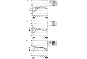
図7は、比較例及び実施例について、加工領域及び耐熱層の耳高部分を説明するための図である。実施例の加工領域は、第1加工領域SA1及び第4加工領域SA4の2つの加工領域を有している。尚、図7においては、複数の加工領域のうちの1つの加工領域を示している。 FIG. 7 is a diagram for explaining the processing region and the ear height portion of the heat-resistant layer in the comparative example and the example. The machining area of the embodiment has two machining areas, a first machining area SA1 and a fourth machining area SA4. In FIG. 7, one of the plurality of processing regions is shown.
図7(a)は、比較例を示す図である。図7(b)は、実施例1を示す図である。図7(c)は、実施例2を示す図である。図7(d)は、実施例3を示す図である。 FIG. 7A illustrates a comparative example. FIG. 7B is a diagram illustrating the first embodiment. FIG. 7C shows the second embodiment. FIG. 7D shows the third embodiment.
尚、図7(a)〜図7(d)において、上段の図は加工領域を示す図である。中段の図は、加工領域の溝の深さの勾配を示す図である。下段の図は、耐熱層における耳高部分の度合いを示す図である。下段の図において、横軸は加工領域の幅方向の位置である。縦軸はフィルム材に形成された耐熱層の厚みである。尚、横軸の左側は加工領域の幅方向の他端E2側に対応する。右側は加工領域の幅方向の一端E1側に対応する。 In FIGS. 7A to 7D, the upper diagram is a diagram showing a processing region. The middle diagram is a diagram showing the gradient of the depth of the groove in the processing region. The lower diagram is a diagram showing the degree of the ear height portion in the heat-resistant layer. In the lower diagram, the horizontal axis represents the position in the width direction of the machining region. The vertical axis represents the thickness of the heat-resistant layer formed on the film material. The left side of the horizontal axis corresponds to the other end E2 side in the width direction of the machining area. The right side corresponds to one end E1 side in the width direction of the processing region.
使用したサンプルは、図7(a)〜(d)の上段に示すように、加工領域の溝の傾斜角度θが45°程度のものを用いた。 As the used sample, as shown in the upper part of FIGS. 7A to 7D, a sample having a groove inclination angle θ of about 45 ° in the processing region was used.
比較例としては、図7(a)の中段に示すように、加工領域全体の溝の深さdが均一になっているものを用いた。溝の深さdは、150μm程度である。 As a comparative example, as shown in the middle part of FIG. 7A, a groove having a uniform groove depth d in the entire processing region was used. The depth d of the groove is about 150 μm.
実施例としては、図7(b)〜(d)の中段に示すように、加工領域が、第1加工領域SA1と、第4加工領域SA4と、を有するものを用いた。第4加工領域SA4の溝の深さdは、比較例と同様、150μm程度である。尚、実施例1〜3においては、第1の長さLが異なるのみである。 As an example, as shown in the middle part of FIGS. 7B to 7D, a processing region having a first processing region SA1 and a fourth processing region SA4 was used. The depth d of the groove in the fourth processing region SA4 is about 150 μm, as in the comparative example. In Examples 1 to 3, only the first length L is different.
実施例1において、第1の長さLは10mm程度である。実施例2において、第1の長さLは30mm程度である。実施例3において、第1の長さLは50mm程度である。 In the first embodiment, the first length L is about 10 mm. In Example 2, the first length L is about 30 mm. In Example 3, the first length L is about 50 mm.
比較例では、図7(a)の下段に示すように、耐熱層の耳高部分が顕著に目立っている(図中丸囲み部)。これは、塗布液が加工領域の流れ方向下流側の領域に偏ったことに起因すると考えられる。 In the comparative example, as shown in the lower part of FIG. 7A, the ear-high portion of the heat-resistant layer is conspicuous (circled portion in the figure). This is considered to be due to the fact that the coating liquid is biased toward the downstream region in the flow direction of the processing region.
耐熱層の耳高部分のうち最も厚い部分の厚みは27μm程度である。耐熱層の中央部の厚みは25μm程度である。耳高部分の最大厚みと中央部の厚みとの差は2μm程度である。この厚みの差は、表面に耐熱層が形成され、巻き取りロール6によって巻き取られる前のフィルム材であれば製造誤差として許容できる厚みの範囲内であると考えられる。しかしながら、巻き取られた後のフィルム材においては皺などが生じ、製品ないしは次工程に適用できなくなることがある。
The thickness of the thickest portion of the heat resistant layer at the ear height is about 27 μm. The thickness of the central part of the heat-resistant layer is about 25 μm. The difference between the maximum thickness of the ear height portion and the thickness of the central portion is about 2 μm. This difference in thickness is considered to be within the range of acceptable thickness as a manufacturing error if the heat resistant layer is formed on the surface and the film material is taken up by the take-
実施例1では、図7(b)の下段に示すように、比較例よりも耐熱層の耳高部分が目立ちにくくなっている(図中丸囲み部)。耐熱層の耳高部分のうち最も厚い部分の厚みは26μm程度である。耐熱層の中央部の厚みは25μm程度である。耳高部分の最大厚みと中央部の厚みとの差は1μm程度である。厚みの差は、比較例よりも小さい結果となった。 In Example 1, as shown in the lower part of FIG. 7B, the ear height portion of the heat-resistant layer is less noticeable than the comparative example (circled portion in the figure). The thickness of the thickest portion of the heat resistant layer is about 26 μm. The thickness of the central part of the heat-resistant layer is about 25 μm. The difference between the maximum thickness of the ear height portion and the thickness of the central portion is about 1 μm. The difference in thickness was smaller than that of the comparative example.
実施例2では、図7(c)の下段に示すように、耐熱層の耳高部分がほとんど目立たなくなっている(図中丸囲み部)。耐熱層の耳高部分のうち最も厚い部分の厚みは25.3μm程度である。耐熱層の中央部の厚みは25μm程度である。耳高部分の最大厚みと中央部の厚みとの差は0.3μm程度である。厚みの差は、実施例1よりも小さい結果となった。 In Example 2, as shown in the lower part of FIG. 7C, the ear height portion of the heat-resistant layer is hardly noticeable (circled portion in the figure). The thickness of the thickest portion of the heat resistant layer at the ear height is about 25.3 μm. The thickness of the central part of the heat-resistant layer is about 25 μm. The difference between the maximum thickness of the ear height portion and the thickness of the central portion is about 0.3 μm. The difference in thickness was smaller than that in Example 1.
実施例3では、図7(d)の下段に示すように、耐熱層の耳高部分がほとんど目立たなくなっている(図中丸囲み部)。しかしながら、耐熱層の幅方向の耐熱層の厚みが両端側で局所的に薄くなっている。これにより、第1の長さLを長くしすぎると、塗布液が加工領域の流れ方向下流側の領域にほとんど保持されなくなることが分かる。 In Example 3, as shown in the lower part of FIG. 7D, the ear height portion of the heat-resistant layer is hardly noticeable (circled portion in the figure). However, the thickness of the heat-resistant layer in the width direction of the heat-resistant layer is locally thin on both ends. Thus, it can be seen that if the first length L is too long, the coating liquid is hardly held in the region downstream in the flow direction of the processing region.
耳高現象を抑制するためには、下記の(1a)式に示す関係を満たすことが好ましい。 In order to suppress the ear height phenomenon, it is preferable to satisfy the relationship represented by the following formula (1a).
5≦L≦50 ・・・(1a)
したがって、上記(1a)式と深さd(d=150μm)から、下記の(1)式に示す関係が成り立つ。
5 ≦ L ≦ 50 (1a)
Therefore, the relationship shown in the following equation (1) is established from the above equation (1a) and the depth d (d = 150 μm).
50/3≦(L/d)≦1000/3 ・・・(1)
このように、フィルム材21に塗布液12aを塗布する場合、耐熱層における耳高部分の度合いと、第1の長さLの深さdに対する比の値(L/d)との間には、一定の関係があることが分かった。
50/3 ≦ (L / d) ≦ 1000/3 (1)
As described above, when the
図8は、比較例及び実施例について、フィルム材の長手方向のある位置を測定したときの、フィルム材に形成された耐熱層の厚みを示す図である。図8において、横軸は加工領域の幅方向の位置である。縦軸はフィルム材に形成された耐熱層の厚みである。尚、図8の横軸は図7の下段の図の横軸と加工領域の幅方向の向きが逆である。図8において、左側は加工領域の幅方向の一端E1側に対応する。右側は加工領域の幅方向の他端E2側に対応する。横軸のピッチ(一目盛)は10mmである。尚、フィルム材の長手方向の長さ1000m程度とする。 FIG. 8: is a figure which shows the thickness of the heat-resistant layer formed in the film material when a certain position of the longitudinal direction of a film material is measured about a comparative example and an Example. In FIG. 8, the horizontal axis represents the position in the width direction of the machining area. The vertical axis represents the thickness of the heat-resistant layer formed on the film material. The horizontal axis in FIG. 8 is opposite to the horizontal axis in the lower diagram of FIG. In FIG. 8, the left side corresponds to one end E1 side in the width direction of the processing region. The right side corresponds to the other end E2 side in the width direction of the processing region. The pitch (scale) on the horizontal axis is 10 mm. The length of the film material in the longitudinal direction is about 1000 m.
図8(a)は、フィルム材の基端から300m程度の位置を測定したときの図である。図8(b)は、フィルム材の基端から500m程度の位置を測定したときの図である。図8(c)は、フィルム材の基端から1000m程度の位置(末端)を測定したときの図である。 Fig.8 (a) is a figure when the position of about 300 m is measured from the base end of a film material. FIG.8 (b) is a figure when the position of about 500m is measured from the base end of a film material. FIG.8 (c) is a figure when the position (terminal) of about 1000 m from the base end of a film material is measured.
図8(a)〜図8(c)に示すように、比較例においては、耐熱層の耳高部分が一端E1側において局所的に厚くなっている。 As shown in FIG. 8A to FIG. 8C, in the comparative example, the ear height portion of the heat-resistant layer is locally thick on the one end E1 side.
これに対し、実施例1〜3においては、耐熱層の厚みが一端E1に近づくに従って徐々に薄くなっている。 On the other hand, in Examples 1-3, the thickness of the heat-resistant layer is gradually reduced as it approaches one end E1.
このように、フィルム材の長手方向の測定位置が異なっていても、フィルム材に形成された耐熱層の厚みについては同様の傾向が認められた。 Thus, even if the measurement position in the longitudinal direction of the film material was different, the same tendency was recognized for the thickness of the heat-resistant layer formed on the film material.
尚、本実施形態においては、一例として、加工領域の溝の傾斜角度θが45°程度のものを挙げて説明したが、これに限らない。例えば、図9(a)に示すように、加工領域の溝の傾斜角度θが30°程度のものも本発明の一実施形態である。また、図9(b)に示すように、加工領域の溝の傾斜角度θが60°程度のものも本発明の一実施形態である。 In the present embodiment, an example in which the groove inclination angle θ of the processing region is about 45 ° has been described as an example, but the present invention is not limited thereto. For example, as shown in FIG. 9 (a), one having an inclination angle θ of the groove in the processing region of about 30 ° is also an embodiment of the present invention. Further, as shown in FIG. 9 (b), one having an inclination angle θ of the groove in the processing region of about 60 ° is also an embodiment of the present invention.
図10は、本実施形態のロール部材30とブレード部材32の位置関係を示す図である。
FIG. 10 is a diagram illustrating a positional relationship between the
図10に示すように、ブレード部材32は、ロール部材30の外周面(加工領域30SAおよび非加工領域30SB)に接触し、加工領域30SAに付着した余分な塗布液12aを掻き取るとともに、非加工領域30SBに付着した塗布液12aを掻き取って非加工領域30SBの塗布液12aを全て除去するものである。ブレード部材32は、本体部321と、ロール部材30の表面と接触する側の部分(ロール部材30と対向する部分)であるエッジ部322と、を有している。ブレード部材32のエッジ部322がロール部材30の非加工領域30SBに接触するようになっている。ブレード部材32のエッジ部322は、中心軸30aに平行な直線形状となっている。
As shown in FIG. 10, the
尚、ブレード部材32は、少なくともエッジ部322がロール部材30よりも弾性率が小さい材料で形成されていることが好ましい。例えば、ロール部材30が鉄やステンレス鋼等の金属材料で形成される場合、ブレード部材32は少なくともエッジ部322がプラスチックやゴム等の樹脂材料で形成される。
The
また、塗布液12aの粘度は0.1Ps以下の粘度に設定することが好ましい。塗布液12aの粘度が0.1Psを超えると、ブレード部材32による非加工領域30SBに付着した塗布液12aの掻き取り効果が低減してしまうからである。
Moreover, it is preferable to set the viscosity of the
図11は、本実施形態のセパレータ製造装置1の作用を説明するための図である。
FIG. 11 is a diagram for explaining the operation of the
図11(a)に示すように、塗布液12aをロール部材30に供給すると、ロール部材30の加工領域30SAだけでなく、非加工領域30SBにも塗布液12aが付着してしまうことがある。
As shown in FIG. 11A, when the
この状態で、ロール部材30をフィルム材21に押し当てながら回転させると、フィルム材21全体に亘って塗布液12aが転写されてしまう。すなわち、耐熱層が、フィルム材において電極板が配置される領域となる形成領域だけでなく、セパレータが熱融着される領域となる非形成領域にも形成されてしまう。そのため、当該フィルム材を基にセパレータが製造されても、当該セパレータを熱融着する際に融着部分の耐熱層によって熱伝導が阻害され、十分な熱融着が行えなくなるという問題が生ずる。
If the
図11(b)に示すように、本実施形態においては、ブレード部材32のエッジ部322によって非加工領域30SBに付着した塗布液12aを掻き取ることができる。
As shown in FIG. 11B, in the present embodiment, the
そのため、図11(c)に示すように、ロール部材30の加工領域30SAにのみ塗布液12aが保持される。これにより、フィルム材21の所望の領域(フィルム材21において電極板が配置される領域となる形成領域10SA)にのみ塗布液12aを転写させることができる。
Therefore, as shown in FIG. 11C, the
図1に戻り、塗布装置3により表面に塗布液12aが転写されたフィルム材21は、搬送下流側の展張ロール8により送り出され、複数の搬送ロール7を経由して乾燥・硬化装置4に導入される。
Returning to FIG. 1, the
乾燥・硬化装置4は、フィルム材21に転写された塗布液12aに含まれる溶媒を乾燥し、固形分であるバインダー樹脂を硬化させるものである。表面に塗布液12aが転写されたフィルム材21を乾燥・硬化装置4に導入することにより、フィルム材21上に耐熱層12が固着する。
The drying /
乾燥・硬化装置4により表面に耐熱層12が固着されたフィルム材21は、複数の搬送ロール7により搬送され、検査装置5の検査領域に導かれる。
The
検査装置5は、表面に耐熱層12が固着したフィルム材21の表面状態を検査するものである。検査装置5は、例えば、カメラ、記憶部、及び判定部を有している。カメラは、フィルム材21の表面を撮像する。記憶部は、カメラが撮像したフィルム材21の表面の画像データを記憶する。判定部は、前記画像データに基づいてフィルム材21の所望の領域に耐熱層12が形成されているか否かを判定する。
The
検査装置5により表面状態が検査されたフィルム材21は、複数の搬送ロール7により搬送され、巻取りロール6によって巻き取られる。
The
図12は、本実施形態のセパレータ10の製造工程を示す図である。図12(a)は、フィルム材21を示す。
FIG. 12 is a diagram illustrating a manufacturing process of the
図12(b)は、フィルム材21上に耐熱層12が形成された状態を示す。保持ロール2に保持されたフィルム材21を繰り出し、上述したように塗布装置3、乾燥・硬化装置4を通過させることによって、その表面に耐熱層12が固着される。フィルム材21は、表面に耐熱層12が形成された形成領域20SAと、表面に耐熱層12が形成されていない非形成領域20SBとを有する。フィルム材21は、5つの形成領域20SAと、4つの非形成領域20SBとを有する。巻取りロール6で、表面に耐熱層12が固着したフィルム材21を巻き取る。
FIG. 12B shows a state in which the heat-
図12(c)に示すように、フィルム材21は、例えばカッター等の切断装置23により、長手方向に沿って、非形成領域20SBの部分で切断される。
As shown in FIG. 12C, the
これにより、図12(d)に示すように、帯状のセパレータ10が製造される。本実施形態では、1つのフィルム材21から3つのセパレータ10が得られる。本実施形態においては、フィルム材21に設けられた5つの形成領域20SAのうち両端部の2つの形成領域20SAはセパレータ10として使用されない。すなわち、中央部の3つの形成領域20SAがセパレータ10として使用される。
Thereby, as shown in FIG.12 (d), the strip | belt-shaped
尚、二次電池に封入される電極捲回体を製造する際には、所定の幅の帯状に製造したセパレータ10を、それぞれ帯状に製造された正電極や負電極とともに捲回する。そして、必要な長さまで捲回したら、これらを切断し、巻き終わりを固定して捲回体とする。また、捲回体ではない積層型の電極を作成する場合にはセパレータ10の長手方向に直交する方向にも切断して当該切断領域で熱融着することになる。この場合においても、切断領域に耐熱層12が塗布されていると、通常の温度で熱融着することが困難となるため好ましくない。そのため、塗布処理の際に、長手方向と直交する方向においても、耐熱層12が塗布されていない非形成領域を間欠的に形成することが好ましい。
In addition, when manufacturing the electrode winding body enclosed with a secondary battery, the
例えば、耐熱層12を形成するための塗布処理を間欠的に行う。具体的には、フィルム材21を一定の速度で送りつつ、耐熱層12を形成するための塗布処理を行わないタイミングを設定する。塗布装置3が、フィルム材21のうち耐熱層12を形成しない領域に対向している間は、塗布装置3とフィルム材21を挟んで対向して配置された2つの展張ロール8のうち一方を塗布装置3とは反対側へ移動させる。これにより、この箇所とロール部材30とが接触しないので、フィルム材21に塗布液12aが塗布されない。フィルム材21のうち耐熱層12を形成しない領域が通り過ぎたら、展張ロール8の配置を元に戻し、再び塗布処理を行う。
For example, the coating process for forming the heat-
このようにすれば、帯状のフィルム材21には、長手方向の両端部及び中間部に加えて、幅方向に間欠的な非形成領域が形成される。そのため、矩形形状の形成領域が縦横に並んだものとなる。その後、切断装置によって長手方向に沿って中間部を切断する。これにより、間欠的に耐熱層12が形成されたセパレータとすることができる。
If it does in this way, in addition to the both ends and intermediate part of a longitudinal direction, the intermittent non-form area | region is formed in the width direction in the strip | belt-shaped
セパレータ10を用いて電極捲回体を形成する際には、セパレータ10や正負の電極板を重ねて必要な長さだけ捲回しつつ巻き出し、最後にそれぞれ切断する。
When the electrode winding body is formed using the
以上、説明したように、本実施形態のロール部材30、セパレータ製造装置1によれば、第1加工領域SA1で保持される塗布液12aの量が第3加工領域SA3で保持される塗布液12aの量よりも少ない。これにより、塗布液12aが加工領域30SAの幅方向の一端E1側に偏って流れても、第1加工領域SA1に塗布液12aが過剰に保持されることを抑制することができる。そのため、フィルム材21の第1加工領域SA1に対応する領域に過剰の塗布液12aが塗布されることを抑制することができる。すなわち、フィルム材21の幅方向において耐熱層12の端部の厚みが過剰に厚くなることを抑制することができる。また、第1加工領域SA1に保持される塗布液12aの厚みが加工領域30SAの幅方向の一端E1に近づくに従って漸次薄くなる。これにより、第1加工領域SA1に保持される塗布液12aの厚みをなだらかにすることができる。そのため、フィルム材21の第1加工領域SA1に対応する領域に形成される耐熱層12の厚みをなだらかにすることができる。よって、耳高現象の発生を抑制するとともに、基材11の表面に耐熱層12を均一に形成可能なロール部材30、セパレータ製造装置1を提供することができる。
As described above, according to the
また、ブレード部材32のエッジ部322によって非加工領域30SBに付着した塗布液12aを掻き取り非加工領域30SBの塗布液12aを全て除去することができる。そのため、セパレータ10が熱融着される領域である非形成領域10SBに耐熱層12が形成されていないセパレータ10を製造することができる。すなわち、セパレータ10が熱融着される領域である非形成領域10SBにおいて基材11を露出させることができる。よって、所望の領域に選択的に耐熱層12が形成されたセパレータ10を製造することができる。
Further, the
また、ロール部材30は中心軸30aに複数の加工領域30SAを有するため、フィルム材21の複数の形成領域20SAに一括して塗布液12aを転写することができる。
Further, since the
また、ブレード部材32のエッジ部322が中心軸30aに平行な直線形状であるため、ロール部材30の加工領域30SAに保持された塗布液12aの量を所定の量に調整しつつ非加工領域30SBに付着した塗布液12aを掻き取ることができる。
Further, since the
また、ブレード部材32のエッジ部322はロール部材30よりも弾性率が小さいため、エッジ部322を撓ませた状態でロール部材30の非加工領域30SBに圧接させることができる。よって、非加工領域30SBに付着した塗布液12aを十分に掻き取ることができる。
Further, since the
尚、本実施形態において、セパレータ10としては帯状のものを挙げて説明したが、これに限らない。例えば、図13に示すように、シート状のセパレータ110を用いることもできる。このシート状のセパレータ110は、積層型の二次電池に適用される。尚、図13においてはセパレータ110の厚み方向(図13中の上下方向)を拡大して示しているが、実際の厚みは幅方向の大きさに対してごく薄いものである。図13に示すように、セパレータ110は矩形形状である。セパレータ110は、表面において中央部に耐熱層112が形成された形成領域110SAと、周縁部に耐熱層112が形成されていない非形成領域110SBと、を有している。
In the present embodiment, the
〔第2実施形態〕
図14は、図3(a)に対応した、本発明の第2実施形態のロール部材130を示す斜視図である。図14に示すように、本実施形態のロール部材130は、中心軸130aに平行な方向において第2の非加工領域130SCを有している点、で上述の第1実施形態のロール部材30と異なっている。その他の点は上述の構成と同様であるので、図3(a)と同様の要素には同一の符号を付し、詳細な説明は省略する。
[Second Embodiment]
FIG. 14 is a perspective view showing a
図14に示すように、ロール部材130は、中心軸130aに平行な方向において、塗布液12aを保持するための加工が周方向に施された加工領域130SAと、塗布液12aを保持するための加工が施されていない第1の非加工領域130SBと、を有している。さらに、ロール部材130は、中心軸130aに平行な方向であって加工領域130SAと直交する方向においても、塗布液12aを保持するための加工が施されていない第2の非加工領域130SCを有している。すなわち、本実施形態の加工領域130SAは、加工領域130SAがロール部材130の周方向において第2の非加工領域130SCにより複数(3つ)に分割されている。
As shown in FIG. 14, the
このような構成によれば、塗布処理の際に、長手方向と直交する方向においても、塗布液12aが塗布されていない非形成領域を間欠的に形成することができる。
According to such a configuration, it is possible to intermittently form a non-formation region where the
尚、本実施形態においては、ロール部材130において加工領域130SAがロール部材130の周方向において第2の非加工領域130SCにより3つに分割されている例を挙げて説明したが、これに限らない。例えば、ロール部材130の周方向における加工領域130SAの分割数は2つでもよいし4つ以上であってもよい。
In the present embodiment, the processing region 130SA of the
また、ロール部材130の直径や長さを適宜変更することにより、所望のパターンの形成領域を得ることができる。
In addition, by appropriately changing the diameter and length of the
図15は、本実施形態のロール部材130を用いた場合におけるセパレータ110の製造工程を示す図である。
FIG. 15 is a diagram illustrating a manufacturing process of the
図15(a)は、フィルム材21を示す。
FIG. 15A shows the
図15(b)は、フィルム材21上に耐熱層112が形成された状態を示す。保持ロール2に保持されたフィルム材21を繰り出し、上述したように本実施形態のロール部材130を備えた塗布装置、乾燥・硬化装置4を通過させることによって、その表面に耐熱層112が固着される。フィルム材21は、表面に耐熱層112が形成された形成領域120SAと、表面に耐熱層112が形成されていない第1の非形成領域120SBと、第2の非形成領域120SCと、を有する。フィルム材21は、25つの形成領域120SAと、フィルム材21の長手方向に平行な4列の第2の非形成領域120SBと、フィルム材21の幅方向に平行な4行の第2の非形成領域120SCと、を有する。巻取りロール6で、表面に耐熱層112が固着したフィルム材21を巻き取る。
FIG. 15B shows a state in which the heat-
図15(c)に示すように、フィルム材21は、例えばカッター等の切断装置23により、長手方向と幅方向のそれぞれに沿って切断される。
As shown in FIG. 15C, the
これにより、図15(d)に示すように、フィルム状のセパレータ110が製造される。本実施形態では、1つのフィルム材21から9つのセパレータ110が得られる。本実施形態においては、フィルム材21に設けられた25の形成領域120SAのうちが外周部の16の形成領域120SAはセパレータ110として使用されない。すなわち、中央部の9つの形成領域120SAがセパレータ110として使用される。
Thereby, as shown in FIG.15 (d), the film-
以下、本実施形態のフィルム状のセパレータ110を用いて二次電池を製造するための二次電池製造装置100について一例を挙げて説明する。
Hereinafter, an example of the secondary
(二次電池製造装置)
図16は、本発明の二次電池製造装置100を示す模式図である。
(Secondary battery manufacturing equipment)
FIG. 16 is a schematic diagram showing a secondary
本発明の二次電池製造装置100は、正極板、負極板、一対のセパレータを含む二次電池を製造するためのものである。二次電池において一対のセパレータは、正極板、負極板をそれぞれ挟み込むものである。
The secondary
図16に示すように、本発明の二次電池製造装置100は、セパレータ製造装置101と、重ね合わせ装置102と、加熱装置103と、を備えている。
As shown in FIG. 16, the secondary
セパレータ製造装置101は、セパレータを製造するものである。尚、セパレータ製造装置1は前記第1実施形態で説明したセパレータ製造装置1について第2実施形態のロール部材130を適用したものを用いる。
The
セパレータ製造装置101は、ロール部材130の加工領域130SAに保持された塗布液12aをセパレータ110の基材111の中央部に転写することにより、中央部に耐熱層12が形成された形成領域110SAを有し且つ周縁部に耐熱層12が形成されていない非形成領域110SBを有するセパレータ110を製造する。
The
重ね合わせ装置102は、一対のセパレータ110の間に正極板又は負極板を挟み込むものである。重ね合わせ装置102は、一対のセパレータ110の形成領域110SAが正極板又は負極板と重なるように配置する。
The stacking
加熱装置103は、一対のセパレータ110を熱融着させるものである。加熱装置103は、正極板又は負極板と重ならないセパレータ110の非形成領域110SBを加熱して一対のセパレータ110を熱融着させる。
The
図17は、二次電池50の要部を示す模式図である。
FIG. 17 is a schematic diagram showing a main part of the
図17に示すように、セパレータ110の形成領域110SAに正極板13が配置されている。正極板13にはタブ14が設けられている。タブ14はセパレータ110の外部に一部露出している。尚、セパレータ110の非形成領域110SBは熱融着される領域である。
As shown in FIG. 17, the
図18は、二次電池50の一部破断斜視図である。
FIG. 18 is a partially broken perspective view of the
図18に示すように、二次電池50は、内部に電解液を貯留する容器51を備える。二次電池50は、例えばリチウムイオン二次電池である。例えば、容器51は、アルミニウム製の中空容器であり、外形が略角柱状(略直方体状)である。容器51は、開口を有する容器本体511と、この開口を塞いで容器本体511に接合された蓋512と、を有している。
As shown in FIG. 18, the
蓋512には、電極端子53、54が設けられている。例えば、電極端子53が正極端子であり、電極端子54が負極端子である。容器51の内部には、複数の電極板13、15および複数のセパレータ10が収容されている。例えば、電極板13が正極板であり、電極板15が負極板である。複数の電極板13、15は、正極板と負極板とが交互に並ぶように繰り返し配置されている。
The
一対のセパレータ10は、電極板13、15をそれぞれ挟み込んでいる。これにより、電極板13、15が互いに直接接触しないようになっている。セパレータ10は、多孔質の絶縁材料等からなり、リチウムイオン等の電解成分を通すようになっている。実際には、正極板13が一対のセパレータ10で挟まれた構造体、負極板15が一対のセパレータ10で挟まれた構造体が交互に積層されて積層体が構成されている。二次電池50は、容器51に前記積層体が収容された構造になっている。電解液は、容器51の内部で電極板13、15と接触するように貯留される。
The pair of
このような二次電池50は、例えば次の方法で得られる。先ず正極板13と負極板15とを用意する。次いで、正極板13と負極板15とをそれぞれ一対のセパレータ10で挟んで積層することにより、積層体を形成する。次いで、容器51の内部に積層体を収容して封止する。例えば、容器本体511に積層体を挿入する。そして、正極板13を正極端子53と電気的に接続し、また負極板15を負極端子54と接続する。そして、容器本体511に蓋512を溶接等により接合する。そして、容器51の内部に電解液を注入して封止すること等により、二次電池50が得られる。
Such a
以上、添付図面を参照しながら本実施形態に係る好適な実施の形態例について説明したが、本発明は係る例に限定されないことは言うまでもない。上述した例において示した各構成部材の諸形状や組み合わせ等は一例であって、本発明の主旨から逸脱しない範囲において設計要求等に基づき種々変更可能である。 As mentioned above, although the suitable embodiment example which concerns on this embodiment was demonstrated referring an accompanying drawing, it cannot be overemphasized that this invention is not limited to the example which concerns. Various shapes, combinations, and the like of the constituent members shown in the above-described examples are examples, and various modifications can be made based on design requirements and the like without departing from the gist of the present invention.
1,101…セパレータ製造装置、10,110…セパレータ、11,111…基材、12,112…耐熱層、3…塗布装置、4…乾燥・硬化装置(乾燥装置)、12a…塗布液、13…正極板、15…負極板、30,130…ロール部材、30a,130a…中心軸、30SA,130SA…加工領域、30SB…非加工領域、130SB…第1の非加工領域、130SC…第2の非加工領域、31…供給部、32…ブレード部材、50…二次電池、100…二次電池製造装置、102…重ね合わせ装置、103…加熱装置、SA1…第1加工領域、SA2…第2加工領域、SA3…第3加工領域、SA4…第4加工領域、d…溝の深さ、E1…加工領域の幅方向の一端、E2…加工領域の幅方向の他端、L…第1の長さ、L2…第2の長さ
DESCRIPTION OF SYMBOLS 1,101 ...
本発明によれば、耳高現象の発生を抑制するとともに、基材の表面に塗膜を均一に形成可能なロール部材、塗布装置、セパレータ製造装置並びに二次電池製造装置を提供することができる。 According to the present invention, it is possible to provide a roll member, a coating apparatus, a separator manufacturing apparatus, and a secondary battery manufacturing apparatus that can suppress the occurrence of an ear height phenomenon and can uniformly form a coating film on the surface of a substrate. .
Claims (10)
前記複数の溝は、前記ロール部材の中心軸に平行な方向に対して斜めに配置され、
前記ロール部材の外周面には、前記複数の溝が形成された加工領域と、前記複数の溝が形成されていない非加工領域と、が設けられ、
前記加工領域は、前記中心軸に平行な前記加工領域の幅方向の一端側に設けられた第1加工領域と、前記加工領域の幅方向の他端側に設けられた第2加工領域と、前記第1加工領域及び前記第2加工領域以外の加工領域である第3加工領域と、を有し、
前記第3加工領域の溝の深さは均一になっており、
前記第1加工領域の溝の深さは前記第3加工領域の溝の深さよりも浅くなっており、
前記第1加工領域の溝の深さは前記加工領域の幅方向の一端に近づくに従って漸次浅くなっており、
前記第2加工領域の溝の深さは前記第3加工領域の溝の深さよりも浅くなっており、
前記第2加工領域の溝の深さは前記加工領域の幅方向の他端に近づくに従って漸次浅くなっており、
前記第1加工領域の前記中心軸に平行な方向の第1の長さと前記第2加工領域の前記中心軸に平行な方向の第2の長さとが互いに異なるロール部材。 A roll member having a plurality of grooves formed on the outer peripheral surface,
The plurality of grooves are arranged obliquely with respect to a direction parallel to the central axis of the roll member,
The outer peripheral surface of the roll member is provided with a processing region in which the plurality of grooves are formed, and a non-processing region in which the plurality of grooves are not formed,
The processing region includes a first processing region provided on one end side in the width direction of the processing region parallel to the central axis, a second processing region provided on the other end side in the width direction of the processing region, A third processing region that is a processing region other than the first processing region and the second processing region;
The depth of the groove in the third processing region is uniform,
The depth of the groove in the first processing region is shallower than the depth of the groove in the third processing region,
The groove depth of the first processing region is gradually shallower as it approaches one end in the width direction of the processing region,
The depth of the groove in the second processing region is shallower than the depth of the groove in the third processing region,
The depth of the groove in the second processing region is gradually shallower as it approaches the other end in the width direction of the processing region,
A roll member in which a first length in a direction parallel to the central axis of the first processing region and a second length in a direction parallel to the central axis of the second processing region are different from each other.
前記複数の溝は、前記ロール部材の中心軸に平行な方向に対して斜めに配置され、
前記ロール部材の外周面には、前記複数の溝が形成された加工領域と、前記複数の溝が形成されていない非加工領域と、が設けられ、
前記加工領域は、前記中心軸に平行な前記加工領域の幅方向の一端側に設けられた第1加工領域と、前記加工領域の前記第1加工領域以外の加工領域である第4加工領域と、を有し、
前記第4加工領域の溝の深さは均一になっており、
前記第1加工領域の溝の深さは前記第4加工領域の溝の深さよりも浅くなっており、
前記第1加工領域の溝の深さは前記加工領域の幅方向の一端に近づくに従って漸次浅くなっているロール部材。 A roll member having a plurality of grooves formed on the outer peripheral surface,
The plurality of grooves are arranged obliquely with respect to a direction parallel to the central axis of the roll member,
The outer peripheral surface of the roll member is provided with a processing region in which the plurality of grooves are formed, and a non-processing region in which the plurality of grooves are not formed,
The machining area includes a first machining area provided on one end side in the width direction of the machining area parallel to the central axis, and a fourth machining area that is a machining area other than the first machining area of the machining area; Have
The depth of the groove in the fourth processing region is uniform,
The depth of the groove in the first processing region is shallower than the depth of the groove in the fourth processing region,
The roll member in which the depth of the groove in the first processing region gradually becomes shallower as it approaches one end in the width direction of the processing region.
50/3≦(L/d)≦1000/3 ・・・(1) When the depth of the groove farthest from the first end of the first processing region is d and the length of the first processing region in the direction parallel to the central axis is L, the following (1) The roll member according to claim 1 or 2 satisfying a formula.
50/3 ≦ (L / d) ≦ 1000/3 (1)
中心軸の周りに回転可能に配置された請求項1または請求項2に記載のロール部材と、
前記ロール部材の外周面に前記塗布液を供給する供給部と、
前記ロール部材の外周面に付着した余分な前記塗布液を掻き取るブレード部材と、を含み、
前記ブレード部材は、前記ロール部材の前記加工領域および前記非加工領域に接触し、前記加工領域に付着した余分な前記塗布液を掻き取るとともに、前記非加工領域に付着した前記塗布液を掻き取り前記非加工領域の前記塗布液を全て除去するように構成されている塗布装置。 A coating apparatus for applying a coating liquid to a film material,
The roll member according to claim 1, wherein the roll member is rotatably arranged around a central axis;
A supply unit for supplying the coating liquid to the outer peripheral surface of the roll member;
A blade member that scrapes off the excess coating liquid adhering to the outer peripheral surface of the roll member, and
The blade member is in contact with the processing region and the non-processing region of the roll member, scrapes off the excess coating liquid adhering to the processing region, and scrapes off the coating liquid adhering to the non-processing region. A coating apparatus configured to remove all of the coating liquid in the non-processed area.
請求項5に記載の塗布装置と、
前記塗布装置により前記基材となるフィルム材に転写された前記耐熱層の形成材料を含む塗布液を乾燥させる乾燥装置と、
を含むセパレータ製造装置。 A separator manufacturing apparatus for manufacturing a separator in which a heat-resistant layer is laminated on a substrate,
A coating apparatus according to claim 5;
A drying device for drying the coating solution containing the material for forming the heat-resistant layer transferred to the film material serving as the substrate by the coating device;
Separator manufacturing apparatus.
請求項9に記載のセパレータ製造装置と、
前記セパレータ製造装置によって製造された一対のセパレータの間に前記正極板又は前記負極板を挟み込む重ね合わせ装置と、前記正極板又は前記負極板を挟み込んでいる前記一対のセパレータの周縁部を加熱して前記一対のセパレータを熱融着させる加熱装置と、
を含み、
前記セパレータ製造装置は、前記ロール部材の前記加工領域に保持された前記塗布液を前記セパレータの基材の中央部に転写することにより、中央部に前記耐熱層が形成された形成領域を有し且つ周縁部に前記耐熱層が形成されていない非形成領域を有するセパレータを製造する装置であり、
前記重ね合わせ装置は、前記一対のセパレータの前記形成領域が前記正極板又は前記負極板と重なるように前記一対のセパレータを配置する装置であり、
前記加熱装置は、前記正極板又は前記負極板と重ならない前記セパレータの前記非形成領域を加熱して前記一対のセパレータを熱融着させる装置である二次電池製造装置。 A secondary battery manufacturing apparatus for manufacturing a secondary battery including a positive electrode plate, a negative electrode plate, and a pair of separators sandwiching the positive electrode plate or the negative electrode plate,
The separator manufacturing apparatus according to claim 9,
A stacking device that sandwiches the positive electrode plate or the negative electrode plate between a pair of separators manufactured by the separator manufacturing device, and a peripheral portion of the pair of separators that sandwich the positive electrode plate or the negative electrode plate. A heating device for heat-sealing the pair of separators;
Including
The separator manufacturing apparatus has a formation region in which the heat-resistant layer is formed in a central portion by transferring the coating liquid held in the processing region of the roll member to the central portion of the base material of the separator. And it is an apparatus for manufacturing a separator having a non-formation region in which the heat-resistant layer is not formed in the peripheral part,
The overlapping device is a device that arranges the pair of separators so that the formation region of the pair of separators overlaps the positive electrode plate or the negative electrode plate,
The said heating apparatus is a secondary battery manufacturing apparatus which is an apparatus which heats the said non-formation area | region of the said separator which does not overlap with the said positive electrode plate or the said negative electrode plate, and heat-fuses a pair of said separator.
Applications Claiming Priority (2)
| Application Number | Priority Date | Filing Date | Title |
|---|---|---|---|
| JP2012174021 | 2012-08-06 | ||
| JP2012174021 | 2012-08-06 |
Related Parent Applications (1)
| Application Number | Title | Priority Date | Filing Date |
|---|---|---|---|
| JP2014529570A Division JP6337773B2 (en) | 2012-08-06 | 2013-08-02 | Roll member, coating device, separator manufacturing device, and secondary battery manufacturing device |
Publications (2)
| Publication Number | Publication Date |
|---|---|
| JP2018155407A true JP2018155407A (en) | 2018-10-04 |
| JP6524307B2 JP6524307B2 (en) | 2019-06-05 |
Family
ID=50068221
Family Applications (2)
| Application Number | Title | Priority Date | Filing Date |
|---|---|---|---|
| JP2014529570A Active JP6337773B2 (en) | 2012-08-06 | 2013-08-02 | Roll member, coating device, separator manufacturing device, and secondary battery manufacturing device |
| JP2018090954A Active JP6524307B2 (en) | 2012-08-06 | 2018-05-09 | Method of manufacturing separator |
Family Applications Before (1)
| Application Number | Title | Priority Date | Filing Date |
|---|---|---|---|
| JP2014529570A Active JP6337773B2 (en) | 2012-08-06 | 2013-08-02 | Roll member, coating device, separator manufacturing device, and secondary battery manufacturing device |
Country Status (5)
| Country | Link |
|---|---|
| US (2) | US9656285B2 (en) |
| JP (2) | JP6337773B2 (en) |
| KR (2) | KR101949479B1 (en) |
| CN (2) | CN104520013B (en) |
| WO (1) | WO2014025004A1 (en) |
Families Citing this family (25)
| Publication number | Priority date | Publication date | Assignee | Title |
|---|---|---|---|---|
| JP6404071B2 (en) * | 2014-10-03 | 2018-10-10 | 旭化成株式会社 | Method for manufacturing separator for power storage device |
| JP5885888B1 (en) * | 2014-12-25 | 2016-03-16 | 住友化学株式会社 | Separator manufacturing method and slitting method |
| CN107627335B (en) * | 2014-12-25 | 2019-08-02 | 住友化学株式会社 | Separator manufacturing method |
| CN107534116B (en) * | 2015-03-02 | 2020-10-09 | 株式会社Lg化学 | Method and apparatus for manufacturing separation membrane for electrochemical device |
| JP6493747B2 (en) * | 2015-04-14 | 2019-04-03 | トヨタ自動車株式会社 | Nonaqueous electrolyte secondary battery separator and method for producing the same |
| JP6023373B1 (en) * | 2015-10-30 | 2016-11-09 | 住友化学株式会社 | Separator manufacturing method and separator manufacturing apparatus |
| US10770707B2 (en) | 2015-12-04 | 2020-09-08 | Toray Industries, Inc. | Battery separator and method of manufacturing same |
| JP6017010B1 (en) | 2015-12-22 | 2016-10-26 | 住友化学株式会社 | Method for producing separator film for lithium ion secondary battery and apparatus for producing separator film for lithium ion secondary battery |
| KR20180096618A (en) * | 2015-12-24 | 2018-08-29 | 도레이 카부시키가이샤 | Polyolefin microporous membrane, battery separator and method of manufacturing them |
| JP2017130269A (en) * | 2016-01-18 | 2017-07-27 | 株式会社Gsユアサ | Power storage element |
| JP6381652B2 (en) | 2016-04-15 | 2018-08-29 | 住友化学株式会社 | Porous separator length, manufacturing method thereof, wound body and lithium ion battery |
| CN105772371A (en) * | 2016-04-29 | 2016-07-20 | 宁德卓高新材料科技有限公司 | Method for improving wavy edge of diaphragm through adopting slightly concave printing roller and slightly concave printing roller |
| KR101888793B1 (en) * | 2016-08-29 | 2018-08-14 | 스미또모 가가꾸 가부시키가이샤 | Winding core, separator roll |
| DE102016218490A1 (en) | 2016-09-27 | 2018-03-29 | Robert Bosch Gmbh | Method for producing a film stack for a battery cell |
| GB2560577B (en) * | 2017-03-17 | 2022-06-22 | Chesterfelt Ltd | Apparatus for the production of a waterproof membrane |
| CN110462879A (en) * | 2017-03-31 | 2019-11-15 | 远景Aesc能源元器件有限公司 | The joint method of separator, the manufacturing method of electrochemical device and electrochemical device |
| CN107309140B (en) * | 2017-08-04 | 2020-03-17 | 北京首钢股份有限公司 | Strip steel production system and method |
| KR102223722B1 (en) | 2017-10-24 | 2021-03-05 | 주식회사 엘지화학 | Lamination apparatus and method for secondary battery |
| WO2019181581A1 (en) * | 2018-03-20 | 2019-09-26 | 積水化学工業株式会社 | Coating device and coating method |
| TWI668460B (en) * | 2018-06-12 | 2019-08-11 | 致茂電子股份有限公司 | Clipped testing device |
| DE102018219000A1 (en) * | 2018-11-07 | 2020-05-07 | Volkswagen Aktiengesellschaft | Process for producing a cathode device, process for producing an electrode assembly and battery |
| KR20210115865A (en) * | 2020-03-16 | 2021-09-27 | 주식회사 엘지에너지솔루션 | Sealing device and method secondary battery |
| WO2022039497A1 (en) * | 2020-08-21 | 2022-02-24 | 주식회사 엘지에너지솔루션 | Adhesive layer coating part, and manufacturing apparatus and method for electrode assembly comprising same |
| US20220219195A1 (en) * | 2021-01-12 | 2022-07-14 | Airbus Operations Gmbh | Device for lacquer transfer |
| CN112934601B (en) * | 2021-01-26 | 2022-12-30 | 安徽钰铭汽车配件有限公司 | Crooked rubber coating formula car filter element processingequipment |
Family Cites Families (16)
| Publication number | Priority date | Publication date | Assignee | Title |
|---|---|---|---|---|
| GB1542131A (en) * | 1975-02-19 | 1979-03-14 | Fuji Photo Film Co Ltd | Light-sensitive printing plate precursors and process for the production thereof |
| US4227452A (en) * | 1977-10-14 | 1980-10-14 | Fuji Xerox Co., Ltd. | Printing machine |
| JPS6175870U (en) * | 1984-10-19 | 1986-05-22 | ||
| JP3783341B2 (en) * | 1997-06-16 | 2006-06-07 | 凸版印刷株式会社 | Gravure coating version |
| JP2004500686A (en) * | 1999-12-09 | 2004-01-08 | 日本特殊陶業株式会社 | Lithium ion battery separator and / or lithium ion polymer battery |
| US6558466B2 (en) * | 1999-12-15 | 2003-05-06 | Eastman Kodak Company | Apparatus for coating a web |
| JP2003236039A (en) | 2002-02-15 | 2003-08-26 | Aruze Corp | Game machine |
| JP3904465B2 (en) * | 2002-03-08 | 2007-04-11 | 富士フイルム株式会社 | Gravure coating method and apparatus |
| JP4403698B2 (en) * | 2002-12-17 | 2010-01-27 | パナソニック株式会社 | Winding battery manufacturing method |
| EP1626109A1 (en) * | 2004-08-11 | 2006-02-15 | "VLAAMSE INSTELLING VOOR TECHNOLOGISCH ONDERZOEK", afgekort "V.I.T.O." | Web-reinforced separator and continuous method for producing same |
| US20060138693A1 (en) * | 2004-12-29 | 2006-06-29 | Tuman Scott J | Method and apparatus for making a cleaning sheet |
| JP4984446B2 (en) * | 2005-07-11 | 2012-07-25 | 大日本印刷株式会社 | Method for forming light emitting layer, hole injection layer, and method for manufacturing organic light emitting device using them |
| JP2007061709A (en) | 2005-08-30 | 2007-03-15 | Fujifilm Corp | Bar coating method and bar coating apparatus |
| JP2011005454A (en) * | 2009-06-29 | 2011-01-13 | Dainippon Printing Co Ltd | Gravure plate and transferring foil using the same |
| JP2011159434A (en) | 2010-01-29 | 2011-08-18 | Toyota Motor Corp | Separator and manufacturing method thereof |
| JP5418391B2 (en) * | 2010-04-27 | 2014-02-19 | 日産自動車株式会社 | Separator |
-
2013
- 2013-08-02 JP JP2014529570A patent/JP6337773B2/en active Active
- 2013-08-02 WO PCT/JP2013/071580 patent/WO2014025004A1/en active Application Filing
- 2013-08-02 CN CN201380041259.4A patent/CN104520013B/en active Active
- 2013-08-02 KR KR1020157005193A patent/KR101949479B1/en active IP Right Grant
- 2013-08-02 KR KR1020197003882A patent/KR102018485B1/en active IP Right Grant
- 2013-08-02 CN CN201810013348.2A patent/CN108054326A/en active Pending
- 2013-08-02 US US14/416,523 patent/US9656285B2/en active Active
-
2017
- 2017-04-19 US US15/491,140 patent/US10179341B2/en active Active
-
2018
- 2018-05-09 JP JP2018090954A patent/JP6524307B2/en active Active
Also Published As
| Publication number | Publication date |
|---|---|
| US20150202647A1 (en) | 2015-07-23 |
| US20170282204A1 (en) | 2017-10-05 |
| JP6337773B2 (en) | 2018-06-06 |
| WO2014025004A1 (en) | 2014-02-13 |
| US9656285B2 (en) | 2017-05-23 |
| KR20150042217A (en) | 2015-04-20 |
| CN108054326A (en) | 2018-05-18 |
| KR20190016617A (en) | 2019-02-18 |
| KR101949479B1 (en) | 2019-02-19 |
| JPWO2014025004A1 (en) | 2016-07-25 |
| KR102018485B1 (en) | 2019-10-21 |
| US10179341B2 (en) | 2019-01-15 |
| JP6524307B2 (en) | 2019-06-05 |
| CN104520013A (en) | 2015-04-15 |
| CN104520013B (en) | 2018-02-06 |
Similar Documents
| Publication | Publication Date | Title |
|---|---|---|
| JP6524307B2 (en) | Method of manufacturing separator | |
| KR102112194B1 (en) | Apparatus of manufacturing a sheet for a secondary battery cell pouch | |
| JP5742784B2 (en) | Coating apparatus, method for producing coated material, method for producing separator heat-resistant film, method for producing separator with heat-resistant film, and method for producing battery | |
| JP2011159434A (en) | Separator and manufacturing method thereof | |
| JP2009262070A (en) | Coating film forming apparatus, coating film forming method, polar plate for cell, and nonaqueous electrolyte secondary cell | |
| JP6705126B2 (en) | Method for manufacturing electrode plate | |
| JP2016181345A (en) | Method for manufacturing secondary battery | |
| JP2021010867A (en) | Coating apparatus and manufacturing method of electrode for battery | |
| JP2007273126A (en) | Forming method of porous heatproof layer and forming device of porous heatproof layer | |
| JP4719903B2 (en) | Coating method and coating apparatus for coating agent | |
| JP4719904B2 (en) | Coating method and coating apparatus for coating agent | |
| JP2015176842A (en) | Production apparatus of sheet for lithium ion secondary battery, production method of sheet for lithium ion secondary battery, and manufacturing method for lithium ion secondary battery | |
| US10518467B2 (en) | Method for producing film | |
| JP6054803B2 (en) | Secondary battery electrode manufacturing apparatus and electrode manufacturing method | |
| JP5644737B2 (en) | Coating apparatus and electrode manufacturing method | |
| JP2019029308A (en) | Manufacturing method of electrode | |
| JP2018181781A (en) | Electrode plate manufacturing device | |
| JP2007273125A (en) | Forming method of porous heatproof layer and forming device of porous heatproof layer | |
| JP6299573B2 (en) | Coating equipment | |
| US20170244084A1 (en) | Expander device, porous film production apparatus, and porous film producing method | |
| KR101717004B1 (en) | Method for producing separator and method for slitting | |
| JP6075184B2 (en) | Electrode transfer sheet for fuel cell, membrane electrode assembly manufacturing apparatus, and method of manufacturing membrane electrode assembly | |
| JP2015112533A (en) | Coating device | |
| JP2018018680A (en) | Method for manufacturing electrode | |
| JPH11317220A (en) | Production of sheet electrode |
Legal Events
| Date | Code | Title | Description |
|---|---|---|---|
| TRDD | Decision of grant or rejection written | ||
| A01 | Written decision to grant a patent or to grant a registration (utility model) |
Free format text: JAPANESE INTERMEDIATE CODE: A01 Effective date: 20190409 |
|
| A61 | First payment of annual fees (during grant procedure) |
Free format text: JAPANESE INTERMEDIATE CODE: A61 Effective date: 20190426 |
|
| R150 | Certificate of patent or registration of utility model |
Ref document number: 6524307 Country of ref document: JP Free format text: JAPANESE INTERMEDIATE CODE: R150 |
|
| S531 | Written request for registration of change of domicile |
Free format text: JAPANESE INTERMEDIATE CODE: R313531 |
|
| R350 | Written notification of registration of transfer |
Free format text: JAPANESE INTERMEDIATE CODE: R350 |