JP2018155251A - Dense phase pump having part replaceable easily - Google Patents
Dense phase pump having part replaceable easily Download PDFInfo
- Publication number
- JP2018155251A JP2018155251A JP2018114121A JP2018114121A JP2018155251A JP 2018155251 A JP2018155251 A JP 2018155251A JP 2018114121 A JP2018114121 A JP 2018114121A JP 2018114121 A JP2018114121 A JP 2018114121A JP 2018155251 A JP2018155251 A JP 2018155251A
- Authority
- JP
- Japan
- Prior art keywords
- pinch valve
- pump
- housing
- powder
- valve housing
- Prior art date
- Legal status (The legal status is an assumption and is not a legal conclusion. Google has not performed a legal analysis and makes no representation as to the accuracy of the status listed.)
- Pending
Links
Images


Classifications
-
- F—MECHANICAL ENGINEERING; LIGHTING; HEATING; WEAPONS; BLASTING
- F16—ENGINEERING ELEMENTS AND UNITS; GENERAL MEASURES FOR PRODUCING AND MAINTAINING EFFECTIVE FUNCTIONING OF MACHINES OR INSTALLATIONS; THERMAL INSULATION IN GENERAL
- F16K—VALVES; TAPS; COCKS; ACTUATING-FLOATS; DEVICES FOR VENTING OR AERATING
- F16K7/00—Diaphragm valves or cut-off apparatus, e.g. with a member deformed, but not moved bodily, to close the passage ; Pinch valves
- F16K7/02—Diaphragm valves or cut-off apparatus, e.g. with a member deformed, but not moved bodily, to close the passage ; Pinch valves with tubular diaphragm
- F16K7/04—Diaphragm valves or cut-off apparatus, e.g. with a member deformed, but not moved bodily, to close the passage ; Pinch valves with tubular diaphragm constrictable by external radial force
- F16K7/07—Diaphragm valves or cut-off apparatus, e.g. with a member deformed, but not moved bodily, to close the passage ; Pinch valves with tubular diaphragm constrictable by external radial force by means of fluid pressure
-
- B—PERFORMING OPERATIONS; TRANSPORTING
- B05—SPRAYING OR ATOMISING IN GENERAL; APPLYING FLUENT MATERIALS TO SURFACES, IN GENERAL
- B05B—SPRAYING APPARATUS; ATOMISING APPARATUS; NOZZLES
- B05B7/00—Spraying apparatus for discharge of liquids or other fluent materials from two or more sources, e.g. of liquid and air, of powder and gas
- B05B7/14—Spraying apparatus for discharge of liquids or other fluent materials from two or more sources, e.g. of liquid and air, of powder and gas designed for spraying particulate materials
- B05B7/1404—Arrangements for supplying particulate material
- B05B7/1459—Arrangements for supplying particulate material comprising a chamber, inlet and outlet valves upstream and downstream the chamber and means for alternately sucking particulate material into and removing particulate material from the chamber through the valves
-
- F—MECHANICAL ENGINEERING; LIGHTING; HEATING; WEAPONS; BLASTING
- F04—POSITIVE - DISPLACEMENT MACHINES FOR LIQUIDS; PUMPS FOR LIQUIDS OR ELASTIC FLUIDS
- F04B—POSITIVE-DISPLACEMENT MACHINES FOR LIQUIDS; PUMPS
- F04B15/00—Pumps adapted to handle specific fluids, e.g. by selection of specific materials for pumps or pump parts
- F04B15/02—Pumps adapted to handle specific fluids, e.g. by selection of specific materials for pumps or pump parts the fluids being viscous or non-homogeneous
-
- F—MECHANICAL ENGINEERING; LIGHTING; HEATING; WEAPONS; BLASTING
- F04—POSITIVE - DISPLACEMENT MACHINES FOR LIQUIDS; PUMPS FOR LIQUIDS OR ELASTIC FLUIDS
- F04B—POSITIVE-DISPLACEMENT MACHINES FOR LIQUIDS; PUMPS
- F04B43/00—Machines, pumps, or pumping installations having flexible working members
- F04B43/0009—Special features
- F04B43/0054—Special features particularities of the flexible members
-
- F—MECHANICAL ENGINEERING; LIGHTING; HEATING; WEAPONS; BLASTING
- F04—POSITIVE - DISPLACEMENT MACHINES FOR LIQUIDS; PUMPS FOR LIQUIDS OR ELASTIC FLUIDS
- F04B—POSITIVE-DISPLACEMENT MACHINES FOR LIQUIDS; PUMPS
- F04B43/00—Machines, pumps, or pumping installations having flexible working members
- F04B43/08—Machines, pumps, or pumping installations having flexible working members having tubular flexible members
-
- F—MECHANICAL ENGINEERING; LIGHTING; HEATING; WEAPONS; BLASTING
- F04—POSITIVE - DISPLACEMENT MACHINES FOR LIQUIDS; PUMPS FOR LIQUIDS OR ELASTIC FLUIDS
- F04B—POSITIVE-DISPLACEMENT MACHINES FOR LIQUIDS; PUMPS
- F04B53/00—Component parts, details or accessories not provided for in, or of interest apart from, groups F04B1/00 - F04B23/00 or F04B39/00 - F04B47/00
- F04B53/10—Valves; Arrangement of valves
-
- F—MECHANICAL ENGINEERING; LIGHTING; HEATING; WEAPONS; BLASTING
- F04—POSITIVE - DISPLACEMENT MACHINES FOR LIQUIDS; PUMPS FOR LIQUIDS OR ELASTIC FLUIDS
- F04B—POSITIVE-DISPLACEMENT MACHINES FOR LIQUIDS; PUMPS
- F04B53/00—Component parts, details or accessories not provided for in, or of interest apart from, groups F04B1/00 - F04B23/00 or F04B39/00 - F04B47/00
- F04B53/20—Filtering
-
- F—MECHANICAL ENGINEERING; LIGHTING; HEATING; WEAPONS; BLASTING
- F16—ENGINEERING ELEMENTS AND UNITS; GENERAL MEASURES FOR PRODUCING AND MAINTAINING EFFECTIVE FUNCTIONING OF MACHINES OR INSTALLATIONS; THERMAL INSULATION IN GENERAL
- F16K—VALVES; TAPS; COCKS; ACTUATING-FLOATS; DEVICES FOR VENTING OR AERATING
- F16K15/00—Check valves
- F16K15/02—Check valves with guided rigid valve members
- F16K15/04—Check valves with guided rigid valve members shaped as balls
- F16K15/044—Check valves with guided rigid valve members shaped as balls spring-loaded
-
- Y—GENERAL TAGGING OF NEW TECHNOLOGICAL DEVELOPMENTS; GENERAL TAGGING OF CROSS-SECTIONAL TECHNOLOGIES SPANNING OVER SEVERAL SECTIONS OF THE IPC; TECHNICAL SUBJECTS COVERED BY FORMER USPC CROSS-REFERENCE ART COLLECTIONS [XRACs] AND DIGESTS
- Y10—TECHNICAL SUBJECTS COVERED BY FORMER USPC
- Y10T—TECHNICAL SUBJECTS COVERED BY FORMER US CLASSIFICATION
- Y10T137/00—Fluid handling
- Y10T137/0318—Processes
- Y10T137/0402—Cleaning, repairing, or assembling
- Y10T137/0441—Repairing, securing, replacing, or servicing pipe joint, valve, or tank
-
- Y—GENERAL TAGGING OF NEW TECHNOLOGICAL DEVELOPMENTS; GENERAL TAGGING OF CROSS-SECTIONAL TECHNOLOGIES SPANNING OVER SEVERAL SECTIONS OF THE IPC; TECHNICAL SUBJECTS COVERED BY FORMER USPC CROSS-REFERENCE ART COLLECTIONS [XRACs] AND DIGESTS
- Y10—TECHNICAL SUBJECTS COVERED BY FORMER USPC
- Y10T—TECHNICAL SUBJECTS COVERED BY FORMER US CLASSIFICATION
- Y10T137/00—Fluid handling
- Y10T137/8593—Systems
- Y10T137/85978—With pump
Landscapes
- Engineering & Computer Science (AREA)
- General Engineering & Computer Science (AREA)
- Mechanical Engineering (AREA)
- Physics & Mathematics (AREA)
- Fluid Mechanics (AREA)
- Nozzles (AREA)
- Details Of Reciprocating Pumps (AREA)
- Jet Pumps And Other Pumps (AREA)
- Coating Apparatus (AREA)
- Check Valves (AREA)
Abstract
Description
本発明は包括的には、粉体コーティング材料をワークピースすなわち対象物上に噴霧するのに使用される材料塗布システムに関する。本発明はより詳細には、材料塗布ポンプ、例えば濃厚相ポンプに関する。 The present invention relates generally to a material application system used to spray powder coating material onto a workpiece or object. The present invention relates more particularly to material application pumps, such as dense phase pumps.
紛体コーティング材料を対象物、部品若しくは他のワークピース又は表面に塗布するのに材料塗布装置が使用される。材料塗布装置は、本明細書においてスプレーガンとも呼ばれる。紛体コーティング材料は、紛体ポンプからスプレーガンに希薄相又は濃厚相で送出することができる。希薄相送出系は、希薄混合気である、すなわち、換言すれば、紛体に対する空気流の比がより高い、紛体流又は紛体ストリームを指す。希薄相紛体ポンプは、ベンチュリ式ポンプの形態で用いられることが最も一般的であり、ベンチュリ式ポンプは供給部から紛体を引き込んでスプレーガンに押し出すのに大量の空気を用いる。濃厚相送出系は、濃厚混合気である、すなわち、換言すれば、紛体に対する空気流の比がより低い、紛体ストリームを指す。濃厚相ポンプは、ポンプチャンバーの形態で用いられることが一般的であり、ポンプチャンバーは、ポンプチャンバーを満たすのに、またポンプチャンバーを空にするのに圧力を用いるが、ただし、以下で空気流と呼ぶ、より少ない空気流量を用いる。濃厚相送出システムは用いる空気流がより少ないため、紛体ホースの直径は、希薄相送出システムとともに用いる紛体ホースと比較してより小さくすることができる。 A material applicator is used to apply the powder coating material to an object, part or other workpiece or surface. The material applicator is also referred to herein as a spray gun. The powder coating material can be delivered from the powder pump to the spray gun in a lean or rich phase. A lean phase delivery system refers to a powder stream or powder stream that is a lean mixture, i.e., a higher ratio of air flow to powder. Lean phase powder pumps are most commonly used in the form of a venturi pump, which uses a large amount of air to draw the powder from the supply and push it into the spray gun. Rich phase delivery system refers to a powder stream that is a rich mixture, i.e., a lower ratio of air flow to powder. Rich phase pumps are typically used in the form of pump chambers, which use pressure to fill the pump chamber and to empty the pump chamber, provided that air flow is Use a lower air flow rate. Because the dense phase delivery system uses less air flow, the diameter of the powder hose can be smaller compared to the powder hose used with the lean phase delivery system.
濃厚相ポンプの一例が、米国特許第7,997,878号(以下、「878号特許」)に記載されており、この米国特許の開示全体は引用することによりその全体が本明細書の一部をなす。 An example of a dense phase pump is described in US Pat. No. 7,997,878 (hereinafter “878 patent”), the entire disclosure of which is hereby incorporated by reference in its entirety. Part.
本開示に提示されている一実施形態では、濃厚相ポンプは、単一の解放可能な締結具によって第1のハウジングに取り付けられている第1のハウジング及び第2のハウジングを有する。より詳細な実施形態では、第2のハウジングは1つ又は複数の交換可能な部品を収納する。別の実施形態では、交換可能な部品は、ピンチ弁、又は、例えば障壁フィルター等の障壁部材、又はそれらの双方を含むことができる。 In one embodiment presented in the present disclosure, a dense phase pump has a first housing and a second housing attached to the first housing by a single releasable fastener. In a more detailed embodiment, the second housing houses one or more replaceable parts. In another embodiment, the replaceable part may include a pinch valve, or a barrier member such as a barrier filter, or both.
濃厚相ポンプ内に配置されている交換可能な部品、例えばピンチ弁又は障壁部材を取り外す又は交換する方法も提供され、例示的な実施形態では、本方法は、交換可能な部品へのアクセスを提供するように単一の解放可能な締結具を解放することを含む。 Also provided is a method of removing or replacing a replaceable part, such as a pinch valve or barrier member, located in the dense phase pump, and in an exemplary embodiment, the method provides access to the replaceable part. Releasing a single releasable fastener.
本明細書に示されている別の実施形態では、ピンチ弁は、第1の端フランジ及び第2の端フランジを有する環状体を有する。端フランジのうちの一方又は双方は、ピンチ弁がピンチ弁ハウジングすなわち弁ボディ内に設置される際にピンチ弁を位置合わせする非円形外形を有する。 In another embodiment shown herein, the pinch valve has an annulus having a first end flange and a second end flange. One or both of the end flanges has a non-circular profile that aligns the pinch valve when the pinch valve is installed in the pinch valve housing or valve body.
本開示に提示されている別の実施形態では、濃厚相ポンプは、少なくとも1つのガス透過性部材を有するポンプハウジングを有し、ガス透過性部材は、ガス透過性部材の一端からガス透過性部材の長手方向軸に沿ってパージすることができ、また、ポンプハウジングは、ガス透過性部材の長手方向軸を横断する軸に沿ってパージ空気がポンプハウジングに入るようにパージ入口を有する。 In another embodiment presented in the present disclosure, the dense phase pump has a pump housing having at least one gas permeable member, the gas permeable member from one end of the gas permeable member. And the pump housing has a purge inlet so that purge air enters the pump housing along an axis transverse to the longitudinal axis of the gas permeable member.
別の実施形態では、ピンチ弁ハウジングは、互いから径方向にずれている2つの端フランジを有する非円形ピンチ弁を有する。 In another embodiment, the pinch valve housing has a non-circular pinch valve having two end flanges that are radially offset from each other.
別の実施形態では、ピンチ弁は、ピンチ弁がピンチ弁ハウジングに組み入れられる際のピンチ弁の正確な向きを示す位置合わせ表示を有する。 In another embodiment, the pinch valve has an alignment indicator that indicates the exact orientation of the pinch valve when the pinch valve is incorporated into the pinch valve housing.
別の実施形態では、ともに組み付けられる2つ以上のハウジングを有する濃厚相ポンプは、ハウジングの外面上に位置合わせ表示を有する。 In another embodiment, a dense phase pump having two or more housings assembled together has an alignment indicator on the outer surface of the housing.
本発明のこれらの態様及び利点並びに他の態様及び利点は、添付の図面に照らして例示的な実施形態の以下の詳細な記載から当業者に認識及び理解されるであろう。 These and other aspects and advantages of the present invention will be appreciated and understood by those skilled in the art from the following detailed description of exemplary embodiments in light of the accompanying drawings.
本発明は、878号特許に記載されている実施形態のような濃厚相ポンプの例示的な実施形態に関して記載されているが、その例示的な実施形態は、本発明のうちの1つ又は複数を用いることができる濃厚相ポンプの1つの例にすぎない。本明細書における本開示及び本発明は、「濃厚相」の厳格な定義に限定されず、そうではなく、ガス透過性フィルターの利用により、紛体コーティング材料が負圧によってポンプチャンバーに引き込まれて正圧によってポンプチャンバーから押し出されるものとしての濃厚相ポンプを指す。また、878号特許に記載されている濃厚相ポンプは、商業的に優れた成果が見出されているが、本発明者らは、摩耗部品の保守整備性を高めるとともにポンプ及びアセンブリの単純化も図る変更及び特徴を編み出している。しかしながら、本明細書における発明的概念及び改善が、本明細書又は878号特許に記載されている以外の付加的又は代替的な濃厚相ポンプ設計とともに用いられることができることに留意することが重要である。 Although the present invention has been described with reference to an exemplary embodiment of a dense phase pump, such as the embodiment described in the '878 patent, the exemplary embodiment can include one or more of the present inventions. Is just one example of a dense phase pump that can be used. The present disclosure and the invention herein are not limited to the strict definition of “rich phase”; rather, the use of a gas permeable filter causes the powder coating material to be drawn into the pump chamber by a negative pressure. Refers to a dense phase pump as it is pushed out of the pump chamber by pressure. Also, the dense phase pump described in the '878 patent has found excellent commercial results, but the inventors have improved the serviceability of wear parts and simplified the pump and assembly. We have also developed changes and features that we plan to pursue. However, it is important to note that the inventive concepts and improvements herein can be used with additional or alternative dense phase pump designs other than those described herein or in the '878 patent. is there.
本明細書における、軸方向及び径方向に対する方向に関する言及は、文脈又は記載によって別途明示されていない限り、示されている部材、例えば濃厚相ポンプ(図2)の中心長手方向軸Xに方向的に相関するものである。括弧内の参照符号は、関連部材が以下での更なる詳細な実施形態において更に記載されることを示す。 References herein to axial and radial directions are directional to the indicated member, eg, the central longitudinal axis X of the dense phase pump (FIG. 2), unless otherwise specified by context or description. Is correlated. Reference numerals in parentheses indicate that related members are further described in further detailed embodiments below.
第1の発明的概念は、ポンプが、組み付けられるとともに、1つ又は複数の交換可能な構成部材又は部品へのアクセスを提供するように分離させることができることが好都合である、2つ以上のハウジングのアセンブリであるという点で、設計がモジュール式である濃厚相ポンプを提供する。交換可能な部品とは、経時にわたって摩耗する傾向があるが、そのような摩耗がポンプ全体を使いものにならなくすることがない部品を意味する。これらの部品を単に交換することによって、ポンプを正常稼動状態で使用し続けることができる。 The first inventive concept is that two or more housings are advantageous in that the pump can be assembled and separated to provide access to one or more replaceable components or parts. A dense phase pump that is modular in design in that it is an assembly of A replaceable part means a part that tends to wear over time, but that such wear does not render the entire pump useless. By simply replacing these parts, the pump can continue to be used in normal operation.
第1の概念の一実施形態では、濃厚相ポンプは、単一の解放可能な締結具を用いてともに取り付けられる2つのハウジングを有する。このように、単一の締結具は、2つのハウジングを分離させ、それによって、交換可能な部品へのアクセスを提供するように解放することができる。更なる例示的な実施形態では、交換可能な部品は、1つ若しくは複数のピンチ弁又は1つ若しくは複数の障壁部材又はそれらを双方とも含むことができる。この第1の概念の更なる実施形態は本明細書に提示される。濃厚相ポンプ内の交換可能な部品を交換する方法の一実施形態もまた本明細書に提示される。 In one embodiment of the first concept, the dense phase pump has two housings that are attached together using a single releasable fastener. In this way, a single fastener can be released to separate the two housings, thereby providing access to replaceable parts. In further exemplary embodiments, the replaceable part may include one or more pinch valves or one or more barrier members or both. Further embodiments of this first concept are presented herein. An embodiment of a method for replacing replaceable parts in a dense phase pump is also presented herein.
第2の発明的概念は、一実施形態では、ピンチ弁がピンチ弁ボディ内に設置される際にピンチ弁を位置合わせするのに用いる形状又は外形を有するピンチ弁を提供する。第2の概念の別の実施形態では、ピンチ弁は2つの端フランジを有し、各端フランジは、ピンチ弁がピンチ弁ボディ内に設置される際にピンチ弁を位置合わせするのに用いる異形外周を有する。別の実施形態では、2つの端フランジは同じサイズ及び形状を有することができ、そのため、ピンチ弁は、互いに対して逆である2つの長手方向の向きのうちのどちらかの向きに設置することができる。別の実施形態では、端フランジは、ピンチ弁ボディの長手方向軸に対して互いから径方向にずれているものとすることができる。別の実施形態では、2つの端フランジは、非円形の形状を有することができる。別の実施形態では、2つの端フランジは、位置合わせ表示をその面上に有することができる。この第2の概念の更なる実施形態は本明細書に提示される。 The second inventive concept, in one embodiment, provides a pinch valve having a shape or profile that is used to align the pinch valve when the pinch valve is installed in the pinch valve body. In another embodiment of the second concept, the pinch valve has two end flanges, each end flange being used to align the pinch valve when the pinch valve is installed in the pinch valve body. Has an outer periphery. In another embodiment, the two end flanges can have the same size and shape, so that the pinch valve is installed in either of two longitudinal orientations that are opposite to each other Can do. In another embodiment, the end flanges may be radially offset from one another with respect to the longitudinal axis of the pinch valve body. In another embodiment, the two end flanges can have a non-circular shape. In another embodiment, the two end flanges can have an alignment indicator on its face. Further embodiments of this second concept are presented herein.
第3の発明的概念は、一実施形態では、パージ経路からポンプチャンバーを通って長手方向軸の軸外でポンプに入るパージガス流によってパージすることができる、ポンプチャンバーを有する濃厚相ポンプを提供する。別の実施形態では、濃厚相ポンプは、少なくとも1つのガス透過性部材を有するポンプハウジングを有し、このガス透過性部材は、ガス透過性部材の一方の端からガス透過性部材の長手方向軸に沿ってパージすることができ、ポンプハウジングは、パージ空気が、ガス透過性部材の長手方向軸を横断する軸に沿ってポンプハウジングに入るようにパージ入口を有する。この第3の概念の更なる実施形態は本明細書に提示される。 A third inventive concept provides, in one embodiment, a dense phase pump having a pump chamber that can be purged by a purge gas flow entering the pump off the longitudinal axis from the purge path through the pump chamber. . In another embodiment, the dense phase pump has a pump housing having at least one gas permeable member that extends from one end of the gas permeable member to the longitudinal axis of the gas permeable member. And the pump housing has a purge inlet so that the purge air enters the pump housing along an axis transverse to the longitudinal axis of the gas permeable member. Further embodiments of this third concept are presented herein.
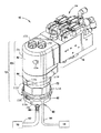
次に図1を参照すると、濃厚相ポンプ及びマニホールドのアセンブリ10が、濃厚相ポンプ12及びマニホールド14を含む。濃厚相ポンプ12は、本明細書において別段の規定がある場合を除き、例えば878号特許に概ね従って設計されるとともに動作することができるが、代替的には、必要に応じて多くの他の濃厚相ポンプ設計を用いることができる。本開示の目的から、濃厚相ポンプはコーティング材料供給部16から紛体コーティング材料を引き込んでスプレーガン18に押し出すものと理解すれば十分である。供給部16は、当該技術分野において既知であるか又は今後開発される任意の適した装置及び設計とすることができる。一般的な例は流動化床を有することができるホッパーであり、又は代替的に、紛体コーティング材料はボックス若しくは容器又は他の適した供給部から供給することができる。スプレーガン18はまた、濃厚相紛体流を受け取るとともにコーティング作業に適したスプレーパターンをつくり出すように任意の適した装置及び設計とすることができる。適した濃厚相スプレーガンの一例は、Nordson Corporation社(オハイオ州ウェストレイク所在)から入手可能なPRODIGY(商標)型スプレーガンである。代替的には、当該技術分野において既知であるか又は今後開発される多くの他の濃厚相スプレーガンを用いることができる。
Referring now to FIG. 1, a rich phase pump and
図1Aは、濃厚相ポンプ12、例えば878号特許に開示されているポンプの基本部品を単純化した概略形態で示す。第1の制御弁20を用いて、コーティング材料供給部16からポンプ12の入口22への紛体コーティング材料の流れを制御する。第2の制御弁24を用いて、ポンプ12の出口26からスプレーガン18への紛体コーティング材料の流れを制御する。ポンプ12は、ポンプチャンバー28を用いて更に実現することができる。ポンプチャンバー28はガス透過性フィルター30を有し、ガス透過性フィルター30は、このガス透過性フィルター30を囲む環34を有するフィルター圧力チャンバー32内に配置される。紛体コーティング材料は、第1の制御弁20を開くとともに負圧36(P−)を環34に印加することによってポンプチャンバー28に引き込まれる。紛体コーティング材料は、第1の制御弁20を閉じ、負圧P−を除去し、第2の制御弁24を開き、かつ、正圧38(P+)を環34に印加することによって、ポンプチャンバーから押し出される。このように、第1の制御弁20及び第2の制御弁24は、正圧P+及び負圧P−の印加に応じて互いに位相を異にして動作する。本明細書における例示的な実施形態では、制御弁20、24はそれぞれ、空気圧ピンチ弁の形態で実現することができる。
FIG. 1A shows, in simplified schematic form, the basic components of a
878号特許に記載されているようなポンプ12の場合、紛体コーティング材料は、ガス透過性フィルター30の一方の端30aに対して流出入する。したがって、第1の紛体流Yブロック40を用いて、制御弁20、24に対して入口紛体流分岐44及び出口紛体流分岐46を提供する。
In the case of the
ピンチ弁20、24は、以下で記載されるような弾性材を含むことができ、その自然な弛緩状態では開位置にある。ピンチ弁と連結したピンチ弁圧力チャンバー43に正圧が印加されると、ピンチ弁ボディに作用する外圧が弁を圧縮するか又は締め付けて弁を閉じる。例示的な実施形態では、圧力が解放される(圧力チャンバーを通気して圧力を解放することができる)と、ピンチ弁ボディの自然な弾性特性に起因してピンチ弁が開く。代替的には、負圧を任意選択的に圧力チャンバー43に印加してピンチ弁を開位置に戻すことに更に役立たせてもよい。
The
制御弁20、24が878号特許に記載されているような空気圧ピンチ弁の形態で実現される場合、各ピンチ弁は、ピンチ弁ボディ(54)内のそれぞれのピンチ弁圧力チャンバー43内に配置される。これにより、ピンチ弁を開閉するのにピンチ弁圧力チャンバー43に印加される正圧45及び任意選択的には負圧47の使用が可能になる。なお、任意選択的には、各ピンチ弁20、24は、各ピンチ弁を動作させるのにその関連したピンチ弁圧力チャンバー43にそれ自身が別個に制御される圧力を有することができる。ピンチ弁圧力チャンバーに圧力を印加するために、圧力通路内に第1の障壁部材すなわち障壁フィルター42を用いることができる。障壁部材は、紛体コーティング材料がマニホールド14内の圧力源又は周囲環境に引き戻される、すなわち吹き戻されることを防止するように機能する。障壁部材の一例は、空気を通すが紛体コーティング材料を阻止する多孔性フィルターである。商用に用いられる障壁フィルター42は、第1のYブロック40内に配置される。各ピンチ弁は、各ピンチ弁が個別に制御される実施形態に関して関連した障壁部材42を有することができる。マニホールド14は、ピンチ弁圧力チャンバー43に印加される圧力に関するタイミング及び供給を提供する。
If the
また、ポンプ12から連続的な紛体流排出を供給するために、ポンプ12は任意選択的に、それぞれが自身の一対の制御弁20/20’、24/24’を有する2つのポンプチャンバー28、28’(2つのチャンバーポンプの同様の部品を示すのにプライム記号’を用いる)を有することができる。したがって、通常の濃厚相ポンプは、2つのガス透過性フィルター30、30’及び4つの制御弁20/20’、24/24’及び4つの障壁フィルター42、42’を有することができる。第1のYブロック40には、4つの紛体流分岐44/44’及び46/46’を設けることができる。第2のポンプチャンバー28’を用いる結果、第2のYブロック48も用いられることになるが、その理由は、第1のポンプチャンバー28が供給部16から紛体を引き込むにつれ、第2のポンプチャンバー28’がスプレーガン18に紛体を押し出し、また逆に、第2のポンプチャンバー28’がスプレーガン18に紛体を押し出すにつれ、第1のポンプチャンバー28が供給部16から紛体を引き込むからである。したがって、第2のYブロック48は、供給部16とスプレーガン18と制御弁20/20’、24/24’との間に紛体流分岐50、50’及び52/52’を設けるように配置される。878号特許では、制御弁20/20’、24/24’は、弁ボディ54内に位置決めされ、弁ボディ54は、制御弁の動作の観察を可能にするとともに破損したピンチ弁を検出するように透明であるものとすることができる。ピンチ弁が破損した場合、紛体がピンチ弁ハウジング72内に漏出し、これにより、ピンチ弁又はピンチ弁ハウジング72を新しいピンチ弁と変えるよう作業者に知らせる。
Also, to provide continuous powder flow discharge from the
紛体コーティングシステムは多くの場合、多くの異なるタイプ及び色の紛体コーティング材料を使用し、紛体コーティング材料のタイプ又は色を替える場合、ポンプ12を清掃せねばならない。清掃作業の一環に、ポンプチャンバー28、28’、及び紛体流路の他の部分をパージすることがある。878号特許に記載されているパージ選択肢のうちの1つは、ガス透過性フィルター30、30’の、開口端、すなわちパージ端30b/30b’にパージガス56を加えることであり、パージ端30b/30b’は、ガス透過性フィルター30、30’の単一の入口/出口端30a、30a’に対向する。パージタイミング及び圧力源の制御は、マニホールド14内で行われる。
Powder coating systems often use many different types and colors of powder coating material, and the
ガス透過性フィルター30、30’とともにフィルター圧力チャンバー32、32’は、ポンプハウジング58内に配置される。878号特許に示されている実施形態では、ポンプハウジング58は、制御弁20/20’、24/24’及びポンプチャンバー28、28’を動作させるのに必要とされる種々の圧力信号を供給するために、マニホールド14と接触する。パージライン56が、ポンプハウジングの上部から逆止弁流路に合わせてポンプハウジング58に別個に取り付けられる。
Filter pressure chambers 32, 32 ′ along with gas
濃厚相ポンプ12の設計及び動作の更なる説明が878号特許に提示されているが、本発明を理解及び実施するには上記記載で十分である。
Although further description of the design and operation of the
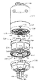
次に図2及び図3を参照すると、本開示に従った濃厚相送出ポンプ12の一実施形態が第1のハウジング60を有し、第1のハウジング60は、ポンプボディすなわちポンプハウジング62と、第1の紛体流ブロックすなわち上側紛体流ブロックすなわち紛体流ハウジング64とを含むことができる。第1のハウジング60は、第1のポンプチャンバー66及び第2のポンプチャンバー68を有し、これらのポンプチャンバーはそれぞれ、関連したそれぞれのガス透過性フィルター70を有する(図5も参照のこと)。ガス透過性フィルター70は大部分がポンプボディ62内に配置されるが、それぞれの下側部分は第1の紛体流ブロック64の中に延び得る。代替的には、ガス透過性フィルター70は、ポンプボディ62内に完全に配置されてもよい。
2 and 3, one embodiment of a dense
図4及び図5も参照すると、ピンチ弁ハウジング72は、それぞれが制御弁76を収納する4つのピンチ弁圧力チャンバー74(図4には2つしか示されていない)を有する透明の一体ボディであることが好ましいが、必ずしもそうである必要はない。なお、図3には、制御弁76がそれらのそれぞれのピンチ弁圧力チャンバー74内に部分的に設置されて示されている。各制御弁76は、適した材料、例えば天然ゴムから作製される可撓性の弾性ピンチ弁の形態で実現することができる。
Referring also to FIGS. 4 and 5, the
ポンプボディ62は、以下で更に記載される第1の逆止弁アセンブリ及び第2の逆止弁アセンブリ78を収納する。第1の紛体流ブロック64は、ボルト80によってポンプボディ62の底面に取り付けることができ、紛体チャンバー70aの入口紛体流路及び出口紛体流路として機能する紛体流分岐を有する。任意選択的には、ポンプボディ62と第1の紛体ブロック64との間の空気通路をシールするのにガスケット81を用いてもよい。
The
本明細書中、頂部、底部、上側及び下側への言及は、図面を見る場合の便宜上のものであり、使用の際、濃厚相ポンプ12がいずれかの特定の位置合わせにおいて向き付けられることを必要としないが、図面中に記載されているような縦又は直立の向きは共通である。
In this specification, references to the top, bottom, top and bottom are for convenience when viewing the drawings, and in use, the
878号特許におけるように、例示的な実施形態は2つのポンプチャンバー66、68を用いるため、第2の紛体流ブロックすなわち下側紛体流ブロックすなわち下側紛体流ハウジング82も用いる。第2の紛体流ブロック82は、ポンプ入口接続部88及びポンプ出口接続部90それぞれへの紛体流分岐84、86(第2の紛体流ブロック82内に、ポンプチャンバーに出入りする紛体流用の各ポンプチャンバー66、68用に2つずつ、総計4つの紛体流分岐がある)を提供する。ポンプ入口接続部88は、供給ホース92を介して紛体供給部16に接続可能であり、ポンプ出口接続部90は、ガンホース94によってスプレーガン18に接続可能である。
As in the 878 patent, the exemplary embodiment uses two
図2及び図4を参照すると、上述した第1の概念の別の実施形態が示されている。初めに、ピンチ弁76は摩耗部品(item)と考えることができ、このことは、ピンチ弁の繰り返される屈曲に起因して、ピンチ弁76が経時にわたって弱化又は摩耗又は破損する傾向があり、交換する必要性があることを意味することに留意すべきである。また、障壁フィルター96を、従来設計においてなされているように上側Yブロック40内にではなく、ピンチ弁ハウジング72内に配置するように移動させている。障壁フィルター96もまた摩耗部品であり、その理由は、障壁フィルター96は経時にわたり、紛体によって詰まるか若しくは閉塞するか、又は、少なくとも多孔性が低減するからである。ピンチ弁76を有するピンチ弁ハウジング72内に障壁フィルター96を配置することによって、障壁フィルター96を交換するのにより容易なアクセスが提供される。ピンチ弁76及び障壁フィルター96は本明細書において、交換可能な部品(図3の214)の例として言及されるが、その理由は、フィルター96は経時にわたって摩耗する傾向があり、ポンプ全体を引き続き使用することができるように整備される場合があるからである。他のポンプ設計は、更なる又は異なる交換可能な部品を使用することができる。
Referring to FIGS. 2 and 4, another embodiment of the first concept described above is shown. Initially, the
ピンチ弁ハウジング72内の交換可能な部品(214)への保守整備アクセスを単純化し、それにより、濃厚相ポンプ12の修繕、メンテナンス及びダウンタイムを低減するために、単一の解放可能な締結具98を用いて第2の紛体流ブロック82及びピンチ弁ハウジング72をポンプハウジング60に取り付ける。一実施形態、例えば、本明細書における図3では、第2の紛体流ブロック82及びピンチ弁ハウジング72は、単一の解放可能な締結具98を用いて第1の紛体流ブロック64に取り付けることができる。このようにして、単一の解放可能な締結具98を単に緩める、すなわち解放することによって、ピンチ弁ハウジング72をポンプハウジング60から取り外して交換可能な部品76、96(214)にアクセスすることができる。交換可能な部品(214)は、必要に応じて個別に交換することができる。代替的には、個々のアセンブリとして交換可能な部品を有するピンチ弁ハウジング72全体を、前に設置したピンチ弁ハウジング72の代わりに設置することができる。単一の解放可能な締結具98を用いることによって再組付けも単純化される。
A single releasable fastener to simplify maintenance access to replaceable parts (214) in
一実施形態では、単一の解放可能な締結具98は、端ねじボルト(end threaded bolt)の形態で実現することができるが、代替的には、多くの他のタイプの解放可能な締結具を用いることができる。ピンチ弁ハウジング72を組み付けるのに、また、通常の定期メンテナンス及び修繕を行うことができるようにピンチ弁ハウジング72を分解するのに単一の締結具98が用いられることを示すために「解放可能な」という語が用いられている。交換可能な部品(214)へのアクセス、及び/又はピンチ弁ハウジング72及び交換可能な部品(214)の個々のアセンブリの取外し及び交換のために、本明細書において、単一の解放可能な締結具98を解放する、すなわち緩めることに言及するが、その理由は、全ての修繕作業又はメンテナンス作業に対して締結具を完全に外すことを必要としないものとすることができるからである。しかしながら、必要であれば、単一の解放可能な締結具98を完全に抜くことができる。単一の解放可能な締結具の概念は、例えば、878号特許に記載されている濃厚相ポンプ又は既知の若しくは今後開発される他の濃厚相ポンプの場合の、本明細書における例示的な実施形態以外の濃厚相ポンプにおいて用いることができることに留意することが重要である。
In one embodiment, a single
図3、図4及び図4Aを参照すると、単一の解放可能な締結具98がマルチセクションコラム100の中央ボア100dを貫通している。ピンチ弁76の位置に対して、例えば濃厚相ポンプ12の中心長手方向軸Xに沿って、コラム100が中心に位置付けられることが好ましいが、必ずしもそうである必要はない。ピンチ弁76は例えば、ピンチ弁ハウジング72の中心長手方向軸の回りに均一に離間することができる。ピンチ弁ハウジング72の例示的な一実施形態の場合、ピンチ弁76は互いから約90度離して配置することができる。その場合、コラム100の中心位置により、締結具98を締め付ける際に圧縮力の均一な配分が促される。第1のコラムセクション100aが第2の紛体流ブロック82内に中心に位置決めされ、第2のコラムセクション100bがピンチ弁ハウジング72の中心を貫通し、第3のコラムセクション100cが第1の紛体流ブロック64内に中心に位置決めされる(図11及び図11Aも参照のこと)。このように、コラム100はセクション100a〜100cを有して実現することができ、各コラムセクションは、単一の解放可能な締結具98が貫通するか又は中を通る単一の中央開口を、関連したボディ内に有する。例えば、ピンチ弁ハウジング72は、ピンチ弁ハウジング72の中を完全に延びるとともに単一の解放可能な締結具に対して単一の中央開口を提供する中央コラムセクション100bを有する。
With reference to FIGS. 3, 4 and 4A, a single
コラム100は、第2の紛体流ブロック82(コラムセクション100a)、ピンチ弁ハウジング72(コラムセクション100b)及び第1の紛体流ブロック64(コラムセクション100c)の一部として一体形成することができる。3つのセクション100a〜100cは全て、互いと軸方向に位置合わせしており、そのため、単一の解放可能な締結具98が、中央ボア100dを貫通し、3つ全てのセクション100a〜100c内を通り、単一の解放可能な締結具98は、第1の紛体流ブロック64内のねじインサート102にねじ込むことができることができるねじ端部98aを有し得る。締結具98が締め付けられてねじインサート102に入ると、締結具98は引張下にあり、第2の紛体流ブロック82の上面(226)とともにピンチ弁ハウジング72の底面すなわち対向面(224)に押し当たり、また、ピンチ弁ハウジング72の上面(220)とともに第1の紛体流ブロック64の底面すなわち対向面(222)に押し当たり、これらの3つのピース82、72及び64を軸方向圧縮状態に保持する(図3も参照のこと)。ねじインサート102は、例えば真鍮等の金属を含むことができ、締結具98に電気的接地を提供するために金属ばね103と接触することができる。
The
ピンチ弁76はそれぞれ、以下で更に記載される2つの端フランジ(194)を有する。これらの端フランジは、単一の解放可能な締結具98が締め付けられると軸方向に圧縮されて気密なシールを形成し、そのため、ピンチ弁76を通って流れる紛体コーティング材料がピンチ弁の周囲を迂回することがなく、また、漏洩してピンチ弁ボディ72に対して出入りすることがない。その場合、単一の解放可能な締結具98は、ピンチ弁76がシールするのに十分に圧縮されるように十分に堅固であるとともにそのように十分に締め付けられることが有用である。単一の解放可能な締結具98は、十分なトルクを締結具98に加えられることを可能にするようにアレンレンチを受け入れるソケット98bを有することができる。
Each
過大なトルクがピンチ弁76及びフランジ(194)を圧潰及び破損させる可能性があるため、単一の解放可能な締結具98が過大なトルクにより過度に締め付けられることがないことも有用である。マルチセクションコラム100は、単一の解放可能な締結具98に過度のトルクが加えられることを防止する抑止機構として機能する。第1のコラムセクション100aは、第2のコラムセクション100bの下側遠位端106と接触する上側遠位端104を有し、第2のコラムセクション100bは、第3のコラムセクション100cの下側遠位端110と接触する上側遠位端108を有する。遠位端104、106、108、110は、連続的な支持コラム100内にひと続きの中央ボア100dを形成するように接触する。詳細には、遠位端104、106、108及び110は、ピンチ弁76の所定の圧縮又は制御された圧縮において完全に接触することができる。これらの3つ全てのコラムセクション100a〜100cが完全に接触状態になると、3つのボディ82、72及び64の更なる軸方向移動又は更なる圧縮が防止され、ピンチ弁76を更に圧縮する可能性も過度に圧縮する可能性もない。したがって、対向する接触面対、すなわち、ピンチ弁ハウジング72の上面(220)と第1の紛体流ブロック64の下面(222)との間の遠位端104/106と、ピンチ弁ハウジング72の下面(224)と第2の紛体流ブロック82の上面(226)との間の遠位端108/110は、単一の解放可能な締結具98の過度の締付け又は過度のトルクを防止する確実な抑止部として機能する。過度の締付け又は過度のトルクは、防止されなければ、ピンチ弁の端フランジ(194)を過度に圧縮するか又は破損させる可能性がある。
It is also useful that a single
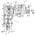
図5、図6及び図7を参照すると、上記のように、マニホールド14が濃厚相ポンプ12にパージ空気を供給する。用いることができるパージ方法のうちの1つは、加圧空気の流れを長手方向に方向付けて各ガス透過性フィルター70に通すことである。この文脈における「長手方向」という用語は、開口したパージ端30bからガス透過性フィルター70の開口した入口/出口端30a(図1Aを参照のこと)にかけてのパージ空気流路を示すのに用いられる。ポンプチャンバー66、68は双方とも同じであるため、2つのガス透過性フィルター70のうちの一方についての、パージ構成のうちの一方のみが記載されており、他方のポンプチャンバーは同じ構造及びパージ方法を必要に応じて同様に用いることができることが理解される。
Referring to FIGS. 5, 6, and 7, the manifold 14 supplies purge air to the
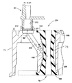
濃厚相ポンプ12は、一対のポンプチャンバー66、68を有する(図5〜図7にはポンプチャンバー68しか見えない)。ポンプチャンバー68は、ポンプボディ62の中に延びているボア112を有する。ボア112内には、逆止弁アセンブリ78及びガス透過性フィルター70が配置されている。例えばOリング等のシール114が、ガス透過性フィルター70のどちらかの端における圧力気密シールを提供し、そのため、ボア112の一部は、内部に配置されているガス透過性フィルター70の周囲に圧力チャンバー壁116を提供する、ボア112の壁の一部とともに圧力チャンバー32(図1A)の容積部としての役割を果たす。ガス透過性フィルター70は、例えば多孔質ポリエチレン等のガス多孔質材料を含む中空シリンダーとすることができる。この同じ材料を障壁フィルターディスク96に使用することもできる。したがって、中空シリンダーの中央容積部70aは紛体チャンバーとしての役割を果たし、この紛体チャンバーによって、紛体が濃厚相ポンプ12に引き込まれ、また、濃厚相ポンプ12から押し出される。ガス透過性フィルター70は、ガス透過性フィルター70の圧力チャンバーとしての役割を果たす環118を提供するように圧力チャンバー壁116内に嵌まる。環118は、上述したように、また、878号特許におけるように、正圧38(P+)及び負圧36(P−)(図1A)の源と流体連通しており(図5には示さず)、そのため、紛体コーティング材料は負圧下で紛体チャンバー70aに引き込まれ、正圧下で紛体チャンバー70aから押し出される。ガス透過性フィルター70の下端は、カウンターボア120内に収納することができ、カウンターボア120は、第1の紛体流ブロック64内にあるものとすることができ、紛体チャンバー70aが入口紛体流分岐122及び出口紛体流分岐124と流体連通するように位置合わせすることができ、入口紛体流分岐122及び出口紛体流分岐124がさらに、関連のピンチ弁76と流体連通する。各ガス透過性フィルター70の一部がポンプボディ62から延びていることによって、フィルター70は、ボルト80(図3)がポンプボディ62及び第1の紛体流ブロック64をともに保持していない場合に、設置及び取外しのために容易にアクセスされる。
The
ポンプボディ62は、ボルト126(図1及び図2)によってマニホールド14に取り付けられる。上記のように、マニホールド14は一部が空気マニホールドであり、空気マニホールドは、ポンプチャンバー66、68の圧力、パージ空気56(図1A)、及びピンチ弁76の圧力を含む種々の圧力信号及び種々の圧力条件を濃厚相ポンプ12に供給する。したがって、ポンプボディ62と、間に通る空気通路(図示せず)用のマニホールド14との間にシールされたインターフェース128が提供される。ポンプボディ62の後面130が第1の平面132を提供し、第1の平面132は、マニホールド14の前面136によって提供される第2の平面134と対向する。シールされたインターフェース128は、ボルト126が完全に締め付けられると、2つの対向する平面132、134間で圧縮される。シールされたインターフェース128は例えばガスケット138によって実現することができる。
The
図7を特に参照すると、逆止弁アセンブリ78は、ボア112の壁のねじ部分に螺着することができる逆止弁本体140を有する。ポンプボディ62内で逆止弁本体140の一部の周囲に設けられるOリング等のシール142により、シールされたチャンバー144が提供されている。パージ入口ボア146がポンプボディ62内に設けられている。空気通路148aが中を通っているカップラー148が、パージ入口ボア146の一端に設置され、マニホールド14内のパージ出口ボア150に挿入されている。パージ出口ボア150は、パージ空気源152からマニホールド14内の空気継手154を介してパージ空気を受け取る。パージ空気のタイミング及び制御は、マニホールド14内の弁及び制御部によって行われる。カップラー148は、ポンプボディ62とマニホールド14との間にインターフェース128を架け渡して、マニホールド14からポンプボディ62へのパージ空気用の圧力気密シール空気通路148aを提供する。例えばOリング等のシール156を、マニホールドのパージ出口ボア150におけるカップラー148をシールするのに用いることができる。
With particular reference to FIG. 7, the
パージ入口ボア146は、シールされたチャンバー144に開口しており、したがって、シールされたチャンバー144を介して逆止弁アセンブリ78へのパージ空気入口146aを提供する。マニホールドのパージ出口ボア150は、パージ空気入口146aと流体連通するマニホールド14から逆止弁アセンブリ78へのパージ空気出口150aを提供する。
The purge inlet bore 146 opens into the sealed
逆止弁栓158を逆止弁本体140に螺着させることができ、逆止弁栓158は中空の円筒形延在部160を有する。円筒形延在部160には1つ又は複数の貫通ポートすなわち貫通穴162が設けられており、貫通ポートすなわち貫通穴162は、シールされたチャンバー144と逆止弁本体144の内部キャビティ164との間に流体連通を確立する。逆止弁キャビティ164内には、ボール型逆止弁166が配置されている。逆止弁本体144の内部キャビティ164は、逆止弁が開いている場合にのみ、紛体チャンバー70aと流体連通する。逆止弁166はスリーブ状弁座部材168を有し、スリーブ状弁座部材168は、弁座168aと、弁部材170、例えばボールと、付勢部材172、例えばばねとを提供する。ばね172は、ボール170を付勢して弁座168aとシール係合させるように圧縮状態で弁部材170と弁座168との間に配置される。したがって、逆止弁166は、パージ空気圧がない状態でボール170が弁座168aに対して付勢されている、通常の閉鎖状態にある。
The
パージ空気が逆止弁166に供給されると、逆止弁は、パージ空気圧が逆止弁166のクラッキング圧力すなわち開放圧力を超えるまで閉じたままである。逆止弁166の開放圧力は、付勢部材172の強度を適切に選択することによって制御することができる。パージ空気圧が逆止弁166の開放圧力を超えると、弁部材170が弁座168aから離れ、パージ空気が逆止弁166を通って紛体チャンバー70aに流れ込んで紛体チャンバー70aから紛体をパージする。
As purge air is supplied to the
弁座ケージ168は任意選択的には、第2の弁座部材174を有し、第2の弁座部材174は、弁座ケージの下流端に第2の弁座174aを有する。この弁座は、パージ供給に過圧状態が生じた場合にパージ流を遮断するのに用いることができる。第2の弁座174は、例えばOリング等のシール176によって逆止弁本体140内でシールすることができる。
The
逆止弁166が開いた場合のパージ空気の流路が、矢印178によって概略的に表されている(図6及び図7を参照のこと)。パージ空気178は、パージ空気供給部152と流体連通するカップラー148からポンプボディ62に入る。パージ空気178は、シールされたチャンバー144に流れ込み、チャンバーがシールされているため、パージ空気は穴162側に押し上げられて穴162に通される。パージ空気圧が逆止弁166の開放圧力を超えると、ボール170が弁座168aから外れ、パージ空気178が逆止弁166の流れ軸に沿って流れ、紛体チャンバー70aに入ってその中を通る。図1Aから、パージ中、適切な弁が開いていることにより、パージ空気がスプレーガン18を完全に通ると同時にスプレーガンをパージし、また、紛体経路をパージして紛体供給部16に戻す必要があればそのようにすることができることに留意されたい。なお、パージ空気178は、紛体流用のポンプチャンバー68の入口及び出口の双方としての役割を果たす開口端182(図1Aにおける30aに対応する)に対向する、ガス透過性フィルター70の開口したパージ端180(図1Aにおける30bに対応する)において、ガス透過性フィルター70に入る。
The purge air flow path when the
878号特許等の従来の設計では、パージ空気は、ガス透過性フィルター30の同じ開口端30bを通ってガス透過性フィルター70に入る一方、逆止弁アセンブリの頂部に取り付けられている空気ホース及びコネクターを通って供給されるが、このことは、878号特許では、パージ空気は、逆止弁の流れ軸186及びガス透過性フィルター30の長手方向軸188と揃えられた、すなわちそれらの軸と同軸の逆止弁に供給されることを意味する。しかしながら、多くの濃厚相ポンプが紛体コーティングシステムにおいて使用される場合、パージ空気ホースの数が多くなり、これにより、システムがクラッター化し、扱いにくくなり、美的外観が下がることがわかっている。
In conventional designs such as the '878 patent, purge air enters the gas
図7に示されているように、パージ空気178は、ガス透過性フィルター70を通る紛体流の長手方向軸188の軸外で逆止弁アセンブリ68のパージ空気入口146aに入り、上記長手方向軸188は任意選択的に、逆止弁166の流れ軸186と揃えられている、すなわち同軸である。図示の実施形態は、パージ空気178が、逆止弁166の流れ方向軸186を横断するパージ流方向入口軸184に沿ってポンプボディ62に入ることを示す。逆止弁の流れ方向軸186は、ガス透過性フィルター70及び紛体チャンバー70aの長手方向軸188と揃えることができるが、そうである必要はない。
As shown in FIG. 7, the
パージ空気178は、ポンプボディ62に入り、ガス透過性フィルター70の長手方向軸188を横断するパージ流入口軸184に沿って逆止弁アセンブリ68に流れ込む。パージ空気178は次に、パージ空気が逆止弁166に入る際にパージ空気を90度だけ強制的に方向転換させる流路に沿って流れ、それによって、パージ空気流は逆止弁の流れ軸186と揃えられ、したがって、ガス透過性フィルター70及び紛体チャンバー70aの長手方向軸188とも揃えられる。
パージ空気の横断方向入口流の利点は、この横断方向入口流により、ポンプボディ62とマニホールド14との間の側面取付け構成部からパージ空気を供給しやすくなることである。これにより、逆止弁アセンブリ68とマニホールド14との間に接続されている頂面取付けされたパージホースの必要性が完全に排除される。パージ流入口軸184と、ガス透過性フィルター70及び紛体チャンバー70aの長手方向軸188との間の角度であると定義される、入口パージ空気流の軸外角度は、重大ではない。基本的に垂直な入口流(紛体チャンバー70aの長手方向軸188に対してパージ空気入口軸184が90度の軸外角度)が用いられるが、その理由は、そのような通路が幾つかの場合に加工がより容易である可能性があるからである。しかしながら、横断方向のパージ流入口についての軸外角度の選択は、特定の濃厚相ポンプ12及び/又はマニホールド14に関する必要に応じて選択することができる。パージ空気が横断方向に入ることの利益は、パージ流入口軸とガス透過性フィルター70を通る長手方向の流れ軸との横断関係によるものであり、このことは、逆止弁166が、特定の用途に合わせて、ガス透過性フィルターの長手方向軸188と揃えられる以外に向き付けられる必要がある場合に、そのようにすることができることを意味することに留意すべきである。そのような代替的な実施形態(図示せず)では、逆止弁166の向きは依然として、ガス透過性フィルター70の長手方向軸と揃えられるパージ空気の出口流を提供することが好ましいものであり得る。一例として、パージ空気流路の90度のターンは、逆止弁166自体内で起こり得る。
The advantage of the transverse inlet flow of purge air is that this transverse inlet flow facilitates the supply of purge air from the side mounted components between the
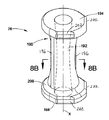
次に図8A及び図8Bを参照すると、ピンチ弁76が示されている。ピンチ弁76は、長手方向軸Xに沿って中央通路192が中を通っているピンチ弁本体190を有する。ピンチ弁76は、第1の端フランジ及び第2の端フランジ194を更に有し、これらの端フランジは同じサイズ及び形状とすることができる。端フランジ194を同じとすることによって、ピンチ弁76がピンチ弁ハウジング72内への第1の長手方向の向きに設置されようと、向きを変えて逆の長手方向の向きに設置されようと問題ではない。
8A and 8B,
ピンチ弁によっては、断面が円形ではなく(図8Bに示されているような)猫目形を有する中央通路192が設けられる。ピンチ弁76は、弁本体190の対向する両側面に沿って、直径方向に対向するとともに長手方向に延びる一対のリブ196を更に有することができる。これらのリブ196は、ピンチ弁本体190に局部化したスチフネスを与え、そのため、ピンチ弁が外部の正圧に晒されたときに、リブ196間のピンチ弁本体の部分198が、弁本体190に高い応力をかけることなくピンチ弁を閉じることを可能にするヒンジ点として働く。詳細には、ピンチ弁76は、リブ196が弁本体にかかる応力を低減させることにより、猫目形通路192の主面192aが空気圧力下でともに圧縮されることによって閉じる。ピンチ弁76が閉じると、弾性リブ196が引張状態になり、そのため、圧力を解放する、すなわち圧力を抜く際に、リブ196はピンチ弁76を開位置に戻すのに役立つ。なお、図8Bから、ピンチ弁本体192の形状は、横断面で見た場合、略楕円形の部分を有する。この形状により、ピンチ弁が閉じる際にヒンジ点として働く、楕円の外端によって、ピンチ弁を開閉させることが可能になる。
Some pinch valves provide a
端フランジ194はそれぞれ、平面図(図9)で見た場合、ピンチ弁ハウジング72内のピンチ弁圧力チャンバー74にピンチ弁76を組み入れるのに役立つ外周形状すなわち外形を有し得る。例えば、リブ196は、ピンチ弁圧力チャンバー74内に設けられている対応する長手方向スロット200の内部に嵌まることが好ましい(なお、図8Bでは、スロット200及び圧力チャンバー74は概略的に示されている)。リブ196をスロット200と位置合わせすることをより容易にさせるために、好ましい向きを示すための、2つのフラット202、又は、端フランジ194の他の認識可能な外周形状部が設けられる。その場合、端フランジ194はそれぞれ、非円形外周形状を有する。
Each
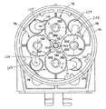
図9は、ピンチ弁ハウジング72内に設置されている4つ全てのピンチ弁76を示す。なお、フラット202は、ピンチ弁ボディ72の中心、例えば、中心コラム100の方を指し示す、組付者に対する(図9において矢印204によって表されているような)矢じり又は指標としての視覚的外観を形成する。これは、組付者がリブ196をピンチ弁圧力チャンバー74内の対応するスロット200内に位置付けるのに役立つ。したがって、フラット202は、組付者がピンチ弁を適切な向きに設置するのに役立てる上での位置合わせ表示として働く。フラット202は、関連した端フランジ194がピンチ弁ハウジング72内に径方向対称のシール面206(図10も参照のこと)を有するようにその端フランジ194の上面部分にのみ任意選択的に設けることができる。図9における破線Rは、リブ196とスロット200との位置合わせを示し、これらは他の状況では図面には示されない。
FIG. 9 shows all four
図10を参照すると、各ピンチ弁76は、ピンチ弁ハウジング72内のピンチ弁圧力チャンバーすなわちボア74(図1Aの43に対応する)内に配置されている。ピンチ弁圧力チャンバー74は、ピンチ弁本体190の楕円形状に概ね合致している。ピンチ弁端フランジ194は、ピンチ弁ハウジング72が第1の紛体流ブロック64と第2の紛体流ブロック82との間に組み付けられると、シール圧縮される。ピンチ弁圧力チャンバー74は、ピンチ弁76が開位置にあるか又は閉位置にあるかに応じて、空気圧通路208を介して圧力を受ける。ピンチ弁圧力チャンバー74は、内部に配置されているピンチ弁76と同じ長手方向軸Xを共有する。
Referring to FIG. 10, each pinch
878号特許では、ピンチ弁圧力チャンバーに開口する圧力通路は、ピンチ弁圧力チャンバーの長手方向軸から90度のところに形成されている。換言すれば、マニホールドからの空気圧が頂端からピンチ弁ハウジングに入り、その場合、圧力通路が最初にピンチ弁本体内へ下方に穿孔され、その後、ピンチ弁圧力チャンバーへのアクセスのためにクロス穿孔されている。本開示及び例示的な実施形態では、図10に示されているように、圧力通路208は、ピンチ弁圧力チャンバー74の長手方向軸に対して斜角で形成することができる。例えば、圧力通路208は、ピンチ弁圧力チャンバー74に対して導入斜角θを有する。斜角付き圧力通路208は例えば、入口ポート209からピンチ弁圧力チャンバー74まで延びることができる。斜角θは場合によっては、ピンチ弁ハウジング72内に形成することがより容易であるものとすることができ、また、圧力チャンバー74内への空気圧のより有効な導入を提供することができる。
In the '878 patent, the pressure passage opening into the pinch valve pressure chamber is formed 90 degrees from the longitudinal axis of the pinch valve pressure chamber. In other words, air pressure from the manifold enters the pinch valve housing from the top, where the pressure passage is first drilled down into the pinch valve body and then cross-drilled for access to the pinch valve pressure chamber. ing. In the present disclosure and exemplary embodiments, as shown in FIG. 10, the
ピンチ弁の不具合が生じた場合に空気圧源を紛体の侵入から保護するために、それぞれの障壁部材96、例えば、平坦なディスクの形態の障壁フィルター96が、ピンチ弁ハウジング72の上面220内に設けられているポート209内に配置される。ポート209は、空気圧流通路208と流体連通する。空気圧は、第1の紛体流ブロック64内の関連した空気圧分岐210を通って供給される。第1の紛体流ブロック64は、ピンチ弁76とガス透過性フィルター70との間に紛体流分岐を提供することに加え、マニホールド14からピンチ弁ハウジング72のピンチ弁圧力チャンバー74に正圧用の空気圧分岐も提供する。しかしながら、障壁部材が上側Yブロック内に配置されていた従来の設計とは対照的に、本開示における障壁部材96は、ピンチ弁ハウジング72内に配置することができ、そのため、単一の解放可能な締結具98が緩められると、アクセス可能であるとともに容易に交換可能である。例えばOリング等の適したシール212を用いて、第1の紛体流ブロック64の空気圧分岐210とピンチ弁ハウジング72の空気圧通路208との間に圧力気密シールを提供することができる。したがって、ピンチ弁76及び障壁フィルターディスク96並びにシール212は、ピンチ弁ハウジング72が第1の紛体流ブロック64から分離した場合に容易にアクセス可能である交換可能な部品214(図3)の例である。交換可能な部品214は通常、経時にわたって摩耗する部品であり、濃厚相ポンプ12の繰り返し動作により、修繕作業の際に又は定期メンテナンス時に交換される必要がある。
Each
図8C及び図8D及び図9Aを参照すると、別の実施形態のピンチ弁250が示されている。ピンチ弁250は、中央通路254が中を通っている概ね円筒形の本体252を有する。図8A及び図8Bの実施形態におけるように、中央通路254は非円形の断面形状を有し得るがその必要はなく、例えば、形状は猫目形のようであってもよく、また、ピンチ弁本体は横断面が楕円形状を有していてもよい。ピンチ弁250はまた、直径方向に対向したリブ256を有することができ、端フランジ面(278)の描線256aは、リブ256を直径かつ方向性の向きに指し示すように示されている。
Referring to FIGS. 8C and 8D and 9A, another
ピンチ弁250とピンチ弁76との第1の相違点は、上端フランジ258及び下端フランジ260が互いから径方向にずれていることである。以下で更に説明されるように、この径方向のずれは、ピンチ弁圧力チャンバー内の、リブ256を収納するスロットの位置に対応するように提供されている。参照のため、図面は、上端フランジ258の第1の位置合わせ軸262と下端フランジ260の第2の位置合わせ軸264とを示す(図8Dから最もよく理解される)。ピンチ弁250は依然として、図8Cの向きに設置することができるか、又は下端フランジ260に関して裏返すことができるという点で、反転可能であるものとすることができる。位置合わせ軸262、264は、それぞれの端フランジ258、260の最外の径方向範囲に関する。図8A及び図8Bの端フランジ194は、例えば878号特許のピンチ弁とは対照的に非円形であることに留意されたい。端フランジ258、260もまた非円形であり、図8Dに最もよく見られるようによりはっきりと規定された指標外形を有する。端フランジ258、260は、互いから径方向にずれているが、別様には、同じ形状、すなわち合致する形状であってもよく、そのため、ピンチ弁250は、第1の長手方向の向きに設置することができるか、又は、裏返して逆の長手方向の向きに設置することができる。
The first difference between the
ピンチ弁250に関して、各端フランジ258、260の円周部分266、268の半分以上は依然として円形とすることができるが、2つの直線部分270、272が、よりはっきりと規定された地点すなわち指標尖端274に合流しており、よりはっきりと規定された地点すなわち指標尖端274は各端フランジ258、260の径方向最外径範囲を定めている。各端フランジ258、260は、平面で見た場合、ピンチ弁ハウジングに組み入れる際にピンチ弁250を位置合わせする、より視覚的に知覚可能な方向すなわち向き表示を提供し、それによって、ピンチ弁250は、ピンチ弁ハウジング72の中心の方、例えば、径方向にコラム100の方を「指し示す」。別の又は更なる代替形態として、位置合わせ表示、例えば、任意選択的な方向矢印276を、端フランジ258、260の外面278上に設けることができる。方向矢印276は、必要に応じて、ピンチ弁本体252内に成形することも別様に設けることもできる。なお、方向矢印276は、指標尖端274と方向が位置合せされている。
With respect to the
例示的な一実施形態では、位置合わせ軸262、264は、平面で見た場合に端フランジ258、260間の径方向にずれた挟み角度αを示す。さらに、位置合わせ軸262、264はまた、各指標尖端274とリブ位置合わせ方向軸256aとの間の径方向にずれた挟み角度βを示す。換言すれば、端フランジ258、260の位置合わせ外形は、互いからだけでなくリブ256からも径方向にずれている。
In one exemplary embodiment, the alignment axes 262, 264 exhibit a radially offset pinching angle α between the
上述したように、リブは、ピンチ弁250(又は図8A及び図8Bの実施形態における76)の一部として用いられる場合、ピンチ弁圧力チャンバーにおけるスロットと位置合わせされてスロット内に収納されることになる。図8B及び図9の実施形態では、スロット200は、ラインR(ラインRはリブの向きを示す)によって示されているように、各隣接するピンチ弁圧力チャンバー74の両側のスロット200に対して直角に形成されることに留意されたい。さらに、スロット200及びリブ196は、878号特許(正方形のピンチ弁ハウジングを開示している)においてなされていたのと同様に向き付けられるが、この結果、リブ196は、例えばピンチ弁ハウジング72がここで概ねコンパクトな円筒形状を有する場合に、圧力通路208が圧力チャンバー74に開口する場所すなわちエリア内で圧力通路208を部分的に塞ぐ。
As described above, when used as part of the pinch valve 250 (or 76 in the embodiment of FIGS. 8A and 8B), the rib is aligned with the slot in the pinch valve pressure chamber and housed within the slot. become. In the embodiment of FIGS. 8B and 9, the
図9A及び図9Bを参照すると、ピンチ弁ハウジング72の代替的な実施形態では、ピンチ弁ハウジング290に、ピンチ弁リブ256を収納するスロット292が設けられている。スロット292は、圧力通路208が圧力チャンバー74に開口する場所すなわちエリアに対して或る角度だけ径方向にずれており、そのため、リブ256は圧力チャンバー74を加圧することの妨げとならない。一例として、スロット292は、圧力通路208が圧力チャンバー74に開口する場所から約37度だけ回転することができる。これにより、圧力通路208がピンチ弁圧力チャンバー74に開口する場所からリブ256が逸れる。このことはピンチ弁を圧縮させて閉じるのに役立つため、圧力通路208は、リブ196とヒンジ198との間にある、ピンチ弁本体のより平坦な部分に面することが好ましいが、必ずしもそうである必要はない。これは図9Bから最もよく理解される。なお、リブ256と、圧力チャンバー75への圧力通路208の開口との間で径方向にずれている角度は、ピンチ弁ハウジング72の形状、設計、寸法等、及び、ピンチ弁250の設計、特に楕円形部分の形状に応じて決まる。したがって、37度は、リブ256によって塞がれる向きには圧力通路208が圧力チャンバー74に開口しないことを確実にする径方向のずれの一例にすぎない。さらに、リブ256と、圧力チャンバー74への圧力通路208の開口との間でのこの径方向のずれにより、ヒンジ位置198(図9B)に面する圧力チャンバー74には圧力チャンバー208が開口しないことが確実になるが、その理由は、圧力チャンバー208がそのように開口した場合、ピンチ弁が閉位置にくると、ピンチ弁ヒンジエリア198が圧力通路208を塞ぐ可能性があり、圧力通路208が通気されずピンチ弁を再び開くことがない可能性がある。
Referring to FIGS. 9A and 9B, in an alternative embodiment of the
圧力通路208は、上述したようにピンチ弁圧力チャンバー74に対して導入斜角θで形成することができることにも留意すべきである。
It should also be noted that the
しかしながら、圧力通路208に対するリブスロット292の角度が径方向にずれている結果、図8Aの実施形態におけるように依然として同一に形状決めされているとともに径方向に位置合わせされている2つの端フランジ194を用いるピンチ弁76は、異形端フランジ(異形端フランジはピンチ弁ハウジング72の中心を「指し示す」ことが望まれる)を用いる正確な方向表示を提供しない。したがって、各端フランジ258、260に関して、例示的な実施形態では53度とすることができる挟み角度βだけ、リブ256の中心線に対して非円形端フランジの方向軸262、264が径方向にずらされる。なお、この角度は、リブ256と、圧力チャンバー74への圧力通路208の開口との間の径方向にずれた角度によって規定される。この結果、端フランジ258、260は、図8Dのように平面で見た場合、互いに対して74度の挟み角度αで互いから径方向にずれている。換言すれば、圧力チャンバー74の向き(ピンチ弁リブを二分する平面から測定した場合)は、ピンチ弁ハウジング72の中心長手方向軸回りに回転する。図9A及び図9Bの例示的な実施形態では、水平面(図9A及び図9Bに示されているように上から見た場合)からの角度は、角度βが53度である場合、37度と53度とに交互に変わる。ピンチ弁250は、リブ256が圧力チャンバー74のスロット292内に係止することによって圧力チャンバー74内に設置される必要があるため、ピンチ弁250の向きは、関連した圧力チャンバー292の向きによって変えられる(driven)。したがって、端フランジ258、260は、挟み角度αだけ互いから径方向にずれていることで、アセンブリを図9Aにおけるように上から見た場合に、ピンチ弁が常に、(設置される際のピンチ弁の長手方向の向きに関係なく)ピンチ弁ハウジング72の中心の方を指し示す涙滴状尖端すなわち指標尖端274によって正確に設置されることが確実になる。両方の長手方向の向きに設置可能なピンチ弁250を有することが望まれる場合、角度βの選択により角度αが決まる。また、角度βの選択は、圧力通路208が圧力チャンバー74に開口する場所並びにピンチ弁250の形状及び設計等、ピンチ弁圧力チャンバー74を加圧する特定のニーズに基づいて行うことができる。したがって、α及びβの例示的な値、並びに、リブ256と、圧力チャンバー74に開口する圧力通路208との間の径方向にずれた角度は、特定のピンチ弁ハウジングの特定の幾何学形状に基づいて選択することができる。
However, as a result of the radial misalignment of the
単一の解放可能な締結具98(図3)を緩めると、ピンチ弁ハウジング72が第1の紛体流ブロック64から分離されることで、ピンチ弁76及び障壁フィルターディスク96及びOリング212等の交換可能な部品214にアクセスすることができる。これらの交換可能な部品は、濃厚相ポンプ12を更に分解することがいっさいなく交換することができるが、任意選択的には、単一の解放可能な締結具98を外すと、ピンチ弁ハウジング72もまた、第2の紛体流ブロック82から分離することができる。この分離は、例えば、ピンチ弁ハウジング72全体を異なるピンチ弁ハウジング72と取り換える又は交換することになる場合に行うことができる。例えば、状況によっては、同じピンチ弁ハウジング72内の交換可能な部品214を交換するのに時間をかけるよりもむしろ、異なるセットの交換可能な部品214が既に設置されている別のピンチ弁ハウジングとピンチ弁ハウジング72を単に交換することがより迅速である場合がある。これにより、濃厚相ポンプ12のダウンタイムを更に減らすことができ、交換したピンチ弁ハウジングによりラインを一新することが可能になる。いずれの技術に関しても、ピンチ弁ハウジング72は、濃厚相ポンプ12の通常動作時に濃厚相ポンプ12に接続されているいかなるホースも取り外す必要なく、交換可能な部品214及び/又はピンチ弁ハウジング72自体を交換するのに役立つように容易にアクセスすることができることに留意されたい。例えば、ピンチ弁ハウジング72は、供給ホース92又はガンホース94を第2の紛体流ブロック82から取り外すことなく(図1)、又は、878号特許のタイプのパージ接続が用いられる実施形態では、パージ空気ホースを逆止弁から取り外すことなく、保守整備することができる。
When the single releasable fastener 98 (FIG. 3) is loosened, the
1つ又は複数の交換可能な部品、例えば、ピンチ弁76又は障壁部材96又はシール212を交換する例示的な一方法は、第1の紛体流ブロック64とピンチ弁ハウジング72と第2の紛体流ブロック82との間の軸方向圧縮を解放するように単一の解放可能な締結具98を緩めるステップを含む。第1のハウジング60(図1)をマニホールド14に取り付けたままにすることが望まれる場合、そのようにすることができる。上述のように、第1の紛体流ブロック64は、複数のボルト等の締結具80を用いてポンプボディ62に取り付けることができる。このようにして、ピンチ弁ハウジング72は、第1の紛体流ブロック64をポンプボディ62から分離することなく、又はポンプボディ62をマニホールド14から分離することなく保守整備することができる。
One exemplary method of replacing one or more replaceable parts, such as the
単一の解放可能な締結具98を緩め、ねじインサート102(図4)から解放した後、ピンチ弁ハウジング72を第1の紛体流ブロック64から軸方向に引き離す、すなわち分離させることができる(なお、例示的な実施形態は一般的な実施で行われるように縦向きで濃厚相ポンプ12を示しているが、そのような向きはポンプの動作に関して必須ではない)。ピンチ弁ハウジング72が第1の紛体流ブロック64から分離されると、ピンチ弁76、障壁部材96及びシール212のうちの1つ又は複数等の交換可能な部品214を異なる部品又は新しい部品と交換することができる。代替的には、ピンチ弁アセンブリハウジング72は、第2の紛体流ブロック82から更に分離させ、全体を交換してもよく、又は、場合によっては、スタンドアローン型アセンブリとしての第2の紛体流ブロック82からピンチ弁ハウジングも分離させることによって、交換可能な部品214を保守整備することをより容易にしてもよい。必要に応じて保守整備後に、濃厚相ポンプ12は、ピンチ弁ハウジング72を第1の紛体流ブロック64と嵌合させるとともに第2の紛体流ブロック82をピンチ弁ハウジング72と嵌合させ、次に単一の解放可能な締結具98を締め付けることによって、再び組み付けることができる。
After the single
図4、図11及び図11Aを参照すると、濃厚相ポンプ12を組み付けやすくするために、位置合わせ構造部を設けることができる。例えば、第1の紛体流ブロック64及び第2の紛体流ブロック82に対するピンチ弁ハウジング72の適切な径方向位置合わせにより、これらのボディ間に延びる種々の空気圧通路及び紛体流路が正確に位置合わせされるとともにシールされることが確実になる。適切な径方向位置合わせを確実にするように、第1の位置合わせ概念は取付け可能なボディにおけるキー溝要素215(図4)を意図する。キー溝要素215の1つの実施形態では、ピンチ弁ハウジング72には、ピンチ弁ハウジング72の外周に周方向に配置される1つ又は複数の延在部すなわちタブ216を設けることができる。これらのタブ216は、第1の紛体流ブロック64及び第2の紛体流ブロック82の外周に周方向に配置されている適合スロット218と嵌合する。ピンチ弁ハウジング72のポンプ対向面220の各タブ216aが、第1の紛体流ブロック64のピンチ弁対向面222の適合スロット218a内に収納される。同様に、ピンチ弁ハウジング72の反対側の対向面224の各タブ216bが、第2の紛体流ブロック82のピンチ弁対向面226の適合スロット218b内に収納される。
Referring to FIGS. 4, 11, and 11A, an alignment structure can be provided to facilitate assembly of the
嵌合タブ216及び適合スロット218は、ピンチ弁ハウジング72の外壁228に沿って僅かに径方向内側に配置することができ、そのため、キー溝要素215は、ピンチ弁ハウジング72が第1の紛体流ブロック64及び第2の紛体流ブロック82とともに組み付けられると包囲される。キー溝要素215は、外周に沿う以外の他の場所に位置付けられる必要がある場合にそのように位置付けることができ、また、任意の適した形状又は幾何学形状を有することができる。タブ216及び適合スロット218は、ピンチ弁ハウジング72の各面220、224のタブ216のうちの少なくとも1つ及びその適合スロット218を他とは異なるサイズ又は形状にさせることによって互いにキー溝を付けることができる。このようにして、ピンチ弁ハウジング72は、1つの径方向の向きにのみ第1の紛体流ブロック64及び第2の紛体流ブロック82に組み付けることができ、キー溝要素215はまた、ピンチ弁ハウジング72を1つの軸方向の向きにのみ組み付ける(例えば、第1の面220が第1の紛体流ブロック64とのみ組み付けられ、逆さには組み付けられない)ことができるように選択することができる。代替的には、反転可能なピンチ弁ハウジングに関して、キー溝要素215は、径方向の位置合わせを行うようにしか設計される必要がない。
The
キー溝要素215はまた、協働してピンチ弁ハウジング72と第1の紛体流ブロック64及び第2の紛体流ブロック82との相対回転を制限することが好ましいが、必須ではない。この制限は、例えば、組み付けられたキー溝要素215がピンチ弁ハウジング72と第1の紛体流ブロック64及び第2の紛体流ブロック82との相対回転を制限するようにタブ216と適合スロット218との寸法上の密着を行うことによって実現することができる。タブとスロットとの寸法上の密着が締まり嵌めに達するかどうかは、設計選択にかかわる問題である。寸法上の密着は、組み付けられたボディ間の相対回転を防止するのに十分であるが、組付け又は分解を不能にするほどきつくはないことが好ましい。これらの教示から、組み付けられたボディ72、64及び82間にキー溝接続及び位置合わせを提供する多くの他の方法が、当業者には容易に明らかであろう。
The
キー溝要素215は、必要に応じて幾つかの嵌合ボディに配置することができる。例えば、タブ216を第1の紛体流ブロック64及び第2の紛体流ブロック82に設けることができ、スロット218をピンチ弁ハウジング72に配置することができる。別の代替形態は、3つ全てのボディ72、64及び82が、取り付けられるボディの対向面の適合タブ及びスロットと協働するタブ及びスロットを有することができるというものである。
The
図1及び図2を参照すると、キー溝要素215は、第1の紛体流ブロック64及び第2の紛体流ブロック82に対して好ましくは単一の径方向位置に組み付けられるようにピンチ弁ハウジング72を制限する。異なる形状又はサイズのキー溝要素215は組付者にとって視覚的に区別することができるが、必ずしもそのような区別ができるとは限らない。単一の解放可能な締結具98を締め付ける前にこれらのボディの組み付けに更に役立たせるために、外部の位置合わせ表示230を設けることができる。ピンチ弁ハウジング72、第1の紛体流ブロック64及び第2の紛体流ブロック82のそれぞれは、隣接するボディと位置合わせさせる、正確な径方向位置合わせを示す、外部の位置合わせ表示230を有することができる。例えば、外部の位置合わせ表示は、ピンチ弁ハウジング72の外面234上の1つ又は複数の方向指標232の形態とすることができ、方向指標232は、これらのボディを径方向に位置合わせする際に第1の紛体流ブロック64の外面238及び第2の紛体流ブロック82の外面240上の方向指標236と位置合わせする。外部の位置合わせ表示230は、任意の適した形態及び外観を有することができる。例えば、外部の位置合わせ表示230は、外面234、238又は240上のエンボス加工された隆起面若しくはレリーフとすることができるか、又は、ラベル上に施されている、すなわちラベル上に印刷されているものとすることができるか、又は、必要に応じて他の適した技法を用いることができる。外部の位置合わせ表示230を用いて濃厚相ポンプ12の組付けに役立たせることができ、ポンプを組み付けて単一の解放可能な締結具98を締め付けた後、外部の位置合わせ表示230により、ピンチ弁ハウジング72が第1の紛体流ブロック64及び第2の紛体流ブロック82と適切かつ径方向に位置合わせされたことの視覚的な確認が提示される。
Referring to FIGS. 1 and 2, the
本発明の種々の態様、特徴及び概念を、例示的な実施形態における種々の組合せにおいて具現されるものとして本明細書において記載及び図示してきたが、これらの種々の態様、特徴及び概念は、多くの代替的な実施形態において、個々に、又はそれらの種々の組合せ及び部分的な組合せで実現することができる。本明細書において明確に除外されていない限り、そのような組合せ及び部分的な組合せは全て、本発明の範囲内にあることが意図される。さらにまた、代替的な材料、構造、構成、方法、装置等のような、本発明の種々の態様及び特徴に関する種々の代替的な実施形態を本明細書において記載することができるが、そのような記載は、現時点で既知であるか又は今後開発されるかにかかわらず、利用可能な代替的な実施形態の完全な又は網羅的な列挙であることは意図されない。当業者であれば、更なる実施形態が本明細書に明確に開示されていない場合であっても、そのような実施形態に種々の本発明の態様、概念又は特徴のうちの1つ又は複数を本発明の範囲内で容易に採用することができる。さらに、本発明の幾つかの特徴、概念又は態様を好ましい構成又は方法であるものとして本明細書に記載することができるとしても、そのような記載は、そのような特徴が必須又は必要であると明記されていない限りそうであることを示唆することは意図されない。さらにまた、例示的又は代表的な値及び範囲は、本発明を理解する上で役立たせるために記載され得るが、そのような値及び範囲は、限定的な意味で解釈されるべきではなく、臨界値又は臨界範囲であると明記されている場合に限りそのように意図される。さらに、幾つかの特徴及び態様及びそれらの組合せが特定の形態、適合、機能、構成又は方法を有するものとして本明細書に記載又は図示されることができるとしても、そのような記載は、そのような記載又は図示されている構成が必須又は必要であると明記されていない限りそうであることを示唆することは意図されない。当業者であれば、本明細書に記載されている実施形態及び発明に対する置換又は代替として既知であるか又は今後開発される、付加的かつ代替的な形態、機能、構成又は方法を容易に理解するであろう。 Although various aspects, features and concepts of the present invention have been described and illustrated herein as being embodied in various combinations in exemplary embodiments, many of these various aspects, features and concepts are In alternative embodiments, may be implemented individually or in various combinations and subcombinations thereof. All such combinations and subcombinations are intended to be within the scope of the invention, unless expressly excluded herein. Furthermore, although various alternative embodiments relating to various aspects and features of the present invention can be described herein, such as alternative materials, structures, configurations, methods, devices, etc., as such This description is not intended to be a complete or exhaustive list of available alternative embodiments, whether currently known or developed in the future. Those skilled in the art will recognize that such embodiments may include one or more of various aspects, concepts or features of the present invention, even if such embodiments are not explicitly disclosed herein. Can be easily adopted within the scope of the present invention. Further, although certain features, concepts or aspects of the invention may be described herein as being a preferred configuration or method, such a description is essential or necessary for such features. It is not intended to imply that unless it is explicitly stated. Furthermore, although exemplary or representative values and ranges may be set forth to aid in understanding the present invention, such values and ranges should not be construed in a limiting sense, It is intended to do so only if it is specified as a critical value or critical range. Further, even though some features and aspects and combinations thereof may be described or illustrated herein as having a particular form, adaptation, function, configuration or method, such a description is It is not intended to imply that such a description or illustrated configuration is so unless it is explicitly stated that it is essential or necessary. Those skilled in the art will readily understand additional and alternative forms, functions, configurations or methods that are known or will be developed in the future as replacements or alternatives to the embodiments and inventions described herein. Will do.
例示的な実施形態を参照しながら本発明を記載してきた。本明細書及び図面を一読及び理解すれば他者には変更及び変形が想起されるであろう。そのような変更及び変形は全て、添付の特許請求の範囲又はその均等物の範囲内にある限り含まれることが意図される。 The invention has been described with reference to exemplary embodiments. Modifications and variations will occur to others upon reading and understanding this specification and drawings. All such changes and modifications are intended to be included within the scope of the appended claims or their equivalents.
Claims (60)
第1のハウジングと、
前記第1のハウジング内に配置されるガス透過性フィルターと、
少なくとも1つのピンチ弁を収納するようになっているピンチ弁ハウジングと、
前記ピンチ弁ハウジングと前記第1のハウジングをともに取り付ける単一の解放可能な締結具と、
を備える、濃厚相紛体ポンプ。 A dense phase powder pump,
A first housing;
A gas permeable filter disposed in the first housing;
A pinch valve housing adapted to house at least one pinch valve;
A single releasable fastener for attaching the pinch valve housing and the first housing together;
A dense phase powder pump.
中央流路が中を通っている環状体と、
前記環状体の第1の端における第1の端フランジ及び前記環状体の対向端における第2の端フランジであって、各該第1の端フランジ及び該第2の端フランジは、前記環状体よりも大きな外径を有する、第1の端フランジ及び第2の端フランジと、
を備え、
前記第1の端フランジ及び前記第2の端フランジのうちの少なくとも一方の端フランジは、該ピンチ弁がピンチ弁ボディ内に設置される際に該ピンチ弁を位置合わせする異形外周を有する、ピンチ弁。 A pinch valve,
An annular body through which the central channel passes;
A first end flange at a first end of the annular body and a second end flange at an opposite end of the annular body, wherein each of the first end flange and the second end flange is the annular body. A first end flange and a second end flange having a larger outer diameter;
With
At least one end flange of the first end flange and the second end flange has a modified outer periphery that aligns the pinch valve when the pinch valve is installed in the pinch valve body. valve.
少なくとも1つの圧力チャンバーと、該圧力チャンバー内に配置されるガス透過性フィルターとを備えるポンプハウジングであって、前記ガス透過性部材は長手方向軸を有する、ポンプハウジングと、
前記圧力チャンバーと流体連通する正圧源及び前記圧力チャンバーと流体連通する負圧源であって、それによって、前記圧力チャンバーが負圧下にある場合に紛体を前記ガス透過性フィルターの第1の端に引き込み、前記圧力チャンバーが正圧下にある場合に紛体を前記第1の端を介して前記ガス透過性フィルターから押し出す、正圧源及び負圧源と、
前記ガス透過性部材の第2の端に動作可能に連結される逆止弁であって、それによって、該逆止弁が開いている場合にパージ空気が前記第2の端から前記第1の端へ軸方向に前記ガス透過性部材に流れ込む、逆止弁と、
前記ポンプハウジングへのパージ空気入口であって、パージ空気が、前記ガス透過性部材長手方向軸を横断するパージ空気軸に沿って前記ポンプハウジングに入り、該パージ空気入口は前記逆止弁の入口と流体連通する、パージ空気入口と、
を備える、濃厚相ポンプ。 A rich phase pump,
A pump housing comprising at least one pressure chamber and a gas permeable filter disposed in the pressure chamber, wherein the gas permeable member has a longitudinal axis;
A positive pressure source in fluid communication with the pressure chamber and a negative pressure source in fluid communication with the pressure chamber, whereby the powder is removed from the first end of the gas permeable filter when the pressure chamber is under negative pressure. A positive pressure source and a negative pressure source that pushes the powder out of the gas permeable filter through the first end when the pressure chamber is under positive pressure;
A check valve operably coupled to a second end of the gas permeable member, whereby purge air is passed from the second end to the first end when the check valve is open; A check valve that flows into the gas permeable member axially to the end;
A purge air inlet to the pump housing, wherein purge air enters the pump housing along a purge air axis transverse to the gas permeable member longitudinal axis, the purge air inlet being an inlet of the check valve A purge air inlet in fluid communication with the
A rich phase pump.
単一の解放可能な締結具を解放するステップであって、該単一の解放可能な締結具によって、ポンプハウジングに取り付けられているピンチ弁ハウジングを取り外すステップと、
前記ポンプハウジングとの取付けから前記ピンチ弁ハウジングを取り外すステップであって、前記ピンチ弁ハウジング内に配置されているピンチ弁へのアクセスを提供するステップと、
1)異なるピンチ弁と交換するように前記ピンチ弁、又は2)異なるピンチ弁ハウジングと交換するように前記ピンチ弁ハウジングのいずれかを取り外すステップと、
を含む方法。 A method of replacing a pinch valve arranged in a rich phase pump,
Releasing a single releasable fastener, wherein the single releasable fastener removes a pinch valve housing attached to the pump housing;
Removing the pinch valve housing from attachment with the pump housing, providing access to a pinch valve disposed within the pinch valve housing;
Removing either 1) the pinch valve for replacement with a different pinch valve, or 2) replacing the pinch valve housing for replacement with a different pinch valve housing;
Including methods.
第1のハウジングと、
前記第1のハウジング内に配置されるガス透過性フィルターと、
少なくとも1つの交換可能な部品を収納するようになっている第2のハウジングと、
前記第2のハウジング及び前記第1のハウジングをともに取り付ける単一の解放可能な締結具と、
を備える、濃厚相紛体ポンプ。 A dense phase powder pump,
A first housing;
A gas permeable filter disposed in the first housing;
A second housing adapted to house at least one replaceable part;
A single releasable fastener that attaches the second housing and the first housing together;
A dense phase powder pump.
中央流路が中を通っている環状体と、
前記環状体の第1の端における第1の端フランジ及び前記環状体の対向端における第2の端フランジと、
を備え、
前記第1の端フランジ及び前記第2の端フランジは、該ピンチ弁がピンチ弁ボディ内に設置される際に該ピンチ弁を位置合わせする異形外周を有し、前記第1の端フランジは、前記第2の端フランジから径方向にずれている、ピンチ弁。 A pinch valve,
An annular body through which the central channel passes;
A first end flange at a first end of the annular body and a second end flange at an opposite end of the annular body;
With
The first end flange and the second end flange have a deformed outer periphery that aligns the pinch valve when the pinch valve is installed in the pinch valve body, and the first end flange is A pinch valve that is radially offset from the second end flange.
中央流路が中を通っている環状体と、
前記環状体の第1の端における第1の端フランジ及び前記環状体の対向端における第2の端フランジと、
を備え、
前記第1の端フランジ及び前記第2の端フランジは、該ピンチ弁がピンチ弁ボディ内に設置される際に該ピンチ弁を位置合わせする非円形外周形状を有する、ピンチ弁。 A pinch valve,
An annular body through which the central channel passes;
A first end flange at a first end of the annular body and a second end flange at an opposite end of the annular body;
With
The first end flange and the second end flange have a non-circular outer peripheral shape that aligns the pinch valve when the pinch valve is installed in the pinch valve body.
少なくとも1つのピンチ弁圧力チャンバーを有するボディであって、前記ピンチ弁圧力チャンバーは長手方向軸Xを有する、ボディと、
入口ポートから前記ピンチ弁圧力チャンバーまで延びる圧力通路であって、前記長手方向軸Xに対して斜角θで前記ピンチ弁圧力チャンバーに開口する、圧力通路と、
を含む、ピンチ弁ハウジング。 A pinch valve housing,
A body having at least one pinch valve pressure chamber, the pinch valve pressure chamber having a longitudinal axis X;
A pressure passage extending from an inlet port to the pinch valve pressure chamber and opening into the pinch valve pressure chamber at an oblique angle θ with respect to the longitudinal axis X;
Including a pinch valve housing.
少なくとも1つの圧力チャンバーを有するボディと、
前記圧力チャンバー内に配置されるピンチ弁と、
を含み、
前記ピンチ弁は、それぞれが非円形外周形状を有する第1の端フランジ及び第2の端フランジを有する、ピンチ弁ハウジング。 A pinch valve housing,
A body having at least one pressure chamber;
A pinch valve disposed in the pressure chamber;
Including
The pinch valve housing has a first end flange and a second end flange each having a non-circular outer peripheral shape.
少なくとも1つの圧力チャンバーを有するボディと、
前記圧力チャンバー内に配置されるピンチ弁と、
前記圧力チャンバーと流体連通する入口ポートと、
前記入口ポート内に配置される障壁部材と、
を含む、ピンチ弁ハウジング。 A pinch valve housing,
A body having at least one pressure chamber;
A pinch valve disposed in the pressure chamber;
An inlet port in fluid communication with the pressure chamber;
A barrier member disposed within the inlet port;
Including a pinch valve housing.
中心長手方向軸を有するボディを備え、該ボディは、少なくとも第1の圧力チャンバー及び第2の圧力チャンバーを有し、該第1の圧力チャンバー及び該第2の圧力チャンバーのそれぞれは、非円形であり、前記第1の圧力チャンバーは、前記中心長手方向軸回りの第1の方向に向き付けられ、前記第2の圧力チャンバーは、前記中心長手方向軸回りの、前記第1の径方向とは異なる第2の方向に向き付けられる、ピンチ弁ハウジング。 A pinch valve housing,
A body having a central longitudinal axis, the body having at least a first pressure chamber and a second pressure chamber, each of the first pressure chamber and the second pressure chamber being non-circular. And the first pressure chamber is oriented in a first direction about the central longitudinal axis, and the second pressure chamber is the first radial direction about the central longitudinal axis. A pinch valve housing oriented in a different second direction.
長手方向に中を延びるとともに締結具を収納するようになっている中央ボアを有するボディを含む、ピンチ弁ハウジング。 A pinch valve housing,
A pinch valve housing including a body having a central bore extending longitudinally therein and adapted to receive a fastener.
少なくとも1つの圧力チャンバーを有するボディと、
前記圧力チャンバー内に配置されるピンチ弁と、
を含み、
前記ピンチ弁は、前記ボディにおける前記ピンチ弁の向きを示す表示を有する、ピンチ弁ハウジング。 A pinch valve housing,
A body having at least one pressure chamber;
A pinch valve disposed in the pressure chamber;
Including
The pinch valve is a pinch valve housing having an indication indicating the orientation of the pinch valve in the body.
Applications Claiming Priority (2)
| Application Number | Priority Date | Filing Date | Title |
|---|---|---|---|
| US13/837,169 US20140261739A1 (en) | 2013-03-15 | 2013-03-15 | Dense phase pump with easily replaceable components |
| US13/837,169 | 2013-03-15 |
Related Parent Applications (1)
| Application Number | Title | Priority Date | Filing Date |
|---|---|---|---|
| JP2014051544A Division JP6448912B2 (en) | 2013-03-15 | 2014-03-14 | Rich phase pump with easily replaceable parts |
Related Child Applications (1)
| Application Number | Title | Priority Date | Filing Date |
|---|---|---|---|
| JP2020075905A Division JP7101209B2 (en) | 2013-03-15 | 2020-04-22 | Concentrated phase pump with easily replaceable parts |
Publications (1)
| Publication Number | Publication Date |
|---|---|
| JP2018155251A true JP2018155251A (en) | 2018-10-04 |
Family
ID=50277076
Family Applications (3)
| Application Number | Title | Priority Date | Filing Date |
|---|---|---|---|
| JP2014051544A Active JP6448912B2 (en) | 2013-03-15 | 2014-03-14 | Rich phase pump with easily replaceable parts |
| JP2018114121A Pending JP2018155251A (en) | 2013-03-15 | 2018-06-15 | Dense phase pump having part replaceable easily |
| JP2020075905A Active JP7101209B2 (en) | 2013-03-15 | 2020-04-22 | Concentrated phase pump with easily replaceable parts |
Family Applications Before (1)
| Application Number | Title | Priority Date | Filing Date |
|---|---|---|---|
| JP2014051544A Active JP6448912B2 (en) | 2013-03-15 | 2014-03-14 | Rich phase pump with easily replaceable parts |
Family Applications After (1)
| Application Number | Title | Priority Date | Filing Date |
|---|---|---|---|
| JP2020075905A Active JP7101209B2 (en) | 2013-03-15 | 2020-04-22 | Concentrated phase pump with easily replaceable parts |
Country Status (5)
| Country | Link |
|---|---|
| US (4) | US20140261739A1 (en) |
| EP (3) | EP2777821B2 (en) |
| JP (3) | JP6448912B2 (en) |
| CN (2) | CN107716148B (en) |
| DE (1) | DE202014011108U1 (en) |
Families Citing this family (13)
| Publication number | Priority date | Publication date | Assignee | Title |
|---|---|---|---|---|
| US20140261739A1 (en) | 2013-03-15 | 2014-09-18 | Nordson Corporation | Dense phase pump with easily replaceable components |
| USD771719S1 (en) * | 2014-12-17 | 2016-11-15 | Graco Minnesota Inc. | Plural component proportioner |
| USD784414S1 (en) * | 2015-10-20 | 2017-04-18 | Forefront Product Design, Llc | Portable pump assembly |
| US10711788B2 (en) | 2015-12-17 | 2020-07-14 | Wayne/Scott Fetzer Company | Integrated sump pump controller with status notifications |
| IT201600071110A1 (en) * | 2016-07-07 | 2018-01-07 | Verne Tech S R L | SLEEVE VALVE. |
| US10378661B2 (en) | 2016-11-08 | 2019-08-13 | Mueller International, Llc | Valve body with integral bypass |
| KR102343575B1 (en) * | 2017-01-17 | 2021-12-27 | 마이크로플루이딕스 인터내셔날 코퍼레이션 | Apparatus and method using high pressure double check valve |
| US10661332B2 (en) | 2017-04-10 | 2020-05-26 | Mueller International, Llc | Monolithic bypass |
| USD893552S1 (en) * | 2017-06-21 | 2020-08-18 | Wayne/Scott Fetzer Company | Pump components |
| USD886157S1 (en) * | 2017-09-29 | 2020-06-02 | Fluke Corporation | High pressure manual pump with detachable manifold and high pressure pneumatic calibration manifold |
| USD890211S1 (en) | 2018-01-11 | 2020-07-14 | Wayne/Scott Fetzer Company | Pump components |
| USD870153S1 (en) * | 2018-03-15 | 2019-12-17 | Kelai Pumps (Ningbo) Co., Ltd | Effluent pump |
| US11339688B2 (en) | 2020-01-29 | 2022-05-24 | Borgwarner, Inc. | Variable camshaft timing valve assembly |
Citations (7)
| Publication number | Priority date | Publication date | Assignee | Title |
|---|---|---|---|---|
| US4108418A (en) * | 1977-01-19 | 1978-08-22 | Cla-Val Co. | Fluid operated pinch valve |
| US4373877A (en) * | 1980-09-15 | 1983-02-15 | The Bendix Corporation | Pump with rotatable reservoir casing and index means |
| JPS58189862U (en) * | 1982-06-11 | 1983-12-16 | 株式会社テイエルブイ | Valve using flexible valve body |
| US4742593A (en) * | 1985-09-12 | 1988-05-10 | Coxwold (Proprietary) Ltd. | Valve member for water interruption pool cleaner |
| JP2007512947A (en) * | 2003-11-24 | 2007-05-24 | ノードソン コーポレーション | Concentrated phase pump for dry particulate materials |
| DE102007006764B3 (en) * | 2007-02-12 | 2008-04-30 | Festo Ag & Co. | Squeeze valve for use in dental instrument, has support pipe provided with shell units with cross section, where shell units are arranged in direction in valve unit about wall with respect to axis of valve unit in radial direction |
| DE202008015865U1 (en) * | 2008-12-03 | 2009-02-19 | Festo Ag & Co. Kg | Valve member for a pinch valve and thus equipped pinch valve |
Family Cites Families (97)
| Publication number | Priority date | Publication date | Assignee | Title |
|---|---|---|---|---|
| US456818A (en) | 1891-07-28 | herring-ton | ||
| US276299A (en) | 1883-04-24 | stabb | ||
| US424161A (en) | 1890-03-25 | Hay-press | ||
| US318412A (en) | 1885-05-19 | Implement for obimping shells | ||
| US348922A (en) | 1886-09-07 | Spoke-fitting machine | ||
| US464063A (en) | 1891-12-01 | Electric motor | ||
| US237312A (en) | 1881-02-01 | noyes | ||
| US403049A (en) | 1889-05-07 | Spike-blank bar | ||
| US486061A (en) | 1892-11-08 | Half to william w | ||
| US523251A (en) | 1894-07-17 | The nor | ||
| US2627874A (en) * | 1945-09-20 | 1953-02-10 | Richard S Johnson | Hydraulically operated reinforced collapsible valve |
| US2606500A (en) * | 1946-06-24 | 1952-08-12 | Benjamin F Schmidt | Fluid actuated double-acting submersible pump |
| US2995335A (en) * | 1957-04-26 | 1961-08-08 | Spiros G Raftis | Collapsible valve apparatus |
| US3047008A (en) * | 1957-05-24 | 1962-07-31 | J R Clarkson Company | Valve |
| US3007416A (en) * | 1958-08-13 | 1961-11-07 | Gen Dynamics Corp | Pump for cellular fluid such as blood and the like |
| US3064997A (en) * | 1958-10-13 | 1962-11-20 | Karlsson Gustaf Valfrid | Socket pipe |
| US3260285A (en) | 1963-08-05 | 1966-07-12 | Clarence W Vogt | Apparatus and method for filling containers for pulverulent material |
| US3490732A (en) * | 1967-02-24 | 1970-01-20 | Union Carbide Corp | Pressure programmed check valve |
| US3895631A (en) * | 1974-02-04 | 1975-07-22 | Alza Corp | Liquid infusion unit |
| NL160370C (en) | 1974-03-14 | 1979-10-15 | Ocean Bv | MEMBRANE VALVE WITH A CORE BODY FITTED WITH RADIAL LONG RIBS. |
| USD244943S (en) | 1975-10-28 | 1977-07-05 | Xerox Corporation | Film reel |
| ES457022A1 (en) * | 1977-03-21 | 1978-03-01 | Schott Malo Carlos | Sealing valve for sludge scavenging system |
| US4268005A (en) | 1978-12-08 | 1981-05-19 | Red Valve Company, Inc. | Pinch valve |
| US4312528A (en) | 1979-11-07 | 1982-01-26 | Plc Engineering Company Limited | Panic bolt assembly |
| US4372528A (en) | 1981-07-06 | 1983-02-08 | Red Valve Co., Inc. | Pinch valve sleeve |
| USD276299S (en) | 1982-04-12 | 1984-11-13 | Reardon Patrick O | Water bed air bleeder |
| DE3302804C2 (en) * | 1983-01-28 | 1985-03-14 | Fresenius AG, 6380 Bad Homburg | Device for removing water from blood |
| AU90671S (en) | 1983-05-11 | 1985-08-01 | Toko Kogyo Kk | Winding frame |
| JPS59186565U (en) * | 1983-05-30 | 1984-12-11 | 松下電器産業株式会社 | fluid control device |
| USD318412S (en) | 1987-03-16 | 1991-07-23 | Morrilton Plastics Products, Inc. | Grommet |
| US5261610A (en) * | 1990-09-18 | 1993-11-16 | Nordson Corporation | Coating dispenser with hydraulic-assisted valve closure |
| US5078361A (en) † | 1990-12-04 | 1992-01-07 | Applied Biosystems Inc. | Positive opening pinch valve |
| US5395352A (en) * | 1992-02-24 | 1995-03-07 | Scimed Lift Systems, Inc. | Y-adaptor manifold with pinch valve for an intravascular catheter |
| USD348922S (en) | 1993-04-07 | 1994-07-19 | Kdi American Products Company | Air control valve for a spa or hot tub |
| AU120919S (en) | 1993-07-06 | 1994-07-12 | Gardena Kress Kastner G M B H | Hose reel |
| US5297773A (en) * | 1993-07-16 | 1994-03-29 | Fluoroware, Inc. | Plastic valve with flexible tube and tube squeezing apparatus |
| USD368299S (en) | 1994-11-29 | 1996-03-26 | Ratledge George L | Probe check valve |
| US6047943A (en) * | 1995-02-28 | 2000-04-11 | Hussey; James J. | Fluid flow control sleeve valve |
| USD372034S (en) | 1995-04-28 | 1996-07-23 | Graco Inc. | Reciprocating pump |
| JPH0971325A (en) | 1995-09-06 | 1997-03-18 | Kazutoshi Ogawa | Pneumatic powder material transporting device |
| USD403049S (en) | 1997-07-10 | 1998-12-22 | Yamatake-Honeywell Co., Ltd. | Double-seated control valve |
| EP0948971A1 (en) * | 1998-04-07 | 1999-10-13 | Pharmelan Medizinprodukte AG | Catheter valve |
| US6179221B1 (en) | 1998-09-14 | 2001-01-30 | The Torro Company | Fixed spray sprinkler with flow shut off valve |
| US6705545B1 (en) | 1998-11-13 | 2004-03-16 | Steelcase Development Corporation | Quick color change powder paint system |
| US6105545A (en) | 1999-02-12 | 2000-08-22 | General Motors Corporation | Intake port for an internal combustion engine |
| US6102361A (en) * | 1999-03-05 | 2000-08-15 | Riikonen; Esko A. | Fluidic pinch valve system |
| USD424167S (en) | 1999-04-02 | 2000-05-02 | Ecolab, Inc. | Dispensing system bung cup |
| US6278061B1 (en) | 1999-10-28 | 2001-08-21 | Avaya Technology Corp. | Concentric retainer mechanism for variable diameter cables |
| USD464063S1 (en) | 2000-04-03 | 2002-10-08 | Gast Manufacturing, Inc. | Compressor |
| USD443811S1 (en) | 2000-05-02 | 2001-06-19 | Custom Plastics, Inc. | Flexible grommet |
| USD436520S1 (en) | 2000-05-08 | 2001-01-23 | Reel-Core, Inc. | Reel |
| USD456818S1 (en) | 2001-03-07 | 2002-05-07 | Pow Engineering, Inc. | Carburetor throttle body |
| US6589342B2 (en) | 2001-04-02 | 2003-07-08 | Abb Automation Inc. | Powder paint color changer |
| US6619563B2 (en) | 2001-05-14 | 2003-09-16 | Efc Systems, Inc. | Manifold block for flow control in coating applications |
| USD486501S1 (en) | 2001-10-13 | 2004-02-10 | Swagelok Company | Combined snap assembly actuator housing and mounting bracket |
| USD486061S1 (en) | 2003-01-06 | 2004-02-03 | The Children's Factory Inc. | Non slip insert for a cot leg or other structure |
| JP2004293782A (en) | 2003-03-07 | 2004-10-21 | Mitsuboshi Co Ltd | Variant tube and fluid device using the same |
| DE502004001144D1 (en) | 2003-06-30 | 2006-09-21 | Siemens Ag | TURN SENSOR WITH A VIBRATION CIRCLE |
| ITMI20031419A1 (en) | 2003-07-11 | 2005-01-12 | Studio A Z Di Giancarlo Simontacchi | DEVICE FOR THE TRANSPORT OF POWDERS THROUGH PIPES |
| US6959905B2 (en) | 2003-09-29 | 2005-11-01 | Shawn D. Bush | Pinch valve element for plumbing fixture flush valve |
| USD508199S1 (en) | 2003-10-20 | 2005-08-09 | Ss3 Storage Systems Llc | Grommet |
| JP2007510875A (en) | 2003-11-04 | 2007-04-26 | クレーン・プロセス・フロウ・テクノロジーズ・リミテッド | Diaphragm valve |
| JP4790634B2 (en) | 2004-01-23 | 2011-10-12 | デピュイ・プロダクツ・インコーポレイテッド | System for fixing fractures of convex articular bone surfaces having a subchondral support structure |
| USD504806S1 (en) | 2004-05-27 | 2005-05-10 | N.V. Bekaert S.A. | Reel |
| US20060219807A1 (en) | 2004-06-03 | 2006-10-05 | Fulkerson Terrence M | Color changer for powder coating system with remote activation |
| USD504307S1 (en) | 2004-06-17 | 2005-04-26 | Intellectual Solutions, Inc. | Notched cable spool stop |
| DE102005006522B3 (en) | 2005-02-11 | 2006-08-03 | J. Wagner Ag | Feed device for coating powder has controllable inlet and outlet valves, powder feed chamber formed from elastic feed chamber hose |
| USD531643S1 (en) | 2005-04-29 | 2006-11-07 | Kmt Waterjet Systems, Inc. | High pressure cylinder assembly for pumps |
| USD546920S1 (en) | 2005-05-27 | 2007-07-17 | Nordson Corporation | Valve |
| USD524911S1 (en) † | 2005-06-03 | 2006-07-11 | Nordson Corporation | Valve |
| USD523251S1 (en) | 2005-07-14 | 2006-06-20 | David Parpala | Symmetrical stool |
| USD537709S1 (en) | 2005-09-16 | 2007-03-06 | Thoerner Wolfgang B | Electric cable clamp |
| DE102005045016A1 (en) | 2005-09-21 | 2007-03-29 | Robert Bosch Gmbh | Squeezing valve for locking and releasing conveying stretch, has connecting areas arranged at angle about middle axis of tube unit, which is fixed at connecting areas of end pieces by vulcanizing |
| US7731456B2 (en) | 2005-10-07 | 2010-06-08 | Nordson Corporation | Dense phase pump with open loop control |
| USD545561S1 (en) | 2006-03-17 | 2007-07-03 | Nv Bekaert Sa | Bobbin |
| USD563207S1 (en) | 2006-09-25 | 2008-03-04 | Tokusen Engineering Co., Ltd. | Cable drum |
| DE102006048573B4 (en) * | 2006-10-13 | 2011-03-10 | Festo Ag & Co. Kg | pinch |
| USD557118S1 (en) | 2006-12-21 | 2007-12-11 | Richmond Pattern, Llc | Molded plastic reel |
| USD603480S1 (en) | 2007-01-08 | 2009-11-03 | Cepex, S.A.U. | Valve |
| DE102007006767B4 (en) | 2007-02-12 | 2011-12-22 | Festo Ag & Co. Kg | pinch |
| EP1967281B1 (en) | 2007-03-05 | 2013-01-02 | J. Wagner AG | Pump chamber hose and pumping device |
| USD583651S1 (en) | 2007-03-08 | 2008-12-30 | Tokusen Engineering Co., Ltd. | Cable drum |
| GB0715982D0 (en) * | 2007-08-15 | 2007-09-26 | Itw Ltd | Check valve |
| DE102007049219A1 (en) | 2007-10-13 | 2009-04-16 | Itw Gema Gmbh | Powder conveying device for powder spray coating devices |
| USD597629S1 (en) † | 2007-12-07 | 2009-08-04 | Nordson Corporation | Valve |
| US8424920B2 (en) * | 2008-03-07 | 2013-04-23 | The Gates Corporation | Multi-port fluid connectors, systems and methods |
| CN201173306Y (en) | 2008-03-14 | 2008-12-31 | 宝山钢铁股份有限公司 | Elastic core tube for pinch valve |
| USD619624S1 (en) | 2009-05-14 | 2010-07-13 | Ulvac Kiko, Inc. | Vacuum pump |
| US8578671B2 (en) * | 2009-05-19 | 2013-11-12 | Groupe Lessard Inc. | Pressure plate assembly for curtain wall panels |
| USD655312S1 (en) | 2010-09-08 | 2012-03-06 | Denso Corporation | Rotation pump |
| USD649561S1 (en) | 2010-12-03 | 2011-11-29 | Bauck Mark L | LD oil and grease pump |
| USD655314S1 (en) | 2011-01-20 | 2012-03-06 | Smc Corporation | Multi-position cylinder |
| DE102011004035A1 (en) | 2011-02-14 | 2012-08-16 | Illinois Tool Works Inc. | Powder pump for conveying coating powder |
| USD680134S1 (en) | 2012-04-23 | 2013-04-16 | Prestolite Performance Llc | Fuel pump |
| USD692100S1 (en) | 2012-10-23 | 2013-10-22 | Eaton Corporation | Combined valve and handle |
| USD726873S1 (en) | 2013-03-14 | 2015-04-14 | Nordson Corporation | Pinch valve |
| US20140261739A1 (en) * | 2013-03-15 | 2014-09-18 | Nordson Corporation | Dense phase pump with easily replaceable components |
-
2013
- 2013-03-15 US US13/837,169 patent/US20140261739A1/en not_active Abandoned
-
2014
- 2014-03-14 EP EP14159865.6A patent/EP2777821B2/en active Active
- 2014-03-14 EP EP17152721.1A patent/EP3181238B2/en active Active
- 2014-03-14 JP JP2014051544A patent/JP6448912B2/en active Active
- 2014-03-14 DE DE202014011108.1U patent/DE202014011108U1/en not_active Withdrawn - After Issue
- 2014-03-14 EP EP17152724.5A patent/EP3175925B1/en active Active
- 2014-03-17 CN CN201710952284.8A patent/CN107716148B/en active Active
- 2014-03-17 CN CN201410098892.3A patent/CN104043568A/en active Pending
- 2014-06-27 US US29/495,150 patent/USD729279S1/en active Active
-
2016
- 2016-05-10 US US15/151,427 patent/US10989316B2/en active Active
-
2018
- 2018-06-15 JP JP2018114121A patent/JP2018155251A/en active Pending
-
2020
- 2020-04-22 JP JP2020075905A patent/JP7101209B2/en active Active
-
2021
- 2021-03-22 US US17/208,472 patent/US11543038B2/en active Active
Patent Citations (7)
| Publication number | Priority date | Publication date | Assignee | Title |
|---|---|---|---|---|
| US4108418A (en) * | 1977-01-19 | 1978-08-22 | Cla-Val Co. | Fluid operated pinch valve |
| US4373877A (en) * | 1980-09-15 | 1983-02-15 | The Bendix Corporation | Pump with rotatable reservoir casing and index means |
| JPS58189862U (en) * | 1982-06-11 | 1983-12-16 | 株式会社テイエルブイ | Valve using flexible valve body |
| US4742593A (en) * | 1985-09-12 | 1988-05-10 | Coxwold (Proprietary) Ltd. | Valve member for water interruption pool cleaner |
| JP2007512947A (en) * | 2003-11-24 | 2007-05-24 | ノードソン コーポレーション | Concentrated phase pump for dry particulate materials |
| DE102007006764B3 (en) * | 2007-02-12 | 2008-04-30 | Festo Ag & Co. | Squeeze valve for use in dental instrument, has support pipe provided with shell units with cross section, where shell units are arranged in direction in valve unit about wall with respect to axis of valve unit in radial direction |
| DE202008015865U1 (en) * | 2008-12-03 | 2009-02-19 | Festo Ag & Co. Kg | Valve member for a pinch valve and thus equipped pinch valve |
Also Published As
| Publication number | Publication date |
|---|---|
| EP2777821A1 (en) | 2014-09-17 |
| EP3181238B1 (en) | 2019-10-23 |
| JP2014181703A (en) | 2014-09-29 |
| JP6448912B2 (en) | 2019-01-09 |
| EP3181238B2 (en) | 2023-02-15 |
| EP2777821B2 (en) | 2022-07-20 |
| EP3181238A1 (en) | 2017-06-21 |
| JP7101209B2 (en) | 2022-07-14 |
| EP3175925B1 (en) | 2019-12-18 |
| US11543038B2 (en) | 2023-01-03 |
| JP2020122578A (en) | 2020-08-13 |
| US10989316B2 (en) | 2021-04-27 |
| USD729279S1 (en) | 2015-05-12 |
| CN107716148A (en) | 2018-02-23 |
| CN104043568A (en) | 2014-09-17 |
| DE202014011108U1 (en) | 2017-11-29 |
| US20210207721A1 (en) | 2021-07-08 |
| EP3175925A1 (en) | 2017-06-07 |
| CN107716148B (en) | 2022-12-23 |
| US20160252184A1 (en) | 2016-09-01 |
| EP2777821B1 (en) | 2017-02-22 |
| US20140261739A1 (en) | 2014-09-18 |
Similar Documents
| Publication | Publication Date | Title |
|---|---|---|
| JP6448912B2 (en) | Rich phase pump with easily replaceable parts | |
| TWI793190B (en) | Multiple passage rotary union and a method for assembling a multiple-passage rotary union | |
| US7806673B2 (en) | Gear pump | |
| US20070240765A1 (en) | Backflow Preventer | |
| US8899269B2 (en) | Manifold | |
| US5934304A (en) | Apparatus and method for gas meter bypass | |
| EP2140184A1 (en) | Quick change check valve system | |
| US20050249621A1 (en) | One-way valve | |
| AU2015101965A4 (en) | Fluid supply apparatus | |
| CA3079852C (en) | Reversible ball valve | |
| CN101107449B (en) | Pneumatic device having a selectively variable orifice | |
| EP2365853B1 (en) | Filter assemblies | |
| JP2672784B2 (en) | Fixed structure of cartridge type port joint of supply / discharge port | |
| KR200357768Y1 (en) | check valve coupling | |
| AU2006229553A1 (en) | Manifold |
Legal Events
| Date | Code | Title | Description |
|---|---|---|---|
| A521 | Request for written amendment filed |
Free format text: JAPANESE INTERMEDIATE CODE: A523 Effective date: 20180713 |
|
| A621 | Written request for application examination |
Free format text: JAPANESE INTERMEDIATE CODE: A621 Effective date: 20180713 |
|
| A131 | Notification of reasons for refusal |
Free format text: JAPANESE INTERMEDIATE CODE: A131 Effective date: 20190606 |
|
| A521 | Request for written amendment filed |
Free format text: JAPANESE INTERMEDIATE CODE: A523 Effective date: 20190905 |
|
| A02 | Decision of refusal |
Free format text: JAPANESE INTERMEDIATE CODE: A02 Effective date: 20191224 |