EP3175925A1 - Pinch valves barrier. - Google Patents
Pinch valves barrier. Download PDFInfo
- Publication number
- EP3175925A1 EP3175925A1 EP17152724.5A EP17152724A EP3175925A1 EP 3175925 A1 EP3175925 A1 EP 3175925A1 EP 17152724 A EP17152724 A EP 17152724A EP 3175925 A1 EP3175925 A1 EP 3175925A1
- Authority
- EP
- European Patent Office
- Prior art keywords
- pinch valve
- housing
- pump
- valve housing
- dense phase
- Prior art date
- Legal status (The legal status is an assumption and is not a legal conclusion. Google has not performed a legal analysis and makes no representation as to the accuracy of the status listed.)
- Granted
Links
Images


Classifications
-
- F—MECHANICAL ENGINEERING; LIGHTING; HEATING; WEAPONS; BLASTING
- F16—ENGINEERING ELEMENTS AND UNITS; GENERAL MEASURES FOR PRODUCING AND MAINTAINING EFFECTIVE FUNCTIONING OF MACHINES OR INSTALLATIONS; THERMAL INSULATION IN GENERAL
- F16K—VALVES; TAPS; COCKS; ACTUATING-FLOATS; DEVICES FOR VENTING OR AERATING
- F16K7/00—Diaphragm valves or cut-off apparatus, e.g. with a member deformed, but not moved bodily, to close the passage ; Pinch valves
- F16K7/02—Diaphragm valves or cut-off apparatus, e.g. with a member deformed, but not moved bodily, to close the passage ; Pinch valves with tubular diaphragm
- F16K7/04—Diaphragm valves or cut-off apparatus, e.g. with a member deformed, but not moved bodily, to close the passage ; Pinch valves with tubular diaphragm constrictable by external radial force
- F16K7/07—Diaphragm valves or cut-off apparatus, e.g. with a member deformed, but not moved bodily, to close the passage ; Pinch valves with tubular diaphragm constrictable by external radial force by means of fluid pressure
-
- B—PERFORMING OPERATIONS; TRANSPORTING
- B05—SPRAYING OR ATOMISING IN GENERAL; APPLYING FLUENT MATERIALS TO SURFACES, IN GENERAL
- B05B—SPRAYING APPARATUS; ATOMISING APPARATUS; NOZZLES
- B05B7/00—Spraying apparatus for discharge of liquids or other fluent materials from two or more sources, e.g. of liquid and air, of powder and gas
- B05B7/14—Spraying apparatus for discharge of liquids or other fluent materials from two or more sources, e.g. of liquid and air, of powder and gas designed for spraying particulate materials
- B05B7/1404—Arrangements for supplying particulate material
- B05B7/1459—Arrangements for supplying particulate material comprising a chamber, inlet and outlet valves upstream and downstream the chamber and means for alternately sucking particulate material into and removing particulate material from the chamber through the valves
-
- F—MECHANICAL ENGINEERING; LIGHTING; HEATING; WEAPONS; BLASTING
- F04—POSITIVE - DISPLACEMENT MACHINES FOR LIQUIDS; PUMPS FOR LIQUIDS OR ELASTIC FLUIDS
- F04B—POSITIVE-DISPLACEMENT MACHINES FOR LIQUIDS; PUMPS
- F04B15/00—Pumps adapted to handle specific fluids, e.g. by selection of specific materials for pumps or pump parts
- F04B15/02—Pumps adapted to handle specific fluids, e.g. by selection of specific materials for pumps or pump parts the fluids being viscous or non-homogeneous
-
- F—MECHANICAL ENGINEERING; LIGHTING; HEATING; WEAPONS; BLASTING
- F04—POSITIVE - DISPLACEMENT MACHINES FOR LIQUIDS; PUMPS FOR LIQUIDS OR ELASTIC FLUIDS
- F04B—POSITIVE-DISPLACEMENT MACHINES FOR LIQUIDS; PUMPS
- F04B43/00—Machines, pumps, or pumping installations having flexible working members
- F04B43/0009—Special features
- F04B43/0054—Special features particularities of the flexible members
-
- F—MECHANICAL ENGINEERING; LIGHTING; HEATING; WEAPONS; BLASTING
- F04—POSITIVE - DISPLACEMENT MACHINES FOR LIQUIDS; PUMPS FOR LIQUIDS OR ELASTIC FLUIDS
- F04B—POSITIVE-DISPLACEMENT MACHINES FOR LIQUIDS; PUMPS
- F04B43/00—Machines, pumps, or pumping installations having flexible working members
- F04B43/08—Machines, pumps, or pumping installations having flexible working members having tubular flexible members
-
- F—MECHANICAL ENGINEERING; LIGHTING; HEATING; WEAPONS; BLASTING
- F04—POSITIVE - DISPLACEMENT MACHINES FOR LIQUIDS; PUMPS FOR LIQUIDS OR ELASTIC FLUIDS
- F04B—POSITIVE-DISPLACEMENT MACHINES FOR LIQUIDS; PUMPS
- F04B53/00—Component parts, details or accessories not provided for in, or of interest apart from, groups F04B1/00 - F04B23/00 or F04B39/00 - F04B47/00
- F04B53/10—Valves; Arrangement of valves
-
- F—MECHANICAL ENGINEERING; LIGHTING; HEATING; WEAPONS; BLASTING
- F04—POSITIVE - DISPLACEMENT MACHINES FOR LIQUIDS; PUMPS FOR LIQUIDS OR ELASTIC FLUIDS
- F04B—POSITIVE-DISPLACEMENT MACHINES FOR LIQUIDS; PUMPS
- F04B53/00—Component parts, details or accessories not provided for in, or of interest apart from, groups F04B1/00 - F04B23/00 or F04B39/00 - F04B47/00
- F04B53/20—Filtering
-
- F—MECHANICAL ENGINEERING; LIGHTING; HEATING; WEAPONS; BLASTING
- F16—ENGINEERING ELEMENTS AND UNITS; GENERAL MEASURES FOR PRODUCING AND MAINTAINING EFFECTIVE FUNCTIONING OF MACHINES OR INSTALLATIONS; THERMAL INSULATION IN GENERAL
- F16K—VALVES; TAPS; COCKS; ACTUATING-FLOATS; DEVICES FOR VENTING OR AERATING
- F16K15/00—Check valves
- F16K15/02—Check valves with guided rigid valve members
- F16K15/04—Check valves with guided rigid valve members shaped as balls
- F16K15/044—Check valves with guided rigid valve members shaped as balls spring-loaded
-
- Y—GENERAL TAGGING OF NEW TECHNOLOGICAL DEVELOPMENTS; GENERAL TAGGING OF CROSS-SECTIONAL TECHNOLOGIES SPANNING OVER SEVERAL SECTIONS OF THE IPC; TECHNICAL SUBJECTS COVERED BY FORMER USPC CROSS-REFERENCE ART COLLECTIONS [XRACs] AND DIGESTS
- Y10—TECHNICAL SUBJECTS COVERED BY FORMER USPC
- Y10T—TECHNICAL SUBJECTS COVERED BY FORMER US CLASSIFICATION
- Y10T137/00—Fluid handling
- Y10T137/0318—Processes
- Y10T137/0402—Cleaning, repairing, or assembling
- Y10T137/0441—Repairing, securing, replacing, or servicing pipe joint, valve, or tank
-
- Y—GENERAL TAGGING OF NEW TECHNOLOGICAL DEVELOPMENTS; GENERAL TAGGING OF CROSS-SECTIONAL TECHNOLOGIES SPANNING OVER SEVERAL SECTIONS OF THE IPC; TECHNICAL SUBJECTS COVERED BY FORMER USPC CROSS-REFERENCE ART COLLECTIONS [XRACs] AND DIGESTS
- Y10—TECHNICAL SUBJECTS COVERED BY FORMER USPC
- Y10T—TECHNICAL SUBJECTS COVERED BY FORMER US CLASSIFICATION
- Y10T137/00—Fluid handling
- Y10T137/8593—Systems
- Y10T137/85978—With pump
Definitions
- the inventions relate generally to material application systems that are used for spraying powder coating material onto a work piece or object. More particularly, the inventions relate to material application pumps, for example, dense phase pumps.
- a material application device is used to apply powder coating material to an object, part or other work piece or surface.
- a material application device is also referred to herein as a spray gun.
- the powder coating material can be delivered from a powder pump to a spray gun in dilute phase or dense phase.
- Dilute phase delivery refers to a powder flow or stream that is a lean mixture, or in other words has a higher ratio of flow air to powder.
- Dilute phase powder pumps are most commonly used in the form of a Venturi style pump that uses a larger volume of air to draw powder from a supply and push the powder to the spray gun.
- Dense phase delivery refers to a powder stream that is a rich mixture, or in other words has a lower ratio of flow air to powder.
- Dense phase pumps are commonly used in the form of a pump chamber that uses pressure to fill and empty a pump chamber but with a lower flow air volume, referred to hereinafter as flow air. Because dense phase delivery systems use less flow air, the powder hoses can be made smaller in diameter compared with powder hoses used with dilute phase delivery systems.
- a dense phase pump includes a first housing and a second housing that is attached to the first housing by a single releasable fastener.
- the second housing receives one or more replaceable components.
- the replaceable components may include a pinch valve or a barrier element such as, for example, a barrier filter, or both.
- a method for removing or replacing a replaceable component for example a pinch valve or barrier element, that is disposed in a dense phase pump is also provided, and in an exemplary embodiment the method includes releasing a single releasable fastener to provide access to the replaceable component.
- a pinch valve has an annular body with first and second end flanges. One or both of the end flanges has a non-circular profile for aligning the pinch valve when the pinch valve is installed in a pinch valve housing or valve body.
- a dense phase pump in another embodiment presented in this disclosure, includes a pump housing having at least one gas permeable member that can be purged from one end of the gas permeable member along a longitudinal axis of the gas permeable member, and the pump housing has a purge inlet such that purge air enters the pump housing along an axis that is transverse the gas permeable member longitudinal axis.
- a pinch valve housing includes non-circular pinch valve with two end flanges that are radially offset from each other.
- a pinch valve in another embodiment, includes alignment indicia for indicating correct orientation of the pinch valve when the pinch valve is assembled into a pinch valve housing.
- a dense phase pump having two or more housings that are assembled together has alignment indicia on exterior surfaces of the housings.
- a first inventive concept provides a dense phase pump that is modular in design in that the pump is an assembly of two or more housings that can be conveniently assembled and separated so as to provide access to one or more replaceable components or parts.
- replaceable components we mean parts that tend to wear out over time but such wear does not render the overall pump useless. By simply replacing these parts the pump can continue to be used in service.
- a dense phase pump has two housings that are attached together using a single releasable fastener.
- the single fastener can be released so as to allow the two housings to be separated thereby providing access to the replaceable components.
- the replaceable components may include one or more pinch valves or one or more barrier elements or both. Additional embodiments of this first concept are presented herein. An embodiment of a method for replacing replaceable component in a dense phase pump is also presented herein.
- a second inventive concept provides in an embodiment a pinch valve that has a shape or profile for aligning the pinch valve when the pinch valve is installed in a pinch valve body.
- a pinch valve has two end flanges, with each end flange having a shaped periphery for aligning the pinch valve when the pinch valve is installed in a pinch valve body.
- the two end flanges may have the same size and shape so that the pinch valve can be installed in either of two longitudinal orientations that are inverse with respect to each other.
- the end flanges may be radially offset from one another relative to the longitudinal axis of the pinch valve body.
- the two end flanges may have a non-circular shape.
- the two end flanges may have alignment indicia thereon. Additional embodiments of this second concept are presented herein.
- a third inventive concept provides in an embodiment a dense phase pump having a pump chamber that can be purged by a purge gas flow that enters the pump off-axis from a purge path through the pump chamber.
- a dense phase pump includes a pump housing having at least one gas permeable member that can be purged from one end of the gas permeable member along a longitudinal axis of the gas permeable member, and the pump housing has a purge inlet such that purge air enters the pump housing along an axis that is transverse the gas permeable member longitudinal axis. Additional embodiments of this third concept are presented herein.
- a dense phase pump and manifold assembly 10 includes a dense phase pump 12 and a manifold 14.
- the dense phase pump 12 may be designed and operated generally in accordance with the 878 patent except as otherwise noted herein, for example, but alternatively many other dense phase pump designs may be used as needed.
- the dense phase pump pulls powder coating material from a coating material supply 16 and pushes the powder coating material to a spray gun 18.
- the supply 16 may be any suitable apparatus and design known in the art or later developed.
- a common example is a hopper that may have a fluidized bed, or alternatively, powder coating material can be supplied from a box or container or other suitable supply.
- the spray gun 18 may also be any suitable apparatus and design such that the spray gun receives a dense phase powder flow and produces a spray pattern that is suitable for a coating operation.
- a suitable dense phase spray gun is the PRODIGY ® model spray gun available from Nordson Corporation, Westlake, Ohio. Alternatively, many other dense phase spray guns known in the art or later developed may be used.
- Fig. 1A illustrates in simplified schematic form the basic parts of a dense phase pump 12, for example the pump disclosed in the 878 patent.
- a first control valve 20 is used to control the flow of powder coating material from the coating material supply 16 into an inlet 22 of the pump 12.
- a second control valve 24 is used to control the flow of powder coating material from an outlet 26 of the pump 12 to the spray gun 18.
- the pump 12 may be further realized using a pump chamber 28.
- the pump chamber 28 includes a gas permeable filter 30 that is disposed in a filter pressure chamber 32 with an annulus 34 that surrounds the gas permeable filter 30. Powder coating material is pulled into the pump chamber 28 by opening the first control valve 20 and applying negative pressure 36 (P - ) to the annulus 34.
- Powder coating material is pushed out of the pump chamber by closing the first control valve 20, removing the negative pressure P - , opening the second control valve 24 and applying positive pressure 38 (P + ) to the annulus 34.
- the first and second control valves 20, 24 thus are operated out of phase with each other, as is the application of the positive and negative pressures P + and P - .
- the control valves 20, 24 may each be realized in the form of a pneumatic pinch valve.
- a first powder flow Y-block 40 is used to provide inlet and outlet powder flow branches 44, 46 for the control valves 20, 24.
- the pinch valves 20, 24 may comprise an elastic material as described below, and in their natural relaxed condition are in an open position.
- positive pressure is applied to the pinch valve pressure chamber 43 associated with a pinch valve, the external pressure acting on the pinch valve body compresses or pinches the valve closed.
- the pressure chamber may be vented to atmosphere to release the pressure
- the pinch valve opens due to the natural elastic properties of the pinch valve body.
- negative pressure optionally may be applied to the pressure chamber 43 to further assist the pinch valve to return to the open position.
- each pinch valve is disposed in a respective pinch valve pressure chamber 43 in the pinch valve body (54). This allows the use of positive pressure 45 and optionally negative pressure 47 to be applied to the pinch valve pressure chamber 43 to close and open the pinch valve.
- each pinch valve 20, 24 may have its own separately controlled pressure to its associated pinch valve pressure chamber 43 to operate each pinch valve.
- a first barrier element or barrier filter 42 may be used in the pressure passage. A barrier element functions to prevent powder coating material from being drawn or blow back into a pressure source in the manifold 14 or into the ambient environment.
- barrier element is a porous filter that allows air to pass through but blocks a powder coating material.
- the barrier filters 42 used in commercial practice are disposed in the first Y-block 40.
- Each pinch valve may have an associated barrier element 42 for embodiments wherein each pinch valve is individually controlled.
- the manifold 14 provides the timing and supply for pressure applied to the pinch valve pressure chambers 43.
- the pump 12 may optionally include two pump chambers 28, 28' (we use a prime ' to indicate like parts for a two chamber pump) each having its own pair of control valves 20/20', 24/24'.
- a typical dense phase pump may have two gas permeable filters 30, 30' and four control valves 20/20', 24/24' and four barrier filters 42, 42'.
- the first Y-block 40 may be provided with four powder flow branches 44/44' and 46/46'.
- the use of the second pump chamber 28' also results in use of a second Y-block 48 because as the first pump chamber 28 is pulling powder from the supply 16, the second pump chamber 28' is pushing powder out to the spray gun 18 and vice-versa.
- the second Y-block 48 is disposed to provide powder flow branches 50, 50' and 52/52' between the supply 16, the spray gun 18 and the control valves 20/20', 24/24'.
- the control valves 20/20', 24/24' are positioned in a valve body 54, which may be transparent to allow observation of the operation of the control valves, as well as to detect a ruptured pinch valve. When a pinch valve ruptures, powder escapes into the pinch valve housing 72 and this will indicate to an operator to change out the pinch valve or the pinch valve housing 72 with new pinch valves.
- Powder coating systems frequently use many different types and color of powder coating material, and when the type or color of the powder coating material is changed, the pump 12 must be cleaned. Part of the cleaning operation is to purge the pump chambers 28, 28' as well as other portions of the powder flow paths.
- One of the purging options described in the 878 patent is to apply a purge gas 56 into an open or purge end 30b/30b' of the gas permeable filters 30, 30' that is opposite the single inlet/outlet end 30a/30a' of the gas permeable filters 30, 30'. Control of the purge timing and pressure source is carried out in the manifold 14.
- the filter pressure chambers 32, 32' along with the gas permeable filters 30, 30' are disposed in a pump housing 58.
- the pump housing 58 interfaces with the manifold 14 in order to provide the various pressure signals needed to operate the control valves 20/20', 24/24' and the pump chambers 28, 28'.
- the purge lines 56 separately attach to the pump housing 58 from the top of the pump housing and in-line with the check valve flow path.
- an embodiment of the dense phase delivery pump 12 in accordance with the present disclosure includes a first housing 60, which may include a pump body or housing 62 and a first or upper powder flow block or housing 64.
- the first housing 60 has a first pump chamber 66 and a second pump chamber 68 which each have respective gas permeable filters 70 associated therewith (see also Fig. 5 ).
- the gas permeable filters 70 are disposed in the pump body 62 although a lower portion of each may extend into the first powder flow block 64. Alternatively the gas permeable filters 70 may be fully disposed in the pump body 62.
- a pinch valve housing 72 preferably but not necessarily is a transparent unitary body that includes four pinch valve pressure chambers 74 (only two are shown in Fig. 4 ) that each receives a control valve 76.
- the control valves 76 are shown partially installed in their respective pinch valve pressure chambers 74.
- Each control valve 76 may be realized in the form of an elastic flexible pinch valve made of a suitable material, for example, natural rubber.
- the pump body 62 receives first and second check valve assemblies 78 which will be further described hereinbelow.
- the first powder flow block 64 may be attached to the bottom side of the pump body 62 with bolts 80, and includes powder flow branches that serve as inlet and outlet powder flow passages for the powder chambers 70a.
- a gasket 81 may also optionally be used to seal air passages between the pump body 62 and the first powder block 64.
- top, bottom, upper and lower are for convenience when viewing the drawings, but do not require that the dense phase pump 12 be oriented in any particular alignment during use; although a vertical or upright orientation as depicted in the drawings is common.
- the second flow block 82 provides powder flow branches 84, 86 (there are a total of four powder flow branches in the second powder flow block 82, two for each pump chamber 66, 68 for powder flow into and out of the pump chambers) respectively to a pump inlet connection 88 and a pump outlet connection 90.
- the pump inlet connection 88 is connectable to a powder supply 16 through a supply hose 92 and the pump outlet connection 90 is connectable to a spray gun 18 by a gun hose 94.
- the pinch valves 76 may be thought of as a wear item, meaning that due to the repetitive flexing of the pinch valve, the pinch valves 76 tend over time to weaken or wear out or rupture and need replacing.
- the barrier filters 96 may be disposed in the pinch valve housing 72 rather than in the upper Y-block (40) as done in prior designs.
- the barrier filters 96 are also wear items because the barrier filters 96 tend over time to become blocked or blinded with powder or at least to have reduced porosity.
- the pinch valves 76 and the barrier filters 96 are referred to herein as example of replaceable components (214, Fig. 3 ) because they tend to wear out over time and can be serviced so that the overall pump can continue in use. Other pump designs may use additional or different replaceable components.
- a single releasable fastener 98 is used to attach the second powder flow block 82 and the pinch valve housing 72 to the pump housing 60.
- the second powder flow block 82 and the pinch valve housing 72 may be attached to the first powder flow block 64 using the single releasable fastener 98. In this manner, by simply loosening or releasing the single releasable fastener 98, the pinch valve housing 72 can be removed from the pump housing 60 for access to the replaceable components 76, 96 (214).
- the replaceable components (214) can be replaced individually as needed.
- the entire pinch valve housing 72 with replacement components as a discrete assembly can be installed in place of the previously installed pinch valve housing 72. Reassembly is also simplified by using the single releasable fastener 98.
- the single releasable fastener 98 may be realized in the form of an end threaded bolt, however, many other types of releasable fasteners may alternatively be used.
- the single releasable fastener 98 can be completely withdrawn. It is important to note that the single releasable fastener concept may be used in dense phase pumps other than the exemplary embodiment herein, for example, with the dense phase pump described in the 878 patent or others known or later developed.
- the single releasable fastener 98 extends through a central bore 100d of a multi-section column 100.
- the column 100 is centrally located with respect to the pinch valve 76 locations, for example, along a central longitudinal axis X of the dense phase pump 12.
- the pinch valves 76 may be uniformly spaced about the central longitudinal axis of the pinch valve housing 72.
- the pinch valves 76 may be disposed approximately ninety degrees apart from each other. The central location of the column 100 then facilitates an even distribution of compressive forces as the fastener 98 is tightened.
- a first column section 100a is centrally positioned in the second powder flow block 82; a second column section 100b extends centrally through the pinch valve housing 72, and a third column section 100c is centrally positioned in the first powder flow block 64 (see also Figs. 11 and 11A ).
- the column 100 therefore may be realized with sections 100a-100c with each column section comprising a single central opening in the associated body that the single releasable fastener 98 extends through or into.
- the pinch valve housing 72 includes the central column section 100b that extends all the way through the pinch valve housing 72 and provides a single central opening for the single releasable fastener.
- the column 100 may be integrally formed as part of the second powder flow block 82 (column section 100a), the pinch valve housing 72 (column section 100b), and the first powder flow block 64 (column section 100c).
- the three sections 100a-100c all align axially with each other so that the single releasable fastener 98 extends through the central bore 100d and into all three sections 100a-100c and may have a threaded end 98a that can be screwed into a threaded insert 102 in the first powder flow block 64.
- the threaded insert 102 may comprise metal such as brass for example, and may contact a metal spring 103 in order to provide electrical ground for the fastener 98.
- the pinch valves 76 each include two end flanges (194) that will be further described below. These end flanges are axially compressed when the single releasable fastener 98 is tightened to form tight seals so that powder coating material flowing through the pinch valves 76 does not by-pass around the pinch valves and escape into or out of the pinch valve body 72. It is useful then that the single releasable fastener 98 be sufficiently robust and tightened so that the pinch valves 76 are adequately compressed to seal.
- the single releasable fastener 98 may include a socket 98b that accepts an Allen wrench to allow sufficient torque to be applied to the fastener 98.
- the multi-section column 100 functions as a stop mechanism to prevent over-torque being applied to the single releasable fastener 98.
- the first column section 100a has an upper distal end 104 that contacts a lower distal end 106 of the second column section 100b; and the second column section 100b has an upper distal end 108 that contacts a lower distal end 110 of the third column section 100c.
- the distal ends 104, 106, 108, 110 make contact so as to form the continuous central bore 100d within a continuous supporting column 100.
- the distal ends 104, 106, 108 and 110 make full contact at a predetermined or controlled compression of the pinch valves 76. Once all three column sections 100a-c are in full contact, additional axial movement or compression of the three bodies 82, 72 and 64 is prevented and the pinch valves 76 cannot be further compressed or over-compressed.
- the facing contacting surface pairs namely the distal ends 104/106 between the upper side (220) of the pinch valve housing 72 and the lower side (222) of the first powder flow block 64, and the distal ends 108/110 between the lower side (224) of the pinch valve housing 72 and the upper side (226) of the second powder flow block 82, function as positive stops to prevent over-tightening or over-torque of the single releasable fastener 98 which could otherwise over compress or damage the pinch valve end flanges (194).
- the manifold 14 provides purge air to the dense phase pump 12.
- One of the purge modes that can be used is to direct a flow of pressurized air longitudinally through each gas permeable filter 70.
- the dense phase pump 12 includes the pair of pump chambers 66, 68 (only the pump chamber 68 is visible in Figs. 5-7 ).
- the pump chamber 68 includes a bore 112 that extends through the pump body 62. Disposed within the bore 112 is the check valve assembly 78 and a gas permeable filter 70. Seals 114, such as o-rings for example, provide pressure tight seals at either end of the gas permeable filter 70 so that a portion of the bore 112 serves as the pressure chamber 32 ( Fig. 1A ) volume with a portion of the bore 112 wall providing a pressure chamber wall 116 about the gas permeable filter 70 disposed therein.
- the gas permeable filter 70 may be a hollow cylinder comprising a gas porous material such as, for example, porous polyethylene. This same material may also be used for the barrier filter discs 96.
- the central volume 70a of the hollow cylinder thus serves as a powder chamber by which powder is drawn into and pushed out of the dense phase pump 12.
- the gas permeable filter 70 fits within the pressure chamber wall 116 so as to provide an annulus 118 that serves as a pressure chamber for the gas permeable filter 70.
- the annulus 118 is in fluid communication (not shown in Fig. 5 ) with sources of the positive pressure 38 (P + ) and negative pressure 36 (P - ) ( Fig.
- each gas permeable filter 70 may be received in a counterbore 120 that may be in the first powder flow block 64, and aligned so that the powder chamber 70a is in fluid communication with an inlet powder flow branch 122 and an outlet powder flow branch 124 which in turn are in fluid communication with associated pinch valves 76.
- the pump body 62 is attached to the manifold 14 by bolts 126 ( Figs. 1 and 2 ).
- the manifold 14 in part is an air manifold that provides various pressure signals and conditions to the dense phase pump 12, including pressure for the pump chambers 66, 68, purge air 56 ( Fig. 1A ), and pressure for the pinch valves 76. Therefore, we provide a sealed interface 128 between the pump body 62 and the manifold 14 for air passages (not shown) to pass therebetween.
- a back side 130 of the pump body 62 presents a first planar surface 132 that faces a second planar surface 134 that is presented by a front side 136 of the manifold 14.
- the sealed interface 128 is compressed between the two facing planar surfaces 132, 134 when the bolts 126 are tightened down.
- the sealed interface 128 may be realized, for example, with a gasket 138.
- the check valve assembly 78 includes a check valve body 140 that may be threadably installed in a threaded portion of the bore 112 wall. Seals 142 such as o-rings provide a sealed chamber 144 that is provided in the pump body 62 about a portion of the check valve body 140.
- a purge inlet bore 146 is provided in the pump body 62.
- a coupler 148 having an air passage 148a therethrough is installed in one end of the purge inlet bore 146 and inserts into a purge outlet bore 150 in the manifold 14.
- the purge outlet bore 150 receives purge air from a purge air source 152 through an air fitting 154 in the manifold 14.
- Timing and control of the purge air is provided by valves and controls in the manifold 14.
- the coupler 148 bridges the interface 128 between the pump body 62 and the manifold 14 to provide a pressure tight sealed air passage 148a for purge air from the manifold 14 into the pump body 62.
- a seal 156 such as an o-ring, for example, may be used to seal the coupler 148 in the manifold purge outlet bore 150.
- the purge inlet bore 146 opens to the sealed chamber 144 and therefore provides a purge air inlet 146a to the check valve assembly 78 via the sealed chamber 144.
- the manifold purge outlet bore 150 provides a purge air outlet 150a from the manifold 14 that is in fluid communication with the purge air inlet 146a to the check valve assembly 78.
- a check valve plug 158 may be threadably attached to the check valve body 140 and includes a hollow cylindrical extension 160.
- the cylindrical extension 160 is provided with one or more through ports or holes 162 that establish fluid communication between the sealed chamber 144 and an interior cavity 164 of the check valve body 144.
- Disposed within the check valve cavity 164 is a ball type check valve 166.
- the interior cavity 164 of the check valve body 144 is in fluid communication with the powder chamber 70a only when the check valve is open.
- the check valve 166 includes a sleeve-like valve seat member 168 that provides a valve seat 168a; a valve member 170, for example a ball; and a biasing element 172, for example, a spring.
- the spring 172 is disposed between the valve member 170 and the valve seat 168 in a compressed condition so as to urge the ball 170 into sealing engagement with the valve seat 168a.
- the check valve 166 is therefore in a normally closed condition with the ball 170 urged against the valve seat 168a in the absence of purge air pressure.
- the check valve 166 When purge air is supplied to the check valve 166, the check valve remains closed until the purge air pressure exceeds the cracking or opening pressure of the check valve 166.
- the opening pressure of the check valve 166 can be controlled by appropriate selection of the strength of the biasing element 172.
- the valve member 170 moves away from the valve seat 168a and purge air flows through the check valve 166 and into the powder chamber 70a to purge powder therefrom.
- the valve seat cage 168 may optionally include a second valve seat member 174 that presents a second valve seat 174a on the downstream end of the valve seat cage. This valve seat may be used to cutoff purge flow in the event of an overpressure condition in the purge supply.
- the second valve seat 174 may be sealed in the check valve body 140 by a seal 176 such as an o-ring, for example.
- the flow path of purge air when the check valve 166 is open is represented schematically by the arrow 178 (see Figs. 6 and 7 ).
- the purge air 178 enters the pump body 62 from the coupler 148 that is in fluid communication with the purge air supply 152.
- the purge air 178 flows into the sealed chamber 144 and because the chamber is sealed, the purge air is forced up towards and through the holes 162.
- the purge air pressure exceeds the opening pressure of the check valve 166, the ball 170 unseats from the valve seat 168a and purge air 178 flows along the flow axis of the check valve 166 and passes into and through the powder chamber 70a. From Fig.
- the purge air can pass all the way through to the spray gun 18 and purge the spray gun at the same time, as well as purge the powder paths all the way back to the powder supply 16 if so needed.
- the purge air 178 enters the gas permeable filter 70 at the open purge end 180 (corresponding to 30b in Fig. 1A ) thereof that is opposite the open end 182 (corresponding to 30a in Fig. 1A ) that serves as both the inlet and outlet of the pump chamber 68 for powder flow.
- purge air enters the gas permeable filter 70 through the same open end 30b of the gas permeable filter 30 but is supplied through an air hose and connector that are mounted on top of the check valve assembly meaning that, in the 878 patent, the purge air is supplied to the check valve in-line or coaxial with the flow axis 186 of the check valve and the longitudinal axis 188 of the gas permeable filter 30.
- the purge air is supplied to the check valve in-line or coaxial with the flow axis 186 of the check valve and the longitudinal axis 188 of the gas permeable filter 30.
- the purge air 178 enters the purge air inlet 146a of the check valve assembly 68 off-axis from the longitudinal axis 188 of powder flow through the gas permeable filter 70, which is optionally in-line or coaxial with the flow axis 186 of the check valve 166.
- the illustrated embodiment shows that the purge air 178 enters the pump body 62 along a purge flow directional inlet axis 184 that is transverse the directional flow axis 186 of the check valve 166.
- the check valve directional flow axis 186 may be but need not be in-line with the longitudinal axis 188 of the gas permeable filter 70 and the powder chamber 70a.
- the purge air 178 enters the pump body 62 and flows into the check valve assembly 68 along a purge flow inlet axis 184 that is transverse the longitudinal axis 188 of the gas permeable filter 70.
- the purge air 178 then flows along a flow path that forces the purge air to change direction by ninety degrees as it enters the check valve 166 so that the purge air flow is in-line with the check valve flow axis 186 and thus also in-line with the longitudinal axis 188 of the gas permeable filter 70 and the powder chamber 70a.
- a benefit of the transverse inlet flow of the purge air is that it facilitates supplying the purge air from a side mounted arrangement between the pump body 62 and the manifold 14. This completely eliminates the need for top mounted purge hoses connected between the check valve assembly 68 and the manifold 14.
- the off-axis angle of the inlet purge air flow which is defined as being the angle between the purge flow inlet axis 184 and the longitudinal axis 188 of the gas permeable filter 70 and the powder chamber 70a, is not critical.
- the check valve 166 orientation still provide an outlet flow of the purge air that is in-line with the gas permeable filter 70 longitudinal axis.
- the ninety degree turn of the purge air flow path could occur within the check valve 166 itself.
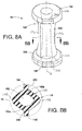
- the pinch valve 76 includes a pinch valve body 190 with a central passage 192 therethrough along a longitudinal axis X.
- the pinch valve 76 further includes first and second end flanges 194 that may be the same size and shape. By having the end flanges 194 be the same, it does not matter whether the pinch valve 76 is installed in a first longitudinal orientation into the pinch valve housing 72, or is flipped around and installed in the inverse longitudinal orientation.
- the pinch valve 76 may further have a pair of diametrically opposed and longitudinally extending ribs 196 along opposite sides of the valve body 190. These ribs 196 provide a localized stiffness to the pinch valve body 190 so that when the pinch valve is exposed to external positive pressure, the portions 198 of the pinch valve body between the ribs 196 act as hinge points to allow the pinch valve to close without high stresses on the valve body 190.
- the pinch valve 76 is closed off by having the major sides 192a of the cats-eye passage 192 being compressed together under force of pneumatic pressure, with the ribs 196 reducing stress on the valve body.
- the elastic ribs 196 are in tension so that when the pressure is released or vented, the ribs 196 assist in returning the pinch valve 76 to an open position.
- the pinch valve body 192 shape includes generally elliptical portions when viewed in transverse cross-section. This shape allows the pinch valve to open and close by the outer ends of the ellipses to act as hinge points when the pinch valve is closed.
- the end flanges 194 may each include a peripheral shape or profile when viewed in plan ( Fig. 9 ) that assists in assembly of the pinch valve 76 into the pinch valve pressure chamber 74 in the pinch valve housing 72.
- the ribs 196 preferably fit inside corresponding longitudinal slots 200 provided in the pinch valve pressure chamber 74 (note that in Fig. 8B the slots 200 and the pressure chamber 74 are illustrated in schematic fashion).
- the end flanges 194 each then has a non-circular peripheral shape.
- Fig. 9 shows all four pinch valve 76 installed in the pinch valve housing 72.
- the flats 202 form a visual appearance as an arrow head or pointer to an assembler (as represented by the arrows 204 in Fig. 9 ) that points to the center of the pinch valve body 72, for example the center column 100. This helps the assembler locate the ribs 196 into the corresponding slots 200 in the pinch valve pressure chamber 74.
- the flats 202 therefore act as alignment indicia in assisting the assembler to install the pinch valve in a proper orientation.
- the flats 202 may be provided optionally in only the upper surface portions of the associated end flanges 194 so that the end flanges 194 have radially symmetric seal surfaces 206 (also see Fig. 10 ) within the pinch valve housing 72.
- the dashed lines R in Fig. 9 show the alignment of the ribs 196 and the slots 200 which are not otherwise visible in the drawing.
- each pinch valve 76 is disposed in a pinch valve pressure chamber or bore 74 (corresponding to 43 in Fig. 1A ) in the pinch valve housing 72.
- the pinch valve pressure chamber 74 generally conforms to the elliptical shape of the pinch valve body 190.
- the pinch valve end flanges 194 are sealingly compressed when the pinch valve housing 72 is assembled between the first powder flow block 64 and the second powder flow block 82.
- the pinch valve pressure chamber 74 receives pressure via a pneumatic pressure passage 208, depending on whether the pinch valve 76 is to be in an open or closed position.
- the pinch valve pressure chamber 74 shares the same longitudinal axis X as the pinch valve 76 disposed therein.
- the pressure passages that open to the pinch valve pressure chamber are formed at ninety degrees from the longitudinal axis of the pinch valve pressure chamber.
- the air pressure from the manifold enters the pinch valve housing from the top end and then a pressure passage is first drilled down into the pinch valve body and then cross-drilled for access to the pinch valve pressure chamber.
- the pressure passage 208 may be formed at an oblique angle relative to the longitudinal axis of the pinch valve pressure chamber 74.
- the pressure passage 208 has an oblique entry angle ⁇ to the pinch valve pressure chamber 74.
- the obliquely angled pressure passage 208 may extend, for example, from an inlet port 209 to the pinch valve pressure chamber 74.
- the oblique angle ⁇ may in some cases be easier to form in the pinch valve housing 72, and also may provide a more effective entry for the air pressure in to the pressure chamber 74.
- a respective barrier element 96 for example a barrier filter in the form of a flat disc 96, is disposed in a port 209 that is provided in the upper side 220 of the pinch valve housing 72.
- the port 209 is in fluid communication with the pneumatic flow passage 208.
- Pneumatic pressure is provided through an associated pneumatic branch 210 in the first powder flow block 64.
- the first powder flow block 64 in addition to providing the powder flow branches between the pinch valves 76 and the gas permeable filters 70, also provides the pneumatic branches for positive pressure from the manifold 14 to the pinch valve pressure chambers 74 in the pinch valve housing 72.
- the barrier elements 96 in this disclosure may be disposed in the pinch valve housing 72 so that they are accessible and easily replaceable when the single releasable fastener 98 is loosened.
- a suitable seal 212 such as an o-ring for example, may be used to provide a pressure tight seal between the pneumatic branch 210 of the first powder flow block 64 and the pneumatic pressure passage 208 in the pinch valve housing 72.
- the pinch valves 76 and the barrier filter discs 96, as well as the seals 212 are therefore examples of replaceable components 214 ( Fig. 3 ) that are readily accessible when the pinch valve housing 72 is separated from the first powder flow block 64.
- the replaceable components 214 typically will be wear items that over time and repeated operation of the dense phase pump 12 need to be replaced either as a repair action or during routine maintenance.
- the pinch valve 250 includes a generally cylindrical body 252 with a central passage 254 therethrough.
- the central passage 254 may have but need not have a non-circular cross-section shape, for example the shape may be like a cats-eye shape, and the pinch valve body may have an elliptical shape in lateral cross-section.
- the pinch valve 250 may also include diametrically opposed ribs 256 and drawing lines 256a on the end flange surfaces (278) are shown to indicate the rib 256 diametric and directional orientation.
- a first difference between the pinch valve 250 and the pinch valve 76 is that the upper end flange 258 and the lower end flange 260 are radially offset from one another. As will be additionally explained below, this radial offset is provided to accommodate the location of the slots in the pinch valve pressure chamber that receive the ribs 256.
- the drawings show a first alignment axis 262 for the upper end flange 258 and a second alignment axis 264 for the lower end flange 260 (best understood from Fig. 8D ).
- the pinch valve 250 may still be reversible in the sense that it may be installed in the orientation of Fig. 8C or flipped around with the lower end flange 260.
- the alignment axes 262, 264 are referenced to an outermost radial extent of the respective end flanges 258, 260.
- the end flanges 194 of Figs. 8A and 8B are non-circular, in contrast to the pinch valves of the 878 patent for example.
- the end flanges 258, 260 are also non-circular but have a more defined pointing profile as best viewed in Fig. 8D .
- the end flanges 258, 260 are radially offset from each other, they may otherwise be the same or matching shape so that the pinch valve 250 can be installed in a first longitudinal orientation or flipped around and installed in an inverse longitudinal orientation.
- each end flange 258, 260 may still be circular, but two straight portions 270, 272 blend to a more defined point or pointer apex 274 that delimits a radially outermost radial extent of each end flange 258, 260.
- each end flange 258, 260 presents a more visually perceptible directional or orientation indication for aligning the pinch valves 250 during assembly into the pinch valve housing so that the pinch valves 250 "point" towards the center of the pinch valve housing 72, for example, radially towards the column 100.
- alignment indicia for example optional directional arrows 276, may be provided on the outer surfaces 278 of the end flanges 258, 260.
- the directional arrows 276 may be molded into the pinch valve body 252 or otherwise provided as needed. Note that the directional arrows 276 directionally align with the pointer apex 274.
- the alignment axes 262, 264 indicate a radial offset included angle ⁇ between the end flanges 258, 260 when viewed in plan. Moreover, the alignment axes 262, 264 also indicate a radial offset included angle ⁇ between each pointer apex 274 and the rib alignment directional axis 256a. In other words, the alignment profile of the end flanges 258, 260 are not only radially offset from each other but also from the ribs 256.
- the ribs when used as part of the pinch valve 250 (or 76 in the embodiment of Figs. 8A and 8B ), are to be aligned with and received in the slots in the pinch valve pressure chamber.
- the slots 200 are formed at right angles with respect to the slots 200 in each adjacent pinch valve pressure chamber 74 on either side thereof, as indicated by the lines R (the lines R indicate the rib orientation).
- the slots 200 and the ribs 196 are oriented in a manner similar to what was done in the 878 patent (which discloses a square pinch valve housing), but this results in the ribs 196 partially obstructing the pressure passage 208 in the location or area where the pressure passage 208 opens to the pressure chamber 74, for example when the pinch valve housing 72 is now of a generally compact cylindrical shape.
- a pinch valve housing 290 is provided with slots 292 that receive the pinch valve ribs 256.
- the slots 292 are radially offset by an angle relative to the location or area where the pressure passage 208 opens to the pressure chamber 74 so that the ribs 256 do not interfere with pressurizing the pressure chamber 74.
- the slots 292 may be rotated by approximately 37° away from the where the pressure passage 208 opens to the pressure chamber 74. This moves the ribs 256 out of the way of where the pressure passage 208 opens to the pinch valve pressure chamber 74.
- the pressure passage 208 faces a flatter portion of the pinch valve body that is between the rib 196 and the hinge 198, as this helps compress the pinch valve closed.
- This is best understood from Fig. 9B .
- the angle of radial offset between the ribs 256 and the opening of the pressure passage 208 to the pressure chamber 75 will depend on the shape, design, dimensions and so forth of the pinch valve housing 72 as well as the design of the pinch valve 250, particularly the shape of the elliptical portions. Therefore, 37° is but one example of a radial offset that assures that the pressure passage 208 does not open to the pressure chamber 74 in an orientation that would be obstructed by the ribs 256.
- this radial offset between the ribs 256 and the opening of the of the pressure passage 208 to the pressure chamber 74 assures that the pressure chamber 208 does not open to the pressure chamber 74 facing the hinge location 198 ( Fig. 9B ) because if that were the case then, when the pinch valve is in a closed position, the pinch valve hinge area 198 could obstruct the pressure passage 208 and the pressure passage 208 might not be vented to re-open the pinch valve.
- pressure passage 208 may be formed at an oblique entry angle ⁇ to the pinch valve pressure chamber 74 as described hereinabove.
- this angle is determined by the radial offset angle between the ribs 256 and the opening of the pressure passage 208 to the pressure chamber 74.
- the orientation of the pressure chamber 74 (as measured from the plane which bisects the pinch valve ribs) rotates about the longitudinal center axis of the pinch valve housing 72.
- an angle from the horizontal plane when viewed from the top as shown in Figs.
- the selection of the angle ⁇ determines the angle ⁇ if it is desired to have the pinch valve 250 installable in either longitudinal orientation. And the selection of the angle ⁇ may be made based on the specific needs to pressurizing the pinch valve pressure chamber 74, such as the location where the pressure passage 208 opens to the pressure chamber 74 and the shape and design of the pinch valve 250. Therefore, the exemplary values for ⁇ and ⁇ as well as the radial offset angle between the ribs 256 and the pressure passage 208 opening to the pressure chamber 74, may be chosen based on the specific geometries of a particular pinch valve housing.
- the pinch valve housing 72 can be separated from the first powder flow block 64 for access to the replaceable components 214 such as the pinch valves 76 and the barrier filter discs 96 and the o-rings 212. These replaceable components can be replaced without any further disassembly of the dense phase pump 12, although optionally the pinch valve housing 72 can be also separated from the second powder flow block 82 when the single releasable fastener 98 is removed. This may be done, for example, if the entire pinch valve housing 72 is to be swapped or replaced with a different pinch valve housing 72.
- the pinch valve housing 72 can be readily accessed for servicing to replace the replaceable components 214 and/or the pinch valve housing 72 itself without having to remove any hoses that are connected to the dense phase pump 12 during normal operation.
- the pinch valve housing 72 may be serviced without removing the supply hose 92 or the gun hose 94 from the second powder flow block 82 ( Fig. 1 ); or for embodiments in which the 878 type of purge connections are used, without removing the purge air hoses from the check valves.
- An exemplary method for replacing one or more replaceable components includes the step of loosening the single releasable fastener 98 so as to release the axial compression between the first powder flow block 64, the pinch valve housing 72 and the second powder flow block 82.
- the first housing 60 ( Fig. 1 ) can remain attached to the manifold 14 if so desired.
- the first powder flow block 64 may be attached to the pump body 62 using the fasteners 80 such as a plurality of bolts.
- the pinch valve housing 72 may be serviced without separating the first powder flow block 64 from the pump body 62 or the pump body 62 from the manifold 14.
- the pinch valve housing 72 may be axially pulled away or separated from the first powder flow block 64 (note that although the exemplary embodiments illustrate the dense phase pump 12 in a vertical orientation as is done in common practice, such is not required for operation of the pump).
- the replaceable components 214 such as one or more of the pinch valves 76, the barrier elements 96 and the seals 212, may be replaced with different or new ones.
- the pinch valve assembly housing 72 may be further separated from the second powder flow block 82 and wholly replaced, or in some cases it may be easier to service the replaceable components 214 with the pinch valve housing also separated from the second powder flow block 82 as a standalone assembly.
- the dense phase pump 12 can be reassembled by mating up the pinch valve housing 72 with the first powder flow block 64 and the second powder flow block 82 with the pinch valve housing 72 and then tightening the single releasable fastener 98.
- alignment structures may be provided. Proper radial alignment, for example, of the pinch valve housing 72 relative to the first and second powder flow blocks 64, 82, assures that the various pneumatic and powder flow passages which extend between these bodies are correctly aligned and sealed.
- a first alignment concept contemplates keyed elements 215 ( Fig. 4 ) on the attachable bodies so as to assure proper radial alignment.
- the pinch valve housing 72 may be provided with one or more extensions or tabs 216 that are circumferentially disposed about the outer periphery of the pinch valve housing 72.
- tabs 216 mate with conforming slots 218 that are circumferentially disposed about the outer peripheries of the first and second powder flow blocks 64, 82.
- Each tab 216a on the pump facing side 220 of the pinch valve housing 72 is received in a conforming slot 218a on the pinch valve facing side 222 of the first powder flow block 64.
- each tab 216b on the opposite facing side 224 of the pinch valve housing 72 is received in a conforming slot 218b on the pinch valve facing side 226 of the second powder flow block 82.
- the mating tabs 216 and conforming slots 218 may be disposed slightly radially inward along the outer wall 228 of the pinch valve housing 72 so that the keyed elements 215 are enclosed when the pinch valve housing 72 is assembled with the first and second powder flow blocks 64, 82.
- the keyed elements 215 may be located elsewhere other than along the outer peripheries if so needed, and may have any suitable shape or geometry.
- the tabs 216 and the conforming slots 218 may be keyed to each other by having at least one of the tabs 216 and its conforming slot 218 on each side 220, 224 of the pinch valve housing 72 be of a different size or shape than the others.
- the pinch valve housing 72 can be assembled to the first and second powder flow blocks 64, 82 in only one radial orientation and the keyed elements 215 may also be selected so that the pinch valve housing 72 can be assembled in only one axial orientation (for example, only with the first side 220 assembled with the first powder flow block 64 and not upside down).
- the keyed elements 215 need only be designed to provide radial alignment.
- the keyed elements 215 also cooperate to restrict relative rotation between the pinch valve housing 72 and the first and second powder flow blocks 64, 82.
- This may be realized, for example, by providing a close dimensional fit between the tabs 216 and the conforming slots 218 so that the assembled keyed elements 215 restrict relative rotation between the pinch valve housing 72 and the first and second powder flow blocks 64, 82.
- the close dimensional fit between the tabs and slots amounts to an interference fit is a matter of design choice.
- the close dimensional fit is sufficient to prevent relative rotation between the assembled bodies but not so tight so as to make assembly or disassembly less useful. From these teachings, many other ways to provide a keyed connection and alignment between the assembled bodies 72, 64 and 82 will be readily apparent to those skilled in the art.
- the keyed elements 215 may be disposed as needed on the several mating bodies.
- the tabs 216 may be provided on the first and second powder flow blocks 64, 82 and the slots 218 disposed on the pinch valve housing 72.
- all three bodies 72, 64 and 82 may have tabs and slots that cooperate with conforming tabs and slots on the facing sides of the attached bodies.
- the keyed elements 215 restrict the pinch valve housing 72 to being assembled in preferably a single radial position relative to the first and second powder flow blocks 64, 82.
- the differently shaped or sized keyed elements 215 may be visually distinct to an assembler, such may not always be the case.
- exterior alignment indicia 230 may be provided.
- Each of the pinch valve housing 72, the first powder flow block 64 and the second powder flow block 82 may include an exterior alignment indicia 230 that aligns with the adjacent body to indicate correct radial alignment.
- the exterior alignment indicia may be in the form of one or more directional pointers 232 on the outer surface 234 of the pinch valve housing 72 that align with directional pointers 236 on the respective outer surfaces 238, 240 of the first powder flow block 64 and the second powder flow block 82 when the bodies are radially aligned.
- the exterior alignment indicia 230 may have any suitable form and appearance.
- the exterior alignment indicia 230 may be embossed raised surfaces or reliefs on the outer surfaces 234, 238 and 240, or may be applied on labels or printed on, or any other suitable technique may be used as needed.
- the exterior alignment indicia 230 may be used to assist in the assembly of the dense phase pump 12, and after the pump is assembled and the single releasable fastener 98 tightened, the exterior alignment indicia 230 provide visual confirmation that the pinch valve housing 72 is properly and radially aligned with the first and second powder flow blocks 64, 82.
Abstract
Description
- The inventions relate generally to material application systems that are used for spraying powder coating material onto a work piece or object. More particularly, the inventions relate to material application pumps, for example, dense phase pumps.
- A material application device is used to apply powder coating material to an object, part or other work piece or surface. A material application device is also referred to herein as a spray gun. The powder coating material can be delivered from a powder pump to a spray gun in dilute phase or dense phase. Dilute phase delivery refers to a powder flow or stream that is a lean mixture, or in other words has a higher ratio of flow air to powder. Dilute phase powder pumps are most commonly used in the form of a Venturi style pump that uses a larger volume of air to draw powder from a supply and push the powder to the spray gun. Dense phase delivery refers to a powder stream that is a rich mixture, or in other words has a lower ratio of flow air to powder. Dense phase pumps are commonly used in the form of a pump chamber that uses pressure to fill and empty a pump chamber but with a lower flow air volume, referred to hereinafter as flow air. Because dense phase delivery systems use less flow air, the powder hoses can be made smaller in diameter compared with powder hoses used with dilute phase delivery systems.
- An example of a dense phase pump is described in United States Patent No.
7,997,878 (the "878 patent" hereinafter). - In an embodiment presented in this disclosure, a dense phase pump includes a first housing and a second housing that is attached to the first housing by a single releasable fastener. In a more particular embodiment, the second housing receives one or more replaceable components. In another embodiment the replaceable components may include a pinch valve or a barrier element such as, for example, a barrier filter, or both.
- A method for removing or replacing a replaceable component, for example a pinch valve or barrier element, that is disposed in a dense phase pump is also provided, and in an exemplary embodiment the method includes releasing a single releasable fastener to provide access to the replaceable component.
- In another embodiment presented herein, a pinch valve has an annular body with first and second end flanges. One or both of the end flanges has a non-circular profile for aligning the pinch valve when the pinch valve is installed in a pinch valve housing or valve body.
- In another embodiment presented in this disclosure, a dense phase pump includes a pump housing having at least one gas permeable member that can be purged from one end of the gas permeable member along a longitudinal axis of the gas permeable member, and the pump housing has a purge inlet such that purge air enters the pump housing along an axis that is transverse the gas permeable member longitudinal axis.
- In another embodiment, a pinch valve housing includes non-circular pinch valve with two end flanges that are radially offset from each other.
- In another embodiment, a pinch valve includes alignment indicia for indicating correct orientation of the pinch valve when the pinch valve is assembled into a pinch valve housing.
- In another embodiment, a dense phase pump having two or more housings that are assembled together has alignment indicia on exterior surfaces of the housings.
- The invention will now be further described by way of example with reference to the accompanying drawings, in which:
-
Fig. 1 is an isometric view of a dense phase pump and manifold assembly that may be used with the present inventions, -
Fig. 1A is a functional block diagram of the dense phase pump embodiment ofFig. 1 , -
Fig. 2 is a front end elevation of the assembly ofFig. 1 , -
Fig. 3 is an exploded perspective of the assembly ofFig. 1 , -
Fig. 4 is a side elevation of the assembly ofFig. 1 , in longitudinal cross-section along the line 4-4 inFig. 2 , -
Fig. 4A is an enlarged view of a portion ofFig. 4 , -
Fig. 5 is a side elevation of the assembly ofFig. 1 , in longitudinal cross-section along the line 5-5 inFig. 2 , -
Fig. 6 is an enlarged side elevation of an interface between the pump body and the manifold ofFig. 1 , in longitudinal cross-section, -
Fig. 7 is an enlarged view of a check valve assembly inFig. 6 , in longitudinal cross-section, -
Figs. 8A and 8B are isometric and lateral cross-sectional views of a pinch valve, -
Figs. 8C and 8D illustrate another embodiment of a pinch valve, in isometric and plan views, -
Fig. 9 is a top plan view of a pinch valve housing and replaceable components installed therein, -
Figs. 9A and9B illustrate in plan and lateral cross-section another embodiment of a pinch valve housing and pinch valves installed therein, (Fig. 9B being taken along theline 9B-9B inFig. 2 ), -
Fig. 10 is cross-sectional illustration of a set of replaceable components in an installed condition in a pinch valve housing, -
Figs. 11 and11A are isometric views of the powder flow blocks and pinch valve housing in a partially rotated view to show an alignment feature. - Although the features are described in terms of exemplary embodiments of a dense phase pump such as embodiments that are described in the 878 patent, this is but one example of a dense phase pump that may utilize one or more of the features. The disclosure is not limited to a strict definition of "dense phase", but rather we refer to a dense phase pump as being one in which powder coating material is pulled into a pump chamber by negative pressure and pushed out of the pump chamber by positive pressure, by utilization of a gas permeable filter. Also, while the dense phase pump described in the 878 patent has found excellent commercial success, we have developed modifications and features that improve the serviceability of wear parts, and also that simplify assembly and of the pump. However, it is important to note that the features and improvements herein may be used with additional or alternative dense phase pump designs other than what is described herein or in the 878 patent.
- Directional references herein to axial and radial are relative directionally to a central longitudinal axis X of the indicated element, for example the dense phase pump (
Fig. 2 ), unless otherwise noted by context or description. A reference numeral in parentheses indicates that the related element is further described in an additional detailed embodiment hereinbelow. - A first inventive concept provides a dense phase pump that is modular in design in that the pump is an assembly of two or more housings that can be conveniently assembled and separated so as to provide access to one or more replaceable components or parts. By replaceable components we mean parts that tend to wear out over time but such wear does not render the overall pump useless. By simply replacing these parts the pump can continue to be used in service.
- In an embodiment of the first concept, a dense phase pump has two housings that are attached together using a single releasable fastener. In this way, the single fastener can be released so as to allow the two housings to be separated thereby providing access to the replaceable components. In a further exemplary embodiment, the replaceable components may include one or more pinch valves or one or more barrier elements or both. Additional embodiments of this first concept are presented herein. An embodiment of a method for replacing replaceable component in a dense phase pump is also presented herein.
- A second inventive concept provides in an embodiment a pinch valve that has a shape or profile for aligning the pinch valve when the pinch valve is installed in a pinch valve body. In another embodiment of the second concept, a pinch valve has two end flanges, with each end flange having a shaped periphery for aligning the pinch valve when the pinch valve is installed in a pinch valve body. In another embodiment, the two end flanges may have the same size and shape so that the pinch valve can be installed in either of two longitudinal orientations that are inverse with respect to each other. In another embodiment, the end flanges may be radially offset from one another relative to the longitudinal axis of the pinch valve body. In another embodiment, the two end flanges may have a non-circular shape. In another embodiment, the two end flanges may have alignment indicia thereon. Additional embodiments of this second concept are presented herein.
- A third inventive concept provides in an embodiment a dense phase pump having a pump chamber that can be purged by a purge gas flow that enters the pump off-axis from a purge path through the pump chamber. In another embodiment, a dense phase pump includes a pump housing having at least one gas permeable member that can be purged from one end of the gas permeable member along a longitudinal axis of the gas permeable member, and the pump housing has a purge inlet such that purge air enters the pump housing along an axis that is transverse the gas permeable member longitudinal axis. Additional embodiments of this third concept are presented herein.
- With reference then to
Fig. 1 , a dense phase pump andmanifold assembly 10 includes adense phase pump 12 and a manifold 14. Thedense phase pump 12 may be designed and operated generally in accordance with the 878 patent except as otherwise noted herein, for example, but alternatively many other dense phase pump designs may be used as needed. For purposes of the present disclosure, it is sufficient to understand that the dense phase pump pulls powder coating material from acoating material supply 16 and pushes the powder coating material to aspray gun 18. Thesupply 16 may be any suitable apparatus and design known in the art or later developed. A common example is a hopper that may have a fluidized bed, or alternatively, powder coating material can be supplied from a box or container or other suitable supply. Thespray gun 18 may also be any suitable apparatus and design such that the spray gun receives a dense phase powder flow and produces a spray pattern that is suitable for a coating operation. An example of a suitable dense phase spray gun is the PRODIGY® model spray gun available from Nordson Corporation, Westlake, Ohio. Alternatively, many other dense phase spray guns known in the art or later developed may be used. -
Fig. 1A illustrates in simplified schematic form the basic parts of adense phase pump 12, for example the pump disclosed in the 878 patent. Afirst control valve 20 is used to control the flow of powder coating material from thecoating material supply 16 into an inlet 22 of thepump 12. Asecond control valve 24 is used to control the flow of powder coating material from an outlet 26 of thepump 12 to thespray gun 18. Thepump 12 may be further realized using apump chamber 28. Thepump chamber 28 includes a gaspermeable filter 30 that is disposed in afilter pressure chamber 32 with anannulus 34 that surrounds the gaspermeable filter 30. Powder coating material is pulled into thepump chamber 28 by opening thefirst control valve 20 and applying negative pressure 36 (P-) to theannulus 34. Powder coating material is pushed out of the pump chamber by closing thefirst control valve 20, removing the negative pressure P-, opening thesecond control valve 24 and applying positive pressure 38 (P+) to theannulus 34. The first andsecond control valves control valves - For a
pump 12 such as described in the 878 patent, powder coating material flows into and out of oneend 30a of the gaspermeable filter 30. Therefore, a first powder flow Y-block 40 is used to provide inlet and outletpowder flow branches control valves - The
pinch valves valve pressure chamber 43 associated with a pinch valve, the external pressure acting on the pinch valve body compresses or pinches the valve closed. In an exemplary embodiment, when the pressure is released (the pressure chamber may be vented to atmosphere to release the pressure) the pinch valve opens due to the natural elastic properties of the pinch valve body. Alternatively, negative pressure optionally may be applied to thepressure chamber 43 to further assist the pinch valve to return to the open position. - When the
control valves valve pressure chamber 43 in the pinch valve body (54). This allows the use ofpositive pressure 45 and optionallynegative pressure 47 to be applied to the pinchvalve pressure chamber 43 to close and open the pinch valve. Note that optionally eachpinch valve valve pressure chamber 43 to operate each pinch valve. In order to apply pressure to the pinch valve pressure chambers, a first barrier element orbarrier filter 42 may be used in the pressure passage. A barrier element functions to prevent powder coating material from being drawn or blow back into a pressure source in the manifold 14 or into the ambient environment. An example of a barrier element is a porous filter that allows air to pass through but blocks a powder coating material. The barrier filters 42 used in commercial practice are disposed in the first Y-block 40. Each pinch valve may have an associatedbarrier element 42 for embodiments wherein each pinch valve is individually controlled. The manifold 14 provides the timing and supply for pressure applied to the pinchvalve pressure chambers 43. - Also, in order to provide a continuous powder flow output from the
pump 12, thepump 12 may optionally include twopump chambers 28, 28' (we use a prime ' to indicate like parts for a two chamber pump) each having its own pair ofcontrol valves 20/20', 24/24'. Thus, a typical dense phase pump may have two gas permeable filters 30, 30' and fourcontrol valves 20/20', 24/24' and fourbarrier filters 42, 42'. The first Y-block 40 may be provided with fourpowder flow branches 44/44' and 46/46'. The use of the second pump chamber 28' also results in use of a second Y-block 48 because as thefirst pump chamber 28 is pulling powder from thesupply 16, the second pump chamber 28' is pushing powder out to thespray gun 18 and vice-versa. Therefore, the second Y-block 48 is disposed to providepowder flow branches supply 16, thespray gun 18 and thecontrol valves 20/20', 24/24'. In the 878 patent, thecontrol valves 20/20', 24/24' are positioned in avalve body 54, which may be transparent to allow observation of the operation of the control valves, as well as to detect a ruptured pinch valve. When a pinch valve ruptures, powder escapes into thepinch valve housing 72 and this will indicate to an operator to change out the pinch valve or thepinch valve housing 72 with new pinch valves. - Powder coating systems frequently use many different types and color of powder coating material, and when the type or color of the powder coating material is changed, the
pump 12 must be cleaned. Part of the cleaning operation is to purge thepump chambers 28, 28' as well as other portions of the powder flow paths. One of the purging options described in the 878 patent is to apply apurge gas 56 into an open or purgeend 30b/30b' of the gaspermeable filters 30, 30' that is opposite the single inlet/outlet end 30a/30a' of the gaspermeable filters 30, 30'. Control of the purge timing and pressure source is carried out in themanifold 14. - The
filter pressure chambers 32, 32' along with the gaspermeable filters 30, 30' are disposed in apump housing 58. In the embodiments shown in the 878 patent, thepump housing 58 interfaces with the manifold 14 in order to provide the various pressure signals needed to operate thecontrol valves 20/20', 24/24' and thepump chambers 28, 28'. The purge lines 56 separately attach to thepump housing 58 from the top of the pump housing and in-line with the check valve flow path. - Further explanation of the design and operation of the
dense phase pump 12 is provided in the 878 patent, but the foregoing description is sufficient to understand and practice the present inventions. - Turning next to
Figs. 2 and3 , an embodiment of the densephase delivery pump 12 in accordance with the present disclosure includes afirst housing 60, which may include a pump body orhousing 62 and a first or upper powder flow block orhousing 64. Thefirst housing 60 has afirst pump chamber 66 and asecond pump chamber 68 which each have respective gaspermeable filters 70 associated therewith (see alsoFig. 5 ). For the most part, the gaspermeable filters 70 are disposed in thepump body 62 although a lower portion of each may extend into the firstpowder flow block 64. Alternatively the gaspermeable filters 70 may be fully disposed in thepump body 62. - With reference also to
Figs. 4 and5 , apinch valve housing 72 preferably but not necessarily is a transparent unitary body that includes four pinch valve pressure chambers 74 (only two are shown inFig. 4 ) that each receives acontrol valve 76. Note inFig. 3 that thecontrol valves 76 are shown partially installed in their respective pinchvalve pressure chambers 74. Eachcontrol valve 76 may be realized in the form of an elastic flexible pinch valve made of a suitable material, for example, natural rubber. - The
pump body 62 receives first and secondcheck valve assemblies 78 which will be further described hereinbelow. The firstpowder flow block 64 may be attached to the bottom side of thepump body 62 withbolts 80, and includes powder flow branches that serve as inlet and outlet powder flow passages for thepowder chambers 70a. Agasket 81 may also optionally be used to seal air passages between thepump body 62 and thefirst powder block 64. - Reference herein to top, bottom, upper and lower are for convenience when viewing the drawings, but do not require that the
dense phase pump 12 be oriented in any particular alignment during use; although a vertical or upright orientation as depicted in the drawings is common. - As in the 878 patent, because the exemplary embodiment uses two
pump chambers housing 82. Thesecond flow block 82 providespowder flow branches 84, 86 (there are a total of four powder flow branches in the secondpowder flow block 82, two for eachpump chamber pump inlet connection 88 and apump outlet connection 90. Thepump inlet connection 88 is connectable to apowder supply 16 through asupply hose 92 and thepump outlet connection 90 is connectable to aspray gun 18 by agun hose 94. - With reference to
Figs. 2 and4 , we illustrate another embodiment of the first concept discussed above. First, it should be noted that thepinch valves 76 may be thought of as a wear item, meaning that due to the repetitive flexing of the pinch valve, thepinch valves 76 tend over time to weaken or wear out or rupture and need replacing. Also, we have moved the barrier filters 96 to be disposed in thepinch valve housing 72 rather than in the upper Y-block (40) as done in prior designs. The barrier filters 96 are also wear items because the barrier filters 96 tend over time to become blocked or blinded with powder or at least to have reduced porosity. By disposing the barrier filters 96 in thepinch valve housing 72 with thepinch valves 76, easier access is provided for replacing the barrier filters 96. Thepinch valves 76 and the barrier filters 96 are referred to herein as example of replaceable components (214,Fig. 3 ) because they tend to wear out over time and can be serviced so that the overall pump can continue in use. Other pump designs may use additional or different replaceable components. - In order to simplify service access to the replaceable components (214) in the
pinch valve housing 72, which reduces repair, maintenance and down time of thedense phase pump 12, a singlereleasable fastener 98 is used to attach the secondpowder flow block 82 and thepinch valve housing 72 to thepump housing 60. In an embodiment, for example,Fig. 3 herein, the secondpowder flow block 82 and thepinch valve housing 72 may be attached to the firstpowder flow block 64 using the singlereleasable fastener 98. In this manner, by simply loosening or releasing the singlereleasable fastener 98, thepinch valve housing 72 can be removed from thepump housing 60 for access to thereplaceable components 76, 96 (214). The replaceable components (214) can be replaced individually as needed. Alternatively, the entirepinch valve housing 72 with replacement components as a discrete assembly can be installed in place of the previously installedpinch valve housing 72. Reassembly is also simplified by using the singlereleasable fastener 98. - In one embodiment, the single
releasable fastener 98 may be realized in the form of an end threaded bolt, however, many other types of releasable fasteners may alternatively be used. We use the term releasable to indicate that thesingle fastener 98 is used for assembly and disassembly of thepinch valve housing 72 as can occur for normal routine maintenance and repair. For access to the replaceable components (214), and/or for removal and replacement of the discrete assembly of thepinch valve housing 72 and the replaceable components (214), we refer herein to releasing or loosening the singlereleasable fastener 98 because complete removal of the fastener may not be necessary for all repair or maintenance activities. But if needed, the singlereleasable fastener 98 can be completely withdrawn. It is important to note that the single releasable fastener concept may be used in dense phase pumps other than the exemplary embodiment herein, for example, with the dense phase pump described in the 878 patent or others known or later developed. - With reference to
Figs. 3 ,4 and4A , the singlereleasable fastener 98 extends through acentral bore 100d of amulti-section column 100. Preferably but not necessarily thecolumn 100 is centrally located with respect to thepinch valve 76 locations, for example, along a central longitudinal axis X of thedense phase pump 12. Thepinch valves 76, for example, may be uniformly spaced about the central longitudinal axis of thepinch valve housing 72. For an exemplary embodiment of thepinch valve housing 72, thepinch valves 76 may be disposed approximately ninety degrees apart from each other. The central location of thecolumn 100 then facilitates an even distribution of compressive forces as thefastener 98 is tightened. Afirst column section 100a is centrally positioned in the secondpowder flow block 82; asecond column section 100b extends centrally through thepinch valve housing 72, and athird column section 100c is centrally positioned in the first powder flow block 64 (see alsoFigs. 11 and11A ). Thecolumn 100 therefore may be realized withsections 100a-100c with each column section comprising a single central opening in the associated body that the singlereleasable fastener 98 extends through or into. For example, thepinch valve housing 72 includes thecentral column section 100b that extends all the way through thepinch valve housing 72 and provides a single central opening for the single releasable fastener. - The
column 100 may be integrally formed as part of the second powder flow block 82 (column section 100a), the pinch valve housing 72 (column section 100b), and the first powder flow block 64 (column section 100c). The threesections 100a-100c all align axially with each other so that the singlereleasable fastener 98 extends through thecentral bore 100d and into all threesections 100a-100c and may have a threadedend 98a that can be screwed into a threadedinsert 102 in the firstpowder flow block 64. As thefastener 98 is tightened into the threadedinsert 102, thefastener 98 is under tension and pulls together an upper side (226) of the secondpowder flow block 82 against a bottom or facing side (224) of thepinch valve housing 72, and an upper side (220) of thepinch valve housing 72 against the bottom or facing side (222) of the firstpowder flow block 64 and holds these threepieces Fig. 3 ). The threadedinsert 102 may comprise metal such as brass for example, and may contact ametal spring 103 in order to provide electrical ground for thefastener 98. - The
pinch valves 76 each include two end flanges (194) that will be further described below. These end flanges are axially compressed when the singlereleasable fastener 98 is tightened to form tight seals so that powder coating material flowing through thepinch valves 76 does not by-pass around the pinch valves and escape into or out of thepinch valve body 72. It is useful then that the singlereleasable fastener 98 be sufficiently robust and tightened so that thepinch valves 76 are adequately compressed to seal. The singlereleasable fastener 98 may include asocket 98b that accepts an Allen wrench to allow sufficient torque to be applied to thefastener 98. - It is also useful that the single
releasable fastener 98 not be over-tightened with too much torque as this could crush and damage thepinch valve 76 end flanges (194). Themulti-section column 100 functions as a stop mechanism to prevent over-torque being applied to the singlereleasable fastener 98. Thefirst column section 100a has an upperdistal end 104 that contacts a lowerdistal end 106 of thesecond column section 100b; and thesecond column section 100b has an upperdistal end 108 that contacts a lowerdistal end 110 of thethird column section 100c. The distal ends 104, 106, 108, 110 make contact so as to form the continuouscentral bore 100d within a continuous supportingcolumn 100. In particular, the distal ends 104, 106, 108 and 110 make full contact at a predetermined or controlled compression of thepinch valves 76. Once all threecolumn sections 100a-c are in full contact, additional axial movement or compression of the threebodies pinch valves 76 cannot be further compressed or over-compressed. Thus, the facing contacting surface pairs, namely the distal ends 104/106 between the upper side (220) of thepinch valve housing 72 and the lower side (222) of the firstpowder flow block 64, and the distal ends 108/110 between the lower side (224) of thepinch valve housing 72 and the upper side (226) of the secondpowder flow block 82, function as positive stops to prevent over-tightening or over-torque of the singlereleasable fastener 98 which could otherwise over compress or damage the pinch valve end flanges (194). - With reference to
Figs. 5 ,6 and7 , as noted above the manifold 14 provides purge air to thedense phase pump 12. One of the purge modes that can be used is to direct a flow of pressurized air longitudinally through each gaspermeable filter 70. We use the term longitudinally in this context to indicate the purge air flow path from anopen purge end 30b to an open inlet/outlet end 30a of the gas permeable filter 70 (seeFig. 1A ). Since both pumpchambers - The
dense phase pump 12 includes the pair ofpump chambers 66, 68 (only thepump chamber 68 is visible inFigs. 5-7 ). Thepump chamber 68 includes abore 112 that extends through thepump body 62. Disposed within thebore 112 is thecheck valve assembly 78 and a gaspermeable filter 70.Seals 114, such as o-rings for example, provide pressure tight seals at either end of the gaspermeable filter 70 so that a portion of thebore 112 serves as the pressure chamber 32 (Fig. 1A ) volume with a portion of thebore 112 wall providing apressure chamber wall 116 about the gaspermeable filter 70 disposed therein. The gaspermeable filter 70 may be a hollow cylinder comprising a gas porous material such as, for example, porous polyethylene. This same material may also be used for thebarrier filter discs 96. Thecentral volume 70a of the hollow cylinder thus serves as a powder chamber by which powder is drawn into and pushed out of thedense phase pump 12. The gaspermeable filter 70 fits within thepressure chamber wall 116 so as to provide anannulus 118 that serves as a pressure chamber for the gaspermeable filter 70. Theannulus 118 is in fluid communication (not shown inFig. 5 ) with sources of the positive pressure 38 (P+) and negative pressure 36 (P-) (Fig. 1A ) as described above and in the 878 patent so that powder coating material is drawn into thepowder chamber 70a under negative pressure and pushed out of thepowder chamber 70a under positive pressure. The lower end of the gaspermeable filter 70 may be received in acounterbore 120 that may be in the firstpowder flow block 64, and aligned so that thepowder chamber 70a is in fluid communication with an inletpowder flow branch 122 and an outletpowder flow branch 124 which in turn are in fluid communication with associatedpinch valves 76. By having a portion of each gaspermeable filter 70 extend out of thepump body 62, thefilters 70 are easily accessed for installation and removal when the bolts 80 (Fig. 3 ) are not holding thepump body 62 and the firstpowder flow block 64 together. - The
pump body 62 is attached to the manifold 14 by bolts 126 (Figs. 1 and2 ). As noted above, the manifold 14 in part is an air manifold that provides various pressure signals and conditions to thedense phase pump 12, including pressure for thepump chambers Fig. 1A ), and pressure for thepinch valves 76. Therefore, we provide a sealedinterface 128 between thepump body 62 and the manifold 14 for air passages (not shown) to pass therebetween. Aback side 130 of thepump body 62 presents a first planar surface 132 that faces a secondplanar surface 134 that is presented by afront side 136 of the manifold 14. The sealedinterface 128 is compressed between the two facingplanar surfaces 132, 134 when thebolts 126 are tightened down. The sealedinterface 128 may be realized, for example, with agasket 138. - With particular reference to
Fig. 7 , thecheck valve assembly 78 includes acheck valve body 140 that may be threadably installed in a threaded portion of thebore 112 wall.Seals 142 such as o-rings provide a sealedchamber 144 that is provided in thepump body 62 about a portion of thecheck valve body 140. A purge inlet bore 146 is provided in thepump body 62. Acoupler 148 having anair passage 148a therethrough is installed in one end of the purge inlet bore 146 and inserts into a purge outlet bore 150 in themanifold 14. The purge outlet bore 150 receives purge air from apurge air source 152 through an air fitting 154 in themanifold 14. Timing and control of the purge air is provided by valves and controls in themanifold 14. Thecoupler 148 bridges theinterface 128 between thepump body 62 and the manifold 14 to provide a pressure tight sealedair passage 148a for purge air from the manifold 14 into thepump body 62. Aseal 156 such as an o-ring, for example, may be used to seal thecoupler 148 in the manifold purge outlet bore 150. - The purge inlet bore 146 opens to the sealed
chamber 144 and therefore provides apurge air inlet 146a to thecheck valve assembly 78 via the sealedchamber 144. The manifold purge outlet bore 150 provides apurge air outlet 150a from the manifold 14 that is in fluid communication with thepurge air inlet 146a to thecheck valve assembly 78. - A
check valve plug 158 may be threadably attached to thecheck valve body 140 and includes a hollowcylindrical extension 160. Thecylindrical extension 160 is provided with one or more through ports or holes 162 that establish fluid communication between the sealedchamber 144 and aninterior cavity 164 of thecheck valve body 144. Disposed within thecheck valve cavity 164 is a balltype check valve 166. Theinterior cavity 164 of thecheck valve body 144 is in fluid communication with thepowder chamber 70a only when the check valve is open. Thecheck valve 166 includes a sleeve-likevalve seat member 168 that provides avalve seat 168a; avalve member 170, for example a ball; and abiasing element 172, for example, a spring. Thespring 172 is disposed between thevalve member 170 and thevalve seat 168 in a compressed condition so as to urge theball 170 into sealing engagement with thevalve seat 168a. Thecheck valve 166 is therefore in a normally closed condition with theball 170 urged against thevalve seat 168a in the absence of purge air pressure. - When purge air is supplied to the
check valve 166, the check valve remains closed until the purge air pressure exceeds the cracking or opening pressure of thecheck valve 166. The opening pressure of thecheck valve 166 can be controlled by appropriate selection of the strength of the biasingelement 172. When the purge air pressure exceeds the opening pressure of thecheck valve 166, thevalve member 170 moves away from thevalve seat 168a and purge air flows through thecheck valve 166 and into thepowder chamber 70a to purge powder therefrom. - The
valve seat cage 168 may optionally include a secondvalve seat member 174 that presents asecond valve seat 174a on the downstream end of the valve seat cage. This valve seat may be used to cutoff purge flow in the event of an overpressure condition in the purge supply. Thesecond valve seat 174 may be sealed in thecheck valve body 140 by aseal 176 such as an o-ring, for example. - The flow path of purge air when the
check valve 166 is open is represented schematically by the arrow 178 (seeFigs. 6 and7 ). Thepurge air 178 enters thepump body 62 from thecoupler 148 that is in fluid communication with thepurge air supply 152. Thepurge air 178 flows into the sealedchamber 144 and because the chamber is sealed, the purge air is forced up towards and through theholes 162. When the purge air pressure exceeds the opening pressure of thecheck valve 166, theball 170 unseats from thevalve seat 168a and purgeair 178 flows along the flow axis of thecheck valve 166 and passes into and through thepowder chamber 70a. FromFig. 1A it will be noted that with the proper valves open during purge, the purge air can pass all the way through to thespray gun 18 and purge the spray gun at the same time, as well as purge the powder paths all the way back to thepowder supply 16 if so needed. Note that thepurge air 178 enters the gaspermeable filter 70 at the open purge end 180 (corresponding to 30b inFig. 1A ) thereof that is opposite the open end 182 (corresponding to 30a inFig. 1A ) that serves as both the inlet and outlet of thepump chamber 68 for powder flow. - In prior designs such as the 878 patent, purge air enters the gas
permeable filter 70 through the sameopen end 30b of the gaspermeable filter 30 but is supplied through an air hose and connector that are mounted on top of the check valve assembly meaning that, in the 878 patent, the purge air is supplied to the check valve in-line or coaxial with theflow axis 186 of the check valve and thelongitudinal axis 188 of the gaspermeable filter 30. But we have found that when many dense phase pumps are being used in a powder coating system, there is a large number of purge air hoses which makes the system cluttered, less manageable and less aesthetically appealing. - As shown in
Fig. 7 , thepurge air 178 enters thepurge air inlet 146a of thecheck valve assembly 68 off-axis from thelongitudinal axis 188 of powder flow through the gaspermeable filter 70, which is optionally in-line or coaxial with theflow axis 186 of thecheck valve 166. The illustrated embodiment shows that thepurge air 178 enters thepump body 62 along a purge flowdirectional inlet axis 184 that is transverse thedirectional flow axis 186 of thecheck valve 166. The check valvedirectional flow axis 186 may be but need not be in-line with thelongitudinal axis 188 of the gaspermeable filter 70 and thepowder chamber 70a. - The
purge air 178 enters thepump body 62 and flows into thecheck valve assembly 68 along a purgeflow inlet axis 184 that is transverse thelongitudinal axis 188 of the gaspermeable filter 70. Thepurge air 178 then flows along a flow path that forces the purge air to change direction by ninety degrees as it enters thecheck valve 166 so that the purge air flow is in-line with the checkvalve flow axis 186 and thus also in-line with thelongitudinal axis 188 of the gaspermeable filter 70 and thepowder chamber 70a. - A benefit of the transverse inlet flow of the purge air is that it facilitates supplying the purge air from a side mounted arrangement between the
pump body 62 and the manifold 14. This completely eliminates the need for top mounted purge hoses connected between thecheck valve assembly 68 and the manifold 14. The off-axis angle of the inlet purge air flow, which is defined as being the angle between the purgeflow inlet axis 184 and thelongitudinal axis 188 of the gaspermeable filter 70 and thepowder chamber 70a, is not critical. We use a basically perpendicular inlet flow (ninety degrees off-axis angle of the purgeair inlet axis 184 relative to thelongitudinal axis 188 of thepowder chamber 70a) because such passages can in some cases be easier to machine. But the choice of off-axis angle for a transverse purge flow inlet may be selected as needed for a particulardense phase pump 12 and/ormanifold 14. It should be noted that the benefit of the transverse entry of the purge air follows from the transverse relationship of the purge flow inlet axis and the longitudinal flow axis through the gaspermeable filter 70, meaning that thecheck valve 166 may be oriented other than in-line with the gas permeable filterlongitudinal axis 188 if so needed for a particular application. In such an alternative embodiment (not shown), it may be preferred that thecheck valve 166 orientation still provide an outlet flow of the purge air that is in-line with the gaspermeable filter 70 longitudinal axis. As an example, the ninety degree turn of the purge air flow path could occur within thecheck valve 166 itself. - Turning next to
Figs. 8A-8B , apinch valve 76 is illustrated. Thepinch valve 76 includes apinch valve body 190 with acentral passage 192 therethrough along a longitudinal axis X. Thepinch valve 76 further includes first andsecond end flanges 194 that may be the same size and shape. By having theend flanges 194 be the same, it does not matter whether thepinch valve 76 is installed in a first longitudinal orientation into thepinch valve housing 72, or is flipped around and installed in the inverse longitudinal orientation. - In some pinch valves, we provide a
central passage 192 that is not circular in cross-section but rather has a cats-eye shape (as shown inFig. 8B ) Thepinch valve 76 may further have a pair of diametrically opposed and longitudinally extendingribs 196 along opposite sides of thevalve body 190. Theseribs 196 provide a localized stiffness to thepinch valve body 190 so that when the pinch valve is exposed to external positive pressure, theportions 198 of the pinch valve body between theribs 196 act as hinge points to allow the pinch valve to close without high stresses on thevalve body 190. In particular, thepinch valve 76 is closed off by having themajor sides 192a of the cats-eye passage 192 being compressed together under force of pneumatic pressure, with theribs 196 reducing stress on the valve body. When thepinch valve 76 is closed, theelastic ribs 196 are in tension so that when the pressure is released or vented, theribs 196 assist in returning thepinch valve 76 to an open position. Note fromFig. 8B that thepinch valve body 192 shape includes generally elliptical portions when viewed in transverse cross-section. This shape allows the pinch valve to open and close by the outer ends of the ellipses to act as hinge points when the pinch valve is closed. - The
end flanges 194 may each include a peripheral shape or profile when viewed in plan (Fig. 9 ) that assists in assembly of thepinch valve 76 into the pinchvalve pressure chamber 74 in thepinch valve housing 72. For example, theribs 196 preferably fit inside correspondinglongitudinal slots 200 provided in the pinch valve pressure chamber 74 (note that inFig. 8B theslots 200 and thepressure chamber 74 are illustrated in schematic fashion). In order to make it easier to align theribs 196 with theslots 200, we provide twoflats 202 or other recognizable peripheral shape of theend flanges 194 to indicate the preferred orientation. Theend flanges 194 each then has a non-circular peripheral shape. -
Fig. 9 shows all fourpinch valve 76 installed in thepinch valve housing 72. Note that theflats 202 form a visual appearance as an arrow head or pointer to an assembler (as represented by thearrows 204 inFig. 9 ) that points to the center of thepinch valve body 72, for example thecenter column 100. This helps the assembler locate theribs 196 into the correspondingslots 200 in the pinchvalve pressure chamber 74. Theflats 202 therefore act as alignment indicia in assisting the assembler to install the pinch valve in a proper orientation. Theflats 202 may be provided optionally in only the upper surface portions of the associatedend flanges 194 so that theend flanges 194 have radially symmetric seal surfaces 206 (also seeFig. 10 ) within thepinch valve housing 72. The dashed lines R inFig. 9 show the alignment of theribs 196 and theslots 200 which are not otherwise visible in the drawing. - With reference to
Fig. 10 , each pinchvalve 76 is disposed in a pinch valve pressure chamber or bore 74 (corresponding to 43 inFig. 1A ) in thepinch valve housing 72. The pinchvalve pressure chamber 74 generally conforms to the elliptical shape of thepinch valve body 190. The pinchvalve end flanges 194 are sealingly compressed when thepinch valve housing 72 is assembled between the firstpowder flow block 64 and the secondpowder flow block 82. The pinchvalve pressure chamber 74 receives pressure via apneumatic pressure passage 208, depending on whether thepinch valve 76 is to be in an open or closed position. The pinchvalve pressure chamber 74 shares the same longitudinal axis X as thepinch valve 76 disposed therein. - In the 878 patent, the pressure passages that open to the pinch valve pressure chamber are formed at ninety degrees from the longitudinal axis of the pinch valve pressure chamber. In other words, the air pressure from the manifold enters the pinch valve housing from the top end and then a pressure passage is first drilled down into the pinch valve body and then cross-drilled for access to the pinch valve pressure chamber. In the present disclosure and exemplary embodiments, and as illustrated in
Fig. 10 , thepressure passage 208 may be formed at an oblique angle relative to the longitudinal axis of the pinchvalve pressure chamber 74. For example, thepressure passage 208 has an oblique entry angle θ to the pinchvalve pressure chamber 74. The obliquely angledpressure passage 208 may extend, for example, from aninlet port 209 to the pinchvalve pressure chamber 74. The oblique angle θ may in some cases be easier to form in thepinch valve housing 72, and also may provide a more effective entry for the air pressure in to thepressure chamber 74. - In order to protect the pneumatic sources from powder infiltration in the event of a pinch valve failure, a
respective barrier element 96, for example a barrier filter in the form of aflat disc 96, is disposed in aport 209 that is provided in theupper side 220 of thepinch valve housing 72. Theport 209 is in fluid communication with thepneumatic flow passage 208. Pneumatic pressure is provided through an associatedpneumatic branch 210 in the firstpowder flow block 64. The firstpowder flow block 64, in addition to providing the powder flow branches between thepinch valves 76 and the gaspermeable filters 70, also provides the pneumatic branches for positive pressure from the manifold 14 to the pinchvalve pressure chambers 74 in thepinch valve housing 72. However, in contrast to prior designs where the barrier elements were disposed in the upper Y- block, thebarrier elements 96 in this disclosure may be disposed in thepinch valve housing 72 so that they are accessible and easily replaceable when the singlereleasable fastener 98 is loosened. Asuitable seal 212, such as an o-ring for example, may be used to provide a pressure tight seal between thepneumatic branch 210 of the firstpowder flow block 64 and thepneumatic pressure passage 208 in thepinch valve housing 72. Thepinch valves 76 and thebarrier filter discs 96, as well as theseals 212 are therefore examples of replaceable components 214 (Fig. 3 ) that are readily accessible when thepinch valve housing 72 is separated from the firstpowder flow block 64. Thereplaceable components 214 typically will be wear items that over time and repeated operation of thedense phase pump 12 need to be replaced either as a repair action or during routine maintenance. - With reference to
Figs. 8C and 8D and9A , we show another embodiment of apinch valve 250. Thepinch valve 250 includes a generallycylindrical body 252 with acentral passage 254 therethrough. As in the embodiment ofFigs. 8A and 8B , thecentral passage 254 may have but need not have a non-circular cross-section shape, for example the shape may be like a cats-eye shape, and the pinch valve body may have an elliptical shape in lateral cross-section. Thepinch valve 250 may also include diametricallyopposed ribs 256 and drawing lines 256a on the end flange surfaces (278) are shown to indicate therib 256 diametric and directional orientation. - A first difference between the
pinch valve 250 and thepinch valve 76 is that theupper end flange 258 and thelower end flange 260 are radially offset from one another. As will be additionally explained below, this radial offset is provided to accommodate the location of the slots in the pinch valve pressure chamber that receive theribs 256. For reference, the drawings show afirst alignment axis 262 for theupper end flange 258 and asecond alignment axis 264 for the lower end flange 260 (best understood fromFig. 8D ). Thepinch valve 250 may still be reversible in the sense that it may be installed in the orientation ofFig. 8C or flipped around with thelower end flange 260. The alignment axes 262, 264 are referenced to an outermost radial extent of therespective end flanges end flanges 194 ofFigs. 8A and 8B are non-circular, in contrast to the pinch valves of the 878 patent for example. Theend flanges Fig. 8D . Although theend flanges pinch valve 250 can be installed in a first longitudinal orientation or flipped around and installed in an inverse longitudinal orientation. - For the
pinch valve 250, more than half of thecircumferential portion end flange straight portions pointer apex 274 that delimits a radially outermost radial extent of eachend flange end flange pinch valves 250 during assembly into the pinch valve housing so that thepinch valves 250 "point" towards the center of thepinch valve housing 72, for example, radially towards thecolumn 100. As another or additional alternative, alignment indicia, for example optionaldirectional arrows 276, may be provided on theouter surfaces 278 of theend flanges directional arrows 276 may be molded into thepinch valve body 252 or otherwise provided as needed. Note that thedirectional arrows 276 directionally align with thepointer apex 274. - In an exemplary embodiment, the alignment axes 262, 264 indicate a radial offset included angle α between the
end flanges pointer apex 274 and the rib alignment directional axis 256a. In other words, the alignment profile of theend flanges ribs 256. - As noted above, the ribs, when used as part of the pinch valve 250 (or 76 in the embodiment of
Figs. 8A and 8B ), are to be aligned with and received in the slots in the pinch valve pressure chamber. In the embodiment ofFigs. 8B and9 , it will be noted that theslots 200 are formed at right angles with respect to theslots 200 in each adjacent pinchvalve pressure chamber 74 on either side thereof, as indicated by the lines R (the lines R indicate the rib orientation). Moreover, theslots 200 and theribs 196 are oriented in a manner similar to what was done in the 878 patent (which discloses a square pinch valve housing), but this results in theribs 196 partially obstructing thepressure passage 208 in the location or area where thepressure passage 208 opens to thepressure chamber 74, for example when thepinch valve housing 72 is now of a generally compact cylindrical shape. - With reference to
Figs 9A and9B , in an alternative embodiment for thepinch valve housing 72, apinch valve housing 290 is provided withslots 292 that receive thepinch valve ribs 256. Theslots 292 are radially offset by an angle relative to the location or area where thepressure passage 208 opens to thepressure chamber 74 so that theribs 256 do not interfere with pressurizing thepressure chamber 74. As an example, theslots 292 may be rotated by approximately 37° away from the where thepressure passage 208 opens to thepressure chamber 74. This moves theribs 256 out of the way of where thepressure passage 208 opens to the pinchvalve pressure chamber 74. Preferably but not necessarily, thepressure passage 208 faces a flatter portion of the pinch valve body that is between therib 196 and thehinge 198, as this helps compress the pinch valve closed. This is best understood fromFig. 9B . Note that the angle of radial offset between theribs 256 and the opening of thepressure passage 208 to the pressure chamber 75 will depend on the shape, design, dimensions and so forth of thepinch valve housing 72 as well as the design of thepinch valve 250, particularly the shape of the elliptical portions. Therefore, 37° is but one example of a radial offset that assures that thepressure passage 208 does not open to thepressure chamber 74 in an orientation that would be obstructed by theribs 256. Moreover, this radial offset between theribs 256 and the opening of the of thepressure passage 208 to thepressure chamber 74 assures that thepressure chamber 208 does not open to thepressure chamber 74 facing the hinge location 198 (Fig. 9B ) because if that were the case then, when the pinch valve is in a closed position, the pinchvalve hinge area 198 could obstruct thepressure passage 208 and thepressure passage 208 might not be vented to re-open the pinch valve. - It should also be noted that the
pressure passage 208 may be formed at an oblique entry angle θ to the pinchvalve pressure chamber 74 as described hereinabove. - As a consequence of the radial offset angle of the
rib slots 292 relative to thepressure passage 208, however, apinch valve 76 that would still use two identically shaped and radially alignedend flanges 194 as in theFig. 8A embodiment would not provide the correct directional indication using the shaped end flanges (where it is desired that the shaped end flanges "point" to the center of thepinch valve housing 72.) Therefore, for eachend flange directional axes ribs 256 by an included angle β, which in an exemplary embodiment may be 53°. Note that this angle is determined by the radial offset angle between theribs 256 and the opening of thepressure passage 208 to thepressure chamber 74. This results in theend flanges Fig. 8D , at the included angle α of 74° relative to each other. In other words, the orientation of the pressure chamber 74 (as measured from the plane which bisects the pinch valve ribs) rotates about the longitudinal center axis of thepinch valve housing 72. In an exemplary embodiment ofFigs. 9A and9B , an angle from the horizontal plane (when viewed from the top as shown inFigs. 9A and9B ) alternates between 37° and 53° when the angle β is 53°. Since thepinch valve 250 has to be installed in thepressure chamber 74 with theribs 256 resting in theslots 292 of thepressure chamber 74, thepinch valve 250 orientation is driven by the orientation of the associatedpressure chamber 292. Thus, theend flanges pointer apexes 274 pointing toward the center of the pinch valve housing 72 (regardless of the longitudinal orientation of the pinch valve when it is installed) when the assembly is viewed from the top as inFig. 9A . The selection of the angle β determines the angle α if it is desired to have thepinch valve 250 installable in either longitudinal orientation. And the selection of the angle β may be made based on the specific needs to pressurizing the pinchvalve pressure chamber 74, such as the location where thepressure passage 208 opens to thepressure chamber 74 and the shape and design of thepinch valve 250. Therefore, the exemplary values for α and β as well as the radial offset angle between theribs 256 and thepressure passage 208 opening to thepressure chamber 74, may be chosen based on the specific geometries of a particular pinch valve housing. - When the single releasable fastener 98 (
Fig. 3 ) is loosened, thepinch valve housing 72 can be separated from the firstpowder flow block 64 for access to thereplaceable components 214 such as thepinch valves 76 and thebarrier filter discs 96 and the o-rings 212. These replaceable components can be replaced without any further disassembly of thedense phase pump 12, although optionally thepinch valve housing 72 can be also separated from the secondpowder flow block 82 when the singlereleasable fastener 98 is removed. This may be done, for example, if the entirepinch valve housing 72 is to be swapped or replaced with a differentpinch valve housing 72. For example, it may be faster in some circumstances to simply replace thepinch valve housing 72 with another having a different set ofreplaceable components 214 already installed, rather than taking the time to replace thereplaceable components 214 in the samepinch valve housing 72. This can further reduce down time for thedense phase pump 12 and allows the replaced pinch valve housing to be refurbished off line. For either technique, it will be noted that thepinch valve housing 72 can be readily accessed for servicing to replace thereplaceable components 214 and/or thepinch valve housing 72 itself without having to remove any hoses that are connected to thedense phase pump 12 during normal operation. For example, thepinch valve housing 72 may be serviced without removing thesupply hose 92 or thegun hose 94 from the second powder flow block 82 (Fig. 1 ); or for embodiments in which the 878 type of purge connections are used, without removing the purge air hoses from the check valves. - An exemplary method for replacing one or more replaceable components, for example, the
pinch valves 76 or thebarrier elements 96 or theseals 212, includes the step of loosening the singlereleasable fastener 98 so as to release the axial compression between the firstpowder flow block 64, thepinch valve housing 72 and the secondpowder flow block 82. The first housing 60 (Fig. 1 ) can remain attached to the manifold 14 if so desired. As described above, the firstpowder flow block 64 may be attached to thepump body 62 using thefasteners 80 such as a plurality of bolts. Thus thepinch valve housing 72 may be serviced without separating the firstpowder flow block 64 from thepump body 62 or thepump body 62 from the manifold 14. - After the single
releasable fastener 98 is loosened and separated from the threaded insert 102 (Fig. 4 ), thepinch valve housing 72 may be axially pulled away or separated from the first powder flow block 64 (note that although the exemplary embodiments illustrate thedense phase pump 12 in a vertical orientation as is done in common practice, such is not required for operation of the pump). Once thepinch valve housing 72 has been separated from the firstpowder flow block 64, thereplaceable components 214, such as one or more of thepinch valves 76, thebarrier elements 96 and theseals 212, may be replaced with different or new ones. Alternatively, the pinchvalve assembly housing 72 may be further separated from the secondpowder flow block 82 and wholly replaced, or in some cases it may be easier to service thereplaceable components 214 with the pinch valve housing also separated from the secondpowder flow block 82 as a standalone assembly. After servicing as needed, thedense phase pump 12 can be reassembled by mating up thepinch valve housing 72 with the firstpowder flow block 64 and the secondpowder flow block 82 with thepinch valve housing 72 and then tightening the singlereleasable fastener 98. - With reference to
Figs. 4 ,11 and11A , in order to facilitate assembly of thedense phase pump 12, alignment structures may be provided. Proper radial alignment, for example, of thepinch valve housing 72 relative to the first and second powder flow blocks 64, 82, assures that the various pneumatic and powder flow passages which extend between these bodies are correctly aligned and sealed. A first alignment concept contemplates keyed elements 215 (Fig. 4 ) on the attachable bodies so as to assure proper radial alignment. In one embodiment of thekeyed elements 215, thepinch valve housing 72 may be provided with one or more extensions ortabs 216 that are circumferentially disposed about the outer periphery of thepinch valve housing 72. Thesetabs 216 mate with conformingslots 218 that are circumferentially disposed about the outer peripheries of the first and second powder flow blocks 64, 82. Eachtab 216a on thepump facing side 220 of thepinch valve housing 72 is received in a conforming slot 218a on the pinchvalve facing side 222 of the firstpowder flow block 64. Similarly, each tab 216b on theopposite facing side 224 of thepinch valve housing 72 is received in a conforming slot 218b on the pinchvalve facing side 226 of the secondpowder flow block 82. - The
mating tabs 216 and conformingslots 218 may be disposed slightly radially inward along theouter wall 228 of thepinch valve housing 72 so that thekeyed elements 215 are enclosed when thepinch valve housing 72 is assembled with the first and second powder flow blocks 64, 82. Thekeyed elements 215 may be located elsewhere other than along the outer peripheries if so needed, and may have any suitable shape or geometry. Thetabs 216 and the conformingslots 218 may be keyed to each other by having at least one of thetabs 216 and its conformingslot 218 on eachside pinch valve housing 72 be of a different size or shape than the others. In this manner, thepinch valve housing 72 can be assembled to the first and second powder flow blocks 64, 82 in only one radial orientation and thekeyed elements 215 may also be selected so that thepinch valve housing 72 can be assembled in only one axial orientation (for example, only with thefirst side 220 assembled with the firstpowder flow block 64 and not upside down). Alternatively, for pinch valve housings that are reversible, thekeyed elements 215 need only be designed to provide radial alignment. - It is preferred although not required that the
keyed elements 215 also cooperate to restrict relative rotation between thepinch valve housing 72 and the first and second powder flow blocks 64, 82. This may be realized, for example, by providing a close dimensional fit between thetabs 216 and the conformingslots 218 so that the assembled keyedelements 215 restrict relative rotation between thepinch valve housing 72 and the first and second powder flow blocks 64, 82. Whether the close dimensional fit between the tabs and slots amounts to an interference fit is a matter of design choice. Preferably, the close dimensional fit is sufficient to prevent relative rotation between the assembled bodies but not so tight so as to make assembly or disassembly less useful. From these teachings, many other ways to provide a keyed connection and alignment between the assembledbodies - The
keyed elements 215 may be disposed as needed on the several mating bodies. For example, thetabs 216 may be provided on the first and second powder flow blocks 64, 82 and theslots 218 disposed on thepinch valve housing 72. Another alternative is that all threebodies - With reference to
Figs. 1 and2 , thekeyed elements 215 restrict thepinch valve housing 72 to being assembled in preferably a single radial position relative to the first and second powder flow blocks 64, 82. Although the differently shaped or sized keyedelements 215 may be visually distinct to an assembler, such may not always be the case. To further aid in the assembly of these bodies prior to tightening the singlereleasable fastener 98,exterior alignment indicia 230 may be provided. Each of thepinch valve housing 72, the firstpowder flow block 64 and the secondpowder flow block 82 may include anexterior alignment indicia 230 that aligns with the adjacent body to indicate correct radial alignment. For example, the exterior alignment indicia may be in the form of one or moredirectional pointers 232 on theouter surface 234 of thepinch valve housing 72 that align withdirectional pointers 236 on the respectiveouter surfaces powder flow block 64 and the secondpowder flow block 82 when the bodies are radially aligned. Theexterior alignment indicia 230 may have any suitable form and appearance. For example, theexterior alignment indicia 230 may be embossed raised surfaces or reliefs on theouter surfaces exterior alignment indicia 230 may be used to assist in the assembly of thedense phase pump 12, and after the pump is assembled and the singlereleasable fastener 98 tightened, theexterior alignment indicia 230 provide visual confirmation that thepinch valve housing 72 is properly and radially aligned with the first and second powder flow blocks 64, 82. - While various aspects and features and concepts are described and illustrated herein as embodied in various combinations in the exemplary embodiments, these various aspects, features and concepts may be realized in many alternative embodiments, either individually or in various combinations and sub-combinations thereof. Still further, while various alternative embodiments as to the various aspects and features of the invention, such as alternative materials, structures, configurations, methods, devices and so on may be described herein, such descriptions are not intended to be a complete or exhaustive list of available alternative embodiments, whether presently known or later developed. Those skilled in the art may readily adopt one or more of the aspects, concepts or features into additional embodiments even if such embodiments are not expressly disclosed herein. Additionally, even though some features, concepts or aspects may be described herein as being a preferred arrangement or method, such description is not intended to suggest that such feature is required or necessary unless expressly so stated. Still further, exemplary or representative values and ranges may be included to assist in understanding however, such values and ranges are not to be construed in a limiting sense and are intended to be critical values or ranges only if so expressly stated. Additionally, even though some features and aspects and combinations thereof may be described or illustrated herein as having a specific form, fit, function, arrangement or method, such description is not intended to suggest that such descriptions or illustrated arrangements are required or necessary unless so expressly stated. Those skilled in the art will readily appreciate additional and alternative form, function, arrangement or methods that are either known or later developed as substitute or alternatives for the embodiments described herein.
- Embodiments of the invention can be described with reference to the following numbered clauses, with preferred features laid out in the dependent clauses:
- 1. A dense phase powder pump, comprising:
- a first housing, a gas permeable filter disposed in said first housing,
- a pinch valve housing adapted to receive at least one pinch valve,
- a single releasable fastener that attaches said pinch valve housing and said first housing together.
- 2. The dense phase pump of clause 1 comprising a second gas permeable filter disposed in said first housing, and said pinch valve housing is adapted to receive at least four pinch valves.
- 3. The dense phase pump of clause 1 wherein said releasable fastener comprises a threaded bolt.
- 4. The dense phase pump of clause 1 comprising at least one barrier element disposed in said pinch valve housing.
- 5. The dense phase pump of clause 2 comprising at least four barrier elements disposed in said pinch valve housing.
- 6. The dense phase pump of clause 1 wherein said pinch valve housing and said first housing comprise keyed elements for aligning said pinch valve housing with said first housing during assembly of the dense phase pump.
- 7. The dense phase pump of clause 6 wherein said keyed alignments restrict rotation of said pinch valve housing relative to said first housing.
- 8. The dense phase pump of clause 1 wherein said pinch valve housing and said first housing comprise external alignment indicia for aligning said pinch valve housing with said first housing during assembly of the dense phase pump.
- 9. The dense phase pump of clause 1 wherein said pinch valve housing and said first housing comprise stop surfaces that engage each other to prevent over-tightening of said releasable fastener.
- 10. The dense phase pump of clause 9 wherein said stop surfaces are disposed on column structures in said pinch valve housing and said first housing, wherein said column structures are axially aligned with each other during assembly of the dense phase pump.
- 11. The dense phase pump of
clause 10 wherein said column structures provide a bore that receives said releasable fastener. - 12. The dense phase pump of clause 1 wherein said first housing comprises a pump body and a first powder flow block and a plurality of fasteners for attaching said first powder flow block to said pump body, said dense phase pump comprises a second powder flow block, wherein said pinch valve housing is disposed between said first powder flow block and said second powder flow block, said single releasable fastener attaching said second powder flow block and said pinch valve housing to said first powder flow block.
- 13. The dense phase pump of clause 1 wherein said first housing comprises a pump body and a first powder flow block, said first powder flow block comprising a first powder flow passage and a second powder flow passage, said first powder flow passage and said second powder flow passage being in fluid communication with said gas permeable filter so that powder flows into and out of said at least one gas permeable filter when the pump is operating; and a plurality of fasteners for attaching said first powder flow block to said pump body.
- 14. The dense phase pump of clause 13 comprising at least a first pinch valve and a second pinch valve disposed in said pinch valve housing, a second powder flow block, said second powder flow block comprising a third powder flow passage and a fourth powder flow passage, said third powder flow passage and said fourth powder flow passage being in fluid communication with said first pinch valve and said second pinch valve respectively so that powder flows into and out of said at least one gas permeable filter when the pump is operating by flowing through said second powder flow block and said pinch valve housing and said first powder flow block.
- 15. The dense phase pump of
clause 14 wherein said single releasable fastener attaches said second flow block and said pinch valve housing to said first flow block. - 16. The dense phase pump of clause 1 wherein said pinch valve housing is separable from said first housing by releasing only said single releasable fastener.
- 17. The dense phase pump of
clause 16 wherein said pinch valve housing retains at least one barrier element. - 18. The dense phase pump of clause 17 wherein said at least one barrier element is operable to block powder from entering a pressure bore that is in fluid communication with a pinch valve pressure chamber for said at least one pinch valve.
- 19. The dense phase pump of
clause 18 wherein said pressure bore alternately applies positive pressure and suction to said pinch valve pressure chamber. - 20. A pinch valve, comprising:
- an annular body having a central flow passage therethrough,
- a first end flange on a first end of said annular body and a second end flange on an opposite end of said annular body, wherein each said first end flange and second end flange have a larger outside diameter than said annular body,
- at least one end flange of said first end flange and said second end flange having a shaped periphery for aligning the pinch valve when the pinch valve is installed in a pinch valve body.
- 21. The pinch valve of
clause 20 wherein said at least one end flange has a circular periphery with at least one flat portion. - 22. The pinch valve of clause 21 wherein said at least one end flange circular periphery has two flat portions.
- 23. The pinch valve of
clause 20 wherein said first end flange and said second end flange have maximum outside diameters that are the same. - 24. The pinch valve of
clause 20 wherein each of said end flanges have the same size and shape so that the pinch valve can be installed in either of two orientations that are inverse with respect to each other. - 25. The pinch valve of
clause 24 wherein each of said end flanges has a circular periphery with two flat portions. - 26. A dense phase pump, comprising:
- a pump housing comprising at least one pressure chamber and a gas permeable filter disposed in said pressure chamber, said gas permeable member comprising a longitudinal axis,
- a source of positive pressure in fluid communication with said pressure chamber and a source of negative pressure being in fluid communication with said pressure chamber so that when said pressure chamber is under negative pressure powder is drawn into a first end of said gas permeable filter and when said pressure chamber is under positive pressure powder is pushed out of said gas permeable filter through said first end,
- a check valve operably coupled to a second end of said gas permeable member so that when said check valve is open, purge air flows axially into said gas permeable member from said second end to said first end,
- a purge air inlet into said pump housing wherein purge air enters said pump housing along a purge air axis that is transverse said gas permeable member longitudinal axis, said purge air inlet being in fluid communication with an inlet of said check valve.
- 27. The dense phase pump of clause 26 wherein said check valve has a flow path between an inlet and an outlet along a check valve axis, said check valve axis being coaxial with said gas permeable member longitudinal axis and being transverse said purge air inlet axis.
- 28. The dense phase pump of clause 26 comprising an air manifold, said air manifold having a purge air outlet, said pump housing purge air inlet being in fluid communication with said air manifold purge air outlet.
- 29. The dense phase pump of
clause 28 wherein said pump housing is attached to said air manifold so that said pump housing purge air inlet is in fluid communication with said air manifold purge air outlet. - 30. The dense phase pump of clause 29 wherein said air manifold purge air outlet is presented on a planar surface of said air manifold, said pump housing purge air inlet is presented on a planar surface of said pump housing, said planar surface of said pump housing facing said planar surface of said air manifold with a seal therebetween.
- 31. A method for replacing a pinch valve disposed in a dense phase pump, comprising the steps of:
- releasing a single releasable fastener to release a pinch valve housing that was attached to a pump housing by said single releasable fastener,
- removing said pinch valve housing from attachment with said pump housing to provide access to a pinch valve disposed in said pinch valve housing,
- removing either of: 1) said pinch valve for replacement with a different pinch valve, or 2) said pinch valve housing for replacement with a different pinch valve housing.
- 32. The method of clause 31 comprising the step of removing at least one barrier element from said pinch valve housing for replacement with a different barrier element.
- 33. The method of clause 31 wherein said pinch valve can be replaced without disconnecting one or more hoses that are connected to the dense phase pump during normal operation of the dense phase pump.
- 34. A dense phase powder pump, comprising:
- a first housing, a gas permeable filter disposed in said first housing,
- a second housing adapted to receive at least one replaceable component,
- a single releasable fastener that attaches said second housing and said first housing together.
- 35. The dense phase pump of
clause 34 comprising a second gas permeable filter disposed in said first housing, and said second housing is adapted to receive at least four replaceable components. - 36. The dense phase pump of clause 35 wherein said replaceable components comprise pinch valves.
- 37. The dense phase pump of clause 35 wherein said replaceable components comprise at least four barrier elements.
- 38. The dense phase pump of
clause 34 wherein said releasable fastener comprises a threaded bolt. - 39. A pinch valve, comprising:
- an annular body having a central flow passage therethrough,
- a first end flange on a first end of said annular body and a second end flange on an opposite end of said annular body,
- said first end flange and said second end flange having a shaped periphery for aligning the pinch valve when the pinch valve is installed in a pinch valve body, wherein said first end flange is radially offset from said second end flange.
- 40. A pinch valve, comprising:
- an annular body having a central flow passage therethrough,
- a first end flange on a first end of said annular body and a second end flange on an opposite end of said annular body,
- said first end flange and said second end flange comprise a non-circular peripheral shape for aligning the pinch valve when the pinch valve is installed in a pinch valve body.
- 41. The pinch valve of
clause 39 or 40 wherein said first end flange and said second end flange comprises alignment indicia thereon. - 42. The pinch valve of
clause 39 or 40 wherein said first and flange and said second end flange have matching shapes. - 43. The pinch valve of
clause 39 or 40 wherein the pinch valve may be installed in a first longitudinal orientation or a second longitudinal orientation that is inverse from said first longitudinal orientation. - 44. A pinch valve housing, comprising:
- a body having at least one pinch valve pressure chamber, said pinch valve pressure chamber having a longitudinal axis X,
- a pressure passage that extends from an inlet port to said pinch valve pressure chamber, said pressure passage opening to said pinch valve pressure chamber at an oblique angle θ relative to said longitudinal axis X.
- 45. The pinch valve housing of
clause 44 comprising alignment indicia on an external surface of said body. - 46. A pinch valve housing, comprising:
- a body comprising at least one pressure chamber,
- a pinch valve disposed in said pressure chamber,
- said pinch valve comprising first and second end flanges that each have a non-circular peripheral shape.
- 47. The pinch valve housing of
clause 46 comprising a pressure passage that extends from an inlet port to said pressure chamber, said pressure chamber having a longitudinal axis X, said pressure passage opening to said pinch valve pressure chamber at an oblique angle θ relative to said longitudinal axis X. - 48. The pinch valve housing of
clause 46 comprising alignment indicia on an external surface of said body. - 49. The pinch valve housing of
clause 46 wherein said end flanges are radially offset from one another. - 50. The pinch valve housing of
clause 46 comprising a pressure passage having an opening into said pressure chamber. - 51. The pinch valve housing of
clause 50 wherein said pinch valve comprises ribs that are received in slots in said body, said slots being radially offset by an angle β from said opening. - 52. A pinch valve housing, comprising:
- a body comprising at least one pressure chamber,
- a pinch valve disposed in said pressure chamber,
- an inlet port in fluid communication with said pressure chamber,
- a barrier element disposed in said inlet port.
- 53. The pinch valve assembly of
clause 52 wherein said barrier element comprises a barrier filter that comprises a gas permeable material. - 54. The pinch valve housing of
clause 52 comprising alignment indicia on an external surface of said body. - 55. A pinch valve housing, comprising:
- a body having a central longitudinal axis, said body comprising at least a first pressure chamber and a second pressure chamber, each of said first pressure chamber and said second pressure chamber being non-circular, said first pressure chamber being oriented in a first direction about said central longitudinal axis and said second pressure chamber being oriented in a second direction about said central longitudinal axis that is different from said first radial direction.
- 56. The pinch valve housing of clause 55 wherein each of said first and second pressure chambers comprises a pair of longitudinal slots.
- 57. The pinch valve housing of clause 55 comprising alignment indicia on an external surface of said body.
- 58. A pinch valve housing, comprising:
- a body having a central bore that extends longitudinally through said body and is adapted to receive a fastener.
- 59. A pinch valve housing comprising:
- a body comprising at least one pressure chamber,
- a pinch valve disposed in said pressure chamber,
- said pinch valve including indicia that indicates an orientation of said pinch valve in said body.
- 60. The pinch valve housing of
clause 60 comprising alignment indicia on an exterior surface of said body.
Claims (15)
- A pinch valve housing, comprising:a body comprising at least one pressure chamber,a pinch valve disposed in said pressure chamber,an inlet port in fluid communication with said pressure chamber,a barrier element disposed in said inlet port.
- The pinch valve housing of claim 1 wherein said barrier element comprises a barrier filter that comprises a gas permeable material.
- The pinch valve housing of claim 1 wherein said barrier element is operable to block powder from entering a pressure passage that is in fluid communication with the pressure chamber.
- The pinch valve housing of claim 3 wherein said pressure passage alternately applies positive pressure and suction to said pressure chamber.
- The pinch valve housing of claim 1 comprising a pressure passage having an opening into said pressure chamber.
- The pinch valve housing of claim 5 wherein said pinch valve comprises ribs that are received in slots in said body, said slots being radially offset by an angle β from said opening.
- The pinch valve housing of any one of claims 3 to 6 wherein the pressure passage extends from the inlet port to said pressure chamber, said pressure chamber having a longitudinal axis X and said pressure passage opening to said pressure chamber at an oblique angle θ relative to said longitudinal axis X.
- The pinch valve housing of any preceding claim comprising alignment indicia on an external surface of said body.
- A dense phase powder pump, comprising:a first housing, a gas permeable filter disposed in said first housing,and a pinch valve housing as claimed in any preceding claim.
- The dense phase pump of claim 9 comprising the pinch valve housing of claim 8, said first housing comprising external alignment indicia which in combination with the alignment indicia on said body align said pinch valve housing with said first housing during assembly of the dense phase pump.
- The dense phase pump of claim 9 wherein said pinch valve housing and said first housing comprise keyed elements for aligning said pinch valve housing with said first housing during assembly of the dense phase pump.
- The dense phase pump of claim 11 wherein said keyed alignments restrict rotation of said pinch valve housing relative to said first housing.
- The dense phase pump of any one of claims 9 to 12 comprising a second gas permeable filter disposed in said first housing, and said pinch valve housing being adapted to receive at least four pinch valves.
- The dense phase pump of claim 13 comprising at least four barrier elements disposed in said pinch valve housing.
- The dense phase pump of any one of claims 9 to 14 wherein said first housing comprises a pump body and a first powder flow block and a plurality of fasteners for attaching said first powder flow block to said pump body, said dense phase pump comprises a second powder flow block, wherein said pinch valve housing is disposed between said first powder flow block and said second powder flow block, a single releasable fastener attaching said second powder flow block and said pinch valve housing to said first powder flow block.
Applications Claiming Priority (2)
| Application Number | Priority Date | Filing Date | Title |
|---|---|---|---|
| US13/837,169 US20140261739A1 (en) | 2013-03-15 | 2013-03-15 | Dense phase pump with easily replaceable components |
| EP14159865.6A EP2777821B2 (en) | 2013-03-15 | 2014-03-14 | Dense phase pump with easily replaceable components |
Related Parent Applications (2)
| Application Number | Title | Priority Date | Filing Date |
|---|---|---|---|
| EP14159865.6A Division-Into EP2777821B2 (en) | 2013-03-15 | 2014-03-14 | Dense phase pump with easily replaceable components |
| EP14159865.6A Division EP2777821B2 (en) | 2013-03-15 | 2014-03-14 | Dense phase pump with easily replaceable components |
Publications (2)
| Publication Number | Publication Date |
|---|---|
| EP3175925A1 true EP3175925A1 (en) | 2017-06-07 |
| EP3175925B1 EP3175925B1 (en) | 2019-12-18 |
Family
ID=50277076
Family Applications (3)
| Application Number | Title | Priority Date | Filing Date |
|---|---|---|---|
| EP14159865.6A Active EP2777821B2 (en) | 2013-03-15 | 2014-03-14 | Dense phase pump with easily replaceable components |
| EP17152721.1A Active EP3181238B2 (en) | 2013-03-15 | 2014-03-14 | Form coded pinch valves. |
| EP17152724.5A Active EP3175925B1 (en) | 2013-03-15 | 2014-03-14 | Pinch valves barrier |
Family Applications Before (2)
| Application Number | Title | Priority Date | Filing Date |
|---|---|---|---|
| EP14159865.6A Active EP2777821B2 (en) | 2013-03-15 | 2014-03-14 | Dense phase pump with easily replaceable components |
| EP17152721.1A Active EP3181238B2 (en) | 2013-03-15 | 2014-03-14 | Form coded pinch valves. |
Country Status (5)
| Country | Link |
|---|---|
| US (4) | US20140261739A1 (en) |
| EP (3) | EP2777821B2 (en) |
| JP (3) | JP6448912B2 (en) |
| CN (2) | CN107716148B (en) |
| DE (1) | DE202014011108U1 (en) |
Cited By (1)
| Publication number | Priority date | Publication date | Assignee | Title |
|---|---|---|---|---|
| US11339688B2 (en) | 2020-01-29 | 2022-05-24 | Borgwarner, Inc. | Variable camshaft timing valve assembly |
Families Citing this family (12)
| Publication number | Priority date | Publication date | Assignee | Title |
|---|---|---|---|---|
| US20140261739A1 (en) | 2013-03-15 | 2014-09-18 | Nordson Corporation | Dense phase pump with easily replaceable components |
| USD771719S1 (en) * | 2014-12-17 | 2016-11-15 | Graco Minnesota Inc. | Plural component proportioner |
| USD784414S1 (en) * | 2015-10-20 | 2017-04-18 | Forefront Product Design, Llc | Portable pump assembly |
| US10711788B2 (en) | 2015-12-17 | 2020-07-14 | Wayne/Scott Fetzer Company | Integrated sump pump controller with status notifications |
| IT201600071110A1 (en) * | 2016-07-07 | 2018-01-07 | Verne Tech S R L | SLEEVE VALVE. |
| US10378661B2 (en) | 2016-11-08 | 2019-08-13 | Mueller International, Llc | Valve body with integral bypass |
| KR102343575B1 (en) * | 2017-01-17 | 2021-12-27 | 마이크로플루이딕스 인터내셔날 코퍼레이션 | Apparatus and method using high pressure double check valve |
| US10661332B2 (en) | 2017-04-10 | 2020-05-26 | Mueller International, Llc | Monolithic bypass |
| USD893552S1 (en) * | 2017-06-21 | 2020-08-18 | Wayne/Scott Fetzer Company | Pump components |
| USD886157S1 (en) * | 2017-09-29 | 2020-06-02 | Fluke Corporation | High pressure manual pump with detachable manifold and high pressure pneumatic calibration manifold |
| USD890211S1 (en) | 2018-01-11 | 2020-07-14 | Wayne/Scott Fetzer Company | Pump components |
| USD870153S1 (en) * | 2018-03-15 | 2019-12-17 | Kelai Pumps (Ningbo) Co., Ltd | Effluent pump |
Citations (2)
| Publication number | Priority date | Publication date | Assignee | Title |
|---|---|---|---|---|
| WO2005051549A1 (en) * | 2003-11-24 | 2005-06-09 | Nordson Corporation | Dense phase pump for dry particulate material |
| WO2009111081A1 (en) * | 2008-03-07 | 2009-09-11 | The Gates Corporation | Multi-port fluid connectors, systems and methods |
Family Cites Families (102)
| Publication number | Priority date | Publication date | Assignee | Title |
|---|---|---|---|---|
| US456818A (en) | 1891-07-28 | herring-ton | ||
| US276299A (en) | 1883-04-24 | stabb | ||
| US424161A (en) | 1890-03-25 | Hay-press | ||
| US318412A (en) | 1885-05-19 | Implement for obimping shells | ||
| US348922A (en) | 1886-09-07 | Spoke-fitting machine | ||
| US464063A (en) | 1891-12-01 | Electric motor | ||
| US237312A (en) | 1881-02-01 | noyes | ||
| US403049A (en) | 1889-05-07 | Spike-blank bar | ||
| US486061A (en) | 1892-11-08 | Half to william w | ||
| US523251A (en) | 1894-07-17 | The nor | ||
| US2627874A (en) * | 1945-09-20 | 1953-02-10 | Richard S Johnson | Hydraulically operated reinforced collapsible valve |
| US2606500A (en) * | 1946-06-24 | 1952-08-12 | Benjamin F Schmidt | Fluid actuated double-acting submersible pump |
| US2995335A (en) * | 1957-04-26 | 1961-08-08 | Spiros G Raftis | Collapsible valve apparatus |
| US3047008A (en) * | 1957-05-24 | 1962-07-31 | J R Clarkson Company | Valve |
| US3007416A (en) * | 1958-08-13 | 1961-11-07 | Gen Dynamics Corp | Pump for cellular fluid such as blood and the like |
| US3064997A (en) * | 1958-10-13 | 1962-11-20 | Karlsson Gustaf Valfrid | Socket pipe |
| US3260285A (en) | 1963-08-05 | 1966-07-12 | Clarence W Vogt | Apparatus and method for filling containers for pulverulent material |
| US3490732A (en) * | 1967-02-24 | 1970-01-20 | Union Carbide Corp | Pressure programmed check valve |
| US3895631A (en) * | 1974-02-04 | 1975-07-22 | Alza Corp | Liquid infusion unit |
| NL160370C (en) | 1974-03-14 | 1979-10-15 | Ocean Bv | MEMBRANE VALVE WITH A CORE BODY FITTED WITH RADIAL LONG RIBS. |
| USD244943S (en) | 1975-10-28 | 1977-07-05 | Xerox Corporation | Film reel |
| US4108418A (en) * | 1977-01-19 | 1978-08-22 | Cla-Val Co. | Fluid operated pinch valve |
| ES457022A1 (en) * | 1977-03-21 | 1978-03-01 | Schott Malo Carlos | Sealing valve for sludge scavenging system |
| US4268005A (en) | 1978-12-08 | 1981-05-19 | Red Valve Company, Inc. | Pinch valve |
| US4312528A (en) | 1979-11-07 | 1982-01-26 | Plc Engineering Company Limited | Panic bolt assembly |
| US4373877A (en) * | 1980-09-15 | 1983-02-15 | The Bendix Corporation | Pump with rotatable reservoir casing and index means |
| US4372528A (en) | 1981-07-06 | 1983-02-08 | Red Valve Co., Inc. | Pinch valve sleeve |
| USD276299S (en) | 1982-04-12 | 1984-11-13 | Reardon Patrick O | Water bed air bleeder |
| JPS58189862U (en) | 1982-06-11 | 1983-12-16 | 株式会社テイエルブイ | Valve using flexible valve body |
| DE3302804C2 (en) * | 1983-01-28 | 1985-03-14 | Fresenius AG, 6380 Bad Homburg | Device for removing water from blood |
| AU90671S (en) | 1983-05-11 | 1985-08-01 | Toko Kogyo Kk | Winding frame |
| JPS59186565U (en) * | 1983-05-30 | 1984-12-11 | 松下電器産業株式会社 | fluid control device |
| US4742593A (en) | 1985-09-12 | 1988-05-10 | Coxwold (Proprietary) Ltd. | Valve member for water interruption pool cleaner |
| USD318412S (en) | 1987-03-16 | 1991-07-23 | Morrilton Plastics Products, Inc. | Grommet |
| US5261610A (en) * | 1990-09-18 | 1993-11-16 | Nordson Corporation | Coating dispenser with hydraulic-assisted valve closure |
| US5078361A (en) † | 1990-12-04 | 1992-01-07 | Applied Biosystems Inc. | Positive opening pinch valve |
| US5395352A (en) * | 1992-02-24 | 1995-03-07 | Scimed Lift Systems, Inc. | Y-adaptor manifold with pinch valve for an intravascular catheter |
| USD348922S (en) | 1993-04-07 | 1994-07-19 | Kdi American Products Company | Air control valve for a spa or hot tub |
| AU120919S (en) | 1993-07-06 | 1994-07-12 | Gardena Kress Kastner G M B H | Hose reel |
| US5297773A (en) * | 1993-07-16 | 1994-03-29 | Fluoroware, Inc. | Plastic valve with flexible tube and tube squeezing apparatus |
| USD368299S (en) | 1994-11-29 | 1996-03-26 | Ratledge George L | Probe check valve |
| US6047943A (en) * | 1995-02-28 | 2000-04-11 | Hussey; James J. | Fluid flow control sleeve valve |
| USD372034S (en) | 1995-04-28 | 1996-07-23 | Graco Inc. | Reciprocating pump |
| JPH0971325A (en) | 1995-09-06 | 1997-03-18 | Kazutoshi Ogawa | Pneumatic powder material transporting device |
| USD403049S (en) | 1997-07-10 | 1998-12-22 | Yamatake-Honeywell Co., Ltd. | Double-seated control valve |
| EP0948971A1 (en) * | 1998-04-07 | 1999-10-13 | Pharmelan Medizinprodukte AG | Catheter valve |
| US6179221B1 (en) | 1998-09-14 | 2001-01-30 | The Torro Company | Fixed spray sprinkler with flow shut off valve |
| US6705545B1 (en) | 1998-11-13 | 2004-03-16 | Steelcase Development Corporation | Quick color change powder paint system |
| US6105545A (en) | 1999-02-12 | 2000-08-22 | General Motors Corporation | Intake port for an internal combustion engine |
| US6102361A (en) * | 1999-03-05 | 2000-08-15 | Riikonen; Esko A. | Fluidic pinch valve system |
| USD424167S (en) | 1999-04-02 | 2000-05-02 | Ecolab, Inc. | Dispensing system bung cup |
| US6278061B1 (en) | 1999-10-28 | 2001-08-21 | Avaya Technology Corp. | Concentric retainer mechanism for variable diameter cables |
| USD464063S1 (en) | 2000-04-03 | 2002-10-08 | Gast Manufacturing, Inc. | Compressor |
| USD443811S1 (en) | 2000-05-02 | 2001-06-19 | Custom Plastics, Inc. | Flexible grommet |
| USD436520S1 (en) | 2000-05-08 | 2001-01-23 | Reel-Core, Inc. | Reel |
| USD456818S1 (en) | 2001-03-07 | 2002-05-07 | Pow Engineering, Inc. | Carburetor throttle body |
| US6589342B2 (en) | 2001-04-02 | 2003-07-08 | Abb Automation Inc. | Powder paint color changer |
| US6619563B2 (en) | 2001-05-14 | 2003-09-16 | Efc Systems, Inc. | Manifold block for flow control in coating applications |
| USD486501S1 (en) | 2001-10-13 | 2004-02-10 | Swagelok Company | Combined snap assembly actuator housing and mounting bracket |
| USD486061S1 (en) | 2003-01-06 | 2004-02-03 | The Children's Factory Inc. | Non slip insert for a cot leg or other structure |
| JP2004293782A (en) | 2003-03-07 | 2004-10-21 | Mitsuboshi Co Ltd | Variant tube and fluid device using the same |
| DE502004001144D1 (en) | 2003-06-30 | 2006-09-21 | Siemens Ag | TURN SENSOR WITH A VIBRATION CIRCLE |
| ITMI20031419A1 (en) | 2003-07-11 | 2005-01-12 | Studio A Z Di Giancarlo Simontacchi | DEVICE FOR THE TRANSPORT OF POWDERS THROUGH PIPES |
| US6959905B2 (en) | 2003-09-29 | 2005-11-01 | Shawn D. Bush | Pinch valve element for plumbing fixture flush valve |
| USD508199S1 (en) | 2003-10-20 | 2005-08-09 | Ss3 Storage Systems Llc | Grommet |
| JP2007510875A (en) | 2003-11-04 | 2007-04-26 | クレーン・プロセス・フロウ・テクノロジーズ・リミテッド | Diaphragm valve |
| JP4790634B2 (en) | 2004-01-23 | 2011-10-12 | デピュイ・プロダクツ・インコーポレイテッド | System for fixing fractures of convex articular bone surfaces having a subchondral support structure |
| USD504806S1 (en) | 2004-05-27 | 2005-05-10 | N.V. Bekaert S.A. | Reel |
| US20060219807A1 (en) | 2004-06-03 | 2006-10-05 | Fulkerson Terrence M | Color changer for powder coating system with remote activation |
| USD504307S1 (en) | 2004-06-17 | 2005-04-26 | Intellectual Solutions, Inc. | Notched cable spool stop |
| DE102005006522B3 (en) | 2005-02-11 | 2006-08-03 | J. Wagner Ag | Feed device for coating powder has controllable inlet and outlet valves, powder feed chamber formed from elastic feed chamber hose |
| USD531643S1 (en) | 2005-04-29 | 2006-11-07 | Kmt Waterjet Systems, Inc. | High pressure cylinder assembly for pumps |
| USD546920S1 (en) | 2005-05-27 | 2007-07-17 | Nordson Corporation | Valve |
| USD524911S1 (en) † | 2005-06-03 | 2006-07-11 | Nordson Corporation | Valve |
| USD523251S1 (en) | 2005-07-14 | 2006-06-20 | David Parpala | Symmetrical stool |
| USD537709S1 (en) | 2005-09-16 | 2007-03-06 | Thoerner Wolfgang B | Electric cable clamp |
| DE102005045016A1 (en) | 2005-09-21 | 2007-03-29 | Robert Bosch Gmbh | Squeezing valve for locking and releasing conveying stretch, has connecting areas arranged at angle about middle axis of tube unit, which is fixed at connecting areas of end pieces by vulcanizing |
| US7731456B2 (en) | 2005-10-07 | 2010-06-08 | Nordson Corporation | Dense phase pump with open loop control |
| USD545561S1 (en) | 2006-03-17 | 2007-07-03 | Nv Bekaert Sa | Bobbin |
| USD563207S1 (en) | 2006-09-25 | 2008-03-04 | Tokusen Engineering Co., Ltd. | Cable drum |
| DE102006048573B4 (en) * | 2006-10-13 | 2011-03-10 | Festo Ag & Co. Kg | pinch |
| USD557118S1 (en) | 2006-12-21 | 2007-12-11 | Richmond Pattern, Llc | Molded plastic reel |
| USD603480S1 (en) | 2007-01-08 | 2009-11-03 | Cepex, S.A.U. | Valve |
| DE102007006764B3 (en) † | 2007-02-12 | 2008-04-30 | Festo Ag & Co. | Squeeze valve for use in dental instrument, has support pipe provided with shell units with cross section, where shell units are arranged in direction in valve unit about wall with respect to axis of valve unit in radial direction |
| DE102007006767B4 (en) | 2007-02-12 | 2011-12-22 | Festo Ag & Co. Kg | pinch |
| EP1967281B1 (en) | 2007-03-05 | 2013-01-02 | J. Wagner AG | Pump chamber hose and pumping device |
| USD583651S1 (en) | 2007-03-08 | 2008-12-30 | Tokusen Engineering Co., Ltd. | Cable drum |
| GB0715982D0 (en) * | 2007-08-15 | 2007-09-26 | Itw Ltd | Check valve |
| DE102007049219A1 (en) | 2007-10-13 | 2009-04-16 | Itw Gema Gmbh | Powder conveying device for powder spray coating devices |
| USD597629S1 (en) † | 2007-12-07 | 2009-08-04 | Nordson Corporation | Valve |
| CN201173306Y (en) | 2008-03-14 | 2008-12-31 | 宝山钢铁股份有限公司 | Elastic core tube for pinch valve |
| DE202008015865U1 (en) † | 2008-12-03 | 2009-02-19 | Festo Ag & Co. Kg | Valve member for a pinch valve and thus equipped pinch valve |
| USD619624S1 (en) | 2009-05-14 | 2010-07-13 | Ulvac Kiko, Inc. | Vacuum pump |
| US8578671B2 (en) * | 2009-05-19 | 2013-11-12 | Groupe Lessard Inc. | Pressure plate assembly for curtain wall panels |
| USD655312S1 (en) | 2010-09-08 | 2012-03-06 | Denso Corporation | Rotation pump |
| USD649561S1 (en) | 2010-12-03 | 2011-11-29 | Bauck Mark L | LD oil and grease pump |
| USD655314S1 (en) | 2011-01-20 | 2012-03-06 | Smc Corporation | Multi-position cylinder |
| DE102011004035A1 (en) | 2011-02-14 | 2012-08-16 | Illinois Tool Works Inc. | Powder pump for conveying coating powder |
| USD680134S1 (en) | 2012-04-23 | 2013-04-16 | Prestolite Performance Llc | Fuel pump |
| USD692100S1 (en) | 2012-10-23 | 2013-10-22 | Eaton Corporation | Combined valve and handle |
| USD726873S1 (en) | 2013-03-14 | 2015-04-14 | Nordson Corporation | Pinch valve |
| US20140261739A1 (en) * | 2013-03-15 | 2014-09-18 | Nordson Corporation | Dense phase pump with easily replaceable components |
-
2013
- 2013-03-15 US US13/837,169 patent/US20140261739A1/en not_active Abandoned
-
2014
- 2014-03-14 EP EP14159865.6A patent/EP2777821B2/en active Active
- 2014-03-14 EP EP17152721.1A patent/EP3181238B2/en active Active
- 2014-03-14 JP JP2014051544A patent/JP6448912B2/en active Active
- 2014-03-14 DE DE202014011108.1U patent/DE202014011108U1/en not_active Withdrawn - After Issue
- 2014-03-14 EP EP17152724.5A patent/EP3175925B1/en active Active
- 2014-03-17 CN CN201710952284.8A patent/CN107716148B/en active Active
- 2014-03-17 CN CN201410098892.3A patent/CN104043568A/en active Pending
- 2014-06-27 US US29/495,150 patent/USD729279S1/en active Active
-
2016
- 2016-05-10 US US15/151,427 patent/US10989316B2/en active Active
-
2018
- 2018-06-15 JP JP2018114121A patent/JP2018155251A/en active Pending
-
2020
- 2020-04-22 JP JP2020075905A patent/JP7101209B2/en active Active
-
2021
- 2021-03-22 US US17/208,472 patent/US11543038B2/en active Active
Patent Citations (3)
| Publication number | Priority date | Publication date | Assignee | Title |
|---|---|---|---|---|
| WO2005051549A1 (en) * | 2003-11-24 | 2005-06-09 | Nordson Corporation | Dense phase pump for dry particulate material |
| US7997878B2 (en) | 2003-11-24 | 2011-08-16 | Nordson Corporation | Dense phase powder pump with single ended flow and purge |
| WO2009111081A1 (en) * | 2008-03-07 | 2009-09-11 | The Gates Corporation | Multi-port fluid connectors, systems and methods |
Cited By (1)
| Publication number | Priority date | Publication date | Assignee | Title |
|---|---|---|---|---|
| US11339688B2 (en) | 2020-01-29 | 2022-05-24 | Borgwarner, Inc. | Variable camshaft timing valve assembly |
Also Published As
| Publication number | Publication date |
|---|---|
| EP2777821A1 (en) | 2014-09-17 |
| EP3181238B1 (en) | 2019-10-23 |
| JP2014181703A (en) | 2014-09-29 |
| JP6448912B2 (en) | 2019-01-09 |
| JP2018155251A (en) | 2018-10-04 |
| EP3181238B2 (en) | 2023-02-15 |
| EP2777821B2 (en) | 2022-07-20 |
| EP3181238A1 (en) | 2017-06-21 |
| JP7101209B2 (en) | 2022-07-14 |
| EP3175925B1 (en) | 2019-12-18 |
| US11543038B2 (en) | 2023-01-03 |
| JP2020122578A (en) | 2020-08-13 |
| US10989316B2 (en) | 2021-04-27 |
| USD729279S1 (en) | 2015-05-12 |
| CN107716148A (en) | 2018-02-23 |
| CN104043568A (en) | 2014-09-17 |
| DE202014011108U1 (en) | 2017-11-29 |
| US20210207721A1 (en) | 2021-07-08 |
| CN107716148B (en) | 2022-12-23 |
| US20160252184A1 (en) | 2016-09-01 |
| EP2777821B1 (en) | 2017-02-22 |
| US20140261739A1 (en) | 2014-09-18 |
Similar Documents
| Publication | Publication Date | Title |
|---|---|---|
| US11543038B2 (en) | Dense phase pump with easily replaceable components | |
| JP5087126B2 (en) | Expandable gas or liquid distribution system | |
| JP5710692B2 (en) | Expandable gas or liquid distribution system | |
| CN1289849C (en) | Connecting coupling with a sliding sleeve and collet chucks | |
| AU2015101965A4 (en) | Fluid supply apparatus | |
| JP2008537988A (en) | Expandable gas or liquid distribution system | |
| WO2008121408A1 (en) | Quick change check valve system | |
| CN103600740A (en) | Connecting device for media lines in region of wall duct, and wall element | |
| CA2488988A1 (en) | Universal pressure washer extension/replacement hose | |
| US11692657B2 (en) | Quick connect fluid connector, swivel, and combination thereof | |
| AU2005319688A1 (en) | Universal fluid valve body | |
| US20210404591A1 (en) | Flow restriction system | |
| JP5065324B2 (en) | Connection device for fluid pressure equipment | |
| US20080231048A1 (en) | Pneumatic swivel elbow | |
| US20050126200A1 (en) | Single valve manifold | |
| KR200357768Y1 (en) | check valve coupling |
Legal Events
| Date | Code | Title | Description |
|---|---|---|---|
| AC | Divisional application: reference to earlier application |
Ref document number: 2777821 Country of ref document: EP Kind code of ref document: P |
|
| AK | Designated contracting states |
Kind code of ref document: A1 Designated state(s): AL AT BE BG CH CY CZ DE DK EE ES FI FR GB GR HR HU IE IS IT LI LT LU LV MC MK MT NL NO PL PT RO RS SE SI SK SM TR |
|
| PUAI | Public reference made under article 153(3) epc to a published international application that has entered the european phase |
Free format text: ORIGINAL CODE: 0009012 |
|
| STAA | Information on the status of an ep patent application or granted ep patent |
Free format text: STATUS: THE APPLICATION HAS BEEN PUBLISHED |
|
| STAA | Information on the status of an ep patent application or granted ep patent |
Free format text: STATUS: REQUEST FOR EXAMINATION WAS MADE |
|
| 17P | Request for examination filed |
Effective date: 20171206 |
|
| RBV | Designated contracting states (corrected) |
Designated state(s): AL AT BE BG CH CY CZ DE DK EE ES FI FR GB GR HR HU IE IS IT LI LT LU LV MC MK MT NL NO PL PT RO RS SE SI SK SM TR |
|
| RIC1 | Information provided on ipc code assigned before grant |
Ipc: B65G 53/58 20060101ALI20180424BHEP Ipc: B65G 53/04 20060101ALI20180424BHEP Ipc: B65G 53/28 20060101ALI20180424BHEP Ipc: F04F 1/02 20060101ALI20180424BHEP Ipc: B05B 7/14 20060101AFI20180424BHEP Ipc: B65G 53/66 20060101ALI20180424BHEP |
|
| STAA | Information on the status of an ep patent application or granted ep patent |
Free format text: STATUS: EXAMINATION IS IN PROGRESS |
|
| 17Q | First examination report despatched |
Effective date: 20180607 |
|
| GRAP | Despatch of communication of intention to grant a patent |
Free format text: ORIGINAL CODE: EPIDOSNIGR1 |
|
| STAA | Information on the status of an ep patent application or granted ep patent |
Free format text: STATUS: GRANT OF PATENT IS INTENDED |
|
| INTG | Intention to grant announced |
Effective date: 20190625 |
|
| GRAS | Grant fee paid |
Free format text: ORIGINAL CODE: EPIDOSNIGR3 |
|
| GRAA | (expected) grant |
Free format text: ORIGINAL CODE: 0009210 |
|
| STAA | Information on the status of an ep patent application or granted ep patent |
Free format text: STATUS: THE PATENT HAS BEEN GRANTED |
|
| AC | Divisional application: reference to earlier application |
Ref document number: 2777821 Country of ref document: EP Kind code of ref document: P |
|
| AK | Designated contracting states |
Kind code of ref document: B1 Designated state(s): AL AT BE BG CH CY CZ DE DK EE ES FI FR GB GR HR HU IE IS IT LI LT LU LV MC MK MT NL NO PL PT RO RS SE SI SK SM TR |
|
| REG | Reference to a national code |
Ref country code: CH Ref legal event code: EP |
|
| REG | Reference to a national code |
Ref country code: IE Ref legal event code: FG4D |
|
| REG | Reference to a national code |
Ref country code: DE Ref legal event code: R096 Ref document number: 602014058790 Country of ref document: DE |
|
| REG | Reference to a national code |
Ref country code: AT Ref legal event code: REF Ref document number: 1214012 Country of ref document: AT Kind code of ref document: T Effective date: 20200115 |
|
| REG | Reference to a national code |
Ref country code: CH Ref legal event code: NV Representative=s name: ING. MARCO ZARDI C/O M. ZARDI AND CO. S.A., CH |
|
| REG | Reference to a national code |
Ref country code: NL Ref legal event code: MP Effective date: 20191218 |
|
| PG25 | Lapsed in a contracting state [announced via postgrant information from national office to epo] |
Ref country code: LT Free format text: LAPSE BECAUSE OF FAILURE TO SUBMIT A TRANSLATION OF THE DESCRIPTION OR TO PAY THE FEE WITHIN THE PRESCRIBED TIME-LIMIT Effective date: 20191218 Ref country code: NO Free format text: LAPSE BECAUSE OF FAILURE TO SUBMIT A TRANSLATION OF THE DESCRIPTION OR TO PAY THE FEE WITHIN THE PRESCRIBED TIME-LIMIT Effective date: 20200318 Ref country code: BG Free format text: LAPSE BECAUSE OF FAILURE TO SUBMIT A TRANSLATION OF THE DESCRIPTION OR TO PAY THE FEE WITHIN THE PRESCRIBED TIME-LIMIT Effective date: 20200318 Ref country code: LV Free format text: LAPSE BECAUSE OF FAILURE TO SUBMIT A TRANSLATION OF THE DESCRIPTION OR TO PAY THE FEE WITHIN THE PRESCRIBED TIME-LIMIT Effective date: 20191218 Ref country code: SE Free format text: LAPSE BECAUSE OF FAILURE TO SUBMIT A TRANSLATION OF THE DESCRIPTION OR TO PAY THE FEE WITHIN THE PRESCRIBED TIME-LIMIT Effective date: 20191218 Ref country code: FI Free format text: LAPSE BECAUSE OF FAILURE TO SUBMIT A TRANSLATION OF THE DESCRIPTION OR TO PAY THE FEE WITHIN THE PRESCRIBED TIME-LIMIT Effective date: 20191218 Ref country code: GR Free format text: LAPSE BECAUSE OF FAILURE TO SUBMIT A TRANSLATION OF THE DESCRIPTION OR TO PAY THE FEE WITHIN THE PRESCRIBED TIME-LIMIT Effective date: 20200319 |
|
| REG | Reference to a national code |
Ref country code: LT Ref legal event code: MG4D |
|
| PG25 | Lapsed in a contracting state [announced via postgrant information from national office to epo] |
Ref country code: HR Free format text: LAPSE BECAUSE OF FAILURE TO SUBMIT A TRANSLATION OF THE DESCRIPTION OR TO PAY THE FEE WITHIN THE PRESCRIBED TIME-LIMIT Effective date: 20191218 Ref country code: RS Free format text: LAPSE BECAUSE OF FAILURE TO SUBMIT A TRANSLATION OF THE DESCRIPTION OR TO PAY THE FEE WITHIN THE PRESCRIBED TIME-LIMIT Effective date: 20191218 |
|
| PG25 | Lapsed in a contracting state [announced via postgrant information from national office to epo] |
Ref country code: AL Free format text: LAPSE BECAUSE OF FAILURE TO SUBMIT A TRANSLATION OF THE DESCRIPTION OR TO PAY THE FEE WITHIN THE PRESCRIBED TIME-LIMIT Effective date: 20191218 |
|
| PG25 | Lapsed in a contracting state [announced via postgrant information from national office to epo] |
Ref country code: NL Free format text: LAPSE BECAUSE OF FAILURE TO SUBMIT A TRANSLATION OF THE DESCRIPTION OR TO PAY THE FEE WITHIN THE PRESCRIBED TIME-LIMIT Effective date: 20191218 Ref country code: RO Free format text: LAPSE BECAUSE OF FAILURE TO SUBMIT A TRANSLATION OF THE DESCRIPTION OR TO PAY THE FEE WITHIN THE PRESCRIBED TIME-LIMIT Effective date: 20191218 Ref country code: PT Free format text: LAPSE BECAUSE OF FAILURE TO SUBMIT A TRANSLATION OF THE DESCRIPTION OR TO PAY THE FEE WITHIN THE PRESCRIBED TIME-LIMIT Effective date: 20200513 Ref country code: CZ Free format text: LAPSE BECAUSE OF FAILURE TO SUBMIT A TRANSLATION OF THE DESCRIPTION OR TO PAY THE FEE WITHIN THE PRESCRIBED TIME-LIMIT Effective date: 20191218 Ref country code: EE Free format text: LAPSE BECAUSE OF FAILURE TO SUBMIT A TRANSLATION OF THE DESCRIPTION OR TO PAY THE FEE WITHIN THE PRESCRIBED TIME-LIMIT Effective date: 20191218 |
|
| PG25 | Lapsed in a contracting state [announced via postgrant information from national office to epo] |
Ref country code: IS Free format text: LAPSE BECAUSE OF FAILURE TO SUBMIT A TRANSLATION OF THE DESCRIPTION OR TO PAY THE FEE WITHIN THE PRESCRIBED TIME-LIMIT Effective date: 20200418 Ref country code: SM Free format text: LAPSE BECAUSE OF FAILURE TO SUBMIT A TRANSLATION OF THE DESCRIPTION OR TO PAY THE FEE WITHIN THE PRESCRIBED TIME-LIMIT Effective date: 20191218 Ref country code: SK Free format text: LAPSE BECAUSE OF FAILURE TO SUBMIT A TRANSLATION OF THE DESCRIPTION OR TO PAY THE FEE WITHIN THE PRESCRIBED TIME-LIMIT Effective date: 20191218 |
|
| REG | Reference to a national code |
Ref country code: DE Ref legal event code: R026 Ref document number: 602014058790 Country of ref document: DE |
|
| PLBI | Opposition filed |
Free format text: ORIGINAL CODE: 0009260 |
|
| REG | Reference to a national code |
Ref country code: AT Ref legal event code: MK05 Ref document number: 1214012 Country of ref document: AT Kind code of ref document: T Effective date: 20191218 |
|
| 26 | Opposition filed |
Opponent name: GEMA SWITZERLAND GMBH Effective date: 20200918 |
|
| PG25 | Lapsed in a contracting state [announced via postgrant information from national office to epo] |
Ref country code: DK Free format text: LAPSE BECAUSE OF FAILURE TO SUBMIT A TRANSLATION OF THE DESCRIPTION OR TO PAY THE FEE WITHIN THE PRESCRIBED TIME-LIMIT Effective date: 20191218 Ref country code: ES Free format text: LAPSE BECAUSE OF FAILURE TO SUBMIT A TRANSLATION OF THE DESCRIPTION OR TO PAY THE FEE WITHIN THE PRESCRIBED TIME-LIMIT Effective date: 20191218 Ref country code: MC Free format text: LAPSE BECAUSE OF FAILURE TO SUBMIT A TRANSLATION OF THE DESCRIPTION OR TO PAY THE FEE WITHIN THE PRESCRIBED TIME-LIMIT Effective date: 20191218 |
|
| PG25 | Lapsed in a contracting state [announced via postgrant information from national office to epo] |
Ref country code: AT Free format text: LAPSE BECAUSE OF FAILURE TO SUBMIT A TRANSLATION OF THE DESCRIPTION OR TO PAY THE FEE WITHIN THE PRESCRIBED TIME-LIMIT Effective date: 20191218 Ref country code: SI Free format text: LAPSE BECAUSE OF FAILURE TO SUBMIT A TRANSLATION OF THE DESCRIPTION OR TO PAY THE FEE WITHIN THE PRESCRIBED TIME-LIMIT Effective date: 20191218 |
|
| REG | Reference to a national code |
Ref country code: BE Ref legal event code: MM Effective date: 20200331 |
|
| PG25 | Lapsed in a contracting state [announced via postgrant information from national office to epo] |
Ref country code: LU Free format text: LAPSE BECAUSE OF NON-PAYMENT OF DUE FEES Effective date: 20200314 |
|
| PG25 | Lapsed in a contracting state [announced via postgrant information from national office to epo] |
Ref country code: IE Free format text: LAPSE BECAUSE OF NON-PAYMENT OF DUE FEES Effective date: 20200314 |
|
| PLBG | Opposition deemed not to have been filed |
Free format text: ORIGINAL CODE: 0009274 |
|
| PG25 | Lapsed in a contracting state [announced via postgrant information from national office to epo] |
Ref country code: BE Free format text: LAPSE BECAUSE OF NON-PAYMENT OF DUE FEES Effective date: 20200331 Ref country code: PL Free format text: LAPSE BECAUSE OF FAILURE TO SUBMIT A TRANSLATION OF THE DESCRIPTION OR TO PAY THE FEE WITHIN THE PRESCRIBED TIME-LIMIT Effective date: 20191218 |
|
| 26D | Opposition deemed not to have been filed |
Opponent name: GEMA SWITZERLAND GMBH Effective date: 20210210 |
|
| GBPC | Gb: european patent ceased through non-payment of renewal fee |
Effective date: 20200318 |
|
| PG25 | Lapsed in a contracting state [announced via postgrant information from national office to epo] |
Ref country code: GB Free format text: LAPSE BECAUSE OF NON-PAYMENT OF DUE FEES Effective date: 20200318 |
|
| PG25 | Lapsed in a contracting state [announced via postgrant information from national office to epo] |
Ref country code: TR Free format text: LAPSE BECAUSE OF FAILURE TO SUBMIT A TRANSLATION OF THE DESCRIPTION OR TO PAY THE FEE WITHIN THE PRESCRIBED TIME-LIMIT Effective date: 20191218 Ref country code: MT Free format text: LAPSE BECAUSE OF FAILURE TO SUBMIT A TRANSLATION OF THE DESCRIPTION OR TO PAY THE FEE WITHIN THE PRESCRIBED TIME-LIMIT Effective date: 20191218 Ref country code: CY Free format text: LAPSE BECAUSE OF FAILURE TO SUBMIT A TRANSLATION OF THE DESCRIPTION OR TO PAY THE FEE WITHIN THE PRESCRIBED TIME-LIMIT Effective date: 20191218 |
|
| PG25 | Lapsed in a contracting state [announced via postgrant information from national office to epo] |
Ref country code: MK Free format text: LAPSE BECAUSE OF FAILURE TO SUBMIT A TRANSLATION OF THE DESCRIPTION OR TO PAY THE FEE WITHIN THE PRESCRIBED TIME-LIMIT Effective date: 20191218 |
|
| PLAB | Opposition data, opponent's data or that of the opponent's representative modified |
Free format text: ORIGINAL CODE: 0009299OPPO |
|
| R26D | Opposition deemed not to have been filed (corrected) |
Opponent name: GEMA SWITZERLAND GMBH Effective date: 20210210 |
|
| PGFP | Annual fee paid to national office [announced via postgrant information from national office to epo] |
Ref country code: FR Payment date: 20230324 Year of fee payment: 10 |
|
| PGFP | Annual fee paid to national office [announced via postgrant information from national office to epo] |
Ref country code: DE Payment date: 20230321 Year of fee payment: 10 |
|
| P01 | Opt-out of the competence of the unified patent court (upc) registered |
Effective date: 20230530 |
|
| PGFP | Annual fee paid to national office [announced via postgrant information from national office to epo] |
Ref country code: IT Payment date: 20230328 Year of fee payment: 10 Ref country code: CH Payment date: 20230401 Year of fee payment: 10 |