JP2018154209A - Bearing device for wheel - Google Patents
Bearing device for wheel Download PDFInfo
- Publication number
- JP2018154209A JP2018154209A JP2017051992A JP2017051992A JP2018154209A JP 2018154209 A JP2018154209 A JP 2018154209A JP 2017051992 A JP2017051992 A JP 2017051992A JP 2017051992 A JP2017051992 A JP 2017051992A JP 2018154209 A JP2018154209 A JP 2018154209A
- Authority
- JP
- Japan
- Prior art keywords
- wheel
- bolt
- bearing device
- hub
- mounting flange
- Prior art date
- Legal status (The legal status is an assumption and is not a legal conclusion. Google has not performed a legal analysis and makes no representation as to the accuracy of the status listed.)
- Pending
Links
Images


Landscapes
- Rolling Contact Bearings (AREA)
Abstract
Description
本発明は、車輪用軸受装置に関する。 The present invention relates to a wheel bearing device.
従来より、車輪を回転自在に支持する車輪用軸受装置が知られている(特許文献1参照)。車輪用軸受装置は、懸架装置を構成するナックルに外方部材が固定される。また、車輪用軸受装置は、外方部材の内側に内方部材が配置され、外方部材と内方部材のそれぞれの転走面間に複数の転動体が介装されている。こうして、車輪用軸受装置は、転がり軸受構造を構成し、内方部材に取り付けられた車輪を回転自在としているのである。 2. Description of the Related Art Conventionally, a wheel bearing device that supports a wheel rotatably is known (see Patent Document 1). In the wheel bearing device, an outer member is fixed to a knuckle constituting the suspension device. Further, in the wheel bearing device, an inner member is disposed inside the outer member, and a plurality of rolling elements are interposed between the rolling surfaces of the outer member and the inner member. In this way, the wheel bearing device constitutes a rolling bearing structure, and the wheel attached to the inner member is rotatable.
ところで、かかる車輪用軸受装置は、内方部材の一端に車輪取付フランジが形成されている。また、外方部材を回転自在とし、この外方部材に車輪取付フランジが形成されているものも存在している。車輪取付フランジには、回転軸を中心とする同心円上に複数のボルト穴が設けられている。そして、これらのボルト穴には、車輪を固定するためのハブボルトが圧入されている。ハブボルトには、いわゆるセレーション部が設けられており、このセレーション部の突起がボルト穴の内周面に食い込んだ状態で固定されるのが好ましい。そのため、特許文献1のように、ボルト穴の内周面に焼鈍処理を行って表面硬度を下げる手法が提案されていたのである。 By the way, in such a wheel bearing device, a wheel mounting flange is formed at one end of the inner member. Further, there is a type in which an outer member is rotatable and a wheel mounting flange is formed on the outer member. The wheel mounting flange is provided with a plurality of bolt holes on a concentric circle with the rotation axis as the center. Hub bolts for fixing the wheels are press-fitted into these bolt holes. The hub bolt is provided with a so-called serration portion, and it is preferable that the projection of the serration portion is fixed in a state of being bitten into the inner peripheral surface of the bolt hole. Therefore, as in Patent Document 1, a method has been proposed in which the inner peripheral surface of the bolt hole is annealed to lower the surface hardness.
ハブボルトは、ナットを締め付ける際に、ナットとともに空回り(滑って回ることを指す)しないよう確実に固定される必要がある。しかしながら、セレーション部の突起がボルト穴の内周面に十分に食い込んでいなければ、ナットとともに空回りしてしまう場合があった(図8における矢印T参照)。また、全てのボルト穴の内周面全周で突起が食い込まなければ、ボルト穴周辺の歪が偏って車輪取付フランジの変形が増大し、ひいては車輪取付フランジの回転振れが増大してしまう場合もあった(図8における矢印D参照)。そこで、ハブボルトの空回りを防ぐとともに、ボルト穴周辺の歪が偏らずに車輪取付フランジの変形を抑制でき、ひいては車輪取付フランジの回転振れを低減できる車輪用軸受装置が求められていたのである。 When the nut is tightened, the hub bolt needs to be securely fixed together with the nut so as not to idle (indicating sliding). However, if the protrusion of the serration portion does not sufficiently penetrate into the inner peripheral surface of the bolt hole, it may rotate idle together with the nut (see arrow T in FIG. 8). Also, if the protrusions do not bite all around the inner peripheral surface of all the bolt holes, the distortion around the bolt holes will be biased and the deformation of the wheel mounting flange will increase, which in turn may increase the runout of the wheel mounting flange. (See arrow D in FIG. 8). Therefore, there has been a demand for a wheel bearing device that can prevent the hub bolt from spinning around, suppress deformation of the wheel mounting flange without causing distortion in the periphery of the bolt hole, and thus reduce rotational runout of the wheel mounting flange.
第一の発明は、
内周に外側転走面が形成された外方部材と、
外周に内側転走面が形成された内方部材と、
前記外方部材と前記内方部材のそれぞれの転走面間に介装される複数の転動体と、を備え、
前記外方部材若しくは前記内方部材のいずれか一方に車輪取付フランジが形成されるとともに、当該車輪取付フランジの回転軸を中心とする同心円上に複数のボルト穴が設けられている車輪用軸受装置において、
前記ボルト穴に圧入されるハブボルトを具備し、
前記ハブボルトは、セレーション部にショットピーニングによる表面硬化処理が施されている、ものである。
The first invention is
An outer member having an outer rolling surface formed on the inner periphery;
An inner member having an inner rolling surface formed on the outer periphery;
A plurality of rolling elements interposed between the rolling surfaces of the outer member and the inner member,
A wheel bearing device in which a wheel mounting flange is formed on one of the outer member and the inner member, and a plurality of bolt holes are provided on concentric circles centering on the rotation axis of the wheel mounting flange. In
Comprising a hub bolt press-fitted into the bolt hole;
The hub bolt is such that the serration portion is subjected to surface hardening treatment by shot peening.
第二の発明は、第一の発明に係る車輪用軸受装置において、
前記車輪取付フランジが炭素鋼で形成されており、
前記ハブボルトがクロム鋼若しくはクロム−モリブデン鋼で形成されており、
前記セレーション部は、表面硬度が1000HVから1100HVとなっている、ものである。
2nd invention is the wheel bearing apparatus which concerns on 1st invention,
The wheel mounting flange is formed of carbon steel;
The hub bolt is formed of chromium steel or chromium-molybdenum steel;
The serration portion has a surface hardness of 1000 HV to 1100 HV.
第三の発明は、第一又は第二の発明に係る車輪用軸受装置において、
前記セレーション部は、それぞれの突起の断面が径方向外側に尖った先鋭形状となっている、ものである。
A third invention is the wheel bearing device according to the first or second invention,
The serration portion has a sharp shape in which the cross section of each protrusion is pointed radially outward.
本発明の効果として、以下に示すような効果を奏する。 As effects of the present invention, the following effects can be obtained.
第一の発明に係る車輪用軸受装置は、ボルト穴に圧入されるハブボルトを具備している。そして、ハブボルトは、セレーション部にショットピーニングによる表面硬化処理が施されている。かかる車輪用軸受装置によれば、表面硬度の差により、ボルト穴の内周面にセレーション部の突起が食い込むので、ハブボルトの空回りを防ぐことができる。また、全てのボルト穴の内周面全周で突起が食い込むので、ボルト穴周辺の歪が偏らずに車輪取付フランジの変形を抑制でき、ひいては車輪取付フランジの回転振れを低減できる。 The wheel bearing device according to the first invention includes a hub bolt press-fitted into the bolt hole. The hub bolt is subjected to surface hardening treatment by shot peening on the serration portion. According to such a wheel bearing device, the protrusion of the serration portion bites into the inner peripheral surface of the bolt hole due to the difference in surface hardness, so that it is possible to prevent the hub bolt from spinning around. Further, since the protrusions bite in on the entire inner peripheral surface of all the bolt holes, the deformation of the wheel mounting flange can be suppressed without distortion in the vicinity of the bolt holes, and thus the rotational runout of the wheel mounting flange can be reduced.
第二の発明に係る車輪用軸受装置は、車輪取付フランジが炭素鋼で形成されており、ハブボルトがクロム鋼若しくはクロム−モリブデン鋼で形成されている。そして、セレーション部は、表面硬度が1000HVから1100HVとなっている。かかる車輪用軸受装置によれば、表面硬度の大きな差により、ボルト穴の内周面にセレーション部の突起が潰れずに食い込むので、ハブボルトの空回りを確実に防ぐことができる。また、全てのボルト穴の内周面全周で突起が潰れずに安定的に食い込むので、ボルト穴周辺の歪が偏らずに車輪取付フランジの変形を確実に抑制でき、ひいては車輪取付フランジの回転振れを確実に低減できる。 In the wheel bearing device according to the second invention, the wheel mounting flange is made of carbon steel, and the hub bolt is made of chromium steel or chromium-molybdenum steel. The serration portion has a surface hardness of 1000 HV to 1100 HV. According to such a wheel bearing device, since the protrusion of the serration portion bites into the inner peripheral surface of the bolt hole without being crushed due to a large difference in surface hardness, it is possible to reliably prevent the hub bolt from idling. In addition, since the protrusion does not collapse on the entire inner periphery of all the bolt holes and stably bites in, the deformation of the wheel mounting flange can be reliably suppressed without distortion in the periphery of the bolt hole, and thus the rotation of the wheel mounting flange. Shake can be reliably reduced.
第三の発明に係る車輪用軸受装置において、セレーション部は、それぞれの突起の断面が径方向外側に尖った先鋭形状となっている。かかる車輪用軸受装置によれば、ボルト穴の内周面にセレーション部の突起が深く食い込むので、ハブボルトの空回りを確実に防ぐことができる。また、全てのボルト穴の内周面全周で突起が深く安定的に食い込むので、ボルト穴周辺の歪が偏らずに車輪取付フランジの変形を確実に抑制でき、ひいては車輪取付フランジの回転振れを確実に低減できる。 In the wheel bearing device according to the third aspect of the invention, the serration portion has a sharp shape in which the cross section of each projection is pointed radially outward. According to such a wheel bearing device, since the protrusion of the serration portion bites deeply into the inner peripheral surface of the bolt hole, it is possible to reliably prevent the hub bolt from idling. In addition, since the protrusion deeply and stably bites all around the inner peripheral surface of all bolt holes, the deformation of the wheel mounting flange can be reliably suppressed without distortion in the surroundings of the bolt hole, and thus the rotational vibration of the wheel mounting flange can be prevented. It can be reliably reduced.
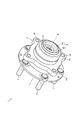
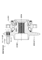
まず、図1から図4を用いて、本発明に係る車輪用軸受装置1について説明する。図1は、車輪用軸受装置1を示す斜視図である。図2は、車輪用軸受装置1の構造を示す断面図である。図3および図4は、車輪用軸受装置1の一部構造を示す断面図である。 First, the wheel bearing device 1 according to the present invention will be described with reference to FIGS. 1 to 4. FIG. 1 is a perspective view showing a wheel bearing device 1. FIG. 2 is a sectional view showing the structure of the wheel bearing device 1. 3 and 4 are sectional views showing a partial structure of the wheel bearing device 1.
車輪用軸受装置1は、車輪を回転自在に支持するものである。車輪用軸受装置1は、外方部材2と、内方部材3と、転動体4と、インナー側シール部材5と、アウター側シール部材6と、を備える。なお、本明細書において、「インナー側」とは、車体に取り付けた際の車輪用軸受装置1の車体側を表し、「アウター側」とは、車体に取り付けた際の車輪用軸受装置1の車輪側を表す。
The wheel bearing device 1 supports a wheel rotatably. The wheel bearing device 1 includes an outer member 2, an
外方部材2は、転がり軸受構造の外輪部分を構成するものである。外方部材2は、例えばS53C等の中高炭素鋼で構成されている。外方部材2のインナー側端部には、封止面2aが形成されている。また、外方部材2のアウター側端部には、封止面2bが形成されている。更に、外方部材2の内周には、二つの外側転走面2c・2dが形成されている。外側転走面2cは、後述する内側転走面3cに対向する。外側転走面2dは、後述する内側転走面3dに対向する。なお、外側転走面2c・2dには、例えば、高周波焼入れが施され、表面硬度が58〜64HRCの範囲となっている。加えて、外方部材2の外周には、ナックル取付フランジ2eが一体的に形成されている。ナックル取付フランジ2eには、複数のボルト穴2fが設けられている。
The outer member 2 constitutes the outer ring portion of the rolling bearing structure. The outer member 2 is made of medium-high carbon steel such as S53C, for example. A
内方部材3は、転がり軸受構造の内輪部分を構成するものである。内方部材3は、ハブ輪31と内輪32で構成されている。
The
ハブ輪31は、例えばS53C等の中高炭素鋼で構成されている。ハブ輪31には、そのインナー側端部から軸方向中央部まで小径段部3aが形成されている。小径段部3aは、ハブ輪31の外径が小さくなった部分を指し、その外周面が回転軸Aを中心とする円筒形状となっている。また、ハブ輪31には、そのインナー側端部からアウター側端部まで貫かれた自在継手取付穴3bが形成されている。自在継手取付穴3bは、ハブ輪31の中心に設けられた貫通穴を指し、その内周面における一部が凹部と凸部が交互に並ぶ凹凸形状(スプライン穴)となっている。更に、ハブ輪31の外周には、内側転走面3cが形成されている。内側転走面3cは、前述した外側転走面2cに対向する。なお、小径段部3aから内側転走面3cを経てシールランド部(後述する軸面部3eと曲面部3fと側面部3gで構成される)までには、例えば、高周波焼入れが施され、表面硬度が58〜64HRCの範囲となっている。加えて、ハブ輪31の外周には、車輪取付フランジ3hが一体的に形成されている。車輪取付フランジ3hには、複数のボルト穴3iが設けられ、それぞれのボルト穴3iにハブボルト7が圧入されている。ハブボルト7の詳細については後述する。
The
内輪32は、例えばSUJ2等の高炭素クロム軸受鋼で構成されている。内輪32の外周には、封止面3jが形成されている。また、内輪32の外周には、内側転走面3dが形成されている。内輪32は、ハブ輪31の小径段部3aに嵌合(外嵌)されることにより、ハブ輪31の外周に内側転走面3dを構成する。内側転走面3dは、前述した内側転走面2dに対向する。なお、内輪32は、例えば、いわゆるズブ焼入れが施され、芯部まで58〜64HRCの範囲となっている。
The
転動体4は、転がり軸受構造の転動部分を構成するものである。転動体4は、例えばSUJ2等の高炭素クロム軸受鋼で構成されている。インナー側の転動体列4Rは、複数の転動体4が保持器によって環状に配置されたものである。それぞれの転動体4は、外方部材2の外側転走面2dと内方部材3の内側転走面3dの間に転動自在に介装されている。一方で、アウター側の転動体列4Rも、複数の転動体4が保持器によって環状に配置されたものである。それぞれの転動体4は、外方部材2の外側転走面2cと内方部材3の内側転走面3cの間に転動自在に介装されている。なお、転動体4は、例えば、いわゆるズブ焼入れが施され、芯部まで62〜67HRCの範囲となっている。
The rolling
インナー側シール部材5は、外方部材2と内方部材3の間に形成された環状空間Sのインナー側端部を密封するものである。但し、インナー側シール部材5については、様々な仕様が存在しており、本願の仕様に限定するものではない。また、インナー側シール部材5の代わりにキャップが取り付けられる仕様や何も取り付けられない仕様も存在する。
The inner
インナー側シール部材5は、スリンガ51を含んでいる。スリンガ51は、内輪32の封止面3jに嵌合(外嵌)される。スリンガ51は、例えば、SUS430やSUS304等のステンレス鋼板、あるいはSPCC等の冷間圧延鋼板で構成されている。スリンガ51は、円環状の鋼板がプレス加工によって変形され、軸方向断面が略L字状に折り曲げられた形状となっている。これにより、スリンガ51は、円筒状の嵌合部51aと、その端部から外輪2に向かって延びる円板状の側板部51bと、が形成されている。
The inner
インナー側シール部材5は、シールリング52を含んでいる。シールリング52は、外輪2の嵌合部2aに嵌合(内嵌)される。シールリング52は、芯金53と弾性部材54で構成されている。芯金53は、例えば、SUS430やSUS304等のステンレス鋼板、あるいはSPCC等の冷間圧延鋼板で構成されている。芯金53は、円環状の鋼板がプレス加工によって変形され、軸方向断面が略L字状に折り曲げられた形状となっている。これにより、芯金53は、円筒状の嵌合部53aと、その端部から内輪32に向かって延びる円板状の側板部53bと、が形成されている。なお、嵌合部53aと側板部53bには、弾性部材54が例えば加硫接着により一体的に形成されている。
The inner
弾性部材54は、例えば、NBR(アクリロニトリル−ブタジエンゴム)、HNBR(水素化アクリロニトリル・ブタジエンゴム)、EPDM(エチレンプロピレンゴム)、ACM(ポリアクリルゴム)、FKM(フッ素ゴム)、あるいはシリコンゴム等の合成ゴムで構成されている。弾性部材54に形成されたシールリップ54aは、その先端部分がスリンガ51の嵌合部51aに接触している。また、シールリップ54b・54cは、その先端部分がスリンガ51の側板部51bに接触している。このようにして、インナー側シール部材5は、泥水や砂塵等の異物が環状空間Sに侵入するのを防ぐとともに、グリースが環状空間Sから漏出するのを防いでいる。
The
アウター側シール部材6は、外方部材2と内方部材3の間に形成された環状空間Sのアウター側端部を密封するものである。但し、アウター側シール部材6については、様々な仕様が存在しており、本願の仕様に限定するものではない。
The outer
アウター側シール部材6は、外輪2の嵌合部2bに嵌合(内嵌)される。アウター側シール部材6は、芯金62と弾性部材63で構成されている。芯金62は、例えば、SUS430やSUS304等のステンレス鋼板、あるいはSPCC等の冷間圧延鋼板で構成されている。芯金62は、円環状の鋼板がプレス加工によって変形され、軸方向断面が略L字状に折り曲げられた形状となっている。これにより、芯金62は、円筒状の嵌合部62aと、その端部からハブ輪31に向かって延びる円板状の側板部62bと、が形成されている。なお、側板部62bには、弾性部材63が例えば加硫接着により一体的に形成されている。
The outer
弾性部材63は、例えば、NBR(アクリロニトリル−ブタジエンゴム)、HNBR(水素化アクリロニトリル・ブタジエンゴム)、EPDM(エチレンプロピレンゴム)、ACM(ポリアクリルゴム)、FKM(フッ素ゴム)、あるいはシリコンゴム等の合成ゴムで構成されている。弾性部材63に形成されたシールリップ63aは、その先端部分がハブ輪31の軸面部3eに接触している。また、シールリップ63bは、その先端部分がハブ輪31の曲面部3fに接触している。更に、シールリップ63cは、その先端部分がハブ輪31の側面部3gに接触している。このようにして、アウター側シール部材6は、泥水や砂塵等の異物が環状空間Sに侵入するのを防ぐとともに、グリースが環状空間Sから漏出するのを防いでいるのである。
The elastic member 63 is, for example, NBR (acrylonitrile-butadiene rubber), HNBR (hydrogenated acrylonitrile-butadiene rubber), EPDM (ethylene propylene rubber), ACM (polyacrylic rubber), FKM (fluororubber), or silicon rubber. Consists of synthetic rubber. The tip of the
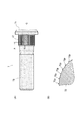
次に、図5および図6を用いて、ハブボルト7の特徴点について説明する。図5は、ハブボルト7の形状を示す図である。図5の(A)は、ハブボルト7の側面図であり、図5の(B)は、(A)におけるX−X部分に相当する断面図である。また、図6は、ハブボルト7の製造工程を示す図である。図6の(A)から(E)は、ハブボルト7が完成するまでの大まかな流れを表している。同時に、図7を用いて、本願発明の効果について説明する。図7は、車輪取付フランジ3hのボルト穴3iにハブボルト7が圧入されている状況を示す図である。図7の(A)は、車輪取付フランジ3hのボルト穴3iにハブボルト7が圧入されている状況を示す断面図であり、図7の(B)は、(A)におけるX−X部分に相当する断面図である。なお、本明細書において、「径方向外側」とは、ハブボルト7の中心軸Cから遠ざかる方向を表す。
Next, characteristic points of the
上述したように、ハブボルト7は、車輪取付フランジ3hに車輪を固定するものである。ハブボルト7は、SCr430等のクロム鋼若しくはSCM435等のクロム−モリブデン鋼で構成されている。ハブボルト7は、素材である鋼棒が軸方向に押圧され、これによって頭部71が形成される(図6の(A)参照)。そして、セレーション形成用のダイスDaに圧入されることで、軸体の大径部分にセレーション部72が形成され(図6の(B)参照)、更にネジ形成用のダイスDbに挟まれて回転されることで、軸体の小径部分にネジ部73が形成される(図6の(C)参照)。その後、ハブボルト7は、加熱炉Hoに投入され、浸炭焼入れが施される(図6の(D)参照)。これにより、ハブボルト7の表面硬度は、560〜600HVの範囲となる。加えて、ハブボルト7は、セレーション部72にのみショットピーニングによる表面硬化処理が施される(図6の(E)における※印部参照)。これにより、セレーション部72の表面硬度は、表面から20μm〜30μmの深さまで1000〜1100HVの範囲となる。こうすることで、疲労強度が高く、耐応力腐食割れ性が良好であるハブボルト7が完成する。
As described above, the
ここで、ショットピーニングによる表面硬化処理ついて簡単に説明する。ショットピーニングは、被加工物の表面を硬化させ、かつ圧縮残留応力を保持させる表面加工方法である。具体的に説明すると、投射材と呼ばれる粒状物を投射することにより、被加工物であるハブボルト7のセレーション部72表面を塑性変形させて硬化層を形成する。このとき、変形部分が戻ろうとする弾性力を周囲部分が拘束するので、セレーション部72表面に圧縮残留応力が保持されるのである。このような表面加工方法を実施することにより、セレーション部72の表面硬度を高めるとともに圧縮残留応力を保持させることができ、疲労強度の向上や耐応力腐食割れ性の向上を実現している。なお、投射材の大きさや投射速度等は、得られる特性に影響を及ぼすものであるが、これらについては限定するものではない。
Here, the surface hardening process by shot peening will be briefly described. Shot peening is a surface processing method that hardens the surface of a workpiece and maintains compressive residual stress. Specifically, by projecting a granular material called a projecting material, the surface of the
加えて、セレーション部72の形状について簡単に説明する。セレーション部72は、車輪取付フランジ3hのボルト穴3iに圧入される大径部分を指し、中心軸Cに沿う複数の突起72pが設けられ、それぞれ隣り合う突起72pが互いに等間隔である凹凸形状(セレーション軸)となっている。本ハブボルト7において、セレーション部72は、それぞれの突起72pの断面が径方向外側に尖った先鋭形状(くさび型形状)となっている(図5の(C)参照)。そのため、突起72pは、ハブボルト7を圧入する際に、ボルト穴3iの内周面3kに食い込むこととなる(図7の(A)および(B)参照)。なお、本車輪用軸受装置1においては、車輪取付フランジ3hが炭素鋼で形成されるのに対し、ハブボルト7がクロム鋼若しくはクロム−モリブデン鋼で形成され、そのセレーション部72の表面硬度が1000〜1100HVであることから、ボルト穴3iの内周面3k全周で突起72pが潰れずに食い込むこととなる。加えて、セレーション部72の突起72pが先鋭形状であることからも、ボルト穴3iの内周面3k全周で突起72pが深く安定的に食い込むこととなる。
In addition, the shape of the
以上のように、本願発明に係る車輪用軸受装置1は、ボルト穴3iに圧入されるハブボルト7を具備している。そして、ハブボルト7は、セレーション部72にショットピーニングによる表面硬化処理が施されている。かかる車輪用軸受装置1によれば、表面硬度の差により、ボルト穴3iの内周面3kにセレーション部72の突起72pが食い込むので、ハブボルト7の空回りを防ぐことができる。また、全てのボルト穴3iの内周面3k全周で突起72pが食い込むので、ボルト穴3i周辺の歪が偏らずに車輪取付フランジ3hの変形を抑制でき、ひいては車輪取付フランジ3hの回転振れを低減できる。
As described above, the wheel bearing device 1 according to the present invention includes the
また、本車輪用軸受装置1は、車輪取付フランジ3hが炭素鋼で形成されており、ハブボルト7がクロム鋼又はクロム−モリブデン鋼で形成されている。そして、セレーション部72は、表面硬度が1000HVから1100HVとなっている。かかる車輪用軸受装置1によれば、表面硬度の大きな差により、ボルト穴3iの内周面3kにセレーション部72の突起72pが潰れずに深く食い込むので、ハブボルト7の空回りを確実に防ぐことができる。また、全てのボルト穴3iの内周面3k全周で突起72pが潰れずに安定的に食い込むので、ボルト穴3i周辺の歪が偏らずに車輪取付フランジ3hの変形を確実に抑制でき、ひいては車輪取付フランジ3hの回転振れを確実に低減できる。
In the wheel bearing device 1, the
更に、本車輪用軸受装置1において、セレーション部72は、それぞれの突起72pの断面が径方向外側に尖った先鋭形状となっている。かかる車輪用軸受装置1によれば、ボルト穴3iの内周面3kにセレーション部72の突起72pが深く食い込むので、ハブボルト7の空回りを確実に防ぐことができる。また、全てのボルト穴3iの内周面3k全周で突起72pが安定的に食い込むので、ボルト穴3i周辺の歪が偏らずに車輪取付フランジ3hの変形を確実に抑制でき、ひいては車輪取付フランジ3hの回転振れを確実に低減できる。
Further, in the wheel bearing device 1, the
本願発明に係る車輪用軸受装置1は、内方部材3として一つの内輪32が嵌合されたハブ輪31を備え、ナックル取付フランジを有している外方部材2と内方部材3である内輪31とハブ輪32の嵌合体で構成された内輪回転仕様の第3世代構造としているが、これに限定するものではない。例えば、内方部材として一つの内輪が嵌合された支持軸を備え、外方部材がハブ輪として形成されており、この外方部材であるハブ輪と内方部材である内輪と支持軸の嵌合体で構成された外輪回転仕様の第3世代構造であってもよい。更に、ナックル取付フランジを有している外方部材と内方部材である一対の内輪で構成され、この一対の内輪がハブ輪の外周に嵌合される内輪回転仕様の第2世代構造であってもよい。また、外方部材がハブ輪として形成されており、この外方部材であるハブ輪と内方部材である一対の内輪で構成された外輪回転仕様の第2世代構造であってもよい。更に、外方部材である外輪と内方部材である一対の内輪で構成され、外輪がハウジングの内周に嵌合される第1世代構造であってもよい。
The wheel bearing device 1 according to the present invention includes an outer member 2 and an
1 車輪用軸受装置
2 外方部材
2c 外側転走面
2d 外側転走面
3 内方部材
31 ハブ輪
32 内輪
3c 内側転走面
3d 内側転走面
3h 車輪取付フランジ
3i ボルト穴
3k 内周面
4 転動体
7 ハブボルト
71 頭部
72 セレーション部
72p 突起
73 ネジ部
A 回転軸
C 中心軸
DESCRIPTION OF SYMBOLS 1 Wheel bearing apparatus 2
Claims (3)
外周に内側転走面が形成された内方部材と、
前記外方部材と前記内方部材のそれぞれの転走面間に介装される複数の転動体と、を備え、
前記外方部材若しくは前記内方部材のいずれか一方に車輪取付フランジが形成されるとともに、当該車輪取付フランジの回転軸を中心とする同心円上に複数のボルト穴が設けられている車輪用軸受装置において、
前記ボルト穴に圧入されるハブボルトを具備し、
前記ハブボルトは、セレーション部にショットピーニングによる表面硬化処理が施されている、ことを特徴とする車輪用軸受装置。 An outer member having an outer rolling surface formed on the inner periphery;
An inner member having an inner rolling surface formed on the outer periphery;
A plurality of rolling elements interposed between the rolling surfaces of the outer member and the inner member,
A wheel bearing device in which a wheel mounting flange is formed on one of the outer member and the inner member, and a plurality of bolt holes are provided on concentric circles centering on the rotation axis of the wheel mounting flange. In
Comprising a hub bolt press-fitted into the bolt hole;
The hub bolt is a bearing device for wheels, wherein the serration portion is subjected to surface hardening treatment by shot peening.
前記ハブボルトがクロム鋼若しくはクロム−モリブデン鋼で形成されており、
前記セレーション部は、表面硬度が1000HVから1100HVとなっている、ことを特徴とする請求項1に記載の車輪用軸受装置。 The wheel mounting flange is formed of carbon steel;
The hub bolt is formed of chromium steel or chromium-molybdenum steel;
2. The wheel bearing device according to claim 1, wherein the serration portion has a surface hardness of 1000 HV to 1100 HV.
Priority Applications (1)
| Application Number | Priority Date | Filing Date | Title |
|---|---|---|---|
| JP2017051992A JP2018154209A (en) | 2017-03-16 | 2017-03-16 | Bearing device for wheel |
Applications Claiming Priority (1)
| Application Number | Priority Date | Filing Date | Title |
|---|---|---|---|
| JP2017051992A JP2018154209A (en) | 2017-03-16 | 2017-03-16 | Bearing device for wheel |
Publications (1)
| Publication Number | Publication Date |
|---|---|
| JP2018154209A true JP2018154209A (en) | 2018-10-04 |
Family
ID=63715497
Family Applications (1)
| Application Number | Title | Priority Date | Filing Date |
|---|---|---|---|
| JP2017051992A Pending JP2018154209A (en) | 2017-03-16 | 2017-03-16 | Bearing device for wheel |
Country Status (1)
| Country | Link |
|---|---|
| JP (1) | JP2018154209A (en) |
Cited By (1)
| Publication number | Priority date | Publication date | Assignee | Title |
|---|---|---|---|---|
| CN111519009A (en) * | 2020-05-11 | 2020-08-11 | 中航飞机起落架有限责任公司 | Pneumatic shot blasting part surface strengthening device |
-
2017
- 2017-03-16 JP JP2017051992A patent/JP2018154209A/en active Pending
Cited By (1)
| Publication number | Priority date | Publication date | Assignee | Title |
|---|---|---|---|---|
| CN111519009A (en) * | 2020-05-11 | 2020-08-11 | 中航飞机起落架有限责任公司 | Pneumatic shot blasting part surface strengthening device |
Similar Documents
| Publication | Publication Date | Title |
|---|---|---|
| JP7260581B2 (en) | Bearing device for wheel and manufacturing method thereof | |
| JP2015158226A (en) | Sealing device and wheel bearing device having the same | |
| JP2015183801A (en) | wheel bearing device | |
| JP2018154209A (en) | Bearing device for wheel | |
| JP5166757B2 (en) | Wheel bearing and wheel bearing device provided with the same | |
| JP2014020404A (en) | Wheel bearing device | |
| JP2017133573A (en) | Wheel bearing device | |
| JP7021844B2 (en) | Wheel bearing equipment and its manufacturing method | |
| US11125270B2 (en) | Bearing device for wheel | |
| JP6709635B2 (en) | Wheel bearing device | |
| JP6860309B2 (en) | Bearing device for wheels | |
| JP2017067103A (en) | Bearing device for wheel | |
| JP2017187081A (en) | Bearing device for wheel | |
| JP6448693B2 (en) | Wheel bearing device | |
| JP6788441B2 (en) | Bearing device for wheels | |
| JP2018044572A (en) | Bearing device for wheel | |
| JP2013166487A (en) | Bearing device for wheel | |
| JP6848350B2 (en) | Bearing device for wheels | |
| JP2018096478A (en) | Wheel bearing device | |
| JP6920083B2 (en) | Bearing device for wheels | |
| JP2010105472A (en) | Bearing device for wheel | |
| JP6725993B2 (en) | Wheel bearing device | |
| JP6721974B2 (en) | Wheel bearing device | |
| JP2020023976A (en) | Hub unit bearing | |
| JP2017128237A (en) | Wheel bearing device |
Legal Events
| Date | Code | Title | Description |
|---|---|---|---|
| A621 | Written request for application examination |
Free format text: JAPANESE INTERMEDIATE CODE: A621 Effective date: 20200226 |
|
| A977 | Report on retrieval |
Free format text: JAPANESE INTERMEDIATE CODE: A971007 Effective date: 20201224 |
|
| A131 | Notification of reasons for refusal |
Free format text: JAPANESE INTERMEDIATE CODE: A131 Effective date: 20210105 |
|
| A02 | Decision of refusal |
Free format text: JAPANESE INTERMEDIATE CODE: A02 Effective date: 20210608 |