JP2018136533A - Image forming device - Google Patents
Image forming device Download PDFInfo
- Publication number
- JP2018136533A JP2018136533A JP2018019619A JP2018019619A JP2018136533A JP 2018136533 A JP2018136533 A JP 2018136533A JP 2018019619 A JP2018019619 A JP 2018019619A JP 2018019619 A JP2018019619 A JP 2018019619A JP 2018136533 A JP2018136533 A JP 2018136533A
- Authority
- JP
- Japan
- Prior art keywords
- developer
- cartridge
- amount
- toner
- cleaning
- Prior art date
- Legal status (The legal status is an assumption and is not a legal conclusion. Google has not performed a legal analysis and makes no representation as to the accuracy of the status listed.)
- Pending
Links
Images


Classifications
-
- G—PHYSICS
- G03—PHOTOGRAPHY; CINEMATOGRAPHY; ANALOGOUS TECHNIQUES USING WAVES OTHER THAN OPTICAL WAVES; ELECTROGRAPHY; HOLOGRAPHY
- G03G—ELECTROGRAPHY; ELECTROPHOTOGRAPHY; MAGNETOGRAPHY
- G03G15/00—Apparatus for electrographic processes using a charge pattern
- G03G15/06—Apparatus for electrographic processes using a charge pattern for developing
- G03G15/08—Apparatus for electrographic processes using a charge pattern for developing using a solid developer, e.g. powder developer
- G03G15/0822—Arrangements for preparing, mixing, supplying or dispensing developer
- G03G15/0844—Arrangements for purging used developer from the developing unit
-
- G—PHYSICS
- G03—PHOTOGRAPHY; CINEMATOGRAPHY; ANALOGOUS TECHNIQUES USING WAVES OTHER THAN OPTICAL WAVES; ELECTROGRAPHY; HOLOGRAPHY
- G03G—ELECTROGRAPHY; ELECTROPHOTOGRAPHY; MAGNETOGRAPHY
- G03G15/00—Apparatus for electrographic processes using a charge pattern
- G03G15/55—Self-diagnostics; Malfunction or lifetime display
- G03G15/553—Monitoring or warning means for exhaustion or lifetime end of consumables, e.g. indication of insufficient copy sheet quantity for a job
- G03G15/556—Monitoring or warning means for exhaustion or lifetime end of consumables, e.g. indication of insufficient copy sheet quantity for a job for toner consumption, e.g. pixel counting, toner coverage detection or toner density measurement
-
- G—PHYSICS
- G03—PHOTOGRAPHY; CINEMATOGRAPHY; ANALOGOUS TECHNIQUES USING WAVES OTHER THAN OPTICAL WAVES; ELECTROGRAPHY; HOLOGRAPHY
- G03G—ELECTROGRAPHY; ELECTROPHOTOGRAPHY; MAGNETOGRAPHY
- G03G15/00—Apparatus for electrographic processes using a charge pattern
- G03G15/06—Apparatus for electrographic processes using a charge pattern for developing
- G03G15/08—Apparatus for electrographic processes using a charge pattern for developing using a solid developer, e.g. powder developer
- G03G15/0822—Arrangements for preparing, mixing, supplying or dispensing developer
- G03G15/0865—Arrangements for supplying new developer
-
- G—PHYSICS
- G03—PHOTOGRAPHY; CINEMATOGRAPHY; ANALOGOUS TECHNIQUES USING WAVES OTHER THAN OPTICAL WAVES; ELECTROGRAPHY; HOLOGRAPHY
- G03G—ELECTROGRAPHY; ELECTROPHOTOGRAPHY; MAGNETOGRAPHY
- G03G15/00—Apparatus for electrographic processes using a charge pattern
- G03G15/50—Machine control of apparatus for electrographic processes using a charge pattern, e.g. regulating differents parts of the machine, multimode copiers, microprocessor control
- G03G15/5062—Machine control of apparatus for electrographic processes using a charge pattern, e.g. regulating differents parts of the machine, multimode copiers, microprocessor control by measuring the characteristics of an image on the copy material
-
- G—PHYSICS
- G03—PHOTOGRAPHY; CINEMATOGRAPHY; ANALOGOUS TECHNIQUES USING WAVES OTHER THAN OPTICAL WAVES; ELECTROGRAPHY; HOLOGRAPHY
- G03G—ELECTROGRAPHY; ELECTROPHOTOGRAPHY; MAGNETOGRAPHY
- G03G21/00—Arrangements not provided for by groups G03G13/00 - G03G19/00, e.g. cleaning, elimination of residual charge
- G03G21/0005—Arrangements not provided for by groups G03G13/00 - G03G19/00, e.g. cleaning, elimination of residual charge for removing solid developer or debris from the electrographic recording medium
- G03G21/0011—Arrangements not provided for by groups G03G13/00 - G03G19/00, e.g. cleaning, elimination of residual charge for removing solid developer or debris from the electrographic recording medium using a blade; Details of cleaning blades, e.g. blade shape, layer forming
-
- G—PHYSICS
- G03—PHOTOGRAPHY; CINEMATOGRAPHY; ANALOGOUS TECHNIQUES USING WAVES OTHER THAN OPTICAL WAVES; ELECTROGRAPHY; HOLOGRAPHY
- G03G—ELECTROGRAPHY; ELECTROPHOTOGRAPHY; MAGNETOGRAPHY
- G03G21/00—Arrangements not provided for by groups G03G13/00 - G03G19/00, e.g. cleaning, elimination of residual charge
- G03G21/0094—Arrangements not provided for by groups G03G13/00 - G03G19/00, e.g. cleaning, elimination of residual charge fatigue treatment of the photoconductor
-
- G—PHYSICS
- G03—PHOTOGRAPHY; CINEMATOGRAPHY; ANALOGOUS TECHNIQUES USING WAVES OTHER THAN OPTICAL WAVES; ELECTROGRAPHY; HOLOGRAPHY
- G03G—ELECTROGRAPHY; ELECTROPHOTOGRAPHY; MAGNETOGRAPHY
- G03G21/00—Arrangements not provided for by groups G03G13/00 - G03G19/00, e.g. cleaning, elimination of residual charge
- G03G21/10—Collecting or recycling waste developer
- G03G21/12—Toner waste containers
-
- G—PHYSICS
- G03—PHOTOGRAPHY; CINEMATOGRAPHY; ANALOGOUS TECHNIQUES USING WAVES OTHER THAN OPTICAL WAVES; ELECTROGRAPHY; HOLOGRAPHY
- G03G—ELECTROGRAPHY; ELECTROPHOTOGRAPHY; MAGNETOGRAPHY
- G03G21/00—Arrangements not provided for by groups G03G13/00 - G03G19/00, e.g. cleaning, elimination of residual charge
- G03G21/16—Mechanical means for facilitating the maintenance of the apparatus, e.g. modular arrangements
- G03G21/18—Mechanical means for facilitating the maintenance of the apparatus, e.g. modular arrangements using a processing cartridge, whereby the process cartridge comprises at least two image processing means in a single unit
- G03G21/1803—Arrangements or disposition of the complete process cartridge or parts thereof
- G03G21/1814—Details of parts of process cartridge, e.g. for charging, transfer, cleaning, developing
-
- G—PHYSICS
- G03—PHOTOGRAPHY; CINEMATOGRAPHY; ANALOGOUS TECHNIQUES USING WAVES OTHER THAN OPTICAL WAVES; ELECTROGRAPHY; HOLOGRAPHY
- G03G—ELECTROGRAPHY; ELECTROPHOTOGRAPHY; MAGNETOGRAPHY
- G03G15/00—Apparatus for electrographic processes using a charge pattern
- G03G15/50—Machine control of apparatus for electrographic processes using a charge pattern, e.g. regulating differents parts of the machine, multimode copiers, microprocessor control
-
- G—PHYSICS
- G03—PHOTOGRAPHY; CINEMATOGRAPHY; ANALOGOUS TECHNIQUES USING WAVES OTHER THAN OPTICAL WAVES; ELECTROGRAPHY; HOLOGRAPHY
- G03G—ELECTROGRAPHY; ELECTROPHOTOGRAPHY; MAGNETOGRAPHY
- G03G2215/00—Apparatus for electrophotographic processes
- G03G2215/06—Developing structures, details
- G03G2215/066—Toner cartridge or other attachable and detachable container for supplying developer material to replace the used material
-
- G—PHYSICS
- G03—PHOTOGRAPHY; CINEMATOGRAPHY; ANALOGOUS TECHNIQUES USING WAVES OTHER THAN OPTICAL WAVES; ELECTROGRAPHY; HOLOGRAPHY
- G03G—ELECTROGRAPHY; ELECTROPHOTOGRAPHY; MAGNETOGRAPHY
- G03G2221/00—Processes not provided for by group G03G2215/00, e.g. cleaning or residual charge elimination
- G03G2221/16—Mechanical means for facilitating the maintenance of the apparatus, e.g. modular arrangements and complete machine concepts
- G03G2221/18—Cartridge systems
- G03G2221/183—Process cartridge
- G03G2221/1838—Autosetting of process parameters
Abstract
Description
本発明は、記録材上に画像を形成する画像形成装置に関するものである。 The present invention relates to an image forming apparatus that forms an image on a recording material.
本発明は、電子写真方式や静電記録方式を用いた複写機、プリンタ、ファクシミリ装置などの画像形成装置に関するものである。 The present invention relates to an image forming apparatus such as a copying machine, a printer, or a facsimile apparatus using an electrophotographic system or an electrostatic recording system.
画像形成装置には、メンテナンスを容易にするために、現像部分を着脱可能な現像カートリッジとして構成する場合や、像担持体とそのプロセスを一体としたプロセスカートリッジとして構成する場合がある。 In order to facilitate maintenance, the image forming apparatus may be configured as a developing cartridge in which the developing portion is detachable or may be configured as a process cartridge in which the image carrier and its process are integrated.
また、像担持体上に形成された現像剤像が記録材上に転写した後に残存する現像剤を除去する手段として、像担持体の表面に対してクリーニング部材を当接させて除去する手段が知られている。クリーニング部材としては、ウレタンゴム等から構成される弾性体と弾性体を支持する支持板金からなる構成が広く採用されている。 Further, as a means for removing the developer remaining after the developer image formed on the image carrier is transferred onto the recording material, a means for removing the developer by bringing the cleaning member into contact with the surface of the image carrier. Are known. As the cleaning member, a configuration composed of an elastic body made of urethane rubber or the like and a support sheet metal that supports the elastic body is widely adopted.
この構成では、クリーニング部材と像担持体の表面との間の摩擦力が上昇することでクリーニング部材の挙動が不安定になり、クリーニング部材の捲れやビビり振動による異音が発生することがあった(特許文献1)。 In this configuration, the frictional force between the cleaning member and the surface of the image carrier increases, so that the behavior of the cleaning member becomes unstable, and abnormal noise may occur due to the cleaning member being swung or chatter vibration. (Patent Document 1).
特許文献1では、これらの課題への対応として、現像装置側から像担持体を介してクリーニング部材に現像剤を供給し、両者の摩擦力を低減して潤滑性を保つ方法が提案されている。 Japanese Patent Application Laid-Open No. H10-228867 proposes a method for supplying the developer to the cleaning member from the developing device side via the image carrier and reducing the frictional force between the two to maintain the lubricity. .
特許文献1に記述された方法は、前述の課題を回避するために有力ではあるものの、クリーニング部材側に送り込まれた現像剤はクリーニング容器に回収されてしまうため、画像形成に使用することができない。このため、クリーニング部材に送り込まれる現像剤の量が増えると、その分だけユーザが印字できるプリント枚数が減ってしまう。 Although the method described in Patent Document 1 is effective for avoiding the above-described problems, the developer sent to the cleaning member side is collected in the cleaning container and cannot be used for image formation. . For this reason, when the amount of the developer fed to the cleaning member increases, the number of prints that can be printed by the user decreases accordingly.
本発明の目的は、クリーニング部材に送り込む現像剤の量を低減できる画像形成装置を提供することである。 An object of the present invention is to provide an image forming apparatus capable of reducing the amount of developer fed to a cleaning member.
そこで、本発明における画像形成装置は、像担持体と、前記像担持体と接触して前記像担持体をクリーニングするクリーニング部材と、を有するクリーニングカートリッジと、現像剤を前記像担持体に搬送する現像剤担持体を有する現像カートリッジと、を有し、前記クリーニングカートリッジと前記現像カートリッジとは画像形成装置の装置本体に対して、それぞれ着脱可能な画像形成装置であって、非画像形成時に前記現像カートリッジから前記像担持体を介して前記クリーニング部材に前記現像剤が供給される現像剤の供給工程を実行する制御部を有し、前記制御部は、前記現像剤の供給工程で前記現像カートリッジから前記クリーニング部材に供給される前記現像剤の供給量を、前記クリーニング部材で回収された現像剤量に係る値と前記現像カートリッジの使用量に係る値とに基づいて、決定することを特徴とする。 Accordingly, an image forming apparatus according to the present invention conveys a developer to the image carrier, a cleaning cartridge having an image carrier, and a cleaning member that contacts the image carrier and cleans the image carrier. A developing cartridge having a developer carrying member, wherein the cleaning cartridge and the developing cartridge are each an image forming apparatus that can be attached to and detached from an apparatus main body of the image forming apparatus. A control unit that executes a developer supplying step in which the developer is supplied from the cartridge to the cleaning member via the image carrier, and the control unit removes the developer from the developing cartridge in the developer supplying step. The supply amount of the developer supplied to the cleaning member is a value related to the developer amount collected by the cleaning member. Based on the value of the amount of the developer cartridge, and determining.
或いは、本発明における画像形成装置は、像担持体と、前記像担持体と接触して前記像担持体をクリーニングするクリーニング部材と、現像剤を前記像担持体に搬送する現像剤担持体と、を有するプロセスカートリッジと、前記現像剤担持体に現像剤を供給するためのトナーカートリッジと、を有し、画像形成装置の装置本体に対して前記プロセスカートリッジが着脱可能な画像形成装置であって、非画像形成時に前記現像剤担持体から前記像担持体を介して前記クリーニング部材に前記現像剤が供給される現像剤の供給工程を実行する制御部を有し、前記制御部は、前記現像剤の供給工程で前記現像剤担持体から前記クリーニング部材に供給される前記現像剤の供給量を、前記クリーニング部材で回収された現像剤量に係る値と前記トナーカートリッジの使用量に係る値とに基づいて決定することを特徴とする。 Alternatively, an image forming apparatus according to the present invention includes an image carrier, a cleaning member that contacts the image carrier and cleans the image carrier, a developer carrier that transports the developer to the image carrier, and An image forming apparatus, and a toner cartridge for supplying a developer to the developer carrying member, wherein the process cartridge is detachable from an apparatus main body of the image forming apparatus, A control unit that executes a developer supplying step in which the developer is supplied from the developer carrier to the cleaning member via the image carrier during non-image formation, and the controller includes the developer The supply amount of the developer supplied from the developer carrying member to the cleaning member in the supply step is a value related to the developer amount collected by the cleaning member and the toner. And determining based on the value relating to the amount of cartridges.
本発明によれば、クリーニング部材に送り込む現像剤の量を低減できる画像形成装置を提供することである。 According to the present invention, it is an object to provide an image forming apparatus capable of reducing the amount of developer fed to a cleaning member.
以下、図面を参照して本実施例の形態を例示する。ただし、本実施例に記載されている構成部品の寸法、材質、形状、それらの相対配置などは、本発明が適用される装置の構成や各種条件により適宜変更されるべきものであり、本発明の範囲を以下の実施形態に限定する趣旨のものではない。 Hereinafter, the form of a present Example is illustrated with reference to drawings. However, the dimensions, materials, shapes, relative arrangements, and the like of the component parts described in this embodiment should be changed as appropriate according to the configuration of the apparatus to which the present invention is applied and various conditions. It is not intended that the scope of the present invention be limited to the following embodiments.
<画像形成装置>
実施例1に係る画像形成装置の構成を、図1を用いて説明する。
<Image forming apparatus>
The configuration of the image forming apparatus according to the first embodiment will be described with reference to FIG.
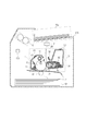
本実施例の画像形成装置は、画像形成装置の装置本体100内に少なくともクリーニングカートリッジ(感光体ユニット)1、露光装置2、現像カートリッジ(現像ユニット)3、転写装置4、定着装置5を備えている。また、クリーニングカートリッジ(感光体ユニット)1と現像カートリッジ(現像ユニット)3は、各々が独立して装置本体100から着脱可能となっている。
The image forming apparatus according to the present exemplary embodiment includes at least a cleaning cartridge (photosensitive unit) 1, an
クリーニングカートリッジ1は、像担持体である感光ドラム10、帯電部材である帯電ローラ11、クリーニング部材であるクリーニングブレード12、記憶素子13を有する。本実施例では、2体のカートリッジであるため、クリーニングカートリッジが有する記憶素子13を第1記憶素子とし、後述する現像カートリッジ3の記憶素子37を第2記憶素子とする。
The cleaning cartridge 1 includes a
本実施例の現像カートリッジ3は、画像形成に用いられる負帯電性の一成分現像剤30(以下、「トナー」と称す)を有する。そして、現像カートリッジ3は、現像剤担持体である現像ローラ31、現像剤規制部材である現像ブレード32、現像剤担持体へのトナーの供給を行う供給ローラ33、不揮発性メモリなどの記憶素子37を有する。
The developing cartridge 3 of this embodiment has a negatively chargeable one-component developer 30 (hereinafter referred to as “toner”) used for image formation. The developing cartridge 3 includes a developing
制御部103は、演算処理を行う中心的素子であるCPU(中央演算処理ユニット)、記憶素子であるROM、RAMなどのメモリ1などを有して構成される。RAMには、センサーの検知結果、演算結果などが格納され、ROMには制御プログラム、予め求められたデータテーブルなどが格納されている。
The
制御部103は、装置本体100の動作を統括的に制御する制御手段であり、各種の電気的情報信号の授受や、駆動のタイミングなどを制御しており、後述するシーケンスなどを司る。制御部103には、装置本体100における各制御対象が接続されている。例えば、制御部103には、クリーニングカートリッジ1、現像カートリッジ4、露光装置2、転写装置4、定着装置5を動作させる駆動手段、電源部等、各種センサー出力ライン、記憶素子13、37等に電気的に接続されている。
The
本実施例では、クリーニングカートリッジ1と現像カートリッジ3を独立に着脱可能にすることで、ユーザは「トナーなし」が報知されたときは現像カートリッジ3だけを交換すればよい。同様に、「ドラム寿命」が報知されたときはクリーニングカートリッジ1だけを交換すればよい。このように構成されたため、各々のカートリッジを寿命まで効率的に使用できるメリットがある。像担持体の寿命が長くなったこともあり、1本のクリーニングカートリッジ1に対し、2〜5本程度の現像カートリッジ3が使用できる。 In this embodiment, the cleaning cartridge 1 and the developing cartridge 3 can be detached independently, so that the user only needs to replace the developing cartridge 3 when “no toner” is notified. Similarly, when the “drum life” is notified, only the cleaning cartridge 1 needs to be replaced. Since it comprised in this way, there exists a merit which can use each cartridge efficiently until the lifetime. Since the life of the image carrier is prolonged, about 2 to 5 developing cartridges 3 can be used for one cleaning cartridge 1.
<画像形成プロセス>
帯電ローラ11は、回転可能な円筒形の感光ドラム10表面に静電像(または静電潜像)を形成するための前処理として、感光ドラム表面を均一帯電する。帯電部材たる帯電ローラ11は回転軸を中心に回転可能であり、感光ドラム10に接触して従動回転する。帯電ローラ11には装置本体100内の帯電電圧印加手段から帯電電圧が印加され、これによって、感光ドラム10表面は一様に帯電される。
<Image formation process>
The
露光装置2は、均一帯電された感光ドラム10に静電潜像を形成する。露光部材としては、レーザダイオードやポリゴンミラー等を含むレーザビームスキャナを用いる。レーザビームスキャナは目的の画像情報の画素信号に対応して強度変調されたレーザ光21を出力し、感光ドラム10の帯電面を走査露光することで静電潜像が形成される。
The
現像装置である現像カートリッジ3は、現像枠体34内にトナー70を内包し、感光ドラム10表面に形成された静電潜像に対して、回転軸を中心に回転可能な現像ローラ31上のトナー70を搬送して現像動作を行う。現像ローラ31には現像電圧印加手段としての現像バイアス電源から現像電圧が印加されることで、現像剤が搬送され静電潜像は可視像化される。
The developing cartridge 3 that is a developing device includes a
転写装置4は、感光ドラム10表面のトナー像を記録材Pに転写するための装置である。トナー像の形成と同期して給紙カセット101から記録材Pが搬送され、転写バイアス電源により転写手段である転写ローラ41に対し所定の電圧印加を行う。転写ローラに印加された電圧により、感光ドラム10表面のトナー像を記録材Pへ転写させている。このとき、トナー像の大部分は記録材Pへ転写されるが、一部は記録材Pへ転写しきれずに感光ドラム10上に残存する。
The
定着装置5は、トナー像が転写された記録材Pを熱と圧力によって固定画像として記録材Pに定着させ、装置本体100外の排紙トレイ102上に排出され蓄積する。
The fixing
クリーニング部材であるクリーニングブレード12は、感光ドラム10に所定圧力で接触し、記録材Pへ転写しきれずに感光ドラム10上に残存したトナーを掻き落としてクリーニング枠体14内に蓄積する。これによって感光ドラム10表面はリフレッシュされる。
The
以降は、同様のプロセスが繰り返されることによって画像形成が継続される。 Thereafter, image formation is continued by repeating the same process.
<クリーニングカートリッジ>
次に、図2、3を用いて、実施例1に係るクリーニングカートリッジ1の構成について説明する。なお、図3においては、各部材の配置を説明するために、前面に位置する一部の部材については、部分的に切断して描写した。
<Cleaning cartridge>
Next, the configuration of the cleaning cartridge 1 according to the first embodiment will be described with reference to FIGS. In FIG. 3, in order to explain the arrangement of the members, some members located on the front surface are partially cut and depicted.
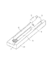
図2はクリーニングカートリッジ1の断面図である。 FIG. 2 is a sectional view of the cleaning cartridge 1.
感光ドラム10はφ24mmの負帯電性感光体が用いられ、感光ドラム10は矢印R1方向に回転可能であり、装置本体内の駆動モータにより表面速度100mm/secで回転駆動される。帯電ローラ11はφ6mmの芯金部11aと厚さ1mmのゴム層11bで構成され、芯金部11aを中心に回転可能であり、200〜600gfの力で両端から加圧され、感光ドラム10と当接している。装置本体内の帯電電圧印加手段から印加される帯電電圧は、感光ドラム10表面と帯電ローラ11との電位差が放電開始電圧以上となる値に設定されており、帯電電圧として−1000〜−1100Vの直流電圧を印加している。このとき、感光ドラム10の表面電位Vdは、Vd=−450Vに一様に帯電される。クリーニングブレード12は、厚さ2mm、23℃におけるMD−1硬度が60〜80ポイントのウレタンゴム12aが、クリーニング支持板金12bによって支持されて一体となり形成される。クリーニングブレード12は、クリーニング枠体14に固定され、ウレタンゴム12aの先端が70gf/cm程度の圧力で感光ドラム10に当接するよう設置されている。クリーニングブレード12はウレタンゴム12aの自由端の先端にて、転写されずに感光ドラム10の表面に残った転写残トナーを掻き取る。クリーニングブレード12によって掻き取られたトナー15(以下、「廃トナー」と表記)はクリーニング枠体14内に収容される。廃トナーの一部は、ウレタンゴム12aの自由端の先端に滞留し、感光ドラム10とウレタンゴム12aとの間に潤滑性を与え、クリーニング性を安定化させる。クリーニング枠体14に収容される廃トナー量は、印字される総画素数と使用環境から、転写効率とベタ白部へのカブリ量を予測することで算出され、この結果は記憶素子13に記録される。記憶素子13にはこの他に感光ドラム10の回転数や製造番号などの情報が記憶されており、記憶素子13が持つ情報によってクリーニングカートリッジ1の使用状況を把握できる。感光ドラム10の回転数やクリーニング枠体14に収容された廃トナー量が閾値を超えたとき、クリーニングカートリッジ1は寿命と判定され、これがユーザに報知され、新しいクリーニングカートリッジ1と交換される。クリーニングカートリッジ1の寿命は、像担持体である感光ドラム10の使用量をもとに算出してもよい。例えば、感光ドラム10の駆動時間や回転数をもとに、クリーニングカートリッジ1の寿命に対応する閾値を設定し、駆動時間や回転数が閾値を越えた場合に、クリーニングカートリッジが寿命であることを報知してもよい。このような場合は、クリーニングカートリッジ自身で廃トナーを収容せず、装置本体に別に廃トナー容器を備える構成の機種の場合が考えられる。
The
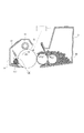
次に、図3を用いてクリーニング枠体14周囲の構成について説明する。クリーニングブレード12により感光ドラム10表面の残存トナーが掻き落とされる。掻き落とされたトナーは、クリーニング枠体14、すくいシート16、クリーニング端部シール17とで画定されたクリーニング開口18からクリーニング枠体14内に蓄積される。すくいシート16は、可撓性のシート部材であり、感光ドラム10とクリーニング端部シール17とに密接することで、クリーニング枠体14からのトナー洩れを防止する。クリーニング端部シール17は、感光ドラム10との当接面に微細な植毛処理を施した弾性部材であり、感光ドラム10、クリーニンブレード12、すくいシート16、およびクリーニング枠体14と密接する。密接することで、クリーニング枠体14端部からのトナー洩れを防止する。
Next, the configuration around the
<現像カートリッジ>
図4、5、6を用いて、実施例1に係る現像カートリッジ3の構成について説明する。なお、図6においては、各部材の配置を説明するために、前面に位置する一部の部材については、部分的に切断して描写している。
<Development cartridge>
The configuration of the developing cartridge 3 according to the first embodiment will be described with reference to FIGS. In FIG. 6, in order to explain the arrangement of each member, some members located on the front surface are partially cut and depicted.
トナー70は、負帯電性の非磁性一成分トナーを用いている。図5に示されるように、母体となる電荷制御剤や顔量等を含む樹脂粒子30aに潤滑剤や電荷制御剤等の無機微粒子である外添剤30bを添加した構成となっている。これらは図4に示されるように現像枠体34に内包(収容)されている。現像ローラ31は矢印R2の方向に回転可能なローラ部材であり、感光ドラム10上の静電潜像までトナー70を担持しながら搬送する役割を担っている。現像ブレード32はSUS平板であり、現像ローラ31に所定圧力で当接して現像ローラ31上のトナー量(またはトナーの層厚)を略一定に規制している。トナー量を規制するときの摩擦によってトナー70は負に帯電する。供給ローラ33はトナー70を含有可能なローラ部材であり、現像ローラ31に当接しながら矢印R3方向に回転する。回転することで、現像ローラ31表面にトナー70を供給する。吹き出し防止シート38は可撓性のシート部材であり、現像ローラ31および現像端部シール35に密接することで、現像枠体34からのトナー洩れを防止する。現像端部シール35は現像ローラ31との当接面に微細な植毛処理を施した弾性部材である。現像端部シール35は、現像ローラ31、現像ブレード32、吹き出し防止シート33、現像枠体34と、に密接することで、現像枠体34端部からのトナー洩れを防止する。
The
現像枠体34内の現像剤量であるトナー量を知るために、本実施例においては、露光装置2の発光する画素(ピクセル)数をカウントする(以下、「ピクセルカウント」と表記)ことが出来る計測手段を用いる。ある画素数の画像を現像するために要するトナー使用量は、発光するピクセル数から算出可能である。このため、ピクセルカウント方式を用いれば消費されたトナー量が算出され、この値を初期のトナー充填量から減算することで、現像枠体34内のトナー残量が算出される。この値は記憶素子37に記録される。記憶素子37には、トナー残量の他に現像ローラ31の回転数などが記憶されており、記憶素子37が持つ情報によって、現像カートリッジ3の使用状況を把握できる。現像ローラ31の回転数や残トナー量が閾値を超えたとき、現像カートリッジ3は寿命と判定され、これがユーザに報知されて、新しい現像カートリッジと交換される。
In this embodiment, in order to know the toner amount which is the developer amount in the developing
本実施例では、ピクセル数をカウントする方式を用いて、現像枠体34内に収容されて残っている現像剤量を算出しているが、この方式に限定されるものではない。例えば、現像枠体34内に光を通過させ、現像剤が存在すれば光が遮蔽されることにより現像剤量を判断する光残量検知方式ある。また、一対の電極を配置し、電極間に生じる静電容量の変化をもとに現像剤量を判断する静電容量残検方式を用いてもよい。
In this embodiment, the amount of developer remaining in the developing
<非画像形成時のトナー供給動作(トナー供給(パージ)工程)>
図7を用いて、非画像形成時のトナー供給動作(以下、この動作を「トナー供給(パージ)工程」と記す)について説明するが、まず非画像形成時の用語について定義する。装置本体100は、不図示の外部装置(コンピュータや記憶メディア)から、ユーザが任意に作成したドキュメントや図形による画像情報を入力する。そして、制御部103は各制御対象を制御し、入力された画像情報に基づく画像形成を装置本体100により実行させる。この実行期間を画像形成時と呼ぶ。一方、後回転動作など画像形成終了後や、画像情報に基づく画像形成前の初期動作、或いは画像情報入力に係らないメンテナンス動作実行期間を非画像形成時とする。
<Toner supply operation during non-image formation (toner supply (purge) step)>
A toner supply operation during non-image formation (hereinafter, this operation will be referred to as a “toner supply (purge) step)” will be described with reference to FIG. 7. First, terms used during non-image formation will be defined. The apparatus
トナー供給(パージ)工程は、制御部103からの信号をもとに感光ドラムや現像ローラなどが駆動され、非画像形成時に実行される。このため、トナー供給(パージ)工程は、制御部103で制御されている。
The toner supply (purge) step is executed when a non-image is formed by driving a photosensitive drum, a developing roller, or the like based on a signal from the
トナー供給(パージ)工程は、クリーニングブレード12と感光ドラム10の潤滑性を保つため、画像形成中(現像中)でない非画像形成中である後回転動作中に実行される。後回転動作とは、画像形成の後の動作であり、最後の記録材の印刷が終了した後もしばらくの間メインモータの駆動を継続させて感光ドラムを駆動させ、画像形成後処理を実行させるための動作のことである。トナー供給(パージ)工程では、感光ドラム10上に前述した画像形成プロセスと同様に、帯電、露光、現像の各工程により、感光ドラム10上の長手方向全域にベタ黒のトナー帯Wを形成する。その後、画像形成時と逆極性の転写電圧が印加された転写ローラ41を通過させることで、このトナー帯Wの大多数がクリーニングブレード12に供給される。
The toner supply (purge) step is performed during a post-rotation operation during non-image formation, not during image formation (development), in order to maintain lubricity between the
クリーニングブレード12に送られたトナー帯Wとして送られたトナー70は、図5で説明した通り母体となる樹脂粒子30aに、潤滑剤や電荷制御剤等の無機微粒子である外添剤30bを付着させた構成となっている。しかし、本発明者らの検討によれば、より潤滑効果を得るためには外添剤30bがクリーニングブレード12と感光ドラム10の接触部分に存在すると良いことが分かっている。このため、所定量の外添剤30bがクリーニングブレード12のエッジ12E部分に存在している状態を保つことが必要である。これを実現するためには、トナー供給(パージ)工程の実施頻度を上げればよいが、トナー供給(パージ)工程で使用されたトナー70はクリーニング枠体14内に収容されてしまうため、画像形成には使用できない。このため、できるだけトナー供給(パージ)工程で使用されるトナーの量を最小に抑えつつ、潤滑性を保てるようにすることが望ましい。
The
そこで、トナー供給(パージ)工程で使用されるトナー量を少なくし、画像形成に使用されるトナー量を多く確保するためトナー供給(パージ)工程に関して、下述する。現像カートリッジ3やクリーニングカートリッジ1の使用状況によって異なる。 Therefore, the toner supply (purge) step will be described below in order to reduce the amount of toner used in the toner supply (purge) step and to secure a large amount of toner used for image formation. It differs depending on the usage status of the developing cartridge 3 and the cleaning cartridge 1.
《現像カートリッジの使用状況とトナーパージのタイミング》
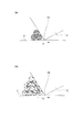
図8は、クリーニングブレードのエッジ部12E(接触領域)付近の様子を模式的に示した図である。
<< Developer cartridge usage and toner purge timing >>
FIG. 8 is a diagram schematically showing a state near the
現像カートリッジ3の使用開始時は、トナー70には多くの外添剤30bが付着している。このため、図8(a)に示される通り、少量のトナー70をクリーニングブレードのエッジ部12E(接触領域)に送り込んでも、エッジ部12Eに十分な外添剤30bが送り込まれる。
At the start of use of the developing cartridge 3, many
しかし、現像カートリッジ3が使用され続ける(現像カートリッジの使用量が大きくなる)と、トナー70は現像ブレード32や供給ローラ33などとの摺擦を繰り返すことによって「劣化」する。ここで言う「劣化」とは、外添剤30bが樹脂粒子30aから剥れたり、樹脂粒子内に埋め込まれたりしてしまうことである。トナー70の劣化が進むと、クリーニングブレード12への外添剤30bの移行量が少なくなって、その潤滑性は低下し、両者の摩擦低減効果が持続しにくくなる。そこで、トナー劣化が進む耐久後半(使用後半)は、1回のトナー供給(パージ)工程におけるトナー量を増やすか、トナー供給(パージ)工程の実施頻度を上げるなどする必要がある。トナー量を増やす場合は、図8(b)に示すように、多くのトナー70がクリーニングブレードのエッジ部12Eに送り込まれ、トナー70を矢印Xの方向に移動しながら滞留させて潤滑性を確保している。以上のことから、現像カートリッジ3内のトナー劣化の進行度が分かれば、トナー供給(パージ)工程でどの程度の量のトナー70をクリーニングブレード12へ送ればよいかが判断できる。
However, as the developing cartridge 3 continues to be used (the usage amount of the developing cartridge increases), the
本実施例においては、トナー劣化の進行度を表す指標として、現像ローラ31の回転数を用いた。これは、トナー70の劣化が、主に現像ローラ31及び現像ブレード32間の摺擦により進行するためである。現像ローラ31の回転速度は一定であるので、現像駆動モータの駆動時間を積算することで、現像ローラ31の回転数を検知することができる。現像ローラ31の回転数は、現像ローラ31の駆動動作を検知し、使用開始からリセットされることなく積算していく。現像ローラ31の使用量は、使用開始時を0%として、カブリ、縦スジ等の画像不良が発生する恐れのある現像ローラ31の回転数を100%として、以下の通り制御部103によって算出される。
現像ローラの使用量(%)=現像ローラの積算回転数/画像不良発生の恐れのある現像ローラの総回転数×100 ・・・式(1)
In this embodiment, the rotation speed of the developing
Development roller usage (%) = Total number of rotations of development roller / Total number of rotations of development roller that may cause image defect × 100 (1)
そして、算出された現像ローラ31の使用量は、制御部103により記憶素子37に書き込まれる。また、必要に応じて、画像形成装置の装置本体100(制御部103)は、記憶素子37から現像ローラ31の使用量を参照することができる。
現像ローラの使用量(%)=現像ローラのこれまでの駆動時間/画像不良発生の恐れのある現像ローラの総駆動時間×100 ・・・式(2)
The calculated usage amount of the developing
Development roller usage (%) = development roller drive time so far / development roller total drive time that may cause image failure × 100 (2)
《クリーニングカートリッジの使用状況とトナー供給のタイミング》
クリーニングカートリッジ1の使用開始時には、クリーニングブレードのエッジ部12Eと感光ドラム10表面とにはトナー70が全く存在しない。このため、クリーニングブレード12と感光ドラム10との潤滑性が低く摩擦力は大きい。それゆえ、トナー供給(パージ)工程によって所定量の外添剤30bを移行させ、潤滑性を確保する。このとき、移行させるトナー70の供給量は、前述の通り、トナー70の劣化の程度によって決まる。
《Cleaning cartridge usage and toner supply timing》
At the start of use of the cleaning cartridge 1, the
現像カートリッジ3が使用初期に近い(現像ローラ31の回転数が少ない)状態であれば、トナーに付着した外添剤30bの量は多い。このため、図8(a)に示されるように少量のトナー70を送るだけでクリーニングブレードのエッジ部12Eに外添剤30bが送り込まれ、潤滑性は確保される。また、本実施例では、クリーニングカートリッジ1と現像カートリッジ3とが独立に着脱可能である。このため、使用初期のクリーニングカートリッジ1に対し、トナー劣化が進んだ使用後半の現像カートリッジ3(現像ローラ31の回転数が多い)が組み合わされる可能性もありうる。この場合は、トナーに付着した外添剤30bの量が減っているため、図8(b)に示されるように、ある程度多くのトナー70をクリーニングブレードのエッジ部12Eに送り込む必要がある。これは、図8(b)に示すように、これらのトナー70をクリーニングブレードのエッジ部12E付近に矢印Xの方向に対流させ潤滑性を確保するためである。
If the developing cartridge 3 is close to the initial use (the rotation speed of the developing
現像カートリッジの使用が進み、クリーニングカートリッジ1に対して使用されている1本目の現像カートリッジ3が寿命を迎え、2本目の現像カートリッジに交換される場合がある。2本目の現像カートリッジに交換されたときは、図9に示されるような状態になる。クリーニングブレードのエッジ部12E付近には、1本目の現像カートリッジ3使用時にトナー供給(パージ)工程で供給されたトナー70がクリーニングブレードのエッジ部12Eに滞留している。その他に、転写残やカブリなどの残トナー70cがクリーニングブレードのエッジ部12Eに溜まって矢印Y方向に対流している。この場合は、これらが潤滑性を保つ役割を果たすため、残トナー70cが溜まっているクリーニングカートリッジ1に対しては、トナー供給(パージ)工程でのトナー使用量を減らしたとしても潤滑性低下に起因した課題が発生することはない。
As the use of the developing cartridge progresses, the first developing cartridge 3 used for the cleaning cartridge 1 may reach the end of its life and be replaced with the second developing cartridge. When the cartridge is replaced with the second developing cartridge, the state is as shown in FIG. In the vicinity of the
本実施例において、残トナー70cの量の算出には、露光装置2の発光する画素(ピクセル)数をカウントすることの出来る計測手段(ピクセルカウント)を用いる。制御部103により構成されても良いし、制御部103とは別途で設けるようしても良い。ピクセルカウントとは、形成される画像の画像ドットを形成する個々の画像信号をカウントすることである。ある画像を現像するために要するトナー量は、制御部103により露光部材2が発光するピクセル数からトナー使用量を推定される。クリーニングブレードに回り込む廃トナー量は、実際に使用されたトナー量にある割合を乗じた値となる。また、ジャム等のミスプリント時や、トナー供給(パージ)工程などにおける廃トナーに関しては、消費されたトナーが記録シート上に画像として外部出力されない。つまりピクセルカウントされた画素が全て廃トナーとなるので、制御部103は、実際にドットをカウントしたピクセルカウントを廃トナー量として加算する。
In the present embodiment, for the calculation of the amount of the remaining toner 70c, a measuring unit (pixel count) that can count the number of pixels (pixels) emitted by the
なお、廃トナー収容割合は、以下のように算出する。
廃トナー収容割合(%)=ピクセルカウントで算出された廃トナー量/クリーニング枠体に収容可能な廃トナー量×100 ・・・式(3)
The waste toner storage ratio is calculated as follows.
Waste toner storage ratio (%) = waste toner amount calculated by pixel count / waste toner amount that can be stored in the cleaning frame × 100 (3)
制御部103は、1本のクリーニングカートリッジ1に対し複数の現像カートリッジ3が使用される状況下において、クリーニング部材で回収された現像剤に係る値として、複数の現像カートリッジ3を通してのトータル廃トナー量を記録する。つまり、制御部103は、クリーニング部材で回収された現像剤に係る値を、複数の現像カートリッジ3を通して記憶素子13に記憶し、演算に用いる。
In a situation where a plurality of developing cartridges 3 are used for one cleaning cartridge 1, the
本明細書では、クリーニング部材で回収された現像剤量は、直接的に検出した現像剤量だけでなく、上述した廃トナー収容割合や廃トナー量をも含めるものである。 In this specification, the amount of developer collected by the cleaning member includes not only the amount of developer directly detected but also the above-described waste toner storage ratio and waste toner amount.
以上に説明した通り、本実施例のように1本のクリーニングカートリッジ1に対し、2本以上の未使用の現像カートリッジ3が使用される構成に対しては、2本目以降で最初のトナー供給量を少なくできる。 As described above, for the configuration in which two or more unused developing cartridges 3 are used for one cleaning cartridge 1 as in the present embodiment, the first and subsequent toner supply amounts are used. Can be reduced.
最初のトナー供給量とは、未使用の現像カートリッジからトナーを供給するトナー供給(パージ)工程を行う際に、現像カートリッジからドラムを介してクリーニング部材に供給されるトナーの量のことである。 The initial toner supply amount is the amount of toner supplied from the developing cartridge to the cleaning member via the drum when performing a toner supplying (purging) process for supplying toner from an unused developing cartridge.
つまり、未使用1本目の現像カートリッジ3が最初のトナー供給(パージ)工程で使用するトナー量よりも、2本目以降の現像カートリッジ3が最初のトナー供給(パージ)工程で使用するトナー量を少なくすることが可能となる。 In other words, the amount of toner used by the second and subsequent developing cartridges 3 in the first toner supply (purge) step is smaller than the amount of toner used by the unused first developing cartridge 3 in the first toner supply (purge) step. It becomes possible to do.
また、クリーニングカートリッジの印字可能枚数は、現像カートリッジの印字可能枚数よりも多い構成に対しては、2本目以降で最初のトナー供給量を少なくできる。 In addition, the first toner supply amount can be reduced after the second cartridge for the configuration in which the number of printable sheets of the cleaning cartridge is larger than the number of printable sheets of the developing cartridge.
<トナー供給(パージ)工程での供給量(パージ量)の決定>
本発明の実施形態1に係る、画像形成装置においてトナー供給(パージ)工程を行った際の動作シーケンスについて説明する。
<Determination of Supply Amount (Purge Amount) in Toner Supply (Purge) Process>
An operation sequence when the toner supply (purge) step is performed in the image forming apparatus according to the first embodiment of the present invention will be described.
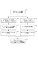
図10はトナー供給(パージ)工程を行う際のフローチャートである。クリーニングカートリッジ1、現像カートリッジ3が画像形成装置に装着され、画像形成装置の電源が投入される。そして、画像形成装置の制御部103でクリーニングカートリッジ1と現像カートリッジ3が装置本体に装着されていることを検出する。本実施例では制御部103は装着の有無を検出する検出部でもある(S1)。
FIG. 10 is a flowchart when the toner supply (purge) step is performed. The cleaning cartridge 1 and the developing cartridge 3 are mounted on the image forming apparatus, and the image forming apparatus is turned on. Then, the
画像形成装置の電源が投入された後、クリーニングカートリッジ1に搭載された第1記憶素子13と装置本体内の通信手段との通信を介して、プロセスカートリッジ枠体67内の廃トナー収容割合(%)が制御部103により読み取られる(S2)。
After the power of the image forming apparatus is turned on, the waste toner containing ratio (%) in the
次に、制御部103で、クリーニングブレードのエッジ12E部分にどの程度のトナーが存在するかを推定する。これは、外添剤の量を推定するものでもよい(S3)。制御部103は、推定された値(情報)を、トナーパージ条件決定テーブルへエントリーさせる(S4)。
Next, the
並行して、制御部103は、現像カートリッジ3に搭載された記憶素子37と装置本体内の通信手段との通信によって、現像ローラ使用量を読み取る(S5)。その後、制御部103は、現像カートリッジ3内のトナー劣化の進行度を推定する(S6)。そして、制御部103は、トナーパージ条件決定テーブルへ情報をエントリーする(S7)。
In parallel, the
制御部103は、S4とS7とでクリーニングカートリッジ1側と現像カートリッジ3側とからエントリーされた情報を元に、トナー供給(パージ)条件(トナー供給量)を決定する(S8)。尚、ここでのエントリーとは、記憶素子から読まれた情報を、トナーパージ条件決定テーブルから特定のトナー供給(パージ)条件を特定する為のパラメーターとして用いる処理を指すものとする。
The
本発明者は、トナーパージ条件決定テーブルを作成するために、次のような実験を行った。 The inventor conducted the following experiment in order to create the toner purge condition determination table.
本発明者らは、クリーニングカートリッジ1と現像カートリッジ3とが独立に着脱可能な装置本体を用い、クリーニングカートリッジ1内の廃トナー量を変えて、現像カートリッジの耐久テストを行った。所定枚数ごとにトナー供給(パージ)工程を1回入れたとき、耐久終了までクリーニングブレードのビビり(振動)に起因した異音が発生しない最小トナー供給(パージ)量を調べた。 The inventors conducted an endurance test of the developing cartridge by using an apparatus main body in which the cleaning cartridge 1 and the developing cartridge 3 can be independently attached and detached, and changing the amount of waste toner in the cleaning cartridge 1. When the toner supply (purge) process was performed once for every predetermined number of sheets, the minimum toner supply (purge) amount at which no abnormal noise due to chatter (vibration) of the cleaning blade occurred until the end of the durability was examined.
〔条件〕
・温度10℃湿度10%での2枚間欠耐久 印字率0.3%で5000枚まで
・廃トナー収容割合 0、20、40、60、80% で5回耐久を実施
・トナー供給(パージ)工程を印字100枚毎に1回実施
・プロセススピード:100mm/sec
〔conditions〕
・ Two-sheet intermittent durability at a temperature of 10 ° C and humidity of 10% Up to 5000 sheets with a printing rate of 0.3% ・ Waste toner storage ratio: 0, 20, 40, 60, 80% The process is performed once every 100 prints. Process speed: 100mm / sec

表1は、上述の条件で1回のトナー供給(パージ)工程で消費されるトナー量(mg)を示すものである。この条件であれば、異音が発生しない。よって、表1に示されるものをそのままトナーパージ条件決定テーブルとして用いてもよい。つまり、表1は、トナーパージ条件決定テーブルの一例である。 Table 1 shows the toner amount (mg) consumed in one toner supply (purge) step under the above-described conditions. Under this condition, no abnormal noise is generated. Therefore, the table shown in Table 1 may be used as it is as the toner purge condition determination table. That is, Table 1 is an example of a toner purge condition determination table.
また、表1からも分かるように、現像カートリッジの使用量が同じ場合に、クリーニング部材で回収された現像剤量が多いと、トナー供給量が少なくなる。クリーニング部材で回収された現像剤量が同じ場合に、現像カートリッジの使用量が多いと、供給量が多くなる。 Further, as can be seen from Table 1, when the usage amount of the developing cartridge is the same, if the developer amount collected by the cleaning member is large, the toner supply amount is reduced. When the developer amount collected by the cleaning member is the same, the supply amount increases if the amount of the developer cartridge used is large.
表1の実験結果によれば、仮に1本のクリーニングカートリッジで5本の現像カートリッジを使用可能な画像形成装置を考えた場合、現像カートリッジの使用本数が増えるにつれて、トナー供給(パージ)工程で消費されるトナー量を減らせることが分かる。 According to the experimental results in Table 1, if an image forming apparatus capable of using five developing cartridges with one cleaning cartridge is considered, as the number of used developing cartridges increases, it is consumed in the toner supply (purge) process. It can be seen that the amount of toner used can be reduced.
なお、本実験においては、トナー供給(パージ)工程を所定枚数で入れて、1回のトナー供給(パージ)工程におけるトナー供給(パージ)量を変化させる方法で検証を行った。しかし、これに限定されず、単位枚数当たりのトナー供給(パージ)量を廃トナー収容割合が多いほど少なくできれば同様の効果を期待できる。 In this experiment, verification was performed by a method in which a predetermined number of toner supply (purge) steps were inserted and the amount of toner supply (purge) in one toner supply (purge) step was changed. However, the present invention is not limited to this, and the same effect can be expected if the toner supply (purge) amount per unit number can be reduced as the waste toner accommodation ratio increases.
制御部103は、クリーニング部材で回収された現像剤量に対応する信号と現像カートリッジの使用量に対応する信号とを、画像形成装置の内部に格納されている参照テーブルと比較し、トナー供給量を決定している。上述のトナーパージ条件決定テーブルは、参照テーブルの一例である。
The
尚、表1のトナーパージ条件決定テーブルでは、縦軸に式(1)、(2)などで定義される現像ローラのトナー使用量が用いられているが、実施例はこれに限定されない。現像ローラ(現像カートリッジ)の使用量に係る値であれば適宜用いることができる。例えば、使用量を現像ローラの回転数、時間そのものとしても良い。またトナーパージ条件決定テーブルは、現像ローラの使用量ではなく、現像ローラの残り駆動量を縦軸に持っても良い。現像ローラの残り駆動量(残り寿命)も現像ローラ(現像カートリッジ)の何れも使用量に係る値といえる。この場合、画像不良発生の恐れのある現像ローラの総回転数から現像ローラの積算回転数を減じた値や、それらの比に100を乗じた%値が、現像ローラ(現像カートリッジ)の残り駆動量に相当する。 In the toner purge condition determination table of Table 1, the toner usage amount of the developing roller defined by the equations (1) and (2) is used on the vertical axis, but the embodiment is not limited to this. Any value relating to the amount of use of the developing roller (developing cartridge) can be used as appropriate. For example, the amount used may be the number of rotations of the developing roller and the time itself. Further, the toner purge condition determination table may have the remaining driving amount of the developing roller on the vertical axis instead of the usage amount of the developing roller. Both the remaining driving amount (remaining life) of the developing roller and the developing roller (developing cartridge) can be said to be values related to the usage amount. In this case, a value obtained by subtracting the total number of rotations of the developing roller from the total number of rotations of the developing roller that may cause image defects, or a value obtained by multiplying the ratio by 100 is the remaining drive of the developing roller (developing cartridge). It corresponds to the amount.
また、表1のトナーパージ条件決定テーブルの横軸についても、廃トナー収容割合に限定されない。廃トナーとして回収された現像剤量に係る値であれば適宜用いることができる。例えば廃トナー量でも良いし、残り廃トナー収容量、或いは残りは廃トナー収容割合でも良い。残り廃トナー収容量、及び残り廃トナー収容割合の何れも廃トナーとしてクリーニング部材で回収された現像剤量に係る値に相当させることができる。 Further, the horizontal axis of the toner purge condition determination table in Table 1 is not limited to the waste toner accommodation ratio. Any value relating to the amount of developer collected as waste toner can be used as appropriate. For example, the amount of waste toner may be used, the remaining amount of waste toner stored, or the remaining amount may be the waste toner storage rate. Both the remaining waste toner storage amount and the remaining waste toner storage ratio can correspond to values related to the developer amount recovered by the cleaning member as waste toner.
また、廃トナー量について、上の説明ではピクセルカウントに基づく量として説明したが、これに限定されない。廃トナー量を、既に周知の機械的、光学的センサーにより検出し、その出力値を制御部103が読み取り推定して良い。即ち、このように検出されたセンサー値も、クリーニング部材で回収された現像剤量に係る値に相当させることができる。
In addition, the amount of waste toner has been described as an amount based on the pixel count in the above description, but is not limited thereto. The amount of waste toner may be detected by a known mechanical or optical sensor, and the output value may be read and estimated by the
更に、表1のトナーパージ条件決定テーブルでは、横軸に、廃トナー収容割合を持っているが、これに限定されない。廃トナー量に係る値であれば、他の量を採用しても良い。例えば、クリーニングブレードに回り込む廃トナー量と、実際に使用されたトナー量との間に、マクロ的に一定の相関関係があるのであれば、1つのクリーニングカートリッジに対して装着され可動した複数の現像カートリッジのトータル使用量を採用しても良い。このような値も、クリーニング部材で回収された現像剤量に係る値に相当させることができる。上記の変形例は後述の各実施例でも同様である。 Furthermore, in the toner purge condition determination table of Table 1, the horizontal axis has the waste toner accommodation ratio, but the present invention is not limited to this. Other values may be adopted as long as the values are related to the amount of waste toner. For example, if there is a certain macroscopic correlation between the amount of waste toner that wraps around the cleaning blade and the amount of toner that is actually used, a plurality of developments that are mounted and moved with respect to one cleaning cartridge You may employ | adopt the total usage-amount of a cartridge. Such a value can also correspond to a value related to the developer amount collected by the cleaning member. The above-described modifications are the same in the embodiments described later.
本発明の第2の実施例について、図11を用いて説明する。 A second embodiment of the present invention will be described with reference to FIG.
なお、本実施例においては、実施例1に対して異なる構成部分について述べることとし、実施例1と同様の構成部分については、その説明を省略する。 In the present embodiment, the different components from the first embodiment will be described, and the description of the same components as those in the first embodiment will be omitted.
本実施例の特徴は、感光ドラム、帯電装置、現像装置、クリーニング装置を備えるプロセスカートリッジと、トナーを含有するトナーカートリッジを各々独立に着脱可能にしたところである。このような形態に対しても、本発明は適用可能である。 A feature of this embodiment is that a process cartridge including a photosensitive drum, a charging device, a developing device, and a cleaning device and a toner cartridge containing toner can be independently attached and detached. The present invention can also be applied to such a form.
画像形成装置は、装置本体100内に少なくともプロセスカートリッジ6、露光装置2、トナーカートリッジ7、転写装置4、定着装置5を備えている。本実施例においては、プロセスカートリッジ6、および、トナーカートリッジ7は、各々が独立に装置本体100から着脱可能となっている。
The image forming apparatus includes at least a
プロセスカートリッジ6は、像担持体たる感光ドラム60、帯電部材たる帯電ローラ61、クリーニング部材たるクリーニングブレード62を有する。さらに、プロセスカートリッジは、現像ローラ63、現像ブレード64、供給ローラ65、画像形成装置と通信可能な記憶素子66をプロセスカートリッジ枠体67に有する。トナーカートリッジ7は、少なくとも、トナー70、画像形成装置と通信可能な記憶素子71をトナーカートリッジ枠体72に有している。
The
このようにプロセスカートリッジ6とトナーカートリッジ7とを独立に着脱可能にしているのは、各々のカートリッジを寿命まで効率的に使用するためである。そのため、1本のプロセスカートリッジ6に対し、3本〜7本程度のトナーカートリッジ7が使用される構成が一般的である。
The reason why the
<非画像形成時のトナー供給(パージ)工程>
本実施例においても、トナー供給(パージ)工程をどのタイミングで入れるかは、トナーカートリッジ7やプロセスカートリッジ6の使用状況によって決めることができる。
<Toner supply (purge) process during non-image formation>
Also in this embodiment, it is possible to determine at what timing the toner supply (purge) step is performed according to the usage status of the
《トナーカートリッジの使用状況とトナー供給条件》
実施例1で説明したように、トナー劣化の進行度が分かれば、トナー供給(パージ)工程での必要なトナー供給量が分かる。実施例1においては、トナー劣化の進行度を現像ローラの回転数で検出したが、この方法以外にもトナー劣化の進行度は現像装置内のトナー70の残量によっても検出可能である。図11において、トナー70の残量が多いときは、供給ローラ65から現像ローラ63には、劣化が進行していないフレッシュなトナー70が多く供給される。現像ローラの使用が進み、トナー70の残量が減ってくると、現像ローラ63上には現像ブレード64などとの摺擦を受けた履歴を有するトナー70が存在する確率が高くなる。トナー70は、現像ブレード64などとの摺擦頻度はトナー劣化の進行度と相関する。したがって、トナー70の残量を検出することによっても、トナー劣化の進行度を検出できる。
<Toner cartridge usage and toner supply conditions>
As described in the first exemplary embodiment, if the degree of progress of toner deterioration is known, the necessary toner supply amount in the toner supply (purge) step can be known. In the first embodiment, the degree of progress of toner deterioration is detected by the number of rotations of the developing roller. However, in addition to this method, the degree of progress of toner deterioration can also be detected by the remaining amount of
本実施例においては、トナーカートリッジ7にとりつけられた第3記憶素子71にトナー残量を記憶し、トナー残量で劣化の進行度を判定した。トナー残量の初期値は、初期(未使用時)のトナーカートリッジ内のトナー充填量(トナー量)を初期値とした。この初期値は、第3記憶素子71に記憶させておき、そこから画像信号に基づくピクセルカウントの値に応じたトナー量を算出し、初期値から減算していく方式をとった。本実施例では、トナーカートリッジ7のトナー残量とトナーカートリッジの使用量は同じものである。
In this embodiment, the remaining amount of toner is stored in the
《クリーニングカートリッジの使用状況とトナー供給条件》
プロセスカートリッジ6内の廃トナー量が分かれば、トナー供給(パージ)工程で、どの程度の量のトナー70をクリーニングブレード12へ送ればよいかが判断できる。本実施例においても、廃トナー量はピクセルカウントから算出する方式をとった。
《Cleaning cartridge usage and toner supply conditions》
If the amount of waste toner in the
<トナー供給(パージ)工程でのパージ量の決定>
本発明の実施形態2に係る、画像形成装置においてトナー供給(パージ)工程を行った際の動作シーケンスについて説明する。
<Determination of purge amount in toner supply (purge) process>
An operation sequence when a toner supply (purge) step is performed in the image forming apparatus according to the second embodiment of the present invention will be described.
図12はトナー供給(パージ)工程を行う際のフローチャートである。 FIG. 12 is a flowchart when the toner supply (purge) step is performed.
プロセスカートリッジ6、トナーカートリッジ7が画像形成装置に装着され、制御部103により装着したか検出され、同じく制御部103により装着が確認できた場合に次の工程に進む(S11)。
When the
プロセスカートリッジ6に搭載された第1記憶素子66と装置本体内の通信手段との通信を介して、クリーニング枠体内の廃トナー収容割合(%)が制御部103により読み取られる(S12)。
The waste toner storage ratio (%) in the cleaning frame is read by the
制御部103は、1本のプロセスカートリッジ6に対し複数のトナーカートリッジ7が使用される状況下において、クリーニング部材で回収された現像剤に係る値として、複数のトナーカートリッジ7を通してのトータル廃トナー量を記録する。つまり、制御部103は、クリーニング部材で回収された現像剤に係る値を、複数の現像カートリッジ7を通して記憶素子66に記憶し、演算に用いる。
In a situation where a plurality of
読み取った情報をもとに、制御部は103、クリーニングブレードのエッジ12E部分にどの程度のトナーが存在するかを推定する(S13)。そして、制御部103は、推定した値(情報)をトナーパージ条件決定テーブルへ情報をエントリーする(S14)。
Based on the read information, the
並行して、制御部103は、トナーカートリッジ7に搭載された第3記憶素子71と装置本体内の通信手段との通信によって、トナー残量或いは使用量を読み取る(S15)。廃トナー収容割合の求め方については実施例1で説明した通りであるが、トナーカートリッジ内の使用量(%)については、制御部103が、ピクセルカウント値に基づき算出しても良いし、既に周知の光学式センサー出力値を取得するようにしても良い。その後、制御部103は、トナーカートリッジ7内のトナー劣化の進行度を推定する(S16)。そして、制御部は、トナーパージ条件決定テーブルへ情報をエントリーする(S17)。S14とS17でプロセスカートリッジ6側とトナーカートリッジ7側からエントリーされた情報を元に、トナー供給条件を決定する(S18)。
In parallel, the
実施形態2においても、上記フローチャートよりトナー供給(パージ)工程で消費されるトナー量が決定されるため、実施形態1と同様の効果が望める。 Also in the second embodiment, since the amount of toner consumed in the toner supply (purge) step is determined from the above flowchart, the same effect as in the first embodiment can be expected.
(その他)
カートリッジは、現像剤を収容するトナーカートリッジ、少なくとも現像剤担持体を有する現像カートリッジ、さらに、少なくともクリーニング部材を有すクリーニングカートリッジがある。さらに、少なくとも像担持体とそれに作用するプロセス手段とを有するプロセスカートリッジなどがある。
(Other)
As the cartridge, there are a toner cartridge for containing a developer, a developing cartridge having at least a developer carrying member, and a cleaning cartridge having at least a cleaning member. Further, there is a process cartridge having at least an image carrier and process means acting on the image carrier.
ここで、現像カートリッジは、現像カートリッジ自体が現像剤を収容する枠体を有し、収容された現像剤を使い切ったら、現像カートリッジ自体を交換するような形態がある。また、現像カートリッジには、現像剤を収容するトナーカートリッジを現像カートリッジとは別に着脱可能に持つような構成でもよい。この場合、現像カートリッジは、現像剤担持体を支持する枠体の現像剤を収容できる空間に現像剤をトナーカートリッジから補給できる構成になる。 Here, the developing cartridge has a frame in which the developing cartridge itself stores the developer, and the developing cartridge itself is replaced when the stored developer is used up. Further, the developing cartridge may have a configuration in which a toner cartridge for storing the developer is detachable from the developing cartridge. In this case, the developing cartridge is configured such that the developer can be replenished from the toner cartridge into a space that can store the developer of the frame that supports the developer carrying member.
クリーニングカートリッジは、像担持体と像担持体をクリーニングするクリーニング部材を有する。多くの場合は、クリーニングカートリッジを装置本体に装着すると、現像カートリッジも装置本体に装着する必要がある。実施例1がこの形態である。 The cleaning cartridge includes an image carrier and a cleaning member that cleans the image carrier. In many cases, when the cleaning cartridge is attached to the apparatus main body, it is necessary to attach the developing cartridge to the apparatus main body. Example 1 is this form.
プロセスカートリッジは、少なくとも像担持体を有していればよい。多くの場合、像担持体を帯電する帯電手段、像担持体上の静電像を現像する現像手段を有する構成をいう。さらに、プロセスカートリッジにトナーを補給するためのトナーカートリッジが着脱可能な構成でもよい。実施例2がこの形態である。 The process cartridge may have at least an image carrier. In many cases, this means a structure having a charging means for charging the image carrier and a developing means for developing an electrostatic image on the image carrier. Furthermore, a configuration in which a toner cartridge for supplying toner to the process cartridge is detachable may be used. Example 2 is this form.
画像形成装置の装置本体には、プロセスカートリッジが着脱可能に装着される構成でも、現像カートリッジとクリーニングカートリッジが着脱可能な構成でもよい。さらに、2体の場合は、クリーニングカートリッジに現像カートリッジを取り付けた後に画像形成装置の装置本体に装着する形態や、それぞれが他のカートリッジの装着状態に関係なく装置本体に装着することができる構成でもよい。 The apparatus main body of the image forming apparatus may be configured such that the process cartridge is detachably mounted, or may be configured such that the developing cartridge and the cleaning cartridge are detachable. Further, in the case of two units, a configuration in which the developing cartridge is attached to the cleaning cartridge and then attached to the main body of the image forming apparatus, or each of them can be attached to the main body of the apparatus regardless of the mounting state of other cartridges Good.
上記各実施例によれば、クリーニング部材に送り込む現像剤の量を低減できる画像形成装置を提供することである。 According to each of the above embodiments, it is an object to provide an image forming apparatus capable of reducing the amount of developer fed to the cleaning member.
Claims (12)
現像剤を前記像担持体に搬送する現像剤担持体を有する現像カートリッジと、を有し、前記クリーニングカートリッジと前記現像カートリッジとは画像形成装置の装置本体に対して、それぞれ着脱可能な画像形成装置であって、
非画像形成時に前記現像カートリッジから前記像担持体を介して前記クリーニング部材に前記現像剤が供給される現像剤の供給工程を実行する制御部を有し、
前記制御部は、前記現像剤の供給工程で前記現像カートリッジから前記クリーニング部材に供給される前記現像剤の供給量を、前記クリーニング部材で回収された現像剤量に係る値と前記現像カートリッジの使用量に係る値とに基づいて、決定することを特徴とする画像形成装置。 A cleaning cartridge comprising: an image carrier; and a cleaning member that contacts the image carrier and cleans the image carrier;
A developer cartridge having a developer carrier for conveying the developer to the image carrier, and the cleaning cartridge and the developer cartridge are detachable from the apparatus main body of the image forming apparatus, respectively. Because
A control unit that executes a developer supplying step in which the developer is supplied from the developer cartridge to the cleaning member via the image carrier during non-image formation;
The control unit supplies the amount of the developer supplied from the developing cartridge to the cleaning member in the developer supplying step, the value relating to the amount of developer collected by the cleaning member, and the use of the developing cartridge. An image forming apparatus characterized in that it is determined based on a value relating to a quantity.
前記制御部は、前記現像剤の供給量を、複数の現像カートリッジに関して前記クリーニング部材で回収された現像剤量に係る値と前記現像カートリッジの使用量に係る値とに基づいて、決定することを特徴とする請求項1に記載の画像形成装置。 It is possible to use two or more unused developing cartridges for one cleaning cartridge,
The control unit determines the supply amount of the developer based on a value related to the developer amount collected by the cleaning member and a value related to the usage amount of the developer cartridge with respect to a plurality of developer cartridges. The image forming apparatus according to claim 1, wherein:
前記クリーニングカートリッジが1本に対し、未使用の現像カートリッジの1本目を前記装置本体に装着した後の前記現像剤の供給工程における最初の前記供給量は、2本目以降の未使用の現像カートリッジを前記装置本体に装着した後の前記現像剤の供給工程における最初の前記供給量より、少ないことを特徴とする請求項1から5のいずれか1項に記載の画像形成装置。 It is possible to use two or more unused developing cartridges for one cleaning cartridge,
With respect to one cleaning cartridge, the first supply amount in the developer supplying process after the first unused developing cartridge is mounted on the apparatus main body is the same as the second and subsequent unused developing cartridges. 6. The image forming apparatus according to claim 1, wherein the image forming apparatus is smaller than an initial supply amount in the developer supply step after being mounted on the apparatus main body.
前記現像剤担持体に現像剤を供給するためのトナーカートリッジと、を有し、画像形成装置の装置本体に対して前記プロセスカートリッジが着脱可能な画像形成装置であって、
非画像形成時に前記現像剤担持体から前記像担持体を介して前記クリーニング部材に前記現像剤が供給される現像剤の供給工程を実行する制御部を有し、
前記制御部は、前記現像剤の供給工程で前記現像剤担持体から前記クリーニング部材に供給される前記現像剤の供給量を、前記クリーニング部材で回収された現像剤量に係る値と前記トナーカートリッジの使用量に係る値とに基づいて決定することを特徴とする画像形成装置。 A process cartridge comprising: an image carrier; a cleaning member that contacts the image carrier to clean the image carrier; and a developer carrier that transports the developer to the image carrier;
A toner cartridge for supplying a developer to the developer carrying member, wherein the process cartridge is attachable to and detachable from an apparatus main body of the image forming apparatus,
A controller that performs a developer supplying step in which the developer is supplied from the developer carrier to the cleaning member via the image carrier during non-image formation;
The controller includes a developer supply amount supplied from the developer carrier to the cleaning member in the developer supply step, a value related to the developer amount collected by the cleaning member, and the toner cartridge. And an image forming apparatus that determines the amount based on a value related to the amount of use.
前記制御部は、前記現像剤の供給量を、複数のトナーカートリッジに関して前記クリーニング部材で回収された現像剤量に係る値と前記トナーカートリッジの使用量に係る値とに基づいて、決定することを特徴とする請求項7に記載の画像形成装置。 It is possible to use two or more unused toner cartridges for one process cartridge,
The control unit determines the supply amount of the developer based on a value related to the developer amount collected by the cleaning member and a value related to the usage amount of the toner cartridge for a plurality of toner cartridges. The image forming apparatus according to claim 7.
前記プロセスカートリッジが1本に対し、未使用のトナーカートリッジの1本目を前記装置本体に装着した後の前記現像剤の供給工程における最初の前記供給量は、2本目以降の未使用のトナーカートリッジを前記装置本体に装着した後の前記現像剤の供給工程における最初の前記供給量より、少ないことを特徴とする請求項7から11のいずれか1項に記載の画像形成装置。
It is possible to use two or more unused toner cartridges for one process cartridge,
The first supply amount in the developer supplying process after the first unused toner cartridge is mounted on the apparatus main body with respect to one process cartridge is the second and subsequent unused toner cartridges. 12. The image forming apparatus according to claim 7, wherein the image forming apparatus is less than an initial supply amount in the developer supply process after being mounted on the apparatus main body.
Applications Claiming Priority (2)
| Application Number | Priority Date | Filing Date | Title |
|---|---|---|---|
| JP2017031353 | 2017-02-22 | ||
| JP2017031353 | 2017-02-22 |
Publications (2)
| Publication Number | Publication Date |
|---|---|
| JP2018136533A true JP2018136533A (en) | 2018-08-30 |
| JP2018136533A5 JP2018136533A5 (en) | 2021-03-25 |
Family
ID=61249542
Family Applications (1)
| Application Number | Title | Priority Date | Filing Date |
|---|---|---|---|
| JP2018019619A Pending JP2018136533A (en) | 2017-02-22 | 2018-02-06 | Image forming device |
Country Status (3)
| Country | Link |
|---|---|
| US (1) | US10338495B2 (en) |
| EP (1) | EP3367178B1 (en) |
| JP (1) | JP2018136533A (en) |
Cited By (1)
| Publication number | Priority date | Publication date | Assignee | Title |
|---|---|---|---|---|
| JP7446787B2 (en) | 2019-11-19 | 2024-03-11 | キヤノン株式会社 | image forming device |
Families Citing this family (3)
| Publication number | Priority date | Publication date | Assignee | Title |
|---|---|---|---|---|
| JP7098339B2 (en) * | 2018-01-24 | 2022-07-11 | キヤノン株式会社 | Image forming device |
| JP7205331B2 (en) * | 2019-03-20 | 2023-01-17 | 株式会社リコー | Image forming apparatus, image forming method, and program |
| US11675558B1 (en) * | 2022-03-18 | 2023-06-13 | Toshiba Tec Kabushiki Kaisha | Image forming apparatus and method which performs printing according to an electrophotographic scheme |
Citations (5)
| Publication number | Priority date | Publication date | Assignee | Title |
|---|---|---|---|---|
| JP2006011404A (en) * | 2004-05-25 | 2006-01-12 | Canon Inc | Image forming apparatus and its control method |
| US20070003324A1 (en) * | 2005-06-30 | 2007-01-04 | Xerox Corporation | Method and system for improved implementation of maintenance routines in a productive system |
| JP2010122468A (en) * | 2008-11-19 | 2010-06-03 | Canon Inc | Image forming apparatus |
| JP2011150311A (en) * | 2009-12-21 | 2011-08-04 | Canon Inc | Image forming apparatus |
| JP2014119662A (en) * | 2012-12-18 | 2014-06-30 | Canon Inc | Image forming apparatus |
Family Cites Families (9)
| Publication number | Priority date | Publication date | Assignee | Title |
|---|---|---|---|---|
| JP3313978B2 (en) | 1996-07-26 | 2002-08-12 | キヤノン株式会社 | Process cartridge and electrophotographic image forming apparatus |
| JP3890266B2 (en) * | 2002-07-03 | 2007-03-07 | キヤノン株式会社 | Block polymer compound, ink composition, dispersible composition, image forming method, and image forming apparatus |
| JP2004354933A (en) * | 2003-05-30 | 2004-12-16 | Oki Data Corp | Image forming apparatus |
| US7819790B2 (en) * | 2004-02-20 | 2010-10-26 | Dixie Consumer Products Llc | Apparatus for making paperboard pressware with controlled blank feed |
| US20070201897A1 (en) * | 2005-07-15 | 2007-08-30 | Seiko Epson Corporation | Image forming apparatus and image forming method |
| US7877054B1 (en) * | 2009-07-14 | 2011-01-25 | Xerox Corporation | Process for development of cleaning blade lubrication stripes |
| JP5316289B2 (en) | 2009-07-30 | 2013-10-16 | 株式会社リコー | Image processing apparatus, control method thereof, and program |
| JP5822460B2 (en) | 2009-12-21 | 2015-11-24 | キヤノン株式会社 | Image forming apparatus |
| US9703232B2 (en) | 2015-02-10 | 2017-07-11 | Canon Kabushiki Kaisha | Image forming apparatus that performs a contacting operation for contacting a developing member with an image bearing member |
-
2018
- 2018-02-06 JP JP2018019619A patent/JP2018136533A/en active Pending
- 2018-02-15 US US15/897,932 patent/US10338495B2/en active Active
- 2018-02-20 EP EP18157549.9A patent/EP3367178B1/en active Active
Patent Citations (5)
| Publication number | Priority date | Publication date | Assignee | Title |
|---|---|---|---|---|
| JP2006011404A (en) * | 2004-05-25 | 2006-01-12 | Canon Inc | Image forming apparatus and its control method |
| US20070003324A1 (en) * | 2005-06-30 | 2007-01-04 | Xerox Corporation | Method and system for improved implementation of maintenance routines in a productive system |
| JP2010122468A (en) * | 2008-11-19 | 2010-06-03 | Canon Inc | Image forming apparatus |
| JP2011150311A (en) * | 2009-12-21 | 2011-08-04 | Canon Inc | Image forming apparatus |
| JP2014119662A (en) * | 2012-12-18 | 2014-06-30 | Canon Inc | Image forming apparatus |
Cited By (1)
| Publication number | Priority date | Publication date | Assignee | Title |
|---|---|---|---|---|
| JP7446787B2 (en) | 2019-11-19 | 2024-03-11 | キヤノン株式会社 | image forming device |
Also Published As
| Publication number | Publication date |
|---|---|
| EP3367178A1 (en) | 2018-08-29 |
| EP3367178B1 (en) | 2022-06-29 |
| US10338495B2 (en) | 2019-07-02 |
| US20180239274A1 (en) | 2018-08-23 |
Similar Documents
| Publication | Publication Date | Title |
|---|---|---|
| JP5447938B2 (en) | Image forming apparatus | |
| JP2018136533A (en) | Image forming device | |
| JP2003330320A (en) | Image forming device | |
| KR100846789B1 (en) | Charging roller cleaning device and electrophotographic apparatus adopting the same | |
| US10520852B2 (en) | Image forming apparatus | |
| JP2010122468A (en) | Image forming apparatus | |
| US8861990B2 (en) | Image forming apparatus | |
| JP4414635B2 (en) | Toner discharge method | |
| JP2007033468A (en) | Image forming apparatus | |
| JP2010002436A (en) | Charger and image forming apparatus | |
| JP2012088517A (en) | Lubricant applying device and image forming apparatus | |
| JP4662146B2 (en) | Development device | |
| JP2017010010A (en) | Image forming apparatus | |
| JP6679255B2 (en) | Image forming device | |
| JP2019128458A (en) | Image forming apparatus | |
| US11579556B2 (en) | Image forming apparatus for prolonging life of replaceable image forming unit | |
| WO2022210027A1 (en) | Reusage determination method for component used in drum cartridge | |
| JP4776979B2 (en) | Image forming apparatus | |
| JP2023162067A (en) | Image forming apparatus | |
| JP6738530B2 (en) | Image forming device | |
| JP6685676B2 (en) | Developing device, process cartridge and image forming device | |
| JP6490568B2 (en) | Image forming apparatus | |
| JP2020046510A (en) | Image formation apparatus | |
| JP6691685B2 (en) | Image forming device | |
| JP2023075865A (en) | Image forming apparatus |
Legal Events
| Date | Code | Title | Description |
|---|---|---|---|
| A521 | Request for written amendment filed |
Free format text: JAPANESE INTERMEDIATE CODE: A523 Effective date: 20210203 |
|
| A621 | Written request for application examination |
Free format text: JAPANESE INTERMEDIATE CODE: A621 Effective date: 20210203 |
|
| A977 | Report on retrieval |
Free format text: JAPANESE INTERMEDIATE CODE: A971007 Effective date: 20211208 |
|
| A131 | Notification of reasons for refusal |
Free format text: JAPANESE INTERMEDIATE CODE: A131 Effective date: 20211214 |
|
| A521 | Request for written amendment filed |
Free format text: JAPANESE INTERMEDIATE CODE: A523 Effective date: 20220207 |
|
| A02 | Decision of refusal |
Free format text: JAPANESE INTERMEDIATE CODE: A02 Effective date: 20220419 |