JP4414635B2 - Toner discharge method - Google Patents
Toner discharge method Download PDFInfo
- Publication number
- JP4414635B2 JP4414635B2 JP2002199611A JP2002199611A JP4414635B2 JP 4414635 B2 JP4414635 B2 JP 4414635B2 JP 2002199611 A JP2002199611 A JP 2002199611A JP 2002199611 A JP2002199611 A JP 2002199611A JP 4414635 B2 JP4414635 B2 JP 4414635B2
- Authority
- JP
- Japan
- Prior art keywords
- toner
- image forming
- photosensitive member
- photosensitive drum
- forming apparatus
- Prior art date
- Legal status (The legal status is an assumption and is not a legal conclusion. Google has not performed a legal analysis and makes no representation as to the accuracy of the status listed.)
- Expired - Fee Related
Links
Images


Description
【0001】
【発明の属する技術分野】
本発明は画像形成装置におけるクリーニング方法に関する。
【0002】
【従来の技術】
プリンタや複写装置等の画像形成装置においては印刷速度が速いこと及び印刷した画像の保存性の良いことから、電子写真方式が用いられることが多くなってきている。
【0003】
電子写真方式による画像形成装置は、現像剤として粉末の樹脂からなるトナーが用いられ、これが現像装置の現像ローラ上に均一に均され、この均一に均されたトナーがこの現像ローラ上から選択的に感光ドラム等の感光体に付着され、しかる後に紙などの印刷媒体上に転写されて画像となる。尚、この画像は熱定着器により印刷媒体上に定着される。
【0004】
【発明が解決しようとする課題】
このような電子写真方式の画像形成装置で使用されるトナーは、上述のように現像装置上で均一に均される際に物理的圧力及びこの物理的圧力に伴う摩擦熱、印刷媒体に感光体から転写されなかったトナーと各ローラとの摩擦の際の物理的圧力あるいはこれに伴う摩擦熱によりにより破壊されたり、他のトナーに押し付けられて一体化し大きな固まりに団粒化したりして印刷が進むに従って劣化する。このような劣化トナーは現像装置内に蓄積していき、印刷画像に画像濃度の不均一、ドット再現性の低下あるいはいわゆるかぶり等の不具合を発生させる。
【0005】
【課題を解決するための手段】
本発明は、感光体、帯電装置、静電潜像書き込み装置、現像装置、転写装置及びクリーニング装置を有する画像形成装置に適用されるトナー排出方法において、前記感光体が所定の回転数に達するとトナー排出動作として、前記帯電装置により前記感光体を帯電し、所定の印刷デューティで前記感光体を前記所定の回転数だけ回転した場合の規定ドット数と前記感光体が前記所定の回転数に達するまでに印刷した印刷ドット数との差分量を算出し、前記静電潜像書き込み装置により前記帯電した感光体に、前記差分量分のトナーが付着する静電潜像パターンを書き込み、前記現像装置からトナーを前記感光体に供給して現像することにより前記現像装置からトナーを排出し、前記転写装置に前記トナーと同極性の電圧を印加し、前記クリーニング装置を感光体に接触させることにより前記感光体からトナーを除去することを特徴とするトナー排出方法である。
【0008】
【発明の実施の形態】
(第1の実施の形態)
(画像形成装置の説明)
図1は第1の実施の形態を示すための画像形成装置の主要部を示す図である。画像形成装置100は、ドラム型の像坦持体(以下、感光体ドラムと記す。)101、感光体ドラム101に接して回転する導電性ゴムローラ(以下、帯電ローラと記す。)102、感光体ドラム101を選択的に露光する静電潜像書き込み装置103、現像ローラ上のトナー量を一定に保つトナー規制部材104、感光体ドラムにトナーを供給するトナー坦持体(以下、現像ローラと記す。)105、現像ローラにトナーを供給する供給ローラ106、感光体ドラム101上の残留トナーをかきとるクリーニングブレード107、記録紙111にトナーを転写する転写ローラ108、記録紙111を搬送する転写ベルト110、及び帯電ローラ102、現像ローラ105、供給ローラ106、転写ローラ108に電圧を供給する図示せぬ電源と各部を制御する図示せぬ制御部で構成されている。
【0009】
感光体ドラム101は例えば有機感光体ドラムを用いる。帯電ローラ102は、シリコーン樹脂又はウレタン樹脂ローラを用いることができる。静電潜像書き込み装置はレーザあるいは発光ダイオード(LED)アレイヘッドを用ることができる。現像ローラ105はシリコーン樹脂あるいはウレタン樹脂を用いることができる。供給ローラ106はウレタン等の発泡樹脂を用いることができる。
【0010】
トナー規制部材104、現像ローラ105、及び供給ローラを含む現像装置109には、この現像装置109には、現像装置109にトナーを供給するトナーカートリッジ113が取り外し自在に接続されている。トナーカートリッジ113はその中に廃トナー容器114を有し、回収した廃トナーをトナーカートリッジの交換と同時に画像形成装置100から取り出すことができる。
【0011】
トナーカートリッジから供給されるトナーは例えば粒径5〜7μmのカプセルトナーを用いることができる。カプセルトナーは例えば内側の低ガラス転移温度の樹脂を外側の高ガラス転移温度の樹脂で薄く包囲することにより、定着時の高温では融けやすいが、保存時には周囲のトナーと融着しにくいように構成されている。
【0012】
尚、上記画像形成装置100の図示しない制御部には、印刷枚数をカウントするカウンタが設けられている。
【0013】
次に、動作を説明する。なお、感光体体ドラム101や各ローラ102、105、108及び転写ベルト110は、図示せぬモータにより回転駆動され、記録紙111は図示せぬ用紙給送機構により給送される。また、感光体ドラム101は矢印A方向に回転し、帯電ローラ102は矢印B方向に回転し、現像ローラ105は矢印C方向に回転し、転写ベルト110は矢印D方向に回転し、記録紙111は矢印E方向に進行するものとする。
【0014】
(印刷動作)
まず、感光体ドラム101は、帯電ローラ102が図示せぬ電源装置から例えば−1350Vの負電圧の電圧供給を受け、帯電ローラ102との接触によって、所定の表面電位、例えば−850Vに均一帯電される。この均一帯電した感光体ドラム101の表面は、矢印A方向への回転により、静電潜像書き込み装置103の下に達する。形成すべき画像に応じて静電潜像書き込み装置103によって選択的に露光され、静電潜像の書き込みを行われた部分の感光体ドラム101の表面電位は−50V程度となり、非露光部分よりも0V側に近い値となる。
【0015】
この静電潜像の書き込みを終えた感光体ドラム101の表面は、引き続き矢印A方向の回転によって、現像ローラ105に接触する。現像ローラ105は所定の圧力を持って感光体ドラム101に接触し、矢印C方向に回転する。現像ローラ105上のトナーは、トナー規制部材104によって薄層化され、現像ローラ105の回転により感光体ドラム101との接触によって感光体ドラム101上に移動し、現像を行う。ここで、現像方式は、トナーが感光体ドラム101の均一帯電極性と同極性の電荷を持つ反転現像とし、現像ローラ105に図示せぬ電源から、負電圧が印加されて、現像ローラ105上のトナーは感光体ドラム101に現像される。
【0016】
現像を終えた感光体ドラム101の表面は、矢印A方向への回転によって、転写ベルト110と接触する。転写ベルト110は所定の圧力で感光体101に接触しこれと同じ速度で矢印D方向に動く構造になっている。転写ベルト110には図示せぬ電源により例えば+1500Vの正電圧が供給され、感光体ドラム101上のトナーは矢印E方向に進行する記録紙111に移動することにより転写される。転写終了後の記録紙111は感光体ドラム101から分離さる。
【0017】
図2に示すようにタンデム型カラープリンタの場合、図1の画像形成装置a,b,c,dと4つ並び、画像形成装置dの転写終了後、図示せぬ定着装置へ挿入され、定着終了後、印刷物としてこの画像形成装置から外に排出される。
【0018】
図1の画像形成装置で転写終了後、感光体ドラム101の表面にはトナーの一部が未転写トナーとして残るが、この感光体ドラム101の表面は、引き続き矢印A方向の回転によって、未転写トナーと共にクリーニングブレード107と接触する。感光体ドラム101上の未転写トナーはクリーニングブレード107によってかきとられる。すなわち、感光体ドラム101上から未転写トナーは除去される。未転写トナーの除去が終わった感光体ドラム101は、引き続き矢印A方向に回転し、再び帯電工程に入る。
【0019】
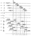
(トナー排出動作)
図3はトナー排出動作を説明するためのタイムチャートである。図において、a103〜d103はそれぞれ画像形成装置a〜dの静電潜像書き込み装置103の現像タイミングを示し、a,b,c,d102、a,b,c,d105、a,b,c,d106はそれぞれ帯電ローラ102、現像ローラ105、供給ローラ106の電圧を示し、a,b,c,d108はそれぞれ画像形成装置a〜dの転写ローラ108の電圧を示す。ここで、例えば所定の枚数N枚目の印刷データを露光した後トナーの排出動作を行う。
【0020】
図2における画像形成装置dのN枚目の露光が終了した直後、画像形成装置aの露光部103が露光を開始する。露光時間L1は任意のトナー排出量によって決定される。
【0021】
a103に示す露光開始時刻t1の感光体ドラム103の表面が転写ベルト110に接触する直前の時間L5が経過した時刻t2にa108に示す画像形成装置aの転写ローラ108に印加される電圧は0Vとなる。この為、感光体ドラム101に付着しているトナーの大半は転写ベルト通過後も感光体ドラム102に付着し続ける。感光体ドラムに付着しているトナーはクリーニングブレード107によりかきとられ、このクリーニングブレード107を収納するクリーニング装置内に収容される。
【0022】
一方、転写ローラ108に印加される電圧は時刻t2から時間L1の間−400Vのマイナス電圧となる。マイナス電圧が印加オフしている時間は、確実に感光体ドラム101上のトナーが転写ベルトに接触している間マイナスに印加させる為、マイナス印加時間を正規のL1よりも前後で長くするのが好ましい。尚、0Vであってもわずかの転写は発生するがトナーは概ね感光体ドラム101に付着したままの状態を維持することができる。従って、吐出電圧は0V〜−400Vの間から選択することができる。
【0023】
また、転写ベルトに一部付着したトナーが、画像形成装置b,c,dを通過する場合、各々の画像形成装置の転写ローラ108には、待機電圧が供給される。待機電圧とは、0Vと転写電圧の間の値をとり、転写電圧を印加することにより感光体ドラムへの影響を極力抑え,かつ、転写ベルト上に付着しているトナーを保持して、画像形成装置b、c、dの感光体ドラム101への再付着を抑える。
【0024】
b103に示す様に画像形成装置aの露光が終了する時刻t3から、転写ベルトが画像形成装置aから画像形成装置bに移動する時間L6が経過した時刻t4に画像形成装置bの露光部103が露光を開始する。以下、画像形成装置aと同様の動作が行われる。
【0025】
画像形成装置bの露光が終了する時刻t6から、転写ベルトが画像形成装置bから画像形成装置cに移動する時間L7が経過する時刻t7に画像形成装置cの露光部103が露光を開始する。以下、画像形成装置aと同様の動作が行われる。
【0026】
画像形成装置cの露光が終了する時刻t9から、転写ベルトが画像形成装置cから画像形成装置dに移動する時間L8が経過する時刻t10に画像形成装置dの露光部103が露光を開始する。以下、画像形成装置aと同様の動作が行われる。
【0027】
以上のような動作により、トナーカートリッジ113の廃トナー容器114に廃トナーを回収することが可能となる。
【0028】
(第1の実施の形態の効果)
以上のように、第1の実施例の動作により、現像装置内の劣化トナーを感光体ドラム101上に排出することにより、感光体側の廃トナーボックス特にトナーカートリッジ内の廃トナー容器に吐出トナーを回収することが可能となり、現像装置内特にトナー規制部材周辺にかたまった劣化トナーによる画像の劣化を防ぐことができる。
【0029】
本実施の形態においては、特に劣化トナーをトナーカートリッジ内の廃トナー容器中に回収するので、排出された劣化トナーはトナー補給と同時に交換されるので、このような劣化トナーの強制排出によりトナーを大量に排出しても廃トナーが廃トナー容器からあふれるおそれはない。
【0030】
また、これにより転写ベルト側の廃トナーボックスの容量を極端に大きくする必用がなくなる。
【0031】
(第2の実施の形態)
第1の実施の形態では、画像形成装置a〜dの全てでトナーを無条件に吐出する場合を説明した。しかし、実際には、印刷デューティが高い場合はトナーが劣化する前に現像されて排出されたり、劣化していても他の正常トナーとともに現像されて排出されるので、トナー排出が必要ない。
【0032】
本実施の形態におけるトナー排出は、図3のタイムチャートでトナーを排出するが、トナー排出は以下の動作のように調整する。尚、図1の画像形成装置の図示しない制御部には、上記印刷枚数をカウントするカウンタに加え、感光体ドラムの回転数をカウントするカウンタと、印刷ドットをカウントするカウンタとを有する。
【0033】
(トナー排出動作)
図4は、トナー吐出を行う場合のフローチャートを示す。
【0034】
図4において、画像形成装置a〜dの感光体ドラムの回転数をカウントしたカウンタ値をp、印刷ドット数をカウントしたカウンタ値をd、任意の感光体ドラムの回転数規定値をCp、任意の印刷ドット数規定値をCd、規定ドット数とドット数カウンタ値の差分をdifとする。
【0035】
s1において、感光体ドラムが回転するのを検知する。感光体ドラムが回転を始めると次のステップに進む。
【0036】
s2において、感光体ドラム回転数をカウンタpにカウントする。
【0037】
s3において、印刷ドット数をカウンタdにカウントする。
【0038】
s4において、感光体ドラム回転数カウンタの値が、任意に定めた感光体ドラムの回転数カウント値Cpに達しているかどうか判断する。達していない場合は、s1に戻る。達している場合は、s5に進む。
【0039】
s5では印刷ドット数カウンタ値cが任意の規定ドット数Cdに達しているか判断する。Cdの値は必要としている印刷デューティで感光体ドラム回転数p回転した場合のドット数カウント値である。達している場合は、s8に進む。 s5で印刷ドット数カウンタ値cが任意の規定ドット数Cdに達していない場合は、s6に進む。
【0040】
s6では、規定ドット数Cdと印刷ドット数カウンタ値cの差分difを求める。
【0041】
s7では、印刷の切れ目において、トナー吐出シーケンス(実施例1)に入り、dif分のトナー吐出を行う。トナー吐出が終了するとs8に進む。
【0042】
s8では、感光体ドラム回転数カウンタのカウント値pと印刷ドット数カウンタのカウント値dをクリアして、s1に進む。
【0043】
上記のフローを画像形成装置a〜dについて各々行う。
【0044】
(第2の実施の形態の効果)
以上のように、第2の実施の形態によれば、予め決めておいた感光体ドラムの規定回転数に対する平均デューティに達していない画像形成装置に対し、達していない差分だけトナーの吐出を行う事が可能となる。そのため、劣化したトナーを効果的に排出するが劣化していないトナーの排出を減らすことができる。
【0045】
(実施の形態の変形例)
第1の実施の形態では、トナー吐出のシーケンスについて、第2の実施の形態では、トナー吐出のアルゴリズムについて記述した。しかしながら、単純にトナーを吐出した場合、トナー消費量が多くなり、不経済となる。第3の実施の形態では、トナー消費量を抑えるトナー吐出のパターンについて述べる。
【0046】
第3の実施の形態において、画像形成装置の制御部は所定の印刷パターンを格納した記憶部を有する。図5は、トナー吐出パターンの一例である。
【0047】
図5に示すように、トナー吐出を行う場合、全面100%の吐出パターンを行うと、劣化トナーを効果的に排出することができる。しかし、トナーの使用部分、現像器内のトナーの還流状況により、トナーが劣化し易い位置がある。トナー劣化が少ない位置に対しても100%の吐出を行った場合、余分なトナーの吐出となる。また、トナー劣化が激しい部分のために、より多くのトナー吐出を行うと、更にトナー劣化があまりない部分は更に余分なトナー消費となってしまう。
【0048】
各部分におけるトナー劣化状況を更に具体的に説明する。図6は経時で使用した構成でハーフパターンを印刷した場合の印刷結果の一例である。印刷端部601において、画像濃度の不均一やドット再現性の低下が発生し易い。
【0049】
図6の現象を軽減する為に、図7に示すように吐き出し部分を701a,701b,701cに区切り、トナー劣化の多い部分に対してトナー吐出量を変える。一例として、図7では印刷可能領域の端部である701a,701cの部分に対しては100%のトナー吐出を行い、中央部の701bの部分に対しては50%のトナー吐出を行っている。
【0050】
このように、印刷可能領域の端部はデューティを高く、中央部はデューティを低くすることにより劣化トナーの多い端部のトナーをより多く排出することにより、劣化トナーを効率的に排出することができる。
【0051】
【発明の効果】
以上のように、本発明によれば、トナー劣化したトナーを効果的に排出することができるので印刷上の画像濃度の不均一やドット再現性の低下を抑える事が可能となる。
【図面の簡単な説明】
【図1】本発明の第1の実施の形態に用いる画像形成装置を説明するための要部断面図。
【図2】本発明の第1の実施の形態をカラープリンタに構成した場合の要部断面図。
【図3】本発明の第1の実施の形態の動作を説明するためのタイミングチャート。
【図4】本発明の第2の実施の形態を説明するためのフローチャート。
【図5】本発明におけるトナー排出パターンの一例。
【図6】印刷状態の一例。
【図7】本発明に用いる印刷パターンの変形例。
【符号の説明】
100:画像形成装置
101:感光体ドラム
102:帯電ローラ
103:静電潜像書き込み装置
104:トナー規制部材
105:現像ローラ
106:供給ローラ
107:クリーニングブレード
108:転写ローラ
109:現像装置
113:トナーカートリッジ
114:廃トナー容器[0001]
BACKGROUND OF THE INVENTION
The present invention relates to a cleaning method in an image forming apparatus.
[0002]
[Prior art]
In an image forming apparatus such as a printer or a copying machine, an electrophotographic method is increasingly used because of a high printing speed and good storability of a printed image.
[0003]
In an electrophotographic image forming apparatus, a toner made of powdered resin is used as a developer, which is uniformly leveled on the developing roller of the developing apparatus, and the uniformly leveled toner is selectively selected from the developing roller. Then, it is attached to a photosensitive member such as a photosensitive drum and then transferred onto a printing medium such as paper to form an image. This image is fixed on the print medium by a heat fixing device.
[0004]
[Problems to be solved by the invention]
The toner used in such an electrophotographic image forming apparatus has a physical pressure and frictional heat associated with the physical pressure when uniformly leveled on the developing device as described above. The toner is not transferred from the toner and is destroyed by the physical pressure during friction between each roller or the frictional heat associated therewith, or it is pressed against other toner to be integrated into a large lump and printed. Deteriorates as it progresses. Such deteriorated toner accumulates in the developing device, causing problems such as non-uniform image density, reduced dot reproducibility, or so-called fogging in the printed image.
[0005]
[Means for Solving the Problems]
The present invention relates to a toner discharging method applied to an image forming apparatus having a photosensitive member, a charging device, an electrostatic latent image writing device, a developing device, a transfer device, and a cleaning device, and when the photosensitive member reaches a predetermined number of rotations. As the toner discharging operation, the photosensitive member is charged by the charging device, and the photosensitive member reaches the predetermined rotational speed when the photosensitive member is rotated by the predetermined rotational speed at a predetermined printing duty. A difference amount with respect to the number of printed dots printed so far, and the electrostatic latent image writing device writes an electrostatic latent image pattern on which the toner corresponding to the difference amount adheres to the charged photosensitive member, and the developing device The toner is discharged from the developing device by supplying the toner to the photosensitive member from the developing device, and a voltage having the same polarity as the toner is applied to the transfer device. A toner discharge method characterized by removing the toner from the photoreceptor by contacting the grayed device to the photosensitive member.
[0008]
DETAILED DESCRIPTION OF THE INVENTION
(First embodiment)
(Description of image forming apparatus)
FIG. 1 is a diagram illustrating a main part of an image forming apparatus for illustrating the first embodiment. The image forming apparatus 100 includes a drum-type image carrier (hereinafter referred to as a photosensitive drum) 101, a conductive rubber roller (hereinafter referred to as a charging roller) 102 that rotates in contact with the photosensitive drum 101, and a photosensitive member. An electrostatic latent image writing device 103 that selectively exposes the drum 101, a toner regulating member 104 that keeps the toner amount on the developing roller constant, and a toner carrier that supplies toner to the photosensitive drum (hereinafter referred to as a developing roller). 105) 105, a supply roller 106 that supplies toner to the developing roller, a cleaning blade 107 that scrapes residual toner on the photosensitive drum 101, a transfer roller 108 that transfers toner to the recording paper 111, and a transfer belt that conveys the recording paper 111 110 and a charging roller 102, a developing roller 105, a supply roller 106, and a transfer roller 108 that supply voltage to the transfer roller 108 (not shown). It is composed of a not shown control unit for controlling the respective units and.
[0009]
As the photosensitive drum 101, for example, an organic photosensitive drum is used. As the charging roller 102, a silicone resin or a urethane resin roller can be used. The electrostatic latent image writing device can use a laser or a light emitting diode (LED) array head. The developing roller 105 can use silicone resin or urethane resin. The supply roller 106 can use foamed resin such as urethane.
[0010]
A toner cartridge 113 that supplies toner to the developing device 109 is detachably connected to the developing device 109 including the toner regulating member 104, the developing roller 105, and the supply roller. The toner cartridge 113 has a waste toner container 114 therein, and the collected waste toner can be taken out from the image forming apparatus 100 simultaneously with the replacement of the toner cartridge.
[0011]
As the toner supplied from the toner cartridge, for example, a capsule toner having a particle diameter of 5 to 7 μm can be used. For example, the capsule toner is configured so that it melts easily at high temperatures during fixing, but does not easily fuse with the surrounding toner during storage by enclosing the resin with a low glass transition temperature on the inside with a resin with a high glass transition temperature on the outside. Has been.
[0012]
The control unit (not shown) of the image forming apparatus 100 is provided with a counter that counts the number of printed sheets.
[0013]
Next, the operation will be described. The photosensitive drum 101, the rollers 102, 105, and 108 and the transfer belt 110 are rotationally driven by a motor (not shown), and the recording paper 111 is fed by a paper feeding mechanism (not shown). The photosensitive drum 101 rotates in the direction of arrow A, the charging roller 102 rotates in the direction of arrow B, the developing roller 105 rotates in the direction of arrow C, the transfer belt 110 rotates in the direction of arrow D, and the recording paper 111 Is assumed to travel in the direction of arrow E.
[0014]
(Printing operation)
First, the photosensitive drum 101 is uniformly charged to a predetermined surface potential, for example, −850 V by contact with the charging roller 102 when the charging roller 102 is supplied with a negative voltage of, for example, −1350 V from a power supply device (not shown). The The uniformly charged surface of the photosensitive drum 101 reaches below the electrostatic latent image writing device 103 due to the rotation in the arrow A direction. Depending on the image to be formed, the electrostatic latent image writing device 103 selectively exposes the surface potential of the photosensitive drum 101 in the portion where the electrostatic latent image is written, which is about −50 V. Is also close to 0V.
[0015]
The surface of the photosensitive drum 101 that has completed writing of the electrostatic latent image comes into contact with the developing roller 105 by the rotation in the arrow A direction. The developing roller 105 contacts the photosensitive drum 101 with a predetermined pressure and rotates in the direction of arrow C. The toner on the developing roller 105 is thinned by the toner regulating member 104, and moves on the photosensitive drum 101 by contact with the photosensitive drum 101 by the rotation of the developing roller 105 to perform development. Here, the developing method is reversal development in which the toner has a charge of the same polarity as that of the uniformly charged polarity of the photosensitive drum 101, and a negative voltage is applied to the developing roller 105 from a power source (not shown). The toner is developed on the photosensitive drum 101.
[0016]
The surface of the photosensitive drum 101 that has been developed comes into contact with the transfer belt 110 by the rotation in the arrow A direction. The transfer belt 110 is configured to contact the photoconductor 101 with a predetermined pressure and move in the direction of arrow D at the same speed. A positive voltage of +1500 V, for example, is supplied to the transfer belt 110 by a power source (not shown), and the toner on the photosensitive drum 101 is transferred by moving to the recording paper 111 traveling in the direction of arrow E. The recording paper 111 after transfer is separated from the photosensitive drum 101.
[0017]
As shown in FIG. 2, in the case of a tandem type color printer, four image forming apparatuses a, b, c, and d in FIG. 1 are arranged, and after the transfer of the image forming apparatus d is completed, it is inserted into a fixing device (not shown) and fixed. After completion, the printed matter is discharged out of the image forming apparatus.
[0018]
After the transfer is completed in the image forming apparatus of FIG. 1, a part of the toner remains as untransferred toner on the surface of the photosensitive drum 101, but the surface of the photosensitive drum 101 continues to be untransferred by rotation in the direction of arrow A. It contacts the cleaning blade 107 together with the toner. Untransferred toner on the photosensitive drum 101 is scraped off by the cleaning blade 107. That is, the untransferred toner is removed from the photosensitive drum 101. The photosensitive drum 101, from which the untransferred toner has been removed, continues to rotate in the direction of arrow A and enters the charging process again.
[0019]
(Toner discharge operation)
FIG. 3 is a time chart for explaining the toner discharging operation. In the figure, a103 to d103 respectively indicate the development timing of the electrostatic latent image writing device 103 of the image forming apparatuses a to d, and a, b, c, d102, a, b, c, d105, a, b, c, d106 indicates the voltages of the charging roller 102, the developing roller 105, and the supply roller 106, respectively, and a, b, c, and d108 indicate the voltages of the transfer rollers 108 of the image forming apparatuses a to d, respectively. Here, for example, a toner discharge operation is performed after exposing a predetermined number N of print data.
[0020]
Immediately after the Nth exposure of the image forming apparatus d in FIG. 2 is completed, the exposure unit 103 of the image forming apparatus a starts the exposure. The exposure time L1 is determined by an arbitrary toner discharge amount.
[0021]
The voltage applied to the transfer roller 108 of the image forming apparatus a indicated by a108 at time t2 when the time L5 immediately before the surface of the photosensitive drum 103 at the exposure start time t1 indicated by a103 contacts the transfer belt 110 has elapsed is 0V. Become. For this reason, most of the toner adhering to the photosensitive drum 101 continues to adhere to the photosensitive drum 102 even after passing through the transfer belt. The toner adhering to the photosensitive drum is scraped off by the cleaning blade 107 and stored in a cleaning device that stores the cleaning blade 107 .
[0022]
On the other hand, the voltage applied to the transfer roller 108 becomes a minus voltage of −400 V from time t2 to time L1. The time during which the negative voltage is turned off is applied negatively while the toner on the photosensitive drum 101 is in contact with the transfer belt, so that the negative application time should be longer before and after the normal L1. preferable. Note that although the transfer is slight even at 0 V, the toner can be maintained in a state where it is generally attached to the photosensitive drum 101. Therefore, the discharge voltage can be selected from 0V to -400V.
[0023]
Further, when the toner partially attached to the transfer belt passes through the image forming apparatuses b, c, and d, a standby voltage is supplied to the transfer roller 108 of each image forming apparatus. The standby voltage takes a value between 0 V and the transfer voltage. By applying the transfer voltage, the influence on the photosensitive drum is suppressed as much as possible, and the toner adhering to the transfer belt is held and the image is held. Reattachment of the forming apparatuses b, c, d to the photosensitive drum 101 is suppressed.
[0024]
As shown at b103, the exposure unit 103 of the image forming apparatus b performs the time t4 when the time L6 when the transfer belt moves from the image forming apparatus a to the image forming apparatus b has elapsed from the time t3 when the exposure of the image forming apparatus a ends. Start exposure. Thereafter, the same operation as that of the image forming apparatus a is performed.
[0025]
The exposure unit 103 of the image forming apparatus c starts exposure at time t7 when the time L7 when the transfer belt moves from the image forming apparatus b to the image forming apparatus c elapses from time t6 when the exposure of the image forming apparatus b ends. Thereafter, the same operation as that of the image forming apparatus a is performed.
[0026]
The exposure unit 103 of the image forming apparatus d starts exposure at time t10 when the time L8 when the transfer belt moves from the image forming apparatus c to the image forming apparatus d elapses from time t9 when the exposure of the image forming apparatus c ends. Thereafter, the same operation as that of the image forming apparatus a is performed.
[0027]
Through the above operation , waste toner can be collected in the waste toner container 114 of the toner cartridge 113.
[0028]
(Effects of the first embodiment)
As described above, the deteriorated toner in the developing device is discharged onto the photosensitive drum 101 by the operation of the first embodiment, so that the discharged toner is discharged to the waste toner box on the photosensitive member side, particularly the waste toner container in the toner cartridge. It is possible to collect the image, and it is possible to prevent image deterioration due to deteriorated toner accumulated in the developing device, particularly around the toner regulating member.
[0029]
In the present embodiment, particularly, the deteriorated toner is collected in a waste toner container in the toner cartridge. Therefore, the discharged deteriorated toner is replaced at the same time as the replenishment of the toner. there is no possibility that the waste toner overflows from the waste toner container even if the large amount of emissions.
[0030]
This eliminates the need to extremely increase the capacity of the waste toner box on the transfer belt side.
[0031]
(Second Embodiment)
In a first implementation embodiment has been described a case of ejecting the toner unconditionally all the image forming apparatus to d. However, in practice, or if the print duty high is discharged is developed before the toner is deteriorated, because even if degraded is discharged been developed with other normal toner, the toner discharge is not required.
[0032]
In this embodiment, the toner is discharged according to the time chart of FIG. 3, and the toner discharge is adjusted as follows. The control unit (not shown) of the image forming apparatus shown in FIG. 1 includes a counter for counting the number of rotations of the photosensitive drum and a counter for counting printing dots in addition to the counter for counting the number of printed sheets.
[0033]
(Toner discharge operation)
FIG. 4 is a flowchart for the toner ejection.
[0034]
In FIG. 4, p is a counter value obtained by counting the number of rotations of the photosensitive drums of the image forming apparatuses a to d, d is a counter value obtained by counting the number of printed dots, and Cp is a predetermined value for the number of rotations of any photosensitive drum. Is defined as Cd, and the difference between the specified dot number and the dot number counter value is dif.
[0035]
In s1, the rotation of the photosensitive drum is detected. When the photosensitive drum starts to rotate, the process proceeds to the next step.
[0036]
In s2, the number of revolutions of the photosensitive drum is counted by the counter p.
[0037]
In s3, the number of print dots is counted in the counter d.
[0038]
In s4, it is determined whether or not the value of the photosensitive drum rotation number counter reaches an arbitrarily determined photosensitive drum rotation number count Cp. If not, return to s1. If so, go to s5.
[0039]
In s5, it is determined whether the print dot number counter value c has reached an arbitrary specified dot number Cd. The value of Cd is a dot number count value when the photosensitive drum is rotated by p at the required printing duty. If so, go to s8. If the printing dot number counter value c has not reached the arbitrary prescribed dot number Cd in s5, the process proceeds to s6.
[0040]
In s6, a difference dif between the specified dot number Cd and the print dot number counter value c is obtained.
[0041]
In s7, the toner discharge sequence (Example 1) is entered at the break of printing, and dif toner is discharged. When toner ejection is completed, the process proceeds to s8.
[0042]
In s8, the count value p of the photosensitive drum rotation number counter and the count value d of the printing dot number counter are cleared, and the process proceeds to s1.
[0043]
The above flow is performed for each of the image forming apparatuses a to d.
[0044]
(Effect of the second embodiment)
As described above, according to the second embodiment, toner is discharged by a difference that has not been reached to an image forming apparatus that has not reached the average duty with respect to a predetermined number of rotations of the photosensitive drum. Things will be possible. For this reason, it is possible to effectively discharge the deteriorated toner but reduce the discharge of the toner that has not deteriorated.
[0045]
(Modification of the embodiment)
In the first embodiment, the toner discharge sequence is described. In the second embodiment, the toner discharge algorithm is described. However, when toner is simply ejected, the amount of toner consumption increases, which is uneconomical. In the third embodiment, a toner discharge pattern for suppressing toner consumption will be described.
[0046]
In the third embodiment, the control unit of the image forming apparatus includes a storage unit that stores a predetermined print pattern. FIG. 5 is an example of a toner discharge pattern.
[0047]
As shown in FIG. 5, when toner is discharged, a deteriorated toner can be effectively discharged by performing a 100% discharge pattern on the entire surface. However, there is a position where the toner is likely to be deteriorated depending on a portion where the toner is used and a state of recirculation of toner in the developing device. If 100% ejection is performed even at a position where toner deterioration is small, excess toner is ejected. Further, if more toner is ejected due to a portion where the toner is severely deteriorated, a portion where there is not much toner deterioration further consumes extra toner.
[0048]
The toner deterioration state in each part will be described more specifically. FIG. 6 is an example of a printing result when a half pattern is printed with a configuration used over time. In the
[0049]
In order to reduce the phenomenon of FIG. 6, the discharge portion is divided into 701a, 701b and 701c as shown in FIG. As an example, in FIG. 7, 100% toner discharge is performed on the
[0050]
As described above, by increasing the duty at the end of the printable area and decreasing the duty at the center, the discharged toner can be efficiently discharged by discharging a larger amount of the toner at the end with much deteriorated toner. it can.
[0051]
【The invention's effect】
As described above, according to the present invention, toner with deteriorated toner can be effectively discharged, so that it is possible to suppress non-uniform image density on printing and a decrease in dot reproducibility.
[Brief description of the drawings]
FIG. 1 is a cross-sectional view of a main part for explaining an image forming apparatus used in a first embodiment of the present invention.
FIG. 2 is a cross-sectional view of a main part when the first embodiment of the present invention is configured in a color printer.
FIG. 3 is a timing chart for explaining the operation of the first exemplary embodiment of the present invention.
FIG. 4 is a flowchart for explaining a second embodiment of the present invention;
FIG. 5 shows an example of a toner discharge pattern in the present invention.
FIG. 6 shows an example of a printing state.
FIG. 7 shows a modified example of a print pattern used in the present invention.
[Explanation of symbols]
100: Image forming apparatus 101: photosensitive drum 102: charging roller 103: electrostatic latent image writing device 104: toner regulating member 105: the developing roller 106: feed roller 107: a cleaning blade 108: transfer roller 109: developing equipment 113: Toner cartridge 114: waste toner container
Claims (2)
前記感光体が所定の回転数に達するとトナー排出動作として、
前記帯電装置により前記感光体を帯電し、
所定の印刷デューティで前記感光体を前記所定の回転数だけ回転した場合の規定ドット数と前記感光体が前記所定の回転数に達するまでに印刷した印刷ドット数との差分量を算出し、
前記静電潜像書き込み装置により前記帯電した感光体に、前記差分量分のトナーが付着する静電潜像パターンを書き込み、
前記現像装置からトナーを前記感光体に供給して現像することにより前記現像装置からトナーを排出し、
前記転写装置に前記トナーと同極性の電圧を印加し、
前記クリーニング装置を感光体に接触させることにより前記感光体からトナーを除去することを特徴とするトナー排出方法。In a toner discharging method applied to an image forming apparatus having a photoreceptor, a charging device, an electrostatic latent image writing device, a developing device, a transfer device, and a cleaning device,
When the photosensitive member reaches a predetermined rotational speed , as a toner discharging operation,
Charging the photoreceptor with the charging device;
Calculating the amount of difference between the prescribed number of dots when the photosensitive member is rotated by the predetermined rotational speed at a predetermined printing duty and the number of printed dots printed until the photosensitive member reaches the predetermined rotational speed ;
Write an electrostatic latent image pattern in which the difference amount of toner adheres to the charged photosensitive member by the electrostatic latent image writing device;
The toner is discharged from the developing device by supplying toner from the developing device to the photosensitive member and developing the toner,
Apply a voltage of the same polarity as the toner to the transfer device,
A toner discharging method comprising: removing toner from the photosensitive member by bringing the cleaning device into contact with the photosensitive member.
前記静電潜像パターンは印刷エリア中央より印刷エリア端部の印刷ドット数が大きいことを特徴とするトナー排出方法。The toner discharging method according to claim 1.
The toner discharging method according to claim 1, wherein the electrostatic latent image pattern has a larger number of print dots at a print area end than at a print area center.
Priority Applications (2)
| Application Number | Priority Date | Filing Date | Title |
|---|---|---|---|
| JP2002199611A JP4414635B2 (en) | 2002-07-09 | 2002-07-09 | Toner discharge method |
| US10/304,010 US6766121B2 (en) | 2001-11-26 | 2002-11-26 | Image forming apparatus that periodically discharges waste toner and method of operation thereof |
Applications Claiming Priority (1)
| Application Number | Priority Date | Filing Date | Title |
|---|---|---|---|
| JP2002199611A JP4414635B2 (en) | 2002-07-09 | 2002-07-09 | Toner discharge method |
Publications (3)
| Publication Number | Publication Date |
|---|---|
| JP2004045481A JP2004045481A (en) | 2004-02-12 |
| JP2004045481A5 JP2004045481A5 (en) | 2005-08-04 |
| JP4414635B2 true JP4414635B2 (en) | 2010-02-10 |
Family
ID=31706700
Family Applications (1)
| Application Number | Title | Priority Date | Filing Date |
|---|---|---|---|
| JP2002199611A Expired - Fee Related JP4414635B2 (en) | 2001-11-26 | 2002-07-09 | Toner discharge method |
Country Status (1)
| Country | Link |
|---|---|
| JP (1) | JP4414635B2 (en) |
Families Citing this family (12)
| Publication number | Priority date | Publication date | Assignee | Title |
|---|---|---|---|---|
| JP4436383B2 (en) | 2007-03-29 | 2010-03-24 | 株式会社沖データ | Image forming apparatus |
| US8005381B2 (en) | 2007-09-26 | 2011-08-23 | Oki Data Corporation | Image forming apparatus |
| JP4598045B2 (en) | 2007-11-13 | 2010-12-15 | 株式会社沖データ | Image forming apparatus and image forming apparatus cleaning method |
| JP2009251202A (en) | 2008-04-04 | 2009-10-29 | Oki Data Corp | Image forming apparatus |
| JP2009288698A (en) | 2008-05-30 | 2009-12-10 | Oki Data Corp | Image forming apparatus |
| JP5386459B2 (en) * | 2010-10-12 | 2014-01-15 | 京セラドキュメントソリューションズ株式会社 | Image forming apparatus |
| JP5659183B2 (en) | 2012-03-26 | 2015-01-28 | 株式会社沖データ | Image forming apparatus and image forming method |
| JP6219159B2 (en) * | 2013-12-20 | 2017-10-25 | 株式会社沖データ | Image forming apparatus |
| JP2017067975A (en) | 2015-09-30 | 2017-04-06 | 株式会社沖データ | Image formation device |
| JP7027186B2 (en) * | 2018-02-02 | 2022-03-01 | キヤノン株式会社 | Image forming device |
| JP7298556B2 (en) | 2020-06-30 | 2023-06-27 | 信越化学工業株式会社 | Photomask blank manufacturing method |
| US11888475B2 (en) | 2021-05-24 | 2024-01-30 | Oki Electric Industry Co., Ltd. | Integrated circuit, circuit board, and electronic apparatus |
-
2002
- 2002-07-09 JP JP2002199611A patent/JP4414635B2/en not_active Expired - Fee Related
Also Published As
| Publication number | Publication date |
|---|---|
| JP2004045481A (en) | 2004-02-12 |
Similar Documents
| Publication | Publication Date | Title |
|---|---|---|
| JP2008281844A (en) | Development method, developer, image forming method, image forming apparatus, calculation device for amount of consumption, and process cartridge | |
| JP4414635B2 (en) | Toner discharge method | |
| JP5683155B2 (en) | Image forming apparatus | |
| JPH10186852A (en) | Electrophotographic image forming device | |
| US8488985B2 (en) | Image forming apparatus and method for applying transfer voltage in the image forming apparatus | |
| JP2009244439A (en) | Developing device and image forming apparatus | |
| JP2007316532A (en) | Developing device and image forming apparatus | |
| JP2006337605A (en) | Image forming apparatus | |
| JP6200834B2 (en) | Image forming apparatus | |
| JP4708807B2 (en) | Electrophotographic image forming apparatus | |
| JPH07114319A (en) | Image forming device | |
| JP2009244438A (en) | Developing device and image forming apparatus equipped with developing device | |
| JP2007322634A (en) | Image forming apparatus | |
| JP4821099B2 (en) | Image forming apparatus | |
| JP2004219654A (en) | Image forming apparatus | |
| JP2003173074A (en) | Electrophotographic printer and its printing control method | |
| JP4335201B2 (en) | Developing device and image forming apparatus | |
| JP7318454B2 (en) | Image forming apparatus and image forming method | |
| JP2005099663A (en) | Developing device for image forming apparatus and operating method for the developing device | |
| JP2012141444A (en) | Image forming apparatus | |
| JP2009133982A (en) | Development apparatus and image forming apparatus | |
| JP6490568B2 (en) | Image forming apparatus | |
| JP2024044678A (en) | Image forming device | |
| JP2005107054A (en) | Image forming apparatus | |
| JP5420921B2 (en) | Image forming apparatus |
Legal Events
| Date | Code | Title | Description |
|---|---|---|---|
| A521 | Written amendment |
Free format text: JAPANESE INTERMEDIATE CODE: A523 Effective date: 20041224 |
|
| A621 | Written request for application examination |
Free format text: JAPANESE INTERMEDIATE CODE: A621 Effective date: 20041224 |
|
| RD02 | Notification of acceptance of power of attorney |
Free format text: JAPANESE INTERMEDIATE CODE: A7422 Effective date: 20061025 |
|
| A977 | Report on retrieval |
Free format text: JAPANESE INTERMEDIATE CODE: A971007 Effective date: 20070417 |
|
| A131 | Notification of reasons for refusal |
Free format text: JAPANESE INTERMEDIATE CODE: A131 Effective date: 20070508 |
|
| A521 | Written amendment |
Free format text: JAPANESE INTERMEDIATE CODE: A523 Effective date: 20070706 |
|
| A02 | Decision of refusal |
Free format text: JAPANESE INTERMEDIATE CODE: A02 Effective date: 20070807 |
|
| A521 | Written amendment |
Free format text: JAPANESE INTERMEDIATE CODE: A523 Effective date: 20071004 |
|
| A911 | Transfer of reconsideration by examiner before appeal (zenchi) |
Free format text: JAPANESE INTERMEDIATE CODE: A911 Effective date: 20071015 |
|
| A912 | Removal of reconsideration by examiner before appeal (zenchi) |
Free format text: JAPANESE INTERMEDIATE CODE: A912 Effective date: 20071102 |
|
| A521 | Written amendment |
Free format text: JAPANESE INTERMEDIATE CODE: A523 Effective date: 20090508 |
|
| A521 | Written amendment |
Free format text: JAPANESE INTERMEDIATE CODE: A523 Effective date: 20090728 |
|
| A01 | Written decision to grant a patent or to grant a registration (utility model) |
Free format text: JAPANESE INTERMEDIATE CODE: A01 |
|
| A61 | First payment of annual fees (during grant procedure) |
Free format text: JAPANESE INTERMEDIATE CODE: A61 Effective date: 20091120 |
|
| FPAY | Renewal fee payment (event date is renewal date of database) |
Free format text: PAYMENT UNTIL: 20121127 Year of fee payment: 3 |
|
| R150 | Certificate of patent or registration of utility model |
Ref document number: 4414635 Country of ref document: JP Free format text: JAPANESE INTERMEDIATE CODE: R150 Free format text: JAPANESE INTERMEDIATE CODE: R150 |
|
| FPAY | Renewal fee payment (event date is renewal date of database) |
Free format text: PAYMENT UNTIL: 20121127 Year of fee payment: 3 |
|
| FPAY | Renewal fee payment (event date is renewal date of database) |
Free format text: PAYMENT UNTIL: 20131127 Year of fee payment: 4 |
|
| LAPS | Cancellation because of no payment of annual fees |