JP2018133276A - connector - Google Patents

connector Download PDF

Info

Publication number
JP2018133276A
JP2018133276A JP2017027672A JP2017027672A JP2018133276A JP 2018133276 A JP2018133276 A JP 2018133276A JP 2017027672 A JP2017027672 A JP 2017027672A JP 2017027672 A JP2017027672 A JP 2017027672A JP 2018133276 A JP2018133276 A JP 2018133276A
Authority
JP
Japan
Prior art keywords
conductor
dielectric
front wall
holding member
main body
Prior art date
Legal status (The legal status is an assumption and is not a legal conclusion. Google has not performed a legal analysis and makes no representation as to the accuracy of the status listed.)
Pending
Application number
JP2017027672A
Other languages
Japanese (ja)
Other versions
JP2018133276A5 (en
Inventor
哲矢 宮村
Tetsuya Miyamura
哲矢 宮村
康雄 大森
Yasuo Omori
康雄 大森
Current Assignee (The listed assignees may be inaccurate. Google has not performed a legal analysis and makes no representation or warranty as to the accuracy of the list.)
Sumitomo Wiring Systems Ltd
AutoNetworks Technologies Ltd
Sumitomo Electric Industries Ltd
Original Assignee
Sumitomo Wiring Systems Ltd
AutoNetworks Technologies Ltd
Sumitomo Electric Industries Ltd
Priority date (The priority date is an assumption and is not a legal conclusion. Google has not performed a legal analysis and makes no representation as to the accuracy of the date listed.)
Filing date
Publication date
Application filed by Sumitomo Wiring Systems Ltd, AutoNetworks Technologies Ltd, Sumitomo Electric Industries Ltd filed Critical Sumitomo Wiring Systems Ltd
Priority to JP2017027672A priority Critical patent/JP2018133276A/en
Priority to PCT/JP2018/002664 priority patent/WO2018150854A1/en
Priority to US16/486,916 priority patent/US10770838B2/en
Priority to CN201880011214.5A priority patent/CN110301072B/en
Publication of JP2018133276A publication Critical patent/JP2018133276A/en
Publication of JP2018133276A5 publication Critical patent/JP2018133276A5/ja
Pending legal-status Critical Current

Links

Images

Classifications

    • HELECTRICITY
    • H01ELECTRIC ELEMENTS
    • H01RELECTRICALLY-CONDUCTIVE CONNECTIONS; STRUCTURAL ASSOCIATIONS OF A PLURALITY OF MUTUALLY-INSULATED ELECTRICAL CONNECTING ELEMENTS; COUPLING DEVICES; CURRENT COLLECTORS
    • H01R13/00Details of coupling devices of the kinds covered by groups H01R12/70 or H01R24/00 - H01R33/00
    • H01R13/46Bases; Cases
    • H01R13/502Bases; Cases composed of different pieces
    • H01R13/506Bases; Cases composed of different pieces assembled by snap action of the parts
    • HELECTRICITY
    • H01ELECTRIC ELEMENTS
    • H01RELECTRICALLY-CONDUCTIVE CONNECTIONS; STRUCTURAL ASSOCIATIONS OF A PLURALITY OF MUTUALLY-INSULATED ELECTRICAL CONNECTING ELEMENTS; COUPLING DEVICES; CURRENT COLLECTORS
    • H01R13/00Details of coupling devices of the kinds covered by groups H01R12/70 or H01R24/00 - H01R33/00
    • H01R13/62Means for facilitating engagement or disengagement of coupling parts or for holding them in engagement
    • H01R13/629Additional means for facilitating engagement or disengagement of coupling parts, e.g. aligning or guiding means, levers, gas pressure electrical locking indicators, manufacturing tolerances
    • HELECTRICITY
    • H01ELECTRIC ELEMENTS
    • H01RELECTRICALLY-CONDUCTIVE CONNECTIONS; STRUCTURAL ASSOCIATIONS OF A PLURALITY OF MUTUALLY-INSULATED ELECTRICAL CONNECTING ELEMENTS; COUPLING DEVICES; CURRENT COLLECTORS
    • H01R13/00Details of coupling devices of the kinds covered by groups H01R12/70 or H01R24/00 - H01R33/00
    • H01R13/40Securing contact members in or to a base or case; Insulating of contact members
    • H01R13/42Securing in a demountable manner
    • H01R13/426Securing by a separate resilient retaining piece supported by base or case, e.g. collar or metal contact-retention clip
    • HELECTRICITY
    • H01ELECTRIC ELEMENTS
    • H01RELECTRICALLY-CONDUCTIVE CONNECTIONS; STRUCTURAL ASSOCIATIONS OF A PLURALITY OF MUTUALLY-INSULATED ELECTRICAL CONNECTING ELEMENTS; COUPLING DEVICES; CURRENT COLLECTORS
    • H01R13/00Details of coupling devices of the kinds covered by groups H01R12/70 or H01R24/00 - H01R33/00
    • H01R13/646Details of coupling devices of the kinds covered by groups H01R12/70 or H01R24/00 - H01R33/00 specially adapted for high-frequency, e.g. structures providing an impedance match or phase match
    • H01R13/6473Impedance matching
    • H01R13/6477Impedance matching by variation of dielectric properties
    • HELECTRICITY
    • H01ELECTRIC ELEMENTS
    • H01RELECTRICALLY-CONDUCTIVE CONNECTIONS; STRUCTURAL ASSOCIATIONS OF A PLURALITY OF MUTUALLY-INSULATED ELECTRICAL CONNECTING ELEMENTS; COUPLING DEVICES; CURRENT COLLECTORS
    • H01R24/00Two-part coupling devices, or either of their cooperating parts, characterised by their overall structure
    • H01R24/58Contacts spaced along longitudinal axis of engagement
    • HELECTRICITY
    • H01ELECTRIC ELEMENTS
    • H01RELECTRICALLY-CONDUCTIVE CONNECTIONS; STRUCTURAL ASSOCIATIONS OF A PLURALITY OF MUTUALLY-INSULATED ELECTRICAL CONNECTING ELEMENTS; COUPLING DEVICES; CURRENT COLLECTORS
    • H01R13/00Details of coupling devices of the kinds covered by groups H01R12/70 or H01R24/00 - H01R33/00
    • H01R13/646Details of coupling devices of the kinds covered by groups H01R12/70 or H01R24/00 - H01R33/00 specially adapted for high-frequency, e.g. structures providing an impedance match or phase match
    • H01R13/6461Means for preventing cross-talk
    • H01R13/6463Means for preventing cross-talk using twisted pairs of wires

Abstract

PROBLEM TO BE SOLVED: To achieve both improvement in communication performance and improvement in reliability of fitting operation.SOLUTION: A connector 1 includes: a dielectric body 10 having a plurality of conductor accommodation chambers 17 which are divided into right and left by a partition wall part 15; a plurality of inner conductors 36 housed individually into the plurality of conductor accommodation chambers 17; a synthetic resin-made body member 11 which forms the dielectric body 10 and in which the partition wall part 15 and the plurality of conductor accommodation chambers 17 are formed; and a synthetic resin-made front wall member 28 which forms the dielectric body 10 and is attached to the front end of the body member 11 so as to close an opening of the front end of the conductor accommodation chamber 17. A material or its quality of the partition wall part 15 is lower in dielectric constant than the material or its quality of the front wall member 28, and the material or its quality of the front wall member 28 is stronger in mechanical strength than the material or its quality of the wall partition part 15.SELECTED DRAWING: Figure 3

Description

本発明は、コネクタに関するものである。   The present invention relates to a connector.

特許文献1には、雄側誘電体に雄形内導体を取り付け、雌側誘電体に雌形内導体を取り付け、雌雄両誘電体を嵌合することにより、雄形内導体と雌形内導体を接続するようにしたコネクタが開示されている。   In Patent Document 1, a male inner conductor is attached to a male dielectric, a female inner conductor is attached to a female dielectric, and both male and female dielectrics are fitted to each other, whereby a male inner conductor and a female inner conductor are fitted. A connector is disclosed that connects the two.

特開2012−129103号公報JP 2012-129103 A

この種のコネクタとして、雌側誘電体に隔壁で区画された複数の導体収容室を形成し、複数の導体収容室に複数の雌側内導体を個別に収容する形態のものも考えられる。このようなコネクタを通信回路に適用した場合、通信性能を保証するために、雌側誘電体を誘電率の低い合成樹脂材料とすることが好ましい。ところが、誘電率の低い合成樹脂材料は比較的強度が低い。そのため、雌雄両誘電体を嵌合する過程で、雄形内導体の先端の細長いタブが雌側誘電体の正面と干渉したときに、タブが雌側誘電体の正面に突き刺さることが懸念される。   As this type of connector, a configuration is also conceivable in which a plurality of conductor accommodating chambers partitioned by partition walls are formed in a female dielectric, and a plurality of female inner conductors are individually accommodated in the plurality of conductor accommodating chambers. When such a connector is applied to a communication circuit, it is preferable that the female-side dielectric is made of a synthetic resin material having a low dielectric constant in order to guarantee communication performance. However, a synthetic resin material having a low dielectric constant has a relatively low strength. Therefore, in the process of fitting both male and female dielectrics, when the elongated tab at the tip of the male inner conductor interferes with the front of the female dielectric, the tab may pierce the front of the female dielectric. .

本発明は上記のような事情に基づいて完成されたものであって、通信性能の向上と嵌合動作の信頼性向上とを両立させることを目的とする。   The present invention has been completed based on the above circumstances, and an object thereof is to achieve both improvement in communication performance and improvement in reliability of fitting operation.

本発明は、
隔壁部で左右に区画された複数の導体収容室を有する誘電体と、
前記複数の導体収容室に個別に収容された複数の内導体と、
前記誘電体を構成し、前記隔壁部と前記複数の導体収容室とが形成された合成樹脂製の本体部材と、
前記誘電体を構成し、前記導体収容室の前端の開口を塞ぐように前記本体部材の前端部に取り付けられた合成樹脂製の前壁部材と、
前記前壁部材に形成され、前記誘電体の前方から相手側内導体のタブを前記導体収容室内に挿入させることを許容するタブ挿入口とを備え、
前記隔壁部の材料又は材質が、前記前壁部材より誘電率の低い材料又は材質であり、
前記前壁部材の材料又は材質が、前記隔壁部より機械的強度の高い材料又は材質であるところに特徴を有する。
The present invention
A dielectric having a plurality of conductor containing chambers divided on the left and right by a partition wall;
A plurality of inner conductors individually housed in the plurality of conductor housing chambers;
A body member made of a synthetic resin, which constitutes the dielectric, and in which the partition wall portion and the plurality of conductor accommodating chambers are formed,
A front wall member made of a synthetic resin that is attached to the front end portion of the main body member so as to configure the dielectric and close the opening of the front end of the conductor housing chamber;
A tab insertion opening that is formed in the front wall member and allows a tab of a mating inner conductor to be inserted into the conductor housing chamber from the front of the dielectric;
The material or material of the partition wall is a material or material having a lower dielectric constant than the front wall member,
It is characterized in that the material or material of the front wall member is a material or material having higher mechanical strength than the partition wall.

複数の内導体の間に介在する隔壁部の材料又は材質を、比較的誘電率の低い材料枚は材質としたので、内導体を通る電気信号の通信性能が保証される。また、前壁部材の材料又は材質は、隔壁部に比べて機械的強度の高い材料又は材質からなるので、相手側内導体のタブが前壁部材と干渉しても、タブが前壁部材に突き刺さる虞はない。   Since the material or material of the partition wall interposed between the plurality of inner conductors is made of a material sheet having a relatively low dielectric constant, the communication performance of electric signals passing through the inner conductor is guaranteed. In addition, since the material or material of the front wall member is made of a material or material having higher mechanical strength than the partition wall portion, even if the tab of the mating inner conductor interferes with the front wall member, the tab becomes the front wall member. There is no risk of piercing.

実施例1のコネクタの正面図Front view of the connector of Example 1 図1のA−A線断面図AA line sectional view of FIG. 図1のB−B線断面図BB sectional view of FIG. 前壁部材に2つの内導体を位置決めした状態の平面図Plan view with two inner conductors positioned on the front wall member 保持部材の斜視図Perspective view of holding member 保持部材の底面図Bottom view of holding member 蓋部材の斜視図Perspective view of lid member 前壁部材の斜視図Perspective view of front wall member 前壁部材の背面図Rear view of front wall member 前壁部材の側面図Side view of front wall member 実施例2のコネクタの正面図Front view of the connector of Example 2 図11のC−C線断面図CC sectional view of FIG. 図11のD−D線断面図DD sectional view of FIG. 保持部材の斜視図Perspective view of holding member 保持部材の底面図Bottom view of holding member 蓋部材の斜視図Perspective view of lid member 蓋部材の底面図Bottom view of lid member 前壁部材の斜視図Perspective view of front wall member 前壁部材の背面図Rear view of front wall member 前壁部材の側面図Side view of front wall member 前壁部材の平面図Top view of front wall member

本発明は、誘電体が、前記隔壁部と、前記複数の導体収容室を構成する複数の溝部とが形成された保持部材と、前記複数の溝部の開口部を閉塞するように前記保持部材に取り付けられた蓋部材とを備えて構成されていてもよい。この構成によれば、複数の内導体を誘電体の後方から導体収容室に挿入する必要がないので、内導体の後端部に接続した電線がツイストペア線を構成するものである場合に、電線の撚りを解く長さを短縮することができる。   The present invention provides a holding member in which the dielectric is formed with the partition portion and a plurality of groove portions constituting the plurality of conductor accommodating chambers, and the holding member so as to close the openings of the plurality of groove portions. You may be comprised including the attached lid member. According to this configuration, since it is not necessary to insert a plurality of inner conductors into the conductor housing chamber from the rear side of the dielectric, when the electric wire connected to the rear end portion of the inner conductor constitutes a twisted pair wire, The length of untwisting can be shortened.

本発明は、前記前壁部材には、前記複数の内導体の前端部を位置決め可能な位置決め部が形成されていてもよい。この構成によれば、複数の内導体を位置決め部で位置決めした状態で前壁部と一体化させることにより、複数の内導体を複数の溝部にワンアクションで収容することができる。   In the present invention, the front wall member may be formed with a positioning portion capable of positioning front end portions of the plurality of inner conductors. According to this configuration, the plurality of inner conductors can be accommodated in the plurality of grooves by one action by integrating the plurality of inner conductors with the front wall portion in a state where the plurality of inner conductors are positioned by the positioning portion.

本発明は、前記前壁部材と前記保持部材には、互いに嵌合することで組付け状態に保持する嵌合部が形成され、前記前壁部材には、前記前壁部材を前記保持部材に組み付けた状態で、前記蓋部材に当接することで前記蓋部材を前記保持部材に組付けた状態に保持する押え部が形成されていてもよい。この構成によれば、蓋部材と保持部材とを確実に組付け状態に保持することができる。   In the present invention, the front wall member and the holding member are formed with a fitting portion that is held in an assembled state by being fitted to each other, and the front wall member is attached to the holding member. A presser part that holds the lid member in a state of being assembled to the holding member by contacting the lid member in the assembled state may be formed. According to this configuration, the lid member and the holding member can be reliably held in the assembled state.

<実施例1>
以下、本発明を具体化した実施例1を図1〜図10を参照して説明する。尚、以下の説明において、前後の方向については、図2〜7における左方を前方と定義する。上下の方向については、図1,2,5,7〜10にあらわれる向きを、そのまま上方、下方と定義する。
<Example 1>
A first embodiment embodying the present invention will be described below with reference to FIGS. In the following description, the left and right directions in FIGS. For the up and down directions, the directions appearing in FIGS.

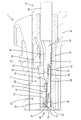
本実施例1のコネクタ1は、合成樹脂製の誘電体10と、一対(複数)の内導体36と、合成樹脂製のハウジング44とを備えて構成されている。誘電体10は、内部に左右一対の導体収容室17が形成された本体部材11と、本体部材11の前端部に組み付けられる前壁部材28とを備えて構成されている。本体部材11は、保持部材12と蓋部材24とを組み付けて構成されている。   The connector 1 according to the first embodiment includes a dielectric 10 made of synthetic resin, a pair (a plurality) of inner conductors 36, and a housing 44 made of synthetic resin. The dielectric 10 includes a main body member 11 having a pair of left and right conductor housing chambers 17 formed therein, and a front wall member 28 assembled to the front end portion of the main body member 11. The main body member 11 is configured by assembling the holding member 12 and the lid member 24.

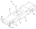
保持部材12は、図5,6に示すように、全体として前後方向に細長い形状をなしている。保持部材12は、前後方向に長い上壁部13と、上壁部13の左右両側縁からその全長に亘って略直角に下方へ延出した一対の側壁部14と、上壁部13の左右方向(幅方向)中央からその全長に亘って略直角に下方へ延出した隔壁部15とを備えている。   As shown in FIGS. 5 and 6, the holding member 12 has an elongated shape in the front-rear direction as a whole. The holding member 12 includes an upper wall portion 13 that is long in the front-rear direction, a pair of side wall portions 14 that extend downward at substantially right angles from the left and right side edges of the upper wall portion 13, and the left and right sides of the upper wall portion 13. And a partition wall 15 extending downward at a substantially right angle from the center in the direction (width direction).

保持部材12のうち上壁部13と一対の側壁部14とで囲まれた空間は、隔壁部15により左右に区画された一対の溝部16となっている。各溝部16は、導体収容室17を構成する。各溝部16は、前後方向に細長く、その全長に亘って保持部材12の下面に開放されている。各溝部16の内上面には抜止め凹部18が形成されている。溝部16の前端は保持部材12の前面に開放されている。溝部16の前端部には、上壁部13、側壁部14及び隔壁部15の一部を切欠した形態であり、且つ保持部材12の前端面に開放された逃がし凹部19が形成されている。溝部16の後端は保持部材12の後面に開放されている。   A space surrounded by the upper wall portion 13 and the pair of side wall portions 14 in the holding member 12 is a pair of groove portions 16 that are partitioned by a partition wall portion 15 on the left and right sides. Each groove portion 16 constitutes a conductor housing chamber 17. Each groove portion 16 is elongated in the front-rear direction, and is open to the lower surface of the holding member 12 over its entire length. A retaining recess 18 is formed on the inner upper surface of each groove 16. The front end of the groove 16 is open to the front surface of the holding member 12. In the front end portion of the groove portion 16, a part of the upper wall portion 13, the side wall portion 14, and the partition wall portion 15 is notched, and an escape recess 19 that is opened on the front end surface of the holding member 12 is formed. The rear end of the groove 16 is open to the rear surface of the holding member 12.

保持部材12の前端面のうち左右両側壁部14の前端面には、夫々、上下に間隔を空けた一対ずつの嵌合孔20が形成されている。左右両側壁部14の外側面の前端部には、一対の前側ロック突起21Fが形成され、左右両側壁部14の外側面の後端部には、一対の後側ロック突起21Rが形成されている。また、左右両側壁部14の外面には、夫々、前側ロック突起21Fと後側ロック突起21Rとの間に配された位置決め凹部22が形成されている。上壁部13の外面(上面)には、係止突起23が形成されている。   A pair of fitting holes 20 are formed on the front end surfaces of the left and right side wall portions 14 of the front end surface of the holding member 12 so as to be spaced apart from each other. A pair of front locking projections 21F are formed at the front end portions of the outer side surfaces of the left and right side wall portions 14, and a pair of rear locking projections 21R are formed at the rear end portions of the outer side surfaces of the left and right side wall portions 14. Yes. In addition, positioning recesses 22 are formed on the outer surfaces of the left and right side wall portions 14 so as to be disposed between the front lock projection 21F and the rear lock projection 21R, respectively. A locking projection 23 is formed on the outer surface (upper surface) of the upper wall portion 13.

蓋部材24は、図7に示すように、前後方向に細長い形状をなす。蓋部材24は、前後方向に長い下壁部25と、下壁部25の左右両側縁の前端部から上方へ略直角に延出した一対の前側弾性ロック片26Fと、下壁部25の左右両側縁の後端部から上方へ略直角に延出した一対の後側弾性ロック片26Rとを有する単一部品である。下壁部25の左右両側縁には、前側弾性ロック片26Fと後側弾性ロック片26Rとの間に配された左右一対の位置決め突部27が形成されている。   As shown in FIG. 7, the lid member 24 has an elongated shape in the front-rear direction. The lid member 24 includes a lower wall portion 25 that is long in the front-rear direction, a pair of front elastic lock pieces 26 </ b> F extending substantially perpendicularly from the front end portions of the left and right side edges of the lower wall portion 25, and left and right sides of the lower wall portion 25. This is a single part having a pair of rear elastic lock pieces 26R extending substantially perpendicularly upward from the rear ends of both side edges. A pair of left and right positioning projections 27 disposed between the front elastic lock piece 26F and the rear elastic lock piece 26R are formed on the left and right side edges of the lower wall portion 25.

蓋部材24は、保持部材12に対しその下面(溝部16がその前端から後端に至る全長領域に亘って開放されている面)を塞いだ状態で組み付けられている。組付け状態では、下壁部25が左右両側壁部14の下端面と隔壁部15の下端面に当接することにより、保持部材12と蓋部材24が上下方向に位置決めされる。また、前側ロック突起21Fと前側弾性ロック片26Fが係止し、後側ロック突起21Rと後側弾性ロック片26Rが係止することにより、保持部材12と蓋部材24が、上下方向への離間と左右方向への相対変位を規制される。さらに、位置決め凹部22と位置決め突部27が嵌合することにより、保持部材12と蓋部材24の前後方向への相対変位が規制されている。   The lid member 24 is assembled to the holding member 12 in a state where the lower surface (the surface where the groove 16 is opened over the entire length region from the front end to the rear end) is closed. In the assembled state, the lower wall portion 25 contacts the lower end surfaces of the left and right side wall portions 14 and the lower end surface of the partition wall portion 15, whereby the holding member 12 and the lid member 24 are positioned in the vertical direction. Further, the front lock protrusion 21F and the front elastic lock piece 26F are engaged, and the rear lock protrusion 21R and the rear elastic lock piece 26R are engaged, whereby the holding member 12 and the lid member 24 are separated in the vertical direction. And the relative displacement in the left-right direction is restricted. Furthermore, the relative displacement in the front-rear direction of the holding member 12 and the lid member 24 is restricted by the positioning recess 22 and the positioning projection 27 being fitted.

以上により、保持部材12と蓋部材24が上下に合体して取り付けられた状態に保持されている。保持部材12と蓋部材24が合体することにより、本体部材11が構成されている本体部材11の内部には、溝部16と下板部とにより導体収容室17が形成されている。換言すると、各導体収容室17は、上壁部13と一方の側壁部14と隔壁部15と下壁部25とによって囲まれた空間である。また、一対の導体収容室17は、隔壁部15によって絶縁状態に区画されている。導体収容室17の前端は本体部材11の前面に開放され、導体収容室17の後端は本体部材11の後面に開放されている。   As described above, the holding member 12 and the lid member 24 are held in a state where they are combined with each other vertically. By combining the holding member 12 and the lid member 24, the conductor housing chamber 17 is formed by the groove portion 16 and the lower plate portion inside the main body member 11 constituting the main body member 11. In other words, each conductor housing chamber 17 is a space surrounded by the upper wall portion 13, one side wall portion 14, the partition wall portion 15, and the lower wall portion 25. Further, the pair of conductor housing chambers 17 are partitioned in an insulating state by the partition wall portion 15. The front end of the conductor housing chamber 17 is open to the front surface of the main body member 11, and the rear end of the conductor housing chamber 17 is open to the rear surface of the main body member 11.

前壁部材28は、壁本体部29と、壁本体部29の後面から後方へ突出した左右一対の位置決め部30とを有する単一部品である。壁本体部29の後面における左右両端部には、夫々、後方へ片持ち状に突出した形態の上下一対ずつの嵌合突起31が形成されている。各嵌合突起31の突出端部(後端部)には、拡径部32が形成されている。   The front wall member 28 is a single part having a wall main body portion 29 and a pair of left and right positioning portions 30 protruding rearward from the rear surface of the wall main body portion 29. A pair of upper and lower fitting protrusions 31 are formed on the left and right ends of the rear surface of the wall body 29 so as to protrude rearward in a cantilevered manner. An enlarged diameter portion 32 is formed at the protruding end portion (rear end portion) of each fitting protrusion 31.

壁本体部29には、開口形状が方形をなす左右一対のタブ挿入口33が前後方向(壁本体部29の壁厚方向)に貫通した形態である。タブ挿入口33には、相手側内導体46の先端の細長いタブ47が挿通されるようになっている。壁本体部29の前面には、左右一対の誘導面34が形成されている。各誘導面34は、壁本体部29の前面のうち各タブ挿入口33の孔縁部に沿った方形枠状領域を、テーパ状に凹ませた形態である。タブ47が誘導面34に当接すると、誘導面34の傾斜によりタブ47がタブ挿入口33へ誘導されるようになっている。   The wall main body 29 has a form in which a pair of left and right tab insertion openings 33 having a square opening shape penetrate in the front-rear direction (the wall thickness direction of the wall main body 29). An elongated tab 47 at the tip of the mating inner conductor 46 is inserted into the tab insertion port 33. A pair of left and right guide surfaces 34 are formed on the front surface of the wall main body 29. Each guide surface 34 has a shape in which a rectangular frame-shaped region along the hole edge portion of each tab insertion port 33 in the front surface of the wall main body portion 29 is tapered. When the tab 47 abuts on the guide surface 34, the tab 47 is guided to the tab insertion port 33 due to the inclination of the guide surface 34.

各位置決め部30は、壁本体部29の後面から後方へ片持ち状に延出した角筒形状をなす。位置決め部30の背面視形状は、図9に示すように、全体として方形であり、上端部における右側部分には、上方へ凹ませた形態の誤嵌合規制凹部35が形成されている。各位置決め部30の前端部には、タブ挿入口33が開口している。位置決め部30の内部は後方へ開放された空間となっている。   Each positioning portion 30 has a rectangular tube shape extending in a cantilevered manner from the rear surface of the wall main body portion 29 to the rear. As shown in FIG. 9, the rear-view shape of the positioning portion 30 is a square as a whole, and an erroneous fitting restricting concave portion 35 is formed on the right side portion of the upper end portion so as to be recessed upward. A tab insertion port 33 is opened at the front end of each positioning portion 30. The interior of the positioning unit 30 is a space opened rearward.

前壁部材28は本体部材11の前端面に取り付けられている。前壁部材28を本体部材11に組み付けることで、誘電体10が構成されている。前壁部材28と本体部材11は、嵌合突起31を嵌合孔20に圧入し、嵌合突起31の先端の拡径部32を嵌合孔20の後面側の孔縁部に係止させることで、組付け状態にロックされている。   The front wall member 28 is attached to the front end surface of the main body member 11. The dielectric 10 is configured by assembling the front wall member 28 to the main body member 11. The front wall member 28 and the main body member 11 press-fit the fitting protrusion 31 into the fitting hole 20 and lock the enlarged diameter portion 32 at the tip of the fitting protrusion 31 to the hole edge on the rear surface side of the fitting hole 20. Thus, it is locked in the assembled state.

内導体36は、金属板材に曲げ加工等を施して成形されたものであり、全体として前後方向に細長い形状である。内導体36の前端側領域には角筒状の導体本体部37が形成され、内導体36の後端側領域にはオープンバレル状の圧着部38が形成されている。導体本体部37の前端部には、その上面から上方へ突出したスタビライザ39(図2を参照)が形成されている。導体本体部37の後端部には、その上面から上方へ突出した形態の抜止め突起40が形成されている。   The inner conductor 36 is formed by bending a metal plate material or the like, and has an elongated shape in the front-rear direction as a whole. A rectangular tube-shaped conductor main body 37 is formed in the front end side region of the inner conductor 36, and an open barrel-shaped crimping portion 38 is formed in the rear end side region of the inner conductor 36. A stabilizer 39 (see FIG. 2) is formed at the front end portion of the conductor main body portion 37 so as to protrude upward from the upper surface thereof. At the rear end portion of the conductor main body portion 37, a retaining projection 40 is formed that protrudes upward from the upper surface thereof.

2つの内導体36には、2本の電線42の前端部が、個別に且つ導通可能に接続されている。詳細には、各圧着部38には、夫々、電線42の前端部が、導通可能に且つ概ね同軸状に圧着されている。2本の電線42は、互いに螺旋状に撚り合わせることでツイストペア線41を構成するものである。ツイストペア線41は、筒状の絶縁部材43により一括して包囲された状態で一体化されており、信号回路を構成している。   The two inner conductors 36 are connected to the front end portions of the two electric wires 42 individually and in a conductive manner. Specifically, the front end portion of the electric wire 42 is crimped to each crimping portion 38 so as to be conductive and substantially coaxial. The two electric wires 42 constitute a twisted pair wire 41 by being twisted together in a spiral shape. The twisted pair wire 41 is integrated in a state of being collectively surrounded by a cylindrical insulating member 43 and constitutes a signal circuit.

内導体36の前端部は、前壁部材28の後方から各位置決め部30の内部に嵌合されている。位置決め部30に嵌合された内導体36は、前壁部材28に対し上下方向及び左右方向への相対変位を規制された状態で位置決めされている。また、スタビライザ39が誤嵌合規制凹部35に収容されている。   A front end portion of the inner conductor 36 is fitted into each positioning portion 30 from the rear of the front wall member 28. The inner conductor 36 fitted to the positioning portion 30 is positioned with respect to the front wall member 28 in a state where relative displacement in the vertical direction and the horizontal direction is restricted. Further, the stabilizer 39 is accommodated in the erroneous fitting restricting recess 35.

したがって、内導体36を位置決め部30に対し上下反転した向きで嵌合しようとすると、スタビライザ39が位置決め部30の下端部の後端縁と干渉するので、位置決め部30(前壁部材28)に対して内導体36が上下反転した不正な向きで嵌合されることが防止されている。   Therefore, if the inner conductor 36 is to be fitted to the positioning portion 30 in an upside down orientation, the stabilizer 39 interferes with the rear end edge of the lower end portion of the positioning portion 30, so that the positioning portion 30 (front wall member 28) On the other hand, it is possible to prevent the inner conductor 36 from being fitted in an incorrect direction that is upside down.

各内導体36は、夫々、導体収容室17内に収容されている。導体収容室17に収容された内導体36は、上壁部13、下壁部25、側壁部14及び隔壁部15に当接することにより、導体収容室17(誘電体10)に対して上下方向及び左右方向への相対変位を規制された状態に保持されている。また、抜止め突起40と抜止め凹部18との嵌合により、内導体36は、導体収容室17(誘電体10)に対し前後方向への相対変位を規制された状態に保持されている。   Each inner conductor 36 is accommodated in the conductor accommodating chamber 17. The inner conductor 36 accommodated in the conductor accommodating chamber 17 contacts the upper wall portion 13, the lower wall portion 25, the side wall portion 14, and the partition wall portion 15, thereby moving up and down with respect to the conductor accommodating chamber 17 (dielectric 10). And the relative displacement to the left-right direction is hold | maintained at the controlled state. Further, the inner conductor 36 is held in a state in which relative displacement in the front-rear direction with respect to the conductor housing chamber 17 (dielectric 10) is restricted by the fitting between the retaining protrusion 40 and the retaining recess 18.

誘電体10は、保持部材12と蓋部材24と前壁部材28の3つの部品を組み付けて構成されている。保持部材12の材料、材質は、ポリプロピレン(PP)が用いられている。また、蓋部材24の材料、材質もポリプロピレンである。つまり、本体部材11を構成する保持部材12と蓋部材24は、同一の材料、材質からなる。一方、誘電体10の前面部を構成する前壁部材28の材料、材質は、比較的機械的強度の高い合成樹脂であるポリブチレンテレフタレート(PBT)が用いられている。   The dielectric 10 is configured by assembling three parts, that is, a holding member 12, a lid member 24, and a front wall member 28. The material of the holding member 12 is made of polypropylene (PP). The material and material of the lid member 24 are also polypropylene. That is, the holding member 12 and the lid member 24 constituting the main body member 11 are made of the same material. On the other hand, polybutylene terephthalate (PBT), which is a synthetic resin having a relatively high mechanical strength, is used for the material and the material of the front wall member 28 constituting the front surface portion of the dielectric 10.

本体部材11の材料であるポリブチレンテレフタレートは、ポリプロピレンに比べて機械的強度が高く、誘電率(比誘電率)も高い。本体部材11の材料、材質選定に際しては、内導体36が信号回路を構成するものであり、保持部材12には2つの内導体36を仕切る隔壁部15が一体形成されていることが考慮されている。これにより、本体部材11の材料。材質として、信号伝達への影響の少ない合成樹脂、即ち比較的誘電率(比誘電率)の低いポリプロピレンが選択されている。   Polybutylene terephthalate, which is the material of the main body member 11, has higher mechanical strength and higher dielectric constant (relative dielectric constant) than polypropylene. When selecting the material and material of the main body member 11, it is considered that the inner conductor 36 constitutes a signal circuit, and the partition member 15 that partitions the two inner conductors 36 is integrally formed on the holding member 12. Yes. Thereby, the material of the main body member 11. As a material, a synthetic resin having a small influence on signal transmission, that is, a polypropylene having a relatively low dielectric constant (relative dielectric constant) is selected.

一方、前壁部材28の材料、材質選定に際しては、誘電体10の前方から相手側内導体46の細長いタブ47がタブ挿入口33に挿入されるようになっているため、タブ47が、公差の影響等により前壁部材28の前面の誘導面34に突き刺さる懸念が考慮されている。これにより、前壁部材28の材料として、タブ47が突き刺さらない程度の機械的強度を有するポリブチレンテレフタレートが選択されている。   On the other hand, when selecting the material and material of the front wall member 28, since the elongated tab 47 of the mating inner conductor 46 is inserted into the tab insertion port 33 from the front of the dielectric 10, the tab 47 has a tolerance. The concern of piercing the front guide surface 34 of the front wall member 28 due to the influence of the above is taken into consideration. As a result, polybutylene terephthalate having a mechanical strength that does not pierce the tab 47 is selected as the material of the front wall member 28.

次に、本実施例1のコネクタ1の組付け手順を説明する。各内導体36の後端部には電線42の前端部が圧着される。電線42が圧着済みの2つの内導体36は、前壁部材28の左右一対の位置決め部30に個別に嵌合され、これにより、前壁部材28に対して上下方向及び左右方向に位置決めされる。この後、前壁部材28と2つの内導体36を、上下反転させた保持部材12にセットする。   Next, a procedure for assembling the connector 1 according to the first embodiment will be described. The front end portion of the electric wire 42 is crimped to the rear end portion of each inner conductor 36. The two inner conductors 36 to which the electric wires 42 have been crimped are individually fitted into the pair of left and right positioning portions 30 of the front wall member 28, thereby being positioned in the vertical direction and the horizontal direction with respect to the front wall member 28. . Thereafter, the front wall member 28 and the two inner conductors 36 are set on the holding member 12 that is turned upside down.

このとき、前壁部材28を正規の取付け位置よりも少し前方に位置させた状態で、各内導体36を溝部16に収容する。このときの溝部16に対する内導体36の取付け方向は、内導体36及び電線42の軸線方向(前後方向)に対してほぼ直角に交差する方向なので、2本の電線42の前端部のうち絶縁部材43の前端から露出させて撚りを解く領域の長さは、後方から溝部16(導体収容室17)に内導体36を挿入する場合に比べると、短くて済む。したがって、ツイストペア線41としての電磁シールド機能に優れている。   At this time, each inner conductor 36 is accommodated in the groove portion 16 in a state where the front wall member 28 is positioned slightly ahead of the regular attachment position. At this time, the mounting direction of the inner conductor 36 with respect to the groove portion 16 is a direction that intersects at almost right angles to the axial direction (front-rear direction) of the inner conductor 36 and the electric wire 42, so that the insulating member of the front end portions of the two electric wires 42 The length of the region that is exposed from the front end of 43 and untwisted is shorter than that in the case where the inner conductor 36 is inserted into the groove portion 16 (conductor accommodating chamber 17) from the rear. Accordingly, the electromagnetic shield function as the twisted pair wire 41 is excellent.

前壁部材28と内導体36を一体的に保持部材12にセットした状態では、壁本体部29が保持部材12の前方に離間しているので、内導体36の位置も正規の取付け位置より前方にずれている。したがって、この位置ずれを矯正するために、前壁部材28と一緒に内導体36を後方へ移動させ、壁本体部29の後面を保持部材12の前面に当接させる。このとき、前壁部材28の嵌合突起31を保持部材12の嵌合孔20に圧入し、嵌合突起31の拡径部32を保持部材12に係止させる。以上により、前壁部材28が保持部材12に対し正規の形態で組み付けられるとともに、内導体36が溝部16内の正規位置に収容される。   In a state where the front wall member 28 and the inner conductor 36 are integrally set on the holding member 12, the wall main body 29 is separated from the front of the holding member 12, so that the position of the inner conductor 36 is also more forward than the normal mounting position. It is shifted to. Therefore, in order to correct this misalignment, the inner conductor 36 is moved rearward together with the front wall member 28, and the rear surface of the wall main body 29 is brought into contact with the front surface of the holding member 12. At this time, the fitting protrusion 31 of the front wall member 28 is press-fitted into the fitting hole 20 of the holding member 12, and the enlarged diameter portion 32 of the fitting protrusion 31 is locked to the holding member 12. As described above, the front wall member 28 is assembled to the holding member 12 in a regular form, and the inner conductor 36 is accommodated in the regular position in the groove 16.

内導体36が適正に溝部16に収容された状態では、抜止め突起40が抜止め凹部18に係止することにより、内導体36は保持部材12(溝部16)に対して前後方向への相対変位を規制された状態に保持される。また、位置決め部30は、保持部材12の逃がし凹部19に嵌合される。以上により、前壁部材28と2つの内導体36が保持部材12に対して一体化される。   In a state where the inner conductor 36 is properly accommodated in the groove portion 16, the retaining protrusion 40 is engaged with the retaining recess 18, so that the inner conductor 36 is relative to the holding member 12 (groove portion 16) in the front-rear direction. The displacement is held in a regulated state. Further, the positioning portion 30 is fitted into the relief recess 19 of the holding member 12. As described above, the front wall member 28 and the two inner conductors 36 are integrated with the holding member 12.

この後、保持部材12に対し蓋部材24を上下に接近させるようにして合体させる。保持部材12と蓋部材24を合体した状態では、前側弾性ロック片26Fと前側ロック突起21Fが係止し、後側弾性ロック片26Rと後側ロック突起21Rが係止し、位置決め凹部22と位置決め突部27が係止することにより、保持部材12と蓋部材24が合体状態に保持される。以上により、誘電体10の組付けが完了すると同時に、誘電体10内に2つの内導体36が収容された状態となる。内導体36が取り付けられた誘電体10は、ハウジング44内に挿入され、ランス45と係止突起23との係止により抜止め状態にロックされる。   Thereafter, the lid member 24 is combined with the holding member 12 so as to approach each other. In the state where the holding member 12 and the lid member 24 are combined, the front elastic lock piece 26F and the front lock protrusion 21F are engaged, the rear elastic lock piece 26R and the rear lock protrusion 21R are engaged, and the positioning recess 22 and the positioning member 22 are positioned. When the protrusion 27 is locked, the holding member 12 and the lid member 24 are held in the combined state. As a result, the assembly of the dielectric 10 is completed, and at the same time, the two inner conductors 36 are accommodated in the dielectric 10. The dielectric 10 to which the inner conductor 36 is attached is inserted into the housing 44, and is locked in a retaining state by the locking of the lance 45 and the locking projection 23.

本実施例1のコネクタ1は、通信性能の向上と嵌合動作の信頼性向上とを両立させることを目的とするものであり、誘電体10と2つ(複数)の内導体36とを備えている。誘電体10は、隔壁部15によって左右に区画された2つの導体収容室17を有し、2つの導体収容室17には2つの内導体36が個別に収容されている。   The connector 1 of the first embodiment is intended to achieve both improvement in communication performance and improvement in reliability of fitting operation, and includes a dielectric 10 and two (a plurality of) inner conductors 36. ing. The dielectric body 10 has two conductor housing chambers 17 which are divided on the left and right by the partition wall portion 15, and two inner conductors 36 are individually housed in the two conductor housing chambers 17.

誘電体10は、隔壁部15と2つの導体収容室17とが形成された合成樹脂製の本体部材11と、導体収容室17の前端の開口を塞ぐように本体部材11の前端部に取り付けられた合成樹脂製の前壁部材28とを備えて構成されている。前壁部材28には、誘電体10の前方から相手側内導体46のタブ47を導体収容室17内に挿入させることを許容するタブ挿入口33が形成されている。   The dielectric 10 is attached to the front end of the main body member 11 so as to close the opening of the front end of the conductor housing chamber 17 and the synthetic resin main body member 11 in which the partition wall portion 15 and the two conductor housing chambers 17 are formed. And a front wall member 28 made of synthetic resin. The front wall member 28 is formed with a tab insertion port 33 that allows the tab 47 of the counterpart inner conductor 46 to be inserted into the conductor housing chamber 17 from the front of the dielectric 10.

隔壁部15の材料、材質は、前壁部材28より誘電率の低い合成樹脂材料(ポリプロピレン)からなる。前壁部材28の材料、材質は、隔壁部15より機械的強度の高いもの(ポリブチレンテレフタレート)からなる。本実施例1のコネクタ1では、2つの内導体36の間に介在する隔壁部15の材料、材質を、比較的誘電率の低い材料、材質としたので、内導体36を通る電気信号の通信性能が保証される。また、前壁部材28の材料、材質は、隔壁部15に比べて機械的強度の高い材料、材質であるから、相手側内導体46のタブ47が前壁部材28と干渉しても、タブ47が前壁部材28に突き刺さる虞はない。   The material of the partition wall 15 is made of a synthetic resin material (polypropylene) having a dielectric constant lower than that of the front wall member 28. The material of the front wall member 28 is made of a material (polybutylene terephthalate) having higher mechanical strength than the partition wall portion 15. In the connector 1 according to the first embodiment, since the material and material of the partition wall 15 interposed between the two inner conductors 36 are materials and materials having a relatively low dielectric constant, electrical signal communication through the inner conductor 36 is performed. Performance is guaranteed. Further, since the material and material of the front wall member 28 are materials and materials having higher mechanical strength than the partition wall portion 15, even if the tab 47 of the mating inner conductor 46 interferes with the front wall member 28, the tab There is no possibility that 47 will pierce the front wall member 28.

また、内導体36の後端部に接続した2本の電線42は、ツイストペア線41を構成するものである。そのため、各電線42に接続した内導体36を、本体部材11の後方から導体収容室17に挿入する場合には、電線42の撚りを解く長さを長くする必要がある。この点に鑑み、本実施例1では、誘電体10を、保持部材12と蓋部材24とに分割した形態とし、保持部材12には、隔壁部15と、2つの導体収容室17を構成する2つの溝部16とを形成した。そして、蓋部材24は、2つの溝部16の開口部を閉塞するように保持部材12に取り付けた。この構成によれば、2つの内導体36を誘電体10の後方から導体収容室17に挿入する必要がないので、電線42の撚りを解く長さを短縮することができ、ひいては、ツイストペア線41のシールド機能の信頼性低下を回避できる。   Further, the two electric wires 42 connected to the rear end portion of the inner conductor 36 constitute a twisted pair wire 41. Therefore, when the inner conductor 36 connected to each electric wire 42 is inserted into the conductor housing chamber 17 from the back of the main body member 11, it is necessary to increase the length for untwisting the electric wire 42. In view of this point, in the first embodiment, the dielectric 10 is divided into a holding member 12 and a lid member 24, and the holding member 12 includes a partition wall portion 15 and two conductor housing chambers 17. Two groove portions 16 were formed. The lid member 24 was attached to the holding member 12 so as to close the openings of the two groove portions 16. According to this configuration, since it is not necessary to insert the two inner conductors 36 into the conductor accommodating chamber 17 from the rear side of the dielectric body 10, the length for untwisting the electric wire 42 can be shortened, and as a result, the twisted pair wire 41 It is possible to avoid a decrease in reliability of the shield function.

また、前壁部材28には、2つの内導体36の前端部を位置決め可能な位置決め部30が形成されている。この構成によれば、2つの内導体36を位置決め部30で位置決めした状態で前壁部と一体化させることにより、2つの内導体36を2つの溝部16にワンアクションで収容することができる。   The front wall member 28 is formed with a positioning portion 30 that can position the front end portions of the two inner conductors 36. According to this configuration, the two inner conductors 36 can be accommodated in the two groove portions 16 in one action by integrating the two inner conductors 36 with the front wall portion while being positioned by the positioning portion 30.

<実施例2>
以下、本発明を具体化した実施例2を図11〜図21を参照して説明する。尚、以下の説明において、前後の方向については、図12〜17における左方を前方と定義する。上下の方向については、図11,12,14,16,18〜20にあらわれる向きを、そのまま上方、下方と定義する。
<Example 2>
A second embodiment embodying the present invention will be described below with reference to FIGS. In the following description, with respect to the front-rear direction, the left side in FIGS. For the up and down directions, the directions appearing in FIGS. 11, 12, 14, 16, and 18 to 20 are defined as upper and lower as they are.

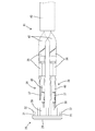
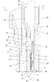
本実施例2のコネクタ2は、合成樹脂製の誘電体50と、一対(複数)の内導体76と、合成樹脂製のハウジング85とを備えて構成されている。誘電体50は、内部に左右一対の導体収容室57が形成された本体部材51と、本体部材51の前端部に組み付けられる前壁部材69とを備えて構成されている。本体部材51は、保持部材52と蓋部材64とを組み付けて構成されている。   The connector 2 of the second embodiment includes a synthetic resin dielectric 50, a pair (a plurality) of inner conductors 76, and a synthetic resin housing 85. The dielectric 50 includes a main body member 51 having a pair of left and right conductor housing chambers 57 formed therein, and a front wall member 69 assembled to the front end portion of the main body member 51. The main body member 51 is configured by assembling a holding member 52 and a lid member 64.

保持部材52は、図14,15に示すように、全体として前後方向に細長い形状をなしている。保持部材52は、前後方向に長い上壁部53と、上壁部53の左右両側縁からその全長に亘って略直角に下方へ延出した一対の側壁部54と、上壁部53の左右方向(幅方向)中央からその全長に亘って略直角に下方へ延出した隔壁部55とを備えている。   As shown in FIGS. 14 and 15, the holding member 52 has an elongated shape in the front-rear direction as a whole. The holding member 52 includes an upper wall portion 53 that is long in the front-rear direction, a pair of side wall portions 54 that extend downward at substantially right angles from the left and right side edges of the upper wall portion 53, and the left and right sides of the upper wall portion 53. And a partition wall 55 extending downward at a substantially right angle from the center in the direction (width direction).

保持部材52のうち上壁部53と一対の側壁部54とで囲まれた空間は、隔壁部55により左右に区画された一対の溝部56となっている。各溝部56は、導体収容室57を構成する。各溝部56は、前後方向に細長く、その全長に亘って保持部材52の下面に開放されている。各溝部56の内上面には抜止め凹部58が形成されている。溝部56の前端は保持部材52の前面に開放されている。溝部56の後端は保持部材52の後面に開放されている。   A space surrounded by the upper wall portion 53 and the pair of side wall portions 54 of the holding member 52 is a pair of groove portions 56 that are partitioned on the left and right by the partition wall portion 55. Each groove portion 56 constitutes a conductor housing chamber 57. Each groove portion 56 is elongated in the front-rear direction, and is open to the lower surface of the holding member 52 over its entire length. A retaining recess 58 is formed on the inner upper surface of each groove 56. The front end of the groove 56 is open to the front surface of the holding member 52. The rear end of the groove 56 is open to the rear surface of the holding member 52.

保持部材52の前端面のうち左右両側壁部54の前端面には、夫々、上下に間隔を空けた一対ずつの嵌合孔60(請求項に記載の嵌合部)が形成されている。左右両側壁部54の外側面の前端部には、一対の前側ロック突起61Fが形成され、左右両側壁部54の外側面の後端部には、一対の後側ロック突起61Rが形成されている。また、左右両側壁部54の外面には、夫々、前側ロック突起61Fと後側ロック突起61Rとの間に配された位置決め凹部62が形成されている。上壁部53の外面(上面)には、係止突起63が形成されている。   A pair of fitting holes 60 (fitting portions described in claims) are formed on the front end surfaces of the left and right side wall portions 54 of the front end surface of the holding member 52, respectively. A pair of front locking projections 61F are formed at the front end portions of the outer side surfaces of the left and right side wall portions 54, and a pair of rear locking projections 61R are formed at the rear end portions of the outer side surfaces of the left and right side wall portions 54. Yes. In addition, positioning recesses 62 are formed on the outer surfaces of the left and right side wall portions 54 so as to be disposed between the front lock projection 61F and the rear lock projection 61R, respectively. A locking projection 63 is formed on the outer surface (upper surface) of the upper wall portion 53.

蓋部材64は、図16,17に示すように、前後方向に細長い形状をなす。蓋部材64は、前後方向に長い下壁部65と、下壁部65の左右両側縁の前端部から上方へ略直角に延出した一対の前側弾性ロック片66Fと、下壁部65の左右両側縁の後端部から上方へ略直角に延出した一対の後側弾性ロック片66Rとを有する単一部品である。下壁部65の左右両側縁には、前側弾性ロック片66Fと後側弾性ロック片66Rとの間に配された左右一対の位置決め突部67が形成されている。下壁部65の前端部外面(下面)には、左右方向中央部を浅く凹ませた形態の受圧部68が形成されている。   As shown in FIGS. 16 and 17, the lid member 64 has an elongated shape in the front-rear direction. The lid member 64 includes a lower wall portion 65 that is long in the front-rear direction, a pair of front elastic locking pieces 66F that extend upward at substantially right angles from the front end portions of the left and right side edges of the lower wall portion 65, and the left and right sides of the lower wall portion 65. This is a single part having a pair of rear elastic locking pieces 66R extending substantially perpendicularly upward from the rear ends of both side edges. A pair of left and right positioning projections 67 disposed between the front elastic lock piece 66F and the rear elastic lock piece 66R are formed on the left and right side edges of the lower wall portion 65. On the outer surface (lower surface) of the front end portion of the lower wall portion 65, a pressure receiving portion 68 having a shape in which a central portion in the left-right direction is recessed shallowly is formed.

蓋部材64は、保持部材52に対しその下面(溝部56がその前端から後端に至る全長領域に亘って開放されている面)を塞いだ状態で組み付けられている。組付け状態では、下壁部65が左右両側壁部54の下端面と隔壁部55の下端面に当接することにより、保持部材52と蓋部材64が上下方向に位置決めされる。また、前側ロック突起61Fと前側弾性ロック片66Fが係止し、後側ロック突起61Rと後側弾性ロック片66Rが係止することにより、保持部材52と蓋部材64が、上下方向への離間と左右方向への相対変位を規制される。さらに、位置決め凹部62と位置決め突部67が嵌合することにより、保持部材52と蓋部材64の前後方向への相対変位が規制されている。   The lid member 64 is assembled to the holding member 52 in a state where the lower surface (the surface where the groove portion 56 is opened over the entire length region from the front end to the rear end) is closed. In the assembled state, the lower wall portion 65 contacts the lower end surfaces of the left and right side wall portions 54 and the lower end surface of the partition wall portion 55, whereby the holding member 52 and the lid member 64 are positioned in the vertical direction. Further, the front lock protrusion 61F and the front elastic lock piece 66F are engaged, and the rear lock protrusion 61R and the rear elastic lock piece 66R are engaged, so that the holding member 52 and the lid member 64 are separated in the vertical direction. And the relative displacement in the left-right direction is restricted. Furthermore, the relative displacement of the holding member 52 and the lid member 64 in the front-rear direction is restricted by fitting the positioning recess 62 and the positioning projection 67.

以上により、保持部材52と蓋部材64が上下に合体して取り付けられた状態に保持されている。保持部材52と蓋部材64が合体することにより、本体部材51が構成されている本体部材51の内部には、溝部56と下板部とにより導体収容室57が形成されている。換言すると、各導体収容室57は、上壁部53と一方の側壁部54と隔壁部55と下壁部65とによって囲まれた空間である。また、一対の導体収容室57は、隔壁部55によって絶縁状態に区画されている。導体収容室57の前端は本体部材51の前面に開放され、導体収容室57の後端は本体部材51の後面に開放されている。   As described above, the holding member 52 and the lid member 64 are held in a state where they are combined and attached in the vertical direction. By combining the holding member 52 and the lid member 64, a conductor accommodating chamber 57 is formed by the groove portion 56 and the lower plate portion inside the main body member 51 constituting the main body member 51. In other words, each conductor housing chamber 57 is a space surrounded by the upper wall portion 53, one side wall portion 54, the partition wall portion 55, and the lower wall portion 65. Further, the pair of conductor accommodating chambers 57 are partitioned in an insulating state by the partition wall portion 55. The front end of the conductor housing chamber 57 is opened to the front surface of the main body member 51, and the rear end of the conductor housing chamber 57 is opened to the rear surface of the main body member 51.

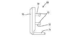
前壁部材69は、壁本体部70と、押さえ部71とを有する単一部品である。押さえ部71は、壁本体部70の下端縁部における左右方向中央部から後方へ略直角に片持ち状に延出した板状をなしている。壁本体部70の後面における左右両端部には、夫々、後方へ片持ち状に突出した形態の上下一対ずつの嵌合突起72(請求項に記載の嵌合部)が形成されている。各嵌合突起72の突出端部(後端部)には、拡径部73が形成されている。   The front wall member 69 is a single component having a wall main body portion 70 and a pressing portion 71. The pressing portion 71 has a plate shape that extends in a cantilevered manner at a substantially right angle from the central portion in the left-right direction at the lower end edge of the wall main body portion 70. A pair of upper and lower fitting projections 72 (fitting portions described in claims) are formed on both left and right ends of the rear surface of the wall main body portion 70 so as to protrude rearward in a cantilevered manner. An enlarged diameter portion 73 is formed at the protruding end portion (rear end portion) of each fitting protrusion 72.

壁本体部70には、開口形状が方形をなす左右一対のタブ挿入口74が前後方向(壁本体部70の壁厚方向)に貫通した形態である。タブ挿入口74には、相手側内導体83の先端の細長いタブ84が挿通されるようになっている。壁本体部70の前面には、左右一対の誘導面75が形成されている。各誘導面75は、壁本体部70の前面のうち各タブ挿入口74の孔縁部に沿った方形枠状領域を、テーパ状に凹ませた形態である。タブ84が誘導面75に当接すると、誘導面75の傾斜によりタブ84がタブ挿入口74へ誘導されるようになっている。   The wall body portion 70 has a pair of left and right tab insertion ports 74 whose opening shape forms a square shape penetrating in the front-rear direction (the wall thickness direction of the wall body portion 70). An elongated tab 84 at the tip of the mating inner conductor 83 is inserted into the tab insertion opening 74. A pair of left and right guide surfaces 75 are formed on the front surface of the wall main body 70. Each guide surface 75 has a shape in which a rectangular frame-shaped region along the hole edge of each tab insertion opening 74 in the front surface of the wall main body 70 is recessed. When the tab 84 abuts on the guide surface 75, the tab 84 is guided to the tab insertion port 74 due to the inclination of the guide surface 75.

前壁部材69は本体部材51の前端面に取り付けられている。前壁部材69を本体部材51に組み付けることで、誘電体50が構成されている。前壁部材69と本体部材51は、嵌合突起72を嵌合孔60に圧入し、嵌合突起72の先端の拡径部73を嵌合孔60の後面側の孔縁部に係止させることで、組付け状態にロックされている。   The front wall member 69 is attached to the front end surface of the main body member 51. The dielectric 50 is configured by assembling the front wall member 69 to the main body member 51. The front wall member 69 and the main body member 51 press-fit the fitting protrusion 72 into the fitting hole 60 and lock the enlarged diameter portion 73 at the tip of the fitting protrusion 72 to the hole edge on the rear surface side of the fitting hole 60. Thus, it is locked in the assembled state.

内導体76は、金属板材に曲げ加工等を施して成形されたものであり、全体として前後方向に細長い形状である。内導体76の前端側領域には角筒状の導体本体部77が形成され、内導体76の後端側領域にはオープンバレル状の圧着部78が形成されている。導体本体部77の後端部には、その上面から上方へ突出した形態の抜止め突起79が形成されている。   The inner conductor 76 is formed by bending a metal plate material or the like, and has an elongated shape in the front-rear direction as a whole. A rectangular tube-shaped conductor main body 77 is formed in the front end side region of the inner conductor 76, and an open barrel-shaped crimping portion 78 is formed in the rear end side region of the inner conductor 76. At the rear end portion of the conductor main body 77, a retaining projection 79 is formed so as to protrude upward from the upper surface thereof.

2つの内導体76には、2本の電線81の前端部が、個別に且つ導通可能に接続されている。詳細には、各圧着部78には、夫々、電線81の前端部が、導通可能に且つ概ね同軸状に圧着されている。2本の電線81は、互いに螺旋状に撚り合わせることでツイストペア線80を構成するものである。ツイストペア線80は、筒状の絶縁部材82により一括して包囲された状態で一体化されており、信号回路を構成している。   The front ends of the two electric wires 81 are individually and continually connected to the two inner conductors 76. Specifically, the front end portion of the electric wire 81 is crimped to each crimp portion 78 so as to be conductive and substantially coaxial. The two electric wires 81 constitute a twisted pair wire 80 by being twisted together in a spiral shape. The twisted pair wires 80 are integrated in a state of being collectively surrounded by a cylindrical insulating member 82, and constitute a signal circuit.

各内導体76は、夫々、導体収容室57内に収容されている。導体収容室57に収容された内導体76は、上壁部53、下壁部65、側壁部54及び隔壁部55に当接することにより、導体収容室57(誘電体50)に対して上下方向及び左右方向への相対変位を規制された状態に保持されている。また、抜止め突起79と抜止め凹部58との嵌合により、内導体76は、導体収容室57(誘電体50)に対し前後方向への相対変位を規制された状態に保持されている。   Each inner conductor 76 is housed in a conductor housing chamber 57. The inner conductor 76 accommodated in the conductor accommodating chamber 57 abuts on the upper wall portion 53, the lower wall portion 65, the side wall portion 54 and the partition wall portion 55, so that it is vertically directed with respect to the conductor accommodating chamber 57 (dielectric 50). And the relative displacement to the left-right direction is hold | maintained at the controlled state. Further, the inner conductor 76 is held in a state in which relative displacement in the front-rear direction with respect to the conductor housing chamber 57 (dielectric 50) is restricted by the fitting between the retaining protrusion 79 and the retaining recess 58.

誘電体50は、保持部材52と蓋部材64と前壁部材69の3つの部品を組み付けて構成されている。保持部材52の材料は、ポリプロピレン(PP)が用いられている。また、蓋部材64の材料もポリプロピレンである。つまり、本体部材51を構成する保持部材52と蓋部材64は、同一の材料からなる。一方、誘電体50の前面部を構成する前壁部材69の材料は、比較的機械的強度の高い合成樹脂であるポリブチレンテレフタレート(PBT)が用いられている。   The dielectric 50 is configured by assembling three parts, that is, a holding member 52, a lid member 64, and a front wall member 69. The material of the holding member 52 is polypropylene (PP). The material of the lid member 64 is also polypropylene. That is, the holding member 52 and the lid member 64 constituting the main body member 51 are made of the same material. On the other hand, polybutylene terephthalate (PBT), which is a synthetic resin having a relatively high mechanical strength, is used as the material of the front wall member 69 constituting the front surface portion of the dielectric 50.

本体部材51の材料であるポリブチレンテレフタレートは、ポリプロピレンに比べて機械的強度が高く、誘電率(比誘電率)も高い。本体部材51の材料、材質選定に際しては、内導体76が信号回路を構成するものであり、保持部材52には2つの内導体76を仕切る隔壁部55が一体形成されていることが考慮されている。これにより、本体部材51の材料、材質として、信号伝達への影響の少ない合成樹脂、即ち比較的誘電率(比誘電率)の低いポリプロピレンが選択されている。   Polybutylene terephthalate, which is the material of the main body member 51, has higher mechanical strength and higher dielectric constant (relative dielectric constant) than polypropylene. When selecting the material and material of the main body member 51, it is considered that the inner conductor 76 constitutes a signal circuit, and the holding member 52 is integrally formed with a partition wall portion 55 that partitions the two inner conductors 76. Yes. As a result, a synthetic resin that has little influence on signal transmission, that is, a polypropylene having a relatively low dielectric constant (relative dielectric constant) is selected as the material of the main body member 51.

一方、前壁部材69の材料、材質選定に際しては、誘電体50の前方から相手側内導体83の細長いタブ84がタブ挿入口74に挿入されるようになっているため、タブ84が、公差の影響等により前壁部材69の前面の誘導面75に突き刺さる懸念が考慮されている。これにより、前壁部材69の材料、材質として、タブ84が突き刺さらない程度の機械的強度を有するポリブチレンテレフタレートが選択されている。   On the other hand, when selecting the material and material of the front wall member 69, since the elongated tab 84 of the counterpart inner conductor 83 is inserted into the tab insertion port 74 from the front of the dielectric 50, the tab 84 has a tolerance. The concern of piercing the front guide surface 75 of the front wall member 69 due to the influence of the above is taken into consideration. As a result, polybutylene terephthalate having a mechanical strength such that the tab 84 does not pierce is selected as the material of the front wall member 69.

次に、本実施例2のコネクタ2の組付け手順を説明する。各内導体76の後端部には電線81の前端部が圧着される。電線81が圧着済みの2つの内導体76は、上下反転させた保持部材52にセットされ、2つの溝部56に個別に収容される。内導体76が適正に溝部56に収容された状態では、抜止め突起79が抜止め凹部58に係止することにより、内導体76は保持部材52(溝部56)に対して前後方向への相対変位を規制された状態に保持される。   Next, a procedure for assembling the connector 2 according to the second embodiment will be described. The front end portion of the electric wire 81 is crimped to the rear end portion of each inner conductor 76. The two inner conductors 76 to which the electric wires 81 have been crimped are set on the holding member 52 that is turned upside down and individually accommodated in the two groove portions 56. In a state where the inner conductor 76 is properly accommodated in the groove portion 56, the retaining protrusion 79 is engaged with the retaining recess 58, so that the inner conductor 76 is relative to the holding member 52 (groove portion 56) in the front-rear direction. The displacement is held in a regulated state.

また、溝部56に対する内導体76の取付け方向は、内導体76及び電線81の軸線方向(前後方向)に対してほぼ直角に交差する方向なので、2本の電線81の前端部のうち絶縁部材82の前端から露出させて撚りを解く領域の長さは、後方から溝部56(導体収容室57)に内導体76を挿入する場合に比べると、短くて済む。したがって、ツイストペア線80としての電磁シールド機能に優れている。   In addition, since the mounting direction of the inner conductor 76 with respect to the groove portion 56 is a direction that intersects at almost right angles to the axial direction (front-rear direction) of the inner conductor 76 and the electric wire 81, the insulating member 82 among the front end portions of the two electric wires 81. The length of the region that is exposed from the front end of the wire and untwisted is shorter than when the inner conductor 76 is inserted into the groove 56 (conductor accommodating chamber 57) from the rear. Therefore, the electromagnetic shield function as the twisted pair wire 80 is excellent.

この後、保持部材52に対し蓋部材64を上下に接近させるようにして合体させる。保持部材52と蓋部材64を合体した状態では、前側弾性ロック片66Fと前側ロック突起61Fが係止し、後側弾性ロック片66Rと後側ロック突起61Rが係止し、位置決め凹部62と位置決め突部67が係止することにより、保持部材52と蓋部材64が合体状態に保持される。合体状態では、2つの内導体76が、導体収容室57内に収容された状態に保持される。   Thereafter, the lid member 64 is combined with the holding member 52 so as to approach each other. In the state in which the holding member 52 and the lid member 64 are combined, the front elastic lock piece 66F and the front lock protrusion 61F are locked, the rear elastic lock piece 66R and the rear lock protrusion 61R are locked, and the positioning recess 62 and the positioning member 62 are positioned. When the protrusion 67 is locked, the holding member 52 and the lid member 64 are held in the combined state. In the combined state, the two inner conductors 76 are held in a state of being accommodated in the conductor accommodating chamber 57.

保持部材52と蓋部材64を合体した後、前壁部材69を本体部材51に取り付ける。取り付けに際しては、前壁部材69を前方から本体部材51に接近させ、壁本体部70の後面を本体部材51の前面に当接させる。このとき、前壁部材69の嵌合突起72を本体部材51の嵌合孔60に圧入し、嵌合突起72の拡径部73を本体部材51に係止させる。以上により、前壁部材69が本体部材51に対し正規の形態で組み付けられる。   After combining the holding member 52 and the lid member 64, the front wall member 69 is attached to the main body member 51. When attaching, the front wall member 69 is brought close to the main body member 51 from the front, and the rear surface of the wall main body portion 70 is brought into contact with the front surface of the main body member 51. At this time, the fitting protrusion 72 of the front wall member 69 is press-fitted into the fitting hole 60 of the main body member 51, and the enlarged diameter portion 73 of the fitting protrusion 72 is locked to the main body member 51. As described above, the front wall member 69 is assembled to the main body member 51 in a regular form.

また、蓋部材64を本体部材51に取り付けた状態では、蓋部材64の壁本体部70が保持部材52に対し前方からの圧入によって取付け状態に保持され、押さえ部71が蓋部材64の受圧部68に対し下方から面当たり状態で当接する。この押さえ部71の当接により、蓋部材64の前端部は、保持部材52から下方へ離脱する方向へ変位することを規制される。以上により、誘電体50の組付けが完了すると同時に、誘電体50内に2つの内導体76が収容された状態となる。内導体76が取り付けられた誘電体50は、ハウジング85内に挿入され、ランス86に係止突起63を係止させることにより抜止め状態にロックされる。   In the state where the lid member 64 is attached to the main body member 51, the wall main body portion 70 of the lid member 64 is held in the attached state by press-fitting from the front to the holding member 52, and the pressing portion 71 is the pressure receiving portion of the lid member 64. 68 in contact with the surface from below. Due to the abutment of the pressing portion 71, the front end portion of the lid member 64 is restricted from being displaced in a direction of detaching downward from the holding member 52. As a result, the assembly of the dielectric 50 is completed, and at the same time, the two inner conductors 76 are accommodated in the dielectric 50. The dielectric 50 to which the inner conductor 76 is attached is inserted into the housing 85 and is locked in the retaining state by engaging the locking projection 63 with the lance 86.

本実施例2のコネクタ2は、通信性能の向上と嵌合動作の信頼性向上とを両立させることを目的とするものであり、誘電体50と2つ(複数)の内導体76とを備えている。誘電体50は、隔壁部55によって左右に区画された2つの導体収容室57を有し、2つの導体収容室57には2つの内導体76が個別に収容されている。   The connector 2 of the second embodiment is intended to achieve both improvement in communication performance and improvement in reliability of fitting operation, and includes a dielectric 50 and two (a plurality of) inner conductors 76. ing. The dielectric 50 has two conductor housing chambers 57 divided on the left and right by the partition wall portion 55, and two inner conductors 76 are individually housed in the two conductor housing chambers 57.

誘電体50は、隔壁部55と2つの導体収容室57とが形成された合成樹脂製の本体部材51と、導体収容室57の前端の開口を塞ぐように本体部材51の前端部に取り付けられた合成樹脂製の前壁部材69とを備えて構成されている。前壁部材69には、誘電体50の前方から相手側内導体83のタブ84を導体収容室57内に挿入させることを許容するタブ挿入口74が形成されている。   The dielectric 50 is attached to the front end portion of the main body member 51 so as to block the opening of the front end of the conductor housing chamber 57 and the synthetic resin main body member 51 in which the partition wall portion 55 and the two conductor housing chambers 57 are formed. And a front wall member 69 made of synthetic resin. The front wall member 69 is formed with a tab insertion opening 74 that allows the tab 84 of the counterpart inner conductor 83 to be inserted into the conductor housing chamber 57 from the front of the dielectric 50.

隔壁部55は、前壁部材69より誘電率の低い合成樹脂材料(ポリプロピレン)からなり、前壁部材69の材料、材質は、隔壁部55より機械的強度の高いもの(ポリブチレンテレフタレート)からなる。本実施例1のコネクタ2では、2つの内導体76の間に介在する隔壁部55を、比較的誘電率の低い材料、材質としたので、内導体76を通る電気信号の通信性能が保証される。また、前壁部材69は、隔壁部55に比べて機械的強度の高い材料、材質からなので、相手側内導体83のタブ84が前壁部材69と干渉しても、タブ84が前壁部材69に突き刺さる虞はない。   The partition wall portion 55 is made of a synthetic resin material (polypropylene) having a dielectric constant lower than that of the front wall member 69, and the material and material of the front wall member 69 is made of a material having higher mechanical strength than the partition wall portion 55 (polybutylene terephthalate). . In the connector 2 of the first embodiment, since the partition wall 55 interposed between the two inner conductors 76 is made of a material having a relatively low dielectric constant, the communication performance of electric signals passing through the inner conductor 76 is guaranteed. The Further, since the front wall member 69 is made of a material and material having higher mechanical strength than the partition wall portion 55, even if the tab 84 of the mating inner conductor 83 interferes with the front wall member 69, the tab 84 remains in the front wall member. There is no risk of piercing 69.

また、内導体76の後端部に接続した2本の電線81は、ツイストペア線80を構成するものである。そのため、各電線81に接続した内導体76を、本体部材51の後方から導体収容室57に挿入する場合には、電線81の撚りを解く長さを長くする必要がある。この点に鑑み、本実施例1では、誘電体50を、保持部材52と蓋部材64とに分割した形態とし、保持部材52には、隔壁部55と、2つの導体収容室57を構成する2つの溝部56とを形成した。   The two electric wires 81 connected to the rear end portion of the inner conductor 76 constitute a twisted pair wire 80. Therefore, when the inner conductor 76 connected to each electric wire 81 is inserted into the conductor accommodating chamber 57 from the rear side of the main body member 51, it is necessary to increase the length for untwisting the electric wire 81. In view of this point, in the first embodiment, the dielectric 50 is divided into a holding member 52 and a lid member 64, and the holding member 52 includes a partition wall portion 55 and two conductor housing chambers 57. Two groove portions 56 were formed.

そして、蓋部材64は、2つの溝部56の開口部を閉塞するように保持部材52に取り付けた。この構成によれば、2つの内導体76を誘電体50の後方から導体収容室57に挿入する必要がないので、電線81の撚りを解く長さを短縮することができ、ひいては、ツイストペア線80のシールド機能の信頼性低下を回避できる。   The lid member 64 was attached to the holding member 52 so as to close the openings of the two groove portions 56. According to this configuration, since it is not necessary to insert the two inner conductors 76 into the conductor accommodating chamber 57 from the rear side of the dielectric 50, the length for untwisting the electric wire 81 can be shortened, and as a result, the twisted pair wire 80. It is possible to avoid a decrease in reliability of the shield function.

また、前壁部材69と保持部材52には、互いに嵌合することで組付け状態に保持する嵌合部(嵌合突起72と嵌合孔60)が形成されている。さして、前壁部材69には、前壁部材69を保持部材52に組み付けた状態で、蓋部材64の外面に当接することで蓋部材64を保持部材52に組付けた状態に保持する押え部が形成されている。この構成によれば、蓋部材64と保持部材52とを確実に組付け状態に保持することができる。   Further, the front wall member 69 and the holding member 52 are formed with fitting portions (fitting protrusions 72 and fitting holes 60) that are held in an assembled state by being fitted to each other. Now, in the front wall member 69, the presser part that holds the lid member 64 in the state of being assembled to the holding member 52 by contacting the outer surface of the lid member 64 with the front wall member 69 being assembled to the holding member 52. Is formed. According to this configuration, the lid member 64 and the holding member 52 can be reliably held in the assembled state.

<他の実施例>
本発明は上記記述及び図面によって説明した実施例に限定されるものではなく、例えば次のような実施例も本発明の技術的範囲に含まれる。
(1)上記実施例1,2では、保持部材を、材料と材質が単一の部品としたが、保持部材は、隔壁部と、隔壁部以外の部位とを、互いに異なる材料又は異なる材質とした上で二色成型により一体化した単一部品であってもよい。
(2)上記実施例1,2では、隔壁部を保持部材に一体に形成したが、隔壁部は、保持部材とは別体の部品であってもよい。
(3)上記実施例1,2では、1つの誘電体に2つの内導体を収容したが、1つの誘電体に収容する内導体の数は、1つ又は3つ以上であってもよい。
(4)上記実施例1,2では、本体部材が保持部材と蓋部材との2部品で構成されているが、本体部材は単一部品であってもよい。
(5)上記実施例1,2では、内導体に接続した電線がツイストペア線を構成するものであるが、本発明は、内導体に接続する電線がツイストペア線を構成しない場合にも適用できる。
(6)上記実施例1,2では、隔壁部(保持部材)の材料、材質をポリプロピレン(PP)としたが、隔壁部(保持部材)の材料、材質は、ポリエチレン(PE)、ポリスチレン(PS)、発泡ポリブチレンテレフタレート等であってもよい。
(7)上記実施例1,2では、前壁部材の材料、材質をポリブチレンテレフタレート(PBT)としたが、前壁部材の材料、材質はポリブチレンテレフタレート以外であってもよい。
(8)上記実施例では、前壁部材と隔壁部の材料又は材質の組合せが、ポリブチレンテレフタレートとポリプロピレンであるが、前壁部材と隔壁部の材料又は材質の組合せは、ポリブチレンテレフタレートとポリエチレン(PE)としてもよく、ポリブチレンテレフタレートと発泡ポリブチレンテレフタレートとしてもよい。
<Other embodiments>
The present invention is not limited to the embodiments described with reference to the above description and drawings. For example, the following embodiments are also included in the technical scope of the present invention.
(1) In the first and second embodiments, the holding member is a component having a single material and material. However, the holding member has a partition wall and a portion other than the partition wall made of different materials or different materials. In addition, it may be a single part integrated by two-color molding.
(2) In the first and second embodiments, the partition wall is formed integrally with the holding member. However, the partition wall may be a separate component from the holding member.
(3) In the first and second embodiments, two inner conductors are accommodated in one dielectric, but the number of inner conductors accommodated in one dielectric may be one or three or more.
(4) In the first and second embodiments, the main body member is composed of two parts, the holding member and the lid member, but the main body member may be a single part.
(5) In the said Example 1, 2, although the electric wire connected to the inner conductor comprises a twisted pair wire, this invention is applicable also when the electric wire connected to an inner conductor does not comprise a twisted pair wire.
(6) In Examples 1 and 2, the material and material of the partition wall (holding member) are polypropylene (PP), but the material and material of the partition wall (holding member) are polyethylene (PE) and polystyrene (PS). ), Expanded polybutylene terephthalate, or the like.
(7) In Examples 1 and 2, the material and material of the front wall member are polybutylene terephthalate (PBT), but the material and material of the front wall member may be other than polybutylene terephthalate.
(8) In the above embodiment, the material or material combination of the front wall member and the partition wall is polybutylene terephthalate and polypropylene, but the material or material combination of the front wall member and the partition wall is polybutylene terephthalate and polyethylene. (PE), or polybutylene terephthalate and expanded polybutylene terephthalate.

1,2…コネクタ
10,50…誘電体
11,51…本体部材
12,52…保持部材
15,55…隔壁部
16,56…溝部
17,57…導体収容室
20,60…嵌合孔(嵌合部)
24,64…蓋部材
28,69…前壁部材
30…位置決め部
31,72…嵌合突起(嵌合部)
33…タブ挿入口
36…内導体
46…相手側内導体
47…タブ
71…押え部
DESCRIPTION OF SYMBOLS 1, 2 ... Connector 10, 50 ... Dielectric 11, 51 ... Main body member 12, 52 ... Holding member 15, 55 ... Partition part 16, 56 ... Groove part 17, 57 ... Conductor accommodation chamber 20, 60 ... Fitting hole (Fitting Joint)
24, 64 ... lid member 28, 69 ... front wall member 30 ... positioning portion 31, 72 ... fitting protrusion (fitting portion)
33 ... Tab insertion slot 36 ... Inner conductor 46 ... Mating inner conductor 47 ... Tab 71 ... Presser

Claims (4)

隔壁部で左右に区画された複数の導体収容室を有する誘電体と、
前記複数の導体収容室に個別に収容された複数の内導体と、
前記誘電体を構成し、前記隔壁部と前記複数の導体収容室とが形成された合成樹脂製の本体部材と、
前記誘電体を構成し、前記導体収容室の前端の開口を塞ぐように前記本体部材の前端部に取り付けられた合成樹脂製の前壁部材と、
前記前壁部材に形成され、前記誘電体の前方から相手側内導体のタブを前記導体収容室内に挿入させることを許容するタブ挿入口とを備え、
前記隔壁部の材料又は材質が、前記前壁部材より誘電率の低い材料又は材質であり、
前記前壁部材の材料又は材質が、前記隔壁部より機械的強度の高い材料又は材質であることを特徴とするコネクタ。
A dielectric having a plurality of conductor containing chambers divided on the left and right by a partition wall;
A plurality of inner conductors individually housed in the plurality of conductor housing chambers;
A body member made of a synthetic resin, which constitutes the dielectric, and in which the partition wall portion and the plurality of conductor accommodating chambers are formed,
A front wall member made of a synthetic resin that is attached to the front end portion of the main body member so as to configure the dielectric and close the opening of the front end of the conductor housing chamber;
A tab insertion opening that is formed in the front wall member and allows a tab of a mating inner conductor to be inserted into the conductor housing chamber from the front of the dielectric;
The material or material of the partition wall is a material or material having a lower dielectric constant than the front wall member,
The connector is characterized in that the material or material of the front wall member is a material or material having higher mechanical strength than the partition wall.
誘電体が、
前記隔壁部と、前記複数の導体収容室を構成する複数の溝部とが形成された保持部材と、
前記複数の溝部の開口部を閉塞するように前記保持部材に取り付けられた蓋部材とを備えて構成されていることを特徴とする請求項1記載のコネクタ。
The dielectric is
A holding member in which the partition wall portion and a plurality of groove portions constituting the plurality of conductor accommodating chambers are formed;
The connector according to claim 1, further comprising: a lid member attached to the holding member so as to close the openings of the plurality of grooves.
前記前壁部材には、前記複数の内導体の前端部を位置決め可能な位置決め部が形成されていることを特徴とする請求項2記載のコネクタ。   The connector according to claim 2, wherein a positioning portion capable of positioning front end portions of the plurality of inner conductors is formed on the front wall member. 前記前壁部材と前記保持部材には、互いに嵌合することで組付け状態に保持する嵌合部が形成され、
前記前壁部材には、前記前壁部材を前記保持部材に組み付けた状態で、前記蓋部材に当接することで前記蓋部材が前記保持部材に組付けた状態に保持する押え部が形成されていることを特徴とする請求項2記載のコネクタ。
The front wall member and the holding member are formed with a fitting portion that holds the assembled state by fitting each other,
The front wall member is formed with a pressing portion for holding the lid member assembled to the holding member by contacting the lid member with the front wall member assembled to the holding member. The connector according to claim 2, wherein:
JP2017027672A 2017-02-17 2017-02-17 connector Pending JP2018133276A (en)

Priority Applications (4)

Application Number Priority Date Filing Date Title
JP2017027672A JP2018133276A (en) 2017-02-17 2017-02-17 connector
PCT/JP2018/002664 WO2018150854A1 (en) 2017-02-17 2018-01-29 Connector
US16/486,916 US10770838B2 (en) 2017-02-17 2018-01-29 Connector
CN201880011214.5A CN110301072B (en) 2017-02-17 2018-01-29 Connector with a locking member

Applications Claiming Priority (1)

Application Number Priority Date Filing Date Title
JP2017027672A JP2018133276A (en) 2017-02-17 2017-02-17 connector

Publications (2)

Publication Number Publication Date
JP2018133276A true JP2018133276A (en) 2018-08-23
JP2018133276A5 JP2018133276A5 (en) 2019-07-18

Family

ID=63169296

Family Applications (1)

Application Number Title Priority Date Filing Date
JP2017027672A Pending JP2018133276A (en) 2017-02-17 2017-02-17 connector

Country Status (4)

Country Link
US (1) US10770838B2 (en)
JP (1) JP2018133276A (en)
CN (1) CN110301072B (en)
WO (1) WO2018150854A1 (en)

Families Citing this family (7)

* Cited by examiner, † Cited by third party
Publication number Priority date Publication date Assignee Title
USD242736S (en) * 1976-01-20 1976-12-14 Thermal Hydraulics Corporation Plant pot
JP6393301B2 (en) * 2016-10-11 2018-09-19 株式会社オートネットワーク技術研究所 connector
JP6575546B2 (en) * 2017-03-15 2019-09-18 株式会社オートネットワーク技術研究所 connector
USD884638S1 (en) * 2018-06-08 2020-05-19 J.S.T. Corporation Electrical connector
JP2020053280A (en) * 2018-09-27 2020-04-02 住友電装株式会社 connector
EP3772141B1 (en) * 2019-08-02 2022-08-10 TE Connectivity Germany GmbH Rf connector elements and rf connector system
CN116742289A (en) * 2022-03-02 2023-09-12 宁德时代新能源科技股份有限公司 Electric connector, sampling assembly, battery and electric equipment

Citations (8)

* Cited by examiner, † Cited by third party
Publication number Priority date Publication date Assignee Title
JPH05230197A (en) * 1992-02-19 1993-09-07 Mitsubishi Rayon Co Ltd Connector
JP2597502B2 (en) * 1988-06-10 1997-04-09 旭化成工業株式会社 Automotive connectors
JPH10275648A (en) * 1997-03-29 1998-10-13 Omron Corp Connector
JP2000067986A (en) * 1998-08-27 2000-03-03 Teijin Ltd Connector material
JP2004071404A (en) * 2002-08-07 2004-03-04 Auto Network Gijutsu Kenkyusho:Kk Impedance adjustment method and its terminal treatment structure for terminal part of twisted pair electric cable
JP2011054521A (en) * 2009-09-04 2011-03-17 Honda Motor Co Ltd Poor contact measuring method and poor contact measuring device
JP2015037007A (en) * 2013-08-12 2015-02-23 株式会社オートネットワーク技術研究所 Wiring harness
JP5729350B2 (en) * 2012-04-25 2015-06-03 株式会社オートネットワーク技術研究所 Waterproof connector

Family Cites Families (11)

* Cited by examiner, † Cited by third party
Publication number Priority date Publication date Assignee Title
JPS5276185A (en) 1975-12-22 1977-06-27 Toyo Seikan Kaisha Ltd Lid adapted to pour for stackable liquid can
JP2597502Y2 (en) 1992-09-22 1999-07-05 神鋼電機株式会社 Image reading device
US5729350A (en) * 1994-12-20 1998-03-17 Canon Kabushiki Kaisha Using information on an input sheet to change apparatus settings
JP3723066B2 (en) * 2000-09-28 2005-12-07 住友電装株式会社 Optical connector
US8249413B1 (en) * 2007-07-31 2012-08-21 Verint Systems Inc. Video recording failover
CN102859805B (en) * 2010-02-24 2016-07-06 安费诺有限公司 High bandwidth connector
DE112011102236T5 (en) * 2010-08-06 2013-04-18 Autonetworks Technologies, Ltd. Electric wire with connection and connector
JP2012129103A (en) 2010-12-16 2012-07-05 Yazaki Corp Coaxial connector
US8814595B2 (en) * 2011-02-18 2014-08-26 Amphenol Corporation High speed, high density electrical connector
JP5934568B2 (en) * 2012-04-26 2016-06-15 矢崎総業株式会社 Shield connector
JP6459747B2 (en) * 2015-04-21 2019-01-30 株式会社オートネットワーク技術研究所 Communication connector

Patent Citations (8)

* Cited by examiner, † Cited by third party
Publication number Priority date Publication date Assignee Title
JP2597502B2 (en) * 1988-06-10 1997-04-09 旭化成工業株式会社 Automotive connectors
JPH05230197A (en) * 1992-02-19 1993-09-07 Mitsubishi Rayon Co Ltd Connector
JPH10275648A (en) * 1997-03-29 1998-10-13 Omron Corp Connector
JP2000067986A (en) * 1998-08-27 2000-03-03 Teijin Ltd Connector material
JP2004071404A (en) * 2002-08-07 2004-03-04 Auto Network Gijutsu Kenkyusho:Kk Impedance adjustment method and its terminal treatment structure for terminal part of twisted pair electric cable
JP2011054521A (en) * 2009-09-04 2011-03-17 Honda Motor Co Ltd Poor contact measuring method and poor contact measuring device
JP5729350B2 (en) * 2012-04-25 2015-06-03 株式会社オートネットワーク技術研究所 Waterproof connector
JP2015037007A (en) * 2013-08-12 2015-02-23 株式会社オートネットワーク技術研究所 Wiring harness

Also Published As

Publication number Publication date
US20200006891A1 (en) 2020-01-02
CN110301072B (en) 2020-10-20
US10770838B2 (en) 2020-09-08
WO2018150854A1 (en) 2018-08-23
CN110301072A (en) 2019-10-01

Similar Documents

Publication Publication Date Title
WO2018150854A1 (en) Connector
US10644416B2 (en) Connector
JP6495218B2 (en) Connector structure
US11056836B2 (en) Shield terminal compatible with multiple housings and shield connector using the same
WO2017122779A1 (en) Connector
US11031736B2 (en) Outer conductor terminal and shield connector
JP2018018703A (en) connector
CN111201678B (en) Connector with a locking member
JP6642490B2 (en) Shield terminal
US11088486B2 (en) Shield terminal and shield connector
JP2020140789A (en) Shield terminal and shield connector
US10811812B2 (en) Waterproof connector including rear holder for holding wires and preventing waterproof member from detaching from housing
JP2019145275A (en) Connector assembly
CN110323613B (en) Connector and terminal component
CN111480270B (en) Shielding terminal
CN110870143B (en) Terminal fitting
JP2020017544A (en) Shield terminal
JP2019216109A (en) Shield terminal
JP2016021330A (en) Terminal fitting and connector

Legal Events

Date Code Title Description
A621 Written request for application examination

Free format text: JAPANESE INTERMEDIATE CODE: A621

Effective date: 20190530

A521 Request for written amendment filed

Free format text: JAPANESE INTERMEDIATE CODE: A523

Effective date: 20190614

A131 Notification of reasons for refusal

Free format text: JAPANESE INTERMEDIATE CODE: A131

Effective date: 20200414

A521 Request for written amendment filed

Free format text: JAPANESE INTERMEDIATE CODE: A523

Effective date: 20200525

A02 Decision of refusal

Free format text: JAPANESE INTERMEDIATE CODE: A02

Effective date: 20200818