JP2018128253A - Air cleaner - Google Patents
Air cleaner Download PDFInfo
- Publication number
- JP2018128253A JP2018128253A JP2018092659A JP2018092659A JP2018128253A JP 2018128253 A JP2018128253 A JP 2018128253A JP 2018092659 A JP2018092659 A JP 2018092659A JP 2018092659 A JP2018092659 A JP 2018092659A JP 2018128253 A JP2018128253 A JP 2018128253A
- Authority
- JP
- Japan
- Prior art keywords
- storage tank
- wind tunnel
- casing
- opening
- air cleaner
- Prior art date
- Legal status (The legal status is an assumption and is not a legal conclusion. Google has not performed a legal analysis and makes no representation as to the accuracy of the status listed.)
- Granted
Links
Images


Landscapes
- Disinfection, Sterilisation Or Deodorisation Of Air (AREA)
Abstract
Description
本発明は、ケーシング内にファン装置と風洞と貯留槽とが設けられた空気清浄機に関する。 The present invention relates to an air cleaner in which a fan device, a wind tunnel, and a storage tank are provided in a casing.
従来、この種の空気清浄機としては、例えば図8に示すように、ケーシング101内にファン装置102と風洞103と貯留槽104とが設けられ、ファン装置102は、風洞103内を負圧に保つことにより、外気を吸気口105から風洞103内に導入させるとともに、風洞103内の空気を排気口106からケーシング101の外方へ排出させるものである。
Conventionally, as this type of air cleaner, for example, as shown in FIG. 8, a
風洞103内には、貯留槽104に貯留された浄化用水107を噴霧する噴霧装置108が設けられている。噴霧装置108から風洞103内に噴霧された浄化用水107は貯留槽104に回収される。また、貯留槽104は風洞103の下方に位置しており、さらに、風洞103の下方には、貯留槽104内の浄化用水107を噴霧装置108に供給するポンプ109等の機器が設けられている。
In the
尚、上記のような空気清浄機は例えば下記特許文献1に記載されている。
In addition, the above air cleaner is described in the following
しかしながら上記の従来形式では、上方から貯留槽104内を清掃したりポンプ109の保守点検を行う際、風洞103が清掃作業や保守点検作業の邪魔になるため、風洞103をケーシング101内から取り外してケーシング101の外へ取り出す必要があり、このような風洞103の取り出しに手間を要するといった問題がある。
However, in the above-described conventional type, when the inside of the
本発明は、貯留槽の清掃や保守点検といった作業を上方から容易に行うことが可能な空気清浄機を提供することを目的とする。 An object of the present invention is to provide an air purifier capable of easily performing operations such as cleaning of a storage tank and maintenance inspection from above.
上記目的を達成するために、本第1発明における空気清浄機は、ケーシング内に風洞と貯留槽とが設けられ、
ケーシングは、内外に連通する開口部と、開口部を開閉する扉とを有し、
ケーシングの内側に受け部が設けられ、
受け部に上方から受け止められる係止部が風洞の外側に設けられ、
風洞は、貯留槽の上方に位置し、ケーシングに離脱自在に支持され、開口部を通してケーシングの内外に出し入れ自在であり、
風洞内に、貯留槽に貯留された浄化用液を噴霧する噴霧装置が設けられ、
噴霧装置は風洞と一体的にケーシングの内外に出し入れ自在であるものである。
In order to achieve the above object, the air cleaner according to the first aspect of the present invention is provided with a wind tunnel and a storage tank in the casing,
The casing has an opening communicating with the inside and the outside, and a door that opens and closes the opening,
A receiving part is provided inside the casing,
A locking part that is received by the receiving part from above is provided outside the wind tunnel,
The wind tunnel is located above the storage tank, is detachably supported by the casing, and can be taken in and out of the casing through the opening,
In the wind tunnel, a spraying device for spraying the cleaning liquid stored in the storage tank is provided,
The spray device can be inserted into and removed from the casing integrally with the wind tunnel.
これによると、扉を開き、風洞を、ケーシング内から開口部を通してケーシング外へ取り出すことにより、ケーシング内において、貯留槽の上方に作業のためのスペースを確保することができる。これにより、貯留槽の清掃や風洞の下方に設置されているポンプ等の機器の保守点検等の作業が上方から容易に行える。 According to this, by opening the door and taking out the wind tunnel from the casing through the opening to the outside of the casing, it is possible to secure a working space above the storage tank in the casing. Thereby, operations such as cleaning of the storage tank and maintenance and inspection of equipment such as a pump installed below the wind tunnel can be easily performed from above.
また、風洞の自重により風洞の係止部がケーシングの受け部に押し付けられて密着するため、風洞の外部の空気が係止部と受け部との間を通って風洞の内部に流入するのを防止することができ、風洞内が負圧に保たれる。 In addition, since the wind tunnel locking portion is pressed against and closely contacts the casing receiving portion due to the weight of the wind tunnel, the air outside the wind tunnel passes between the locking portion and the receiving portion and flows into the wind tunnel. This can prevent the negative pressure in the wind tunnel.
本第2発明における空気清浄機は、貯留槽と噴霧装置との間に、屈曲自在な柔軟性のある供給管が接続され、
貯留槽に貯留された浄化用液が、供給管を通って噴霧装置に供給され、噴霧装置から風洞内に噴霧されるものである。
In the air cleaner according to the second aspect of the invention, a flexible supply pipe that can be bent is connected between the storage tank and the spraying device.
The purification liquid stored in the storage tank is supplied to the spraying device through the supply pipe and sprayed from the spraying device into the wind tunnel.
本第3発明における空気清浄機は、貯留槽は上面が開口しており、
風洞の下端部が貯留槽の上面開口部に上方から挿入され、
貯留槽の上面開口部の内周面と上面開口部に挿入された風洞の下端部の外周面との間に隙間が形成され、
貯留槽内の浄化用液が隙間から貯留槽外に漏出するのを防止する漏出防止部材が貯留槽内に設けられているものである。
In the air cleaner according to the third invention, the upper surface of the storage tank is open,
The lower end of the wind tunnel is inserted from above into the upper surface opening of the storage tank,
A gap is formed between the inner peripheral surface of the upper surface opening of the storage tank and the outer peripheral surface of the lower end of the wind tunnel inserted into the upper surface opening,
A leakage preventing member for preventing the purification liquid in the storage tank from leaking out of the storage tank through the gap is provided in the storage tank.
これによると、地震等により貯留槽が揺れて、貯留槽内の浄化用液の液面が波打っても、貯留槽の上面開口部の内周面と風洞の下端部の外周面との隙間に浸入しようとする浄化用液が漏出防止部材によって遮られるため、貯留槽内の浄化用液が上記隙間を通って貯留槽外に漏出するのを防止することができる。 According to this, even if the storage tank shakes due to an earthquake or the like and the liquid level of the cleaning liquid in the storage tank undulates, the gap between the inner peripheral surface of the upper surface opening of the storage tank and the outer peripheral surface of the lower end of the wind tunnel Since the purifying liquid that is going to enter the water is blocked by the leakage preventing member, the purifying liquid in the storage tank can be prevented from leaking out of the storage tank through the gap.
また、上記隙間の形成により、扉を開いて風洞を取り出す際、風洞を持ち上げて、風洞の下端部を貯留槽の上面開口部から容易に上方へ脱抜することができる。これにより、風洞を、容易に、ケーシング内から開口部を通してケーシング外へ取り出すことができる。 Moreover, when the door is opened and the wind tunnel is taken out by forming the gap, the wind tunnel can be lifted and the lower end portion of the wind tunnel can be easily detached from the upper surface opening of the storage tank. Thereby, the wind tunnel can be easily taken out from the casing through the opening from the inside of the casing.
本第4発明における空気清浄機は、漏出防止部材は、貯留槽の上部内周面に設けられ、隙間の下方において、内側に向いて突出しており、風洞の下端部よりも下方に位置しているものである。 In the air cleaner according to the fourth aspect of the invention, the leakage preventing member is provided on the upper inner peripheral surface of the storage tank, protrudes inward below the gap, and is positioned below the lower end of the wind tunnel. It is what.
以上のように本発明によると、扉を開き、風洞を、ケーシング内から開口部を通してケーシング外へ取り出すことにより、ケーシング内において、貯留槽の上方に作業のためのスペースを確保することができる。これにより、貯留槽の清掃や風洞の下方に設置されているポンプ等の機器の保守点検等の作業が上方から容易に行える。 As described above, according to the present invention, by opening the door and taking out the wind tunnel from the casing through the opening and out of the casing, a working space can be secured above the storage tank in the casing. Thereby, operations such as cleaning of the storage tank and maintenance and inspection of equipment such as a pump installed below the wind tunnel can be easily performed from above.
以下、本発明における実施の形態を、図面を参照して説明する。
(第1の実施の形態)
図1〜図3に示すように、1は空気清浄機であり、四角箱型状のケーシング2(筐体)内にファン装置3と風洞4と貯留槽5とが設けられている。ケーシング2は、内外に連通する開口部(図4参照)を正面に備えたケーシング本体7と、ケーシング本体7に設けられて開口部6を開閉する扉8とを有している。ファン装置3は風洞4の上方に設けられ、貯留槽5は風洞4の下方に設けられている。
Hereinafter, embodiments of the present invention will be described with reference to the drawings.
(First embodiment)
As shown in FIGS. 1 to 3,
ケーシング2の扉8には、外部の空気(外気)を導入する吸気口11と、空気を外部へ排出する排気口12とが設けられている。ファン装置3は、風洞4内を負圧に保つことにより、外部の空気を吸気口11から風洞4内に導入させるとともに、風洞4内の空気を排気口12から外部へ排出させるものである。ファン装置3は、ケーシング2内の上部空間を正圧室14と負圧室15とに仕切る閉鎖板16と、閉鎖板16に取付けられた送風ファン17とを有している。尚、排気口12は正圧室14に連通している。
The
風洞4内には、貯留槽5に貯留された浄化用水19(浄化用液の一例)を噴霧する噴霧装置21と、浄化用水19と吸気口11から導入された空気とを接触させるための気液接触メディア22とが設けられている。尚、気液接触メディア22は樹脂や金属の繊維をマット状に形成したものである。また、噴霧装置21から風洞4内に噴霧された浄化用水19は貯留槽5に回収される。風洞4は、ケーシング2に離脱自在に支持され、図4に示すように、開口部6を通してケーシング2の内外に出し入れ自在である。
In the
図1,図2,図5に示すように、風洞4は、四角箱状の部材であり、上端に上部開口部23を有し、下端に四角状の下部開口部24を有し、正面に流入口25を有している。下部開口部24は風洞4の左右いずれか一側部に片寄った位置に形成されており、風洞4の底板26は下部開口部24に向かって下向きに傾斜している。また、流入口25は風洞4の前板27に形成され、ケーシング2の外部と風洞4の内部とは吸気口11と流入口25とを介して連通している。
As shown in FIGS. 1, 2, and 5, the
風洞4の左右両側板28の上端および後板29の上端には、それぞれ、外側に向かって突出した鍔部30(係止部の一例)が設けられている。また、ケーシング本体7の左右両側板33および後板34にはそれぞれ、内側に向かって突出した受け部35が設けられている。図1,図2,図6に示すように、鍔部30は上方から受け部35に載置されて受け止められ、風洞4は、受け部35を介して、ケーシング2内に宙吊り状態で支持されている。
The upper end of the left and
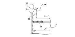
図1,図2,図5に示すように、貯留槽5は上面が開口した四角箱状の槽である。風洞4の下端部が貯留槽5の上面開口部37に上方から挿入されている。図1,図7に示すように、貯留槽5の上面開口部37の内周面と上面開口部37に挿入された風洞4の下端部の外周面との間には隙間38が全周にわたり形成されている。また、貯留槽5内の浄化用水19が隙間38から貯留槽5の外に漏出するのを防止する漏出防止庇39(漏出防止部材の一例)が、貯留槽5の上部内周面に、全周にわたり形成されている。漏出防止庇39は、隙間38の下方において、内側に向いて水平方向に突出した板材である。
As shown in FIGS. 1, 2, and 5, the
浄化用水19は、例えば水道水等の水に次亜塩素酸水等の殺菌剤を混合したものであり、供給装置41によって貯留槽5内から噴霧装置21に供給される。供給装置41は、貯留槽5と噴霧装置21との間に接続された供給管42と、供給管42に設けられたポンプ43とを有している。供給管42には屈曲自在な柔軟性のあるホース等が使用されている。また、ポンプ43は、風洞4の下方でかつ貯留槽5の側方に設置されている。さらに、風洞4の下方でかつ貯留槽5の側方には、貯留槽5内に殺菌剤を注入する殺菌剤注入装置45が設置されている。殺菌剤注入装置45は、殺菌剤を貯留する殺菌剤タンク45a等を有している。
The purifying
図2,図4に示すように、扉8は、裏側に、ケーシング2の内部に突出する突部材47を有している。図2,図3に示すように、扉8を閉じた際、突部材47が風洞4の前板27の上部に対向する。突部材47と前板27との間をシールするシール材48(パッキン等)が突部材47に設けられている。
As shown in FIGS. 2 and 4, the
以下、上記構成における作用を説明する。
送風ファン17を駆動することにより、風洞4内が負圧になり、図2に示すように、外部の空気が、吸気口11から流入口25を通って、風洞4内に導入される。ポンプ43を駆動することにより、貯留槽5内の浄化用水19が、供給管42を通って噴霧装置21に供給され、噴霧装置21から風洞4内に噴霧される。これにより、風洞4内に導入された空気が、風洞4内の気液接触メディア22内で浄化用水19と接触し殺菌されて清浄化され、その後、上部開口部23から負圧室15と送風ファン17と正圧室14とを通り、排気口12から外部へ排出される。また、噴霧装置21から風洞4内に噴霧された浄化用水19は下部開口部24を通って貯留槽5に回収される。
Hereinafter, the operation of the above configuration will be described.
By driving the
また、図6に示すように、風洞4の自重により鍔部30が受け部35に押し付けられて密着するため、風洞4の外部の空気が鍔部30と受け部35との間を通って風洞4の内部に流入するのを防止することができ、風洞4内が負圧に保たれる。
Further, as shown in FIG. 6, since the
また、地震等により貯留槽5が揺れて、貯留槽5内の浄化用水19の水面が波打っても、図7に示すように、貯留槽5の上面開口部37の内周面と風洞4の下端部の外周面との隙間38に浸入しようとする浄化用水19が漏出防止庇39によって遮られる。これにより、貯留槽5内の浄化用水19が上記隙間38を通って貯留槽5の外に漏出するのを防止することができる。
Further, even if the
また、送風ファン17とポンプ43とを停止し、図4に示すように、扉8を開き、風洞4を持ち上げて、風洞4の下端部を貯留槽5の上面開口部37から上方へ脱抜する。この状態で、風洞4を、ケーシング本体7の内部から開口部6を通してケーシング本体7の手前外方へ容易に取り出すことができる。これにより、ケーシング本体7内において、貯留槽5の上方で且つファン装置3の下方に作業のためのスペースを確保することができる。これにより、風洞4の下方に設置されている貯留槽5の清掃やポンプ43又は殺菌剤注入装置45等の保守点検等の作業が上方から容易に行える。
Further, the
上記実施の形態では、水道水等の水に次亜塩素酸水等の殺菌剤を混合した浄化用水19を用いたが、次亜塩素酸水の代わりに、電解水等を用いてもよい。
In the above embodiment, the
1 空気清浄機
2 ケーシング
3 ファン装置
4 風洞
5 貯留槽
6 開口部
8 扉
11 吸気口
12 排気口
19 浄化用水(浄化用液)
21 噴霧装置
30 鍔部(係止部)
35 受け部
37 上面開口部
38 隙間
39 漏出防止庇(漏出防止部材)
DESCRIPTION OF
21
35 Receiving
Claims (4)
ケーシングは、内外に連通する開口部と、開口部を開閉する扉とを有し、
ケーシングの内側に受け部が設けられ、
受け部に上方から受け止められる係止部が風洞の外側に設けられ、
風洞は、貯留槽の上方に位置し、ケーシングに離脱自在に支持され、開口部を通してケーシングの内外に出し入れ自在であり、
風洞内に、貯留槽に貯留された浄化用液を噴霧する噴霧装置が設けられ、
噴霧装置は風洞と一体的にケーシングの内外に出し入れ自在であることを特徴とする空気清浄機。 A wind tunnel and a storage tank are provided in the casing,
The casing has an opening communicating with the inside and the outside, and a door that opens and closes the opening,
A receiving part is provided inside the casing,
A locking part that is received by the receiving part from above is provided outside the wind tunnel,
The wind tunnel is located above the storage tank, is detachably supported by the casing, and can be taken in and out of the casing through the opening,
In the wind tunnel, a spraying device for spraying the cleaning liquid stored in the storage tank is provided,
An air cleaner characterized in that the spraying device can be inserted into and removed from the casing integrally with the wind tunnel.
貯留槽に貯留された浄化用液が、供給管を通って噴霧装置に供給され、噴霧装置から風洞内に噴霧されることを特徴とする請求項1記載の空気清浄機。 A flexible flexible supply pipe is connected between the storage tank and the spray device,
The air cleaner according to claim 1, wherein the cleaning liquid stored in the storage tank is supplied to the spraying device through the supply pipe and sprayed into the wind tunnel from the spraying device.
風洞の下端部が貯留槽の上面開口部に上方から挿入され、
貯留槽の上面開口部の内周面と上面開口部に挿入された風洞の下端部の外周面との間に隙間が形成され、
貯留槽内の浄化用液が隙間から貯留槽外に漏出するのを防止する漏出防止部材が貯留槽内に設けられていることを特徴とする請求項1又は2に記載の空気清浄機。 The reservoir has an open top surface,
The lower end of the wind tunnel is inserted from above into the upper surface opening of the storage tank,
A gap is formed between the inner peripheral surface of the upper surface opening of the storage tank and the outer peripheral surface of the lower end of the wind tunnel inserted into the upper surface opening,
The air purifier according to claim 1 or 2, wherein a leakage preventing member for preventing the purification liquid in the storage tank from leaking out of the storage tank through the gap is provided in the storage tank.
Priority Applications (1)
| Application Number | Priority Date | Filing Date | Title |
|---|---|---|---|
| JP2018092659A JP6556292B2 (en) | 2018-05-14 | 2018-05-14 | Air cleaner |
Applications Claiming Priority (1)
| Application Number | Priority Date | Filing Date | Title |
|---|---|---|---|
| JP2018092659A JP6556292B2 (en) | 2018-05-14 | 2018-05-14 | Air cleaner |
Related Parent Applications (1)
| Application Number | Title | Priority Date | Filing Date |
|---|---|---|---|
| JP2013266206A Division JP2015121375A (en) | 2013-12-25 | 2013-12-25 | Air cleaner |
Publications (2)
| Publication Number | Publication Date |
|---|---|
| JP2018128253A true JP2018128253A (en) | 2018-08-16 |
| JP6556292B2 JP6556292B2 (en) | 2019-08-07 |
Family
ID=63172650
Family Applications (1)
| Application Number | Title | Priority Date | Filing Date |
|---|---|---|---|
| JP2018092659A Active JP6556292B2 (en) | 2018-05-14 | 2018-05-14 | Air cleaner |
Country Status (1)
| Country | Link |
|---|---|
| JP (1) | JP6556292B2 (en) |
Citations (9)
| Publication number | Priority date | Publication date | Assignee | Title |
|---|---|---|---|---|
| US4622077A (en) * | 1984-03-29 | 1986-11-11 | Masahiko Izumi | Method of cleaning the inside of a room |
| JPH0370565A (en) * | 1989-08-11 | 1991-03-26 | Mitsubishi Electric Corp | Deodorizing apparatus |
| JPH10151382A (en) * | 1996-09-27 | 1998-06-09 | Aiwa Co Ltd | Device for spraying liquid such as water |
| JPH11167975A (en) * | 1997-12-05 | 1999-06-22 | Geochto:Kk | Negative ion generator |
| JP2000325727A (en) * | 1999-05-18 | 2000-11-28 | Nikko Sohonsha:Kk | Method and apparatus for generating anion, and water supply tank and automatically water-supplying apparatus in anion-generating apparatus |
| JP2003024768A (en) * | 2001-07-18 | 2003-01-28 | Matsushita Seiko Co Ltd | Negative ion generator |
| JP2007082644A (en) * | 2005-09-21 | 2007-04-05 | Techno Star Kk | Deodorizing device |
| JP2010105619A (en) * | 2008-10-31 | 2010-05-13 | Japan Organo Co Ltd | Vehicular air cleaner |
| JP2015121375A (en) * | 2013-12-25 | 2015-07-02 | 株式会社クボタ | Air cleaner |
-
2018
- 2018-05-14 JP JP2018092659A patent/JP6556292B2/en active Active
Patent Citations (9)
| Publication number | Priority date | Publication date | Assignee | Title |
|---|---|---|---|---|
| US4622077A (en) * | 1984-03-29 | 1986-11-11 | Masahiko Izumi | Method of cleaning the inside of a room |
| JPH0370565A (en) * | 1989-08-11 | 1991-03-26 | Mitsubishi Electric Corp | Deodorizing apparatus |
| JPH10151382A (en) * | 1996-09-27 | 1998-06-09 | Aiwa Co Ltd | Device for spraying liquid such as water |
| JPH11167975A (en) * | 1997-12-05 | 1999-06-22 | Geochto:Kk | Negative ion generator |
| JP2000325727A (en) * | 1999-05-18 | 2000-11-28 | Nikko Sohonsha:Kk | Method and apparatus for generating anion, and water supply tank and automatically water-supplying apparatus in anion-generating apparatus |
| JP2003024768A (en) * | 2001-07-18 | 2003-01-28 | Matsushita Seiko Co Ltd | Negative ion generator |
| JP2007082644A (en) * | 2005-09-21 | 2007-04-05 | Techno Star Kk | Deodorizing device |
| JP2010105619A (en) * | 2008-10-31 | 2010-05-13 | Japan Organo Co Ltd | Vehicular air cleaner |
| JP2015121375A (en) * | 2013-12-25 | 2015-07-02 | 株式会社クボタ | Air cleaner |
Also Published As
| Publication number | Publication date |
|---|---|
| JP6556292B2 (en) | 2019-08-07 |
Similar Documents
| Publication | Publication Date | Title |
|---|---|---|
| JP2015121375A (en) | Air cleaner | |
| US10434204B2 (en) | Technologies for sanitizing mist humidifiers | |
| GB2442378A (en) | Cleaning storage and like tanks | |
| KR20070057486A (en) | A wet air cleaner | |
| WO2018200525A1 (en) | Technologies for sanitizing mist humidifiers | |
| CN206997263U (en) | A kind of condensate drain mouth of pipe dredger | |
| JP6556292B2 (en) | Air cleaner | |
| KR20160014914A (en) | Cleaning apparatus having unmanned monitoring camera | |
| TWI382870B (en) | Dust-removing apparatus and dust-removing system | |
| JP2005214600A (en) | Device and method for cleaning air conditioner | |
| JP6234215B2 (en) | Air cleaner | |
| CN209237656U (en) | A kind of cyclic spraying emission-control equipment | |
| KR101976418B1 (en) | An Module type apparatus on trailer to remove hazardous chemicals and scales from chemical facilities | |
| NO943258L (en) | Dishwasher valve | |
| JP2012000531A (en) | Apparatus including hepa filter for removing contaminant | |
| KR101822959B1 (en) | Heat exchanger cleaning device and its method | |
| KR100919817B1 (en) | Wet type scrabber for exhaust gas capable of cleaning eliminator easily | |
| CN221897918U (en) | Air purifier with disinfection function | |
| JP6555765B1 (en) | Endoscope cleaning device | |
| CN221492816U (en) | Ore crushing equipment | |
| JP2015147606A (en) | Ammonia storage equipment | |
| CN210869208U (en) | Take pig raising house ventilation unit of disinfection mechanism | |
| CN116036323B (en) | Backflow preventing device of pressure steam sterilizer | |
| KR20080002432U (en) | Pneumatic Jet Skin Cleaner Using Carbon Filter for Water Purifier | |
| JP3193464U (en) | Gas cleaning device and draft chamber |
Legal Events
| Date | Code | Title | Description |
|---|---|---|---|
| A621 | Written request for application examination |
Free format text: JAPANESE INTERMEDIATE CODE: A621 Effective date: 20180514 |
|
| A977 | Report on retrieval |
Free format text: JAPANESE INTERMEDIATE CODE: A971007 Effective date: 20190222 |
|
| A131 | Notification of reasons for refusal |
Free format text: JAPANESE INTERMEDIATE CODE: A131 Effective date: 20190305 |
|
| A521 | Request for written amendment filed |
Free format text: JAPANESE INTERMEDIATE CODE: A523 Effective date: 20190401 |
|
| TRDD | Decision of grant or rejection written | ||
| A01 | Written decision to grant a patent or to grant a registration (utility model) |
Free format text: JAPANESE INTERMEDIATE CODE: A01 Effective date: 20190611 |
|
| A61 | First payment of annual fees (during grant procedure) |
Free format text: JAPANESE INTERMEDIATE CODE: A61 Effective date: 20190709 |
|
| R150 | Certificate of patent or registration of utility model |
Ref document number: 6556292 Country of ref document: JP Free format text: JAPANESE INTERMEDIATE CODE: R150 |