JP2018123729A - Oil supply device - Google Patents
Oil supply device Download PDFInfo
- Publication number
- JP2018123729A JP2018123729A JP2017015291A JP2017015291A JP2018123729A JP 2018123729 A JP2018123729 A JP 2018123729A JP 2017015291 A JP2017015291 A JP 2017015291A JP 2017015291 A JP2017015291 A JP 2017015291A JP 2018123729 A JP2018123729 A JP 2018123729A
- Authority
- JP
- Japan
- Prior art keywords
- discharge pressure
- value
- target discharge
- instruction
- oil
- Prior art date
- Legal status (The legal status is an assumption and is not a legal conclusion. Google has not performed a legal analysis and makes no representation as to the accuracy of the status listed.)
- Pending
Links
Images


Landscapes
- Lubrication Of Internal Combustion Engines (AREA)
Abstract
【課題】目標吐出圧に向けて吐出圧センサ値を減少させるべくアクチュエータの操作量を変更しているときにおけるアンダーシュート量を小さくすることができるオイル供給装置を提供する。【解決手段】オイル供給装置210は、目標吐出圧と吐出圧センサ値とを用いたフィードバック制御の比例項と積分項とを用いて指示用目標吐出圧を求めるフィードバック制御部303と、指示用目標吐出圧に対応した指示電流値をアクチュエータ100Aに入力する吐出圧制御部304とを備える。フィードバック制御部303は、目標吐出圧の単位時間あたりの低下量が吐出圧低下量判定値以上であることを条件に、積分項を正の値である規定値と等しくする置換処理を行い、比例項と処理後の積分項とを目標吐出圧に加算して算出した指示用目標吐出圧を求める。【選択図】図1An oil supply device that can reduce an undershoot amount when an operation amount of an actuator is changed to reduce a discharge pressure sensor value toward a target discharge pressure. An oil supply apparatus 210 includes a feedback control unit 303 that obtains an instruction target discharge pressure using a proportional term and an integral term of feedback control using a target discharge pressure and a discharge pressure sensor value, and an instruction target. A discharge pressure control unit 304 that inputs an instruction current value corresponding to the discharge pressure to the actuator 100A. The feedback control unit 303 performs a replacement process to make the integral term equal to a specified value that is a positive value on condition that the amount of decrease in target discharge pressure per unit time is equal to or greater than the discharge pressure decrease amount determination value. An instruction target discharge pressure calculated by adding the term and the processed integral term to the target discharge pressure is obtained. [Selection] Figure 1
Description
本発明は、オイル供給装置に関する。 The present invention relates to an oil supply device.
エンジンには、オイルの供給を必要とする複数のオイル需要部に対してオイルを供給するためのオイル供給装置が設けられている。こうしたオイル供給装置は、オイルポンプと、電動式のアクチュエータと、オイルポンプから吐出されるオイルの圧力を検出するセンサとを備えており、アクチュエータの操作量が変更されると、オイルポンプにおけるオイルの吐出圧が変わるようになっている。 The engine is provided with an oil supply device for supplying oil to a plurality of oil demanding sections that require oil supply. Such an oil supply device includes an oil pump, an electric actuator, and a sensor that detects the pressure of oil discharged from the oil pump. When the operation amount of the actuator is changed, the oil supply in the oil pump is changed. The discharge pressure is changed.
このようなオイル供給装置では、各オイル需要部に十分な量のオイルを供給できるように目標吐出圧が導出され、センサによって検出されているオイルの圧力である吐出圧センサ値と当該目標吐出圧とを用いたフィードバック制御によって、アクチュエータの操作量が導出されるようになっている。例えば特許文献1に記載されているように、目標吐出圧と吐出圧センサ値とに基づいてフィードバック制御の比例項、積分項及び微分項が算出される。そして、これら比例項と積分項と微分項とを目標吐出圧に加算した和に基づいて指示用目標吐出圧が算出され、当該指示用目標吐出圧に対応した操作量が導出され、当該操作量でアクチュエータが作動するようになっている。 In such an oil supply device, a target discharge pressure is derived so that a sufficient amount of oil can be supplied to each oil demand section, and the discharge pressure sensor value that is the pressure of the oil detected by the sensor and the target discharge pressure. The amount of operation of the actuator is derived by feedback control using. For example, as described in Patent Document 1, a proportional term, an integral term, and a differential term for feedback control are calculated based on a target discharge pressure and a discharge pressure sensor value. The instruction target discharge pressure is calculated based on the sum of the proportional term, the integral term, and the derivative term added to the target discharge pressure, and the operation amount corresponding to the instruction target discharge pressure is derived, and the operation amount With this, the actuator is activated.
ところで、目標吐出圧の変更によって目標吐出圧が吐出圧センサ値よりも小さい状態になると、目標吐出圧の低下に追随して吐出圧センサ値が小さくなるようにアクチュエータの操作量が変更されることとなる。このとき、目標吐出圧の低下量が大きいと、吐出圧センサ値が目標吐出圧を一時的に下回るアンダーシュートが発生してしまう。このようにアンダーシュートが発生した場合、目標吐出圧から吐出圧センサ値を減じた差であるアンダーシュート量が大きいと、オイル需要部へのオイルの供給量が同オイル需要部の需要を下回ってしまうことがある。 By the way, when the target discharge pressure becomes smaller than the discharge pressure sensor value due to the change of the target discharge pressure, the operation amount of the actuator is changed so that the discharge pressure sensor value becomes small following the decrease of the target discharge pressure. It becomes. At this time, if the amount of decrease in the target discharge pressure is large, an undershoot occurs in which the discharge pressure sensor value temporarily falls below the target discharge pressure. When undershoot occurs in this way, if the amount of undershoot, which is the difference between the target discharge pressure and the discharge pressure sensor value, is large, the amount of oil supplied to the oil demand department will fall below the demand of the oil demand department. May end up.
本発明の目的は、目標吐出圧に向けて吐出圧センサ値を減少させるべくアクチュエータの操作量を変更しているときにおけるアンダーシュート量を小さくすることができるオイル供給装置を提供することにある。 An object of the present invention is to provide an oil supply device capable of reducing an undershoot amount when an operation amount of an actuator is changed to reduce a discharge pressure sensor value toward a target discharge pressure.
上記課題を解決するためのオイル供給装置は、オイルポンプと、アクチュエータと、オイルポンプから吐出されるオイルの圧力を検出するセンサと、を備え、アクチュエータの操作量が変更されると、オイルポンプにおけるオイルの吐出圧が変わるものである。このオイル供給装置は、オイルポンプに対する吐出圧の目標値である目標吐出圧と、センサによって検出されているオイルの圧力である吐出圧センサ値とを用いたフィードバック制御の比例項と積分項とを当該目標吐出圧に加算して算出した指示用目標吐出圧を求めるフィードバック制御部と、算出された指示用目標吐出圧に対応した操作量に基づいてアクチュエータを作動させることで、オイルポンプにおけるオイルの吐出圧を制御する吐出圧制御部と、を備えている。そして、フィードバック制御部は、目標吐出圧の単位時間あたりの低下量が吐出圧低下量判定値以上であることを条件に、フィードバック制御の積分項を正の値である規定値と等しくする置換処理を行い、フィードバック制御の比例項と処理後の積分項とを目標吐出圧に加算して算出した指示用目標吐出圧を求める。 An oil supply apparatus for solving the above problems includes an oil pump, an actuator, and a sensor that detects a pressure of oil discharged from the oil pump. When the operation amount of the actuator is changed, The oil discharge pressure changes. This oil supply device calculates a proportional term and an integral term of feedback control using a target discharge pressure, which is a target value of the discharge pressure for the oil pump, and a discharge pressure sensor value, which is the oil pressure detected by the sensor. A feedback control unit that obtains a target discharge pressure for instruction calculated by adding to the target discharge pressure, and an actuator that is operated based on an operation amount corresponding to the calculated target discharge pressure for instruction. A discharge pressure control unit that controls the discharge pressure. Then, the feedback control unit replaces the integral term of the feedback control with a specified value that is a positive value on condition that the amount of decrease in target discharge pressure per unit time is equal to or greater than the discharge pressure decrease amount determination value. The instruction target discharge pressure calculated by adding the proportional term of feedback control and the integral term after processing to the target discharge pressure is obtained.
目標吐出圧が吐出圧センサ値よりも小さくなったために吐出圧センサ値を目標吐出圧に向けて減少させる際、目標吐出圧から吐出圧センサ値を引いた差は負の値になる。そのため、比例項は負の値になる。また、目標吐出圧の単位時間あたりの低下量が吐出圧低下量判定値以上であるときには、積分項が大幅に減少し、積分項も負の値になる。こうして積分項も負の値になった場合、当該積分項を用いて算出した指示用目標吐出圧に対応する操作量でアクチュエータを作動させるようにした場合、操作量の変更速度が高くなる、すなわち吐出圧センサ値の減少速度が高くなりやすい。そして、積分項の影響は継続するため、吐出圧センサ値の減少速度が高い状態が継続し、アンダーシュート量が大きくなりやすい。 When the discharge pressure sensor value is decreased toward the target discharge pressure because the target discharge pressure is smaller than the discharge pressure sensor value, the difference obtained by subtracting the discharge pressure sensor value from the target discharge pressure becomes a negative value. Therefore, the proportional term becomes a negative value. Further, when the amount of decrease in the target discharge pressure per unit time is equal to or greater than the discharge pressure decrease amount determination value, the integral term is greatly reduced and the integral term is also a negative value. When the integral term becomes a negative value in this way, when the actuator is operated with the operation amount corresponding to the target discharge pressure for instruction calculated using the integral term, the change amount of the operation amount becomes high, that is, The decrease rate of the discharge pressure sensor value tends to increase. Since the influence of the integral term continues, the state in which the discharge pressure sensor value decreases rapidly continues and the amount of undershoot tends to increase.
そこで、上記構成では、目標吐出圧の単位時間あたりの低下量が吐出圧低下量判定値以上であるときには、フィードバック制御の積分項を正の値である規定値と等しくする置換処理を行い、置換処理後の積分項を用いて指示用目標吐出圧が算出される。そのため、指示用目標吐出圧を、置換処理を行わない場合の積分項を用いる場合と比較して大きくすることができる。その結果、目標吐出圧の単位時間あたりの低下量が吐出圧低下量判定値以上になった時点での指示用目標吐出圧と吐出圧センサ値との乖離が、置換処理を行わない場合と比較して小さくなる。そして、このような指示用目標吐出圧に対応した操作量でアクチュエータを作動させることにより、指示用目標吐出圧と吐出圧センサ値との乖離が大きくなりにくい分、指示用目標吐出圧に対応した操作量の変化速度を低くすることができる。その結果、吐出圧センサ値の減少速度が高くなりにくくなり、ひいては、アンダーシュートの発生が抑制される。したがって、目標吐出圧に向けて吐出圧センサ値を減少させるべくアクチュエータを作動させているときにおけるアンダーシュート量を小さくすることができるようになる。 Therefore, in the above configuration, when the amount of decrease in the target discharge pressure per unit time is equal to or greater than the discharge pressure decrease amount determination value, a replacement process is performed to make the integral term of the feedback control equal to a specified value that is a positive value. The instruction target discharge pressure is calculated using the processed integral term. Therefore, the instruction target discharge pressure can be increased as compared with the case of using the integral term when the replacement process is not performed. As a result, the difference between the target discharge pressure for indication and the discharge pressure sensor value when the amount of decrease in target discharge pressure per unit time is equal to or greater than the discharge pressure decrease amount determination value is compared with the case where no replacement process is performed. And get smaller. Then, by operating the actuator with the operation amount corresponding to the instruction target discharge pressure, the difference between the instruction target discharge pressure and the discharge pressure sensor value is less likely to be large, so that the instruction target discharge pressure is supported. The change rate of the operation amount can be lowered. As a result, the rate of decrease in the discharge pressure sensor value is unlikely to increase, and as a result, the occurrence of undershoot is suppressed. Therefore, the amount of undershoot when the actuator is operated to decrease the discharge pressure sensor value toward the target discharge pressure can be reduced.
また、オイルポンプとして、エンジンのクランク軸の回転に同期して駆動する機関駆動式のオイルポンプが採用されていることがある。この場合、目標吐出圧が変化していない状況下でエンジン回転速度が低下すると、吐出圧センサ値が小さくなる。すると、アクチュエータの作動によって吐出圧センサ値が目標吐出圧まで増大されることとなる。このとき、吐出圧センサ値が目標吐出圧を下回っている状態が長く続くと、エンジンにおけるオイル需要部でオイルの量の不足を招いてしまうおそれがある。 An engine-driven oil pump that is driven in synchronism with the rotation of the crankshaft of the engine may be employed as the oil pump. In this case, the discharge pressure sensor value decreases when the engine speed decreases in a situation where the target discharge pressure has not changed. Then, the discharge pressure sensor value is increased to the target discharge pressure by the operation of the actuator. At this time, if the state where the discharge pressure sensor value is lower than the target discharge pressure continues for a long time, there is a risk that the amount of oil in the oil demand section of the engine will be insufficient.
そこで、フィードバック制御部は、エンジン回転速度の単位時間あたりの低下量が回転速度低下量判定値以上であることを条件に、フィードバック制御の積分項を負の値としない処理を行い、フィードバック制御の比例項と当該処理後の積分項とを目標吐出圧に加算して算出した指示用目標吐出圧を求めるようにしてもよい。吐出圧センサ値が目標吐出圧を下回っている状況下で積分項が負の値になってしまうと、吐出圧センサ値の増大速度が高くなりにくくなり、吐出圧センサ値が目標吐出圧を下回っている状態が長期に亘って継続してしまう。この点、上記構成によれば、エンジン回転速度の単位時間あたりの低下量が回転速度低下量判定値以上であるときには、積分項が「0」以上の値となるため、目標吐出圧と吐出圧センサ値との乖離が小さくなりにくい。すなわち、吐出圧センサ値の増大速度が低くなりにくい。その結果、吐出圧センサ値が目標吐出圧を下回っている状態が長期に亘って継続されにくくなる。 Therefore, the feedback control unit performs processing that does not set the integral term of the feedback control to a negative value on the condition that the amount of decrease in the engine speed per unit time is equal to or greater than the rotational speed decrease determination value. The target discharge pressure for instruction calculated by adding the proportional term and the integral term after the processing to the target discharge pressure may be obtained. If the integral term becomes a negative value when the discharge pressure sensor value is lower than the target discharge pressure, the increase rate of the discharge pressure sensor value is difficult to increase, and the discharge pressure sensor value falls below the target discharge pressure. Will continue for a long time. In this regard, according to the above configuration, when the amount of decrease in the engine rotational speed per unit time is equal to or greater than the rotational speed decrease determination value, the integral term is a value equal to or greater than “0”. Deviation from sensor value is unlikely to be small. That is, the increase rate of the discharge pressure sensor value is unlikely to decrease. As a result, the state where the discharge pressure sensor value is lower than the target discharge pressure is difficult to continue for a long time.
なお、目標吐出圧が低下したために吐出圧センサ値を減少させる場合、目標吐出圧の単位時間あたりの低下量が大きいほど、フィードバック制御の比例項の絶対値が大きくなりやすい。すなわち、吐出圧センサ値の減少速度が高くなりやすい。そこで、上記オイル供給装置は、目標吐出圧の単位時間あたりの低下量が大きいほど規定値を大きくする規定値設定部を備えることが好ましい。 When the discharge pressure sensor value is decreased because the target discharge pressure has decreased, the absolute value of the proportional term of the feedback control tends to increase as the amount of decrease in the target discharge pressure per unit time increases. That is, the decrease rate of the discharge pressure sensor value tends to increase. Therefore, it is preferable that the oil supply device includes a specified value setting unit that increases the specified value as the amount of decrease in the target discharge pressure per unit time increases.
上記構成によれば、目標吐出圧の単位時間あたりの低下量が大きいほど、置換処理によって積分項を大きくすることができる。このような積分項を用いて指示用目標吐出圧を算出することで、目標吐出圧の単位時間あたりの低下量が大きいために比例項の絶対値が大きくなっても、吐出圧センサ値の減少速度が高くなりにくくなる。その結果、アンダーシュート量が大きくなることを抑制できる。 According to the above configuration, the integral term can be increased by the replacement process as the amount of decrease in the target discharge pressure per unit time is larger. By calculating the target discharge pressure for indication using such an integral term, even if the absolute value of the proportional term increases because the amount of decrease in target discharge pressure per unit time is large, the discharge pressure sensor value decreases. The speed is difficult to increase. As a result, it is possible to suppress an increase in the amount of undershoot.
なお、フィードバック制御部は、置換処理によって導出した積分項を用いて算出した指示用目標吐出圧に対応した操作量でアクチュエータが作動されたあとでは、置換処理を行っていない積分項を用いて指示用目標吐出圧を算出することが好ましい。これにより、置換処理によって導出した積分項が使用され続ける場合と比較し、吐出圧センサ値の減少速度が低くなりすぎることを抑制できる。 The feedback control unit uses the integral term that has not been subjected to the replacement process after the actuator is operated with the operation amount corresponding to the target discharge pressure for instruction calculated using the integral term derived by the replacement process. It is preferable to calculate the target discharge pressure. Thereby, compared with the case where the integral term derived | led-out by the substitution process continues being used, it can suppress that the decreasing rate of a discharge pressure sensor value becomes low too much.
また、目標吐出圧が低下したものの、その単位時間あたりの低下量がそれほど大きくないときに、置換処理によって導出した積分項を用いて算出した指示用目標吐出圧に対応した操作量でアクチュエータを作動させた場合、吐出圧センサ値の減少速度が低くなりすぎ、吐出圧センサ値が目標吐出圧に収束するのに要する時間が長くなりすぎてしまう。そこで、上記吐出圧低下量判定値を、第1の吐出圧低下量判定値とした場合、フィードバック制御部は、目標吐出圧の単位時間あたりの低下量が、第1の吐出圧低下量判定値未満であって、且つ、同第1の吐出圧低下量判定値よりも小さい第2の吐出圧低下量判定値以上であることを条件に、フィードバック制御の積分項を「0」と等しくする他の置換処理を行い、フィードバック制御の比例項と当該処理後の積分項とを目標吐出圧に加算して算出した指示用目標吐出圧を求めるようにしてもよい。 Also, when the target discharge pressure is reduced, but the reduction amount per unit time is not so large, the actuator is operated with the operation amount corresponding to the target discharge pressure for indication calculated using the integral term derived by the replacement process. In this case, the decrease rate of the discharge pressure sensor value becomes too low, and the time required for the discharge pressure sensor value to converge to the target discharge pressure becomes too long. Therefore, when the discharge pressure decrease amount determination value is the first discharge pressure decrease amount determination value, the feedback control unit determines that the decrease amount per unit time of the target discharge pressure is the first discharge pressure decrease amount determination value. Other than making the integral term of the feedback control equal to “0” on condition that it is less than or equal to or greater than the second discharge pressure decrease amount determination value smaller than the first discharge pressure decrease amount determination value. The instruction target discharge pressure calculated by adding the proportional term of the feedback control and the integral term after the process to the target discharge pressure may be obtained.
上記構成によれば、目標吐出圧の単位時間あたりの低下量が、第1の吐出圧低下量判定値未満であって、且つ、第2の吐出圧低下量判定値以上であるときには、他の置換処理によって導出した積分項を用いて指示用目標吐出圧が算出される。他の置換処理によって導出される積分項は、置換処理によって導出される積分項よりも小さい。そのため、指示用目標吐出圧と吐出圧センサ値との乖離は、置換処理によって導出される積分項を用いて指示用目標吐出圧を算出する場合と比較して大きくなる。そして、このような指示用目標吐出圧に対応した操作量でアクチュエータを作動させることにより、置換処理によって導出される積分項を用いて算出した指示用目標吐出圧に対応する操作量でアクチュエータを作動させる場合と比較し、吐出圧センサ値の減少速度を高くできる。その結果、吐出圧センサ値が目標吐出圧に収束するのに要する時間が長くなってしまうことを抑制できる。 According to the above configuration, when the amount of decrease in the target discharge pressure per unit time is less than the first discharge pressure decrease amount determination value and greater than or equal to the second discharge pressure decrease amount determination value, The instruction target discharge pressure is calculated using the integral term derived by the replacement process. The integral term derived by the other replacement process is smaller than the integral term derived by the replacement process. Therefore, the difference between the instruction target discharge pressure and the discharge pressure sensor value is larger than that in the case where the instruction target discharge pressure is calculated using the integral term derived by the replacement process. Then, by operating the actuator with the operation amount corresponding to the instruction target discharge pressure, the actuator is operated with the operation amount corresponding to the instruction target discharge pressure calculated using the integral term derived by the replacement process. Compared with the case of making it, the decreasing speed of a discharge pressure sensor value can be made high. As a result, it is possible to suppress an increase in the time required for the discharge pressure sensor value to converge to the target discharge pressure.
以下、オイル供給装置の一実施形態を図1〜図8に従って説明する。
図1には、本実施形態のオイル供給装置210を備えるエンジン200におけるオイルの循環経路が図示されている。図1に示すように、エンジン200は、オイルを貯留しているオイルパン201と、オイルパン201内のオイルがオイル供給装置210を介して供給されるメインオイルギャラリ202とを備えている。また、エンジン200には、オイルの供給を必要とする複数のデバイス203が設けられている。これら各デバイス203が、オイルの供給の必要な部分であるオイル需要部の一例である。そして、デバイス203から排出されたオイルが、オイルパン201に戻るようになっている。
Hereinafter, an embodiment of an oil supply device will be described with reference to FIGS.
FIG. 1 illustrates an oil circulation path in an
オイル供給装置210は、オイルの吐出圧を変更可能なオイルポンプ10と、オイル制御バルブ100とを備えている。そして、制御装置300がオイル制御バルブ100の駆動を制御することで、オイルポンプ10におけるオイルの吐出圧が変更されるようになっている。
The
次に、図1、図2及び図3を参照し、オイルポンプ10について説明する。
オイルポンプ10は、エンジン200のクランク軸の回転に基づいて駆動する可変容量型のポンプである。図2及び図3に示すように、オイルポンプ10は、クランク軸と同期して回転する入力軸11と、内部に収容空間40が区画されているケーシング部材CSとを備えている。この収容空間40には、入力軸11と一体回転するインナロータ50と、インナロータ50よりも外周側に配置されているアウタロータ60と、アウタロータ60を取り囲むリング状の調整リング70とが設けられている。
Next, the
The
ケーシング部材CSには、その内部にオイルを吸入する吸入ポート12と、内部のオイルをケーシング部材CS外に吐出する吐出ポート13とが設けられている。なお、図1に示すように吸入ポート12はオイルパン201に通じる吸入油路114に連通しており、図2及び図3に示すように吐出ポート13はメインオイルギャラリ202に通じる吐出油路13aに連通している。
The casing member CS is provided with a
図2及び図3に示すように、インナロータ50の外周には複数の外歯51が設けられており、アウタロータ60の内周には、インナロータ50の外歯51と噛み合う複数の内歯61が設けられている。内歯61の数は外歯51の数よりも1つ多くなっている。そして、アウタロータ60は、調整リング70によって回転可能に保持されている。
As shown in FIGS. 2 and 3, a plurality of
アウタロータ60の回転中心は、インナロータ50の回転中心に対して偏心している。インナロータ50の外歯51とアウタロータ60の内歯61とは、それらの一部分(図2では右側部分)が互いに噛み合った状態となっている。インナロータ50の外周とアウタロータ60の内周との間には、オイルにより満たされる作動室41が形成されている。
The rotation center of the
作動室41において、インナロータ50の外歯51とアウタロータ60の内歯61とが互いに噛み合う位置から図2に矢印で示す入力軸11の回転方向における所定位置までの部分では、各ロータ50,60の回転に伴ってインナロータ50の外歯51とアウタロータ60の内歯61との間の隙間が徐々に大きくなる。そして、このようにインナロータ50の外歯51とアウタロータ60の内歯61との間の隙間が徐々に大きくなる部分が、吸入ポート12と連通する。一方、作動室41において、ロータ50,60の回転に伴ってインナロータ50の外歯51とアウタロータ60の内歯61との間の隙間が徐々に小さくなる部分が、吐出ポート13と連通する。
In the working chamber 41, in a portion from a position where the
オイルポンプ10が駆動する際には、入力軸11が回転することにより、各ロータ50,60が互いに噛み合いながら回転する。そして、オイルパン201に貯留されているオイルが吸入油路114を介して吸入ポート12から作動室41に吸入され、吐出ポート13から吐出油路13aに吐出される。
When the
調整リング70は、アウタロータ60を保持するリング状の本体部71と、本体部71の外周からロータ50,60の径方向に突出する突出部72とを有している。調整リング70の本体部71には、規定方向に延びる長孔711,712が設けられている。これら長孔711,712には、ケーシング部材CSに固定されているガイドピン81,82が挿通されている。これにより、調整リング70は、長孔711,712の延びる方向に変位可能となっている。
The
調整リング70の突出部72の先端には第1のシール部材83が設けられているとともに、本体部71には第2のシール部材84が設けられている。各シール部材83,84はケーシング部材CSの側壁に当接し、側壁と調整リング70の外周との間の空間がシールされることにより、収容空間40には、調整リング70及び各シール部材83,84によって制御油室42が区画形成されている。
A
制御油室42には、制御油路111と連通する開口部14が設けられており、この制御油路111及び開口部14を通じてオイル制御バルブ100から制御油室42にオイルが供給可能となっている。また、収容空間40には、制御油室42の容積を小さくする方向への付勢力を突出部72に付与するスプリング15が設けられている。このスプリング15は、突出部72を挟んだ制御油室42の反対側に配設されている。図2には、制御油室42の内圧が低いため、スプリング15からの付勢力によって、制御油室42の容積が最小となる位置で調整リング70が保持されている状態が示されている。なお、本実施形態では、このように制御油室42の容積が最小となるときの調整リング70の位置、すなわち図2での調整リング70の位置を、「初期位置」というものとする。
The
そして、調整リング70が初期位置に配置されている状況下で、制御油室42にオイルが供給され、制御油室42の内圧が高くなると、スプリング15からの付勢力に抗し、制御油室42の容積を大きくする方向に初期位置から調整リング70が変位する。すなわち、図2に示す状態から図3に示す状態に向かう方向(図2における反時計回り方向)に調整リング70が回動しながら変位する。一方、オイル制御バルブ100の駆動によって制御油室42からオイルが排出されるようになると、制御油室42の内圧が低くなり、スプリング15からの付勢力によって、制御油室42の容積を小さくする方向に調整リング70が変位する。すなわち、図3に示す状態から図2に示す状態に向かう方向(図3における時計回り方向)に調整リング70が回動しながら変位する。つまり、調整リング70の位置は、制御油室42の内圧とスプリング15からの付勢力とによって決まる。そして、調整リング70の位置の変化によって、吸入ポート12及び吐出ポート13の各々の開口に対するインナロータ50及びアウタロータ60の歯51,61の噛み合う部分の相対的な位置が変化する。このため、制御油室42の内圧の調整による調整リング70の位置の変更を通じ、吐出ポート13から吐出されるオイルの圧力である吐出圧が変更される。
When the
具体的には、オイルポンプ10では、図2に示されているように調整リング70の位置が「初期位置」にあるときに、オイルの吐出圧が最大になる。図2に示すようにオイルの吐出圧が最大となる位置にある状態から制御油室42の内圧が高くなると、内圧の上昇に伴い、調整リング70が、スプリング15からの付勢力に抗して図2における反時計回り方向に回動しながら変位する。その結果、ロータ50,60の回転に伴って外歯51と内歯61との間の隙間が徐々に大きくなる部分のうち、吸入ポート12と重なる範囲が小さくなるとともに、外歯51と内歯61との間の隙間が徐々に小さくなる部分の一部が吸入ポート12と重なるようになる。その結果、オイルの吐出圧が低くなる。反対に、制御油室42の内圧が低くなると、内圧の低下に伴い、調整リング70が、スプリング15からの付勢力によって図3における時計回り方向に回動しながら変位し、オイルの吐出圧が高くなる。
Specifically, in the
次に、図1、図2及び図3を参照し、オイル制御バルブ100について説明する。
図1及び図2に示すように、オイル制御バルブ100は、電磁駆動式のアクチュエータ100Aの駆動によってスプールの位置を切り替えることにより複数の油路の連通状態を切り替えることができる。すなわち、オイル制御バルブ100は、制御油路111が接続される制御ポート101と、オイルポンプ10の吐出油路13aから分岐する供給油路112が接続される供給ポート102と、オイルを排出するための排出油路113が接続される排出ポート103とを備えている。そして、アクチュエータ100Aに対する指示電流値Iocvの調整によってスプールの位置を変化させることにより、同スプールの位置が、制御ポート101に還流してきたオイルを排出ポート103から排出する排出位置(図2)と、供給ポート102に供給されるオイルを制御ポート101から制御油路111に送り出す供給位置(図3)との間で切り替わるようになっている。すなわち、本実施形態では、アクチュエータ100Aの操作量、すなわちアクチュエータ100Aに入力する指示電流値Iocvが大きくなるにつれて、スプールが、図2に示す位置から図3に示す位置に向けて変位するようになる。このように図2に示す位置から図3に示す位置に向けてスプールを変位させることで、オイルポンプ10の制御油室42の内圧を高くすることができる、すなわちオイルポンプ10におけるオイルの吐出圧を低くすることができる。
Next, the
As shown in FIGS. 1 and 2, the
次に、図1及び図4を参照し、オイル供給装置210の制御装置300について説明する。
図1に示すように、制御装置300には、吐出圧センサ311と、温度センサ312と、クランク角センサ313とが電気的に接続されている。吐出圧センサ311はオイルポンプ10から吐出されたオイルの圧力である吐出圧センサ値PSを検出し、温度センサ312はオイルポンプ10に供給されるオイルの温度である油温TMPを検出する。また、クランク角センサ313は、クランク軸の回転速度であるエンジン回転速度NEを検出する。そして、制御装置300は、これら各センサ311〜313によって検出された情報を基に、オイル供給装置210の作動を制御するようになっている。
Next, the
As shown in FIG. 1, a
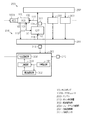
また、制御装置300は、オイルポンプ10におけるオイルの吐出圧を制御するための機能部として、目標設定部301、規定値設定部302、フィードバック制御部303及び吐出圧制御部304を有している。
In addition, the
目標設定部301は、オイルポンプ10に対する目標吐出圧PTrを設定する。具体的には、目標設定部301は、上記各デバイス203における要求油圧を個別に導出し、各要求油圧のうち、最も高い要求油圧、又は最も高い要求油圧よりもやや高い油圧を目標吐出圧PTrとする。また、目標設定部301は、エンジン回転速度NEが予め設定された所定速度領域A内の値となっている場合、目標吐出圧PTrを所定値で保持する。そして、目標設定部301は、設定した目標吐出圧PTrを規定値設定部302及びフィードバック制御部303に出力する。
The
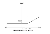
規定値設定部302は、目標吐出圧PTrの単位時間あたりの低下量DPTrに応じて規定値Fを設定する。具体的には、図4に示すように、規定値設定部302は、低下量DPTrが第1の吐出圧低下量判定値DPTrTh1未満である場合、「0」よりも大きい最小値Fminと等しくする。すなわち、目標吐出圧PTrが低下していない場合でも、規定値Fが最小値Fminと等しくされる。また、規定値設定部302は、低下量DPTrが第1の吐出圧低下量判定値DPTrTh1以上である場合、低下量DPTrが大きいほど規定値Fを大きくする。そのため、規定値Fは、必ず正の値となる。そして、規定値設定部302は、導出した規定値Fをフィードバック制御部303に出力する。
The specified value setting unit 302 sets the specified value F according to the decrease amount DPTr per unit time of the target discharge pressure PTr. Specifically, as shown in FIG. 4, the specified value setting unit 302 equals the minimum value Fmin greater than “0” when the decrease amount DPTr is less than the first discharge pressure decrease amount determination value DPTrTh1. . That is, even when the target discharge pressure PTr is not lowered, the specified value F is made equal to the minimum value Fmin. Further, when the decrease amount DPTr is equal to or greater than the first discharge pressure decrease amount determination value DPTrTh1, the specified value setting unit 302 increases the specified value F as the decrease amount DPTr increases. Therefore, the specified value F is always a positive value. Then, the specified value setting unit 302 outputs the derived specified value F to the
図1に示すように、フィードバック制御部303は、指示用目標吐出圧PTrAを算出するための処理として、第1の指示値算出処理、第2の指示値算出処理及び第3の指示値算出処理を実施可能である。各算出処理の内容については後述する。すなわち、フィードバック制御部303は、状況に応じて算出処理を使い分けている。そして、フィードバック制御部303は、これら算出処理によって算出した指示用目標吐出圧PTrAを吐出圧制御部304に出力する。
As illustrated in FIG. 1, the
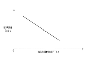
吐出圧制御部304は、フィードバック制御部303から入力された指示用目標吐出圧PTrAに対応した指示電流値Iocvを算出する。指示電流値Iocvが、アクチュエータ100Aの操作量の一例である。本実施形態では、図5に示すように、指示電流値Iocvは、指示用目標吐出圧PTrAが小さいほど大きくなる。そして、吐出圧制御部304は、算出した指示電流値Iocvをアクチュエータ100Aに入力することで、アクチュエータ100Aの作動を制御する、すなわちオイルポンプ10におけるオイルの吐出圧を制御する。
The discharge pressure control unit 304 calculates an instruction current value Iocv corresponding to the instruction target discharge pressure PTrA input from the
次に、図6を参照し、指示用目標吐出圧PTrAを算出するためにフィードバック制御部303が実行する処理ルーチンについて説明する。なお、この処理ルーチンは、予め設定された制御サイクル毎に実行される。
Next, a processing routine executed by the
図6に示すように、本処理ルーチンにおいて、フィードバック制御部303は、定常状態であるか否かを判定する(ステップS11)。定常状態とは、吐出圧センサ値PSが目標吐出圧PTrに収束している状態のことであり、吐出圧センサ値PSが目標吐出圧PTrに収束していない状態のことを非定常状態という。そして、定常状態である場合(ステップS11:YES)、フィードバック制御部303は、後述する補正フラグFLGにオフをセットし(ステップS12)、第1の指示値算出処理を行う(ステップS13)。すなわち、フィードバック制御部303は、目標吐出圧PTrと吐出圧センサ値PSとを用いたフィードバック制御の比例項Xと積分項Yとを算出する。そして、フィードバック制御部303は、算出した比例項Xと積分項Yとを目標吐出圧PTrに加算して算出した指示用目標吐出圧PTrAを求める。具体的には、フィードバック制御部303は、目標吐出圧PTr、比例項X及び積分項Yを以下に示す関係式(式1)に代入することで、指示用目標吐出圧PTrAを算出する。なお、関係式(式1)における「G」は共通のゲインであり、ゲインGは、オイルポンプ10に供給されるオイルの温度、すなわち温度センサ312によって検出されている油温TMPに応じた値に設定される。
As shown in FIG. 6, in this processing routine, the
PTrA=(PTr+X+Y)×G ・・・(式1)
そして、第1の指示値算出処理で指示用目標吐出圧PTrAを算出すると、フィードバック制御部303は、その処理を後述するステップS21に移行する。
PTrA = (PTr + X + Y) × G (Formula 1)
When the instruction target discharge pressure PTrA is calculated in the first instruction value calculation process, the
その一方で、ステップS11において、定常状態ではない場合(NO)、フィードバック制御部303は、補正フラグFLGにオフがセットされているか否かを判定する(ステップS14)。補正フラグFLGにオンがセットされている場合(ステップS14:NO)、フィードバック制御部303は、その処理を前述したステップS13に移行する。一方、補正フラグFLGにオフがセットされている場合(ステップS14:YES)、フィードバック制御部303は、エンジン回転速度NEが所定速度領域A内で変化していることと、エンジン回転速度NEの単位時間あたりの低下量DNEが回転速度低下量判定値DNETh以上であることとの双方が成立しているか否かを判定する(ステップS15)。ここでいう「単位時間」とは、上記制御サイクルの一周期の時間の長さと等しい。
On the other hand, in step S11, when it is not a steady state (NO), the
本処理ルーチンの前回の実行時におけるエンジン回転速度NEが所定速度領域A内の値であり、且つ、本処理ルーチンの今回の実行時におけるエンジン回転速度NE、すなわち現在のエンジン回転速度NEが所定速度領域A内の値である場合、エンジン回転速度NEが所定速度領域A内で変化していると判定することができる。この場合、目標吐出圧PTrが所定値で保持されていると判定することができる。一方、以下に示す3つの条件のうち少なくとも1つの条件が成立している場合、エンジン回転速度NEが所定速度領域A内で変化していると判定することができない。
(条件1)本処理ルーチンの前回の実行時におけるエンジン回転速度NEと、本処理ルーチンの今回の実行時におけるエンジン回転速度NEとがほぼ同等である場合。
(条件2)本処理ルーチンの前回の実行時におけるエンジン回転速度NEが所定速度領域A内の値ではない場合。
(条件3)本処理ルーチンの今回の実行時におけるエンジン回転速度NE、すなわち現在のエンジン回転速度NEが所定速度領域A内の値ではない場合。
The engine speed NE at the previous execution of this processing routine is a value within the predetermined speed region A, and the engine speed NE at the current execution of this processing routine, that is, the current engine speed NE is the predetermined speed. When the value is within the region A, it can be determined that the engine rotational speed NE is changing within the predetermined speed region A. In this case, it can be determined that the target discharge pressure PTr is held at a predetermined value. On the other hand, when at least one of the following three conditions is satisfied, it cannot be determined that the engine speed NE changes within the predetermined speed region A.
(Condition 1) The engine speed NE at the previous execution of this processing routine is substantially equal to the engine speed NE at the current execution of this processing routine.
(Condition 2) The engine speed NE at the previous execution of this processing routine is not a value within the predetermined speed region A.
(Condition 3) When the engine speed NE at the current execution of this processing routine, that is, the current engine speed NE is not a value within the predetermined speed region A.
また、目標吐出圧PTrが変化していない状況下で、エンジン回転速度NEが低下すると、吐出圧センサ値PSが目標吐出圧PTr未満の状態になる。このとき、低下量DNEが大きいと、各デバイス203でオイルの供給量不足が発生するおそれがある。そこで、エンジン回転速度NEの低下に起因して吐出圧センサ値PSと目標吐出圧PTrとの乖離が大きくなる可能性があるか否かを判定できるように、回転速度低下量判定値DNEThが設定されている。
Further, when the engine rotational speed NE is decreased under the condition where the target discharge pressure PTr is not changed, the discharge pressure sensor value PS becomes less than the target discharge pressure PTr. At this time, if the decrease amount DNE is large, there is a possibility that the supply amount of oil in each
そして、エンジン回転速度NEが所定速度領域A内で変化していることと、低下量DNEが回転速度低下量判定値DNETh以上であることとの双方が成立している場合(ステップS15:YES)、フィードバック制御部303は、その処理を後述するステップS18に移行する。一方、エンジン回転速度NEが所定速度領域A内で変化していることと、低下量DNEが回転速度低下量判定値DNETh以上であることとの何れか一方が成立していない場合(ステップS15:NO)、フィードバック制御部303は、目標吐出圧PTrの単位時間あたりの低下量DPTrが第2の吐出圧低下量判定値DPTrTh2以上であるか否かを判定する(ステップS16)。
When both the engine speed NE changes within the predetermined speed region A and the decrease amount DNE is greater than or equal to the rotation speed decrease amount determination value DNETh are satisfied (step S15: YES). The
なお、目標吐出圧PTrが吐出圧センサ値PSよりも小さくなったために吐出圧センサ値PSを目標吐出圧PTrに向けて減少させる際、目標吐出圧PTrから吐出圧センサ値PSを引いた差は負の値になる。そのため、比例項Xは負の値になる。また、低下量DPTrが大きいと、積分項Yが大幅に減少し、積分項Yも負の値になる。そこで、本実施形態では、低下量DPTrが第2の吐出圧低下量判定値DPTrTh2以上であるときには積分項Yが負の値となるように、第2の吐出圧低下量判定値DPTrTh2が設定されている。 When the discharge pressure sensor value PS is decreased toward the target discharge pressure PTr because the target discharge pressure PTr is smaller than the discharge pressure sensor value PS, the difference obtained by subtracting the discharge pressure sensor value PS from the target discharge pressure PTr is Negative value. Therefore, the proportional term X becomes a negative value. Further, when the decrease amount DPTr is large, the integral term Y is significantly reduced, and the integral term Y becomes a negative value. Therefore, in the present embodiment, the second discharge pressure decrease amount determination value DPTrTh2 is set so that the integral term Y becomes a negative value when the decrease amount DPTr is equal to or greater than the second discharge pressure decrease amount determination value DPTrTh2. ing.
そして、低下量DPTrが第2の吐出圧低下量判定値DPTrTh2未満である場合(ステップS16:NO)、フィードバック制御部303は、その処理を前述したステップS13に移行する。一方、低下量DPTrが第2の吐出圧低下量判定値DPTrTh2以上である場合(ステップS16:YES)、フィードバック制御部303は、低下量DPTrが第1の吐出圧低下量判定値DPTrTh1以上であるか否かを判定する(ステップS17)。第1の吐出圧低下量判定値DPTrTh1は、第2の吐出圧低下量判定値DPTrTh2よりも大きい値に設定されている。そのため、低下量DPTrが第1の吐出圧低下量判定値DPTrTh1以上である場合、当然、積分項Yは負の値となる。
When the decrease amount DPTr is less than the second discharge pressure decrease amount determination value DPTrTh2 (step S16: NO), the
そして、低下量DPTrが第1の吐出圧低下量判定値DPTrTh1以上である場合(ステップS17:YES)、フィードバック制御部303は、その処理を次のステップS18に移行する。
If the decrease amount DPTr is equal to or greater than the first discharge pressure decrease amount determination value DPTrTh1 (step S17: YES), the
ステップS18において、フィードバック制御部303は、第2の指示値算出処理を行う。すなわち、フィードバック制御部303は、目標吐出圧PTrと吐出圧センサ値PSとを用いたフィードバック制御の比例項Xと積分項Yとを算出する処理と、積分項Yを、規定値設定部302によって導出された規定値Fに置き換える置換処理とを行う。そして、フィードバック制御部303は、算出した比例項Xと置換処理によって導出した積分項Yとを、上記関係式(式1)に代入することで指示用目標吐出圧PTrAを求める。
In step S18, the
上述したように、目標吐出圧PTrが吐出圧センサ値PSよりも小さくなったために吐出圧センサ値PSを目標吐出圧PTrに向けて減少させる際、低下量DPTrが第1の吐出圧低下量判定値DPTrTh1以上であるときには、フィードバック制御の積分項Yも負の値になる。 As described above, when the discharge pressure sensor value PS is decreased toward the target discharge pressure PTr because the target discharge pressure PTr is smaller than the discharge pressure sensor value PS, the decrease amount DPTr is determined as the first discharge pressure decrease amount determination. When the value is greater than or equal to value DPTrTh1, the integral term Y of the feedback control is also a negative value.
これに対し、規定値Fは、正の値であるとともに、図4に示すように低下量DPTrが大きいほど大きくなる。そのため、本実施形態では、このように吐出圧センサ値PSを目標吐出圧PTrに向けて減少させる際、積分項Yを必ず「0」よりも大きい値とすることができる。つまり、第1の指示値算出処理は積分項Yを何ら補正することなく、当該積分項Yを用いて指示用目標吐出圧PTrAを求める処理であるのに対し、第2の指示値算出処理は、積分項Yを正の値とし、当該積分項Yを用いて指示用目標吐出圧PTrAを求める処理である。 On the other hand, the prescribed value F is a positive value and increases as the decrease amount DPTr increases as shown in FIG. Therefore, in the present embodiment, when the discharge pressure sensor value PS is decreased toward the target discharge pressure PTr in this way, the integral term Y can always be set to a value larger than “0”. That is, the first instruction value calculation process is a process of obtaining the instruction target discharge pressure PTrA using the integral term Y without correcting the integral term Y, whereas the second instruction value calculation process is In this process, the integral term Y is set to a positive value, and the instruction target discharge pressure PTrA is obtained using the integral term Y.
図6に戻り、第2の指示値算出処理で指示用目標吐出圧PTrAを算出すると、フィードバック制御部303は、その処理を後述するステップS20に移行する。
その一方で、ステップS17において、低下量DPTrが第1の吐出圧低下量判定値DPTrTh1未満である場合(NO)、フィードバック制御部303は、第3の指示値算出処理を行う(ステップS19)。すなわち、フィードバック制御部303は、目標吐出圧PTrと吐出圧センサ値PSとを用いたフィードバック制御の比例項X及び積分項Yを算出する処理と、積分項Yを「0」と等しくする他の置換処理を行う。そして、フィードバック制御部303は、算出した比例項Xと他の置換処理によって導出した積分項Yとを、上記関係式(式1)に代入することで指示用目標吐出圧PTrAを求める。
Returning to FIG. 6, when the instruction target discharge pressure PTrA is calculated in the second instruction value calculation process, the
On the other hand, when the decrease amount DPTr is less than the first discharge pressure decrease amount determination value DPTrTh1 in step S17 (NO), the
他の置換補正によって導出された積分項Yは、何ら補正を行っていない積分項Yよりも大きく、且つ、規定値Fよりも小さい。そのため、指示用目標吐出圧PTrAを、第1の指示値算出処理によって算出する場合よりも大きく、第2の指示値算出処理によって算出する場合よりも小さくすることができる。そして、第3の指示値算出処理で指示用目標吐出圧PTrAを算出すると、フィードバック制御部303は、その処理を次のステップS20に移行する。
The integral term Y derived by the other replacement correction is larger than the integral term Y without any correction and smaller than the specified value F. Therefore, the instruction target discharge pressure PTrA can be made larger than that calculated by the first instruction value calculation process and smaller than that calculated by the second instruction value calculation process. When the target discharge pressure PTrA is calculated in the third instruction value calculation process, the
第1の指示値算出処理は積分項Yを何ら補正することなく、当該積分項Yを用いて指示用目標吐出圧PTrAを求める処理であるのに対し、第3の指示値算出処理は、積分項Yを「0」にリセットするための他の置換処理を行い、当該積分項Yを用いて指示用目標吐出圧PTrAを求める処理である。 The first instruction value calculation process is a process of obtaining the instruction target discharge pressure PTrA using the integral term Y without correcting the integral term Y, whereas the third instruction value calculation process is an integral This is a process of performing another replacement process for resetting the term Y to “0” and obtaining the instruction target discharge pressure PTrA using the integral term Y.
ステップS20において、フィードバック制御部303は、補正フラグFLGにオンをセットする。すなわち、補正フラグFLGは、第1の指示値算出処理とは異なる他の算出処理、すなわち第2の指示値算出処理又は第3の指示値算出処理で指示用目標吐出圧PTrAを算出したときにオンがセットされるフラグである。そして、フィードバック制御部303は、その処理を次のステップS21に移行する。
In step S20, the
そして、ステップS21において、フィードバック制御部303は、ステップS13又はステップS18又はステップS19で算出した指示用目標吐出圧PTrAを吐出圧制御部304に出力する。その後、フィードバック制御部303は、本処理ルーチンを一旦終了する。
In step S21, the
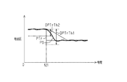
次に、図7を参照し、目標吐出圧PTrが低下したために第2の指示値算出処理が実施される際の作用を効果とともに説明する。なお、図7における太い実線は、低下量DPTrが第1の吐出圧低下量判定値DPTrTh1以上になったタイミングである規定タイミングで第2の指示値用算出処理によって算出した指示用目標吐出圧PTrAに対応する指示電流値Iocvをアクチュエータ100Aに入力する本実施形態での吐出圧センサ値PSの推移を示している。一方、図7における破線は、規定タイミングでも第1の指示値用算出処理によって算出した指示用目標吐出圧PTrAに対応する指示電流値Iocvをアクチュエータ100Aに入力する比較例での吐出圧センサ値PSの推移を示している。
Next, with reference to FIG. 7, the operation when the second instruction value calculation process is performed because the target discharge pressure PTr has decreased will be described together with effects. Note that the thick solid line in FIG. 7 indicates the instruction target discharge pressure PTrA calculated by the second instruction value calculation process at a specified timing at which the decrease amount DPTr becomes equal to or greater than the first discharge pressure decrease amount determination value DPTrTh1. The transition of the discharge pressure sensor value PS in the present embodiment in which the command current value Iocv corresponding to is input to the
図7に示すように、定常状態である第1のタイミングt11で目標吐出圧PTrが小さくなると、定常状態から非定常状態に移行する。図7に示す例では、第1のタイミングt11での低下量DPTrが第1の吐出圧低下量判定値DPTrTh1以上である。そのため、規定タイミングである第1のタイミングt11では、第1の指示値用算出処理及び第3の指示値用算出処理ではなく、第2の指示値用算出処理によって指示用目標吐出圧PTrAが算出される。 As shown in FIG. 7, when the target discharge pressure PTr decreases at the first timing t11 in the steady state, the steady state is shifted to the unsteady state. In the example illustrated in FIG. 7, the decrease amount DPTr at the first timing t11 is equal to or greater than the first discharge pressure decrease amount determination value DPTrTh1. Therefore, at the first timing t11, which is the specified timing, the instruction target discharge pressure PTrA is calculated not by the first instruction value calculation process and the third instruction value calculation process but by the second instruction value calculation process. Is done.
ここで、図7に破線で示す比較例では、第1のタイミングt11でも第1の指示値用算出処理によって指示用目標吐出圧PTrAが算出される。このように目標吐出圧PTrが吐出圧センサ値PSよりも小さくなったために吐出圧センサ値PSを目標吐出圧PTrに向けて減少させる際、目標吐出圧PTrと吐出圧センサ値PSとを用いたフィードバック制御の積分項Y、すなわち何ら補正を行っていない積分項Yは負の値となる。そして、比較例では、この積分項Yを用いる第1の指示値用算出処理によって算出した指示用目標吐出圧PTrAに対応する指示電流値Iocvがアクチュエータ100Aに入力される。その結果、図7に破線で示すように、アンダーシュートが発生し、このアンダーシュート終了後にオーバーシュートが発生し、その後、吐出圧センサ値PSが目標吐出圧PTrに収束するようになる。
Here, in the comparative example indicated by the broken line in FIG. 7, the instruction target discharge pressure PTrA is calculated by the first instruction value calculation process even at the first timing t11. As described above, when the discharge pressure sensor value PS is decreased toward the target discharge pressure PTr because the target discharge pressure PTr is smaller than the discharge pressure sensor value PS, the target discharge pressure PTr and the discharge pressure sensor value PS are used. The integral term Y of the feedback control, that is, the integral term Y without any correction is a negative value. In the comparative example, the command current value Iocv corresponding to the command target discharge pressure PTrA calculated by the first command value calculation process using the integral term Y is input to the
これに対し、本実施形態では、第1のタイミングt11では、第2の指示値用算出処理によって指示用目標吐出圧PTrAを算出している。第2の指示値算出処理では、置換処理によって導出された規定値Fが積分項Yに代入され、当該積分項Yを用いて指示用目標吐出圧PTrAが算出される。この積分項Yは、何ら補正を行っていない積分項Yよりも大きい。よって、指示用目標吐出圧PTrAを、第1の指示値算出処理によって算出する場合よりも大きくすることができる。その結果、第1のタイミングt11での指示用目標吐出圧PTrAと吐出圧センサ値PSとの乖離は、比較例の場合よりも小さくなる。そして、第2の指示値算出処理によって算出した指示用目標吐出圧PTrAに対応した指示電流値Iocvをアクチュエータ100Aに入力することにより、第1のタイミングt11よりもあとでは、第1の指示値算出処理によって算出される指示用目標吐出圧PTrAに対応した指示電流値Iocvの変化速度を低くすることができる。その結果、図7に実線で示すように、吐出圧センサ値PSの減少速度が比較例の場合よりも低くなるため、アンダーシュートの発生が抑制される。したがって、目標吐出圧PTrに向けて吐出圧センサ値PSを減少させるべくアクチュエータ100Aに入力する指示電流値Iocvを変更しているときにおけるアンダーシュート量を小さくすることができる。また、アンダーシュート終了後のオーバーシュート量も、比較例の場合よりも小さくすることができる。
In contrast, in the present embodiment, at the first timing t11, the instruction target discharge pressure PTrA is calculated by the second instruction value calculation process. In the second command value calculation process, the specified value F derived by the replacement process is substituted into the integral term Y, and the command target discharge pressure PTrA is calculated using the integral term Y. This integral term Y is larger than the integral term Y without any correction. Therefore, the instruction target discharge pressure PTrA can be made larger than that calculated by the first instruction value calculation process. As a result, the difference between the instruction target discharge pressure PTrA and the discharge pressure sensor value PS at the first timing t11 is smaller than that in the comparative example. Then, by inputting the command current value Iocv corresponding to the command target discharge pressure PTrA calculated by the second command value calculation process to the
なお、本実施形態では、規定タイミングである第1のタイミングt11での低下量DPTrが大きいほど、規定値Fが大きくなる。そのため、低下量DPTrが大きいために負の値となるフィードバック制御の比例項Xの絶対値が大きくなる場合ほど、指示用目標吐出圧PTrAの算出に用いられる積分項Yを大きくすることができる。したがって、吐出圧センサ値PSを目標吐出圧PTrに向けて減少させる際における吐出圧センサ値PSの減少速度が高くなりすぎることを抑制でき、ひいては、アンダーシュート量が大きくなることを抑制できる。 In the present embodiment, the specified value F increases as the decrease amount DPTr at the first timing t11, which is the specified timing, increases. Therefore, the integral term Y used to calculate the target discharge pressure PTrA can be increased as the absolute value of the proportional term X of the feedback control that becomes a negative value because the decrease amount DPTr is larger. Therefore, it is possible to suppress the decrease rate of the discharge pressure sensor value PS when the discharge pressure sensor value PS is decreased toward the target discharge pressure PTr from being excessively increased, and thus it is possible to suppress an increase in the amount of undershoot.
また、本実施形態では、規定タイミングでは、第2の指示値算出処理によって算出した積分項Y(=規定値F)を用いて指示用目標吐出圧PTrAを算出している一方で、規定タイミングよりもあとでは、第1の指示値算出処理によって算出した積分項Yを用いて指示用目標吐出圧PTrAを算出している。そのため、規定タイミングよりもあとでも第2の指示値算出処理によって算出した積分項Yを用いた指示用目標吐出圧PTrAの算出が行われる場合と比較し、吐出圧センサ値PSの減少速度が低くなりすぎることを抑制できる。 Further, in the present embodiment, at the specified timing, the target discharge pressure PTrA for instruction is calculated using the integral term Y (= specified value F) calculated by the second instruction value calculation process. Thereafter, the target discharge pressure PTrA for instruction is calculated using the integral term Y calculated by the first instruction value calculation process. Therefore, compared with the case where the target target discharge pressure PTrA is calculated using the integral term Y calculated by the second instruction value calculation process even after the specified timing, the rate of decrease in the discharge pressure sensor value PS is low. It can suppress becoming too much.
次に、図8を参照し、目標吐出圧PTrが低下したために第3の指示値算出処理を行う場合の作用を効果とともに説明する。なお、図8における太い実線は、低下量DPTrが第2の吐出圧低下量判定値DPTrTh2以上になったタイミングである規定タイミングで第3の指示値用算出処理によって算出した指示用目標吐出圧PTrAに対応する指示電流値Iocvをアクチュエータ100Aに入力する場合の吐出圧センサ値PSの推移を示している。一方、図7における破線は、規定タイミングで第2の指示値用算出処理によって算出した指示用目標吐出圧PTrAに対応する指示電流値Iocvをアクチュエータ100Aに入力する場合の吐出圧センサ値PSの推移を示している。
Next, with reference to FIG. 8, the operation when the third instruction value calculation process is performed because the target discharge pressure PTr has decreased will be described together with effects. Note that the thick solid line in FIG. 8 indicates the instruction target discharge pressure PTrA calculated by the third instruction value calculation process at a specified timing at which the decrease amount DPTr becomes equal to or greater than the second discharge pressure decrease amount determination value DPTrTh2. The transition of the discharge pressure sensor value PS when the command current value Iocv corresponding to is input to the
図8に示すように、第1のタイミングt21で目標吐出圧PTrが小さくなると、定常状態から非定常状態に移行する。図8に示す例では、第1のタイミングt21での低下量DPTrは、第2の吐出圧低下量判定値DPTrTh2以上ではあるものの、第1の吐出圧低下量判定値DPTrTh1未満であるため、吐出圧センサ値PSと目標吐出圧PTrとの乖離はあまり大きくないと判断することができる。そのため、第1のタイミングt21では、第2の指示値用算出処理ではなく、第3の指示値用算出処理によって指示用目標吐出圧PTrAが算出される。 As shown in FIG. 8, when the target discharge pressure PTr becomes small at the first timing t21, the steady state shifts to the unsteady state. In the example shown in FIG. 8, the decrease amount DPTr at the first timing t21 is equal to or greater than the second discharge pressure decrease amount determination value DPTrTh2, but is less than the first discharge pressure decrease amount determination value DPTrTh1, It can be determined that the difference between the pressure sensor value PS and the target discharge pressure PTr is not so large. Therefore, at the first timing t21, the instruction target discharge pressure PTrA is calculated not by the second instruction value calculation process but by the third instruction value calculation process.
ここで、第1のタイミングt21での低下量DPTrが第1の吐出圧低下量判定値DPTrTh1未満であっても第2の指示値算出処理によって算出した指示用目標吐出圧PTrAに対応する指示電流値Iocvをアクチュエータ100Aに入力したとする。この場合、図8に破線で示すように、第1のタイミングt21よりもあとでの指示電流値Iocvの変更速度が低い分、吐出圧センサ値PSの減少速度が低くなる。その結果、アンダーシュート量を小さくすることができるものの、第1のタイミングt21から吐出圧センサ値PSが目標吐出圧PTrに収束するまでに要する時間が長くなる。
Here, even if the decrease amount DPTr at the first timing t21 is less than the first discharge pressure decrease amount determination value DPTrTh1, the instruction current corresponding to the instruction target discharge pressure PTrA calculated by the second instruction value calculation process It is assumed that the value Iocv is input to the
これに対し、本実施形態では、規定タイミングである第1のタイミングt21での低下量DPTrが、第2の吐出圧低下量判定値DPTrTh2以上であって、且つ、第1の吐出圧低下量判定値DPTrTh1未満であるときには、第3の指示値算出処理によって指示用目標吐出圧PTrAが算出される。置換処理によって積分項Yを正の値とする第2の指示値算出処理によって指示用目標吐出圧PTrAを算出する場合と比較し、第3の指示値算出処理では、積分項Yを「0」と等しくしているため、指示用目標吐出圧PTrAを小さくすることができる。そのため、第1のタイミングt21での指示用目標吐出圧PTrAと吐出圧センサ値PSとの乖離は、第2の指示値算出処理によって指示用目標吐出圧PTrAを算出する場合と比較して大きくなる。そして、第1のタイミングt21で第3の指示値算出処理によって算出した指示用目標吐出圧PTrAに対応する指示電流値Iocvをアクチュエータ100Aに入力することにより、第1のタイミングt21よりもあとでは、第1の指示値算出処理によって算出された指示用目標吐出圧に対応する指示電流値Iocvの変化速度を高くすることができる。その結果、第2の指示値算出処理によって算出された指示用目標吐出圧PTrAに対応する指示電流値Iocvをアクチュエータ100Aに入力する場合と比較し、吐出圧センサ値PSの減少速度を高くでき、ひいては、吐出圧センサ値PSが目標吐出圧PTrに収束するのに要する時間を短くすることができる。
On the other hand, in the present embodiment, the decrease amount DPTr at the first timing t21 that is the specified timing is equal to or greater than the second discharge pressure decrease amount determination value DPTrTh2, and the first discharge pressure decrease amount determination When the value is less than the value DPTrTh1, the instruction target discharge pressure PTrA is calculated by the third instruction value calculation process. Compared to the case where the instruction target discharge pressure PTrA is calculated by the second instruction value calculation process in which the integral term Y is a positive value by the replacement process, the integral term Y is set to “0” in the third instruction value calculation process. Therefore, the instruction target discharge pressure PTrA can be reduced. Therefore, the difference between the instruction target discharge pressure PTrA and the discharge pressure sensor value PS at the first timing t21 is larger than that in the case where the instruction target discharge pressure PTrA is calculated by the second instruction value calculation process. . Then, by inputting the command current value Iocv corresponding to the command target discharge pressure PTrA calculated by the third command value calculation process at the first timing t21 to the
なお、第3の指示値算出処理によって算出された指示用目標吐出圧PTrAは、第2の指示値算出処理によって算出された指示用目標吐出圧PTrAよりは小さいものの、第1の指示値算出処理によって算出された指示用目標吐出圧PTrAよりは大きい。そのため、第1のタイミングt21で第1の指示値算出処理によって指示用目標吐出圧PTrAを算出し、この指示用目標吐出圧PTrAに対応する指示電流値Iocvをアクチュエータ100Aに入力する場合と比較し、指示電流値Iocvの減少速度を低くすることができる。その結果、アンダーシュート量を小さくすることができる。
Although the instruction target discharge pressure PTrA calculated by the third instruction value calculation process is smaller than the instruction target discharge pressure PTrA calculated by the second instruction value calculation process, the first instruction value calculation process is performed. Is larger than the instruction target discharge pressure PTrA calculated by. Therefore, the instruction target discharge pressure PTrA is calculated by the first instruction value calculation process at the first timing t21, and the instruction current value Iocv corresponding to the instruction target discharge pressure PTrA is input to the
また、本実施形態では、規定タイミングでは、第3の指示値算出処理によって算出した積分項Y(=0)を用いて指示用目標吐出圧PTrAを算出している一方で、規定タイミングよりもあとでは、第1の指示値算出処理によって算出した積分項Yを用いて指示用目標吐出圧PTrAを算出している。そのため、規定タイミングよりもあとでも第3の指示値算出処理によって算出した積分項Yを用いた指示用目標吐出圧PTrAの算出が行われる場合と比較し、吐出圧センサ値PSの減少速度が低くなりすぎることを抑制できる。 In the present embodiment, at the specified timing, the target discharge pressure PTrA for instruction is calculated using the integral term Y (= 0) calculated by the third instruction value calculation process, but after the specified timing. The instruction target discharge pressure PTrA is calculated using the integral term Y calculated by the first instruction value calculation process. Therefore, the decrease rate of the discharge pressure sensor value PS is lower than when the target target discharge pressure PTrA is calculated using the integral term Y calculated by the third instruction value calculation process even after the specified timing. It can suppress becoming too much.
次に、エンジン回転速度NEが所定速度領域A内で低下したために第2の指示値算出処理が実施される際の作用を効果とともに説明する。
オイルポンプ10は、クランク軸の回転に同期して駆動する機関駆動式のポンプであるため、エンジン回転速度NEが低くなると、オイルポンプ10におけるオイルの吐出圧が低くなる。すなわち、目標吐出圧PTrを吐出圧センサ値PSが下回るようになる。吐出圧センサ値PSが目標吐出圧PTrまで増大されるように、オイルポンプ10の作動が制御される。このとき、エンジン回転速度NEが所定速度領域A内で低下した場合、その単位時間あたりの低下量DNEが回転速度低下量判定値DNETh以上であると、第2の指示値用算出処理によって指示用目標吐出圧PTrAが算出される。そのため、指示用目標吐出圧PTrAの算出に用いられる積分項Yは、必ず負の値にならない。そして、この指示用目標吐出圧PTrAに対応した指示電流値Iocvがアクチュエータ100Aに入力される。そのため、第1の指示値用算出処理によって指示用目標吐出圧PTrAが算出される場合と比較し、吐出圧センサ値PSの増大速度が低くなりにくい。その結果、吐出圧センサ値PSを早期に目標吐出圧PTrまで増大させることができる。
Next, the operation when the second instruction value calculation process is performed because the engine speed NE has decreased in the predetermined speed region A will be described together with effects.
Since the
また、本実施形態では、低下量DNEが回転速度低下量判定値DNETh以上であると判定されたタイミングでは、第2の指示値算出処理によって算出した積分項Y(=規定値F)を用いて指示用目標吐出圧PTrAを算出している一方で、当該タイミングよりもあとでは、第1の指示値算出処理によって算出した積分項Yを用いて指示用目標吐出圧PTrAを算出している。そのため、当該タイミングよりもあとでも第2の指示値算出処理によって算出した積分項Yを用いた指示用目標吐出圧PTrAの算出が行われる場合と比較し、吐出圧センサ値PSの増大速度が高くなりすぎることを抑制できる。 In this embodiment, at the timing when it is determined that the decrease amount DNE is equal to or greater than the rotational speed decrease amount determination value DNETh, the integral term Y (= specified value F) calculated by the second instruction value calculation process is used. While the instruction target discharge pressure PTrA is calculated, the instruction target discharge pressure PTrA is calculated using the integral term Y calculated by the first instruction value calculation process after the timing. For this reason, the increase rate of the discharge pressure sensor value PS is higher than when the target target discharge pressure PTrA is calculated using the integral term Y calculated by the second instruction value calculation process even after the timing. It can suppress becoming too much.
なお、上記実施形態は以下のような別の実施形態に変更してもよい。
・第3の指示値算出処理では、積分項Yを「0」とは僅かに異なる値に置き換え、当該積分項Yを用いて指示用目標吐出圧PTrAを算出するようにしてもよい。
The above embodiment may be changed to another embodiment as described below.
In the third instruction value calculation process, the integral term Y may be replaced with a value slightly different from “0”, and the instruction target discharge pressure PTrA may be calculated using the integral term Y.
・目標吐出圧の単位時間あたりの低下量DPTrが第1の吐出圧低下量判定値DPTrTh1以上である場合において規定値Fを低下量DPTrが大きいほど大きくできるのであれば、低下量DPTrが大きくなるときには規定値Fを段階的に大きくするようにしてもよい。 If the decrease amount DPTr per unit time of the target discharge pressure is greater than or equal to the first discharge pressure decrease amount determination value DPTrTh1, if the specified value F can be increased as the decrease amount DPTr increases, the decrease amount DPTr increases. Sometimes, the specified value F may be increased stepwise.
・目標吐出圧の単位時間あたりの低下量DPTrが第1の吐出圧低下量判定値DPTrTh1未満であっても、規定値Fを、低下量DPTrに応じて可変させるようにしてもよい。 The specified value F may be varied according to the decrease amount DPTr even if the decrease amount DPTr per unit time of the target discharge pressure is less than the first discharge pressure decrease amount determination value DPTrTh1.
・エンジン回転速度NEが所定速度領域A内で変化していることと、エンジン回転速度NEの単位時間あたりの低下量DNEが回転速度低下量判定値DNETh以上であることとの双方が成立している場合、規定値Fを、低下量DNEが大きいほど大きくなるようにしてもよい。 -Both the engine speed NE changes within the predetermined speed region A and the decrease amount DNE per unit time of the engine speed NE is greater than or equal to the rotation speed decrease amount determination value DNETh. If so, the specified value F may be increased as the decrease amount DNE is larger.
・規定値Fは、目標吐出圧の単位時間あたりの低下量DPTrによらず、予め決められた一定の値で固定してもよい。ただし、この一定の値は正の値である。
・目標吐出圧の単位時間あたりの低下量DPTrが第1の吐出圧低下量判定値DPTrTh1未満であるときには「0」よりも大きい第1の値で規定値Fを固定し、低下量DPTrが第1の吐出圧低下量判定値DPTrTh1以上であるときには、第1の値よりも大きい第2の値で規定値Fを固定するようにしてもよい。
The specified value F may be fixed at a predetermined value regardless of the reduction amount DPTr per unit time of the target discharge pressure. However, this constant value is a positive value.
When the decrease amount DPTr per unit time of the target discharge pressure is less than the first discharge pressure decrease amount determination value DPTrTh1, the specified value F is fixed at a first value larger than “0”, and the decrease amount DPTr is When the discharge pressure decrease amount determination value DPTrTh1 is equal to or greater than 1, the specified value F may be fixed at a second value larger than the first value.
・目標吐出圧PTrは低下したものの、その単位時間あたりの低下量DPTrが第1の吐出圧低下量判定値DPTrTh1未満であって且つ第2の吐出圧低下量判定値DPTrTh2以上であるときには、第1の指示電流値算出処理によって算出した指示用目標吐出圧PTrAに対応する指示電流値Iocvのアクチュエータ100Aへの入力を継続させるようにしてもよい。
When the target discharge pressure PTr has decreased, but the decrease amount DPTr per unit time is less than the first discharge pressure decrease amount determination value DPTrTh1 and not less than the second discharge pressure decrease amount determination value DPTrTh2, The command current value Iocv corresponding to the command target discharge pressure PTrA calculated by the command current value calculation process 1 may be continuously input to the
・エンジン回転速度NEが所定速度領域A内で変化していることと、エンジン回転速度NEの単位時間あたりの低下量DNEが回転速度低下量判定値DNETh以上であることとの双方が成立している場合、負の値ではない積分項Yを用いて指示用目標吐出圧PTrAを算出できるのであれば、第2の指示値算出処理とは異なる別の処理を実施するようにしてもよい。例えば、別の処理は、第3の指示値算出処理であってもよい。また、別の処理は、上記置換処理や上記他の置換処理を何ら行わないで算出した積分項Yと、所定値とのうち大きい方の値を積分項Yとし、この積分項Yを用いて指示用目標吐出圧PTrAを算出する処理であってもよい。この場合、所定値は、「0」と等しい値又は「0」よりも大きい値に設定されることとなる。 -Both the engine speed NE changes within the predetermined speed region A and the decrease amount DNE per unit time of the engine speed NE is greater than or equal to the rotation speed decrease amount determination value DNETh. If the target discharge pressure PTrA for instruction can be calculated using the integral term Y that is not a negative value, a process different from the second instruction value calculation process may be performed. For example, the other process may be a third instruction value calculation process. Another process is to use the integral term Y as the integral term Y, which is the larger of the integral term Y calculated without performing the above substitution processing or any other substitution processing, and the predetermined value. Processing for calculating the target discharge pressure PTrA for instruction may be used. In this case, the predetermined value is set to a value equal to “0” or a value greater than “0”.
・上記実施形態では、目標吐出圧PTrが小さくなったり、エンジン回転速度NEが低くなったりし、第2の指示値算出処理又は第3の指示値算出処理を実施する場合、第1の指示値算出処理ではない他の算出処理で算出した指示用目標吐出圧PTrAに対応する指示電流値Iocvをアクチュエータ100Aに1回入力したあとでは、第1の指示値算出処理で算出した指示用目標吐出圧PTrAに対応する指示電流値Iocvがアクチュエータ100Aに入力される。しかし、これに限らず、第2の指示値算出処理又は第3の指示値算出処理を実施する場合、規定期間の間、上記他の算出処理で算出した指示用目標吐出圧PTrAに対応する指示電流値Iocvをアクチュエータ100Aに入力し続け、そのあとに第1の指示値算出処理で算出した指示用目標吐出圧PTrAに対応する指示電流値Iocvをアクチュエータ100Aに入力するようにしてもよい。
In the above embodiment, when the target discharge pressure PTr is decreased or the engine rotational speed NE is decreased and the second instruction value calculation process or the third instruction value calculation process is performed, the first instruction value After the command current value Iocv corresponding to the command target discharge pressure PTrA calculated by another calculation process that is not the calculation process is input once to the
・上記実施形態では、フィードバック制御の比例項Xと積分項Yとを用いて指示用目標吐出圧PTrAを算出するようにしているが、比例項X及び積分項Yに加えて微分項をも用いて指示用目標吐出圧PTrAを算出するようにしてもよい。 In the above embodiment, the target target discharge pressure PTrA is calculated using the proportional term X and the integral term Y of the feedback control. However, in addition to the proportional term X and the integral term Y, a differential term is also used. Thus, the target discharge pressure PTrA for instruction may be calculated.
・上記実施形態では、オイル供給装置210は、オイルポンプ10としてギヤポンプを備えている。しかし、オイル供給装置210は、ギヤポンプ以外の他の種類のポンプ(例えば、ベーンポンプ)をオイルポンプ10として備えた構成であってもよい。
In the above embodiment, the
・オイルポンプは、機関駆動式のポンプではなく、電動式のポンプであってもよい。この場合、オイルポンプを駆動させるための電動モータがアクチュエータに相当することとなり、この電動モータの回転速度、すなわち電動モータに対する指示電流値を調整することによってオイルポンプにおけるオイルの吐出圧を制御することができる。このような電動式のオイルポンプを備えるオイル供給装置では、目標吐出圧PTrが低下し、吐出圧センサ値PSと目標吐出圧PTrとの乖離が大きいと判定できるときには、第2の指示値算出処理又は第3の指示値算出処理によって指示用目標吐出圧PTrAを算出し、この指示用目標吐出圧PTrAに対応する指示電流値を、電動モータに入力することとなる。そして、こうした指示電流値を電動モータに入力したあとでは、第1の指示値算出処理によって算出した指示用目標吐出圧PTrAに対応する指示電流値を電動モータに入力することにより、アンダーシュートの発生を抑制することができる。 The oil pump may be an electric pump instead of an engine driven pump. In this case, the electric motor for driving the oil pump corresponds to the actuator, and the oil discharge pressure in the oil pump is controlled by adjusting the rotation speed of the electric motor, that is, the command current value for the electric motor. Can do. In the oil supply apparatus including such an electric oil pump, when the target discharge pressure PTr decreases and it can be determined that the difference between the discharge pressure sensor value PS and the target discharge pressure PTr is large, the second instruction value calculation process is performed. Alternatively, the instruction target discharge pressure PTrA is calculated by the third instruction value calculation process, and the instruction current value corresponding to the instruction target discharge pressure PTrA is input to the electric motor. After such an instruction current value is input to the electric motor, an undershoot occurs by inputting an instruction current value corresponding to the instruction target discharge pressure PTrA calculated by the first instruction value calculation process to the electric motor. Can be suppressed.
なお、このような電動式のオイルポンプを備えるオイル供給装置では、電動モータの回転速度は、エンジン回転速度NEとは同期していない。そのため、エンジン回転速度NEが低くなっても、電動モータの回転速度が高くならない限り第2の指示値算出処理によって算出した指示用目標吐出圧PTrAに対応する指示電流値を電動モータに入力することはない。 In the oil supply device including such an electric oil pump, the rotation speed of the electric motor is not synchronized with the engine rotation speed NE. Therefore, even if the engine rotational speed NE decreases, the command current value corresponding to the command target discharge pressure PTrA calculated by the second command value calculation process is input to the electric motor as long as the rotation speed of the electric motor does not increase. There is no.
10…オイルポンプ、100A…アクチュエータ、200…エンジン、210…オイル供給装置、302…規定値設定部、303…フィードバック制御部、304…吐出圧制御部、311…吐出圧センサ。
DESCRIPTION OF
Claims (5)
前記オイルポンプに対する吐出圧の目標値である目標吐出圧と、前記センサによって検出されているオイルの圧力である吐出圧センサ値とを用いたフィードバック制御の比例項と積分項とを当該目標吐出圧に加算して算出した指示用目標吐出圧を求めるフィードバック制御部と、
算出された指示用目標吐出圧に対応した操作量に基づいて前記アクチュエータを作動させることで、前記オイルポンプにおけるオイルの吐出圧を制御する吐出圧制御部と、を備え、
前記フィードバック制御部は、前記目標吐出圧の単位時間あたりの低下量が吐出圧低下量判定値以上であることを条件に、前記フィードバック制御の積分項を正の値である規定値と等しくする置換処理を行い、前記フィードバック制御の比例項と当該処理後の積分項とを前記目標吐出圧に加算して算出した指示用目標吐出圧を求める
オイル供給装置。 An oil supply device comprising an oil pump, an actuator, and a sensor for detecting the pressure of oil discharged from the oil pump, wherein the oil discharge pressure in the oil pump changes when the operation amount of the actuator is changed Because
A proportional term and an integral term of feedback control using a target discharge pressure, which is a target value of the discharge pressure for the oil pump, and a discharge pressure sensor value, which is the pressure of oil detected by the sensor, are represented by the target discharge pressure. A feedback control unit for obtaining a target discharge pressure for instruction calculated by adding to
A discharge pressure control unit that controls the discharge pressure of oil in the oil pump by operating the actuator based on an operation amount corresponding to the calculated target discharge pressure for instruction,
The feedback control unit replaces the integral term of the feedback control with a specified value that is a positive value on condition that the amount of decrease in the target discharge pressure per unit time is equal to or greater than the discharge pressure decrease amount determination value. An oil supply device that performs processing and obtains a target discharge pressure for instruction calculated by adding the proportional term of the feedback control and the integral term after the processing to the target discharge pressure.
前記フィードバック制御部は、エンジン回転速度の単位時間あたりの低下量が回転速度低下量判定値以上であることを条件に、前記フィードバック制御の積分項を負の値としない処理を行い、前記フィードバック制御の比例項と当該処理後の積分項とを前記目標吐出圧に加算して算出した指示用目標吐出圧を求める
請求項1に記載のオイル供給装置。 The oil pump is driven in synchronization with the rotation of the crankshaft of the engine,
The feedback control unit performs a process that does not set the integral term of the feedback control to be a negative value on condition that the amount of decrease in the engine rotational speed per unit time is equal to or greater than the rotational speed decrease amount determination value. The oil supply apparatus according to claim 1, wherein an instruction target discharge pressure calculated by adding a proportional term of the above and an integral term after the processing to the target discharge pressure is obtained.
請求項1又は請求項2に記載のオイル供給装置。 The oil supply apparatus according to claim 1, further comprising a specified value setting unit that increases the specified value as the amount of decrease in the target discharge pressure per unit time increases.
請求項1に記載のオイル供給装置。 The feedback control unit uses an integral term that is not subjected to the substitution process after the actuator is operated with an operation amount corresponding to the target discharge pressure for instruction calculated using the integral term derived by the substitution process. The oil supply apparatus according to claim 1, wherein the target discharge pressure for instruction is calculated.
前記フィードバック制御部は、前記目標吐出圧の単位時間あたりの低下量が、前記第1の吐出圧低下量判定値未満であって、且つ、同第1の吐出圧低下量判定値よりも小さい第2の吐出圧低下量判定値以上であることを条件に、前記フィードバック制御の積分項を「0」と等しくする他の置換処理を行い、前記フィードバック制御の比例項と当該処理後の積分項とを前記目標吐出圧に加算して算出した指示用目標吐出圧を求める
請求項1〜請求項4のうち何れか一項に記載のオイル供給装置。 When the discharge pressure decrease amount determination value is the first discharge pressure decrease amount determination value,
The feedback control unit has a first reduction amount of the target discharge pressure per unit time that is less than the first discharge pressure drop amount determination value and smaller than the first discharge pressure drop amount determination value. 2 on the condition that the discharge pressure decrease amount determination value is equal to or greater than 2, another substitution process is performed to make the integral term of the feedback control equal to “0”, and the proportional term of the feedback control and the integral term after the processing The oil supply device according to any one of claims 1 to 4, wherein an instruction target discharge pressure is calculated by adding to the target discharge pressure.
Priority Applications (1)
| Application Number | Priority Date | Filing Date | Title |
|---|---|---|---|
| JP2017015291A JP2018123729A (en) | 2017-01-31 | 2017-01-31 | Oil supply device |
Applications Claiming Priority (1)
| Application Number | Priority Date | Filing Date | Title |
|---|---|---|---|
| JP2017015291A JP2018123729A (en) | 2017-01-31 | 2017-01-31 | Oil supply device |
Publications (1)
| Publication Number | Publication Date |
|---|---|
| JP2018123729A true JP2018123729A (en) | 2018-08-09 |
Family
ID=63111203
Family Applications (1)
| Application Number | Title | Priority Date | Filing Date |
|---|---|---|---|
| JP2017015291A Pending JP2018123729A (en) | 2017-01-31 | 2017-01-31 | Oil supply device |
Country Status (1)
| Country | Link |
|---|---|
| JP (1) | JP2018123729A (en) |
-
2017
- 2017-01-31 JP JP2017015291A patent/JP2018123729A/en active Pending
Similar Documents
| Publication | Publication Date | Title |
|---|---|---|
| EP2657526B1 (en) | Oil pump | |
| CN109253083B (en) | Hydraulic control device and hydraulic control method | |
| JP2009167811A (en) | Valve timing adjusting device | |
| JP6200164B2 (en) | Variable displacement vane pump | |
| JP2016223320A (en) | Oil pump control device of engine | |
| JP2018123729A (en) | Oil supply device | |
| JP6086364B2 (en) | Oil pump | |
| CN110088454B (en) | Control device and control method for vehicle-mounted engine | |
| US9903366B2 (en) | Variable displacement vane pump | |
| JP2018123714A (en) | Oil viscosity estimation device | |
| JP2018123730A (en) | Oil supply device | |
| JP2016098768A (en) | Oil pump | |
| JP2020029787A (en) | Oil supply device | |
| US11008906B2 (en) | Oil supply device for engine mounted in vehicle | |
| JP6954642B2 (en) | Exhaust system and exhaust system control method | |
| JP5386452B2 (en) | Hydraulic actuator control device | |
| JP5447194B2 (en) | Control device for internal combustion engine | |
| JP2017180367A (en) | Variable displacement oil pump | |
| JP2018155140A (en) | Oil supply device of engine | |
| JP2019044671A (en) | Pump device | |
| JP6823186B2 (en) | Control method of compressed gas supply device and compressed gas supply device | |
| JP2016017450A (en) | Variable displacement vane pump | |
| JP7081167B2 (en) | Oil supply device | |
| JP2007051622A (en) | Hydraulic supply pump | |
| JP2017223132A (en) | Variable displacement oil pump device |