JP2018123714A - Oil viscosity estimation device - Google Patents
Oil viscosity estimation device Download PDFInfo
- Publication number
- JP2018123714A JP2018123714A JP2017014767A JP2017014767A JP2018123714A JP 2018123714 A JP2018123714 A JP 2018123714A JP 2017014767 A JP2017014767 A JP 2017014767A JP 2017014767 A JP2017014767 A JP 2017014767A JP 2018123714 A JP2018123714 A JP 2018123714A
- Authority
- JP
- Japan
- Prior art keywords
- oil
- discharge pressure
- response time
- viscosity
- time
- Prior art date
- Legal status (The legal status is an assumption and is not a legal conclusion. Google has not performed a legal analysis and makes no representation as to the accuracy of the status listed.)
- Pending
Links
Images


Abstract
Description
本発明は、オイルポンプから吐出されるオイルの粘度を推定するオイル粘度推定装置に関する。 The present invention relates to an oil viscosity estimation device that estimates the viscosity of oil discharged from an oil pump.
オイルポンプから吐出されてエンジン内を循環するオイルが劣化していると判定されたときには、オイル交換を促すための報知が行われることがある。例えば、特許文献1に記載のエンジンは、エンジン回転速度を検出するクランク角センサと、エンジン内を循環するオイルの圧力である油圧を検出する油圧センサと、オイルの温度である油温を検出する油温センサとを備えている。そして、各センサによって検出されたエンジン回転速度、油圧及び油温に基づいて上記報知を行うタイミングが決定されるようになっている。
When it is determined that the oil discharged from the oil pump and circulating in the engine has deteriorated, a notification for urging oil replacement may be performed. For example, an engine described in
具体的には、エンジン回転速度及び油温に応じた許容油圧範囲が導出される。そして、油圧が許容油圧範囲の上限よりも高かったり、油圧が許容油圧範囲の下限よりも低かったりしたときには、上記報知が行われる。例えば、エンジンのシリンダ内で燃焼されなかった未燃燃料がオイルに混ざるなどしてオイルが希釈すると、オイルの粘度が低くなるため、油圧が低くなりやすい。そして、こうしたオイルの希釈が進行すると、許容油圧範囲の下限を油圧が超えなくなり、上記報知が行われる。 Specifically, an allowable hydraulic pressure range corresponding to the engine speed and the oil temperature is derived. When the hydraulic pressure is higher than the upper limit of the allowable hydraulic pressure range or when the hydraulic pressure is lower than the lower limit of the allowable hydraulic pressure range, the above notification is performed. For example, when unburned fuel that has not been burned in the cylinder of the engine is mixed with the oil and the oil is diluted, the viscosity of the oil becomes low, so the hydraulic pressure tends to be low. When the dilution of the oil proceeds, the hydraulic pressure does not exceed the lower limit of the allowable hydraulic pressure range, and the above notification is performed.
なお、オイルの粘度は、油温が高いほど低くなる。そのため、オイルポンプにおけるオイルの実際の吐出圧と目標吐出圧とを用いたフィードバック制御を実施するオイル供給装置では、例えば特許文献2に記載されるように、フィードバック制御のゲインを油温に応じて可変するようにしている。 In addition, the viscosity of oil becomes low, so that oil temperature is high. Therefore, in an oil supply device that performs feedback control using the actual discharge pressure and target discharge pressure of the oil in the oil pump, for example, as described in Patent Document 2, the gain of feedback control is set according to the oil temperature. It is made variable.
エンジン内で循環するオイルを供給するオイル供給装置として、オイルポンプから吐出されたオイルが流れる吐出油路に油圧センサが配置され、同吐出油路における油圧センサよりも上流側に異物を捕捉するためのフィルタが配設されている装置もある。このような装置では、フィルタによって異物が捕捉されると、吐出油路における油圧センサよりも上流側での圧力損失が高くなり、結果として、油圧センサによって検出される油圧が低くなりやすい。吐出油路における油圧センサよりも上流側にフィルタが設けられていなくても、吐出油路における油圧センサよりも上流側にデポジットが堆積した場合には、同吐出油路での圧力損失がやはり高くなり、油圧センサによって検出される油圧が低くなりやすい。そのため、油圧センサによって検出される油圧に基づいてオイルの粘度を推定する場合、吐出油路における油圧センサよりも上流側での圧力損失が大きいと、粘度の推定精度が低くなる。 As an oil supply device that supplies oil circulated in the engine, a hydraulic sensor is disposed in a discharge oil passage through which oil discharged from an oil pump flows, and in order to capture foreign matter upstream of the hydraulic sensor in the discharge oil passage Some devices are provided with a filter. In such a device, when foreign matter is captured by the filter, the pressure loss on the upstream side of the oil pressure sensor in the discharge oil passage is increased, and as a result, the oil pressure detected by the oil pressure sensor is likely to be lowered. Even if a filter is not provided upstream of the hydraulic sensor in the discharge oil passage, if deposits are accumulated upstream of the hydraulic sensor in the discharge oil passage, the pressure loss in the discharge oil passage is still high. Therefore, the oil pressure detected by the oil pressure sensor tends to be low. Therefore, when estimating the viscosity of the oil based on the oil pressure detected by the oil pressure sensor, if the pressure loss on the upstream side of the oil pressure sensor in the discharge oil passage is large, the viscosity estimation accuracy is lowered.
また、オイルの粘度は、油温だけではなく、オイルの希釈度合いによっても変わる。そのため、特許文献2に記載されているように油温によってフィードバック制御のゲインを可変するようにしたとしても、オイルの希釈が進行している場合には、オイルの粘度に応じたオイルポンプの作動制御を実施できるとは言い難い。こうしたオイルの粘度に応じたオイルポンプの作動制御を行う場合なども含め、オイルの粘度を的確に推定することが望まれている。 Further, the viscosity of the oil varies not only with the oil temperature but also with the degree of dilution of the oil. Therefore, even if the feedback control gain is varied according to the oil temperature as described in Patent Document 2, the operation of the oil pump according to the viscosity of the oil is performed when the oil dilution is in progress. It is hard to say that control can be implemented. It is desired to accurately estimate the viscosity of the oil, including when the operation of the oil pump is controlled according to the viscosity of the oil.
上記課題を解決するためのオイル粘度推定装置は、オイルの吐出圧を変更可能なオイルポンプと、オイルポンプから吐出されたオイルが流れる吐出油路と、吐出油路を流れるオイルの圧力を検出するセンサと、を備え、オイルポンプに対する吐出圧の目標値である目標吐出圧にセンサによって検出されているオイルの圧力である吐出圧センサ値が収束するように、オイルポンプの作動が制御されるオイル供給装置に適用される。このオイル粘度推定装置は、目標吐出圧が吐出圧センサ値と相違していると判定できる規定条件の成立時点から吐出圧センサ値が目標吐出圧に収束するまでに要する時間である応答時間を取得する応答時間取得部と、取得された応答時間が短いほど、オイルの粘度が低いと推定する処理部と、を備える。 An oil viscosity estimation device for solving the above problems detects an oil pump capable of changing an oil discharge pressure, a discharge oil passage through which oil discharged from the oil pump flows, and a pressure of oil flowing through the discharge oil passage And an oil whose operation is controlled so that the discharge pressure sensor value, which is the oil pressure detected by the sensor, converges to the target discharge pressure, which is the target value of the discharge pressure for the oil pump. Applicable to feeding device. This oil viscosity estimation device obtains a response time that is the time required for the discharge pressure sensor value to converge to the target discharge pressure from the point in time at which the specified condition that allows determination that the target discharge pressure is different from the discharge pressure sensor value is satisfied. A response time acquisition unit, and a processing unit that estimates that the viscosity of the oil is lower as the acquired response time is shorter.
オイルポンプから吐出されたオイルが流れる吐出油路において、同吐出油路におけるセンサよりも上流側で圧力損失が大きくなることがある。吐出油路のうち、圧力損失が大きくなっている部位よりも上流側を上流側通路とし、同部位よりも下流側を下流側通路とした場合、上流側通路と下流側通路との間では圧力損失の大きさに相当する差圧が発生する。このように差圧が発生している状況下で、オイルポンプにおけるオイルの吐出圧が所定圧変化した場合、上記差圧が維持されるかたちで、上流側通路内の油圧及び下流側通路内の油圧の双方が変化する。そのため、吐出圧センサ値を目標吐出圧に向けて変更する際の同吐出圧センサ値の変化速度は、上記圧力損失によって左右されにくい。 In a discharge oil passage through which oil discharged from the oil pump flows, pressure loss may increase upstream from the sensor in the discharge oil passage. In the discharge oil passage, when the upstream side of the portion where the pressure loss is large is the upstream passage and the downstream side is the downstream passage, the pressure between the upstream passage and the downstream passage is A differential pressure corresponding to the magnitude of the loss is generated. When the oil discharge pressure in the oil pump changes by a predetermined pressure under the situation where the differential pressure is generated in this way, the hydraulic pressure in the upstream passage and the downstream passage in the downstream passage are maintained in such a manner that the differential pressure is maintained. Both hydraulic pressures change. Therefore, the change speed of the discharge pressure sensor value when changing the discharge pressure sensor value toward the target discharge pressure is not easily influenced by the pressure loss.
また、オイルポンプにおけるオイルの吐出圧を変更する場合、オイルの粘度が低いほど、吐出圧センサ値の変化速度が高くなる。そのため、オイルの粘度が低いほど、吐出圧センサ値が目標吐出圧に収束するまでに要する時間は短くなる。したがって、上記規定条件の成立時点から吐出圧センサ値が目標吐出圧に収束するまでに要する時間である応答時間の長さも、上記圧力損失によって左右されにくい。 When changing the oil discharge pressure in the oil pump, the lower the oil viscosity, the higher the change rate of the discharge pressure sensor value. Therefore, the lower the oil viscosity, the shorter the time required for the discharge pressure sensor value to converge to the target discharge pressure. Therefore, the length of the response time, which is the time required for the discharge pressure sensor value to converge to the target discharge pressure from the time when the prescribed condition is satisfied, is also hardly influenced by the pressure loss.
そこで、上記構成では、上記規定条件の成立時点から吐出圧センサ値が目標吐出圧に収束するまでに要する時間である応答時間を取得し、当該応答時間が短いほど、オイルの粘度が低いと推定するようにしている。このように吐出油路におけるセンサよりも上流側での圧力損失の変化に左右されにくい応答時間を基にオイルの粘度を推定することにより、吐出油路におけるセンサよりも上流側での圧力損失の変化による影響を抑制した態様でオイルの粘度を推定することができる。 Therefore, in the above configuration, a response time that is a time required for the discharge pressure sensor value to converge to the target discharge pressure from the time when the prescribed condition is satisfied is acquired, and it is estimated that the oil viscosity is lower as the response time is shorter. Like to do. Thus, by estimating the oil viscosity based on the response time that is less affected by changes in pressure loss upstream than the sensor in the discharge oil passage, the pressure loss upstream of the sensor in the discharge oil passage can be reduced. The viscosity of the oil can be estimated in a manner in which the influence due to the change is suppressed.
なお、目標吐出圧の単位時間あたりの変化量が大きく、目標吐出圧と吐出圧センサ値との差分が大きいほど、オイルの粘度が高い場合と低い場合とで、取得される上記応答時間の差が出やすい。そのため、目標吐出圧の単位時間あたりの変化量が目標変化判定値以上であるときに規定条件が成立したとして応答時間を計測し、当該応答時間を用いてオイルの粘度を推定することにより、オイルの粘度の推定精度を高くすることができる。 It should be noted that the difference in the response time acquired when the oil viscosity is high and low as the difference between the target discharge pressure and the discharge pressure sensor value is large and the oil viscosity is high and low, as the change amount per unit time of the target discharge pressure is large. It is easy to come out. Therefore, when the amount of change in the target discharge pressure per unit time is equal to or greater than the target change determination value, the response time is measured as the prescribed condition is satisfied, and the oil viscosity is estimated using the response time. The estimation accuracy of the viscosity can be increased.
また、オイルポンプとして、エンジンのクランク軸の回転に同期して回転する入力軸を有し、同入力軸の一回転あたりのオイルの吐出量を操作可能な機関駆動式のオイルポンプが採用されていることがある。この場合、エンジン回転速度が高いほど、入力軸の一回転あたりのオイルの吐出量が増えるため、オイルポンプにおけるオイルの吐出圧が高くなる。すなわち、目標吐出圧が変更されていない状況下でエンジン回転速度の単位時間あたりの変化量が大きいときには、目標吐出圧と吐出圧センサ値との差分が大きくなる。そして、このように当該差分が大きいほど、オイルの粘度が高い場合と低い場合とで、取得される上記応答時間の差が出やすい。そのため、オイルポンプが機関駆動式のオイルポンプである場合、エンジン回転速度の単位時間あたりの変化量が回転変化判定値以上であるときに規定条件が成立したとして応答時間を計測し、当該応答時間を用いてオイルの粘度を推定することにより、オイルの粘度の推定精度を高くすることができる。 As an oil pump, an engine-driven oil pump that has an input shaft that rotates in synchronization with the rotation of the crankshaft of the engine and that can operate the oil discharge amount per rotation of the input shaft is employed. There may be. In this case, the higher the engine speed, the higher the oil discharge amount per rotation of the input shaft, and the higher the oil discharge pressure in the oil pump. That is, when the change amount per unit time of the engine rotation speed is large under the condition where the target discharge pressure is not changed, the difference between the target discharge pressure and the discharge pressure sensor value becomes large. And the difference of the said response time acquired by the case where the viscosity of oil is high and the case where it is low becomes so easy that the said difference is large in this way. Therefore, when the oil pump is an engine-driven oil pump, the response time is measured assuming that the specified condition is satisfied when the amount of change in the engine rotation speed per unit time is equal to or greater than the rotation change determination value, and the response time By estimating the viscosity of the oil using the oil, it is possible to increase the estimation accuracy of the viscosity of the oil.
エンジンにおける未燃燃料がオイルと混ざってしまうと、オイルが希釈され、同オイルの粘度が低くなる。そして、オイルと混合している未燃燃料の量が多くなり、オイルの希釈が進むと、オイルの粘度が極端に低くなるため、上記応答時間が極端に短くなる。そこで、応答時間取得部によって取得された上記応答時間が報知用判定時間未満であることを条件に、処理部はオイル交換を促す報知処理を行うことが好ましい。この構成によれば、応答時間が報知用判定時間未満であることに基づいて応答時間が極端に短くなっていると判定できたときに、オイルの交換を促す報知を行うことができる。 If unburned fuel in the engine is mixed with oil, the oil is diluted and the viscosity of the oil is lowered. When the amount of unburned fuel mixed with the oil increases and the dilution of the oil proceeds, the viscosity of the oil becomes extremely low, so that the response time becomes extremely short. Therefore, it is preferable that the processing unit performs a notification process that prompts oil change on the condition that the response time acquired by the response time acquisition unit is less than the notification determination time. According to this configuration, when it can be determined that the response time is extremely short based on the fact that the response time is less than the notification determination time, it is possible to notify the user of oil replacement.
また、処理部は、応答時間取得部によって取得された応答時間が報知用判定時間以上であることを条件に、目標吐出圧に吐出圧センサ値を収束させるべくオイルポンプの作動を制御するためのパラメータを、応答時間から推定されるオイルの粘度に応じた値と等しくするようにしてもよい。 Further, the processing unit controls the operation of the oil pump to converge the discharge pressure sensor value to the target discharge pressure on the condition that the response time acquired by the response time acquisition unit is equal to or longer than the notification determination time. The parameter may be equal to a value corresponding to the viscosity of the oil estimated from the response time.
応答時間が報知用判定時間以上であっても、オイル交換の必要は未だない程度にオイルが希釈されており、オイルが希釈されていない場合よりもオイルの粘度が低くなっていることがある。そのため、上記構成では、オイルポンプの作動を制御する際のパラメータが、応答時間から推定されるオイルの粘度に応じた値と等しくされる。そのため、オイルポンプから吐出されるオイルの粘度が低くなっても、現時点でのオイルの粘度に応じたオイルポンプの作動制御を行うことができる。 Even if the response time is equal to or longer than the notification determination time, the oil is diluted to such an extent that it is not necessary to change the oil, and the viscosity of the oil may be lower than when the oil is not diluted. Therefore, in the above configuration, the parameter for controlling the operation of the oil pump is made equal to a value corresponding to the oil viscosity estimated from the response time. Therefore, even if the viscosity of the oil discharged from the oil pump becomes low, the operation control of the oil pump according to the current viscosity of the oil can be performed.
ところで、オイル供給装置で使用されるオイルが、以前よりも粘度の低い種類のオイルに交換されることがある。この場合であっても、オイルポンプの作動を適切に制御するためには、同オイルポンプから吐出されるオイルの種類を適切に推定し、オイルポンプの作動を制御するためのパラメータを、その推定したオイルの種類に応じた値とすることになる。 By the way, the oil used in the oil supply apparatus may be replaced with a kind of oil having a lower viscosity than before. Even in this case, in order to properly control the operation of the oil pump, the type of oil discharged from the oil pump is appropriately estimated, and the parameters for controlling the operation of the oil pump are estimated. It will be a value according to the type of oil.
そこで、処理部は、応答時間取得部によって取得された応答時間が判別用判定時間未満であることを条件に、当該応答時間が判別用判定時間以上である場合よりも粘度の低い種類のオイルがオイルポンプから吐出されていると推定し、目標吐出圧に吐出圧センサ値を収束させるべくオイルポンプの作動を制御するためのパラメータを、粘度の低い種類のオイルに対応した値に変更するようにしてもよい。この構成によれば、上記応答時間が判別用判定時間未満であるときには、上記パラメータを、当該応答時間が判別用判定時間以上であるときよりも粘度の低い種類のオイルに対応した値とすることができる。そのため、粘度の低い種類のオイルが使用されるようになっても、当該オイルの種類に応じたオイルポンプの作動制御を行うことができる。 Therefore, on the condition that the response time acquired by the response time acquisition unit is less than the determination time for determination, the processing unit has a kind of oil whose viscosity is lower than that when the response time is equal to or greater than the determination time for determination. Estimate that the oil is being discharged from the oil pump, and change the parameter for controlling the operation of the oil pump so that the discharge pressure sensor value converges to the target discharge pressure to a value corresponding to the low-viscosity oil. May be. According to this configuration, when the response time is less than the determination determination time, the parameter is set to a value corresponding to a type of oil having a lower viscosity than when the response time is equal to or greater than the determination determination time. Can do. Therefore, even when a low-viscosity type oil is used, the operation control of the oil pump according to the type of the oil can be performed.
以下、オイル粘度推定装置の第1の実施形態を図1〜図6に従って説明する。
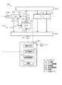
図1には、本実施形態のオイル粘度推定装置である制御装置300を備えるエンジン200におけるオイルの循環経路が図示されている。図1に示すように、エンジン200は、オイルを貯留しているオイルパン201と、オイルパン201内のオイルがオイル供給装置210を介して供給されるメインオイルギャラリ202とを備えている。また、エンジン200には、オイルの供給を必要とする複数のデバイス203が設けられている。そして、デバイス203から排出されたオイルが、オイルパン201に戻るようになっている。
Hereinafter, a first embodiment of an oil viscosity estimating apparatus will be described with reference to FIGS.
FIG. 1 illustrates an oil circulation path in an
オイル供給装置210は、オイルの吐出圧を変更可能なオイルポンプ10と、オイル制御バルブ100とを備えている。そして、制御装置300がオイル制御バルブ100の駆動を制御することで、オイルポンプ10におけるオイルの吐出圧が変更されるようになっている。
The
次に、図1、図2及び図3を参照し、オイルポンプ10について説明する。
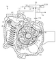
オイルポンプ10は、エンジン200のクランク軸の回転に基づいて駆動する可変容量型のポンプである。図2及び図3に示すように、オイルポンプ10は、クランク軸と同期して回転する入力軸11と、内部に収容空間40が区画されているケーシング部材CSとを備えている。この収容空間40には、入力軸11と一体回転するインナロータ50と、インナロータ50よりも外周側に配置されているアウタロータ60と、アウタロータ60を取り囲むリング状の調整リング70とが設けられている。
Next, the
The
ケーシング部材CSには、その内部にオイルを吸入する吸入ポート12と、内部のオイルをケーシング部材CS外に吐出する吐出ポート13とが設けられている。なお、図1に示すように、吸入ポート12はオイルパン201に通じる吸入油路114に連通しており、吐出ポート13はメインオイルギャラリ202に通じる吐出油路13aに連通している。なお、吐出油路13aには、オイルとともに吐出ポート13から吐出された異物を捕捉するためのフィルタ13bが設けられている。
The casing member CS is provided with a
図2及び図3に示すように、インナロータ50の外周には複数の外歯51が設けられており、アウタロータ60の内周には、インナロータ50の外歯51と噛み合う複数の内歯61が設けられている。内歯61の数は外歯51の数よりも1つ多くなっている。そして、アウタロータ60は、調整リング70によって回転可能に保持されている。
As shown in FIGS. 2 and 3, a plurality of
アウタロータ60の回転中心は、インナロータ50の回転中心に対して偏心している。インナロータ50の外歯51とアウタロータ60の内歯61とは、それらの一部分(図2では右側部分)が互いに噛み合った状態となっている。インナロータ50の外周とアウタロータ60の内周との間には、オイルにより満たされる作動室41が形成されている。
The rotation center of the
作動室41において、インナロータ50の外歯51とアウタロータ60の内歯61とが互いに噛み合う位置から図2に矢印で示す入力軸11の回転方向における所定位置までの部分では、各ロータ50,60の回転に伴ってインナロータ50の外歯51とアウタロータ60の内歯61との間の隙間が徐々に大きくなる。そして、このようにインナロータ50の外歯51とアウタロータ60の内歯61との間の隙間が徐々に大きくなる部分が、吸入ポート12と連通する。一方、作動室41において、ロータ50,60の回転に伴ってインナロータ50の外歯51とアウタロータ60の内歯61との間の隙間が徐々に小さくなる部分が、吐出ポート13と連通する。
In the working
オイルポンプ10が駆動する際には、入力軸11が回転することにより、各ロータ50,60が互いに噛み合いながら回転する。そして、オイルパン201に貯留されているオイルが吸入油路114を介して吸入ポート12から作動室41に吸入され、吐出ポート13から吐出油路13aに吐出される。
When the
調整リング70は、アウタロータ60を保持するリング状の本体部71と、本体部71の外周からロータ50,60の径方向に突出する突出部72とを有している。調整リング70の本体部71には、規定方向に延びる長孔711,712が設けられている。これら長孔711,712には、ケーシング部材CSに固定されているガイドピン81,82が挿通されている。これにより、調整リング70は、長孔711,712の延びる方向に変位可能となっている。
The
調整リング70の突出部72の先端には第1のシール部材83が設けられているとともに、本体部71には第2のシール部材84が設けられている。各シール部材83,84はケーシング部材CSの側壁に当接し、側壁と調整リング70の外周との間の空間がシールされることにより、収容空間40には、調整リング70及び各シール部材83,84によって制御油室42が区画形成されている。
A
制御油室42には、制御油路111と連通する開口部14が設けられており、この制御油路111及び開口部14を通じてオイル制御バルブ100から制御油室42にオイルが供給可能となっている。また、収容空間40には、制御油室42の容積を小さくする方向への付勢力を突出部72に付与するスプリング15が設けられている。このスプリング15は、突出部72を挟んだ制御油室42の反対側に配設されている。図2には、制御油室42の内圧が低いため、スプリング15からの付勢力によって、制御油室42の容積が最小となる位置で調整リング70が保持されている状態が示されている。なお、本実施形態では、このように制御油室42の容積が最小となるときの調整リング70の位置、すなわち図2での調整リング70の位置を、「初期位置」というものとする。
The
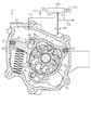
そして、調整リング70が初期位置に配置されている状況下で、制御油室42にオイルが供給され、制御油室42の内圧が高くなると、スプリング15からの付勢力に抗し、制御油室42の容積を大きくする方向に初期位置から調整リング70が変位する。すなわち、図2に示す状態から図3に示す状態に向かう方向(図2における反時計回り方向)に調整リング70が回動しながら変位する。一方、オイル制御バルブ100の駆動によって制御油室42からオイルが排出されるようになると、制御油室42の内圧が低くなり、スプリング15からの付勢力によって、制御油室42の容積を小さくする方向に調整リング70が変位する。すなわち、図3に示す状態から図2に示す状態に向かう方向(図3における時計回り方向)に調整リング70が回動しながら変位する。つまり、調整リング70の位置は、制御油室42の内圧とスプリング15からの付勢力とによって決まる。そして、調整リング70の位置の変化によって、吸入ポート12及び吐出ポート13の各々の開口に対するインナロータ50及びアウタロータ60の歯51,61の噛み合う部分の相対的な位置が変化する。このため、制御油室42の内圧の調整による調整リング70の位置の変更を通じ、入力軸11の一回転あたりの吐出ポート13からのオイルの吐出量、すなわち吐出ポート13から吐出されるオイルの圧力である吐出圧が変更される。
When the
具体的には、オイルポンプ10では、図2に示されているように調整リング70の位置が「初期位置」にあるときに、オイルの吐出圧が最大になる。図2に示すようにオイルの吐出圧が最大となる位置にある状態から制御油室42の内圧が高くなると、内圧の上昇に伴い、調整リング70が、スプリング15からの付勢力に抗して図2における反時計回り方向に回動しながら変位する。その結果、ロータ50,60の回転に伴って外歯51と内歯61との間の隙間が徐々に大きくなる部分のうち、吸入ポート12と重なる範囲が小さくなるとともに、外歯51と内歯61との間の隙間が徐々に小さくなる部分の一部が吸入ポート12と重なるようになる。その結果、オイルの吐出圧が低くなる。反対に、制御油室42の内圧が低くなると、内圧の低下に伴い、調整リング70が、スプリング15からの付勢力によって図3における時計回り方向に回動しながら変位し、オイルの吐出圧が高くなる。
Specifically, in the
次に、図1、図2及び図3を参照し、オイル制御バルブ100について説明する。
図1及び図2に示すように、オイル制御バルブ100は、電磁駆動式のアクチュエータ100Aの駆動によってスプールの位置を切り替えることにより複数の油路の連通状態を切り替えることができる。すなわち、オイル制御バルブ100は、制御油路111が接続される制御ポート101と、オイルポンプ10の吐出油路13aから分岐する供給油路112が接続される供給ポート102と、オイルを排出するための排出油路113が接続される排出ポート103とを備えている。そして、アクチュエータ100Aに対する指示電流値Iocvの調整によって、同スプールの位置が、制御ポート101に還流してきたオイルを排出ポート103から排出する排出位置(図2)と、供給ポート102に供給されるオイルを制御ポート101から制御油路111に送り出す供給位置(図3)との間で変わるようになっている。すなわち、本実施形態では、アクチュエータ100Aに入力する指示電流値Iocvが大きくなるにつれて、スプールが排出位置から供給位置に向けて変位するようになる。このように排出位置から供給位置に向けてスプールを変位させることで、オイルポンプ10の制御油室42の内圧を高くすることができる、すなわちオイルポンプ10におけるオイルの吐出圧を低くすることができる。
Next, the
As shown in FIGS. 1 and 2, the
次に、図1を参照し、制御装置300について説明する。
図1に示すように、制御装置300には、吐出圧センサ311と、温度センサ312と、クランク角センサ313とが電気的に接続されている。吐出圧センサ311は、吐出油路13aにおけるフィルタ13bよりも下流側に配置されており、フィルタ13bを通過したオイルの圧力である吐出圧センサ値PSを検出する。また、温度センサ312はオイルポンプ10に供給されるオイルの温度である油温TMPを検出し、クランク角センサ313はエンジン200のクランク軸の回転速度であるエンジン回転速度NEを検出する。そして、制御装置300は、これら各センサ311〜313によって検出された情報を基に、オイル供給装置210の作動を制御するようになっている。
Next, the
As shown in FIG. 1, a
また、制御装置300は、オイルポンプ10におけるオイルの吐出圧を制御したり、オイルの粘度を推定したりするための機能部として、目標圧設定部301、吐出圧制御部302、応答時間取得部303及び処理部304を有している。
The
目標圧設定部301は、オイルポンプ10におけるオイルの吐出圧の目標値である目標吐出圧PTrの導出を行っている。そして、目標圧設定部301は、導出した目標吐出圧PTrを吐出圧制御部302及び応答時間取得部303に出力する。
The target
吐出圧制御部302は、目標圧設定部301から入力された目標吐出圧PTrと吐出圧センサ値PSとを用いたフィードバック制御に基づいて指示電流値Iocvを算出し、この指示電流値Iocvをアクチュエータ100Aに入力することで、制御油室42の内圧、すなわちオイルポンプ10におけるオイルの吐出圧を制御する。具体的には、吐出圧制御部302は、以下に示す関係式(式1)を用いて指示用目標吐出圧PTrAを算出し、この指示用目標吐出圧PTrAに対応する指示電流値Iocvを求める。すなわち、指示電流値Iocvは、指示用目標吐出圧PTrAが低いほど大きくなる。なお、関係式(式1)において、「X」はフィードバック制御の比例項であり、「Y」はフィードバック制御の積分項である。また、「G」は共通のゲインであり、ゲインGはオイルの粘度に応じた値に設定される。
The discharge
PTrA=(PTr+X+Y)×G ・・・(式1)
応答時間取得部303は、規定条件の成立時点から、吐出圧センサ値PSが目標吐出圧PTrに収束するまでに要する時間である応答時間TMを取得する。規定条件とは、吐出圧センサ値PSが目標吐出圧PTrよりも小さいと判定するための条件のことであり、その詳細については後述する。そして、応答時間取得部303は、取得した応答時間TMを処理部304に出力する。
PTrA = (PTr + X + Y) × G (Formula 1)
The response
処理部304は、応答時間取得部303から入力された応答時間TMに基づきオイルの粘度を推定し、その推定結果に応じた処理を行う。具体的には、処理部304は、応答時間TMから推定されるオイルの粘度が極端に低いときには、未燃燃料のオイルへの混入量が多く、オイル交換が必要なほどにオイルの希釈が進行していると判定し、オイル交換を促す報知処理を行う。また、処理部304は、オイル交換が必要なほどにオイルの希釈が進行していると判定していない場合、オイル供給装置210で使用されているオイル粘度の推定値を基に、オイルポンプ10の作動を制御するためのパラメータである上記ゲインGを補正する。
The
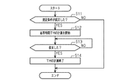
次に、図4を参照し、応答時間TMを取得するために応答時間取得部303が実行する処理ルーチンについて説明する。この処理ルーチンは、吐出圧センサ値PSが目標吐出圧PTrに収束している定常状態から吐出圧センサ値PSが目標吐出圧PTrに収束していない非定常状態に移行したときに実行される。
Next, a processing routine executed by the response
図4に示すように、本処理ルーチンにおいて、応答時間取得部303は、規定条件が成立したかを判定する(ステップS11)。本実施形態では、規定条件を、目標吐出圧PTrの単位時間あたりの増大量IPTrが増大量判定値IPTrTh以上であることと、エンジン回転速度NEの単位時間あたりの減少量DNEが減少量判定値DNETh以上であることと、の論理和としている。ここでいう「単位時間」とは、上記フィードバック制御の実行周期の時間の長さと等しい。なお、増大量判定値IPTrThは、「目標変化判定値」の一例であり、増大量IPTrが増大量判定値IPTrTh以上である場合に、目標吐出圧PTrが変更されたために吐出圧センサ値PSと目標吐出圧PTrとの差分が大きくなったと判定できるような値に設定されている。また、減少量判定値DNEThは、「回転変化判定値」の一例であり、減少量DNEが減少量判定値DNETh以上である場合に、エンジン回転速度NEが減少したために吐出圧センサ値PSと目標吐出圧PTrとの差分が大きくなったと判定できるような値に設定されている。
As shown in FIG. 4, in the present processing routine, the response
そして、規定条件が成立した場合には、目標吐出圧PTrが吐出圧センサ値PSと相違していると判定する。一方、規定条件が成立していない場合には、定常状態から非定常状態に移行していても、目標吐出圧PTrが吐出圧センサ値PSと相違しているとは判定しない。 When the specified condition is satisfied, it is determined that the target discharge pressure PTr is different from the discharge pressure sensor value PS. On the other hand, when the specified condition is not satisfied, it is not determined that the target discharge pressure PTr is different from the discharge pressure sensor value PS even if the steady state is shifted to the unsteady state.
そのため、規定条件が成立している場合(ステップS11:YES)、応答時間取得部303は、上記応答時間TMの計測を開始する(ステップS12)。そして、応答時間取得部303は、吐出圧センサ値PSが目標吐出圧PTrに収束したか否かを判定する(ステップS13)。未だ収束していない場合(ステップS13:NO)、応答時間取得部303は、吐出圧センサ値PSが目標吐出圧PTrに収束するまでステップS13の判定処理を繰り返す。一方、既に収束している場合(ステップS13:YES)、応答時間取得部303は、応答時間TMの計測を終了し(ステップS14)、本処理ルーチンを終了する。
Therefore, when the specified condition is satisfied (step S11: YES), the response
その一方で、ステップS11において、規定条件が成立していない場合(NO)、応答時間取得部303は、本処理ルーチンを終了する。つまり、規定条件が成立していない場合、すなわち定常状態から非定常状態に移行しても吐出圧センサ値PSと目標吐出圧PTrとの差分が小さいときには、応答時間TMが取得されない。
On the other hand, if the prescribed condition is not satisfied in step S11 (NO), the response
次に、図5を参照し、応答時間取得部303によって応答時間TMが取得されたことを契機に処理部304が実行する処理ルーチンについて説明する。
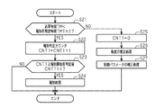
図5に示すように、本処理ルーチンにおいて、処理部304は、応答時間取得部303から入力された応答時間TMが報知用判定時間TMTh1未満であるか否かを判定する(ステップS21)。
Next, a processing routine executed by the
As shown in FIG. 5, in this processing routine, the
オイルへの未燃燃料の混入によってオイルが希釈されると、オイルの粘度が低くなり、応答時間TMが短くなる。そのため、オイルへの未燃燃料の混入量が多くなってオイルの希釈が進むと、オイルの粘度が極端に低くなるため、応答時間TMが極端に短くなる。このようにオイルが希釈されてオイルの粘度が極端に低くなったときには、オイル交換が必要となる。そこで、本実施形態では、オイルの希釈が進行したためにオイルの粘度が極端に低くなったか否かを判定するための判定値として、報知用判定時間TMTh1が設定されている。そして、応答時間TMが報知用判定時間TMTh1未満であるときには、オイル交換が必要なほどにオイルの希釈が進行した可能性があると判定する。一方、応答時間TMが報知用判定時間TMTh1以上であるときには、オイル交換が必要なほどにはオイルの希釈が進行していないと判定する。 When the oil is diluted by mixing unburned fuel into the oil, the viscosity of the oil is lowered and the response time TM is shortened. For this reason, when the amount of unburned fuel mixed in the oil increases and the dilution of the oil proceeds, the viscosity of the oil becomes extremely low, and the response time TM becomes extremely short. When the oil is diluted as described above and the viscosity of the oil becomes extremely low, it is necessary to change the oil. Therefore, in this embodiment, the notification determination time TMTh1 is set as a determination value for determining whether or not the viscosity of the oil has become extremely low due to the progress of oil dilution. Then, when the response time TM is less than the notification determination time TMTh1, it is determined that there is a possibility that oil dilution has progressed to the extent that oil replacement is necessary. On the other hand, when the response time TM is equal to or longer than the notification determination time TMTh1, it is determined that the oil dilution has not progressed to the extent that oil replacement is necessary.
そのため、応答時間TMが報知用判定時間TMTh1未満である場合(ステップS21:YES)、処理部304は、報知判定カウンタCNT1を「1」インクリメントする(ステップS22)。この報知判定カウンタCNT1は、応答時間TMが報知用判定時間TMTh1未満になることの連続回数のことである。そして、処理部304は、更新した報知判定カウンタCNT1が報知開始用判定値CNTTh1以上であるか否かを判定する(ステップS23)。報知開始用判定値CNTTh1は、「2」以上の整数(例えば、4)に設定されている。そして、報知判定カウンタCNT1が報知開始用判定値CNTTh1以上になったときには、オイル交換が必要なほどにオイルの希釈化が進行したと判定する。
Therefore, when the response time TM is less than the notification determination time TMTh1 (step S21: YES), the
そのため、報知判定カウンタCNT1が報知開始用判定値CNTTh1以上である場合(ステップS23:YES)、処理部304は、オイル交換を促す報知処理を行う(ステップS24)。すなわち、本実施形態では、応答時間TMが報知用判定時間TMTh1未満であることを条件に報知処理が行われるようになっている。その後、処理部304は、本処理ルーチンを終了する。一方、報知判定カウンタCNT1が報知開始用判定値CNTTh1未満である場合(ステップS23:NO)、処理部304は、報知処理を行うことなく、本処理ルーチンを終了する。
Therefore, when the notification determination counter CNT1 is greater than or equal to the notification start determination value CNTTh1 (step S23: YES), the
その一方で、ステップS21において、応答時間TMが報知用判定時間TMTh1以上である場合(NO)、処理部304は、報知判定カウンタCNT1を「0」にリセットする(ステップS25)。そして、処理部304は、オイル供給装置210で使用されているオイルの粘度を推定する推定処理を行う(ステップS26)。すなわち、この推定処理では、処理部304は、応答時間TMが短いほどオイルの粘度が低いと推定する。続いて、処理部304は、推定したオイルの粘度を基に、オイルポンプ10におけるオイルの吐出圧を制御するために用いられる制御パラメータの補正処理を行う(ステップS27)。例えば、処理部304は、補正処理では、フィードバック制御のパラメータの一例である上記関係式(式1)のゲインGを、推定したオイルの粘度に応じて補正する。その後、処理部304は、本処理ルーチンを終了する。
On the other hand, when the response time TM is equal to or longer than the notification determination time TMTh1 in step S21 (NO), the
次に、図6を参照し、定常状態から非定常状態に移行したときに規定条件が成立した場合の作用を効果とともに説明する。なお、図6において、破線は、未燃燃料がオイルに混入していない場合における吐出圧センサ値PSの推移を表している一方、太い実線は、未燃燃料がオイルに混入しており、オイル交換が必要なほどにオイルの希釈が進行している場合における吐出圧センサ値PSの推移を表している。 Next, referring to FIG. 6, an explanation will be given of the operation when the prescribed condition is satisfied when the steady state is shifted to the unsteady state, together with the effects. In FIG. 6, the broken line represents the change in the discharge pressure sensor value PS when unburned fuel is not mixed in the oil, while the thick solid line represents unburned fuel mixed in the oil. It shows the transition of the discharge pressure sensor value PS when the dilution of oil is progressing to the extent that replacement is necessary.
吐出油路13aに配置されているフィルタ13bで異物が捕捉されると、吐出油路13aにおける吐出圧センサ311よりも上流側で圧力損失が大きくなる。この場合、吐出油路13aのうち、フィルタ13bよりも上流側とフィルタ13bよりも下流側との間では、圧力損失の大きさに相当する差圧が発生する。このように差圧が発生している状況下で、オイルポンプ10におけるオイルの吐出圧を増大させる場合、上記差圧が維持されるかたちで、吐出油路13aにおけるフィルタ13bよりも上流側の油圧及びフィルタ13bよりも下流側の油圧の双方が高くなる。そのため、吐出圧センサ値PSを目標吐出圧PTrに向けて増大させる際の吐出圧センサ値PSの増大速度は、上記圧力損失によって左右されにくい。したがって、オイルの粘度が低いほど、吐出圧センサ値SPが目標吐出圧PTrに収束するまでに要する時間は短くなる。すなわち、応答時間TMの長さも、上記圧力損失によって左右されにくい。
When foreign matter is captured by the
本実施形態では、定常状態から非定常状態に移行したときに、規定条件が成立した場合、規定条件の成立時点から、吐出圧センサ値PSが目標吐出圧PTrに収束するまでの時間である応答時間TMが取得される。そして、この応答時間TMが短いほど、オイル供給装置210で使用されているオイルの粘度が低いと推定される。このように吐出油路13aにおける吐出圧センサ311よりも上流側での圧力損失の変化に左右されにくい応答時間TMを基にオイル粘度を推定することにより、当該圧力損失の変化による影響を抑制した態様でオイルの粘度を推定することができる。
In the present embodiment, when the specified condition is satisfied when the steady state is changed to the unsteady state, the response is a time from when the specified condition is satisfied until the discharge pressure sensor value PS converges to the target discharge pressure PTr. Time TM is acquired. And it is estimated that the viscosity of the oil currently used with the
また、本実施形態では、定常状態から非定常状態に移行した場合において、吐出圧センサ値PSと目標吐出圧PTrとの差分が大きいほど、オイルの粘度が高い場合と低い場合とで、取得される応答時間TMの差が出やすい。そのため、定常状態から非定常状態に移行した際に、目標吐出圧PTrの単位時間あたりの増大量IPTrが増大量判定値IPTrTh以上であること、及び、エンジン回転速度NEの単位時間あたりの減少量DNEが減少量判定値DNETh以上であることの少なくとも1つの条件が成立し、規定条件が成立したときに限って、応答時間TMの取得を行うようにしている。そして、このようなときに取得した応答時間TMを用いてオイル粘度を推定することにより、オイルの粘度を精度良く推定することができる。 Further, in the present embodiment, when the transition from the steady state to the unsteady state is performed, the difference between the discharge pressure sensor value PS and the target discharge pressure PTr is acquired as the oil viscosity is high or low. Difference in response time TM is likely to occur. Therefore, when the transition from the steady state to the unsteady state is performed, the increase amount IPTr per unit time of the target discharge pressure PTr is equal to or greater than the increase amount determination value IPTrTh, and the decrease amount per unit time of the engine speed NE. The response time TM is acquired only when at least one condition that DNE is equal to or greater than the decrease amount determination value DNETh is satisfied and the specified condition is satisfied. And by estimating the oil viscosity using the response time TM acquired at such time, the viscosity of the oil can be estimated with high accuracy.
例えば、図6に示すように、第1のタイミングt11で、目標吐出圧PTrが大きくなる。目標吐出圧PTrの単位時間あたりの増大量IPTrが増大量判定値IPTrThよりも大きいと、規定条件が成立する。このとき、オイルが希釈していない場合、図6に破線で示すように、第4のタイミングt14で、吐出圧センサ値PSが目標吐出圧PTrに収束し、非定常状態から定常状態に移行する。この第4のタイミングt14は、第1のタイミングt11から報知用判定時間TMTh1が経過した第3のタイミングt13よりもあとのタイミングである。そのため、報知判定カウンタCNT1は「0」のままである。 For example, as shown in FIG. 6, the target discharge pressure PTr increases at the first timing t11. If the increase amount IPTr per unit time of the target discharge pressure PTr is larger than the increase amount determination value IPTrTh, the specified condition is satisfied. At this time, if the oil is not diluted, the discharge pressure sensor value PS converges to the target discharge pressure PTr at the fourth timing t14 as shown by a broken line in FIG. 6 and shifts from the unsteady state to the steady state. . The fourth timing t14 is a timing after the third timing t13 when the notification determination time TMTh1 has elapsed from the first timing t11. Therefore, the notification determination counter CNT1 remains “0”.
油温TMPが同一温度という条件下では、オイルに混合される未燃燃料の量が徐々に多くなり、オイルの希釈化が進むにつれてオイルの粘度が徐々に低くなる。そのため、オイルの希釈化が進むにつれて、規定条件が成立して吐出圧センサ値PSを目標吐出圧PTrに収束させる際に取得される応答時間TMが徐々に短くなる。 Under the condition that the oil temperature TMP is the same temperature, the amount of unburned fuel mixed with the oil gradually increases, and the viscosity of the oil gradually decreases as the dilution of the oil proceeds. Therefore, as the oil dilution progresses, the response time TM acquired when the specified condition is satisfied and the discharge pressure sensor value PS converges to the target discharge pressure PTr gradually decreases.
そして、このように取得される応答時間TMが短くなると、オイルの粘度が低くなったと推定できるため、応答時間TMに基づいたオイルの粘度の推定値によって、フィードバック制御のパラメータが補正される。したがって、オイルの希釈化によってオイルの粘度が低くなっても、現時点のオイル粘度に応じたオイルポンプ10の作動制御を行うことができる。
When the response time TM acquired in this way is shortened, it can be estimated that the viscosity of the oil has decreased, and therefore the feedback control parameter is corrected by the estimated value of the viscosity of the oil based on the response time TM. Therefore, even if the oil viscosity becomes low due to the dilution of the oil, the operation of the
そして、未燃燃料のオイルへの混入量が増えてオイルの希釈がさらに進行した場合、規定条件が成立したときに取得される応答時間TMが極端に短くなる。そして、図6に太い実線で示すように第3のタイミングt13よりも前の第2のタイミングt12で吐出圧センサ値PSが目標吐出圧PTrに収束するようになると、オイル交換が必要なほどにオイルの希釈が進行している可能性があると判定できるため、報知判定カウンタCNT1が更新される。そして、報知判定カウンタCNT1が報知開始用判定値CNTTh1以上になったときには、報知処理によってオイル交換が促される。すなわち、オイル交換が必要なほどにオイルの希釈化が進行したときに、オイル交換を促すことができる。 And when the amount of unburned fuel mixed into the oil increases and the dilution of the oil further proceeds, the response time TM acquired when the prescribed condition is satisfied becomes extremely short. When the discharge pressure sensor value PS converges to the target discharge pressure PTr at the second timing t12 prior to the third timing t13 as shown by a thick solid line in FIG. 6, the oil needs to be changed. Since it can be determined that there is a possibility that oil dilution is in progress, the notification determination counter CNT1 is updated. When the notification determination counter CNT1 becomes equal to or greater than the notification start determination value CNTTh1, oil replacement is prompted by notification processing. That is, when oil dilution has progressed to such an extent that oil replacement is necessary, oil replacement can be promoted.
(第2の実施形態)
次に、オイル粘度推定装置の第2の実施形態を図7に従って説明する。第2の実施形態では、応答時間TMを元に取得したオイル粘度の推定値を用い、オイルの種類を推定する点などが第1の実施形態と相違している。そこで、以下の説明においては、第1の実施形態と相違している部分について主に説明するものとし、第1の実施形態と同一又は相当する部材構成には同一符号を付して重複説明を省略するものとする。
(Second Embodiment)
Next, a second embodiment of the oil viscosity estimating apparatus will be described with reference to FIG. The second embodiment is different from the first embodiment in that the estimated value of the oil viscosity obtained based on the response time TM is used to estimate the type of oil. Therefore, in the following description, parts different from those of the first embodiment will be mainly described, and the same or corresponding member configurations as those of the first embodiment are denoted by the same reference numerals, and redundant description will be given. Shall be omitted.
次に、図7を参照し、応答時間取得部303によって応答時間TMが取得されたことを契機に処理部304が実行する処理ルーチンについて説明する。
図7に示すように、本処理ルーチンにおいて、処理部304は、応答時間取得部303から入力された応答時間TMが判別用判定時間TMTh2未満であるか否かを判定する(ステップS31)。
Next, a processing routine executed by the
As shown in FIG. 7, in the present processing routine, the
粘度の低い種類のオイルをオイル供給装置210で使用している状況下において、オイルポンプ10におけるオイルの吐出圧を高くするときには、粘度の高い種類のオイルをオイル供給装置210で使用している場合と比較して吐出圧センサ値PSの増大速度が高くなる。そのため、粘度の低い種類のオイルを使用している場合ほど、定常状態から非定常状態に移行した時点から吐出圧センサ値PSが目標吐出圧PTrに収束するまでに要する時間、すなわち応答時間TMが短くなる。すなわち、応答時間TMを基に、オイル供給装置210で使用しているオイルの種類を推定することができる。
In a situation where a low viscosity type oil is used in the
そこで、本実施形態では、オイル供給装置210で使用されるオイルの純正品の応答性に応じた判定時間として、判別用判定時間TMTh2が設定されている。オイルの粘度は油温TMPが高いほど低くなる。そのため、本実施形態では、判別用判定時間TMTh2を、油温TMPが高いほど短くしている。そして、応答時間取得部303から入力された応答時間TMが判別用判定時間TMTh2未満であるときには、純正品よりも粘度の低い種類のオイルがオイル供給装置210で使用されている可能性があると判定する。一方、応答時間TMが判別用判定時間TMTh2以上であるときには、純正品よりも粘度の低い種類のオイルがオイル供給装置210で使用されている可能性があると判定しない。
Therefore, in the present embodiment, the determination time TMTh2 is set as the determination time according to the responsiveness of the genuine oil used in the
そのため、応答時間TMが判別用判定時間TMTh2以上である場合(ステップS31:NO)、処理部304は、後述する油種推定カウンタCNT2を「0」にリセットする(ステップS32)。その後、処理部304は、本処理ルーチンを終了する。一方、応答時間TMが判別用判定時間TMTh2未満である場合(ステップS31:YES)、処理部304は、油種推定カウンタCNT2を「1」インクリメントする(ステップS33)。この油種推定カウンタCNT2は、応答時間TMが判別用判定時間TMTh2未満になることの連続回数のことである。
Therefore, when the response time TM is equal to or greater than the determination time TMTh2 (step S31: NO), the
そして、処理部304は、更新した油種推定カウンタCNT2が油種推定開始用判定値CNTTh2以上であるか否かを判定する(ステップS34)。油種推定開始用判定値CNTTh2は、「2」以上の整数(例えば、4)に設定されている。そして、油種推定カウンタCNT2が油種推定開始用判定値CNTTh2以上であるときには、純正品よりも粘度の低い種類のオイルがオイル供給装置210で使用されていると判定する。一方、油種推定カウンタCNT2が油種推定開始用判定値CNTTh2未満であるときには、純正品よりも粘度の低い種類のオイルがオイル供給装置210で使用されていると判定しない。
Then, the
そのため、油種推定カウンタCNT2が油種推定開始用判定値CNTTh2未満である場合(ステップS34:NO)、処理部304は、本処理ルーチンを終了する。一方、油種推定カウンタCNT2が油種推定開始用判定値CNTTh2以上である場合(ステップS34:YES)、処理部304は、油種の推定処理を行う(ステップS35)。すなわち、油種の推定処理では、処理部304は、応答時間TMに加え、温度センサ312によって検出されている油温TMPも用いて油種を推定する。例えば、処理部304は、応答時間TMが短いほどオイル粘度の推定値を低くする。このとき、処理部304は、油温TMPが高いほどオイル粘度の推定値が高くなるように、応答時間TMを基に算出したオイル粘度の推定値を油温TMPを用いて補正する。そして、処理部304は、補正後のオイル粘度の推定値を基に、オイル供給装置210で使用されているオイルの種類を推定する。すなわち、処理部304は、オイルの粘度とオイルの種類とを関連付けたマップを有しており、当該マップを用い、オイル粘度の推定値に対応するオイルの種類を導出する。
Therefore, when the oil type estimation counter CNT2 is less than the oil type estimation start determination value CNTTh2 (step S34: NO), the
続いて、処理部304は、推定したオイルの種類を基に、オイルポンプ10におけるオイルの吐出圧を制御するために用いられる制御パラメータの補正処理を行う(ステップS36)。例えば、処理部304は、補正処理では、フィードバック制御のパラメータの一例である上記関係式(式1)のゲインGを、推定したオイルの種類に応じて補正する。その後、処理部304は、本処理ルーチンを終了する。
Subsequently, the
次に、純正品よりも粘度の低い種類のオイルがオイル供給装置210で使用されている場合の作用を効果とともに説明する。
定常状態から非定常状態に移行したときに、規定条件が成立した場合、規定条件の成立時点から、吐出圧センサ値PSが目標吐出圧PTrに収束するまでの時間である応答時間TMが取得される。純正品よりも粘度の低い種類のオイルがオイル供給装置210で使用されているため、取得される応答時間TMは、純正品がオイル供給装置210で使用されている場合よりも短くなる。このとき、応答時間TMが判別用判定時間TMTh2未満であると油種推定カウンタCNT2が更新される。
Next, the operation in the case where a kind of oil having a viscosity lower than that of a genuine product is used in the
When the specified condition is satisfied when the steady state is changed to the unsteady state, a response time TM that is a time from when the specified condition is satisfied until the discharge pressure sensor value PS converges to the target discharge pressure PTr is acquired. The Since a kind of oil having a viscosity lower than that of the genuine product is used in the
そして、油種推定カウンタCNT2が油種推定開始用判定値CNTTh2以上になったときには油種の推定処理が行われる。そして、この推定処理の結果に基づいてフィードバック制御のパラメータが補正される。したがって、純正品よりも低粘度の種類のオイルがオイル供給装置210で使用されるようになった場合でも、油種に応じたオイルポンプ10の作動制御を行うことができる。
When the oil type estimation counter CNT2 becomes equal to or greater than the oil type estimation start determination value CNTTh2, the oil type estimation process is performed. Then, the feedback control parameters are corrected based on the result of the estimation process. Therefore, even when oil having a lower viscosity than that of a genuine product is used in the
なお、上記各実施形態は以下のような別の実施形態に変更してもよい。
・吐出圧センサ値PSが目標吐出圧PTrよりも大きいときに、規定条件が成立するようにし、規定条件が成立したと判定した時点から吐出圧センサ値PSが目標吐出圧PTrに収束するまでの時間を応答時間TMとして取得するようにしてもよい。この場合であっても、応答時間TMは、オイル粘度が低いほど短くなるとともに、吐出油路13aにおけるフィルタ13bよりも上流側での圧力損失の大きさに左右されにくい。したがって、このように取得した応答時間TMを用いてオイル粘度を推定することによって、吐出油路13aにおけるフィルタ13bよりも上流側で圧力損失が高くなってもオイル粘度の推定精度の低下を抑制することができる。
In addition, you may change each said embodiment into another embodiment as follows.
When the discharge pressure sensor value PS is larger than the target discharge pressure PTr, the specified condition is satisfied, and from when it is determined that the specified condition is satisfied, until the discharge pressure sensor value PS converges to the target discharge pressure PTr. You may make it acquire time as response time TM. Even in this case, the response time TM becomes shorter as the oil viscosity is lower, and is less susceptible to the magnitude of the pressure loss upstream of the
この場合、規定条件は、例えば、目標吐出圧PTrの単位時間あたりの減少量DPTrが減少量判定値DPTrTh以上であることと、エンジン回転速度NEの単位時間あたりの増大量INEが増大量判定値INETh以上であることと、の論理和とすればよい。この場合、減少量判定値DPTrThが「目標変化判定値」に相当し、増大量判定値INEThが「回転変化判定値」に相当する。 In this case, the specified conditions are, for example, that the decrease amount DPTr per unit time of the target discharge pressure PTr is equal to or greater than the decrease amount determination value DPTrTh, and the increase amount INE per unit time of the engine rotation speed NE is the increase amount determination value. What is necessary is just to be the logical sum of being more than INETh. In this case, the decrease amount determination value DPTrTh corresponds to the “target change determination value”, and the increase amount determination value INETh corresponds to the “rotation change determination value”.
・上記実施形態では、オイル供給装置210は、オイルポンプ10としてギヤポンプを備えている。しかし、オイル供給装置210は、ギヤポンプ以外の他の種類のポンプ(例えば、ベーンポンプ)をオイルポンプ10として備えた構成であってもよい。
In the above embodiment, the
・オイルポンプは、機関駆動式のポンプではなく、電動式のポンプであってもよい。この場合、電動モータの回転速度、すなわち電動モータに対する指示電流値を調整することによってオイルポンプにおけるオイルの吐出圧を制御することができる。このような電動式のオイルポンプを備えるオイル供給装置では、目標吐出圧PTrが小さくなったり大きくなったりすると、規定条件が成立することがある。こうしたオイル供給装置でも、規定条件の成立時点から吐出圧センサ値PSが目標吐出圧PTrに収束するまでの時間である応答時間TMを用いることで、オイル粘度を精度良く推定することができる。 The oil pump may be an electric pump instead of an engine driven pump. In this case, the oil discharge pressure in the oil pump can be controlled by adjusting the rotation speed of the electric motor, that is, the instruction current value for the electric motor. In the oil supply apparatus including such an electric oil pump, the specified condition may be satisfied when the target discharge pressure PTr decreases or increases. Even in such an oil supply device, the oil viscosity can be accurately estimated by using the response time TM that is the time from when the prescribed condition is satisfied until the discharge pressure sensor value PS converges to the target discharge pressure PTr.
なお、このような電動式のオイルポンプを備えるオイル供給装置では、電動モータの回転速度は、エンジン回転速度NEとは同期していない。そのため、エンジン回転速度NEが高くなっても、電動モータの回転速度が変化しない限り規定条件が成立することはない。 In the oil supply device including such an electric oil pump, the rotation speed of the electric motor is not synchronized with the engine rotation speed NE. Therefore, even if the engine rotational speed NE increases, the prescribed condition is not satisfied unless the rotational speed of the electric motor changes.
10…オイルポンプ、11…入力軸、13a…吐出油路、200…エンジン、210…オイル供給装置、300…制御装置、303…応答時間取得部、304…処理部、311…吐出圧センサ。
DESCRIPTION OF
Claims (6)
前記目標吐出圧が前記吐出圧センサ値と相違していると判定できる規定条件の成立時点から前記吐出圧センサ値が前記目標吐出圧に収束するまでに要する時間である応答時間を取得する応答時間取得部と、
取得された前記応答時間が短いほど、オイルの粘度が低いと推定する処理部と、を備える
オイル粘度推定装置。 An oil pump capable of changing an oil discharge pressure, a discharge oil passage through which oil discharged from the oil pump flows, and a sensor that detects a pressure of oil flowing through the discharge oil passage, and discharge to the oil pump Applied to an oil supply device in which the operation of the oil pump is controlled so that a discharge pressure sensor value that is the pressure of oil detected by the sensor converges to a target discharge pressure that is a target value of pressure,
A response time for obtaining a response time that is a time required for the discharge pressure sensor value to converge to the target discharge pressure from a point in time when a prescribed condition that can determine that the target discharge pressure is different from the discharge pressure sensor value is satisfied An acquisition unit;
And a processing unit that estimates that the viscosity of the oil is lower as the acquired response time is shorter.
請求項1に記載のオイル粘度推定装置。 The oil viscosity estimation apparatus according to claim 1, wherein the specified condition includes that a change amount per unit time of the target discharge pressure is equal to or greater than a target change determination value.
前記規定条件は、エンジン回転速度の単位時間あたりの変化量が回転変化判定値以上であることを含む
請求項1に記載のオイル粘度推定装置。 The oil pump has an input shaft that rotates in synchronization with the rotation of the crankshaft of the engine, and is a pump capable of operating an oil discharge amount per one rotation of the input shaft,
The oil viscosity estimation apparatus according to claim 1, wherein the prescribed condition includes that a change amount per unit time of the engine rotation speed is equal to or greater than a rotation change determination value.
請求項1〜請求項3のうち何れか一項に記載のオイル粘度推定装置。 The said process part performs the alerting | reporting process which urges oil change on the condition that the said response time acquired by the said response time acquisition part is less than the determination time for alerting | reporting. The oil viscosity estimation apparatus according to item.
請求項4に記載のオイル粘度推定装置。 The processing unit operates the oil pump to converge the discharge pressure sensor value to the target discharge pressure on the condition that the response time acquired by the response time acquisition unit is equal to or longer than the notification determination time. The oil viscosity estimation device according to claim 4, wherein a parameter for controlling the pressure is made equal to a value corresponding to the viscosity of the oil estimated from the response time.
請求項1〜請求項3のうち何れか一項に記載のオイル粘度推定装置。 The processing unit is of a type having a lower viscosity than the case where the response time is equal to or greater than the determination time for determination on condition that the response time acquired by the response time acquisition unit is less than the determination time for determination. Estimated that oil is being discharged from the oil pump, and the parameter for controlling the operation of the oil pump to converge the discharge pressure sensor value to the target discharge pressure is a value corresponding to a low viscosity type oil The oil viscosity estimation apparatus according to any one of claims 1 to 3.
Priority Applications (1)
| Application Number | Priority Date | Filing Date | Title |
|---|---|---|---|
| JP2017014767A JP2018123714A (en) | 2017-01-30 | 2017-01-30 | Oil viscosity estimation device |
Applications Claiming Priority (1)
| Application Number | Priority Date | Filing Date | Title |
|---|---|---|---|
| JP2017014767A JP2018123714A (en) | 2017-01-30 | 2017-01-30 | Oil viscosity estimation device |
Publications (1)
| Publication Number | Publication Date |
|---|---|
| JP2018123714A true JP2018123714A (en) | 2018-08-09 |
Family
ID=63109493
Family Applications (1)
| Application Number | Title | Priority Date | Filing Date |
|---|---|---|---|
| JP2017014767A Pending JP2018123714A (en) | 2017-01-30 | 2017-01-30 | Oil viscosity estimation device |
Country Status (1)
| Country | Link |
|---|---|
| JP (1) | JP2018123714A (en) |
Cited By (1)
| Publication number | Priority date | Publication date | Assignee | Title |
|---|---|---|---|---|
| CN116106173A (en) * | 2023-04-07 | 2023-05-12 | 天津索克汽车试验有限公司 | Engine oil viscosity measurement method for new energy automobile |
-
2017
- 2017-01-30 JP JP2017014767A patent/JP2018123714A/en active Pending
Cited By (1)
| Publication number | Priority date | Publication date | Assignee | Title |
|---|---|---|---|---|
| CN116106173A (en) * | 2023-04-07 | 2023-05-12 | 天津索克汽车试验有限公司 | Engine oil viscosity measurement method for new energy automobile |
Similar Documents
| Publication | Publication Date | Title |
|---|---|---|
| JP4606425B2 (en) | Pump system control method and demand flow system | |
| JP5898107B2 (en) | Control unit for variable displacement oil pump | |
| JP2009167811A (en) | Valve timing adjusting device | |
| JP6885812B2 (en) | Flood control device and flood control method | |
| JP2018123714A (en) | Oil viscosity estimation device | |
| US8651074B2 (en) | Variable valve timing device | |
| JP6107884B2 (en) | Engine oil pump control device | |
| WO2014129311A1 (en) | Variable capacity vane pump | |
| JP2017031938A (en) | Oil pressure control device | |
| JP2009250029A (en) | Control device of internal combustion engine | |
| JP2014159761A (en) | Hydraulic control device | |
| JP6426689B2 (en) | Vehicle engine control device | |
| JP2018123730A (en) | Oil supply device | |
| JP2016540473A (en) | Method for controlling an electric motor of a vehicle pump | |
| JP2007051622A (en) | Liquid pressure feed pump | |
| JP2018123729A (en) | Oil supply device | |
| JP6776962B2 (en) | In-vehicle engine oil supply device | |
| JP7081167B2 (en) | Oil supply device | |
| JP6881275B2 (en) | Oil supply device for in-vehicle internal combustion engine | |
| JP2015183534A (en) | Variable valve mechanism control device and variable valve mechanism control method | |
| JP2018155140A (en) | Oil supply device of engine | |
| JP2019044671A (en) | Pump device | |
| JP2019052586A (en) | Compressor control device | |
| JP2018091233A (en) | Control device for vehicle | |
| JP2020029787A (en) | Oil supply device |