JP2018114485A5 - - Google Patents
Download PDFInfo
- Publication number
- JP2018114485A5 JP2018114485A5 JP2017008903A JP2017008903A JP2018114485A5 JP 2018114485 A5 JP2018114485 A5 JP 2018114485A5 JP 2017008903 A JP2017008903 A JP 2017008903A JP 2017008903 A JP2017008903 A JP 2017008903A JP 2018114485 A5 JP2018114485 A5 JP 2018114485A5
- Authority
- JP
- Japan
- Prior art keywords
- honeycomb
- segments
- honeycomb structure
- bonding layers
- bonding
- Prior art date
- Legal status (The legal status is an assumption and is not a legal conclusion. Google has not performed a legal analysis and makes no representation as to the accuracy of the status listed.)
- Granted
Links
- 210000003660 Reticulum Anatomy 0.000 description 12
- 238000000034 method Methods 0.000 description 2
- 240000004282 Grewia occidentalis Species 0.000 description 1
- 238000007796 conventional method Methods 0.000 description 1
- 238000004519 manufacturing process Methods 0.000 description 1
- 230000002093 peripheral Effects 0.000 description 1
- 239000002994 raw material Substances 0.000 description 1
- 230000001629 suppression Effects 0.000 description 1
Images


Description
特許文献3には、ハニカムセグメントを接合して接合体を作製する際に、その接合体の4隅に配置するハニカムセグメントとして、三角セグメントと補助部材とによって構成された擬似四角セグメントを使用するという技術が開示されている。このような技術によれば、ハニカム構造体の原料収率を向上させ、製造コストを低減させることができるとされている。また、その他の従来技術として、セグメント構造のハニカム構造体の外周形状を変更し、熱応力によるクラック等の発生を軽減することなどが挙げられる。 Patent Document 3, when by bonding honeycomb segments to produce a conjugate, and the honeycomb segment disposed in the four corners of the assembly, using the pseudo quadrangular segments constituted by the triangular segment auxiliary member There is disclosed a technique of performing the above. According to such a technique, it is said that the raw material yield of the honeycomb structure can be improved and the manufacturing cost can be reduced. Another conventional technique is to change the outer peripheral shape of a honeycomb structure having a segment structure to reduce the occurrence of cracks and the like due to thermal stress.
本実施形態のハニカム構造体100は、せん断応力による接合層16の破損を有効に抑制することができる。したがって、例えば、ハニカム構造体100を缶体内に収納した時や、缶体内に収納された状態での使用時において、接合層6に対して局所的なせん断力が付与されたとしても、接合層6の破損を有効に抑制することができる。
The
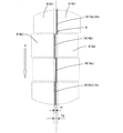
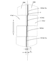
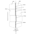
また、図4においては、方向Xの延長線上において、部分接合層16a,16b,16c,16dの4つは、紙面の下側に向かって左右方向に交互にずれた状態で配置されている。各部分接合層16a,16b,16c,16dの配置、別言すれば、それぞれのずれの方向については、図4に限定されることはない。接合層の配列状態の他の例として、図6〜図8のような配列状態を挙げることができる。ここで、図6〜図8は、接合層の配列状態の他の例を説明するための模式図である。
In addition, in FIG. 4, on the extension line in the direction X, the four
(実施例4〜12)
実施例4〜12においては、表1のセル構造の欄に示されるようなハニカムセグメントを複数個作製し、作製したハニカムセグメントを用いてハニカム構造体を作製した。各実施例において、表1の「セグメント数」の欄に示すような個数のハニカムセグメントを用いた。得られたハニカム構造体の「接合層の列の配置」、及び「隣り合うセグメントの最大ずれ量YMAX」、及び「最大ずれ比率」を表2に示す。
(Examples 4 to 12)
In Examples 4 to 12, a plurality of honeycomb segments as shown in the column of the cell structure in Table 1 were manufactured, and a honeycomb structure was manufactured using the manufactured honeycomb segments. In each example, the number of honeycomb segments as shown in the column of “number of segments” in Table 1 was used. Table 2 shows the “arrangement of the rows of the bonding layers”, the “maximum deviation amount Y MAX of adjacent segments”, and the “maximum deviation ratio” of the obtained honeycomb structure.
Priority Applications (4)
| Application Number | Priority Date | Filing Date | Title |
|---|---|---|---|
| JP2017008903A JP6802075B2 (en) | 2017-01-20 | 2017-01-20 | Honeycomb structure |
| US15/854,149 US10543446B2 (en) | 2017-01-20 | 2017-12-26 | Honeycomb structure |
| CN201810003800.7A CN108331642B (en) | 2017-01-20 | 2018-01-03 | Honeycomb structure |
| DE102018200762.4A DE102018200762B4 (en) | 2017-01-20 | 2018-01-18 | hONEYCOMB STRUCTURE |
Applications Claiming Priority (1)
| Application Number | Priority Date | Filing Date | Title |
|---|---|---|---|
| JP2017008903A JP6802075B2 (en) | 2017-01-20 | 2017-01-20 | Honeycomb structure |
Publications (3)
| Publication Number | Publication Date |
|---|---|
| JP2018114485A JP2018114485A (en) | 2018-07-26 |
| JP2018114485A5 true JP2018114485A5 (en) | 2020-02-06 |
| JP6802075B2 JP6802075B2 (en) | 2020-12-16 |
Family
ID=62813091
Family Applications (1)
| Application Number | Title | Priority Date | Filing Date |
|---|---|---|---|
| JP2017008903A Active JP6802075B2 (en) | 2017-01-20 | 2017-01-20 | Honeycomb structure |
Country Status (4)
| Country | Link |
|---|---|
| US (1) | US10543446B2 (en) |
| JP (1) | JP6802075B2 (en) |
| CN (1) | CN108331642B (en) |
| DE (1) | DE102018200762B4 (en) |
Families Citing this family (4)
| Publication number | Priority date | Publication date | Assignee | Title |
|---|---|---|---|---|
| JP7037985B2 (en) * | 2018-03-30 | 2022-03-17 | 日本碍子株式会社 | Honeycomb filter |
| CN112512659B (en) | 2018-08-23 | 2022-07-22 | 株式会社村田制作所 | Filtering and filtering device |
| WO2020045495A1 (en) * | 2018-08-30 | 2020-03-05 | 京セラ株式会社 | Ceramic structure |
| JP7160741B2 (en) * | 2019-03-28 | 2022-10-25 | 日本碍子株式会社 | honeycomb structure |
Family Cites Families (19)
| Publication number | Priority date | Publication date | Assignee | Title |
|---|---|---|---|---|
| JPS535781B2 (en) | 1973-12-25 | 1978-03-02 | ||
| DE60033977T2 (en) | 1999-09-29 | 2007-12-20 | Ibiden Co., Ltd., Ogaki | Honeycomb filter and arrangement of ceramic filters |
| JP4282960B2 (en) * | 2001-08-30 | 2009-06-24 | 日本碍子株式会社 | High-strength honeycomb structure, method of forming the same, and honeycomb structure converter |
| EP1618941B1 (en) | 2003-03-19 | 2013-02-27 | NGK Insulators, Ltd. | Honeycomb structure body |
| JP2005230680A (en) * | 2004-02-19 | 2005-09-02 | Ngk Insulators Ltd | Honeycomb structure |
| PL1728544T3 (en) * | 2004-03-23 | 2014-05-30 | Ngk Insulators Ltd | Honeycomb structure and method for manufacturing the same |
| DE102005019464A1 (en) * | 2005-04-27 | 2006-11-02 | Robert Bosch Gmbh | Soot filter for diesel engine exhaust system, has filter walls with catalytically-coated wavy surfaces made by extrusion to specified dimensions and geometric profile |
| CN100540111C (en) * | 2005-08-26 | 2009-09-16 | 揖斐电株式会社 | Honeycomb structured body and manufacture method thereof |
| US7491373B2 (en) * | 2006-11-15 | 2009-02-17 | Corning Incorporated | Flow-through honeycomb substrate and exhaust after treatment system and method |
| DE502008001738D1 (en) * | 2007-02-15 | 2010-12-23 | Mann & Hummel Gmbh | Diesel particulate filter with a ceramic filter body |
| JP2009256187A (en) * | 2008-03-24 | 2009-11-05 | Ibiden Co Ltd | Honeycomb structure, and method for producing honeycomb structure |
| JP2009233587A (en) * | 2008-03-27 | 2009-10-15 | Ngk Insulators Ltd | Diesel particulate filter with catalyst and its manufacturing method |
| WO2009141896A1 (en) * | 2008-05-20 | 2009-11-26 | イビデン株式会社 | Honeycomb structure and exhaust gas purification apparatus |
| JP5097237B2 (en) | 2010-03-31 | 2012-12-12 | 日本碍子株式会社 | Manufacturing method of honeycomb structure |
| JP5719645B2 (en) * | 2011-03-10 | 2015-05-20 | 株式会社エフ・シー・シー | Exhaust gas purification device |
| JP6059954B2 (en) * | 2012-10-30 | 2017-01-11 | 日本碍子株式会社 | Honeycomb filter |
| JP6014526B2 (en) * | 2013-03-22 | 2016-10-25 | 日本碍子株式会社 | Honeycomb structure |
| JP6320798B2 (en) * | 2014-03-04 | 2018-05-09 | 日本碍子株式会社 | Honeycomb structure |
| JP2017008903A (en) | 2015-06-26 | 2017-01-12 | カルソニックカンセイ株式会社 | Engine intake device |
-
2017
- 2017-01-20 JP JP2017008903A patent/JP6802075B2/en active Active
- 2017-12-26 US US15/854,149 patent/US10543446B2/en active Active
-
2018
- 2018-01-03 CN CN201810003800.7A patent/CN108331642B/en active Active
- 2018-01-18 DE DE102018200762.4A patent/DE102018200762B4/en active Active
Similar Documents
| Publication | Publication Date | Title |
|---|---|---|
| JP2018114485A5 (en) | ||
| JP2009051002A5 (en) | ||
| JP2008511768A5 (en) | ||
| JP2014034145A5 (en) | ||
| WO2015172050A3 (en) | Stacked two-dimensional materials and methods for producing structures incorporating same | |
| EP2228212A3 (en) | Multiply thin paper sheet having press-to-bond structure | |
| JP2020017955A5 (en) | ||
| JP2015088521A5 (en) | ||
| JP2015528128A5 (en) | ||
| RU2016138852A (en) | STRUCTURE OF THE AIRCRAFT TO ENSURE HIGH RESISTANCE TO THE DELAY OF THE COMPOSITE STRINGER | |
| JP2017534519A5 (en) | ||
| WO2009066620A1 (en) | Thermoelectric module | |
| JP2012063156A5 (en) | ||
| JP2012513614A5 (en) | ||
| JP2015109432A5 (en) | ||
| JP2013520024A5 (en) | Substrate support structure and combination of substrate support structure and substrate clamped on the surface of the substrate support structure | |
| JP2018153783A5 (en) | ||
| JP2009151311A5 (en) | ||
| JP2017536705A5 (en) | ||
| JP2013171981A5 (en) | ||
| JP2020526168A5 (en) | ||
| JP2015194255A5 (en) | ||
| WO2016113131A3 (en) | Solar module arrangement and method of assembling a solar module arrangement | |
| JP2019012684A5 (en) | ||
| JP6561225B2 (en) | Flooring |