JP2018105618A - Storage - Google Patents
Storage Download PDFInfo
- Publication number
- JP2018105618A JP2018105618A JP2018075342A JP2018075342A JP2018105618A JP 2018105618 A JP2018105618 A JP 2018105618A JP 2018075342 A JP2018075342 A JP 2018075342A JP 2018075342 A JP2018075342 A JP 2018075342A JP 2018105618 A JP2018105618 A JP 2018105618A
- Authority
- JP
- Japan
- Prior art keywords
- door
- storage
- refrigerator
- throat
- opening
- Prior art date
- Legal status (The legal status is an assumption and is not a legal conclusion. Google has not performed a legal analysis and makes no representation as to the accuracy of the status listed.)
- Pending
Links
Images


Abstract
Description
本発明の実施形態は貯蔵庫に関する。 Embodiments of the invention relate to storage.
従来より、冷蔵庫や冷凍庫あるいは温蔵庫等の貯蔵庫においては、庫内の貯蔵室を照明する庫内灯が設けられている。この庫内灯は、貯蔵室の側面や奥面など室壁面に設けられており、その室壁面から貯蔵室を照明するようになっている。 Conventionally, in a storage such as a refrigerator, a freezer, or a warm storage, an interior lamp for illuminating a storage room in the storage is provided. This interior lamp is provided on the wall surface of the storage room such as the side surface and the back surface, and the storage room is illuminated from the wall surface.
しかしながら、そのように貯蔵室の室壁面から貯蔵室を照明するものでは、庫内灯の近辺に貯蔵品が置かれることがあり、その場合、照明が貯蔵品で遮られ、貯蔵室に対する照度の低下が大きくなる。又、貯蔵室の奥面に庫内灯が設けられたものでは、扉を開けて貯蔵室を覗く使用者の目に照射光が直接入り、まぶしく感じられる。 However, in such a case where the storage room is illuminated from the wall surface of the storage room, the stored item may be placed near the interior light. In this case, the illumination is blocked by the stored item, and the illuminance of the storage room is reduced. Decrease increases. In addition, in the case where the interior lamp is provided on the inner surface of the storage room, the irradiation light directly enters the eyes of the user who opens the door and looks into the storage room, and it feels dazzling.
それに対して、貯蔵室に面する扉の背面部に存在するスロート部に庫内灯を設けたものが存在する(例えば特許文献1参照)。 On the other hand, there exists what provided the interior lamp in the throat part which exists in the back surface part of the door which faces a storage room (for example, refer patent document 1).
上述の、扉のスロート部に庫内灯を設けたものでは、扉をあけたときの庫内灯の近辺に貯蔵品が置かれることがなく、従って、照明が貯蔵品で遮られることがなく、貯蔵室に対する照度の低下が大きくなることはない。又、扉を開けて貯蔵室を覗く使用者の目に照射光が直接目に入るということもなく、まぶしく感じられることが少ない。 In the case where the interior lamp is provided at the throat portion of the door as described above, the stored item is not placed near the interior lamp when the door is opened, and therefore the lighting is not blocked by the stored item. The illuminance drop for the storage room does not increase. In addition, the irradiation light does not directly enter the eyes of the user who opens the door and looks into the storage room, and is rarely felt dazzling.
しかしながら、扉の開放時、庫内灯の照射光が貯蔵室に存在する棚の光沢のある前縁飾りを照らして反射され、それが使用者の目に入ってまぶしく感じられる。これは、扉のスロート部に庫内灯を設けて、扉の開放時に前側から貯蔵室を照明するようにしたものであるからこそ生じる問題点であり、貯蔵室の室壁面に庫内灯を設けて側方側や奥方側から貯蔵室を照明するものでは生じない問題点である。 However, when the door is opened, the light from the interior light is reflected by the shiny front edge decoration of the shelf existing in the storage room, which is dazzled by the user's eyes. This is a problem that arises because an interior lamp is provided at the throat of the door and the storage room is illuminated from the front side when the door is opened. This is a problem that does not occur when the storage room is illuminated from the side or back side.
そこで、扉のスロート部に照明装置を設けたもので、照射光が貯蔵室の棚の前縁飾りで反射されても、それが使用者の目に入ってまぶしく感じられることのない貯蔵庫を提供する。 Therefore, a lighting device is provided at the throat part of the door to provide a storage where the irradiated light is not reflected in the eyes of the user even if it is reflected by the front edge decoration of the shelf in the storage room. To do.
本実施形態の貯蔵庫は、内部に貯蔵室を有し、その貯蔵室に通じる開口部を前面に有する庫本体と、この庫本体の前記開口部を開閉するように設けられ、前記貯蔵室に面する背面部にスロート部を有する扉と、この扉の前記スロート部に設けられて、その扉の開放時に前記貯蔵室を照明する照明装置とを具備し、前記照明装置の前記貯蔵室に対する照射角度を上下方向に傾かせたことを特徴とする。 The storage of the present embodiment has a storage chamber inside, a storage body having an opening in front of the storage chamber, and a front opening for opening and closing the opening of the storage body. A door having a throat portion on the back surface, and a lighting device that is provided in the throat portion of the door and illuminates the storage chamber when the door is opened, and an irradiation angle of the lighting device with respect to the storage chamber It is characterized by tilting up and down.
以下、冷蔵庫に適用した一実施形態につき、図面を参照して説明する。
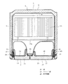
まず、図1には、冷蔵庫全体のうちの上半部を示しており、1が庫本体、2が扉を示している。このうち、庫本体1は、外箱3に内箱4を組合わせ、この外箱3と内箱4との間に断熱材5を充填して成るもので、内箱4の内部の最上部が冷蔵室6となっており、その下方が野菜室7となっている。これらの冷蔵室6及び野菜室7は貯蔵室であり、それぞれ前面は各貯蔵室に通じる開口部8,9となっている。
Hereinafter, an embodiment applied to a refrigerator will be described with reference to the drawings.
First, in FIG. 1, the upper half part of the whole refrigerator is shown, 1 shows the store | warehouse | chamber main body and 2 shows the door. Of these, the main body 1 is formed by combining the
冷蔵室6の内部には、棚10を複数段に設けており、そのいずれの棚10も前縁部に光沢のある飾り(前縁飾り)10aを有しており、最下部には貯蔵容器11が引出し可能に位置する貯蔵容器室12を有している。
Inside the refrigerator compartment 6,
それに対して、野菜室7は、図示しない野菜容器を引出し可能に有するものであり、その後方の奥部に、図示しないが、各貯蔵室を冷却するための、冷却器や庫内空気循環ファンが位置する冷却器室を有している。
On the other hand, the
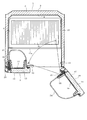
一方、扉2は、冷蔵室6の前面の開口部8を開閉するものであり、図2に示すように、外板13に内板14を組合わせ、この外板13と内板14との間に発泡断熱材15を充填して成るもので、左側に存在する。そして、右側にも今一枚の扉16があって、この扉16も、冷蔵室6の前面の開口部8を開閉するものであり、外板17に内板18を組合わせ、この外板17と内板18との間に発泡断熱材19を充填して成るものである。
On the other hand, the
すなわち、冷蔵室6の前面の開口部8は、扉2と扉16の2枚の扉で開閉するようにしており、詳しくは図示しないが、扉2は左端部を庫本体1に軸支し、扉16は右端部を庫本体1に軸支して、それぞれその各軸支部分を中心に回動する開き戸式で且つ観音開き式に開閉可能に設けている。なお、左側の扉2には、左右間の仕切部材20を、扉2の開放に支障を来たさない可動構造で取付けている。
That is, the opening 8 on the front surface of the refrigerator compartment 6 is opened and closed by two doors, the
扉2,16は、それぞれ冷蔵室6に面する背面部である内板14,18の背面にスロート部21,22を有している。これらのスロート部21,22は、図3に扉2のスロート部21で代表して示すように、内板14,18の各背面の周囲部から矩形の枠状に突出するもので、中空である。又、これらのスロート部21,22の各囲繞空間には、ポケット部23,24を複数段に設けている(ポケット部24は図2に示す)。そして、これらのスロート部21,22の各軸支部分側で上下方向に延びる一辺部の上下の中間部には、それぞれ照明装置25,26を設けている。
The
図4は、上記照明装置25,26の詳細を、扉2の照明装置25で代表して示しており、スロート部21,22の内部には基板ホルダ27を組込んでいる。この基板ホルダ27は、全体にスロート部21,22の内面に添う形状のもので、前側(図4では下側)が開口し先細で後側(同上側)が閉塞された容器状を成しており、スロート部21,22の内面に固着して固定している。又、この基板ホルダ27は、全体に例えば灰色で遮光性を有するものであり、スロート部21,22の外側(ポケット部23,24側とは反対側)に面する外側面部に開口部28を形成しており、この開口部28に対応してスロート部21,22の外側部にもそれとほゞ同じ大きさで同じ形状の開口部29を形成している。更に、この基板ホルダ27の開口部28に面する内側面部の内側には、基板保持爪30を設けている。
FIG. 4 shows the details of the
これに対して、扉2,16の外板13,17の内部には、コネクタハウジング31を組込んでいる。このコネクタハウジング31は、基部31aが外板13,17の内面に添うもので、この基部31aをその外板13,17の内面に固着して固定している。又、コネクタハウジング31の基部31aより後方(図4では上方)には、直方体状のケース部31bを形成しており、更に、そのケース部31bの後壁部のほゞ中央にはリード線挿通孔31cを形成し、このリード線挿通孔31cにシール32を介してリード線33を密に挿通している。すなわち、ケース部31bのリード線挿通孔31cは、リード線33を挿通する状態でシール32により密閉している。
On the other hand, a
リード線33は、前記庫本体1から扉2の軸支部分中を通して給電をするもので、ケース部31b外(基板ホルダ27側)に位置した先端部に入力側のコネクタ34を有している。
The
扉16の照明装置26は、上記扉2の照明装置25とは左右対称の構造で設けている。
この構成で、外板13,17の内部に前記発泡断熱材15,19(例えば発泡ポリウレタン)を注入し、内板14,18を外板13,17に組合わせ結合する。又、このとき、前記基板ホルダ27の前側の開口縁部にはシール35を貼着しておき、このシール35を、コネクタハウジング31のケース部31bの後面(リード線挿通孔31cの周囲部分)に圧接させることにより、基板ホルダ27の内部を外板13,17の内部から密に封止している。これにより、外板13,17の内部に注入した発泡断熱材15,19は、基板ホルダ27の内部に侵入することなく、扉2では外板13と内板14との間、扉16では外板17と内板18との間に、それぞれ充填される。
The
With this configuration, the foam
この後、照明装置25,26の光源であるLED36を実装した回路基板37が有するリード線38の先端部に設けた出力側のコネクタ39を、前記入力側のコネクタ34に接続し、回路基板37を基板ホルダ27の開口部28から基板保持爪30に係合させて装着する。そして、基板ホルダ27の開口部28には、シェード40を装着して開口部28,29を閉塞する。
Thereafter, an output-
なお、スロート部21,22の余剰空間には、発泡スチロール等の断熱材41を装填している。
図1は、以上のようにして照明装置25を組込んだ扉2を開放状態で表しており、この図1に矢印Lで示すように、照明装置25のLED36からシェード40を透して前記冷蔵室6に照射される光の照射角度は、上下方向に傾かせており、中でも下向きに傾かせている(扉16側も、図示しないが同様である)。
In addition, the surplus space of the
FIG. 1 shows the
この照射角度Lについては、回路基板37を同方向に傾かせて設置することにより実現するようにしており、そのほか、回路基板37は傾かせずにシェード40に光の屈折を同方向にするものを使用したり、LED36に脚(リード)の長い砲弾形状のものを使用して、その脚の例えば一方を曲げることにより、LED36を同方向に傾けて実装したり、回路基板37に小さく複数に分けたものを使用して、それらを同方向に傾かせて設置したりすることでも実現できる。
The irradiation angle L is realized by installing the
又、図2には、照明装置25,26に対応して庫本体1の断熱壁中に設けた扉開閉検知手段であるスイッチ42,43を示しており、これらは例えばタクトスイッチやマイクロスイッチであって、詳しくは図示しないが、ともに庫本体1の内部に突出した突子が扉2,16の閉鎖によりスロート部21,22(各軸支部分側の一辺部)で押圧されることによって、扉2,16の閉鎖を検知し、その突子の押圧が扉2,16の閉鎖により解除されることにより、扉2,16の開放を検知するようになっている。照明装置25,26は、このスイッチ42,43が扉2,16の開放を検知したときにLED36を発光させ、扉2,16の閉鎖を検知したときにLED36を消光させるようになっている。
Further, FIG. 2 shows switches 42 and 43 which are door opening / closing detection means provided in the heat insulating wall of the main body 1 corresponding to the
次に、上記構成の冷蔵庫の作用を述べる。
上記構成の冷蔵庫においては、扉2,16を開放すると、スイッチ42,43が扉2,16の開放を検知することにより、照明装置25,26のLED36を発光させ、図5に照射域S1,S2で示すように、冷蔵室6を照明する。
Next, the operation of the refrigerator having the above configuration will be described.
In the refrigerator having the above-described configuration, when the
又、この場合、扉2,16の一方のみを開放すると、スイッチ42,43のうちの開放された扉側のスイッチが扉の開放を検知することにより、照明装置25,26のうちの開放された扉側の照明装置のLED36を発光させ、図6に扉16が開放された場合で代表して示すように、冷蔵室6を照明する。すなわち、この場合には、扉2,16のうちの開放された扉側の照明装置のLED36を発光させることのみを行い、開放されない扉側の照明装置のLED36を発光させることは行わない。これにより、消費電力の節減を図っている。
Further, in this case, when only one of the
そして、上記構成の冷蔵庫においては、照明装置25,26を扉2,16のスロート部21,22に設けており、冷蔵室6の室壁面に庫内灯を設けたもののような、扉2,16をあけたときの照明装置の近辺に貯蔵品が置かれることがないので、照明が貯蔵品で遮られることがなく、従って、冷蔵室6に対する照度の低下が大きくなることがなく、且つ、扉2,16を開けて冷蔵室6を覗く使用者の目に照射光が直接目に入るということもなくて、使用者にまぶしく感じられることが少ない。
And in the refrigerator of the said structure, the illuminating
併せて、上記構成の冷蔵庫においては、照明装置25,26の冷蔵室6に対する照射角度を上下方向に傾かせており、これによって、照射光が冷蔵室6の棚10の前縁飾り10aで反射されても、それが使用者の目に入ってまぶしく感じられることもないようにできる。すなわち、既述の、扉2,16のスロート部21,22に照明装置25,26を設けて、扉2,16の開放時に前側から冷蔵室6を照明するようにしたものであるからこその問題点を解決できるのである。
In addition, in the refrigerator having the above-described configuration, the irradiation angle of the
更に、上記構成の冷蔵庫においては、照明装置25,26の冷蔵室6に対する照射角度を上下方向のうちでも下向きに傾かせており、これによって、棚10の上に置いた貯蔵品を、下側から照明するよりも、上側から効果的に照明し、それの判別がより明確にできる。
Furthermore, in the refrigerator of the said structure, the irradiation angle with respect to the refrigerator compartment 6 of the illuminating
そのほか、LED36を実装した回路基板37を装着した基板ホルダ27は、全体に遮光性を有しており、これによって、LED36の発光時に、その光によってスロート部21,22内の基板ホルダ27やコネクタ39,34等のパーツがスロート部21,22の特にポケット部23,24側の側壁を透かせて見えるのを防ぐことができ、商品性を高めることができる。なお、基板ホルダ27の遮光性は、基板ホルダ27の全体ではなく、ポケット部23,24側にのみ有するものであっても良い。
In addition, the
加えて、上記構成の冷蔵庫においては、照明装置25,26の光源としてLED36を使用しており、LED36は輝度が高くて嵩的にも薄形化が可能なものであり、薄いスロート部21,22に難なく組込むことができる。ちなみに、従来の庫内灯(蛍光灯)であると、これを薄いスロート部21,22に組込むには、庫内灯を小さくせざるを得ず、この小さい庫内灯では輝度が低くて充分な照明効果を得ることができない。その点、照明装置25,26の光源としてLED36を使用した上記構成の冷蔵庫においては、それを薄いスロート部21,22に組込むことが難なくできる上に輝度も高いので、充分な照明効果を得ることができる。
In addition, in the refrigerator having the above-described configuration, the
更に、LED36の輝度の高さのため、冷蔵室6の棚10の前縁飾り10aによる反射光も強くなるが、それを上記構成の冷蔵庫においては、照明装置25,26の冷蔵室6に対する照射角度を上下方向に傾かせたことにより、使用者の目に反射光が入ってまぶしく感じられることのないようにできるものでもある。
Furthermore, because of the high brightness of the
なお、上記構成の冷蔵庫(貯蔵庫)における照明装置25,26は、庫内を撮影するカメラを有するものでは、カメラ作動時に照明装置25,26を連動させることにより、照明による照明が庫内撮影時の補助となるようにすると良い。
In addition, the
以上説明した貯蔵庫は、上記実施形態にのみ限定されるものではなく、特に冷蔵庫以外の例えば冷凍庫や温蔵庫等の貯蔵庫への適用が可能であるなど、要旨を逸脱しない範囲内で適宜変更して実施し得る。 The storage described above is not limited to the above embodiment, and can be appropriately changed within a range not departing from the gist, such as being applicable to a storage other than a refrigerator, for example, a freezer or a warm storage. Can be implemented.
そのほか、本発明の実施形態を説明したが、この実施形態は、例として提示したものであり、発明の範囲を限定することは意図していない。この新規な実施形態は、その他の様々な形態で実施されることが可能であり、発明の要旨を逸脱しない範囲で、種々の省略、置き換え、変更を行うことができる。この実施形態やその変形は、発明の範囲や要旨に含まれると共に、特許請求の範囲に記載された発明とその均等の範囲に含まれる。 In addition, although the embodiment of the present invention has been described, this embodiment is presented as an example and is not intended to limit the scope of the invention. The novel embodiment can be implemented in various other forms, and various omissions, replacements, and changes can be made without departing from the scope of the invention. This embodiment and its modifications are included in the scope and gist of the invention, and are included in the invention described in the claims and the equivalents thereof.
図面中、1は庫本体、2は扉、6は冷蔵室(貯蔵室)、8は開口部、16は扉、21,22はスロート部、25,26は照明装置、Lは照明装置の照射角度を示す。 In the drawings, 1 is a storage body, 2 is a door, 6 is a refrigerator compartment (storage room), 8 is an opening, 16 is a door, 21 and 22 are throat portions, 25 and 26 are illumination devices, and L is an illumination device. Indicates the angle.
Claims (1)
この庫本体の前記開口部を開閉するように設けられ、前記貯蔵室に面する背面部にスロート部を有する扉と、
この扉の前記スロート部に設けられて、その扉の開放時に前記貯蔵室を照明する照明装置とを具備し、
前記照明装置の前記貯蔵室に対する照射角度を上下方向に傾かせたことを特徴とする貯蔵庫。 A storage body having a storage chamber inside and having an opening on the front surface leading to the storage chamber;
A door provided to open and close the opening of the main body, and having a throat portion on a back surface facing the storage chamber;
Provided in the throat portion of this door, comprising a lighting device that illuminates the storage room when the door is opened,
The storehouse characterized by making the irradiation angle with respect to the said storage room of the said illuminating device tilted up and down.
Priority Applications (1)
| Application Number | Priority Date | Filing Date | Title |
|---|---|---|---|
| JP2018075342A JP2018105618A (en) | 2018-04-10 | 2018-04-10 | Storage |
Applications Claiming Priority (1)
| Application Number | Priority Date | Filing Date | Title |
|---|---|---|---|
| JP2018075342A JP2018105618A (en) | 2018-04-10 | 2018-04-10 | Storage |
Related Parent Applications (1)
| Application Number | Title | Priority Date | Filing Date |
|---|---|---|---|
| JP2013120791A Division JP6325203B2 (en) | 2013-06-07 | 2013-06-07 | Storage |
Related Child Applications (1)
| Application Number | Title | Priority Date | Filing Date |
|---|---|---|---|
| JP2019209561A Division JP7096229B2 (en) | 2019-11-20 | 2019-11-20 | Storage |
Publications (2)
| Publication Number | Publication Date |
|---|---|
| JP2018105618A true JP2018105618A (en) | 2018-07-05 |
| JP2018105618A5 JP2018105618A5 (en) | 2019-05-09 |
Family
ID=62787005
Family Applications (1)
| Application Number | Title | Priority Date | Filing Date |
|---|---|---|---|
| JP2018075342A Pending JP2018105618A (en) | 2018-04-10 | 2018-04-10 | Storage |
Country Status (1)
| Country | Link |
|---|---|
| JP (1) | JP2018105618A (en) |
-
2018
- 2018-04-10 JP JP2018075342A patent/JP2018105618A/en active Pending
Similar Documents
| Publication | Publication Date | Title |
|---|---|---|
| JP6325203B2 (en) | Storage | |
| US7905614B2 (en) | Refrigerator | |
| JP2008070080A (en) | Refrigerator | |
| KR20180013186A (en) | Refrigerator | |
| JP2011196674A (en) | Refrigerator | |
| JP2015158333A (en) | refrigerator | |
| US6478445B1 (en) | Lighting assembly for a refrigeration appliance | |
| JP2012037074A (en) | Refrigerator | |
| JP2008089279A (en) | Refrigerator | |
| US11454388B2 (en) | Refrigerator | |
| JP2008089277A (en) | Refrigerator | |
| JP2018105618A (en) | Storage | |
| JP7096229B2 (en) | Storage | |
| JP6282489B2 (en) | Storage | |
| CN110017656B (en) | Domestic refrigeration device with lighting device | |
| JP2017194181A (en) | Storage | |
| JP7145142B2 (en) | storage | |
| JP2008106976A (en) | Refrigerator | |
| KR101553947B1 (en) | Refrigerator | |
| JP6836521B2 (en) | Storage | |
| JP2013079805A (en) | Showcase | |
| KR20180035203A (en) | Refrigerator | |
| CN111102795B (en) | Household appliance with projection device and method for operating household appliance | |
| CN209893798U (en) | Lighting assembly of refrigerator and refrigerator | |
| JP5253920B2 (en) | Showcase |
Legal Events
| Date | Code | Title | Description |
|---|---|---|---|
| A621 | Written request for application examination |
Free format text: JAPANESE INTERMEDIATE CODE: A621 Effective date: 20180510 |
|
| A521 | Written amendment |
Free format text: JAPANESE INTERMEDIATE CODE: A523 Effective date: 20190318 |
|
| A977 | Report on retrieval |
Free format text: JAPANESE INTERMEDIATE CODE: A971007 Effective date: 20190328 |
|
| A131 | Notification of reasons for refusal |
Free format text: JAPANESE INTERMEDIATE CODE: A131 Effective date: 20190402 |
|
| A02 | Decision of refusal |
Free format text: JAPANESE INTERMEDIATE CODE: A02 Effective date: 20190820 |