JP2018105196A - Exhaust emission control device for internal combustion engine - Google Patents

Exhaust emission control device for internal combustion engine Download PDF

Info

Publication number
JP2018105196A
JP2018105196A JP2016251243A JP2016251243A JP2018105196A JP 2018105196 A JP2018105196 A JP 2018105196A JP 2016251243 A JP2016251243 A JP 2016251243A JP 2016251243 A JP2016251243 A JP 2016251243A JP 2018105196 A JP2018105196 A JP 2018105196A
Authority
JP
Japan
Prior art keywords
temperature
heat
catalyst
exhaust treatment
treatment catalyst
Prior art date
Legal status (The legal status is an assumption and is not a legal conclusion. Google has not performed a legal analysis and makes no representation as to the accuracy of the status listed.)
Granted
Application number
JP2016251243A
Other languages
Japanese (ja)
Other versions
JP6551385B2 (en
Inventor
藤原 清
Kiyoshi Fujiwara
清 藤原
竹島 伸一
Shinichi Takeshima
伸一 竹島
寛真 西岡
Hiromasa Nishioka
寛真 西岡
Current Assignee (The listed assignees may be inaccurate. Google has not performed a legal analysis and makes no representation or warranty as to the accuracy of the list.)
Toyota Motor Corp
Original Assignee
Toyota Motor Corp
Priority date (The priority date is an assumption and is not a legal conclusion. Google has not performed a legal analysis and makes no representation as to the accuracy of the date listed.)
Filing date
Publication date
Application filed by Toyota Motor Corp filed Critical Toyota Motor Corp
Priority to JP2016251243A priority Critical patent/JP6551385B2/en
Priority to US15/798,781 priority patent/US10280856B2/en
Priority to EP17203630.3A priority patent/EP3339586B1/en
Priority to CN201711421606.2A priority patent/CN108240252B/en
Publication of JP2018105196A publication Critical patent/JP2018105196A/en
Application granted granted Critical
Publication of JP6551385B2 publication Critical patent/JP6551385B2/en
Expired - Fee Related legal-status Critical Current
Anticipated expiration legal-status Critical

Links

Images

Classifications

    • FMECHANICAL ENGINEERING; LIGHTING; HEATING; WEAPONS; BLASTING
    • F01MACHINES OR ENGINES IN GENERAL; ENGINE PLANTS IN GENERAL; STEAM ENGINES
    • F01NGAS-FLOW SILENCERS OR EXHAUST APPARATUS FOR MACHINES OR ENGINES IN GENERAL; GAS-FLOW SILENCERS OR EXHAUST APPARATUS FOR INTERNAL COMBUSTION ENGINES
    • F01N3/00Exhaust or silencing apparatus having means for purifying, rendering innocuous, or otherwise treating exhaust
    • F01N3/08Exhaust or silencing apparatus having means for purifying, rendering innocuous, or otherwise treating exhaust for rendering innocuous
    • F01N3/10Exhaust or silencing apparatus having means for purifying, rendering innocuous, or otherwise treating exhaust for rendering innocuous by thermal or catalytic conversion of noxious components of exhaust
    • F01N3/18Exhaust or silencing apparatus having means for purifying, rendering innocuous, or otherwise treating exhaust for rendering innocuous by thermal or catalytic conversion of noxious components of exhaust characterised by methods of operation; Control
    • F01N3/20Exhaust or silencing apparatus having means for purifying, rendering innocuous, or otherwise treating exhaust for rendering innocuous by thermal or catalytic conversion of noxious components of exhaust characterised by methods of operation; Control specially adapted for catalytic conversion ; Methods of operation or control of catalytic converters
    • F01N3/2006Periodically heating or cooling catalytic reactors, e.g. at cold starting or overheating
    • FMECHANICAL ENGINEERING; LIGHTING; HEATING; WEAPONS; BLASTING
    • F02COMBUSTION ENGINES; HOT-GAS OR COMBUSTION-PRODUCT ENGINE PLANTS
    • F02DCONTROLLING COMBUSTION ENGINES
    • F02D41/00Electrical control of supply of combustible mixture or its constituents
    • F02D41/02Circuit arrangements for generating control signals
    • F02D41/021Introducing corrections for particular conditions exterior to the engine
    • F02D41/0235Introducing corrections for particular conditions exterior to the engine in relation with the state of the exhaust gas treating apparatus
    • F02D41/024Introducing corrections for particular conditions exterior to the engine in relation with the state of the exhaust gas treating apparatus to increase temperature of the exhaust gas treating apparatus
    • F02D41/0255Introducing corrections for particular conditions exterior to the engine in relation with the state of the exhaust gas treating apparatus to increase temperature of the exhaust gas treating apparatus to accelerate the warming-up of the exhaust gas treating apparatus at engine start
    • FMECHANICAL ENGINEERING; LIGHTING; HEATING; WEAPONS; BLASTING
    • F01MACHINES OR ENGINES IN GENERAL; ENGINE PLANTS IN GENERAL; STEAM ENGINES
    • F01NGAS-FLOW SILENCERS OR EXHAUST APPARATUS FOR MACHINES OR ENGINES IN GENERAL; GAS-FLOW SILENCERS OR EXHAUST APPARATUS FOR INTERNAL COMBUSTION ENGINES
    • F01N11/00Monitoring or diagnostic devices for exhaust-gas treatment apparatus, e.g. for catalytic activity
    • F01N11/002Monitoring or diagnostic devices for exhaust-gas treatment apparatus, e.g. for catalytic activity the diagnostic devices measuring or estimating temperature or pressure in, or downstream of the exhaust apparatus
    • F01N11/005Monitoring or diagnostic devices for exhaust-gas treatment apparatus, e.g. for catalytic activity the diagnostic devices measuring or estimating temperature or pressure in, or downstream of the exhaust apparatus the temperature or pressure being estimated, e.g. by means of a theoretical model
    • FMECHANICAL ENGINEERING; LIGHTING; HEATING; WEAPONS; BLASTING
    • F01MACHINES OR ENGINES IN GENERAL; ENGINE PLANTS IN GENERAL; STEAM ENGINES
    • F01NGAS-FLOW SILENCERS OR EXHAUST APPARATUS FOR MACHINES OR ENGINES IN GENERAL; GAS-FLOW SILENCERS OR EXHAUST APPARATUS FOR INTERNAL COMBUSTION ENGINES
    • F01N3/00Exhaust or silencing apparatus having means for purifying, rendering innocuous, or otherwise treating exhaust
    • F01N3/08Exhaust or silencing apparatus having means for purifying, rendering innocuous, or otherwise treating exhaust for rendering innocuous
    • F01N3/0807Exhaust or silencing apparatus having means for purifying, rendering innocuous, or otherwise treating exhaust for rendering innocuous by using absorbents or adsorbents
    • F01N3/0814Exhaust or silencing apparatus having means for purifying, rendering innocuous, or otherwise treating exhaust for rendering innocuous by using absorbents or adsorbents combined with catalytic converters, e.g. NOx absorption/storage reduction catalysts
    • FMECHANICAL ENGINEERING; LIGHTING; HEATING; WEAPONS; BLASTING
    • F01MACHINES OR ENGINES IN GENERAL; ENGINE PLANTS IN GENERAL; STEAM ENGINES
    • F01NGAS-FLOW SILENCERS OR EXHAUST APPARATUS FOR MACHINES OR ENGINES IN GENERAL; GAS-FLOW SILENCERS OR EXHAUST APPARATUS FOR INTERNAL COMBUSTION ENGINES
    • F01N3/00Exhaust or silencing apparatus having means for purifying, rendering innocuous, or otherwise treating exhaust
    • F01N3/08Exhaust or silencing apparatus having means for purifying, rendering innocuous, or otherwise treating exhaust for rendering innocuous
    • F01N3/0807Exhaust or silencing apparatus having means for purifying, rendering innocuous, or otherwise treating exhaust for rendering innocuous by using absorbents or adsorbents
    • F01N3/0828Exhaust or silencing apparatus having means for purifying, rendering innocuous, or otherwise treating exhaust for rendering innocuous by using absorbents or adsorbents characterised by the absorbed or adsorbed substances
    • F01N3/0842Nitrogen oxides
    • FMECHANICAL ENGINEERING; LIGHTING; HEATING; WEAPONS; BLASTING
    • F01MACHINES OR ENGINES IN GENERAL; ENGINE PLANTS IN GENERAL; STEAM ENGINES
    • F01NGAS-FLOW SILENCERS OR EXHAUST APPARATUS FOR MACHINES OR ENGINES IN GENERAL; GAS-FLOW SILENCERS OR EXHAUST APPARATUS FOR INTERNAL COMBUSTION ENGINES
    • F01N3/00Exhaust or silencing apparatus having means for purifying, rendering innocuous, or otherwise treating exhaust
    • F01N3/08Exhaust or silencing apparatus having means for purifying, rendering innocuous, or otherwise treating exhaust for rendering innocuous
    • F01N3/0807Exhaust or silencing apparatus having means for purifying, rendering innocuous, or otherwise treating exhaust for rendering innocuous by using absorbents or adsorbents
    • F01N3/0871Regulation of absorbents or adsorbents, e.g. purging
    • F01N3/0885Regeneration of deteriorated absorbents or adsorbents, e.g. desulfurization of NOx traps
    • FMECHANICAL ENGINEERING; LIGHTING; HEATING; WEAPONS; BLASTING
    • F01MACHINES OR ENGINES IN GENERAL; ENGINE PLANTS IN GENERAL; STEAM ENGINES
    • F01NGAS-FLOW SILENCERS OR EXHAUST APPARATUS FOR MACHINES OR ENGINES IN GENERAL; GAS-FLOW SILENCERS OR EXHAUST APPARATUS FOR INTERNAL COMBUSTION ENGINES
    • F01N3/00Exhaust or silencing apparatus having means for purifying, rendering innocuous, or otherwise treating exhaust
    • F01N3/08Exhaust or silencing apparatus having means for purifying, rendering innocuous, or otherwise treating exhaust for rendering innocuous
    • F01N3/10Exhaust or silencing apparatus having means for purifying, rendering innocuous, or otherwise treating exhaust for rendering innocuous by thermal or catalytic conversion of noxious components of exhaust
    • F01N3/18Exhaust or silencing apparatus having means for purifying, rendering innocuous, or otherwise treating exhaust for rendering innocuous by thermal or catalytic conversion of noxious components of exhaust characterised by methods of operation; Control
    • F01N3/20Exhaust or silencing apparatus having means for purifying, rendering innocuous, or otherwise treating exhaust for rendering innocuous by thermal or catalytic conversion of noxious components of exhaust characterised by methods of operation; Control specially adapted for catalytic conversion ; Methods of operation or control of catalytic converters
    • F01N3/2006Periodically heating or cooling catalytic reactors, e.g. at cold starting or overheating
    • F01N3/2033Periodically heating or cooling catalytic reactors, e.g. at cold starting or overheating using a fuel burner or introducing fuel into exhaust duct
    • FMECHANICAL ENGINEERING; LIGHTING; HEATING; WEAPONS; BLASTING
    • F01MACHINES OR ENGINES IN GENERAL; ENGINE PLANTS IN GENERAL; STEAM ENGINES
    • F01NGAS-FLOW SILENCERS OR EXHAUST APPARATUS FOR MACHINES OR ENGINES IN GENERAL; GAS-FLOW SILENCERS OR EXHAUST APPARATUS FOR INTERNAL COMBUSTION ENGINES
    • F01N3/00Exhaust or silencing apparatus having means for purifying, rendering innocuous, or otherwise treating exhaust
    • F01N3/08Exhaust or silencing apparatus having means for purifying, rendering innocuous, or otherwise treating exhaust for rendering innocuous
    • F01N3/10Exhaust or silencing apparatus having means for purifying, rendering innocuous, or otherwise treating exhaust for rendering innocuous by thermal or catalytic conversion of noxious components of exhaust
    • F01N3/18Exhaust or silencing apparatus having means for purifying, rendering innocuous, or otherwise treating exhaust for rendering innocuous by thermal or catalytic conversion of noxious components of exhaust characterised by methods of operation; Control
    • F01N3/20Exhaust or silencing apparatus having means for purifying, rendering innocuous, or otherwise treating exhaust for rendering innocuous by thermal or catalytic conversion of noxious components of exhaust characterised by methods of operation; Control specially adapted for catalytic conversion ; Methods of operation or control of catalytic converters
    • F01N3/206Adding periodically or continuously substances to exhaust gases for promoting purification, e.g. catalytic material in liquid form, NOx reducing agents
    • FMECHANICAL ENGINEERING; LIGHTING; HEATING; WEAPONS; BLASTING
    • F01MACHINES OR ENGINES IN GENERAL; ENGINE PLANTS IN GENERAL; STEAM ENGINES
    • F01NGAS-FLOW SILENCERS OR EXHAUST APPARATUS FOR MACHINES OR ENGINES IN GENERAL; GAS-FLOW SILENCERS OR EXHAUST APPARATUS FOR INTERNAL COMBUSTION ENGINES
    • F01N3/00Exhaust or silencing apparatus having means for purifying, rendering innocuous, or otherwise treating exhaust
    • F01N3/08Exhaust or silencing apparatus having means for purifying, rendering innocuous, or otherwise treating exhaust for rendering innocuous
    • F01N3/10Exhaust or silencing apparatus having means for purifying, rendering innocuous, or otherwise treating exhaust for rendering innocuous by thermal or catalytic conversion of noxious components of exhaust
    • F01N3/24Exhaust or silencing apparatus having means for purifying, rendering innocuous, or otherwise treating exhaust for rendering innocuous by thermal or catalytic conversion of noxious components of exhaust characterised by constructional aspects of converting apparatus
    • F01N3/28Construction of catalytic reactors
    • FMECHANICAL ENGINEERING; LIGHTING; HEATING; WEAPONS; BLASTING
    • F01MACHINES OR ENGINES IN GENERAL; ENGINE PLANTS IN GENERAL; STEAM ENGINES
    • F01NGAS-FLOW SILENCERS OR EXHAUST APPARATUS FOR MACHINES OR ENGINES IN GENERAL; GAS-FLOW SILENCERS OR EXHAUST APPARATUS FOR INTERNAL COMBUSTION ENGINES
    • F01N3/00Exhaust or silencing apparatus having means for purifying, rendering innocuous, or otherwise treating exhaust
    • F01N3/08Exhaust or silencing apparatus having means for purifying, rendering innocuous, or otherwise treating exhaust for rendering innocuous
    • F01N3/10Exhaust or silencing apparatus having means for purifying, rendering innocuous, or otherwise treating exhaust for rendering innocuous by thermal or catalytic conversion of noxious components of exhaust
    • F01N3/24Exhaust or silencing apparatus having means for purifying, rendering innocuous, or otherwise treating exhaust for rendering innocuous by thermal or catalytic conversion of noxious components of exhaust characterised by constructional aspects of converting apparatus
    • F01N3/36Arrangements for supply of additional fuel
    • FMECHANICAL ENGINEERING; LIGHTING; HEATING; WEAPONS; BLASTING
    • F01MACHINES OR ENGINES IN GENERAL; ENGINE PLANTS IN GENERAL; STEAM ENGINES
    • F01NGAS-FLOW SILENCERS OR EXHAUST APPARATUS FOR MACHINES OR ENGINES IN GENERAL; GAS-FLOW SILENCERS OR EXHAUST APPARATUS FOR INTERNAL COMBUSTION ENGINES
    • F01N9/00Electrical control of exhaust gas treating apparatus
    • F01N9/005Electrical control of exhaust gas treating apparatus using models instead of sensors to determine operating characteristics of exhaust systems, e.g. calculating catalyst temperature instead of measuring it directly
    • FMECHANICAL ENGINEERING; LIGHTING; HEATING; WEAPONS; BLASTING
    • F02COMBUSTION ENGINES; HOT-GAS OR COMBUSTION-PRODUCT ENGINE PLANTS
    • F02DCONTROLLING COMBUSTION ENGINES
    • F02D41/00Electrical control of supply of combustible mixture or its constituents
    • F02D41/02Circuit arrangements for generating control signals
    • F02D41/021Introducing corrections for particular conditions exterior to the engine
    • F02D41/0235Introducing corrections for particular conditions exterior to the engine in relation with the state of the exhaust gas treating apparatus
    • F02D41/027Introducing corrections for particular conditions exterior to the engine in relation with the state of the exhaust gas treating apparatus to purge or regenerate the exhaust gas treating apparatus
    • FMECHANICAL ENGINEERING; LIGHTING; HEATING; WEAPONS; BLASTING
    • F01MACHINES OR ENGINES IN GENERAL; ENGINE PLANTS IN GENERAL; STEAM ENGINES
    • F01NGAS-FLOW SILENCERS OR EXHAUST APPARATUS FOR MACHINES OR ENGINES IN GENERAL; GAS-FLOW SILENCERS OR EXHAUST APPARATUS FOR INTERNAL COMBUSTION ENGINES
    • F01N2240/00Combination or association of two or more different exhaust treating devices, or of at least one such device with an auxiliary device, not covered by indexing codes F01N2230/00 or F01N2250/00, one of the devices being
    • F01N2240/02Combination or association of two or more different exhaust treating devices, or of at least one such device with an auxiliary device, not covered by indexing codes F01N2230/00 or F01N2250/00, one of the devices being a heat exchanger
    • FMECHANICAL ENGINEERING; LIGHTING; HEATING; WEAPONS; BLASTING
    • F01MACHINES OR ENGINES IN GENERAL; ENGINE PLANTS IN GENERAL; STEAM ENGINES
    • F01NGAS-FLOW SILENCERS OR EXHAUST APPARATUS FOR MACHINES OR ENGINES IN GENERAL; GAS-FLOW SILENCERS OR EXHAUST APPARATUS FOR INTERNAL COMBUSTION ENGINES
    • F01N2240/00Combination or association of two or more different exhaust treating devices, or of at least one such device with an auxiliary device, not covered by indexing codes F01N2230/00 or F01N2250/00, one of the devices being
    • F01N2240/30Combination or association of two or more different exhaust treating devices, or of at least one such device with an auxiliary device, not covered by indexing codes F01N2230/00 or F01N2250/00, one of the devices being a fuel reformer
    • FMECHANICAL ENGINEERING; LIGHTING; HEATING; WEAPONS; BLASTING
    • F01MACHINES OR ENGINES IN GENERAL; ENGINE PLANTS IN GENERAL; STEAM ENGINES
    • F01NGAS-FLOW SILENCERS OR EXHAUST APPARATUS FOR MACHINES OR ENGINES IN GENERAL; GAS-FLOW SILENCERS OR EXHAUST APPARATUS FOR INTERNAL COMBUSTION ENGINES
    • F01N2550/00Monitoring or diagnosing the deterioration of exhaust systems
    • F01N2550/02Catalytic activity of catalytic converters
    • FMECHANICAL ENGINEERING; LIGHTING; HEATING; WEAPONS; BLASTING
    • F01MACHINES OR ENGINES IN GENERAL; ENGINE PLANTS IN GENERAL; STEAM ENGINES
    • F01NGAS-FLOW SILENCERS OR EXHAUST APPARATUS FOR MACHINES OR ENGINES IN GENERAL; GAS-FLOW SILENCERS OR EXHAUST APPARATUS FOR INTERNAL COMBUSTION ENGINES
    • F01N2560/00Exhaust systems with means for detecting or measuring exhaust gas components or characteristics
    • F01N2560/06Exhaust systems with means for detecting or measuring exhaust gas components or characteristics the means being a temperature sensor
    • FMECHANICAL ENGINEERING; LIGHTING; HEATING; WEAPONS; BLASTING
    • F01MACHINES OR ENGINES IN GENERAL; ENGINE PLANTS IN GENERAL; STEAM ENGINES
    • F01NGAS-FLOW SILENCERS OR EXHAUST APPARATUS FOR MACHINES OR ENGINES IN GENERAL; GAS-FLOW SILENCERS OR EXHAUST APPARATUS FOR INTERNAL COMBUSTION ENGINES
    • F01N2610/00Adding substances to exhaust gases
    • F01N2610/02Adding substances to exhaust gases the substance being ammonia or urea
    • FMECHANICAL ENGINEERING; LIGHTING; HEATING; WEAPONS; BLASTING
    • F01MACHINES OR ENGINES IN GENERAL; ENGINE PLANTS IN GENERAL; STEAM ENGINES
    • F01NGAS-FLOW SILENCERS OR EXHAUST APPARATUS FOR MACHINES OR ENGINES IN GENERAL; GAS-FLOW SILENCERS OR EXHAUST APPARATUS FOR INTERNAL COMBUSTION ENGINES
    • F01N2610/00Adding substances to exhaust gases
    • F01N2610/04Adding substances to exhaust gases the substance being hydrogen
    • FMECHANICAL ENGINEERING; LIGHTING; HEATING; WEAPONS; BLASTING
    • F01MACHINES OR ENGINES IN GENERAL; ENGINE PLANTS IN GENERAL; STEAM ENGINES
    • F01NGAS-FLOW SILENCERS OR EXHAUST APPARATUS FOR MACHINES OR ENGINES IN GENERAL; GAS-FLOW SILENCERS OR EXHAUST APPARATUS FOR INTERNAL COMBUSTION ENGINES
    • F01N2900/00Details of electrical control or of the monitoring of the exhaust gas treating apparatus
    • F01N2900/06Parameters used for exhaust control or diagnosing
    • F01N2900/14Parameters used for exhaust control or diagnosing said parameters being related to the exhaust gas
    • F01N2900/1411Exhaust gas flow rate, e.g. mass flow rate or volumetric flow rate
    • FMECHANICAL ENGINEERING; LIGHTING; HEATING; WEAPONS; BLASTING
    • F01MACHINES OR ENGINES IN GENERAL; ENGINE PLANTS IN GENERAL; STEAM ENGINES
    • F01NGAS-FLOW SILENCERS OR EXHAUST APPARATUS FOR MACHINES OR ENGINES IN GENERAL; GAS-FLOW SILENCERS OR EXHAUST APPARATUS FOR INTERNAL COMBUSTION ENGINES
    • F01N2900/00Details of electrical control or of the monitoring of the exhaust gas treating apparatus
    • F01N2900/06Parameters used for exhaust control or diagnosing
    • F01N2900/16Parameters used for exhaust control or diagnosing said parameters being related to the exhaust apparatus, e.g. particulate filter or catalyst
    • F01N2900/1602Temperature of exhaust gas apparatus
    • FMECHANICAL ENGINEERING; LIGHTING; HEATING; WEAPONS; BLASTING
    • F01MACHINES OR ENGINES IN GENERAL; ENGINE PLANTS IN GENERAL; STEAM ENGINES
    • F01NGAS-FLOW SILENCERS OR EXHAUST APPARATUS FOR MACHINES OR ENGINES IN GENERAL; GAS-FLOW SILENCERS OR EXHAUST APPARATUS FOR INTERNAL COMBUSTION ENGINES
    • F01N2900/00Details of electrical control or of the monitoring of the exhaust gas treating apparatus
    • F01N2900/06Parameters used for exhaust control or diagnosing
    • F01N2900/16Parameters used for exhaust control or diagnosing said parameters being related to the exhaust apparatus, e.g. particulate filter or catalyst
    • F01N2900/1621Catalyst conversion efficiency
    • FMECHANICAL ENGINEERING; LIGHTING; HEATING; WEAPONS; BLASTING
    • F01MACHINES OR ENGINES IN GENERAL; ENGINE PLANTS IN GENERAL; STEAM ENGINES
    • F01NGAS-FLOW SILENCERS OR EXHAUST APPARATUS FOR MACHINES OR ENGINES IN GENERAL; GAS-FLOW SILENCERS OR EXHAUST APPARATUS FOR INTERNAL COMBUSTION ENGINES
    • F01N2900/00Details of electrical control or of the monitoring of the exhaust gas treating apparatus
    • F01N2900/06Parameters used for exhaust control or diagnosing
    • F01N2900/16Parameters used for exhaust control or diagnosing said parameters being related to the exhaust apparatus, e.g. particulate filter or catalyst
    • F01N2900/1626Catalyst activation temperature
    • FMECHANICAL ENGINEERING; LIGHTING; HEATING; WEAPONS; BLASTING
    • F01MACHINES OR ENGINES IN GENERAL; ENGINE PLANTS IN GENERAL; STEAM ENGINES
    • F01NGAS-FLOW SILENCERS OR EXHAUST APPARATUS FOR MACHINES OR ENGINES IN GENERAL; GAS-FLOW SILENCERS OR EXHAUST APPARATUS FOR INTERNAL COMBUSTION ENGINES
    • F01N2900/00Details of electrical control or of the monitoring of the exhaust gas treating apparatus
    • F01N2900/06Parameters used for exhaust control or diagnosing
    • F01N2900/18Parameters used for exhaust control or diagnosing said parameters being related to the system for adding a substance into the exhaust
    • FMECHANICAL ENGINEERING; LIGHTING; HEATING; WEAPONS; BLASTING
    • F01MACHINES OR ENGINES IN GENERAL; ENGINE PLANTS IN GENERAL; STEAM ENGINES
    • F01NGAS-FLOW SILENCERS OR EXHAUST APPARATUS FOR MACHINES OR ENGINES IN GENERAL; GAS-FLOW SILENCERS OR EXHAUST APPARATUS FOR INTERNAL COMBUSTION ENGINES
    • F01N3/00Exhaust or silencing apparatus having means for purifying, rendering innocuous, or otherwise treating exhaust
    • F01N3/02Exhaust or silencing apparatus having means for purifying, rendering innocuous, or otherwise treating exhaust for cooling, or for removing solid constituents of, exhaust
    • F01N3/021Exhaust or silencing apparatus having means for purifying, rendering innocuous, or otherwise treating exhaust for cooling, or for removing solid constituents of, exhaust by means of filters
    • F01N3/033Exhaust or silencing apparatus having means for purifying, rendering innocuous, or otherwise treating exhaust for cooling, or for removing solid constituents of, exhaust by means of filters in combination with other devices
    • F01N3/035Exhaust or silencing apparatus having means for purifying, rendering innocuous, or otherwise treating exhaust for cooling, or for removing solid constituents of, exhaust by means of filters in combination with other devices with catalytic reactors, e.g. catalysed diesel particulate filters
    • FMECHANICAL ENGINEERING; LIGHTING; HEATING; WEAPONS; BLASTING
    • F01MACHINES OR ENGINES IN GENERAL; ENGINE PLANTS IN GENERAL; STEAM ENGINES
    • F01NGAS-FLOW SILENCERS OR EXHAUST APPARATUS FOR MACHINES OR ENGINES IN GENERAL; GAS-FLOW SILENCERS OR EXHAUST APPARATUS FOR INTERNAL COMBUSTION ENGINES
    • F01N3/00Exhaust or silencing apparatus having means for purifying, rendering innocuous, or otherwise treating exhaust
    • F01N3/08Exhaust or silencing apparatus having means for purifying, rendering innocuous, or otherwise treating exhaust for rendering innocuous
    • F01N3/10Exhaust or silencing apparatus having means for purifying, rendering innocuous, or otherwise treating exhaust for rendering innocuous by thermal or catalytic conversion of noxious components of exhaust
    • F01N3/105General auxiliary catalysts, e.g. upstream or downstream of the main catalyst
    • F01N3/106Auxiliary oxidation catalysts
    • FMECHANICAL ENGINEERING; LIGHTING; HEATING; WEAPONS; BLASTING
    • F01MACHINES OR ENGINES IN GENERAL; ENGINE PLANTS IN GENERAL; STEAM ENGINES
    • F01NGAS-FLOW SILENCERS OR EXHAUST APPARATUS FOR MACHINES OR ENGINES IN GENERAL; GAS-FLOW SILENCERS OR EXHAUST APPARATUS FOR INTERNAL COMBUSTION ENGINES
    • F01N3/00Exhaust or silencing apparatus having means for purifying, rendering innocuous, or otherwise treating exhaust
    • F01N3/08Exhaust or silencing apparatus having means for purifying, rendering innocuous, or otherwise treating exhaust for rendering innocuous
    • F01N3/10Exhaust or silencing apparatus having means for purifying, rendering innocuous, or otherwise treating exhaust for rendering innocuous by thermal or catalytic conversion of noxious components of exhaust
    • F01N3/18Exhaust or silencing apparatus having means for purifying, rendering innocuous, or otherwise treating exhaust for rendering innocuous by thermal or catalytic conversion of noxious components of exhaust characterised by methods of operation; Control
    • F01N3/20Exhaust or silencing apparatus having means for purifying, rendering innocuous, or otherwise treating exhaust for rendering innocuous by thermal or catalytic conversion of noxious components of exhaust characterised by methods of operation; Control specially adapted for catalytic conversion ; Methods of operation or control of catalytic converters
    • F01N3/2066Selective catalytic reduction [SCR]
    • YGENERAL TAGGING OF NEW TECHNOLOGICAL DEVELOPMENTS; GENERAL TAGGING OF CROSS-SECTIONAL TECHNOLOGIES SPANNING OVER SEVERAL SECTIONS OF THE IPC; TECHNICAL SUBJECTS COVERED BY FORMER USPC CROSS-REFERENCE ART COLLECTIONS [XRACs] AND DIGESTS
    • Y02TECHNOLOGIES OR APPLICATIONS FOR MITIGATION OR ADAPTATION AGAINST CLIMATE CHANGE
    • Y02TCLIMATE CHANGE MITIGATION TECHNOLOGIES RELATED TO TRANSPORTATION
    • Y02T10/00Road transport of goods or passengers
    • Y02T10/10Internal combustion engine [ICE] based vehicles
    • Y02T10/12Improving ICE efficiencies
    • YGENERAL TAGGING OF NEW TECHNOLOGICAL DEVELOPMENTS; GENERAL TAGGING OF CROSS-SECTIONAL TECHNOLOGIES SPANNING OVER SEVERAL SECTIONS OF THE IPC; TECHNICAL SUBJECTS COVERED BY FORMER USPC CROSS-REFERENCE ART COLLECTIONS [XRACs] AND DIGESTS
    • Y02TECHNOLOGIES OR APPLICATIONS FOR MITIGATION OR ADAPTATION AGAINST CLIMATE CHANGE
    • Y02TCLIMATE CHANGE MITIGATION TECHNOLOGIES RELATED TO TRANSPORTATION
    • Y02T10/00Road transport of goods or passengers
    • Y02T10/10Internal combustion engine [ICE] based vehicles
    • Y02T10/40Engine management systems

Abstract

PROBLEM TO BE SOLVED: To early warm up an exhaust gas treatment catalyst.SOLUTION: An exhaust emission control device for an internal combustion engine includes an exhaust gas treatment catalyst (13) disposed in an engine exhaust passage and a heat and hydrogen generating device (50). Fuel supply amount to the heat and hydrogen generating device (50) required to raise a temperature of the exhaust gas treatment catalyst (13) only by predetermined temperature rise amount by using heat and hydrogen supplied from the heat and hydrogen generating device (50) when the exhaust gas treatment catalyst (13) is not poisoned and thermally deteriorated is stored as reference fuel supply amount in a form of a function of exhaust gas amount. When the reference fuel supply amount of fuel corresponding to the exhaust gas amount is supplied to the heat and hydrogen generating device (50), if the temperature of the exhaust gas treatment catalyst (13) does not reach the predetermined temperature rise amount, poisoning recovery treatment of the exhaust gas treatment catalyst (13) is performed.SELECTED DRAWING: Figure 1

Description

本発明は、内燃機関の排気浄化装置に関する。   The present invention relates to an exhaust emission control device for an internal combustion engine.

水素を含む改質ガスを生成するための燃料改質装置を具備しており、機関始動時に、燃料改質装置において生成された水素を含む改質ガスを、機関排気通路に配置されたNO浄化触媒に供給し、それによってNO浄化触媒のNO浄化率を高めるようにした内燃機関が公知である(例えば特許文献1を参照)。 And comprises a fuel reformer for producing a reformed gas containing hydrogen, at the time of engine startup, the reformed gas containing hydrogen generated in the fuel reformer, NO X arranged in the engine exhaust passage it is supplied to the purification catalyst, whereby known an internal combustion engine to increase the NO X purification rate of the NO X purification catalyst (e.g., see Patent Document 1).

特開2010−270664号公報JP 2010-270664 A

この内燃機関では、暖機運転時に、NO浄化触媒の温度が十分に上昇した後に、燃料改質装置において生成された水素がNO浄化触媒に供給され、それによりNO浄化率を高めるようにしている。即ち、この内燃機関では、NO浄化触媒の温度を早期に上昇させるために水素を用いているのではなく、NO浄化触媒のNO浄化率を高めるために水素を用いている。ところで、この内燃機関でも、NO浄化触媒に水素を供給するとNO浄化触媒の温度を早期に上昇させることができると考えられるが、NO浄化触媒が被毒した場合には、NO浄化触媒に水素を供給してもNO浄化触媒の温度を早期に上昇させることができなくなる。この場合、NO浄化触媒の温度を早期に上昇させるには、NO浄化触媒の被毒を回復させることが必要となる。しかしながら、上述の内燃機関では、このことについて、一切考慮が払われていない。 In this internal combustion engine, during warm-up operation, after the temperature of the NO X purification catalyst is sufficiently elevated, the hydrogen generated in the fuel reformer is supplied to the NO X purification catalyst, thereby to enhance the NO X purification rate I have to. That is, in this internal combustion engine, hydrogen is not used to raise the temperature of the NO X purification catalyst early, but hydrogen is used to increase the NO X purification rate of the NO X purification catalyst. Incidentally, in this internal combustion engine, if it is considered possible to raise the temperature of the NO X purification catalyst quickly when supplying hydrogen to the NO X purification catalyst, the NO X purification catalyst is poisoned, NO X purification Even if hydrogen is supplied to the catalyst, the temperature of the NO X purification catalyst cannot be raised early. In this case, in order to raise the temperature of the NO X purification catalyst early, it is necessary to recover the poisoning of the NO X purification catalyst. However, no consideration is given to this in the internal combustion engine described above.

本発明によれば、機関排気通路内に配置された排気処理触媒と、排気処理触媒を暖機するために排気処理触媒に熱のみ、又は熱および水素を供給可能な熱、水素生成装置とを具備しており、熱、水素生成装置が、燃料および空気の燃焼ガスが送り込まれる改質用触媒を備えており、熱、水素生成装置では、改質用触媒による燃料の改質作用が可能になったときには、部分酸化反応を行わせることにより熱および水素が生成され、燃料をリーン空燃比のもとで燃焼させることにより熱が生成される内燃機関の排気浄化装置において、排気処理触媒が被毒しておらずかつ熱劣化していないときに熱、水素生成装置から供給される熱および水素により排気処理触媒の温度を予め定められた温度上昇量だけ上昇させるのに必要な熱、水素生成装置への供給燃料量が、基準供給燃料量として排気ガス量の関数の形で予め記憶されており、排気ガス量に応じた基準供給燃料量の燃料を熱、水素生成装置に供給したときに排気処理触媒の温度が、予め定められた温度上昇量まで達しなかったときには、排気処理触媒の被毒回復処理が行われる。   According to the present invention, there is provided an exhaust treatment catalyst disposed in an engine exhaust passage, and a heat and hydrogen generator capable of supplying only heat or heat and hydrogen to the exhaust treatment catalyst in order to warm up the exhaust treatment catalyst. The heat and hydrogen generation device includes a reforming catalyst into which fuel and air combustion gas is sent, and the heat and hydrogen generation device enables the fuel reforming action by the reforming catalyst. In the exhaust gas purification apparatus for an internal combustion engine in which heat and hydrogen are generated by performing a partial oxidation reaction and heat is generated by burning fuel at a lean air-fuel ratio, the exhaust treatment catalyst is covered. Generation of heat and hydrogen required to raise the temperature of the exhaust treatment catalyst by a predetermined temperature increase amount by heat, heat supplied from the hydrogen generator and hydrogen when not poisoned and not thermally deteriorated To the equipment The fuel supply amount is stored in advance in the form of a function of the exhaust gas amount as the reference supply fuel amount, and when the fuel of the reference supply fuel amount corresponding to the exhaust gas amount is supplied to the heat and hydrogen generator, the exhaust treatment catalyst When the temperature of the exhaust gas does not reach a predetermined temperature rise amount, the poisoning recovery processing of the exhaust processing catalyst is performed.

排気処理触媒の被毒回復処理を行うことにより、排気処理触媒の温度が予め定められた温度上昇量まで上昇するようになり、その結果、排気処理触媒を早期に暖機することができるようになる。   By performing the poisoning recovery process of the exhaust treatment catalyst, the temperature of the exhaust treatment catalyst rises to a predetermined temperature increase amount, and as a result, the exhaust treatment catalyst can be warmed up early. Become.

図1は内燃機関の全体図である。FIG. 1 is an overall view of an internal combustion engine. 図2は熱、水素生成装置の全体図である。FIG. 2 is an overall view of the heat and hydrogen generator. 図3は軽油の改質反応を説明するための図である。FIG. 3 is a diagram for explaining a light oil reforming reaction. 図4は、反応平衡温度TBと、O/Cモル比との関係を示す図である。FIG. 4 is a graph showing the relationship between the reaction equilibrium temperature TB and the O 2 / C molar ratio. 図5は、炭素原子1個当りの生成分子個数と、O/Cモル比との関係を示す図である。FIG. 5 is a graph showing the relationship between the number of generated molecules per carbon atom and the O 2 / C molar ratio. 図6は、改質用触媒内の温度分布を示す図である。FIG. 6 is a view showing a temperature distribution in the reforming catalyst. 図7は、供給される空気温TAが変化したときの反応平衡温度TBと、O/Cモル比との関係を示す図である。FIG. 7 is a diagram showing the relationship between the reaction equilibrium temperature TB and the O 2 / C molar ratio when the supplied air temperature TA changes. 図8Aおよび8Bは、排気処理触媒の温度変化を示す図である。8A and 8B are diagrams showing temperature changes of the exhaust treatment catalyst. 図9は、熱、水素生成制御を示すタイムチャートである。FIG. 9 is a time chart showing heat and hydrogen generation control. 図10Aおよび10Bは、2次暖機を行う運転領域を示す図である。10A and 10B are diagrams showing an operation region in which secondary warm-up is performed. 図11は、熱、水素生成制御を示すタイムチャートである。FIG. 11 is a time chart showing heat and hydrogen generation control. 図12は、熱、水素生成制御を行うためのフローチャートである。FIG. 12 is a flowchart for performing heat and hydrogen generation control. 図13は、熱、水素生成制御を行うためのフローチャートである。FIG. 13 is a flowchart for performing heat and hydrogen generation control. 図14は、熱、水素生成制御を行うためのフローチャートである。FIG. 14 is a flowchart for performing heat and hydrogen generation control. 図15は、熱劣化対応処理を実行するためのフローチャートである。FIG. 15 is a flowchart for executing the thermal deterioration handling process. 図16は、触媒温度の上昇規制制御を行うためのフローチャートである。FIG. 16 is a flowchart for performing catalyst temperature increase restriction control. 図17Aおよび17Bは、夫々、排気処理触媒の温度上昇量の一覧表と、水素濃度の一覧表を示す図である。FIGS. 17A and 17B are a table showing a list of temperature rise amounts of the exhaust treatment catalyst and a list of hydrogen concentrations, respectively. 図18は、排気処理触媒の温度上昇量を示す図である。FIG. 18 is a diagram showing the temperature rise amount of the exhaust treatment catalyst. 図19は、排気処理触媒の触媒状態を検出するためのフローチャートである。FIG. 19 is a flowchart for detecting the catalyst state of the exhaust treatment catalyst. 図20は、排気処理触媒の触媒状態を検出するためのフローチャートである。FIG. 20 is a flowchart for detecting the catalyst state of the exhaust treatment catalyst. 図21は、排気処理触媒の暖機性能の回復指令を制御するためのフローチャートである。FIG. 21 is a flowchart for controlling a recovery command for warm-up performance of the exhaust treatment catalyst. 図22は、排気処理触媒の暖機性能の回復制御を行うためのフローチャートである。FIG. 22 is a flowchart for performing recovery control of the warm-up performance of the exhaust treatment catalyst. 図23は、排気処理触媒の暖機性能の回復制御を行うためのフローチャートである。FIG. 23 is a flowchart for performing recovery control of the warm-up performance of the exhaust treatment catalyst. 図24は、HC被毒の回復制御を行うためのフローチャートである。FIG. 24 is a flowchart for performing recovery control of HC poisoning. 図25は、HC被毒の回復制御を行うためのフローチャートである。FIG. 25 is a flowchart for performing recovery control of HC poisoning. 図26は、酸素被毒の回復制御を行うためのフローチャートである。FIG. 26 is a flowchart for performing recovery control of oxygen poisoning. 図27は、酸素被毒の回復制御を行うためのフローチャートである。FIG. 27 is a flowchart for performing recovery control of oxygen poisoning. 図28は、硫黄被毒の回復制御を行うためのフローチャートである。FIG. 28 is a flowchart for performing control for recovery from sulfur poisoning. 図29は、硫黄被毒の回復制御を行うためのフローチャートである。FIG. 29 is a flowchart for performing recovery control of sulfur poisoning. 図30は、SO放出制御を行うためのフローチャートである。FIG. 30 is a flowchart for performing SO X release control. 図31は、SO放出制御を説明するための図である。FIG. 31 is a diagram for explaining the SO X release control. 図32は、熱劣化対応制御を行うためのフローチャートである。FIG. 32 is a flowchart for performing heat deterioration countermeasure control. 図33は、熱劣化対応制御を行うためのフローチャートである。FIG. 33 is a flowchart for performing heat deterioration countermeasure control. 図34は、熱劣化対応制御を行うためのフローチャートである。FIG. 34 is a flowchart for performing heat deterioration countermeasure control.

図1に圧縮着火式内燃機関の全体図を示す。
図1を参照すると、1は機関本体、2は各気筒の燃焼室、3は各燃焼室2内に夫々燃料を噴射するための電子制御式燃料噴射弁、4は吸気マニホルド、5は排気マニホルドを夫々示す。吸気マニホルド4は吸気ダクト6を介して排気ターボチャージャ7のコンプレッサ7aの出口に連結され、コンプレッサ7aの入口は吸入空気量検出器8を介してエアクリーナ9に連結される。吸気ダクト6内にはアクチュエータにより駆動されるスロットル弁10が配置され、吸気ダクト6周りには吸気ダクト6内を流れる吸入空気を冷却するための冷却装置11が配置される。図1に示される実施例では機関冷却水が冷却装置11内に導かれ、機関冷却水によって吸入空気が冷却される。
FIG. 1 shows an overall view of a compression ignition type internal combustion engine.
Referring to FIG. 1, 1 is an engine body, 2 is a combustion chamber of each cylinder, 3 is an electronically controlled fuel injection valve for injecting fuel into each combustion chamber 2, 4 is an intake manifold, and 5 is an exhaust manifold. Respectively. The intake manifold 4 is connected to the outlet of the compressor 7 a of the exhaust turbocharger 7 via the intake duct 6, and the inlet of the compressor 7 a is connected to the air cleaner 9 via the intake air amount detector 8. A throttle valve 10 driven by an actuator is disposed in the intake duct 6, and a cooling device 11 for cooling intake air flowing through the intake duct 6 is disposed around the intake duct 6. In the embodiment shown in FIG. 1, the engine cooling water is guided into the cooling device 11, and the intake air is cooled by the engine cooling water.

一方、排気マニホルド5は排気ターボチャージャ7の排気タービン7bの入口に連結され、排気タービン7bの出口は排気管12を介して排気処理触媒13の入口に連結される。図1に示される例では、この排気処理触媒13はNO吸蔵還元触媒からなる。また、排気処理触媒13の出口は、NO選択還元触媒を担持したパティキュレートフィルタ14に連結される。パティキュレートフィルタ14の下流には、例えば酸化触媒からなるスイーパ触媒15が配置される。なお、排気処理触媒13上流の排気管12内には、例えば軽油を供給するための燃料供給弁16が配置されており、排気処理触媒13とパティキュレートフィルタ14との間には、尿素水を供給するための尿素供給弁17が配置されている。 On the other hand, the exhaust manifold 5 is connected to the inlet of the exhaust turbine 7 b of the exhaust turbocharger 7, and the outlet of the exhaust turbine 7 b is connected to the inlet of the exhaust treatment catalyst 13 via the exhaust pipe 12. In the example shown in FIG. 1, the exhaust treatment catalyst 13 is composed of a NO X storage reduction catalyst. The outlet of the exhaust treatment catalyst 13 is connected to a particulate filter 14 carrying a NO X selective reduction catalyst. A sweeper catalyst 15 made of, for example, an oxidation catalyst is disposed downstream of the particulate filter 14. A fuel supply valve 16 for supplying light oil, for example, is arranged in the exhaust pipe 12 upstream of the exhaust treatment catalyst 13, and urea water is placed between the exhaust treatment catalyst 13 and the particulate filter 14. A urea supply valve 17 for supply is arranged.

一方、排気マニホルド5と吸気マニホルド4とは排気ガス再循環(以下、EGRと称す)通路18を介して互いに連結され、EGR通路18内には電子制御式EGR制御弁19が配置される。また、EGR通路18の周りにはEGR通路18内を流れるEGRガスを冷却するための冷却装置20が配置される。図1に示される実施例では機関冷却水が冷却装置20内に導かれ、機関冷却水によってEGRガスが冷却される。各燃料噴射弁3は燃料供給管21を介してコモンレール22に連結され、このコモンレール22は電子制御式の吐出量可変な燃料ポンプ23を介して燃料タンク24に連結される。燃料タンク24内に貯蔵されている燃料は燃料ポンプ23によってコモンレール22内に供給され、コモンレール22内に供給された燃料は各燃料供給管21を介して燃料噴射弁3に供給される。   On the other hand, the exhaust manifold 5 and the intake manifold 4 are connected to each other via an exhaust gas recirculation (hereinafter referred to as EGR) passage 18, and an electronically controlled EGR control valve 19 is disposed in the EGR passage 18. A cooling device 20 for cooling the EGR gas flowing in the EGR passage 18 is disposed around the EGR passage 18. In the embodiment shown in FIG. 1, the engine cooling water is guided into the cooling device 20, and the EGR gas is cooled by the engine cooling water. Each fuel injection valve 3 is connected to a common rail 22 via a fuel supply pipe 21, and this common rail 22 is connected to a fuel tank 24 via an electronically controlled fuel pump 23 having a variable discharge amount. The fuel stored in the fuel tank 24 is supplied into the common rail 22 by the fuel pump 23, and the fuel supplied into the common rail 22 is supplied to the fuel injection valve 3 through each fuel supply pipe 21.

電子制御ユニット30はデジタルコンピュータからなり、双方向性バス31によって互いに接続されたROM(リードオンリメモリ)32、RAM(ランダムアクセスメモリ)33、CPU(マイクロプロセッサ)34、入力ポート35および出力ポート36を具備する。図1に示されるように、排気処理触媒13の上流側および排気処理触媒13の下流側、およびパティキュレートフィルタ14の下流側には夫々温度センサ25a、25b、25cが配置されており、排気処理触媒13の上流側および排気処理触媒13の下流側には夫々NOセンサ26a、26bが配置されている。更に、パティキュレートフィルタ14にはパティキュレートフィルタ14の前後差圧を検出するための差圧センサ27が取り付けられており、パティキュレートフィルタ14の下流側には空燃比センサ28が配置されている。これら温度センサ25a、25b、25c、NOセンサ26a、26b、差圧センサ27、空燃比センサ28および吸入空気量検出器8の出力信号は夫々対応するAD変換器37を介して入力ポート35に入力される。 The electronic control unit 30 is composed of a digital computer, and is connected to each other by a bidirectional bus 31. A ROM (read only memory) 32, a RAM (random access memory) 33, a CPU (microprocessor) 34, an input port 35 and an output port 36. It comprises. As shown in FIG. 1, temperature sensors 25a, 25b, and 25c are arranged on the upstream side of the exhaust treatment catalyst 13, the downstream side of the exhaust treatment catalyst 13, and the downstream side of the particulate filter 14, respectively. upstream and exhaust treatment respectively NO X sensor 26a on the downstream side of the catalyst 13 of the catalyst 13, 26b are arranged. Further, a differential pressure sensor 27 for detecting the differential pressure across the particulate filter 14 is attached to the particulate filter 14, and an air-fuel ratio sensor 28 is disposed downstream of the particulate filter 14. These temperature sensors 25a, 25b, 25c, NO X sensor 26a, 26b, a differential pressure sensor 27, the air-fuel ratio sensor 28 and the output signal is the input port 35 via an AD converter 37 respectively corresponding to the intake air amount detector 8 Entered.

また、アクセルペダル40にはアクセルペダル40の踏込み量に比例した出力電圧を発生する負荷センサ41が接続されており、負荷センサ41の出力電圧は対応するAD変換器37を介して入力ポート35に入力される。また、入力ポート35にはクランクシャフトが例えば15°回転する毎に出力パルスを発生するクランク角センサ42が接続される。更に入力ポート35には機関のスタータスイッチ43の作動信号が入力される。一方、出力ポート36は対応する駆動回路38を介して燃料噴射弁3、スロットル弁10の駆動用アクチュエータ、燃料供給弁16、尿素供給弁17、EGR制御弁19および燃料ポンプ23に接続される。   A load sensor 41 that generates an output voltage proportional to the amount of depression of the accelerator pedal 40 is connected to the accelerator pedal 40, and the output voltage of the load sensor 41 is connected to the input port 35 via the corresponding AD converter 37. Entered. The input port 35 is connected to a crank angle sensor 42 that generates an output pulse every time the crankshaft rotates, for example, 15 °. Further, the operation signal of the engine starter switch 43 is input to the input port 35. On the other hand, the output port 36 is connected to the fuel injection valve 3, the actuator for driving the throttle valve 10, the fuel supply valve 16, the urea supply valve 17, the EGR control valve 19, and the fuel pump 23 through corresponding drive circuits 38.

図1を参照すると、熱および水素、又は熱のみを生成可能な熱、水素生成装置50が設けられており、この熱、水素生成装置50は、供給通路51を介して排気処理触媒13上流の排気管12内に連結されている。この熱、水素生成装置50は、例えば、機関始動時に始動され、熱、水素生成装置50において生成された熱および水素、又は熱は、供給通路51を介して、排気処理触媒13に供給される。それにより、これら熱および水素、又は熱によって排気処理触媒13の暖機作用が行われる。この熱、水素生成装置50は、例えば、車両のエンジンルーム内に配置される。   Referring to FIG. 1, heat and hydrogen, or heat that can generate only heat, a hydrogen generator 50 is provided, and this heat and hydrogen generator 50 is provided upstream of the exhaust treatment catalyst 13 via a supply passage 51. It is connected in the exhaust pipe 12. The heat and hydrogen generator 50 is started, for example, when the engine is started, and the heat, the heat generated in the hydrogen generator 50 and hydrogen, or heat are supplied to the exhaust treatment catalyst 13 through the supply passage 51. . Thereby, the warming-up action of the exhaust treatment catalyst 13 is performed by these heat and hydrogen or heat. This heat and hydrogen generator 50 is disposed, for example, in an engine room of a vehicle.

図2に熱、水素生成装置50の全体図を示す。この熱、水素生成装置50は全体的に円筒状をなす。
図2を参照すると、52は熱、水素生成装置50の円筒状ハウジング、53はハウジング52内に形成されたバーナー燃焼室、54はハウジング52内に配置された改質用触媒、55はハウジング52内に形成されたガス流出室を夫々示す。図2に示される実施例では、ハウジング52の長手方向中央部に改質用触媒54が配置されており、ハウジング52の長手方向一端部にバーナー燃焼室53が配置されており、ハウジング52の長手方向他端部にガス流出室55か配置されている。図2に示されるように、この実施例では、ハウジング52の外周全体が断熱材56により覆われている。
FIG. 2 shows an overall view of the heat and hydrogen generator 50. The heat and hydrogen generator 50 is generally cylindrical.
Referring to FIG. 2, 52 is heat, a cylindrical housing of the hydrogen generator 50, 53 is a burner combustion chamber formed in the housing 52, 54 is a reforming catalyst disposed in the housing 52, and 55 is a housing 52. The gas outflow chamber formed in each is shown. In the embodiment shown in FIG. 2, the reforming catalyst 54 is disposed at the longitudinal center of the housing 52, and the burner combustion chamber 53 is disposed at one longitudinal end of the housing 52. A gas outflow chamber 55 is disposed at the other end in the direction. As shown in FIG. 2, in this embodiment, the entire outer periphery of the housing 52 is covered with a heat insulating material 56.

図2に示されるように、バーナー燃焼室53の一端部には、燃料噴射弁58を備えたバーナー57が配置されている。燃料噴射弁58の先端はバーナー燃焼室53内に配置されており、この燃料噴射弁58の先端には燃料噴射口59が形成されている。また、燃料噴射弁58周りには空気室60が形成されており、燃料噴射弁58の先端周りには空気室60内の空気をバーナー燃焼室53内に向けて噴出させるための空気供給口61が形成されている。図2に示される実施例では、燃料噴射弁58は、図1に示されるように、燃料タンク24に接続されており、燃料タンク24内の燃料が燃料噴射弁58の燃料噴射口59から噴射される。図1および図2に示される実施例では、この燃料は軽油からなる。   As shown in FIG. 2, a burner 57 having a fuel injection valve 58 is disposed at one end of the burner combustion chamber 53. The tip of the fuel injection valve 58 is disposed in the burner combustion chamber 53, and a fuel injection port 59 is formed at the tip of the fuel injection valve 58. An air chamber 60 is formed around the fuel injection valve 58, and an air supply port 61 for ejecting air in the air chamber 60 toward the burner combustion chamber 53 around the tip of the fuel injection valve 58. Is formed. In the embodiment shown in FIG. 2, the fuel injection valve 58 is connected to the fuel tank 24 as shown in FIG. 1, and the fuel in the fuel tank 24 is injected from the fuel injection port 59 of the fuel injection valve 58. Is done. In the embodiment shown in FIGS. 1 and 2, this fuel consists of light oil.

一方、空気室60は、一方では高温空気流通路62を介して吐出量の制御可能な空気ポンプ64に接続され、他方では低温空気流通路63を介して吐出量の制御可能な空気ポンプ64に接続されている。図2に示されるように、これらの高温空気流通路62および低温空気流通路63内には、夫々高温空気弁65および低温空気弁66が配置されている。また、図2に示されるように、高温空気流通路62は、ガス流出室55内に配置された熱交換部を具備しており、この熱交換部が図2に、符号62aでもって図解的に示されている。なお、この熱交換部62aは、改質用触媒54の下流であってガス流出室55を画定するハウジング52の周囲に形成することもできる。即ち、この熱交換部62aは、ガス流出室55から流出した高温ガス熱を用いて熱交換作用が行われる場所に配置、又は形成することが好ましい。一方、低温空気流通路63は、このようにガス流出室55から流出した高温ガス熱を用いて熱交換作用の行われる熱交換部を有していない。   On the other hand, the air chamber 60 is connected to an air pump 64 whose discharge amount can be controlled via a high-temperature air flow passage 62 on the one hand and to an air pump 64 whose discharge amount can be controlled via a low-temperature air flow passage 63 on the other hand. It is connected. As shown in FIG. 2, a hot air valve 65 and a cold air valve 66 are disposed in the hot air flow passage 62 and the cold air flow passage 63, respectively. Further, as shown in FIG. 2, the high-temperature air flow passage 62 includes a heat exchanging portion disposed in the gas outflow chamber 55, and this heat exchanging portion is schematically shown in FIG. Is shown in The heat exchanging portion 62 a can also be formed around the housing 52 that defines the gas outflow chamber 55 downstream of the reforming catalyst 54. That is, the heat exchanging portion 62a is preferably arranged or formed in a place where the heat exchanging action is performed using the high-temperature gas heat flowing out from the gas outflow chamber 55. On the other hand, the low-temperature air flow passage 63 does not have a heat exchanging portion that performs heat exchange using the high-temperature gas heat that has flowed out of the gas outflow chamber 55 in this way.

高温空気弁65が開弁し、低温空気弁66が閉弁せしめられると外気は、エアクリーナ67、空気ポンプ64、高温空気流通路62および空気室60を介して空気供給口61からバーナー燃焼室53内に供給される。このとき外気、即ち、空気は熱交換部62a内を流通せしめられる。これに対し、低温空気弁66が開弁し、高温空気弁65が閉弁せしめられると外気、即ち、空気は、エアクリーナ67、空気ポンプ64、低温空気流通路63および空気室60を介して空気供給口61から供給される。従って、高温空気弁65および低温空気弁66は、空気室60を介して空気供給口61に空気を供給する空気流通路を、高温空気流通路62と低温空気流通路63との間で切換え可能な切換え装置を形成している。   When the high-temperature air valve 65 is opened and the low-temperature air valve 66 is closed, the outside air passes through the air cleaner 67, the air pump 64, the high-temperature air flow passage 62, and the air chamber 60 from the air supply port 61 to the burner combustion chamber 53. Supplied in. At this time, outside air, that is, air is circulated in the heat exchanging portion 62a. On the other hand, when the low-temperature air valve 66 is opened and the high-temperature air valve 65 is closed, the outside air, that is, the air is passed through the air cleaner 67, the air pump 64, the low-temperature air flow passage 63 and the air chamber 60. Supplied from the supply port 61. Therefore, the high temperature air valve 65 and the low temperature air valve 66 can switch the air flow path for supplying air to the air supply port 61 via the air chamber 60 between the high temperature air flow path 62 and the low temperature air flow path 63. A simple switching device.

一方、バーナー燃焼室53内には点火装置68が配置されており、図2に示される実施例では、この点火装置68はグロープラグからなる。このグロープラグ68はスイッチ69を介して電源70に接続されている。一方、図2に示される実施例では、改質用触媒54が、酸化部54aと改質部54bからなる。図2に示される実施例では、改質用触媒54の基体はゼオライトからなり、この基体上に、酸化部54aでは主にパラジウムPdが担持されており、改質部54bでは主にロジウムRhが担持されている。また、バーナー燃焼室53内には、改質用触媒54の酸化部54aの上流側端面の温度を検出するための温度センサ71が配置されており、ガス流出室55内には、改質用触媒54の改質部54bの下流側端面の温度を検出するための温度センサ72が配置されている。更に、断熱材56の外部に位置する低温空気流通路63には、低温空気流通路63内を流通する空気の温度を検出するための温度センサ73が配置されている。   On the other hand, an ignition device 68 is disposed in the burner combustion chamber 53. In the embodiment shown in FIG. 2, the ignition device 68 is formed of a glow plug. The glow plug 68 is connected to a power source 70 via a switch 69. On the other hand, in the embodiment shown in FIG. 2, the reforming catalyst 54 is composed of an oxidizing portion 54a and a reforming portion 54b. In the embodiment shown in FIG. 2, the base of the reforming catalyst 54 is made of zeolite, and palladium Pd is mainly supported in the oxidation part 54a on this base, and rhodium Rh is mainly supported in the reforming part 54b. It is supported. In the burner combustion chamber 53, a temperature sensor 71 for detecting the temperature of the upstream end surface of the oxidation portion 54a of the reforming catalyst 54 is disposed. A temperature sensor 72 for detecting the temperature of the downstream end face of the reforming portion 54b of the catalyst 54 is disposed. Furthermore, a temperature sensor 73 for detecting the temperature of the air flowing through the low temperature air flow passage 63 is disposed in the low temperature air flow passage 63 located outside the heat insulating material 56.

これらの温度センサ71、72および73の出力信号は、図1に示される夫々対応するAD変換器37を介して入力ポート35に入力される。また、グロープラグ68の抵抗値を示す出力信号も、図1に示される対応するAD変換器37を介して入力ポート35に入力される。一方、図1に示される出力ポート36は、対応する駆動回路38を介して夫々燃料噴射弁58、高温空気弁65、低温空気弁66、およびスイッチ69に接続される。更に、図1に示されるように、出力ポート36は、空気ポンプ64の吐出量を制御するポンプ駆動回路44に接続され、空気ポンプ64の吐出量は、このポンプ駆動回路44により、出力ポート36に出力された吐出量の指令値となるように駆動制御される。   The output signals of these temperature sensors 71, 72 and 73 are input to the input port 35 via the corresponding AD converters 37 shown in FIG. An output signal indicating the resistance value of the glow plug 68 is also input to the input port 35 via the corresponding AD converter 37 shown in FIG. On the other hand, the output port 36 shown in FIG. 1 is connected to a fuel injection valve 58, a high temperature air valve 65, a low temperature air valve 66, and a switch 69 via corresponding drive circuits 38. Further, as shown in FIG. 1, the output port 36 is connected to a pump drive circuit 44 that controls the discharge amount of the air pump 64, and the discharge amount of the air pump 64 is output by the pump drive circuit 44. The drive is controlled so as to be the command value of the discharge amount output to

熱、水素生成装置50の運転開始時には、バーナー57から噴射された燃料がグロープラグ68により着火され、それにより、バーナー燃焼室53内において、バーナー57から供給された燃料および空気が反応することによりバーナー燃焼が開始される。バーナー燃焼が開始されると、改質用触媒54の温度が次第に上昇する。このとき、バーナー燃焼はリーン空燃比のもとで行われている。次いで、改質用触媒44の温度が、燃料を改質可能な温度に到達すると、通常は、空燃比がリーン空燃比からリッチ空燃比に切換えられ、改質用触媒44における燃料の改質作用が開始される。燃料の改質作用が開始されると、水素が生成され、生成された水素を含む高温のガスが、ガス流出室55のガス流出口74から流出せしめられる。ガス流出口74から流出した高温のガスは、図1に示されるように、供給通路51を介して、排気処理触媒13に供給される。   At the start of operation of the heat and hydrogen generator 50, the fuel injected from the burner 57 is ignited by the glow plug 68, whereby the fuel and air supplied from the burner 57 react in the burner combustion chamber 53. Burner combustion is started. When the burner combustion is started, the temperature of the reforming catalyst 54 gradually increases. At this time, burner combustion is performed under a lean air-fuel ratio. Next, when the temperature of the reforming catalyst 44 reaches a temperature at which the fuel can be reformed, the air-fuel ratio is normally switched from the lean air-fuel ratio to the rich air-fuel ratio, and the fuel reforming action in the reforming catalyst 44 is achieved. Is started. When the reforming action of the fuel is started, hydrogen is generated, and a high-temperature gas containing the generated hydrogen is caused to flow out from the gas outlet 74 of the gas outlet chamber 55. As shown in FIG. 1, the high-temperature gas flowing out from the gas outlet 74 is supplied to the exhaust treatment catalyst 13 via the supply passage 51.

このように、本発明の実施例では、熱、水素生成装置50は、バーナー燃焼室53と、バーナー燃焼を行うためにバーナー燃焼室53内に配置されたバーナー57と、バーナー57からバーナー燃焼室53内に供給される燃料の供給量を制御可能な燃料供給装置と、バーナー57からバーナー燃焼室53内に供給される空気の温度および供給量を制御可能な空気供給装置と、燃料を着火させるための着火装置68と、バーナー燃焼ガスが送り込まれる改質用触媒54とを具備しており、空気供給装置が、バーナー57からバーナー燃焼室53内に供給される空気をバーナー燃焼ガスにより加熱するための熱交換部62aを具備している。この場合、本発明の実施例では、燃料噴射弁58が上述の燃料供給装置を構成しており、空気室60、空気供給口61、高温空気流通路62、熱交換部62a、低温空気流通路63、空気ポンプ64、高温空気弁65および低温空気弁66が上述の空気供給装置を構成している。   Thus, in the embodiment of the present invention, the heat and hydrogen generator 50 includes the burner combustion chamber 53, the burner 57 disposed in the burner combustion chamber 53 for performing the burner combustion, and the burner 57 to the burner combustion chamber. The fuel supply device that can control the supply amount of the fuel supplied into 53, the air supply device that can control the temperature and supply amount of the air supplied from the burner 57 into the burner combustion chamber 53, and the fuel are ignited. And a reforming catalyst 54 into which the burner combustion gas is sent. The air supply device heats the air supplied from the burner 57 into the burner combustion chamber 53 with the burner combustion gas. The heat exchange part 62a for this is comprised. In this case, in the embodiment of the present invention, the fuel injection valve 58 constitutes the above-described fuel supply device, and the air chamber 60, the air supply port 61, the high temperature air flow passage 62, the heat exchange section 62a, and the low temperature air flow passage. 63, the air pump 64, the high temperature air valve 65, and the low temperature air valve 66 constitute the above-described air supply device.

さて、本発明の実施例では、熱、水素生成装置1において、燃料を改質することにより水素を生成するようにしている。そこでまず初めに、図3を参照しつつ、燃料として軽油を用いた場合の改質反応について説明する。   In the embodiment of the present invention, the heat and hydrogen generator 1 generates hydrogen by reforming the fuel. First, the reforming reaction when light oil is used as the fuel will be described with reference to FIG.

図3の(a)から(c)には、燃料として一般的に使用されている軽油を用いた場合を例にとって、完全酸化反応が行われたときの反応式、部分酸化改質反応が行われたときの反応式、および水蒸気改質反応が行われたときの反応式が示されている。なお、各反応式における発熱量ΔHは低位発熱量(LHV)で示されている。さて、図3の(b)および(c)からわかるように、軽油から水素を発生させるには、部分酸化改質反応を行わせる方法と、水蒸気改質反応を行わせる方法との二つの方法がある。水蒸気改質反応は、軽油に水蒸気を添加する方法であり、図3(c)からわかるように、この水蒸気改質反応は吸熱反応である。従って、水蒸気改質反応を生じさせるには外部から熱を加える必要がある。大型の水素生成プラントでは、通常、部分酸化改質反応に加え、水素の生成効率を高めるために、発生した熱を捨てずに、発生した熱を水素の生成のために使用する水蒸気改質反応が用いられている。 3 (a) to 3 (c) show a reaction formula and a partial oxidation reforming reaction when a complete oxidation reaction is performed, taking an example of using light oil generally used as a fuel. The reaction equation when the steam is reformed and the reaction equation when the steam reforming reaction is performed are shown. In addition, the calorific value ΔH 0 in each reaction formula is indicated by the lower calorific value (LHV). As can be seen from FIGS. 3B and 3C, in order to generate hydrogen from light oil, there are two methods: a method of performing a partial oxidation reforming reaction and a method of performing a steam reforming reaction. There is. The steam reforming reaction is a method of adding steam to light oil. As can be seen from FIG. 3C, the steam reforming reaction is an endothermic reaction. Therefore, it is necessary to apply heat from the outside in order to cause the steam reforming reaction. In large hydrogen generation plants, in addition to the partial oxidation reforming reaction, a steam reforming reaction that uses the generated heat to generate hydrogen without increasing the generated heat in order to increase the efficiency of hydrogen generation. Is used.

これに対し、本発明では、水素と熱の両方を生成するために、発生した熱を水素の生成のために使用する水蒸気改質反応は用いておらず、本発明では、部分酸化改質反応のみを用いて水素を生成している。この部分酸化改質反応は、図3(b)からわかるように、発熱反応であり、従って外部から熱を加えなくても自分の発生した熱でもって改質反応が進行し、水素が生成される。なお、図3(b)の部分酸化改質反応の反応式に示されるように、部分酸化改質反応は、反応せしめられる空気と燃料との比を示すO/Cモル比が0.5のリッチ空燃比でもって行われ、このときCOとHとが生成される。 On the other hand, in the present invention, in order to generate both hydrogen and heat, the steam reforming reaction using the generated heat for generating hydrogen is not used. In the present invention, the partial oxidation reforming reaction is not used. Hydrogen is generated using only. As can be seen from FIG. 3B, this partial oxidation reforming reaction is an exothermic reaction, and therefore the reforming reaction proceeds with the heat generated by itself without applying heat from the outside, and hydrogen is generated. The As shown in the reaction formula of the partial oxidation reforming reaction in FIG. 3B, the partial oxidation reforming reaction has an O 2 / C molar ratio indicating the ratio of the air to be reacted and the fuel of 0.5. At a rich air / fuel ratio, CO and H 2 are produced at this time.

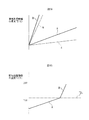
図4は、空気と燃料とを改質触媒において反応させて平衡に達したときの反応平衡温度TBと、空気と燃料のO/Cモル比との関係を示している。なお、図4の実線は、空気温が25℃のときの理論値を示している。図4の実線に示されるように、O/Cモル比=0.5のリッチ空燃比でもって部分酸化改質反応が行われたときには、平衡反応温度TBはほぼ830℃となる。なお、このときの実際の平衡反応温度TBは830℃よりも若干低くなるが、以下、平衡反応温度TBは図4の実線に示す値になるものとして、本発明による実施例について説明する。 FIG. 4 shows the relationship between the reaction equilibrium temperature TB when air and fuel are reacted in the reforming catalyst to reach equilibrium, and the O 2 / C molar ratio of air and fuel. In addition, the continuous line of FIG. 4 has shown the theoretical value when air temperature is 25 degreeC. As shown by the solid line in FIG. 4, when the partial oxidation reforming reaction is performed with a rich air-fuel ratio of O 2 / C molar ratio = 0.5, the equilibrium reaction temperature TB is approximately 830 ° C. Note that the actual equilibrium reaction temperature TB at this time is slightly lower than 830 ° C., but the embodiment according to the present invention will be described below assuming that the equilibrium reaction temperature TB is a value shown by the solid line in FIG.

一方、図3(a)の完全酸化反応の反応式からわかるように、O/Cモル比=1.4575のときに空気と燃料との比が理論空燃比となり、図4に示されるように、反応平衡温度TBは、空気と燃料との比が理論空燃比になったときに最も高くなる。O/Cモル比が0.5と1.4575との間では、一部では部分酸化改質反応が行われ、一部では完全酸化反応が行われる。この場合、O/Cモル比が大きくなるほど、部分酸化改質反応が行われる割合に比べて完全酸化反応が行われる割合が大きくなるので、O/Cモル比が大きくなるほど、反応平衡温度TBが高くなる。 On the other hand, as can be seen from the reaction formula of the complete oxidation reaction in FIG. 3A, the ratio of air to fuel becomes the stoichiometric air-fuel ratio when the O 2 / C molar ratio = 1.4575, as shown in FIG. Moreover, the reaction equilibrium temperature TB becomes the highest when the ratio of air to fuel becomes the stoichiometric air-fuel ratio. When the O 2 / C molar ratio is between 0.5 and 1.4575, a partial oxidation reforming reaction is performed in part, and a complete oxidation reaction is performed in part. In this case, as the O 2 / C molar ratio increases, the rate at which the complete oxidation reaction is performed is higher than the rate at which the partial oxidation reforming reaction is performed. Therefore, the reaction equilibrium temperature increases as the O 2 / C molar ratio increases. TB becomes high.

一方、図5は、炭素原子1個当りの生成分子(HおよびCO)の個数とO/Cモル比との関係を示している。上述したように、O/Cモル比が0.5よりも大きくなるほど、部分酸化改質反応が行われる割合が減少する。従って、図5に示されるように、O/Cモル比が0.5よりも大きくなるほど、HおよびCOの生成量が減少する。なお、図5には記載していないが、O/Cモル比が0.5よりも大きくなると、図3(a)に示される完全酸化反応によって、COとHOの生成量は増大する。ところで、図5は、図3(d)に示される水性ガスシフト反応が生じないと仮定した場合のHおよびCOの生成量を示している。しかしながら、実際には部分酸化改質反応によって生成されたCOと完全酸化反応にとって生成されたHOとにより図3(d)に示される水性ガスシフト反応が生じ、この水性ガスシフト反応によっても、水素が生成される。 On the other hand, FIG. 5 shows the relationship between the number of generated molecules (H 2 and CO) per carbon atom and the O 2 / C molar ratio. As described above, as the O 2 / C molar ratio becomes larger than 0.5, the rate at which the partial oxidation reforming reaction is performed decreases. Therefore, as shown in FIG. 5, the amount of H 2 and CO generated decreases as the O 2 / C molar ratio is greater than 0.5. Although not shown in FIG. 5, when the O 2 / C molar ratio is larger than 0.5, the production amounts of CO 2 and H 2 O are increased by the complete oxidation reaction shown in FIG. Increase. Incidentally, FIG. 5 shows the production amounts of H 2 and CO when it is assumed that the water gas shift reaction shown in FIG. However, in reality, the water gas shift reaction shown in FIG. 3D is caused by CO generated by the partial oxidation reforming reaction and H 2 O generated for the complete oxidation reaction. Is generated.

さて、上述したように、O/Cモル比が0.5よりも大きくなるほど、HおよびCOの生成量が減少する。一方、図5に示されるように、O/Cモル比が0.5よりも小さくなると、反応し得ない余剰の炭素Cが増大する。この余剰の炭素Cは改質用触媒の基体の細孔内に付積し、いわゆる、コーキングを起こす。コーキングを起こすと改質用触媒の改質能力が著しく低下する。従って、コーキングを起こすのを回避するために、O/Cモル比は0.5よりも小さくさせないようにする必要がある。また、図5からわかるように、余剰の炭素Cが生じない範囲で、水素の生成量が最大となるのは、O/Cモル比が0.5のときである。従って、本発明の実施例では、水素を生成するために部分酸化改質反応が行われるときには、コーキングを起こすのを回避しつつ、水素を最も効率よく生成しうるように、O/Cモル比が、原則0.5とされる。 As described above, the amount of H 2 and CO produced decreases as the O 2 / C molar ratio is greater than 0.5. On the other hand, as shown in FIG. 5, when the O 2 / C molar ratio is smaller than 0.5, surplus carbon C that cannot be reacted increases. This surplus carbon C accumulates in the pores of the base of the reforming catalyst and causes so-called coking. When coking occurs, the reforming ability of the reforming catalyst is significantly reduced. Therefore, in order to avoid causing coking, the O 2 / C molar ratio should not be made smaller than 0.5. Further, as can be seen from FIG. 5, the generation amount of hydrogen is maximized when the O 2 / C molar ratio is 0.5 within the range where no surplus carbon C is generated. Therefore, in the embodiment of the present invention, when a partial oxidation reforming reaction is performed to generate hydrogen, O 2 / C mole is generated so that hydrogen can be generated most efficiently while avoiding coking. The ratio is in principle 0.5.

一方、O/Cモル比が、理論空燃比であるO/Cモル比=1.4575よりも大きくされても完全酸化反応が行われるが、O/Cモル比が大きくなるほど昇温すべき空気量が増大する。従って、図4に示されるように、O/Cモル比が、理論空燃比を示すO/Cモル比=1.4575よりも大きくされると、O/Cモル比が大きくなるほど、反応平衡温度TBが低下する。この場合、例えば、O/Cモル比が2.6のリーン空燃比にされると、空気温が25℃である場合には、反応平衡温度TBはほぼ920℃となる。 Meanwhile, O 2 / C molar ratio, is a stoichiometric air-fuel ratio O 2 / C molar ratio = 1.4575 even complete oxidation reaction is greater than can be performed, O 2 / C as the molar ratio increases heating The amount of air that should be increased. Therefore, as shown in FIG. 4, when the O 2 / C molar ratio is greater than the O 2 / C molar ratio indicating the theoretical air-fuel ratio = 1.4575, the larger the O 2 / C molar ratio is, The reaction equilibrium temperature TB decreases. In this case, for example, when the lean air-fuel ratio is 2.6 with an O 2 / C molar ratio, the reaction equilibrium temperature TB is approximately 920 ° C. when the air temperature is 25 ° C.

さて、前述したように、図1に示される熱、水素生成装置50の運転が開始されると、リーン空燃比のもとでバーナー燃焼が行われ、それにより改質用触媒54の温度が次第に上昇する。次いで、改質用触媒54の温度が、燃料を改質可能な温度に到達すると、通常は、空燃比がリーン空燃比からリッチ空燃比に切換えられ、改質用触媒54における燃料の改質作用が開始される。燃料の改質作用が開始されると、水素が生成される。図6には、改質用触媒54における反応が平衡状態になったときの改質用触媒54の酸化部54aおよび改質部54b内の温度分布を示している。なお、この図6は、外気温が25℃のときに、この外気が図2に示される低温空気流通路63を介して、バーナー57からバーナー燃焼室53内に供給された場合の温度分布を示している。   Now, as described above, when the operation of the heat and hydrogen generator 50 shown in FIG. 1 is started, burner combustion is performed under a lean air-fuel ratio, whereby the temperature of the reforming catalyst 54 gradually increases. To rise. Next, when the temperature of the reforming catalyst 54 reaches a temperature at which the fuel can be reformed, the air-fuel ratio is normally switched from the lean air-fuel ratio to the rich air-fuel ratio, and the fuel reforming action in the reforming catalyst 54 is achieved. Is started. When the reforming action of the fuel is started, hydrogen is generated. FIG. 6 shows the temperature distribution in the oxidizing portion 54a and the reforming portion 54b of the reforming catalyst 54 when the reaction in the reforming catalyst 54 reaches an equilibrium state. 6 shows the temperature distribution when the outside air is supplied from the burner 57 into the burner combustion chamber 53 via the low-temperature air flow passage 63 shown in FIG. 2 when the outside air temperature is 25 ° C. Show.

図6の実線は、バーナー57から供給される空気と燃料のO/Cモル比が0.5のときの改質用触媒54内の温度分布を示している。図6に示されるように、この場合には、改質用触媒54の酸化部54aでは、改質用触媒54内の温度は、残存酸素による酸化反応熱により下流側に向けて上昇する。燃焼ガスが改質用触媒54の酸化部54a内から改質部54b内に進む頃には、燃焼ガス中の残存酸素は消滅し、改質用触媒54の改質部54bでは燃料の改質作用が行われる。この改質反応は吸熱反応であり、従って改質用触媒54内の温度は、改質作用が進むに従って、即ち、改質用触媒54の下流側に向けて低下する。このときの改質用触媒54の下流側端面の温度は830℃であり、図4に示されるO/Cモル比=0.5のときの反応平衡温度TBに一致する。 The solid line in FIG. 6 shows the temperature distribution in the reforming catalyst 54 when the O 2 / C molar ratio of air and fuel supplied from the burner 57 is 0.5. As shown in FIG. 6, in this case, in the oxidation portion 54a of the reforming catalyst 54, the temperature in the reforming catalyst 54 rises toward the downstream side due to the heat of oxidation reaction due to residual oxygen. When the combustion gas advances from the oxidizing portion 54a of the reforming catalyst 54 into the reforming portion 54b, the remaining oxygen in the combustion gas disappears, and the reforming portion 54b of the reforming catalyst 54 reforms the fuel. The action is performed. This reforming reaction is an endothermic reaction, and therefore the temperature in the reforming catalyst 54 decreases as the reforming action proceeds, that is, toward the downstream side of the reforming catalyst 54. At this time, the temperature of the downstream end face of the reforming catalyst 54 is 830 ° C., which corresponds to the reaction equilibrium temperature TB when the O 2 / C molar ratio = 0.5 shown in FIG.

一方、図6には、バーナー57から供給される空気と燃料のO/Cモル比が2.6のリーン空燃比であるときの改質用触媒54内の温度分布が、破線で示されている。この場合も、改質用触媒54内の温度は、改質用触媒54の酸化部54a内では、燃料の酸化反応熱によって下流側に向けて上昇する。一方、この場合には、改質用触媒54の改質部54b内において改質作用は行われないので、改質用触媒54内の温度は、改質部54b内では一定に保持される。このときの改質用触媒54の下流側端面の温度は920℃であり、図4に示されるO/Cモル比=2.6のときの反応平衡温度TBに一致する。即ち、図4の反応平衡温度TBは、外気温が25℃のときにこの外気が図2に示される低温空気流通路63を介して、バーナー57からバーナー燃焼室53内に供給されたときの改質用触媒54の下流側端面の温度を示していることになる。 On the other hand, in FIG. 6, the temperature distribution in the reforming catalyst 54 when the O 2 / C molar ratio of the air and fuel supplied from the burner 57 is 2.6 is indicated by a broken line. ing. Also in this case, the temperature in the reforming catalyst 54 rises toward the downstream side in the oxidation portion 54a of the reforming catalyst 54 due to the oxidation reaction heat of the fuel. On the other hand, in this case, since the reforming action is not performed in the reforming part 54b of the reforming catalyst 54, the temperature in the reforming catalyst 54 is kept constant in the reforming part 54b. At this time, the temperature of the downstream end face of the reforming catalyst 54 is 920 ° C., which matches the reaction equilibrium temperature TB when the O 2 / C molar ratio shown in FIG. 4 is 2.6. That is, the reaction equilibrium temperature TB in FIG. 4 is obtained when the outside air is supplied from the burner 57 into the burner combustion chamber 53 via the low temperature air flow passage 63 shown in FIG. This indicates the temperature of the downstream end face of the reforming catalyst 54.

次に、図7を参照しつつ、改質触媒において燃料と反応する空気の温度を変化させたときの反応平衡温度TBについて説明する。図7は、図4と同様に、空気と燃料とを改質触媒において反応させて平衡に達したときの反応平衡温度TBと、空気と燃料のO/Cモル比との関係を示している。なお、図7においてTAは空気温を示しており、この図7には、図4において実線で示される反応平衡温度TBとO/Cモル比との関係が再度実線で示されている。図7には更に、空気温TAを225℃、425℃、625℃に変化させたときの反応平衡温度TBとO/Cモル比との関係が破線で示されている。図7から、空気温TAが上昇すると、O/Cモル比にかかわらず反応平衡温度TBが全体的に高くなることがわかる。 Next, the reaction equilibrium temperature TB when the temperature of the air that reacts with the fuel in the reforming catalyst is changed will be described with reference to FIG. FIG. 7 shows the relationship between the reaction equilibrium temperature TB when air and fuel are reacted in the reforming catalyst to reach equilibrium, and the O 2 / C molar ratio of air and fuel, as in FIG. Yes. In FIG. 7, TA indicates the air temperature. In FIG. 7, the relationship between the reaction equilibrium temperature TB and the O 2 / C molar ratio indicated by the solid line in FIG. 4 is again shown by the solid line. Further, in FIG. 7, the relationship between the reaction equilibrium temperature TB and the O 2 / C molar ratio when the air temperature TA is changed to 225 ° C., 425 ° C., and 625 ° C. is indicated by a broken line. FIG. 7 shows that when the air temperature TA rises, the reaction equilibrium temperature TB increases as a whole regardless of the O 2 / C molar ratio.

一方、本発明の実施例において用いられている改質用触媒54は、触媒温度が950℃以下であれば、大きな熱劣化を生じないことが確認されている。従って、本発明の実施例では、950℃が、改質用触媒54の熱劣化を回避しうる許容触媒温度TXとされており、この許容触媒温度TXが図4、図6および図7に示されている。図6からわかるように、空気温TAが25℃のときには、O/Cモル比が0.5のときでも、O/Cモル比が2.6のときでも、改質用触媒54における反応が平衡状態になったときの改質用触媒54の温度は、改質用触媒54のいずれの場所でも、許容触媒温度TX以下となる。従って、この場合には、実用上、熱劣化を問題とすることなく、改質用触媒54を使用し続けることができる。 On the other hand, it has been confirmed that the reforming catalyst 54 used in the examples of the present invention does not cause large thermal degradation when the catalyst temperature is 950 ° C. or lower. Therefore, in the embodiment of the present invention, 950 ° C. is the allowable catalyst temperature TX that can avoid the thermal deterioration of the reforming catalyst 54, and this allowable catalyst temperature TX is shown in FIGS. 4, 6, and 7. Has been. As can be seen from FIG. 6, when the air temperature TA is 25 ° C., even when the O 2 / C molar ratio is 0.5 or when the O 2 / C molar ratio is 2.6, The temperature of the reforming catalyst 54 when the reaction reaches an equilibrium state is equal to or lower than the allowable catalyst temperature TX at any location of the reforming catalyst 54. Therefore, in this case, the reforming catalyst 54 can be continuously used without causing a problem of thermal degradation in practice.

一方、図4からわかるように、空気温TAが25℃のときでも、O/Cモル比が0.5よりも少し大きくなると、改質用触媒54における反応が平衡状態になったときの改質用触媒54の下流側端面の温度、即ち、反応平衡温度TBは許容触媒温度TXを越えてしまい、O/Cモル比が2.6よりも少し小さくなると、改質用触媒54における反応が平衡状態になったときの改質用触媒54の下流側端面の温度は許容触媒温度TXを越えてしまう。従って、例えば、改質用触媒54における反応が平衡状態であるときに部分酸化改質反応を生じさせる場合、O/Cモル比を0.5よりも大きくすることもできるが、O/Cモル比を大きくし得る範囲は限られている。 On the other hand, as can be seen from FIG. 4, when the O 2 / C molar ratio is slightly larger than 0.5 even when the air temperature TA is 25 ° C., the reaction in the reforming catalyst 54 is in an equilibrium state. When the temperature of the downstream end face of the reforming catalyst 54, that is, the reaction equilibrium temperature TB exceeds the allowable catalyst temperature TX and the O 2 / C molar ratio is slightly smaller than 2.6, the reforming catalyst 54 The temperature of the downstream end face of the reforming catalyst 54 when the reaction reaches an equilibrium state exceeds the allowable catalyst temperature TX. Thus, for example, it may give rise to partial oxidation reforming reaction when the reaction in the reforming catalyst 54 is in equilibrium, although the O 2 / C molar ratio may be greater than 0.5, O 2 / The range in which the C molar ratio can be increased is limited.

一方、図7からわかるように、空気温TAが高くなると、改質用触媒54における反応が平衡状態になっているときに、O/Cモル比を0.5にしたとしても、改質用触媒54における反応が平衡状態になったときの改質用触媒54の下流側端面の温度は、許容触媒温度TXよりも高くなり、従って、改質用触媒54が熱劣化することになる。従って、空気温TAが高くなったときには、改質用触媒54における反応が平衡状態になっているときに、O/Cモル比を0.5とすることができない。そこで、本発明の実施例では、改質用触媒54における反応が平衡状態になったときには、空気温TAが25℃程度の低い温度とされ、空気温TAを25℃程度の低い温度に維持した状態で、O/Cモル比が0.5とされる。 On the other hand, as can be seen from FIG. 7, when the air temperature TA increases, the reforming catalyst 54 is in an equilibrium state, and even if the O 2 / C molar ratio is 0.5, the reforming is performed. The temperature of the downstream end face of the reforming catalyst 54 when the reaction in the reforming catalyst 54 reaches an equilibrium state becomes higher than the allowable catalyst temperature TX, and thus the reforming catalyst 54 is thermally deteriorated. Therefore, when the air temperature TA becomes high, the O 2 / C molar ratio cannot be made 0.5 when the reaction in the reforming catalyst 54 is in an equilibrium state. Therefore, in the embodiment of the present invention, when the reaction in the reforming catalyst 54 reaches an equilibrium state, the air temperature TA is set to a low temperature of about 25 ° C., and the air temperature TA is maintained at a low temperature of about 25 ° C. In the state, the O 2 / C molar ratio is set to 0.5.

以上説明したように、本発明の実施例では、熱、水素生成装置50の運転が開始されると、リーン空燃比のもとでバーナー燃焼が開始され、このリーン空燃比のもとでのバーナー燃焼は、改質用触媒54による改質作用が可能となるまで行われる。別の言い方をすると、本発明の実施例では、熱、水素生成装置50の始動後、改質用触媒54による改質作用が可能となるまでリーン空燃比のもとで熱、水素生成装置50の暖機運転が行われる。この場合、改質用触媒54の温度が700℃程度になると改質用触媒54による改質作用が可能となり、従って、本発明の実施例では、熱、水素生成装置50の始動後、改質用触媒54の温度が700℃になるまで、リーン空燃比のもとで熱、水素生成装置50の暖機運転が行われる。この間、熱、水素生成装置50において生成された燃焼ガスはガス流出室55のガス流出口74から流出せしめられ、次いで、供給通路51を介して、排気処理触媒13に供給される。次いで、改質用触媒による改質作用が可能になると、即ち、改質用触媒54の温度が700℃になると、通常は、空燃比がリーン空燃比からリッチ空燃比に切換えられ、部分酸化改質反応が行われる。部分酸化改質反応が行われると、改質用触媒44において熱および水素が生成される。これらの熱および水素はガス流出室55のガス流出口74から流出せしめられ、水素を含む燃焼ガスは、供給通路51を介して、排気処理触媒13に供給される。   As described above, in the embodiment of the present invention, when the operation of the heat and hydrogen generator 50 is started, burner combustion is started under the lean air-fuel ratio, and the burner under this lean air-fuel ratio is started. Combustion is performed until the reforming action by the reforming catalyst 54 becomes possible. In other words, in the embodiment of the present invention, after the heat and hydrogen generator 50 is started, the heat and hydrogen generator 50 under a lean air-fuel ratio until the reforming action by the reforming catalyst 54 becomes possible. Is warmed up. In this case, when the temperature of the reforming catalyst 54 reaches about 700 ° C., the reforming action by the reforming catalyst 54 becomes possible. Therefore, in the embodiment of the present invention, after the heat and the hydrogen generator 50 are started, the reforming is performed. Until the temperature of the catalyst 54 reaches 700 ° C., the warm-up operation of the heat and hydrogen generator 50 is performed under the lean air-fuel ratio. During this time, heat and combustion gas generated in the hydrogen generator 50 are discharged from the gas outlet 74 of the gas outlet chamber 55 and then supplied to the exhaust treatment catalyst 13 via the supply passage 51. Next, when the reforming action by the reforming catalyst becomes possible, that is, when the temperature of the reforming catalyst 54 reaches 700 ° C., the air-fuel ratio is normally switched from the lean air-fuel ratio to the rich air-fuel ratio, and the partial oxidation reforming is performed. A quality reaction takes place. When the partial oxidation reforming reaction is performed, heat and hydrogen are generated in the reforming catalyst 44. These heat and hydrogen are caused to flow out from the gas outlet 74 of the gas outflow chamber 55, and the combustion gas containing hydrogen is supplied to the exhaust treatment catalyst 13 through the supply passage 51.

次に、機関排気通路内に配置された排気処理触媒13による排気ガスの浄化作用について説明する。なお、前述したように、図1に示される例では、この排気処理触媒13はNO吸蔵還元触媒からなり、このNO吸蔵還元触媒13は、白金Pt,パラジウムPd,ロジウムRhのような貴金属と、カリウムK、ナトリウムNa、セシウムCsのようなアルカリ金属、或いは、バリウムBa、カルシウムCaのようなアルカリ土類金属とを担持している。このNO吸蔵還元触媒13は、NO吸蔵還元触媒13に流入する排気ガスの空燃比がリーンのときには排気ガス中に含まれるNOを吸蔵し、NO吸蔵還元触媒13に流入する排気ガスの空燃比がリッチにされるとNO吸蔵還元触媒13から吸蔵されたNOを放出するというNOの吸放出機能を有する。通常、排気ガスの空燃比はリーンとなっており、従って、排気ガス中に含まれるNOは、NO吸蔵還元触媒13に吸蔵される、即ち浄化される。 Next, the exhaust gas purification action by the exhaust treatment catalyst 13 disposed in the engine exhaust passage will be described. As described above, in the example shown in FIG. 1, the exhaust treatment catalyst 13 is composed of a NO X storage reduction catalyst, and the NO X storage reduction catalyst 13 is a noble metal such as platinum Pt, palladium Pd, rhodium Rh. And an alkali metal such as potassium K, sodium Na, and cesium Cs, or an alkaline earth metal such as barium Ba and calcium Ca. This the NO X storage reduction catalyst 13, the exhaust gas air-fuel ratio of the exhaust gas flowing into the NO X occluding and reducing catalyst 13 when the lean occludes NO X contained in the exhaust gas, flows into the NO X storage reduction catalyst 13 air-fuel ratio of has the absorption and release function of the NO X that emits NO X occluded from when it is made rich the NO X storage reduction catalyst 13. Normally, the air-fuel ratio of the exhaust gas is lean, and therefore NO X contained in the exhaust gas is stored in the NO X storage reduction catalyst 13, that is, purified.

一方、パティキュレートフィルタ14に担持されたNO選択還元触媒は、例えばCuゼオライトからなり、アンモニアの存在のもとでNOを還元する機能を有する。図1に示される実施例では、尿素供給弁17からNO選択還元触媒に尿素水が供給され、この尿素水から発生したアンモニアにより、NO吸蔵還元触媒13をすり抜けたNOがNO選択還元触媒において還元される、即ち浄化される。この場合、機関始動時に、NO吸蔵還元触媒13およびNO選択還元触媒によるNOの浄化作用を促進するには、NO吸蔵還元触媒13およびNO選択還元触媒をできるだけ早く活性化させる必要があり、そのためにはNO吸蔵還元触媒13およびNO選択還元触媒をできるだけ早く温度上昇させる必要がある。 On the other hand, the NO X selective reduction catalyst supported on the particulate filter 14 is made of, for example, Cu zeolite and has a function of reducing NO X in the presence of ammonia. In the embodiment shown in FIG. 1, urea water is supplied from the urea supply valve 17 to the NO X selective reduction catalyst, and NO X that has passed through the NO X storage reduction catalyst 13 by the ammonia generated from the urea water is selected as NO X. It is reduced or purified in the reduction catalyst. In this case, it is necessary to activate the NO X storage reduction catalyst 13 and the NO X selective reduction catalyst as soon as possible in order to promote the NO X purification action by the NO X storage reduction catalyst 13 and the NO X selective reduction catalyst when the engine is started. Therefore, it is necessary to raise the temperature of the NO X storage reduction catalyst 13 and the NO X selective reduction catalyst as quickly as possible.

そこで、本発明の実施例では、機関始動時に、排気処理触媒13の温度を目標暖機温度まで、すみやかに上昇させるために、機関の始動と同時に、熱、水素生成装置50の運転が開始され、熱、水素生成装置50から排気処理触媒13に供給された熱および水素、又は熱によって排気処理触媒13の暖機作用を促進するようにしている。なお、この場合、本発明の実施例では、NO吸蔵還元触媒13の暖機作用を促進することによってNO吸蔵還元触媒13から流出する排気ガスの温度を上昇させ、それによって、選択還元触媒の温度が上昇せしめられる。次に、図8Aおよび図8Bを参照しつつ、この熱、水素生成装置50による排気処理触媒13の暖機促進作用について説明する。 Therefore, in the embodiment of the present invention, at the time of starting the engine, in order to quickly raise the temperature of the exhaust treatment catalyst 13 to the target warm-up temperature, the operation of the heat and hydrogen generator 50 is started simultaneously with the start of the engine. The warming-up action of the exhaust treatment catalyst 13 is promoted by heat and heat and hydrogen supplied from the hydrogen generator 50 to the exhaust treatment catalyst 13 or heat. In this case, in the embodiment of the present invention, it increases the temperature of the exhaust gas flowing out from the NO X storage reduction catalyst 13 by promoting warm-up action of the NO X occluding and reducing catalyst 13, whereby the selective reduction catalyst The temperature of is increased. Next, with reference to FIG. 8A and FIG. 8B, the heat and warming promotion action of the exhaust treatment catalyst 13 by the hydrogen generator 50 will be described.

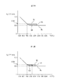
図8Aおよび図8Bは、排気処理触媒13が、白金Pt,パラジウムPd,ロジウムRhのような貴金属を担持している場合において、熱、水素生成装置50により排気処理触媒13の暖機を行なったときの排気処理触媒13の温度TDの変化を示している。なお、図8Aおよび図8Bにおいて、横軸は時間経過を示している。これら図8Aおよび図8Bでは、説明をわかり易くするために、機関から排出された排気ガスによる排気処理触媒13の暖機作用については無視している。また、図8Bにおいて、TDは貴金属が活性化する温度を示しており、図8Bに示す例では、この貴金属が活性化する温度TDは110℃とされている。なお、以下、この貴金属が活性化する温度TDを、排気処理触媒13の活性化温度TDと称する。 8A and 8B show that the exhaust treatment catalyst 13 is warmed up by the heat and hydrogen generator 50 when the exhaust treatment catalyst 13 carries a noble metal such as platinum Pt, palladium Pd, and rhodium Rh. The change of the temperature TD of the exhaust treatment catalyst 13 is shown. In FIGS. 8A and 8B, the horizontal axis indicates the passage of time. In FIG. 8A and FIG. 8B, the warm-up action of the exhaust treatment catalyst 13 by the exhaust gas discharged from the engine is ignored for easy understanding. In FIG. 8B, TD 0 indicates the temperature at which the noble metal is activated. In the example shown in FIG. 8B, the temperature TD 0 at which the noble metal is activated is 110 ° C. Hereinafter, the temperature TD 0 This noble metal is activated, referred to as the activation temperature TD 0 of the exhaust treatment catalyst 13.

さて、図3からわかるように、完全酸化反応と、部分酸化改質反応とを比較すると、完全酸化反応の方が部分酸化改質反応に比べて、はるかに発熱量が大きく、従って、使用燃料量が同一である場合には、排気処理触媒13に供給される熱量は、熱、水素生成装置50において完全酸化反応が行われているときの方が、熱、水素生成装置50において部分酸化改質反応が行われてときに比べて、はるかに大きい。図8Aには、使用燃料量が同一の場合において、O/Cモル比=2.6でもって完全酸化反応が行われたときの生成熱により排気処理触媒13が暖機された場合の排気処理触媒13の温度変化が実線Aで示されており、O/Cモル比=0.5でもって部分酸化改質反応が行われたときの生成熱のみにより排気処理触媒13が暖機された場合の排気処理触媒13の温度変化が破線aで示されている。実線Aと破線aとを比較するとわかるように、熱、水素生成装置50において生成された熱のみにより排気処理触媒13が暖機された場合の排気処理触媒13の温度TDの上昇速度は、完全酸化反応の方が部分酸化改質反応に比べて、高いことがわかる。 Now, as can be seen from FIG. 3, when the complete oxidation reaction and the partial oxidation reforming reaction are compared, the complete oxidation reaction has a much larger calorific value than the partial oxidation reforming reaction, and therefore, the fuel used. When the amounts are the same, the amount of heat supplied to the exhaust treatment catalyst 13 is equal to that when the complete oxidation reaction is performed in the heat and hydrogen generator 50. Much greater than when quality reactions are taking place. FIG. 8A shows the exhaust when the exhaust treatment catalyst 13 is warmed up by the generated heat when the complete oxidation reaction is performed with the O 2 / C molar ratio = 2.6 in the case where the amount of fuel used is the same. The temperature change of the treatment catalyst 13 is indicated by a solid line A, and the exhaust treatment catalyst 13 is warmed up only by the heat generated when the partial oxidation reforming reaction is performed with an O 2 / C molar ratio = 0.5. The temperature change of the exhaust treatment catalyst 13 is shown by a broken line a. As can be seen by comparing the solid line A and the broken line a, the rate of increase in the temperature TD of the exhaust treatment catalyst 13 when the exhaust treatment catalyst 13 is warmed up only by heat and heat generated in the hydrogen generator 50 is completely It can be seen that the oxidation reaction is higher than the partial oxidation reforming reaction.

一方、排気処理触媒13の暖機時に、排気処理触媒13に水素が供給され、貴金属上において水素の酸化反応が行われると、水素の酸化反応熱によって、排気処理触媒13の温度TDは急速に上昇する。図8Aの破線bは、同一の使用燃料量のもとで、O/Cモル比=0.5でもって部分酸化改質反応が行われたときの生成水素のみにより排気処理触媒13が暖機された場合の排気処理触媒13の温度変化を示しており、図8Aの実線Bは、同一の使用燃料量のもとで、O/Cモル比=0.5でもって部分酸化改質反応が行われたときの生成熱および生成水素により排気処理触媒13が暖機された場合の排気処理触媒13の温度変化を示している。図8Aにおいて実線Aと実線Bとを比較するとわかるように、水素による排気処理触媒13の暖機作用も行われている場合には、排気処理触媒13の温度TDの上昇速度は、部分酸化改質反応の方が完全酸化反応に比べて、はるかに高いことがわかる。 On the other hand, when the exhaust treatment catalyst 13 is warmed up, when hydrogen is supplied to the exhaust treatment catalyst 13 and an oxidation reaction of hydrogen is performed on the noble metal, the temperature TD of the exhaust treatment catalyst 13 is rapidly increased due to the oxidation reaction heat of hydrogen. To rise. The broken line b in FIG. 8A shows that the exhaust treatment catalyst 13 is warmed only by the generated hydrogen when the partial oxidation reforming reaction is performed with the O 2 / C molar ratio = 0.5 under the same amount of fuel used. FIG. 8A shows the change in temperature of the exhaust treatment catalyst 13 when it is operated, and the solid line B in FIG. 8A shows the partial oxidation reforming with the O 2 / C molar ratio = 0.5 under the same amount of fuel used. A temperature change of the exhaust treatment catalyst 13 when the exhaust treatment catalyst 13 is warmed up by generated heat and produced hydrogen when the reaction is performed is shown. As can be seen by comparing the solid line A and the solid line B in FIG. 8A, when the warming-up action of the exhaust treatment catalyst 13 by hydrogen is also performed, the rate of increase in the temperature TD of the exhaust treatment catalyst 13 is the partial oxidation modification. It can be seen that the quality reaction is much higher than the complete oxidation reaction.

即ち、熱、水素生成装置50において生成された燃焼ガス熱に一部は、この燃焼ガスが供給導管51内を流れる間に外部に逃げ、しかも、この燃焼ガス熱は、熱伝達によって排気処理触媒13に供給されるにすぎないので、実際に排気処理触媒13の加熱のために用いられる熱量はそれほど多くはない。これに対し、熱、水素生成装置50において生成された水素は、排気処理触媒13に到達するまで消費されず、排気処理触媒13自体が水素の酸化反応熱によって直接加熱されるために、水素の酸化反応熱によって、排気処理触媒13は急速に昇温せしめられることになる。   That is, part of the heat and combustion gas heat generated in the hydrogen generator 50 escapes to the outside while the combustion gas flows through the supply conduit 51, and the combustion gas heat is exhausted by the heat transfer. Therefore, the amount of heat actually used for heating the exhaust treatment catalyst 13 is not so much. On the other hand, the heat and hydrogen generated in the hydrogen generator 50 are not consumed until reaching the exhaust treatment catalyst 13, and the exhaust treatment catalyst 13 itself is directly heated by the oxidation reaction heat of hydrogen. The temperature of the exhaust treatment catalyst 13 is rapidly raised by the oxidation reaction heat.

ところで、排気処理触媒13の温度TDが、図8Bに示される排気処理触媒13の活性化温度TDよりも低いときには、排気処理触媒13に水素が供給されたとしても、貴金属上において水素の酸化反応は行われず、従って、このときには水素の酸化反応による酸化反応熱は発生しない。従って、排気処理触媒13の温度TDが、排気処理触媒13の活性化温度TDよりも低いときには、図8Aからわかるように、熱、水素生成装置50において完全酸化反応が行われているときの方が、熱、水素生成装置50において部分酸化改質反応が行われてときに比べて、排気処理触媒13の昇温速度が、はるかに大きくなる。 By the way, when the temperature TD of the exhaust treatment catalyst 13 is lower than the activation temperature TD 0 of the exhaust treatment catalyst 13 shown in FIG. 8B, even if hydrogen is supplied to the exhaust treatment catalyst 13, oxidation of hydrogen on the noble metal is performed. The reaction is not performed, and therefore, no heat of oxidation reaction due to the oxidation reaction of hydrogen occurs at this time. Therefore, when the temperature TD of the exhaust treatment catalyst 13 is lower than the activation temperature TD 0 of the exhaust treatment catalyst 13, as can be seen from FIG. 8A, when the complete oxidation reaction is performed in the heat and hydrogen generator 50. However, the temperature increase rate of the exhaust treatment catalyst 13 is much higher than when the partial oxidation reforming reaction is performed in the heat and hydrogen generator 50.

これに対し、排気処理触媒13の温度TDが、排気処理触媒13の活性化温度TDよりも高いときに、熱、水素生成装置50において部分酸化改質反応が行われ、それにより排気処理触媒13に水素が供給されると、水素の酸化反応熱によって、排気処理触媒13は急速に昇温せしめられる。従って、排気処理触媒13を、できるだけ早く昇温させるためには、排気処理触媒13の温度TDが、排気処理触媒13の活性化温度TDよりも低いときには、図8Bにおいて実線Aで示されるように、熱、水素生成装置50において完全酸化反応を行うことにより熱のみを排気処理触媒13に供給し、排気処理触媒13の温度TDが、排気処理触媒13の活性化温度TDよりも高くなったときには、図8Bにおいて実線Bで示されるように、熱、水素生成装置50において部分酸化改質反応を行うことにより熱および水素を排気処理触媒13に供給することが好ましいことがわかる。 On the other hand, when the temperature TD of the exhaust treatment catalyst 13 is higher than the activation temperature TD 0 of the exhaust treatment catalyst 13, a partial oxidation reforming reaction is performed in the heat and hydrogen generation device 50, thereby the exhaust treatment catalyst. When hydrogen is supplied to 13, the temperature of the exhaust treatment catalyst 13 is rapidly raised by the heat of oxidation reaction of hydrogen. Therefore, in order to raise the temperature of the exhaust treatment catalyst 13 as soon as possible, when the temperature TD of the exhaust treatment catalyst 13 is lower than the activation temperature TD 0 of the exhaust treatment catalyst 13, as shown by the solid line A in FIG. In addition, only the heat is supplied to the exhaust treatment catalyst 13 by performing a complete oxidation reaction in the heat and hydrogen generator 50, and the temperature TD of the exhaust treatment catalyst 13 becomes higher than the activation temperature TD 0 of the exhaust treatment catalyst 13. 8B, it is understood that heat and hydrogen are preferably supplied to the exhaust treatment catalyst 13 by performing a partial oxidation reforming reaction in the heat and hydrogen generator 50, as indicated by a solid line B in FIG. 8B.

しかしながら、実際には、常に、図8Bに示されるように、排気処理触媒13の温度TDが活性化温度TDになったときに、熱、水素生成装置50における反応を、完全酸化反応から部分酸化改質反応に切換えるのは困難である。そこで、本発明の実施例では、熱、水素生成装置50の始動後、改質用触媒54による改質作用が可能となったときに、排気処理触媒13の温度TDが、図8Bに示される排気処理触媒13の活性化温度TDよりも高いときには、熱、水素生成装置50における反応を、ただちに、完全酸化反応から部分酸化改質反応に切換え、熱、水素生成装置50の始動後、改質用触媒54による改質作用が可能となったときに、排気処理触媒13の温度TDが活性化温度TDよりも低いときには、排気処理触媒13の温度TDが活性化温度TDよりも高くなるまで、熱、水素生成装置50において完全酸化反応を続行させ、排気処理触媒13の温度TDが活性化温度TDよりも高くなったときに、熱、水素生成装置50における反応を、完全酸化反応から部分酸化改質反応に切換えるようにしている。このようにすることによって、排気処理触媒13の暖機を最も早めることができる。 However, in practice, as shown in FIG. 8B, when the temperature TD of the exhaust treatment catalyst 13 reaches the activation temperature TD 0 , the reaction in the heat and hydrogen generator 50 is always partially performed from the complete oxidation reaction. It is difficult to switch to the oxidation reforming reaction. Therefore, in the embodiment of the present invention, the temperature TD of the exhaust treatment catalyst 13 is shown in FIG. 8B when the reforming action by the reforming catalyst 54 becomes possible after the heat and hydrogen generator 50 is started. When the activation temperature TD 0 of the exhaust treatment catalyst 13 is higher, the heat and the reaction in the hydrogen generator 50 are immediately switched from the complete oxidation reaction to the partial oxidation reforming reaction. When the reforming action by the quality catalyst 54 becomes possible, if the temperature TD of the exhaust treatment catalyst 13 is lower than the activation temperature TD 0 , the temperature TD of the exhaust treatment catalyst 13 is higher than the activation temperature TD 0. Until the temperature and TD of the exhaust treatment catalyst 13 becomes higher than the activation temperature TD 0 , the reaction in the heat and hydrogen generator 50 is completely completed. The oxidation reaction is switched to the partial oxidation reforming reaction. By doing so, warming up of the exhaust treatment catalyst 13 can be accelerated most.

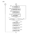
次に、図9を参照しつつ、図2に示される熱、水素生成装置50による熱、水素生成方法の概要について説明する。なお、この図9は、熱、水素生成装置50の暖機運転が完了して改質用触媒54による改質作用が可能になったときに、排気処理触媒13の温度TDが予め設定された活性化温度TD以上である場合を示している。また、この図9には、グロープラグ68の作動状態、バーナー57からの供給空気量、バーナー57からの供給燃料量、反応せしめられる空気と燃料のO/Cモル比、バーナー57から供給される空気の供給空気温、改質用触媒54の下流側端面の温度TCおよび排気処理触媒13の温度TDが示されている。なお、図9等に示される改質用触媒54の下流側端面の温度TCに対する各目標温度および改質用触媒54の温度に対する各目標温度は、理論値であり、本発明による実施例では、前述したように、例えば、実際の平衡反応温度TBは、目標温度である830℃よりも若干低くなる。これらの各目標温度は、熱、水素生成装置50の構造等によって変化し、従って、実際には、実験を行って、熱、水素生成装置50の構造に応じた最適の各目標温度を予め定める必要がある。 Next, the outline of the heat shown in FIG. 2, the heat generated by the hydrogen generator 50, and the hydrogen generation method will be described with reference to FIG. In FIG. 9, the temperature TD of the exhaust treatment catalyst 13 is set in advance when the warming-up operation of the heat and hydrogen generator 50 is completed and the reforming action by the reforming catalyst 54 becomes possible. The case where the activation temperature TD is 0 or more is shown. Further, in FIG. 9, the operating state of the glow plug 68, the amount of air supplied from the burner 57, the amount of fuel supplied from the burner 57, the O 2 / C molar ratio of the reacted air and fuel, supplied from the burner 57. The air supply air temperature, the temperature TC of the downstream end face of the reforming catalyst 54, and the temperature TD of the exhaust treatment catalyst 13 are shown. Note that each target temperature with respect to the temperature TC of the downstream end face of the reforming catalyst 54 and each target temperature with respect to the temperature of the reforming catalyst 54 shown in FIG. 9 and the like are theoretical values, and in the embodiment according to the present invention, As described above, for example, the actual equilibrium reaction temperature TB is slightly lower than the target temperature of 830 ° C. Each of these target temperatures varies depending on heat, the structure of the hydrogen generator 50, etc. Therefore, in practice, an optimum target temperature corresponding to the structure of the heat, the hydrogen generator 50 is determined in advance. There is a need.

機関が始動されると、熱、水素生成装置50が同時に始動される。熱、水素生成装置50が始動されると、グロープラグ68がオンとされ、次いで、空気が高温空気流通路62を介してバーナー燃焼室53内に供給される。この場合、図9において、破線で示されるように、空気が高温空気流通路62を介してバーナー燃焼室53内に供給された後、グロープラグ68をオンにすることもできる。次いで、バーナー57から燃料が噴射される。バーナー57から噴射された燃料がグロープラグ68により着火されると、燃料量が増量されると共に、反応せしめられる空気と燃料のO/Cモル比が4.0から3.0に減少され、バーナー燃焼室53内においてバーナー燃焼が開始される。燃料の供給が開始されてから燃料が着火されるまでの期間は、HCの発生量を極力抑えるために、空燃比がリーン空燃比とされている。 When the engine is started, the heat and hydrogen generator 50 is started simultaneously. When the heat and hydrogen generator 50 is started, the glow plug 68 is turned on, and then air is supplied into the burner combustion chamber 53 via the hot air flow passage 62. In this case, as shown by a broken line in FIG. 9, after the air is supplied into the burner combustion chamber 53 via the high-temperature air flow passage 62, the glow plug 68 can be turned on. Next, fuel is injected from the burner 57. When the fuel injected from the burner 57 is ignited by the glow plug 68, the amount of fuel is increased and the O 2 / C molar ratio of air to fuel to be reacted is reduced from 4.0 to 3.0, Burner combustion is started in the burner combustion chamber 53. In the period from the start of fuel supply until the fuel is ignited, the air-fuel ratio is set to the lean air-fuel ratio in order to suppress the amount of HC generated as much as possible.

次いで、バーナー燃焼、即ち、リーン空燃比による完全酸化反応が続行され、それにより、改質用触媒54の温度が徐々に上昇せしめられる。一方、バーナー燃焼が開始されると、改質用触媒54を通ってガス流出室55内に流出するガスの温度が次第に上昇する。従って、このガスにより熱交換部62aにおいて加熱される空気の温度も次第に上昇し、その結果、高温空気流通路62からバーナー燃焼室53内に供給される空気の温度が次第に上昇する。それにより、改質用触媒54の暖機が促進されることになる。このようにリーン空燃比のもとで行われる改質用触媒54の暖機を、本発明の実施例では、図9に示されるように1次暖機、又は、熱、水素生成装置50の暖機と称している。なお、図9に示される例では、この1次暖機運転の間に、供給空気量と燃料量が増量されている。   Next, burner combustion, that is, a complete oxidation reaction with a lean air-fuel ratio is continued, whereby the temperature of the reforming catalyst 54 is gradually raised. On the other hand, when the burner combustion is started, the temperature of the gas flowing out into the gas outflow chamber 55 through the reforming catalyst 54 gradually increases. Therefore, the temperature of the air heated in the heat exchanging portion 62a by this gas also gradually increases, and as a result, the temperature of the air supplied from the high temperature air flow passage 62 into the burner combustion chamber 53 gradually increases. As a result, warm-up of the reforming catalyst 54 is promoted. As described above, in the embodiment of the present invention, the warming-up of the reforming catalyst 54 performed under the lean air-fuel ratio is performed as shown in FIG. This is called warm-up. In the example shown in FIG. 9, the supply air amount and the fuel amount are increased during the primary warm-up operation.

この1次暖機運転、即ち、熱、水素生成装置50の暖機運転は、改質用触媒54において燃料の改質が可能になるまで続行される。図9に示される例では、改質用触媒54の下流側端面の温度TCが700℃になると、改質用触媒54において燃料の改質が可能になったと判断され、従って、図9に示される例では、1次暖機運転、即ち、熱、水素生成装置50の暖機運転は、改質用触媒54の下流側端面の温度TCが700℃になるまで続行される。なお、図9に示される例では、水素生成装置50の運転が開始されてから改質用触媒54の1次暖機が完了するまで、即ち、水素生成装置50の運転が開始されてから熱、水素生成装置50の暖機が完了するまで、図9に示されるように、反応せしめられる空気と燃料のO/Cモル比が3.0から4.0とされ、リーン空燃比による完全酸化反応が行われている。無論、このときには、改質用触媒54の温度は許容触媒温度TXよりもかなり低いので、反応せしめられる空気と燃料のO/Cモル比を、例えば、2.0から3.0のような理論空燃比に近いO/Cモル比とすることもできる。 This primary warm-up operation, that is, the warm-up operation of the heat and hydrogen generator 50 is continued until the reforming of the fuel in the reforming catalyst 54 becomes possible. In the example shown in FIG. 9, when the temperature TC at the downstream end face of the reforming catalyst 54 reaches 700 ° C., it is determined that the reforming catalyst 54 can reform the fuel. In this example, the primary warm-up operation, that is, the warm-up operation of the heat and hydrogen generator 50 is continued until the temperature TC of the downstream end face of the reforming catalyst 54 reaches 700 ° C. In the example shown in FIG. 9, the operation until the primary warm-up of the reforming catalyst 54 is completed after the operation of the hydrogen generator 50 is started, that is, after the operation of the hydrogen generator 50 is started. Until the warming-up of the hydrogen generator 50 is completed, as shown in FIG. 9, the O 2 / C molar ratio of the air to be reacted and the fuel is changed from 3.0 to 4.0. An oxidation reaction is taking place. Of course, since the temperature of the reforming catalyst 54 is considerably lower than the allowable catalyst temperature TX at this time, the O 2 / C molar ratio of air and fuel to be reacted is set to, for example, 2.0 to 3.0. An O 2 / C molar ratio close to the theoretical air-fuel ratio can also be set.

一方、図9に示されるように、機関が始動されると、排気処理触媒13の温度TDは、ただちに少し上昇する。次いで、図9に示される例では、1次暖機運転、即ち、熱、水素生成装置50の暖機運転が行われている間、排気処理触媒13の温度TDは少しずつ上昇し、排気処理触媒13の温度TDは、1次暖機運転、即ち、熱、水素生成装置50の暖機運転が行われている間に、予め設定された活性化温度TDを越える。このように排気処理触媒13の温度TDが予め設定された活性化温度TDを越えたとしても、熱、水素生成装置50ではリーン空燃比による完全酸化反応が続行される。次いで、排気処理触媒13の温度TDは更に少しずつ上昇し、図9に示される例では、改質用触媒54の下流側端面の温度TCが700℃になったときには、排気処理触媒13の温度TDは予め設定された活性化温度TD以上になっている。 On the other hand, as shown in FIG. 9, when the engine is started, the temperature TD of the exhaust treatment catalyst 13 immediately rises slightly. Next, in the example shown in FIG. 9, the temperature TD of the exhaust treatment catalyst 13 gradually increases during the primary warm-up operation, that is, the warm-up operation of the heat and hydrogen generator 50, and the exhaust treatment is performed. The temperature TD of the catalyst 13 exceeds the preset activation temperature TD 0 while the primary warm-up operation, that is, the warm-up operation of the heat and hydrogen generator 50 is performed. Thus, even if the temperature TD of the exhaust treatment catalyst 13 exceeds the preset activation temperature TD 0 , the heat and hydrogen generator 50 continues the complete oxidation reaction with the lean air-fuel ratio. Next, the temperature TD of the exhaust treatment catalyst 13 further increases little by little. In the example shown in FIG. 9, when the temperature TC of the downstream end face of the reforming catalyst 54 reaches 700 ° C., the temperature of the exhaust treatment catalyst 13 is increased. TD is in a set activation temperature TD 0 or more in advance.

次いで、改質用触媒54の下流側端面の温度TCが700℃になると、改質用触媒54において燃料の改質が可能になったと判断される。このとき、排気処理触媒13の温度TDは予め設定された活性化温度TD以上となっているので、水素を生成するための部分酸化改質反応が開始される。本発明の実施例では、このとき、図9に示されるように、まず初めに2次暖機運転が行われ、このとき、排気処理触媒13の温度TDを目標暖機温度まで上昇させるのに必要な熱、水素生成装置50の出力熱量(kW)の要求値が算出され、この出力熱量(kW)の要求出力熱量を発生させるのに必要な目標供給燃料量が算出されて、供給燃料量がこの目標供給燃料量とされる。次いで、2次暖機運転が完了すると通常運転が行われる。この2次暖機運転は、水素を生成しながら改質用触媒54の温度を更に上昇させるために行われる。2次暖機運転が開始されると、熱、水素生成装置50において生成された熱および水素か排気処理触媒13に供給され、この結果、図9に示されるように、排気処理触媒13の温度TDは急速に上昇する。 Next, when the temperature TC at the downstream end face of the reforming catalyst 54 reaches 700 ° C., it is determined that the reforming catalyst 54 can reform the fuel. At this time, since the temperature TD of the exhaust treatment catalyst 13 is equal to or higher than the preset activation temperature TD 0 , the partial oxidation reforming reaction for generating hydrogen is started. In the embodiment of the present invention, at this time, as shown in FIG. 9, first, the secondary warm-up operation is performed. At this time, the temperature TD of the exhaust treatment catalyst 13 is increased to the target warm-up temperature. Necessary heat, a required value of the output heat quantity (kW) of the hydrogen generator 50 is calculated, a target supply fuel quantity required to generate the required output heat quantity of this output heat quantity (kW) is calculated, and the supplied fuel quantity Is the target supply fuel amount. Next, when the secondary warm-up operation is completed, normal operation is performed. This secondary warm-up operation is performed to further raise the temperature of the reforming catalyst 54 while generating hydrogen. When the secondary warm-up operation is started, the heat, the heat generated in the hydrogen generator 50 and hydrogen are supplied to the exhaust treatment catalyst 13, and as a result, as shown in FIG. TD rises rapidly.

一方、この2次暖機運転は、改質用触媒54の下流側端面の温度TCが、反応平衡温度TBに達するまで続行され、改質用触媒54の下流側端面の温度TCが、反応平衡温度TBに達すると通常運転に移行する。なお、2次暖機運転が開始されるときには、排気処理触媒13の温度TDを目標暖機温度まで上昇させるのに必要な熱、水素生成装置50の出力熱量(kW)の要求値が算出される。この場合、この出力熱量(kW)の要求値は、基本的には、排気処理触媒13の目標暖機温度と現在の排気ガス温TDとの温度差と、機関から排出される排気ガス量との積に基づいて算出される。熱、水素生成装置50の出力熱量(kW)の要求値が算出されると、この出力熱量(kW)の要求出力熱量を発生させるのに必要な目標供給燃料量が算出され、図9に示されるように、2次暖機運転から通常運転に移行するときに、バーナー57からの供給燃料量がこの目標供給燃料量まで増大される。   On the other hand, the secondary warm-up operation is continued until the temperature TC of the downstream end face of the reforming catalyst 54 reaches the reaction equilibrium temperature TB, and the temperature TC of the downstream end face of the reforming catalyst 54 is changed to the reaction equilibrium. When the temperature TB is reached, normal operation is started. When the secondary warm-up operation is started, the required value for the heat required to raise the temperature TD of the exhaust treatment catalyst 13 to the target warm-up temperature and the output heat amount (kW) of the hydrogen generator 50 are calculated. The In this case, the required value of the output heat quantity (kW) basically includes the temperature difference between the target warm-up temperature of the exhaust treatment catalyst 13 and the current exhaust gas temperature TD, and the exhaust gas amount exhausted from the engine. It is calculated based on the product of When the required value of the heat and the output calorie (kW) of the hydrogen generator 50 is calculated, the target fuel supply amount required to generate the required output calorie of this output calorie (kW) is calculated, as shown in FIG. As described above, when shifting from the secondary warm-up operation to the normal operation, the amount of fuel supplied from the burner 57 is increased to this target fuel supply amount.

なお、排気処理触媒13がNO吸蔵還元触媒からなる場合には、上述の排気処理触媒13の目標暖機温度は、例えば200℃とされる。従って、図9に示される例では、排気処理触媒13の温度TDを200℃まで上昇させるのに必要な熱、水素生成装置50の出力熱量(kW)が要求値とされる。一方、図10Aには、この2次暖機運転が行われる熱、水素生成装置1の運転領域GGが、実線GL,GU,GSで囲まれたハッチング領域で示されている。なお、図10Aにおいて、縦軸は反応せしめられる空気と燃料のO/Cモル比を示しており、横軸は改質用触媒54の下流側端面の温度TCを示している。 In the case where the exhaust treatment catalyst 13 is comprised of the NO X storage reduction catalyst, the target warm-up temperature of the exhaust treatment catalyst 13 described above is, for example, 200 ° C.. Therefore, in the example shown in FIG. 9, the heat required to raise the temperature TD of the exhaust treatment catalyst 13 to 200 ° C. and the output heat amount (kW) of the hydrogen generator 50 are set as required values. On the other hand, in FIG. 10A, the heat in which the secondary warm-up operation is performed and the operation region GG of the hydrogen generator 1 are indicated by hatching regions surrounded by solid lines GL, GU, and GS. In FIG. 10A, the vertical axis indicates the O 2 / C molar ratio of air and fuel to be reacted, and the horizontal axis indicates the temperature TC of the downstream end face of the reforming catalyst 54.

図5を参照しつつ説明したように、反応せしめられる空気と燃料のO/Cモル比が0.5よりも小さくなるとコーキングを起こす。図10Aにおける実線GLは、コーキングの発生に対するO/Cモル比の境界を示しており、この境界GLよりもO/Cモル比が小さい領域ではコーキングを起こす。なお、改質用触媒54の温度が低くなると、O/Cモル比が大きくなっても、即ち、空燃比のリッチの度合いが低下しても、炭素Cが酸化されることなく改質用触媒の基体の細孔内に付積するようになり、コーキングを起こす。従って、図10Aに示されるように、コーキングを起こすO/Cモル比の境界GLは、改質用触媒54の温度が低くなるほど高くなる。従って、コーキングの発生を回避するために、部分酸化改質反応は、即ち、熱、水素生成装置50の2次暖機運転および通常運転は、このO/Cモル比の境界GL上、又は境界GLの上側で行われる。 As described with reference to FIG. 5, coking occurs when the O 2 / C molar ratio of air and fuel to be reacted is smaller than 0.5. A solid line GL in FIG. 10A indicates a boundary of the O 2 / C molar ratio with respect to the occurrence of coking, and coking occurs in a region where the O 2 / C molar ratio is smaller than the boundary GL. When the temperature of the reforming catalyst 54 is lowered, even if the O 2 / C molar ratio increases, that is, even if the degree of richness in the air-fuel ratio decreases, the reforming without carbon C being oxidized. It becomes deposited in the pores of the catalyst substrate and causes coking. Accordingly, as shown in FIG. 10A, the O 2 / C molar ratio boundary GL causing coking increases as the temperature of the reforming catalyst 54 decreases. Therefore, in order to avoid the occurrence of coking, the partial oxidation reforming reaction, that is, the heat, the secondary warm-up operation and the normal operation of the hydrogen generator 50 are performed on the O 2 / C molar ratio boundary GL, or It is performed on the upper side of the boundary GL.

一方、図10Aにおいて、実線GUは、熱、水素生成装置50の2次暖機運転時において、改質用触媒54の温度が許容触媒温度TXを越えないようにするためのO/Cモル比の上限ガード値を示しており、実線GSは、熱、水素生成装置50の2次暖機運転時において、改質用触媒54の温度が許容触媒温度TXを越えないようにするための改質用触媒54の下流側端面の温度TCの上限ガード値を示している。2次暖機運転が開始された後、O/Cモル比が0.5とされ、改質用触媒54の下流側端面の温度TCが、O/Cモル比=0.5のときの反応平衡温度TBに達すると、通常運転に移行し、改質用触媒54の下流側端面の温度TCを反応平衡温度TBに維持した状態で水素が生成し続けられる。 On the other hand, in FIG. 10A, a solid line GU indicates O 2 / C mol for preventing the temperature of the reforming catalyst 54 from exceeding the allowable catalyst temperature TX during the secondary warm-up operation of the heat and hydrogen generator 50. The upper limit guard value of the ratio is shown, and the solid line GS is a modified value for preventing the temperature of the reforming catalyst 54 from exceeding the allowable catalyst temperature TX during the secondary warm-up operation of the heat and hydrogen generator 50. The upper limit guard value of the temperature TC of the downstream end face of the quality catalyst 54 is shown. After the secondary warm-up operation is started, the O 2 / C molar ratio is set to 0.5, and the temperature TC of the downstream end face of the reforming catalyst 54 is O 2 / C molar ratio = 0.5 When the reaction equilibrium temperature TB is reached, normal operation is started, and hydrogen continues to be produced while maintaining the temperature TC of the downstream end face of the reforming catalyst 54 at the reaction equilibrium temperature TB.

図10Bは、通常運転に移行するまでの2次暖機運転制御の一例を示している。図10Bに示される例では、矢印で示されるように、改質用触媒54の下流側端面の温度が700℃になると、改質用触媒54の2次暖機を促進するために、O/Cモル比=0.56でもって部分酸化改質反応が開始され、次いで、改質用触媒54の下流側端面の温度TCが830℃になるまで、O/Cモル比=0.56でもって部分酸化改質反応が続行される。次いで、改質用触媒54の下流側端面の温度が830℃になると、O/Cモル比は、O/Cモル比=0.5となるまで減少せしめられる。次いで、O/Cモル比=0.5になると、改質用触媒54における改質反応が平衡状態となる。次いで、O/Cモル比は0.5に維持され、通常運転に移行する。 FIG. 10B shows an example of secondary warm-up operation control until transition to normal operation. In the example shown in FIG. 10B, as indicated by the arrow, when the temperature of the downstream end face of the reforming catalyst 54 reaches 700 ° C., O 2 is used to promote secondary warm-up of the reforming catalyst 54. The partial oxidation reforming reaction is started with a / C molar ratio = 0.56, and then the O 2 / C molar ratio = 0.56 until the temperature TC of the downstream end face of the reforming catalyst 54 reaches 830 ° C. Thus, the partial oxidation reforming reaction is continued. Next, when the temperature on the downstream end face of the reforming catalyst 54 reaches 830 ° C., the O 2 / C molar ratio is decreased until the O 2 / C molar ratio = 0.5. Next, when the O 2 / C molar ratio is 0.5, the reforming reaction in the reforming catalyst 54 is in an equilibrium state. Then, the O 2 / C molar ratio is maintained at 0.5, and the normal operation is started.

さて、このように、改質用触媒54における改質反応が平衡状態となったときに、燃料と反応せしめられる空気の温度TAが高いと、図7を参照しつつ説明したように、反応平衡温度TBが高くなる。その結果、改質用触媒54の温度が、許容触媒温度TXよりも高くなるために、改質用触媒54が熱劣化を生ずることになる。そこで、本発明の実施例では、O/Cモル比が0.5に維持されて改質用触媒54における改質反応が平衡状態となったときには、高温空気流通路62からバーナー燃焼室53内への高温の空気の供給を停止し、低温空気流通路63からバーナー燃焼室53内に低温の空気が供給される。このとき、改質用触媒54の下流側端面の温度TCは830℃に維持され、従って、改質用触媒54の温度は、許容触媒温度TX以下に維持される。従って、改質用触媒54の熱劣化を回避しつつ、部分酸化改質反応により水素を生成することができる。 As described above with reference to FIG. 7, if the temperature TA of the air reacted with the fuel is high when the reforming reaction in the reforming catalyst 54 is in an equilibrium state, as described with reference to FIG. The temperature TB increases. As a result, since the temperature of the reforming catalyst 54 becomes higher than the allowable catalyst temperature TX, the reforming catalyst 54 undergoes thermal deterioration. Therefore, in the embodiment of the present invention, when the O 2 / C molar ratio is maintained at 0.5 and the reforming reaction in the reforming catalyst 54 is in an equilibrium state, the burner combustion chamber 53 is connected from the high-temperature air flow passage 62. The supply of high-temperature air to the inside is stopped, and low-temperature air is supplied from the low-temperature air flow passage 63 into the burner combustion chamber 53. At this time, the temperature TC of the downstream end face of the reforming catalyst 54 is maintained at 830 ° C. Therefore, the temperature of the reforming catalyst 54 is maintained below the allowable catalyst temperature TX. Therefore, hydrogen can be generated by the partial oxidation reforming reaction while avoiding thermal degradation of the reforming catalyst 54.

なお、図10Aおよび10Bに示される運転領域GG内において2次暖機運転が行われているときには、改質用触媒54における改質反応が平衡状態とはなっていないので、空気温TAが高くても、図7に示されるように、改質用触媒54の温度が上昇するわけではない。しかしながら、この2次暖機運転は改質用触媒54の温度が高い状態で行われているので、何らかの原因で、改質用触媒54の温度が許容触媒温度TXよりも高くなってしまう危険性がある。そこで、本発明の実施例では、改質用触媒54の温度が許容触媒温度TXよりも高くなることがないように、2次暖機運転が開始されると同時に、高温空気流通路62からバーナー燃焼室53内への高温の空気の供給を停止し、低温空気流通路63からバーナー燃焼室53内に低温の空気が供給される。即ち、図9に示されるように、供給空気温が低下せしめられる。その後、通常運転が完了するまで、低温空気流通路63からバーナー燃焼室53内に低温の空気が供給され続ける。   When the secondary warm-up operation is performed in the operation region GG shown in FIGS. 10A and 10B, the reforming reaction in the reforming catalyst 54 is not in an equilibrium state, so the air temperature TA is high. However, as shown in FIG. 7, the temperature of the reforming catalyst 54 does not increase. However, since the secondary warm-up operation is performed in a state where the temperature of the reforming catalyst 54 is high, there is a risk that the temperature of the reforming catalyst 54 becomes higher than the allowable catalyst temperature TX for some reason. There is. Therefore, in the embodiment of the present invention, the secondary warm-up operation is started simultaneously with the burner from the high-temperature air flow passage 62 so that the temperature of the reforming catalyst 54 does not become higher than the allowable catalyst temperature TX. The supply of high-temperature air into the combustion chamber 53 is stopped, and low-temperature air is supplied into the burner combustion chamber 53 from the low-temperature air flow passage 63. That is, as shown in FIG. 9, the supply air temperature is lowered. Thereafter, the low temperature air continues to be supplied from the low temperature air flow passage 63 into the burner combustion chamber 53 until the normal operation is completed.

前述したように、燃料と反応せしめられる空気の温度TAが25℃のときには、O/Cモル比=0.5のときの平衡反応温度TBは830℃となる。従って、一般的に言うと、燃料と反応せしめられる空気の温度がTA℃ときには、O/Cモル比=0.5のときの平衡反応温度TBは(TA+805℃)となる。従って、本発明の実施例では、燃料と反応せしめられる空気の温度がTAの場合、2次暖機運転が開始されたときには、改質用触媒4の下流側端面の温度TCが(TA+805℃)になるまで、O/Cモル比=0.56でもって部分酸化改質反応が続行され、次いで、改質用触媒54の下流側端面の温度TCが(TA+805℃)になると、O/Cモル比は、O/Cモル比=0.5となるまで減少せしめられる。次いで、O/Cモル比=0.5になると、O/Cモル比は0.5に維持される。 As described above, when the temperature TA of the air reacted with the fuel is 25 ° C., the equilibrium reaction temperature TB when the O 2 / C molar ratio = 0.5 is 830 ° C. Therefore, generally speaking, when the temperature of the air reacted with the fuel is TA ° C., the equilibrium reaction temperature TB when the O 2 / C molar ratio = 0.5 is (TA + 805 ° C.). Therefore, in the embodiment of the present invention, when the temperature of the air reacted with the fuel is TA, when the secondary warm-up operation is started, the temperature TC of the downstream end face of the reforming catalyst 4 is (TA + 805 ° C.). in until, O 2 / C molar ratio = with 0.56 partial oxidation reforming reaction continues, then, when the temperature TC of the downstream end face of the reforming catalyst 54 is (TA + 805 ℃), O 2 / The C molar ratio is decreased until O 2 / C molar ratio = 0.5. Then, when the O 2 / C molar ratio = 0.5, the O 2 / C molar ratio is maintained at 0.5.

なお、上述の燃料と反応せしめられる空気の温度TAとは、図4に示されるような平衡反応温度TBを算出するときに用いられる空気の温度であり、バーナー燃焼室53内におけるバーナー燃焼の反応熱の影響を受けていない空気の温度である。例えば、空気供給口61から供給される空気、或いは、空気室60内の空気は、バーナー燃焼の反応熱の影響を受け、バーナー燃焼の反応熱エネルギを吸収して温度上昇をしている。従って、これら空気の温度は、既に反応の過程にある空気の温度を示しており、従って、平衡反応温度TBを算出するときの空気の温度ではない。   The temperature TA of the air reacted with the fuel described above is the temperature of the air used when calculating the equilibrium reaction temperature TB as shown in FIG. 4, and the burner combustion reaction in the burner combustion chamber 53. It is the temperature of air that is not affected by heat. For example, the air supplied from the air supply port 61 or the air in the air chamber 60 is affected by the reaction heat of the burner combustion, and absorbs the reaction heat energy of the burner combustion to increase the temperature. Therefore, these air temperatures indicate the temperature of air that is already in the process of reaction, and thus are not the temperature of air when calculating the equilibrium reaction temperature TB.

ところで、平衡反応温度TBを算出する必要があるのは、部分酸化改質反応が行われているとき、即ち、低温空気流通路63から低温の空気がバーナー燃焼室53内に供給されているときである。そこで、本発明の実施例では、バーナー燃焼室53内におけるバーナー燃焼の反応熱の影響を受けていない空気の温度を検出するために、図2に示されるように、温度センサ73を、断熱材56の外部に位置する低温空気流通路63に配置し、この温度センサ73により検出された温度を、平衡反応温度TBを算出するときの空気の温度TAとして用いている。   Incidentally, it is necessary to calculate the equilibrium reaction temperature TB when the partial oxidation reforming reaction is performed, that is, when low-temperature air is supplied from the low-temperature air flow passage 63 into the burner combustion chamber 53. It is. Therefore, in the embodiment of the present invention, in order to detect the temperature of the air that is not influenced by the reaction heat of the burner combustion in the burner combustion chamber 53, as shown in FIG. The temperature detected by the temperature sensor 73 is used as the air temperature TA when calculating the equilibrium reaction temperature TB.

一方、停止指令が発せられると、図9に示されるように、燃料の供給が停止される。このとき、空気の供給を停止すると、熱、水素生成装置50内に残存している燃料によって改質用触媒54がコーキングを起こす危険性がある。そこで、本発明の実施例では、熱、水素生成装置50内に残存している燃料を燃焼除去するために、図9に示されるように、停止指令が発せられてから暫くの間、空気が供給し続けられる。   On the other hand, when a stop command is issued, the fuel supply is stopped as shown in FIG. At this time, if the supply of air is stopped, there is a risk that the reforming catalyst 54 may coke due to heat and fuel remaining in the hydrogen generator 50. Therefore, in the embodiment of the present invention, in order to burn and remove the heat and the fuel remaining in the hydrogen generator 50, as shown in FIG. 9, the air is sent for a while after the stop command is issued. Continue to supply.

このように、本発明の実施例では、改質用触媒54の温度が許容触媒温度TXよりも高くなることがないように、2次暖機運転の開始と同時に、高温空気流通路62からバーナー燃焼室53内への高温の空気の供給が停止され、低温空気流通路63からバーナー燃焼室53内に低温の空気が供給される。別の言い方をすると、このとき、バーナー燃焼室53内に空気を送り込む空気流通経路が、高温の空気を送り込む高温空気流通経路から、低温の空気を送り込む低温空気流通経路に切り替えられる。このようにバーナー燃焼室53内に空気を送り込む空気流通経路を、高温空気流通経路と、低温空気流通経路との間で切り替えることができるように、本発明の実施例では、高温空気弁65と低温空気弁66からなる切換え装置が設けられている。この場合、本発明の実施例では、エアクリーナ67から高温空気流通路62を介して空気供給口61に至る空気流通経路が高温空気流通経路に該当しており、エアクリーナ67から低温空気流通路63を介して空気供給口61に至る空気流通経路が低温空気流通経路に該当している。   Thus, in the embodiment of the present invention, at the same time as the start of the secondary warm-up operation, the burner from the high-temperature air flow passage 62 is prevented so that the temperature of the reforming catalyst 54 does not become higher than the allowable catalyst temperature TX. The supply of high-temperature air into the combustion chamber 53 is stopped, and low-temperature air is supplied into the burner combustion chamber 53 from the low-temperature air flow passage 63. In other words, at this time, the air flow path for sending air into the burner combustion chamber 53 is switched from the high-temperature air flow path for sending high-temperature air to the low-temperature air flow path for sending low-temperature air. In this embodiment of the present invention, the air flow path for sending air into the burner combustion chamber 53 can be switched between the high-temperature air flow path and the low-temperature air flow path. A switching device comprising a low temperature air valve 66 is provided. In this case, in the embodiment of the present invention, the air flow path from the air cleaner 67 to the air supply port 61 via the high temperature air flow path 62 corresponds to the high temperature air flow path. The air flow path leading to the air supply port 61 via the low temperature air flow path corresponds to the low temperature air flow path.

次に、図11を参照しつつ、熱、水素生成装置50の暖機運転が完了して改質用触媒54による改質作用が可能になったときに、排気処理触媒13の温度TDが予め設定された活性化温度TD未満である場合について説明する。なお、この図11には図9と同様に、グロープラグ68の作動状態、バーナー57からの供給空気量、バーナー57からの供給燃料量、反応せしめられる空気と燃料のO2/Cモル比、バーナー57から供給される空気の供給空気温、改質用触媒54の下流側端面の温度TCおよび排気処理触媒13の温度TDが示されている。 Next, referring to FIG. 11, when the warming-up operation of the heat and hydrogen generator 50 is completed and the reforming action by the reforming catalyst 54 becomes possible, the temperature TD of the exhaust treatment catalyst 13 is set in advance. A case where the activation temperature is less than the set activation temperature TD 0 will be described. In FIG. 11, as in FIG. 9, the operating state of the glow plug 68, the amount of air supplied from the burner 57, the amount of fuel supplied from the burner 57, the O 2 / C molar ratio of air to fuel reacted, the burner The supply air temperature of the air supplied from 57, the temperature TC of the downstream end face of the reforming catalyst 54, and the temperature TD of the exhaust treatment catalyst 13 are shown.

図11を参照すると、図11に示される場合でも、機関が始動されると、熱、水素生成装置50が同時に始動される。機関が始動されると、排気処理触媒13の温度TDは、ただちに少し上昇する。次いで、1次暖機運転、即ち、熱、水素生成装置50の暖機運転が行われている間、即ち、熱、水素生成装置50においてリーン空燃比による完全酸化反応が続行されている間、排気処理触媒13の温度TDは少しずつ上昇する。しかしながら、図11に示される例では、図9に示される場合と異なって、改質用触媒54による改質作用が可能になったときに、即ち、改質用触媒54の下流側端面の温度TCが700℃になったときに、排気処理触媒13の温度TDは、依然として、予め設定された活性化温度TD未満に維持されている。 Referring to FIG. 11, even in the case shown in FIG. 11, when the engine is started, the heat and hydrogen generator 50 are started simultaneously. When the engine is started, the temperature TD of the exhaust treatment catalyst 13 immediately increases slightly. Next, while the primary warm-up operation, that is, the heat and warm-up operation of the hydrogen generator 50 is performed, that is, while the complete oxidation reaction by the lean air-fuel ratio is continued in the heat and hydrogen generator 50, The temperature TD of the exhaust treatment catalyst 13 increases little by little. However, in the example shown in FIG. 11, unlike the case shown in FIG. 9, when the reforming action by the reforming catalyst 54 becomes possible, that is, the temperature of the downstream end face of the reforming catalyst 54. When TC reaches 700 ° C., the temperature TD of the exhaust treatment catalyst 13 is still maintained below the preset activation temperature TD 0 .

なお、図11において、熱、水素生成装置50が始動されてから、1次暖機運転、即ち、熱、水素生成装置50の暖機運転が終了するまでの間におけるグロープラグ68の作動状態、バーナー57からの供給空気量の変化、バーナー57からの供給燃料量の変化、O2/Cモル比の変化、バーナー57からの供給空気温の変化、および改質用触媒54の下流側端面の温度TCの変化は、図9に示される場合と同一である。従って、熱、水素生成装置50が始動されてから、1次暖機運転、即ち、熱、水素生成装置50の暖機運転が終了するまでの間における、図11に示されるグロープラグ68の作動状態、バーナー57からの供給空気量の変化、バーナー57からの供給燃料量の変化、O2/Cモル比の変化、バーナー57からの供給空気温の変化、および改質用触媒54の下流側端面の温度TCの変化については説明を省略する。   In FIG. 11, the operation state of the glow plug 68 from the start of the heat and hydrogen generator 50 to the end of the primary warm-up operation, that is, the heat and warm-up operation of the hydrogen generator 50, Change in supply air amount from burner 57, change in fuel supply amount from burner 57, change in O2 / C molar ratio, change in supply air temperature from burner 57, and temperature of downstream end face of reforming catalyst 54 The change in TC is the same as that shown in FIG. Accordingly, the operation of the glow plug 68 shown in FIG. 11 during the period from the start of the heat and hydrogen generator 50 to the end of the primary warm-up operation, that is, the warm-up operation of the heat and hydrogen generator 50 is completed. State, change in supply air amount from burner 57, change in fuel supply amount from burner 57, change in O2 / C molar ratio, change in supply air temperature from burner 57, and downstream end face of reforming catalyst 54 Description of the change in temperature TC is omitted.

さて、図11に示されるように、改質用触媒54による改質作用が可能になったときに、即ち、改質用触媒54の下流側端面の温度TCが700℃になったときに、排気処理触媒13の温度TDが、予め設定された活性化温度TD未満のときには、リーン空燃比による完全酸化反応が続行される。このとき、排気処理触媒13の温度TDを目標暖機温度まで上昇させるのに必要な熱、水素生成装置50の出力熱量(kW)の要求値が算出され、この出力熱量(kW)の要求出力熱量を発生させるのに必要な目標供給燃料量が算出されて、供給燃料量がこの目標供給燃料量とされる。このときには、熱、水素生成装置50から排気処理触媒13に熱のみが供給され、それによって、排気処理触媒13の温度TDが少しずつ上昇せしめられる。このリーン空燃比による完全酸化反応は、排気処理触媒13の温度TDが予め設定された活性化温度TDに到達するまで続行される。なお、本発明の実施例では、改質用触媒54の下流側端面の温度TCが700℃に到達してから排気処理触媒13の温度TDが予め設定された活性化温度TDに到達するまでの間においてリーン空燃比による完全酸化反応が行われているときの運転モードを、図11に示されるように熱生成モードと称している。 As shown in FIG. 11, when the reforming action by the reforming catalyst 54 becomes possible, that is, when the temperature TC of the downstream end face of the reforming catalyst 54 becomes 700 ° C., When the temperature TD of the exhaust treatment catalyst 13 is lower than the preset activation temperature TD 0 , the complete oxidation reaction with the lean air-fuel ratio is continued. At this time, the heat required to raise the temperature TD of the exhaust treatment catalyst 13 to the target warm-up temperature, the required value of the output heat quantity (kW) of the hydrogen generator 50 are calculated, and the required output of this output heat quantity (kW) A target supply fuel amount necessary to generate the heat quantity is calculated, and the supply fuel amount is set as the target supply fuel amount. At this time, only heat is supplied from the heat and hydrogen generator 50 to the exhaust treatment catalyst 13, whereby the temperature TD of the exhaust treatment catalyst 13 is gradually increased. The complete oxidation reaction by a lean air-fuel ratio is continued until it reaches the activation temperature TD 0 temperature TD is set in advance of the exhaust treatment catalyst 13. In the embodiment of the present invention, the temperature TC of the downstream end face of the reforming catalyst 54 reaches 700 ° C. until the temperature TD of the exhaust treatment catalyst 13 reaches the preset activation temperature TD 0. The operation mode when the complete oxidation reaction with the lean air-fuel ratio is performed during this period is referred to as a heat generation mode as shown in FIG.

図11に示されるように、運転モードが熱生成モードであるときには、O2/Cモル比=2.6のリーン空燃比でもって完全酸化反応が行われる。なお、図11に示される場合でも、運転モードが熱生成モードとされたときに、排気処理触媒13の温度TDを目標暖機温度まで上昇させるのに必要な熱、水素生成装置50の出力熱量(kW)の要求値が算出され、次いで、この出力熱量(kW)の要求出力熱量を発生させるのに必要な目標供給燃料量が算出される。図11に示される例では図11に示されるように、運転モードが熱生成モードにされたときに、バーナー57からの供給燃料量がこの目標供給燃料量まで増大される。   As shown in FIG. 11, when the operation mode is the heat generation mode, the complete oxidation reaction is performed with a lean air-fuel ratio of O2 / C molar ratio = 2.6. Even in the case shown in FIG. 11, when the operation mode is set to the heat generation mode, the heat necessary for raising the temperature TD of the exhaust treatment catalyst 13 to the target warm-up temperature, the output heat amount of the hydrogen generator 50. A required value of (kW) is calculated, and then a target supply fuel amount necessary to generate the required output heat amount of this output heat amount (kW) is calculated. In the example shown in FIG. 11, as shown in FIG. 11, when the operation mode is set to the heat generation mode, the amount of fuel supplied from the burner 57 is increased to this target supply fuel amount.

一方、運転モードが熱生成モードにされたときには、図11からわかるように、改質用触媒54における改質反応が平衡状態とはなっていないので、空気温TAが高くても、図7に示されるように、改質用触媒54の温度が上昇するわけではない。しかしながら、この熱生成モード時には、改質用触媒54の温度が高い状態でリーン空燃比による完全酸化反応が行われているので、何らかの原因で、改質用触媒54の温度が許容触媒温度TXよりも高くなってしまう危険性がある。そこで、本発明の実施例では、改質用触媒54の温度が許容触媒温度TXよりも高くなることがないように、運転モードが熱生成モードとされるのと同時に、高温空気流通路62からバーナー燃焼室53内への高温の空気の供給を停止し、低温空気流通路63からバーナー燃焼室53内に低温の空気が供給される。即ち、図11に示されるように、供給空気温が低下せしめられる。その後、低温空気流通路63からバーナー燃焼室53内に低温の空気が供給され続ける。   On the other hand, when the operation mode is changed to the heat generation mode, as can be seen from FIG. 11, the reforming reaction in the reforming catalyst 54 is not in an equilibrium state. As shown, the temperature of the reforming catalyst 54 does not increase. However, in this heat generation mode, the complete oxidation reaction is performed with the lean air-fuel ratio while the temperature of the reforming catalyst 54 is high. For some reason, the temperature of the reforming catalyst 54 is higher than the allowable catalyst temperature TX. There is a risk of becoming higher. Therefore, in the embodiment of the present invention, the operation mode is changed to the heat generation mode so that the temperature of the reforming catalyst 54 does not become higher than the allowable catalyst temperature TX. The supply of high-temperature air into the burner combustion chamber 53 is stopped, and low-temperature air is supplied into the burner combustion chamber 53 from the low-temperature air flow passage 63. That is, as shown in FIG. 11, the supply air temperature is lowered. Thereafter, low-temperature air continues to be supplied from the low-temperature air flow passage 63 into the burner combustion chamber 53.

一方、運転モードが熱生成モードにされているときに、排気処理触媒13の温度TDが予め設定された活性化温度TDに到達すると、O2/Cモル比が2.6から0.5に変更され、通常運転が開始される。このとき、O2/Cモル比=0.5でもって部分酸化改質反応が行われ、熱、水素生成装置50において生成された熱および水素が排気処理触媒13に供給される。その結果、図11に示されるように、排気処理触媒13の温度TDは目標暖機温度まで急速に上昇せしめられる。次いで、停止指令が発せられると、図11に示されるように、燃料の供給が停止され、次いで、暫くして。空気の供給が停止される。 On the other hand, when the temperature TD of the exhaust treatment catalyst 13 reaches a preset activation temperature TD 0 when the operation mode is the heat generation mode, the O2 / C molar ratio is increased from 2.6 to 0.5. It is changed and normal operation is started. At this time, the partial oxidation reforming reaction is performed with an O 2 / C molar ratio = 0.5, and heat, heat generated in the hydrogen generator 50 and hydrogen are supplied to the exhaust treatment catalyst 13. As a result, as shown in FIG. 11, the temperature TD of the exhaust treatment catalyst 13 is rapidly raised to the target warm-up temperature. Next, when a stop command is issued, the fuel supply is stopped as shown in FIG. 11, and then after a while. Air supply is stopped.

次に、図12から図14に示される熱、水素生成制御ルーチンについて説明する。この熱、水素生成制御ルーチンは、図1に示される機関のスタータスイッチ43がオンにされたとき、或いは、機関の運転中において、排気処理触媒13の温度TDが予め定められた下限温度よりも低下したときに実行される。なお、機関のスタータスイッチ43は、運転者により手動でオンにされる場合と、機関および電気モータを駆動源とするハイブリッド車両におけるように自動的にオンとされる場合とがある。   
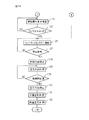
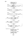
Next, the heat and hydrogen generation control routine shown in FIGS. 12 to 14 will be described. This heat and hydrogen generation control routine is performed when the starter switch 43 of the engine shown in FIG. 1 is turned on, or during the operation of the engine, the temperature TD of the exhaust treatment catalyst 13 is lower than a predetermined lower limit temperature. Run when dropped. The starter switch 43 of the engine may be turned on manually by a driver, or may be automatically turned on as in a hybrid vehicle that uses an engine and an electric motor as drive sources.

熱、水素生成制御ルーチンが実行されると、まず初めに、図12のステップ100において、温度センサ72の出力信号に基づいて、改質用触媒54の下流側端面の温度TCが700℃を越えているか否か、即ち、改質用触媒54による改質作用が可能であるか否かが判別される。改質用触媒4の下流側端面の温度TCが700℃を越えていないと判別されたときには、ステップ101に進み、温度センサ71の出力信号に基づいて、改質用触媒54の上流側端面の温度TCDが、改質用触媒54の上流側端面上において酸化反応を行いうる温度、例えば、300℃以上であるか否かが判別される。改質用触媒54の上流側端面の温度TCDが、300℃以下の場合には、ステップ102に進んで、グロープラグ68がオンとされる。次いで、ステップ103では、グロープラグ68がオンとされてから一定時間を経過したが否かが判別され、一定時間を経過したときにはステップ104に進む。   When the heat and hydrogen generation control routine is executed, first, in step 100 of FIG. 12, the temperature TC of the downstream end face of the reforming catalyst 54 exceeds 700 ° C. based on the output signal of the temperature sensor 72. Whether or not the reforming action by the reforming catalyst 54 is possible. When it is determined that the temperature TC of the downstream end face of the reforming catalyst 4 does not exceed 700 ° C., the routine proceeds to step 101, where the upstream end face of the reforming catalyst 54 is detected based on the output signal of the temperature sensor 71. It is determined whether or not the temperature TCD is a temperature at which an oxidation reaction can be performed on the upstream end face of the reforming catalyst 54, for example, 300 ° C. or higher. When the temperature TCD of the upstream end face of the reforming catalyst 54 is 300 ° C. or lower, the routine proceeds to step 102 where the glow plug 68 is turned on. Next, at step 103, it is determined whether or not a certain time has elapsed since the glow plug 68 was turned on. When the certain time has elapsed, the routine proceeds to step 104.

ステップ104では、空気ポンプ64が作動せしめられ、高温空気流通路62を介して
空気がバーナー燃焼室53に供給される。なお、熱、水素生成装置50の作動が停止されるときに、高温空気弁65が開弁されると共に低温空気弁66が閉弁されており、従って、熱、水素生成装置50が作動せしめられたときには、高温空気流通路62を介して空気がバーナー燃焼室53に供給される。次いで、ステップ105では、グロープラグ68の抵抗値から、グロープラグ68の温度TGが算出される。次いで、ステップ106では、グロープラグ68の温度TGが700℃を越えたか否かが判別される。グロープラグ68の温度TGが700℃を越えていないと判別されたときにはステップ104に戻る。これに対し、グロープラグ68の温度TGが700℃を越えたと判別されたときには、着火可能であると判断され、ステップ107に進む。
In step 104, the air pump 64 is activated and air is supplied to the burner combustion chamber 53 via the high temperature air flow passage 62. When the operation of the heat and hydrogen generation device 50 is stopped, the high temperature air valve 65 is opened and the low temperature air valve 66 is closed, so that the heat and hydrogen generation device 50 is operated. The air is supplied to the burner combustion chamber 53 via the high-temperature air flow passage 62. Next, at step 105, the temperature TG of the glow plug 68 is calculated from the resistance value of the glow plug 68. Next, at step 106, it is judged if the temperature TG of the glow plug 68 has exceeded 700 ° C. When it is determined that the temperature TG of the glow plug 68 does not exceed 700 ° C., the process returns to step 104. On the other hand, when it is determined that the temperature TG of the glow plug 68 has exceeded 700 ° C., it is determined that ignition is possible, and the routine proceeds to step 107.

ステップ107では、バーナー57からバーナー燃焼室53に燃料が噴射され、次いで、ステップ108では、温度センサ71の出力信号に基づいて、改質用触媒54の上流側端面の温度TCDが検出される。次いで、ステップ109では、温度センサ71の出力信号から、燃料が着火したか否かが判別される。燃料が着火すると、改質用触媒54の上流側端面の温度TCDが瞬時に上昇し、従って、温度センサ71の出力信号から、燃料が着火したか否かを判別できることになる。ステップ109において、燃料が着火していないと判別されたときには、ステップ107に戻り、ステップ109において、燃料が着火したと判別されたときには、ステップ110に進んで、グロープラグ68がオフとされる。次いで、図13のステップ111に進む。なお、燃料が着火されると、改質用触媒54の上流側端面の温度TCDは、ただちに、改質用触媒54の上流側端面上において酸化反応を行いうる温度、例えば、300℃以上となる。一方、ステップ101において、改質用触媒54の上流側端面の温度TCDが300℃以上であると判別されたときにも、ステップ111に進む。   In step 107, fuel is injected from the burner 57 into the burner combustion chamber 53. Next, in step 108, the temperature TCD of the upstream end face of the reforming catalyst 54 is detected based on the output signal of the temperature sensor 71. Next, at step 109, it is determined from the output signal of the temperature sensor 71 whether or not the fuel has ignited. When the fuel is ignited, the temperature TCD of the upstream end face of the reforming catalyst 54 is instantaneously increased. Therefore, it can be determined from the output signal of the temperature sensor 71 whether or not the fuel has ignited. When it is determined at step 109 that the fuel is not ignited, the routine returns to step 107. When it is determined at step 109 that the fuel has been ignited, the routine proceeds to step 110, where the glow plug 68 is turned off. Next, the process proceeds to step 111 in FIG. When the fuel is ignited, the temperature TCD at the upstream end face of the reforming catalyst 54 immediately becomes a temperature at which an oxidation reaction can be performed on the upstream end face of the reforming catalyst 54, for example, 300 ° C. or more. . On the other hand, when it is determined in step 101 that the temperature TCD of the upstream end face of the reforming catalyst 54 is 300 ° C. or higher, the process proceeds to step 111.

ステップ111およびステップ112では、1次暖機運転が行われる。即ち、O/Cモル比が3.0となるように、ステップ111では空気ポンプ65の吐出量が制御され、ステップ112ではバーナー57からの供給燃料量が制御される。なお、本発明の実施例では、この1次暖機運転が行われているときには、図9および図11に示されるように、供給空気量および供給燃料量が段階的に増大される。次いで、ステップ113では、温度センサ72の出力信号に基づいて、改質用触媒54の下流側端面の温度TCが700℃を越えたか否かが判別される。改質用触媒4の下流側端面の温度TCが700℃を越えていないと判別されたときには、ステップ111に戻り、1次暖機運転、即ち、熱、水素生成装置50の暖機運転が継続して行われる。これに対し、改質用触媒54の下流側端面の温度TCが700℃を越えたと判別されたときにはステップ114に進む。なお、ステップ100において、改質用触媒4の下流側端面の温度TCが700℃を越えていると判別されたときにも、ステップ114に進む。 In step 111 and step 112, the primary warm-up operation is performed. That is, the discharge amount of the air pump 65 is controlled in step 111 and the amount of fuel supplied from the burner 57 is controlled in step 112 so that the O 2 / C molar ratio is 3.0. In the embodiment of the present invention, when the primary warm-up operation is performed, the supply air amount and the supply fuel amount are increased stepwise as shown in FIGS. 9 and 11. Next, at step 113, based on the output signal of the temperature sensor 72, it is determined whether or not the temperature TC at the downstream end face of the reforming catalyst 54 has exceeded 700 ° C. When it is determined that the temperature TC at the downstream end face of the reforming catalyst 4 does not exceed 700 ° C., the process returns to step 111 and the primary warm-up operation, that is, the heat and hydrogen warm-up operation of the hydrogen generator 50 continues. Done. On the other hand, when it is determined that the temperature TC of the downstream end face of the reforming catalyst 54 has exceeded 700 ° C., the routine proceeds to step 114. If it is determined in step 100 that the temperature TC of the downstream end face of the reforming catalyst 4 exceeds 700 ° C., the process also proceeds to step 114.

ステップ114では、低温空気弁66が開弁され、ステップ115では、高温空気弁65が閉弁される。従って、このときには、空気は低温空気流通路63を介してバーナー燃焼室53に供給される。次いで、ステップ116では、排気処理触媒13の温度TDを目標暖機温度まで上昇させるのに必要な熱、水素生成装置50の出力熱量(kW)の要求値が算出される。次いで、ステップ117では、この出力熱量(kW)の要求出力熱量を発生させるのに必要な目標供給燃料量QFが算出される。次いで、ステップ118では、排気処理触媒13の熱劣化対応処理が行われる。この熱劣化対応処理が図15に示されている。なお、この熱劣化対応処理については、後で説明する。   In step 114, the low temperature air valve 66 is opened, and in step 115, the high temperature air valve 65 is closed. Accordingly, at this time, air is supplied to the burner combustion chamber 53 via the low-temperature air flow passage 63. Next, at step 116, the required value of the heat required to raise the temperature TD of the exhaust treatment catalyst 13 to the target warm-up temperature and the output heat quantity (kW) of the hydrogen generator 50 is calculated. Next, at step 117, a target supply fuel amount QF necessary to generate the required output heat amount of this output heat amount (kW) is calculated. Next, in step 118, the heat treatment for the exhaust treatment catalyst 13 is performed. This heat deterioration handling process is shown in FIG. This thermal deterioration handling process will be described later.

次いで、ステップ119では、排気処理触媒13の温度TDが活性化温度DTよりも高いか否かが判別される。ステップ119において、排気処理触媒13の温度TDが活性化温度DTよりも高いと判別されたときには、ステップ120に進んで、図9に示されるように、2次暖機運転が開始される。即ち、ステップ120では、バーナー57からの供給燃料量をそのまま維持した状態で、O/Cモル比が0.56となるように空気ポンプ64の吐出量が減少せしめられる。このとき、部分酸化改質反応が開始され、熱、水素生成装置50において、熱および水素が生成される。 Next, at step 119, whether high is determined than the temperature TD activation temperature DT 0 of the exhaust treatment catalyst 13. When it is determined at step 119 that the temperature TD of the exhaust treatment catalyst 13 is higher than the activation temperature DT 0 , the routine proceeds to step 120, where the secondary warm-up operation is started as shown in FIG. That is, in step 120, the discharge amount of the air pump 64 is decreased so that the O 2 / C molar ratio becomes 0.56 while maintaining the amount of fuel supplied from the burner 57 as it is. At this time, the partial oxidation reforming reaction is started, and heat and hydrogen are generated in the heat and hydrogen generator 50.

ステップ120において、部分酸化改質反応が開始されると、ステップ121に進んで、改質用触媒54の下流側端面の温度TCが、温度センサ73により検出された空気温TAと805℃との和(TA+805℃)に到達したか否かが判別される。前述したように、この温度(TA+805℃)は、空気温がTA℃のときに、O/Cモル比=0.5でもって部分酸化改質反応が行われたときの反応平衡温度TBを示している。従って、ステップ121では、改質用触媒54の下流側端面の温度TCが、反応平衡温度(TA+805℃)に到達したか否かを判別していることになる。 In step 120, when the partial oxidation reforming reaction is started, the process proceeds to step 121, where the temperature TC of the downstream end face of the reforming catalyst 54 is equal to the air temperature TA detected by the temperature sensor 73 and 805 ° C. It is determined whether or not the sum (TA + 805 ° C.) has been reached. As described above, this temperature (TA + 805 ° C.) is the reaction equilibrium temperature TB when the partial oxidation reforming reaction is performed with an O 2 / C molar ratio = 0.5 when the air temperature is TA ° C. Show. Therefore, in step 121, it is determined whether or not the temperature TC of the downstream end face of the reforming catalyst 54 has reached the reaction equilibrium temperature (TA + 805 ° C.).

改質用触媒54の下流側端面の温度TCが、反応平衡温度(TA+805℃)に到達していないと判別されたときには、ステップ120に戻り、O/Cモル比が0.56となるように空気ポンプ64の吐出量が制御され続ける。これに対し、ステップ121において、改質用触媒54の下流側端面の温度TCが、反応平衡温度(TA+805℃)に到達したと判別されたときには、ステップ122に進み、空気ポンプ15の吐出量を一定に維持した状態で、燃料噴射量が、算出された供給燃料量QFまで徐々に増大される。その結果、O/Cモル比が徐々に減少する。次いで、ステップ123では、O/Cモル比が0.5になったか否かが判別される。O/Cモル比が0.5になっていないと判別されたときには、ステップ122に戻る。これに対し、ステップ123において、O/Cモル比が0.5になったと判別されたときには、2次暖機運転は完了したと判断される。2次暖機運転が完了したと判断されたときには、ステップ126に進んで、通常運転が行われる。ステップ126では、O/Cモル比が0.5となるように空気ポンプ64の吐出量が制御される。 When it is determined that the temperature TC of the downstream end face of the reforming catalyst 54 has not reached the reaction equilibrium temperature (TA + 805 ° C.), the process returns to step 120 so that the O 2 / C molar ratio becomes 0.56. In addition, the discharge amount of the air pump 64 continues to be controlled. On the other hand, when it is determined in step 121 that the temperature TC of the downstream end face of the reforming catalyst 54 has reached the reaction equilibrium temperature (TA + 805 ° C.), the routine proceeds to step 122 where the discharge amount of the air pump 15 is reduced. The fuel injection amount is gradually increased to the calculated supply fuel amount QF while maintaining a constant value. As a result, the O 2 / C molar ratio gradually decreases. Next, at step 123, it is judged if the O 2 / C molar ratio has become 0.5. When it is determined that the O 2 / C molar ratio is not 0.5, the process returns to step 122. On the other hand, when it is determined in step 123 that the O 2 / C molar ratio has become 0.5, it is determined that the secondary warm-up operation has been completed. When it is determined that the secondary warm-up operation has been completed, the routine proceeds to step 126 where normal operation is performed. In step 126, the discharge amount of the air pump 64 is controlled so that the O 2 / C molar ratio becomes 0.5.

一方、ステップ119において、排気処理触媒13の温度TDが活性化温度DT未満であると判別されたときには、ステップ124に進んで、図11に示されるように、運転モードが熱生成モードとされる。即ち、ステップ124では、算出された供給燃料量でもってバーナー57から燃料が噴射され、O2/Cモル比が2.6となるように空気ポンプ64の吐出量が制御される。このとき、リーン空燃比のもとでの完全酸化反応が続行され、熱のみが排気処理触媒13に供給される。次いで、ステップ125では、排気処理触媒13の温度TDが活性化温度DTに到達したか否かが判別される。排気処理触媒13の温度TDが活性化温度DTに到達していないときには、ステップ124に戻る。 On the other hand, when it is determined at step 119 that the temperature TD of the exhaust treatment catalyst 13 is lower than the activation temperature DT 0 , the routine proceeds to step 124 where the operation mode is set to the heat generation mode as shown in FIG. The That is, in step 124, fuel is injected from the burner 57 with the calculated amount of supplied fuel, and the discharge amount of the air pump 64 is controlled so that the O2 / C molar ratio is 2.6. At this time, the complete oxidation reaction under a lean air-fuel ratio is continued, and only heat is supplied to the exhaust treatment catalyst 13. Then, in step 125, the temperature TD of the exhaust treatment catalyst 13 whether the host vehicle has reached the activation temperature DT 0 is determined. When the temperature TD of the exhaust treatment catalyst 13 has not reached the activation temperature DT 0 , the process returns to step 124.

これに対し、ステップ125において、排気処理触媒13の温度TDが活性化温度DTに到達したと判別されたときにはステップ126に進んで、通常運転が行われる。このとき、バーナー57からの供給燃料量をそのまま維持した状態で、O/Cモル比が0.5となるように空気ポンプ64の吐出量が減少せしめられる。このとき、部分酸化改質反応が開始され、熱、水素生成装置50において熱および水素が生成される。 In contrast, in step 125, the temperature TD of the exhaust treatment catalyst 13 proceeds to step 126 when it is judged to have reached the activation temperature DT 0, normal operation is performed. At this time, the discharge amount of the air pump 64 is reduced so that the O 2 / C molar ratio becomes 0.5 while the amount of fuel supplied from the burner 57 is maintained as it is. At this time, the partial oxidation reforming reaction is started, and heat and hydrogen are generated in the heat and hydrogen generator 50.

ステップ126において、通常運転が開始されると、ステップ127に進んで、熱、水素生成装置50の運転を停止すべきであるか否かが判別される。この場合、本発明の実施例では、通常運転が一定期間続行されたとき、又は、排気処理触媒13の温度TDが目標暖機温度に達したとき、又は、その他の理由により熱、水素生成装置50の運転を停止すべき指令が発せられたときに、熱、水素生成装置50の運転を停止すべきであると判別される。ステップ127において、熱、水素生成装置50の運転を停止すべきでないと判別されたときにはステップ126に戻って通常運転が続行される。   In step 126, when normal operation is started, the routine proceeds to step 127, where it is determined whether or not the operation of the heat and hydrogen generator 50 should be stopped. In this case, in the embodiment of the present invention, when the normal operation is continued for a certain period, or when the temperature TD of the exhaust treatment catalyst 13 reaches the target warm-up temperature, or for other reasons, the heat and hydrogen generator When a command to stop the operation of 50 is issued, it is determined that the operation of the heat and hydrogen generator 50 should be stopped. In step 127, when it is determined that the operation of the heat and hydrogen generator 50 should not be stopped, the routine returns to step 126 and the normal operation is continued.

ステップ127において、熱、水素生成装置50の運転を停止すべきであると判別されたときには、ステップ128に進んで、バーナー57からの燃料噴射が停止される。次いで、ステップ129では、残存する燃料を燃焼除去するために、空気ポンプ64から空気が供給され続ける。次いで、ステップ130では、一定時間経過したか否かが判別される。一定時間経過していないと判別されたときには、ステップ129に戻る。これに対し、ステップ130において、一定時間経過したと判別されたときには、ステップ131に進んで、空気ポンプ65の作動が停止され、バーナー燃焼室53内への空気の供給が停止される。次いで、ステップ132では、低温空気弁66が閉弁され、ステップ133では、高温空気弁65が開弁される。次いで、熱、水素生成装置50の作動が停止せしめられている間、低温空気弁66が閉弁され続け、高温空気弁65が開弁され続ける。   When it is determined in step 127 that the operation of the heat and hydrogen generator 50 should be stopped, the routine proceeds to step 128 where fuel injection from the burner 57 is stopped. Next, in step 129, air is continuously supplied from the air pump 64 in order to burn and remove the remaining fuel. Next, at step 130, it is determined whether or not a certain time has elapsed. When it is determined that the predetermined time has not elapsed, the process returns to step 129. On the other hand, when it is determined in step 130 that a certain time has elapsed, the routine proceeds to step 131 where the operation of the air pump 65 is stopped and the supply of air into the burner combustion chamber 53 is stopped. Next, in step 132, the low temperature air valve 66 is closed, and in step 133, the high temperature air valve 65 is opened. Next, while the operation of the heat and hydrogen generator 50 is stopped, the low temperature air valve 66 is kept closed and the high temperature air valve 65 is kept opened.

次に、図16を参照しつつ触媒温度の上昇規制制御ルーチンについて説明する。このルーチンは一定時間毎の割り込みによって実行される。
図16を参照すると、まず初めに、ステップ200において、温度センサ72により検出されている改質用触媒54の下流側端面の温度TCが読み込まれる。次いで、ステップ201では、改質用触媒54の下流側端面の温度TCが許容触媒温度TXを越えたか否かが判別される。改質用触媒54の下流側端面の温度TCが許容触媒温度TXを越えていないと判別されたときには、処理サイクルを完了する。
Next, the catalyst temperature increase restriction control routine will be described with reference to FIG. This routine is executed by interruption every predetermined time.
Referring to FIG. 16, first, in step 200, the temperature TC of the downstream end face of the reforming catalyst 54 detected by the temperature sensor 72 is read. Next, at step 201, it is judged if the temperature TC of the downstream end face of the reforming catalyst 54 has exceeded the allowable catalyst temperature TX. When it is determined that the temperature TC at the downstream end face of the reforming catalyst 54 does not exceed the allowable catalyst temperature TX, the processing cycle is completed.

これに対し、ステップ201において、改質用触媒54の下流側端面の温度TCが許容触媒温度TXを越えたと判別されたときには、ステップ202に進んで、低温空気弁66が開弁され、次いで、ステップ203において、高温空気弁65が閉弁される。次いで、処理サイクルを完了する。即ち、熱、水素生成装置50の運転中において、改質用触媒54の下流側端面の温度TCが許容触媒温度TXを越えたときには、バーナー燃焼室53内に空気を送り込む空気流通経路が、高温の空気を送り込む高温空気流通経路から、低温の空気を送り込む低温空気流通経路に切り替えられ、バーナー燃焼室53内に供給されるバーナー燃焼用空気の温度が低下せしめられる。   On the other hand, when it is determined at step 201 that the temperature TC of the downstream end face of the reforming catalyst 54 has exceeded the allowable catalyst temperature TX, the routine proceeds to step 202 where the low-temperature air valve 66 is opened, and then In step 203, the hot air valve 65 is closed. The processing cycle is then completed. That is, when the temperature TC of the downstream end face of the reforming catalyst 54 exceeds the allowable catalyst temperature TX during the operation of the heat and hydrogen generator 50, the air flow path for sending air into the burner combustion chamber 53 has a high temperature. Is switched from a high-temperature air flow path for feeding the air to a low-temperature air flow path for sending low-temperature air, and the temperature of the burner combustion air supplied into the burner combustion chamber 53 is lowered.

さて、本発明の実施例では、排気処理触媒13はNO吸蔵還元触媒からなり、この場合、排気処理触媒13、即ち、NO吸蔵還元触媒の活性化温度TDは110℃程度である。一方、排気処理触媒13、即ち、NO吸蔵還元触媒の温度が200℃程度になると、NO吸蔵還元触媒13によるNO浄化率はかなり高くなり、NO吸蔵還元触媒の温度が200℃以上になってもNO浄化率はそれ以上増大しない。従って、本発明の実施例では、排気処理触媒13、即ち、NO吸蔵還元触媒の目標暖機温度は、前述したように、200℃とされており、排気処理触媒13の暖機時には、排気処理触媒13の温度TDがこの目標暖機温度まで急速に増大するように、排気処理触媒13に水素が供給される。この場合、排気処理触媒13の温度上昇量は、水素の供給量によって定まり、水素の供給量が多いほど排気処理触媒13の温度上昇量は増大する。 In the embodiment of the present invention, the exhaust treatment catalyst 13 is composed of a NO X storage reduction catalyst. In this case, the activation temperature TD 0 of the exhaust treatment catalyst 13, that is, the NO X storage reduction catalyst is about 110 ° C. On the other hand, the exhaust treatment catalyst 13, i.e., when the temperature of the NO X occluding and reducing catalyst is about 200 ° C., NO X purification rate by the NO X occluding and reducing catalyst 13 is much higher, the temperature of the NO X occluding and reducing catalyst is 200 ° C. or higher does not increase nO X purification rate is higher even at. Thus, in the embodiment of the present invention, the exhaust treatment catalyst 13, i.e., the target warm-up temperature of the NO X occluding and reducing catalyst, as described above, it is a 200 ° C., at the time of warm-up of the exhaust treatment catalyst 13, the exhaust Hydrogen is supplied to the exhaust treatment catalyst 13 so that the temperature TD of the treatment catalyst 13 rapidly increases to the target warm-up temperature. In this case, the temperature increase amount of the exhaust treatment catalyst 13 is determined by the hydrogen supply amount, and the temperature increase amount of the exhaust treatment catalyst 13 increases as the hydrogen supply amount increases.

次に、このことについて、図17Aを参照しつつ説明する。図17Aは、排気ガスによる排気処理触媒13の温度上昇は考慮に入れず、熱、水素生成装置50から排気処理触媒13に供給された熱および水素のみによる排気処理触媒13の温度上昇量ΔTDを示している。図17Aに示されるように、排気処理触媒13の温度上昇量ΔTDは、排気ガス流量Ga(g/s)と、熱、水素生成装置50において部分酸化還元反応が行われているときの、熱、水素生成装置50への供給燃料量QF(g/s)との関数となる。なお、図17Aに示される排気処理触媒13の温度上昇量ΔTDは、排気処理触媒13が被毒しておらずかつ熱劣化していないときの温度上昇量を示している。   Next, this will be described with reference to FIG. 17A. FIG. 17A does not take into account the temperature increase of the exhaust treatment catalyst 13 due to the exhaust gas, and the temperature rise amount ΔTD of the exhaust treatment catalyst 13 due only to heat, heat supplied from the hydrogen generator 50 to the exhaust treatment catalyst 13 and hydrogen alone. Show. As shown in FIG. 17A, the amount of temperature increase ΔTD of the exhaust treatment catalyst 13 is the exhaust gas flow rate Ga (g / s), heat, and heat when a partial oxidation-reduction reaction is performed in the hydrogen generator 50. This is a function of the amount of fuel QF (g / s) supplied to the hydrogen generator 50. The temperature increase amount ΔTD of the exhaust treatment catalyst 13 shown in FIG. 17A indicates the temperature increase amount when the exhaust treatment catalyst 13 is not poisoned and is not thermally deteriorated.

図9および図11を参照しつつ説明したように、排気処理触媒13の温度TDが活性化温度TDを越えたときには、排気処理触媒13の温度TDを目標暖機温度まで上昇させるのに必要な熱、水素生成装置50の出力熱量(kW)の要求値が算出され、この出力熱量(kW)の要求出力熱量を発生させるのに必要な目標供給燃料量が算出される。図17Aに示される熱、水素生成装置50への供給燃料量QFは、この目標供給燃料量を示している。即ち、本発明の実施例では、排気処理触媒13の要求温度上昇量、即ち、活性化温度TDと目標暖機温度との温度差と、排気ガス流量Gaから、図17Aに基づいて、熱、水素生成装置50への供給燃料量QFが算出される。この場合、この供給燃料量QFが熱、水素生成装置50に供給されると、熱、水素生成装置50から供給される熱および水素によって、排気処理触媒13の温度TDは、通常、急速に目標暖機温度まで上昇する。なお、図17Bは、このときの排気処理触媒13における水素濃度を示している。 As described with reference to FIGS. 9 and 11, when the temperature TD of the exhaust treatment catalyst 13 exceeds the activation temperature TD 0 , it is necessary to raise the temperature TD of the exhaust treatment catalyst 13 to the target warm-up temperature. The required value of the required heat and the output heat quantity (kW) of the hydrogen generator 50 is calculated, and the target fuel supply amount required to generate the required output heat quantity of the output heat quantity (kW) is calculated. The heat and fuel supply amount QF to the hydrogen generator 50 shown in FIG. 17A indicate this target fuel supply amount. That is, in the embodiment of the present invention, the required temperature increase of the exhaust treatment catalyst 13, i.e., the temperature difference between the activation temperature TD 0 and the target warm-up temperature, the exhaust gas flow rate Ga, based on FIG. 17A, the heat Then, the amount of fuel QF supplied to the hydrogen generator 50 is calculated. In this case, when the supplied fuel amount QF is supplied to heat, the hydrogen generator 50, the temperature TD of the exhaust treatment catalyst 13 is usually rapidly increased by the heat, heat supplied from the hydrogen generator 50, and hydrogen. Increases to warm-up temperature. FIG. 17B shows the hydrogen concentration in the exhaust treatment catalyst 13 at this time.

ところで、排気処理触媒13に担持された貴金属触媒の表面が、炭化水素、即ち、HCによって覆われると貴金属触媒の活性が低下し、排気処理触媒13がHC被毒を生ずる。また、排気処理触媒13に担持された貴金属触媒の表面が、酸素によって覆われると貴金属触媒の活性が低下し、排気処理触媒13が酸素被毒を生ずる。また、排気処理触媒13の表面にSOが付着すると、或いは、排気処理触媒13内にSOが吸蔵されると貴金属触媒の活性が低下し、排気処理触媒13が硫黄被毒を生ずる。このように排気処理触媒13が被毒すると、図17Aに基づいて算出された供給燃料量QFを熱、水素生成装置50に供給しても、排気処理触媒13の温度TDは、目標暖機温度まで上昇しなくなる。また、排気処理触媒13が熱劣化したときも、同様に、図17Aに基づいて算出された供給燃料量QFを熱、水素生成装置50に供給しても、排気処理触媒13の温度TDは、目標暖機温度まで上昇しなくなる。 By the way, when the surface of the noble metal catalyst supported on the exhaust treatment catalyst 13 is covered with hydrocarbons, that is, HC, the activity of the noble metal catalyst is reduced, and the exhaust treatment catalyst 13 is poisoned by HC. Further, when the surface of the noble metal catalyst supported on the exhaust treatment catalyst 13 is covered with oxygen, the activity of the noble metal catalyst is reduced, and the exhaust treatment catalyst 13 is poisoned by oxygen. Further, if SO X adheres to the surface of the exhaust treatment catalyst 13 or if SO X is occluded in the exhaust treatment catalyst 13, the activity of the noble metal catalyst is reduced, and the exhaust treatment catalyst 13 is poisoned by sulfur. When the exhaust treatment catalyst 13 is poisoned in this way, even if the supply fuel amount QF calculated based on FIG. 17A is supplied to the heat and hydrogen generation device 50, the temperature TD of the exhaust treatment catalyst 13 is the target warm-up temperature. No longer rises. Similarly, even when the exhaust treatment catalyst 13 is thermally deteriorated, even if the supplied fuel amount QF calculated based on FIG. 17A is supplied to the heat and hydrogen generator 50, the temperature TD of the exhaust treatment catalyst 13 is It will not rise to the target warm-up temperature.

このように排気処理触媒13の温度TDが目標暖機温度まで上昇しなくなると、排気浄化率が悪化し、従って、このように排気処理触媒13の温度TDが目標暖機温度まで上昇しなくなった場合には、排気処理触媒13の温度TDを目標暖機温度まで上昇させることが必要となる。この場合、排気処理触媒13が被毒したときには、排気処理触媒13の被毒を回復すれば、熱、水素生成装置50から供給される熱および水素によって、排気処理触媒13の温度TDを目標暖機温度まで上昇させることができる。従って、本発明の実施例では、排気処理触媒13が被毒したときには、排気処理触媒13の被毒回復を行うようにしている。なお、排気処理触媒13が熱劣化したときには、排気処理触媒13を新品と交換しない限り、排気処理触媒13の熱劣化を回復することはできない。そこで本発明の実施例では、排気処理触媒13が熱劣化したときには、排気処理触媒13の暖機時に、燃料消費量は増大するが、水素生成装置50への供給燃料量QFを増大することによって熱、水素生成装置50から供給される熱量および水素量を増大させ、それによって、排気処理触媒13の温度TDを目標暖機温度まで上昇させるようにしている。   Thus, when the temperature TD of the exhaust treatment catalyst 13 does not rise to the target warm-up temperature, the exhaust purification rate deteriorates, and thus the temperature TD of the exhaust treatment catalyst 13 does not rise to the target warm-up temperature in this way. In this case, it is necessary to raise the temperature TD of the exhaust treatment catalyst 13 to the target warm-up temperature. In this case, when the exhaust treatment catalyst 13 is poisoned, if the poisoning of the exhaust treatment catalyst 13 is recovered, the temperature TD of the exhaust treatment catalyst 13 is set to the target warm temperature by heat, heat supplied from the hydrogen generator 50 and hydrogen. The machine temperature can be raised. Therefore, in the embodiment of the present invention, when the exhaust treatment catalyst 13 is poisoned, the poisoning recovery of the exhaust treatment catalyst 13 is performed. When the exhaust treatment catalyst 13 is thermally deteriorated, the heat deterioration of the exhaust treatment catalyst 13 cannot be recovered unless the exhaust treatment catalyst 13 is replaced with a new one. Therefore, in the embodiment of the present invention, when the exhaust treatment catalyst 13 is thermally deteriorated, the fuel consumption increases when the exhaust treatment catalyst 13 is warmed up, but by increasing the supply fuel amount QF to the hydrogen generator 50. The amount of heat and the amount of heat and the amount of hydrogen supplied from the hydrogen generator 50 are increased, thereby increasing the temperature TD of the exhaust treatment catalyst 13 to the target warm-up temperature.

このように排気処理触媒13の被毒回復を行ったり、或いは、水素生成装置50への供給燃料量QFの増大制御を行うためには、排気処理触媒13が被毒しているか否か、或いは、排気処理触媒13が熱劣化しているか否かを検出する、即ち、排気処理触媒13の状態を検出する必要がある。そこで、次に、図18を参照しつつ、排気処理触媒13の状態を検出方法について説明する。図18の実線は、排気処理触媒13が被毒しておらずかつ熱劣化していない場合で、排気処理触媒13の温度TDが活性化温度TDを越えているときに、排気処理触媒13の温度TDを一定温度だけ、例えば、30℃だけ上昇させるのに必要な供給燃料量QFを熱、水素生成装置50に供給したときの排気処理触媒13の温度上昇量ΔTDを示している。本発明の実施例では、この排気処理触媒13の温度TDを一定温度だけ、例えば、30℃だけ上昇させるのに必要な供給燃料量QFを基準供給燃料量QFと称しており、この場合、この基準供給燃料量QFは、排気ガス流量Gaに基づいて、図17Aに示される一覧表から算出することができる。この基準供給燃料量QFが熱、水素生成装置50に供給されると、図18の実線に示されるように、熱、水素生成装置50から供給される熱および水素によって、排気処理触媒13の温度DTは、一定温度だけ、例えば、30℃だけ急速に上昇し、その後は、一定温度に維持される。 Thus, in order to recover poisoning of the exhaust treatment catalyst 13 or to increase control of the fuel amount QF supplied to the hydrogen generator 50, whether or not the exhaust treatment catalyst 13 is poisoned, or It is necessary to detect whether or not the exhaust treatment catalyst 13 is thermally deteriorated, that is, to detect the state of the exhaust treatment catalyst 13. Next, a method for detecting the state of the exhaust treatment catalyst 13 will be described with reference to FIG. The solid line in FIG. 18 shows the case where the exhaust treatment catalyst 13 is not poisoned and is not thermally deteriorated, and when the temperature TD of the exhaust treatment catalyst 13 exceeds the activation temperature TD 0 , The temperature increase ΔTD of the exhaust treatment catalyst 13 when the supply fuel amount QF necessary to increase the temperature TD by a certain temperature, for example, 30 ° C., is supplied to the heat and hydrogen generator 50 is shown. In the embodiment of the present invention, the supply fuel amount QF required to increase the temperature TD of the exhaust treatment catalyst 13 by a constant temperature, for example, 30 ° C. is referred to as a reference supply fuel amount QF. The reference supply fuel amount QF can be calculated from the list shown in FIG. 17A based on the exhaust gas flow rate Ga. When this reference supply fuel amount QF is supplied to heat and the hydrogen generator 50, the temperature of the exhaust treatment catalyst 13 is generated by heat, heat supplied from the hydrogen generator 50 and hydrogen as shown by the solid line in FIG. DT rises rapidly by a constant temperature, for example, 30 ° C., and thereafter is maintained at a constant temperature.

一方、図18の破線は、排気処理触媒13が被毒しているか、或いは、熱劣化している場合において、排気処理触媒13の温度TDが活性化温度TDを越えているときに、図18の実線で示される場合と同じ基準供給燃料量を熱、水素生成装置50に供給したときの排気処理触媒13の温度上昇量ΔTDを示している。このように排気処理触媒13が被毒しているか、或いは、熱劣化している場合には、図18の実線で示される場合と比べて、排気処理触媒13の温度上昇量ΔTDが低下することがわかる。そこで本発明の実施例では、排気処理触媒13が被毒しておらずかつ熱劣化していないときに排気処理触媒13の温度TDを一定温度だけ、例えば、30℃だけ上昇させるのに必要な基準供給燃料量QFを、排気ガス流量Gaに基づいて、図17Aに示される一覧表から算出し、排気処理触媒13の温度TDが活性化温度TDを越えているときに、算出された基準供給燃料量QFを、熱、水素生成装置50に供給し、そのときの排気処理触媒13の温度上昇量ΔTDを検出して検出した排気処理触媒13の温度上昇量ΔTDから、排気処理触媒13が被毒しているか、或いは、熱劣化しているかを判断するようしている。 On the other hand, the broken line in FIG. 18 indicates when the temperature TD of the exhaust treatment catalyst 13 exceeds the activation temperature TD 0 when the exhaust treatment catalyst 13 is poisoned or thermally deteriorated. 18 shows the temperature increase ΔTD of the exhaust treatment catalyst 13 when the same reference supply fuel amount as shown by the solid line 18 is supplied to the heat and hydrogen generator 50. As described above, when the exhaust treatment catalyst 13 is poisoned or thermally deteriorated, the temperature increase amount ΔTD of the exhaust treatment catalyst 13 is reduced as compared with the case shown by the solid line in FIG. I understand. Therefore, in the embodiment of the present invention, it is necessary to increase the temperature TD of the exhaust treatment catalyst 13 by a certain temperature, for example, 30 ° C. when the exhaust treatment catalyst 13 is not poisoned and is not thermally deteriorated. The reference supply fuel amount QF is calculated from the list shown in FIG. 17A based on the exhaust gas flow rate Ga, and the calculated reference when the temperature TD of the exhaust treatment catalyst 13 exceeds the activation temperature TD 0 is calculated. The supplied fuel amount QF is supplied to the heat and hydrogen generator 50, and the exhaust gas treatment catalyst 13 detects the temperature increase amount ΔTD of the exhaust gas treatment catalyst 13 detected by detecting the temperature rise amount ΔTD of the exhaust gas treatment catalyst 13 at that time. It is judged whether it is poisoned or heat-deteriorated.

図19及び図20は、排気処理触媒13が被毒しているか否か、或いは、排気処理触媒13が熱劣化しているか否かを検出する、即ち、排気処理触媒13の状態を検出するためのルーチンを示している。
図19を参照すると、ステップ300からステップ305では、排気処理触媒13の状態を検出するための条件が成立しているか否かが判別される。即ち、まず初めに、ステップ300では、熱、水素生成装置50の作動が停止しているか否かが判別される。図9或いは図11に示されるように熱、水素生成装置50が作動しているときに、排気処理触媒13の状態の検出を行うと、熱、水素生成装置50の制御が不安定となる。従って、熱、水素生成装置50が作動しているときには排気処理触媒13の状態の検出を行わず、熱、水素生成装置50の作動が停止するまで待つために、熱、水素生成装置50が作動しているときにはステップ300に戻る。一方、熱、水素生成装置50の作動が停止しているときには、ステップ301に進む。
19 and 20 are for detecting whether or not the exhaust treatment catalyst 13 is poisoned, or whether or not the exhaust treatment catalyst 13 is thermally deteriorated, that is, for detecting the state of the exhaust treatment catalyst 13. Shows the routine.
Referring to FIG. 19, in steps 300 to 305, it is determined whether or not a condition for detecting the state of the exhaust treatment catalyst 13 is satisfied. That is, first, in step 300, it is determined whether or not the operation of the heat and hydrogen generator 50 is stopped. As shown in FIG. 9 or FIG. 11, if the state of the exhaust treatment catalyst 13 is detected while the heat and hydrogen generator 50 is operating, the control of the heat and hydrogen generator 50 becomes unstable. Therefore, when the heat and hydrogen generator 50 is operating, the detection of the state of the exhaust treatment catalyst 13 is not performed, and the heat and hydrogen generator 50 is operated to wait until the heat and hydrogen generator 50 are stopped. If so, the process returns to step 300. On the other hand, when the operation of the heat and hydrogen generator 50 is stopped, the routine proceeds to step 301.

ステップ301では、改質用触媒54の下流側端面の温度TCが、O/Cモル比=0.5でもって部分酸化改質反応が行われたときの平衡反応温度TB(=TA+805℃)に対し、予め定められた範囲内、例えば、プラスマイナス30℃の範囲内にあるか否かが判別される。即ち、TA+775℃<TC<TA+835℃であるか否かが判別される。TA+775℃<TC<TA+835℃でないときにはステップ300に戻る。これに対し、TA+775℃<TC<TA+835℃であるときにはステップ302に進む。即ち、排気処理触媒13に水素を供給するためには、改質用触媒54の下流側端面の温度TCが、平衡反応温度TB(=TA+805℃)付近にあることが必要であり、従って、改質用触媒54の下流側端面の温度TCが、平衡反応温度TB(=TA+805℃)付近にないときにはステップ300に戻される。なお、熱、水素生成装置50は断熱構造を有しており、従って、実際には、熱、水素生成装置50の作動が停止されても、長い期間に亘って、改質用触媒54の下流側端面の温度TCは、平衡反応温度TB(=TA+805℃)付近に維持される。 In step 301, the temperature TC of the downstream end face of the reforming catalyst 54 is the equilibrium reaction temperature TB (= TA + 805 ° C.) when the partial oxidation reforming reaction is performed with an O 2 / C molar ratio = 0.5. On the other hand, it is determined whether or not it is within a predetermined range, for example, a range of plus or minus 30 ° C. That is, it is determined whether or not TA + 775 ° C. <TC <TA + 835 ° C. If not TA + 775 ° C. <TC <TA + 835 ° C., the process returns to step 300. On the other hand, when TA + 775 ° C. <TC <TA + 835 ° C., the routine proceeds to step 302. That is, in order to supply hydrogen to the exhaust treatment catalyst 13, the temperature TC of the downstream end face of the reforming catalyst 54 needs to be in the vicinity of the equilibrium reaction temperature TB (= TA + 805 ° C.). When the temperature TC at the downstream end face of the quality catalyst 54 is not near the equilibrium reaction temperature TB (= TA + 805 ° C.), the process returns to step 300. Note that the heat and hydrogen generator 50 has a heat insulating structure. Therefore, actually, even if the operation of the heat and hydrogen generator 50 is stopped, the heat and hydrogen generator 50 is downstream of the reforming catalyst 54 over a long period of time. The temperature TC of the side end face is maintained near the equilibrium reaction temperature TB (= TA + 805 ° C.).

次いで、ステップ302では、排気処理触媒13の温度TDが活性化温度TDよりも高く、かつ目標暖機温度TDから一定温度ΔDを差し引いた温度(TDーΔD)よりも低いか否か、即ち、TD<TD<TDーΔDであるか否かが判別される。このステップ302では、排気処理触媒13の状態を検出するために熱、水素生成装置50から熱および水素を供給し始めるときの排気処理触媒13の温度TDの範囲が定められている。この場合、TD<TDであることが要求されていることについては説明が不要であろう。一方、排気処理触媒13の状態については、排気処理触媒13を暖機する際の排気処理触媒13の状態を検出の対象としているので、熱、水素生成装置50から熱および水素が供給されて排気処理触媒13の温度TDが上昇したときに排気処理触媒13の温度TDが目標暖機温度TD以上にならないことが好ましい。従って、熱および水素の供給により排気処理触媒13の温度TDを一定温度だけ、例えば、30℃だけ上昇させる場合には、水素を供給し始めるときの排気処理触媒13の温度TDは、目標暖機温度TDよりも一定温度ΔDだけ、例えば、30℃だけ低い温度(TDーΔD)が上限となる。なお、本発明の実施例では、前述したように、活性化温度TDは110℃程度であり、目標暖機温度TDは200℃程度である。従って、具体的にいうと、ステップ302では、110℃<TD<170℃であるか否かが判別されていることになる。 Next, at step 302, whether or not the temperature TD of the exhaust treatment catalyst 13 is higher than the activation temperature TD 0 and lower than a temperature obtained by subtracting a constant temperature ΔD from the target warm-up temperature TD 1 (TD 1 −ΔD). That is, it is determined whether or not TD 0 <TD <TD 1 −ΔD. In this step 302, the range of the temperature TD of the exhaust treatment catalyst 13 when the heat and the heat and hydrogen are started to be supplied from the hydrogen generator 50 in order to detect the state of the exhaust treatment catalyst 13 is determined. In this case, it will not be necessary to explain that TD 0 <TD is required. On the other hand, as for the state of the exhaust treatment catalyst 13, since the state of the exhaust treatment catalyst 13 when the exhaust treatment catalyst 13 is warmed up is the object of detection, heat and hydrogen are supplied from the heat, the hydrogen generator 50, and exhaust is performed. It is preferable that the temperature TD of the exhaust treatment catalyst 13 does not become equal to or higher than the target warm-up temperature TD 1 when the temperature TD of the treatment catalyst 13 increases. Accordingly, when the temperature TD of the exhaust treatment catalyst 13 is increased by a constant temperature, for example, 30 ° C. by supplying heat and hydrogen, the temperature TD of the exhaust treatment catalyst 13 when starting to supply hydrogen is set to the target warm-up. The upper limit is a temperature (TD 1 −ΔD) lower than the temperature TD 1 by a constant temperature ΔD, for example, 30 ° C. In the embodiment of the present invention, as described above, the activation temperature TD 0 is about 110 ° C., and the target warm-up temperature TD 1 is about 200 ° C. Therefore, specifically, in step 302, it is determined whether 110 ° C. <TD <170 ° C. or not.

ステップ302において、TD<TD<TDーΔDではないと判別されたときにはステップ300に戻る。これに対し、ステップ302において、TD<TD<TDーΔDであると判別されたときにはステップ303に進む。ステップ303からステップ305では、排気ガス流の変動の少ない機関運転状態であるか否かが判別され、排気ガス流の変動の大きい機関運転状態であると判別されたときにはステップ300に戻り、排気ガス流の変動の少ない機関運転状態であると判別されたときにステップ306に進む。即ち、ステップ303では、機関低負荷定常運転が一定時間以上、継続しているか否かが判別される。機関低負荷定常運転が一定時間以上、継続しているときにはステップ306に進み、機関低負荷定常運転が一定時間以上、継続していないときにはステップ304に進む。ステップ304では、機関のアイドリング運転が一定時間以上、継続しているか否かが判別される。機関のアイドリング運転が一定時間以上、継続しているときにはステップ306に進み、機関のアイドリング運転が一定時間以上、継続していないときにはステップ305に進む。ステップ305では、機関減速運転時において排気ガス流量Ga一定の状態が一定時間以上、継続しているか否かが判別される。機関減速運転時において排気ガス流量Ga一定の状態が一定時間以上、継続しているときにはステップ306に進み、機関減速運転時において排気ガス流量Ga一定の状態が一定時間以上、継続していないときにはステップ300に戻る。 If it is determined in step 302 that TD 0 <TD <TD 1 −ΔD is not satisfied, the process returns to step 300. On the other hand, when it is determined in step 302 that TD 0 <TD <TD 1 −ΔD, the process proceeds to step 303. In step 303 to step 305, it is determined whether or not the engine operating state has a small fluctuation in the exhaust gas flow. When it is determined that the engine operating state has a large fluctuation in the exhaust gas flow, the process returns to step 300 to When it is determined that the engine is operating with little flow fluctuation, the routine proceeds to step 306. That is, in step 303, it is determined whether or not the engine low load steady operation has continued for a certain time or more. When the engine low load steady operation has continued for a certain time or longer, the routine proceeds to step 306, and when the engine low load steady operation has not continued for a certain time or longer, the routine proceeds to step 304. In step 304, it is determined whether or not the idling operation of the engine has continued for a certain time or more. When the engine idling operation has continued for a certain time or longer, the routine proceeds to step 306, and when the engine idling operation has not continued for a certain time or longer, the routine proceeds to step 305. In step 305, it is determined whether or not a constant state of the exhaust gas flow rate Ga has continued for a certain period of time during engine deceleration operation. If the constant exhaust gas flow rate Ga continues for a predetermined time or more during engine deceleration operation, the process proceeds to step 306. If the constant exhaust gas flow rate Ga does not continue for a predetermined time or longer during engine deceleration operation, step 306 is performed. Return to 300.

ステップ306からステップ318では、排気処理触媒13の状態の検出制御が行われる。即ち、ステップ306では、低温空気弁66が開弁され、次いでステップ307では、高温空気弁65が閉弁される。次いで、ステップ308では、吸入空気量検出器8により検出された吸入空気量から排気ガス流量Gaが算出される。次いでステップ309では、算出された排気ガス流量Gaを用いて、図17Aに示される一覧表から、排気処理触媒13の温度TDを一定温度だけ、本発明の実施例では、排気処理触媒13の温度TDを30℃だけ上昇させるのに必要な基準供給燃料量QFが算出される。次いでステップ310では、熱、水素生成装置50が作動せしめられ、ステップ309において算出された基準供給燃料量QFが、熱、水素生成装置50に供給される。次いで、ステップ311では、熱、水素生成装置50に空気が供給され、O/Cモル比=0.5となるように供給空気量が制御される。このとき熱、水素生成装置50内では部分酸化改質反応が行われ、生成された熱および水素が、供給通路51を介して排気処理触媒13に供給される。 From step 306 to step 318, detection control of the state of the exhaust treatment catalyst 13 is performed. That is, in step 306, the low temperature air valve 66 is opened, and then in step 307, the high temperature air valve 65 is closed. Next, at step 308, the exhaust gas flow rate Ga is calculated from the intake air amount detected by the intake air amount detector 8. Next, at step 309, using the calculated exhaust gas flow rate Ga, from the list shown in FIG. 17A, the temperature TD of the exhaust treatment catalyst 13 is set to a fixed temperature. In the embodiment of the present invention, the temperature of the exhaust treatment catalyst 13 is set. A reference supply fuel amount QF required to increase TD by 30 ° C. is calculated. Next, at step 310, the heat and hydrogen generator 50 is activated, and the reference supply fuel amount QF calculated at step 309 is supplied to the heat and hydrogen generator 50. Next, in step 311, air is supplied to the heat and hydrogen generator 50, and the supply air amount is controlled so that the O 2 / C molar ratio = 0.5. At this time, a partial oxidation reforming reaction is performed in the heat and hydrogen generator 50, and the generated heat and hydrogen are supplied to the exhaust treatment catalyst 13 through the supply passage 51.

次いで、ステップ312では、一定時間が経過したか否かが判別される。この一定時間は、水素が供給されたときに、排気処理触媒13の温度TDの上昇作用が終了するまでの時間、例えば、5秒とされる。ステップ312において、一定時間が経過していないと判別されたときにはステップ310に戻り、生成された熱および水素が、供給通路51を介して排気処理触媒13に供給され続ける。一方、ステップ312において、一定時間が経過したと判別されたときにはステップ313に進んで、排気処理触媒13への熱および水素の供給が開始されたときからの排気処理触媒13の温度上昇量ΔTDが、図18に示される予め定められた基準温度上昇量XTDを越えたか否かが判別される。この基準温度上昇量XTDは、排気処理触媒13の温度上昇量ΔTDがこの基準温度上昇量XTDを越えれば、排気処理触媒13が被毒しておらず、熱劣化していないと判断することのできる温度上昇量である。   Next, at step 312, it is determined whether or not a certain time has elapsed. This predetermined time is set to, for example, 5 seconds until the rise of the temperature TD of the exhaust treatment catalyst 13 is finished when hydrogen is supplied. If it is determined in step 312 that the predetermined time has not elapsed, the process returns to step 310, and the generated heat and hydrogen continue to be supplied to the exhaust treatment catalyst 13 via the supply passage 51. On the other hand, when it is determined in step 312 that a certain time has elapsed, the routine proceeds to step 313, where the temperature increase amount ΔTD of the exhaust treatment catalyst 13 from when the supply of heat and hydrogen to the exhaust treatment catalyst 13 is started is determined. Then, it is determined whether or not a predetermined reference temperature increase amount XTD shown in FIG. 18 has been exceeded. This reference temperature increase amount XTD is determined that if the temperature increase amount ΔTD of the exhaust treatment catalyst 13 exceeds the reference temperature increase amount XTD, the exhaust treatment catalyst 13 is not poisoned and is not thermally deteriorated. The amount of temperature increase that can be achieved.

ステップ313において、排気処理触媒13の温度上昇量ΔTDが基準温度上昇量XTDを越えたと判別されたときには、ステップ314に進んで正常フラグがセットされ、次いでステップ315に進む。これに対し、ステップ313において、排気処理触媒13の温度上昇量ΔTDが基準温度上昇量XTDを越えていないと判別されたときには、ステップ315に進む。従って、正常フラグがセットされるのは、排気処理触媒13が被毒しておらず、熱劣化していないときである。ステップ315では熱、水素生成装置50への燃料の供給が停止され、ステップ316では熱、水素生成装置50への空気の供給が停止される。それにより熱、水素生成装置50の作動が停止される。次いで、ステップ317では、低温空気弁66が閉弁され、次いでステップ318では、高温空気弁65が開弁される。   When it is determined in step 313 that the temperature increase amount ΔTD of the exhaust treatment catalyst 13 has exceeded the reference temperature increase amount XTD, the routine proceeds to step 314, where the normal flag is set, and then proceeds to step 315. On the other hand, when it is determined in step 313 that the temperature increase amount ΔTD of the exhaust treatment catalyst 13 does not exceed the reference temperature increase amount XTD, the process proceeds to step 315. Therefore, the normal flag is set when the exhaust treatment catalyst 13 is not poisoned and is not thermally deteriorated. In step 315, supply of heat and fuel to the hydrogen generator 50 is stopped, and in step 316, supply of heat and air to the hydrogen generator 50 is stopped. Thereby, the operation of the heat and hydrogen generator 50 is stopped. Next, at step 317, the low temperature air valve 66 is closed, and then at step 318, the high temperature air valve 65 is opened.

本発明の実施例では、図19および図20に示される排気処理触媒13の触媒状態検出ルーチンを用いて、排気処理触媒13の暖機性能の回復制御が行われる。この排気処理触媒13の暖機性能の回復制御は、排気処理触媒13の暖機性能の回復制御が完了した後、例えば、車両の走行距離が50kmを越える毎に、繰り返し行われる。図22および図23は、排気処理触媒13の暖機性能の回復制御ルーチンを示しており、図21は、この排気処理触媒13の暖機性能の回復制御ルーチンの実行を開始させる触媒暖機性能回復指令を発生するためのルーチンを示している。そこで、まず初めに、図21に示される触媒暖機性能回復指令を発生するためのルーチンから説明を始める。このルーチンは一定時間毎の割込みによって実行される。   In the embodiment of the present invention, recovery control of the warm-up performance of the exhaust treatment catalyst 13 is performed using the catalyst state detection routine of the exhaust treatment catalyst 13 shown in FIGS. 19 and 20. The recovery control of the warm-up performance of the exhaust treatment catalyst 13 is repeatedly performed, for example, every time the travel distance of the vehicle exceeds 50 km after the warm-up performance recovery control of the exhaust treatment catalyst 13 is completed. FIGS. 22 and 23 show a recovery control routine for the warm-up performance of the exhaust treatment catalyst 13, and FIG. 21 shows a catalyst warm-up performance for starting the execution of the recovery control routine for the warm-up performance of the exhaust treatment catalyst 13. Fig. 4 shows a routine for generating a recovery command. Therefore, first, the description starts from the routine for generating the catalyst warm-up performance recovery command shown in FIG. This routine is executed by interruption every predetermined time.

図21を参照すると、まず初めに、ステップ400において、触媒暖機性能回復指令が発生しているか否かが判別される。触媒暖機性能回復指令が発生していないときにはステップ401に進んで、車両の走行距離Sが、排気処理触媒13の暖機性能の回復制御を実行する目標走行距離SOを越えたか否かが判別される。車両の走行距離Sが目標走行距離SOを越えていないときには処理サイクルを終了する。これに対し、ステップ401において車両の走行距離Sが目標走行距離SOを越えたと判別されたときにはステップ402に進んで、触媒暖機性能回復指令が発生せしめられる。触媒暖機性能回復指令が発生せしめられると、図22および図23に示される排気処理触媒13の暖機性能の回復制御ルーチンの実行が開始される。   Referring to FIG. 21, first, at step 400, it is judged if a catalyst warm-up performance recovery command has been issued. When the catalyst warm-up performance recovery command is not generated, the routine proceeds to step 401, where it is determined whether or not the vehicle travel distance S has exceeded the target travel distance SO for executing the warm-up performance recovery control of the exhaust treatment catalyst 13. Is done. When the travel distance S of the vehicle does not exceed the target travel distance SO, the processing cycle ends. On the other hand, when it is determined at step 401 that the vehicle travel distance S has exceeded the target travel distance SO, the routine proceeds to step 402 where a catalyst warm-up performance recovery command is generated. When the catalyst warm-up performance recovery command is generated, the execution of the warm-up performance recovery control routine of the exhaust treatment catalyst 13 shown in FIGS. 22 and 23 is started.

触媒暖機性能回復指令が発生せしめられると、次の処理サイクルでは、ステップ400からステップ403に進み、図22および図23に示される排気処理触媒13の暖機性能の回復制御ルーチンの実行が完了したか否か判別される。排気処理触媒13の暖機性能の回復制御ルーチンの実行が完了したときにはステップ404に進んで触媒暖機性能回復指令が取り下げられる。次いでステップ405では、車両の目標走行距離SOに50kmが加算される。従って、排気処理触媒13の暖機性能の回復制御が完了した後、車両の走行距離が50kmを越えたときに、再び、排気処理触媒13の暖機性能の回復制御が行われる。   When the catalyst warm-up performance recovery command is generated, in the next processing cycle, the process proceeds from step 400 to step 403, and execution of the warm-up performance recovery control routine of the exhaust processing catalyst 13 shown in FIGS. 22 and 23 is completed. It is discriminated whether or not. When the execution of the warm-up performance recovery control routine of the exhaust treatment catalyst 13 is completed, the routine proceeds to step 404 where the catalyst warm-up performance recovery command is withdrawn. Next, at step 405, 50 km is added to the target travel distance SO of the vehicle. Therefore, after the recovery control of the warm-up performance of the exhaust treatment catalyst 13 is completed, the recovery control of the warm-up performance of the exhaust treatment catalyst 13 is performed again when the travel distance of the vehicle exceeds 50 km.

次に、図22および図23に示される排気処理触媒13の暖機性能の回復制御ルーチンについて説明する。図22を参照すると、まず初めに、ステップ500において、図19および図20に示される排気処理触媒13の触媒状態検出ルーチンが実行される。次いで、ステップ501では、正常フラグがセットされているか否かが判別される。前述したように、図19および図20に示される排気処理触媒13の触媒状態検出ルーチンにおいて正常フラグがセットされるのは、排気処理触媒13が被毒しておらず、熱劣化していないときである。ステップ501において、正常フラグがセットされていると判別されたとき、即ち、排気処理触媒13が被毒しておらず、熱劣化していないときには、ステップ511に進んで正常フラグがリセットされ、排気処理触媒13の暖機性能の回復制御が完了せしめられる。   Next, the recovery control routine for the warm-up performance of the exhaust treatment catalyst 13 shown in FIGS. 22 and 23 will be described. Referring to FIG. 22, first, at step 500, a catalyst state detection routine of the exhaust treatment catalyst 13 shown in FIGS. 19 and 20 is executed. Next, at step 501, it is determined whether or not the normal flag is set. As described above, the normal flag is set in the catalyst state detection routine of the exhaust treatment catalyst 13 shown in FIGS. 19 and 20 when the exhaust treatment catalyst 13 is not poisoned and is not thermally deteriorated. It is. When it is determined in step 501 that the normal flag is set, that is, when the exhaust treatment catalyst 13 is not poisoned and is not thermally deteriorated, the routine proceeds to step 511, where the normal flag is reset and the exhaust gas is exhausted. Recovery control of the warm-up performance of the treatment catalyst 13 is completed.

一方、ステップ501において、正常フラグがセットされていないと判別されたとき、即ち、排気処理触媒13が被毒しているか、或いは、熱劣化しているときには、ステップ502に進んで、排気処理触媒13のHC被毒を回復するためのHC被毒回復制御が行われる。このHC被毒回復制御ルーチンが図24および図25に示されている。このHC被毒回復制御ルーチンについては、後で説明する。排気処理触媒13のHC被毒回復制御が完了するとステップ503に進んで、再び、図19および図20に示される排気処理触媒13の触媒状態検出ルーチンが実行される。次いで、ステップ504では、正常フラグがセットされているか否かが判別される。   On the other hand, when it is determined in step 501 that the normal flag is not set, that is, when the exhaust treatment catalyst 13 is poisoned or thermally deteriorated, the routine proceeds to step 502, where the exhaust treatment catalyst HC poisoning recovery control for recovering 13 HC poisoning is performed. This HC poisoning recovery control routine is shown in FIGS. This HC poisoning recovery control routine will be described later. When the HC poisoning recovery control of the exhaust treatment catalyst 13 is completed, the routine proceeds to step 503, where the catalyst state detection routine of the exhaust treatment catalyst 13 shown in FIGS. 19 and 20 is executed again. Next, at step 504, it is judged if the normal flag is set.

前述したように、図19および図20に示される排気処理触媒13の触媒状態検出ルーチンにおいて正常フラグがセットされるのは、排気処理触媒13が被毒しておらず、熱劣化していないときである。従って、ステップ503の排気処理触媒13の触媒状態検出ルーチンにおいて正常フラグがセットされるのは、排気処理触媒13が、酸素被毒や硫黄被毒や熱劣化はしておらず、HC被毒をしており、ステップ502における排気処理触媒13のHC被毒回復制御において、HC被毒が回復されたときである。ステップ504において、正常フラグがセットされていると判別されたとき、即ち、排気処理触媒13が被毒していない正常な状態となり、排気処理触媒13が熱劣化していないときには、ステップ511に進んで正常フラグがリセットされ、排気処理触媒13の暖機性能の回復制御が完了せしめられる。   As described above, the normal flag is set in the catalyst state detection routine of the exhaust treatment catalyst 13 shown in FIGS. 19 and 20 when the exhaust treatment catalyst 13 is not poisoned and is not thermally deteriorated. It is. Therefore, the normal flag is set in the catalyst state detection routine of the exhaust treatment catalyst 13 in step 503 because the exhaust treatment catalyst 13 is not oxygen poisoning, sulfur poisoning, or heat deterioration, and is not HC poisoning. This is when the HC poisoning is recovered in the HC poisoning recovery control of the exhaust treatment catalyst 13 in step 502. When it is determined in step 504 that the normal flag is set, that is, when the exhaust treatment catalyst 13 is in a normal state where it is not poisoned and the exhaust treatment catalyst 13 is not thermally deteriorated, the routine proceeds to step 511. Thus, the normal flag is reset, and the recovery control of the warm-up performance of the exhaust treatment catalyst 13 is completed.

一方、ステップ504において、正常フラグがセットされていないと判別されたとき、即ち、排気処理触媒13が、HC被毒以外の被毒、即ち、酸素被毒又は硫黄被毒しているか、或いは、熱劣化しているときには、ステップ505に進んで、排気処理触媒13の酸素被毒を回復するための酸素被毒回復制御が行われる。この酸素被毒回復制御ルーチンが図26および図27に示されている。この酸素被毒回復制御ルーチンについては、後で説明する。排気処理触媒13の酸素被毒回復制御が完了するとステップ506に進んで、再び、図19および図20に示される排気処理触媒13の触媒状態検出ルーチンが実行される。次いで、ステップ507では、正常フラグがセットされているか否かが判別される。   On the other hand, when it is determined in step 504 that the normal flag is not set, that is, the exhaust treatment catalyst 13 is poisoned other than HC poisoning, that is, oxygen poisoning or sulfur poisoning, or When the heat deterioration has occurred, the routine proceeds to step 505, where oxygen poisoning recovery control for recovering the oxygen poisoning of the exhaust treatment catalyst 13 is performed. This oxygen poisoning recovery control routine is shown in FIGS. This oxygen poisoning recovery control routine will be described later. When the oxygen poisoning recovery control of the exhaust treatment catalyst 13 is completed, the routine proceeds to step 506, and the catalyst state detection routine of the exhaust treatment catalyst 13 shown in FIGS. 19 and 20 is executed again. Next, at step 507, it is judged if the normal flag is set.

前述したように、図19および図20に示される排気処理触媒13の触媒状態検出ルーチンにおいて正常フラグがセットされるのは、排気処理触媒13が被毒しておらず、熱劣化していないときである。従って、ステップ507の排気処理触媒13の触媒状態検出ルーチンにおいて正常フラグがセットされるのは、排気処理触媒13が、硫黄被毒や熱劣化はしておらず、酸素被毒をしており、ステップ505における排気処理触媒13の酸素被毒回復制御において、酸素被毒が回復されたときである。ステップ507において、正常フラグがセットされていると判別されたとき、即ち、排気処理触媒13が被毒していない正常な状態となり、排気処理触媒13が熱劣化していないときには、ステップ511に進んで正常フラグがリセットされ、排気処理触媒13の暖機性能の回復制御が完了せしめられる。   As described above, the normal flag is set in the catalyst state detection routine of the exhaust treatment catalyst 13 shown in FIGS. 19 and 20 when the exhaust treatment catalyst 13 is not poisoned and is not thermally deteriorated. It is. Therefore, the normal flag is set in the catalyst state detection routine of the exhaust treatment catalyst 13 in step 507 because the exhaust treatment catalyst 13 is not sulfur poisoning or heat-degraded and is oxygen poisoned. This is when the oxygen poisoning is recovered in the oxygen poisoning recovery control of the exhaust treatment catalyst 13 in step 505. When it is determined in step 507 that the normal flag is set, that is, when the exhaust treatment catalyst 13 is in a normal state where it is not poisoned and the exhaust treatment catalyst 13 is not thermally deteriorated, the routine proceeds to step 511. Thus, the normal flag is reset, and the recovery control of the warm-up performance of the exhaust treatment catalyst 13 is completed.

一方、ステップ507において、正常フラグがセットされていないと判別されたとき、即ち、排気処理触媒13が硫黄被毒しているか、或いは、熱劣化しているときには、ステップ508に進んで、排気処理触媒13の硫黄被毒を回復するための硫黄被毒回復制御が行われる。この硫黄被毒回復制御ルーチンが図28および図29に示されている。この硫黄被毒回復制御ルーチンについては、後で説明する。排気処理触媒13の硫黄被毒回復制御が完了するとステップ509に進んで、再び、図19および図20に示される排気処理触媒13の触媒状態検出ルーチンが実行される。次いで、ステップ510では、正常フラグがセットされているか否かが判別される。   On the other hand, when it is determined in step 507 that the normal flag is not set, that is, when the exhaust treatment catalyst 13 is sulfur poisoned or thermally deteriorated, the routine proceeds to step 508, where the exhaust treatment is performed. Sulfur poisoning recovery control for recovering the sulfur poisoning of the catalyst 13 is performed. This sulfur poisoning recovery control routine is shown in FIGS. This sulfur poisoning recovery control routine will be described later. When the sulfur poisoning recovery control of the exhaust treatment catalyst 13 is completed, the routine proceeds to step 509, and the catalyst state detection routine of the exhaust treatment catalyst 13 shown in FIGS. 19 and 20 is executed again. Next, at step 510, it is judged if the normal flag is set.

前述したように、図19および図20に示される排気処理触媒13の触媒状態検出ルーチンにおいて正常フラグがセットされるのは、排気処理触媒13が被毒しておらず、熱劣化していないときである。従って、ステップ509の排気処理触媒13の触媒状態検出ルーチンにおいて正常フラグがセットされるのは、排気処理触媒13が、HC被毒や酸素被毒や熱劣化はしておらず、硫黄被毒をしており、ステップ508における排気処理触媒13の硫黄被毒回復制御において、硫黄被毒が回復されたときである。ステップ510において、正常フラグがセットされていると判別されたとき、即ち、排気処理触媒13が被毒していない正常な状態となり、排気処理触媒13が熱劣化していないときには、ステップ511に進んで正常フラグがリセットされ、排気処理触媒13の暖機性能の回復制御が完了せしめられる。   As described above, the normal flag is set in the catalyst state detection routine of the exhaust treatment catalyst 13 shown in FIGS. 19 and 20 when the exhaust treatment catalyst 13 is not poisoned and is not thermally deteriorated. It is. Therefore, the normal flag is set in the catalyst state detection routine of the exhaust treatment catalyst 13 in step 509 because the exhaust treatment catalyst 13 is not HC poisoned, oxygen poisoned or thermally deteriorated, and sulfur poisoned. In the sulfur poisoning recovery control of the exhaust treatment catalyst 13 in step 508, the sulfur poisoning is recovered. When it is determined at step 510 that the normal flag is set, that is, when the exhaust treatment catalyst 13 is in a normal state where it is not poisoned and the exhaust treatment catalyst 13 is not thermally deteriorated, the routine proceeds to step 511. Thus, the normal flag is reset, and the recovery control of the warm-up performance of the exhaust treatment catalyst 13 is completed.

一方、排気処理触媒13がHC被毒も酸素被毒も硫黄被毒もしていないときには、ステップ510において、正常フラグがセットされていないと判別される。即ち、ステップ510において、正常フラグがセットされていないと判別されるのは、排気処理触媒13が熱劣化しているときである。このときにはステップ512に進んで、排気処理触媒13の暖機を促進させるための熱劣化対応制御が行われる。この熱劣化対応制御ルーチンが図32から図34に示されている。この熱劣化対応制御ルーチンについては、後で説明する。排気処理触媒13の熱劣化対応制御が完了すると、排気処理触媒13の暖機性能の回復制御が完了せしめられる。   On the other hand, when the exhaust treatment catalyst 13 is not HC poisoned, oxygen poisoned, or sulfur poisoned, it is determined in step 510 that the normal flag is not set. That is, in step 510, it is determined that the normal flag is not set when the exhaust treatment catalyst 13 is thermally deteriorated. At this time, the routine proceeds to step 512, where thermal deterioration countermeasure control for promoting warm-up of the exhaust treatment catalyst 13 is performed. This thermal deterioration countermeasure control routine is shown in FIGS. This thermal deterioration countermeasure control routine will be described later. When the control for thermal degradation of the exhaust treatment catalyst 13 is completed, the recovery control for the warm-up performance of the exhaust treatment catalyst 13 is completed.

このように、本発明の実施例では、機関排気通路内に配置された排気処理触媒13と、排気処理触媒13を暖機するために排気処理触媒13に熱のみ、又は熱および水素を供給可能な熱、水素生成装置50とが設けられている。この熱、水素生成装置50が、燃料および空気の燃焼ガスが送り込まれる改質用触媒54を備えており、熱、水素生成装置50では、改質用触媒54による燃料の改質作用が可能になったときには、部分酸化反応を行わせることにより熱および水素が生成され、燃料をリーン空燃比のもとで燃焼させることにより熱が生成される。排気処理触媒13が被毒しておらずかつ熱劣化していないときに熱、水素生成装置50から供給される熱および水素により排気処理触媒13の温度を予め定められた温度上昇量だけ上昇させるのに必要な熱、水素生成装置50への供給燃料量QFが、基準供給燃料量QFとして排気ガス量Gaの関数の形で予め記憶されており、排気ガス量Gaに応じた基準供給燃料量QFの燃料を熱、水素生成装置50に供給したときに排気処理触媒13の温度TDが、予め定められた温度上昇量XTDまで達しなかったときには、排気処理触媒13の被毒回復処理が行われる。   Thus, in the embodiment of the present invention, only the heat or heat and hydrogen can be supplied to the exhaust treatment catalyst 13 to warm up the exhaust treatment catalyst 13 disposed in the engine exhaust passage. Heat and hydrogen generator 50 are provided. The heat and hydrogen generation device 50 includes a reforming catalyst 54 into which fuel and air combustion gas are sent. The heat and hydrogen generation device 50 enables the reforming catalyst 54 to reform the fuel. When this happens, heat and hydrogen are generated by performing a partial oxidation reaction, and heat is generated by burning the fuel under a lean air-fuel ratio. When the exhaust treatment catalyst 13 is not poisoned and is not thermally deteriorated, the temperature of the exhaust treatment catalyst 13 is increased by a predetermined temperature increase amount by heat, heat supplied from the hydrogen generator 50 and hydrogen. The amount of heat necessary for the fuel generation and the fuel supply amount QF to the hydrogen generator 50 are stored in advance as a reference supply fuel amount QF in the form of a function of the exhaust gas amount Ga, and the reference supply fuel amount corresponding to the exhaust gas amount Ga When the temperature TD of the exhaust treatment catalyst 13 does not reach the predetermined temperature increase amount XTD when the QF fuel is supplied to the heat and hydrogen generator 50, the poisoning recovery process of the exhaust treatment catalyst 13 is performed. .

この場合、本発明の実施例では、改質用触媒54の下流側端面の温度TCが、部分酸化改質反応が行われたときの平衡反応温度TB(=TA+805℃)に対し、予め定められた範囲内にあり、排気処理触媒13の温度TDが活性化温度TD以上であるときに、排気処理触媒13の温度TDが、予め定められた温度上昇量XTDまで達するか否かを判別するために、排気ガス量Gaに応じた基準供給燃料量QFの燃料が熱、水素生成装置50に供給される。 In this case, in the embodiment of the present invention, the temperature TC of the downstream end face of the reforming catalyst 54 is predetermined with respect to the equilibrium reaction temperature TB (= TA + 805 ° C.) when the partial oxidation reforming reaction is performed. When the temperature TD of the exhaust treatment catalyst 13 is equal to or higher than the activation temperature TD 0 , it is determined whether or not the temperature TD of the exhaust treatment catalyst 13 reaches a predetermined temperature increase amount XTD. Therefore, the fuel of the reference supply fuel amount QF corresponding to the exhaust gas amount Ga is supplied to the heat and hydrogen generator 50.

また、本発明の実施例では、改質用触媒54の下流側端面の温度TCが、部分酸化改質反応が行われたときの平衡反応温度TB(=TA+805℃)に対し、予め定められた範囲内にあり、かつ排気処理触媒13の温度TDが活性化温度TD以上であるときに、再度、排気ガス量Gaに応じた基準供給燃料量QFの燃料が熱、水素生成装置50に供給される。 In the embodiment of the present invention, the temperature TC of the downstream end face of the reforming catalyst 54 is predetermined with respect to the equilibrium reaction temperature TB (= TA + 805 ° C.) when the partial oxidation reforming reaction is performed. When the temperature TD of the exhaust treatment catalyst 13 is within the range and the activation temperature TD 0 is equal to or higher than the activation temperature TD 0 , the fuel of the reference supply fuel amount QF corresponding to the exhaust gas amount Ga is supplied again to the heat and hydrogen generator 50. Is done.

次に、図24および図25を参照しつつ、図22のステップ502において実行されるHC被毒回復制御について説明する。
図24を参照すると、まず初めに、ステップ600において、熱、水素生成装置50の作動が停止しているか否かが判別される。熱、水素生成装置50が作動しているときにはステップ600に戻り、熱、水素生成装置50の作動が停止しているときには、ステップ601に進む。ステップ601では、改質用触媒54の下流側端面の温度TCが、O/Cモル比=0.5でもって部分酸化改質反応が行われたときの平衡反応温度TB(=TA+805℃)に対し、予め定められた範囲内、例えば、プラスマイナス30℃の範囲内にあるか否かが判別される。即ち、TA+775℃<TC<TA+835℃であるか否かが判別される。TA+775℃<TC<TA+835℃でないときにはステップ600に戻る。これに対し、TA+775℃<TC<TA+835℃であるときにはステップ602に進む。
Next, the HC poisoning recovery control executed in step 502 of FIG. 22 will be described with reference to FIGS.
Referring to FIG. 24, first, at step 600, it is determined whether or not the operation of the heat and hydrogen generator 50 is stopped. When the heat and hydrogen generator 50 is operating, the process returns to step 600, and when the operation of the heat and hydrogen generator 50 is stopped, the process proceeds to step 601. In step 601, the temperature TC of the downstream end face of the reforming catalyst 54 is an equilibrium reaction temperature TB (= TA + 805 ° C.) when the partial oxidation reforming reaction is performed with an O 2 / C molar ratio = 0.5. On the other hand, it is determined whether or not it is within a predetermined range, for example, a range of plus or minus 30 ° C. That is, it is determined whether or not TA + 775 ° C. <TC <TA + 835 ° C. If not TA + 775 ° C. <TC <TA + 835 ° C., the process returns to Step 600. On the other hand, when TA + 775 ° C. <TC <TA + 835 ° C., the routine proceeds to step 602.

ステップ602では、低温空気弁66が開弁され、次いでステップ603では、高温空気弁65が閉弁される。次いで、ステップ604では、排気処理触媒13の温度TDが、リーン空燃比の高温ガスにより排気処理触媒13の貴金属触媒の表面を覆うHCを酸化除去することのできる温度よりも低いか否かが判別される。本発明の実施例では、このHCの酸化除去が可能な温度が160℃とされており、従って、ステップ604では、排気処理触媒13の温度TDが160℃よりも低いか否かが判別される。排気処理触媒13の温度TDが160℃よりも低いときには、ステップ605に進んで、排気処理触媒13の温度TDを上昇させることのできる供給燃料量QFが算出される。次いでステップ606では、熱、水素生成装置50が作動せしめられ、ステップ605において算出された供給燃料量QFが、熱、水素生成装置50に供給される。次いで、ステップ607では、熱、水素生成装置50に空気が供給され、O/Cモル比=2.6のリーン空燃比となるように供給空気量が制御される。このとき熱、水素生成装置50内では完全酸化反応が行われ、生成された熱が、供給通路51を介して排気処理触媒13に供給される。 In step 602, the low temperature air valve 66 is opened, and then in step 603, the high temperature air valve 65 is closed. Next, at step 604, it is determined whether or not the temperature TD of the exhaust treatment catalyst 13 is lower than the temperature at which the HC covering the surface of the noble metal catalyst of the exhaust treatment catalyst 13 can be oxidized and removed by the lean air-fuel ratio high-temperature gas. Is done. In the embodiment of the present invention, the temperature at which this HC can be removed by oxidation is set to 160 ° C. Therefore, in step 604, it is determined whether or not the temperature TD of the exhaust treatment catalyst 13 is lower than 160 ° C. . When the temperature TD of the exhaust treatment catalyst 13 is lower than 160 ° C., the routine proceeds to step 605, where the supply fuel amount QF that can increase the temperature TD of the exhaust treatment catalyst 13 is calculated. Next, at step 606, the heat and hydrogen generator 50 is operated, and the supplied fuel amount QF calculated at step 605 is supplied to the heat and hydrogen generator 50. Next, in step 607, air is supplied to the heat and hydrogen generator 50, and the amount of supplied air is controlled so that the lean air-fuel ratio becomes O 2 / C molar ratio = 2.6. At this time, a complete oxidation reaction is performed in the heat and hydrogen generator 50, and the generated heat is supplied to the exhaust treatment catalyst 13 through the supply passage 51.

次いで、ステップ608では、排気処理触媒13の温度TDが160℃よりも高くなったか否かが判別される。排気処理触媒13の温度TDが160℃よりも低いときには、ステップ605に戻る。これに対し、ステップ608において、排気処理触媒13の温度TDが160℃よりも高くなったと判別されたときには、HC被毒が生じていた場合にはHC被毒が回復されたと判断され、ステップ613に進む。一方、ステップ604において、排気処理触媒13の温度TDが160℃よりも高いと判別されたときには、ステップ609に進んで、HCを酸化除去することのできる供給燃料量QFが算出される。次いでステップ610では、熱、水素生成装置50が作動せしめられ、ステップ609において算出された供給燃料量QFが、熱、水素生成装置50に供給される。次いで、ステップ611では、熱、水素生成装置50に空気が供給され、O/Cモル比=2.6のリーン空燃比となるように供給空気量が制御される。このとき熱、水素生成装置50内では完全酸化反応が行われ、生成された熱が、供給通路51を介して排気処理触媒13に供給される。 Next, at step 608, it is judged if the temperature TD of the exhaust treatment catalyst 13 has become higher than 160 ° C. When the temperature TD of the exhaust treatment catalyst 13 is lower than 160 ° C., the process returns to step 605. On the other hand, if it is determined in step 608 that the temperature TD of the exhaust treatment catalyst 13 has become higher than 160 ° C., it is determined that HC poisoning has been recovered if HC poisoning has occurred, and step 613 is performed. Proceed to On the other hand, when it is determined in step 604 that the temperature TD of the exhaust treatment catalyst 13 is higher than 160 ° C., the routine proceeds to step 609, where the supply fuel amount QF that can oxidize and remove HC is calculated. Next, at step 610, the heat and hydrogen generator 50 is operated, and the supplied fuel amount QF calculated at step 609 is supplied to the heat and hydrogen generator 50. Next, in Step 611, air is supplied to the heat and hydrogen generator 50, and the amount of supplied air is controlled so that the lean air-fuel ratio of O 2 / C molar ratio = 2.6. At this time, a complete oxidation reaction is performed in the heat and hydrogen generator 50, and the generated heat is supplied to the exhaust treatment catalyst 13 through the supply passage 51.

次いで、ステップ612では、一定時間経過したか否かが判別される。一定時間経過していないときには、ステップ609に戻る。これに対し、ステップ608おいて、一定時間経過したと判別されたときには、HC被毒が生じていた場合にはHC被毒が回復されたと判断され、ステップ613に進む。ステップ613では熱、水素生成装置50への燃料の供給が停止され、ステップ614では熱、水素生成装置50への空気の供給が停止される。それにより熱、水素生成装置50の作動が停止される。次いで、ステップ615では、低温空気弁66が閉弁され、次いでステップ616では、高温空気弁65が開弁される。   Next, in step 612, it is determined whether or not a certain time has elapsed. If the fixed time has not elapsed, the process returns to step 609. On the other hand, if it is determined in step 608 that a certain time has elapsed, if HC poisoning has occurred, it is determined that HC poisoning has been recovered, and the process proceeds to step 613. In step 613, the supply of heat and fuel to the hydrogen generator 50 is stopped, and in step 614, the supply of heat and air to the hydrogen generator 50 is stopped. Thereby, the operation of the heat and hydrogen generator 50 is stopped. Next, at step 615, the low temperature air valve 66 is closed, and then at step 616, the high temperature air valve 65 is opened.

次に、図26および図27を参照しつつ、図22のステップ505において実行される酸素被毒回復制御について説明する。
図26を参照すると、まず初めに、ステップ700において、熱、水素生成装置50の作動が停止しているか否かが判別される。熱、水素生成装置50が作動しているときにはステップ700に戻り、熱、水素生成装置50の作動が停止しているときには、ステップ701に進む。ステップ701では、改質用触媒54の下流側端面の温度TCが、O/Cモル比=0.5でもって部分酸化改質反応が行われたときの平衡反応温度TB(=TA+805℃)に対し、予め定められた範囲内、例えば、プラスマイナス30℃の範囲内にあるか否かが判別される。即ち、TA+775℃<TC<TA+835℃であるか否かが判別される。TA+775℃<TC<TA+835℃でないときにはステップ700に戻る。これに対し、TA+775℃<TC<TA+835℃であるときにはステップ702に進む。
Next, the oxygen poisoning recovery control executed in step 505 of FIG. 22 will be described with reference to FIGS. 26 and 27.
Referring to FIG. 26, first, in step 700, it is determined whether or not the operation of the heat and hydrogen generator 50 is stopped. When the heat and hydrogen generator 50 is operating, the process returns to step 700, and when the operation of the heat and hydrogen generator 50 is stopped, the process proceeds to step 701. In step 701, the temperature TC of the downstream end face of the reforming catalyst 54 is the equilibrium reaction temperature TB (= TA + 805 ° C.) when the partial oxidation reforming reaction is performed with an O 2 / C molar ratio = 0.5. On the other hand, it is determined whether or not it is within a predetermined range, for example, a range of plus or minus 30 ° C. That is, it is determined whether or not TA + 775 ° C. <TC <TA + 835 ° C. If not TA + 775 ° C. <TC <TA + 835 ° C., the process returns to Step 700. On the other hand, when TA + 775 ° C. <TC <TA + 835 ° C., the routine proceeds to step 702.

ステップ702では、低温空気弁66が開弁され、次いでステップ703では、高温空気弁65が閉弁される。次いで、ステップ704では、吸入空気量検出器8により検出された吸入空気量から排気ガス流量Gaが算出される。次いでステップ705では、算出された排気ガス流量Gaを用いて、図17Bに示される一覧表から、排気処理触媒13における水素濃度を、例えば、3%の水素濃度とするのに必要な基準供給燃料量QFが算出される。排気処理触媒13における水素濃度が3%にされると、排気処理触媒13における空燃比は12.0程度のリッチ空燃比となり、排気処理触媒13の貴金属触媒の表面が酸素で覆われている場合には、貴金属触媒の表面を覆っている酸素の還元除去が可能となる。次いでステップ706では、熱、水素生成装置50が作動せしめられ、ステップ705において算出された供給燃料量QFが、熱、水素生成装置50に供給される。次いで、ステップ707では、熱、水素生成装置50に空気が供給され、O/Cモル比=0.5のリッチ空燃比となるように供給空気量が制御される。このとき熱、水素生成装置50内では部分酸化還元反応が行われ、生成された熱および水素が、供給通路51を介して排気処理触媒13に供給される。 In step 702, the low temperature air valve 66 is opened, and then in step 703, the high temperature air valve 65 is closed. Next, at step 704, the exhaust gas flow rate Ga is calculated from the intake air amount detected by the intake air amount detector 8. Next, at step 705, using the calculated exhaust gas flow rate Ga, from the list shown in FIG. 17B, the reference supply fuel necessary for setting the hydrogen concentration in the exhaust treatment catalyst 13 to, for example, 3% hydrogen concentration. A quantity QF is calculated. When the hydrogen concentration in the exhaust treatment catalyst 13 is 3%, the air-fuel ratio in the exhaust treatment catalyst 13 becomes a rich air-fuel ratio of about 12.0, and the surface of the noble metal catalyst of the exhaust treatment catalyst 13 is covered with oxygen. In this case, the oxygen covering the surface of the noble metal catalyst can be reduced and removed. Next, in step 706, the heat and hydrogen generator 50 is operated, and the supplied fuel amount QF calculated in step 705 is supplied to the heat and hydrogen generator 50. Next, in step 707, air is supplied to the heat and hydrogen generator 50, and the amount of supplied air is controlled so that the rich air-fuel ratio becomes O 2 / C molar ratio = 0.5. At this time, a partial oxidation-reduction reaction is performed in the heat and hydrogen generator 50, and the generated heat and hydrogen are supplied to the exhaust treatment catalyst 13 through the supply passage 51.

次いで、ステップ708では、一定時間経過したか否かが判別される。一定時間経過していないときには、ステップ704に戻る。これに対し、ステップ708おいて、一定時間経過したと判別されたときには、酸素被毒が生じていた場合には酸素被毒が回復されたと判断され、ステップ709に進む。ステップ709では熱、水素生成装置50への燃料の供給が停止され、ステップ710では熱、水素生成装置50への空気の供給が停止される。それにより熱、水素生成装置50の作動が停止される。次いで、ステップ711では、低温空気弁66が閉弁され、次いでステップ712では、高温空気弁65が開弁される。   Next, in step 708, it is determined whether or not a certain time has elapsed. If the fixed time has not elapsed, the process returns to step 704. On the other hand, if it is determined in step 708 that a certain time has elapsed, if oxygen poisoning has occurred, it is determined that oxygen poisoning has been recovered, and the process proceeds to step 709. In step 709, supply of heat and fuel to the hydrogen generator 50 is stopped, and in step 710, supply of heat and air to the hydrogen generator 50 is stopped. Thereby, the operation of the heat and hydrogen generator 50 is stopped. Next, at step 711, the low temperature air valve 66 is closed, and then at step 712, the high temperature air valve 65 is opened.

次に、図28および図29を参照しつつ、図22のステップ508において実行される硫黄被毒回復制御について説明する。なお、この硫黄被毒回復制御は、排気処理触媒13に吸蔵されたSOの量が許容限界値に達したときに行われるSO放出制御を利用しており、従って、硫黄被毒回復制御について説明する前に、このSO放出制御について先に説明する。 Next, the sulfur poisoning recovery control executed in step 508 of FIG. 22 will be described with reference to FIGS. This sulfur poisoning recovery control uses SO X release control that is performed when the amount of SO X stored in the exhaust treatment catalyst 13 reaches the allowable limit value. Therefore, sulfur poisoning recovery control is performed. Before explaining the above, this SO X release control will be explained first.

図30はSO放出制御ルーチンを示しており、図31はSO放出制御が行われているときの燃料噴射弁3からの追加の噴射量dFの変化と、排気処理触媒13に流入する排気ガスの空燃比(A/F)の変化と、熱水素生成制御を示している。なお、追加の噴射量dFは主噴射完了後の膨張行程の後半又は排気行程中に行われる、いわゆるポスト噴射の噴射量を示している。排気処理触媒13からSOを放出させるには、排気処理触媒13の温度を650℃以上に維持した状態で排気ガスの空燃比(A/F)をリッチにする必要がある。従って、排気処理触媒13からSOを放出させるときには、図31に示されるように、最初に、排気ガスの空燃比(A/F)をリーンに維持した状態で、燃料噴射弁3から追加の燃料を噴射することにより、排気処理触媒13の温度を650℃以上に上昇させる昇温制御が行われ、次いで、排気処理触媒13の温度を650℃以上に維持した状態で排気ガスの空燃比(A/F)を間欠的にリッチにするリッチ制御が行われる。このリッチ制御が行われている間、排気ガスの空燃比(A/F)がリッチになったときに排気処理触媒13からSOが放出される。 FIG. 30 shows a SO X release control routine, and FIG. 31 shows a change in the additional injection amount dF from the fuel injection valve 3 and the exhaust gas flowing into the exhaust treatment catalyst 13 when the SO X release control is performed. It shows the change in gas air-fuel ratio (A / F) and the control of hot hydrogen production. The additional injection amount dF indicates the so-called post injection amount that is performed in the latter half of the expansion stroke after the main injection is completed or during the exhaust stroke. In order to release SO X from the exhaust treatment catalyst 13, it is necessary to enrich the air-fuel ratio (A / F) of the exhaust gas while maintaining the temperature of the exhaust treatment catalyst 13 at 650 ° C. or higher. Therefore, when releasing SO X from the exhaust treatment catalyst 13, as shown in FIG. 31, first, the additional fuel is added from the fuel injection valve 3 with the air-fuel ratio (A / F) of the exhaust gas maintained lean. By injecting the fuel, temperature increase control is performed to raise the temperature of the exhaust treatment catalyst 13 to 650 ° C. or higher, and then the air-fuel ratio of the exhaust gas (with the temperature of the exhaust treatment catalyst 13 maintained at 650 ° C. or higher) Rich control for making A / F) rich intermittently is performed. While this rich control is being performed, SO X is released from the exhaust treatment catalyst 13 when the air-fuel ratio (A / F) of the exhaust gas becomes rich.

次に、図30に示されるSO放出制御ルーチンについて説明すると、このSO放出制御ルーチンは一定時間毎の割り込みによって実行されている。
図30を参照すると、まず初めに、ステップ850において、排気処理触媒13からSOを放出すべきであること示すSO放出フラグがセットされているか否かが判別される。SO放出フラグがセットされていないときにはステップ851に進んで、排気処理触媒13へのSO吸蔵量ΣSOXが算出される。燃料中には一定の割合で硫黄が含まれており、従って、ステップ851におけるように、燃料噴射弁3から燃料噴射量Fに定数Cを乗算した値をΣSOXに加算することによってSO吸蔵量ΣSOXを算出することができる。次いで、ステップ852では、SO吸蔵量ΣSOXが許容限界値MAXを越えたか否かが判別され、SO吸蔵量ΣSOXが許容限界値MAXを越えたときこには、ステップ853に進んで、SO放出フラグがセットされる。
Next, the SO X release control routine shown in FIG. 30 will be described. This SO X release control routine is executed by interruption every predetermined time.
Referring to FIG. 30, first, at step 850, SO X release flag indicating that the exhaust treatment catalyst 13 should release the SO X is whether it is set or not. When the SO X release flag is not set, the routine proceeds to step 851, where the SO X storage amount ΣSOX to the exhaust treatment catalyst 13 is calculated. Sulfur is contained in the fuel at a constant rate. Therefore, as in step 851, the value obtained by multiplying the fuel injection amount F from the fuel injection valve 3 by the constant C is added to ΣSOX, so that the SO X storage amount is increased. ΣSOX can be calculated. Next, at step 852, whether SO X storage amount ΣSOX has exceeded the allowable limit value MAX is determined, Tokikoniwa the SO X storage amount ΣSOX exceeds the allowable limit MAX, the routine proceeds to step 853, SO The X release flag is set.

SO放出フラグがセットされると、次の処理サイクルでは、ステップ850からステップ854に進んで、図31に示されるリッチ制御中であるか否かが判別される。リッチ制御中でない場合にはステップ855に進んで、図31に示される昇温制御が行われる。次いで、ステップ856では、SO吸蔵量ΣSOXが更新され、次いでステップ857では、排気処理触媒13の温度TDが650℃に達したか否かが判別される。排気処理触媒13の温度TDが650℃に達していないときには処理サイクルを完了する。これに対し、排気処理触媒13の温度TDが650℃に達したときにはステップ858に進んで、図31に示されるリッチ制御が開始される。リッチ制御が開始されると、次の処理サイクルでは、ステップ854からステップ858にジャンプする。次いで、ステップ859では、SO吸蔵量ΣSOXから、予め実験により求められている放出SO量ΔSが減算される。次いで、ステップ860では、SO吸蔵量ΣSOXが最小値MIN以下になったか否かが判別され、SO吸蔵量ΣSOXが最小値MIN以下になったときには、ステップ861に進んで、リッチ制御が停止され、次いで、ステップ862に進んで、SO放出フラグがリセットされる。 When the SO X release flag is set, in the next processing cycle, the routine proceeds from step 850 to step 854, where it is determined whether or not the rich control shown in FIG. 31 is being performed. When the rich control is not being performed, the routine proceeds to step 855, where the temperature raising control shown in FIG. 31 is performed. Next, at step 856, the SO X storage amount ΣSOX is updated, and then at step 857, it is judged if the temperature TD of the exhaust treatment catalyst 13 has reached 650 ° C. When the temperature TD of the exhaust treatment catalyst 13 has not reached 650 ° C., the treatment cycle is completed. On the other hand, when the temperature TD of the exhaust treatment catalyst 13 reaches 650 ° C., the routine proceeds to step 858, where the rich control shown in FIG. 31 is started. When the rich control is started, the process jumps from step 854 to step 858 in the next processing cycle. Next, at step 859, the released SO X amount ΔS obtained in advance through experiments is subtracted from the SO X storage amount ΣSOX. Next, at step 860, whether SO X storage amount ΣSOX is below the minimum value MIN is determined, when the SO X storage amount ΣSOX is below the minimum value MIN, the process proceeds to step 861, the rich control is stopped Then, the routine proceeds to step 862, where the SO X release flag is reset.

次に、図28を参照しつつ、硫黄被毒回復制御について説明する。
図28を参照すると、まず初めに、ステップ800において、図30に示されるSO放出制御ルーチンにおいて算出されているSO吸蔵量ΣSOXが、硫黄被毒したとしても影響の出ない許容値SXよりも大きいか否かが判別される。SO吸蔵量ΣSOXが許容値SXよりも小さいときには硫黄被毒回復制御を終了する。これに対し、SO吸蔵量ΣSOXが許容値SXよりも大きいときにはステップ801に進んで、熱、水素生成装置50の作動が停止しているか否かが判別される。熱、水素生成装置50が作動しているときにはステップ801に戻り、熱、水素生成装置50の作動が停止しているときには、ステップ802に進む。ステップ802では、改質用触媒54の下流側端面の温度TCが、O/Cモル比=0.5でもって部分酸化改質反応が行われたときの平衡反応温度TB(=TA+805℃)に対し、予め定められた範囲内、例えば、プラスマイナス30℃の範囲内にあるか否かが判別される。即ち、TA+775℃<TC<TA+835℃であるか否かが判別される。TA+775℃<TC<TA+835℃でないときにはステップ800に戻る。これに対し、TA+775℃<TC<TA+835℃であるときにはステップ803に進む。
Next, the sulfur poisoning recovery control will be described with reference to FIG.
Referring to FIG. 28, first, in step 800, the SO X storage amount ΣSOX calculated in the SO X release control routine shown in FIG. 30 is an allowable value SX that does not affect even if sulfur poisoning occurs. Is also determined. When the SO X storage amount ΣSOX is smaller than the allowable value SX, the sulfur poisoning recovery control is terminated. On the other hand, when the SO X storage amount ΣSOX is larger than the allowable value SX, the routine proceeds to step 801 where it is determined whether or not the operation of the heat and hydrogen generator 50 is stopped. When the heat and hydrogen generator 50 is operating, the process returns to step 801. When the operation of the heat and hydrogen generator 50 is stopped, the process proceeds to step 802. In step 802, the temperature TC of the downstream end face of the reforming catalyst 54 is the equilibrium reaction temperature TB (= TA + 805 ° C.) when the partial oxidation reforming reaction is performed with an O 2 / C molar ratio = 0.5. On the other hand, it is determined whether or not it is within a predetermined range, for example, a range of plus or minus 30 ° C. That is, it is determined whether or not TA + 775 ° C. <TC <TA + 835 ° C. If not TA + 775 ° C. <TC <TA + 835 ° C., the process returns to Step 800. On the other hand, when TA + 775 ° C. <TC <TA + 835 ° C., the routine proceeds to step 803.

ステップ803では、低温空気弁66が開弁され、次いでステップ804では、高温空気弁65が閉弁される。次いで、ステップ805では、SO放出フラグがセットされる。SO放出フラグがセットされると、図30に示されるSO放出制御ルーチンにおいてステップ850からステップ854に進み、排気処理触媒13からのSOを放出制御が開始される。図28のステップ805においてSO放出フラグがセットされるとステップ806に進み、図30に示されるSO放出制御ルーチンにおいて図31に示されるリッチ制御中であるか否かが判別される。リッチ制御中でないときにはステップ806に戻る。これに対し、リッチ制御中であると判別されたときにはステップ807に進んで、吸入空気量検出器8により検出された吸入空気量から排気ガス流量Gaが算出される。 In step 803, the low temperature air valve 66 is opened, and then in step 804, the high temperature air valve 65 is closed. Next, at step 805, the SO X release flag is set. When the SO X release flag is set, the routine proceeds from step 850 to step 854 in the SO X release control routine shown in FIG. 30, and the release control of SO X from the exhaust treatment catalyst 13 is started. When the SO X release flag is set in step 805 in FIG. 28, the process proceeds to step 806, and it is determined whether or not the rich control shown in FIG. 31 is being performed in the SO X release control routine shown in FIG. When the rich control is not being performed, the process returns to step 806. On the other hand, when it is determined that the rich control is being performed, the routine proceeds to step 807, where the exhaust gas flow rate Ga is calculated from the intake air amount detected by the intake air amount detector 8.

次いでステップ807では、算出された排気ガス流量Gaを用いて、図17Bに示される一覧表から、排気処理触媒13における水素濃度を予め定められた水素濃度とするのに必要な基準供給燃料量QFが算出される。次いでステップ808では、熱、水素生成装置50が作動せしめられ、ステップ808において算出された供給燃料量QFが、熱、水素生成装置50に供給される。次いで、ステップ810では、熱、水素生成装置50に空気が供給され、O/Cモル比=0.5のリッチ空燃比となるように供給空気量が制御される。このとき、熱、水素生成装置50内では部分酸化還元反応が行われ、図31に示されるように、生成された熱および水素が、即ち、リッチ空燃比の燃焼ガスが、供給通路51を介して排気処理触媒13に供給される。 Next, at step 807, using the calculated exhaust gas flow rate Ga, the reference supply fuel amount QF necessary for setting the hydrogen concentration in the exhaust treatment catalyst 13 to a predetermined hydrogen concentration from the list shown in FIG. 17B. Is calculated. Next, at step 808, the heat and hydrogen generator 50 is operated, and the supplied fuel amount QF calculated at step 808 is supplied to the heat and hydrogen generator 50. Next, in step 810, air is supplied to the heat and hydrogen generator 50, and the amount of supplied air is controlled so that the rich air-fuel ratio becomes O 2 / C molar ratio = 0.5. At this time, a partial oxidation-reduction reaction is performed in the heat and hydrogen generator 50, and as shown in FIG. 31, the generated heat and hydrogen, that is, the rich air-fuel ratio combustion gas passes through the supply passage 51. To the exhaust treatment catalyst 13.

このように、リッチ制御が行われているときに、熱、水素生成装置50から、排気処理触媒13に、水素を含んだリッチ空燃比の燃焼ガスが供給されると、水素の還元力により排気処理触媒13からSOが良好に放出される。次いで、ステップ811では、図30に示されるSO放出制御ルーチンにおいてSO放出フラグがリセットされたか否かが判別される。SO放出フラグがリセットされていないときには、ステップ807に戻る。これに対し、ステップ811おいて、SO放出フラグがリセットされたと判別されたときには、硫黄被毒が生じていた場合には硫黄被毒が回復されたと判断され、ステップ812に進む。ステップ812では熱、水素生成装置50への燃料の供給が停止され、ステップ813では熱、水素生成装置50への空気の供給が停止される。それにより熱、水素生成装置50の作動が停止される。次いで、ステップ814では、低温空気弁66が閉弁され、次いでステップ815では、高温空気弁65が開弁される。 As described above, when the rich air-fuel ratio combustion gas containing hydrogen is supplied from the heat / hydrogen generation device 50 to the exhaust treatment catalyst 13 during the rich control, the exhaust gas is exhausted by the reducing power of hydrogen. SO X is released satisfactorily from the treatment catalyst 13. Next, at step 811, it is judged if the SO X release flag has been reset in the SO X release control routine shown in FIG. If the SO X release flag has not been reset, the process returns to step 807. On the other hand, when it is determined in step 811 that the SO X release flag has been reset, if sulfur poisoning has occurred, it is determined that sulfur poisoning has been recovered, and the routine proceeds to step 812. In step 812, the supply of heat and fuel to the hydrogen generator 50 is stopped, and in step 813, the supply of heat and air to the hydrogen generator 50 is stopped. Thereby, the operation of the heat and hydrogen generator 50 is stopped. Next, at step 814, the low temperature air valve 66 is closed, and then at step 815, the high temperature air valve 65 is opened.

次に、図32および図34を参照しつつ、図23のステップ512において実行される熱劣化対応制御について説明する。
図32を参照すると、図32のステップ900からステップ905は、図19に示される触媒状態検出ルーチンにおけるステップ300からステップ305と同じある。即ち、図32において、ステップ900では、熱、水素生成装置50の作動が停止しているか否かが判別される。熱、水素生成装置50が作動しているときにはステップ900に戻る。一方、熱、水素生成装置50の作動が停止しているときには、ステップ901に進む。ステップ901では、改質用触媒54の下流側端面の温度TCが、O/Cモル比=0.5でもって部分酸化改質反応が行われたときの平衡反応温度TB(=TA+805℃)に対し、予め定められた範囲内、例えば、プラスマイナス30℃の範囲内にあるか否かが判別される。即ち、TA+775℃<TC<TA+835℃であるか否かが判別される。TA+775℃<TC<TA+835℃でないときにはステップ900に戻る。これに対し、TA+775℃<TC<TA+835℃であるときにはステップ902に進む。
Next, with reference to FIGS. 32 and 34, the thermal deterioration countermeasure control executed in step 512 of FIG. 23 will be described.
Referring to FIG. 32, step 900 to step 905 in FIG. 32 are the same as step 300 to step 305 in the catalyst state detection routine shown in FIG. That is, in FIG. 32, in step 900, it is determined whether or not the operation of the heat and hydrogen generator 50 is stopped. When the heat and hydrogen generator 50 is operating, the process returns to step 900. On the other hand, when the operation of the heat and hydrogen generator 50 is stopped, the process proceeds to step 901. In step 901, the temperature TC of the downstream end face of the reforming catalyst 54 is the equilibrium reaction temperature TB (= TA + 805 ° C.) when the partial oxidation reforming reaction is performed with an O 2 / C molar ratio = 0.5. On the other hand, it is determined whether or not it is within a predetermined range, for example, a range of plus or minus 30 ° C. That is, it is determined whether or not TA + 775 ° C. <TC <TA + 835 ° C. If not TA + 775 ° C. <TC <TA + 835 ° C., the process returns to Step 900. On the other hand, when TA + 775 ° C. <TC <TA + 835 ° C., the routine proceeds to step 902.

ステップ902では、排気処理触媒13の温度TDが活性化温度TDよりも高く、かつ目標暖機温度TDから一定温度ΔDを差し引いた温度(TDーΔD)よりも低いか否か、即ち、TD<TD<TDーΔDであるか否かが判別される。具体的にいうと、本発明の実施例では、ステップ902において、110℃<TD<170℃であるか否かが判別されている。ステップ902において、TD<TD<TDーΔDではないと判別されたときにはステップ900に戻る。これに対し、ステップ902において、TD<TD<TDーΔDであると判別されたときにはステップ903に進む。 In step 902, it is determined whether or not the temperature TD of the exhaust treatment catalyst 13 is higher than the activation temperature TD 0 and lower than the temperature (TD 1 −ΔD) obtained by subtracting the constant temperature ΔD from the target warm-up temperature TD 1 , that is, , TD 0 <TD <TD 1 −ΔD. Specifically, in the embodiment of the present invention, it is determined in step 902 whether 110 ° C. <TD <170 ° C. or not. If it is determined in step 902 that TD 0 <TD <TD 1 −ΔD is not satisfied, the process returns to step 900. In contrast, when it is determined in step 902 that TD 0 <TD <TD 1 −ΔD, the process proceeds to step 903.

ステップ903では、機関低負荷定常運転が一定時間以上、継続しているか否かが判別される。機関低負荷定常運転が一定時間以上、継続しているときにはステップ906に進み、機関低負荷定常運転が一定時間以上、継続していないときにはステップ904に進む。ステップ904では、機関のアイドリング運転が一定時間以上、継続しているか否かが判別される。機関のアイドリング運転が一定時間以上、継続しているときにはステップ906に進み、機関のアイドリング運転が一定時間以上、継続していないときにはステップ905に進む。ステップ905では、機関減速運転時において排気ガス流量Ga一定の状態が一定時間以上、継続しているか否かが判別される。機関減速運転時において排気ガス流量Ga一定の状態が一定時間以上、継続しているときにはステップ906に進み、機関減速運転時において排気ガス流量Ga一定の状態が一定時間以上、継続していないときにはステップ900に戻る。   In step 903, it is determined whether or not the engine low load steady operation has continued for a certain time or more. When the engine low load steady operation has continued for a certain time or longer, the routine proceeds to step 906, and when the engine low load steady operation has not continued for a certain time or longer, the routine proceeds to step 904. In step 904, it is determined whether or not the idling operation of the engine has continued for a certain time. When the engine idling operation has continued for a predetermined time or longer, the routine proceeds to step 906, and when the engine idling operation has not continued for a predetermined time or longer, the routine proceeds to step 905. In step 905, it is determined whether or not the state where the exhaust gas flow rate Ga is constant during the engine deceleration operation continues for a certain period of time or longer. If the constant exhaust gas flow rate Ga continues for a predetermined time or longer during engine deceleration operation, the process proceeds to step 906. If the constant exhaust gas flow rate Ga does not continue for a predetermined time or longer during engine deceleration operation, step 906 is performed. Return to 900.

ステップ906以降では、排気処理触媒13の状態の検出制御が行われる。即ち、ステップ906では、低温空気弁66が開弁され、次いでステップ907では、高温空気弁65が閉弁される。次いで、ステップ908では、吸入空気量検出器8により検出された吸入空気量から排気ガス流量Gaが算出される。次いでステップ909では、算出された排気ガス流量Gaを用いて、図17Aに示される一覧表から、排気処理触媒13の温度TDを一定温度だけ、本発明の実施例では、排気処理触媒13の温度TDを30℃だけ上昇させるのに必要な基準供給燃料量QFが算出される。次いでステップ910では、熱、水素生成装置50から排気処理触媒13に供給される熱量を増量するために、ステップ909において算出された基準供給燃料量QFに増量係数KGが乗算される。この増量係数KGは、最初は、例えば、1.05とされている。従って、この場合には、基準供給燃料量QFは5%増量される。   After step 906, detection control of the state of the exhaust treatment catalyst 13 is performed. That is, in step 906, the low temperature air valve 66 is opened, and in step 907, the high temperature air valve 65 is closed. Next, at step 908, the exhaust gas flow rate Ga is calculated from the intake air amount detected by the intake air amount detector 8. Next, at step 909, using the calculated exhaust gas flow rate Ga, the temperature TD of the exhaust treatment catalyst 13 is set to a fixed temperature from the list shown in FIG. 17A. In the embodiment of the present invention, the temperature of the exhaust treatment catalyst 13 is set. A reference supply fuel amount QF required to increase TD by 30 ° C. is calculated. Next, at step 910, the reference supply fuel amount QF calculated at step 909 is multiplied by an increase coefficient KG in order to increase the amount of heat and heat supplied from the hydrogen generator 50 to the exhaust treatment catalyst 13. The increase coefficient KG is initially set to 1.05, for example. Therefore, in this case, the reference supply fuel amount QF is increased by 5%.

次いでステップ911では、図17Bに示される一覧表から、基準供給燃料量QFが増量されたときの水素濃度HKが算出される。次いでステップ912では、ステップ911において算出された水素濃度HKが5%よりも高いか否かが判別される。ステップ911において算出された水素濃度HKが5%未満のときには、ステップ914にジャンプして、熱、水素生成装置50が作動せしめられ、ステップ910において算出された基準供給燃料量QFが、熱、水素生成装置50に供給される。次いで、ステップ915では、熱、水素生成装置50に空気が供給され、O/Cモル比=0.5となるように供給空気量が制御される。このとき熱、水素生成装置50内では部分酸化改質反応が行われ、生成された熱および水素が、供給通路51を介して排気処理触媒13に供給される。 Next, at step 911, the hydrogen concentration HK when the reference supply fuel amount QF is increased is calculated from the list shown in FIG. 17B. Next, at step 912, it is judged if the hydrogen concentration HK calculated at step 911 is higher than 5%. When the hydrogen concentration HK calculated in step 911 is less than 5%, the process jumps to step 914 to activate the heat and hydrogen generator 50, and the reference supply fuel amount QF calculated in step 910 is the heat, hydrogen It is supplied to the generation device 50. Next, in step 915, air is supplied to the heat and hydrogen generator 50, and the amount of supplied air is controlled so that the O 2 / C molar ratio = 0.5. At this time, a partial oxidation reforming reaction is performed in the heat and hydrogen generator 50, and the generated heat and hydrogen are supplied to the exhaust treatment catalyst 13 through the supply passage 51.

次いで、ステップ961では、一定時間が経過したか否かが判別される。この一定時間は、水素が供給されたときに、排気処理触媒13の温度DTの上昇作用が終了するまでの時間、例えば、5秒とされる。ステップ916において、一定時間が経過していないと判別されたときにはステップ914に戻り、生成された熱および水素が、供給通路51を介して排気処理触媒13に供給され続ける。一方、ステップ916において、一定時間が経過したと判別されたときにはステップ917に進んで、排気処理触媒13への熱および水素の供給が開始されたときからの排気処理触媒13の温度上昇量ΔTDが、図18に示される予め定められた基準温度上昇量XTDを越えたか否かが判別される。   Next, in step 961, it is determined whether or not a certain time has elapsed. This fixed time is set to, for example, 5 seconds until the rise of the temperature DT of the exhaust treatment catalyst 13 is finished when hydrogen is supplied. If it is determined in step 916 that the predetermined time has not elapsed, the process returns to step 914 and the generated heat and hydrogen continue to be supplied to the exhaust treatment catalyst 13 via the supply passage 51. On the other hand, when it is determined in step 916 that the fixed time has elapsed, the process proceeds to step 917, where the temperature increase amount ΔTD of the exhaust treatment catalyst 13 from when the supply of heat and hydrogen to the exhaust treatment catalyst 13 is started is determined. Then, it is determined whether or not a predetermined reference temperature increase amount XTD shown in FIG. 18 has been exceeded.

ステップ917において、排気処理触媒13の温度上昇量ΔTDが基準温度上昇量XTDを越えていないと判別されたときには、ステップ918に進んで、排気昇温制御が実行されているか否かが判別される。熱劣化対応制御が開始された後、初めてステップ918に進んだときには、排気昇温制御は実行されていないので、ステップ919に進み、増量係数KGに一定値ΔKG、例えば、0.05が加算される。次いでステップ900に戻る。次いで、ステップ900からステップ905に示される条件が成立したときに、ステップ910において、基準供給燃料量QFが更に増大され、次いで、ステップ917において、排気処理触媒13への熱および水素の供給が開始されたときからの排気処理触媒13の温度上昇量ΔTDが、図18に示される予め定められた基準温度上昇量XTDを越えたか否かが、再度、判別される。   When it is determined at step 917 that the temperature increase amount ΔTD of the exhaust treatment catalyst 13 does not exceed the reference temperature increase amount XTD, the routine proceeds to step 918, where it is determined whether or not the exhaust gas temperature raising control is being executed. . When the process proceeds to step 918 for the first time after the thermal deterioration countermeasure control is started, the exhaust gas temperature raising control is not executed. Therefore, the process proceeds to step 919, and a constant value ΔKG, for example, 0.05 is added to the increase coefficient KG. The Then, the process returns to step 900. Next, when the conditions shown in steps 900 to 905 are satisfied, the reference supply fuel amount QF is further increased in step 910, and then in step 917, supply of heat and hydrogen to the exhaust treatment catalyst 13 is started. It is determined again whether or not the temperature increase amount ΔTD of the exhaust treatment catalyst 13 from when it has exceeded the predetermined reference temperature increase amount XTD shown in FIG.

ステップ917において、排気処理触媒13の温度上昇量ΔTDが基準温度上昇量XTDを越えたと判別されたときには、ステップ921に進む。これに対し、ステップ917において、排気処理触媒13の温度上昇量ΔTDが基準温度上昇量XTDを越えていないと判別されたときには、ステップ918を経てステップ319に進み、増量係数KGが更に増大される。一方、ステップ912において水素濃度HKが5%よりも高いと判別されたときには、ステップ913に進んで、排気昇温制御が実行される。即ち、排気処理触媒13における水素濃度HKが5%よりも高くなっても、排気処理触媒13の温度上昇量ΔTDが基準温度上昇量XTDを越えないときには、水素濃度HKを、それ以上高めても、排気処理触媒13の温度上昇量ΔTDを増大することはできない。従って、この場合には、ステップ913において、例えば、燃料噴射弁3からの燃料噴射時期を遅らすことにより排気ガス温を昇温させる制御が実行される。次いでステップ914に進む。   If it is determined in step 917 that the temperature increase amount ΔTD of the exhaust treatment catalyst 13 exceeds the reference temperature increase amount XTD, the process proceeds to step 921. On the other hand, when it is determined in step 917 that the temperature increase amount ΔTD of the exhaust treatment catalyst 13 does not exceed the reference temperature increase amount XTD, the process proceeds to step 319 via step 918 and the increase coefficient KG is further increased. . On the other hand, when it is determined in step 912 that the hydrogen concentration HK is higher than 5%, the routine proceeds to step 913, where the exhaust gas temperature raising control is executed. That is, even if the hydrogen concentration HK in the exhaust treatment catalyst 13 is higher than 5%, if the temperature rise amount ΔTD of the exhaust treatment catalyst 13 does not exceed the reference temperature rise amount XTD, the hydrogen concentration HK can be increased further. The temperature rise amount ΔTD of the exhaust treatment catalyst 13 cannot be increased. Therefore, in this case, in step 913, for example, control is performed to raise the exhaust gas temperature by delaying the fuel injection timing from the fuel injection valve 3. Next, the routine proceeds to step 914.

一方、このように排気昇温制御が実行されても、ステップ917において、排気処理触媒13の温度上昇量ΔTDが基準温度上昇量XTDを越えていないと判別されたときには、ステップ918からステップ920に進んで、排気処理触媒13が熱劣化を生じていることを示す異常フラグがセットされる。次いでステップ921に進む。ステップ921では熱、水素生成装置50への燃料の供給が停止され、ステップ922では熱、水素生成装置50への空気の供給が停止される。それにより熱、水素生成装置50の作動が停止される。次いで、ステップ923では、低温空気弁66が閉弁され、次いでステップ924では、高温空気弁65が開弁される。   On the other hand, if it is determined in step 917 that the temperature increase amount ΔTD of the exhaust treatment catalyst 13 does not exceed the reference temperature increase amount XTD even if the exhaust gas temperature raising control is performed in this way, the process proceeds from step 918 to step 920. Proceeding, an abnormality flag indicating that the exhaust treatment catalyst 13 is thermally deteriorated is set. Next, the routine proceeds to step 921. In step 921, the supply of heat and fuel to the hydrogen generator 50 is stopped, and in step 922, the supply of heat and air to the hydrogen generator 50 is stopped. Thereby, the operation of the heat and hydrogen generator 50 is stopped. Next, at step 923, the low temperature air valve 66 is closed, and then at step 924, the high temperature air valve 65 is opened.

次に、図12および図13に示される熱、水素生成制御ルーチンのステップ118において実行される熱劣化対応処理について説明する。この熱劣化対応処理ルーチンが図15に示されている。図15を参照すると、ステップ150において、図32から図34に示される熱劣化対応制御が実行されたか否かが判別される。図32から図34に示される熱劣化対応制御が実行されていないときには図13のステップ119に進む。これに対し、ステップ150において、図32から図34に示される熱劣化対応制御が実行されたと判別されたときには、ステップ151に進み、図13のステップ117において算出された供給燃料量QFに、図32から図34に示される熱劣化対応制御ルーチンにおいて算出された増量係数KGが乗算される。   Next, the heat deterioration countermeasure process executed in step 118 of the heat and hydrogen generation control routine shown in FIGS. 12 and 13 will be described. FIG. 15 shows this heat deterioration handling routine. Referring to FIG. 15, in step 150, it is determined whether or not the heat deterioration countermeasure control shown in FIGS. 32 to 34 has been executed. When the heat deterioration countermeasure control shown in FIGS. 32 to 34 is not executed, the routine proceeds to step 119 in FIG. On the other hand, when it is determined at step 150 that the heat deterioration countermeasure control shown in FIGS. 32 to 34 has been executed, the routine proceeds to step 151, where the supplied fuel amount QF calculated at step 117 of FIG. From 32, the increase coefficient KG calculated in the heat deterioration countermeasure control routine shown in FIG. 34 is multiplied.

従って、この増量係数KGが大きくなるほど、即ち、排気処理触媒13が熱劣化するほど、図9および図11に示されるような排気処理触媒13の暖機のための熱、水素生成装置50の通常の作動時に、熱、水素生成装置50に供給される供給燃料量QFが増大せしめられる。次いで、図15のステップ152では、図32から図34に示される熱劣化対応制御ルーチンにおいて、排気昇温制御が実行されているか否かが判別される。排気昇温制御が実行されていないときには、図13のステップ119に進む。これに対し、ステップ152において、排気昇温制御が実行されたと判別されたときには、図9および図11に示されるような排気処理触媒13の暖機のための熱、水素生成装置50の通常の作動時にも、排気昇温制御が実行される。次いで、図13のステップ119に進む。   Accordingly, as the increase coefficient KG is increased, that is, as the exhaust treatment catalyst 13 is thermally deteriorated, the heat for warming up the exhaust treatment catalyst 13 as shown in FIGS. During the operation, the amount of fuel QF supplied to the heat and hydrogen generator 50 is increased. Next, in step 152 of FIG. 15, it is determined whether or not the exhaust gas temperature raising control is being executed in the thermal deterioration handling control routine shown in FIGS. When the exhaust gas temperature raising control is not being executed, the routine proceeds to step 119 of FIG. On the other hand, when it is determined in step 152 that the exhaust gas temperature raising control has been executed, the heat for warming up the exhaust gas treatment catalyst 13 as shown in FIGS. Even during operation, exhaust temperature raising control is executed. Next, the process proceeds to step 119 in FIG.

このように、本発明の実施例では、排気処理触媒13の被毒回復処理がHCの被毒回復処理であるときには、熱、水素生成装置50において燃料がリーン空燃比のもとで燃焼せしめられ、排気処理触媒13の被毒回復処理が酸素の被毒回復処理であるときには、熱、水素生成装置50において燃料がリッチ空燃比のもとで燃焼せしめられる。また、排気処理触媒13の被毒回復処理が硫黄の被毒回復処理であるときには、排気処理触媒13からSOを放出させるためのSO放出制御が行われる。また、排気処理触媒13の被毒回復処理が行われても被毒が回復しなかったときには、排気処理触媒13の暖機時に、熱、水素生成装置50から供給される熱量および水素量が増大される。 Thus, in the embodiment of the present invention, when the poisoning recovery process of the exhaust treatment catalyst 13 is the HC poisoning recovery process, the fuel is burned under the lean air-fuel ratio in the heat and hydrogen generator 50. When the poisoning recovery process of the exhaust treatment catalyst 13 is the oxygen poisoning recovery process, the fuel is burned in the heat and hydrogen generator 50 under a rich air-fuel ratio. In addition, when the poisoning recovery process of the exhaust treatment catalyst 13 is a sulfur poisoning recovery process, SO X release control for releasing SO X from the exhaust process catalyst 13 is performed. Further, when the poisoning recovery process of the exhaust treatment catalyst 13 is performed and the poisoning is not recovered, the heat, the amount of heat supplied from the hydrogen generator 50 and the amount of hydrogen increase when the exhaust process catalyst 13 is warmed up. Is done.

1 機関本体
12 排気管
13 排気処理触媒
50 熱、水素生成装置
51 供給通路
53 バーナー燃焼室
54 改質用触媒
DESCRIPTION OF SYMBOLS 1 Engine body 12 Exhaust pipe 13 Exhaust treatment catalyst 50 Heat, hydrogen generator 51 Supply passage 53 Burner combustion chamber 54 Reforming catalyst

Claims (7)

機関排気通路内に配置された排気処理触媒と、該排気処理触媒を暖機するために該排気処理触媒に熱のみ、又は熱および水素を供給可能な熱、水素生成装置とを具備しており、該熱、水素生成装置が、燃料および空気の燃焼ガスが送り込まれる改質用触媒を備えており、該熱、水素生成装置では、改質用触媒による燃料の改質作用が可能になったときには、部分酸化反応を行わせることにより熱および水素が生成され、燃料をリーン空燃比のもとで燃焼させることにより熱が生成される内燃機関の排気浄化装置において、該排気処理触媒が被毒しておらずかつ熱劣化していないときに該熱、水素生成装置から供給される熱および水素により該排気処理触媒の温度を予め定められた温度上昇量だけ上昇させるのに必要な該熱、水素生成装置への供給燃料量が、基準供給燃料量として排気ガス量の関数の形で予め記憶されており、排気ガス量に応じた該基準供給燃料量の燃料を該熱、水素生成装置に供給したときに該排気処理触媒の温度が、該予め定められた温度上昇量まで達しなかったときには、該排気処理触媒の被毒回復処理が行われる内燃機関の排気浄化装置。   An exhaust treatment catalyst disposed in the engine exhaust passage, and a heat and hydrogen generator that can supply only heat or heat and hydrogen to the exhaust treatment catalyst in order to warm up the exhaust treatment catalyst. The heat / hydrogen generation apparatus includes a reforming catalyst into which fuel and air combustion gas are sent, and the heat / hydrogen generation apparatus can perform the fuel reforming action by the reforming catalyst. Sometimes, an exhaust treatment catalyst is poisoned in an exhaust gas purification apparatus for an internal combustion engine in which heat and hydrogen are generated by performing a partial oxidation reaction and heat is generated by burning fuel under a lean air-fuel ratio. The heat necessary to raise the temperature of the exhaust treatment catalyst by a predetermined temperature increase amount by the heat, the heat supplied from the hydrogen generator and the hydrogen when not thermally deteriorated, To the hydrogen generator The fuel supply amount is stored in advance as a reference supply fuel amount in the form of a function of the exhaust gas amount, and when the fuel of the reference supply fuel amount corresponding to the exhaust gas amount is supplied to the heat and hydrogen generator, the fuel supply amount An exhaust gas purification apparatus for an internal combustion engine in which poisoning recovery processing of the exhaust treatment catalyst is performed when the temperature of the exhaust treatment catalyst does not reach the predetermined temperature increase amount. 該改質用触媒の温度の下流側端面の温度が、部分酸化改質反応が行われたときの平衡反応温度に対し、予め定められた範囲内にあり、該排気処理触媒の温度が活性化温度以上であるときに、該排気処理触媒の温度が、該予め定められた温度上昇量まで達するか否かを判別するために、排気ガス量に応じた該基準供給燃料量の燃料が該熱、水素生成装置に供給される請求項1に記載の内燃機関の排気浄化装置。   The temperature of the downstream end surface of the reforming catalyst is within a predetermined range with respect to the equilibrium reaction temperature when the partial oxidation reforming reaction is performed, and the temperature of the exhaust treatment catalyst is activated. When the temperature is equal to or higher than the temperature, in order to determine whether or not the temperature of the exhaust treatment catalyst reaches the predetermined temperature increase amount, the fuel of the reference supply fuel amount corresponding to the exhaust gas amount is the heat The exhaust gas purification apparatus for an internal combustion engine according to claim 1, which is supplied to a hydrogen generator. 該排気処理触媒の被毒回復処理が行われた後、該改質用触媒の温度の下流側端面の温度が、部分酸化改質反応が行われたときの平衡反応温度に対し、予め定められた範囲内にあり、かつ該排気処理触媒の温度が活性化温度以上であるときに、再度、排気ガス量に応じた該基準供給燃料量の燃料が該熱、水素生成装置に供給される請求項2に記載の内燃機関の排気浄化装置。   After the exhaust treatment catalyst poisoning recovery process is performed, the temperature of the downstream end surface of the reforming catalyst is predetermined with respect to the equilibrium reaction temperature when the partial oxidation reforming reaction is performed. And when the temperature of the exhaust treatment catalyst is equal to or higher than the activation temperature, the reference amount of fuel corresponding to the amount of exhaust gas is supplied again to the heat and hydrogen generator. Item 3. An exhaust emission control device for an internal combustion engine according to Item 2. 該排気処理触媒の被毒回復処理がHCの被毒回復処理であるときには、該熱、水素生成装置において燃料をリーン空燃比のもとで燃焼させる請求項1に記載の内燃機関の排気浄化装置。   2. The exhaust gas purification apparatus for an internal combustion engine according to claim 1, wherein when the poisoning recovery process of the exhaust treatment catalyst is a poisoning recovery process of HC, the fuel is burned at a lean air-fuel ratio in the heat and hydrogen generator. . 該排気処理触媒の被毒回復処理が酸素の被毒回復処理であるときには、該熱、水素生成装置において燃料をリッチ空燃比のもとで燃焼させる請求項1に記載の内燃機関の排気浄化装置。   2. The exhaust gas purification apparatus for an internal combustion engine according to claim 1, wherein when the poisoning recovery process of the exhaust treatment catalyst is an oxygen poisoning recovery process, the heat and hydrogen generator burns fuel under a rich air-fuel ratio. . 該排気処理触媒の被毒回復処理が硫黄の被毒回復処理であるときには、該排気処理触媒からSOを放出させるためのSO放出制御が行われる請求項1に記載の内燃機関の排気浄化装置。 The exhaust purification of an internal combustion engine according to claim 1, wherein when the exhaust recovery catalyst poisoning recovery process is a sulfur poisoning recovery process, SO X release control for releasing SO X from the exhaust processing catalyst is performed. apparatus. 該排気処理触媒の被毒回復処理が行われても被毒が回復しなかったときには、該排気処理触媒の暖機時に、該熱、水素生成装置から供給される熱量および水素量が増大される請求項1に記載の内燃機関の排気浄化装置。   If poisoning does not recover even after the exhaust treatment catalyst poisoning recovery process is performed, the heat, the amount of heat supplied from the hydrogen generator, and the amount of hydrogen are increased when the exhaust treatment catalyst is warmed up. The exhaust emission control device for an internal combustion engine according to claim 1.
JP2016251243A 2016-12-26 2016-12-26 Exhaust purification system for internal combustion engine Expired - Fee Related JP6551385B2 (en)

Priority Applications (4)

Application Number Priority Date Filing Date Title
JP2016251243A JP6551385B2 (en) 2016-12-26 2016-12-26 Exhaust purification system for internal combustion engine
US15/798,781 US10280856B2 (en) 2016-12-26 2017-10-31 Exhaust purification system of internal combustion engine
EP17203630.3A EP3339586B1 (en) 2016-12-26 2017-11-24 Exhaust purification system of internal combustion engine
CN201711421606.2A CN108240252B (en) 2016-12-26 2017-12-25 The emission-control equipment of internal combustion engine

Applications Claiming Priority (1)

Application Number Priority Date Filing Date Title
JP2016251243A JP6551385B2 (en) 2016-12-26 2016-12-26 Exhaust purification system for internal combustion engine

Publications (2)

Publication Number Publication Date
JP2018105196A true JP2018105196A (en) 2018-07-05
JP6551385B2 JP6551385B2 (en) 2019-07-31

Family

ID=60480189

Family Applications (1)

Application Number Title Priority Date Filing Date
JP2016251243A Expired - Fee Related JP6551385B2 (en) 2016-12-26 2016-12-26 Exhaust purification system for internal combustion engine

Country Status (4)

Country Link
US (1) US10280856B2 (en)
EP (1) EP3339586B1 (en)
JP (1) JP6551385B2 (en)
CN (1) CN108240252B (en)

Families Citing this family (1)

* Cited by examiner, † Cited by third party
Publication number Priority date Publication date Assignee Title
KR20210071578A (en) * 2019-12-06 2021-06-16 현대자동차주식회사 Catalytic converter for vehicle

Citations (4)

* Cited by examiner, † Cited by third party
Publication number Priority date Publication date Assignee Title
JP2002235594A (en) * 2001-02-08 2002-08-23 Nissan Motor Co Ltd Exhaust emission control device of internal combustion engine
JP2005125257A (en) * 2003-10-24 2005-05-19 Toyota Motor Corp Poisoning recycle method and apparatus of reforming catalyst
JP2008298000A (en) * 2007-06-01 2008-12-11 Honda Motor Co Ltd Fuel reforming system and fuel reforming method
JP2010270664A (en) * 2009-05-21 2010-12-02 Honda Motor Co Ltd Exhaust gas purification system for internal combustion engine

Family Cites Families (6)

* Cited by examiner, † Cited by third party
Publication number Priority date Publication date Assignee Title
JP3826770B2 (en) * 2001-11-16 2006-09-27 日産自動車株式会社 Fuel reforming system
US20070079605A1 (en) * 2005-10-07 2007-04-12 Eaton Corporation Exhaust aftertreatment system with transmission control
US7861517B2 (en) * 2005-11-09 2011-01-04 Delphi Technologies, Inc. Method and system for controlling catalyst temperature
US8007404B2 (en) * 2007-12-12 2011-08-30 Eaton Corporation Transmission shift signal for aftertreatment device control
JP2011062663A (en) * 2009-09-18 2011-03-31 Mitsubishi Heavy Industries Environmental & Chemical Engineering Co Ltd Method for treating exhaust gas
WO2012140753A1 (en) * 2011-04-13 2012-10-18 トヨタ自動車株式会社 Fuel injection control system for internal combustion engine

Patent Citations (4)

* Cited by examiner, † Cited by third party
Publication number Priority date Publication date Assignee Title
JP2002235594A (en) * 2001-02-08 2002-08-23 Nissan Motor Co Ltd Exhaust emission control device of internal combustion engine
JP2005125257A (en) * 2003-10-24 2005-05-19 Toyota Motor Corp Poisoning recycle method and apparatus of reforming catalyst
JP2008298000A (en) * 2007-06-01 2008-12-11 Honda Motor Co Ltd Fuel reforming system and fuel reforming method
JP2010270664A (en) * 2009-05-21 2010-12-02 Honda Motor Co Ltd Exhaust gas purification system for internal combustion engine

Also Published As

Publication number Publication date
US20180179974A1 (en) 2018-06-28
EP3339586A1 (en) 2018-06-27
EP3339586B1 (en) 2019-02-27
CN108240252A (en) 2018-07-03
US10280856B2 (en) 2019-05-07
JP6551385B2 (en) 2019-07-31
CN108240252B (en) 2019-08-27

Similar Documents

Publication Publication Date Title
JP6597677B2 (en) Exhaust gas purification device for internal combustion engine
JP6551385B2 (en) Exhaust purification system for internal combustion engine
CN107572479B (en) Heat and hydrogen generating apparatus
JP6624017B2 (en) Exhaust gas purification device for internal combustion engine
CN107572480B (en) Heat and hydrogen generating apparatus
JP6528755B2 (en) Exhaust purification system for internal combustion engine
JP6477638B2 (en) Heat, hydrogen generator
JP2018076798A (en) Exhaust emission control device for internal combustion engine
JP2018155143A (en) Exhaust emission control device for internal combustion engine

Legal Events

Date Code Title Description
A621 Written request for application examination

Free format text: JAPANESE INTERMEDIATE CODE: A621

Effective date: 20180724

A977 Report on retrieval

Free format text: JAPANESE INTERMEDIATE CODE: A971007

Effective date: 20190524

TRDD Decision of grant or rejection written
A01 Written decision to grant a patent or to grant a registration (utility model)

Free format text: JAPANESE INTERMEDIATE CODE: A01

Effective date: 20190604

A61 First payment of annual fees (during grant procedure)

Free format text: JAPANESE INTERMEDIATE CODE: A61

Effective date: 20190617

R151 Written notification of patent or utility model registration

Ref document number: 6551385

Country of ref document: JP

Free format text: JAPANESE INTERMEDIATE CODE: R151

LAPS Cancellation because of no payment of annual fees