JP2018104174A - Storage shelf structure - Google Patents
Storage shelf structure Download PDFInfo
- Publication number
- JP2018104174A JP2018104174A JP2016254639A JP2016254639A JP2018104174A JP 2018104174 A JP2018104174 A JP 2018104174A JP 2016254639 A JP2016254639 A JP 2016254639A JP 2016254639 A JP2016254639 A JP 2016254639A JP 2018104174 A JP2018104174 A JP 2018104174A
- Authority
- JP
- Japan
- Prior art keywords
- shelf
- pallet
- column
- forklift
- warehouse
- Prior art date
- Legal status (The legal status is an assumption and is not a legal conclusion. Google has not performed a legal analysis and makes no representation as to the accuracy of the status listed.)
- Pending
Links
Images


Classifications
-
- B—PERFORMING OPERATIONS; TRANSPORTING
- B65—CONVEYING; PACKING; STORING; HANDLING THIN OR FILAMENTARY MATERIAL
- B65G—TRANSPORT OR STORAGE DEVICES, e.g. CONVEYORS FOR LOADING OR TIPPING, SHOP CONVEYOR SYSTEMS OR PNEUMATIC TUBE CONVEYORS
- B65G1/00—Storing articles, individually or in orderly arrangement, in warehouses or magazines
- B65G1/02—Storage devices
- B65G1/14—Stack holders or separators
Landscapes
- Engineering & Computer Science (AREA)
- Mechanical Engineering (AREA)
- Warehouses Or Storage Devices (AREA)
Abstract
Description
本発明は、複数のピローティッシュ等の梱体をパレットに載置して倉庫に収納するとき、これらピローティッシュ等の梱体を載置したパレットの収納または搬出を容易にする収納棚構造に関する。 The present invention relates to a storage shelf structure that facilitates storage or unloading of a pallet on which a package such as a pillow tissue is placed when a plurality of pillow tissues or the like is placed on a pallet and stored in a warehouse.
一般的なフォークリフトは、車体前側にマストを設置しており、当該マストに備えられた昇降機構によってフォークを上下方向に移動するように構成されている。
フォークリフトを用いて荷物などを移動する場合には、このフォークに荷物などの移送対象物を載置する、または移送対象物の一部分にフォークを挿入している。包装箱などに十分な荷重強度を備えていない、例えばティッシュペーパーなどをフォークリフトを使用して移送する場合には、ティッシュペーパーなどの梱体をパレットに載置し、当該パレットに設けられた挿入孔に上記のフォークを挿入し、包装体を載置したパレットを支持して移動させている。
A general forklift has a mast installed on the front side of a vehicle body, and is configured to move the fork up and down by an elevating mechanism provided in the mast.
When moving a load using a forklift, a transfer object such as a load is placed on the fork, or a fork is inserted into a part of the transfer object. When transporting tissue paper or the like that does not have sufficient load strength to the packaging box, for example, using a forklift, place a package such as tissue paper on the pallet, and insert holes provided on the pallet. The fork is inserted into the pallet, and the pallet on which the package is placed is supported and moved.
ティッシュペーパーなどの梱体をパレットに載置し、これを倉庫等に格納するときには、フォークリフトによって載置可能な高さの棚が倉庫内に設けられ、倉庫内の高さ方向に複数段の棚へ各々梱体を収納することにより、スペースの利用効率を高めている。倉庫内には、上記のように高さ方向に複数の梱体を重ねて収納するため、各棚の周囲には、フォークリフトが走行可能な通路が設けられている。この通路は、パレットの収納または搬出を行う際には、棚前方の正面にフォークリフトを配置する必要があるため、出し入れスペースとして各棚の周辺に設けられている(例えば、特許文献1参照)。 When a package such as tissue paper is placed on a pallet and stored in a warehouse, a shelf with a height that can be placed by a forklift is provided in the warehouse, and a plurality of shelves are arranged in the height direction of the warehouse. By storing each package, the space utilization efficiency is increased. In the warehouse, a plurality of packages are stacked and stored in the height direction as described above, and a passage through which a forklift can run is provided around each shelf. This passage is provided around each shelf as a loading / unloading space because a forklift needs to be disposed in front of the shelf when storing or carrying out the pallet (see, for example, Patent Document 1).
また、棚の奥側へパケットもしくは梱体を収納することができるように、棚の上面においてパケットを移動させる回転台座などを備えた棚がある(例えば、特許文献2参照)。この棚は、四角形板状の台座と、この台座を水平方向に回転させる回転機構部を備え、例えば、複数の梱体を収納するときには、台座の棚前端部分に第1の梱体を載置し、第1の梱体が棚後方へ移動するように台座を回転させた後、いずれの梱体も載置されていない棚前端部分に第2の梱体を載置する。また、棚後方に配置されている任意の梱体を取り出すときには、台座を回転させて当該梱体を棚前方へ移動させ、フォークリフトで棚から取り出す。このように、フォークリフトを使用して持ち上げた梱体を棚前方と後方に各々収納し、また、棚から取り出すことを可能にしている。 In addition, there is a shelf provided with a rotating pedestal for moving the packet on the upper surface of the shelf so that the packet or the package can be stored on the back side of the shelf (for example, see Patent Document 2). The shelf includes a rectangular plate-shaped pedestal and a rotation mechanism that rotates the pedestal in the horizontal direction. For example, when storing a plurality of packages, the first package is placed on the shelf front end portion of the pedestal. Then, after rotating the pedestal so that the first package moves to the rear of the shelf, the second package is placed on the front end portion of the shelf where no package is placed. Moreover, when taking out the arbitrary package arranged behind the shelf, the pedestal is rotated to move the package to the front of the shelf and removed from the shelf with a forklift. Thus, the package lifted using the forklift is stored in the front and rear of the shelf, respectively, and can be taken out from the shelf.
倉庫等に設置されている従来の収納棚は、上記のように構成されているので、ピローティッシュの梱体等をパレットに載置し、このパレットをフォークリフトによって倉庫等の棚に収納すると、当該棚の前端部分に揃えて載置されたパレットにはフォークリフトのフォークを挿入することができるが、当該棚の奥側に載置されたパレットにはフォークが届かず、フォークリフトを使用して棚からパレットを引き下ろすことができない。
また、フォークリフトを使用してパレットを倉庫内の任意の棚へ収納するときには、この棚を正面視するようにフォークリフトの向きを変えてパレットを当該棚の前側部分に載置するため、フォークリフトの操作のみによって棚奥側へパレットを収納し、また、棚から引き出すことは不可能になる。
フォークリフトなどによって棚の前側にパレットもしくは梱体を載置し、これを棚の奥側へ移動させる台座等を備えた場合には、当該台座を動作させる、即ち、パレットの位置を移動させる動力機構部などが必要になるため倉庫の建設費用が高騰し、さらに上記動力機構部などのメンテナンスも必要になることから、製品コストを上昇させてしまうという問題点があった。
Since the conventional storage shelves installed in warehouses and the like are configured as described above, when a pillow tissue package or the like is placed on a pallet and the pallet is stored in a shelf such as a warehouse by a forklift, the A forklift fork can be inserted into a pallet placed in alignment with the front end of the shelf, but the fork does not reach the pallet placed at the back of the shelf, and it can be removed from the shelf using a forklift. The pallet cannot be pulled down.
Also, when using a forklift to store the pallet on any shelf in the warehouse, the forklift is turned so that the forklift is turned so that the shelf is viewed from the front. It is impossible to store the pallet at the back side of the shelf and to pull it out from the shelf.
When a pallet or package is placed on the front side of the shelf by a forklift or the like and a pedestal or the like is provided to move the pallet or the package to the back side of the shelf, the power mechanism that moves the pedestal, that is, moves the position of the pallet The cost of construction of the warehouse has risen due to the need for parts, etc., and further maintenance of the power mechanism etc. has been required, raising the problem of increasing the product cost.
本発明は上記の課題に鑑みなされたもので、設備費用を要する機構部等を備えることなく、梱体の出し入れを容易に行うことができ、倉庫内のスペースを効率よく使用することを可能にする収納棚構造を提供することを目的とする。 The present invention has been made in view of the above-described problems, and can be easily put in and out without providing a mechanism portion that requires equipment costs, and can efficiently use the space in the warehouse. An object of the present invention is to provide a storage shelf structure.
本発明に係る収納棚構造は、倉庫内に設置される収納棚構造であって、梱体を載置するパレットの第1の側方に設置される複数の柱部からなる第1支柱列と、前記パレットの第2の側方に設置される複数の柱部からなる第2支柱列と、水平方向に延設されて前記第1支柱列の各柱部を所定高さの位置で接続する第1棚板部と、水平方向に延設されて前記第2支柱列の各柱部を所定高さの位置で接続する第2棚板部とを備え、前記第1支柱列および前記第2支柱列は、前記パレットを移送するフォークリフトの通路側から前記倉庫の奥側までの間に設置され、前記第1支柱列と前記第2支柱列との間に前記パレットを1台のみ載置することが可能であるとともに前記フォークリフトの全幅よりも広い間隔を有しており、前記第1棚板部および前記第2棚板部は、相互に対向するように同一高さに設置され、前記第1棚板部に前記パレットの第1の側方の部位を載置するとともに前記第2棚板部に前記パレットの第2の側方の部位を載置することが可能なように、相互に対向する棚板部へ向かって突出しており、前記第1棚板部と前記第2棚板部との間隔は、前記フォークリフトの所定部位の幅員よりも広いことを特徴とする。 The storage shelf structure according to the present invention is a storage shelf structure installed in a warehouse, and includes a first column column composed of a plurality of column parts installed on a first side of a pallet on which a package is placed. The second column of columns formed by a plurality of columns installed on the second side of the pallet is connected to each column of the first column of columns at a predetermined height extending in the horizontal direction. A first shelf plate portion; and a second shelf plate portion that extends in the horizontal direction and connects each column portion of the second column column at a predetermined height, and includes the first column column and the second column column. The support column is installed between the side of the forklift that transfers the pallet and the back side of the warehouse, and only one pallet is placed between the first support column and the second support column. And having a gap wider than the full width of the forklift, the first shelf and the front The second shelf board part is installed at the same height so as to face each other, and the first side part of the pallet is placed on the first shelf board part and the second shelf board part is placed on the second shelf board part. It protrudes toward the shelf plate portions facing each other so that the second side portion of the pallet can be placed, and the distance between the first shelf plate portion and the second shelf plate portion Is wider than the width of a predetermined part of the forklift.
また、前記第1支柱列および前記第2支柱列は、前記倉庫内の前記フォークリフトの通路側から該倉庫の奥側へ向かって設けられ、前記通路に沿って前記第1支柱列および前記第2支柱列が複数配置されることを特徴とする。 The first support column and the second support column are provided from the passage side of the forklift in the warehouse toward the back side of the warehouse, and the first support column and the second support column are arranged along the passage. A plurality of support columns are arranged.
また、前記第1棚板部および前記第2棚板部は、前記柱部の高さ方向において前記パレットに載置された梱体の高さ寸法よりも大きな間隔を空けて、複数段の棚を形成するように前記各柱部に複数設置されることを特徴とする。 Further, the first shelf plate portion and the second shelf plate portion are arranged in a plurality of shelves with a gap larger than a height dimension of the package placed on the pallet in the height direction of the column portion. It is characterized in that a plurality of the pillars are provided so as to form a circle.
また、前記第1棚板部と前記第2棚板部との間隔は、少なくとも前記フォークリフトの、前記第1棚板部および第2棚板部の設置高さの部分の幅員よりも広いことを特徴とする。 Further, the distance between the first shelf part and the second shelf part is wider than at least the width of the installation height of the first shelf part and the second shelf part of the forklift. Features.
また、前記第1棚板部および前記第2棚板部は、前記フォークリフトの通路側と前記倉庫の奥側とを結ぶ直線上を、前記第1棚板部および前記第2棚板部に載置された前記パレットを移動させる複数のローラーを備えることを特徴とする。 The first shelf and the second shelf are mounted on the first shelf and the second shelf on a straight line connecting the passage side of the forklift and the back side of the warehouse. A plurality of rollers for moving the placed pallet is provided.
本発明によれば、棚の奥方向に複数の梱体を載置したパケットを配置することが可能になり、コストを抑制して倉庫等の収納効率を向上させることができる。 According to the present invention, it is possible to arrange a packet in which a plurality of packages are placed in the back direction of the shelf, and it is possible to suppress the cost and improve the storage efficiency of a warehouse or the like.
以下、この発明の実施の一形態を説明する。
(実施例)
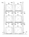
図1は、本発明の実施例による収納棚構造の構成を示す説明図である。この図は、倉庫内に設置された収納棚の一部分を、倉庫内(フォークリフトなどの)通路側から正面視したもので、当該収納棚にパレット21に梱体22を載置して収納した状態を示している。
図示した収納棚の一部分は、柱部10a,10b,10cを等間隔で倉庫の床部60に対して鉛直に設置固定している。ここで例示する収納棚は、上下方向について三段の収納棚を有しており、図示されない倉庫奥側の位置にも、後述するように複数の柱部を備えて構成されている。
An embodiment of the present invention will be described below.
(Example)
FIG. 1 is an explanatory diagram showing a configuration of a storage shelf structure according to an embodiment of the present invention. This figure is a front view of a part of a storage shelf installed in a warehouse from the side of a passage (such as a forklift) in the warehouse, and the
In a part of the illustrated storage shelf, the
柱部10aは、例えば倉庫の壁部側に設置されており、倉庫奥側に設置されている図示されない柱部との間を接続する棚板部12aおよび棚板部13aを、床部60から所定高さの位置に設置固定している。倉庫の床部60を、パレット21を載置する1段目(最下段の収納位置)としたとき、棚板部12aは下から2段目の棚の一部分となり、棚板部13aは最上段の棚の一部分となる。
棚板部12aは、梱体22を載せたパレット21を床部60へ置いたとき、梱体22の最上部が接触せず、また、当該パレット21をフォークリフトで収納、または、搬出するとき、例えば上記の最上部等が接触することのないクリアランスを有する高さ、即ち、パレット21に載置された状態の梱体22の高さ寸法よりも大きな間隔が生じるように設置固定されている。
棚板部13aは、梱体22を載せたパレット21を棚板部12aと後述する棚板部12bに載置したとき、当該梱体22の最上部が接触せず、また、このパレット21をフォークリフトで収納、または搬出するとき、例えば上記の(棚板部12a等に載置された梱体22の)最上部等が接触することのないクリアランスを有する高さに、即ち、パレット21に載置された状態の梱体22の高さ寸法よりも大きな間隔が生じるように設置固定されている。
上記の棚板部12aと棚板部13aは、同一の材料によって構成されており、また、例えば、同一の形状、大きさに形成されたものであり、柱部10a等における設置高さのみが異なるものである。
The
When the
When the
The
柱部10bは、前述の柱部10aから所定距離をおいて設置されており、例えば、柱部10aとの間にパレット21を載置することが可能で、さらに両側方に適当なクリアランス(隙間)が生じる間隔が設けられている。また、柱部10bは、倉庫奥側に設置されている図示されない柱部との間を接続する棚板部12bおよび棚板部13bを、各々所定高さの位置に設置固定している。棚板部12bは、前述の棚板部12aと同一高さに設置されており、棚板部13bは、前述の棚板部13aと同一高さに設置されている。
棚板部12bは、棚板部12aと対向する方向へ(柱部10a側へ向かって)突出するとともに、後述する棚板部12cと対向する方向へ(柱部10c側へ向かって)突出するように設けられている。
棚板部13bは、棚板部13aと対向する方向へ(柱部10a側へ向かって)突出するとともに、後述する棚板部13cと対向する方向へ(柱部10c側へ向かって)突出するように設けられている。
上記の棚板部12bと棚板部13bは、同一の材料によって構成されており、また、例えば、同一の形状、大きさに形成されたものであり、柱部10b等における設置高さのみが異なるものである。
The
The
The
The
柱部10cは、柱部10bから所定距離をおいて設置されており、例えば、柱部10bとの間にパレット21を載置することが可能で、さらに両側方に適当なクリアランス(隙間)が生じる間隔が設けられている。また、柱部10cは、倉庫奥側に設置されている図示されない柱部との間を接続する棚板部12cおよび棚板部13cを、各々所定高さの位置に設置固定している。棚板部12cは、前述の棚板部12a,12b等と同一高さに設置されており、棚板部13cは、前述の棚板部13a,13b等と同一高さに設置されている。
棚板部12cは、棚板部12bと対向する方向へ(柱部10b側へ向かって)突出し、また、図示されない柱部に設置された棚板部と対向するように突出し、棚板部12bと同様な形状に形成されて柱部10cに設置固定されている。
棚板部13cは、棚板部13bと対向する方向へ(柱部10b側へ向かって)突出し、また、図示されない柱部に設置された棚板部と対向するように突出し、棚板部13bと同様な形状に形成されて柱部10cに設置固定されている。
上記の棚板部12cと棚板部13cは、同一の材料によって構成されており、また、例えば、同一の形状、大きさに形成されたものであり、柱部10c等における設置高さのみが異なるものである。
The
The
The
The
図2は、図1の収納棚構造を上方視したときの構成を示す説明図である。この図は、例えば、倉庫内側の2つの壁部61に囲われた角隅部の収納棚を上方視したもので、上記角隅部に設置された収納棚の一部分を示している。なお、図2においては、図1に示した2段目の棚部分を示しており、ここでは、前述の2段目の棚を例示して各部の構成を説明する。2段目以外、即ち、前述の最上段の棚などは、ここで説明する2段目の棚と同様に構成されている。
FIG. 2 is an explanatory diagram showing a configuration when the storage shelf structure of FIG. 1 is viewed from above. This figure shows, for example, a top view of a storage shelf at a corner corner surrounded by two
図1に示した柱部10a〜10cの前方(図2において下方)には、フォークリフト等の通路が設けられている。
柱部10aは、図中側方の壁部61の近傍に設置されており、柱部10aの背後側に柱部20a、柱部30a、柱部40aが、柱部10aと同様に図中側方の壁部61に沿って、倉庫奥側へ向かって(等間隔を空けて)設置されており、倉庫最奥の角隅部に上記の柱部40aが設置されている。これら柱部10a,20a,30a,40aによって支柱列Aを形成している。
柱部10bおよび柱部10cは、前述のように等間隔を空けて収納棚正面側(倉庫の通路側)に設置されており、柱部10bの背後側に柱部20b、柱部30b、柱部40bが設置され、これら柱部10b,20b、30b,40bによって支柱列Bを形成している。
また、柱部10cの背後側に柱部20c、柱部30c、柱部40cが設置され、これら柱部10c,20c,30c,40cによって支柱列Cを形成している。
なお、図2に例示した各柱部は角柱状の形状であるが、梁部材として各棚板部ならびに梁部41等を固定することが可能であれば、円筒状または略H状に形成されたものを用いることも可能である。
A passage such as a forklift is provided in front of the
The
As described above, the
Further, a
Each column portion illustrated in FIG. 2 has a prismatic shape. However, if each shelf plate portion and
倉庫奥側となる図中上方の壁部61に沿って、収納棚の奥端となる位置に柱部40a、柱部40b、柱部40c等が設置されている。
柱部40a、柱部40b、柱部40c等は、適当な位置に梁部41が接合固定されており、各々の位置固定を行うと共に収納棚の剛性を高めている。梁部41は、倉庫奥側の壁部61に沿って設置されて収納棚の背後部分を構成し、倉庫の床面などからの設置位置高さについては、前述の2段目の棚や3段目(最上段)の棚などと同一高さに限定されない。また、収納棚の最奥となる部分においては、梁部41などにパネル等を固定し、図2に示した壁部61等が近傍にないとき、当該収納棚の最奥部分(背面部分)からパレット21もしくは梱体22が落下しないように構成してもよい。
A
The
棚板部12aは、支柱列Aの各柱部を繋ぐように設置され、これら柱部に対して梁部材となって収納棚の強度を確保している。また、棚板部12aは、支柱列Aの各柱部において、例えば倉庫の床部60から同一高さに固定されており、当該床部60に対して水平に設置され、前述のように棚板部12bへ向かって突出している。
棚板部12bは、支柱列Bの各柱部を繋ぐように設置され、これら柱部に対して梁部材となって収納棚の強度を確保している。また、棚板部12aと同様に床部60に対して水平に設置されており、前述の棚板12aと同一高さとなるように構成されている。支柱列Bに設置された棚板部12bは、前述のように棚板部12aへ向かって突出しており、また、棚板部12cへ向かって突出している。
The
The
棚板部12cは、支柱列Cの各柱部を繋ぐように設置され、これら柱部に対して梁部材となって収納棚の強度を確保している。また、棚板部12a,12bと同様に床部60に対して水平に設置されており、前述の棚板12a,12bと同一高さとなるように構成されている。支柱列Cに設置された棚板部12cは、前述のように棚板部12bへ向かって突出しており、また、例えば、支柱列Cの一側方(支柱列Bの反対側)に設置された、図示されない支柱列の棚板部へ向かって突出している。
なお、上記の各棚板部に、図示を省略した複数のローラーを、当該各棚板部の上面から適度に露出させて設置し、収納棚正面と倉庫奥側との間において、パレット21が各棚板部の上面を移動し易くなるように構成してもよい。
これらのローラーは、回転自在に各棚板部に設置されており、当該棚板部の幅員方向において、載置されたパレット21の側方下端部と当接する位置に配置する。また、各棚板部の奥行き方向(収納棚正面、即ちフォークリフト通路側と、倉庫奥側とを結ぶ直線上)において、例えば、1台のパレット21下端部の複数個所と当接する間隔を設けて配置し、当該ローラー上に載置されたパレット21が滑らかに上記の直線上を移動するように備える。
The
It should be noted that a plurality of rollers (not shown) are installed on each shelf board part so as to be appropriately exposed from the upper surface of each shelf board part, and the
These rollers are rotatably installed on each shelf board portion, and are arranged at positions where they contact the lower side ends of the placed
図3は、図1に示したパレット21および梱体22の概観を示す斜視図である。パレット21は、梱体22を載置してフォークリフト等によって移送されるときに変形等を生じない十分な剛性を有するもので、例えば硬質樹脂や木質部材などによって形成されている。
パレット21の上面には、梱体22が載置される平面部位が形成されており、例えば、この平面の縁端(パレット21上面の縁周)には、梱体22に当接して落下を防ぐ周壁が設けられている。
パレット21の正面側となる側面部分には、フォークリフトのフォークを挿入する挿入孔21aが設けられており、例えば、パレット21の正面側とした側面部分から背後側となる側面部分まで貫通するように形成されている。
FIG. 3 is a perspective view showing an overview of the
On the upper surface of the
An
梱体22は、例えば、所定枚数のティッシュペーパーを樹脂製の包装材で包装したピローティッシュ23を縦横に所定個並べ、また、複数段に積載したものを樹脂フィルム材等の梱包シート24によって覆い、1つにまとめて梱包したものである。
ピローティッシュ23は、樹脂製の袋体(薄膜の樹脂シート)等を包装に使用しているため、紙製の箱体を用いて包装したものに比べて、全周囲方向について剛性が弱小である。そのため、これらを複数梱包した梱体22についても、外部から荷重や押圧などが加えられると、内包したティッシュペーパー等が圧縮されてしまい、例えば柔軟な使用感を失うことになる。
そのため、ピローティッシュ23等を梱包した梱体22には、パレット21などの重量物を直接積み上げないようにすることが必要になる。
The
Since the
Therefore, it is necessary not to directly stack heavy objects such as the
図1および図2に示した収納棚は、垂直方向(上下方向)においては、パレット21を1台ずつ各棚板部に載置するように構成されており、詳しくは、支柱列Aと支柱列Bとの間には1台のパレット21のみが載置することができ、また支柱列Bと支柱列Cとの間に1台のパレット21のみが載置できるように構成されている。換言すると、例えば柱部10aと柱部10bとの間隔S2は、1台のパレット21のみを載置できる広さであり、2台以上のパレット21を載置することはできないものである。
The storage shelves shown in FIG. 1 and FIG. 2 are configured to place
上記の間隔S2は、前述のように1台のパレット21もしくは1つの梱体22のみを収納することができ、また、後述するようにフォークリフトが入り込むことができる広さである。
なお、倉庫内において、フォークリフトの通路側に面している各柱部は等間隔を空けて設置されており、柱部10bと柱部10cとの間も間隔S2である。
上記の通路に沿って設置された、即ち、収納棚の正面側に設置されている各柱部の間は、全て間隔S2を空けている。また、これら通路に沿って設置されている各柱部10a,10b,10c等の背後に配置されたそれぞれの柱部についても、上記の通路に沿った方向において間隔S2を空けている。
The interval S2 is a size that can accommodate only one
In addition, in the warehouse, each pillar part facing the passage side of the forklift is installed at equal intervals, and the distance between the
All the pillars installed along the passage, that is, installed on the front side of the storage shelf, have a space S2. Further, the column portions arranged behind the
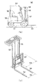
図4は、フォークリフト50の概略構成を示す説明図である。図4(a)は一般的なフォークリフト50を側方視したときの概観を示す説明図で、図4(b)はフォークリフト50に備えられ、パレット21等を移送、または昇降させる際に使用する昇降機構部の概略構成を示す説明図である。
フォークリフト50は、シャシー51に走行用の原動機や車輪等を備え、また、シャシー51の上部には、操作者等が搭乗するシート、操作レバー、各種ペダル、ハンドルなどが配置されたコクピット52を備えている。
コクピット52は、上記のシートに搭乗した操作者等を保護するヘッドガード53によって覆われている。
FIG. 4 is an explanatory diagram showing a schematic configuration of the
The
The
コクピット52の前方(フォークリフト50の前端)には、前述のパレット21の挿入孔21aに挿入させるフォーク54が備えられ、また、当該フォーク54を支持するマスト55が設置されている。例えば、マスト55には、フォーク54を上下方向へ昇降させる動力源の油圧機構部56が設置されており、また、フォーク54には、当該フォーク54と共に昇降し、フォーク54が支持している、またはフォーク54に載置された荷物等を保持するバックレスト57を備えている。上記のフォーク54、マスト55、油圧機構部56、バックレスト57などにより、パレット21もしくは当該パレット21等に載置された梱体を昇降させ、移送の際には、これらを保持する昇降機構部が構成されている。
フォークリフト50の後側には、例えば、上記の昇降機構部にパレット21等を保持させたとき、当該フォークリフト50の姿勢が不安定になることを抑制するバランスウエイト58を備えている。
A
On the rear side of the
図1および図2に示した収納棚は、例えば図4に示したフォークリフト50によってパレット21に載置された梱体22の出し入れを行うように構成されており、前述の間隔S2は、フォークリフト50の全幅よりも広く設定されている。
即ち、収納棚正面(倉庫内の通路)から、例えば柱部10aと柱部10bとの間に、フォークリフト50が入ることができ、さらに倉庫奥側へ進行することができるように各柱部が設置されており、前述の各柱部間の間隔S2は、フォークリフト50の全幅よりも広く、また、図3に示したパレット21の幅員W1よりも適度に広く設けられたものである。
The storage shelves shown in FIGS. 1 and 2 are configured so that the packing
That is, from the front of the storage shelf (passage in the warehouse), for example, the
上記のように、例えば,柱部10aと柱部10bとの間にフォークリフト50が入り込むことができることから、図2に示した棚板部12aと棚板部12bとの間にパレット21を載置するときには、倉庫の奥側から正面へ向かって順に複数台のパレット21を載置(収納)することができ、また、正面側(通路側)に載置されたものから順に搬出することが可能になる。
なお、図2に例示した収納棚は、棚板部12bと棚板部12cとの間においても、フォークリフト50を用いて、倉庫奥側と収納棚正面側(通路側)の間に複数台のパレット21を並べて載置(収納)することができ、また、上記の正面側に載置されたものから搬出することができる。
As described above, for example, since the
Note that the storage shelf illustrated in FIG. 2 includes a plurality of storage shelves between the
パレット21は、2つの支柱列間に載置されることから、各支柱列に設置された棚板部の突出量は、大きすぎる場合にはフォークリフト50に接触することになり、小さすぎる場合にはパレット21を載置できなくなる、または当該パレット21に当接する部位が狭くなることから、小さな外力が加わると容易に2つの棚板部の間に落下することがある。
例えば、棚板部12aと棚板部12bとの間を、図2に示したように間隔S1として開けた場合、この間隔S1は、パレット21の幅員W1よりも狭く、フォークリフト50の所定部位の幅員よりも広く設定されたものである。換言すると、間隔S1は、1台のパレット21の両側方を、各々の棚板部で支持することができるとともに、フォークリフト50が倉庫奥側へ進行するときに障害とならない十分な広さを有するものである。
Since the
For example, when the space between the
具体的には、図3に示したパレット21において、図中左側の側方部位を棚板部12aに載置し、図中右側の側方部位を棚板部12bに載置することが可能な間隔S1を、当該棚板部12aと棚板部12bとの間に空けている。換言すると、これら棚板部は、間隔S1となる突出量(突出長)で、水平方向に突出している。
ここで、棚板部12a,12b等は、所定高さの位置に設置固定されているため、フォークリフト50が収納棚の倉庫奥側へ進行したとき、当該フォークリフト50の下部分とは接触することがない。そのため、棚板部12aと棚板部12bとの間は、フォークリフト50の所定高さ(棚板部12a等が設置されている高さ)以上の部分が進行できる空きがあればよい。即ち、間隔S1は、上記のフォークリフト50の所定高さの部分の幅員以上であればよく、例えば、前述の昇降機構部の最大幅員よりも大きな寸法を有するもので、図3に示した2本のフォーク54の両外側間の幅員W2、バックレスト57の幅員W3などのうち、最大の幅員を上回る大きさであればよい。
Specifically, in the
Here, since the
以上のように支柱列Aに設置された棚板部12a等と支柱列Bに設置された棚板部12b等との間にパレット21を載置するようにしたので、フォークリフト50の通路側の収納棚正面から、当該フォークリフト50が入り込むことができ、収納棚の正面側から倉庫奥側の間に複数のパレット21を並べて収納することができ、パレット21を移動させる機構部分を備えることなく、収納棚の奥側まで梱体22等を収納または搬出することができ、倉庫の設備費用を抑制しながら、効率よく多数の梱体22を倉庫内に収納することが可能になる。また、フォークリフト50の通路を収納棚の正面側に設けるだけでよいので、倉庫の総面積を抑制しながら、多数の梱体22を収納することが可能になる。
ここで、本実施例において説明した収納棚は、各棚板部を片持ちとして固定することを特徴としているが、上記の収納棚に収納する梱体22は、多数の積み上げを避けたい剛性の小さい包装体を用いた、例えば、ピローティッシュ23などである。そのため、これらを多数梱包した梱体22の総重量も比較的軽量になり、当該梱体22をパレット21に載置し、このパレット21を上記の片持ち棚板部へ載置しても十分に耐えられるように構成することが可能となる。
As described above, since the
Here, the storage shelf described in the present embodiment is characterized in that each shelf plate portion is fixed as a cantilever. However, the packing
10a〜10c柱部
12a〜12c,13a〜13c棚板部
20a〜20c柱部
21パレット
21a挿入孔
22梱体
23ピローティッシュ
24梱包シート
30a〜30c,40a〜40c柱部
41梁部
50フォークリフト
51シャシー
52コクピット
53ヘッドガード
54フォーク
55マスト
56油圧機構部
57バックレスト
58バランスウエイト
60床部
61壁部
10a-
Claims (5)
梱体を載置するパレットの第1の側方に設置される複数の柱部からなる第1支柱列と、
前記パレットの第2の側方に設置される複数の柱部からなる第2支柱列と、
水平方向に延設されて前記第1支柱列の各柱部を所定高さの位置で接続する第1棚板部と、
水平方向に延設されて前記第2支柱列の各柱部を所定高さの位置で接続する第2棚板部と、
を備え、
前記第1支柱列および前記第2支柱列は、前記パレットを移送するフォークリフトの通路側から前記倉庫の奥側までの間に設置され、前記第1支柱列と前記第2支柱列との間に前記パレットを1台のみ載置することが可能であるとともに前記フォークリフトの全幅よりも広い間隔を有しており、
前記第1棚板部および前記第2棚板部は、相互に対向するように同一高さに設置され、前記第1棚板部に前記パレットの第1の側方の部位を載置するとともに前記第2棚板部に前記パレットの第2の側方の部位を載置することが可能なように、相互に対向する棚板部へ向かって突出しており、
前記第1棚板部と前記第2棚板部との間隔は、前記フォークリフトの所定部位の幅員よりも広い、
ことを特徴とする収納棚構造。 A storage shelf structure installed in a warehouse,
A first support column comprising a plurality of pillars installed on the first side of the pallet on which the package is placed;
A second support column comprising a plurality of pillars installed on the second side of the pallet;
A first shelf that extends in the horizontal direction and connects each column of the first column of columns at a predetermined height;
A second shelf that extends in the horizontal direction and connects each column of the second column of columns at a predetermined height;
With
The first strut row and the second strut row are installed between the forklift passage side for transferring the pallet and the back side of the warehouse, and between the first strut row and the second strut row. It is possible to place only one pallet and has a wider interval than the full width of the forklift,
The first shelf part and the second shelf part are installed at the same height so as to face each other, and the first side part of the pallet is placed on the first shelf part. Projecting toward the mutually opposing shelf parts so that the second side part of the pallet can be placed on the second shelf part,
An interval between the first shelf board part and the second shelf board part is wider than a width of a predetermined part of the forklift,
A storage shelf structure characterized by that.
ことを特徴とする請求項1に記載の収納棚構造。 The first support column and the second support column are provided from the passage side of the forklift in the warehouse toward the back side of the warehouse, and the first support column and the second support column along the passage. Are arranged,
The storage shelf structure according to claim 1.
ことを特徴とする請求項1または請求項2に記載の収納棚構造。 The first shelf board part and the second shelf board part form a plurality of shelves with an interval larger than the height dimension of the package placed on the pallet in the height direction of the pillar part. A plurality of the pillars are installed so as to
The storage shelf structure according to claim 1, wherein the storage shelf structure is a storage shelf structure.
ことを特徴とする請求項1から3のいずれか1項に記載の収納棚構造。 The distance between the first shelf board part and the second shelf board part is wider than at least the width of the part of the installation height of the first shelf board part and the second shelf board part of the forklift,
The storage shelf structure according to any one of claims 1 to 3, wherein
ことを特徴とする請求項1から4のいずれか1項に記載の収納棚構造。 The first shelf board part and the second shelf board part are placed on the first shelf board part and the second shelf board part on a straight line connecting the passage side of the forklift and the back side of the warehouse. A plurality of rollers for moving the pallet;
The storage shelf structure according to any one of claims 1 to 4, wherein the storage shelf structure is provided.
Priority Applications (2)
| Application Number | Priority Date | Filing Date | Title |
|---|---|---|---|
| JP2016254639A JP2018104174A (en) | 2016-12-28 | 2016-12-28 | Storage shelf structure |
| PCT/JP2017/037625 WO2018123218A1 (en) | 2016-12-28 | 2017-10-18 | Storage rack structure |
Applications Claiming Priority (1)
| Application Number | Priority Date | Filing Date | Title |
|---|---|---|---|
| JP2016254639A JP2018104174A (en) | 2016-12-28 | 2016-12-28 | Storage shelf structure |
Publications (2)
| Publication Number | Publication Date |
|---|---|
| JP2018104174A true JP2018104174A (en) | 2018-07-05 |
| JP2018104174A5 JP2018104174A5 (en) | 2018-09-27 |
Family
ID=62710325
Family Applications (1)
| Application Number | Title | Priority Date | Filing Date |
|---|---|---|---|
| JP2016254639A Pending JP2018104174A (en) | 2016-12-28 | 2016-12-28 | Storage shelf structure |
Country Status (2)
| Country | Link |
|---|---|
| JP (1) | JP2018104174A (en) |
| WO (1) | WO2018123218A1 (en) |
Cited By (1)
| Publication number | Priority date | Publication date | Assignee | Title |
|---|---|---|---|---|
| CN112722661A (en) * | 2020-12-25 | 2021-04-30 | 江苏大学 | Opening-closing type self-adaptive adjusting device for medicine tank clutch of vertical medicine dispensing machine |
Families Citing this family (1)
| Publication number | Priority date | Publication date | Assignee | Title |
|---|---|---|---|---|
| CN109230153A (en) * | 2018-08-07 | 2019-01-18 | 安徽高山智能装备有限公司 | A kind of raw material shelf convenient for classification |
Citations (3)
| Publication number | Priority date | Publication date | Assignee | Title |
|---|---|---|---|---|
| JP2003312815A (en) * | 2002-04-24 | 2003-11-06 | Murata Mach Ltd | Fall-down shelf type drive-in rack |
| JP2006160453A (en) * | 2004-12-08 | 2006-06-22 | Hamanaka Nut Kk | Rack facility |
| US20150101998A1 (en) * | 2013-10-11 | 2015-04-16 | Steel King Industries, Inc. | Double-Wide Drive-In Storage Rack Assembly with Dual-Rail Truss-Beam |
-
2016
- 2016-12-28 JP JP2016254639A patent/JP2018104174A/en active Pending
-
2017
- 2017-10-18 WO PCT/JP2017/037625 patent/WO2018123218A1/en active Application Filing
Patent Citations (3)
| Publication number | Priority date | Publication date | Assignee | Title |
|---|---|---|---|---|
| JP2003312815A (en) * | 2002-04-24 | 2003-11-06 | Murata Mach Ltd | Fall-down shelf type drive-in rack |
| JP2006160453A (en) * | 2004-12-08 | 2006-06-22 | Hamanaka Nut Kk | Rack facility |
| US20150101998A1 (en) * | 2013-10-11 | 2015-04-16 | Steel King Industries, Inc. | Double-Wide Drive-In Storage Rack Assembly with Dual-Rail Truss-Beam |
Cited By (2)
| Publication number | Priority date | Publication date | Assignee | Title |
|---|---|---|---|---|
| CN112722661A (en) * | 2020-12-25 | 2021-04-30 | 江苏大学 | Opening-closing type self-adaptive adjusting device for medicine tank clutch of vertical medicine dispensing machine |
| CN112722661B (en) * | 2020-12-25 | 2022-02-15 | 江苏大学 | Opening-closing type self-adaptive adjusting device for medicine tank clutch of vertical medicine dispensing machine |
Also Published As
| Publication number | Publication date |
|---|---|
| WO2018123218A1 (en) | 2018-07-05 |
Similar Documents
| Publication | Publication Date | Title |
|---|---|---|
| KR20120068688A (en) | Method for transporting concentrated mass loads by container | |
| JP2012140139A (en) | Glass sheet packing container and conveying method using the same | |
| WO2018123218A1 (en) | Storage rack structure | |
| US9873548B2 (en) | Extensible pallet rotation apparatus | |
| JPH09295686A (en) | Glass tube packaging body | |
| JP2014069594A (en) | Pallet transportation truck | |
| JP3209947U (en) | Glass plate package | |
| JP4924219B2 (en) | Pallet material | |
| JP3220466U (en) | Plastic plate storage case | |
| JP2012254807A (en) | Plate-like body packaging, and stacking method therefor | |
| JP3189533U (en) | Container trolley | |
| CN217598646U (en) | Turnover dolly convenient to stack | |
| JP4984293B2 (en) | Transportation cart and pallet | |
| KR101486045B1 (en) | Pallet for transporting steel sheet and storing lamination layer | |
| JP3233887U (en) | Packing body | |
| JP7125375B2 (en) | Automated warehouse system | |
| JP4440756B2 (en) | Shelf equipment | |
| CN110294169B (en) | Universal positioning platform | |
| KR200407564Y1 (en) | Heavy Load Table | |
| TW202134143A (en) | Packaging container, packaging method, and metal foil transport method | |
| TW202136143A (en) | Packaging container, packaging method, and method for transporting metal foil | |
| JP3175431U (en) | Trolley | |
| JP3288851B2 (en) | Loading assistance equipment | |
| JP2016199305A (en) | Packing box | |
| JP2021102465A (en) | Transportation box unit |
Legal Events
| Date | Code | Title | Description |
|---|---|---|---|
| A521 | Request for written amendment filed |
Free format text: JAPANESE INTERMEDIATE CODE: A523 Effective date: 20180813 |
|
| A621 | Written request for application examination |
Free format text: JAPANESE INTERMEDIATE CODE: A621 Effective date: 20180813 |
|
| A871 | Explanation of circumstances concerning accelerated examination |
Free format text: JAPANESE INTERMEDIATE CODE: A871 Effective date: 20180813 |
|
| A975 | Report on accelerated examination |
Free format text: JAPANESE INTERMEDIATE CODE: A971005 Effective date: 20180815 |
|
| A131 | Notification of reasons for refusal |
Free format text: JAPANESE INTERMEDIATE CODE: A131 Effective date: 20180918 |
|
| A521 | Request for written amendment filed |
Free format text: JAPANESE INTERMEDIATE CODE: A523 Effective date: 20181113 |
|
| A02 | Decision of refusal |
Free format text: JAPANESE INTERMEDIATE CODE: A02 Effective date: 20190205 |