JP2018100809A - Air blower and dust-proof filter used for air blower - Google Patents
Air blower and dust-proof filter used for air blower Download PDFInfo
- Publication number
- JP2018100809A JP2018100809A JP2016247944A JP2016247944A JP2018100809A JP 2018100809 A JP2018100809 A JP 2018100809A JP 2016247944 A JP2016247944 A JP 2016247944A JP 2016247944 A JP2016247944 A JP 2016247944A JP 2018100809 A JP2018100809 A JP 2018100809A
- Authority
- JP
- Japan
- Prior art keywords
- filter
- shutter
- blower
- opening
- frame
- Prior art date
- Legal status (The legal status is an assumption and is not a legal conclusion. Google has not performed a legal analysis and makes no representation as to the accuracy of the status listed.)
- Granted
Links
Images


Abstract
Description
本発明は、フィルターを備えたフィルター付の送風機および送風機に用いられるフィルターに関する。 The present invention relates to a filter-equipped blower provided with a filter and a filter used in the blower.
熱交換機器用のフィルターの従来例として、熱交換機器の送風機の給気口と、送風機内部の熱交換素子との間に設けられているものが知られている。この送風機内部には、フィルターを送風機に取り付けるための取付部が設けられている。 As a conventional example of a filter for a heat exchange device, a filter provided between an air supply port of a blower of the heat exchange device and a heat exchange element inside the blower is known. An attachment portion for attaching the filter to the blower is provided inside the blower.
フィルターを取付部から取り外し、フィルターに捕集された捕集物を取り除くことで、熱交換素子の目づまりを防止することができる(例えば、特許文献1参照)。 By removing the filter from the attachment portion and removing the collected matter collected by the filter, clogging of the heat exchange element can be prevented (see, for example, Patent Document 1).
このような従来のフィルター付送風機においては、フィルターを取付部から取り外す際に、フィルター開口領域が給気口に対して開いているため、捕集物がフィルターの外に落下してしまうという課題を有していた。 In such a conventional fan with a filter, when removing the filter from the mounting portion, the filter opening region is open with respect to the air supply port, so the problem that the collected matter falls out of the filter. Had.
そこで本発明は、上記従来の課題を解決するものであり、フィルターを取付部から取り外す際に、フィルターに捕集された捕集物がフィルターの外に落下することを抑えるフィルター付送風機を提供することを目的とする。 Then, this invention solves the said conventional subject, and provides a fan with a filter which suppresses that the collection thing collected by the filter falls outside a filter, when removing a filter from an attachment part. For the purpose.
本発明の一態様に係る送風機は、給気口および排気口を有する送風機において、送風機は、内部に設けられる送風部と、送風部により前記給気口から吸い込まれた空気が開口部を通って、フィルターを通過するように設けられた防塵部と、防塵部の開口部の開口面に沿って摺動するように防塵部に取り付けられたフィルターシャッターとを備え、防塵部は、送風機に取り外し可能に係止されており、防塵部を送風機から取り外す際に、フィルターシャッターが摺動し、フィルターシャッターの一部が防塵部の開口部を覆う構成としたものであり、これにより所期の目的を達成するものである。 The blower according to one aspect of the present invention is a blower having an air supply port and an exhaust port. The blower includes an air blower provided inside, and air sucked from the air supply port by the air blower through the opening. , Equipped with a dustproof part provided to pass through the filter, and a filter shutter attached to the dustproof part so as to slide along the opening surface of the opening of the dustproof part, the dustproof part is removable to the blower When the dustproof part is removed from the blower, the filter shutter slides so that a part of the filter shutter covers the opening of the dustproof part. To achieve.
本発明によれば、フィルターに捕集された捕集物の落下を抑えながら、送風機から防塵部を容易に取り外すことが可能である送風機を提供できる。 ADVANTAGE OF THE INVENTION According to this invention, the air blower which can remove a dustproof part easily from an air blower can be provided, suppressing fall of the collection thing collected by the filter.
以下、本発明の実施の形態を図面に基づいて説明する。ただし、以下に示す実施の形態は、本発明の技術思想を具体化するための送風機を例示するものであって、本発明は送風機を以下のものに特定しない。また、特許請求の範囲に示される部材を、実施例の部材に特定するものでは決してない。特に実施の形態に記載されている構成部材の寸法、材質、形状、その相対的配置等は特に特定的な記載がない限りは、本発明の範囲をそれのみに限定する趣旨ではなく、単なる説明例にすぎない。なお、各図面が示す部材の大きさや位置関係等は、説明を明確にするため誇張していることがある。さらに以下の説明において、同一の名称、符号については同一もしくは同質の部材を示しており、詳細説明を適宜省略する。さらに、本発明を構成する各要素は、複数の要素を同一の部材で構成して一の部材で複数の要素を兼用する態様としてもよいし、逆に一の部材の機能を複数の部材で分担して実現することもできる。また、一部の実施例、実施形態において説明された内容は、他の実施例、実施形態等に利用可能なものもある。 Hereinafter, embodiments of the present invention will be described with reference to the drawings. However, embodiment shown below illustrates the air blower for embodying the technical idea of this invention, and this invention does not specify an air blower to the following. Moreover, the member shown by the claim is not what specifies the member of an Example at all. In particular, the dimensions, materials, shapes, relative arrangements, and the like of the constituent members described in the embodiments are not intended to limit the scope of the present invention only to the description unless otherwise specified. It is just an example. Note that the size, positional relationship, and the like of the members shown in each drawing may be exaggerated for clarity of explanation. Furthermore, in the following description, the same name and symbol indicate the same or the same members, and detailed description thereof will be omitted as appropriate. Furthermore, each element constituting the present invention may be configured such that a plurality of elements are constituted by the same member and the plurality of elements are shared by one member, and conversely, the function of one member is constituted by a plurality of members. It can also be realized by sharing. In addition, the contents described in some examples and embodiments may be used in other examples and embodiments.
本発明の一態様に係る送風機は、給気口および排気口を有する送風機と、送風機内に設けられる送風部と、送風部により給気口から吸い込まれた給気流Aが開口部を通って、フィルターを通過するように設けられた防塵部と、防塵部の開口部の開口面に沿って摺動するように防塵部に取り付けられたフィルターシャッターとを備えた送風機であって、防塵部は、送風機に取り外し可能に係止されており、防塵部を送風機から取り外す際に、フィルターシャッターが摺動し、フィルターシャッターの一部が防塵部の開口部を覆う構成を有している。 The blower according to one embodiment of the present invention includes a blower having an air supply port and an exhaust port, a blower provided in the blower, and a supply airflow A sucked from the supply port by the blower through the opening. A blower comprising a dustproof portion provided to pass through a filter and a filter shutter attached to the dustproof portion so as to slide along the opening surface of the opening of the dustproof portion, wherein the dustproof portion is The filter shutter is detachably locked to the blower, and when removing the dustproof part from the blower, the filter shutter slides and a part of the filter shutter covers the opening of the dustproof part.
これにより、送風機に取り外し可能な状態で係止された防塵部を送風機から取り外す際に、防塵部のフィルターシャッターを摺動させ、フィルターシャッターの一部がフィルター開口部を覆う構成とすることで、送風機から防塵部を取り外す際に、防塵部のフィルターに捕集された捕集物がフィルター開口部から落下することを防止することができる。すなわち、フィルターに捕集された捕集物の落下を抑えながら、防塵部を送風機から取り外してメンテナンスを行なうことができるという効果を備える。 By this, when removing the dustproof part locked in a state where it can be removed from the blower from the blower, the filter shutter of the dustproof part is slid, and a part of the filter shutter covers the filter opening. When removing the dustproof part from the blower, it is possible to prevent the collected matter collected by the filter of the dustproof part from falling from the filter opening. That is, it is possible to perform maintenance by removing the dustproof part from the blower while suppressing the fall of the collected matter collected by the filter.
また、本発明において、防塵部は、平板状のフレームとフィルターとの間にフィルターシャッターを配置することで、防塵部の開口部を塞ぐシャッター構造をフレーム、フィルターシャッター、フィルターの3つの部材によって簡易に形成できる。 Further, in the present invention, the dustproof portion is arranged by arranging a filter shutter between the flat frame and the filter, so that the shutter structure for closing the opening of the dustproof portion can be simplified by three members of the frame, the filter shutter, and the filter. Can be formed.
また、本発明において、フィルターは、袋状のメッシュ部材とメッシュ部材の開口側を連結する枠体とを備えており、フィルターシャッターは、開口部を形成するフィルターシャッター開口部とフィルターシャッター開口部の周囲からフィルター側に立設する側壁ガイドを備えており、枠体と側壁ガイドとが異なる二面で当接している構成によって、フィルターの枠体とフィルターシャッターの側壁ガイドとの間からメッシュ部材の内部に集塵した塵埃、虫類の飛散を防止することができる。 In the present invention, the filter includes a bag-like mesh member and a frame body that connects the opening side of the mesh member, and the filter shutter includes a filter shutter opening portion that forms the opening portion and a filter shutter opening portion. A side wall guide standing on the filter side from the surroundings is provided, and the mesh member is arranged between the filter frame and the filter shutter side wall guide by a configuration in which the frame and the side wall guide are in contact with each other on two different surfaces. It is possible to prevent dust and insects collected inside from being scattered.
また、本発明において、フィルターシャッターのフレームに対向する側に設けられたシャッター摺動リブとフレームのフィルターシャッター側に設けられたフレーム摺動リブとが仮固定可能なように係止する構成によって、フィルターシャッターの摺動リブとフレームの摺動リブとが係止することでフィルターシャッターの摺動運動を仮固定することができる。 In the present invention, the shutter sliding rib provided on the side of the filter shutter facing the frame and the frame sliding rib provided on the filter shutter side of the frame are locked so as to be temporarily fixed. The sliding movement of the filter shutter can be temporarily fixed by the sliding rib of the filter shutter and the sliding rib of the frame being locked.
また、本発明の防塵フィルターは、給気口および排気口を有する風路に取り付けられる防塵フィルターであって、給気口から吸い込まれた空気が開口部を通って、フィルターを通過するように設けられた防塵部と、開口部の開口面に沿って摺動するように防塵部に取り付けられたフィルターシャッターとを備え、防塵部は、前記風路に取り外し可能に固定されており、防塵部を風路から取り外す際に、フィルターシャッターが摺動し、フィルターシャッターの一部が開口部を覆う構成とすることで、送風機等から防塵部を取り外す際に、防塵部のフィルターに捕集された捕集物がフィルター開口部から落下することを防止することができる。 The dustproof filter of the present invention is a dustproof filter attached to an air passage having an air supply port and an exhaust port, and is provided so that air sucked from the air supply port passes through the filter through the opening. And a filter shutter attached to the dust-proof portion so as to slide along the opening surface of the opening.The dust-proof portion is detachably fixed to the air passage, and the dust-proof portion is When removing from the air passage, the filter shutter slides and a part of the filter shutter covers the opening, so that when the dust proof part is removed from the blower, etc. The collected material can be prevented from falling from the filter opening.
以下、本発明の実施の形態について図面を参照しながら説明する。 Hereinafter, embodiments of the present invention will be described with reference to the drawings.
(実施の形態1)
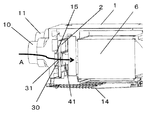
図1に示すように、送風機1は箱型であり、送風機1の一側面から突出するように給気口10および排気口11が設けられている。また、一側面に対向する他の側面には、給気口10より吸引され、排気によって熱交換された空気を供給する供給口12および排気を送風機に吸引する排気給気口13とが設けられている。
(Embodiment 1)
As shown in FIG. 1, the
図1の送風機1の底面には着脱自在の点検パネル14が設けられており、点検パネル14は送風機1の底面より取り外しが可能な構成となっている。
A
図2は、送風機1の部分断面斜視図であり送風部16は、ファンとモーターとを含んで構成されている。送風部16は、熱交換素子に隣接して設けられており、給気用送風部および排気用送風部が設けられている。なお、ファン、モーター、熱交換素子、給気用送風部、排気用送風部は図示を省略している。
FIG. 2 is a partial cross-sectional perspective view of the
この送風機1は、例えば、建物の天井裏等に設置される。
The
図2で示される送風機1によって給気口10から送風機1に吸い込まれた空気は、供給口12から吹き出される。図2の給気流Aは、給気口10から送風機1に吸い込まれた空気が送風機1の内部の一部を通過する状態を表している。なお、給気される空気は、一般に室外空気であるが室内空気であってもよく、送風機1より供給される空気は一般に室内へ向かう空気である。なお、給気口10、排気口11、供給口12、排気給気口に風路ダクトを接続してもよい。
Air sucked into the
図2に示すように給気口10の気流方向の下流近傍には、送風機1内部の送風部16の保護や供給する空気の浄化を目的として防塵部2を備える。防塵部2は給気口10と送風部16との間に設けられている。防塵部2は、図8に示すフレーム3のフレーム開口ガイド31と給気口10から内部方向に突出するダクト15とが係止することで防塵部2が送風機1内に係止されている。
As shown in FIG. 2, a
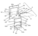
防塵部2は、図4の防塵部2の斜視図および図6の防塵部2の分解斜視図で示されるように、フレーム3とフィルター4とフィルターシャッター5とで構成されている。また、フィルター4はメッシュ部材41と枠体42とで構成されている。この構成によって、図2で示すように送風機1の給気口10から吸い込まれた給気流Aはフレーム開口部30を通って、メッシュ部材41を通過する。給気口10から吸い込まれた空気が防塵部2のメッシュ部材41を通過することで、給気口10から吸い込まれた空気中に浮遊する塵埃や虫類をメッシュ部材41により捕集することが可能である。
As shown in the perspective view of the
図4に示すように、防塵部2は給気口10側よりフレーム3、フィルターシャッター5、フィルター4の順に配置されている。フレーム3、フィルターシャッター5、フィルター4はともに開口部を設けた構成であり、給気口10から吸い込まれた給気流Aは、フレーム開口部30、フィルターシャッター開口部50、フィルター開口部40を順に通過し、フィルター4のメッシュ部材41を通過する構成となっている。フレーム3、フィルターシャッター5、フィルター4の3つの簡易な構成でフレーム3とフィルター4との間にフィルターシャッター5を配置することが可能である。また、図2に示すように、防塵部は給気口10側から平板状のフレーム、フィルターシャッター、フィルターの順に配置されている。なお、図示はしないが他の防塵部の実施形態として、給気口10側からフィルターシャッター5、フレーム3、フィルターの順に配置することも可能である。
As shown in FIG. 4, the
図6に示すようにフレーム3は、四角形の薄板状であり、フレーム中央に開口したフレーム開口部30を備えている。フレーム3のフィルター4が配置される側の一面には、フレーム開口部30の両側に沿って鉛直方向に延在するように、フィルター4側に立設した一対のフレーム内側ガイド32が設けられており、一対のフレーム内側ガイドの鉛直方向の上端を連結するようにフレーム内側ガイド連結片32aが設けられている。よって、一対のフレーム内側ガイド32と一対のフレーム内側ガイドの鉛直方向の上端を連結連したフレーム内側ガイド連結片32aは、フィルター4側から見て平面視コの字状の形状をしている。フレーム内側ガイド32の鉛直方向の長さはフレーム開口部30の鉛直方向の長さよりも長い形状である。さらに、フレーム3のフィルター4側の一面には、フレーム3の両側面よりひさし状にフィルター4側に立設するフレーム外側ガイド33が形成されている。また、フレーム3のフィルター4側の一面には、フレーム開口部30の下部に摺動凸リブ36が設けられている。
As shown in FIG. 6, the
次に、図8を用いてフレーム3を詳述する。図8に示すようにフレーム3の給気口10側の一面には、フレーム開口部30の周囲を囲うようにフレーム3から立設したフレーム開口ガイド31が形成されている。
Next, the
次に、図6を用いてフィルターシャッター5を詳述する。図6に示すようにフィルターシャッター5は、四角形状の平板状であり、フィルターシャッター5の上部にはシャッター部51が設けられ、シャッター部51の下部に開口したフィルターシャッター開口部50を備えている。フィルターシャッター5のフィルター4側の一面には、フィルターシャッター5の周縁およびフィルターシャッター開口部50の上辺および下辺には、フィルター4側に立設する側壁ガイド52が形成されている。またフィルターシャッター開口部50の上部には、側壁ガイド52より延設するように一対の第一摺動凹リブ54aが設けられている。さらにフィルターシャッター開口部50の下部にもフィルターシャッター5の側縁の側壁ガイド52より延設するように一対の第二摺動凹リブ54bが設けられている。
Next, the
図4および図5に示すように、フィルターシャッター5はフレーム3のフィルター4側の一面に対向して配置される。フィルターシャッター5の側壁ガイド52は、フレーム3のフレーム内側ガイド32の内周側に当設するように配置されており、図4及び図5の矢印の鉛直方向に摺動可能な構成である。すなわち、フィルターシャッター5を図4及び図5の矢印の鉛直方向に摺動する際にフレーム3のフレーム内側ガイド32が摺動運動のガイドとして機能している。図4は、フィルターシャッター開口部50とフレーム開口部30およびフィルター開口部40とが連通した状態である。図5はフィルターシャッター5が鉛直方向に垂下するように摺動し、フィルターシャッター開口部50とフレーム開口部30およびフィルター開口部40とが連通しない状態、すなわちフィルターシャッター5のシャッター部51がフレーム開口部30およびフィルター開口部40を遮断した状態である。
As shown in FIGS. 4 and 5, the
フィルターシャッター5は、摺動可能な構造でフレーム3に取り付けられているが、フィルターシャッター5の第一摺動凹リブ54a及び第二摺動凹リブ54bとフレーム3の摺動凸リブ36とが係止することでフィルターシャッター5の摺動運動を仮固定することができる。フィルターシャッター5の第一摺動凹リブ54a及び第二摺動凹リブ54bとが鉛直方向に異なる位置に別途設けられている構成とすることで、図4のフィルターシャッター開口部50とフィルター開口部40とが連通した状態(第二摺動凹リブ54bと摺動凸リブ36とが係止している状態)、及び図5のシャッター部51がフィルター開口部40を覆った状態(第一摺動凹リブ54aと摺動凸リブ36とが係止している状態)でのフィルターシャッター5の摺動方向における仮固定がなされる。この構成によって、フィルターシャッター5が仮固定されることで、自然にフィルターシャッター5が摺動することを防止できるという効果を備える。また、上述の構成によって、フィルターシャッター5がフレーム3に仮固定されることで、作業者が送風機1より防塵部2を取り外す際にフィルターシャッター5が摺動し、シャッター部51がフィルター開口部40より位置ずれすることによるフィルター4内に捕集された塵埃や虫類の散乱を防止することができる。さらに、上述の構成によって、フィルターシャッター5フレーム3に仮固定されることで、送風機1内に取り付けられた防塵部2が、送風機1の可動中にフィルターシャッター5がフィルターシャッター開口部50とフィルター開口部40とが連通した状態から鉛直方向に下向きに摺動し、シャッター部51がフィルター開口部40を覆うことによる送風機1の圧損を防止することができる。
The
次に、送風機1から防塵部2を取り外す構成について説明する。図1及び図2に記載された送風機1の点検パネル14を取り外した状態において、防塵部2のフィルターシャッター5の取っ手53を図4の矢印である鉛直方向下向きに移動させ、防塵部2を送風機1から取り外すことができる。また、取り外した防塵部2を送風機1に取り付ける場合は、図1及び図2に記載された送風機1の点検パネル14を取り外した状態において、防塵部2のフィルターシャッター5の取っ手53を図5の矢印である鉛直方向上向きに移動させ、防塵部2を送風機1に取り付けることができる。
Next, the structure which removes the
この構成によって、送風機1に取り外し可能な状態で固定された防塵部2を送風機1から取り外す際に、防塵部2のフィルターシャッター5を鉛直方向下向きに摺動させ、フィルターシャッター5のシャッター部51がフィルター開口部40を覆う図5で示す構成とすることで、送風機1から防塵部2を取り外す際に、防塵部2のフィルター4に捕集された捕集物がフィルター開口部40から落下することを防止することができる。すなわち、フィルター4に捕集された捕集物の落下を抑えながら、防塵部2を送風機1から取り外してメンテナンスを行なうことができるという効果を備える。
With this configuration, when removing the
図6に示すようにフィルター4は、開口したフィルター開口部40を備えた袋状のメッシュ部材41とメッシュ部材41のフィルター開口部40の側縁と接合された枠体42とで構成されている。塵埃及び虫類を捕集するために、メッシュ部材41のメッシュ間隔は、例えば0.01mm〜1mmであることが望ましい。
As shown in FIG. 6, the
図6に示すようにフィルター4の枠体42とフレーム3とは、係止構造によって固定されている。一方の係止構造は、フレーム内側ガイド32の側壁に設けられた係止凹部34と図5に図示された枠体42に設けられた係止凸部43とが嵌合し、固定される。また他方の係止構造は、フレーム3のフレーム外側ガイド33に設けられた係止リブ35と、枠体42に設けられた弾性リブ44とが当接して固定される。
As shown in FIG. 6, the
図7は、フィルターシャッター5のフィルターシャッター開口部50とフレーム開口部30とが連通した状態において、フィルター4の枠体42とフィルターシャッター5の側壁ガイド52とが係合している構成を示した斜視断面図である。枠体42のフィルターシャッター5側の端面のうち上辺及び下辺には、ガイド溝45が設けられている。この枠体42のガイド溝45に対して、フィルターシャッター5の側壁ガイド52の端面と側面の異なる2面とで当接している。この構成によって、フィルターシャッター5とフィルター4の枠体42との間隙を低減することが可能であり、フィルター4のメッシュ部材41の内部に捕集した塵埃や虫類の拡散を防止する効果を備えている。
FIG. 7 shows a configuration in which the
図3に示すように送風機1の給気口10のダクト15と防塵部2のフレーム開口ガイド31とは着脱可能な構成で係止している。メンテナンス時は図2で記載の点検パネル14を取り外した後、給気口10のダクト15に係止される防塵部2のフレーム開口ガイド31を取り外し、防塵部2のフィルターシャッター5の取っ手53を押し下げることでシャッターが閉まり作業者は容易に防塵部2を送風機1から取り外すことが可能である。
As shown in FIG. 3, the
本発明により、作業者は、防塵部2の取っ手53を押し下げることで容易に送風機1から防塵部2を取り外すことが可能であり、さらに防塵部2のフィルターシャッター5が鉛直方向下向きに摺動し、シャッター部51がフィルター開口部40を覆うことでフィルター4に捕集された捕集物がフィルター開口部40から落下することを防止することができる。
According to the present invention, the operator can easily remove the dust-
本発明に係る送風機は、フィルターを搭載する換気扇や熱交換機器等の換気送風装置全般に適用可能である。また、本発明に係る防塵フィルターは、外気を取り込む送風機等に利用可能である。 The blower according to the present invention can be applied to general ventilation fans such as a ventilation fan and a heat exchange device equipped with a filter. In addition, the dustproof filter according to the present invention can be used for a blower that takes in outside air.
1 送風機
10 給気口
11 排気口
12 供給口
13 排気給気口
14 点検パネル
15 ダクト
16 送風部
2 防塵部
3 フレーム
30 フレーム開口部
31 フレーム開口ガイド
32 フレーム内側ガイド
33 フレーム外側ガイド
34 係止凹部
35 係止リブ
36 摺動凸リブ
4 フィルター
40 フィルター開口部
41 メッシュ部材
42 枠体
43 係止凸部
44 弾性リブ
45 ガイド溝
5 フィルターシャッター
50 フィルターシャッター開口部
51 シャッター部
52 側壁ガイド
53 取っ手
54a 第一摺動凹リブ
54b 第二摺動凹リブ
A 給気流
DESCRIPTION OF
Claims (6)
前記送風機は、内部に設けられる送風部と、
前記送風部により前記給気口から吸い込まれた空気が開口部を通って、フィルターを通過するように設けられた防塵部と、
前記防塵部の前記開口部の開口面に沿って摺動するように前記防塵部に取り付けられたフィルターシャッターとを備え、
前記防塵部は、前記送風機に取り外し可能に係止されており、
前記防塵部を前記送風機から取り外す際に、前記フィルターシャッターが摺動し、前記フィルターシャッターの一部が前記防塵部の前記開口部を覆うことを特徴とする送風機。 In a blower having an air supply port and an exhaust port,
The blower includes a blower provided inside,
A dust-proof part provided so that the air sucked from the air supply port by the air blowing part passes through the opening and the filter;
A filter shutter attached to the dustproof part so as to slide along the opening surface of the opening of the dustproof part,
The dustproof part is detachably locked to the blower,
When removing the dustproof part from the blower, the filter shutter slides, and a part of the filter shutter covers the opening of the dustproof part.
前記フィルターシャッターは、前記開口部を形成するフィルターシャッター開口部と前記フィルターシャッター開口部の周囲から前記フィルター側に立設する側壁ガイドを備えており、前記枠体と前記側壁ガイドとが異なる二面で当接していることを特徴とする請求項1または2に記載の送風機。 The filter includes a bag-shaped mesh member and a frame that connects the opening side of the mesh member;
The filter shutter includes a filter shutter opening that forms the opening and a side wall guide that stands on the filter side from the periphery of the filter shutter opening, and the frame and the side wall guide are different from each other. The blower according to claim 1, wherein the blower is in contact with each other.
前記給気口から吸い込まれた空気が開口部を通って、フィルターを通過するように設けられた防塵部と、
前記開口部の開口面に沿って摺動するように前記防塵部に取り付けられたフィルターシャッターとを備え、
前記防塵部は、前記風路に取り外し可能に固定されており、
前記防塵部を前記風路から取り外す際に、前記フィルターシャッターが摺動し、前記フィルターシャッターの一部が開口部を覆うことを特徴とする防塵フィルター。 A dustproof filter attached to an air passage having an air supply port and an exhaust port,
A dust-proof part provided so that the air sucked from the air supply port passes through the filter through the opening;
A filter shutter attached to the dust-proof portion so as to slide along the opening surface of the opening,
The dustproof part is detachably fixed to the air passage,
When removing the dustproof part from the air passage, the filter shutter slides, and a part of the filter shutter covers the opening.
Priority Applications (2)
| Application Number | Priority Date | Filing Date | Title |
|---|---|---|---|
| JP2016247944A JP6854397B2 (en) | 2016-12-21 | 2016-12-21 | Dustproof filter used in blowers and blowers |
| CN201710873369.7A CN107869821B (en) | 2016-09-27 | 2017-09-25 | Fan and dustproof filter used in fan |
Applications Claiming Priority (1)
| Application Number | Priority Date | Filing Date | Title |
|---|---|---|---|
| JP2016247944A JP6854397B2 (en) | 2016-12-21 | 2016-12-21 | Dustproof filter used in blowers and blowers |
Publications (2)
| Publication Number | Publication Date |
|---|---|
| JP2018100809A true JP2018100809A (en) | 2018-06-28 |
| JP6854397B2 JP6854397B2 (en) | 2021-04-07 |
Family
ID=62715315
Family Applications (1)
| Application Number | Title | Priority Date | Filing Date |
|---|---|---|---|
| JP2016247944A Active JP6854397B2 (en) | 2016-09-27 | 2016-12-21 | Dustproof filter used in blowers and blowers |
Country Status (1)
| Country | Link |
|---|---|
| JP (1) | JP6854397B2 (en) |
Cited By (1)
| Publication number | Priority date | Publication date | Assignee | Title |
|---|---|---|---|---|
| JP2021143808A (en) * | 2020-03-13 | 2021-09-24 | 三菱電機株式会社 | Ventilation device |
Citations (6)
| Publication number | Priority date | Publication date | Assignee | Title |
|---|---|---|---|---|
| JPH04123591U (en) * | 1991-04-26 | 1992-11-09 | 株式会社東芝 | Air-cooled semiconductor equipment |
| JPH0717322U (en) * | 1993-08-25 | 1995-03-28 | アイワ株式会社 | Air purifier |
| JPH0725266U (en) * | 1993-09-30 | 1995-05-12 | 株式会社土屋製作所 | Air cleaner with switchgear |
| JP2000104970A (en) * | 1998-09-30 | 2000-04-11 | Mitsubishi Electric Corp | Heat-exchanging ventilator |
| JP2004251610A (en) * | 2002-12-27 | 2004-09-09 | Max Co Ltd | Air conditioner and building |
| WO2016009351A1 (en) * | 2014-07-14 | 2016-01-21 | Airvac Limited | An air conditioning filter cleaner and filter cleaning system |
-
2016
- 2016-12-21 JP JP2016247944A patent/JP6854397B2/en active Active
Patent Citations (6)
| Publication number | Priority date | Publication date | Assignee | Title |
|---|---|---|---|---|
| JPH04123591U (en) * | 1991-04-26 | 1992-11-09 | 株式会社東芝 | Air-cooled semiconductor equipment |
| JPH0717322U (en) * | 1993-08-25 | 1995-03-28 | アイワ株式会社 | Air purifier |
| JPH0725266U (en) * | 1993-09-30 | 1995-05-12 | 株式会社土屋製作所 | Air cleaner with switchgear |
| JP2000104970A (en) * | 1998-09-30 | 2000-04-11 | Mitsubishi Electric Corp | Heat-exchanging ventilator |
| JP2004251610A (en) * | 2002-12-27 | 2004-09-09 | Max Co Ltd | Air conditioner and building |
| WO2016009351A1 (en) * | 2014-07-14 | 2016-01-21 | Airvac Limited | An air conditioning filter cleaner and filter cleaning system |
Cited By (2)
| Publication number | Priority date | Publication date | Assignee | Title |
|---|---|---|---|---|
| JP2021143808A (en) * | 2020-03-13 | 2021-09-24 | 三菱電機株式会社 | Ventilation device |
| JP7296908B2 (en) | 2020-03-13 | 2023-06-23 | 三菱電機株式会社 | ventilator |
Also Published As
| Publication number | Publication date |
|---|---|
| JP6854397B2 (en) | 2021-04-07 |
Similar Documents
| Publication | Publication Date | Title |
|---|---|---|
| JP5079135B2 (en) | Heat exchange ventilator | |
| JPWO2016194258A1 (en) | Heat exchange ventilator | |
| RU2553962C2 (en) | Air blower unit | |
| JP2018100809A (en) | Air blower and dust-proof filter used for air blower | |
| JP7065264B2 (en) | Heat exchange type ventilator | |
| TWI670452B (en) | Air cleaning device | |
| JP5215435B2 (en) | Air conditioner | |
| JP7015986B2 (en) | Dustproof filter | |
| JP5169592B2 (en) | Ventilation equipment | |
| CN107869821B (en) | Fan and dustproof filter used in fan | |
| JP6785938B2 (en) | Indoor unit of air conditioner | |
| JP2020003106A (en) | Ventilation filter and ventilator | |
| JP2017032833A (en) | External exhaust gas filter unit for image forming apparatus and image forming apparatus | |
| CN213872913U (en) | Fresh air module and air conditioner | |
| JP7237160B2 (en) | heat exchange ventilation system | |
| JP2009236949A (en) | Image forming apparatus | |
| JP2004245569A (en) | Refrigerator built-in showcase | |
| WO2010097884A1 (en) | Ventilation fan for simultaneously performing air supply and air discharge | |
| JP2015205224A (en) | air cleaner | |
| JP6829433B2 (en) | Dust collector | |
| JP2006118856A (en) | Handle structure of air conditioner | |
| JP2018054283A (en) | Filter-attached blower | |
| JP6960574B2 (en) | Air supply fan | |
| JP5953814B2 (en) | Integrated air conditioner | |
| JP2014040974A (en) | Air conditioner |
Legal Events
| Date | Code | Title | Description |
|---|---|---|---|
| RD01 | Notification of change of attorney |
Free format text: JAPANESE INTERMEDIATE CODE: A7421 Effective date: 20190118 |
|
| A621 | Written request for application examination |
Free format text: JAPANESE INTERMEDIATE CODE: A621 Effective date: 20191017 |
|
| A131 | Notification of reasons for refusal |
Free format text: JAPANESE INTERMEDIATE CODE: A131 Effective date: 20200818 |
|
| A521 | Request for written amendment filed |
Free format text: JAPANESE INTERMEDIATE CODE: A523 Effective date: 20201008 |
|
| TRDD | Decision of grant or rejection written | ||
| A01 | Written decision to grant a patent or to grant a registration (utility model) |
Free format text: JAPANESE INTERMEDIATE CODE: A01 Effective date: 20210126 |
|
| A61 | First payment of annual fees (during grant procedure) |
Free format text: JAPANESE INTERMEDIATE CODE: A61 Effective date: 20210208 |
|
| R151 | Written notification of patent or utility model registration |
Ref document number: 6854397 Country of ref document: JP Free format text: JAPANESE INTERMEDIATE CODE: R151 |