JP2018096966A - Angle sensor and angle sensor system - Google Patents
Angle sensor and angle sensor system Download PDFInfo
- Publication number
- JP2018096966A JP2018096966A JP2017122772A JP2017122772A JP2018096966A JP 2018096966 A JP2018096966 A JP 2018096966A JP 2017122772 A JP2017122772 A JP 2017122772A JP 2017122772 A JP2017122772 A JP 2017122772A JP 2018096966 A JP2018096966 A JP 2018096966A
- Authority
- JP
- Japan
- Prior art keywords
- magnetic field
- angle
- detection
- information
- value
- Prior art date
- Legal status (The legal status is an assumption and is not a legal conclusion. Google has not performed a legal analysis and makes no representation as to the accuracy of the status listed.)
- Granted
Links
Images

Classifications
-
- G—PHYSICS
- G01—MEASURING; TESTING
- G01D—MEASURING NOT SPECIALLY ADAPTED FOR A SPECIFIC VARIABLE; ARRANGEMENTS FOR MEASURING TWO OR MORE VARIABLES NOT COVERED IN A SINGLE OTHER SUBCLASS; TARIFF METERING APPARATUS; MEASURING OR TESTING NOT OTHERWISE PROVIDED FOR
- G01D5/00—Mechanical means for transferring the output of a sensing member; Means for converting the output of a sensing member to another variable where the form or nature of the sensing member does not constrain the means for converting; Transducers not specially adapted for a specific variable
- G01D5/12—Mechanical means for transferring the output of a sensing member; Means for converting the output of a sensing member to another variable where the form or nature of the sensing member does not constrain the means for converting; Transducers not specially adapted for a specific variable using electric or magnetic means
Abstract
Description
本発明は、検出対象の角度と対応関係を有する角度検出値を生成する角度センサおよび角度センサシステムに関する。 The present invention relates to an angle sensor and an angle sensor system that generate an angle detection value having a correspondence relationship with an angle of a detection target.
近年、自動車におけるステアリングホイールまたはパワーステアリングモータの回転位置の検出等の種々の用途で、検出対象の角度と対応関係を有する角度検出値を生成する角度センサが広く利用されている。角度センサとしては、例えば磁気式の角度センサがある。磁気式の角度センサが用いられる角度センサシステムでは、一般的に、対象物の回転や直線的な運動に連動して方向が回転する検出対象磁界を発生する磁界発生部が設けられる。磁界発生部は、例えば磁石である。磁気式の角度センサにおける検出対象の角度は、基準位置における検出対象磁界の方向が基準方向に対してなす角度と対応関係を有する。 In recent years, an angle sensor that generates an angle detection value having a corresponding relationship with an angle to be detected has been widely used in various applications such as detection of a rotational position of a steering wheel or a power steering motor in an automobile. An example of the angle sensor is a magnetic angle sensor. In an angle sensor system in which a magnetic angle sensor is used, a magnetic field generator that generates a detection target magnetic field whose direction rotates in conjunction with the rotation or linear motion of an object is generally provided. The magnetic field generator is, for example, a magnet. The angle of the detection target in the magnetic angle sensor has a correspondence relationship with the angle formed by the direction of the detection target magnetic field at the reference position with respect to the reference direction.
磁気式の角度センサとしては、特許文献1,2に記載されているように、互いに位相が異なる複数の検出信号を生成する複数の検出回路を備え、複数の検出信号を用いた演算によって角度検出値を生成するものが知られている。複数の検出回路の各々は、検出対象磁界を検出する。また、複数の検出回路の各々は、少なくとも1つの磁気検出素子を含んでいる。
As described in
特許文献1,2に記載されているように、磁気式の角度センサでは、複数の検出回路の各々に、検出対象磁界の他に、検出対象磁界以外のノイズ磁界が印加される場合がある。ノイズ磁界としては、例えば地磁気やモーターからの漏れ磁界がある。このように複数の検出回路の各々にノイズ磁界が印加される場合には、複数の検出回路の各々は、検出対象磁界とノイズ磁界との合成磁界を検出することになる。そのため、検出対象磁界の方向とノイズ磁界の方向が異なるときには、角度検出値に誤差が生じる。以下、角度検出値に生じる誤差を、角度誤差と言う。
As described in
特許文献1,2には、ノイズ磁界に起因した角度誤差を低減できるようにした回転磁界センサが記載されている。特許文献1,2に記載された回転磁界センサは、いずれも、回転磁界を発生する磁界発生部と、第1および第2の検出部とを備えている。回転磁界は、第1の位置における第1の部分磁界と第2の位置における第2の部分磁界とを含んでいる。第1の部分磁界と第2の部分磁界は、磁界の方向が互いに180°異なり且つ同じ回転方向に回転する。第1の検出部は、第1の位置において、第1の部分磁界とノイズ磁界との合成磁界を検出する。第2の検出部は、第2の位置において、第2の部分磁界とノイズ磁界との合成磁界を検出する。特許文献1,2に記載された回転磁界センサでは、第1の検出部の出力と第2の検出部の出力を用いた演算を行って、ノイズ磁界に起因した角度誤差が低減された角度検出値を生成する。
特許文献1,2に記載された回転磁界センサでは、前述のように規定された第1の部分磁界と第2の部分磁界とを含む回転磁界を発生する特殊な磁界発生部が必要であると共に、回転磁界の態様に応じて第1および第2の検出部の位置が制約される。そのため、この回転磁界センサでは、構成や設置に関して大きな制約が生じるという問題点がある。
In the rotating magnetic field sensors described in
本発明はかかる問題点に鑑みてなされたもので、その目的は、構成や設置に関して大きな制約を生じさせることなく、ノイズ磁界に起因した角度誤差を低減できるようにした角度センサおよび角度センサシステムを提供することにある。 The present invention has been made in view of such problems, and an object of the present invention is to provide an angle sensor and an angle sensor system that can reduce an angle error caused by a noise magnetic field without causing a great restriction on the configuration and installation. It is to provide.
本発明の角度センサは、検出対象の角度と対応関係を有する角度検出値を生成するものである。本発明の角度センサは、それぞれ互いに異なる複数の検出位置において、検出対象磁界と、それ以外のノイズ磁界との合成磁界を検出し、合成磁界の方向と強度のうちの少なくとも方向の情報を含む複数の合成磁界情報を生成する複数の合成磁界情報生成部と、角度検出値を生成する角度演算部とを備えている。 The angle sensor of the present invention generates an angle detection value having a correspondence relationship with an angle to be detected. The angle sensor of the present invention detects a combined magnetic field of a detection target magnetic field and other noise magnetic fields at a plurality of mutually different detection positions, and includes a plurality of information on at least one of the direction and intensity of the combined magnetic field. A plurality of combined magnetic field information generating units for generating the combined magnetic field information and an angle calculating unit for generating an angle detection value.
複数の検出位置の各々において、検出対象磁界の方向は、検出対象の角度に応じて変化する。角度演算部は、複数の合成磁界情報に基づいて、最小二乗法を用いて、角度検出値を生成する。 At each of the plurality of detection positions, the direction of the detection target magnetic field changes according to the angle of the detection target. The angle calculation unit generates an angle detection value using a least square method based on a plurality of pieces of synthesized magnetic field information.
本発明の角度センサにおいて、複数の合成磁界情報生成部の各々は、合成磁界の、互いに異なる方向の2つの成分の強度を表す2つの検出信号を生成する2つの検出信号生成部を含んでいてもよい。また、合成磁界情報は、2つの検出信号に基づいて生成されてもよい。上記の2つの成分は、合成磁界の、互いに直交する方向の2つの成分であってもよい。また、2つの検出信号生成部の各々は、少なくとも1つの磁気検出素子を含んでいてもよい。 In the angle sensor of the present invention, each of the plurality of combined magnetic field information generation units includes two detection signal generation units that generate two detection signals representing the intensities of two components of the combined magnetic field in different directions. Also good. The combined magnetic field information may be generated based on the two detection signals. The above two components may be two components of the combined magnetic field in directions orthogonal to each other. Each of the two detection signal generation units may include at least one magnetic detection element.
また、本発明の角度センサにおいて、複数の合成磁界情報の各々は、合成磁界の方向と強度の情報を含んでいてもよい。この場合、角度演算部は、複数の合成磁界情報と複数の推定合成磁界情報の対応するもの同士の差の二乗和が最小になるように第1および第2の推定値を決定し、第1の推定値に基づいて角度検出値を決定してもよい。第1の推定値は、角度検出値に対応する方向の情報と所定の位置における検出対象磁界の強度に対応する大きさの情報とを含んでいる。第2の推定値は、ノイズ磁界の方向に対応する方向の情報とノイズ磁界の強度に対応する大きさの情報とを含んでいる。複数の推定合成磁界情報は、それぞれ複数の合成磁界情報の推定情報であり、第1および第2の推定値に基づいて生成される。 In the angle sensor of the present invention, each of the plurality of synthesized magnetic field information may include information on the direction and intensity of the synthesized magnetic field. In this case, the angle calculation unit determines the first and second estimated values so that the sum of squares of the difference between corresponding ones of the plurality of synthesized magnetic field information and the plurality of estimated synthesized magnetic field information is minimized. The detected angle value may be determined based on the estimated value. The first estimated value includes information on the direction corresponding to the angle detection value and information on the magnitude corresponding to the intensity of the magnetic field to be detected at a predetermined position. The second estimated value includes information on the direction corresponding to the direction of the noise magnetic field and information on the magnitude corresponding to the intensity of the noise magnetic field. The plurality of estimated combined magnetic field information is estimated information of the plurality of combined magnetic field information, and is generated based on the first and second estimated values.
また、本発明の角度センサにおいて、複数の検出位置において、検出対象磁界の強度が互いに異なっていてもよい。あるいは、複数の検出位置において、検出対象の角度に応じた検出対象磁界の方向の変化の態様が互いに異なっていてもよい。 In the angle sensor of the present invention, the strengths of the detection target magnetic fields may be different from each other at a plurality of detection positions. Alternatively, the manner of change in the direction of the detection target magnetic field according to the angle of the detection target may be different from each other at a plurality of detection positions.
また、本発明の角度センサにおいて、複数の合成磁界情報の各々は、合成磁界の方向の情報を含んでいてもよい。この場合、角度演算部は、第1の未知数と、第2の未知数と、複数の想定磁界情報とを想定してもよい。第1の未知数は、角度検出値に対応する値である。第2の未知数は、ノイズ磁界の強度に対応する値である。複数の想定磁界情報は、第1および第2の未知数に基づいて想定される、複数の合成磁界情報に対応する情報である。角度演算部は、更に、複数の合成磁界情報と複数の想定磁界情報の対応するもの同士の差の二乗和が最小になるように第1および第2の未知数を推定し、推定された第1の未知数に基づいて角度検出値を決定してもよい。 In the angle sensor of the present invention, each of the plurality of combined magnetic field information may include information on the direction of the combined magnetic field. In this case, the angle calculator may assume the first unknown, the second unknown, and a plurality of assumed magnetic field information. The first unknown is a value corresponding to the detected angle value. The second unknown is a value corresponding to the intensity of the noise magnetic field. The plurality of assumed magnetic field information is information corresponding to the plurality of combined magnetic field information assumed based on the first and second unknowns. The angle calculation unit further estimates the first and second unknowns so that the sum of squares of differences between corresponding ones of the plurality of synthesized magnetic field information and the plurality of assumed magnetic field information is minimized, and the estimated first The detected angle value may be determined based on the unknown.
また、本発明の角度センサにおいて、複数の合成磁界情報の各々が、合成磁界の方向の情報を含む場合、複数の合成磁界情報生成部の各々は、合成磁界の方向が基準方向に対してなす角度の余弦と対応関係を有する第1の信号を生成する第1の信号生成部と、合成磁界の方向が基準方向に対してなす角度の正弦と対応関係を有する第2の信号を生成する第2の信号生成部と、第1および第2の信号に基づいて、合成磁界情報として、合成磁界の方向が基準方向に対してなす角度を表わす個別角度値を生成する個別角度演算部とを有していてもよい。また、第1および第2の信号生成部の各々は、少なくとも1つの磁気検出素子を含んでいてもよい。 In the angle sensor of the present invention, when each of the plurality of combined magnetic field information includes information on the direction of the combined magnetic field, each of the plurality of combined magnetic field information generation units makes the direction of the combined magnetic field relative to the reference direction. A first signal generator for generating a first signal having a correspondence with the cosine of the angle, and a second signal having a correspondence with the sine of the angle formed by the direction of the combined magnetic field with respect to the reference direction. 2 signal generation units, and an individual angle calculation unit that generates an individual angle value representing an angle formed by the direction of the combined magnetic field with respect to the reference direction as the combined magnetic field information based on the first and second signals. You may do it. Each of the first and second signal generation units may include at least one magnetic detection element.
また、本発明の角度センサにおいて、複数の合成磁界情報の各々が、合成磁界の方向の情報を含む場合、複数の検出位置のうちの少なくとも2つの検出位置において、検出対象磁界の強度が互いに異なっていてもよい。 In the angle sensor of the present invention, when each of the plurality of combined magnetic field information includes information on the direction of the combined magnetic field, the intensity of the detection target magnetic field is different at least at two detection positions among the plurality of detection positions. It may be.
本発明の角度センサシステムは、本発明の角度センサと、検出対象磁界を発生する磁界発生部とを備えている。 The angle sensor system of the present invention includes the angle sensor of the present invention and a magnetic field generator that generates a detection target magnetic field.
本発明の角度センサシステムにおいて、複数の検出位置は、磁界発生部からの距離が互いに異なっていてもよく、複数の検出位置において、検出対象磁界の強度が互いに異なっていてもよい。この場合、複数の検出位置は、磁界発生部を通過する仮想の直線上の互いに異なる位置であってもよい。 In the angle sensor system of the present invention, the plurality of detection positions may have different distances from the magnetic field generation unit, and the detection target magnetic fields may have different intensities at the plurality of detection positions. In this case, the plurality of detection positions may be different positions on a virtual straight line passing through the magnetic field generation unit.
また、本発明の角度センサシステムにおいて、複数の検出位置は、同一平面上にあってもよい。この場合、複数の検出位置において、検出対象の角度に応じた検出対象磁界の方向の変化の態様が互いに異なっていてもよい。あるいは、複数の検出位置のうちの少なくとも2つの検出位置において、検出対象磁界の強度が互いに異なっていてもよい。 In the angle sensor system of the present invention, the plurality of detection positions may be on the same plane. In this case, the aspect of change in the direction of the detection target magnetic field according to the angle of the detection target may be different from each other at a plurality of detection positions. Alternatively, at least two detection positions of the plurality of detection positions may have different intensities of the detection target magnetic fields.
本発明の角度センサおよび角度センサシステムでは、複数の合成磁界情報生成部によって生成される複数の合成磁界情報に基づいて、最小二乗法を用いて、角度検出値が生成される。これにより、本発明によれば、構成や設置に関して大きな制約を生じさせることなく、ノイズ磁界に起因した角度誤差を低減することができるという効果を奏する。 In the angle sensor and the angle sensor system of the present invention, the detected angle value is generated using the least square method based on the plurality of combined magnetic field information generated by the plurality of combined magnetic field information generating units. Thereby, according to this invention, there exists an effect that the angle error resulting from a noise magnetic field can be reduced, without producing the big restrictions regarding a structure or installation.
[第1の実施の形態]
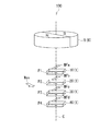
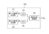
以下、本発明の実施の形態について図面を参照して詳細に説明する。始めに、図1を参照して、本発明の第1の実施の形態に係る角度センサシステムの概略の構成について説明する。本実施の形態に係る角度センサシステム100は、本実施の形態に係る角度センサ1と、磁界発生部5とを備えている。角度センサ1は、特に、磁気式の角度センサである。磁界発生部5は、角度センサ1が検出すべき本来の磁界である検出対象磁界を発生する。
[First Embodiment]
Hereinafter, embodiments of the present invention will be described in detail with reference to the drawings. First, the schematic configuration of the angle sensor system according to the first embodiment of the present invention will be described with reference to FIG. An
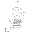
本実施の形態における磁界発生部5は、円柱状の磁石6である。磁石6は、円柱の中心軸を含む仮想の平面を中心として対称に配置されたN極とS極とを有している。この磁石6は、円柱の中心軸を中心として回転する。これにより、磁石6が発生する検出対象磁界の方向は、円柱の中心軸を含む回転中心Cを中心として回転する。
The
角度センサ1は、検出対象の角度と対応関係を有する角度検出値θsを生成するものである。本実施の形態における検出対象の角度は、基準位置における検出対象磁界の方向が基準方向に対してなす角度と対応関係を有する。以下、基準位置における検出対象磁界の方向が基準方向に対してなす角度を回転磁界角度と言い、記号θMで表す。
The
基準位置は、磁石6の一方の端面に平行な仮想の平面(以下、基準平面と言う。)内に位置する。この基準平面内において、磁石6が発生する検出対象磁界の方向は、基準位置を中心として回転する。基準方向は、基準平面内に位置して、基準位置と交差する。以下の説明において、基準位置における検出対象磁界の方向とは、基準平面内に位置する方向を指す。
The reference position is located in a virtual plane (hereinafter referred to as a reference plane) parallel to one end face of the
角度センサ1は、複数の合成磁界情報生成部を備えている。複数の合成磁界情報生成部は、それぞれ互いに異なる複数の検出位置において、検出対象磁界と、それ以外のノイズ磁界との合成磁界を検出し、合成磁界の方向と強度のうちの少なくとも方向の情報を含む複数の合成磁界情報を生成する。複数の検出位置の各々において、検出対象磁界の方向は、検出対象の角度および回転磁界角度θMに応じて変化する。本実施の形態では特に、複数の検出位置は、磁界発生部5からの距離が互いに異なる。複数の検出位置において、検出対象磁界の強度は、互いに異なる。
The
検出位置の数は2以上であればよい。以下、複数の検出位置が、第1の検出位置P1と第2の検出位置P2と第3の検出位置P3と第4の検出位置P4である場合について説明する。この場合、複数の合成磁界情報は、第1の合成磁界情報と第2の合成磁界情報と第3の合成磁界情報と第4の合成磁界情報である。複数の合成磁界情報生成部は、第1の合成磁界情報生成部10と第2の合成磁界情報生成部20と第3の合成磁界情報生成部30と第4の合成磁界情報生成部40である。第1ないし第4の合成磁界情報生成部10,20,30,40は、磁石6の一方の端面に対向するように配置される。
The number of detection positions may be two or more. Hereinafter, a case where the plurality of detection positions are the first detection position P1, the second detection position P2, the third detection position P3, and the fourth detection position P4 will be described. In this case, the plurality of synthesized magnetic field information is first synthesized magnetic field information, second synthesized magnetic field information, third synthesized magnetic field information, and fourth synthesized magnetic field information. The plurality of combined magnetic field information generation units are a first combined magnetic field
第1ないし第4の検出位置P1〜P4は、磁界発生部5を通過する仮想の直線上の互いに異なる位置であってもよい。この仮想の直線は、回転中心Cと一致していてもよいし、一致していなくてもよい。図1には、前者の場合の例を示している。この例では、第1ないし第4の検出位置P1〜P4は、磁界発生部5から遠ざかる方向に、この順に並んでいる。なお、必ずしも、第1ないし第4の検出位置P1〜P4の全てが同一直線上にある必要はない。
The first to fourth detection positions P1 to P4 may be different positions on an imaginary straight line that passes through the magnetic
第1の合成磁界情報生成部10は、第1の検出位置P1において、検出対象磁界とノイズ磁界との合成磁界を検出し、第1の合成磁界情報を生成する。第2の合成磁界情報生成部20は、第2の検出位置P2において、検出対象磁界とノイズ磁界との合成磁界を検出し、第2の合成磁界情報を生成する。第3の合成磁界情報生成部30は、第3の検出位置P3において、検出対象磁界とノイズ磁界との合成磁界を検出し、第3の合成磁界情報を生成する。第4の合成磁界情報生成部40は、第4の検出位置P4において、検出対象磁界とノイズ磁界との合成磁界を検出し、第4の合成磁界情報を生成する。
The first combined magnetic field
以下、第1の検出位置P1における検出対象磁界を特に第1の部分磁界MFaと言い、第2の検出位置P2における検出対象磁界を特に第2の部分磁界MFbと言い、第3の検出位置P3における検出対象磁界を特に第3の部分磁界MFcと言い、第4の検出位置P4における検出対象磁界を特に第4の部分磁界MFdと言う。第1ないし第4の部分磁界MFa〜MFdの方向は、検出対象の角度および回転磁界角度θMに応じて変化する。第1ないし第4の部分磁界MFa〜MFdの強度は、互いに異なる。 Hereinafter, the detection target magnetic field at the first detection position P1 is particularly referred to as a first partial magnetic field MFa, the detection target magnetic field at the second detection position P2 is particularly referred to as a second partial magnetic field MFb, and the third detection position P3. The detection target magnetic field in FIG. 5 is particularly referred to as a third partial magnetic field MFc, and the detection target magnetic field at the fourth detection position P4 is particularly referred to as a fourth partial magnetic field MFd. The directions of the first to fourth partial magnetic fields MFa to MFd change according to the angle of the detection target and the rotating magnetic field angle θM. The strengths of the first to fourth partial magnetic fields MFa to MFd are different from each other.
本実施の形態では、以下のように、複数の合成磁界情報の各々は、合成磁界の方向と強度の情報を含む。第1の合成磁界情報は、第1の検出位置P1における合成磁界の方向と強度の情報を含む。第2の合成磁界情報は、第2の検出位置P2における合成磁界の方向と強度の情報を含む。第3の合成磁界情報は、第3の検出位置P3における合成磁界の方向と強度の情報を含む。第4の合成磁界情報は、第4の検出位置P4における合成磁界の方向と強度の情報を含む。以下、第1の検出位置P1における合成磁界を特に第1の合成磁界MF1と言い、第2の検出位置P2における合成磁界を特に第2の合成磁界MF2と言い、第3の検出位置P3における合成磁界を特に第3の合成磁界MF3と言い、第4の検出位置P4における合成磁界を特に第4の合成磁界MF4と言う。 In the present embodiment, as described below, each of the plurality of combined magnetic field information includes information on the direction and intensity of the combined magnetic field. The first combined magnetic field information includes information on the direction and intensity of the combined magnetic field at the first detection position P1. The second combined magnetic field information includes information on the direction and intensity of the combined magnetic field at the second detection position P2. The third combined magnetic field information includes information on the direction and intensity of the combined magnetic field at the third detection position P3. The fourth combined magnetic field information includes information on the direction and intensity of the combined magnetic field at the fourth detection position P4. Hereinafter, the combined magnetic field at the first detection position P1 is particularly referred to as a first combined magnetic field MF1, and the combined magnetic field at the second detection position P2 is specifically referred to as a second combined magnetic field MF2, and is combined at the third detection position P3. The magnetic field is particularly referred to as a third synthetic magnetic field MF3, and the synthetic magnetic field at the fourth detection position P4 is particularly referred to as a fourth synthetic magnetic field MF4.
第1ないし第4の検出位置P1〜P4におけるノイズ磁界の方向は互いに等しく、第1ないし第4の検出位置P1〜P4におけるノイズ磁界の強度は互いに等しい。以下、ノイズ磁界を記号Mexで表す。ノイズ磁界Mexは、その方向と強度が時間的に一定の磁界であってもよいし、その方向と強度が時間的に周期的に変化する磁界であってもよいし、その方向と強度が時間的にランダムに変化する磁界であってもよい。第1の合成磁界MF1は、第1の部分磁界MFaとノイズ磁界Mexとの合成磁界である。第2の合成磁界MF2は、第2の部分磁界MFbとノイズ磁界Mexとの合成磁界である。第3の合成磁界MF3は、第3の部分磁界MFcとノイズ磁界Mexとの合成磁界である。第4の合成磁界MF4は、第4の部分磁界MFdとノイズ磁界Mexとの合成磁界である。 The directions of the noise magnetic fields at the first to fourth detection positions P1 to P4 are equal to each other, and the strengths of the noise magnetic fields at the first to fourth detection positions P1 to P4 are equal to each other. Hereinafter, the noise magnetic field is represented by the symbol Mex. The noise magnetic field Mex may be a magnetic field whose direction and intensity are constant over time, or a magnetic field whose direction and intensity periodically change over time, and whose direction and intensity are temporal. Alternatively, the magnetic field may change randomly. The first combined magnetic field MF1 is a combined magnetic field of the first partial magnetic field MFa and the noise magnetic field Mex. The second combined magnetic field MF2 is a combined magnetic field of the second partial magnetic field MFb and the noise magnetic field Mex. The third combined magnetic field MF3 is a combined magnetic field of the third partial magnetic field MFc and the noise magnetic field Mex. The fourth combined magnetic field MF4 is a combined magnetic field of the fourth partial magnetic field MFd and the noise magnetic field Mex.
なお、本実施の形態に係る角度センサシステム100の構成は、図1に示した例に限られない。例えば、図1に示したように配置された磁界発生部5と第1ないし第4の合成磁界情報生成部10,20,30,40において、磁界発生部5が固定されて第1ないし第4の合成磁界情報生成部10,20,30,40が回転してもよいし、磁界発生部5と第1ないし第4の合成磁界情報生成部10,20,30,40が互いに反対方向に回転してもよいし、磁界発生部5と第1ないし第4の合成磁界情報生成部10,20,30,40が同じ方向に互いに異なる角速度で回転してもよい。
The configuration of the
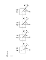
ここで、図1および図2を参照して、本実施の形態における方向と角度の定義について説明する。まず、図1に示した回転中心Cに平行で、図1における下から上に向かう方向をZ方向とする。図2では、Z方向を図2における奥から手前に向かう方向として表している。次に、Z方向に垂直な2方向であって、互いに直交する2つの方向をX方向とY方向とする。図2では、X方向を右側に向かう方向として表し、Y方向を上側に向かう方向として表している。また、X方向とは反対の方向を−X方向とし、Y方向とは反対の方向を−Y方向とする。 Here, with reference to FIG. 1 and FIG. 2, the definition of the direction and angle in this Embodiment is demonstrated. First, the direction parallel to the rotation center C shown in FIG. 1 and going from bottom to top in FIG. In FIG. 2, the Z direction is represented as a direction from the back to the front in FIG. Next, two directions perpendicular to the Z direction and orthogonal to each other are defined as an X direction and a Y direction. In FIG. 2, the X direction is represented as a direction toward the right side, and the Y direction is represented as a direction toward the upper side. In addition, a direction opposite to the X direction is defined as -X direction, and a direction opposite to the Y direction is defined as -Y direction.
回転磁界角度θMは、基準方向DRを基準にして表される。本実施の形態では、X方向を基準方向DRとする。 The rotating magnetic field angle θM is expressed with reference to the reference direction DR. In the present embodiment, the X direction is the reference direction DR.
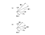
第1ないし第4の合成磁界MF1〜MF4の方向は、いずれも、図2において反時計回り方向に回転するものとする。図2に示したように、第1の合成磁界MF1の方向が基準方向DRに対してなす角度を記号θ1で表し、第2の合成磁界MF2の方向が基準方向DRに対してなす角度を記号θ2で表し、第3の合成磁界MF3の方向が基準方向DRに対してなす角度を記号θ3で表し、第4の合成磁界MF4の方向が基準方向DRに対してなす角度を記号θ4で表す。角度θ1〜θ4は、基準方向DRから反時計回り方向に見たときに正の値で表し、基準方向DRから時計回り方向に見たときに負の値で表す。 The directions of the first to fourth synthetic magnetic fields MF1 to MF4 are all assumed to rotate counterclockwise in FIG. As shown in FIG. 2 represents the angle formed with respect to the first resultant magnetic field MF1 directions reference direction DR by the symbol theta 1, the angle at which the direction of the second resultant magnetic field MF2 forms with respect to a reference direction DR expressed by the symbol theta 2, represents the angle that the direction of the third combined magnetic field MF3 forms with respect to a reference direction DR by symbol theta 3, angle symbols forming direction of the fourth composite magnetic field MF4 is with respect to the reference direction DR theta 4 The angles θ 1 to θ 4 are represented by positive values when viewed counterclockwise from the reference direction DR, and are represented by negative values when viewed clockwise from the reference direction DR.
第1の合成磁界MF1の主成分は、第1の部分磁界MFaである。第2の合成磁界MF2の主成分は、第2の部分磁界MFbである。第3の合成磁界MF3の主成分は、第3の部分磁界MFcである。第4の合成磁界MF4の主成分は、第4の部分磁界MFdである。第1ないし第4の部分磁界MFa〜MFdの方向は、同じ方向になる。また、第1ないし第4の部分磁界MFa〜MFdが基準方向DRに対してなすそれぞれの角度は、互いに等しくなる。 The main component of the first synthetic magnetic field MF1 is the first partial magnetic field MFa. The main component of the second synthetic magnetic field MF2 is the second partial magnetic field MFb. The main component of the third synthetic magnetic field MF3 is the third partial magnetic field MFc. The main component of the fourth synthetic magnetic field MF4 is the fourth partial magnetic field MFd. The directions of the first to fourth partial magnetic fields MFa to MFd are the same direction. In addition, the angles formed by the first to fourth partial magnetic fields MFa to MFd with respect to the reference direction DR are equal to each other.
本実施の形態では、第1ないし第4の部分磁界MFa〜MFdの方向は、基準位置における検出対象磁界の方向に一致するものとする。また、第1ないし第4の部分磁界MFa〜MFdが基準方向DRに対してなすそれぞれの角度は、回転磁界角度θMと等しいものとする。これらの角度の正負の定義は、角度θ1〜θ4と同様である。 In the present embodiment, the directions of the first to fourth partial magnetic fields MFa to MFd are assumed to coincide with the direction of the detection target magnetic field at the reference position. In addition, each angle formed by the first to fourth partial magnetic fields MFa to MFd with respect to the reference direction DR is equal to the rotating magnetic field angle θM. The definition of the positive and negative of these angles is the same as the angles θ 1 to θ 4 .
基準位置は、上記の第1ないし第4の部分磁界MFa〜MFdと基準位置における検出対象磁界との関係を満たす限り、第1ないし第4の検出位置P1〜P4のいずれかと一致していてもよいし、これらの位置とは異なる、回転中心C上の位置であってもよい。 The reference position may coincide with any of the first to fourth detection positions P1 to P4 as long as the relationship between the first to fourth partial magnetic fields MFa to MFd and the detection target magnetic field at the reference position is satisfied. It may be a position on the rotation center C that is different from these positions.
後で詳しく説明するが、合成磁界情報は、合成磁界の、互いに異なる方向の2つの成分の強度に基づいて生成される。本実施の形態では特に、この2つの成分は、合成磁界の、互いに直交する方向の2つの成分である。本実施の形態では、この2つの成分の基準となる2つの方向を、X方向とY方向とする。 As will be described in detail later, the combined magnetic field information is generated based on the intensities of two components of the combined magnetic field in different directions. Particularly in the present embodiment, these two components are two components of the resultant magnetic field in directions orthogonal to each other. In the present embodiment, the two directions serving as the reference for these two components are the X direction and the Y direction.
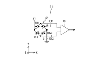
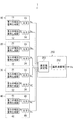
次に、図3を参照して、角度センサ1の構成について詳しく説明する。図3は、角度センサ1の構成を示す機能ブロック図である。前述の通り、角度センサ1は、複数の合成磁界情報生成部を備えている。複数の合成磁界情報生成部の各々は、合成磁界の、互いに異なる方向の2つの成分の強度を表す2つの検出信号を生成する2つの検出信号生成部を含んでいる。合成磁界情報は、2つの検出信号に基づいて生成される。2つの検出信号生成部の各々は、少なくとも1つの磁気検出素子を含んでいる。少なくとも1つの磁気検出素子は、少なくとも1つの磁気抵抗効果素子を含んでいてもよい。磁気抵抗効果素子は、GMR(巨大磁気抵抗効果)素子でもよいし、TMR(トンネル磁気抵抗効果)素子でもよいし、AMR(異方性磁気抵抗効果)素子でもよい。また、少なくとも1つの磁気検出素子は、ホール素子等、磁気抵抗効果素子以外の磁界を検出する素子を、少なくとも1つ含んでいてもよい。
Next, the configuration of the
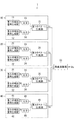
本実施の形態では、複数の合成磁界情報生成部は、第1の合成磁界情報生成部10と第2の合成磁界情報生成部20と第3の合成磁界情報生成部30と第4の合成磁界情報生成部40である。第1の合成磁界情報生成部10は、第1の検出信号生成部11と第2の検出信号生成部12とを含んでいる。第1の検出信号生成部11は、第1の合成磁界MF1の、X方向の成分の強度を表す第1の検出信号S1を生成する。第2の検出信号生成部12は、第1の合成磁界MF1の、Y方向の成分の強度を表す第2の検出信号S2を生成する。
In the present embodiment, the plurality of synthesized magnetic field information generating units includes the first synthesized magnetic field
第1の合成磁界情報は、第1および第2の検出信号S1,S2に基づいて生成される。本実施の形態では、第1の合成磁界情報は、第1の合成磁界MF1の方向と強度の情報を含むベクトルで表わされる。第1の合成磁界情報生成部10は、更に、アナログ−デジタル変換器(以下、A/D変換器と記す。)13,14と、第1のベクトル生成部15とを含んでいる。A/D変換器13,14は、それぞれ、第1および第2の検出信号S1,S2をデジタル信号に変換する。第1のベクトル生成部15は、それぞれA/D変換器13,14によってデジタル信号に変換された第1および第2の検出信号S1,S2を用いて、第1の合成磁界情報を表すベクトルY1を生成する。第1のベクトル生成部15は、例えば、特定用途向け集積回路(ASIC)によって実現することができる。
The first combined magnetic field information is generated based on the first and second detection signals S1 and S2. In the present embodiment, the first combined magnetic field information is represented by a vector including information on the direction and intensity of the first combined magnetic field MF1. The first synthetic magnetic field
第2の合成磁界情報生成部20は、第3の検出信号生成部21と第4の検出信号生成部22とを含んでいる。第3の検出信号生成部21は、第2の合成磁界MF2の、X方向の成分の強度を表す第3の検出信号S3を生成する。第4の検出信号生成部22は、第2の合成磁界MF2の、Y方向の成分の強度を表す第4の検出信号S4を生成する。
The second synthetic magnetic field
第2の合成磁界情報は、第3および第4の検出信号S3,S4に基づいて生成される。本実施の形態では、第2の合成磁界情報は、第2の合成磁界MF2の方向と強度の情報を含むベクトルで表わされる。第2の合成磁界情報生成部20は、更に、A/D変換器23,24と、第2のベクトル生成部25とを含んでいる。A/D変換器23,24は、それぞれ、第3および第4の検出信号S3,S4をデジタル信号に変換する。第2のベクトル生成部25は、それぞれA/D変換器23,24によってデジタル信号に変換された第3および第4の検出信号S3,S4を用いて、第2の合成磁界情報を表すベクトルY2を生成する。第2のベクトル生成部25は、例えば、ASICによって実現することができる。
The second synthesized magnetic field information is generated based on the third and fourth detection signals S3 and S4. In the present embodiment, the second combined magnetic field information is represented by a vector including information on the direction and intensity of the second combined magnetic field MF2. The second synthesized magnetic field
第3の合成磁界情報生成部30は、第5の検出信号生成部31と第6の検出信号生成部32とを含んでいる。第5の検出信号生成部31は、第3の合成磁界MF3の、X方向の成分の強度を表す第5の検出信号S5を生成する。第6の検出信号生成部32は、第3の合成磁界MF3の、Y方向の成分の強度を表す第6の検出信号S6を生成する。
The third synthetic magnetic field
第3の合成磁界情報は、第5および第6の検出信号S5,S6に基づいて生成される。本実施の形態では、第3の合成磁界情報は、第3の合成磁界MF3の方向と強度の情報を含むベクトルで表わされる。第3の合成磁界情報生成部30は、更に、A/D変換器33,34と、第3のベクトル生成部35とを含んでいる。A/D変換器33,34は、それぞれ、第5および第6の検出信号S5,S6をデジタル信号に変換する。第3のベクトル生成部35は、それぞれA/D変換器33,34によってデジタル信号に変換された第5および第6の検出信号S5,S6を用いて、第3の合成磁界情報を表すベクトルY3を生成する。第3のベクトル生成部35は、例えば、ASICによって実現することができる。
The third combined magnetic field information is generated based on the fifth and sixth detection signals S5 and S6. In the present embodiment, the third combined magnetic field information is represented by a vector including information on the direction and intensity of the third combined magnetic field MF3. The third synthesized magnetic field
第4の合成磁界情報生成部40は、第7の検出信号生成部41と第8の検出信号生成部42とを含んでいる。第7の検出信号生成部41は、第4の合成磁界MF4の、X方向の成分の強度を表す第7の検出信号S7を生成する。第8の検出信号生成部42は、第4の合成磁界MF4の、Y方向の成分の強度を表す第8の検出信号S8を生成する。
The fourth synthetic magnetic field
第4の合成磁界情報は、第7および第8の検出信号S7,S8に基づいて生成される。本実施の形態では、第4の合成磁界情報は、第4の合成磁界MF4の方向と強度の情報を含むベクトルで表わされる。第4の合成磁界情報生成部40は、更に、A/D変換器43,44と、第4のベクトル生成部45とを含んでいる。A/D変換器43,44は、それぞれ、第7および第8の検出信号S7,S8をデジタル信号に変換する。第4のベクトル生成部45は、それぞれA/D変換器43,44によってデジタル信号に変換された第7および第8の検出信号S7,S8を用いて、第4の合成磁界情報を表すベクトルY4を生成する。第4のベクトル生成部45は、例えば、ASICによって実現することができる。
The fourth synthesized magnetic field information is generated based on the seventh and eighth detection signals S7 and S8. In the present embodiment, the fourth combined magnetic field information is represented by a vector including information on the direction and intensity of the fourth combined magnetic field MF4. The fourth synthetic magnetic field
検出対象磁界の方向が所定の周期で回転すると、回転磁界角度θMは所定の周期で変化する。この場合、第1ないし第8の検出信号S1〜S8は、いずれも、上記所定の周期と等しい信号周期で周期的に変化する。第2の検出信号S2の位相は、第1の検出信号S1の位相に対して、信号周期の1/4の奇数倍だけ異なっている。第3、第5および第7の検出信号S3,S5,S7の位相は、それぞれ、第1の検出信号S1の位相と一致している。第4、第6および第8の検出信号S4,S6,S8の位相は、それぞれ、第2の検出信号S2の位相と一致している。なお、磁気検出素子の作製の精度等の観点から、これらの信号の位相の関係は、上記の関係からわずかにずれていてもよい。 When the direction of the detection target magnetic field rotates at a predetermined cycle, the rotating magnetic field angle θM changes at a predetermined cycle. In this case, each of the first to eighth detection signals S1 to S8 periodically changes with a signal period equal to the predetermined period. The phase of the second detection signal S2 differs from the phase of the first detection signal S1 by an odd multiple of 1/4 of the signal period. The phases of the third, fifth, and seventh detection signals S3, S5, and S7 respectively match the phase of the first detection signal S1. The phases of the fourth, sixth, and eighth detection signals S4, S6, and S8 respectively match the phase of the second detection signal S2. Note that the phase relationship of these signals may be slightly deviated from the above relationship from the viewpoint of the accuracy of manufacturing the magnetic detection element.
角度センサ1は、更に、複数の合成磁界情報に基づいて、最小二乗法を用いて、角度検出値θsを生成する角度演算部50を備えている。前述のように、複数の検出位置は、互いに異なる。そのため、複数の合成磁界情報に与えるノイズ磁界Mexの相対的な影響に違いが生じる。その結果、複数の合成磁界情報間には、ノイズ磁界Mexに依存した違いが生じ得る。この性質を利用すると、ノイズ磁界Mexの影響が排除された検出対象の角度を推定することが可能である。角度演算部50は、この性質を利用して、角度検出値θsを生成する。角度演算部50は、例えば、ASICまたはマイクロコンピュータによって実現することができる。角度演算部50の構成と角度検出値θsの生成方法については、後で説明する。
The
次に、第1ないし第8の検出信号生成部11,12,21,22,31,32,41,42の構成について説明する。図5は、第1の検出信号生成部11の具体的な構成の一例を示している。この例では、第1の検出信号生成部11は、ホイートストンブリッジ回路17と、差分検出器18とを有している。ホイートストンブリッジ回路17は、電源ポートV1と、グランドポートG1と、2つの出力ポートE11,E12と、直列に接続された第1の対の磁気検出素子R11,R12と、直列に接続された第2の対の磁気検出素子R13,R14とを含んでいる。磁気検出素子R11,R13の各一端は、電源ポートV1に接続されている。磁気検出素子R11の他端は、磁気検出素子R12の一端と出力ポートE11に接続されている。磁気検出素子R13の他端は、磁気検出素子R14の一端と出力ポートE12に接続されている。磁気検出素子R12,R14の各他端は、グランドポートG1に接続されている。電源ポートV1には、所定の大きさの電源電圧が印加される。グランドポートG1はグランドに接続される。
Next, the configuration of the first to eighth detection
第3、第5および第7の検出信号生成部21,31,41の各々の構成は、第1の検出信号生成部11の構成と同じである。そのため、以下の説明では、第3、第5および第7の検出信号生成部21,31,41の構成要素について、第1の検出信号生成部11の構成要素と同じ符号を用いる。
The configuration of each of the third, fifth and seventh detection
図6は、第2の検出信号生成部12の具体的な構成の一例を示している。この例では、第2の検出信号生成部12は、ホイートストンブリッジ回路27と、差分検出器28とを有している。ホイートストンブリッジ回路27は、電源ポートV2と、グランドポートG2と、2つの出力ポートE21,E22と、直列に接続された第1の対の磁気検出素子R21,R22と、直列に接続された第2の対の磁気検出素子R23,R24とを含んでいる。磁気検出素子R21,R23の各一端は、電源ポートV2に接続されている。磁気検出素子R21の他端は、磁気検出素子R22の一端と出力ポートE21に接続されている。磁気検出素子R23の他端は、磁気検出素子R24の一端と出力ポートE22に接続されている。磁気検出素子R22,R24の各他端は、グランドポートG2に接続されている。電源ポートV2には、所定の大きさの電源電圧が印加される。グランドポートG2はグランドに接続される。
FIG. 6 shows an example of a specific configuration of the second detection
第4、第6および第8の検出信号生成部22,32,42の各々の構成は、第2の検出信号生成部12の構成と同じである。そのため、以下の説明では、第4、第6および第8の検出信号生成部22,32,42の構成要素について、第2の検出信号生成部12の構成要素と同じ符号を用いる。
The configuration of each of the fourth, sixth, and eighth detection
本実施の形態では、磁気検出素子R11〜R14,R21〜R24の各々は、直列に接続された複数の磁気抵抗効果素子(MR素子)を含んでいる。複数のMR素子の各々は、例えばスピンバルブ型のMR素子である。このスピンバルブ型のMR素子は、磁化方向が固定された磁化固定層と、検出対象磁界の方向に応じて磁化の方向が変化する磁性層である自由層と、磁化固定層と自由層の間に配置された非磁性層とを有している。スピンバルブ型のMR素子は、TMR素子でもよいし、GMR素子でもよい。TMR素子では、非磁性層はトンネルバリア層である。GMR素子では、非磁性層は非磁性導電層である。スピンバルブ型のMR素子では、自由層の磁化の方向が磁化固定層の磁化の方向に対してなす角度に応じて抵抗値が変化し、この角度が0°のときに抵抗値は最小値となり、角度が180°のときに抵抗値は最大値となる。図5および図6において、塗りつぶした矢印は、MR素子における磁化固定層の磁化の方向を表し、白抜きの矢印は、MR素子における自由層の磁化の方向を表している。 In the present embodiment, each of the magnetic detection elements R11 to R14, R21 to R24 includes a plurality of magnetoresistance effect elements (MR elements) connected in series. Each of the plurality of MR elements is, for example, a spin valve type MR element. This spin-valve MR element includes a magnetization fixed layer whose magnetization direction is fixed, a free layer that is a magnetic layer whose magnetization direction changes according to the direction of a magnetic field to be detected, and a magnetization layer between the magnetization fixed layer and the free layer. And a nonmagnetic layer. The spin valve MR element may be a TMR element or a GMR element. In the TMR element, the nonmagnetic layer is a tunnel barrier layer. In the GMR element, the nonmagnetic layer is a nonmagnetic conductive layer. In a spin-valve MR element, the resistance value changes according to the angle formed by the magnetization direction of the free layer with respect to the magnetization direction of the magnetization fixed layer, and the resistance value becomes the minimum value when this angle is 0 °. When the angle is 180 °, the resistance value becomes the maximum value. In FIGS. 5 and 6, solid arrows indicate the direction of magnetization of the magnetization fixed layer in the MR element, and white arrows indicate the direction of magnetization of the free layer in the MR element.
第1の検出信号生成部11では、磁気検出素子R11,R14に含まれる複数のMR素子における磁化固定層の磁化の方向はX方向であり、磁気検出素子R12,R13に含まれる複数のMR素子における磁化固定層の磁化の方向は−X方向である。この場合、第1の合成磁界MF1のX方向の成分の強度に応じて、出力ポートE11,E12の電位差が変化する。差分検出器18は、出力ポートE11,E12の電位差に対応する信号を第1の検出信号S1として出力する。従って、第1の検出信号生成部11は、第1の合成磁界MF1のX方向の成分の強度を検出して、その強度を表す第1の検出信号S1を生成する。
In the first detection
第2の検出信号生成部12では、磁気検出素子R21,R24に含まれる複数のMR素子における磁化固定層の磁化の方向はY方向であり、磁気検出素子R22,R23に含まれる複数のMR素子における磁化固定層の磁化の方向は−Y方向である。この場合、第1の合成磁界MF1のY方向の成分の強度に応じて、出力ポートE21,E22の電位差が変化する。差分検出器28は、出力ポートE21,E22の電位差に対応する信号を第2の検出信号S2として出力する。従って、第2の検出信号生成部12は、第1の合成磁界MF1のY方向の成分の強度を検出して、その強度を表す第2の検出信号S2を生成する。
In the second detection
第3の検出信号生成部21では、第2の合成磁界MF2のX方向の成分の強度に応じて、出力ポートE11,E12の電位差が変化する。差分検出器18は、出力ポートE11,E12の電位差に対応する信号を第3の検出信号S3として出力する。従って、第3の検出信号生成部21は、第2の合成磁界MF2のX方向の成分の強度を検出して、その強度を表す第3の検出信号S3を生成する。
In the third detection
第4の検出信号生成部22では、第2の合成磁界MF2のY方向の成分の強度に応じて、出力ポートE21,E22の電位差が変化する。差分検出器28は、出力ポートE21,E22の電位差に対応する信号を第4の検出信号S4として出力する。従って、第4の検出信号生成部22は、第2の合成磁界MF2のY方向の成分の強度を検出して、その強度を表す第4の検出信号S4を生成する。
In the fourth detection
第5の検出信号生成部31では、第3の合成磁界MF3のX方向の成分の強度に応じて、出力ポートE11,E12の電位差が変化する。差分検出器18は、出力ポートE11,E12の電位差に対応する信号を第3の検出信号S3として出力する。従って、第5の検出信号生成部31は、第3の合成磁界MF3のX方向の成分の強度を検出して、その強度を表す第5の検出信号S5を生成する。
In the fifth detection
第6の検出信号生成部32では、第3の合成磁界MF3のY方向の成分の強度に応じて、出力ポートE21,E22の電位差が変化する。差分検出器28は、出力ポートE21,E22の電位差に対応する信号を第6の検出信号S6として出力する。従って、第6の検出信号生成部32は、第3の合成磁界MF3のY方向の成分の強度を検出して、その強度を表す第6の検出信号S6を生成する。
In the sixth detection
第7の検出信号生成部41では、第4の合成磁界MF4のX方向の成分の強度に応じて、出力ポートE11,E12の電位差が変化する。差分検出器18は、出力ポートE11,E12の電位差に対応する信号を第7の検出信号S7として出力する。従って、第7の検出信号生成部41は、第4の合成磁界MF4のX方向の成分の強度を検出して、その強度を表す第7の検出信号S7を生成する。
In the seventh detection
第8の検出信号生成部42では、第4の合成磁界MF4のY方向の成分の強度に応じて、出力ポートE21,E22の電位差が変化する。差分検出器28は、出力ポートE21,E22の電位差に対応する信号を第8の検出信号S8として出力する。従って、第8の検出信号生成部42は、第4の合成磁界MF4のY方向の成分の強度を検出して、その強度を表す第8の検出信号S8を生成する。
In the eighth detection
なお、検出信号生成部11,12,21,22,31,32,41,42内の複数のMR素子における磁化固定層の磁化の方向は、MR素子の作製の精度等の観点から、上述の方向からわずかにずれていてもよい。
Note that the magnetization direction of the magnetization fixed layer in the plurality of MR elements in the detection
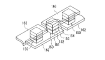
ここで、図7を参照して、磁気検出素子の構成の一例について説明する。図7は、図5および図6に示した検出信号生成部11,12における1つの磁気検出素子の一部を示す斜視図である。この例では、1つの磁気検出素子は、複数の下部電極162と、複数のMR素子150と、複数の上部電極163とを有している。複数の下部電極162は図示しない基板上に配置されている。個々の下部電極162は細長い形状を有している。下部電極162の長手方向に隣接する2つの下部電極162の間には、間隙が形成されている。図7に示したように、下部電極162の上面上において、長手方向の両端の近傍に、それぞれMR素子150が配置されている。MR素子150は、下部電極162側から順に積層された自由層151、非磁性層152、磁化固定層153および反強磁性層154を含んでいる。自由層151は、下部電極162に電気的に接続されている。反強磁性層154は、反強磁性材料よりなり、磁化固定層153との間で交換結合を生じさせて、磁化固定層153の磁化の方向を固定する。複数の上部電極163は、複数のMR素子150の上に配置されている。個々の上部電極163は細長い形状を有し、下部電極162の長手方向に隣接する2つの下部電極162上に配置されて隣接する2つのMR素子150の反強磁性層154同士を電気的に接続する。このような構成により、図7に示した磁気検出素子は、複数の下部電極162と複数の上部電極163とによって直列に接続された複数のMR素子150を有している。なお、MR素子150における層151〜154の配置は、図7に示した配置とは上下が反対でもよい。
Here, an example of the configuration of the magnetic detection element will be described with reference to FIG. FIG. 7 is a perspective view illustrating a part of one magnetic detection element in the detection
次に、第1ないし第4の合成磁界情報の生成方法について説明する。第1の合成磁界情報生成部10の第1のベクトル生成部15は、第1の合成磁界情報を表すベクトルY1を生成する。第1のベクトル生成部15は、それぞれA/D変換器13,14によってデジタル信号に変換された第1および第2の検出信号S1,S2に基づいて、ベクトルY1の方向D1と大きさMa1を求める。方向D1は、第1の合成磁界MF1の方向の情報に対応する。本実施の形態では、方向D1を、第1の合成磁界MF1の方向が基準方向DRに対してなす角度θ1(図2参照)を用いて表す。大きさMa1は、第1の合成磁界MF1の強度の情報に対応する。
Next, a method for generating the first to fourth synthetic magnetic field information will be described. The first
第2の合成磁界情報生成部20の第2のベクトル生成部25は、第2の合成磁界情報を表すベクトルY2を生成する。第2のベクトル生成部25は、それぞれA/D変換器23,24によってデジタル信号に変換された第3および第4の検出信号S3,S4に基づいて、ベクトルY2の方向D2と大きさMa2を求める。方向D2は、第2の合成磁界MF2の方向の情報に対応する。本実施の形態では、方向D2を、第2の合成磁界MF2の方向が基準方向DRに対してなす角度θ2(図2参照)を用いて表す。大きさMa2は、第2の合成磁界MF2の強度の情報に対応する。
The second
第3の合成磁界情報生成部30の第3のベクトル生成部35は、第3の合成磁界情報を表すベクトルY3を生成する。第3のベクトル生成部35は、それぞれA/D変換器33,34によってデジタル信号に変換された第5および第6の検出信号S5,S6に基づいて、ベクトルY3の方向D3と大きさMa3を求める。方向D3は、第3の合成磁界MF3の方向の情報に対応する。本実施の形態では、方向D3を、第3の合成磁界MF3の方向が基準方向DRに対してなす角度θ3(図2参照)を用いて表す。大きさMa3は、第3の合成磁界MF3の強度の情報に対応する。
The third
第4の合成磁界情報生成部40の第4のベクトル生成部45は、第4の合成磁界情報を表すベクトルY4を生成する。第4のベクトル生成部45は、それぞれA/D変換器43,44によってデジタル信号に変換された第7および第8の検出信号S7,S8に基づいて、ベクトルY4の方向D4と大きさMa4を求める。方向D4は、第4の合成磁界MF4の方向の情報に対応する。本実施の形態では、方向D4を、第4の合成磁界MF4の方向が基準方向DRに対してなす角度θ4(図2参照)を用いて表す。大きさMa4は、第4の合成磁界MF4の強度の情報に対応する。
The fourth
以下、ベクトルY1〜Y4の生成方法について具体的に説明する。第1のベクトル生成部15は、第1の検出信号S1と第2の検出信号S2の比のアークタンジェントを計算してベクトルY1の方向D1すなわち角度θ1を求める。具体的には、第1のベクトル生成部15は、下記の式(1)によって、角度θ1を求める。なお、“atan”は、アークタンジェントを表す。
Hereinafter, a method for generating the vectors Y1 to Y4 will be specifically described. The first
θ1=atan(S2/S1) …(1) θ 1 = atan (S2 / S1) (1)
θ1が0°以上360°未満の範囲内では、式(1)におけるθ1の解には、180°異なる2つの値がある。しかし、S1,S2の正負の組み合わせにより、θ1の真の値が、式(1)におけるθ1の2つの解のいずれであるかを判別することができる。第1のベクトル生成部15は、式(1)と、上記のS1,S2の正負の組み合わせの判定により、0°以上360°未満の範囲内でθ1を求める。
Within the range of θ 1 between 0 ° and less than 360 °, the solution of θ 1 in equation (1) has two values that differ by 180 °. However, it is possible to determine which of the two solutions of θ 1 in Equation (1) is the true value of θ 1 by the combination of S1 and S2. The first
また、第1のベクトル生成部15は、第1の検出信号S1の二乗と第2の検出信号S2の二乗との和S12+S22を計算してベクトルY1の大きさMa1を求める。前述のように、第1の検出信号S1は第1の合成磁界MF1のX方向の強度を表し、第2の検出信号S2は第1の合成磁界MF1のY方向の強度を表している。従って、S12+S22は、第1の合成磁界MF1の強度と対応関係を有するパラメータである。
The first
第2のベクトル生成部25は、第3の検出信号S3と第4の検出信号S4の比のアークタンジェントを計算してベクトルY2の方向D2すなわち角度θ2を求める。具体的には、第2のベクトル生成部25は、角度θ1と同様に、下記の式(2)によって、0°以上360°未満の範囲内で角度θ2を求める。
The second
θ2=atan(S4/S3) …(2) θ 2 = atan (S4 / S3) (2)
また、第2のベクトル生成部25は、第3の検出信号S3の二乗と第4の検出信号S4の二乗との和S32+S42を計算してベクトルY2の大きさMa2を求める。前述のように、第3の検出信号S3は第2の合成磁界MF2のX方向の強度を表し、第4の検出信号S4は第2の合成磁界MF2のY方向の強度を表している。従って、S32+S42は、第2の合成磁界MF2の強度と対応関係を有するパラメータである。
The second
第3のベクトル生成部35は、第5の検出信号S5と第6の検出信号S6の比のアークタンジェントを計算してベクトルY3の方向D3すなわち角度θ3を求める。具体的には、第3のベクトル生成部35は、角度θ1と同様に、下記の式(3)によって、0°以上360°未満の範囲内で角度θ3を求める。
The third
θ3=atan(S6/S5) …(3) θ 3 = atan (S6 / S5) (3)
また、第3のベクトル生成部35は、第5の検出信号S5の二乗と第6の検出信号S6の二乗との和S52+S62を計算してベクトルY3の大きさMa3を求める。前述のように、第5の検出信号S5は第3の合成磁界MF3のX方向の強度を表し、第6の検出信号S6は第3の合成磁界MF3のY方向の強度を表している。従って、S52+S62は、第3の合成磁界MF3の強度と対応関係を有するパラメータである。
The
第4のベクトル生成部45は、第7の検出信号S7と第8の検出信号S8の比のアークタンジェントを計算してベクトルY4の方向D4すなわち角度θ4を求める。具体的には、第4のベクトル生成部45は、角度θ1と同様に、下記の式(4)によって、0°以上360°未満の範囲内で角度θ4を求める。
The
θ4=atan(S8/S7) …(4) θ 4 = atan (S8 / S7) (4)
また、第4のベクトル生成部45は、第7の検出信号S7の二乗と第8の検出信号S8の二乗との和S72+S82を計算してベクトルY4の大きさMa4を求める。前述のように、第7の検出信号S7は第4の合成磁界MF4のX方向の強度を表し、第8の検出信号S8は第4の合成磁界MF4のY方向の強度を表している。従って、S72+S82は、第4の合成磁界MF4の強度と対応関係を有するパラメータである。
The
大きさMa1,Ma2,Ma3,Ma4は、それぞれ、S12+S22、S32+S42、S52+S62、S72+S82そのものであってもよい。あるいは、大きさMa1,Ma2,Ma3,Ma4は、それぞれ、S12+S22、S32+S42、S52+S62、S72+S82から求めた合成磁界MF1,MF2,MF3,MF4の強度であってもよい。あるいは、ベクトル生成部15,25,35,45は、それぞれ、S12+S22、S32+S42、S52+S62、S72+S82以外の、合成磁界MF1,MF2,MF3,MF4の強度と対応関係を有するパラメータの値を求めて、これらのパラメータの値に基づいて大きさMa1,Ma2,Ma3,Ma4を求めてもよい。
The magnitudes Ma 1 , Ma 2 , Ma 3 and Ma 4 may be S1 2 + S2 2 , S3 2 + S4 2 , S5 2 + S6 2 , and S7 2 + S8 2, respectively . Alternatively, the magnitudes Ma 1 , Ma 2 , Ma 3 , and Ma 4 are respectively the combined magnetic fields MF1, MF2, MF3, and MF4 obtained from S1 2 + S2 2 , S3 2 + S4 2 , S5 2 + S6 2 , and S7 2 + S8 2 . May be the strength. Alternatively, the
次に、角度演算部50の構成と角度検出値θsの生成方法について説明する。始めに、本実施の形態における角度検出値θsの生成方法について、概念的に説明する。本実施の形態では、角度演算部50は、最小二乗法を用いて角度検出値θsを生成する。より詳しく説明すると、角度演算部50は、複数の合成磁界情報と複数の推定合成磁界情報の対応するもの同士の差の二乗和が最小になるように第1の推定値Mおよび第2の推定値Eを決定する。第1の推定値Mは、角度検出値θsに対応する方向の情報と所定の位置における検出対象磁界の強度に対応する大きさの情報とを含む。第2の推定値Eは、ノイズ磁界Mexの方向に対応する方向の情報とノイズ磁界Mexの強度に対応する大きさの情報とを含む。
Next, a configuration of the
複数の推定合成磁界情報は、それぞれ複数の合成磁界情報の推定情報である。複数の推定合成磁界情報は、第1および第2の推定値M,Eに基づいて生成される。本実施の形態では、複数の推定合成磁界情報を、下記の式(5)のようにモデル化する。 The plurality of estimated synthesized magnetic field information is estimated information of the plurality of synthesized magnetic field information. A plurality of estimated synthesized magnetic field information is generated based on the first and second estimated values M and E. In the present embodiment, a plurality of estimated synthesized magnetic field information is modeled as in the following equation (5).
z=Hx …(5) z = Hx (5)
式(5)におけるzは、求めるべき第1および第2の推定値M,Eに基づいて生成された複数の推定合成磁界情報と対応関係を有するm個の要素を含むm次元列ベクトルである。なお、mは、複数の推定合成磁界情報の数を表す整数であり、これは、複数の合成磁界情報の数と同じである。式(5)におけるHは、複数の検出位置における検出対象磁界とノイズ磁界Mexの態様に応じて規定されるm行2列の行列である。式(5)におけるxは、第1の推定値Mと第2の推定値Eを要素とする2次元列ベクトルである。 Z in Equation (5) is an m-dimensional column vector including m elements having a correspondence relationship with a plurality of estimated synthesized magnetic field information generated based on the first and second estimated values M and E to be obtained. . Note that m is an integer representing the number of pieces of estimated combined magnetic field information, which is the same as the number of pieces of combined magnetic field information. H in Expression (5) is an m-row / 2-column matrix defined according to the detection target magnetic field and the noise magnetic field Mex at a plurality of detection positions. In Expression (5), x is a two-dimensional column vector having the first estimated value M and the second estimated value E as elements.
本実施の形態では、列ベクトルxを決定することにより、第1および第2の推定値M,Eを決定する。ここで、複数の合成磁界情報と対応関係を有するm個の要素を含むm次元列ベクトルを記号yで表す。列ベクトルxは、列ベクトルyのm個の要素と列ベクトルzのm個の要素の対応するもの同士の差の二乗和が最小になるように決定される。これは、具体的には、列ベクトルxを決定するための最小二乗コスト関数Fを定義して、この関数Fの値を最小にする列ベクトルxを求めることによって実現される。関数Fは、下記の式(6)によって定義される。 In the present embodiment, the first and second estimated values M and E are determined by determining the column vector x. Here, an m-dimensional column vector including m elements having a correspondence relationship with a plurality of synthesized magnetic field information is represented by a symbol y. The column vector x is determined so that the sum of squares of the difference between the corresponding elements of the m elements of the column vector y and the m elements of the column vector z is minimized. Specifically, this is realized by defining a least square cost function F for determining the column vector x and obtaining the column vector x that minimizes the value of the function F. The function F is defined by the following equation (6).
F=||y−z||2
=||y−Hx||2
=(y−Hx)T(y−Hx)
=yTy−xTHTy−yTHx+xTHTHx …(6)
F = || yz || 2
= || y-Hx || 2
= (Y-Hx) T (y-Hx)
= Y T y-x T H T y-y T Hx + x T H T Hx ... (6)
式(6)をxによって偏微分すると、下記の式(7)が得られる。 If the equation (6) is partially differentiated by x, the following equation (7) is obtained.
∂F/∂x=2(−HTy+HTHx) …(7) ∂F / ∂x = 2 (−H T y + H T Hx) (7)
関数Fの値を最小にするxは、∂F/∂x=0を満たす。従って、関数Fの値を最小にするxは、下記の式(8)によって表される。 X that minimizes the value of the function F satisfies ∂F / ∂x = 0. Therefore, x that minimizes the value of the function F is expressed by the following equation (8).
x=(HTH)-1HTy …(8) x = (H T H) -1 H T y ... (8)
本実施の形態では、角度演算部50は、式(8)によって算出された列ベクトルxの2つの要素の一方である第1の推定値Mに基づいて、角度検出値θsを決定する。
In the present embodiment, the
なお、前述のように、列ベクトルyは、複数の合成磁界情報と対応関係を有する複数の要素を含み、列ベクトルzは、複数の推定合成磁界情報と対応関係を有する複数の要素を含む。従って、式(6)〜(8)を参照して説明した列ベクトルxの決定方法は、複数の合成磁界情報と複数の推定合成磁界情報の対応するもの同士の差の二乗和が最小になるように、第1および第2の推定値M,Eを決定する方法と言える。 As described above, the column vector y includes a plurality of elements having a correspondence with a plurality of synthesized magnetic field information, and the column vector z includes a plurality of elements having a correspondence with a plurality of estimated synthesized magnetic field information. Therefore, in the method for determining the column vector x described with reference to the equations (6) to (8), the sum of squares of the differences between corresponding ones of the plurality of synthesized magnetic field information and the plurality of estimated synthesized magnetic field information is minimized. Thus, it can be said that the first and second estimated values M and E are determined.
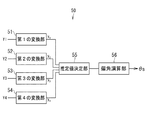
次に、図4を参照して、角度演算部50の構成と角度検出値θsの生成方法について具体的に説明する。本実施の形態では、角度演算部50における演算は、例えば、複素数を用いて行われる。図4は、角度演算部50の構成の一例を示すブロック図である。この例では、角度演算部50は、第1の変換部51と、第2の変換部52と、第3の変換部53と、第4の変換部54と、推定値決定部55と、偏角演算部56とを含んでいる。
Next, the configuration of the
第1の変換部51は、第1の合成磁界情報を表すベクトルY1を複素数y1に変換する。複素数y1の実部Re1と虚部Im1は、それぞれ下記の式(9A)、(9B)によって表される。 First converting section 51 converts the vector Y1 representing the first resultant magnetic field information in complex number y 1. The real part Re 1 and the imaginary part Im 1 of the complex number y 1 are represented by the following equations (9A) and (9B), respectively.
Re1=A1・cosθ1 …(9A)
Im1=A1・sinθ1 …(9B)
Re 1 = A 1 · cos θ 1 (9A)
Im 1 = A 1 · sin θ 1 (9B)
第2の変換部52は、第2の合成磁界情報を表すベクトルY2を複素数y2に変換する。複素数y2の実部Re2と虚部Im2は、それぞれ下記の式(10A)、(10B)によって表される。
The
Re2=A2・cosθ2 …(10A)
Im2=A2・sinθ2 …(10B)
Re 2 = A 2 · cos θ 2 (10A)
Im 2 = A 2 · sin θ 2 (10B)
第3の変換部53は、第3の合成磁界情報を表すベクトルY3を複素数y3に変換する。複素数y3の実部Re3と虚部Im3は、それぞれ下記の式(11A)、(11B)によって表される。 The third conversion section 53 converts the vector Y3 representing a third combined magnetic field information of a complex number y 3. The real part Re 3 and the imaginary part Im 3 of the complex number y 3 are represented by the following equations (11A) and (11B), respectively.
Re3=A3・cosθ3 …(11A)
Im3=A3・sinθ3 …(11B)
Re 3 = A 3 · cos θ 3 (11A)
Im 3 = A 3 · sin θ 3 (11B)
第4の変換部54は、第4の合成磁界情報を表すベクトルY4を複素数y4に変換する。複素数y4の実部Re4と虚部Im4は、それぞれ下記の式(12A)、(12B)によって表される。 The fourth conversion unit 54 converts the vector Y4 representing a fourth combined magnetic field information of a complex number y 4. The real part Re 4 and the imaginary part Im 4 of the complex number y 4 are represented by the following equations (12A) and (12B), respectively.
Re4=A4・cosθ4 …(12A)
Im4=A4・sinθ4 …(12B)
Re 4 = A 4 · cos θ 4 (12A)
Im 4 = A 4 · sin θ 4 (12B)
推定値決定部55は、ベクトルY1〜Y4と対応関係を有する複素数y1〜y4を用いて、第1および第2の推定値M,Eを決定する。ここで、それぞれ第1ないし第4の合成磁界情報の推定情報である第1ないし第4の推定合成磁界情報を、記号z1,z2,z3,z4で表す。本実施の形態では、第1ないし第4の推定合成磁界情報z1〜z4を、下記の式(13)のようにモデル化する。
The estimated

式(13)の左辺の4次元列ベクトルは、式(5)におけるzに対応する。 The four-dimensional column vector on the left side of Equation (13) corresponds to z in Equation (5).
式(13)の右辺の4行2列の行列は、式(5)におけるHに対応する。以下、この行列を記号Hcで表す。行列Hcの第1列の4つの要素は、第1ないし第4の検出位置P1〜P4における検出対象磁界、すなわち第1ないし第4の部分磁界MFa〜MFdの態様に応じて規定される。本実施の形態では、第1ないし第4の部分磁界MFa〜MFdの方向が互いに等しく、検出対象磁界の強度が磁界発生部5から検出位置までの距離の3乗に反比例して小さくなると仮定して、行列Hcの第1列の4つの要素を規定した。具体的には、式(13)に示したように、行列Hcの第1列の4つの要素を、r1,r2,r3,r4を用いて規定した。r1,r2,r3,r4は、それぞれ、磁界発生部5から前記所定の位置までの距離に対する、磁界発生部5から検出位置P1,P2,P3,P4までの距離の比率である。
The 4 × 2 matrix on the right side of Equation (13) corresponds to H in Equation (5). Hereinafter, this matrix is represented by the symbol H c . The four elements in the first column of the matrix H c are defined according to the detection target magnetic field at the first to fourth detection positions P1 to P4, that is, the first to fourth partial magnetic fields MFa to MFd. In the present embodiment, it is assumed that the directions of the first to fourth partial magnetic fields MFa to MFd are equal to each other, and the intensity of the detection target magnetic field decreases in inverse proportion to the cube of the distance from the magnetic
行列Hcの第2列の4つの要素は、第1ないし第4の検出位置P1〜P4におけるノイズ磁界Mexの態様に応じて規定される。本実施の形態では、第1ないし第4の検出位置P1〜P4におけるノイズ磁界Mexの方向が互いに等しく、第1ないし第4の検出位置P1〜Pにおけるノイズ磁界Mexの強度が互いに等しいと仮定して、行列Hcの第2列の4つの要素を規定した。具体的には、式(13)に示したように、行列Hcの第2列の4つの要素を、いずれも1とした。 The four elements in the second column of the matrix H c are defined according to the form of the noise magnetic field Mex at the first to fourth detection positions P1 to P4. In the present embodiment, it is assumed that the directions of the noise magnetic fields Mex at the first to fourth detection positions P1 to P4 are equal to each other, and the strengths of the noise magnetic fields Mex at the first to fourth detection positions P1 to P are equal to each other. Thus, four elements of the second column of the matrix H c are defined. Specifically, as shown in Expression (13), the four elements in the second column of the matrix H c are all set to 1.
式(13)の右辺の2次元列ベクトルは、式(5)におけるxに対応する。以下、この列ベクトルを記号xcで表す。列ベクトルxcは、第1の推定値Mと第2の推定値Eを要素として含んでいる。本実施の形態では、第1および第2の推定値M,Eは、いずれも複素数である。第1の推定値Mの偏角は、角度検出値θsに対応する方向の情報を表す。第1の推定値Mの絶対値は、所定の位置における検出対象磁界の強度に対応する大きさの情報を表す。本実施の形態では、所定の位置を、前記基準位置とする。第2の推定値Eの偏角は、ノイズ磁界Mexの方向に対応する方向の情報を表す。第2の推定値Eの絶対値は、ノイズ磁界Mexの強度に対応する大きさの情報を表す。 The two-dimensional column vector on the right side of Equation (13) corresponds to x in Equation (5). Hereinafter, representative of the column vector in the symbol x c. The column vector x c includes the first estimated value M and the second estimated value E as elements. In the present embodiment, the first and second estimated values M and E are both complex numbers. The declination of the first estimated value M represents information on the direction corresponding to the detected angle value θs. The absolute value of the first estimated value M represents information of a magnitude corresponding to the intensity of the detection target magnetic field at a predetermined position. In the present embodiment, a predetermined position is set as the reference position. The declination of the second estimated value E represents information on the direction corresponding to the direction of the noise magnetic field Mex. The absolute value of the second estimated value E represents information of a magnitude corresponding to the intensity of the noise magnetic field Mex.
推定値決定部55は、式(8)に基づいて、列ベクトルxcを決定する。ここで、複素数y1〜y4を要素とする4次元列ベクトルを、記号ycで表す。列ベクトルycは、下記の式(14)によって表わされる。
The estimated
yc T=[y1,y2,y3,y4] …(14) y c T = [y 1 , y 2 , y 3 , y 4 ] (14)
推定値決定部55は、式(8)におけるH,x,yをそれぞれHc,xc,ycに置き換えた式を用いて、xcを算出する。これにより、第1および第2の推定値M,Eが決定される。
The estimated
偏角演算部56は、推定値決定部55によって決定された第1の推定値Mに基づいて、角度検出値θsを決定する。本実施の形態では、第1の推定値Mの偏角を、角度検出値θsとする。従って、偏角演算部56は、第1の推定値Mの偏角を求めることによって、角度検出値θsを算出する。具体的には、偏角演算部56は、例えば、第1の推定値Mの実部ReMと虚部ImMを用いて、下記の式(15)によってθsを算出する。
The
θs=atan(ImM/ReM) …(15) θs = atan (Im M / Re M ) (15)
θsが0°以上360°未満の範囲内では、式(15)におけるθsの解には、180°異なる2つの値がある。しかし、ReM,ImMの正負の組み合わせにより、θsの真の値が、式(15)におけるθsの2つの解のいずれであるかを判別することができる。偏角演算部56は、式(15)と、上記のReM,ImMの正負の組み合わせの判定により、0°以上360°未満の範囲内でθsを求める。
Within the range of θs between 0 ° and less than 360 °, the solution of θs in equation (15) has two values that differ by 180 °. However, it is possible to determine which of the two solutions of θs in Equation (15) is the true value of θs by the combination of Re M and Im M. The
本実施の形態では、第1ないし第4の合成磁界情報生成部10,20,30,40によって生成される第1ないし第4の合成磁界情報に基づいて、最小二乗法を用いて、角度検出値θsが生成される。第1ないし第4の検出位置P1〜P4は、互いに異なる。これにより、第1ないし第4の合成磁界情報に与えるノイズ磁界Mexの相対的な影響に違いが生じる。その結果、第1ないし第4の合成磁界情報間には、ノイズ磁界Mexに依存した違いが生じ得る。本実施の形態では特に、磁界発生部5から検出位置までの距離が大きくなるに従って、ノイズ磁界Mexの相対的な影響が大きくなる。
In the present embodiment, the angle detection is performed using the least square method based on the first to fourth combined magnetic field information generated by the first to fourth combined magnetic field
上記の性質を利用すると、所定の位置における理想的な検出対象磁界(以下、理想磁界と言う。)と、ノイズ磁界Mexを推定することができる。理想磁界とは、その方向が基準方向DRに対してなす角度が、角度センサ1の真の検出対象の角度に相当することになる仮想の磁界である。本実施の形態では特に、理想磁界の方向が基準方向DRに対してなす角度は、回転磁界角度θMと等しい。
Using the above properties, it is possible to estimate an ideal detection target magnetic field (hereinafter referred to as an ideal magnetic field) at a predetermined position and a noise magnetic field Mex. The ideal magnetic field is a virtual magnetic field in which the angle formed by the direction with respect to the reference direction DR corresponds to the angle of the true detection target of the
本実施の形態において、推定値決定部55によって決定された第1の推定値Mは、推定された理想磁界に対応し、推定値決定部55によって決定された第2の推定値Eは、推定されたノイズ磁界Mexに対応する。本実施の形態では、第1の推定値Mに基づいて角度検出値θsを決定する。これにより、本実施の形態によれば、ノイズ磁界Mexの影響が排除された角度検出値θsを推定することができる。すなわち、本実施の形態によれば、ノイズ磁界Mexに起因した角度誤差を低減することができる。
In the present embodiment, the first estimated value M determined by the estimated
なお、上述のように角度検出値θsを決定するためには、第1ないし第4の検出位置P1〜P4が互いに異なるという条件を満たす必要があるが、この条件は、角度センサ1および角度センサシステム100の構成や設置に関して大きな制約を生じさせるものではない。例えば、本実施の形態のように、磁界発生部5から第1ないし第4の検出位置P1〜P4までの距離を互いに異ならせることによって、簡単に、上記の条件を満たすことができる。
In order to determine the angle detection value θs as described above, it is necessary to satisfy the condition that the first to fourth detection positions P1 to P4 are different from each other. This condition is determined by the
以上のことから、本実施の形態によれば、角度センサ1および角度センサシステム100の構成や設置に関して大きな制約を生じさせることなく、ノイズ磁界Mexに起因した角度誤差を低減することができる。
From the above, according to the present embodiment, it is possible to reduce the angle error due to the noise magnetic field Mex without causing a great restriction on the configuration and installation of the
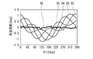
以下、シミュレーションの結果を参照して、本実施の形態の効果について説明する。シミュレーションでは、方向と強度が一定のノイズ磁界Mexが存在する状況の下で、角度θ1〜θ4および角度検出値θsを生成したときの、角度θ1〜θ4のそれぞれの角度誤差と角度検出値θsの角度誤差を求めた。なお、このシミュレーションでは、真の検出対象の角度に相当する基準角度θrを用いて、角度誤差を求めた。具体的には、角度θ1と基準角度θrの差を角度θ1の角度誤差とし、角度θ2と基準角度θrの差を角度θ2の角度誤差とし、角度θ3と基準角度θrの差を角度θ3の角度誤差とし、角度θ4と基準角度θrの差を角度θ4の角度誤差とし、角度検出値θsと基準角度θrの差を角度検出値θsの角度誤差とした。また、このシミュレーションでは、角度θ1〜θ4の値に、それぞれ乱数で生成した誤差を重畳した。この誤差は、角度センサ1において生じる通常の誤差を想定したものである。通常の誤差は、第1ないし第4の合成磁界情報生成部10,20,30,40の非線形性による誤差と白色ノイズによる誤差を含む。この通常の誤差に起因した角度誤差は、ノイズ磁界Mexに起因した角度誤差よりも十分に小さい。
Hereinafter, the effects of the present embodiment will be described with reference to the simulation results. In the simulation, under circumstances where the direction and intensity exists a certain noise field Mex, when generating the angle theta 1 through? 4 and the angle detected value [theta] s, each angular error and the angle of the angle theta 1 through? 4 The angle error of the detected value θs was obtained. In this simulation, the angle error was obtained using the reference angle θr corresponding to the angle of the true detection target. Specifically, the difference between the angle theta 1 and the reference angle θr is the angle theta 1 of the angle error, the difference between the angle theta 2 and the reference angle θr is the angle theta 2 of the angular errors, the difference between the angle theta 3 and the reference angle θr was the angle theta 3 angular error, the difference between the angle theta 4 and the reference angle θr is the angle theta 4 angular error, the difference between the detected angle value [theta] s and the reference angle θr and the angle error of the angle detection value [theta] s. In this simulation, errors generated by random numbers are superimposed on the values of the angles θ 1 to θ 4 . This error assumes a normal error that occurs in the
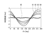
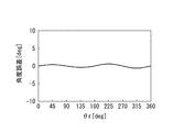
図8は、シミュレーションによって得られた角度誤差の一例を示す波形図である。図8において、横軸は基準角度θrを示し、縦軸は角度誤差を示している。また、符号81は角度θ1の角度誤差を示し、符号82は角度θ2の角度誤差を示し、符号83は角度θ3の角度誤差を示し、符号84は角度θ4の角度誤差を示し、符号85は角度検出値θsの角度誤差を示している。図8に示したように、角度検出値θsの角度誤差は、角度θ1〜θ4のそれぞれの角度誤差に比べて極めて小さい。角度θ1〜θ4の角度誤差は、主にノイズ磁界Mexに起因して生じたものである。一方、角度検出値θsの角度誤差は、主に通常の誤差に起因して生じたものである。このように、本実施の形態によれば、ノイズ磁界Mexに起因した角度誤差を低減することができる。
FIG. 8 is a waveform diagram showing an example of the angle error obtained by the simulation. In FIG. 8, the horizontal axis represents the reference angle θr, and the vertical axis represents the angle error.
図8に示したように、角度θ1〜θ4の角度誤差の振幅は、互いに異なる。これは、第1ないし第4の合成磁界情報に与えるノイズ磁界Mexの相対的な影響の違いに起因するものである。本実施の形態では、第1ないし第4の検出位置P1,P2,P3,P4は、磁界発生部5から遠ざかる方向に、この順に並んでいる。そのため、第1ないし第4の部分磁界MFa,MFb,MFc,MFdの強度は、この順に小さくなる。その結果、角度θ1,θ2,θ3,θ4の角度誤差の振幅は、この順に大きくなる。
As shown in FIG. 8, the amplitudes of the angle errors of the angles θ 1 to θ 4 are different from each other. This is due to the difference in the relative influence of the noise magnetic field Mex on the first to fourth synthesized magnetic field information. In the present embodiment, the first to fourth detection positions P1, P2, P3, and P4 are arranged in this order in the direction away from the
[第2の実施の形態]
次に、本発明の第2の実施の形態について説明する。始めに、図9を参照して、本実施の形態に係る角度センサシステム100の構成について説明する。本実施の形態に係る角度センサシステム100は、以下の点で第1の実施の形態と異なっている。図9に示したように、本実施の形態では、第1ないし第4の検出位置P1〜P4は、磁石6の一方の端面に平行な同一平面上にある。以下、第1ないし第4の検出位置P1〜P4を含む仮想の平面を記号Pで表す。本実施の形態では特に、磁界発生部5からの距離が互いに等しくなるように、第1ないし第4の検出位置P1〜P4が規定されている。第1ないし第4の検出位置P1〜P4は、図9に示したように、仮想の平面P上にある、回転中心Cを中心とした1つの円の円周上にあってもよい。図9に示した例では、第1ないし第4の検出位置P1〜P4は、上記円周上において、反時計回り方向に、この順に並んでいる。なお、必ずしも、第1ないし第4の検出位置P1〜P4の全てが上記円周上にある必要はない。
[Second Embodiment]
Next, a second embodiment of the present invention will be described. First, the configuration of the
第1の実施の形態と同様に、第1の検出位置P1における検出対象磁界を特に第1の部分磁界MFaと言い、第2の検出位置P2における検出対象磁界を特に第2の部分磁界MFbと言い、第3の検出位置P3における検出対象磁界を特に第3の部分磁界MFcと言い、第4の検出位置P4における検出対象磁界を特に第4の部分磁界MFdと言う。 As in the first embodiment, the detection target magnetic field at the first detection position P1 is particularly referred to as a first partial magnetic field MFa, and the detection target magnetic field at the second detection position P2 is particularly referred to as a second partial magnetic field MFb. That is, the detection target magnetic field at the third detection position P3 is particularly referred to as a third partial magnetic field MFc, and the detection target magnetic field at the fourth detection position P4 is particularly referred to as a fourth partial magnetic field MFd.
第1ないし第4の部分磁界MFa〜MFdの方向は、理想的には、第1の実施の形態で説明した理想磁界の方向と一致する。しかし、本実施の形態のように、第1ないし第4の検出位置P1〜P4が回転中心Cから離れた位置にある場合には、第1ないし第4の部分磁界MFa〜MFdの方向が、常に理想磁界の方向と一致するとは限らない。 The directions of the first to fourth partial magnetic fields MFa to MFd ideally coincide with the direction of the ideal magnetic field described in the first embodiment. However, when the first to fourth detection positions P1 to P4 are located away from the rotation center C as in the present embodiment, the directions of the first to fourth partial magnetic fields MFa to MFd are It does not always match the direction of the ideal magnetic field.
ここで、第1ないし第4の部分磁界MFa〜MFdの方向が理想磁界の方向に対してなす角度を、それぞれ、第1ないし第4の部分磁界MFa〜MFdの方向誤差と言う。第1ないし第4の部分磁界MFa〜MFdの方向誤差は、第1の実施の形態で説明した角度θ1〜θ4の角度誤差を生じさせる。検出対象の角度が所定の周期で変化する場合、第1ないし第4の部分磁界MFa〜MFdの方向誤差は、上記所定の周期の1/2の周期で変化し、且つその変化の位相が互いに異なる。従って、検出対象の角度に応じた第1ないし第4の部分磁界MFa〜MFdの方向の変化の態様は、互いに異なる。 Here, the angles formed by the directions of the first to fourth partial magnetic fields MFa to MFd with respect to the direction of the ideal magnetic field are referred to as direction errors of the first to fourth partial magnetic fields MFa to MFd, respectively. The direction errors of the first to fourth partial magnetic fields MFa to MFd cause the angle errors of the angles θ 1 to θ 4 described in the first embodiment. When the angle of the detection target changes in a predetermined cycle, the direction errors of the first to fourth partial magnetic fields MFa to MFd change in a cycle that is ½ of the predetermined cycle, and the phases of the changes are mutually different. Different. Therefore, the changes in the directions of the first to fourth partial magnetic fields MFa to MFd according to the angle of the detection target are different from each other.
次に、本実施の形態における角度検出値θsの生成方法について説明する。角度検出値θsの生成方法は、基本的には、第1の実施の形態と同じである。ただし、本実施の形態では、第1ないし第4の推定合成磁界情報z1〜z4を、下記の式(16)のようにモデル化する。 Next, a method for generating the detected angle value θs in the present embodiment will be described. The method for generating the detected angle value θs is basically the same as in the first embodiment. However, in the present embodiment, the first to fourth estimated synthesized magnetic field information z 1 to z 4 are modeled as the following equation (16).
式(16)の右辺の4行2列の行列は、第1の実施の形態で説明した式(5)におけるHに対応する。以下、この行列を記号Hdで表す。行列Hdの第1列の4つの要素は、第1ないし第4の部分磁界MFa〜MFdの態様に応じて規定される。本実施の形態では、式(16)に示したように、行列Hdの第1列の4つの要素を、“Ansin(2θ+αn)”(nは1以上4以下の整数)を用いて規定した。Anは、第1ないし第4の部分磁界MFa〜MFdの方向誤差の周期的な変化の振幅を表す。αnは、第1ないし第4の部分磁界MFa〜MFdの方向誤差の周期的な変化の位相の違いを表す値である。前述のように、第1ないし第4の部分磁界MFa〜MFdの方向誤差は、角度θ1〜θ4の角度誤差を生じさせる。従って、A1〜A4,α1〜α4は、角度θ1〜θ4の角度誤差の波形から求めることができる。 The matrix of 4 rows and 2 columns on the right side of Expression (16) corresponds to H in Expression (5) described in the first embodiment. Hereinafter, this matrix is represented by the symbol H d . The four elements in the first column of the matrix H d are defined according to the modes of the first to fourth partial magnetic fields MFa to MFd. In the present embodiment, as shown in Expression (16), “A n sin (2θ + α n )” (n is an integer of 1 to 4) is used for the four elements in the first column of the matrix H d . Stipulated. A n represents the amplitude of the periodic variation in the direction error of the first to fourth partial magnetic field MFa~MFd. α n is a value representing a phase difference of a periodic change in the direction error of the first to fourth partial magnetic fields MFa to MFd. As described above, the direction errors of the first to fourth partial magnetic fields MFa to MFd cause the angle errors of the angles θ 1 to θ 4 . Therefore, A 1 to A 4 and α 1 to α 4 can be obtained from the waveform of the angle error of the angles θ 1 to θ 4 .
θは、角度センサ1の真の検出対象の角度を表している。本実施の形態では、角度検出値θsを生成する際には、式(16)におけるθに、暫定的に算出される角度検出値θsに対応する値θpを代入する。具体的には、例えば、角度θ1〜θ4の平均値を、θpとする。
θ represents the angle of the true detection target of the
行列Hdの第2列の4つの要素は、第1ないし第4の検出位置P1〜P4におけるノイズ磁界Mexの態様に応じて規定される。本実施の形態では、第1の実施の形態と同様に、行列Hdの第2列の4つの要素を、いずれも1とした。 The four elements in the second column of the matrix H d are defined according to the form of the noise magnetic field Mex at the first to fourth detection positions P1 to P4. In the present embodiment, as in the first embodiment, all four elements in the second column of the matrix H d are set to 1.
本実施の形態では、推定値決定部55(図4参照)は、第1の実施の形態における行列Hcの代わりに行列Hdを用いて、第1および第2の推定値M,Eを決定する。 In the present embodiment, the estimated value determining unit 55 (see FIG. 4) uses the matrix H d instead of the matrix H c in the first embodiment to calculate the first and second estimated values M and E. decide.
第1の実施の形態で説明したように、第1ないし第4の検出位置P1〜P4が互いに異なることにより、第1ないし第4の合成磁界情報に与えるノイズ磁界Mexの相対的な影響に違いが生じる。本実施の形態では特に、検出対象の角度に応じた第1ないし第4の部分磁界MFa〜MFdの方向の変化の態様が互いに異なるように、第1ないし第4の検出位置P1〜P4を規定している。これにより、第1ないし第4の合成磁界情報に与えるノイズ磁界Mexの相対的な影響に違いが生じる。その結果、第1ないし第4の合成磁界情報間には、ノイズ磁界Mexに依存した違いが生じ得る。第1の実施の形態で説明したように、この性質を利用すると、理想磁界とノイズ磁界Mexを推定することができる。 As described in the first embodiment, when the first to fourth detection positions P1 to P4 are different from each other, the relative influence of the noise magnetic field Mex on the first to fourth synthesized magnetic field information is different. Occurs. In the present embodiment, in particular, the first to fourth detection positions P1 to P4 are defined so that the change modes of the directions of the first to fourth partial magnetic fields MFa to MFd according to the angle of the detection target are different from each other. doing. Thereby, a difference arises in the relative influence of the noise magnetic field Mex given to the 1st thru | or 4th synthetic | combination magnetic field information. As a result, a difference depending on the noise magnetic field Mex may occur between the first to fourth synthesized magnetic field information. As described in the first embodiment, the ideal magnetic field and the noise magnetic field Mex can be estimated by using this property.
次に、シミュレーションの結果を参照して、本実施の形態の効果について説明する。シミュレーションの内容は、第1の実施の形態におけるシミュレーションと同じである。 Next, the effects of the present embodiment will be described with reference to the simulation results. The content of the simulation is the same as the simulation in the first embodiment.
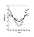
図10は、シミュレーションによって得られた角度誤差の一例を示す波形図である。図10において、横軸は基準角度θrを示し、縦軸は角度誤差を示している。また、符号91は角度θ1の角度誤差を示し、符号92は角度θ2の角度誤差を示し、符号93は角度θ3の角度誤差を示し、符号94は角度θ4の角度誤差を示し、符号95は角度検出値θsの角度誤差を示している。図10に示したように、角度検出値θsの角度誤差は、角度θ1〜θ4の角度誤差に比べて極めて小さい。角度θ1〜θ4の角度誤差は、主にノイズ磁界Mexと第1ないし第4の部分磁界MFa〜MFdの方向誤差に起因して生じたものである。一方、角度検出値θsの角度誤差は、主に通常の誤差に起因して生じたものである。このように、本実施の形態によれば、ノイズ磁界Mexと第1ないし第4の部分磁界MFa〜MFdの方向誤差に起因した角度誤差を低減することができる。なお、図10に示したように、基準角度θrに応じた角度θ1〜θ4の角度誤差の変化の位相は、互いに異なる。これは、基準角度θrに応じた第1ないし第4の部分磁界MFa〜MFdの方向誤差の周期的な変化の位相の違いによるものである。
FIG. 10 is a waveform diagram showing an example of the angle error obtained by the simulation. In FIG. 10, the horizontal axis represents the reference angle θr, and the vertical axis represents the angle error.
本実施の形態におけるその他の構成、作用および効果は、第1の実施の形態と同様である。 Other configurations, operations, and effects in the present embodiment are the same as those in the first embodiment.
[第3の実施の形態]
次に、本発明の第3の実施の形態について説明する。始めに、図11を参照して、本実施の形態に係る角度センサ1の構成について説明する。本実施の形態に係る角度センサ1の構成は、以下の点で第1および第2の実施の形態と異なっている。本実施の形態では、第1および第2の実施の形態における第1ないし第4のベクトル生成部15,25,35,45が設けられていない。また、本実施の形態に係る角度センサ1は、第1および第2の実施の形態における角度演算部50の代わりに、角度演算部250を備えている。角度演算部250は、例えば、ASICまたはマイクロコンピュータによって実現することができる。
[Third Embodiment]
Next, a third embodiment of the present invention will be described. First, the configuration of the
本実施の形態では、第1および第2の実施の形態と同様に、第1の合成磁界情報はベクトルY1によって表わされ、第2の合成磁界情報はベクトルY2によって表わされ、第3の合成磁界情報はベクトルY3によって表わされ、第4の合成磁界情報はベクトルY4によって表わされる。本実施の形態では特に、第1および第2の検出信号S1,S2を、直交座標系におけるベクトルY1の2つの成分とし、第3および第4の検出信号S3,S4を、直交座標系におけるベクトルY2の2つの成分とし、第5および第6の検出信号S5,S6を、直交座標系におけるベクトルY3の2つの成分とし、第7および第8の検出信号S7,S8を、直交座標系におけるベクトルY4の2つの成分とする。なお、このようにするためには、第1ないし第8の検出信号S1〜S8の大きさが、第1ないし第4の合成磁界MF1〜MF4の強度の範囲内では飽和しないという条件の下で、第1ないし第8の検出信号生成部11,12,21,22,31,32,41,42を使用する必要がある。
In the present embodiment, as in the first and second embodiments, the first combined magnetic field information is represented by the vector Y1, the second combined magnetic field information is represented by the vector Y2, and the third The combined magnetic field information is represented by a vector Y3, and the fourth combined magnetic field information is represented by a vector Y4. In the present embodiment, in particular, the first and second detection signals S1, S2 are two components of the vector Y1 in the orthogonal coordinate system, and the third and fourth detection signals S3, S4 are the vectors in the orthogonal coordinate system. Two components of Y2, the fifth and sixth detection signals S5 and S6 are two components of vector Y3 in the orthogonal coordinate system, and the seventh and eighth detection signals S7 and S8 are vectors in the orthogonal coordinate system. Let Y4 be two components. For this purpose, the first to eighth detection signals S1 to S8 are not saturated within the range of the strengths of the first to fourth synthetic magnetic fields MF1 to MF4. The first to eighth
また、本実施の形態では、角度演算部250における演算は、角度演算部50と同様に、複素数を用いて行われる。図11には、角度演算部250の構成の一例を示している。この例では、角度演算部250は、推定値決定部251と、偏角演算部252とを含んでいる。角度演算部250では、直交座標系におけるベクトルY1の2つの成分を、複素数y1の実部Re1と虚部Im1とし、直交座標系におけるベクトルY2の2つの成分を、複素数y2の実部Re2と虚部Im2とし、直交座標系におけるベクトルY3の2つの成分を、複素数y3の実部Re3と虚部Im3とし、直交座標系におけるベクトルY4の2つの成分を、複素数y4の実部Re4と虚部Im4とする。具体的には、それぞれA/D変換器13,14によってデジタル信号に変換された第1および第2の検出信号S1,S2を、複素数y1の実部Re1と虚部Im1とし、それぞれA/D変換器23,24によってデジタル信号に変換された第3および第4の検出信号S3,S4を、複素数y2の実部Re2と虚部Im2とし、それぞれA/D変換器33,34によってデジタル信号に変換された第5および第6の検出信号S5,S6を、複素数y3の実部Re3と虚部Im3とし、それぞれA/D変換器43,44によってデジタル信号に変換された第7および第8の検出信号S7,S8を、複素数y4の実部Re4と虚部Im4としている。
In the present embodiment, the calculation in the
推定値決定部251は、複素数y1〜y4を用いて、第1および第2の推定値M,Eを決定する。第1および第2の推定値M,Eの決定方法は、第1または第2の実施の形態と同じである。
The estimated
偏角演算部252は、第1の推定値Mに基づいて、角度検出値θsを決定する。第1の実施の形態で説明したように、第1の推定値Mは、複素数である。本実施の形態では、第1の推定値Mの偏角を、角度検出値θsとする。偏角演算部252は、第1の推定値Mの偏角を求めることによって、角度検出値θsを算出する。角度検出値θsの算出方法は、第1の実施の形態と同じである。
The deflection
本実施の形態では、第1および第2の検出信号S1,S2が、直接、複素数y1の実部Re1と虚部Im1として用いられ、第3および第4の検出信号S3,S4が、直接、複素数y2の実部Re2と虚部Im2として用いられ、第5および第6の検出信号S5,S6が、直接、複素数y3の実部Re3と虚部Im3として用いられ、第7および第8の検出信号S7,S8が、直接、複素数y4の実部Re4と虚部Im4として用いられる。そのため、本実施の形態では、第1の実施の形態で説明した、方向D1〜D4、大きさMa1〜Ma4、実部Re1〜Re4ならびに虚部Im1〜Im4を求めるための演算が不要になる。これにより、本実施の形態によれば、第1および第2の実施の形態に比べて、角度センサ1の構成が簡単になると共に、角度検出値θsの生成が容易になる。
In the present embodiment, the first and second detection signals S1 and S2 are directly used as the real part Re 1 and the imaginary part Im 1 of the complex number y 1 , and the third and fourth detection signals S3 and S4 are used. Are directly used as the real part Re 2 and the imaginary part Im 2 of the complex number y 2 , and the fifth and sixth detection signals S5 and S6 are directly used as the real part Re 3 and the imaginary part Im 3 of the complex number y 3. is, the detection signal S7, S8 of the seventh and eighth, directly used as the real part Re 4 and the imaginary part Im 4 complex y 4. Therefore, in this embodiment, the directions D 1 to D 4 , the sizes Ma 1 to Ma 4 , the real parts Re 1 to Re 4, and the imaginary parts Im 1 to Im 4 described in the first embodiment are obtained. For this is not necessary. Thereby, according to the present embodiment, the configuration of the
本実施の形態におけるその他の構成、作用および効果は、第1または第2の実施の形態と同様である。 Other configurations, operations, and effects in the present embodiment are the same as those in the first or second embodiment.
[第4の実施の形態]
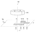
次に、本発明の第4の実施の形態について説明する。始めに、図12を参照して、本実施の形態に係る角度センサシステム100の構成について説明する。本実施の形態に係る角度センサシステム100は、以下の点で第2の実施の形態と異なっている。本実施の形態では、複数の検出位置の数をN(Nは2以上の整数)で表す。N個の検出位置は、いずれも、仮想の平面P上にある。N個の検出位置におけるノイズ磁界Mexの方向は互いに等しく、N個の検出位置におけるノイズ磁界Mexの強度は互いに等しい。
[Fourth Embodiment]
Next, a fourth embodiment of the present invention will be described. First, the configuration of the
本実施の形態では、N個の検出位置のうちの少なくとも2つの検出位置において、検出対象磁界の強度が互いに異なるように、N個の検出位置が規定される。基準平面P上では、検出対象磁界の強度は、回転中心Cからの距離に依存して変化する。従って、N個の検出位置のうちの少なくとも2つの検出位置は、回転中心Cからの距離が互いに異なる。上記の要件を満たす限り、検出対象磁界の強度が互いに等しい複数の検出位置が存在していてもよい。 In the present embodiment, N detection positions are defined such that at least two detection positions among the N detection positions have different detection target magnetic field strengths. On the reference plane P, the intensity of the detection target magnetic field changes depending on the distance from the rotation center C. Accordingly, at least two of the N detection positions have different distances from the rotation center C. As long as the above requirements are satisfied, there may be a plurality of detection positions having the same intensity of the detection target magnetic field.
また、本実施の形態に係る角度センサ1は、第2の実施の形態における第1ないし第4の合成磁界情報生成部10,20,30,40の代わりに、N個の合成磁界情報生成部を備えている。以下、N個の合成磁界情報生成部を、便宜上、1番目ないしN番目の合成磁界情報生成部と呼ぶ。そして、n番目(nは1以上N以下の任意の整数)の合成磁界情報生成部を、符号10Inで表す。
In addition, the
ここで、合成磁界情報生成部10Inに対応する検出位置を、符号Pnで表す。合成磁界情報生成部10Inは、検出位置Pnにおいて、検出対象磁界とノイズ磁界Mexとの合成磁界を検出し、合成磁界情報を生成する。本実施の形態では、複数の合成磁界情報の各々は、合成磁界の方向の情報を含む。 Here, the detection position corresponding to the synthetic magnetic field information generation unit 10I n is represented by a symbol P n . The combined magnetic field information generation unit 10I n detects a combined magnetic field of the detection target magnetic field and the noise magnetic field Mex at the detection position P n and generates combined magnetic field information. In the present embodiment, each of the plurality of combined magnetic field information includes information on the direction of the combined magnetic field.
また、合成磁界情報生成部10Inが検出する合成磁界が基準方向DRに対してなす角度を記号θnで表す。図12には、第1の実施の形態で説明したX,Y,Zの各方向を示している。基準方向DRは、X方向とする。後で詳しく説明するが、合成磁界情報生成部10Inは、合成磁界情報として、角度θnを表す個別角度値θsnを生成する。角度θnおよび個別角度値θsnの正負の定義は、第1の実施の形態における角度θ1〜θ4と同様である。 Further, representing the angle at which the combined magnetic field of the composite magnetic field information generating unit 10I n detects with respect to the reference direction DR by the symbol theta n. FIG. 12 shows the X, Y, and Z directions described in the first embodiment. The reference direction DR is the X direction. As will be described in detail later, the combined magnetic field information generation unit 10I n generates an individual angle value θs n representing the angle θ n as the combined magnetic field information. Definitions of positive and negative of the angle θ n and the individual angle value θs n are the same as the angles θ 1 to θ 4 in the first embodiment.
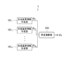
次に、図13および図14を参照して、本実施の形態に係る角度センサ1および合成磁界情報生成部10Inの構成について詳しく説明する。図13は、角度センサ1の構成を示す機能ブロック図である。図14は、合成磁界情報生成部10Inの構成の一例を示す機能ブロック図である。前述のように、本実施の形態に係る角度センサ1は、N個の合成磁界情報生成部10I1,10I2,…,10INを備えている。
Next, with reference to FIGS. 13 and 14, will be described in detail configuration of the
図14に示した例では、合成磁界情報生成部10Inは、第1の信号生成部11Iと、第2の信号生成部12Iと、A/D変換器13I,14Iと、個別角度演算部15Iとを有している。第1の信号生成部11Iは、検出位置Pnにおける合成磁界の方向が基準方向DRに対してなす角度θnの余弦と対応関係を有する第1の信号S1nを生成する。第2の信号生成部12Iは、検出位置Pnにおける合成磁界の方向が基準方向DRに対してなす角度θnの正弦と対応関係を有する第2の信号S2nを生成する。A/D変換器13I,14Iは、それぞれ、第1および第2の信号S1n,S2nをデジタル信号に変換する。個別角度演算部15Iは、第1および第2の信号S1n,S2nに基づいて、合成磁界情報として、角度θnを表す個別角度値θsnを生成する。個別角度値θsnは、検出位置Pnにおける合成磁界の方向の情報に対応する。個別角度演算部15Iは、例えば、ASICによって実現することができる。
In the example illustrated in FIG. 14, the synthesized magnetic field information generation unit 10I n includes a first
本実施の形態では第1の信号生成部11Iの構成は、第1の実施の形態において図5を参照して説明した第1の検出信号生成部11の構成と同じである。そのため、以下の説明では、第1の信号生成部11Iの構成要素について、図5に示した第1の検出信号生成部11の構成要素と同じ符号を用いる。第1の信号生成部11Iでは、磁気検出素子R11,R14に含まれる複数のMR素子における磁化固定層の磁化の方向はX方向であり、磁気検出素子R12,R13に含まれる複数のMR素子における磁化固定層の磁化の方向は−X方向である。この場合、角度θnの余弦に応じて、出力ポートE11,E12の電位差が変化する。差分検出器18は、出力ポートE11,E12の電位差に対応する信号を第1の信号S1nとして出力する。従って、第1の信号生成部11Iは、角度θnの余弦と対応関係を有する第1の信号S1nを生成する。
In the present embodiment, the configuration of the first
また、本実施の形態では、第2の信号生成部12Iの構成は、第1の実施の形態において図6を参照して説明した第2の検出信号生成部12の構成と同じである。そのため、以下の説明では、第2の信号生成部12Iの構成要素について、図6に示した第2の検出信号生成部12の構成要素と同じ符号を用いる。第2の信号生成部12Iでは、磁気検出素子R21,R24に含まれる複数のMR素子における磁化固定層の磁化の方向はY方向であり、磁気検出素子R22,R23に含まれる複数のMR素子における磁化固定層の磁化の方向は−Y方向である。この場合、角度θnの正弦に応じて、出力ポートE21,E22の電位差が変化する。差分検出器28は、出力ポートE21,E22の電位差に対応する信号を第2の信号S2nとして出力する。従って、第2の信号生成部12Iは、角度θnの正弦と対応関係を有する第2の信号S2nを生成する。
Further, in the present embodiment, the configuration of the second signal generation unit 12I is the same as the configuration of the second detection
次に、個別角度値θsnの生成方法について具体的に説明する。個別角度演算部15Iは、下記の式(17)によって、個別角度値θsnを求める。 Next, a method for generating the individual angle value θs n will be specifically described. The individual angle calculation unit 15I obtains the individual angle value θs n by the following equation (17).
θsn=atan(S2n/S1n) …(17) θs n = atan (S2 n / S1 n ) (17)
θsnが0°以上360°未満の範囲内では、式(17)におけるθsnの解には、180°異なる2つの値がある。しかし、S1n,S2nの正負の組み合わせにより、θsnの真の値が、式(17)におけるθsnの2つの解のいずれであるかを判別することができる。個別角度演算部15Iは、式(17)と、上記のS1n,S2nの正負の組み合わせの判定により、0°以上360°未満の範囲内でθsnを求める。 Within the range of θs n between 0 ° and less than 360 °, the solution of θs n in Equation (17) has two values that differ by 180 °. However, it is possible to determine which of the two solutions of θs n in Expression (17) is the true value of θs n by the combination of S1 n and S2 n . The individual angle calculation unit 15I obtains θs n within a range of 0 ° or more and less than 360 ° based on the determination of Expression (17) and the positive / negative combination of S1 n and S2 n .
図13に示したように、本実施の形態に係る角度センサ1は、第2の実施の形態における角度演算部50の代わりに、角度演算部350を備えている。角度演算部350は、複数の合成磁界情報すなわちN個の個別角度値θs1,θs2,…,θsNに基づいて、最小二乗法を用いて、角度検出値θsを生成する。角度演算部350は、例えば、ASICまたはマイクロコンピュータによって実現することができる。
As shown in FIG. 13, the
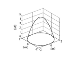
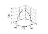
次に、本実施の形態における検出対象磁界の一例と合成磁界の一例について説明する。本実施の形態では、磁界発生部5が発生する検出対象磁界として、基準平面P上において、回転中心C(図12参照)から遠ざかるに従って強度が減少する磁界を想定する。図15は、検出対象磁界の強度の分布を模式的に示す説明図である。図15における縦軸は、検出対象磁界の強度(単位はmT)を示している。また、図15において、縦軸に直交する2つの軸は、基準平面P上の直交する2方向の位置(単位はmm)を示している。図15では、基準平面Pと回転中心Cとの交点(図12参照)を、この縦軸に直交する2つの軸の原点とした。
Next, an example of the detection target magnetic field and an example of the combined magnetic field in the present embodiment will be described. In the present embodiment, the detection target magnetic field generated by the magnetic
図16は、合成磁界の強度および方向の、基準平面P上での分布を模式的に示す説明図である。図16における合成磁界は、図15に示した検出対象磁界とノイズ磁界Mexとが合成されたものである。図16では、ノイズ磁界Mexの強度を1mTとし、ノイズ磁界Mexの方向を、X方向からY方向に向かって60°だけ回転した方向とした。また、図16では、基準平面Pと回転中心C(図12参照)との交点を原点とした。図16における各軸の単位は、mmである。図16において、矢印は、回転磁界角度θMが0°のときの上記合成磁界の強度および方向を表している。矢印の長さは合成磁界の強度を表し、矢印の方向は合成磁界の方向を表している。 FIG. 16 is an explanatory diagram schematically showing the distribution on the reference plane P of the intensity and direction of the combined magnetic field. The combined magnetic field in FIG. 16 is a combination of the detection target magnetic field and the noise magnetic field Mex shown in FIG. In FIG. 16, the intensity of the noise magnetic field Mex is 1 mT, and the direction of the noise magnetic field Mex is a direction rotated by 60 ° from the X direction toward the Y direction. In FIG. 16, the intersection of the reference plane P and the rotation center C (see FIG. 12) is set as the origin. The unit of each axis in FIG. 16 is mm. In FIG. 16, arrows indicate the strength and direction of the combined magnetic field when the rotating magnetic field angle θM is 0 °. The length of the arrow represents the strength of the combined magnetic field, and the direction of the arrow represents the direction of the combined magnetic field.
次に、本実施の形態におけるノイズ磁界Mexと個別角度値θsnとの関係について説明する。ノイズ磁界Mexが存在しない場合には、個別角度値θsnは、回転磁界角度θMと等しくなる。しかし、ノイズ磁界Mexが存在すると、検出位置Pnにおける合成磁界の方向が検出位置Pnにおける検出対象磁界の方向からずれて、その結果、個別角度値θsnが回転磁界角度θMとは異なる値になる場合がある。以下、個別角度値θsnと回転磁界角度θMの差を、個別角度値θsnの角度誤差と言う。個別角度値θsnの角度誤差は、ノイズ磁界Mexに起因して生じる。 Next, the relationship between the noise magnetic field Mex and the individual angle value θs n in the present embodiment will be described. When the noise magnetic field Mex does not exist, the individual angle value θs n is equal to the rotating magnetic field angle θM. However, when the noise field Mex exists, offset direction of the resultant magnetic field at the detection position P n from the direction of the detection target magnetic field at the detection position P n, as a result, the individual angle value [theta] s n different from the rotating magnetic field angle θM value It may become. Hereinafter, the difference between the individual angle value θs n and the rotating magnetic field angle θM is referred to as an angle error of the individual angle value θs n . The angle error of the individual angle value θs n is caused by the noise magnetic field Mex.
また、前述のように、本実施の形態では、複数の検出位置P1,P2,…,PNのうちの少なくとも2つの検出位置において、検出対象磁界の強度は、互いに異なる。基準平面P上では、検出対象磁界の強度は、回転中心Cからの距離に依存して変化する。少なくとも2つの検出位置において、検出対象磁界の強度が異なると、それらの検出位置における合成磁界に与えるノイズ磁界Mexの相対的な影響が変化して、それらの検出位置における合成磁界の方向に違いが生じる。その結果、個別角度値θsnに違いが生じる。 Further, as described above, in this embodiment, a plurality of detection positions P 1, P 2, ..., at least two detection positions of the P N, the strength of the detected magnetic field are different from each other. On the reference plane P, the intensity of the detection target magnetic field changes depending on the distance from the rotation center C. If the intensity of the magnetic field to be detected is different at at least two detection positions, the relative influence of the noise magnetic field Mex on the combined magnetic field at those detection positions changes, and the direction of the combined magnetic field at these detection positions differs. Arise. As a result, a difference occurs in the individual angle value θs n .
以下、検出位置P1における合成磁界と検出位置P2における合成磁界を例にとって、ノイズ磁界Mexの影響について説明する。本実施の形態では、符号MF1は、検出位置P1における合成磁界を表すものとし、符号MF2は、検出位置P2における合成磁界を表すものとする。以下、合成磁界MF1を第1の合成磁界MF1とも言い、合成磁界MF2を第2の合成磁界MF2とも言う。また、本実施の形態では、符号MFaは、検出位置P1における検出対象磁界を表すものとし、符号MFbは、検出位置P2における検出対象磁界を表すものとする。以下、検出対象磁界MFaを第1の部分磁界MFaとも言い、検出対象磁界MFbを第2の部分磁界MFbとも言う。第1の部分磁界MFaの方向と第2の部分磁界MFbの方向は、基準位置における検出対象磁界の方向に一致するものとする。 Hereinafter, the influence of the noise magnetic field Mex will be described by taking the combined magnetic field at the detection position P 1 and the combined magnetic field at the detection position P 2 as an example. In this embodiment, code MF1 is intended to represent the combined magnetic field at the detection position P 1, reference numeral MF2 denote the combined magnetic field at the detection position P 2. Hereinafter, the combined magnetic field MF1 is also referred to as a first combined magnetic field MF1, and the combined magnetic field MF2 is also referred to as a second combined magnetic field MF2. In the present embodiment, the symbol MFa represents a detection target magnetic field at the detection position P 1 , and the symbol MFb represents a detection target magnetic field at the detection position P 2 . Hereinafter, the detection target magnetic field MFa is also referred to as a first partial magnetic field MFa, and the detection target magnetic field MFb is also referred to as a second partial magnetic field MFb. It is assumed that the direction of the first partial magnetic field MFa and the direction of the second partial magnetic field MFb coincide with the direction of the detection target magnetic field at the reference position.
ここで、ノイズ磁界Mexについて、第1および第2の部分磁界MFa,MFbに直交する成分(以下、第1の成分と言う。)と、第1および第2の部分磁界MFa,MFbに平行な成分(以下、第2の成分と言う。)を想定する。図17は、第1および第2の合成磁界MF1,MF2とノイズ磁界Mexとの関係を模式的に示す説明図である。図17における(a)は第1の合成磁界MF1とノイズ磁界Mexの第1の成分との関係を示している。図17における(b)は第2の合成磁界MF2とノイズ磁界Mexの第1の成分との関係を示している。図17において、記号Mex1を付した矢印は、ノイズ磁界Mexの第1の成分を表している。なお、図17では、第1の成分Mex1の大きさを強調して描いている。図17に示したように、第1および第2の合成磁界MF1,MF2の方向は、第1の成分Mex1の影響によって、それぞれ第1および第2の部分磁界MFa,MFbの方向からずれる。 Here, with respect to the noise magnetic field Mex, a component orthogonal to the first and second partial magnetic fields MFa and MFb (hereinafter referred to as the first component) and a parallel to the first and second partial magnetic fields MFa and MFb. A component (hereinafter referred to as a second component) is assumed. FIG. 17 is an explanatory diagram schematically showing the relationship between the first and second combined magnetic fields MF1 and MF2 and the noise magnetic field Mex. FIG. 17A shows the relationship between the first composite magnetic field MF1 and the first component of the noise magnetic field Mex. FIG. 17B shows the relationship between the second composite magnetic field MF2 and the first component of the noise magnetic field Mex. In FIG. 17, an arrow with a symbol Mex1 represents a first component of the noise magnetic field Mex. In FIG. 17, the size of the first component Mex1 is emphasized. As shown in FIG. 17, the directions of the first and second combined magnetic fields MF1 and MF2 deviate from the directions of the first and second partial magnetic fields MFa and MFb, respectively, due to the influence of the first component Mex1.
なお、本実施の形態では、第1および第2の合成磁界MF1,MF2の方向のずれに対するノイズ磁界Mexの第2の成分の影響を無視することができる程度に、ノイズ磁界Mexの強度は、第1および第2の部分磁界MFa,MFbの強度に比べて十分に小さいものとする。図17では、第1の合成磁界MF1を、第1の部分磁界MFaとノイズ磁界Mexの第1の成分Mex1との合成磁界として表し、第2の合成磁界MF2を、第2の部分磁界MFbとノイズ磁界Mexの第1の成分Mex1との合成磁界として表している。 In the present embodiment, the intensity of the noise magnetic field Mex is such that the influence of the second component of the noise magnetic field Mex on the shift in the direction of the first and second composite magnetic fields MF1 and MF2 can be ignored. It is assumed that it is sufficiently smaller than the strengths of the first and second partial magnetic fields MFa and MFb. In FIG. 17, the first combined magnetic field MF1 is represented as a combined magnetic field of the first partial magnetic field MFa and the first component Mex1 of the noise magnetic field Mex, and the second combined magnetic field MF2 is expressed as the second partial magnetic field MFb. It is represented as a combined magnetic field with the first component Mex1 of the noise magnetic field Mex.
図17における(a)に示したように、第1の合成磁界MF1の方向が第1の部分磁界MFaの方向からずれると、第1の合成磁界MF1に基づいて生成される個別角度値θs1には角度誤差が生じる。第1の部分磁界MFaの強度をB1とし、ノイズ磁界Mexの第1の成分Mex1の強度をBexとすると、個別角度値θs1の角度誤差は、atan(Bex/B1)になる。 As shown in FIG. 17A, when the direction of the first composite magnetic field MF1 deviates from the direction of the first partial magnetic field MFa, the individual angle value θs 1 generated based on the first composite magnetic field MF1. An angle error occurs in. If the intensity of the first partial magnetic field MFa is B 1 and the intensity of the first component Mex1 of the noise magnetic field Mex is B ex , the angle error of the individual angle value θs 1 is atan (B ex / B 1 ). .
また、図17における(b)に示したように、第2の合成磁界MF2の方向が第2の部分磁界MFbの方向からずれると、個別角度値θs2には角度誤差が生じる。第2の部分磁界MFbの強度をB2とすると、個別角度値θs2の角度誤差は、atan(Bex/B2)になる。 Further, as shown in (b) in FIG. 17, the direction of the second resultant magnetic field MF2 is deviated from the direction of the second partial magnetic fields MFb, angle error occurs in the individual angle value [theta] s 2. If the intensity of the second partial magnetic field MFb is B 2 , the angle error of the individual angle value θs 2 is atan (B ex / B 2 ).
ところで、xが十分に小さいときには、atan(x)をAT・xと近似することができる。ATは、定数であり、例えば56.57である。本実施の形態では、ノイズ磁界Mexの第1の成分Mex1の強度Bexは、第1および第2の部分磁界MFa,MFbの強度B1,B2に比べて十分に小さいため、atan(Bex/B1)、atan(Bex/B2)をそれぞれAT・(Bex/B1)、AT・(Bex/B2)と近似することができる。 By the way, when x is sufficiently small, atan (x) can be approximated to AT · x. AT is a constant, for example 56.57. In the present embodiment, the intensity B ex of the first component Mex1 of the noise magnetic field Mex is sufficiently smaller than the intensities B 1 and B 2 of the first and second partial magnetic fields MFa and MFb. ex / B 1 ) and atan (B ex / B 2 ) can be approximated as AT · (B ex / B 1 ) and AT · (B ex / B 2 ), respectively.
個別角度値θs1は、回転磁界角度θMと、個別角度値θs1の角度誤差とを用いて表すことができる。同様に、個別角度値θs2は、回転磁界角度θMと、個別角度値θs2の角度誤差とを用いて表すことができる。具体的には、個別角度値θs1,θs2は、それぞれ下記の式(18)、(19)によって表すことができる。 The individual angle value θs 1 can be expressed using the rotating magnetic field angle θM and the angle error of the individual angle value θs 1 . Similarly, the individual angle value θs 2 can be expressed using the rotating magnetic field angle θM and the angle error of the individual angle value θs 2 . Specifically, the individual angle values θs 1 and θs 2 can be expressed by the following equations (18) and (19), respectively.
θs1=θM−AT・(Bex/B1) …(18)
θs2=θM−AT・(Bex/B2) …(19)
θs 1 = θM−AT · (B ex / B 1 ) (18)
θs 2 = θM−AT · (B ex / B 2 ) (19)
ここまでは、検出位置P1,P2における合成磁界を例にとって説明してきた。上記の説明は、検出位置Pnにおける合成磁界にも当てはまる。個別角度値θsnは、下記の式(20)によって表すことができる。式(20)におけるBnは、検出位置Pnにおける検出対象磁界の強度を表す。なお、検出位置Pnにおける検出対象磁界の方向は、基準位置における検出対象磁界の方向に一致するものとする。 Up to this point, description has been made taking the combined magnetic field at the detection positions P 1 and P 2 as an example. The above description also applies to the combined magnetic field at the detection position P n . The individual angle value θs n can be expressed by the following equation (20). B n in Equation (20) represents the intensity of the detection target magnetic field at the detection position P n . It is assumed that the direction of the detection target magnetic field at the detection position P n matches the direction of the detection target magnetic field at the reference position.
θsn=θM−AT・(Bex/Bn) …(20) θs n = θM−AT · (B ex / B n ) (20)
次に、本実施の形態における角度検出値θsの生成方法について説明する。始めに、角度検出値θsの生成方法について、概念的に説明する。本実施の形態では、角度演算部350は、第1の未知数と、第2の未知数と、複数の想定磁界情報とを想定する。第1の未知数は、角度検出値θsに対応する値である。第2の未知数は、ノイズ磁界Mexの強度に対応する値である。複数の想定磁界情報は、第1および第2の未知数に基づいて想定される、複数の合成磁界情報に対応する情報である。
Next, a method for generating the detected angle value θs in the present embodiment will be described. First, a method for generating the detected angle value θs will be conceptually described. In the present embodiment,
角度演算部350は、複数の合成磁界情報と複数の想定磁界情報の対応するもの同士の差の二乗和が最小になるように第1および第2の未知数を推定し、推定された第1の未知数に基づいて角度検出値θsを決定する。
The
第1および第2の未知数の推定方法は、第1の実施の形態で説明した第1および第2の推定値M,Eの決定方法と同様である。すなわち、第1の実施の形態において式(5)〜(8)を参照して説明した方法によって列ベクトルxを決定することにより、第1および第2の未知数を推定することができる。本実施の形態では、式(5),(6)におけるzは、求めるべき第1および第2の未知数に基づいて生成された複数の想定磁界情報と対応関係を有するN個の要素を含むN次元列ベクトルである。式(5)〜(8)におけるHは、ノイズ磁界Mexと個別角度値θsnとの関係に応じて規定されるN行2列の行列である。式(5)〜(7)におけるxは、第1の未知数と第2の未知数を要素とする2次元列ベクトルである。式(6)〜(8)におけるyは、複数の合成磁界情報すなわちN個の個別角度値θs1,θs2,…,θsNと対応関係を有するN個の要素を含むN次元列ベクトルである。 The first and second unknown estimation methods are the same as the method for determining the first and second estimation values M and E described in the first embodiment. That is, the first and second unknowns can be estimated by determining the column vector x by the method described with reference to the equations (5) to (8) in the first embodiment. In the present embodiment, z in the equations (5) and (6) is N including N elements having a correspondence relationship with a plurality of assumed magnetic field information generated based on the first and second unknowns to be obtained. A dimension column vector. H in equations (5) to (8) is an N × 2 matrix defined according to the relationship between the noise magnetic field Mex and the individual angle value θs n . In Expressions (5) to (7), x is a two-dimensional column vector having the first unknown and the second unknown as elements. Y in the formula (6) to (8), a plurality of composite magnetic field information, ie N individual angle value [theta] s 1, [theta] s 2, ..., an N-dimensional column vector including N elements having a correspondence relationship between [theta] s N is there.
本実施の形態では、第1の実施の形態における式(8)に、上記の行列Hおよび列ベクトルyを代入して算出された列ベクトルxの2つの要素の一方である第1の未知数に基づいて、角度検出値θsを決定する。 In the present embodiment, the first unknown which is one of the two elements of the column vector x calculated by substituting the matrix H and the column vector y into the equation (8) in the first embodiment. Based on this, the detected angle value θs is determined.
次に、角度検出値θsの生成方法について具体的に説明する。本実施の形態では、角度演算部350における演算は、実数を用いて行われる。本実施の形態では、複数の想定磁界情報の数はNである。ここで、N個の想定磁界情報を、記号z1,z2,…,zNで表す。想定磁界情報z1,z2,…,zNは、それぞれ、第1および第2の未知数に基づいて想定される、個別角度値θs1,θs2,…,θsNに対応する想定磁界情報である。本実施の形態では、N個の想定磁界情報を、下記の式(21)のようにモデル化する。
Next, a method for generating the detected angle value θs will be specifically described. In the present embodiment, calculation in
式(21)の左辺のN次元列ベクトルは、式(5)におけるzに対応する。 The N-dimensional column vector on the left side of Equation (21) corresponds to z in Equation (5).
式(21)の右辺の2次元列ベクトルは、式(5)におけるxに対応する。以下、この列ベクトルを記号xeで表す。本実施の形態では、回転磁界角度θMは検出対象の角度と一致するものとする。また、本実施の形態では、第1の未知数を、回転磁界角度θMに対応する未知数とし、記号θMAで表す。上述のように回転磁界角度θMは検出対象の角度と一致することから、第1の未知数θMAは角度検出値θsに対応する値と言える。また、本実施の形態では、第2の未知数を、ノイズ磁界Mexの第1の成分Mex1の強度Bexに対応する未知数とする。第2の未知数は、強度Bexそのものではないが、式(21)と以下の説明では、便宜上、第2の未知数を記号Bexで表している。 The two-dimensional column vector on the right side of Equation (21) corresponds to x in Equation (5). Hereinafter, representative of the column vector in the symbol x e. In the present embodiment, it is assumed that the rotating magnetic field angle θM matches the angle of the detection target. In the present embodiment, the first unknown is an unknown corresponding to the rotating magnetic field angle θM and is represented by the symbol θMA. As described above, since the rotating magnetic field angle θM matches the angle of the detection target, the first unknown θMA can be said to be a value corresponding to the detected angle value θs. In the present embodiment, the second unknown is an unknown corresponding to the intensity B ex of the first component Mex1 of the noise magnetic field Mex. The second unknown is not the intensity B ex itself, but in the formula (21) and the following description, the second unknown is represented by the symbol B ex for convenience.
式(21)の右辺のN行2列の行列は、式(5)におけるHに対応する。以下、この行列を記号Heで表す。行列Heの要素は、ノイズ磁界Mexと個別角度値θsnとの関係に応じて規定される。ノイズ磁界Mexと個別角度値θsnとの関係は、式(20)に示したように、回転磁界角度θMと強度Bexとを用いて表すことができる。本実施の形態では、式(20)におけるθMの係数に基づいて、行列Heの第1列のN個の要素を規定した。具体的には、式(21)に示したように、行列Heの第1列のN個の要素を、いずれも1とした。また、本実施の形態では、式(20)におけるBexの係数に基づいて、行列Heの第2列のN個の要素を規定した。具体的には、式(21)に示したように、行列Heの第2列のN個の要素を、−AT/B1,−AT/B2,…,−AT/BNとした。B1,B2,…,BNは、例えば、ノイズ磁界Mexが存在しない状況の下で、複数の検出位置P1,P2,…,PNの各々における検出対象磁界の強度を測定することによって得られる。
The matrix of N rows and 2 columns on the right side of Equation (21) corresponds to H in Equation (5). Hereinafter, representative of the matrix by the symbol H e. Elements of the matrix H e is defined in accordance with the relationship between the noise field Mex and individual angle value [theta] s n. The relationship between the noise magnetic field Mex and the individual angle value θs n can be expressed by using the rotating magnetic field angle θM and the strength B ex as shown in the equation (20). In this embodiment, on the basis of the coefficients of θM in equation (20), defining the N elements of the first column of the matrix H e. Specifically, as shown in Equation (21), the N elements of the first column of the matrix H e, were all one. Further, in the present embodiment, on the basis of the coefficients of the B ex in formula (20), defining the N elements of the second column of the matrix H e. Specifically, as shown in Equation (21), the N elements of the second column of the matrix H e, -AT / B 1, -AT /
ここで、N個の個別角度値θs1,θs2,…,θsNを要素とするN次元列ベクトルを、記号yeで表す。列ベクトルyeは、下記の式(22)によって表わされる。 Here, an N-dimensional column vector having N individual angle values θs 1 , θs 2 ,..., Θs N as elements is represented by a symbol y e . The column vector y e is expressed by the following equation (22).
ye T=[θs1,θs2,…,θsN] …(22) y e T = [θs 1 , θs 2 ,..., θs N ] (22)
角度演算部350は、式(8)におけるH,x,yをそれぞれHe,xe,yeに置き換えた式を用いて、xeを算出する。これにより、第1の未知数θMAと第2の未知数Bexが推定される。
角度演算部350は、推定された第1の未知数θMAに基づいて角度検出値θsを決定する。具体的には、角度演算部350は、推定された第1の未知数θMAを角度検出値θsとする。
The
本実施の形態では、合成磁界の強度の情報を用いずに、角度検出値θsを決定する。そのため、本実施の形態によれば、合成磁界の強度によっては第1および第2の信号S1n,S2nの大きさが飽和する場合であっても、精度よく角度検出値θsを決定することができる。 In the present embodiment, the detected angle value θs is determined without using information on the intensity of the combined magnetic field. Therefore, according to the present embodiment, even if the magnitudes of the first and second signals S1 n and S2 n are saturated depending on the strength of the combined magnetic field, the detected angle value θs can be determined with high accuracy. Can do.
なお、本実施の形態では、式(21)におけるB1,B2,…,BNの単位は、任意でよい。すなわち、B1,B2,…,BNは、それらの間の比率の関係が、検出位置P1,P2,…,PNにおける検出対象磁界の強度の比率の関係と同じになるような値であればよい。また、式(21)におけるATは、56.57に限らず、任意の定数であってもよい。B1,B2,…,BNの単位やATの値が異なると、推定される第2の未知数Bexの値も異なる。それでも、推定される第2の未知数Bexの値は、ノイズ磁界Mexの強度に応じて変化するため、第2の未知数Bexはノイズ磁界Mexの強度に対応する値と言える。これは、言い換えると、第2の未知数Bexの単位は任意でよいと言える。また、B1,B2,…,BNの単位やATの値が異なっても、推定される第1の未知数θMAの値が異なることはない。 In the present embodiment, the units of B 1 , B 2 ,..., B N in formula (21) may be arbitrary. That, B 1, B 2, ... , B N , the relationship of the ratio between them is, the detection position P 1, P 2, ..., to be the same as the relationship between the ratio of the intensity of the detected magnetic field in P N Any value can be used. Moreover, AT in Formula (21) is not limited to 56.57, and may be an arbitrary constant. When the unit of B 1 , B 2 ,..., B N and the value of AT are different, the value of the estimated second unknown B ex is also different. Still, since the estimated value of the second unknown B ex changes according to the strength of the noise magnetic field Mex, the second unknown B ex can be said to be a value corresponding to the strength of the noise magnetic field Mex. In other words, it can be said that the unit of the second unknown B ex may be arbitrary. Further, even if the units of B 1 , B 2 ,..., B N and the values of AT are different, the estimated value of the first unknown θMA is not different.
次に、シミュレーションの結果を参照して、本実施の形態の効果について説明する。シミュレーションでは、方向と強度が一定のノイズ磁界Mexが存在する状況の下で、角度検出値θsを生成したときの、個別角度値θsnの角度誤差と、角度検出値θsの角度誤差を求めた。なお、このシミュレーションでは、真の検出対象の角度に相当する基準角度θrを用いて、角度誤差を求めた。具体的には、個別角度値θsnと基準角度θrの差を個別角度値θsnの角度誤差とし、角度検出値θsと基準角度θrの差を角度検出値θsの角度誤差とした。 Next, the effects of the present embodiment will be described with reference to the simulation results. In the simulation, under circumstances where the direction and intensity exists a certain noise field Mex, when generating the detected angle value [theta] s, were determined and the angle error of the individual angle value [theta] s n, the angle error of the angle detection value [theta] s . In this simulation, the angle error was obtained using the reference angle θr corresponding to the angle of the true detection target. Specifically, the difference between the individual angle value [theta] s n and the reference angle θr is the angle error of the individual angle value [theta] s n, the difference between the detected angle value [theta] s and the reference angle θr and the angle error of the angle detection value [theta] s.
また、シミュレーションでは、図15に示した検出対象磁界と同様に、磁界発生部5が発生する検出対象磁界として、基準平面P上において、回転中心C(図12参照)から遠ざかるに従って強度が減少する磁界を想定した。図18は、検出対象磁界の強度の分布を模式的に示す説明図である。図18における縦軸は、検出対象磁界の強度(単位はmT)を示している。また、図18において、縦軸に直交する2つの軸は、基準平面P上の直交する2方向の位置(単位はmm)を示している。図18では、基準平面Pと回転中心Cとの交点(図12参照)を、この縦軸に直交する2つの軸の原点とした。また、原点における検出対象磁界の強度を80mTとし、ノイズ磁界Mexの強度を4mTとした。
Further, in the simulation, as the detection target magnetic field shown in FIG. 15, the intensity decreases as the detection target magnetic field generated by the magnetic
また、シミュレーションでは、乱数で生成した誤差を検出対象磁界に重畳した。この誤差の最大値と最小値の差は6mTとした。この誤差は、角度センサ1において生じる通常の誤差を想定したものである。通常の誤差は、複数の合成磁界情報生成部の非線形性による誤差と白色ノイズによる誤差を含む。この通常の誤差に起因した角度誤差は、ノイズ磁界Mexに起因した角度誤差よりも十分に小さい。
In the simulation, an error generated by a random number is superimposed on the detection target magnetic field. The difference between the maximum value and the minimum value of this error was 6 mT. This error assumes a normal error that occurs in the
また、シミュレーションでは、複数の検出位置の数を16とした。図19は、シミュレーションにおける複数の検出位置を示す説明図である。図19において、複数の黒丸は、複数の検出位置を表している。シミュレーションでは、複数の検出位置をX方向とY方向に等間隔に配置した。X方向に隣接する2つの検出位置の間隔と、Y方向に隣接する2つの検出位置の間隔は、いずれも0.8mmとした。 In the simulation, the number of detection positions is 16. FIG. 19 is an explanatory diagram showing a plurality of detection positions in the simulation. In FIG. 19, a plurality of black circles represent a plurality of detection positions. In the simulation, a plurality of detection positions are arranged at equal intervals in the X direction and the Y direction. The interval between two detection positions adjacent in the X direction and the interval between two detection positions adjacent in the Y direction were both 0.8 mm.
図20は、シミュレーションによって得られた個別角度値θs1〜θs16の16個の角度誤差の波形の一例を示す。図20において、横軸は基準角度θrを示し、縦軸は角度誤差を示している。図20に示した16個の角度誤差の波形の間における振幅の違いは、検出位置毎の合成磁界に与えるノイズ磁界Mexの相対的な影響の違いに起因するものである。ノイズ磁界Mexの相対的な影響は、検出位置Pnと回転中心Cとの距離が大きくなるに従って大きくなる。従って、角度誤差の振幅は、検出位置Pnと回転中心Cとの距離が大きくなるに従って大きくなる。 FIG. 20 shows an example of waveforms of 16 angle errors of individual angle values θs 1 to θs 16 obtained by simulation. In FIG. 20, the horizontal axis represents the reference angle θr, and the vertical axis represents the angle error. The difference in amplitude between the 16 angular error waveforms shown in FIG. 20 is due to the difference in the relative influence of the noise magnetic field Mex on the combined magnetic field at each detection position. The relative influence of the noise magnetic field Mex increases as the distance between the detection position P n and the rotation center C increases. Therefore, the amplitude of the angle error increases as the distance between the detection position P n and the rotation center C increases.
図21は、シミュレーションによって得られた角度検出値θsの角度誤差の波形の一例を示す。図21において、横軸は基準角度θrを示し、縦軸は角度誤差を示している。図21に示したように、角度検出値θsの角度誤差は、図20に示した個別角度値θs1〜θs16の16個の角度誤差のいずれと比べても十分に小さい。個別角度値θs1〜θs16の16個の角度誤差は、主にノイズ磁界Mexに起因して生じたものである。一方、角度検出値θsの角度誤差は、主に通常の誤差に起因して生じたものである。このように、本実施の形態によれば、ノイズ磁界Mexに起因した角度誤差を低減することができる。 FIG. 21 shows an example of a waveform of an angle error of the detected angle value θs obtained by simulation. In FIG. 21, the horizontal axis represents the reference angle θr, and the vertical axis represents the angle error. As shown in FIG. 21, the angle error of the detected angle value θs is sufficiently smaller than any of the 16 angle errors of the individual angle values θs 1 to θs 16 shown in FIG. 16 angular error of the individual angle value θs 1 ~θs 16 arose primarily due to noise field Mex. On the other hand, the angle error of the detected angle value θs is mainly caused by a normal error. Thus, according to the present embodiment, it is possible to reduce the angle error caused by the noise magnetic field Mex.
なお、本実施の形態における複数の検出位置は、第1の実施の形態における第1ないし第4の検出位置P1〜P4と同様に、磁界発生部5を通過する仮想の直線上の互いに異なる位置であってもよい。この場合、複数の検出位置において、検出対象磁界の強度は互いに異なる。本実施の形態におけるその他の構成、作用および効果は、第1または第2の実施の形態と同様である。
The plurality of detection positions in the present embodiment are different from each other on an imaginary straight line that passes through the magnetic
なお、本発明は、上記実施の形態に限定されず、種々の変更が可能である。例えば、本発明における複数の合成磁界情報生成部の各々は、第1の実施の形態における第1ないし第4の合成磁界情報生成部10,20,30,40と同様にして合成磁界の方向の情報のみを生成する部分と、それとは別個の、合成磁界の強度の情報のみを生成する部分とを含んでいてもよい。
In addition, this invention is not limited to the said embodiment, A various change is possible. For example, each of the plurality of combined magnetic field information generation units in the present invention has the same direction of the combined magnetic field as the first to fourth combined magnetic field
また、各合成磁界情報に含まれる合成磁界の強度の情報を予め決められた一定値にしても、ノイズ磁界に起因した角度誤差が許容範囲に収まる場合には、各合成磁界情報に含まれる合成磁界の強度の情報を上記一定値にしてもよい。この場合は、各合成磁界情報生成部は、実際に検出した合成磁界の方向の情報を含むと共に、実際に検出した合成磁界の強度の情報ではない上記一定値の強度の情報を含む合成磁界情報を生成してもよい。 If the angle error caused by the noise magnetic field is within the allowable range even if the information on the intensity of the synthesized magnetic field included in each synthesized magnetic field information is set to a predetermined constant value, the synthesized information included in each synthesized magnetic field information Information on the strength of the magnetic field may be set to the constant value. In this case, each combined magnetic field information generation unit includes information on the direction of the actually detected combined magnetic field, and combined magnetic field information including information on the intensity of the constant value that is not information on the intensity of the actually detected combined magnetic field. May be generated.
また、本発明では、複数の検出位置において、検出対象の角度に応じた検出対象磁界の強度の変化の態様が互いに異なっていてもよい。この場合には、複数の検出位置における検出対象磁界の強度の変化の態様を考慮して、複数の推定合成磁界情報をモデル化することにより、第2の実施の形態と同様にして、ノイズ磁界Mexの影響が排除された角度検出値θsを推定することができる。複数の検出位置において、検出対象の角度に応じた検出対象磁界の強度の変化の態様が互いに異なる場合としては、例えば、第2の実施の形態において、磁石6が偏心して回転する場合がある。
Moreover, in this invention, the aspect of a change of the intensity | strength of the detection target magnetic field according to the angle of the detection target may be different from each other at a plurality of detection positions. In this case, a noise magnetic field is obtained in the same manner as in the second embodiment by modeling a plurality of pieces of estimated combined magnetic field information in consideration of changes in the intensity of the detection target magnetic field at a plurality of detection positions. The detected angle value θs from which the influence of Mex is eliminated can be estimated. For example, in the second embodiment, the
また、本発明では、複数の検出位置において、検出対象の角度に応じた検出対象磁界の方向の変化の態様が互いに異なると共に、検出対象磁界の強度またはその検出対象の角度に応じた変化の態様が互いに異なっていてもよい。この場合には、複数の検出位置における、検出対象磁界の強度またはその変化の態様と検出対象磁界の方向の変化の態様とを考慮して、複数の推定合成磁界情報をモデル化することにより、ノイズ磁界Mexの影響が排除された角度検出値θsを推定することができる。 Further, in the present invention, at a plurality of detection positions, the change modes of the direction of the detection target magnetic field according to the angle of the detection target are different from each other, and the change modes according to the intensity of the detection target magnetic field or the angle of the detection target May be different from each other. In this case, in consideration of the intensity of the magnetic field to be detected at a plurality of detection positions or the mode of change thereof and the mode of change in the direction of the magnetic field to be detected, by modeling a plurality of estimated synthesized magnetic field information, The detected angle value θs from which the influence of the noise magnetic field Mex is eliminated can be estimated.
1…角度センサ、5…磁界発生部、6…磁石、10…第1の合成磁界情報生成部、11…第1の検出信号生成部、12…第2の検出信号生成部、20…第2の合成磁界情報生成部、21…第3の検出信号生成部、22…第4の検出信号生成部、30…第3の合成磁界情報生成部、31…第5の検出信号生成部、32…第6の検出信号生成部、40…第4の合成磁界情報生成部、41…第7の検出信号生成部、42…第8の検出信号生成部、50…角度演算部、100…角度センサシステム。
DESCRIPTION OF
第5の検出信号生成部31では、第3の合成磁界MF3のX方向の成分の強度に応じて、出力ポートE11,E12の電位差が変化する。差分検出器18は、出力ポートE11,E12の電位差に対応する信号を第5の検出信号S5として出力する。従って、第5の検出信号生成部31は、第3の合成磁界MF3のX方向の成分の強度を検出して、その強度を表す第5の検出信号S5を生成する。
In the fifth detection
Claims (17)
それぞれ互いに異なる複数の検出位置において、検出対象磁界と、それ以外のノイズ磁界との合成磁界を検出し、前記合成磁界の方向と強度のうちの少なくとも方向の情報を含む複数の合成磁界情報を生成する複数の合成磁界情報生成部と、
前記角度検出値を生成する角度演算部とを備え、
前記複数の検出位置の各々において、前記検出対象磁界の方向は、前記検出対象の角度に応じて変化し、
前記角度演算部は、前記複数の合成磁界情報に基づいて、最小二乗法を用いて、前記角度検出値を生成することを特徴とする角度センサ。 An angle sensor that generates an angle detection value having a correspondence relationship with an angle of a detection target,
Detects the combined magnetic field of the detection target magnetic field and other noise magnetic fields at a plurality of different detection positions, and generates a plurality of combined magnetic field information including information on at least one of the direction and intensity of the combined magnetic field. A plurality of combined magnetic field information generating units,
An angle calculation unit for generating the angle detection value,
At each of the plurality of detection positions, the direction of the detection target magnetic field changes according to the angle of the detection target,
The angle calculation unit generates the angle detection value using a least square method based on the plurality of combined magnetic field information.
前記角度演算部は、前記複数の合成磁界情報と複数の推定合成磁界情報の対応するもの同士の差の二乗和が最小になるように第1および第2の推定値を決定し、前記第1の推定値に基づいて前記角度検出値を決定し、
前記第1の推定値は、前記角度検出値に対応する方向の情報と所定の位置における前記検出対象磁界の強度に対応する大きさの情報とを含み、
前記第2の推定値は、前記ノイズ磁界の方向に対応する方向の情報と前記ノイズ磁界の強度に対応する大きさの情報とを含み、
前記複数の推定合成磁界情報は、それぞれ前記複数の合成磁界情報の推定情報であり、前記第1および第2の推定値に基づいて生成されることを特徴とする請求項1ないし4のいずれかに記載の角度センサ。 Each of the plurality of combined magnetic field information includes information on the direction and intensity of the combined magnetic field,
The angle calculation unit determines the first and second estimated values so that a sum of squares of differences between corresponding ones of the plurality of combined magnetic field information and the plurality of estimated combined magnetic field information is minimized, Determining the detected angle value based on the estimated value of
The first estimated value includes information on a direction corresponding to the angle detection value and information on a magnitude corresponding to the intensity of the magnetic field to be detected at a predetermined position,
The second estimated value includes information on a direction corresponding to the direction of the noise magnetic field and information on a magnitude corresponding to the intensity of the noise magnetic field,
The plurality of estimated combined magnetic field information is estimated information of the plurality of combined magnetic field information, respectively, and is generated based on the first and second estimated values. The angle sensor described in 1.
前記角度演算部は、第1の未知数と、第2の未知数と、複数の想定磁界情報とを想定し、
前記第1の未知数は、前記角度検出値に対応する値であり、
前記第2の未知数は、前記ノイズ磁界の強度に対応する値であり、
前記複数の想定磁界情報は、前記第1および第2の未知数に基づいて想定される、前記複数の合成磁界情報に対応する情報であり、
前記角度演算部は、更に、前記複数の合成磁界情報と複数の想定磁界情報の対応するもの同士の差の二乗和が最小になるように前記第1および第2の未知数を推定し、推定された第1の未知数に基づいて前記角度検出値を決定することを特徴とする請求項1記載の角度センサ。 Each of the plurality of combined magnetic field information includes information on the direction of the combined magnetic field,
The angle calculation unit assumes a first unknown, a second unknown, and a plurality of assumed magnetic field information,
The first unknown is a value corresponding to the angle detection value;
The second unknown is a value corresponding to the intensity of the noise magnetic field,
The plurality of assumed magnetic field information is information corresponding to the plurality of combined magnetic field information assumed based on the first and second unknowns,
The angle calculator further estimates and estimates the first and second unknowns so that a sum of squares of differences between corresponding ones of the plurality of combined magnetic field information and the plurality of assumed magnetic field information is minimized. The angle sensor according to claim 1, wherein the detected angle value is determined based on the first unknown.
前記合成磁界の方向が基準方向に対してなす角度の余弦と対応関係を有する第1の信号を生成する第1の信号生成部と、
前記合成磁界の方向が前記基準方向に対してなす角度の正弦と対応関係を有する第2の信号を生成する第2の信号生成部と、
前記第1および第2の信号に基づいて、前記合成磁界情報として、前記合成磁界の方向が前記基準方向に対してなす角度を表わす個別角度値を生成する個別角度演算部とを有することを特徴とする請求項8記載の角度センサ。 Each of the plurality of synthesized magnetic field information generation units includes:
A first signal generator for generating a first signal having a correspondence relationship with a cosine of an angle formed by a direction of the synthetic magnetic field with respect to a reference direction;
A second signal generator for generating a second signal having a correspondence relationship with a sine of an angle formed by the direction of the combined magnetic field with respect to the reference direction;
And an individual angle calculation unit that generates an individual angle value representing an angle formed by the direction of the synthetic magnetic field with respect to the reference direction as the synthetic magnetic field information based on the first and second signals. The angle sensor according to claim 8.
前記検出対象磁界を発生する磁界発生部とを備えたことを特徴とする角度センサシステム。 An angle sensor according to claim 1;
An angle sensor system comprising: a magnetic field generation unit configured to generate the detection target magnetic field.
前記複数の検出位置において、前記検出対象磁界の強度が互いに異なることを特徴とする請求項12記載の角度センサシステム。 The plurality of detection positions have different distances from the magnetic field generation unit,
The angle sensor system according to claim 12, wherein the detection target magnetic fields have different intensities at the plurality of detection positions.
Priority Applications (3)
| Application Number | Priority Date | Filing Date | Title |
|---|---|---|---|
| US15/805,666 US10871381B2 (en) | 2016-12-09 | 2017-11-07 | Angle sensor and angle sensor system |
| DE102017128139.8A DE102017128139A1 (en) | 2016-12-09 | 2017-11-28 | Angle sensor and angle sensor system |
| CN201711292795.8A CN108225381B (en) | 2016-12-09 | 2017-12-08 | Angle sensor and angle sensor system |
Applications Claiming Priority (2)
| Application Number | Priority Date | Filing Date | Title |
|---|---|---|---|
| JP2016239055 | 2016-12-09 | ||
| JP2016239055 | 2016-12-09 |
Publications (2)
| Publication Number | Publication Date |
|---|---|
| JP2018096966A true JP2018096966A (en) | 2018-06-21 |
| JP6536632B2 JP6536632B2 (en) | 2019-07-03 |
Family
ID=62632278
Family Applications (1)
| Application Number | Title | Priority Date | Filing Date |
|---|---|---|---|
| JP2017122772A Active JP6536632B2 (en) | 2016-12-09 | 2017-06-23 | Angle sensor and angle sensor system |
Country Status (2)
| Country | Link |
|---|---|
| JP (1) | JP6536632B2 (en) |
| CN (1) | CN108225381B (en) |
Cited By (3)
| Publication number | Priority date | Publication date | Assignee | Title |
|---|---|---|---|---|
| CN111207778A (en) * | 2018-11-22 | 2020-05-29 | Tdk株式会社 | Angle sensor and angle sensor system |
| JP2020153728A (en) * | 2019-03-19 | 2020-09-24 | Tdk株式会社 | Angle sensor and detection device |
| WO2020250489A1 (en) * | 2019-06-11 | 2020-12-17 | 株式会社村田製作所 | Magnetic sensor, magnetic sensor array, magnetic field distribution measurement device, and position identification device |
Families Citing this family (2)
| Publication number | Priority date | Publication date | Assignee | Title |
|---|---|---|---|---|
| JP6784283B2 (en) * | 2018-09-19 | 2020-11-11 | Tdk株式会社 | Angle sensor system |
| US11573072B2 (en) | 2018-12-13 | 2023-02-07 | Analog Devices International Unlimited Company | Magnetic position determination systems and methods |
Citations (5)
| Publication number | Priority date | Publication date | Assignee | Title |
|---|---|---|---|---|
| JP2002148009A (en) * | 2000-11-10 | 2002-05-22 | Kddi Corp | Signal measuring method and position measuring method with noise elimination function |
| JP2003148999A (en) * | 2001-11-08 | 2003-05-21 | Ntn Corp | Rotation detection device and bearing with rotation detection device |
| US20110267048A1 (en) * | 2010-04-29 | 2011-11-03 | Alexandre Bratkovski | Magnetically sensitive devices |
| JP5062450B2 (en) * | 2010-08-11 | 2012-10-31 | Tdk株式会社 | Rotating magnetic field sensor |
| JP2015175755A (en) * | 2014-03-17 | 2015-10-05 | Tdk株式会社 | Rotating magnetic field sensor, and angle determining method using the same |
Family Cites Families (3)
| Publication number | Priority date | Publication date | Assignee | Title |
|---|---|---|---|---|
| US20100045287A1 (en) * | 2006-12-27 | 2010-02-25 | Nxp, B.V. | Sensor |
| JP5055042B2 (en) * | 2007-07-02 | 2012-10-24 | 東芝三菱電機産業システム株式会社 | Rotation angle detection device and electric motor drive device using the same |
| JP5177197B2 (en) * | 2010-10-13 | 2013-04-03 | Tdk株式会社 | Rotating magnetic field sensor |
-
2017
- 2017-06-23 JP JP2017122772A patent/JP6536632B2/en active Active
- 2017-12-08 CN CN201711292795.8A patent/CN108225381B/en active Active
Patent Citations (5)
| Publication number | Priority date | Publication date | Assignee | Title |
|---|---|---|---|---|
| JP2002148009A (en) * | 2000-11-10 | 2002-05-22 | Kddi Corp | Signal measuring method and position measuring method with noise elimination function |
| JP2003148999A (en) * | 2001-11-08 | 2003-05-21 | Ntn Corp | Rotation detection device and bearing with rotation detection device |
| US20110267048A1 (en) * | 2010-04-29 | 2011-11-03 | Alexandre Bratkovski | Magnetically sensitive devices |
| JP5062450B2 (en) * | 2010-08-11 | 2012-10-31 | Tdk株式会社 | Rotating magnetic field sensor |
| JP2015175755A (en) * | 2014-03-17 | 2015-10-05 | Tdk株式会社 | Rotating magnetic field sensor, and angle determining method using the same |
Cited By (7)
| Publication number | Priority date | Publication date | Assignee | Title |
|---|---|---|---|---|
| CN111207778A (en) * | 2018-11-22 | 2020-05-29 | Tdk株式会社 | Angle sensor and angle sensor system |
| JP2020085614A (en) * | 2018-11-22 | 2020-06-04 | Tdk株式会社 | Angle sensor and angle sensor system |
| CN111207778B (en) * | 2018-11-22 | 2022-01-14 | Tdk株式会社 | Angle sensor and angle sensor system |
| JP2020153728A (en) * | 2019-03-19 | 2020-09-24 | Tdk株式会社 | Angle sensor and detection device |
| WO2020250489A1 (en) * | 2019-06-11 | 2020-12-17 | 株式会社村田製作所 | Magnetic sensor, magnetic sensor array, magnetic field distribution measurement device, and position identification device |
| JPWO2020250489A1 (en) * | 2019-06-11 | 2021-11-25 | 株式会社村田製作所 | Magnetic sensor, magnetic sensor array, magnetic field distribution measuring device, and positioning device |
| US11774524B2 (en) | 2019-06-11 | 2023-10-03 | Murata Manufacturing Co., Ltd. | Magnetic sensor, magnetic sensor array, magnetic field distribution measurement device, and position identification device |
Also Published As
| Publication number | Publication date |
|---|---|
| CN108225381A (en) | 2018-06-29 |
| CN108225381B (en) | 2021-01-12 |
| JP6536632B2 (en) | 2019-07-03 |
Similar Documents
| Publication | Publication Date | Title |
|---|---|---|
| JP6288482B1 (en) | Angle sensor and angle sensor system | |
| JP6323699B1 (en) | Angle sensor and angle sensor system | |
| JP6536632B2 (en) | Angle sensor and angle sensor system | |
| US10871381B2 (en) | Angle sensor and angle sensor system | |
| JP6191838B2 (en) | Magnetic sensor | |
| JP6331177B1 (en) | Angle sensor system | |
| JP6331176B1 (en) | Angle sensor system | |
| JP6288481B2 (en) | Angle sensor and angle sensor system | |
| JP2011038855A (en) | Magnetic sensor | |
| JP5062454B2 (en) | Magnetic sensor | |
| JP6939754B2 (en) | Angle sensor and angle sensor system | |
| JP2018054584A (en) | Angle sensor and angle sensor system | |
| JP6717346B2 (en) | Angle sensor correction device and angle sensor | |
| JP5365730B1 (en) | Rotating magnetic field sensor | |
| CN110749277B (en) | Angle sensor correction device and angle sensor | |
| JP5062453B2 (en) | Magnetic sensor | |
| JP5928235B2 (en) | Rotating magnetic field sensor | |
| US11359908B2 (en) | Angle sensor system | |
| JP6003371B2 (en) | Rotating magnetic field sensor |
Legal Events
| Date | Code | Title | Description |
|---|---|---|---|
| A977 | Report on retrieval |
Free format text: JAPANESE INTERMEDIATE CODE: A971007 Effective date: 20181031 |
|
| A131 | Notification of reasons for refusal |
Free format text: JAPANESE INTERMEDIATE CODE: A131 Effective date: 20181107 |
|
| A521 | Request for written amendment filed |
Free format text: JAPANESE INTERMEDIATE CODE: A523 Effective date: 20181217 |
|
| RD02 | Notification of acceptance of power of attorney |
Free format text: JAPANESE INTERMEDIATE CODE: A7422 Effective date: 20190325 |
|
| TRDD | Decision of grant or rejection written | ||
| A01 | Written decision to grant a patent or to grant a registration (utility model) |
Free format text: JAPANESE INTERMEDIATE CODE: A01 Effective date: 20190507 |
|
| A61 | First payment of annual fees (during grant procedure) |
Free format text: JAPANESE INTERMEDIATE CODE: A61 Effective date: 20190520 |
|
| R150 | Certificate of patent or registration of utility model |
Ref document number: 6536632 Country of ref document: JP Free format text: JAPANESE INTERMEDIATE CODE: R150 |