JP2018093778A - Medicine volatilization device - Google Patents
Medicine volatilization device Download PDFInfo
- Publication number
- JP2018093778A JP2018093778A JP2016240695A JP2016240695A JP2018093778A JP 2018093778 A JP2018093778 A JP 2018093778A JP 2016240695 A JP2016240695 A JP 2016240695A JP 2016240695 A JP2016240695 A JP 2016240695A JP 2018093778 A JP2018093778 A JP 2018093778A
- Authority
- JP
- Japan
- Prior art keywords
- container
- wind
- shape
- chemical
- carrier
- Prior art date
- Legal status (The legal status is an assumption and is not a legal conclusion. Google has not performed a legal analysis and makes no representation as to the accuracy of the status listed.)
- Granted
Links
- 239000003814 drug Substances 0.000 title claims abstract description 31
- 229940079593 drug Drugs 0.000 title claims description 21
- 238000009423 ventilation Methods 0.000 claims abstract description 17
- 239000000126 substance Substances 0.000 claims description 42
- 239000002917 insecticide Substances 0.000 claims description 6
- DDVNRFNDOPPVQJ-HQJQHLMTSA-N transfluthrin Chemical compound CC1(C)[C@H](C=C(Cl)Cl)[C@H]1C(=O)OCC1=C(F)C(F)=CC(F)=C1F DDVNRFNDOPPVQJ-HQJQHLMTSA-N 0.000 claims description 5
- AGMMRUPNXPWLGF-AATRIKPKSA-N (2,3,5,6-tetrafluoro-4-methylphenyl)methyl 2,2-dimethyl-3-[(e)-prop-1-enyl]cyclopropane-1-carboxylate Chemical compound CC1(C)C(/C=C/C)C1C(=O)OCC1=C(F)C(F)=C(C)C(F)=C1F AGMMRUPNXPWLGF-AATRIKPKSA-N 0.000 claims description 4
- KVIZNNVXXNFLMU-AIIUZBJTSA-N [2,3,5,6-tetrafluoro-4-(methoxymethyl)phenyl]methyl (1r,3r)-2,2-dimethyl-3-[(e)-prop-1-enyl]cyclopropane-1-carboxylate Chemical compound FC1=C(F)C(COC)=C(F)C(F)=C1COC(=O)[C@H]1C(C)(C)[C@@H]1\C=C\C KVIZNNVXXNFLMU-AIIUZBJTSA-N 0.000 claims description 4
- 239000002728 pyrethroid Substances 0.000 claims description 3
- YUGWDVYLFSETPE-JLHYYAGUSA-N Empenthrin Chemical compound CC\C=C(/C)C(C#C)OC(=O)C1C(C=C(C)C)C1(C)C YUGWDVYLFSETPE-JLHYYAGUSA-N 0.000 claims description 2
- 239000003039 volatile agent Substances 0.000 claims description 2
- 238000000034 method Methods 0.000 description 14
- -1 polypropylene Polymers 0.000 description 13
- 239000003795 chemical substances by application Substances 0.000 description 9
- 241000607479 Yersinia pestis Species 0.000 description 7
- 230000000694 effects Effects 0.000 description 7
- 239000000835 fiber Substances 0.000 description 7
- 239000000725 suspension Substances 0.000 description 7
- 238000007664 blowing Methods 0.000 description 5
- KWOLFJPFCHCOCG-UHFFFAOYSA-N Acetophenone Chemical compound CC(=O)C1=CC=CC=C1 KWOLFJPFCHCOCG-UHFFFAOYSA-N 0.000 description 4
- 239000000654 additive Substances 0.000 description 4
- ZOJBYZNEUISWFT-UHFFFAOYSA-N allyl isothiocyanate Chemical compound C=CCN=C=S ZOJBYZNEUISWFT-UHFFFAOYSA-N 0.000 description 4
- NEHNMFOYXAPHSD-UHFFFAOYSA-N citronellal Chemical compound O=CCC(C)CCC=C(C)C NEHNMFOYXAPHSD-UHFFFAOYSA-N 0.000 description 4
- 239000002781 deodorant agent Substances 0.000 description 4
- MTZQAGJQAFMTAQ-UHFFFAOYSA-N ethyl benzoate Chemical compound CCOC(=O)C1=CC=CC=C1 MTZQAGJQAFMTAQ-UHFFFAOYSA-N 0.000 description 4
- CIWBSHSKHKDKBQ-JLAZNSOCSA-N Ascorbic acid Chemical compound OC[C@H](O)[C@H]1OC(=O)C(O)=C1O CIWBSHSKHKDKBQ-JLAZNSOCSA-N 0.000 description 3
- XEKOWRVHYACXOJ-UHFFFAOYSA-N Ethyl acetate Chemical compound CCOC(C)=O XEKOWRVHYACXOJ-UHFFFAOYSA-N 0.000 description 3
- 241000238631 Hexapoda Species 0.000 description 3
- DNIAPMSPPWPWGF-UHFFFAOYSA-N Propylene glycol Chemical compound CC(O)CO DNIAPMSPPWPWGF-UHFFFAOYSA-N 0.000 description 3
- 239000003205 fragrance Substances 0.000 description 3
- 239000000463 material Substances 0.000 description 3
- 239000004033 plastic Substances 0.000 description 3
- 229920003023 plastic Polymers 0.000 description 3
- 239000002904 solvent Substances 0.000 description 3
- KBPLFHHGFOOTCA-UHFFFAOYSA-N 1-Octanol Chemical compound CCCCCCCCO KBPLFHHGFOOTCA-UHFFFAOYSA-N 0.000 description 2
- SVTBMSDMJJWYQN-UHFFFAOYSA-N 2-methylpentane-2,4-diol Chemical compound CC(O)CC(C)(C)O SVTBMSDMJJWYQN-UHFFFAOYSA-N 0.000 description 2
- WHBMMWSBFZVSSR-UHFFFAOYSA-N 3-hydroxybutyric acid Chemical compound CC(O)CC(O)=O WHBMMWSBFZVSSR-UHFFFAOYSA-N 0.000 description 2
- MRBKEAMVRSLQPH-UHFFFAOYSA-N 3-tert-butyl-4-hydroxyanisole Chemical compound COC1=CC=C(O)C(C(C)(C)C)=C1 MRBKEAMVRSLQPH-UHFFFAOYSA-N 0.000 description 2
- OSDLLIBGSJNGJE-UHFFFAOYSA-N 4-chloro-3,5-dimethylphenol Chemical compound CC1=CC(O)=CC(C)=C1Cl OSDLLIBGSJNGJE-UHFFFAOYSA-N 0.000 description 2
- CSCPPACGZOOCGX-UHFFFAOYSA-N Acetone Chemical compound CC(C)=O CSCPPACGZOOCGX-UHFFFAOYSA-N 0.000 description 2
- 241000255925 Diptera Species 0.000 description 2
- GLZPCOQZEFWAFX-UHFFFAOYSA-N Geraniol Chemical compound CC(C)=CCCC(C)=CCO GLZPCOQZEFWAFX-UHFFFAOYSA-N 0.000 description 2
- PEDCQBHIVMGVHV-UHFFFAOYSA-N Glycerine Chemical compound OCC(O)CO PEDCQBHIVMGVHV-UHFFFAOYSA-N 0.000 description 2
- KFZMGEQAYNKOFK-UHFFFAOYSA-N Isopropanol Chemical compound CC(C)O KFZMGEQAYNKOFK-UHFFFAOYSA-N 0.000 description 2
- CRZQGDNQQAALAY-UHFFFAOYSA-N Methyl benzeneacetate Chemical compound COC(=O)CC1=CC=CC=C1 CRZQGDNQQAALAY-UHFFFAOYSA-N 0.000 description 2
- OAICVXFJPJFONN-UHFFFAOYSA-N Phosphorus Chemical compound [P] OAICVXFJPJFONN-UHFFFAOYSA-N 0.000 description 2
- 239000004698 Polyethylene Substances 0.000 description 2
- 239000004743 Polypropylene Substances 0.000 description 2
- 230000000996 additive effect Effects 0.000 description 2
- 235000016720 allyl isothiocyanate Nutrition 0.000 description 2
- 230000000844 anti-bacterial effect Effects 0.000 description 2
- 239000003899 bactericide agent Substances 0.000 description 2
- QUKGYYKBILRGFE-UHFFFAOYSA-N benzyl acetate Chemical compound CC(=O)OCC1=CC=CC=C1 QUKGYYKBILRGFE-UHFFFAOYSA-N 0.000 description 2
- FUWUEFKEXZQKKA-UHFFFAOYSA-N beta-thujaplicin Chemical compound CC(C)C=1C=CC=C(O)C(=O)C=1 FUWUEFKEXZQKKA-UHFFFAOYSA-N 0.000 description 2
- ULDHMXUKGWMISQ-UHFFFAOYSA-N carvone Chemical compound CC(=C)C1CC=C(C)C(=O)C1 ULDHMXUKGWMISQ-UHFFFAOYSA-N 0.000 description 2
- 239000010632 citronella oil Substances 0.000 description 2
- 229930003633 citronellal Natural products 0.000 description 2
- 235000000983 citronellal Nutrition 0.000 description 2
- 210000000078 claw Anatomy 0.000 description 2
- 239000001941 cymbopogon citratus dc and cymbopogon flexuosus oil Substances 0.000 description 2
- FLKPEMZONWLCSK-UHFFFAOYSA-N diethyl phthalate Chemical compound CCOC(=O)C1=CC=CC=C1C(=O)OCC FLKPEMZONWLCSK-UHFFFAOYSA-N 0.000 description 2
- OSVXSBDYLRYLIG-UHFFFAOYSA-N dioxidochlorine(.) Chemical compound O=Cl=O OSVXSBDYLRYLIG-UHFFFAOYSA-N 0.000 description 2
- LQZZUXJYWNFBMV-UHFFFAOYSA-N dodecan-1-ol Chemical compound CCCCCCCCCCCCO LQZZUXJYWNFBMV-UHFFFAOYSA-N 0.000 description 2
- 229920001971 elastomer Polymers 0.000 description 2
- 239000000806 elastomer Substances 0.000 description 2
- RRAFCDWBNXTKKO-UHFFFAOYSA-N eugenol Chemical compound COC1=CC(CC=C)=CC=C1O RRAFCDWBNXTKKO-UHFFFAOYSA-N 0.000 description 2
- 239000000417 fungicide Substances 0.000 description 2
- 230000005484 gravity Effects 0.000 description 2
- 150000002576 ketones Chemical class 0.000 description 2
- 238000009940 knitting Methods 0.000 description 2
- XMGQYMWWDOXHJM-UHFFFAOYSA-N limonene Chemical compound CC(=C)C1CCC(C)=CC1 XMGQYMWWDOXHJM-UHFFFAOYSA-N 0.000 description 2
- CDOSHBSSFJOMGT-UHFFFAOYSA-N linalool Chemical compound CC(C)=CCCC(C)(O)C=C CDOSHBSSFJOMGT-UHFFFAOYSA-N 0.000 description 2
- UWKAYLJWKGQEPM-LBPRGKRZSA-N linalyl acetate Chemical compound CC(C)=CCC[C@](C)(C=C)OC(C)=O UWKAYLJWKGQEPM-LBPRGKRZSA-N 0.000 description 2
- 239000002184 metal Substances 0.000 description 2
- 229910052751 metal Inorganic materials 0.000 description 2
- QPJVMBTYPHYUOC-UHFFFAOYSA-N methyl benzoate Chemical compound COC(=O)C1=CC=CC=C1 QPJVMBTYPHYUOC-UHFFFAOYSA-N 0.000 description 2
- OSWPMRLSEDHDFF-UHFFFAOYSA-N methyl salicylate Chemical compound COC(=O)C1=CC=CC=C1O OSWPMRLSEDHDFF-UHFFFAOYSA-N 0.000 description 2
- YLYBTZIQSIBWLI-UHFFFAOYSA-N octyl acetate Chemical compound CCCCCCCCOC(C)=O YLYBTZIQSIBWLI-UHFFFAOYSA-N 0.000 description 2
- 239000003921 oil Substances 0.000 description 2
- 235000019198 oils Nutrition 0.000 description 2
- 230000035699 permeability Effects 0.000 description 2
- 239000011574 phosphorus Substances 0.000 description 2
- 229910052698 phosphorus Inorganic materials 0.000 description 2
- 229920001707 polybutylene terephthalate Polymers 0.000 description 2
- 229920000573 polyethylene Polymers 0.000 description 2
- 229920000139 polyethylene terephthalate Polymers 0.000 description 2
- 239000005020 polyethylene terephthalate Substances 0.000 description 2
- 229920001155 polypropylene Polymers 0.000 description 2
- 239000005871 repellent Substances 0.000 description 2
- 230000002940 repellent Effects 0.000 description 2
- 229920005989 resin Polymers 0.000 description 2
- 239000011347 resin Substances 0.000 description 2
- 230000000717 retained effect Effects 0.000 description 2
- ZMQAAUBTXCXRIC-UHFFFAOYSA-N safrole Chemical compound C=CCC1=CC=C2OCOC2=C1 ZMQAAUBTXCXRIC-UHFFFAOYSA-N 0.000 description 2
- 239000003381 stabilizer Substances 0.000 description 2
- RUVINXPYWBROJD-ONEGZZNKSA-N trans-anethole Chemical compound COC1=CC=C(\C=C\C)C=C1 RUVINXPYWBROJD-ONEGZZNKSA-N 0.000 description 2
- 239000000341 volatile oil Substances 0.000 description 2
- DTGKSKDOIYIVQL-WEDXCCLWSA-N (+)-borneol Chemical compound C1C[C@@]2(C)[C@@H](O)C[C@@H]1C2(C)C DTGKSKDOIYIVQL-WEDXCCLWSA-N 0.000 description 1
- NFLGAXVYCFJBMK-RKDXNWHRSA-N (+)-isomenthone Natural products CC(C)[C@H]1CC[C@@H](C)CC1=O NFLGAXVYCFJBMK-RKDXNWHRSA-N 0.000 description 1
- REPVLJRCJUVQFA-UHFFFAOYSA-N (-)-isopinocampheol Natural products C1C(O)C(C)C2C(C)(C)C1C2 REPVLJRCJUVQFA-UHFFFAOYSA-N 0.000 description 1
- BGCIAWBDYRWKEK-UHFFFAOYSA-N (1-butylcyclohexyl) acetate Chemical compound CCCCC1(OC(C)=O)CCCCC1 BGCIAWBDYRWKEK-UHFFFAOYSA-N 0.000 description 1
- 239000001490 (3R)-3,7-dimethylocta-1,6-dien-3-ol Substances 0.000 description 1
- GVJHHUAWPYXKBD-IEOSBIPESA-N (R)-alpha-Tocopherol Natural products OC1=C(C)C(C)=C2O[C@@](CCC[C@H](C)CCC[C@H](C)CCCC(C)C)(C)CCC2=C1C GVJHHUAWPYXKBD-IEOSBIPESA-N 0.000 description 1
- CDOSHBSSFJOMGT-JTQLQIEISA-N (R)-linalool Natural products CC(C)=CCC[C@@](C)(O)C=C CDOSHBSSFJOMGT-JTQLQIEISA-N 0.000 description 1
- ZFHGXWPMULPQSE-SZGBIDFHSA-N (Z)-(1S)-cis-tefluthrin Chemical compound FC1=C(F)C(C)=C(F)C(F)=C1COC(=O)[C@@H]1C(C)(C)[C@@H]1\C=C(/Cl)C(F)(F)F ZFHGXWPMULPQSE-SZGBIDFHSA-N 0.000 description 1
- JLIDRDJNLAWIKT-UHFFFAOYSA-N 1,2-dimethyl-3h-benzo[e]indole Chemical compound C1=CC=CC2=C(C(=C(C)N3)C)C3=CC=C21 JLIDRDJNLAWIKT-UHFFFAOYSA-N 0.000 description 1
- YHMYGUUIMTVXNW-UHFFFAOYSA-N 1,3-dihydrobenzimidazole-2-thione Chemical compound C1=CC=C2NC(S)=NC2=C1 YHMYGUUIMTVXNW-UHFFFAOYSA-N 0.000 description 1
- CUVLMZNMSPJDON-UHFFFAOYSA-N 1-(1-butoxypropan-2-yloxy)propan-2-ol Chemical compound CCCCOCC(C)OCC(C)O CUVLMZNMSPJDON-UHFFFAOYSA-N 0.000 description 1
- RRQYJINTUHWNHW-UHFFFAOYSA-N 1-ethoxy-2-(2-ethoxyethoxy)ethane Chemical compound CCOCCOCCOCC RRQYJINTUHWNHW-UHFFFAOYSA-N 0.000 description 1
- BPIUIOXAFBGMNB-UHFFFAOYSA-N 1-hexoxyhexane Chemical compound CCCCCCOCCCCCC BPIUIOXAFBGMNB-UHFFFAOYSA-N 0.000 description 1
- LTMRRSWNXVJMBA-UHFFFAOYSA-L 2,2-diethylpropanedioate Chemical compound CCC(CC)(C([O-])=O)C([O-])=O LTMRRSWNXVJMBA-UHFFFAOYSA-L 0.000 description 1
- RCSBILYQLVXLJG-UHFFFAOYSA-N 2-Propenyl hexanoate Chemical compound CCCCCC(=O)OCC=C RCSBILYQLVXLJG-UHFFFAOYSA-N 0.000 description 1
- QGLVWTFUWVTDEQ-UHFFFAOYSA-N 2-chloro-3-methoxyphenol Chemical compound COC1=CC=CC(O)=C1Cl QGLVWTFUWVTDEQ-UHFFFAOYSA-N 0.000 description 1
- HXIQYSLFEXIOAV-UHFFFAOYSA-N 2-tert-butyl-4-(5-tert-butyl-4-hydroxy-2-methylphenyl)sulfanyl-5-methylphenol Chemical compound CC1=CC(O)=C(C(C)(C)C)C=C1SC1=CC(C(C)(C)C)=C(O)C=C1C HXIQYSLFEXIOAV-UHFFFAOYSA-N 0.000 description 1
- IKEHOXWJQXIQAG-UHFFFAOYSA-N 2-tert-butyl-4-methylphenol Chemical compound CC1=CC=C(O)C(C(C)(C)C)=C1 IKEHOXWJQXIQAG-UHFFFAOYSA-N 0.000 description 1
- GOLORTLGFDVFDW-UHFFFAOYSA-N 3-(1h-benzimidazol-2-yl)-7-(diethylamino)chromen-2-one Chemical compound C1=CC=C2NC(C3=CC4=CC=C(C=C4OC3=O)N(CC)CC)=NC2=C1 GOLORTLGFDVFDW-UHFFFAOYSA-N 0.000 description 1
- QCAHUFWKIQLBNB-UHFFFAOYSA-N 3-(3-methoxypropoxy)propan-1-ol Chemical compound COCCCOCCCO QCAHUFWKIQLBNB-UHFFFAOYSA-N 0.000 description 1
- VATRWWPJWVCZTA-UHFFFAOYSA-N 3-oxo-n-[2-(trifluoromethyl)phenyl]butanamide Chemical compound CC(=O)CC(=O)NC1=CC=CC=C1C(F)(F)F VATRWWPJWVCZTA-UHFFFAOYSA-N 0.000 description 1
- MDWVSAYEQPLWMX-UHFFFAOYSA-N 4,4'-Methylenebis(2,6-di-tert-butylphenol) Chemical compound CC(C)(C)C1=C(O)C(C(C)(C)C)=CC(CC=2C=C(C(O)=C(C=2)C(C)(C)C)C(C)(C)C)=C1 MDWVSAYEQPLWMX-UHFFFAOYSA-N 0.000 description 1
- IJALWSVNUBBQRA-UHFFFAOYSA-N 4-Isopropyl-3-methylphenol Chemical compound CC(C)C1=CC=C(O)C=C1C IJALWSVNUBBQRA-UHFFFAOYSA-N 0.000 description 1
- MSHFRERJPWKJFX-UHFFFAOYSA-N 4-Methoxybenzyl alcohol Chemical compound COC1=CC=C(CO)C=C1 MSHFRERJPWKJFX-UHFFFAOYSA-N 0.000 description 1
- 241000218642 Abies Species 0.000 description 1
- NLZUEZXRPGMBCV-UHFFFAOYSA-N Butylhydroxytoluene Chemical compound CC1=CC(C(C)(C)C)=C(O)C(C(C)(C)C)=C1 NLZUEZXRPGMBCV-UHFFFAOYSA-N 0.000 description 1
- 244000025254 Cannabis sativa Species 0.000 description 1
- 235000012766 Cannabis sativa ssp. sativa var. sativa Nutrition 0.000 description 1
- 235000012765 Cannabis sativa ssp. sativa var. spontanea Nutrition 0.000 description 1
- KXDHJXZQYSOELW-UHFFFAOYSA-M Carbamate Chemical compound NC([O-])=O KXDHJXZQYSOELW-UHFFFAOYSA-M 0.000 description 1
- 239000005973 Carvone Substances 0.000 description 1
- NPBVQXIMTZKSBA-UHFFFAOYSA-N Chavibetol Natural products COC1=CC=C(CC=C)C=C1O NPBVQXIMTZKSBA-UHFFFAOYSA-N 0.000 description 1
- 239000004155 Chlorine dioxide Substances 0.000 description 1
- WTEVQBCEXWBHNA-UHFFFAOYSA-N Citral Natural products CC(C)=CCCC(C)=CC=O WTEVQBCEXWBHNA-UHFFFAOYSA-N 0.000 description 1
- 229920000742 Cotton Polymers 0.000 description 1
- 241000270722 Crocodylidae Species 0.000 description 1
- CIWBSHSKHKDKBQ-DUZGATOHSA-N D-araboascorbic acid Natural products OC[C@@H](O)[C@H]1OC(=O)C(O)=C1O CIWBSHSKHKDKBQ-DUZGATOHSA-N 0.000 description 1
- GHKOFFNLGXMVNJ-UHFFFAOYSA-N Didodecyl thiobispropanoate Chemical compound CCCCCCCCCCCCOC(=O)CCSCCC(=O)OCCCCCCCCCCCC GHKOFFNLGXMVNJ-UHFFFAOYSA-N 0.000 description 1
- 241000196324 Embryophyta Species 0.000 description 1
- WEEGYLXZBRQIMU-UHFFFAOYSA-N Eucalyptol Chemical compound C1CC2CCC1(C)OC2(C)C WEEGYLXZBRQIMU-UHFFFAOYSA-N 0.000 description 1
- 239000005770 Eugenol Substances 0.000 description 1
- 239000001293 FEMA 3089 Substances 0.000 description 1
- 239000005792 Geraniol Substances 0.000 description 1
- GLZPCOQZEFWAFX-YFHOEESVSA-N Geraniol Natural products CC(C)=CCC\C(C)=C/CO GLZPCOQZEFWAFX-YFHOEESVSA-N 0.000 description 1
- XEUCQOBUZPQUMQ-UHFFFAOYSA-N Glycolone Chemical compound COC1=C(CC=C(C)C)C(=O)NC2=C1C=CC=C2OC XEUCQOBUZPQUMQ-UHFFFAOYSA-N 0.000 description 1
- NTOPKICPEQUPPH-UHFFFAOYSA-N IPMP Natural products COC1=NC=CN=C1C(C)C NTOPKICPEQUPPH-UHFFFAOYSA-N 0.000 description 1
- WVRPFQGZHKZCEB-UHFFFAOYSA-N Isopropyl 2-methylpropanoate Chemical compound CC(C)OC(=O)C(C)C WVRPFQGZHKZCEB-UHFFFAOYSA-N 0.000 description 1
- 235000019501 Lemon oil Nutrition 0.000 description 1
- 235000006679 Mentha X verticillata Nutrition 0.000 description 1
- 235000002899 Mentha suaveolens Nutrition 0.000 description 1
- 235000001636 Mentha x rotundifolia Nutrition 0.000 description 1
- NFLGAXVYCFJBMK-UHFFFAOYSA-N Menthone Chemical compound CC(C)C1CCC(C)CC1=O NFLGAXVYCFJBMK-UHFFFAOYSA-N 0.000 description 1
- CERQOIWHTDAKMF-UHFFFAOYSA-N Methacrylic acid Chemical compound CC(=C)C(O)=O CERQOIWHTDAKMF-UHFFFAOYSA-N 0.000 description 1
- KEQFTVQCIQJIQW-UHFFFAOYSA-N N-Phenyl-2-naphthylamine Chemical compound C=1C=C2C=CC=CC2=CC=1NC1=CC=CC=C1 KEQFTVQCIQJIQW-UHFFFAOYSA-N 0.000 description 1
- UFWIBTONFRDIAS-UHFFFAOYSA-N Naphthalene Chemical compound C1=CC=CC2=CC=CC=C21 UFWIBTONFRDIAS-UHFFFAOYSA-N 0.000 description 1
- CTQNGGLPUBDAKN-UHFFFAOYSA-N O-Xylene Chemical compound CC1=CC=CC=C1C CTQNGGLPUBDAKN-UHFFFAOYSA-N 0.000 description 1
- 235000019502 Orange oil Nutrition 0.000 description 1
- 239000004952 Polyamide Substances 0.000 description 1
- 229920000954 Polyglycolide Polymers 0.000 description 1
- UVMRYBDEERADNV-UHFFFAOYSA-N Pseudoeugenol Natural products COC1=CC(C(C)=C)=CC=C1O UVMRYBDEERADNV-UHFFFAOYSA-N 0.000 description 1
- 229920000297 Rayon Polymers 0.000 description 1
- 244000061456 Solanum tuberosum Species 0.000 description 1
- 235000002595 Solanum tuberosum Nutrition 0.000 description 1
- 239000005939 Tefluthrin Substances 0.000 description 1
- 229940022663 acetate Drugs 0.000 description 1
- 239000008186 active pharmaceutical agent Substances 0.000 description 1
- 239000000853 adhesive Substances 0.000 description 1
- 230000001070 adhesive effect Effects 0.000 description 1
- 150000001299 aldehydes Chemical class 0.000 description 1
- 229940087168 alpha tocopherol Drugs 0.000 description 1
- HMKKIXGYKWDQSV-KAMYIIQDSA-N alpha-Amylcinnamaldehyde Chemical compound CCCCC\C(C=O)=C\C1=CC=CC=C1 HMKKIXGYKWDQSV-KAMYIIQDSA-N 0.000 description 1
- TUFYVOCKVJOUIR-UHFFFAOYSA-N alpha-Thujaplicin Natural products CC(C)C=1C=CC=CC(=O)C=1O TUFYVOCKVJOUIR-UHFFFAOYSA-N 0.000 description 1
- 229940011037 anethole Drugs 0.000 description 1
- 235000010323 ascorbic acid Nutrition 0.000 description 1
- 239000011668 ascorbic acid Substances 0.000 description 1
- 229960005070 ascorbic acid Drugs 0.000 description 1
- DULCUDSUACXJJC-UHFFFAOYSA-N benzeneacetic acid ethyl ester Natural products CCOC(=O)CC1=CC=CC=C1 DULCUDSUACXJJC-UHFFFAOYSA-N 0.000 description 1
- 229940007550 benzyl acetate Drugs 0.000 description 1
- 229920006167 biodegradable resin Polymers 0.000 description 1
- VEMKTZHHVJILDY-UXHICEINSA-N bioresmethrin Chemical compound CC1(C)[C@H](C=C(C)C)[C@H]1C(=O)OCC1=COC(CC=2C=CC=CC=2)=C1 VEMKTZHHVJILDY-UXHICEINSA-N 0.000 description 1
- ZFMQKOWCDKKBIF-UHFFFAOYSA-N bis(3,5-difluorophenyl)phosphane Chemical compound FC1=CC(F)=CC(PC=2C=C(F)C=C(F)C=2)=C1 ZFMQKOWCDKKBIF-UHFFFAOYSA-N 0.000 description 1
- CKDOCTFBFTVPSN-UHFFFAOYSA-N borneol Natural products C1CC2(C)C(C)CC1C2(C)C CKDOCTFBFTVPSN-UHFFFAOYSA-N 0.000 description 1
- 229940116229 borneol Drugs 0.000 description 1
- 235000009120 camo Nutrition 0.000 description 1
- 239000000073 carbamate insecticide Substances 0.000 description 1
- 239000000919 ceramic Substances 0.000 description 1
- 235000005607 chanvre indien Nutrition 0.000 description 1
- 235000019398 chlorine dioxide Nutrition 0.000 description 1
- 229930007050 cineol Natural products 0.000 description 1
- 229960005233 cineole Drugs 0.000 description 1
- CCRCUPLGCSFEDV-UHFFFAOYSA-N cinnamic acid methyl ester Natural products COC(=O)C=CC1=CC=CC=C1 CCRCUPLGCSFEDV-UHFFFAOYSA-N 0.000 description 1
- 229940043350 citral Drugs 0.000 description 1
- 238000004332 deodorization Methods 0.000 description 1
- LNNWVNGFPYWNQE-GMIGKAJZSA-N desomorphine Chemical compound C1C2=CC=C(O)C3=C2[C@]24CCN(C)[C@H]1[C@@H]2CCC[C@@H]4O3 LNNWVNGFPYWNQE-GMIGKAJZSA-N 0.000 description 1
- FHIVAFMUCKRCQO-UHFFFAOYSA-N diazinon Chemical compound CCOP(=S)(OCC)OC1=CC(C)=NC(C(C)C)=N1 FHIVAFMUCKRCQO-UHFFFAOYSA-N 0.000 description 1
- OEBRKCOSUFCWJD-UHFFFAOYSA-N dichlorvos Chemical compound COP(=O)(OC)OC=C(Cl)Cl OEBRKCOSUFCWJD-UHFFFAOYSA-N 0.000 description 1
- 229940019778 diethylene glycol diethyl ether Drugs 0.000 description 1
- 125000000118 dimethyl group Chemical group [H]C([H])([H])* 0.000 description 1
- USIUVYZYUHIAEV-UHFFFAOYSA-N diphenyl ether Chemical compound C=1C=CC=CC=1OC1=CC=CC=C1 USIUVYZYUHIAEV-UHFFFAOYSA-N 0.000 description 1
- SZXQTJUDPRGNJN-UHFFFAOYSA-N dipropylene glycol Chemical compound OCCCOCCCO SZXQTJUDPRGNJN-UHFFFAOYSA-N 0.000 description 1
- DTGKSKDOIYIVQL-UHFFFAOYSA-N dl-isoborneol Natural products C1CC2(C)C(O)CC1C2(C)C DTGKSKDOIYIVQL-UHFFFAOYSA-N 0.000 description 1
- 229940088679 drug related substance Drugs 0.000 description 1
- 238000001035 drying Methods 0.000 description 1
- 239000003623 enhancer Substances 0.000 description 1
- 235000010350 erythorbic acid Nutrition 0.000 description 1
- 239000004318 erythorbic acid Substances 0.000 description 1
- 150000002148 esters Chemical class 0.000 description 1
- 150000002170 ethers Chemical class 0.000 description 1
- 229940093499 ethyl acetate Drugs 0.000 description 1
- 239000010642 eucalyptus oil Substances 0.000 description 1
- 229940044949 eucalyptus oil Drugs 0.000 description 1
- 229960002217 eugenol Drugs 0.000 description 1
- 239000010643 fennel seed oil Substances 0.000 description 1
- 239000002657 fibrous material Substances 0.000 description 1
- 239000000796 flavoring agent Substances 0.000 description 1
- 235000019634 flavors Nutrition 0.000 description 1
- 230000000855 fungicidal effect Effects 0.000 description 1
- 230000004927 fusion Effects 0.000 description 1
- 239000010647 garlic oil Substances 0.000 description 1
- WTEVQBCEXWBHNA-JXMROGBWSA-N geranial Chemical compound CC(C)=CCC\C(C)=C\C=O WTEVQBCEXWBHNA-JXMROGBWSA-N 0.000 description 1
- 229940113087 geraniol Drugs 0.000 description 1
- 239000010649 ginger oil Substances 0.000 description 1
- 239000011521 glass Substances 0.000 description 1
- 235000011187 glycerol Nutrition 0.000 description 1
- 239000010651 grapefruit oil Substances 0.000 description 1
- 239000011487 hemp Substances 0.000 description 1
- 229940051250 hexylene glycol Drugs 0.000 description 1
- 229930195733 hydrocarbon Natural products 0.000 description 1
- 150000002430 hydrocarbons Chemical class 0.000 description 1
- 230000001771 impaired effect Effects 0.000 description 1
- 239000000077 insect repellent Substances 0.000 description 1
- 230000010354 integration Effects 0.000 description 1
- 229940026239 isoascorbic acid Drugs 0.000 description 1
- 229940024423 isopropyl isobutyrate Drugs 0.000 description 1
- NFIDBGJMFKNGGQ-UHFFFAOYSA-N isopropylmethylphenol Natural products CC(C)CC1=CC=CC=C1O NFIDBGJMFKNGGQ-UHFFFAOYSA-N 0.000 description 1
- 239000002949 juvenile hormone Substances 0.000 description 1
- 239000003350 kerosene Substances 0.000 description 1
- 238000004898 kneading Methods 0.000 description 1
- 239000000171 lavandula angustifolia l. flower oil Substances 0.000 description 1
- 239000010501 lemon oil Substances 0.000 description 1
- 235000001510 limonene Nutrition 0.000 description 1
- 229940087305 limonene Drugs 0.000 description 1
- 229930007744 linalool Natural products 0.000 description 1
- UWKAYLJWKGQEPM-UHFFFAOYSA-N linalool acetate Natural products CC(C)=CCCC(C)(C=C)OC(C)=O UWKAYLJWKGQEPM-UHFFFAOYSA-N 0.000 description 1
- 230000014759 maintenance of location Effects 0.000 description 1
- 229930007503 menthone Natural products 0.000 description 1
- 229940095102 methyl benzoate Drugs 0.000 description 1
- 229960001047 methyl salicylate Drugs 0.000 description 1
- CCRCUPLGCSFEDV-BQYQJAHWSA-N methyl trans-cinnamate Chemical compound COC(=O)\C=C\C1=CC=CC=C1 CCRCUPLGCSFEDV-BQYQJAHWSA-N 0.000 description 1
- 238000000465 moulding Methods 0.000 description 1
- 239000001627 myristica fragrans houtt. fruit oil Substances 0.000 description 1
- XRARAKHBJHWUHW-QVUBZLTISA-N neoline Chemical compound O[C@@H]1[C@H]2[C@@H]3[C@@]4([C@@H]5[C@H]6OC)[C@@H](O)CC[C@@]5(COC)CN(CC)C4[C@H]6[C@@]2(O)C[C@H](OC)[C@H]1C3 XRARAKHBJHWUHW-QVUBZLTISA-N 0.000 description 1
- HTSYYNWISWGUIR-UHFFFAOYSA-N neoline Natural products CCN1CC2(COc3ccccc3)CCC(O)C45C6CC7C(CC(O)(C6C7O)C(C(OC)C24)C15)OC HTSYYNWISWGUIR-UHFFFAOYSA-N 0.000 description 1
- 239000010502 orange oil Substances 0.000 description 1
- ZRSNZINYAWTAHE-UHFFFAOYSA-N p-methoxybenzaldehyde Chemical compound COC1=CC=C(C=O)C=C1 ZRSNZINYAWTAHE-UHFFFAOYSA-N 0.000 description 1
- 239000000123 paper Substances 0.000 description 1
- RUVINXPYWBROJD-UHFFFAOYSA-N para-methoxyphenyl Natural products COC1=CC=C(C=CC)C=C1 RUVINXPYWBROJD-UHFFFAOYSA-N 0.000 description 1
- 239000012188 paraffin wax Substances 0.000 description 1
- 239000002304 perfume Substances 0.000 description 1
- 230000002093 peripheral effect Effects 0.000 description 1
- IZJDOKYDEWTZSO-UHFFFAOYSA-N phenethyl isothiocyanate Chemical compound S=C=NCCC1=CC=CC=C1 IZJDOKYDEWTZSO-UHFFFAOYSA-N 0.000 description 1
- WVDDGKGOMKODPV-ZQBYOMGUSA-N phenyl(114C)methanol Chemical compound O[14CH2]C1=CC=CC=C1 WVDDGKGOMKODPV-ZQBYOMGUSA-N 0.000 description 1
- 239000000049 pigment Substances 0.000 description 1
- 229920000747 poly(lactic acid) Polymers 0.000 description 1
- 229920002492 poly(sulfone) Polymers 0.000 description 1
- 229920002647 polyamide Polymers 0.000 description 1
- 239000004633 polyglycolic acid Substances 0.000 description 1
- 239000004626 polylactic acid Substances 0.000 description 1
- 238000002360 preparation method Methods 0.000 description 1
- 239000002964 rayon Substances 0.000 description 1
- 239000010670 sage oil Substances 0.000 description 1
- 229920002545 silicone oil Polymers 0.000 description 1
- 239000007779 soft material Substances 0.000 description 1
- 238000005507 spraying Methods 0.000 description 1
- XRARAKHBJHWUHW-UHFFFAOYSA-N subcusine Natural products OC1C2C3C4(C5C6OC)C(O)CCC5(COC)CN(CC)C4C6C2(O)CC(OC)C1C3 XRARAKHBJHWUHW-UHFFFAOYSA-N 0.000 description 1
- 150000003505 terpenes Chemical class 0.000 description 1
- 235000007586 terpenes Nutrition 0.000 description 1
- 238000010998 test method Methods 0.000 description 1
- 229960005199 tetramethrin Drugs 0.000 description 1
- CXBMCYHAMVGWJQ-UHFFFAOYSA-N tetramethrin Chemical compound CC1(C)C(C=C(C)C)C1C(=O)OCN1C(=O)C(CCCC2)=C2C1=O CXBMCYHAMVGWJQ-UHFFFAOYSA-N 0.000 description 1
- AOBORMOPSGHCAX-DGHZZKTQSA-N tocofersolan Chemical compound OCCOC(=O)CCC(=O)OC1=C(C)C(C)=C2O[C@](CCC[C@H](C)CCC[C@H](C)CCCC(C)C)(C)CCC2=C1C AOBORMOPSGHCAX-DGHZZKTQSA-N 0.000 description 1
- 229960000984 tocofersolan Drugs 0.000 description 1
- 239000006097 ultraviolet radiation absorber Substances 0.000 description 1
- XLYOFNOQVPJJNP-UHFFFAOYSA-N water Substances O XLYOFNOQVPJJNP-UHFFFAOYSA-N 0.000 description 1
- 239000002023 wood Substances 0.000 description 1
- 210000002268 wool Anatomy 0.000 description 1
- 239000008096 xylene Substances 0.000 description 1
- 235000004835 α-tocopherol Nutrition 0.000 description 1
- 239000002076 α-tocopherol Substances 0.000 description 1
- 229930007845 β-thujaplicin Natural products 0.000 description 1
Images


Landscapes
- Agricultural Chemicals And Associated Chemicals (AREA)
- Catching Or Destruction (AREA)
- Packaging Of Annular Or Rod-Shaped Articles, Wearing Apparel, Cassettes, Or The Like (AREA)
Abstract
Description
本発明は、例えば、飛翔害虫を防除するための薬剤を常温下で揮散させる薬剤揮散装置に関する。 The present invention relates to a chemical volatilization apparatus that volatilizes a chemical for controlling flying insects at room temperature, for example.
近年、蚊等の飛翔害虫の防除のために常温揮散性の薬剤を担体に保持させ、屋内や屋外に吊り下げることにより、薬剤を空間に継続して揮散させ、虫よけ効果を有する揮散装置が知られている。これらは、トランスフルトリン、メトフルトリンといった薬剤を使用し、飛翔害虫の家屋内への侵入などを防止するものである。これらの製剤は常温揮散性薬剤を使用したものであるものの、自然に薬剤揮散させるため、風速、気温、風向きなどのばらつきにより揮散量が変動し、効果にばらつきが生じやすい。 In recent years, in order to control flying insect pests such as mosquitoes etc., a volatilizing device that keeps a room temperature volatile chemical on a carrier and hangs it indoors or outdoors so that the chemical is continuously volatilized and has an insect repellent effect It has been known. These use drugs such as transfluthrin and methfluthrin to prevent flying insects from entering the house. Although these preparations use a room-temperature volatile chemical, since the chemical volatilizes naturally, the volatilization amount varies depending on variations in wind speed, temperature, wind direction, etc., and the effect tends to vary.
そこで、特許文献1には、薬剤保持体を容器内に回動可能に収納し、空気の力で薬剤保持体を回転させるようにした薬剤放散器が提案されている。しかしながら、薬剤保持体を薬剤装置内に収納する場合には、回動する角度が容器で制限を受けるおそれがあり、さらに回動させるために装置自体が大型化するおそれがある。また、風の吹く方向に対して常に薬剤保持体が正面を向いているわけではなく、風が常に薬剤保持体に有効に当たるとは限らない。そのため、常に高い揮散量が得られないという問題がある。 Therefore, Patent Document 1 proposes a medicine diffuser in which a medicine holder is rotatably housed in a container and the medicine holder is rotated by the force of air. However, when the medicine holder is stored in the medicine device, the rotation angle may be limited by the container, and the device itself may be increased in size because of the further rotation. In addition, the medicine holding body does not always face the front with respect to the wind blowing direction, and the wind does not always strike the medicine holding body effectively. Therefore, there is a problem that a high volatilization amount cannot always be obtained.
本発明は、風向きにかかわらず、高い揮散量が得られる薬剤揮散装置を提供することを課題とする。 This invention makes it a subject to provide the chemical | medical agent volatilization apparatus from which a high volatilization amount is obtained irrespective of a wind direction.
本発明者らは、上記課題を解決すべく鋭意研究を重ねた結果、本発明を完成するに至った。すなわち、本発明の薬剤揮散装置は、以下の通りである。 As a result of intensive studies to solve the above problems, the present inventors have completed the present invention. That is, the chemical volatilization device of the present invention is as follows.
(1)常温揮散性薬剤を保持した担体と、この担体を内部に収容し通風開口部を有する容器と、この容器を吊り下げる吊り下げ具とを備え、前記容器は、正面と背面を有する略板状であり、容器の正面または背面に対する風の入射角が90°であるとき、左右のモーメントが等しくなり、前記風の入射角が90°以外のときは、左右のモーメントが等しくならない形状を有する(但し、左右とは、容器の正面側に立って容器を平面視したときの左右をいう)、ことを特徴とする薬剤揮散装置。
(2)前記容器は、幅方向において両側部よりも厚さが大きい部位を有すると共に、正面および背面は共に左右対称形であり、かつ正面と背面の形状が合同でない(1)に記載の薬剤揮散装置。
(3)前記容器は、横幅をw、最大厚みをtとしたときに、1≦w/t≦12の関係を有する(2)に記載の薬剤揮散装置。
(4)前記常温揮散性薬剤が、トランスフルトリン、メトフルトリン、エンペントリンおよびプロフルトリン等からなる群より選ばれる、蒸気圧0.5×10⁻³Pa〜5.0×10⁻³Pa(25℃)のピレスロイド系殺虫剤を含む(1)〜(3)のいずれかに記載の薬剤揮散装置。
(5)前記容器は正面部と背面部とを備え、この正面部と背面部との間に前記担体が位置すると共に、前記正面部と背面部とに通風開口部が形成されている(1)〜(4)のいずれかに記載の薬剤揮散装置。
(6)前記正面部および背面部の一方または両方は、水平断面が円弧形、台形、三角形または波形である(5)に記載の薬剤揮散装置。
(7)前記吊り下げ具は、上端から前記容器までの垂直距離をx、前記吊り下げ具を取り付ける前記容器の上面部の2つの取付部間の距離をyとするとき、0≦y/x≦2の関係を有する(1)〜(76)のいずれかに記載の薬剤揮散装置。
(1) A carrier having a room temperature volatile drug, a container having the carrier contained therein and having a ventilation opening, and a hanging tool for hanging the container, the container having a front surface and a rear surface. When the wind incident angle with respect to the front or back of the container is 90 °, the left and right moments are equal, and when the wind incident angle is other than 90 °, the left and right moments are not equal. A chemical volatilization apparatus characterized by having right and left (where the left and right mean the left and right when the container is viewed in plan while standing on the front side of the container).
(2) The container according to (1), wherein the container has a portion that is thicker than both sides in the width direction, the front and the back are both symmetrical, and the shapes of the front and the back are not congruent. Volatilization equipment.
(3) The said chemical | medical agent volatilization apparatus as described in (2) which has a relationship of 1 <= w / t <= 12, when the width is set to w and the maximum thickness is set to t.
(4) the ambient temperature volatile agents, Transfluthrin, metofluthrin, selected from the group consisting of empenthrin and profluthrin etc., vapor pressure 0.5 × 10 -3 Pa~5.0 × 10 -3 Pa (25 ℃) The chemical volatilization device according to any one of (1) to (3), comprising a pyrethroid insecticide.
(5) The container includes a front portion and a back portion, the carrier is positioned between the front portion and the back portion, and a ventilation opening is formed in the front portion and the back portion (1) ) To (4).
(6) The chemical volatilization device according to (5), wherein one or both of the front part and the rear part has a horizontal cross section of an arc shape, a trapezoidal shape, a triangle shape, or a corrugated shape.
(7) When the vertical distance from the upper end to the container is x and the distance between the two attachment parts on the upper surface of the container to which the suspension is attached is y, the hanging tool is 0 ≦ y / x The chemical volatilization device according to any one of (1) to (76) having a relationship of ≦ 2.
本発明によれば、容器は、正面と背面を有する略板状であり、正面または背面に対する風の入射角が90°のときは、左右のモーメントが等しくなるので、容器は回転しないが、90°以外のときは、左右のモーメントが等しくないので、容器は回転し、正面または背面に対する風の入射角が90°の位置で回転を止める。これにより容器の正面または背面が風上に向きやすくなり、風が容器の通風開口部を通過して容器内に侵入しやすくなる。そのため、容器内の担体に保持された常温揮散性薬剤の揮散が促進される。その結果、風向きにかかわらず、高い揮散量が得られるようになる。 According to the present invention, the container has a substantially plate shape having a front surface and a back surface. When the incident angle of the wind with respect to the front surface or the back surface is 90 °, the left and right moments are equal, so the container does not rotate. When the angle is not °, the left and right moments are not equal, so the container rotates and stops rotating at a position where the incident angle of the wind with respect to the front or back is 90 °. This makes it easier for the front or back of the container to face upwind, so that the wind can easily enter the container through the ventilation opening of the container. Therefore, the volatilization of the room temperature volatile drug held on the carrier in the container is promoted. As a result, a high volatilization amount can be obtained regardless of the wind direction.
以下、図面を参照して、本発明の一実施形態に係る薬剤揮散装置を説明する。図1および図2は、本実施形態の薬剤揮散装置1の使用状態を示している。この薬剤揮散装置1は、屋内または屋外において、常温揮散性薬剤を保持した担体2を収容した容器3を吊り下げ紐5で上から吊り下げて使用される。容器3の正面には複数の通風開口部4が形成されており、背面にも同様に複数の通風開口部4´が形成されている(図2を参照)。
Hereinafter, a chemical volatilization apparatus according to an embodiment of the present invention will be described with reference to the drawings. 1 and 2 show a usage state of the drug volatilization apparatus 1 of the present embodiment. The drug volatilization apparatus 1 is used indoors or outdoors by suspending a
容器3は、図2に示すように、正面部3aと背面部3bとを備えた略板状体である。本発明において、容器3の正面とは正面部3aの外表面をいい、容器3の背面とは背面部3bの外表面をいう。
正面部3aと背面部3bは、少なくともそれらの側縁部で互いに一体化され、内部に通気用の空間6が形成される。通風開口部4、4´は、容器3の正面から背面に向けて通気性を保持するよう、正面部3aと背面部3bとに同一形状で、かつ同じ位置に設けられている。このような通風開口部4、4´を設けることにより、通風開口部4、4´から担体2に保持された常温揮散性薬剤を揮散させることができる。
なお、通風開口部4、4´の形状や形成位置は、正面部3aと背面部3bとの間で通気性が確保され、常温揮散性薬剤が効率よく揮散できる限り、特に制限されず、任意の形状や位置に設計することができ、例えば容器3の側面に設けてもよいが、常温揮散性薬剤の揮散量を多くするうえで、容器3の表面積に対する通風開口部4、4´の総面積の比が大きいほど好ましい。
As shown in FIG. 2, the
The
The shape and position of the
容器3は、別部材として成形した正面部3aと背面部3bとを少なくとも側縁部で重ね合わせるか、もしくは突合せて、一体化しているが、一体成形して形成されていてもよい。正面部3aと背面部3bは、内面に複数の挟持部材8a、8bが突設されており、各挟持部材8a、8bは、それらの間に担体2を挟持させた状態で突き合わされ、一体化される。
容器3(正面部3aおよび背面部3b)を構成する素材は、特に制限されるものではなく、例えば、各種プラスチック、金属、ガラス、紙、木、陶磁器等により形成することができる。
The
The material which comprises the container 3 (
正面部3aと背面部3bとの一体化には、例えば係止部材を用いた方法、熱融着による方法、接着剤等を用いる方法等を用いることができる。係止部材を用いた方法としては、例えば、正面部3aと背面部3bの周縁部の一方に図示しない爪部を設け、他方に凹部を設け、爪部を凹部に係止させる方法が挙げられる。正面部3aと背面部3bとは、上記の係止部材を用いるなどして、着脱自在に一体化されていてもよい。
For the integration of the
常温揮散性薬剤を保持した担体2としては、例えば繊維材から形成したネットが挙げられる。このネットは、常温揮散性薬剤が揮散するのに有用な通気孔となる目開きを有する。具体的には、短繊維または長繊維の糸を用いて、レース編みやメリヤス編みなどの手法を用いて編み上げたものを使用することができる。
Examples of the
前記短繊維または長繊維の糸の素材としては、例えば、パルプ、綿、羊毛、麻、絹等の天然繊維や、ポリプロピレン、ポリエチレン、ポリアミド、ポリエチレンテレフタレート、ポリブチレンテレフタレート、ポリサルフォン、レーヨン、メタアクリル酸樹脂、その他生分解性樹脂(ポリグリコール酸、ポリ乳酸、ポリ(β−ヒドロキシ酪酸))などが挙げられ、これらの素材の1種または2種以上の素材を混合して使用することができる。これらの中でも特に、ポリエチレンテレフタレート、ポリプロピレン、ポリブチレンテレフタレート、ポリエチレンが好ましい。
なお、繊維には、例えば、防カビ剤、色素、紫外線吸収剤、香料等の従来公知の添加物を含有させることもできる。
Examples of the short fiber or long fiber yarn include natural fibers such as pulp, cotton, wool, hemp and silk, polypropylene, polyethylene, polyamide, polyethylene terephthalate, polybutylene terephthalate, polysulfone, rayon and methacrylic acid. Examples thereof include resins and other biodegradable resins (polyglycolic acid, polylactic acid, poly (β-hydroxybutyric acid)), and one or more of these materials can be used in combination. Among these, polyethylene terephthalate, polypropylene, polybutylene terephthalate, and polyethylene are particularly preferable.
In addition, conventionally well-known additives, such as a fungicide, a pigment | dye, a ultraviolet absorber, a fragrance | flavor, can also be contained in a fiber, for example.
ネットの目開き(通気孔)の割合は、特に制限されないが、ネットの総面積に占める目開き部分の総面積の割合が5〜80%、好ましくは10〜50%であるのがよい。目開きの割合が小さすぎると、糸に保持された常温揮散性薬剤の揮散性が低下するおそれがあり、一方、目開きの割合が大きすぎると、単位面積あたりの糸の重量(すなわち目付け)が小さくなり、常温揮散性薬剤の保持量が低下する傾向がある。 The ratio of the net openings (vent holes) is not particularly limited, but the ratio of the total area of the openings in the total area of the net is 5 to 80%, preferably 10 to 50%. If the opening ratio is too small, the volatility of the room temperature volatile chemical held in the thread may be reduced. On the other hand, if the opening ratio is too large, the weight of the thread per unit area (ie, basis weight). Tends to be small, and the amount of the room temperature volatile drug tends to decrease.
前記ネットに保持させる常温揮散性薬剤は、常温で揮散しうる薬剤であり、各種の害虫防除剤(殺虫剤、忌避剤等)、芳香剤、消臭・防臭剤、殺菌剤、防カビ剤等の各種薬剤のなかから、目的に応じて適宜選択すればよく、特に限定されない。常温揮散性薬剤は、1種のみであってもよいし、2種以上であってもよい。 The room temperature volatile chemicals retained on the net are chemicals that can be volatilized at room temperature, and various pest control agents (insecticides, repellents, etc.), fragrances, deodorants / deodorants, bactericides, fungicides, etc. Of these various drugs, it may be appropriately selected according to the purpose, and is not particularly limited. Only one type of room temperature volatile drug may be used, or two or more types may be used.
前記害虫防除剤としては、例えば、有機リン系、カーバメート系、ピレスロイド系等の各種殺虫剤、忌避剤、昆虫成長調節剤等が挙げられる。害虫防除剤を例示すると、例えば、有機リン系殺虫剤としては、DDVP、ダイアジノン等が挙げられ、カーバメート系殺虫剤としては、プロポクサー等が挙げられ、ピレスロイド系殺虫剤としては、フタルスリン、プラレトリン、テフルスリン、トランスフルトリン、メトフルトリン、ジメフルトリン、メパフルトリン、プロフルトリン、エムペントリン、テラレスリン等が挙げられる。これらのうち、トランスフルトリン、メトフルトリン、エンペントリン、プロフルトリンが好ましい。また、その他の害虫防除剤として、植物精油、テルペン、およびこれらの異性体や誘導体等が挙げられる。 Examples of the pest control agents include various insecticides such as organic phosphorus, carbamate, and pyrethroids, repellents, insect growth regulators, and the like. Examples of pest control agents include, for example, organic phosphorus insecticides such as DDVP and diazinon, carbamate insecticides such as propoxer, and pyrethroid insecticides such as phthalthrin, praretrin, and tefluthrin. , Transfluthrin, metofluthrin, dimeflutrin, mepafluthrin, profluthrin, empentrin, terrareslin, and the like. Of these, transfluthrin, metofluthrin, empentrin, and profluthrin are preferred. Other pest control agents include plant essential oils, terpenes, and isomers and derivatives thereof.
前記芳香剤としては、例えば、ラベンダー油、じゃ香、竜延香、アビエス油、シトロネラ油、ユーカリ油、フェンネル油、ガーリック油、ジンジャー油、グレープフルーツ油、レモン油、レモングラス油、ナツメッグ油、ハッカ油、オレンジ油、テレピン油、セイジ油などの精油類、ピネン、リモネン、リナロール、ゲラニオール、シトロネラール、ボルネオール、ベンジルアルコール、アニスアルコール、アネトール、オイゲノール、アルデヒド、シトラール、シトロネラール、ワニリン、カルボン、ケトン、メントン、アセトフェノン、クマリン、シネオール、酢酸エチル、酢酸オクチル、酢酸リナリル、酢酸ブチルシクロヘキシル、酢酸ブチルシクロヘプチル、イソ酪酸イソプロピル、カプロン酸アリル、安息香酸エチル、桂皮酸メチル、サリチル酸メチルなどの香料等が挙げられる。 Examples of the fragrance include, for example, lavender oil, potato incense, Ryunobu incense, Abies oil, citronella oil, eucalyptus oil, fennel oil, garlic oil, ginger oil, grapefruit oil, lemon oil, lemongrass oil, nutmeg oil, mint Essential oils such as oil, orange oil, turpentine oil, sage oil, pinene, limonene, linalool, geraniol, citronellal, borneol, benzyl alcohol, anise alcohol, anethole, eugenol, aldehyde, citral, citronellal, crocodile, carvone, ketone, menthone , Acetophenone, coumarin, cineol, ethyl acetate, octyl acetate, linalyl acetate, butyl cyclohexyl acetate, butyl cycloheptyl acetate, isopropyl isobutyrate, allyl caproate, ethyl benzoate, methyl cinnamate Include perfumes, such as methyl salicylate.
前記消臭・防臭剤としては、例えば、酢酸ベンジル、プロピオン酸ベンジル、アミルシンナミックアルデヒド、アニシックアルデヒド、ジフェニルオキサイド、安息香酸メチル、安息香酸エチル、フェニル酢酸メチル、フェニル酢酸エチル、ネオリン、サフロール、シトロネラ油、レモングラス油等が挙げられる。 Examples of the deodorant / deodorant include benzyl acetate, benzyl propionate, amylcinnamic aldehyde, anisic aldehyde, diphenyl oxide, methyl benzoate, ethyl benzoate, methyl phenylacetate, ethyl phenylacetate, neoline, safrole, Citronella oil, lemongrass oil and the like can be mentioned.
前記殺菌剤としては、例えば、IPMP(イソプロピルメチルフェノール)、PCMX(p−クロロ−m−キシレノール)、AIT(アリルイソチオシアネート)、ヒノキチオール、安定化二酸化塩素等が挙げられる。 Examples of the bactericides include IPMP (isopropyl methylphenol), PCMX (p-chloro-m-xylenol), AIT (allyl isothiocyanate), hinokitiol, and stabilized chlorine dioxide.
さらに、常温揮散性薬剤には、必要に応じて、本発明の効果を損なわない範囲で、各種添加剤をも含有させることができる。添加剤としては、例えば、効力増強剤、揮散率向上剤、安定剤等が挙げられる。添加剤は、1種のみであってもよいし、2種以上であってもよい。 Furthermore, various additives can be contained in the room-temperature volatile drug as needed, as long as the effects of the present invention are not impaired. Examples of the additive include an efficacy enhancer, a volatilization rate improver, and a stabilizer. Only one type of additive may be used, or two or more types may be used.
前記揮散率向上剤としては、例えば、フエネチルイソチオシアネート、ハイミツクス酸ジメチル等が挙げられる。前記安定剤としては、例えば、3,5−ジ−t−ブチル−4−ヒドロキシトルエン、3−t−ブチル−4−ヒドロキシアニソール、メルカプトベンズイミダゾール、ジラウリル−チオ−ジ−プロピオネート、2,2'−メチレン−ビス−(6−t−ブチル−4−メチルフェノール)、4,4'−メチレン−ビス−(2,6−ジ−t−ブチルフェノール)、4,4'−チオ−ビス−(6−t−ブチル−3−メチルフェノール)、フェニル−β−ナフチルアミン、2−t−ブチル−4−メトキシフェノール、ステアリル−β−(3,5−ジ−t−ブチル−4−ヒドロキシフェニル)プロピオネート、α−トコフェロール、アスコルビン酸、エリソルビン酸等が挙げられる。 Examples of the volatilization rate improver include phenethyl isothiocyanate, dimethyl himixate, and the like. Examples of the stabilizer include 3,5-di-t-butyl-4-hydroxytoluene, 3-t-butyl-4-hydroxyanisole, mercaptobenzimidazole, dilauryl-thio-di-propionate, and 2,2 ′. -Methylene-bis- (6-tert-butyl-4-methylphenol), 4,4'-methylene-bis- (2,6-di-tert-butylphenol), 4,4'-thio-bis- (6 -T-butyl-3-methylphenol), phenyl-β-naphthylamine, 2-t-butyl-4-methoxyphenol, stearyl-β- (3,5-di-t-butyl-4-hydroxyphenyl) propionate, Examples include α-tocopherol, ascorbic acid, erythorbic acid, and the like.
常温揮散性薬剤を担体2に保持させる方法は、特に制限されず、例えば、常温揮散性薬剤を溶剤に溶解させて溶液を調製し、該溶液中に担体(ネット)を浸漬、常温揮散性薬剤を含浸させる方法や、前記溶液もしくは常温揮散性薬剤の原体(薬剤そのもの)を前記ネットの上に噴霧もしくは滴下することによりネットに常温揮散性薬剤を含浸させる方法、担体2に薬剤を練り込む方法等を採用することができる。さらに、必要に応じて、常温揮散性薬剤を含浸させた後、乾燥等によって用いた溶剤を除去してもよい。また、常温揮散性薬剤を保持させる際の上記各操作は、常温揮散性薬剤の保持量が所望の量に達するまで繰り返し行なうことができる。
The method for holding the room temperature volatile drug on the
常温揮散性薬剤の溶液を調製するための溶剤としては、特に制限はないが、例えば、水、ナフテン、灯油、パラフィン等の炭化水素類、グリセリン、プロピレングリコール、ジプロピレングリコール、ヘキシレングリコール、メタノール、イソプロパノール、1−オクタノール、1−ドデカノール等のアルコール類、アセトン、アセトフェノン等のケトン類、ジヘキシルエーテル、ジエチレングリコールジエチルエーテル、ジプロピレングリコールモノメチルエーテル、ジプロピレングリコールモノブチルエーテル、ジプロピレングリコールジメチルエーテル等のエーテル類、アジピン酸ジオクチル、マロン酸ジエチル、フタル酸ジエチル等のエステル類、キシレン、クロルセン、シリコーンオイル等の1種もしくは2種以上が挙げられる。 The solvent for preparing the solution of the room temperature volatile chemical is not particularly limited. For example, hydrocarbons such as water, naphthene, kerosene, paraffin, glycerin, propylene glycol, dipropylene glycol, hexylene glycol, methanol , Alcohols such as isopropanol, 1-octanol and 1-dodecanol, ketones such as acetone and acetophenone, ethers such as dihexyl ether, diethylene glycol diethyl ether, dipropylene glycol monomethyl ether, dipropylene glycol monobutyl ether and dipropylene glycol dimethyl ether , One or more of esters such as dioctyl adipate, diethyl malonate and diethyl phthalate, xylene, chlorocene and silicone oil.
常温揮散性薬剤(薬剤)の保持量は、通常、薬剤の種類等を考慮して、所望の効果(揮散性や有効期間)を奏するように適宜決定される。具体的には、担体2の単位面積あたり、最大600g/m2程度の量の常温揮散性薬剤を保持させることができる。
The amount of the room temperature volatile drug (drug) to be retained is appropriately determined so as to achieve a desired effect (volatility or effective period) in consideration of the type of drug or the like. Specifically, a room temperature volatile chemical in an amount of about 600 g / m 2 at maximum can be held per unit area of the
なお、担体2を、図示しない枠体に保持させてもよい。担体2を保持した枠体をカートリッジ式とすれば、温揮散性薬剤が全てもしくは殆ど揮散してしまい効力が消失もしくは低下した場合に、この使用後の枠体を新たな枠体に取り替えることで、再度、優れた効果を発現させることができる。
The
図1、図2に示されるように、容器3はフック形の固定具9から吊り下げ紐5で吊り下げられている。吊り下げ紐5は、両端を結んで輪状にした1本の紐からなる。
このとき、吊り下げ紐5は、後述するように、容器3が回転して風に対して容器3の正面が風上を向きやすいようにする必要がある。具体的には、図3に示すように、1本の吊り下げ紐5を三角形にして容器3を吊り下げると共に、固定具9から容器3までの垂直距離をx、2本または1本の紐5をそれぞれ取り付ける前記容器の上端面の2つの紐取付部の距離をyとするとき、0≦y/x≦2の関係を有するのが好ましい。これにより、風向きに応じて容器3が風上に回転しやすくなる。y/xは0.01以上がより好ましい。y/xが0の場合、すなわちy=0の場合は、1本の紐で吊り下げていることを意味する。y=0の場合も、容器は風で回転し、正面または背面に対する風の入射角が90°の位置で回転を止める。
As shown in FIGS. 1 and 2, the
At this time, as will be described later, the hanging
また、吊り下げ紐5は、容器3と固定具9との距離(すなわち上記垂直距離x)が1mm以上であるのが好ましい。
また、吊り下げ紐5は、径が50mm以下であり、かつ比較的柔らかい素材からなるのが好ましい。剛直な紐を使用すると、容器3が回転し難くなる。具体的には、柔らかさの程度は、長さ15cmの紐を床に垂直に立てたとき、少なくとも吊り下げ紐の上端が床面に接触する程度に撓むくらいの柔らかさを有しているのがよく、床面に全面が接触してもよい。
吊り下げ紐5の素材としては、例えばマルチフィラメント、モノフィラメントなどの繊維糸、樹脂、エラストマーなどが挙げられるが、特に限定されるものではない。吊り下げ紐5は輪状に結んだ1本の紐の他に、2本の紐で容器3を吊り下げるようにしてもよい。
Moreover, it is preferable that the distance (namely, the said vertical distance x) of the
Moreover, it is preferable that the hanging
Examples of the material of the hanging
前記したフック形の固定具9は、天井面などに取り付けられたものであるが、フック形ではなく、例えば屋外では物干し竿、ベランダや階段の手摺などに吊り下げ紐5を結びつけるようにしてもよく、特に制限されない、
The hook-shaped
図4は、本実施形態における容器3の形状を示すための平面図である。同図に示すように、容器3は、正面部3aと背面部3bを有する略板状であり、かつ幅方向において両側部よりも厚さが大きい部位(図4の実施形態では中央部L)を有すると共に、正面および背面は共に左右対称形である。湾曲した正面部3aの上部は、蓋となる上面部3cによって塞がれている。上面部3cは正面部3aと一体に成形されている。
具体的には、容器3は、互いに両側部で重ね合わされて一体化した正面部3aと背面部3bにおいて、正面部3aは幅方向において中央部Lの厚みが最も大きい凸状の円弧形に形成されている。背面部3bは外面が平坦に形成されている。
なお、前記した左右対称形には平坦面である場合も含むが、本発明では正面と背面が同時に平坦面であってはならない。
FIG. 4 is a plan view for illustrating the shape of the
Specifically, the
In addition, although the case where it is a flat surface is included in the above-mentioned left-right symmetric form, in this invention, a front surface and a back surface must not be a flat surface simultaneously.
正面部3aと背面部3bとを接合した容器3は、図4に示すように、横幅をw、最大厚みをtとしたときに、1≦w/t≦12であるのがよい。また、容器の正面と背面の形状は合同でないのが好ましい。合同でないとは、3次元的に同一ではないという意味である。合同である場合には、正面部3aが風上を向かなくなるので好ましくない。具体的には、例えば円柱形の容器はw/t=1であるが、正面と背面の形状が合同であるため、左右のモーメントが等しくなり、本実施形態における容器3の形状から除外される。円柱形の容器では、風を受ける面が小さく、風を受ける面を大きくすると、装置自体が大型化する。
As shown in FIG. 4, the
容器3の上面部3cには、図4に示すように、紐5を取り付けるための取付孔10,10が形成されている。取付孔10,10は、例えば1本の紐をこれらの取付孔10,10に通して、両端を結んで輪状にするのに適している。また、取付孔10,10に代えて、吊り下げ紐5を結びつけるか、あるいは係止するフック形等の突起であってもよい。
As shown in FIG. 4, attachment holes 10 and 10 for attaching the
本実施形態における容器3が上記関係を有する場合は、風向きにかかわらず、正面部3aは、常に風上(風の吹く方向を矢印Kで示す)を向くので、通風開口部4から風が侵入しやすくなり、常温揮散性薬剤の揮散量が増大する。すなわち、容器3は、図5(a)に示す静止状態において、風が吹いてくると(同図(b)、容器3が風の吹く方向(矢印Kで示す)に回転して、正面部3aが風上に向くようになる(同図(c)。
なお、上記関係式を満足する限り、正面部3aは全面が円弧状である必要はなく、一部であってもよい。また、本実施形態では、容器3の正面部3aが風上を向く形状を有するが、背面部3bが風上を向く形状を有するようにしてもよい。
When the
As long as the above relational expression is satisfied, the entire
上記のように、容器3が回転して、正面部3aが風上に向くようになるのは、容器3が、容器3の正面または背面に対する風の入射角が90°において、左右のモーメントが等しくなる形状を有するためである。言い換えると、容器3は、風の入射角が90°以外のときは、左右のモーメントが等しくならないので、回転するが、風の入射角に対して90°の位置に到達すると、回転を停止するので、常に容器3の正面部3aが風上に向くようになる。
ここで、風の入射角、すなわち容器の正面または背面に向かって吹く風の角度とは、図4に符号wで示す幅方向に対する風の角度をいう。また、モーメントとは力のモーメントをいい、物体を回転させる力の大きさを表す量を示している。
As described above, the
Here, the incident angle of the wind, that is, the angle of the wind blowing toward the front or back of the container refers to the angle of the wind with respect to the width direction indicated by reference sign w in FIG. Moment refers to a moment of force and represents an amount representing the magnitude of the force that rotates the object.
具体的に、図6(a)〜(c)を参照して説明する。図6(a) に示すように、容器3の正面部3aへの風の入射角が90°でない場合には、風の力Fに対して、容器3の左右両端には幅方向に平行な分力と垂直な分力とが存在する。ここで、垂直な分力をFrおよびFlとする。また、容器3の重心(G)からの距離をLr,Llとすると、揮散装置を回転させるモーメントは、それぞれ
左回りモーメント= Fr×Lr
右回りモーメント= Fl×Ll
となる。なお、右回りとは、容器3の正面3a側に立って容器3を平面視したときの時計回りをいい、左回りとは、容器3の正面3a側に立って容器3を平面視したときの反時計回りをいう。
ここで、Lr=Llであるが、容器3の正面部3aの傾きから Fr>Flとなるため、
(Fr×Lr)>(Fl×Ll)
の関係が成立する。従って、左回りのモーメントが働いて容器3は左回り(反時計回り)に回転する。
Fr>Flとなる理由を図6(a) に基づいて説明する。FrおよびFlは、それぞれ単一の分力でなく、Frは領域A内に加わる風の力の垂直分力の総和を示し、Flは領域B内に加わる風の力の垂直分力の総和を示している。領域AとBとは、容器3の重心Gを通る垂直な線分と容器3の表面で交差する線で仕切られている。風の向きに直交する領域AとBの表面積は、A>Bであり、そのため領域A全体に加わる垂直分力Frは、領域B全体に加わる垂直分力Flよりも大きくなる。
Specifically, description will be made with reference to FIGS. As shown in FIG. 6A, when the incident angle of the wind on the
Clockwise moment = Fl x Ll
It becomes. The clockwise direction means the clockwise direction when the
Here, although Lr = Ll, since Fr> Fl from the inclination of the
(Fr × Lr)> (Fl × Ll)
The relationship is established. Accordingly, a counterclockwise moment is applied, and the
The reason why Fr> Fl will be described with reference to FIG. Fr and Fl are not single component forces, Fr indicates the sum of the vertical component forces of the wind force applied in the region A, and Fl indicates the sum of the vertical component forces of the wind force applied in the region B. Show. Regions A and B are separated by a line that intersects the vertical line segment passing through the center of gravity G of the
一方、図6(b) に示すように、容器3の正面部3aへ風の入射角が90°の場合には、左右両端の回転モーメントは、F×Lr(Ll)となり、左右のモーメントは等しくなるため、回転は止まる。
On the other hand, as shown in FIG. 6 (b), when the incident angle of the wind to the
これに対して、図6(c) に示すように、平面状の正面部3a´を有する容器3´の場合(但し3a‘と3b’は合同でない)、正面部3a´への風の入射角が90°以外であっても、風の垂直分力FrとFlは等しくなるが、容器3´の右側面にも風の力が作用する(側面への風の力を矢印Fsで示す)。そのため、モーメントは、容器3´を正面部3a´側から平面視したとき、左回り(反時計回り)>右回り(時計回り)となり、容器3´は左回り(反時計回り)に回転し、左右のモーメントがつりあった位置(力Fsが消失する位置)で回転が止まる。
On the other hand, as shown in FIG. 6 (c), in the case of a container 3 'having a planar
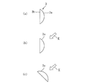
本発明では、容器3の正面部3aまたは背面部3bの形状は、上述した円弧形に限定されるものではなく、幅方向において両側部よりも厚さが大きい部位を有すると共に、正面および背面は共に左右対称形であるのが好ましく、上記関係式、すなわち1≦w/t≦12の関係を有し、かつ容器の正面と背面の形状は合同でないという条件を充足するのがより好ましい。例えば、図7(a)〜(c)に示すように、水平断面が台形の正面部31a、三角形の正面部32a、波形の正面部33aなどであってもよい。
図7(d)は、正面両側にそれぞれリブ15、15を突設したものである。リブ15,15は容器3の縦方向の全長にわたって設けてもよく、一部のみであってもよい。また、リブ15は両側のみに限定されず、複数個所にリブを設けてもよい。これは、一定の幅(長さ)で風を受けることができる表面積を大きくできるためである。
In the present invention, the shape of the
FIG. 7D shows
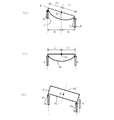
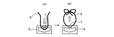
吊り下げ紐5を容器3に取り付ける方法は、図3、図4に示した方法に限定されるものではなく、種々の方法が採用可能である。例えば、図8(a)、(b)に示すように、吊り下げ紐5をフック状の引っ掛け部7に引っ掛け、両端を結ぶようにしてもよい。図8(a)、(b)に示す引っ掛け部7は、容器3の正面部3aまたは背面部3bの上端部を略U字形に切り欠いて形成されているが、これに限定されない。
また、吊り下げ紐5に代えて、図9(a)、(b)に示すような吊り下げ部材5´を用いてもよい。この吊り下げ部材5´には、例えばプラスチック、エラストマー、金属などの線材その他の吊り下げ可能な部材を使用することができる。吊り下げ部材5・は一端に係止部16が設けられ、この係止部16を容器3の上面に設けた孔(図示せず)に挿入し、当該孔に係止させる。吊り下げ部材5・の他端には球形部17が設けられており、この球形部17を容器3の側面上端に設けた凹部18に挿入し、吊り下げ部材5・をループ状に取り付ける。
図8(a)、(b)および図9(a)、(b)に示す吊り下げ紐5や吊り下げ部材5´はいずれも前記した0≦y/x≦2の関係(図3を参照)を有するのが好ましい。
The method of attaching the hanging
Moreover, it may replace with the hanging
8 (a), 8 (b) and FIGS. 9 (a), 9 (b), the hanging
本実施形態の薬剤揮散装置1は、例えば、屋内や屋外に吊り下げて使用する。このようにして用いると、風向きに応じて、容器3は回転して風上を向くので、高い揮散量を得ることができるので、例えば、蚊、蝿等の飛翔害虫が侵入する箇所である建物の出入り口や窓等の開口部にこれを吊り下げると、害虫の防除に効果的である。
また、例えば、トイレや室内の芳香、消臭等を簡便に行うことができる。また、本発明の薬剤揮散装置を、例えば、送風機やファン等の送風手段の前面に配置すると、送風によって常温揮散性薬剤の揮散性をさらに高めることができる。
The chemical volatilization apparatus 1 of the present embodiment is used by being hung indoors or outdoors, for example. When used in this manner, the
In addition, for example, a toilet, indoor aroma, deodorization, and the like can be easily performed. Moreover, when the chemical volatilization device of the present invention is disposed on the front surface of a blowing means such as a blower or a fan, the volatility of the room temperature volatile chemical can be further enhanced by blowing.
以下、容器3の形状について試験を行ったので、その試験結果を具体的に説明するが、本発明は以下の試験例によって何ら限定されるものではない。
Hereinafter, since the test was performed on the shape of the
(試験例)
図10(a)は試験に使用した容器13を示している。この容器13はプラスチック板を筒状に加工したものであり、上下に蓋はない。容器13の正面13aは、表1に示す所定寸法の円弧状であり、背面13bは平坦になっている。正面13aおよび背面13bの開口率(総面積に対する通風開口部の面積の割合)はいずれも10%である。
容器13について、図10(a)に示す寸法w、t、hが異なる仕様の試料No.1〜10を用意した。この容器13を紐5で吊り下げ、これに、図示しない送風機(家庭用の扇風機)から風(矢印Kで示す)を当て、容器13の正面13aまたは背面13bが風の来る方向(風上)に向くか否かを調べた。このとき、送風機を図10(b)に示すように容器13に対して0°、45°、90°、135°の位置に設置し、容器13に向かって風(K)を送った。容器13に当る風速は、1.5m/秒、1.0m/秒および0.5m/秒の3段階で試験を行った。
試験は下記のように評価した。
○:容器13の正面13aまたは背面13bが風の来る方向に向く。
×:容器13が回転して風の来る方向に向かないか、あるいは風で連続して回転する。
(Test example)
FIG. 10A shows the
For the
The test was evaluated as follows.
○: The
X: The
試験結果を表1に示す。

試料No.1、2、5〜10について、さらに以下の点が明らかになる。
(a)容器13に対して風の入射角が0°のとき、容器の正面13a側に立って容器13を平面視した場合において、反時計回りに回転する左回りモーメントが加わり、右回りモーメントが0であるので、容器13は反時計回りに回転して、正面13aが風の来る方向に向く。
(b) 容器13に対して風の来る角度が45°のとき、容器の正面13a側に立って容器13を平面視した場合において、(左回りモーメント)>(右回りモーメント)となるので、容器13は反時計方向に回転して、正面13aが風の来る方向に向く。
(c)容器13に対して風の来る角度が90°のとき、容器の正面13a側に立って容器13を平面視した場合において、左右のモーメントは等しくなるので、容器13は回転せず、容器13の正面13aが風の来る方向に向いたままである。
(d)容器13に対して風の入射角が135°のとき、容器の正面13a側に立って容器13を平面視した場合において、(左回りモーメント)<(右回りモーメント)となるので、容器13は時計方向に回転して、正面13aが風の来る方向に向く。
Sample No. The following points are further clarified for 1, 2, 5 to 10.
(A) When the incident angle of the wind with respect to the
(b) When the angle at which the wind comes to the
(C) When the angle of the wind with respect to the
(D) When the incident angle of the wind with respect to the
また、表1から、容器13が1≦w/t≦12(但し、wは横幅、tは最大厚みである)の関係を有する試料No.1,2,5〜10は、容器13の正面13aが風の来る方向に向き、風速の影響も受けないことが確認された。
一方、試料No.3は、w/tが12を超えるため、特に風速が高い場合に、容器13が回転して、風の来る方向に向かなかった。また、試料No.4は、厚みtが0であるので、左右のモーメントは等しくなり、いずれの角度であっても、特に風速が高いときには、容器13は回転して風の来る方向に向かないか、あるいは風で連続して回転するようになる。
Further, from Table 1, sample Nos. 1, 2, 5 to 10 in which the
On the other hand, since the sample No. 3 has w / t exceeding 12, especially when the wind speed is high, the
なお、以上の実施形態では、正面が円弧状その他の形状を有し、背面が平坦な容器について説明したが、正面が平坦ないしそれに近い形状を有し、背面が円弧状その他の形状を有する容器であっても同様の効果が得られる。 In the above embodiment, a container having a front surface having an arc shape or other shape and a back surface having a flat shape has been described. However, a container having a front surface having a flat shape or a shape close thereto and the back surface having an arc shape or other shape. However, the same effect can be obtained.
1 薬剤揮散装置
2 担体
3 容器
3a 正面部
3b 背面部
3c 上面部
4、4´ 通風開口部
5 吊り下げ紐(吊り下げ具)
5´ 吊り下げ部材(吊り下げ具)
6 空間
8a、8b 挟持部材
9 固定具
10 取付孔
13 容器
15 リブ
16 係止部
17 球形部
18 凹部
DESCRIPTION OF SYMBOLS 1
5 'Hanging member (hanging tool)
6
Claims (7)
前記容器は、正面と背面を有する略板状であり、容器の正面または背面に対する風の入射角が90°であるとき、左右のモーメントが等しくなり、前記風の入射角が90°以外のときは、左右のモーメントが等しくならない形状を有する(但し、左右とは、容器の正面側に立って容器を平面視したときの左右をいう)、ことを特徴とする薬剤揮散装置。 A carrier holding a room temperature volatile chemical, a container containing the carrier inside and having a ventilation opening, and a hanging tool for hanging the container,
The container has a substantially plate shape having a front surface and a rear surface. When the incident angle of the wind with respect to the front or rear surface of the container is 90 °, the left and right moments are equal, and when the incident angle of the wind is other than 90 °. Has a shape in which the left and right moments are not equal (note that left and right are the left and right when the container is viewed in plan while standing on the front side of the container).
Priority Applications (1)
| Application Number | Priority Date | Filing Date | Title |
|---|---|---|---|
| JP2016240695A JP6904693B2 (en) | 2016-12-12 | 2016-12-12 | Chemical volatilizer |
Applications Claiming Priority (1)
| Application Number | Priority Date | Filing Date | Title |
|---|---|---|---|
| JP2016240695A JP6904693B2 (en) | 2016-12-12 | 2016-12-12 | Chemical volatilizer |
Publications (3)
| Publication Number | Publication Date |
|---|---|
| JP2018093778A true JP2018093778A (en) | 2018-06-21 |
| JP2018093778A5 JP2018093778A5 (en) | 2018-12-20 |
| JP6904693B2 JP6904693B2 (en) | 2021-07-21 |
Family
ID=62631873
Family Applications (1)
| Application Number | Title | Priority Date | Filing Date |
|---|---|---|---|
| JP2016240695A Active JP6904693B2 (en) | 2016-12-12 | 2016-12-12 | Chemical volatilizer |
Country Status (1)
| Country | Link |
|---|---|
| JP (1) | JP6904693B2 (en) |
Cited By (1)
| Publication number | Priority date | Publication date | Assignee | Title |
|---|---|---|---|---|
| WO2020166709A1 (en) * | 2019-02-14 | 2020-08-20 | アース製薬株式会社 | Chemical volatilizing device |
Citations (9)
| Publication number | Priority date | Publication date | Assignee | Title |
|---|---|---|---|---|
| JPS5774046U (en) * | 1980-10-22 | 1982-05-07 | ||
| JPS6191228U (en) * | 1984-11-20 | 1986-06-13 | ||
| JPH04136236U (en) * | 1991-06-13 | 1992-12-18 | 株式会社田窪工業所 | aroma generator |
| JP2008214213A (en) * | 2007-03-01 | 2008-09-18 | Sumika Life Tech Co Ltd | Tubular insecticide transpirator |
| JP2010285385A (en) * | 2009-06-12 | 2010-12-24 | Sumitomo Chemical Co Ltd | Tool for controlling insect pest, and method for controlling insect pest |
| WO2013111429A1 (en) * | 2012-01-24 | 2013-08-01 | 村田機械株式会社 | Wind direction and wind speed measurement device |
| US20140158789A1 (en) * | 2012-12-11 | 2014-06-12 | American Covers, Inc. | Membrane air freshener with direct dome lable |
| JP2014135910A (en) * | 2013-01-15 | 2014-07-28 | Fumakilla Ltd | Agent diffuser |
| JP2016054653A (en) * | 2014-09-05 | 2016-04-21 | 大日本除蟲菊株式会社 | Chemical volatilization device |
-
2016
- 2016-12-12 JP JP2016240695A patent/JP6904693B2/en active Active
Patent Citations (9)
| Publication number | Priority date | Publication date | Assignee | Title |
|---|---|---|---|---|
| JPS5774046U (en) * | 1980-10-22 | 1982-05-07 | ||
| JPS6191228U (en) * | 1984-11-20 | 1986-06-13 | ||
| JPH04136236U (en) * | 1991-06-13 | 1992-12-18 | 株式会社田窪工業所 | aroma generator |
| JP2008214213A (en) * | 2007-03-01 | 2008-09-18 | Sumika Life Tech Co Ltd | Tubular insecticide transpirator |
| JP2010285385A (en) * | 2009-06-12 | 2010-12-24 | Sumitomo Chemical Co Ltd | Tool for controlling insect pest, and method for controlling insect pest |
| WO2013111429A1 (en) * | 2012-01-24 | 2013-08-01 | 村田機械株式会社 | Wind direction and wind speed measurement device |
| US20140158789A1 (en) * | 2012-12-11 | 2014-06-12 | American Covers, Inc. | Membrane air freshener with direct dome lable |
| JP2014135910A (en) * | 2013-01-15 | 2014-07-28 | Fumakilla Ltd | Agent diffuser |
| JP2016054653A (en) * | 2014-09-05 | 2016-04-21 | 大日本除蟲菊株式会社 | Chemical volatilization device |
Cited By (1)
| Publication number | Priority date | Publication date | Assignee | Title |
|---|---|---|---|---|
| WO2020166709A1 (en) * | 2019-02-14 | 2020-08-20 | アース製薬株式会社 | Chemical volatilizing device |
Also Published As
| Publication number | Publication date |
|---|---|
| JP6904693B2 (en) | 2021-07-21 |
Similar Documents
| Publication | Publication Date | Title |
|---|---|---|
| US7790000B2 (en) | Volatilizer | |
| JP5647003B2 (en) | Transpiration material | |
| AU2013335918B2 (en) | Chemical volatilization body | |
| JP5556790B2 (en) | Composition in which light / ultraviolet light deterioration of pyrethroid compound is prevented and method for preventing light / ultraviolet light deterioration | |
| JP6904693B2 (en) | Chemical volatilizer | |
| JP2009131243A (en) | Pest control device | |
| JP5718143B2 (en) | Transpiration material | |
| JP2604239B2 (en) | Liquid absorption wick and chemical evaporation method | |
| JP5385501B2 (en) | Transpiration material, pre-sucking action reducing agent for blood-sucking pests, and method | |
| JP7477830B2 (en) | Chemical volatilization device | |
| JP7188980B2 (en) | Transfluthrin volatilization promotion method, transfluthrin volatilization accelerator, and drug volatilization composition | |
| WO2020166709A1 (en) | Chemical volatilizing device | |
| JP2001103899A (en) | Device for diffusing chemical agent | |
| JP5948010B2 (en) | Chemical vaporizer to prevent cockroach invasion | |
| JP5879033B2 (en) | Air curtain device | |
| JP7485583B2 (en) | Drug volatilization device and drug volatilization method | |
| JP2008178336A (en) | Method for controlling insect pest | |
| JP2005126393A (en) | Aroma-releasing and insect-proofing product | |
| JP2010017195A (en) | Apparatus for volatilizing chemical | |
| JP2000247806A (en) | Chemical diffusion and chemical diffuser therefor | |
| JP2024052192A (en) | Chemical volatilization device | |
| JP2018038277A (en) | Chemical volatilization body and volatilization method | |
| JP2006166745A (en) | Method for controlling landing of insect pest, volatilization apparatus and volatile preparation | |
| JP6348091B2 (en) | Chemical vaporizer to prevent cockroach invasion | |
| JP2005318801A (en) | Apparatus for volatilizing chemical |
Legal Events
| Date | Code | Title | Description |
|---|---|---|---|
| A521 | Request for written amendment filed |
Free format text: JAPANESE INTERMEDIATE CODE: A523 Effective date: 20181107 |
|
| A621 | Written request for application examination |
Free format text: JAPANESE INTERMEDIATE CODE: A621 Effective date: 20190925 |
|
| A977 | Report on retrieval |
Free format text: JAPANESE INTERMEDIATE CODE: A971007 Effective date: 20200813 |
|
| A131 | Notification of reasons for refusal |
Free format text: JAPANESE INTERMEDIATE CODE: A131 Effective date: 20200901 |
|
| A521 | Request for written amendment filed |
Free format text: JAPANESE INTERMEDIATE CODE: A523 Effective date: 20201030 |
|
| A02 | Decision of refusal |
Free format text: JAPANESE INTERMEDIATE CODE: A02 Effective date: 20201124 |
|
| A521 | Request for written amendment filed |
Free format text: JAPANESE INTERMEDIATE CODE: A523 Effective date: 20210222 |
|
| C60 | Trial request (containing other claim documents, opposition documents) |
Free format text: JAPANESE INTERMEDIATE CODE: C60 Effective date: 20210222 |
|
| C11 | Written invitation by the commissioner to file amendments |
Free format text: JAPANESE INTERMEDIATE CODE: C11 Effective date: 20210309 |
|
| A521 | Request for written amendment filed |
Free format text: JAPANESE INTERMEDIATE CODE: A523 Effective date: 20210406 |
|
| A911 | Transfer to examiner for re-examination before appeal (zenchi) |
Free format text: JAPANESE INTERMEDIATE CODE: A911 Effective date: 20210407 |
|
| C21 | Notice of transfer of a case for reconsideration by examiners before appeal proceedings |
Free format text: JAPANESE INTERMEDIATE CODE: C21 Effective date: 20210413 |
|
| TRDD | Decision of grant or rejection written | ||
| A01 | Written decision to grant a patent or to grant a registration (utility model) |
Free format text: JAPANESE INTERMEDIATE CODE: A01 Effective date: 20210616 |
|
| A61 | First payment of annual fees (during grant procedure) |
Free format text: JAPANESE INTERMEDIATE CODE: A61 Effective date: 20210624 |
|
| R150 | Certificate of patent or registration of utility model |
Ref document number: 6904693 Country of ref document: JP Free format text: JAPANESE INTERMEDIATE CODE: R150 |
|
| R250 | Receipt of annual fees |
Free format text: JAPANESE INTERMEDIATE CODE: R250 |