JP2018091663A - Gas detector - Google Patents
Gas detector Download PDFInfo
- Publication number
- JP2018091663A JP2018091663A JP2016233384A JP2016233384A JP2018091663A JP 2018091663 A JP2018091663 A JP 2018091663A JP 2016233384 A JP2016233384 A JP 2016233384A JP 2016233384 A JP2016233384 A JP 2016233384A JP 2018091663 A JP2018091663 A JP 2018091663A
- Authority
- JP
- Japan
- Prior art keywords
- voltage
- current
- electrode
- concentration
- output current
- Prior art date
- Legal status (The legal status is an assumption and is not a legal conclusion. Google has not performed a legal analysis and makes no representation as to the accuracy of the status listed.)
- Pending
Links
Images

Classifications
-
- G—PHYSICS
- G01—MEASURING; TESTING
- G01N—INVESTIGATING OR ANALYSING MATERIALS BY DETERMINING THEIR CHEMICAL OR PHYSICAL PROPERTIES
- G01N27/00—Investigating or analysing materials by the use of electric, electrochemical, or magnetic means
- G01N27/26—Investigating or analysing materials by the use of electric, electrochemical, or magnetic means by investigating electrochemical variables; by using electrolysis or electrophoresis
- G01N27/403—Cells and electrode assemblies
- G01N27/406—Cells and probes with solid electrolytes
- G01N27/407—Cells and probes with solid electrolytes for investigating or analysing gases
- G01N27/4073—Composition or fabrication of the solid electrolyte
- G01N27/4074—Composition or fabrication of the solid electrolyte for detection of gases other than oxygen
-
- G—PHYSICS
- G01—MEASURING; TESTING
- G01N—INVESTIGATING OR ANALYSING MATERIALS BY DETERMINING THEIR CHEMICAL OR PHYSICAL PROPERTIES
- G01N27/00—Investigating or analysing materials by the use of electric, electrochemical, or magnetic means
- G01N27/26—Investigating or analysing materials by the use of electric, electrochemical, or magnetic means by investigating electrochemical variables; by using electrolysis or electrophoresis
- G01N27/416—Systems
- G01N27/48—Systems using polarography, i.e. measuring changes in current under a slowly-varying voltage
-
- G—PHYSICS
- G01—MEASURING; TESTING
- G01M—TESTING STATIC OR DYNAMIC BALANCE OF MACHINES OR STRUCTURES; TESTING OF STRUCTURES OR APPARATUS, NOT OTHERWISE PROVIDED FOR
- G01M15/00—Testing of engines
- G01M15/04—Testing internal-combustion engines
- G01M15/10—Testing internal-combustion engines by monitoring exhaust gases or combustion flame
- G01M15/102—Testing internal-combustion engines by monitoring exhaust gases or combustion flame by monitoring exhaust gases
-
- G—PHYSICS
- G01—MEASURING; TESTING
- G01N—INVESTIGATING OR ANALYSING MATERIALS BY DETERMINING THEIR CHEMICAL OR PHYSICAL PROPERTIES
- G01N27/00—Investigating or analysing materials by the use of electric, electrochemical, or magnetic means
- G01N27/26—Investigating or analysing materials by the use of electric, electrochemical, or magnetic means by investigating electrochemical variables; by using electrolysis or electrophoresis
- G01N27/403—Cells and electrode assemblies
- G01N27/406—Cells and probes with solid electrolytes
- G01N27/4065—Circuit arrangements specially adapted therefor
-
- G—PHYSICS
- G01—MEASURING; TESTING
- G01N—INVESTIGATING OR ANALYSING MATERIALS BY DETERMINING THEIR CHEMICAL OR PHYSICAL PROPERTIES
- G01N27/00—Investigating or analysing materials by the use of electric, electrochemical, or magnetic means
- G01N27/26—Investigating or analysing materials by the use of electric, electrochemical, or magnetic means by investigating electrochemical variables; by using electrolysis or electrophoresis
- G01N27/403—Cells and electrode assemblies
- G01N27/406—Cells and probes with solid electrolytes
- G01N27/4067—Means for heating or controlling the temperature of the solid electrolyte
-
- G—PHYSICS
- G01—MEASURING; TESTING
- G01N—INVESTIGATING OR ANALYSING MATERIALS BY DETERMINING THEIR CHEMICAL OR PHYSICAL PROPERTIES
- G01N27/00—Investigating or analysing materials by the use of electric, electrochemical, or magnetic means
- G01N27/26—Investigating or analysing materials by the use of electric, electrochemical, or magnetic means by investigating electrochemical variables; by using electrolysis or electrophoresis
- G01N27/403—Cells and electrode assemblies
- G01N27/406—Cells and probes with solid electrolytes
- G01N27/407—Cells and probes with solid electrolytes for investigating or analysing gases
- G01N27/409—Oxygen concentration cells
-
- G—PHYSICS
- G01—MEASURING; TESTING
- G01N—INVESTIGATING OR ANALYSING MATERIALS BY DETERMINING THEIR CHEMICAL OR PHYSICAL PROPERTIES
- G01N27/00—Investigating or analysing materials by the use of electric, electrochemical, or magnetic means
- G01N27/26—Investigating or analysing materials by the use of electric, electrochemical, or magnetic means by investigating electrochemical variables; by using electrolysis or electrophoresis
- G01N27/403—Cells and electrode assemblies
- G01N27/406—Cells and probes with solid electrolytes
- G01N27/407—Cells and probes with solid electrolytes for investigating or analysing gases
- G01N27/41—Oxygen pumping cells
-
- G—PHYSICS
- G01—MEASURING; TESTING
- G01N—INVESTIGATING OR ANALYSING MATERIALS BY DETERMINING THEIR CHEMICAL OR PHYSICAL PROPERTIES
- G01N27/00—Investigating or analysing materials by the use of electric, electrochemical, or magnetic means
- G01N27/26—Investigating or analysing materials by the use of electric, electrochemical, or magnetic means by investigating electrochemical variables; by using electrolysis or electrophoresis
- G01N27/416—Systems
- G01N27/417—Systems using cells, i.e. more than one cell and probes with solid electrolytes
- G01N27/419—Measuring voltages or currents with a combination of oxygen pumping cells and oxygen concentration cells
-
- G—PHYSICS
- G01—MEASURING; TESTING
- G01N—INVESTIGATING OR ANALYSING MATERIALS BY DETERMINING THEIR CHEMICAL OR PHYSICAL PROPERTIES
- G01N33/00—Investigating or analysing materials by specific methods not covered by groups G01N1/00 - G01N31/00
- G01N33/0004—Gaseous mixtures, e.g. polluted air
- G01N33/0009—General constructional details of gas analysers, e.g. portable test equipment
- G01N33/0027—General constructional details of gas analysers, e.g. portable test equipment concerning the detector
- G01N33/0036—General constructional details of gas analysers, e.g. portable test equipment concerning the detector specially adapted to detect a particular component
- G01N33/0042—SO2 or SO3
-
- Y—GENERAL TAGGING OF NEW TECHNOLOGICAL DEVELOPMENTS; GENERAL TAGGING OF CROSS-SECTIONAL TECHNOLOGIES SPANNING OVER SEVERAL SECTIONS OF THE IPC; TECHNICAL SUBJECTS COVERED BY FORMER USPC CROSS-REFERENCE ART COLLECTIONS [XRACs] AND DIGESTS
- Y02—TECHNOLOGIES OR APPLICATIONS FOR MITIGATION OR ADAPTATION AGAINST CLIMATE CHANGE
- Y02A—TECHNOLOGIES FOR ADAPTATION TO CLIMATE CHANGE
- Y02A50/00—TECHNOLOGIES FOR ADAPTATION TO CLIMATE CHANGE in human health protection, e.g. against extreme weather
- Y02A50/20—Air quality improvement or preservation, e.g. vehicle emission control or emission reduction by using catalytic converters
Landscapes
- Chemical & Material Sciences (AREA)
- Life Sciences & Earth Sciences (AREA)
- Health & Medical Sciences (AREA)
- Physics & Mathematics (AREA)
- General Physics & Mathematics (AREA)
- Pathology (AREA)
- Immunology (AREA)
- Analytical Chemistry (AREA)
- Biochemistry (AREA)
- General Health & Medical Sciences (AREA)
- Molecular Biology (AREA)
- Chemical Kinetics & Catalysis (AREA)
- Electrochemistry (AREA)
- Engineering & Computer Science (AREA)
- Combustion & Propulsion (AREA)
- Food Science & Technology (AREA)
- Medicinal Chemistry (AREA)
- Exhaust Gas After Treatment (AREA)
- Combined Controls Of Internal Combustion Engines (AREA)
Abstract
【課題】内燃機関の排出する排気中に含まれる所定濃度以上の硫黄酸化物の有無の判定又は濃度を検出することが可能なガス検出装置を提供する。【解決手段】ガス検出装置は、電圧印加部81を制御すると共に電気化学セル41cの第1電極41aと第2電極41bとの間に流れる出力電流を取得する測定制御部を備える。測定制御部は、降圧スイープ中であって印加電圧が硫黄酸化物の分解開始電圧以下の範囲になっている期間の出力電流に相関する値を、第1電流として取得し、出力電流が酸素の限界電流となる電圧以上の特定電圧に印加電圧がなっている時点において検出される出力電流であり且つ昇圧スイープによって第1電極に付着した硫黄が当該第1電極において再酸化反応することに起因する電流を含まない当該出力電流を、第2電流として取得する。測定制御部は、第2電流と第1電流との差分を用いて、排気中の硫黄酸化物濃度の検出を行う。【選択図】図2The present invention provides a gas detection device capable of determining whether or not sulfur oxide having a predetermined concentration or more contained in exhaust gas discharged from an internal combustion engine is present or detecting the concentration. A gas detection apparatus includes a measurement control unit that controls a voltage application unit 81 and acquires an output current flowing between a first electrode 41a and a second electrode 41b of an electrochemical cell 41c. The measurement control unit obtains, as the first current, a value that correlates with the output current during the step-down sweep and the applied voltage is in the range of the sulfur oxide decomposition start voltage or less, and the output current is oxygen. This is an output current detected when the applied voltage is at a specific voltage that is equal to or higher than the voltage that becomes the limit current, and is caused by the re-oxidation reaction of sulfur that has adhered to the first electrode due to the boosting sweep at the first electrode. The output current not including the current is acquired as the second current. The measurement control unit detects the sulfur oxide concentration in the exhaust gas using the difference between the second current and the first current. [Selection] Figure 2
Description
本発明は、内燃機関の排出する排気(被検ガス)中に含まれる所定濃度以上の硫黄酸化物の有無の判定又はその排気中に含まれる硫黄酸化物の濃度を検出することが可能なガス検出装置に関する。 The present invention is a gas capable of determining the presence or absence of sulfur oxides of a predetermined concentration or higher contained in exhaust gas (test gas) discharged from an internal combustion engine or detecting the concentration of sulfur oxides contained in the exhaust gas. The present invention relates to a detection device.
従来から、内燃機関を制御するために、排気中に含まれる酸素(O2)の濃度に基づいて燃焼室内の混合気の空燃比(A/F)を取得する空燃比センサ(「A/Fセンサ」とも称呼される。)が広く使用されている。このような空燃比センサの1つのタイプとして、限界電流式ガスセンサを挙げることができる。 Conventionally, in order to control an internal combustion engine, an air-fuel ratio sensor (“A / F”) that acquires an air-fuel ratio (A / F) of an air-fuel mixture in a combustion chamber based on a concentration of oxygen (O 2 ) contained in exhaust gas. Also referred to as "sensor") is widely used. One type of such an air-fuel ratio sensor is a limiting current type gas sensor.
更に、このような限界電流式ガスセンサを用いて、排気中の硫黄酸化物(以下、「SOx」と称呼される場合がある。)の濃度を検出するSOx濃度検出装置(以下、「従来装置」と称呼する。)が提案されている(例えば、特許文献1を参照。)。
Furthermore, an SOx concentration detection device (hereinafter referred to as “conventional device”) for detecting the concentration of sulfur oxide (hereinafter sometimes referred to as “SOx”) in exhaust gas using such a limiting current type gas sensor. (Refer to
従来装置は、酸素イオン伝導性固体電解質の酸素ポンピング作用を利用したセンシングセル(電気化学セル)を含む。従来装置は、センシングセルの一対の電極間に電圧を印加することにより、排気中の酸素原子を含むガス成分(例えばO2、SOx及びH2O等であり、以下、「酸素含有成分」とも称呼する。)を分解させ、それによって、酸化物イオン(O2−)を発生させる。従来装置は、酸素含有成分の分解によって生じた酸化物イオンがセンシングセルの電極間を移動すること(酸素ポンピング作用)によって当該電極間を流れる電流の特性を、検出するようになっている。 The conventional apparatus includes a sensing cell (electrochemical cell) that utilizes the oxygen pumping action of an oxygen ion conductive solid electrolyte. A conventional apparatus is a gas component containing oxygen atoms in exhaust gas (for example, O 2 , SOx, H 2 O, etc.) by applying a voltage between a pair of electrodes of a sensing cell, hereinafter referred to as “oxygen-containing component”. Is called), thereby generating oxide ions (O 2− ). The conventional apparatus detects the characteristic of the current flowing between the electrodes by the movement of oxide ions generated by the decomposition of the oxygen-containing component between the electrodes of the sensing cell (oxygen pumping action).
より具体的に述べると、従来装置は、SOx濃度を検出するときに、印加電圧スイープを実行するようになっている。即ち、従来装置は、センシングセルに対して印可する印可電圧を0.4Vから0.8Vまで昇圧した後、0.8Vから0.4Vまで降圧する印加電圧スイープを、実行するようになっている。 More specifically, the conventional apparatus performs an applied voltage sweep when detecting the SOx concentration. In other words, the conventional apparatus performs an applied voltage sweep in which the applied voltage applied to the sensing cell is increased from 0.4 V to 0.8 V and then decreased from 0.8 V to 0.4 V. .
そして、従来装置は、印可電圧が0.8Vに達した時点の「センシングセルの電極間を流れる電流(以下、「電極電流」又は「出力電流」と称呼する場合がある。)」である参照電流と、印加電圧が0.8Vから0.4Vまで低下させられている期間における出力電流の最小値であるピーク値との差を用いて、SOx濃度を算出するようになっている。 In the conventional apparatus, the reference is “current flowing between electrodes of the sensing cell (hereinafter sometimes referred to as“ electrode current ”or“ output current ”)” when the applied voltage reaches 0.8V. The SOx concentration is calculated using the difference between the current and the peak value which is the minimum value of the output current during the period when the applied voltage is lowered from 0.8V to 0.4V.
しかしながら、上記出力電流は、排気中に含まれるSOx以外の酸素含有成分の影響によっても変化してしまう可能性が高い。例えば、水(H2O)の分解電圧は硫黄酸化物の分解電圧と同じ程度であるか、或いはそれより僅かに高い。更に、排気中の水の濃度は例えば、混合気の空燃比に応じて変動する。このため、水の分解に起因する出力電流への影響を取り除いて、SOx成分の分解のみに起因する出力電流を検出することは困難である。従って、「SOx以外の酸素含有成分の影響を受けることがなく、且つ、SOx成分のみに起因する出力電流変化」を用いて、排気中に所定濃度以上の硫黄酸化物が存在するか否かの判定又は排気中の硫黄酸化物の濃度を検出することが求められていた。 However, the output current is likely to change due to the influence of oxygen-containing components other than SOx contained in the exhaust gas. For example, the decomposition voltage of water (H 2 O) is about the same as or slightly higher than the decomposition voltage of sulfur oxide. Furthermore, the concentration of water in the exhaust gas varies depending on the air-fuel ratio of the air-fuel mixture, for example. For this reason, it is difficult to remove the influence on the output current caused by the decomposition of water and detect the output current caused only by the decomposition of the SOx component. Therefore, whether or not there is a sulfur oxide of a predetermined concentration or more in the exhaust gas using the “change in output current that is not affected by oxygen-containing components other than SOx and is caused only by the SOx component”. It has been desired to determine or detect the concentration of sulfur oxide in the exhaust.
本発明は上述した課題に対処するためになされた。即ち、本発明の目的の一つは、排気中に所定濃度以上の硫黄酸化物が含まれているか否かの判定又は排気中の硫黄酸化物の濃度を精度よく行うことができるガス検出装置(以下、「本発明検出装置」とも称呼する。)を提供することにある。 The present invention has been made to address the above-described problems. That is, one of the objects of the present invention is to provide a gas detection device (determining whether or not sulfur oxide at a predetermined concentration or more is contained in the exhaust gas or accurately determining the concentration of sulfur oxide in the exhaust gas ( Hereinafter, it is also referred to as “the detection device of the present invention”).
本発明検出装置は、内燃機関の排気通路(12)に設けられ、酸化物イオン伝導性を有する固体電解質体(41s)と前記固体電解質体の表面にそれぞれ形成された第1電極(41a)及び第2電極(41b)とを含む電気化学セル(41c)と、前記排気通路を流れる排気が通過可能な多孔質材料からなる拡散抵抗体(61)とを備え、前記排気通路を流れる排気が前記拡散抵抗体を通して前記第1電極に到達するように構成された素子部(40)と、
前記第1電極と前記第2電極との間に電圧を印加する電圧印加部(81)と、
前記第1電極と前記第2電極との間に流れる電流である出力電流(Im)を検出する電流検出部(91)と、
前記電圧印加部を用いて前記第1電極と前記第2電極との間に印加される電圧である印加電圧(Vm)を制御すると共に前記電流検出部により検出される出力電流に基づいて、前記排気中に所定濃度以上の硫黄酸化物が含まれているか否かの判定又は前記排気中の硫黄酸化物の濃度の検出を行う測定制御部(20)と
を有し、
前記測定制御部は、
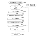
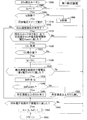
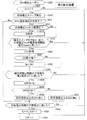
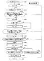
前記内燃機関に供給される混合気の空燃比(A/F)が安定している状態である場合(図9のステップ930での「Yes」との判定)、前記電圧印加部を用いて前記印加電圧を、前記出力電流が酸素の限界電流となる第1電圧であって且つ硫黄酸化物の分解開始電圧未満である第1電圧以上であり且つ硫黄酸化物の分解開始電圧未満である所定電圧から、硫黄酸化物の分解開始電圧よりも高い第2電圧まで、上昇させる昇圧スイープを実行した後、前記第2電圧から前記第1電圧まで所定の降圧速度にて下降させる降圧スイープを実行し(図10のステップ1010)、且つ、
前記降圧スイープ中に前記印加電圧が硫黄酸化物の分解開始電圧未満となったときに前記第1電極に吸着していた硫黄が当該第1電極において再酸化反応して硫黄酸化物へと戻ることにより前記第1電極と前記第2電極との間に流れる電流に起因して前記出力電流に生じる変化であって前記排気に含まれる前記硫黄酸化物の濃度が高いほど大きくなる出力電流に生じる変化の程度、に相関を有するパラメータ(Idiff)を前記電流検出部により検出される出力電流に基づいて取得し(図10及び図12のそれぞれに示されたステップ1038、図14のステップ1450、図15及び図16のそれぞれに示されたステップ1038、図17のステップ1450)、当該パラメータに基づいて前記排気中に所定濃度以上の硫黄酸化物が含まれているか否かの判定(図10及び図12のそれそれに示されたステップ1040、図14のステップ1460)又は前記排気中の硫黄酸化物の濃度の検出を行う(図15のステップ1510、図16のステップ1610、図17のステップ1710)、
ように構成されている。
更に、前記所定の降圧速度が、
前記印加電圧が硫黄酸化物の分解開始電圧未満であって前記第1電圧よりも高い電圧範囲内の電圧となった時点を境に前記再酸化反応の速度(再酸化反応の発生頻度と言うこともできる。)が急増する速度となるように設定される。
加えて、前記測定制御部が、
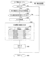
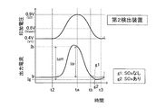
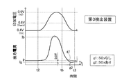
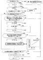
前記降圧スイープ中であって前記印加電圧が前記第1電圧より高く硫黄酸化物の分解開始電圧以下の範囲になっている期間の前記出力電流に相関を有する値を、当該期間において前記電流検出部により検出される出力電流に基づいて第1電流(Ig)として取得し(図10及び図12のそれぞれに示されたステップ1030、図14のステップ1420、図15及び図16のそれぞれに示されたステップ1030、図17のステップ1420)、
前記出力電流が前記酸素の限界電流となる電圧以上の特定電圧に前記印加電圧がなっている時点において前記電流検出部により検出される出力電流であり且つ前記昇圧スイープによって前記第1電極に付着した硫黄が当該第1電極において再酸化反応することに起因する電流を含まない当該出力電流を、第2電流(Ib)として取得し(図10のステップ1009、図12のステップ1214、図14のステップ1440、図15のステップ1009、図16のステップ1214、図17のステップ1440)、
前記取得した第2電流と前記取得した第1電流との差分(Idiff)を算出し(図10及び図12のそれぞれに示されたステップ1038、図14のステップ1450、図15及び図16のそれぞれに示されたステップ1038、図17のステップ1450)、当該差分を、前記パラメータとして用いる(図10及び図12のそれぞれに示されたステップ1040、図14のステップ1460、図15のステップ1510、図16のステップ1610、図17のステップ1710)ように構成されている。
The detection device of the present invention is provided in an exhaust passage (12) of an internal combustion engine, and has a solid electrolyte body (41s) having oxide ion conductivity, a first electrode (41a) formed on the surface of the solid electrolyte body, and An electrochemical cell (41c) including a second electrode (41b), and a diffusion resistor (61) made of a porous material through which the exhaust flowing through the exhaust passage can pass, and the exhaust flowing through the exhaust passage is An element portion (40) configured to reach the first electrode through a diffusion resistor;
A voltage application unit (81) for applying a voltage between the first electrode and the second electrode;
A current detector (91) that detects an output current (Im) that is a current flowing between the first electrode and the second electrode;
Based on an output current detected by the current detector while controlling an applied voltage (Vm), which is a voltage applied between the first electrode and the second electrode, using the voltage application unit, A measurement control unit (20) for determining whether or not sulfur oxide of a predetermined concentration or more is contained in the exhaust or detecting the concentration of sulfur oxide in the exhaust, and
The measurement control unit
When the air-fuel ratio (A / F) of the air-fuel mixture supplied to the internal combustion engine is in a stable state (determination of “Yes” in
During the step-down sweep, when the applied voltage becomes less than the decomposition start voltage of sulfur oxide, sulfur adsorbed on the first electrode is reoxidized at the first electrode and returns to sulfur oxide. Due to the current flowing between the first electrode and the second electrode, the change that occurs in the output current, and the change that occurs in the output current that increases as the concentration of the sulfur oxide contained in the exhaust gas increases Is obtained based on the output current detected by the current detector (
It is configured as follows.
Further, the predetermined step-down speed is
The rate of the reoxidation reaction (referred to as the frequency of occurrence of the reoxidation reaction) when the applied voltage is less than the sulfur oxide decomposition start voltage and becomes a voltage within the voltage range higher than the first voltage. Is set so as to increase rapidly.
In addition, the measurement control unit
A value having a correlation with the output current during a period in which the applied voltage is higher than the first voltage and not higher than the decomposition start voltage of sulfur oxide during the step-down sweep, and the current detection unit in the period Is obtained as a first current (Ig) based on the output current detected by (
The output current is an output current detected by the current detection unit at the time when the applied voltage is at a specific voltage that is equal to or higher than a voltage that becomes a limit current of the oxygen, and is attached to the first electrode by the boost sweep. The output current not including the current resulting from the reoxidation reaction of sulfur at the first electrode is acquired as the second current (Ib) (
The difference (Idiff) between the acquired second current and the acquired first current is calculated (
発明者の検討によれば、「降圧スイープを行っているときに第1電極に吸着した硫黄」が当該第1電極において再酸化反応して硫黄酸化物へ戻ることに起因して「硫黄酸化物以外の酸素含有成分」の影響を受け難い「出力電流の変化」が生じることが判明した。更に、降圧スイープにおける所定の経過時間当たりの電圧降下量(即ち、降圧速度)により、この「出力電流の変化」の程度が大きく変わることが判明した(図5(A)及び(B)を参照。)。これらの現象が生じるメカニズムは、次のようなことであると推定される。 According to the inventors' investigation, “sulfur oxide adsorbed on the first electrode during the step-down sweep” is caused to re-oxidize and return to sulfur oxide at the first electrode. It was found that an “output current change” that is hardly affected by “oxygen-containing components other than” occurs. Furthermore, it has been found that the degree of this “change in output current” varies greatly depending on the voltage drop amount (ie, step-down speed) per predetermined elapsed time in the step-down sweep (see FIGS. 5A and 5B). .) The mechanism by which these phenomena occur is presumed to be as follows.
即ち、昇圧スイープを行うことにより第1電極に吸着した硫黄(硫黄酸化物の分解物)が、降圧スイープを行っているときに、当該第1電極において再酸化反応して硫黄酸化物へと戻る。昇圧スイープを行った場合に硫黄酸化物以外の酸素含有成分の分解物(例えば、水の分解物である水素)は第1電極に吸着しないため、降圧スイープを行っているとき、硫黄酸化物以外の酸素含有成分の分解物が当該第1電極において再酸化反応して酸素含有成分へ戻る現象は実質的に生じない。 That is, sulfur (decomposed product of sulfur oxide) adsorbed on the first electrode by performing the pressure-up sweep returns to sulfur oxide by re-oxidation reaction at the first electrode during the pressure-down sweep. . When a pressure sweep is performed, decomposition products of oxygen-containing components other than sulfur oxides (for example, hydrogen, which is a decomposition product of water) do not adsorb to the first electrode. The phenomenon in which the decomposition product of the oxygen-containing component is re-oxidized at the first electrode to return to the oxygen-containing component does not substantially occur.
このため、降圧スイープを行っているときに第1電極に吸着していた硫黄が当該第1電極において再酸化反応して硫黄酸化物へと戻ることにより生じる「出力電流の変化」は、硫黄酸化物以外の酸素含有成分の影響を受けにくい。即ち、降圧スイープ中に硫黄酸化物以外の酸素含有成分の影響を受けにくい「出力電流の変化」が生じる。 For this reason, the "change in output current" that occurs when sulfur adsorbed on the first electrode during the step-down sweep is reoxidized and returned to sulfur oxide at the first electrode is the sulfur oxidation. Not easily affected by oxygen-containing components other than products. That is, during the step-down sweep, an “output current change” that is not easily affected by oxygen-containing components other than sulfur oxides occurs.
ところが、降圧スイープの降圧速度(掃引速度)がある速度より遅い場合、降圧スイープを行っているときに硫黄の再酸化反応が連続的且つ徐々に進行するため、硫黄酸化物濃度がどのような濃度であっても「出力電流の変化」の程度が現れ難い。 However, when the pressure drop speed (sweep speed) of the pressure drop sweep is slower than a certain speed, the sulfur reoxidation reaction proceeds continuously and gradually during the pressure drop sweep. Even so, the degree of “change in output current” hardly appears.
これに対して、降圧スイープの降圧速度をある速度より速くした場合、降圧スイープを行っているときに硫黄の再酸反応がそれ程進行しないまま印加電圧が低下し、印加電圧が「硫黄の再酸化反応が活発になるある電圧範囲(即ち、硫黄酸化物の分解開始電圧未満の所定の電圧範囲)」内の電圧になると、硫黄の再酸化反応が急激に進行する(硫黄の再酸化反応の速度が急増する、硫黄の再酸化反応の発生頻度が急増する)ので、硫黄酸化物濃度が高いほど出力電流の変化の程度が大きくなる。即ち、硫黄酸化物濃度を精度よく検出するのに有意な電流変化が現れる。 On the other hand, when the step-down speed of the step-down sweep is made higher than a certain speed, the applied voltage is lowered while the re-oxidation reaction of sulfur is not progressing so much during the step-down sweep, and the applied voltage becomes “reoxidation of sulfur. When the voltage is within a certain voltage range in which the reaction becomes active (that is, a predetermined voltage range lower than the sulfur oxide decomposition start voltage), the sulfur reoxidation reaction proceeds rapidly (the rate of sulfur reoxidation reaction). As the sulfur oxide concentration increases, the degree of change in the output current increases. That is, a significant current change appears to detect the sulfur oxide concentration with high accuracy.
そこで、本発明検出装置においては、降圧スイープの降圧速度が「印加電圧が硫黄酸化物の分解開始電圧未満であって第1電圧よりも高い電圧範囲内の電圧となった時点を境に硫黄の再酸化反応の速度が急増する速度」となるように設定されている。従って、硫黄酸化物以外の酸素含有成分の影響を受けない出力電流の変化が、硫黄酸化物濃度が高いほど大きく現れる。 Therefore, in the detection device of the present invention, the step-down sweep step-down speed is “the applied voltage is less than the sulfur oxide decomposition start voltage and the voltage in the voltage range higher than the first voltage is the boundary. It is set to be “the rate at which the rate of reoxidation increases rapidly”. Therefore, a change in the output current that is not affected by oxygen-containing components other than sulfur oxide appears more greatly as the sulfur oxide concentration is higher.
更に、本発明検出装置は、そのような硫黄の再酸化反応に起因して「出力電流に生じる変化の程度」に相関を有するパラメータを出力電流に基づいて取得し、そのパラメータに基づいて、排気中に所定濃度以上の硫黄酸化物が含まれているか否かの判定又は排気中の硫黄酸化物の濃度の検出を行うように構成されている。 Furthermore, the detection device of the present invention acquires a parameter having a correlation with “the degree of change in the output current” due to such sulfur reoxidation reaction based on the output current, and based on the parameter, the exhaust gas is exhausted. It is configured to determine whether or not sulfur oxide at a predetermined concentration or more is contained therein or to detect the concentration of sulfur oxide in the exhaust.
更に、本発明検出装置は、再酸化電流変化を表す上記パラメータとして、上記第2電流と上記第1電流との差分(Idiff)を採用している。上記第1電流は、排気中の酸素濃度に応じて変化し、且つ、排気中の硫黄酸化物の濃度が大きくなるほど小さくなる特性を有する。上記第2電流は、排気中の酸素濃度に応じて変化し、且つ、排気中の硫黄酸化物の濃度によって、変化が生じない特性を有する。即ち、上記第2電流の大きさは、排気中の硫黄酸化物の濃度に関わらず同じである。 Furthermore, the detection device of the present invention employs a difference (Idiff) between the second current and the first current as the parameter representing the reoxidation current change. The first current has a characteristic that changes according to the oxygen concentration in the exhaust gas and decreases as the concentration of sulfur oxide in the exhaust gas increases. The second current has a characteristic that changes according to the oxygen concentration in the exhaust gas and does not change depending on the concentration of sulfur oxide in the exhaust gas. That is, the magnitude of the second current is the same regardless of the concentration of sulfur oxide in the exhaust.
排気中の硫黄酸化物の濃度に関わらず第2電流の大きさは同じであるのに対して、排気中の硫黄酸化物の濃度が大きくなるほど、再酸化電流変化の程度は顕著になって第1電流は小さくなるため、排気中の硫黄酸化物の濃度が大きくなるほど、差分Idiffの大きさも大きくなる。加えて、第1電流は排気中の酸素濃度の影響を受けて変化するが、その影響度合いは第2電流にも同じように現れている。従って、差分Idiffは、排気中の酸素濃度(機関の空燃比A/F)の影響を受けることなく、硫黄酸化物の濃度を精度よく表すパラメータとなる。 The magnitude of the second current is the same regardless of the concentration of sulfur oxide in the exhaust, whereas the degree of change in the reoxidation current becomes more pronounced as the concentration of sulfur oxide in the exhaust increases. Since 1 current becomes small, the magnitude of the difference Idiff increases as the concentration of sulfur oxide in the exhaust gas increases. In addition, the first current changes under the influence of the oxygen concentration in the exhaust gas, but the degree of influence also appears in the second current. Therefore, the difference Idiff is a parameter that accurately represents the concentration of sulfur oxide without being affected by the oxygen concentration in the exhaust gas (air-fuel ratio A / F of the engine).
本発明検出装置は、このパラメータ(上記差分(Idiff))を用いて、排気中に所定濃度以上の硫黄酸化物が含まれているか否かの判定又は排気中の硫黄酸化物の濃度の検出を行うので、そのような「判定又は濃度の検出」をより精度良く行うことができる。 The detection device of the present invention uses this parameter (the above difference (Idiff)) to determine whether or not the exhaust gas contains sulfur oxide of a predetermined concentration or more, or to detect the concentration of sulfur oxide in the exhaust gas. Therefore, such “determination or concentration detection” can be performed with higher accuracy.
本発明検出装置の一態様において、
前記測定制御部は、前記排気中に所定濃度以上の硫黄酸化物が含まれているか否かの前記判定を行うように構成されており、
前記測定制御部は、
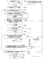
前記差分の大きさが所定の閾値(Idth)以上であるか否かを判定し(図10及び図12のそれぞれに示されたステップ1040、図14のステップ1460)、
前記差分の大きさが前記閾値以上であると判定した場合(図10及び図12のそれぞれに示されたステップ1040での「Yes」との判定、図14のステップ1460での「Yes」との判定)、前記排気中に前記所定濃度以上の硫黄酸化物が含まれていると判定し(図10及び図12のそれぞれに示されたステップ1045、図14のステップ1470)、
前記差分の大きさが前記閾値差分未満であると判定した場合(図10のステップ1040及び図12のそれぞれに示されたステップ1040での「No」との判定、図14のステップ1460での「No」との判定)、前記排気中に前記所定濃度以上の硫黄酸化物が含まれていないと判定する(図10及び図12のそれぞれに示されたステップ1055、図14のステップ1480)、
ように構成されている。
In one aspect of the detection device of the present invention,
The measurement control unit is configured to perform the determination as to whether or not sulfur gas having a predetermined concentration or more is contained in the exhaust gas,
The measurement control unit
It is determined whether or not the magnitude of the difference is equal to or greater than a predetermined threshold (Idth) (
When it is determined that the magnitude of the difference is equal to or greater than the threshold (determination of “Yes” in
When it is determined that the magnitude of the difference is less than the threshold difference (determination of “No” in
It is configured as follows.
これによれば、硫黄酸化物の濃度を精度よく表す上記差分(Idiff)の大きさが「所定濃度に対応する閾値(閾値差分)」以上であるか否かが判定される。従って、排気中に所定濃度以上の硫黄酸化物が含まれているか否かの判定を精度良く行うことができる。 According to this, it is determined whether or not the magnitude of the difference (Idiff) that accurately represents the concentration of sulfur oxide is equal to or greater than the “threshold corresponding to the predetermined concentration (threshold difference)”. Therefore, it can be accurately determined whether or not the exhaust gas contains sulfur oxide having a predetermined concentration or more.
本発明検出装置の一態様において、
前記測定制御部は、前記排気中の硫黄酸化物の濃度の検出を行うように構成されており、
前記差分に基づいて前記排気中の硫黄酸化物の濃度を検出する(図15のステップ1510、図16のステップ1610、図17のステップ1710)ように構成されている。
In one aspect of the detection device of the present invention,
The measurement control unit is configured to detect the concentration of sulfur oxide in the exhaust,
Based on the difference, the sulfur oxide concentration in the exhaust gas is detected (
上記の場合、硫黄酸化物の濃度を精度よく表す上記差分に基づいて排気中の硫黄酸化物の濃度が検出されることによって、排気中の硫黄酸化物の濃度を簡単に検出することができる。 In the above case, the concentration of sulfur oxide in the exhaust gas can be easily detected by detecting the concentration of sulfur oxide in the exhaust gas based on the difference that accurately represents the concentration of sulfur oxide.
本発明検出装置の一態様において、
前記測定制御部は、
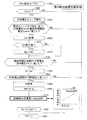
前記降圧スイープ中であって前記印加電圧が硫黄酸化物の分解開始電圧以下の第3電圧以下であり且つ前記第1電圧より高い第4電圧以上の検出用電圧範囲内となっている期間に前記電流検出部により検出される出力電流、のうちの最小値を、前記第1電流として取得する(図10のステップ1020乃至ステップ1030)ように構成されている。
In one aspect of the detection device of the present invention,
The measurement control unit
During the step-down sweep, the applied voltage is equal to or lower than a third voltage equal to or lower than the sulfur oxide decomposition start voltage and within a detection voltage range equal to or higher than a fourth voltage higher than the first voltage. The minimum value of the output current detected by the current detection unit is acquired as the first current (
印加電圧が上記検出用電圧範囲内の電圧となっている期間(即ち、硫黄の再酸化反応が活発に生じている期間)における出力電流の最小値は、硫黄酸化物の濃度を精度良く表す。この最小値が上記第1電流として用いられることによって、上記差分がより精度良く硫黄酸化物の濃度を表す値になる。従って、排気中に所定濃度以上の硫黄酸化物が含まれているか否かの判定又は排気中の硫黄酸化物の濃度の検出を精度良く行うことができる。 The minimum value of the output current in the period in which the applied voltage is within the above detection voltage range (that is, the period in which sulfur reoxidation reaction is actively occurring) accurately represents the concentration of sulfur oxide. By using this minimum value as the first current, the difference becomes a value representing the concentration of sulfur oxide more accurately. Therefore, it is possible to accurately determine whether or not the exhaust contains sulfur oxide at a predetermined concentration or more or detect the concentration of sulfur oxide in the exhaust.
本発明検出装置の一態様において、
前記測定制御部は、
前記降圧スイープ中であって前記印加電圧が硫黄酸化物の分解開始電圧以下の第3電圧以下であり且つ前記第1電圧より高い第4電圧以上の検出用電圧範囲から選ばれる電流取得電圧(Vg)になったときに前記電流検出部により検出される出力電流を、前記第1電流として取得するように構成されている。
In one aspect of the detection device of the present invention,
The measurement control unit
A current acquisition voltage (Vg) selected from a voltage range for detection that is not less than a third voltage that is not more than a decomposition start voltage of sulfur oxide and that is not less than a fourth voltage that is higher than the first voltage and that is during the step-down sweep. ), The output current detected by the current detection unit is acquired as the first current.
印加電圧が上記検出用電圧範囲から選ばれる電流取得電圧(Vg)になったときの出力電流は、硫黄酸化物の濃度を精度良く表す。この出力電流が上記第1電流(Ig)として用いられることによって、上記差分(Idiff)が精度良く硫黄酸化物の濃度を表すことができるようになる。従って、排気中に所定濃度以上の硫黄酸化物が含まれているか否かの判定又は排気中の硫黄酸化物の濃度の検出を精度良く行うことができる。 The output current when the applied voltage becomes the current acquisition voltage (Vg) selected from the above detection voltage range accurately represents the concentration of sulfur oxide. By using this output current as the first current (Ig), the difference (Idiff) can accurately represent the concentration of sulfur oxide. Therefore, it is possible to accurately determine whether or not the exhaust contains sulfur oxide at a predetermined concentration or more or detect the concentration of sulfur oxide in the exhaust.
本発明検出装置の一態様において、
前記測定制御部は、
前記特定電圧として、前記出力電流が前記酸素の限界電流となる空燃比検出用印加電圧を採用し、
前記排気中に所定濃度以上の硫黄酸化物が含まれているか否かの前記判定又は前記排気中の硫黄酸化物の濃度の検出を行う前に、前記電圧印加部を用いて、前記印加電圧を、前記空燃比検出用印加電圧、に設定し(図8のステップ850)、
前記印加電圧が前記空燃比検出用印加電圧に設定されている場合に前記電流検出部により検出される出力電流を、前記第2電流として取得する(図10のステップ1009、図15のステップ1009)ように構成されている。
In one aspect of the detection device of the present invention,
The measurement control unit
As the specific voltage, an application voltage for air-fuel ratio detection in which the output current becomes the oxygen limit current is adopted,
Before performing the determination of whether or not the exhaust gas contains sulfur oxide of a predetermined concentration or more or the detection of the concentration of sulfur oxide in the exhaust gas, the applied voltage is set using the voltage application unit. , The applied voltage for air-fuel ratio detection (
When the applied voltage is set to the air-fuel ratio detection applied voltage, the output current detected by the current detection unit is acquired as the second current (
この態様によれば、印加電圧が空燃比検出用印加電圧に設定されていて、前記出力電流が酸素の限界電流となっているとき、その出力電流が前記第2電流として取得される。酸素の限界電流に相当する電流分は前記第1電流に含まれている。従って、このようにして得られる第2電流と第1電流との差分(Idiff)は、排気中の酸素濃度の影響を受け難いパラメータとなるから、硫黄酸化物の濃度を精度良く表すパラメータとなる。その結果、この態様のガス検出装置は、排気中に所定濃度以上の硫黄酸化物が含まれるか否かの判定又は排気中の硫黄酸化物の濃度の検出をより精度良く行うことができる。 According to this aspect, when the applied voltage is set to the air-fuel ratio detection applied voltage and the output current is the limiting current of oxygen, the output current is acquired as the second current. The current corresponding to the limiting current of oxygen is included in the first current. Accordingly, the difference (Idiff) between the second current and the first current obtained in this way is a parameter that is hardly affected by the oxygen concentration in the exhaust gas, and thus is a parameter that accurately represents the concentration of sulfur oxide. . As a result, the gas detection device according to this aspect can determine whether or not sulfur oxide having a predetermined concentration or more is contained in the exhaust gas or detect the concentration of sulfur oxide in the exhaust gas with higher accuracy.
本発明検出装置の一態様において、
前記測定制御部は、
前記昇圧スイープ中に前記印加電圧が前記第2電圧になったときに前記電流検出部により検出される出力電流を、前記第2電流として取得する(図12及び図16のそれぞれに示されたステップ1214)ように構成されている。
In one aspect of the detection device of the present invention,
The measurement control unit
The output current detected by the current detector when the applied voltage becomes the second voltage during the boost sweep is acquired as the second current (steps shown in FIGS. 12 and 16 respectively). 1214).
本発明検出装置の一態様において、
前記測定制御部は、
前記降圧スイープ中に前記印加電圧が前記第1電圧になったときに前記電流検出部により検出される出力電流を、前記第2電流として取得する(図14のステップ1440及び図17のそれぞれに示されたステップ1440)ように構成されている。
In one aspect of the detection device of the present invention,
The measurement control unit
The output current detected by the current detection unit when the applied voltage becomes the first voltage during the step-down sweep is acquired as the second current (shown in
これらの場合、降圧スイープの開始時及び終了時の何れかの時点において前記第2電流(Ib)が取得され、同じ降圧スイープ中に前記第1電流(Ig)が取得され得る。これにより、前記パラメータ(Idiff)を取得するのに必要な「第1電流及び第2電流」の両方を短い期間内に取得することができる。 In these cases, the second current (Ib) can be acquired at any point in time when the step-down sweep starts and ends, and the first current (Ig) can be acquired during the same step-down sweep. Thereby, both the “first current and the second current” necessary for obtaining the parameter (Idiff) can be obtained within a short period.
従って、その期間において排気中の酸素濃度が大きく変化する可能性が低くなるので、第1電流及び第2電流のそれぞれに及ぼされる排気中の酸素濃度の影響の程度を互いに略一致させることができる。その結果、差分(Idiff)が、排気中の酸素濃度の影響を受け難く且つ排気中の硫黄酸化物の濃度により精度良く応じた値になるから、排気中に所定濃度以上の硫黄酸化物が含まれるか否かの判定又は排気中の硫黄酸化物の濃度の検出をより精度良く行うことができる。 Therefore, since the possibility that the oxygen concentration in the exhaust gas greatly changes during that period is reduced, the degree of the influence of the oxygen concentration in the exhaust gas exerted on each of the first current and the second current can be substantially matched with each other. . As a result, the difference (Idiff) is hardly affected by the oxygen concentration in the exhaust gas, and becomes a value that accurately corresponds to the sulfur oxide concentration in the exhaust gas. Or the detection of the concentration of sulfur oxide in the exhaust gas can be performed with higher accuracy.
上記説明においては、本発明の理解を助けるために、後述する実施形態に対応する発明の構成に対し、その実施形態で用いた名称及び/又は符号を括弧書きで添えている。しかしながら、本発明の各構成要素は、前記名称及び/又は符号によって規定される実施形態に限定されるものではない。本発明の他の目的、他の特徴及び付随する利点は、以下の図面を参照しつつ記述される本発明の実施形態についての説明から容易に理解されるであろう。 In the above description, in order to help understanding of the present invention, names and / or symbols used in the embodiment are attached to the configuration of the invention corresponding to the embodiment described later in parentheses. However, each component of the present invention is not limited to the embodiment defined by the names and / or symbols. Other objects, other features and attendant advantages of the present invention will be readily understood from the description of the embodiments of the present invention described with reference to the following drawings.
以下、本発明の各実施形態に係るガス検出装置について図面を参照しながら説明する。尚、実施形態の全図において、同一又は対応する部分には同一の符号を付す。 Hereinafter, gas detection devices according to embodiments of the present invention will be described with reference to the drawings. In all the drawings of the embodiment, the same or corresponding parts are denoted by the same reference numerals.
<第1実施形態>
本発明の第1実施形態に係るガス検出装置(以下、「第1検出装置」と称呼される場合がある。)について説明する。第1検出装置は、「図1に示された内燃機関10」を搭載した図示しない車両に適用される。
<First Embodiment>
A gas detection device according to a first embodiment of the present invention (hereinafter sometimes referred to as “first detection device”) will be described. The first detection device is applied to a vehicle (not shown) on which “the
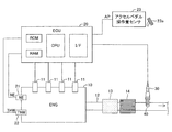
内燃機関10は周知のディーゼルエンジンである。内燃機関10は、図示しない燃焼室と、燃料噴射弁11と、を含む。燃料噴射弁11は、燃焼室内に燃料を噴射することができるようにシリンダヘッド部に配設されている。燃料噴射弁11は、後述するECU20の指示に応じて燃焼室内に燃料を直接噴射する。排気管12は、図示しない燃焼室に連通する排気ポートに接続された図示しないエキゾーストマニホールドの端部に接続されている。排気ポート、エキゾーストマニホールド及び排気管12は、燃焼室から排出された排気が流れる排気通路を構成している。排気管12には、DOC(Diesel Oxidation Catalyst:ディーゼル用酸化触媒)13及びDPF(Diesel Particulate Filter)14が配設されている。
The
DOC13は、排気浄化触媒である。具体的に述べると、DOC13は、白金及びパラジウム等の貴金属を触媒として、排気中の未燃成分(HC、CO)を酸化し、排気を浄化する。即ち、DOC13により、HCは水とCO2に酸化され、COはCO2に酸化される。
The
DPF14は、DOC13よりも下流側に配置されている。DPF14は、排気中の微粒子(パティキュレート)を捕捉するフィルタである。具体的に述べると、DPF14は、多孔質材料(例えば、セラミックの一種であるコージライトからなる隔壁)によって形成された複数の通路を備えている。DPF14は、隔壁を通過する排気に含まれる微粒子を、その隔壁の細孔表面にて捕集する。
The
第1検出装置は、ECU20を含む。ECU20は、CPU、ROM、RAM、バックアップRAM及びインターフェース(I/F)を含むマイクロコンピュータを主要構成部品として有する電子制御回路である。CPUは、メモリ(ROM)に格納されたインストラクション(ルーチン)を実行することにより、所定の機能を実現するようになっている。
The first detection device includes an
ECU20は、内燃機関10の各種アクチュエータ(燃料噴射弁11等)に接続されている。ECU20は、これらのアクチュエータに駆動(指示)信号を送出し、内燃機関10を制御するようになっている。更に、ECU20は、以下に述べる各種センサ類と接続されていて、これらのセンサ類からの信号を受け取るようになっている。
The
機関回転速度センサ21:機関回転速度センサ(以下、「NEセンサ」と称呼する。)21は、内燃機関10の回転速度(機関回転速度)NEを測定し、この機関回転速度NEを表す信号を出力するようになっている。
Engine rotational speed sensor 21: An engine rotational speed sensor (hereinafter referred to as "NE sensor") 21 measures a rotational speed (engine rotational speed) NE of the
水温センサ22:水温センサ22は、シリンダブロック部に配設されている。水温センサ22は、内燃機関10を冷却する冷却水の温度(冷却水温THW)を測定し、この冷却水温THWを表す信号を出力するようになっている。
Water temperature sensor 22: The
アクセルぺダル操作量センサ23:アクセルペダル操作量センサ23は、車両のアクセルペダル23aの操作量(アクセル開度)を検出し、アクセルペダル操作量APを表す信号を出力するようになっている。
Accelerator pedal operation amount sensor 23: The accelerator pedal
ガスセンサ30:ガスセンサ30は、1セル式の限界電流式ガスセンサであり、機関10の排気経路を構成する排気管12に配設されている。ガスセンサ30は、排気管12に介装されたDOC13及びDPF14よりも下流側に配設されている。
Gas sensor 30: The
(ガスセンサの構成)
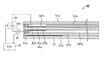
次に、ガスセンサ30の構成について、図2を参照しながら説明する。ガスセンサ30が備える素子部40は、固体電解質体41s、第1アルミナ層51a、第2アルミナ層51b、第3アルミナ層51c、第4アルミナ層51d、第5アルミナ層51e、拡散抵抗部(拡散律速層)61及びヒータ71を備える。
(Configuration of gas sensor)
Next, the configuration of the
固体電解質体41sは、ジルコニア等を含み、酸化物イオン伝導性を有する薄板体である。固体電解質体41sを形成するジルコニアは、例えば、スカンジウム(Sc)及びイットリウム(Y)等の元素を含んでいてもよい。
The
第1乃至第5アルミナ層51a乃至51eは、アルミナを含む緻密(ガス不透過性)の層(緻密な薄板体)である。
The first to
拡散抵抗部61は、多孔質の拡散律速層であり、ガス透過性の層(薄板体)である。ヒータ71は、例えば、白金(Pt)とセラミックス(例えば、アルミナ等)とを含むサーメットの薄板体であり、通電によって発熱する発熱体である。ヒータ71は、図示しないリード線によって車両に搭載された図示しない電源に接続されている。ヒータ71は、ECU20によって「その電源から供給される電力量」が制御されることにより、発熱量を変更できるようになっている。
The
素子部40の各層は、下方から、第5アルミナ層51e、第4アルミナ層51d、第3アルミナ層51c、固体電解質体41s、拡散抵抗部61及び第2アルミナ層51b、第1アルミナ層51aの順に積層されている。
Each layer of the
内部空間SP1は、第1アルミナ層51a、固体電解質体41s、拡散抵抗部61及び第2アルミナ層51bによって形成される空間であり、その中に拡散抵抗部61を介して被検ガスとしての内燃機関10の排気が導入されるようになっている。即ち、内部空間SP1は拡散抵抗部61を介して内燃機関10の排気管12の内部と連通している。従って、排気管12内の排気が内部空間SP1内に被検ガスとして導かれる。
The internal space SP1 is a space formed by the
第1大気導入路SP2は、固体電解質体41s、第3アルミナ層51c及び第4アルミナ層51dによって形成され、排気管12の外部の大気に開放されている。
The first atmosphere introduction path SP2 is formed by the
第1電極41aは、固体電解質体41sの一方の側の表面(具体的には、内部空間SP1を画定する固体電解質体41sの表面)に固着されている。第1電極41aは陰極である。第1電極41aは、白金(Pt)を主成分として含む多孔質サーメット電極である。
The
第2電極41bは、固体電解質体41sの他方の側の表面(具体的には、第1大気導入路SP2を画定する固体電解質体41sの表面)に固着されている。第2電極41bは陽極である。第2電極41bは、白金(Pt)を主成分として含む多孔質サーメット電極である。
The
第1電極41aと第2電極41bとは、固体電解質体41sを挟んで互いに対向するように配置されている。即ち、第1電極41a、第2電極41b及び固体電解質体41sは、酸素ポンピング作用による酸素排出能力を有する電気化学セル41cを構成している。電気化学セル41cは、ヒータ71により、活性化温度まで加熱される。
The
固体電解質体41s及び第1乃至第5アルミナ層51a乃至51eの各層は、例えばドクターブレード法及び押し出し成形法等により、シート状に成形されている。第1電極41a、第2電極41b及びこれらの電極に通電するための配線等は、例えばスクリーン印刷法等によって形成されている。これらのシートを上述したように積層して焼成することにより、上記のような構造を有する素子部40が一体的に製造されている。
Each of the
尚、第1電極41aを構成する材料は、上記の材料に限定されず、例えば、白金(Pt)、ロジウム(Rh)、パラジウム(Pd)等の白金族元素又はそれらの合金等を主成分として含む材料から選択することができる。但し、第1電極41aを構成する材料は、第1電極41aと第2電極41bとの間にSOx分解開始電圧以上の電圧(具体的には、約0.6V以上の電圧)を印加したときに、拡散抵抗部61を介して内部空間SP1に導かれた排気中に含まれるSOxを還元分解させることができる限り、特に限定されない。
In addition, the material which comprises the
ガスセンサ30は、更に、電源回路81及び電流計91を備える。電源回路81及び電流計91は上述したECU20に接続されている。
The
電源回路81は、第1電極41aと第2電極41bとの間に、第2電極41bの電位が第1電極41aの電位よりも高くなるように所定の電圧(以下、「印加電圧Vm」とも称呼する。)を印加できるようになっている。電源回路81は、ECU20により制御されることにより、印加電圧Vmを変更できるようになっている。
The
電流計91は、第1電極41aと第2電極41bとの間に流れる電流(従って、固体電解質体41sを流れる電流)である出力電流(電極電流)Imを計測して、その計測値をECU20に出力するようになっている。
The
<作動の概要>
次に、第1検出装置が行う作動の概要について説明する。第1検出装置は、内燃機関10から排出される排気(被検ガス)の酸素濃度を検出するように構成されている。第1検出装置は、排気中の酸素濃度に基づいて内燃機関10の燃焼室内の混合気の空燃比(A/F)を検出するように構成されている。以下、内燃機関10の燃焼室内の混合気の空燃比は、「機関の空燃比A/F」とも称呼される。更に、第1検出装置は、排気に含まれる所定濃度以上のSOxの有無を判定するように構成されている。第1検出装置は、SOxの有無の検出開始から検出終了までに数秒を必要とするため、機関の空燃比A/Fが安定している状態において所定濃度以上のSOxの有無を判定するように構成されている。
<Overview of operation>
Next, the outline | summary of the action | operation which a 1st detection apparatus performs is demonstrated. The first detection device is configured to detect the oxygen concentration of exhaust gas (test gas) exhausted from the
具体的に述べると、図3(A)に示したように、内燃機関10の始動が開始した時点である時刻t0になると、第1検出装置はヒータ71によって固体電解質体41sを加熱するように、ヒータ71に対する制御を開始する。これによって、固体電解質体41sが、酸化物イオン伝導性を発現する温度(以後、「活性化温度」と称呼される場合がある。)以上の所定の温度まで昇温される。
More specifically, as shown in FIG. 3A, at time t0, which is the time when the
時刻t1で、固体電解質体41sの温度(センサ素子温度)が活性化温度以上になって、ガスセンサ30がセンサ活性の状態になると、第1検出装置は、排ガスの酸素濃度を検出し当該酸素濃度に基づいて機関の空燃比A/Fを取得するための処理を開始する。尚、時刻t0から時刻t1の間の時点である時刻tdで、第1検出装置は、第1電極41a及び第2電極41b間に、酸素濃度の検出に適した酸素濃度(A/F)検出用の電圧(具体的に述べると0.4V)の印加を開始する。即ち、第1検出装置は、印加電圧Vmを酸素濃度検出用の電圧に設定する。固体電解質体41sの温度が活性化温度以上であるときに、この印加電圧Vmが酸素濃度検出用の電圧に設定されている場合、酸素分子が分解されて酸素ポンピング作用が発現するが、酸素以外の酸素含有成分(SOxを含む。)のガスが分解されることはない。酸素濃度検出用の電圧は酸素以外の酸素含有成分(SOxを含む)の分解開始電圧よりも低いので、酸素以外の酸素含有成分が分解されることはない。
At time t1, when the temperature of the
第1検出装置は、時刻t1から、酸素濃度を連続的に検出することにより機関の空燃比A/Fを監視する。そして、時刻t2で、SOx検出開始条件を満たすと(即ち、機関の空燃比A/Fが安定した状態になり、且つ、後述するその他の条件が満たされると)、第1検出装置は排気中のSOx濃度検出の処理を開始する。即ち、時刻t1から時刻t2の直前までの期間、第1検出装置は機関の空燃比A/Fを検出し、SOx検出を開始する時点である時刻t2にて機関の空燃比A/Fの検出を停止する。 The first detection device monitors the air-fuel ratio A / F of the engine by continuously detecting the oxygen concentration from time t1. When the SOx detection start condition is satisfied at time t2 (that is, when the air-fuel ratio A / F of the engine is in a stable state and other conditions described later are satisfied), the first detection device is exhausting. The SOx concentration detection process is started. That is, during the period from time t1 to immediately before time t2, the first detection device detects the air-fuel ratio A / F of the engine, and detects the air-fuel ratio A / F of the engine at time t2, which is the time when SOx detection starts. To stop.
尚、本明細書において、SOx濃度検出とは、排気中のSOx濃度そのものを検出(測定)すること、及び、排気中のSOx濃度を表すパラメータを取得することの両方を指す。本検出装置は、後述するように、排気中のSOx濃度を表すパラメータ(SOx濃度に応じて変化するパラメータ)を取得し、そのパラメータを用いて排気中に所定濃度以上のSOxが排気中に含まれているか否かの判定を行う。所定濃度としては、所望の検出レベルに応じた0よりも大きい濃度が選ばれる。 In this specification, the SOx concentration detection refers to both detecting (measuring) the SOx concentration itself in the exhaust gas and obtaining a parameter representing the SOx concentration in the exhaust gas. As will be described later, this detection device acquires a parameter representing the SOx concentration in the exhaust gas (a parameter that changes according to the SOx concentration), and uses that parameter to contain SOx of a predetermined concentration or higher in the exhaust gas. It is determined whether or not As the predetermined concentration, a concentration greater than 0 corresponding to a desired detection level is selected.
時刻t2から時刻t3の直前までの期間、第1検出装置は所定の印加電圧範囲(印加電圧スイープ範囲(下限電圧(第1電圧V1)及び上限電圧(第2電圧V2))で印加電圧スイープを行う。即ち、第1検出装置は、印加電圧Vmを「第1電圧V1から第2電圧V2まで徐々に増大させる昇圧スイープ」を行った後、印加電圧Vmを「第2電圧V2から第1電圧V1まで徐々に減少させる降圧スイープ」を行う。第1検出装置は、1回の昇圧スイープ及び1回の降圧スイープを1サイクルとする印加電圧スイープを、1サイクル行う。但し、第1検出装置は、印加電圧スイープを複数サイクル行っても良い。 During a period from time t2 to immediately before time t3, the first detection device performs an applied voltage sweep within a predetermined applied voltage range (applied voltage sweep range (lower voltage (first voltage V1) and upper voltage (second voltage V2)). That is, the first detection device performs the “step-up sweep that gradually increases the applied voltage Vm from the first voltage V1 to the second voltage V2”, and then changes the applied voltage Vm from “the second voltage V2 to the first voltage”. The first detection device performs one cycle of the applied voltage sweep in which one step-up sweep and one step-down sweep are one cycle, provided that the first detection device performs the step-down sweep that gradually decreases to V1. The applied voltage sweep may be performed for a plurality of cycles.
尚、第1検出装置は、酸素濃度(A/F)検出用の印加電圧が第1電圧V1より大きい場合、印加電圧Vmを、酸素濃度検出用の印加電圧から1回目の昇圧スイープを開始するようにしてもよい。代替えとして、第1検出装置は、酸素濃度検出用の印加電圧が第1電圧V1より大きい場合、印加電圧Vmを酸素濃度検出用の印加電圧から第1電圧V1に、一旦下げてから1回目の昇圧スイープを開始するようにしてもよい。 When the applied voltage for detecting the oxygen concentration (A / F) is higher than the first voltage V1, the first detecting device starts the first boost sweep of the applied voltage Vm from the applied voltage for detecting the oxygen concentration. You may do it. As an alternative, when the applied voltage for oxygen concentration detection is higher than the first voltage V1, the first detection device lowers the applied voltage Vm from the applied voltage for oxygen concentration detection to the first voltage V1, and then first time You may make it start a pressure | voltage rise sweep.
より具体的に述べると、第1検出装置は、図3(B)に示したように、正弦波の波形(一周期分)を有する電圧を第1電極41a及び第2電極41bの間に印加することにより、印加電圧スイープを行う。尚、この場合の電圧波形は、図3(B)に示した正弦波に限定されるものではなく、種々の波形を採用し得る。例えば、この場合の電圧波形は、図3(C)のグラフに示したような非正弦波(キャパシタの充放電時の電圧波形のような波形)であってもよい。
More specifically, as shown in FIG. 3B, the first detection device applies a voltage having a sinusoidal waveform (for one cycle) between the
時刻t3で、SOx検出が終了すると、第1検出装置は、機関の空燃比A/Fを検出するための処理を再開する。即ち、第1検出装置は、時刻t3で、印加電圧Vmを酸素濃度検出用の電圧(0.4V)に設定する。 When the SOx detection ends at time t3, the first detection device resumes the process for detecting the air-fuel ratio A / F of the engine. That is, the first detection device sets the applied voltage Vm to the oxygen concentration detection voltage (0.4 V) at time t3.
(A/F検出)
次に、上述した機関の空燃比A/Fを検出する際の作動について説明する。第1検出装置は、ガスセンサ30がセンサ活性の状態になると、機関の空燃比A/Fを取得するために、第1電極41aが低電位となり且つ第2電極41bが高電位となるように、印加電圧Vmを酸素濃度検出用の電圧(例えば、0.4V)に設定する。即ち、第1電極41aは陰極として機能し、第2電極41bは陽極として機能する。酸素濃度検出用の電圧は、第1電極41aにおいて酸素(O2)の分解が始まる電圧(分解開始電圧)以上であって且つ酸素以外の酸素含有成分の分解開始電圧未満の電圧に設定される。これにより、排気中に含まれる酸素が第1電極41aにおいて還元分解されて酸化物イオン(O2−)となる。
(A / F detection)
Next, the operation for detecting the above-described engine air-fuel ratio A / F will be described. When the
この酸化物イオンは上記固体電解質体41sを介して第2電極41bへと伝導されて酸素(O2)となり、大気導入路SP2を通じて大気中へと排出される。前述したように、このような陰極(第1電極41a)から陽極(第2電極41b)への固体電解質体41sを介する酸化物イオンの伝導による酸素の移動は「酸素ポンピング作用」と称される。
The oxide ions are conducted to the
この酸素ポンピング作用に伴う酸化物イオンの伝導により、第1電極41aと第2電極41bとの間に電流が流れる。第1電極41aと第2電極41bとの間に流れる電流は「出力電流Im(或いは電極電流Im)」と称呼される。出力電流Imは、一般には、印加電圧Vmが上昇するほど大きくなる傾向を有する。しかしながら、第1電極41aに到達する排気の流量が拡散抵抗部61によって制限されるので、やがて酸素ポンピング作用に伴う酸素の消費速度が第1電極41aへの酸素の供給速度を超えるようになる。即ち、第1電極41a(陰極)における酸素の還元分解反応が拡散律速状態となる。
A current flows between the
第1電極41aにおける酸素の還元分解反応が拡散律速状態となると、印加電圧Vmを上昇させても出力電流Imが増大せず、略一定となる。このような特性は「限界電流特性」と称呼される。限界電流特性が発現する(観測される)印加電圧の範囲は「限界電流域」と称呼される。更に、限界電流域における出力電流Imは「限界電流」と称呼される。酸素に対する限界電流の大きさ(限界電流値)は第1電極41a(陰極)への酸素の供給速度に対応する。上述したように、第1電極41aに到達する排気の流量は拡散抵抗部61によって一定に維持されているので、第1電極41aへの酸素の供給速度は排気に含まれる酸素の濃度に対応する。
When the oxygen reductive decomposition reaction in the
従って、ガスセンサ30において、印加電圧Vmを「酸素の限界電流域内の所定の電圧(酸素濃度検出用の電圧であり、具体的に述べると0.4V)」に印加電圧Vmを設定したときの出力電流(限界電流)Imは排気に含まれる酸素の濃度に対応する。このように酸素の限界電流特性を利用して、第1検出装置は被検ガスとしての排気中に含まれる酸素の濃度を検出する。一方、機関の空燃比A/Fと排気中の酸素の濃度とは、一対一の関係がある。従って、第1検出装置は、この関係を予めROMに記憶させておき、その関係と検出した酸素濃度とに基づいて機関の空燃比A/Fを取得する。尚、第1検出装置は、酸素の限界電流と機関の空燃比A/Fとの関係を予めROMに記憶させておき、その関係と検出した酸素の限界電流とに基づいて機関の空燃比A/Fを取得してもよい。
Therefore, in the
(SOx濃度検出)
[検出原理]
次に、排気中のSOx濃度の検出の仕方について説明する。上述した酸素ポンピング作用は、分子中に酸素原子を含む「SOx(硫黄酸化物)及びH2O(水)等」の酸素含有成分に対しても発生する。即ち、第1電極41a及び第2電極41b間に、これらの化合物のそれぞれの分解開始電圧以上の電圧を印加すると、これらの化合物のそれぞれが還元分解されることによって、酸化物イオンが生じる。この酸化物イオンは、「酸素ポンピング作用」によって、第1電極41aから第2電極41bへと伝導される。これにより、第1電極41a及び第2電極41b間に出力電流Imが流れる。
(SOx concentration detection)
[Detection principle]
Next, how to detect the SOx concentration in the exhaust will be described. The oxygen pumping action described above also occurs for oxygen-containing components such as “SOx (sulfur oxide) and H 2 O (water)” containing oxygen atoms in the molecule. That is, when a voltage higher than the decomposition start voltage of each of these compounds is applied between the
しかしながら、排気中に含まれるSOxの濃度は極めて低く、SOxの分解に起因する電流も極めて小さい。更に、SOx以外の酸素含有成分(例えば、水及び二酸化炭素等)が分解されることに起因する電流も第1電極41a及び第2電極41b間に流れる。そのため、SOxに起因する出力電流のみを精度よく検出することは困難である。
However, the concentration of SOx contained in the exhaust gas is extremely low, and the current resulting from the decomposition of SOx is also extremely small. Furthermore, a current caused by the decomposition of oxygen-containing components other than SOx (for example, water and carbon dioxide) also flows between the
そこで、本願の発明者は、鋭意検討した結果、SOx濃度を検出する際、昇圧スイープ及び「所定の掃引速度での降圧スイープ」を1サイクルとする印加電圧スイープを実行することによって、SOx濃度を精度良く検出できるとの知見を得た。 Therefore, as a result of intensive studies, the inventor of the present application has determined the SOx concentration by detecting the SOx concentration by executing an applied voltage sweep in which one step is a step-up sweep and a “step-down sweep at a predetermined sweep speed”. The knowledge that it can detect with high precision was acquired.
昇圧スイープは、印加電圧Vmを、第1電圧V1から第2電圧V2に徐々に上昇させる処理である。降圧スイープは、印加電圧Vmを、第2電圧V2から第1電圧V1に徐々に下降させる処理である。尚、第1電圧V1及び第2電圧V2は、第1電極41aの電位を基準とした第2電極41bの電位であり、正の電圧値である。
The step-up sweep is a process of gradually increasing the applied voltage Vm from the first voltage V1 to the second voltage V2. The step-down sweep is a process of gradually lowering the applied voltage Vm from the second voltage V2 to the first voltage V1. The first voltage V1 and the second voltage V2 are potentials of the
第1電圧V1は、SOxの分解開始電圧(約0.6V)よりも低く、且つ、酸素の限界電流域内の印加電圧Vmの最小値よりも高い電圧範囲(以下、「第1電圧範囲」とも称呼される。)内の電圧に設定される。酸素の限界電流域内の印加電圧Vmの最小値は、機関の空燃比A/Fに依存するから、第1電圧範囲の下限値もまた機関の空燃比A/Fに応じて変更されることが望ましい。具体的には、第1電圧範囲の下限値は例えば0.2V乃至0.45Vの範囲内の電圧であり、第1電圧範囲の上限電圧は0.6Vである。即ち、第1電圧は0.2V以上であり且つ0.6V未満の範囲から選ばれた電圧である。 The first voltage V1 is lower than the SOx decomposition start voltage (about 0.6V) and higher than the minimum value of the applied voltage Vm in the oxygen limit current region (hereinafter referred to as "first voltage range"). Is set to the voltage within. Since the minimum value of the applied voltage Vm within the oxygen limit current region depends on the air / fuel ratio A / F of the engine, the lower limit value of the first voltage range may also be changed according to the air / fuel ratio A / F of the engine. desirable. Specifically, the lower limit value of the first voltage range is, for example, a voltage in the range of 0.2V to 0.45V, and the upper limit voltage of the first voltage range is 0.6V. That is, the first voltage is a voltage selected from a range of 0.2V or more and less than 0.6V.
第2電圧V2は、SOxの分解開始電圧(約0.6V)よりも高く、且つ、固体電解質体41sが破壊されない電圧の上限値(2.0V)よりも低い電圧範囲(以下、「第2電圧範囲」とも称呼される。)内の電圧に設定される。即ち、第2電圧V2は、0.6Vよりも高く且つ2.0V以下の範囲から選ばれた電圧である。
The second voltage V2 is higher than the SOx decomposition start voltage (about 0.6V) and lower than the upper limit value (2.0V) of the voltage at which the
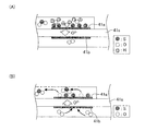
昇圧スイープを行っている期間において、第1電極41a及び第2電極41bの間に印加される印加電圧Vmが、SOxの分解開始電圧以上になると、図4(A)に示したように、第1電極41a(陰極)において排気に含まれるSOxがSとO2−とに還元分解される。その結果、SOxの還元分解生成物(S(硫黄))が、第1電極41a(陰極)に吸着する。
When the applied voltage Vm applied between the
降圧スイープを行っている期間において、印加電圧Vmが、SOxの分解開始電圧未満になると、図4(B)に示したように、第1電極41a(陰極)に吸着していたSとO2−とが反応してSOxを生成する反応(以下、「S(硫黄)の再酸化反応」と称呼する場合がある。)が生じる。このとき、「Sの再酸化反応」に起因して、出力電流Imが後述するように変化する。尚、この「Sの再酸化反応」に伴う出力電流Imの変化を「再酸化電流変化」と称呼する。
When the applied voltage Vm becomes less than the SOx decomposition start voltage during the step-down sweep, as shown in FIG. 4B, S and O 2 adsorbed on the
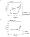
ところで、発明者の検討によれば、降圧スイープの掃引速度(所定の経過時間当たりの電圧降下量)によっては、SOx濃度検出に有意な再酸化電流変化が現れなくなる場合があることが判明した。この点について、図5(A)及び図5(B)を参照しながら説明する。 By the way, according to the inventors' investigation, it has been found that depending on the sweep speed of the step-down sweep (voltage drop amount per predetermined elapsed time), a significant reoxidation current change may not appear in the SOx concentration detection. This point will be described with reference to FIGS. 5 (A) and 5 (B).
図5(A)は、掃引周期(即ち、昇圧スイープに要する時間と降圧スイープに要する時間との和、印加電圧スイープの周期)を1秒に設定して印加電圧スイープを実行したときの印加電圧Vmと出力電流Imとの関係を示した模式的なグラフである。図5(B)は、図5(A)に示した例より遅い掃引速度(掃引周期20秒)にて、印加電圧スイープを実行したときの印加電圧Vmと出力電流Imとの関係を示した模式的なグラフである。 FIG. 5A shows the applied voltage when the applied voltage sweep is executed with the sweep period (that is, the sum of the time required for the step-up sweep and the time required for the step-down sweep, the period of the applied voltage sweep) set to 1 second. 3 is a schematic graph showing the relationship between Vm and output current Im. FIG. 5B shows the relationship between the applied voltage Vm and the output current Im when the applied voltage sweep is executed at a slower sweep speed (a sweep cycle of 20 seconds) than the example shown in FIG. It is a typical graph.
両者を比較すると、図5(B)の例より、印加電圧スイープの掃引速度がより速い図5(A)の例の方が、SOxの分解開始電圧(0.6V)よりも小さい電圧範囲にて、線L1で示した「被検ガスのSOx濃度が0ppmのときの出力電流Im」と、線L2で示した「被検ガスのSOx濃度が130ppmのときの出力電流Im」との差(電流値の差)が明確に現れている。即ち、図5(A)の例の方では、SOx濃度検出に有意な電流変化(再酸化電流変化)が現れている。このような現象が生じるメカニズムは、次のようなことであると考えられる。 Comparing the two, the example of FIG. 5A in which the sweep speed of the applied voltage sweep is faster than the example of FIG. 5B has a voltage range smaller than the SOx decomposition start voltage (0.6 V). The difference between the “output current Im when the SOx concentration of the test gas is 0 ppm” shown by the line L1 and the “output current Im when the SOx concentration of the test gas is 130 ppm” shown by the line L2 ( The difference in current value is clearly visible. That is, in the example of FIG. 5A, a significant current change (reoxidation current change) appears in the SOx concentration detection. The mechanism by which such a phenomenon occurs is considered as follows.
即ち、掃引速度を所定速度より遅くした場合、降圧スイープを行っているときに、Sの再酸化反応が連続的且つ徐々に進行するため、有意な再酸化電流変化は現れない。一方、掃引速度を所定の掃引速度より速くした場合、降圧スイープを行っているときに、Sの再酸化反応がそれ程進行しないまま印加電圧Vmが低下し、印加電圧が「Sの再酸化反応が活発になるある電圧範囲」の電圧になると、Sの再酸化反応が急激に進行すると考えられる。これにより、SOx濃度検出に有意な電流変化が現れる。 That is, when the sweep speed is made lower than the predetermined speed, since the reoxidation reaction of S proceeds continuously and gradually during the step-down sweep, no significant reoxidation current change appears. On the other hand, when the sweep speed is higher than the predetermined sweep speed, the applied voltage Vm decreases while the reoxidation reaction of S does not proceed so much during the step-down sweep, and the applied voltage becomes “the reoxidation reaction of S It is considered that the reoxidation reaction of S proceeds rapidly at a voltage in a certain voltage range that becomes active. Thereby, a significant current change appears in the SOx concentration detection.
このように、降圧スイープを行った時の掃引速度によって、SOx濃度検出に有意な電流変化が現れる場合と現れなくなる場合とが生じる。従って、降圧スイープを行うとき、掃引速度を、再酸化電流変化を示す有意な電流変化が現れるような所定速度にする必要がある。 Thus, depending on the sweep speed when the step-down sweep is performed, there are cases where a significant current change appears and does not appear in SOx concentration detection. Therefore, when performing the step-down sweep, it is necessary to set the sweep speed to a predetermined speed at which a significant current change indicating a reoxidation current change appears.
第1検出装置において、この所定速度は、予め実験を行うことによって再酸化電流変化を示す有意な電流変化が現れる適切な速度に設定される。 In the first detection device, the predetermined speed is set to an appropriate speed at which a significant current change indicating a reoxidation current change appears by performing an experiment in advance.
実験によれば、例えば、図3(B)に示した正弦波形の電圧を第1電極41a及び第2電極41b間に印加する場合、所定範囲の周波数F(典型的には、0.1Hz以上5Hz以下の範囲)となるような掃引速度に設定することが好ましいことが判明した。この所定範囲の周波数Fの下限値は、これ未満になるとSOx濃度検出に有意な信号差(再酸化電流変化)が得られなくなる観点から定められる。この所定範囲の周波数Fの上限値は、これより多くなると、SOx濃度以外の他の電流変化要因(具体的に述べると固体電解質体41sの容量等)の寄与が大きくなってしまう観点から定められる。
According to the experiment, for example, when the sinusoidal voltage shown in FIG. 3B is applied between the
一方、実験によれば、図3(C)に示したような、キャパシタの充放電に伴う非正弦波形の電圧を第1電極41a及び第2電極41b間に印加する場合、電圧切り替え波形の応答時間T1が所定範囲(典型的には、0.1秒以上5秒以下の範囲)となるような掃引速度に設定することが好ましいことが判明した。尚、応答時間T1は、印加電圧Vmが所定範囲の下限電圧から上限電圧又はその逆に変化するのに要する時間である。応答時間T1の所定範囲の下限電圧及び上限電圧は、上述した正弦波形の電圧を印加電圧として用いる場合の周波数F(上記所定の周波数)を決定する場合と同様の観点から適切な値に定められる。
On the other hand, according to an experiment, when a voltage having a non-sinusoidal waveform due to charging / discharging of the capacitor as shown in FIG. 3C is applied between the
尚、上記の周波数F及び応答時間T1の所定範囲を、降圧スイープに要する時間(即ち、第2電圧V2から第1電圧V1に達するまでの時間)に換算すると、0.1秒以上5秒以下の範囲となる。従って、当該時間は、0.1秒以上5秒以下の範囲であることが好ましい。 When the predetermined ranges of the frequency F and the response time T1 are converted into the time required for the step-down sweep (that is, the time from the second voltage V2 to the first voltage V1), the range is 0.1 second to 5 seconds. It becomes the range. Therefore, the time is preferably in the range of 0.1 seconds to 5 seconds.
更に、再酸化電流変化は、主として被検ガスである排気中のSOx濃度に依存することが判明した。換言すると、再酸化電流変化は、排気中の「硫黄酸化物(SOx)以外の酸素含有成分のガス(例えば、水)」の影響を受ける可能性が低い。即ち、昇圧スイープを行った場合に「硫黄酸化物以外の他の成分(酸素含有成分)の分解物(例えば、水の分解物である水素等)は第1電極41aに吸着しないため、降圧スイープを行っている期間において、そのような「硫黄酸化物以外の酸素含有成分」の分解物が当該第1電極41aにおいて再酸化反応して酸素含有成分へ戻る現象は実質的に生じない。
Furthermore, it has been found that the reoxidation current change mainly depends on the SOx concentration in the exhaust gas, which is the test gas. In other words, the reoxidation current change is less likely to be affected by “gas of oxygen-containing components other than sulfur oxide (SOx) (for example, water)” in the exhaust gas. That is, when a pressure-up sweep is performed, a decomposition product of other components (oxygen-containing components) other than sulfur oxide (for example, hydrogen which is a decomposition product of water) does not adsorb to the
このため、降圧スイープを行っているときに第1電極41aに吸着していた硫黄が当該第1電極41aにおいて再酸化反応して硫黄酸化物へと戻ることにより生じる「出力電流の変化」は、硫黄酸化物以外の酸素含有成分の影響を受けにくい。即ち、硫黄酸化物以外の酸素含有成分の影響を受けにくい「出力電流の変化」が生じる。
For this reason, the "change in output current" that occurs when sulfur adsorbed on the
更に、「出力電流の変化(再酸化電流変化)」は、排気(被検ガス)中のSOx濃度が大きくなるほど出力電流Imが小さくなっていくような特性を有するように現れることが判明した。即ち、硫黄の再酸化反応が生じた場合、図4(B)に示したように、第1電極41aにおいて酸化物イオンが消費されるため、第1電極41aから第2電極41bへ移動する酸化物イオン(例えば、酸素分子の分解により生じる酸化物イオン)の移動量が減少する。これにより、出力電流Imは減少する。排気中のSOx濃度が大きくなるほど、特に昇圧スイープ中に第1電極41aに吸着する硫黄の量が多くなり、よって、特に降圧スイープ中に第1電極41aにおいて硫黄と反応して消費される酸化物イオンの量も多くなる。その結果、第1電極41aから第2電極41bへ移動する酸化物イオンの量も減少する。従って、排気中のSOx濃度が大きくなるほど、出力電流Imは減少する。
Furthermore, it has been found that the “change in output current (change in reoxidation current)” appears to have such characteristics that the output current Im decreases as the SOx concentration in the exhaust gas (test gas) increases. That is, when a sulfur reoxidation reaction occurs, oxide ions are consumed in the
以上により、上述した「再酸化電流変化を利用することにより、排気中のSOx以外の酸素含有成分のガス(例えば、水)の影響を受けることなく、精度よく排気中のSOx濃度を検出することができる。」ことが理解される。よって、第1検出装置は、この再酸化電流変化を利用してSOx濃度検出(実際には、所定濃度以上のSOxの有無の判定)を行う。 As described above, by utilizing the change in the reoxidation current described above, it is possible to accurately detect the SOx concentration in the exhaust gas without being affected by the oxygen-containing component gas (for example, water) other than the SOx in the exhaust gas. Is understood. " Therefore, the first detection device performs SOx concentration detection (actually, the determination of the presence or absence of SOx above a predetermined concentration) using this change in reoxidation current.
[再酸化電流変化を検出するためのパラメータ]
第1検出装置は、「再酸化電流変化」を適切に(精度良く)表すパラメータを取得し、このパラメータに基づいて、SOx濃度検出を行う。より具体的に述べると、第1検出装置は、降圧スイープ中において印加電圧Vmが「電流取得開始電圧(第3電圧)Vsem以下であり、且つ、第1電圧V1より高い第4電圧V4以上の範囲(検出用電圧範囲)内」になっている期間の出力電流Imのうちの最小値を、当該期間の出力電流Imに相関を有する値(即ち、第1電流Ig)として取得する。
[Parameters for detecting changes in reoxidation current]
The first detection device acquires a parameter that appropriately (accurately) represents a “reoxidation current change”, and performs SOx concentration detection based on this parameter. More specifically, in the first detection device, the applied voltage Vm is “current acquisition start voltage (third voltage) Vsem or lower and higher than the fourth voltage V4 higher than the first voltage V1 during the step-down sweep. The minimum value of the output current Im in the period “within range (voltage range for detection)” is acquired as a value correlated with the output current Im in the period (that is, the first current Ig).
電流取得開始電圧Vsemは、降圧スイープの下限電圧(第1電圧V1)より大きく、且つ、SOxの分解開始電圧(0.6V)以下の範囲内から選ばれる。本例において、電流取得開始電圧Vsemは、0.6Vに設定されている。尚、電流取得開始電圧Vsemは、印加電圧スイープの印加電圧範囲及び印加電圧スイープの周期(換言すると、印加電圧スイープの掃引速度)の少なくとも1つに応じて異なるようにしてもよい。電流取得開始電圧Vsemは、「印加電圧スイープの電圧範囲の下限電圧(第1電圧V1)よりも大きく、且つ、SOx分解開始電圧(0.6V)未満」であってもよく、好ましくは第1電圧V1よりも大きく且つ0.45V以下であってもよい。 The current acquisition start voltage Vsem is selected from a range that is greater than the lower limit voltage (first voltage V1) of the step-down sweep and equal to or less than the SOx decomposition start voltage (0.6V). In this example, the current acquisition start voltage Vsem is set to 0.6V. The current acquisition start voltage Vsem may be different according to at least one of the applied voltage range of the applied voltage sweep and the cycle of the applied voltage sweep (in other words, the applied voltage sweep sweep speed). The current acquisition start voltage Vsem may be “greater than the lower limit voltage (first voltage V1) of the voltage range of the applied voltage sweep and less than the SOx decomposition start voltage (0.6V)”, preferably the first It may be larger than the voltage V1 and not more than 0.45V.
更に、第1検出装置は、「印加電圧Vmが機関のA/Fを検出するための電圧であるときの出力電流Im」を、第2電流Ibとして取得する。更に、第1検出装置は、第2電流Ibから第1電流Igを引いた差分Idiff(=Ib−Ig)を、「再酸化電流変化を表すパラメータ」として取得する。そして、第1検出装置は、このパラメータ(差分Idiff)に基づいてSOx濃度検出(実際には、所定濃度以上のSOxの有無の判定)を行う。 Further, the first detection device acquires “the output current Im when the applied voltage Vm is a voltage for detecting the A / F of the engine” as the second current Ib. Further, the first detection device acquires a difference Idiff (= Ib−Ig) obtained by subtracting the first current Ig from the second current Ib as “a parameter indicating a reoxidation current change”. Then, the first detection device performs SOx concentration detection (in practice, determination of the presence or absence of SOx above a predetermined concentration) based on this parameter (difference Idiff).
第1検出装置は、印加電圧スイープを1サイクルだけ行って差分Idiffを取得するが、次のように構成されてもよい。即ち、第1検出装置は、印加電圧スイープを複数サイクル行い、且つ、各サイクルで差分Idiffを取得するようにし、取得した複数の「差分Idiff」の平均値を、「再酸化電流変化を表すパラメータ」として用いるように構成されてもよい。 The first detection device performs the applied voltage sweep for one cycle to obtain the difference Idiff, but may be configured as follows. That is, the first detection device performs the applied voltage sweep for a plurality of cycles and obtains the difference Idiff in each cycle, and obtains the average value of the obtained “difference Idiff” as the “parameter indicating the change in reoxidation current”. May be used.
[SOx濃度検出方法]
第1検出装置は、以上説明したSOx濃度の検出原理を用いて、SOx濃度検出(実際には、所定濃度以上のSOxの有無の判定)を次のように行うようになっている。
・第1検出装置は、所定の掃引速度にて印加電圧スイープを実行する。この場合、特に、大切な点は、降圧スイープ速度である。
このとき、第1検出装置は、直前に取得しておいた「排気中の酸素濃度」を用いて検出される機関の空燃比A/Fに基づいて印加電圧スイープの電圧範囲(即ち、第1電圧V1及び第2電圧V2)を決定する。
・第1検出装置は、A/F検出時の印加電圧(0.4V)の出力電流Imを第2電流Ibとして取得する。
・第1検出装置は、降圧スイープ中であって印加電圧Vmが検出用電圧範囲(第1電圧V1より高く電流取得開始電圧Vsem以下の範囲)であるときの出力電流Imの最小値を、第1電流Igとして取得する。
・第1検出装置は、第2電流Ibから第1電流Igを引いた差分Idiff(=Ib−Ig)を算出する。この差分Idiffが、排気中のSOx濃度を表すパラメータである。
・第1検出装置は、差分Idiffに基づいて、所定濃度以上のSOx濃度が排気中に含まれているか否かを判定する。
[SOx concentration detection method]
The first detection apparatus performs SOx concentration detection (in practice, determination of the presence or absence of SOx above a predetermined concentration) using the SOx concentration detection principle described above as follows.
The first detection device performs an applied voltage sweep at a predetermined sweep speed. In this case, the important point is the step-down sweep speed.
At this time, the first detection device detects the voltage range of the applied voltage sweep (that is, the first voltage range) based on the air / fuel ratio A / F of the engine detected using the “oxygen concentration in the exhaust gas” acquired immediately before. The voltage V1 and the second voltage V2) are determined.
-A 1st detection apparatus acquires the output current Im of the applied voltage (0.4V) at the time of A / F detection as the 2nd electric current Ib.
The first detection device determines the minimum value of the output current Im when the applied voltage Vm is in the detection voltage range (a range higher than the first voltage V1 and lower than the current acquisition start voltage Vsem) during the step-down sweep. Acquired as 1 current Ig.
The first detection device calculates a difference Idiff (= Ib−Ig) obtained by subtracting the first current Ig from the second current Ib. This difference Idiff is a parameter representing the SOx concentration in the exhaust gas.
-A 1st detection apparatus determines whether SOx density | concentration more than a predetermined density | concentration is contained in exhaust_gas | exhaustion based on difference Idiff.
具体的に述べると、第1検出装置は、SOx濃度検出の印加電圧スイープを実行する場合、図3(B)に示した正弦波の電圧波形を有する電圧の一周期分を第1電極41a及び第2電極41b間に印加する。このとき、第1検出装置は、既述のSOx濃度検出に有意な電流変化が生じるような上述した「所定の掃引速度」にて、印加電圧スイープ(昇圧スイープ及び降圧スイープ)を実行する。
Specifically, when executing the applied voltage sweep for detecting the SOx concentration, the first detection device uses one cycle of the voltage having the voltage waveform of the sine wave shown in FIG. Applied between the
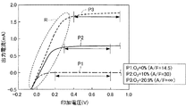
このとき、第1検出装置は、機関の空燃比A/Fに基づいて印加電圧スイープの電圧範囲(印加電圧スイープの下限電圧(第1電圧V1)及び上限電圧(第2電圧V2))を決定する。具体的には、図6に示したように、印加電圧スイープの下限電圧は、点線Rで囲まれた内部抵抗依存域の出力電流Imを検出することを避けるように定められる。この内部抵抗依存域とは、印加電圧Vmの増大に伴って出力電流Imが増大する領域(酸素の限界電流域に到達する直前の領域)である。内部抵抗依存域の印加電圧Vmの上限値(即ち、酸素の限界電流域内の印加電圧の最小値)は、機関の空燃比A/Fがリーンになる(排気中の酸素濃度が大きくなる)に従い高くなる。印加電圧スイープの上限電圧は、一定であってもよいが、印加電圧スイープの下限電圧(第1電圧V1)は、機関の空燃比A/Fがリーンになるほど、高くなるように定められる。 At this time, the first detection device determines the voltage range of the applied voltage sweep (the lower limit voltage (first voltage V1) and the upper limit voltage (second voltage V2) of the applied voltage sweep) based on the air-fuel ratio A / F of the engine. To do. Specifically, as shown in FIG. 6, the lower limit voltage of the applied voltage sweep is determined so as to avoid detecting the output current Im in the internal resistance dependent region surrounded by the dotted line R. This internal resistance dependent region is a region in which the output current Im increases as the applied voltage Vm increases (region immediately before reaching the oxygen limit current region). The upper limit value of the applied voltage Vm in the internal resistance dependent region (that is, the minimum value of the applied voltage in the limiting current region of oxygen) is as the engine air-fuel ratio A / F becomes leaner (the oxygen concentration in the exhaust gas becomes larger). Get higher. The upper limit voltage of the applied voltage sweep may be constant, but the lower limit voltage (first voltage V1) of the applied voltage sweep is determined to be higher as the air-fuel ratio A / F of the engine becomes leaner.
具体的に述べると、機関の空燃比A/Fがリーンになるほど、内部抵抗依存域Rの印加電圧Vmの上限値が高くなる。よって、第1検出装置は、印加電圧スイープの電圧範囲が、この内部抵抗依存域Rに入らないように、機関の空燃比A/Fがリーンになるほど印加電圧スイープの下限電圧(第1電圧V1)を高くする。 Specifically, as the air-fuel ratio A / F of the engine becomes leaner, the upper limit value of the applied voltage Vm in the internal resistance dependent region R increases. Therefore, the first detection device detects the lower limit voltage of the applied voltage sweep (the first voltage V1 as the engine air-fuel ratio A / F becomes leaner so that the voltage range of the applied voltage sweep does not enter the internal resistance dependent region R. ).
発明者の実験によれば、A/F=14.5(ストイキ)の場合、第1電圧V1は0.2V以上から選ばれた値であることが好ましく、第1検出装置は第1電圧V1を0.2Vに設定している。A/F=30の場合、第1電圧V1は0.3V以上から選ばれた値であることが好ましく、第1検出装置は第1電圧V1を0.3Vに設定している。A/F=無限大(O2濃度=20.9%)の場合、第1電圧V1は0.4V以上から選ばれた値であることが好ましく、第1検出装置は第1電圧V1を0.4Vに設定している。 According to the inventor's experiment, when A / F = 14.5 (stoichiometric), the first voltage V1 is preferably a value selected from 0.2V or more, and the first detection device is the first voltage V1. Is set to 0.2V. When A / F = 30, the first voltage V1 is preferably a value selected from 0.3V or higher, and the first detection device sets the first voltage V1 to 0.3V. When A / F = infinity (O 2 concentration = 20.9%), the first voltage V1 is preferably a value selected from 0.4 V or more, and the first detection device sets the first voltage V1 to 0. .4V is set.
既述した通り、昇圧スイープ及び降圧スイープを行った場合、排気中にSOxが含まれていると、昇圧スイープを行っている期間において、SOxが分解して生じたS(硫黄)が、第1電極41aに吸着する。降圧スイープを行っている期間において、第1電極41aに吸着したSが再酸化する。
As described above, when the boosting sweep and the bucking sweep are performed, if SOx is contained in the exhaust gas, S (sulfur) generated by decomposition of SOx during the period of performing the boosting sweep is the first. Adsorb to the
第1検出装置は、再酸化電流変化を前述したパラメータ(差分Idiff)を用いて検出することによって、SOx濃度検出(実際には、所定濃度以上のSOxの有無の判定)を行う。 The first detection device detects SOx concentration (actually, the determination of the presence or absence of SOx above a predetermined concentration) by detecting the reoxidation current change using the above-described parameter (difference Idiff).
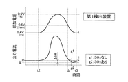
即ち、図7に示したように、第1検出装置は、印加電圧スイープを開始する時点(時刻t2)の前において印加電圧VmをA/F検出時の印加電圧(0.4V)に設定し、そのときの出力電流Imを、第2電流Ibとして取得する。更に、第1検出装置は、降圧スイープ中であって印加電圧Vmが「電流取得開始電圧Vsem(0.6V)以下であり且つ第1電圧V1よりも高い第4電圧V4以上の範囲(即ち、検出用電圧範囲)」である期間(時刻tbから時刻t3までの期間)の出力電流Im(線g2により示した出力電流Im)の最小値を、第1電流Igとして取得する。更に、第1検出装置は、第2電流Ibから第1電流Igを引いた差分Idiff(=Ib−Ig)を算出する。更に、第1検出装置は、差分Idiffに基づいて、SOx濃度検出(実際には、所定濃度以上のSOxの有無の判定)を行う。 That is, as shown in FIG. 7, the first detection device sets the applied voltage Vm to the applied voltage (0.4 V) at the time of A / F detection before the time (time t2) when the applied voltage sweep starts. The output current Im at that time is acquired as the second current Ib. Further, the first detection device is in a step-down sweep, and the applied voltage Vm is “a range of the fourth voltage V4 or higher that is equal to or lower than the current acquisition start voltage Vsem (0.6 V) and higher than the first voltage V1 (ie, The minimum value of the output current Im (the output current Im indicated by the line g2) in the period (the period from the time tb to the time t3) that is “the detection voltage range)” is acquired as the first current Ig. Further, the first detection device calculates a difference Idiff (= Ib−Ig) obtained by subtracting the first current Ig from the second current Ib. Furthermore, the first detection device performs SOx concentration detection (actually, determination of the presence or absence of SOx above a predetermined concentration) based on the difference Idiff.
線g2に示したように、排気中にSOxが含まれていれば、降圧スイープ中に印加電圧Vmが検出用電圧範囲内の電圧になっている期間(時刻tbから時刻t3の期間)の出力電流Im(第2電流Ib)は、次のようになっている。即ち、線g2に示した排気にSOxが含まれている場合の出力電流Imは、線g1に示した排気中にSOxが含まれていない場合に比べて小さくなるような「再酸化電流変化の程度」が現れるようになっている。従って、上記期間の出力電流Imの最小値(第1電流Ig)は、排気中にSOxが含まれていない場合の出力電流Imの最小値(電流Ir)より小さくなる特性を有する。更に、この第1電流Igは、SOx濃度が大きくなるほど小さくなるような特性を有する。 As shown by the line g2, if SOx is included in the exhaust gas, the output during the period during which the applied voltage Vm is within the detection voltage range during the step-down sweep (period from time tb to time t3) The current Im (second current Ib) is as follows. That is, the output current Im when the exhaust gas indicated by the line g2 contains SOx is smaller than that when the exhaust gas indicated by the line g1 does not contain SOx. "Degree" appears. Therefore, the minimum value (first current Ig) of the output current Im in the period has a characteristic that becomes smaller than the minimum value (current Ir) of the output current Im when the exhaust gas does not contain SOx. Further, the first current Ig has such characteristics that it decreases as the SOx concentration increases.
一方、降圧スイープ中に印加電圧Vmが検出用電圧範囲内の電圧になっている期間(時刻tbから時刻t3の期間)の出力電流Imは、排気中の酸素濃度の影響を受けて変化する。即ち、この出力電流Imは、排気中の酸素濃度が高いほど(機関の空燃比A/Fがリーンであるほど)大きくなる。従って、第1電流Igも、排気中の酸素濃度が高いほど大きくなる。 On the other hand, the output current Im during the period (the period from the time tb to the time t3) during which the applied voltage Vm is within the detection voltage range during the step-down sweep changes due to the influence of the oxygen concentration in the exhaust gas. That is, the output current Im increases as the oxygen concentration in the exhaust gas increases (as the air-fuel ratio A / F of the engine becomes leaner). Therefore, the first current Ig also increases as the oxygen concentration in the exhaust gas increases.
他方、印加電圧スイープ中ではなく印加電圧Vmが一定値に設定されている期間の出力電流Imは、印加電圧スイープ中の出力電流Imに比べて安定している。更に、印加電圧Vmが「SOxの分解開始電圧(約0.6V)よりも低い、A/F検出時の印加電圧(酸素の限界電流域内の印加電圧である酸素濃度検出用の印加電圧)」に設定されているとき、出力電流Imは排気中の酸素濃度に応じた値になる。加えて、印加電圧スイープ前であって印加電圧VmがA/F検出時の印加電圧に設定されているとき(時刻t2の直前)の出力電流Im(第2電流Ib)は、排気中のSOx濃度によって変化が生じず、排気中にSOxが含まれている場合の第2電流Ib及び排気中にSOxが含まれていない場合の第2電流Ibの大きさは同じである。 On the other hand, the output current Im during the period in which the applied voltage Vm is set to a constant value, not during the applied voltage sweep, is more stable than the output current Im during the applied voltage sweep. Furthermore, the applied voltage Vm is “an applied voltage at the time of A / F detection that is lower than the SOx decomposition start voltage (approx. 0.6 V) (applied voltage for oxygen concentration detection that is an applied voltage within the limit current region of oxygen)”. When set to, the output current Im becomes a value corresponding to the oxygen concentration in the exhaust gas. In addition, the output current Im (second current Ib) before the applied voltage sweep and when the applied voltage Vm is set to the applied voltage at the time of A / F detection (immediately before time t2) is the SOx in the exhaust. The change does not occur depending on the concentration, and the magnitude of the second current Ib when SOx is contained in the exhaust and the second current Ib when SOx is not contained in the exhaust are the same.
第1電流Ig及び第2電流Ibは、以上説明したような特性を有するため、排気中にSOxが含まれている場合の差分Idiff(=Ib−Ig)は、排気中にSOxが含まれていない場合の差分Ir(=Ib−Ir)より大きくなる。更に、SOx濃度に関わらず第2電流Ibの大きさは同じであるのに対して、SOx濃度が大きくなるほど、再酸化電流変化の程度は顕著になって第1電流Igは小さくなるため、SOx濃度が大きくなるほど、差分Idiffも大きくなる。加えて、第1電流Igは排気中の酸素濃度の影響を受けて変化するが、その影響の度合いは第2電流Ibに現れている。従って、差分Idiffは、排気中の酸素濃度(機関の空燃比A/F)の影響を受けることなく、硫黄酸化物の濃度を精度よく表すパラメータとなる。この結果、第1検出装置は、このパラメータ(差分Idiff)に基づいて、排気中に所定濃度以上のSOxが存在するか否かを精度良く判定することができる。 Since the first current Ig and the second current Ib have the characteristics described above, the difference Idiff (= Ib−Ig) when SOx is included in the exhaust includes SOx in the exhaust. It becomes larger than the difference Ir (= Ib−Ir) in the absence. In addition, the magnitude of the second current Ib is the same regardless of the SOx concentration, but as the SOx concentration increases, the degree of reoxidation current change becomes more prominent and the first current Ig becomes smaller. The difference Idiff increases as the density increases. In addition, the first current Ig changes under the influence of the oxygen concentration in the exhaust, and the degree of the influence appears in the second current Ib. Therefore, the difference Idiff is a parameter that accurately represents the concentration of sulfur oxide without being affected by the oxygen concentration in the exhaust gas (air-fuel ratio A / F of the engine). As a result, the first detection device can accurately determine whether SOx having a predetermined concentration or more exists in the exhaust gas based on the parameter (difference Idiff).
<具体的作動>
次に、第1検出装置の具体的作動について説明する。所定時間が経過する毎に、ECU20のCPU(以下、単に「CPU」と称呼する。)は、ガスセンサ30を使用して図8乃至図10のフローチャートによりそれぞれ示したセンサ活性判定ルーチン、A/F検出ルーチン及びSOx検出ルーチンを実行する。
<Specific operation>
Next, a specific operation of the first detection device will be described. Each time the predetermined time elapses, the CPU of the ECU 20 (hereinafter simply referred to as “CPU”) uses the
尚、これらのルーチンにおいて使用される「A/F検出要求フラグXafの値及びSOx検出要求フラグXsの値」は、車両に搭載された図示しないイグニッション・キー・スイッチがオフ位置からオン位置へと変更されたときに、CPUにより実行されるイニシャルルーチンにおいて「0」に設定される。 The “value of the A / F detection request flag Xaf and the value of the SOx detection request flag Xs” used in these routines are determined from an ignition key switch (not shown) mounted on the vehicle from the off position to the on position. When changed, it is set to “0” in the initial routine executed by the CPU.
CPUは、所定のタイミングになると、図8に示したセンサ活性判定ルーチンのステップ800から処理を開始して、ステップ810に進み、A/F検出要求フラグXafの値、及び、SOx検出要求フラグXsの値が共に「0」であるか否かを判定する。
When the predetermined timing is reached, the CPU starts processing from
現時点が、イグニッション・キー・スイッチがオン位置へと変更された直後(内燃機関10の始動直後)であるとすると、A/F検出要求フラグXafの値及びSOx検出要求フラグXsの値が共に「0」である。従って、CPUはステップ810にて「Yes」と判定してステップ820に進み、ガスセンサ30が正常であるか否かを周知の方法により判定する。例えば、CPUは、内燃機関10の前回の運転中においてA/F検出中である場合に内燃機関10の運転状態が燃料噴射状態から燃料カット状態へと変化した際、出力電流Is変化しなかったとき、ガスセンサ30が異常であると判定し、その旨をイグニッション・キー・スイッチがオフ中にも記憶内容を保持できるバックアップRAMに記録する。そして、CPUは、本ルーチンのステップ920にて、そのバックアップRAMの記憶内容に基づいて、ガスセンサ30が正常であるか否かを判定する。
If the current time is immediately after the ignition key switch is changed to the ON position (immediately after starting the internal combustion engine 10), the values of the A / F detection request flag Xaf and the SOx detection request flag Xs are both “ 0 ". Therefore, the CPU makes a “Yes” determination at
ガスセンサ30が正常である場合、CPUはステップ820にて「Yes」と判定してステップ830に進み、素子温度制御用の素子インピーダンス(固体電解質体41sの内部抵抗)を第1電極41aと第2電極41bとの間に電圧(例えば、高周波電圧)を印加したときの出力電流Imに基づいて検出する(例えば、特開平10−232220号公報、特開2002−71633号公報を参照。)。
If the
その後、CPUは、以下に述べるステップ840及びステップ850の処理を順次実行した後、ステップ860に進む。
ステップ840:CPUは、目標インピーダンスフィードバックによるヒータ通電制御を実行する。即ち、温度情報としてステップ830にて取得した素子インピーダンスを予め設定した目標インピーダンスに一致させるようにヒータ71の通電を制御する(例えば、特開2002−71633号公報及び特開2009−53108号公報を参照。)。
ステップ850:CPUは、第1電極41a及び第2電極41b間に酸素濃度検出用(即ち、A/F検出用)の印加電圧(具体的に述べると0.4V)を印加する。即ち、CPUは、印加電圧Vmを酸素濃度検出用の印加電圧に設定する。
Thereafter, the CPU sequentially executes the processing of
Step 840: The CPU executes heater energization control by target impedance feedback. That is, energization of the
Step 850: The CPU applies an application voltage (specifically, 0.4 V) for oxygen concentration detection (that is, A / F detection) between the
CPUは、ステップ860に進むと、ガスセンサ30が活性しているか(センサ活性であるか)否かを判定する。具体的には、CPUは、ステップ830にて取得した素子インピーダンスに基づいて推定される固体電解質体41sの温度が活性温度閾値以上であるか否かを判定する。ガスセンサ30がセンサ活性ではない場合、CPUはステップ860にて「No」と判定してステップ895に進み、本ルーチンを一旦終了する。
When the CPU proceeds to step 860, the CPU determines whether or not the
これに対して、ガスセンサ30がセンサ活性である場合、CPUはステップ860にて「Yes」と判定してステップ870に進み、A/F検出要求フラグXafの値を「1」に設定する。その後、CPUはステップ895に進み、本ルーチンを一旦終了する。
On the other hand, if the
尚、CPUがステップ810の処理を実行する時点において、A/F検出要求フラグXafの値及びSOx検出要求フラグXsの値の何れかが「0」ではない場合、CPUはステップ810にて「No」と判定してステップ895に進み、本ルーチンを一旦終了する。加えて、CPUがステップ820の処理を実行する時点において、ガスセンサ30が正常でない場合、CPUはステップ820にて「No」と判定してステップ895に進み、本ルーチンを一旦終了する。
When the CPU executes the process of
次に、図9を参照しながらA/F検出ルーチンについて説明する。CPUは、所定タイミングになると、図9のステップ900から処理を開始してステップ910に進み、A/F検出要求フラグXafの値が「1」であるか否かを判定する。
Next, the A / F detection routine will be described with reference to FIG. At a predetermined timing, the CPU starts processing from
A/F検出ルーチンは、ガスセンサ30がセンサ活性になってA/F検出要求フラグXafの値が「1」に設定された時点以降であって、SOx検出要求フラグXsがオフ(Xs=0)である場合に、実質的に機能する。従って、A/F検出要求フラグXafの値が「1」ではない場合(即ち、A/F検出要求フラグXafの値が「0」である場合)、CPUはステップ910にて「No」と判定してステップ995に進み、本ルーチンを一旦終了する。
The A / F detection routine is after the time when the
これに対して、A/F検出要求フラグXafの値が図8のステップ870の処理によって「1」に設定されている場合、CPUはステップ910にて「Yes」と判定してステップ920に進み、ガスセンサ30から取得した出力電流Imに基づいて、酸素濃度を検出し、当該酸素濃度を所定のルックアップテーブル(「マップ」とも称呼される。)に適用することにより機関の空燃比A/Fを算出する。尚、ステップ920の処理を実行する時点において、印加電圧Vmが酸素濃度検出用(A/F検出用)の印加電圧に設定されていない場合、CPUは、印加電圧Vmを酸素濃度検出用の印加電圧に設定する。その後、CPUはステップ930に進み、各種センサ(NEセンサ21及び水温センサ22等)から取得した情報に基づいて、下記のSOx検出条件を構成する条件の総てが満たされているか否かを判定する。下記の条件の総てが満たされているとき、SOx検出条件が成立する。
On the other hand, if the value of the A / F detection request flag Xaf is set to “1” by the process of
<<SOx検出条件>>
・内燃機関10が暖機後の状態である(即ち、冷却水温THWが暖機水温THWth以上である。)。
・ガスセンサ30がセンサ活性である。
・燃料カット(フューエルカット)状態ではない。
・機関の空燃比A/Fが安定している。即ち、内燃機関10の運転状態がアイドル状態であるか、又は、車両の運転状態が定常走行状態である。尚、内燃機関10の運転状態がアイドル状態であるか否かは、「アクセルペダル操作量APが「0」であり、且つ、機関回転速度NEが所定回転数以上である状態」が所定アイドル時間以上継続しているか否かを判定することにより判定される。車両の運転状態が定常走行状態であるか否かは、「アクセルペダル操作量APの単位時間あたりの変化量が閾値操作変化量以下であり且つ図示しない車速センサにより検出される車両の速度の単位時間あたりの変化量が閾値車速変化量以下である状態」が所定定常走行閾値時間以上継続しているか否かを判定することにより判定される。
尚、SOx検出条件を構成する条件として以下の条件が加えられても良い。
・イグニッション・キー・スイッチがオフ位置からオン位置へと変更されたのちにオフ位置へと変更される前に(即ち、今回の内燃機関10の始動後において)、一度も、SOx濃度検出が行われていない。
<< SOx detection condition >>
The
The
・ The fuel is not cut (fuel cut).
-The air-fuel ratio A / F of the engine is stable. That is, the operating state of the
In addition, the following conditions may be added as conditions which comprise SOx detection conditions.
The SOx concentration is detected once before the ignition key switch is changed from the OFF position to the ON position and then changed to the OFF position (that is, after the current
SOx検出条件が成立している場合、CPUはステップ930にて「Yes」と判定して、以下に述べるステップ940乃至ステップ960の処理を順次実行した後、ステップ995に進み、本ルーチンを一旦終了する。
If the SOx detection condition is satisfied, the CPU makes a “Yes” determination at
ステップ940:CPUは、ステップ920にて算出したA/Fを取得する。尚、CPUはこのA/Fを算出する時に用いた出力電流ImをRAMに記憶する。
ステップ950:CPUは、取得したA/FをルックアップテーブルM1に適用することによって、印加電圧スイープの電圧範囲(下限電圧(第1電圧V1)及び上限電圧(第2電圧V2))を決定する。
ステップ960:CPUは、A/F検出要求フラグXafの値を「0」に設定すると共に、SOx検出要求フラグXsの値を「1」に設定する。
Step 940: The CPU acquires the A / F calculated in
Step 950: The CPU determines the voltage range (lower limit voltage (first voltage V1) and upper limit voltage (second voltage V2)) of the applied voltage sweep by applying the acquired A / F to the lookup table M1. .
Step 960: The CPU sets the value of the A / F detection request flag Xaf to “0” and sets the value of the SOx detection request flag Xs to “1”.
これに対して、SOx検出条件を構成する条件のうち少なくとも1つが満たされていない場合、CPUはステップ930にて「No」と判定してステップ995に進み、本ルーチンを一旦終了する。
On the other hand, if at least one of the conditions constituting the SOx detection condition is not satisfied, the CPU makes a “No” determination at
以下、図10を参照しながらSOx検出ルーチンについて説明する。CPUは、図10にフローチャートにより示したSOx検出ルーチンを一定時間Δt(本例では、2ms)が経過する毎に実行するようになっている。CPUは、所定のタイミングになると、図10のステップ1000から処理を開始してステップ1005に進み、SOx検出要求フラグXsの値が「1」であるか否かを判定する。
Hereinafter, the SOx detection routine will be described with reference to FIG. The CPU is configured to execute the SOx detection routine shown by the flowchart in FIG. 10 every time a fixed time Δt (2 ms in this example) elapses. At a predetermined timing, the CPU starts processing from
SOx検出ルーチンは、上述したSOx検出条件が成立した場合(即ち、SOx検出要求フラグXsがオン(Xs=1)である場合)に、実質的に機能する。従って、SOx検出要求フラグXsの値が「1」ではない場合(即ち、SOx検出要求フラグXsの値が「0」である場合)、CPUはステップ1005にて「No」と判定してステップ1095に進み、本ルーチンを一旦終了する。
The SOx detection routine substantially functions when the above-described SOx detection condition is satisfied (that is, when the SOx detection request flag Xs is on (Xs = 1)). Therefore, when the value of the SOx detection request flag Xs is not “1” (that is, when the value of the SOx detection request flag Xs is “0”), the CPU makes a “No” determination at
これに対して、SOx検出要求フラグXsの値が図9のステップ960の処理によって「1」に設定されている場合、CPUはステップ1005にて「Yes」と判定してステップ1008に進み、第2電流Ibを取得しているか否かを判定する。
On the other hand, when the value of the SOx detection request flag Xs is set to “1” by the process of
第2電流Ibを取得していない場合、CPUはステップ1008にて「No」と判定してステップ1009に進み、ステップ940でRAMに記憶した「印加電圧Vmが酸素濃度検出用(A/F検出用)の印加電圧に設定されているときの出力電流Im」を第2電流Ibとして取得する。その後、CPUはステップ1095に進み、本ルーチンを一旦終了する。
If the second current Ib has not been acquired, the CPU makes a “No” determination at
一方、第2電流Ibを取得している場合、CPUはステップ1008に「Yes」と判定してステップ1010に進み、ステップ950にて決定した印加電圧範囲にて所定の掃引速度で印加電圧スイープ(具体的に述べると、正弦波の電圧(周波数1Hz、一周期分)を印加する処理)を開始する。この印加電圧スイープでは、先ず昇圧スイープが行われ、次いで、降圧スイープが行われる。ステップ1010の処理の時点で印加電圧スイープを既に実行中の場合、CPUは、その印加電圧スイープの実行を継続する。尚、ステップ850にて設定される酸素濃度検出用(A/F検出用)の印加電圧が、ステップ950にて決定した印加電圧範囲の下限値(第1電圧V1)より大きい場合、その酸素濃度検出用の印加電圧(即ち、出力電流Imが酸素の限界電流となる第1電圧V1であって硫黄酸化物の分解開始電圧未満である第1電圧V1以上であり、且つ、硫黄酸化物の分解開始電圧未満である所定電圧)から昇圧スイープを開始してよい。
On the other hand, if the second current Ib has been acquired, the CPU makes a “Yes” determination at
その後、CPUはステップ1012に進み、SOx濃度検出が未完了であるか否かを判定する。SOx濃度検出が未完了である場合、CPUはステップ1012にて「Yes」と判定して、CPUはステップ1015に進み、現時点が、「降圧スイープ中であり、且つ、印加電圧Vmが電流取得開始電圧Vsem(第3電圧V3)に達した」か否かを判定する。このステップ1015の判定条件が成立していない場合、CPUはステップ1015にて「No」と判定し、ステップ1095に直接進んで本ルーチンを一旦終了する。
Thereafter, the CPU proceeds to step 1012 to determine whether or not SOx concentration detection is incomplete. If the SOx concentration detection is not completed, the CPU makes a “Yes” determination at
これに対し、ステップ1015の判定条件が成立している場合、CPUはステップ1015にて「Yes」と判定してステップ1020に進み、現時点の出力電流Im(=I(k))を取得する。その後、CPUはステップ1025に進み、ステップ1020にて取得した出力電流I(k)が、現在行われている印加電圧スイープの開始後において本ルーチンを実行した際及び本ルーチンを前回実行した際にステップ1020の処理により取得した出力電流I(k)の中で、最小値であるか否かを判定する。即ち、CPUはI(k)<第1電流Igであるか否かを判定する。
On the other hand, if the determination condition in
本ルーチンのステップ1020にて取得した出力電流I(k)が最小値である場合、CPUはステップ1025にて「Yes」と判定してステップ1030に進み、第1電流Igをその出力電流I(k)に更新した後、ステップ1035に進む。本ルーチンのステップ1020にて取得した出力電流I(k)が最小値ではない場合、CPUはステップ1025にて「No」と判定してステップ1035に直接進む。
If the output current I (k) acquired in
ステップ1035にて、CPUは印加電圧Vmが、上述した検出用電圧範囲の下限電圧(第4電圧V4)に達したか否かを判定する。
In
印加電圧Vmが、検出用電圧範囲の下限電圧(第4電圧V4)に達していない場合、CPUはステップ1035にて「No」と判定し、ステップ1095に進んで、本ルーチンを一旦終了する。
If the applied voltage Vm has not reached the lower limit voltage (fourth voltage V4) of the detection voltage range, the CPU makes a “No” determination at
これに対し、印加電圧Vmが、検出用電圧範囲の下限電圧(第4電圧V4)に達していた場合、CPUはステップ1035にて「Yes」と判定して、ステップ1038に進み、第2電流Ibから第1電流Igを引いた差分Idiff(=Ib−Ig)を算出する。差分Idiffは0以上の値であるから、「差分Idiff」と「差分Idiffの大きさ」とは等しい。
On the other hand, when the applied voltage Vm has reached the lower limit voltage (fourth voltage V4) of the detection voltage range, the CPU makes a “Yes” determination at
その後、CPUはステップ1040に進み、差分Idiffの大きさが閾値差分Idth以上であるか否かを判定する。閾値差分Idthは、排気に所定の濃度以上のSOxが含まれているか否かを判定するのに適切な差分Idiffの値であって、予め実験等を行う等によって特定されている。即ち、閾値差分Idthは、燃料に許容範囲の上限の濃度の硫黄(S)を混入させておき、そのとき上記と同じ条件(排気中のSOx濃度を実際に検出する場合と同じ条件)で印加電圧スイープを行ったときの、差分Idiffの大きさが設定されている。尚、この場合の同じ条件とは、印加電圧スイープの電圧波形、印加電圧スイープの印加電圧範囲及び印加電圧スイープの掃引速度等が同じであることである。 Thereafter, the CPU proceeds to step 1040 to determine whether or not the magnitude of the difference Idiff is greater than or equal to the threshold difference Idth. The threshold difference Idth is a value of a difference Idiff appropriate for determining whether or not SOx having a predetermined concentration or more is contained in the exhaust gas, and is specified by conducting an experiment or the like in advance. That is, the threshold difference Idth is applied under the same conditions as those described above (the same conditions as when actually detecting the SOx concentration in the exhaust gas) with sulfur (S) having an upper limit of the allowable range mixed in the fuel. The magnitude of the difference Idiff when the voltage sweep is performed is set. The same condition in this case is that the voltage waveform of the applied voltage sweep, the applied voltage range of the applied voltage sweep, the sweep speed of the applied voltage sweep, and the like are the same.
差分Idiffの大きさが閾値差分Idiff以上である場合、再酸化電流変化が大きいので、CPUはステップ1040にて「Yes」と判定してステップ1045に進み、排気中に所定濃度以上のSOxが含まれていると判定する。このとき、CPUはバックアップRAM内に排気中に所定濃度以上のSOxが含まれている旨(又は、燃料中に許容値を超えるSが混入している旨)を記憶してもよく、所定の警告ランプを点灯してもよい。
If the difference Idiff is greater than or equal to the threshold difference Idiff, the change in reoxidation current is large, so the CPU makes a “Yes” determination at
次に、CPUはステップ1048に進み、印加電圧Vmが、印加電圧スイープの電圧範囲の下限電圧(第1電圧V1)に達したか否かを判定する。印加電圧Vmが、印加電圧スイープの電圧範囲の下限電圧に達していない場合、CPUはステップ1048にて「No」と判定してステップ1095に進み、本ルーチンを一旦終了する。尚、この直後に再びSOx検出ルーチンを実行する場合、SOx濃度検出が完了している(SOx濃度検出が未完了ではない)ので、CPUはステップ1012にて「No」と判定してステップ1048に進み、ステップ1048の処理を実行する。
Next, the CPU proceeds to step 1048 to determine whether or not the applied voltage Vm has reached the lower limit voltage (first voltage V1) of the voltage range of the applied voltage sweep. When the applied voltage Vm has not reached the lower limit voltage of the applied voltage sweep voltage range, the CPU makes a “No” determination at
ステップ1048の処理を実行する時点で印加電圧Vmが、印加電圧範囲の下限電圧に達した場合、CPUはステップ1048にて「Yes」と判定してステップ1050に進み、SOx検出要求フラグXsの値を「0」に設定すると共に、A/F検出要求フラグXafの値を「1」に設定する。その後、CPUはステップ1095に進み、本ルーチンを一旦終了する。
If the applied voltage Vm reaches the lower limit voltage of the applied voltage range at the time of executing the processing of
これに対し、差分Idiffの大きさが閾値差分Idiff以上ではない場合、CPUはステップ1040にて「No」と判定してステップ1055に進み、排気中に所定濃度以上のSOxが含まれていないと判定する。このとき、CPUはバックアップRAM内に排気中に所定濃度以上のSOxが含まれていない旨(又は、燃料中に許容値を超えるSが混入していない旨)を記憶してもよく、所定の警告ランプを消灯してもよい。その後、CPUはステップ1048に進んだ後、ステップ1048の判定結果に応じて、ステップ1095に直接進んで本ルーチンを一旦終了するか、或いは、ステップ1050を経由してステップ1095に進み、本ルーチンを一旦終了する。
On the other hand, if the magnitude of the difference Idiff is not greater than or equal to the threshold difference Idiff, the CPU makes a “No” determination at
以上説明したように、第1検出装置によれば、ECU20は、排気に含まれるSOx以外の酸素含有成分の影響を受け難く、且つ、測定時の排気中に含まれる酸素濃度の影響を受け難い、「硫黄の再酸化電流変化の程度を表すパラメータ」として、第2電流Ibから第1電流Igを引いた差分Idiff(=Ib−Ig)を算出する。更に、ECU20は、算出した差分Idiffに基づいて、排気中に所定濃度以上のSOxが含まれているか否かを判定する。その際、ECU20は、降圧スイープの掃引速度及び印加電圧スイープの電圧範囲等を再酸化電流変化の程度が大きく現れるように適切に設定した上で差分Idiffを取得する。
As described above, according to the first detection device, the
具体的に述べると、ECU20は、差分Idiff(差分Idiffの大きさ)が閾値差分Idth以上である場合、排気中に所定濃度以上のSOxが含まれていると判定し、上記差分Idiff(差分Idiffの大きさ)が閾値差分Idth未満である場合、排気中に所定濃度以上のSOxが含まれていないと判定する。従って、排気中に含まれる所定濃度以上のSOxの有無を精度良く判定することができる。
Specifically, when the difference Idiff (the magnitude of the difference Idiff) is equal to or greater than the threshold difference Idth, the
<第2実施形態>
次に、本発明の第2実施形態に係るガス検出装置(以下、「第2検出装置」と称呼される場合がある。)について説明する。第2検出装置は、「SOx濃度を検出するための印加電圧スイープを開始する前であって印加電圧Vmが酸素濃度検出用の印加電圧に設定されているときの出力電流Im」に代えて、「印加電圧Vmが印加電圧スイープの上限電圧(第2電圧V2)になったときの出力電流Im」を、第2電流Ibとして使用する点において第1検出装置と相違している。
Second Embodiment
Next, a gas detector according to a second embodiment of the present invention (hereinafter may be referred to as “second detector”) will be described. Instead of “the output current Im when the applied voltage Vm is set to the applied voltage for detecting the oxygen concentration before the start of the applied voltage sweep for detecting the SOx concentration”, the second detection device, It differs from the first detection device in that “the output current Im when the applied voltage Vm becomes the upper limit voltage (second voltage V2) of the applied voltage sweep” is used as the second current Ib.
<作動の概要>
第2検出装置は、再酸化電流変化を、以下に述べるパラメータ(差分Idiff)を用いて検出することによって、SOx濃度検出(実際には、所定濃度以上のSOxの有無の判定)を行う。
<Overview of operation>
The second detection device detects the change in the reoxidation current using a parameter (difference Idiff) described below, thereby detecting the SOx concentration (in practice, determining whether there is SOx greater than or equal to the predetermined concentration).
即ち、図11に示したように、第2検出装置は、印加電圧Vmが印加電圧スイープの上限電圧(第2電圧V2)であるとき(時刻ta)の出力電流Imを、第2電流Ibとして取得する。この第2電流Ibは、排気中のSOx濃度の影響を受けて理論上は変化するが、排気中のSOx濃度は極めて小さいので、排気中のSOx濃度に依存しないと考えられる。更に、第2検出装置は、降圧スイープ中であって印加電圧Vmが「電流取得開始電圧Vsem(0.6V)以下であり且つ第1電圧V1よりも高い第4電圧V4以上の範囲(即ち、検出用電圧範囲)である期間(時刻tbから時刻t3までの期間)の出力電流Im(線g2により示した出力電流Im)の最小値を、第1電流Igとして取得する。更に、第2検出装置は、第2電流Ibから第1電流Igを引いた差分Idiff(=Ib−Ig)を算出する。更に、第2検出装置は、差分Idiffに基づいて、SOx濃度検出(実際には、所定濃度以上のSOxの有無の判定)を行う。 That is, as shown in FIG. 11, the second detection device uses the output current Im when the applied voltage Vm is the upper limit voltage (second voltage V2) of the applied voltage sweep (time ta) as the second current Ib. get. The second current Ib theoretically changes due to the influence of the SOx concentration in the exhaust gas. However, since the SOx concentration in the exhaust gas is extremely small, it is considered that the second current Ib does not depend on the SOx concentration in the exhaust gas. Further, the second detection device is in a step-down sweep, and the applied voltage Vm is “a range of the fourth voltage V4 or higher that is equal to or lower than the current acquisition start voltage Vsem (0.6 V) and higher than the first voltage V1 (ie, The minimum value of the output current Im (the output current Im indicated by the line g2) in the period (the period from the time tb to the time t3) that is the detection voltage range) is acquired as the first current Ig. The apparatus calculates a difference Idiff (= Ib−Ig) obtained by subtracting the first current Ig from the second current Ib Further, the second detection apparatus detects SOx concentration based on the difference Idiff (actually, a predetermined value). Determination of the presence or absence of SOx above the concentration).
<具体的作動>
次に、第2検出装置の具体的作動について説明する。所定時間が経過する毎に、ECU20のCPUは、図8のルーチンと同一のセンサ活性判定ルーチン、図9のルーチンと同一のA/F検出ルーチン、及び、図12に示したSOx検出ルーチンのそれぞれを実行する。
<Specific operation>
Next, a specific operation of the second detection device will be described. Every time the predetermined time elapses, the CPU of the
センサ活性判定ルーチン及びA/F検出ルーチンは、第1検出装置が実行するそれらのルーチンとそれぞれ同一であり、既に説明済みである。よって、それらの説明を省略する。 The sensor activation determination routine and the A / F detection routine are the same as those executed by the first detection device, and have already been described. Therefore, those descriptions are omitted.
以下、図12を参照しながらSOx検出ルーチンについて説明する。図12のルーチンは、図10のルーチンのステップ1008及びステップ1009を削除し、ステップ1012とステップ1015との間にステップ1212及びステップ1214を追加した点のみにおいて、図10のルーチンと相違している。よって、以下、この相違点を中心に説明する。
Hereinafter, the SOx detection routine will be described with reference to FIG. The routine of FIG. 12 differs from the routine of FIG. 10 only in that steps 1008 and 1009 of the routine of FIG. 10 are deleted and
CPUは、SOx検出要求フラグXsの値が「1」に設定されている場合、ステップ1005からステップ1010に進み、ステップ1010の処理(即ち、印加電圧スイープ)を実行した後、ステップ1012にてSOx濃度検出が未完了であるか否かを判定する。
When the value of the SOx detection request flag Xs is set to “1”, the CPU proceeds from
SOx濃度検出が未完了である場合、CPUはステップ1212に進み、印加電圧Vmが上限電圧(第2電圧V2)に一致しているか否かを判定する。 If the SOx concentration detection is incomplete, the CPU proceeds to step 1212 to determine whether or not the applied voltage Vm matches the upper limit voltage (second voltage V2).
印加電圧Vmが上限電圧に一致している場合、CPUはステップ1212にて「Yes」と判定してステップ1214に進み、印加電圧Vmが上限電圧であるときの出力電流Imを第2電流Ibとして取得した後、ステップ1015に進む。一方、印加電圧Vmが上限電圧ではない場合、CPUはステップ1212にて「No」と判定してステップ1015に進む。
If the applied voltage Vm is equal to the upper limit voltage, the CPU makes a “Yes” determination at
その後、CPUはステップ1015乃至ステップ1055のうちの適当なステップの処理を順に行った後、ステップ1295に進み、本ルーチンを一旦終了する。
Thereafter, the CPU sequentially performs processing of appropriate steps among
以上説明したように、第2検出装置は、印加電圧スイープ中において印加電圧Vmが第2電圧V2になった時点の出力電流Imを第2電流Ibとして取得し、次いで発生する降圧スイープ中において印加電圧Vmが検出用電圧範囲内の電圧になっている期間の出力電流Imの最小値を第1電流Igとして取得する。従って、第2電流Ibを取得した時点から第1電流Igを取得する時点までの時間を短くすることができるから、その期間において排気中の酸素濃度が大きく変化する可能性が低い。よって、第2電流Ib及び第1電流Igに対する排気中の酸素濃度の影響の程度を略一致させることができる。その結果、差分Idiff(=Ib−Ig)が、排気中の酸素濃度の影響を受け難く且つ排気中のSOx濃度により精度良く応じた値になるから、SOx濃度検出(実際には、所定濃度以上のSOxの有無の判定)をより精度良く行うことができる。 As described above, the second detection device acquires the output current Im when the applied voltage Vm becomes the second voltage V2 during the applied voltage sweep as the second current Ib, and then applies it during the generated step-down sweep. The minimum value of the output current Im during the period when the voltage Vm is within the detection voltage range is acquired as the first current Ig. Therefore, since the time from the time when the second current Ib is acquired to the time when the first current Ig is acquired can be shortened, the possibility that the oxygen concentration in the exhaust gas greatly changes during that period is low. Therefore, the degree of the influence of the oxygen concentration in the exhaust gas on the second current Ib and the first current Ig can be made substantially the same. As a result, the difference Idiff (= Ib−Ig) is hardly affected by the oxygen concentration in the exhaust gas and becomes a value that accurately corresponds to the SOx concentration in the exhaust gas. Determination of the presence or absence of SOx) can be performed with higher accuracy.
<第3実施形態>
次に、本発明の第3実施形態に係るガス検出装置(以下、「第3検出装置」と称呼される場合がある。)について説明する。第3検出装置は、「SOx濃度を検出するための印加電圧スイープを開始する前であって印加電圧Vmが酸素濃度検出用の印加電圧に設定されているときの出力電流Im」に代えて、「印加電圧Vmが印加電圧スイープの下限電圧(第1電圧V1)になったときの出力電流Im」を、第2電流Ibとして使用する点において第1検出装置と相違している。
<Third Embodiment>
Next, a gas detection device according to a third embodiment of the present invention (hereinafter may be referred to as “third detection device”) will be described. Instead of “the output current Im when the applied voltage Vm is set to the applied voltage for detecting the oxygen concentration before starting the applied voltage sweep for detecting the SOx concentration”, the third detection device, It differs from the first detection device in that “the output current Im when the applied voltage Vm becomes the lower limit voltage (first voltage V1) of the applied voltage sweep” is used as the second current Ib.
<作動の概要>
第3検出装置は、再酸化電流変化を、以下に述べるパラメータ(差分Idiff)を用いて検出することによって、SOx濃度検出(実際には、所定濃度以上のSOxの有無の判定)を行う。
<Overview of operation>
The third detection device detects SOx concentration by detecting a change in reoxidation current using a parameter (difference Idiff) described below (actually, determination of the presence or absence of SOx above a predetermined concentration).
即ち、図13に示したように、第3検出装置は、第1及び第2検出装置と同様、降圧スイープ中であって電流取得開始電圧Vsem(0.6V)以下である期間(時刻tbから時刻t3までの期間)の出力電流Im(線g2より示した出力電流Im)の最小値を、第1電流Igとして取得する。更に、第3検出装置は、印加電圧Vmが印加電圧スイープの下限電圧(第1電圧V1)であるとき(時刻t3)の出力電流Imを、第2電流Ibとして取得する。この第2電流Ibは、印加電圧VmがSOxの分解開始電圧より低く、且つ、それまでの降圧スイープによって「第1電極41a(陰極)に吸着していたSの再酸化反応」が実質的に終了したときに得られる出力電流Imである。加えて、第3検出装置は、第2電流Ibから第1電流Igを引いた差分Idiff(=Ib−Ig)を算出する。更に、第3検出装置は、差分Idiffに基づいて、SOx濃度検出(実際には、所定濃度以上のSOxの有無の判定)を行う。
That is, as shown in FIG. 13, the third detection device is in a step-down sweep and has a period (from time tb) that is equal to or lower than the current acquisition start voltage Vsem (0.6 V), as in the first and second detection devices. The minimum value of the output current Im (the output current Im indicated by the line g2) in the period until the time t3 is acquired as the first current Ig. Further, the third detection device acquires the output current Im when the applied voltage Vm is the lower limit voltage (first voltage V1) of the applied voltage sweep (time t3) as the second current Ib. The applied voltage Vm is lower than the SOx decomposition start voltage, and the second current Ib is substantially the same as the “re-oxidation reaction of S adsorbed on the
尚、第3検出装置は、印加電圧スイープ中において印加電圧Vmが印加電圧スイープの下限電圧(第1電圧V1)に達した後、印加電圧Vmを第1電圧V1に所定時間維持し、この所定時間の期間に取得した出力電流Imを、第2電流Ibとして取得するようにしてもよい。この場合、当該期間に得られた出力電流Imも、排気中のSOx濃度によって変化が生じないので、第2電流Ibとして使用してもよい。 The third detection device maintains the applied voltage Vm at the first voltage V1 for a predetermined time after the applied voltage Vm reaches the lower limit voltage (first voltage V1) of the applied voltage sweep during the applied voltage sweep. The output current Im acquired during the time period may be acquired as the second current Ib. In this case, the output current Im obtained during the period also does not change depending on the SOx concentration in the exhaust gas, and may be used as the second current Ib.
<具体的作動>
次に、第3検出装置の具体的作動について説明する。所定時間が経過する毎に、ECU20のCPUは、図8のルーチンと同一のセンサ活性判定ルーチン、図9のルーチンと同一のA/F検出ルーチン、及び、図14に示したSOx検出ルーチンのそれぞれを実行する。
<Specific operation>
Next, a specific operation of the third detection device will be described. Every time the predetermined time elapses, the CPU of the
センサ活性判定ルーチン及びA/F検出ルーチンは、第1検出装置が実行するそれらのルーチンとそれぞれ同一であり、既に説明済みである。よって、それらの説明を省略する。 The sensor activation determination routine and the A / F detection routine are the same as those executed by the first detection device, and have already been described. Therefore, those descriptions are omitted.
以下、図14を参照しながらSOx検出ルーチンについて説明する。図14のルーチンは、以下の点のみにおいて図10のルーチンと相違している。
・図10のステップ1008、ステップ1009及びステップ1012が削除されている。
・図10のステップ1030がステップ1410に置換されている。
・図10のステップ1038乃至ステップ1055が、ステップ1420乃至ステップ1490に置換されている。
以下、この相違点を中心に説明する。
Hereinafter, the SOx detection routine will be described with reference to FIG. The routine of FIG. 14 differs from the routine of FIG. 10 only in the following points.
Hereinafter, this difference will be mainly described.
ステップ1410:CPUは、第1電流の暫定値Igzをその出力電流I(k)に更新した後、ステップ1035に進む。本ルーチンのステップ1020にて取得した出力電流I(k)が最小値ではない場合、CPUはステップ1025にて「No」と判定してステップ1035に直接進む。
Step 1410: The CPU proceeds to step 1035 after updating the provisional value Igz of the first current to the output current I (k). If the output current I (k) acquired in
印加電圧Vmが上述した検出用電圧範囲の下限電圧(第4電圧V4)に達している場合、CPUはステップ1035にて「Yes」と判定してステップ1420に進み、第1電流の暫定値Igzを第1電流Igとして格納する。次いで、CPUはステップ1430に進み、印加電圧Vmが印加電圧スイープの下限電圧(第1電圧V1)に達したか否かを判定する。印加電圧Vmが印加電圧スイープの下限電圧(第1電圧V1)に達していない場合、CPUはステップ1495に進んで本ルーチンを一旦終了する。
When the applied voltage Vm has reached the lower limit voltage (fourth voltage V4) of the detection voltage range described above, the CPU makes a “Yes” determination at
これに対し、印加電圧Vmが印加電圧スイープの下限電圧(第1電圧V1)に達している場合、CPUはステップ1430にて「Yes」と判定し、以下に述べるステップ1440及びステップ1450処理を順に行い、ステップ1460に進む。
ステップ1440:CPUは、印加電圧Vmが下限電圧(第1電圧V1)であるときの出力電流Imを第2電流Ibとして取得する。
ステップ1450:CPUは、第2電流Ibから第1電流Igを引いた差分Idiff(=Ib−Ig)を算出する。差分Idiffは0以上の値であるから、「差分Idiff」と「差分Idiffの大きさ」とは等しい。
On the other hand, when the applied voltage Vm has reached the lower limit voltage (first voltage V1) of the applied voltage sweep, the CPU makes a “Yes” determination at
Step 1440: The CPU acquires the output current Im when the applied voltage Vm is the lower limit voltage (first voltage V1) as the second current Ib.
Step 1450: The CPU calculates a difference Idiff (= Ib−Ig) obtained by subtracting the first current Ig from the second current Ib. Since the difference Idiff is a value of 0 or more, the “difference Idiff” is equal to the “difference Idiff size”.
その後、CPUはステップ1460に進み、差分Idiffの大きさが閾値差分Idth以上であるか否かを判定する。閾値差分Idthは、排気に所定の濃度以上のSOxが含まれているか否かを判定するのに適切な差分Idiffの値であって、予め実験等を行う等によって特定されている。 Thereafter, the CPU proceeds to step 1460 to determine whether or not the difference Idiff is greater than or equal to the threshold difference Idth. The threshold difference Idth is a value of a difference Idiff appropriate for determining whether or not SOx having a predetermined concentration or more is contained in the exhaust gas, and is specified by conducting an experiment or the like in advance.
差分Idiffの大きさが閾値差分Idth以上である場合、再酸化電流変化が大きいので、CPUはステップ1460にて「Yes」と判定してステップ1470に進み、排気中に所定濃度以上のSOxが含まれていると判定する。このとき、CPUはバックアップRAM内に排気中に所定濃度以上のSOxが含まれている旨(又は、燃料中に許容値を超えるSが混入している旨)を記憶してもよく、所定の警告ランプを点灯してもよい。その後、CPUはステップ1490に進み、SOx検出要求フラグXsの値を「0」に設定すると共に、A/F検出要求フラグXafの値を「1」に設定する。その後、CPUはステップ1495に進み、本ルーチンを一旦終了する。
If the difference Idiff is greater than or equal to the threshold difference Idth, the change in reoxidation current is large, so the CPU makes a “Yes” determination at
これに対し、差分Idiffの大きさが閾値差分Idiff以上ではない場合、CPUはステップ1460にて「No」と判定してステップ1480に進み、排気中に所定濃度以上のSOxが含まれていないと判定する。このとき、CPUはバックアップRAM内に排気中に所定濃度以上のSOxが含まれていない旨(又は、燃料中に許容値を超えるSが混入していない旨)を記憶してもよく、所定の警告ランプを消灯してもよい。その後、CPUはステップ1490の処理を行なってステップ1095に進み、本ルーチンを一旦終了する。
On the other hand, if the magnitude of the difference Idiff is not greater than or equal to the threshold difference Idiff, the CPU makes a “No” determination at
以上説明したように、第3検出装置は、降圧スイープ中において印加電圧Vmが検出用電圧範囲内の電圧になっている期間の出力電流Imの最小値を第1電流Igとして取得し、その後、降圧スイープ中に印加電圧Vmが第1電圧V1になった時点の出力電流Imを第2電流Ibとして取得する。従って、第1電流Igを取得した時点から第2電流Ibを取得する時点までの時間を短くすることができるから、その期間において排気中の酸素濃度が大きく変化する可能性が低い。よって、第1電流Ig及び第2電流Ibに対する排気中の酸素濃度の影響の程度を略一致させることができる。その結果、差分Idiff(=Ib−Ig)が、排気中の酸素濃度の影響を受け難く且つ排気中のSOx濃度により精度良く応じた値になるから、SOx濃度検出(実際には、所定濃度以上のSOxの有無の判定)をより精度良く行うことができる。 As described above, the third detection device acquires, as the first current Ig, the minimum value of the output current Im during the period in which the applied voltage Vm is within the detection voltage range during the step-down sweep, The output current Im when the applied voltage Vm becomes the first voltage V1 during the step-down sweep is acquired as the second current Ib. Therefore, since the time from the time when the first current Ig is acquired to the time when the second current Ib is acquired can be shortened, it is unlikely that the oxygen concentration in the exhaust gas greatly changes during that period. Therefore, the degree of the influence of the oxygen concentration in the exhaust gas on the first current Ig and the second current Ib can be made substantially the same. As a result, the difference Idiff (= Ib−Ig) is hardly affected by the oxygen concentration in the exhaust gas and becomes a value that accurately corresponds to the SOx concentration in the exhaust gas. Determination of the presence or absence of SOx) can be performed with higher accuracy.
<変形例>
以上、本発明の各実施形態について具体的に説明したが、本発明は、上述の各実施形態に限定されず、本発明の技術的思想に基づく各種の変形例を採用し得る。
<Modification>
As mentioned above, although each embodiment of this invention was described concretely, this invention is not limited to each above-mentioned embodiment, Various modifications based on the technical idea of this invention can be employ | adopted.
上述の各実施形態は、上述した「降圧スイープ中において印加電圧Vmが検出用電圧範囲内になっている期間の出力電流Imの最小値に限らず、降圧スイープ中であって印加電圧Vmが検出用電圧範囲内になっている期間の出力電流Imに相関を有する値であれば、これを第1電流Igとして取得するようにしてもよい。例えば、各実施形態は、降圧スイープ中であって、印加電圧Vmが電流取得電圧Vgであるときの出力電流Imを、第1電流Igとして取得するようにしてもよい。この場合、電流取得電圧Vgは、降圧スイープの下限電圧(第1電圧V1)より高い第4電圧以上であり、且つ、SOxの分解開始電圧(0.6V)以下の第3電圧Vsem以下の範囲(検出用電圧範囲)内から選ばれる。 Each of the above-described embodiments is not limited to the minimum value of the output current Im during the period when the applied voltage Vm is within the detection voltage range during the step-down sweep, but the applied voltage Vm is detected during the step-down sweep. If the value has a correlation with the output current Im during the period within the voltage range for use, this value may be acquired as the first current Ig For example, each embodiment is in a step-down sweep. The output current Im when the applied voltage Vm is the current acquisition voltage Vg may be acquired as the first current Ig, in which case the current acquisition voltage Vg is the lower limit voltage of the step-down sweep (the first voltage V1). ) Higher than the fourth voltage, and selected from a range (detection voltage range) of the third voltage Vsem or less that is equal to or lower than the SOx decomposition start voltage (0.6 V).
第2電流Ibとして使用できる出力電流Imは、各実施形態で述べるように取得した出力電流Imに限られず、これら以外の他の出力電流Imを第2電流Ibとして使用してもよい。即ち、排気中にSOxが含まれている場合の出力電流Im及び排気中にSOxが含まれていない場合の出力電流Imの大きさが同じになるような電圧に、印加電圧Vmがなったときの出力電流Imであり、且つ、排気中の酸素濃度が「第1電流Igを取得するときの排気中の酸素濃度」と同等と見做せるとともに、その濃度の酸素の分解電流が第2電流Ibに含まれているのであれば、そのときの出力電流Imを第2電流Ibとして使用してもよい。 The output current Im that can be used as the second current Ib is not limited to the acquired output current Im as described in each embodiment, and other output current Im may be used as the second current Ib. That is, when the applied voltage Vm becomes such that the output current Im when the exhaust gas contains SOx and the output current Im when the exhaust gas does not contain SOx are the same. And the oxygen concentration in the exhaust gas can be considered to be equivalent to “the oxygen concentration in the exhaust gas when the first current Ig is acquired”, and the decomposition current of oxygen at that concentration is the second current. If included in Ib, the output current Im at that time may be used as the second current Ib.
上述の各実施形態は、差分Idiffの大きさと閾値差分Idthとを比較することによって、排気中に所定濃度以上のSOxが含まれているか否かを判定しているが、以下に述べるように、差分Idiffに基づいて排気中のSOx濃度を取得するようにしてもよい。 Each of the above embodiments determines whether or not SOx having a predetermined concentration or more is contained in the exhaust gas by comparing the magnitude of the difference Idiff and the threshold difference Idth. As described below, The SOx concentration in the exhaust gas may be acquired based on the difference Idiff.
(第1検出装置の変形例)
例えば、CPUは、図10に示したSOx濃度検出ルーチンに代えて、図15に示したSOx濃度検出ルーチンを実行するように構成され得る。この図15に示したルーチンは、図10に示したルーチンの「ステップ1040、ステップ1045及びステップ1055」の処理に代えて、「ステップ1510の処理」が実行されるルーチンである。よって、以下、図15の「ステップ1510」の処理を主に説明する。
(Modification of the first detection device)
For example, the CPU may be configured to execute a SOx concentration detection routine shown in FIG. 15 instead of the SOx concentration detection routine shown in FIG. The routine shown in FIG. 15 is a routine in which “process of
CPUは、図15のステップ1009にて「印加電圧Vm酸素濃度検出用の印加電圧に設定されているときの出力電流Im」を第2電流Ibとして取得し、図15のステップ1030にて印加電圧Vmが検出用電圧範囲(V4〜Vsem)内であるときの出力電流Imの最小値を第1電流Igとして取得する。
The CPU obtains “the output current Im when the applied voltage Vm is set to the applied voltage for detecting the oxygen concentration” as the second current Ib in
そして、CPUは、図15のステップ1038にて差分Idiff(=Ib−Ig)を算出するとステップ1510に進み、その差分IdiffをルックアップテーブルMap1(Idiff)に適用することによって、排気中のSOx濃度を取得する。尚、ECU20のROM(記憶部)は、「差分Idiffと排気中のSOx濃度との関係」をルックアップテーブルMap1(Idiff)として記憶している(図15のブロックB1を参照。)。このルックアップテーブルは予め実験等を行うことにより得ることができる。
When the CPU calculates the difference Idiff (= Ib−Ig) in
(第2検出装置の変形例)
更に、例えば、CPUは、図12に示したSOx濃度検出ルーチンに代えて、図16に示したSOx濃度検出ルーチンを実行するように構成され得る。この図16に示したルーチンは、図12に示したルーチンの「ステップ1040、ステップ1045及びステップ1055」の処理に代えて、「ステップ1610の処理」の処理が実行されるルーチンである。よって、以下、図16のステップ1610の処理を主に説明する。
(Modification of the second detection device)
Further, for example, the CPU may be configured to execute a SOx concentration detection routine shown in FIG. 16 instead of the SOx concentration detection routine shown in FIG. The routine shown in FIG. 16 is a routine in which the processing of “
CPUは、図16のステップ1214にて「印加電圧Vmが印加電圧スイープの上限電圧(第2電圧V2)であるときの出力電流Im」を第2電流Ibとして取得し、図16のステップ1030にて印加電圧Vmが検出用電圧範囲(V4〜Vsem)内であるときの出力電流Imの最小値を第1電流Igとして取得する。 In Step 1214 of FIG. 16, the CPU obtains “the output current Im when the applied voltage Vm is the upper limit voltage (second voltage V2) of the applied voltage sweep” as the second current Ib, and proceeds to Step 1030 of FIG. Thus, the minimum value of the output current Im when the applied voltage Vm is within the detection voltage range (V4 to Vsem) is obtained as the first current Ig.
そして、CPUは、図16のステップ1038にて差分Idiff(=Ib−Ig)を算出するとステップ1610に進み、その差分IdiffをルックアップテーブルMap2(Idiff)に適用することによって、排気中のSOx濃度を取得する。尚、ECU20のROM(記憶部)は、「差分Idiffと排気中のSOx濃度との関係」をルックアップテーブルMap2(Idiff)として記憶している(図16のブロックB2を参照。)。このルックアップテーブルは予め実験等を行うことにより得ることができる。
When the CPU calculates the difference Idiff (= Ib−Ig) in
(第3検出装置の変形例)
更に、例えば、CPUは、図14に示したSOx濃度検出ルーチンに代えて、図17に示したSOx濃度検出ルーチンを実行するように構成され得る。この図17に示したルーチンは、図14に示したルーチンの「ステップ1460、ステップ1470及びステップ1480」の処理に代えて、「ステップ1710」の処理が実行されるルーチンである。よって、以下、図17のステップ1710の処理を主に説明する。
(Modification of third detector)
Further, for example, the CPU may be configured to execute a SOx concentration detection routine shown in FIG. 17 instead of the SOx concentration detection routine shown in FIG. The routine shown in FIG. 17 is a routine in which the process of “
CPUは、図17のステップ1420にて印加電圧Vmが検出用電圧範囲(V4〜Vsem)内であるときの出力電流Imの最小値を第1電流Igとして取得し、図17のステップ1440にて「印加電圧Vmが印加電圧スイープの下限電圧(第1電圧V1)であるときの出力電流Im」を第2電流Ibとして取得する。
The CPU obtains the minimum value of the output current Im when the applied voltage Vm is within the detection voltage range (V4 to Vsem) in
そして、CPUは、図17のステップ1450にて差分Idiff(=Ib−Ig)を算出するとステップ1710に進み、その差分IdiffをルックアップテーブルMap3(Idiff)に適用することによって、排気中のSOxに濃度を取得する。尚、ECU20のROM(記憶部)は、「差分Idiffと排気中のSOx濃度との関係」をルックアップテーブルMap3(Idiff)として記憶している(図17のブロックB3を参照。)。このルックアップテーブルは予め実験等を行うことにより得ることができる。
Then, when the CPU calculates the difference Idiff (= Ib−Ig) in
これらの変形例の各ECU20は、排気に含まれるSOx以外の酸素含有成分の影響を受けにくい再酸化電流変化を表すパラメータとして上記差分Idiffを用い、上記差分Idiffに対応する排気中のSOxの濃度をROMに記憶されたルックアップテーブルから取得するように構成されている。従って、精度良く排気中の硫黄酸化物の濃度を検出することができる。
Each of the
更に、例えば、上述の各実施形態は、図9の「ステップ940及びステップ950」において、機関の空燃比A/Fを取得し、その取得したA/Fに基づいて「印加電圧スイープの電圧範囲の下限電圧及び上限電圧」を決定しているが、次のように構成されてもよい。
Further, for example, in each of the above-described embodiments, in “
即ち、上述の各実施形態は、ステップ920にて、印加電圧Vmが酸素濃度検出用の印加電圧に設定されている場合の出力電流Imに基づいて酸素濃度を検出し、ステップ950にて、その酸素濃度に基づいて「印加電圧スイープの電圧範囲の下限電圧及び上限電圧」を決定してもよい。この場合、ルックアップテーブルM1は、酸素濃度と、「印加電圧スイープの電圧範囲の下限電圧及び上限電圧」と、の関係を規定するテーブルとなる。
That is, in each of the above-described embodiments, the oxygen concentration is detected based on the output current Im when the applied voltage Vm is set to the applied voltage for detecting the oxygen concentration at
同様に、上述の各実施形態は、ステップ920にて、印加電圧Vmが酸素濃度検出用の印加電圧に設定されている場合の出力電流Imを検出し、ステップ950にて、その出力電流Imそのものに基づいて「印加電圧スイープの電圧範囲の下限電圧及び上限電圧」を決定してもよい。この場合、ルックアップテーブルM1は、出力電流Imと、「印加電圧スイープの電圧範囲の下限電圧及び上限電圧」と、の関係を規定するテーブルとなる。
Similarly, in each of the above-described embodiments, the output current Im when the applied voltage Vm is set to the applied voltage for detecting the oxygen concentration is detected in
更に、例えば、各実施形態及び各変形例の印加電圧スイープの電圧波形は、図3(B)及び図3(C)に示された波形に限らず、降圧速度を適切に設定することによって、第1電極41aに吸着した硫黄が再酸化反応することに起因した再酸化電流変化が降圧スイープのある時点から極めて顕著になる限り、任意の波形(例えば、三角波)であってもよい。
Furthermore, for example, the voltage waveform of the applied voltage sweep in each embodiment and each modification is not limited to the waveforms shown in FIGS. 3B and 3C, but by appropriately setting the step-down speed, As long as the change in the reoxidation current due to the reoxidation reaction of the sulfur adsorbed on the
10…内燃機関、11…燃料噴射弁、12…排気管、13…DOC、14…DPF、20…ECU、21…機関回転速度センサ、22…水温センサ、23…アクセルペダル量操作量センサ、23a…アクセルペダル、40…素子部、41a…第1電極(陰極)、41b…第2電極(陽極)、41c…電気化学セル、41s…固体電解質体、51a、51b、51c、51d及び51e…第1乃至第5アルミナ層、SP1…内部空間、SP2…第1大気導入路、61…拡散抵抗部、71…ヒータ、81…電源回路、91…電流計
DESCRIPTION OF
Claims (8)
前記第1電極と前記第2電極との間に電圧を印加する電圧印加部と、
前記第1電極と前記第2電極との間に流れる電流である出力電流を検出する電流検出部と、
前記電圧印加部を用いて前記第1電極と前記第2電極との間に印加される電圧である印加電圧を制御すると共に前記電流検出部により検出される出力電流に基づいて、前記排気中に所定濃度以上の硫黄酸化物が含まれているか否かの判定又は前記排気中の硫黄酸化物の濃度の検出を行う測定制御部と
を有し、
前記測定制御部は、
前記内燃機関に供給される混合気の空燃比が安定している状態である場合、前記電圧印加部を用いて前記印加電圧を、前記出力電流が酸素の限界電流となる第1電圧であって硫黄酸化物の分解開始電圧未満である第1電圧以上であり且つ硫黄酸化物の分解開始電圧未満である所定電圧から、硫黄酸化物の分解開始電圧よりも高い第2電圧まで、上昇させる昇圧スイープを実行した後、前記第2電圧から前記第1電圧まで所定の降圧速度にて下降させる降圧スイープを実行し、且つ、
前記降圧スイープ中に前記印加電圧が硫黄酸化物の分解開始電圧未満となったときに前記第1電極に吸着していた硫黄が当該第1電極において再酸化反応して硫黄酸化物へと戻ることにより前記第1電極と前記第2電極との間に流れる電流に起因して前記出力電流に生じる変化であって前記排気に含まれる前記硫黄酸化物の濃度が高いほど大きくなる出力電流に生じる変化の程度、に相関を有するパラメータを前記電流検出部により検出される出力電流に基づいて取得し、当該パラメータに基づいて前記排気中に所定濃度以上の硫黄酸化物が含まれているか否かの判定又は前記排気中の硫黄酸化物の濃度の検出を行う、
ように構成された、
ガス検出装置であって、
前記所定の降圧速度が、
前記印加電圧が硫黄酸化物の分解開始電圧未満であって前記第1電圧よりも高い電圧範囲内の電圧となった時点を境に前記再酸化反応の速度が急増する速度となるように設定され、
前記測定制御部が、
前記降圧スイープ中であって前記印加電圧が前記第1電圧より高く硫黄酸化物の分解開始電圧以下の範囲になっている期間の前記出力電流に相関を有する値を、当該期間において前記電流検出部により検出される出力電流に基づいて第1電流として取得し、
前記出力電流が前記酸素の限界電流となる電圧以上の特定電圧に前記印加電圧がなっている時点において前記電流検出部により検出される出力電流であり且つ前記昇圧スイープによって前記第1電極に付着した硫黄が当該第1電極において再酸化反応することに起因する電流を含まない当該出力電流を、第2電流として取得し、
前記取得した第2電流と前記取得した第1電流との差分を算出し、当該差分を、前記パラメータとして用いるように構成された、
ガス検出装置。 An electrochemical cell that is provided in an exhaust passage of an internal combustion engine and includes a solid electrolyte body having oxide ion conductivity and a first electrode and a second electrode formed on the surface of the solid electrolyte body, and the exhaust passage A diffusion resistor made of a porous material through which flowing exhaust can pass, and an element portion configured to allow the exhaust flowing through the exhaust passage to reach the first electrode through the diffusion resistor;
A voltage applying unit that applies a voltage between the first electrode and the second electrode;
A current detection unit that detects an output current that is a current flowing between the first electrode and the second electrode;
Controlling an applied voltage, which is a voltage applied between the first electrode and the second electrode, using the voltage application unit, and based on an output current detected by the current detection unit, during the exhaust A measurement control unit that determines whether or not sulfur oxide of a predetermined concentration or more is contained or detects the concentration of sulfur oxide in the exhaust, and
The measurement control unit
When the air-fuel ratio of the air-fuel mixture supplied to the internal combustion engine is in a stable state, the applied voltage is set using the voltage applying unit, and the output voltage is a first voltage at which the limit current of oxygen is obtained. Step-up sweep that increases from a predetermined voltage that is equal to or higher than a first voltage that is less than the decomposition start voltage of sulfur oxide and lower than a decomposition start voltage of sulfur oxide to a second voltage that is higher than the decomposition start voltage of sulfur oxide And performing a step-down sweep for decreasing from the second voltage to the first voltage at a predetermined step-down speed, and
During the step-down sweep, when the applied voltage becomes less than the decomposition start voltage of sulfur oxide, sulfur adsorbed on the first electrode is reoxidized at the first electrode and returns to sulfur oxide. Due to the current flowing between the first electrode and the second electrode, the change that occurs in the output current, and the change that occurs in the output current that increases as the concentration of the sulfur oxide contained in the exhaust gas increases Is obtained based on the output current detected by the current detector, and based on the parameter, it is determined whether the exhaust gas contains sulfur oxide at a predetermined concentration or more. Or detecting the concentration of sulfur oxides in the exhaust,
Configured as
A gas detection device comprising:
The predetermined step-down speed is
The applied voltage is set to be a speed at which the speed of the reoxidation reaction rapidly increases at a time when the applied voltage is less than the decomposition start voltage of sulfur oxide and becomes a voltage within a voltage range higher than the first voltage. ,
The measurement control unit is
A value having a correlation with the output current during a period in which the applied voltage is higher than the first voltage and not higher than the decomposition start voltage of sulfur oxide during the step-down sweep, and the current detection unit in the period Obtained as a first current based on the output current detected by
The output current is an output current detected by the current detection unit at the time when the applied voltage is at a specific voltage that is equal to or higher than a voltage that becomes a limit current of the oxygen, and is attached to the first electrode by the boost sweep. Obtaining the output current that does not include the current resulting from the re-oxidation reaction of sulfur at the first electrode as the second current;
The difference between the acquired second current and the acquired first current is calculated, and the difference is configured to be used as the parameter.
Gas detection device.
前記測定制御部は、前記排気中に所定濃度以上の硫黄酸化物が含まれているか否かの前記判定を行うように構成されており、
前記測定制御部は、
前記差分の大きさが所定の閾値以上であるか否かを判定し、
前記差分の大きさが前記閾値以上であると判定した場合、前記排気中に前記所定濃度以上の硫黄酸化物が含まれていると判定し、
前記差分の大きさが前記閾値未満と判定した場合、前記排気中に前記所定濃度以上の硫黄酸化物が含まれていないと判定する、
ように構成された、ガス検出装置。 The gas detection device according to claim 1,
The measurement control unit is configured to perform the determination as to whether or not sulfur gas having a predetermined concentration or more is contained in the exhaust gas,
The measurement control unit
Determining whether the magnitude of the difference is greater than or equal to a predetermined threshold;
If it is determined that the magnitude of the difference is equal to or greater than the threshold value, it is determined that the exhaust gas contains sulfur oxide having a predetermined concentration or more,
When it is determined that the magnitude of the difference is less than the threshold value, it is determined that the exhaust gas does not contain sulfur oxide of the predetermined concentration or higher.
A gas detection device configured as described above.
前記測定制御部は、前記排気中の硫黄酸化物の濃度の検出を行うように構成されており、
前記差分に基づいて前記排気中の硫黄酸化物の濃度を検出するように構成された、
ガス検出装置。 The gas detection device according to claim 1,
The measurement control unit is configured to detect the concentration of sulfur oxide in the exhaust,
Configured to detect a concentration of sulfur oxide in the exhaust based on the difference;
Gas detection device.
前記測定制御部は、
前記降圧スイープ中であって前記印加電圧が硫黄酸化物の分解開始電圧以下の第3電圧以下であり且つ前記第1電圧より高い第4電圧以上の検出用電圧範囲内となっている期間に前記電流検出部により検出される出力電流、のうちの最小値を、前記第1電流として取得するように構成された、
ガス検出装置。 In the gas detection device according to any one of claims 1 to 3,
The measurement control unit
During the step-down sweep, the applied voltage is equal to or lower than a third voltage equal to or lower than the sulfur oxide decomposition start voltage and within a detection voltage range equal to or higher than a fourth voltage higher than the first voltage. The minimum value of the output current detected by the current detection unit is configured to be acquired as the first current.
Gas detection device.
前記測定制御部は、
前記降圧スイープ中であって前記印加電圧が硫黄酸化物の分解開始電圧以下の第3電圧以下であり且つ前記第1電圧より高い第4電圧以上の検出用電圧範囲から選ばれる電流取得電圧になったときに前記電流検出部により検出される出力電流を、前記第1電流として取得するように構成された、
ガス検出装置。 In the gas detection device according to any one of claims 1 to 3,
The measurement control unit
During the step-down sweep, the applied voltage is not more than a third voltage that is not more than the decomposition start voltage of sulfur oxide, and becomes a current acquisition voltage that is selected from a detection voltage range that is not less than a fourth voltage that is higher than the first voltage. An output current detected by the current detection unit at the time is obtained as the first current,
Gas detection device.
前記測定制御部は、
前記特定電圧として、前記出力電流が前記酸素の限界電流となる空燃比検出用印加電圧を採用し、
前記昇圧スイープの実行を開始する前に、前記電圧印加部を用いて、前記印加電圧を、前記空燃比検出用印加電圧、に設定し、
前記印加電圧が前記空燃比検出用印加電圧に設定されている場合に前記電流検出部により検出される出力電流を、前記第2電流として取得するように構成された、
ガス検出装置。 The gas detection device according to claim 1,
The measurement control unit
As the specific voltage, an application voltage for air-fuel ratio detection in which the output current becomes the oxygen limit current is adopted,
Before starting execution of the boost sweep, using the voltage application unit, the applied voltage is set to the applied voltage for air-fuel ratio detection,
When the applied voltage is set to the applied voltage for air-fuel ratio detection, the output current detected by the current detection unit is configured to be acquired as the second current.
Gas detection device.
前記測定制御部は、
前記昇圧スイープ中に前記印加電圧が前記第2電圧になったときに前記電流検出部により検出される出力電流を、前記第2電流として取得するように構成された、
ガス検出装置。 The gas detection device according to claim 1,
The measurement control unit
An output current detected by the current detection unit when the applied voltage becomes the second voltage during the boost sweep is configured to acquire the output current as the second current.
Gas detection device.
前記測定制御部は、
前記降圧スイープ中に前記印加電圧が前記第1電圧になったときに前記電流検出部により検出される出力電流を、前記第2電流として取得するように構成された、
ガス検出装置。 The gas detection device according to claim 1,
The measurement control unit
An output current detected by the current detection unit when the applied voltage becomes the first voltage during the step-down sweep is configured to acquire as the second current,
Gas detection device.
Priority Applications (3)
| Application Number | Priority Date | Filing Date | Title |
|---|---|---|---|
| JP2016233384A JP2018091663A (en) | 2016-11-30 | 2016-11-30 | Gas detector |
| US15/802,988 US20180149617A1 (en) | 2016-11-30 | 2017-11-03 | Gas detector and control method for gas detector |
| CN201711229704.6A CN108120760A (en) | 2016-11-30 | 2017-11-29 | The control method of gas-detecting device and gas-detecting device |
Applications Claiming Priority (1)
| Application Number | Priority Date | Filing Date | Title |
|---|---|---|---|
| JP2016233384A JP2018091663A (en) | 2016-11-30 | 2016-11-30 | Gas detector |
Publications (1)
| Publication Number | Publication Date |
|---|---|
| JP2018091663A true JP2018091663A (en) | 2018-06-14 |
Family
ID=62190760
Family Applications (1)
| Application Number | Title | Priority Date | Filing Date |
|---|---|---|---|
| JP2016233384A Pending JP2018091663A (en) | 2016-11-30 | 2016-11-30 | Gas detector |
Country Status (3)
| Country | Link |
|---|---|
| US (1) | US20180149617A1 (en) |
| JP (1) | JP2018091663A (en) |
| CN (1) | CN108120760A (en) |
Citations (4)
| Publication number | Priority date | Publication date | Assignee | Title |
|---|---|---|---|---|
| JP2015017931A (en) * | 2013-07-12 | 2015-01-29 | トヨタ自動車株式会社 | SOx concentration detection device for internal combustion engine |
| JP2015155665A (en) * | 2014-02-20 | 2015-08-27 | トヨタ自動車株式会社 | Control device for internal combustion engine |
| JP2015155849A (en) * | 2014-02-20 | 2015-08-27 | トヨタ自動車株式会社 | Control device of internal combustion engine |
| JP2015155850A (en) * | 2014-02-20 | 2015-08-27 | トヨタ自動車株式会社 | Control device of internal combustion engine |
Family Cites Families (7)
| Publication number | Priority date | Publication date | Assignee | Title |
|---|---|---|---|---|
| DE2612915C2 (en) * | 1976-03-26 | 1986-05-28 | Robert Bosch Gmbh, 7000 Stuttgart | Method and apparatus of a control operating under the guidance of a λ probe |
| JPH063432B2 (en) * | 1984-02-08 | 1994-01-12 | 三菱電機株式会社 | Engine air-fuel ratio sensor |
| US5672811A (en) * | 1994-04-21 | 1997-09-30 | Ngk Insulators, Ltd. | Method of measuring a gas component and sensing device for measuring the gas component |
| US5547552A (en) * | 1994-06-20 | 1996-08-20 | Nippondenso Co., Ltd. | Oxygen concentration detecting apparatus |
| JP3711582B2 (en) * | 1995-03-31 | 2005-11-02 | 株式会社デンソー | Oxygen concentration detector |
| JP4493702B2 (en) * | 2008-05-28 | 2010-06-30 | 三菱電機株式会社 | Control device for internal combustion engine |
| JP5999377B2 (en) * | 2014-02-20 | 2016-09-28 | トヨタ自動車株式会社 | Control device for internal combustion engine |
-
2016
- 2016-11-30 JP JP2016233384A patent/JP2018091663A/en active Pending
-
2017
- 2017-11-03 US US15/802,988 patent/US20180149617A1/en not_active Abandoned
- 2017-11-29 CN CN201711229704.6A patent/CN108120760A/en active Pending
Patent Citations (4)
| Publication number | Priority date | Publication date | Assignee | Title |
|---|---|---|---|---|
| JP2015017931A (en) * | 2013-07-12 | 2015-01-29 | トヨタ自動車株式会社 | SOx concentration detection device for internal combustion engine |
| JP2015155665A (en) * | 2014-02-20 | 2015-08-27 | トヨタ自動車株式会社 | Control device for internal combustion engine |
| JP2015155849A (en) * | 2014-02-20 | 2015-08-27 | トヨタ自動車株式会社 | Control device of internal combustion engine |
| JP2015155850A (en) * | 2014-02-20 | 2015-08-27 | トヨタ自動車株式会社 | Control device of internal combustion engine |
Also Published As
| Publication number | Publication date |
|---|---|
| CN108120760A (en) | 2018-06-05 |
| US20180149617A1 (en) | 2018-05-31 |
Similar Documents
| Publication | Publication Date | Title |
|---|---|---|
| US10605765B2 (en) | Gas detection device | |
| JP6769848B2 (en) | Gas detector | |
| KR101737696B1 (en) | Gas concentration detecting device | |
| JP6673168B2 (en) | Gas detector | |
| JP6583302B2 (en) | Gas detector | |
| CN108426935B (en) | Gas detection device | |
| JP6652044B2 (en) | Gas detector | |
| JP2018091663A (en) | Gas detector | |
| JP2009150741A (en) | Gas concentration detector | |
| US20180164248A1 (en) | Gas detection device | |
| JP2017020825A (en) | Gas concentration detector |
Legal Events
| Date | Code | Title | Description |
|---|---|---|---|
| A621 | Written request for application examination |
Free format text: JAPANESE INTERMEDIATE CODE: A621 Effective date: 20180622 |
|
| A977 | Report on retrieval |
Free format text: JAPANESE INTERMEDIATE CODE: A971007 Effective date: 20190326 |
|
| A131 | Notification of reasons for refusal |
Free format text: JAPANESE INTERMEDIATE CODE: A131 Effective date: 20190409 |
|
| A521 | Request for written amendment filed |
Free format text: JAPANESE INTERMEDIATE CODE: A523 Effective date: 20190528 |
|
| A02 | Decision of refusal |
Free format text: JAPANESE INTERMEDIATE CODE: A02 Effective date: 20191029 |