JP2018079196A - Game machine - Google Patents
Game machine Download PDFInfo
- Publication number
- JP2018079196A JP2018079196A JP2016224904A JP2016224904A JP2018079196A JP 2018079196 A JP2018079196 A JP 2018079196A JP 2016224904 A JP2016224904 A JP 2016224904A JP 2016224904 A JP2016224904 A JP 2016224904A JP 2018079196 A JP2018079196 A JP 2018079196A
- Authority
- JP
- Japan
- Prior art keywords
- data
- game
- main control
- area
- accessory ratio
- Prior art date
- Legal status (The legal status is an assumption and is not a legal conclusion. Google has not performed a legal analysis and makes no representation as to the accuracy of the status listed.)
- Pending
Links
- 230000002093 peripheral effect Effects 0.000 claims abstract description 240
- 230000007423 decrease Effects 0.000 claims abstract description 36
- 230000000694 effects Effects 0.000 claims description 191
- 238000000034 method Methods 0.000 description 589
- 230000008569 process Effects 0.000 description 548
- 238000004364 calculation method Methods 0.000 description 400
- 239000000872 buffer Substances 0.000 description 209
- 238000012545 processing Methods 0.000 description 161
- 239000004973 liquid crystal related substance Substances 0.000 description 142
- 238000003860 storage Methods 0.000 description 138
- 230000005856 abnormality Effects 0.000 description 131
- 230000006870 function Effects 0.000 description 122
- 238000001514 detection method Methods 0.000 description 107
- 230000005540 biological transmission Effects 0.000 description 83
- 238000007689 inspection Methods 0.000 description 74
- 238000004891 communication Methods 0.000 description 63
- 230000002159 abnormal effect Effects 0.000 description 59
- 230000008859 change Effects 0.000 description 39
- 230000002829 reductive effect Effects 0.000 description 34
- 238000010586 diagram Methods 0.000 description 30
- 230000001186 cumulative effect Effects 0.000 description 28
- 238000002955 isolation Methods 0.000 description 25
- 238000004519 manufacturing process Methods 0.000 description 24
- 238000012790 confirmation Methods 0.000 description 23
- 238000003780 insertion Methods 0.000 description 22
- 230000037431 insertion Effects 0.000 description 22
- 238000010304 firing Methods 0.000 description 17
- 239000000758 substrate Substances 0.000 description 15
- 238000001994 activation Methods 0.000 description 14
- 230000009467 reduction Effects 0.000 description 14
- 230000004397 blinking Effects 0.000 description 13
- 238000013461 design Methods 0.000 description 11
- 238000012986 modification Methods 0.000 description 11
- 230000004048 modification Effects 0.000 description 11
- 238000009826 distribution Methods 0.000 description 10
- 230000000737 periodic effect Effects 0.000 description 10
- 230000007774 longterm Effects 0.000 description 9
- 230000007246 mechanism Effects 0.000 description 9
- 238000012544 monitoring process Methods 0.000 description 9
- 238000012546 transfer Methods 0.000 description 9
- 230000003247 decreasing effect Effects 0.000 description 8
- 230000004044 response Effects 0.000 description 8
- 238000004904 shortening Methods 0.000 description 8
- 238000005034 decoration Methods 0.000 description 7
- 230000003111 delayed effect Effects 0.000 description 7
- 230000006872 improvement Effects 0.000 description 7
- 238000007726 management method Methods 0.000 description 7
- 230000000717 retained effect Effects 0.000 description 7
- 230000000630 rising effect Effects 0.000 description 7
- 230000007704 transition Effects 0.000 description 7
- 239000000284 extract Substances 0.000 description 6
- 230000001360 synchronised effect Effects 0.000 description 6
- 230000004913 activation Effects 0.000 description 5
- 239000003990 capacitor Substances 0.000 description 5
- 229920005989 resin Polymers 0.000 description 5
- 239000011347 resin Substances 0.000 description 5
- 230000001960 triggered effect Effects 0.000 description 5
- 208000001613 Gambling Diseases 0.000 description 4
- 230000009471 action Effects 0.000 description 4
- 238000004458 analytical method Methods 0.000 description 4
- 238000007599 discharging Methods 0.000 description 4
- 230000000149 penetrating effect Effects 0.000 description 4
- 230000002265 prevention Effects 0.000 description 4
- 238000011084 recovery Methods 0.000 description 4
- 238000005096 rolling process Methods 0.000 description 4
- 239000007858 starting material Substances 0.000 description 4
- 238000012795 verification Methods 0.000 description 4
- 238000009825 accumulation Methods 0.000 description 3
- 238000013500 data storage Methods 0.000 description 3
- 238000009434 installation Methods 0.000 description 3
- 238000005259 measurement Methods 0.000 description 3
- 238000003825 pressing Methods 0.000 description 3
- 238000007639 printing Methods 0.000 description 3
- 238000007789 sealing Methods 0.000 description 3
- 238000012360 testing method Methods 0.000 description 3
- 238000006243 chemical reaction Methods 0.000 description 2
- 238000013481 data capture Methods 0.000 description 2
- 239000011521 glass Substances 0.000 description 2
- 230000007257 malfunction Effects 0.000 description 2
- 230000010355 oscillation Effects 0.000 description 2
- 230000003068 static effect Effects 0.000 description 2
- 238000011144 upstream manufacturing Methods 0.000 description 2
- ZHVOBYWXERUHMN-KVJKMEBSSA-N 3-[(3s,5r,8r,9s,10s,13s,14s,17s)-10,13-dimethyl-3-[(2r,3r,4s,5s,6r)-3,4,5-trihydroxy-6-(hydroxymethyl)oxan-2-yl]oxy-2,3,4,5,6,7,8,9,11,12,14,15,16,17-tetradecahydro-1h-cyclopenta[a]phenanthren-17-yl]-2h-furan-5-one Chemical compound O([C@@H]1C[C@H]2CC[C@@H]3[C@@H]([C@]2(CC1)C)CC[C@]1([C@H]3CC[C@@H]1C=1COC(=O)C=1)C)[C@@H]1O[C@H](CO)[C@@H](O)[C@H](O)[C@H]1O ZHVOBYWXERUHMN-KVJKMEBSSA-N 0.000 description 1
- 206010012374 Depressed mood Diseases 0.000 description 1
- 241001539473 Euphoria Species 0.000 description 1
- 206010015535 Euphoric mood Diseases 0.000 description 1
- 208000002693 Multiple Abnormalities Diseases 0.000 description 1
- 101100205847 Mus musculus Srst gene Proteins 0.000 description 1
- 244000061458 Solanum melongena Species 0.000 description 1
- 235000002597 Solanum melongena Nutrition 0.000 description 1
- 244000188014 Spathodea campanulata Species 0.000 description 1
- 235000017899 Spathodea campanulata Nutrition 0.000 description 1
- 230000002730 additional effect Effects 0.000 description 1
- 238000010009 beating Methods 0.000 description 1
- FFBHFFJDDLITSX-UHFFFAOYSA-N benzyl N-[2-hydroxy-4-(3-oxomorpholin-4-yl)phenyl]carbamate Chemical compound OC1=C(NC(=O)OCC2=CC=CC=C2)C=CC(=C1)N1CCOCC1=O FFBHFFJDDLITSX-UHFFFAOYSA-N 0.000 description 1
- 239000007853 buffer solution Substances 0.000 description 1
- 239000003086 colorant Substances 0.000 description 1
- 238000010276 construction Methods 0.000 description 1
- 238000012937 correction Methods 0.000 description 1
- 238000013480 data collection Methods 0.000 description 1
- 230000005284 excitation Effects 0.000 description 1
- 230000007274 generation of a signal involved in cell-cell signaling Effects 0.000 description 1
- 239000004615 ingredient Substances 0.000 description 1
- 230000005389 magnetism Effects 0.000 description 1
- 238000012423 maintenance Methods 0.000 description 1
- 239000011159 matrix material Substances 0.000 description 1
- 239000000203 mixture Substances 0.000 description 1
- 230000008450 motivation Effects 0.000 description 1
- 230000036961 partial effect Effects 0.000 description 1
- 238000004080 punching Methods 0.000 description 1
- 230000003014 reinforcing effect Effects 0.000 description 1
- 230000002441 reversible effect Effects 0.000 description 1
- 238000005070 sampling Methods 0.000 description 1
- 230000008054 signal transmission Effects 0.000 description 1
- 229920003002 synthetic resin Polymers 0.000 description 1
- 239000000057 synthetic resin Substances 0.000 description 1
- 230000000007 visual effect Effects 0.000 description 1
- 238000004804 winding Methods 0.000 description 1
Images


Abstract
Description
本発明は、ぱちんこ遊技機(一般的に「パチンコ機」とも称する)や回胴式遊技機(一
般に「パチスロ機」とも称する)等の遊技機に関する。
The present invention relates to a gaming machine such as a pachinko gaming machine (generally also referred to as a “pachinko machine”) or a spinning-type gaming machine (generally referred to as a “pachislot machine”).
パチンコ機やパチスロ機などの遊技機では、所定の開始条件の成立を契機として主制御装置が実行した抽選の結果に基づいて遊技者に遊技価値を付与する。また、特許文献1には、始動入賞口の上に障害釘が配設された弾球遊技機が記載されている。このような弾球遊技機では、始動入賞口への入賞率は、始動口に直上に配設されている障害釘(いわゆる、命釘)の間隔によって変化する。
In a gaming machine such as a pachinko machine or a pachislot machine, a game value is given to a player based on a result of a lottery executed by the main controller when a predetermined start condition is satisfied.
前述した障害釘の幅が広いと始動入賞口への入賞率が高くなるので、頻繁に変動表示ゲームが実行され、遊技者は高い興趣で遊技を行える。しかし、遊技領域において球はランダムに転動することから、長時間、始動入賞口へ入賞せず、変動表示ゲームが途切れることがある。 When the width of the obstacle nail described above is wide, the winning rate at the start winning opening becomes high, so that the variable display game is frequently executed, and the player can play the game with high interest. However, since the ball rolls randomly in the game area, the variable display game may be interrupted for a long time without winning the start prize opening.
遊技において、変動表示ゲームが途切れた状態が長く続くと興趣が低下する可能性がある。 In a game, if the state where the variable display game is interrupted continues for a long time, the interest may be reduced.
本発明は、そのような状況でも興趣の低下を抑制しうる遊技機の提供を目的とする。 An object of the present invention is to provide a gaming machine that can suppress a decrease in interest even in such a situation.
本明細書に開示される発明の一例は以下の通りである。すなわち、遊技者が操作可能であり、遊技領域に向けて遊技球を発射する発射装置と、前記遊技領域に設けられた入賞口で前記遊技球が検出されると所定数の賞球を付与する賞球付与手段と、前記入賞口のうち所定の入賞口で前記遊技球が検出された場合、遊技者に有利な有利遊技状態を付与するか否かの抽選を実行する主制御手段と、前記主制御手段から送信された情報に基づいて、現出させる演出を決定する周辺制御手段と、を備えた遊技機であって、前記主制御手段は、付与した遊技球に関する情報を増減いずれにも更新可能な情報更新手段を有しており、前記情報更新手段によって前記付与した遊技球に関する情報を増減いずれにも更新可能な第1状態と、前記情報更新手段によって前記付与した遊技球に関する情報を増減いずれにも更新可能でありながらも当該第1状態に比して前記付与した遊技球に関する情報が増加へと更新される割合が抑制された第2状態とが少なくともあり、前記周辺制御手段は、前記第1状態から前記第2状態へと移行したことが示される特別演出の現出を決定する。
遊技機
An example of the invention disclosed in this specification is as follows. In other words, a predetermined number of prize balls are awarded when the game ball is detected by a launcher that can be operated by the player and that launches a game ball toward the game area and a winning opening provided in the game area. A main control means for executing a lottery to determine whether or not to give an advantageous gaming state to a player when the game ball is detected at a predetermined winning port among the winning ports; A peripheral control means for determining an effect to appear based on information transmitted from the main control means, wherein the main control means increases or decreases the information relating to the given game ball. A first state in which the information update means has an updateable information update means and the information update means can update the information regarding the game ball assigned to the increase or decrease; and the information about the game ball assigned by the information update means. Either increase or decrease There is at least a second state in which the rate at which the information regarding the given game ball is updated to be increased as compared to the first state is suppressed while being updatable, and the peripheral control means includes the first state The appearance of a special effect indicating that the state has shifted to the second state is determined.
Game machine
本発明の一形態によれば、変動表示ゲームが途切れた状態が長く続いても興趣の低下を抑制できる。 According to one aspect of the present invention, even if the state where the variable display game is interrupted continues for a long time, it is possible to suppress a decrease in interest.
[1.パチンコ機の全体構造]
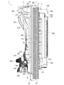
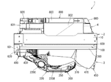
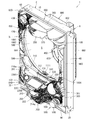
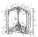
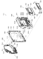
本発明の一実施形態であるパチンコ機1について、図面を参照して詳細に説明する。まず、図1乃至図9を参照して本実施形態のパチンコ機1の全体構成について説明する。図1は本発明の一実施形態であるパチンコ機の正面図である。図2はパチンコ機の右側面図であり、図3はパチンコ機の平面図であり、図4はパチンコ機の背面図である。図5はパチンコ機を前から見た斜視図であり、図6はパチンコ機を後ろから見た斜視図である。図7は本体枠から扉枠3を開放させると共に、外枠2から本体枠4を開放させた状態で前から見たパチンコ機の斜視図である。図8はパチンコ機を扉枠3、遊技盤5、本体枠4、及び外枠2に分解して前から見た分解斜視図であり、図9はパチンコ機を扉枠3、遊技盤5、本体枠4、及び外枠2に分解して後ろから見た分解斜視図である。
[1. Overall structure of pachinko machine]
A
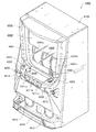
本実施形態のパチンコ機1は、遊技ホールの島設備(図示しない)に設置される枠状の外枠2と、外枠2の前面を開閉可能に閉鎖する扉枠3と、扉枠3を開閉可能に支持していると共に外枠2に開閉可能に取付けられている本体枠4と、本体枠4に前側から着脱可能に取付けられると共に扉枠3を通して遊技者側から視認可能とされ遊技者によって遊技球が打込まれる遊技領域5aを有した遊技盤5と、を備えている。
A
パチンコ機1の外枠2は、図8及び図9等に示すように、上下に離間しており左右に延びている上枠部材10及び下枠部材20と、上枠部材10及び下枠部材20の両端同士を連結しており上下に延びている左枠部材30及び右枠部材40と、を備えている。上枠部材10、下枠部材20、左枠部材30、及び右枠部材40は、前後の幅が同じ幅に形成されている。また、上枠部材10及び下枠部材20の左右の長さに対して、左枠部材30及び右枠部材40の上下の長さが、長く形成されている。
As shown in FIGS. 8 and 9, the
また、外枠2は、左枠部材30及び右枠部材40の下端同士を連結し下枠部材20の前側に取付けられる幕板部材50と、上枠部材10の正面視左端部側に取付けられている外枠側上ヒンジ部材60と、幕板部材50の正面視左端側上部と左枠部材30とに取付けられている外枠側下ヒンジ部材70と、を備えている。外枠2の外枠側上ヒンジ部材60と外枠側下ヒンジ部材70とによって、本体枠4及び扉枠3が開閉可能に取付けられている。
The
パチンコ機1の扉枠3は、正面視の外形が四角形で前後に貫通している貫通口111を有した枠状の扉枠ベースユニット100と、扉枠ベースユニット100の前面下部に取付けられ遊技球を貯留可能な上皿201及び下皿202を有した皿ユニット200と、扉枠ベースユニット100の前面上部に取付けられるトップユニット350と、扉枠ベースユニット100の前面左部に取付けられる左サイドユニット400と、扉枠ベースユニット100の前面右部に取付けられる右サイドユニット450と、扉枠ベースユニット100の前面右下部に皿ユニット200を貫通して取付けられ上皿201に貯留された遊技球を遊技盤5の遊技領域内へ打込むために遊技者が操作可能なハンドルユニット500と、扉枠ベースユニット100の後面下部に取付けられ遊技領域内へ打ち損じた遊技球を受けて皿ユニット200の下皿202へ排出するファールカバーユニット520と、扉枠ベースユニット100の後面下部に取付けられ上皿201の遊技球を球発射装置680へ送るための球送りユニット540と、扉枠ベースユニット100の後面に取付けられ貫通口111を閉鎖するガラスユニット560と、ガラスユニット560の後面下部を覆う防犯カバー580と、を備えている。
The
パチンコ機1の本体枠4は、一部が外枠2の枠内に挿入可能とされると共に遊技盤5の外周を支持可能とされた枠状の本体枠ベース600と、本体枠ベース600の正面視左側の上下両端に取付けられ外枠2の外枠側上ヒンジ部材60及び外枠側下ヒンジ部材70に夫々回転可能に取付けられると共に扉枠3の扉枠側上ヒンジ部材140及び扉枠側下ヒンジ部材150が夫々回転可能に取付けられる本体枠側上ヒンジ部材620及び本体枠側下ヒンジ部材640と、本体枠ベース600の正面視左側面に取付けられる補強フレーム660と、本体枠ベース600の前面下部に取付けられており遊技盤5の遊技領域5a内に遊技球を打込むための球発射装置680と、本体枠ベースの正面視右側面に取付けられており外枠2と本体枠4、及び扉枠3と本体枠4の間を施錠する施錠ユニット700と、本体枠ベース600の正面視上辺及び左辺に沿って後側に取付けられており遊技者側へ遊技球を払出す逆L字状の払出ユニット800と、本体枠ベース600の後面下部に取付けられている基板ユニット900と、本体枠ベース600の後側に開閉可能に取付けられ本体枠ベース600に取付けられた遊技盤5の後側を覆う裏カバー980と、を備えている。
The
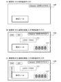
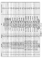
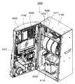
裏カバー980の内部には、パチンコ機1で行われる遊技の進行にかかる制御を行う主制御ユニット1300が設けられる。主制御ユニット1300には役物比率表示器1317が設けられる。役物比率表示器1317は、例えば、4桁の7セグメントLEDによって構成される。液晶表示装置によって役物比率表示器1317を構成してもよい。なお、役物比率表示器1317を主制御ユニット1300ではなく、払出制御基板ユニット950に設けられてもよい。
Inside the
また、役物比率を表示する表示装置を別に設けず、液晶表示装置1600、3114、244に役物比率を表示してもよい。この場合、液晶表示装置1600、3114、244のいずれかに役物比率を常時表示すると、役物比率を遊技者に報知でき、遊技者がパチンコ機の調子を確認できてよい。
Further, the accessory ratio may be displayed on the liquid
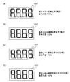
役物比率は、後述するように、役物獲得球数÷総獲得球数で計算でき、例えば役物比率の数値が高い(例えば、90%)のパチンコ機は、大当たりによって多くの賞球が得られているので、調子がよいといえる。一方、役物比率の数値が低い(例えば、10%)のパチンコ機は、大当たり遊技が少なく、大当たり中の賞球が少ないので、調子が悪いといえる。したがって、遊技者は、役物比率の数値を考慮して、遊技するパチンコ機を選択できる。 As will be described later, the ratio of the winning combination can be calculated by the number of winning balls divided by the total number of acquired balls. For example, a pachinko machine with a high value of the winning ratio (for example, 90%) has many winning balls depending on the jackpot. Since it is obtained, it can be said that it is in good condition. On the other hand, a pachinko machine with a low value of an accessory ratio (for example, 10%) can be said to be in a bad condition because there are few jackpot games and few winning balls in the jackpot. Therefore, the player can select a pachinko machine to play in consideration of the numerical value of the accessory ratio.
遊技者に役物比率を報知する態様として、役物比率の数値をメイン液晶表示装置1600に表示してもよい。例えば、役物比率が70%以上の場合は赤色で数値を表示し、枠ランプを赤点灯または点滅し、69%〜30%の場合は緑色で数値を表示し、枠ランプを緑点灯または点滅する。役物比率の数値は、装飾図柄と間違えないような態様で表示するとよい。例えば、変動していないときの装飾図柄の表示位置と重ならない位置に表示したり、役物比率を示す数字の大きさを装飾図柄より小さくするなどの態様で表示するとよい。表示態様は何段階に分けてもよい。
As a mode for notifying the player of the bonus rate, the numeric value of the bonus rate may be displayed on the main liquid
また、役物比率の数値によってメイン液晶表示装置1600に表示される装飾図柄の態様を変えて、役物比率を遊技者に報知してもよい。例えば、役物比率が70%以上の場合は赤色で装飾図柄を表示し、枠ランプを赤点灯または点滅し、69%〜30%の場合は緑色で装飾図柄を表示し、枠ランプを緑点灯または点滅する。表示態様は何段階に分けてもよい。
Further, the player may be informed of the accessory ratio by changing the decorative pattern displayed on the main liquid
また、扉枠3に備わる液晶表示装置244に表示してもよい。その際、上述した表示態様を変えてもよいし、役物比率だけでなく、他の情報とともに表示してもよい。他の情報とは、大当たり回数や大当たりの連続回数(所謂、連チャン回数)や持ち球数、残り残金などである。
Further, it may be displayed on the liquid
また、役物比率に限らず、後述する連続役物比率やベース値などを、前述したように態様を変化させて表示してもよい。役物比率、連続役物比率、ベース値は、各々表示態様を変えてもよい。 Further, not only the accessory ratio, but also a continuous accessory ratio and a base value, which will be described later, may be displayed by changing the mode as described above. The display mode of the combination ratio, the continuous combination ratio, and the base value may be changed.
主制御ユニット1300は、図13に示すように、一度閉めたら破壊せずに開けることができない構造で封印された透明の樹脂製の主制御基板ボックス1320に封入されており、プリント基板上に配置された部品を外部から見ることができる。さらに、例えば、裏カバー980が透明な樹脂で形成されている場合、パチンコ機1の裏面側から主制御ユニット1300を見ることができ、主制御ユニット1300に設けられる役物比率表示器1317をパチンコ機1の裏面側から見ることができる。役物比率表示器1317を主制御基板ボックス1320内に封入することによって、遊技機1の射幸性を低く見せるための役物比率表示器1317の不正な改造を防止でき、遊技機1の正確な射幸性を表示できる。
As shown in FIG. 13, the
なお、裏カバー980が不透明な樹脂で形成されている場合、役物比率表示器1317の位置の裏カバー980に穴を開けたり、役物比率表示器1317の位置を透明にすることによって、パチンコ機1の裏面側から役物比率表示器1317を見られるようにしてもよい。
When the
また、裏カバー980が透明な樹脂で形成されている場合でも、役物比率表示器1317の位置の裏カバー980の表面を平坦に形成したり、裏カバー980を薄く形成することによって、役物比率表示器1317をパチンコ機1の裏面側から見やすくしてもよい。
Even when the
パチンコ機1の裏面下方には、アウト口1111や入賞口2001、2005、2006などを経由して遊技領域5aから流出した遊技球を集合し、パチンコ機1の外部に排出する排出口が設けられている。なお、排出口から排出された遊技球は、島設備を通じて球タンク802に供給される。本実施例のパチンコ機1には、排出口から排出される遊技球を検出する排出球センサ3060を設ける。
Below the back surface of the
図13に示すように、主制御ユニット1300には役物比率表示スイッチ1318が設けられる。主制御基板ボックス1320には、役物比率表示スイッチ1318が操作可能な穴が設けられる。役物比率表示スイッチ1318の近傍のプリント基板上又は主制御基板ボックス1320に、役物比率の表示を操作するためのスイッチであることを表示(印刷、刻印、シールなど)するとよい。なお、役物比率表示スイッチ1318は、役物比率表示器1317の近くに設けることが望ましいが、主制御ユニット1300ではなくても、操作が容易な場所であれば、他の基板(例えば、演出制御基板4700、電源装置4112)や筐体4100や前面部材4200に設けてもよい。周辺制御ユニット1500や、主制御ユニット1300とは別体で設けられた中継基板や、枠側の電源基板ボックス930内の電源基板や、払出制御基板ユニット950に設けられてもよい。また、後述するように、役物比率表示スイッチ1318はRAMクリアスイッチと兼用してもよい。役物比率表示スイッチ1318を遊技者が操作できない位置に設けることで、遊技者が誤って操作することを防止できる。
As shown in FIG. 13, the
本体枠4の払出ユニット800は、本体枠ベース600の後側に取付けられる逆L字状の払出ユニットベース801と、払出ユニットベース801の上部に取付けられており上方へ開放された左右に延びた箱状で図示しない島設備から供給される遊技球を貯留する球タンク802と、球タンク802の下側で払出ユニットベース801に取付けられており球タンク802内の遊技球を正面視左方向へ誘導する左右に延びたタンクレール803と、払出ユニットベース801における正面視左側上部の後面に取付けられタンクレール803からの遊技球を蛇行状に下方へ誘導する球誘導ユニット820と、球誘導ユニット820の下側で払出ユニットベース801から着脱可能に取付けられており球誘導ユニット820により誘導された遊技球を払出制御基板ユニット950に収容された払出制御基板951(図17を参照)からの指示に基づいて一つずつ払出す払出装置830と、払出ユニットベース801の後面に取付けられ払出装置830によって払出された遊技球を下方へ誘導すると共に皿ユニット200における上皿201での遊技球の貯留状態に応じて遊技球を通常放出口又は満タン放出口の何れかから放出させる上部満タン球経路ユニット850と、払出ユニットベース801の下端に取付けられ上部満タン球経路ユニット850の通常放出口から放出された遊技球を前方へ誘導して前端から扉枠3の貫通球通路526へ誘導する通常誘導路及び満タン放出口から放出された遊技球を前方へ誘導して前端から扉枠3の満タン球受口530へ誘導する満タン誘導路を有した下部満タン球経路ユニット860と、を備えている。
The
本体枠4の基板ユニット900は、本体枠ベース600の後側に取付けられる基板ユニットベース910と、基板ユニットベース910の正面視左側で本体枠ベース600の後側に取付けられ内部に低音用のスピーカ921を有したスピーカユニット920と、基板ユニットベース910の後側で正面視右側に取付けられ内部に電源基板が収容されている電源基板ボックス930と、スピーカユニット920の後側に取付けられており内部にインターフェイス制御基板が収容されているインターフェイス制御基板ボックス940と、電源基板ボックス930及びインターフェイス制御基板ボックス940に跨って取付けられており内部に遊技球の払出しを制御する払出制御基板951が収容された払出制御基板ユニット950と、を備えている。
The
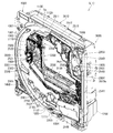
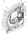
パチンコ機1の遊技盤5は、図8及び図9等に示すように、遊技球が打込まれる遊技領域5aの外周を区画し球発射装置680から発射された遊技球を遊技領域5aの上部に案内する外レール1001及び内レール1002を有した前構成部材1000と、前構成部材1000の後側に取付けられると共に遊技領域5aの後端を区画する平板状の遊技パネル1100と、遊技パネル1100の後側の下部に取付けられており上方に開放された箱状の基板ホルダ1200と、基板ホルダ1200の後側に取付けられておりパチンコ機1の遊技を制御するための主制御基板1310を有している主制御ユニット1300と、遊技パネル1100の前側で遊技領域5a内に取付けられ遊技領域5a内に打込まれた遊技球を受入可能な複数の入賞口を有した表ユニット(図示は省略)と、基板ホルダ1200の上側で遊技パネル1100の後側に取付けられている裏ユニット3000と、を備えている。
As shown in FIGS. 8 and 9, etc., the
本実施形態のパチンコ機1は、上皿201に遊技球を貯留した状態で、遊技者がハンドルレバー504を回転操作すると、球発射装置680によってハンドルレバー504の回転角度に応じた強さで遊技球が遊技盤5の遊技領域5a内へ打込まれる。そして、遊技領域5a内に打込まれた遊技球が、図示しない入賞口に受入れられると、受入れられた入賞口に応じて、所定数の遊技球が払出装置830によって上皿201に払出される。この遊技球の払出しによって遊技者の興趣を高めることができるため、上皿201内の遊技球を遊技領域5a内へ打込ませることができ、遊技者に遊技を楽しませることができる。
In the
[2.遊技盤の全体構成]
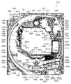
次に、パチンコ機1の遊技盤5の全体構成について、図10乃至図16を参照して詳細に説明する。図10は、遊技盤の正面図である。図11は遊技盤を右前から見た斜視図であり、図12は遊技盤を左前から見た斜視図であり、図13は遊技盤を後ろから見た斜視図である。また、図14は遊技盤を主な構成毎に分解して前から見た分解斜視図であり、図15は遊技盤を主な構成毎に分解して後ろから見た分解斜視図である。更に、図16は、遊技盤における前構成部材及び表ユニットを遊技領域内の前後方向の略中央で切断した正面図である。
[2. Overall configuration of game board]
Next, the overall configuration of the
本実施形態の遊技盤5は、遊技者がハンドルユニット500のハンドルレバー504を操作することで遊技球が打込まれる遊技領域5aを有している。また、遊技盤5は、遊技領域5aの外周を区画し外形が正面視略四角形状とされた前構成部材1000と、前構成部材1000の後側に取付けられており遊技領域5aの後端を区画する板状の遊技パネル1100と、遊技パネル1100の後側下部に取付けられている基板ホルダ1200と、基板ホルダ1200の後面に取付けられており遊技球を遊技領域5a内へ打込むことで行われる遊技内容を制御する主制御基板1310(図17を参照)を有している主制御ユニット1300と、を備えている。遊技パネル1100の前面において遊技領域5a内となる部位には、遊技球と当接する複数の障害釘が所定のゲージ配列で植設されている(図示は省略)。
The
また、遊技盤5は、主制御基板1310からの制御信号に基づいて遊技状況を表示し前構成部材1000の左下隅に遊技者側へ視認可能に取付けられている機能表示ユニット1400と、遊技パネル1100の後側に取付けられている周辺制御ユニット1500と、正面視において遊技領域5aの中央に配置されており所定の演出画像を表示可能なメイン液晶表示装置1600と、遊技パネル1100の前面に取付けられる表ユニット2000と、遊技パネル1100の後面に取付けられる裏ユニット3000と、を更に備えている。裏ユニット3000の後面にメイン液晶表示装置1600が取付けられていると共に、メイン液晶表示装置1600の後面に周辺制御ユニット1500が取付けられている。
In addition, the
遊技パネル1100は、外周が枠状の前構成部材1000の内周よりもやや大きく形成されていると共に透明な平板状のパネル板1110と、パネル板1110の外周を保持しており前構成部材1000の後側に取付けられると共に後面に裏ユニット3000が取付けられる枠状のパネルホルダ1120と、を備えている。
The
表ユニット2000は、遊技領域5a内に打込まれた遊技球を受入可能に常時開口している複数の一般入賞口2001と、複数の一般入賞口2001とは遊技領域5a内の異なる位置で遊技球を受入可能に常時開口している第一始動口2002と、遊技領域5a内の所定位置に取付けられており遊技球の通過を検知するゲート部2003と、遊技球がゲート部2003を通過することにより抽選される普通抽選結果に応じて遊技球の受入れが可能となる第二始動口2004と、第一始動口2002又は第二始動口2004への遊技球の受入れにより抽選される第一特別抽選結果又は第二特別抽選結果に応じて遊技球の受入れが何れかにおいて可能となる第一大入賞口2005及び第二大入賞口2006と、を備えている。第二大入賞口2006は、遊技球が流通する一つの流路に配置された第二上大入賞口2006aと第二下大入賞口2006bとの二つの大入賞口により構成されている(図16を参照)。
The
また、表ユニット2000は、遊技領域5a内の左右方向中央でアウト口1111の直上に取付けられており第一始動口2002及び第一大入賞口2005を有している始動口ユニット2100と、始動口ユニット2100の正面視左方で内レール1002に沿って取付けられており三つの一般入賞口2001を有しているサイドユニット下2200と、サイドユニット下2200の正面視左端上方に取付けられているサイドユニット上2300と、遊技領域5a内の略中央に取付けられており一つの一般入賞口2001、ゲート部2003、第二始動口2004、及び第二大入賞口2006を有している枠状のセンター役物2500と、を備えている。
In addition, the
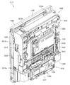
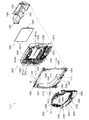
裏ユニット3000は、パネルホルダ1120の後面に取付けられ前方が開放されている箱状で後壁に四角い開口部3010aを有している裏箱3010と、裏箱3010内の所定位置に配置されており表ユニット2000の一般入賞口2001に受入れられた遊技球を検知する複数の一般入賞口センサ3015と、裏箱3010の後面に取付けられておりメイン液晶表示装置1600を着脱可能に取付けるためのロック機構3020と、裏箱3010内の正面視右端に取付けられておりセンター役物2500の一般入賞口2001や第二始動口2004に受入れられた遊技球を排出するための右球通路ユニット3030と、裏箱3010内の正面視右下隅の前端付近に取付けられておりセンター役物2500の第二大入賞口2006や第二アウト口2543cに受入れられた遊技球を排出するための右下球通路ユニット3035と、を備えている。
The
また、裏ユニット3000は、裏箱3010の後面に取付けられている上中継基板3040と、上中継基板3040の後側を覆う上中継基板カバー3041と、裏箱3010の後面に回動可能に取付けられている箱状の演出駆動基板ボックス3042と、演出駆動基板ボックス3042内に収容されている演出駆動基板3043と、裏箱3010の後面に取付けられているパネル中継基板3044と、パネル中継基板3044の後側を覆うパネル中継基板カバー3045と、を備えている。
Further, the
更に、裏ユニット3000は、裏箱3010内の前端で正面視左辺側の上下方向中央から上寄りに取付けられている裏左中装飾ユニット3050と、裏箱3010内における開口部3010aの下方で裏箱3010の後壁付近に取付けられている裏下後可動演出ユニット3100と、裏箱3010内における開口部3010aの上方で正面視左側に取付けられている裏上左可動演出ユニット3200と、裏箱3010内で開口部3010aの正面視左側に取付けられている裏左可動演出ユニット3300と、裏箱3010内における開口部3010aの上方で左右方向中央から正面視右端までにかけて取付けられている裏上中可動演出ユニット3400と、裏箱3010内における開口部3010aの下方で裏下後可動演出ユニット3100の前方に取付けられている裏下前可動演出ユニット3500と、を備えている。
Further, the
[2−1.前構成部材]
次に、前構成部材1000について、主に図14及び図15を参照して説明する。前構成部材1000は、正面視の外形が略正方形とされ、内形が略円形状に前後方向へ貫通しており、内形の内周によって遊技領域5aの外周を区画している。この前構成部材1000は、正面視で左右方向中央から左寄りの下端から時計回りの周方向へ沿って円弧状に延び正面視左右方向中央上端を通り過ぎて右斜め上部まで延びた外レール1001と、外レール1001に略沿って前構成部材1000の内側に配置され正面視左右方向中央下部から正面視左斜め上部まで円弧状に延びた内レール1002と、内レール1002の下端の正面視右側で遊技領域5aの最も低くなった位置に形成されており後方へ向かって低くなるように傾斜しているアウト誘導部1003と、を備えている。
[2-1. Previous component]
Next, the
また、前構成部材1000は、アウト誘導部1003の正面視右端から前構成部材1000の右辺付近まで右端側が僅かに高くなるように直線状に傾斜している右下レール1004と、右下レール1004の右端から前構成部材1000の右辺に沿って外レール1001の上端の下側まで延びており上部が前構成部材1000の内側へ湾曲している右レール1005と、右レール1005の上端と外レール1001の上端とを繋いでおり外レール1001に沿って転動して来た遊技球が当接する衝止部1006と、を備えている。
Further, the
また、前構成部材1000は、内レール1002の上端に回動可能に軸支され、外レール1001との間を閉鎖するように内レール1002の上端から上方へ延出した閉鎖位置と正面視時計回りの方向へ回動して外レール1001との間を開放した開放位置との間でのみ回動可能とされると共に閉鎖位置側へ復帰するように図示しないバネによって付勢された逆流防止部材1007を、備えている。
Further, the
レール1001、1002の出口付近(望ましくは、逆流防止部材1007を通過した直後)の遊技盤5の裏面側には、遊技領域5aに打ち込まれた遊技球を検出する発射球センサ1020を設ける。例えば、発射球センサ1020は、磁気センサで構成し、逆流防止部材1007を通過して遊技領域5aに流入した遊技球を検出すると、信号を出力する。なお、発射球センサ1020は、遊技領域内で遊技球が必ず通過する位置に設けてもよい。遊技盤5における発射球センサ1020の位置を固定化することによって、複数機種間で仕様を共通化でき、製造現場での検査やホールでの設置後検査が容易になる。
On the back side of the
また、レール1001、1002の出口付近などの遊技領域5aの上流に設けた発射球センサ1020は、入賞口センサが遊技球の入賞を検出する前にアウト球を検出する。すなわち、アウト球、賞球の順で遊技球を検出するので、アウト球として計数されていない遊技球に起因した賞球を検出せず、正確にベース値を計算できる。
Further, the
[2−2.遊技パネル]
次に、遊技パネル1100について、主に図14及び図15を参照して説明する。遊技パネル1100は、外周が枠状の前構成部材1000の内周よりもやや大きく形成されていると共に透明な合成樹脂で形成されている平板状のパネル板1110と、パネル板1110の外周を保持しており前構成部材1000の後側に取付けられると共に後面に裏ユニット3000が取付けられる枠状のパネルホルダ1120と、を備えている。遊技パネル1100のパネル板1110は、遊技領域5a内において最も低い位置となる部位に前後に貫通しているアウト口1111が形成されている。また、パネル板1110には、前後に貫通しており表ユニット2000を取付けるための開口部1112が複数形成されている。
[2-2. Game panel]
Next, the
遊技パネル1100のパネルホルダ1120は、パネル板1110を後側から着脱可能に保持している。また、パネルホルダ1120は、裏ユニット3000を取付けるための取付孔と、位置決め孔とが後面に複数形成されている。
The
遊技パネル1100を前構成部材1000の後側に取付けた状態では、前構成部材1000のアウト誘導部1003の後側にパネル板1110のアウト口1111が開口した状態となる。これにより、遊技領域5aの下端へ流下した遊技球が、アウト誘導部1003によって後側のアウト口1111へ誘導され、アウト口1111を通って遊技パネル1100の後側へ排出される。
In a state where the
[2−3.基板ホルダ]
次に、基板ホルダ1200について、図11乃至図15を参照して説明する。基板ホルダ1200は、上方及び前方が開放された横長の箱状に形成されており、底面が左右方向中央へ向かって低くなるように傾斜している。この基板ホルダ1200は、遊技盤5に組立てた状態では、遊技パネル1100の後側に取付けられている裏ユニット3000の下部を下側から覆うことができる。これにより、アウト口1111を通って遊技パネル1100の後側へ排出された遊技球、及び、表ユニット2000及び裏ユニット3000から下方へ排出された遊技球、を全て受けることができ、底面に形成された排出部1201(図14を参照)から下方へ排出させることができる。
[2-3. Substrate holder]
Next, the
[2−4.主制御基板ユニット]
次に、主制御ユニット1300について、図11乃至図15、及び図17を参照して説明する。主制御ユニット1300は、基板ホルダ1200の後面に着脱可能に取付けられている。この主制御ユニット1300は、遊技内容及び遊技球の払出し等を制御する主制御基板1310と、主制御基板1310を収容しており基板ホルダ1200に取付けられる主制御基板ボックス1320と、を備えている。
[2-4. Main control board unit]
Next, the
主制御基板ボックス1320は、複数の封印機構を備えており、一つの封印機構を用いて主制御基板ボックス1320を閉じると、次に、主制御基板ボックス1320を開けるためにはその封印機構を破壊する必要があり、主制御基板ボックス1320の開閉の痕跡を残すことができる。従って、開閉の痕跡を見ることで、主制御基板ボックス1320の不正な開閉を発見することができ、主制御基板1310への不正行為に対する抑止力が高められている。
The main
[2−5.機能表示ユニット]
次に、機能表示ユニット1400について、図10乃至図12を参照して説明する。機能表示ユニット1400は、図示するように、遊技領域5aの外側で前構成部材1000の左下隅に取付けられている。この機能表示ユニット1400は、遊技盤5をパチンコ機1に組立てた状態で、扉枠3の貫通口111を通して前方(遊技者側)から視認することができる(図1を参照)。この機能表示ユニット1400は、主制御基板1310からの制御信号に基づき複数のLEDを用いて、遊技状態(遊技状況)や、普通抽選結果や特別抽選結果等を表示するものである。
[2-5. Function display unit]
Next, the
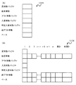
機能表示ユニット1400は、詳細な図示は省略するが、遊技状態を表示する一つのLEDからなる状態表示器と、ゲート部2003に対する遊技球の通過により抽選される普通抽選結果に基づいて二つのLEDを点滅制御することにより普通図柄を変動表示した後にこれら二つのLEDを普通抽選結果に応じた点灯態様で表示させる普通図柄表示器と、ゲート部2003に対する遊技球の通過に係る普通図柄の変動表示のうち未だ変動表示の開始条件が成立していない変動表示の個数である保留数を表示する二つのLEDからなる普通保留表示器と、第一始動口2002への遊技球の受入れ(始動入賞の発生)により抽選された第一特別抽選結果に基づいて八つのLEDを点滅制御することにより第一特別図柄を変動表示した後にこれら八つのLEDを第一特別抽選結果に応じた点灯態様で表示させる第一特別図柄表示器と、第一始動口2002への遊技球の受入れに係る第一特別図柄の変動表示のうち未だ変動表示の開始条件が成立していない変動表示の個数である保留数を表示する二つのLEDからなる第一特別保留数表示器と、第二始動口2004への遊技球の受入れ(始動入賞の発生)により抽選された第二特別抽選結果に基づいて八つのLEDを点滅制御することにより第二特別図柄を変動表示した後にこれら八つのLEDを第二特別抽選結果に応じた点灯態様で表示させる第二特別図柄表示器と、第二始動口2004への遊技球の受入れに係る第二特別図柄の変動表示のうち未だ変動表示の開始条件が成立していない変動表示の個数である保留数を表示する二つのLEDからなる第二特別保留数表示器と、第一特別抽選結果又は第二特別抽選結果が「大当り」等の時に、第一大入賞口2005や第二大入賞口2006の開閉パターンの繰返し回数(ラウンド数)を表示する二つのLEDからなるラウンド表示器と、を主に備えている。
Although detailed illustration is omitted, the
この機能表示ユニット1400では、備えられているLEDを、適宜、点灯、消灯、及び、点滅、等させることにより、保留数や図柄等を表示することができる。
In this
[2−6.周辺制御ユニット]
次に、周辺制御ユニット1500について、図13及び図15を参照して説明する。周辺制御ユニット1500は、裏ユニット3000の裏箱3010の後面に取付けられている。周辺制御ユニット1500は、主制御基板1310からの制御信号に基づいて遊技者に提示する演出を制御する周辺制御基板1510(図17を参照)と、周辺制御基板1510を収容している周辺制御基板ボックス1520と、を備えている。周辺制御基板1510は、発光演出、サウンド演出、及び可動演出、等を制御するための周辺制御部1511と、演出画像を制御するための液晶表示制御部1512と、を備えている(図17を参照)。
[2-6. Peripheral control unit]
Next, the
[2−7.メイン液晶表示装置]
次に、メイン液晶表示装置1600について、図10乃至図16を参照して説明する。メイン液晶表示装置1600は、正面視において遊技領域5aの中央に配置されており、遊技パネル1100の後側に裏ユニット3000の裏箱3010を介して取付けられている。詳述すると、メイン液晶表示装置1600は、裏箱3010の後壁の略中央の後面に対して、着脱可能に取付けられている。このメイン液晶表示装置1600は、遊技盤5を組立てた状態で、枠状のセンター役物2500の枠内を通して、前側(遊技者側)から視認することができる。このメイン液晶表示装置1600は、白色LEDをバックライトとしたフルカラーの表示装置であり、静止画像や動画を表示することができる。
[2-7. Main liquid crystal display]
Next, the main liquid
メイン液晶表示装置1600は、図14及び図15に示すように、正面視左側面から外方へ突出している二つの左固定片1601と、正面視右側面から外方へ突出している右固定片1602と、を備えている。このメイン液晶表示装置1600は、液晶画面を前方へ向けた状態で、後述する裏箱3010の枠状の液晶取付部内の正面視左内周面に開口している二つの固定溝3010cに、裏箱3010の斜め後方から二つの左固定片1601を挿入した上で、右固定片1602側を前方へ移動させて、右固定片1602をロック機構3020の開口部内に挿入し、ロック機構3020を下方へスライドさせることにより、裏箱3010に取付けられる。
As shown in FIGS. 14 and 15, the main liquid
[2−8.表ユニットの全体構成]
次に、表ユニット2000について、主に図10乃至図12、図14乃至図16を参照して説明する。遊技盤5の表ユニット2000は、遊技パネル1100のパネル板1110に、前方から取付けられており、前端がパネル板1110の前面よりも前方へ突出していると共に、後端が開口部1112を貫通してパネル板1110の後面よりも後方へ突出している。本実施形態の表ユニット2000は、遊技領域5a内に打込まれた遊技球を受入可能としており常時開口している複数の一般入賞口2001と、複数の一般入賞口2001とは遊技領域5a内の異なる位置で遊技球を受入可能に常時開口している第一始動口2002と、遊技領域5a内の所定位置に取付けられており遊技球の通過を検知するゲート部2003と、遊技球がゲート部2003を通過することにより抽選される普通抽選結果に応じて遊技球の受入れが可能となる第二始動口2004と、第一始動口2002又は第二始動口2004への遊技球の受入れにより抽選される第一特別抽選結果又は第二特別抽選結果に応じて何れかにおいて遊技球の受入れが可能となる第一大入賞口2005及び第二大入賞口2006と、を備えている。
[2-8. Overall configuration of table unit]
Next, the
複数(ここでは四つ)の一般入賞口2001は、三つが遊技領域5a内の下部に配置されており、残りの一つが遊技領域5a内における正面視右上付近に配置されている。第一始動口2002は、遊技領域5a内の左右方向中央でアウト口1111の直上に配置されている。ゲート部2003は、遊技領域5a内における正面視右上で衝止部1006の略直下に配置されている。第二始動口2004は、ゲート部2003の直下から正面視右寄りに配置されている。上述した複数の一般入賞口2001のうち遊技領域5a内の正面視右上付近に配置されている一般入賞口2001は、第二始動口2004の直上に配置されている。第一大入賞口2005は、第一始動口2002とアウト口1111との間に配置されている。第二大入賞口2006は、第一始動口2002の正面視右方で第一大入賞口2005よりも上方に配置されている。
A plurality (four in this case) of general winning
表ユニット2000における第二大入賞口2006は、図16に示すように、遊技球が流通する一つの流路に沿って配置された第二上大入賞口2006aと第二下大入賞口2006bとにより構成されている。第二大入賞口2006は、第二上大入賞口2006aが遊技領域5a内における正面視右下付近に配置されており、第二下大入賞口2006bが第二上大入賞口2006aの正面視左側で下方に配置されている。
As shown in FIG. 16, the second
また、表ユニット2000は、遊技領域5a内の左右方向中央でアウト口1111の直上に取付けられており第一始動口2002及び第一大入賞口2005を有している始動口ユニット2100と、始動口ユニット2100の正面視左方で内レール1002に沿って取付けられており三つの一般入賞口2001を有しているサイドユニット下2200と、サイドユニット下2200の正面視左端上方に取付けられているサイドユニット上2300と、遊技領域5a内の略中央に取付けられており一つの一般入賞口2001、ゲート部2003、第二始動口2004、及び第二大入賞口2006を有している枠状のセンター役物2500と、を備えている。
In addition, the
[2−8a.始動口ユニット]
次に、表ユニット2000の始動口ユニット2100について、説明する。始動口ユニット2100は、遊技領域5a内において、左右方向中央の下端部付近でアウト口1111の直上に配置されており、パネル板1110に前方から取付けられている。この始動口ユニット2100は、第一始動口2002及び第一大入賞口2005を有している。
[2-8a. Starting port unit]
Next, the
始動口ユニット2100は、パネル板1110の前面に取付けられ左右に延びた矩形状で前後に貫通している第一大入賞口2005を有した平板状のユニットベース2101と、ユニットベース2101における第一大入賞口2005の上方で左右方向略中央の上部から前方へ突出しており第一始動口2002を形成している球受部2102と、ユニットベース2101の後側に取付けられており第一始動口2002に受入れられた遊技球を下方へ誘導する球誘導部2103と、球誘導部2103に取付けられており第一始動口2002に受入れられた遊技球を検知する第一始動口センサ2104と、第一大入賞口2005を閉鎖するようにユニットベース2101の後面に取付けられている第一アタッカユニット2110と、を備えている。
The starting
始動口ユニット2100の第一アタッカユニット2110は、第一大入賞口2005を後方から閉鎖するようにユニットベース2101の後面に取付けられ前端が第一大入賞口2005と略同じ大きさで前方に開放されている箱状のユニットケース2111と、第一大入賞口2005を開閉可能にユニットケース2111の前端で下辺が回動可能に支持されている横長矩形状で平板状の第一大入賞口扉部材2112と、ユニットケース2111内に取付けられており第一大入賞口扉部材2112を開閉駆動させる第一アタッカソレノイド2113と、ユニットケース2111内に取付けられており第一大入賞口2005に受入れられた遊技球を検知する第一大入賞口センサ2114と、ユニットケース2111の上面に取付けられており第一始動口センサ2104、第一アタッカソレノイド、及び第一大入賞口センサ2114と主制御基板1310との接続を中継する始動口ユニット中継基板2115と、ユニットケース2111の下部に取付けられており第一大入賞口2005を発光装飾させるための始動口ユニット装飾基板(図示は省略)と、を備えている。
The first attacker unit 2110 of the
第一始動口2002を形成している球受部2102は、遊技球を一度に一つのみ受入可能な大きさで上方に向かって開口している。ユニットベース2101を貫通している第一大入賞口2005は、遊技球を一度に複数(例えば、4個〜6個)受入可能な大きさで前方に向かって開口している。
The
始動口ユニット2100は、球受部2102により形成されている第一始動口2002が上方に向かって開口しており、第一始動口2002に受入れられた遊技球を、球誘導部2103によりユニットベース2101の後側で下方へ誘導し、第一始動口センサ2104に検知させた後に、第一アタッカユニット2110を貫通して下方へ排出させることができる。本実施形態では、第一始動口センサ2104が二つ備えられており、主制御基板1310では、所定の時間範囲内で二つの第一始動口センサ2104が遊技球を検知すると、第一始動口2002に遊技球が受入れられたと判断するようになっている。これにより、第一始動口2002への不正な工具の挿入による不正行為を検知することができる。
The
始動口ユニット2100では、ユニットベース2101の後面に第一アタッカユニット2110を取付けることにより、第一アタッカユニット2110の第一大入賞口扉部材2112が、ユニットベース2101に開口している第一大入賞口2005内に後方から挿入されて、第一大入賞口2005を閉鎖している。この第一大入賞口扉部材2112は、第一大入賞口2005を閉鎖している直立した状態で、下辺の左右両端部がユニットケース2111によって回動可能に取付けられており、上辺が前方且つ下方へ移動するように回動させることで第一大入賞口2005を閉状態から開状態とすることができる。
In the
第一アタッカユニット2110の第一大入賞口扉部材2112は、通常の状態(第一アタッカソレノイド2113が非通電の状態)では直立して、第一大入賞口2005を閉鎖している。そして、第一アタッカソレノイド2113が遊技状態に応じて通電されると、上辺が前方且つ下方へ移動するように第一大入賞口扉部材2112が回動して、上辺が下辺よりもやや上方へ位置した状態となる。つまり、第一大入賞口扉部材2112が、第一大入賞口2005の下辺から前方へ向かって高くなるように傾斜した状態となる。
The first big prize opening
この状態で第一大入賞口2005の前方を遊技球が流下して第一大入賞口扉部材2112に当接すると、第一大入賞口扉部材2112の傾斜により遊技球の流通方向が下方から後方へと変化し、第一大入賞口2005に受入れられてユニットケース2111内に進入することとなる。そして、第一大入賞口2005に受入れられた遊技球は、第一大入賞口センサ2114により検知された後に、ユニットケース2111の下面から下方へ排出される。
In this state, when the game ball flows down in front of the first
[3.制御構成]
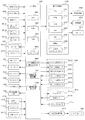
次に、パチンコ機1の各種制御を行う制御構成について、図17を参照して説明する。図17は、パチンコ機の制御構成を概略的に示すブロック図である。パチンコ機1の主な制御構成は、図示するように、遊技盤5に取付けられる主制御基板1310及び周辺制御基板1510と、本体枠4に取付けられる払出制御基板951と、から構成されており、夫々の制御が分担されている。主制御基板1310は、遊技動作(遊技の進行)を制御する。周辺制御基板1510は、主制御基板1310からのコマンドに基いて遊技中の各種演出装置を制御する周辺制御部1511と、周辺制御部1511からのコマンドに基いてメイン液晶表示装置1600や上皿液晶表示装置244等での演出画像の表示を制御する液晶表示制御部1512と、を備えている。払出制御基板951は、遊技球の払出し等を制御する払出制御部952と、ハンドルレバー504の回転操作による遊技球の発射を制御する発射制御部953と、を備えている。
[3. Control configuration]
Next, a control configuration for performing various controls of the
[3−1.主制御基板]
遊技の進行を制御する主制御基板1310は、各種処理プログラムや各種コマンドを記憶するROM1313や一時的にデータを記憶するRAM1312等が内蔵されるマイクロプロセッサである主制御MPU1311と、入出力デバイス(I/Oデバイス)としての主制御I/Oポート1314と、各種検出スイッチからの検出信号が入力される主制御入力回路1315と、各種ソレノイドを駆動するための主制御ソレノイド駆動回路1316と、主制御MPU1311に内蔵されているRAMに記憶された情報を完全に消去するためのRAMクリアスイッチと、を備えている。主制御MPU1311は、その内蔵されたROMやRAMのほかに、その動作(システム)を監視するウォッチドックタイマや不正を防止するための機能等も内蔵されている。
[3-1. Main control board]
The
主制御基板1310の主制御MPU1311は、第一始動口2002に受入れられた遊技球を検出する第一始動口センサ2104、第二始動口2004に受入れられた遊技球を検出する第二始動口センサ2551、一般入賞口2001に受入れられた遊技球を検出する一般入賞口センサ3015、ゲート部2003を通過した遊技球を検知するゲートセンサ2547、第一大入賞口2005に受入れられた遊技球を検知する第一大入賞口センサ2114、第二大入賞口2006としての第二上大入賞口2006a及び第二下大入賞口2006bに受入れられた遊技球を検知する第二上大入賞口センサ2554及び第二下大入賞口センサ2557、排出球センサ3060、発射球センサ1020及び遊技領域5a内における不正な磁気を検知する磁気検出センサ、等からの検出信号が夫々主制御I/Oポート1314を介して入力される。
The
主制御MPU1311は、これらの検出信号に基づいて、主制御I/Oポート1314から主制御ソレノイド駆動回路に制御信号を出力することにより、始動口ソレノイド2550、第一アタッカソレノイド2113、第二上アタッカソレノイド2553、及び第二下アタッカソレノイド2556に駆動信号を出力したり、主制御I/Oポート1314から機能表示ユニット1400の第一特別図柄表示器、第二特別図柄表示器、第一特別図柄記憶表示器、第二特別図柄記憶表示器、普通図柄表示器、普通図柄記憶表示器、遊技状態表示器、ラウンド表示器、等に駆動信号を出力したりする。
Based on these detection signals, the
なお、本実施形態おいて、第一始動口センサ2104、第二始動口センサ2551、ゲートセンサ2547、第一大入賞口センサ2114、第二上大入賞口センサ2554、及び第二下大入賞口センサ2557には、非接触タイプの電磁式の近接スイッチを用いているのに対して、一般入賞口センサ3015には、接触タイプのON/OFF動作式のメカニカルスイッチを用いている。これは、遊技球が、第一始動口2002や第二始動口2004に頻繁に入球すると共に、ゲート部2003を頻繁に通過するため、第一始動口センサ2104、第二始動口センサ2551、及びゲートセンサ2547による遊技球の検出も頻繁に発生する。このため、第一始動口センサ2104、第二始動口センサ2551、及びゲートセンサ2547には、耐久性が高く寿命の長い近接スイッチを用いている。また、遊技者にとって有利となる有利遊技状態(「大当り」遊技、等)が発生すると、第一大入賞口2005や第二大入賞口2006が開放(又は、拡大)されて遊技球が頻繁に入球するため、第一大入賞口センサ2114、第二上大入賞口センサ2554、及び第二下大入賞口センサ2557による遊技球の検出も頻繁に発生する。このため、第一大入賞口センサ2114、第二上大入賞口センサ2554、及び第二下大入賞口センサ2557にも、耐久性が高く寿命の長い近接スイッチを用いている。これに対して、遊技球が頻繁に入球しない一般入賞口2001には、一般入賞口センサ3015による検出も頻繁に発生しない。このため、一般入賞口センサ3015には、近接スイッチより寿命が短いメカニカルスイッチを用いている。
In this embodiment, the first
また、主制御MPU1311は、遊技に関する各種情報(遊技情報)及び払出しに関する各種コマンド等を払出制御基板951に送信したり、この払出制御基板951からのパチンコ機1の状態に関する各種コマンド等を受信したりする。更に、主制御MPU1311は、メイン液晶表示装置1600等で実行される遊技演出の制御に関する各種コマンド及びパチンコ機1の状態に関する各種コマンドを、主制御I/Oポート1314を介して周辺制御基板1510の周辺制御部1511に送信したりする。なお、主制御MPU1311は、払出制御基板951からパチンコ機1の状態に関する各種コマンドを受信すると、これらの各種コマンドを整形して周辺制御部1511に送信する。
Further, the
主制御基板1310には、電源基板ボックス930内の電源基板から各種電圧が供給されている。この主制御基板1310に各種電圧を供給する電源基板は、電源遮断時にでも所定時間、主制御基板1310に電力を供給するためのバックアップ電源としての電気二重層キャパシタ(以下、単に「キャパシタ」と記載する。)を備えている。このキャパシタにより主制御MPU1311は、電源遮断時にでも電源断時処理において各種情報をRAM1312に記憶することができる。この記憶した各種情報は、電源投入時に主制御基板1310のRAMクリアスイッチが操作されると、RAM1312から完全に消去(クリア)される。このRAMクリアスイッチの操作信号(検出信号)は、払出制御基板951にも出力される。
Various voltages are supplied to the
また、主制御基板1310には、停電監視回路が設けられている。この停電監視回路は、電源基板から供給される各種電圧の低下を監視しており、それらの電圧が停電予告電圧以下となると、停電予告として停電予告信号を出力する。この停電予告信号は、主制御I/Oポート1314を介して主制御MPU1311に入力される他に、払出制御基板951等にも出力されている。
The
主制御基板1310には、パチンコ機1の裏面側から視認可能な位置に役物比率表示器1317が取り付けられる。役物比率表示器1317は、主制御MPU1311が計算した役物比率を表示する。
An
また、主制御基板1310には、役物比率表示スイッチ1318が設けられる。役物比率表示スイッチ1318は、モーメンタリ動作をする押ボタンスイッチで構成するとよいが、他の形式のスイッチでもよい。役物比率表示スイッチ1318を操作すると、役物比率表示器1317に役物比率を表示する。なお、役物比率表示器1317は常時、役物比率を表示し、役物比率表示スイッチ1318の操作によって表示内容を切り替えてもよい。
The
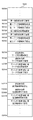
図18は、主制御MPU1311内の構成を示す図である。
FIG. 18 is a diagram showing a configuration within the
主制御MPU1311は、CPU13111、RAM1312、ROM1313、乱数発生回路13112、パラレル入力ポート13113、シリアル通信回路13114、タイマ回路13115、割込コントローラ13116、外部バスインターフェイス13117、クロック回路13118、照合用ブロック13119、固有情報13120、演算回路13121及びリセット回路13122を有する。
The
CPU13111は、ROM1313に記憶されたプログラムを実行する。RAM1312は、プログラム実行時に必要なデータを記憶する。
The
主制御MPU1311には、一つ以上の乱数発生回路13112が設けられている。乱数発生回路13112は、変動表示ゲームの結果(第一特別抽選結果、第二特別抽選結果)の抽選結果や変動表示ゲームの演出内容を決定するための乱数を提供する。
The
パラレル入力ポート13113は、主制御入力回路1315を経由して各種検出スイッチからの検出信号が入力されるポートである。
The
シリアル通信回路13114は、主制御I/Oポート1314を介して、遊技演出の制御に関する各種コマンド及びパチンコ機1の状態に関する各種コマンドを周辺制御基板1510の周辺制御部1511と送受信する。また、シリアル通信回路13114は、主制御I/Oポート1314を介して、遊技に関する各種情報(遊技情報)及び遊技球の払い出しに関する各種コマンド等を払出制御基板951と送受信する。さらに、シリアル通信回路13114は、役物比率を表示するためのデータを役物比率表示器1317に送信する。シリアル通信回路13114の詳細な構成は、図19を参照して後述する。
The
タイマ回路13115は、タイマ割り込みや各種時間制御のためのタイマである。割込コントローラ13116は、CPU13111に対する各種の割り込み(一般割り込み、ソフトウェアでマスク不可能なNMI)を制御する。すなわち、割込コントローラ13116が割り込みを検出した場合、割り込みの種類毎に定められたベクターテーブルを参照し、ベクターテーブルに設定されたアドレスにジャンプする。
The
外部バスインターフェイス13117は、主制御MPU1311の内部バスを外部のデバイスと接続するためのインターフェイスである。外部バスインターフェイス13117からは、I/Oリクエスト(IORQ)、リード(RD)、ライト(WR)、16ビットのアドレス(A0〜A15)、8ビットのデータ(D0〜D7)が入出力できる。
The
クロック回路13118は、入力された外部クロック信号(例えば、32MHz)から主制御MPU1311の内部クロックを生成する。また、クロック回路13118は、入力されたクロック信号に、設定された数の分周をして、CLKO端子から外部に出力する。例えば、役物比率表示器1317のドライバ回路13171(図27参照)に供給するクロック信号を出力してもよい。
The
照合用ブロック13119は、ROM1313が不正に改造されていないかを所定のコードを用いて照合する機能ブロックである。固有情報13120は、主制御MPU1311に固有のIDであり、チップの製造時に書き換え不能に書き込まれている。
The
演算回路13121は、ROM1313に記録されたプログラムによらない演算機能を提供する。この演算機能は、チップの製造時に固定的に書き込まれている。
The
リセット回路13122は、指定外走行禁止回路、ウォッチドッグタイマ及びユーザリセット機能を有する。指定外走行禁止回路は、ROM1313の所定外のアドレスにCPU13111がアクセスした場合、不正なプログラムによるアクセスであると推定し、主制御MPU1311の動作をリセットする。ウォッチドッグタイマは、所定のタイマ時間が経過した際にタイムアウト信号を出力し、主制御MPU1311の動作をリセットする。ユーザリセット機能は、SRST端子に入力されたリセット信号によって、主制御MPU1311の動作をリセットする。
The
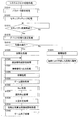
図19は、シリアル通信回路13114の構成を示す図である。
FIG. 19 is a diagram showing a configuration of the
シリアル通信回路13114は、四つのデータ送受信回路を有しており、各データ送受信回路が1チャネル分のデータを所定のデバイスと送受信する。なお、図19では、データ送信回路のみを図示し、データ受信回路(例えば、1チャネル分が実装)の説明は省略する。
The
本実施例の遊技機では、シリアル通信回路13114は、前述したように、周辺制御基板1510との通信に使用されるチャネル0、払出制御基板951との通信に使用されるチャネル1、役物比率表示器1317のドライバ回路13171との通信に使用されるチャネル2の三つのチャネルが使用され、チャネル3は未使用である。
In the gaming machine of this embodiment, as described above, the
シリアル通信回路13114は、データレジスタ3141、送信データレジスタ3142、パリティ生成回路3143、送信用シフトレジスタ3144、コマンドステータスレジスタ3145、通信設定レジスタ3146、送信トリガ設定レベルレジスタ3147、ボーレートレジスタ3148及びボーレート生成回路3149を有する。
The
CPU13111から入力されたデータは、データレジスタ3141に格納された後、送信データレジスタ3142に格納される。送信データレジスタ3142は、所定の容量(例えば、64バイト)のFIFOで構成される。送信データレジスタ3142は、パリティ生成回路3143がデータの送信単位毎に生成した誤り検出符号を、送信すべきデータに付加し、送信用シフトレジスタ3144に格納する。
Data input from the
ボーレート生成回路3149は、クロック回路13118から供給されるクロック信号から、ボーレートレジスタ3148に設定されたレートでデータを送信するための送信用クロック信号を生成する。そして、送信用シフトレジスタ3144は、送信用クロック信号に従って、データを送信する。
The baud
コマンドステータスレジスタ3145は、送信状態を確認するために参照されるレジスタである。
The
通信設定レジスタ3146は、データの送信を制御するためのコマンドを格納する。送信トリガ設定レベルレジスタ3147は、送信データレジスタ3142のFIFOが割り込みを発生させるデータ量を制御するための閾値を格納する。ボーレートレジスタ3148は、データの送信レートを規定するためのボーレートの設定を格納する。通信設定レジスタ3146、送信トリガ設定レベルレジスタ3147及びボーレートレジスタ3148は、図20のステップS28において初期設定として、4チャネルの各々について設定される。
The
以下、これらの設定について詳しく説明する。通信設定レジスタには、各チャネルの通信フォーマットが設定される。具体的には、FIFOの使用の有無(FIFOモード、ノーマルモード)、ストップビットのビット数、パリティ(パリティを使用するか、偶数パリティか奇数パリティか)を設定する。例えば、周辺制御基板1510との通信に使用されるチャネル0及び払出制御基板951との通信に使用されるチャネル1では、FIFOモード、ストップビット=1ビット、偶数パリティを意味する1×××1010Bを設定し、役物比率表示器1317のドライバ回路13171との通信に使用されるチャネル2では、FIFOモード、ストップビット=1ビット、パリティ未使用を意味する1×××1000Bを設定する。
Hereinafter, these settings will be described in detail. A communication format for each channel is set in the communication setting register. Specifically, the presence / absence of use of FIFO (FIFO mode, normal mode), the number of stop bits, and parity (whether parity is used, even parity or odd parity) are set. For example, in
FIFOモードでは、送信データレジスタ3142のFIFOを使用してデータを送信する。また、遊技機はノイズが多い環境にあることから、主制御基板1310の外に高速でデータを送信する際は、パリティを設定することが望ましい。
In the FIFO mode, data is transmitted using the FIFO of the
役物比率表示器1317は主制御基板1310に実装されるので、通信用の電線を経由する他の基板との通信と比較し、ノイズの影響は少ない。また、送受信するデータ量が少ないので、通信速度は低くてよく、パリティを使用する必要性は乏しい。なお、役物比率表示器1317のドライバ回路13171と主制御MPU1311との間で信号を伝達するパターンに沿って(例えば、プリント基板の表面又は内層に設けられた信号線の左右及び/又は厚み方向に隣接する層)にグランドパターンを設け、グランドパターンによるシールド効果によって、当該信号伝達パターンに重畳するノイズを低減できる。
Since the
送信トリガ設定レベルレジスタ3147は、送信データレジスタ3142のFIFOが割り込みを発生させるデータ量を定める。具体的には、送信データレジスタ3142のFIFOに格納されている送信データの量が設定したバイト数より小さい場合、各チャンネルに対応したステータスレジスタの所定ビットがセットされる。ステータスレジスタの当該ビットを判定することによって、送信データレジスタ3142のFIFOに空きがあるか否かを確認でき、送信データレジスタ3142のFIFOに格納されたデータの送信タイミングを判定できる。
The transmission trigger
なお、送信FIFOに異常があるかを判定するために、ステータスレジスタの当該ビットを利用できる。例えば、送信データレジスタ3142のFIFOに所定の期間データが書き込まれない場合でも、ステータスレジスタの当該ビットがセットされない場合、送信データレジスタ3142のFIFOに空きが生じていないことから、送信データレジスタ3142のFIFOからデータが送信されていないと判定して、エラー処理(例えば、エラー報知)を実行してもよい。 Note that the bit of the status register can be used to determine whether there is an abnormality in the transmission FIFO. For example, even if data is not written to the FIFO of the transmission data register 3142 for a predetermined period, if the bit of the status register is not set, the FIFO of the transmission data register 3142 does not have an empty space. Error processing (for example, error notification) may be executed by determining that data is not transmitted from the FIFO.
ボーレートレジスタ3148は、データ送信レートを定める。例えば、周辺制御基板1510との通信に使用されるチャネル0では19200bpsを設定し、払出制御基板951との通信に使用されるチャネル1では1200bpsを設定し、役物比率表示器1317のドライバ回路13171との通信に使用されるチャネル2では1200bpsを設定する。
The
このように、各チャネルで送信されるデータによって送信レートを変えている。これは、遊技機の内部は遊技球が転動しており、遊技機の電子回路はノイズの影響を受けやすい環境下にある。このため、遊技者に付与される利益に直接関係する出球を制御するためのデータは確実に送信されるように、低速で払出制御基板951にデータを送信する。一方、周辺制御基板1510は、送信されるデータ量が多く、出球に関係がないので、高いレートでデータを送信する。また、周辺制御基板1510は、受信したコマンドが異常かを検証しており、異常であると判定した場合、周辺制御基板1510を動作させない又は異常処理(例えば、通信エラー報知)を実行し、コマンドの再送を要求する。そして、再送されたコマンドが正常であると判定された場合、該正常コマンドを用いて周辺制御基板1510の状態が復旧される。このため、周辺制御基板1510との通信は、高いレートでデータを送信できる。さらに、周辺制御基板1510との通信レートを低くすると、始動口の入賞から図柄の変動開始までの遅延を遊技者が認識できるようになり、興趣を低下させる可能性がある。
Thus, the transmission rate is changed according to the data transmitted on each channel. This is because the game ball is rolling inside the gaming machine, and the electronic circuit of the gaming machine is susceptible to noise. For this reason, data is transmitted to the
役物比率表示器1317のドライバ回路13171との通信は、高いレート(周辺制御基板1510とのデータ送信レートである19200bps)でも、低いレート(払出制御基板951とのデータ送信レートである1200bps)でもよい。また、役物比率表示器1317のドライバ回路13171との通信は、高いレート(周辺制御基板1510とのデータ送信レートである19200bps)と低いレート(払出制御基板951とのデータ送信レートである1200bps)との間のレートを採用してもよい。これは、データ送信レートを高くすると、役物比率表示器1317のドライバ回路13171のトランジスタのスイッチングノイズ等により他の回路に誤動作を起こさせる可能性がある。一方、ノイズにより送信されたデータに異常が生じても、送信データが更新されない限りタイマ割込みごとに同じデータを再送し、再送されたコマンドが正常であれは、役物比率表示器1317の表示内容は正常に戻るので、送信レートを極端に低速にする必要はないためである。
Communication with the
コマンドステータスレジスタ3145は、送信状態を確認するために参照されるレジスタであり、例えば、各ビットは以下のように定義される。
ビット7:SnTC 送信完了を示すフラグであり、0は送信中、1は送信完了を示す。
ビット6:SnTDBE ノーマルモード(FIFOを使用しない通信モード)においては、送信データエンプティを示すフラグであり、0は送信用シフトレジスタに未転送、1は送信用シフトレジスタに転送済みを示す。すなわち、送信データレジスタ3142から送信用シフトレジスタ3144にデータが転送され、送信データレジスタ3142に送信データが格納されていない状態になると、セットされる。
The
Bit 7: SnTC is a flag indicating completion of transmission. 0 indicates that transmission is in progress and 1 indicates completion of transmission.
Bit 6: SnTDBE In the normal mode (communication mode not using FIFO), a flag indicating transmission data empty, 0 indicates no transfer to the transmission shift register, and 1 indicates transfer to the transmission shift register. That is, it is set when data is transferred from the transmission data register 3142 to the
SnTFTL FIFOモードにおいては、送信FIFOトリガレベルを示すフラグであり、0は送信データレジスタ3142のFIFOに格納されている送信データの量がトリガレベル以上、1は送信データレジスタ3142のFIFOに格納されている送信データの量がトリガレベル未満を示す。すなわち、送信データレジスタ3142のFIFOに格納されている送信データの量が、送信トリガレベル設定レジスタに設定されたバイト数より少ないときにセットされる。このため、FIFOモードでの通信時には、当該ビットが1であることを確認した後、送信データレジスタ3142のFIFOにデータを書き込む。
ビット5〜2:未使用(0固定)
ビット1:SnTCL 送信バッファ、ブレークコード送信をクリアし、送信データを空にして、又は送信FIFOトリガレベルを(SnTFL)を設定するためのビットであり、外部から書き込まれる。例えば、バッファの内容を強制的にクリアする場合、当該ビットに1をセットする。より具体的には、FIFOにコマンドを書き込んだが、なんらかの事情(例えば、異常発生)によって、書き込んだコマンドの送信を中止する場合に使用される。なお、ビット1が設定されても、送信用シフトレジスタのデータはクリアされない。
In the SnTTTL FIFO mode, this is a flag indicating the transmission FIFO trigger level. 0 is the amount of transmission data stored in the FIFO of the transmission data register 3142 is greater than or equal to the trigger level, 1 is stored in the FIFO of the transmission data register 3142 The amount of transmitted data is below the trigger level. That is, it is set when the amount of transmission data stored in the FIFO of the transmission data register 3142 is smaller than the number of bytes set in the transmission trigger level setting register. Therefore, at the time of communication in the FIFO mode, after confirming that the bit is 1, data is written to the FIFO of the
Bit 1: SnTCL This bit is used to clear the transmission buffer and break code transmission, empty transmission data, or set the transmission FIFO trigger level (SnTFL), and is written from the outside. For example, when the contents of the buffer are forcibly cleared, 1 is set to the bit. More specifically, the command is written in the FIFO, but is used when transmission of the written command is stopped due to some circumstances (for example, occurrence of an abnormality). Even if
以上に説明した構成で、シリアル通信回路13114は、調歩同期通信(非同期通信)が可能であるが、図示しない同期通信用のクロック信号を出力する。この場合、通信相手方(役物比率表示器1317のドライバ回路13171)に供給するクロック信号は、クロック回路13118ではなく、シリアル通信回路13114から出力される。シリアル通信回路13114の各送受信回路は、少なくとも一つのチャネルが設定によって同期通信が可能でもよく、調歩同期用シリアル通信回路と同期通信用シリアル通信回路とを別に設けてもよい。
With the configuration described above, the
また、図示を省略したが、シリアル通信回路13114は、同期通信時に使用されるデータ取り込みタイミングを示す信号(LOAD)を出力する。
Although not shown, the
[3−2.払出制御基板]
図17に戻って、パチンコ機の制御構成の説明を続ける。遊技球の払出し等を制御する払出制御基板951は、詳細な図示は省略するが、払出しに関する各種制御を行う払出制御部952と、発射ソレノイド682による発射制御を行うとともに、球送りソレノイド551による球送り制御を行う発射制御部953と、パチンコ機1の状態を表示するエラーLED表示器と、エラーLED表示器に表示されているエラーを解除するためのエラー解除スイッチと、球タンク802、タンクレール803、球誘導ユニット820、及び払出装置830内の遊技球を、パチンコ機1の外部へ排出して球抜き動作を開始するための球抜きスイッチと、を備えている。
[3-2. Dispensing control board]
Returning to FIG. 17, the description of the control configuration of the pachinko machine will be continued. The
[3−2a.払出制御部]
払出制御基板951における払出しに関する各種制御を行う払出制御部952は、詳細な図示は省略するが、各種処理プログラムや各種コマンドを記憶するROMや一時的にデータを記憶するRAM等が内蔵されるマイクロプロセッサである払出制御MPUと、I/Oデバイスとしての払出制御I/Oポートと、払出制御MPUが正常に動作しているか否かを監視するための外部WDT(外部ウォッチドックタイマ)と、払出装置830の払出モータ834に駆動信号を出力するための払出モータ駆動回路と、払出しに関する各種検出スイッチからの検出信号が入力される払出制御入力回路と、を備えている。払出制御MPUには、その内蔵されたROMやRAMのほかに、不正を防止するため機能等も内蔵されている。
[3-2a. Dispensing control unit]
The
払出制御部952の払出制御MPUは、主制御基板1310からの遊技に関する各種情報(遊技情報)及び払い出しに関する各種コマンドを払出制御I/Oポートを介してシリアル方式で受信したり、主制御基板1310からのRAMクリアスイッチの操作信号(検出信号)が払出制御I/Oポートを介して入力されたりする他に、満タン検知センサ535からの検出信号が入力されたり、球切れ検知センサ827、払出検知センサ842、及び羽根回転検知センサ840からの検出信号が入力される。
The payout control MPU of the
払出装置830の球切れ検知センサ827、払出検知センサ842、及び羽根回転検知センサ840からの検出信号は、払出制御入力回路に入力され、払出制御I/Oポートを介して払出制御MPUに入力される。
Detection signals from the ball
また、本体枠4に対する扉枠3の開放を検出する扉枠開放スイッチ、及び外枠2に対する本体枠4の開放を検出する本体枠開放スイッチからの検出信号は、払出制御入力回路に入力され、払出制御I/Oポートを介して払出制御MPUに入力される。
Further, detection signals from the door frame opening switch for detecting the opening of the
また、ファールカバーユニット520の満タン検知センサ535からの検出信号は、払出制御入力回路に入力され、払出制御I/Oポートを介して払出制御MPUに入力される。
Further, a detection signal from the full
払出制御MPUは、払出モータ834を駆動するための駆動信号を、払出制御I/Oを介して払出モータ834に出力したり、パチンコ機1の状態をエラーLED表示器に表示するための信号を、払出制御I/Oポートを介してエラーLED表示器に出力したり、パチンコ機1の状態を示すためのコマンドを、払出制御I/Oポートを介して主制御基板1310にシリアル方式で送信したり、実際に払出した遊技球の球数を払出制御I/Oポートを介して外部端子板に出力したりする。この外部端子板は、遊技ホール側に設置されたホールコンピュータに接続されている。このホールコンピュータは、パチンコ機1が払出した遊技球の球数やパチンコ機1の遊技情報等を把握することにより遊技者の遊技を監視している。
The payout control MPU outputs a drive signal for driving the payout motor 834 to the payout motor 834 via the payout control I / O, and a signal for displaying the state of the
エラーLED表示器は、セグメント表示器であり、英数字や図形等を表示してパチンコ機1の状態を表示している。エラーLED表示器が表示して報知する内容としては、次のようなものがある。例えば、図形「−」が表示されているときには「正常」である旨を報知し、数字「0」が表示されているときには「接続異常」である旨(具体的には、主制御基板1310と払出制御基板951との基板間の電気的な接続に異常が生じている旨)を報知し、数字「1」が表示されているときには「球切れ」である旨(具体的には、球切れ検知センサ827からの検出信号に基づいて払出装置830内に遊技球がない旨)を報知し、数字「2」が表示されているときには「球がみ」である旨(具体的には、羽根回転検知センサ840からの検出信号に基づいて払出装置830の払出通路において払出羽根と遊技球とがかみ合って払出羽根が回転困難となっている旨)を報知し、数字「3」が表示されているときには「計数スイッチエラー」である旨(具体的には、払出検知センサ842からの検出信号に基づいて払出検知センサ842に不具合が生じている旨)を報知し、数字「5」が表示されているときには「リトライエラー」である旨(具体的には、払出し動作のリトライ回数が予め設定された上限値に達した旨)を報知し、数字「6」が表示されているときには「満タン」である旨(具体的には、満タン検知センサ535からの検出信号に基づいてファールカバーユニット520内に貯留された遊技球で満タンである旨)を報知し、数字「7」が表示されているときには「CR未接続」である旨(払出制御基板951からCRユニットまでに亘るいずれかにおいて電気的な接続が切断されている旨)を報知し、数字「9」が表示されているときには「ストック中」である旨(具体的には、まだ払出していない遊技球の球数が予め定めた球数に達している旨)を報知している。
The error LED display is a segment display, and displays the state of the
球貸ボタンからの遊技球の球貸要求信号、及び返却ボタンからのプリペイドカードの返却要求信号は、CRユニットに入力される。CRユニットは、球貸要求信号に従って貸し出す遊技球の球数を指定した信号を、払出制御基板951にシリアル方式で送信し、この信号が払出制御I/Oポートで受信されて払出制御MPUに入力される。またCRユニットは、貸出した遊技球の球数に応じて挿入されたプリペイドカードの残度を更新するとともに、その残度を表示部に表示するための信号を出力し、この信号が表示部に入力されて表示される。
The ball lending request signal for the game ball from the ball lending button and the return request signal for the prepaid card from the return button are input to the CR unit. The CR unit transmits a signal designating the number of game balls to be lent according to the ball lending request signal to the
[3−2b.発射制御部]
発射ソレノイド682による発射制御と、球送りソレノイド551による球送制御と、を行う発射制御部953は、詳細に図示は省略するが、発射に関する各種検出スイッチからの検出信号が入力される発射制御入力回路と、定時間毎にクロック信号を出力する発振回路と、このクロック信号に基づいて遊技球を遊技領域5aに向かって打ち出すための発射基準パルスを出力する発射タイミング制御回路と、この発射基準パルスに基づいて発射ソレノイド682に駆動信号を出力する発射ソレノイド駆動回路と、発射基準パルスに基づいて球送りソレノイド551に駆動信号を出力する球送りソレノイド駆動回路と、を備えている。発射タイミング制御回路は、発振回路からのクロック信号に基づいて、1分当たり100個の遊技球が遊技領域5aに向かって打ち出されるよう発射基準パルスを生成して発射ソレノイド駆動回路に出力するとともに、発射基準パルスを所定数倍した球送基準パルスを生成して球送りソレノイド駆動回路に出力する。
[3-2b. Launch control unit]
A
ハンドルユニット500関係では、ハンドルレバー504に手のひらや指が触れているか否かを検出する接触検知センサ509、及び遊技者の意志によって遊技球の打ち出しを強制的に停止するか否かを検出するストップボタンからの検出信号は、発射制御入力回路に入力された後に、発射タイミング制御回路に入力される。またCRユニットとCRユニット接続端子板とが電気的に接続されると、CR接続信号として発射制御入力回路に入力され、発射タイミング制御回路に入力される。ハンドルレバー504の回転位置に応じて遊技球を遊技領域5aに向かって打ち出す強度を電気的に調節するハンドル操作センサ507からの信号は、発射ソレノイド駆動回路に入力される。
In relation to the
この発射ソレノイド駆動回路は、ハンドル操作センサ507からの信号に基づいて、ハンドルレバー504の回転位置に見合う打ち出し強度で遊技球を遊技領域5aに向かって打ち出すための駆動電流を、発射基準パルスが入力されたことを契機として、発射ソレノイド682に出力する。一方、球送りソレノイド駆動回路は、球送基準パルスが入力されたことを契機として、球送りソレノイド551に一定電流を出力することにより、皿ユニット200の上皿201に貯留された遊技球を球送りユニット540内に1球受入れ、その球送基準パルスの入力が終了したことを契機として、その一定電流の出力を停止することにより受入れた遊技球を球発射装置680側へ送る。このように、発射ソレノイド駆動回路から発射ソレノイド682に出力される駆動電流は可変に制御されるのに対して、球送りソレノイド駆動回路から球送りソレノイド551に出力される駆動電流は一定に制御されている。
This firing solenoid drive circuit receives, based on a signal from the
なお、払出制御基板951に各種電圧を供給する電源基板は、電源遮断時にでも所定時間、主制御基板1310に電力を供給するためのバックアップ電源としてのキャパシタを備えている。このキャパシタにより払出制御MPUは、電源遮断時にでも電源断時処理において各種情報を払出制御基板951のRAMに記憶することができる。この記憶した各種情報は、電源投入時に主制御基板1310のRAMクリアスイッチが操作されると、払出制御基板951のRAMから完全に消去(クリア)される。
The power supply board for supplying various voltages to the
[3−3.周辺制御基板]
周辺制御基板1510は、図17に示すように、主制御基板1310からのコマンドに基づいて演出制御を行う周辺制御部1511と、この周辺制御部1511からの制御データに基づいてメイン液晶表示装置1600、サブ液晶表示装置3114や上皿液晶表示装置244の描画制御を行う液晶表示制御部1512と、を備えている。
[3-3. Peripheral control board]
As shown in FIG. 17, the peripheral control board 1510 includes a
[3−3a.周辺制御部]
周辺制御基板1510における演出制御を行う周辺制御部1511は、詳細な図示は省略するが、マイクロプロセッサとしての周辺制御MPUと、各種処理プログラムや各種コマンドを記憶する周辺制御ROMと、高音質の演奏を行う音源ICと、この音源ICが参照する音楽及び効果音等の音情報が記憶されている音ROMと、を備えている。
[3-3a. Peripheral control unit]
A
周辺制御MPUは、パラレルI/Oポート、シリアルI/Oポート等を複数内蔵しており、主制御基板1310から各種コマンドを受信すると、この各種コマンドに基づいて、遊技盤5の各装飾基板に設けられたカラーLED等への点灯信号、点滅信号又は階調点灯信号を出力するための遊技盤側発光データをランプ駆動基板用シリアルI/Oポートから演出駆動基板3043に送信したり、遊技盤5に設けられた各種演出ユニットを作動させる駆動モータへの駆動信号を出力するための遊技盤側駆動データを遊技盤装飾駆動基板用シリアルI/Oポートから演出駆動基板3043に送信したり、扉枠3に設けられた加振装置242や扉右下駆動モータ272等の電気的駆動源への駆動信号を出力するための扉側駆動データと、扉枠3の各装飾基板に設けられたカラーLED等への点灯信号、点滅信号又は階調点灯信号を出力するための扉側発光データと、から構成される扉側駆動発光データを枠装飾駆動基板用シリアルI/Oポートから扉枠3側に送信したり、メイン液晶表示装置1600や上皿液晶表示装置244に表示させる画面を示す制御データ(表示コマンド)を液晶制御部用シリアルI/Oポートから液晶表示制御部1512に送信したり、するほかに、音ROMから音情報を抽出するための制御信号(音コマンド)を音源ICに出力したりする。
The peripheral control MPU has a plurality of built-in parallel I / O ports, serial I / O ports, and the like. When various commands are received from the
遊技盤5に設けられた各種演出ユニットの位置を検出するための各種位置検出センサからの検出信号は、裏箱の後面に取付けられた演出駆動基板3043を介して周辺制御MPUに入力されている。また、扉枠3に設けられた演出操作ユニット220のタッチパネル246、演出ボタン押圧センサ258からの検出信号は、周辺制御MPUに入力されている。
Detection signals from various position detection sensors for detecting the positions of the various effect units provided on the
また周辺制御MPUは、液晶表示制御部1512が正常に動作している旨を伝える信号(動作信号)が液晶表示制御部1512から入力されており、この動作信号に基づいて液晶表示制御部1512の動作を監視している。
Further, the peripheral control MPU receives a signal (operation signal) indicating that the liquid crystal
音源ICは、周辺制御MPUからの制御データ(音コマンド)に基づいて音ROMから音情報を抽出し、扉枠3や本体枠4等に設けられたスピーカ921等から各種演出に合せた音楽及び効果音等が流れるように制御を行う。なお、周辺制御基板1510が収容された周辺制御基板ボックス1520から後方へ突出しているボリュームを回転操作することで、音量を調整することができるようになっている。本実施形態では、扉枠3側の複数のスピーカと本体枠4の低音用のスピーカ921とに、音情報としての音響信号(例えば、2chステレオ信号、4chステレオ信号、2.1chサラウンド信号、或いは、4.1chサラウンド信号、等)を送ることで、従来よりも臨場感のある音響効果(音響演出)を提示することができる。
The sound source IC extracts sound information from the sound ROM based on the control data (sound command) from the peripheral control MPU, and plays music and music adapted to various effects from the
なお、周辺制御部1511は、周辺制御MPUに内蔵された内蔵WDT(ウォッチドックタイマ)のほかに、図示しない、外部WDT(ウォッチドックタイマ)も備えており、周辺制御MPUは、内蔵WDTと外部WDTとを併用して自身のシステムが暴走しているか否かを診断している。
In addition to the built-in WDT (watchdog timer) built in the peripheral control MPU, the
この周辺制御MPUから液晶表示制御部1512に出力される表示コマンドはシリアル入出力ポートにより行われ、本実施形態では、ビットレート(単位時間あたりに送信できるデータの大きさ)として19.2キロ(k)ビーピーエス(bits per second、以下、「bps」と記載する)が設定されている。一方、周辺制御MPUから裏箱の後面に取付けられた演出駆動基板3043に出力される、初期データ、扉枠側点灯点滅コマンド、遊技盤側点灯点滅コマンド、可動体駆動コマンド、表示コマンドと異なる複数のシリアル入出力ポートにより行われ、本実施形態では、ビットレートとして250kbpsが設定されている。
The display command output from the peripheral control MPU to the liquid crystal
この演出駆動基板3043は、受信した扉枠側点灯点滅コマンドに基いた点灯信号又は点滅信号を、扉枠3に備えられた各装飾基板のLEDに出力したり、受信した遊技盤側点灯点滅コマンドに基いた点灯信号又は点滅信号を遊技盤5に備えられた各装飾基板のLEDに出力したりする。
The
また、演出駆動基板3043は、受信した駆動コマンドに基いた駆動信号を、扉枠3に備えられた加振装置242及び扉右下駆動モータ272や、遊技盤5に備えられた各駆動モータ等に出力したりする。
In addition, the
[3−3b.周辺制御部の各種制御処理]
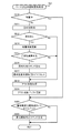
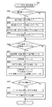
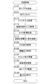
まず、周辺制御部電源投入時処理について、図59を参照して説明する。パチンコ機1に電源が投入されると、図17に示した周辺制御部1511の周辺制御MPU(図示省略)は、図59に示すように、周辺制御部電源投入時処理を行う。この周辺制御部電源投入時処理が開始されると、演出制御プログラムが周辺制御MPUの制御の下、初期設定処理を行う(ステップS1000)。この初期設定処理では、演出制御プログラムが、周辺制御MPU自身を初期化する処理と、ホットスタート/コールドスタートの判定処理と、リセット後のウェイトタイマを設定する処理等を行う。周辺制御MPUは、まず自身を初期化する処理を行うが、この周辺制御MPUを初期化する処理にかかる時間は、マイクロ秒(μs)オーダーであり、極めて短い時間で周辺制御MPUを初期化することができる。これにより、周辺制御MPUは、割り込み許可が設定された状態となることによって、例えば、後述する周辺制御部コマンド受信割り込み処理において、主制御基板1310から出力される、遊技演出の制御に関するコマンドやパチンコ機1の状態に関するコマンド等の各種コマンドを受信することができる状態となる。
[3-3b. Various control processes of peripheral control unit]
First, the peripheral control unit power-on process will be described with reference to FIG. When the
ステップS1000に続いて、演出制御プログラムは現在時刻情報取得処理を行う(ステップS1002)。この現在時刻情報取得処理では、RTC制御部から、年月日を特定するカレンダー情報と時分秒を特定する時刻情報とを取得して、周辺制御RAMに、現在のカレンダー情報としてカレンダー情報記憶部にセットするとともに、現在の時刻情報として時刻情報記憶部にセットする。 Subsequent to step S1000, the effect control program performs current time information acquisition processing (step S1002). In this current time information acquisition process, calendar information specifying the date and time and time information specifying hour, minute and second are acquired from the RTC control unit, and the calendar information storage unit as current calendar information is acquired in the peripheral control RAM. And set in the time information storage unit as the current time information.
ステップS1002に続いて、演出制御プログラムは、Vブランク信号検出フラグVB−FLGに値0をセットする(ステップS1006)。このVブランク信号検出フラグVB−FLGは、後述する周辺制御部定常処理を実行するか否かを決定するためのフラグであり、周辺制御部定常処理を実行するとき値1、周辺制御部定常処理を実行しないとき値0にそれぞれ設定される。Vブランク信号検出フラグVB−FLGは、周辺制御MPUからの画面データを受け入れることができる状態である旨を伝えるVブランク信号が入力されたことを契機として実行される後述する周辺制御部Vブランク信号割り込み処理において値1がセットされるようになっている。このステップS1006では、Vブランク信号検出フラグVB−FLGに値0をセットすることによりVブランク信号検出フラグVB−FLGを一度初期化している。
Subsequent to step S1002, the effect control program sets a
ステップS1006に続いて、演出制御プログラムは、Vブランク信号検出フラグVB−FLGが値1であるか否かを判定する(ステップS1008)。このVブランク信号検出フラグVB−FLGが値1でない(値0である)ときには、再びステップS1008に戻ってVブランク信号検出フラグVB−FLGが値1であるか否かを繰り返し判定する。このような判定を繰り返すことにより、周辺制御部定常処理を実行するまで待機する状態となる。 Subsequent to step S1006, the effect control program determines whether or not the V blank signal detection flag VB-FLG is 1 (step S1008). When the V blank signal detection flag VB-FLG is not 1 (value 0), the process returns to step S1008 again to repeatedly determine whether or not the V blank signal detection flag VB-FLG is 1. By repeating such a determination, the process waits until the peripheral control unit steady process is executed.
ステップS1008でVブランク信号検出フラグVB−FLGが値1であるとき、つまり周辺制御部定常処理を実行するときには、まず定常処理中フラグSP−FLGに値1をセットする(ステップS1009)。この定常処理中フラグSP−FLGは、周辺制御部定常処理を実行中であるとき値1、周辺制御部定常処理を実行完了したとき値0にそれぞれセットされる。
When the V blank signal detection flag VB-FLG has a value of 1 in step S1008, that is, when the peripheral control unit steady process is executed, a
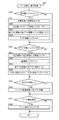
ステップS1009に続いて、演出制御プログラムは1ms割り込みタイマ起動処理を行う(ステップS1010)。この1ms割り込みタイマ起動処理では、後述する周辺制御部1msタイマ割り込み処理を実行するための1ms割り込みタイマを起動するとともに、この1ms割り込みタイマが起動して周辺制御部1msタイマ割り込み処理が実行された回数をカウントするための1msタイマ割り込み実行回数STNに値1をセットして1msタイマ割り込み実行回数STNの初期化も行う。この1msタイマ割り込み実行回数STNは周辺制御部1msタイマ割り込み処理で更新される。
Subsequent to step S1009, the effect control program performs 1 ms interrupt timer activation processing (step S1010). In this 1 ms interrupt timer starting process, a 1 ms interrupt timer for executing a later-described
ステップS1010に続いて、演出制御プログラムは、ランプデータ出力処理を行う(ステップS1012)。このランプデータ出力処理では、演出制御プログラムが図72に示したランプ駆動基板4170へのDMAシリアル連続送信を行う。ここでは、周辺制御MPUの周辺制御DMAコントローラを利用してランプ駆動基板用シリアルI/Oポート連続送信を行う。 Subsequent to step S1010, the effect control program performs lamp data output processing (step S1012). In this lamp data output process, the effect control program performs DMA serial continuous transmission to the lamp drive board 4170 shown in FIG. Here, the peripheral I / O port serial transmission is performed by using the peripheral control DMA controller of the peripheral control MPU.
ステップS1012に続いて、演出制御プログラムは、演出操作ユニット監視処理を行う(ステップS1014)。この演出操作ユニット監視処理では、後述する周辺制御部1msタイマ割り込み処理における演出操作ユニット情報取得処理において、演出操作ユニット220に設けられた各種検出スイッチ258からの検出信号に基づいて操作ボタン220Cの操作等を取得した各種情報に基づいて、操作ボタン220Cの操作有無を監視し、操作ボタン220Cの操作の状態を遊技演出に反映するか否かを適宜決定する。
Subsequent to step S1012, the effect control program performs effect operation unit monitoring processing (step S1014). In the effect operation unit monitoring process, the operation button 220C is operated based on detection signals from
ステップS1014に続いて、演出制御プログラムは、表示データ出力処理を行う(ステップS1016)。この表示データ出力処理では、後述する表示データ作成処理で音源内蔵VDPの内蔵VRAM上に生成した1画面分(1フレーム分)の描画データを音源内蔵VDPが遊技盤側装飾基板3053及び扉枠側装飾基板233に出力する。これにより、遊技盤側装飾基板3053及び扉枠側装飾基板233にさまざまな画面が描画される。
Subsequent to step S1014, the effect control program performs display data output processing (step S1016). In this display data output process, the drawing data for one screen (for one frame) generated on the built-in VRAM of the built-in sound source VDP by the display data creation process described later is displayed on the game board side
ステップS1016に続いて、演出制御プログラムは、音データ出力処理を行う(ステップS1018)。この音データ出力処理では、演出制御プログラムが、後述する音データ作成処理で音源内蔵VDPに設定された音楽及び効果音等の音データをスピーカ921に出力したり、音楽及び効果音のほかに報知音や告知音の音データをスピーカ921に出力したりする。
Subsequent to step S1016, the effect control program performs sound data output processing (step S1018). In this sound data output process, the production control program outputs the sound data such as music and sound effects set in the sound source built-in VDP in the sound data creation process described later to the
ステップS1018に続いて、演出制御プログラムはスケジューラ更新処理を行う(ステップS1020)。このスケジューラ更新処理では、演出制御プログラムが周辺制御RAMにセットされた各種スケジュールデータを更新する。例えば、スケジューラ更新処理では、画面生成用スケジュールデータを構成する時系列に配列された画面データのうち、先頭の画面データから何番目の画面データを音源内蔵VDPに出力するのかを指示するために、ポインタを更新する。 Subsequent to step S1018, the effect control program performs scheduler update processing (step S1020). In this scheduler update process, the effect control program updates various schedule data set in the peripheral control RAM. For example, in the scheduler update process, among the screen data arranged in time series constituting the screen generation schedule data, in order to instruct which screen data from the top screen data is output to the sound source built-in VDP, Update the pointer.
またスケジューラ更新処理では、発光態様生成用スケジュールデータを構成する時系列に配列された発光データのうち、先頭の発光データから何番目の発光データを各種LEDの発光態様とするのかを指示するために、ポインタを更新する。 Further, in the scheduler update process, in order to instruct the number of light emission data from the top light emission data to be used as the light emission modes of various LEDs among the light emission data arranged in time series constituting the light emission mode generation schedule data. , Update the pointer.
またスケジューラ更新処理では、音生成用スケジュールデータを構成する時系列に配列された、音楽や効果音等の音データ、報知音や告知音の音データを指示する音指令データのうち、先頭の音指令データから何番目の音指令データを音源内蔵VDPに出力するのかを指示するために、ポインタを更新する。 In addition, in the scheduler update process, the first sound among the sound data such as music and sound effects, and sound command data for instructing sound data of notification sounds and notification sounds arranged in time series constituting the sound generation schedule data. The pointer is updated to indicate what sound command data is output from the command data to the VDP with built-in sound source.
またスケジューラ更新処理では、電気的駆動源スケジュールデータを構成する時系列に配列されたモータやソレノイド等の電気的駆動源の駆動データのうち、先頭の駆動データから何番目の駆動データを出力対象とするのかを指示するために、ポインタを更新する。 In addition, in the scheduler update process, among the drive data of electric drive sources such as motors and solenoids arranged in time series constituting the electric drive source schedule data, the number of the drive data from the head drive data is output. The pointer is updated to indicate whether to do so.
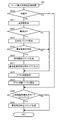
ステップS1020に続いて、演出制御プログラムは、受信コマンド解析処理を行う(ステップS1022)。この受信コマンド解析処理では、演出制御プログラムが、遊技盤側装飾基板3053から送信された情報や、主制御基板1310から送信された各種コマンドであって、後述する周辺制御部コマンド受信割り込み処理(コマンド受信手段)において受信した各種コマンドの解析を行う(コマンド解析手段)。
Subsequent to step S1020, the effect control program performs a received command analysis process (step S1022). In this received command analysis process, the effect control program is information transmitted from the game board side
ステップS1022に続いて、演出制御プログラムが警告処理を行う(ステップS1024)。この警告処理では、さらに、演出制御プログラムが、上述のようにステップS1022の受信コマンド解析処理で解析したコマンドに、所定の報知表示に区分される各種コマンドが含まれているときには、各種異常報知を実行するための異常表示態様に設定されている、画面生成用スケジュールデータ、発光態様生成用スケジュールデータ、音生成用スケジュールデータ、及び電気的駆動源スケジュールデータ等を、周辺制御部1511の周辺制御ROM又は周辺制御RAMから抽出して周辺制御RAMにセットする。なお、警告処理では、複数の異常が同時に発生した場合には、予め登録した優先度の高い順から異常報知から行われ、その異常が解決して残っている他の異常報知に自動的に遷移するようになっている。これにより、一の異常が発生した後であってその異常を解決する前に他の異常が発生して一の異常が発生しているという情報を失うことなく、複数の異常を同時に監視することができる。
Subsequent to step S1022, the effect control program performs warning processing (step S1024). In this warning process, when the command analyzed by the effect control program in the received command analysis process in step S1022 as described above includes various commands classified into predetermined notification displays, various abnormality notifications are issued. The peripheral control ROM of the
またさらに、この警告処理では、電源投入時から所定時間が経過した後に、演出制御プログラムが、上述した受信コマンド解析処理(ステップS1022)において解析したコマンドが、図90に示した状態表示に区分される各種コマンド、例えばエラー解除ナビコマンド(第2のエラー解除コマンド)である場合、演出動作に伴う通常の演出態様とは異なる態様に制御することにより、例えば、遊技盤側装飾基板3053(演出装置)、扉枠側装飾基板233(演出装置)、ランプ(演出装置)を用いて視覚的に外部に警告したり、スピーカを用いて聴覚的に外部に警告する(エラー報知手段)。このようにすると、悪意のある遊技者が、遊技状態であるにも拘わらず払出制御基板951の操作スイッチを操作することにより主制御基板1310にエラー解除ナビコマンドを入力しようと試行した際に、パチンコ機1が外部に警告を行う構成となっているため、遊技の進行に影響を及ぼしかねない主制御基板1310に対する不正行為が抑止されるようになる。
Furthermore, in this warning process, after a predetermined time has elapsed since the power was turned on, the command analyzed by the effect control program in the received command analysis process (step S1022) described above is classified into the status display shown in FIG. For example, an error canceling navigation command (second error canceling command), for example, a game board side decorative board 3053 (effect device) ), Visually warning the outside using the door frame side decorative board 233 (effect device) and lamp (effect device), or audibly warning the outside using a speaker (error notification means). In this way, when a malicious player tries to input an error release navigation command to the
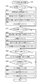
次に、上述したステップS1024に続いて、演出制御プログラムはRCT取得情報更新処理を行う(ステップS1026)。このRTC取得情報更新処理では、演出制御プログラムが、ステップS1002の現在時刻情報取得処理で取得して周辺制御RAMにセットした、カレンダー情報記憶部に記憶されたカレンダー情報と時刻情報記憶部に記憶された時刻情報とを更新する。このRCT取得情報更新処理により、時刻情報記憶部に記憶される時刻情報である時分秒が更新され、この更新される時刻情報に基づいてカレンダー情報記憶部に記憶されるカレンダー情報である年月日が更新される。 Next, following step S1024 described above, the effect control program performs an RCT acquisition information update process (step S1026). In this RTC acquisition information update process, the effect control program is stored in the calendar information and time information storage unit acquired in the current time information acquisition process in step S1002 and set in the peripheral control RAM and stored in the calendar information storage unit. Update the time information. By this RCT acquisition information update process, the hour, minute and second as time information stored in the time information storage unit are updated, and the year and month as calendar information stored in the calendar information storage unit based on the updated time information. The day is updated.
ステップS1026に続いて、演出制御プログラムはランプデータ作成処理を行う(ステップS1028)。このランプデータ作成処理では、この演出制御プログラムが、ステップS1020のスケジューラ更新処理においてポインタが更新されて、発光態様生成用スケジュールデータを構成する時系列に配列された発光データのうち、そのポインタが指示する発光データに基づいて、遊技盤5に設けた各種装飾基板の複数のLEDへの点灯信号、点滅信号、又は階調点灯信号を出力するための遊技盤側発光データSL−DATを、周辺制御部1511の周辺制御ROM又は周辺制御RAMから抽出して作成するとともに、周辺制御RAMにセットするとともに、扉枠3に設けた各種装飾基板の複数のLEDへの点灯信号、点滅信号又は階調点灯信号を出力するための扉側発光データSTL−DATを、周辺制御部1511の周辺制御ROM又は周辺制御RAMから抽出して作成して、周辺制御RAMにセットする。
Subsequent to step S1026, the effect control program performs lamp data creation processing (step S1028). In this lamp data creation process, the effect control program updates the pointer in the scheduler update process in step S1020, and the pointer indicates the light emission data arranged in time series constituting the light emission mode generation schedule data. Peripheral control of the game board side light emission data SL-DAT for outputting a lighting signal, a blinking signal, or a gradation lighting signal to a plurality of LEDs of various decorative boards provided on the
ステップS1028に続いて、演出制御プログラムは表示データ作成処理を行う(ステップS1030)。この表示データ作成処理では、演出制御プログラムが、ステップS1020のスケジューラ更新処理においてポインタが更新されて、画面生成用スケジュールデータを構成する時系列に配列された画面データのうち、そのポインタが示す画面データを、周辺制御部1511の周辺制御ROM又は周辺制御RAMから抽出して音源内蔵VDPに出力する。音源内蔵VDPは、周辺制御MPUから画面データが入力されると、この入力された画面データに基づいて液晶及び音制御ROM1512bからキャラクタデータを抽出してスプライトデータを作成して遊技盤側装飾基板3053及び扉枠側装飾基板233に表示する1画面分(1フレーム分)の描画データを内蔵VRAM上に生成する。
Subsequent to step S1028, the effect control program performs display data creation processing (step S1030). In this display data creation process, the presentation control program updates the pointer in the scheduler update process in step S1020, and the screen data indicated by the pointer among the screen data arranged in time series constituting the schedule data for screen generation. Are extracted from the peripheral control ROM or peripheral control RAM of the
ステップS1030に続いて、演出制御プログラムは音データ作成処理を行う(ステップS1032)。この音データ作成処理では、演出制御プログラムが、ステップS1020のスケジューラ更新処理においてポインタが更新されて、音生成用スケジュールデータを構成する時系列に配列された音指令データのうち、そのポインタが指示する音指令データを、周辺制御部1511の周辺制御ROM又は周辺制御RAMから抽出して音源内蔵VDPに出力する。音源内蔵VDPは、周辺制御MPUから音指令データが入力されると、液晶及び音制御ROMに記憶されている音楽や効果音等の音データを抽出して内蔵音源を制御することにより、音指令データに規定された、トラック番号に従って音楽及び効果音等の音データを組み込むとともに、出力チャンネル番号に従って使用する出力チャンネルを設定する。
Subsequent to step S1030, the effect control program performs sound data creation processing (step S1032). In the sound data creation process, the effect control program updates the pointer in the scheduler update process in step S1020, and the pointer indicates the sound command data arranged in time series constituting the sound generation schedule data. The sound command data is extracted from the peripheral control ROM or peripheral control RAM of the
ステップS1032に続いて、演出制御プログラムはバックアップ処理を行う(ステップS1034)。このバックアップ処理では、演出制御プログラムが、周辺制御MPUと外付けされる周辺制御RAMに記憶されている内容を、バックアップ第1エリアと、バックアップ第2エリアと、にそれぞれコピーしてバックアップするとともに、周辺制御MPUと外付けされる周辺制御SRAMに記憶されている内容を、バックアップ第1エリアと、バックアップ第2エリアと、にそれぞれコピーしてバックアップする。 Subsequent to step S1032, the effect control program performs a backup process (step S1034). In this backup process, the production control program copies and backs up the contents stored in the peripheral control MPU and the peripheral control RAM externally attached to the backup first area and the backup second area, The contents stored in the peripheral control SRAM externally attached to the peripheral control MPU are copied and backed up in the backup first area and the backup second area, respectively.
ステップS1034に続いて、WDTクリア処理を行う(ステップS1036)。このWDTクリア処理では、周辺制御内蔵WDT1511afと、周辺制御外部WDT1511eと、にクリア信号を出力して周辺制御MPUにリセットがかからないようにしている。 Subsequent to step S1034, WDT clear processing is performed (step S1036). In this WDT clear process, a clear signal is output to the peripheral control built-in WDT 1511af and the peripheral control external WDT 1511e so that the peripheral control MPU is not reset.
ステップS1036に続いて、演出制御プログラムが、周辺制御部定常処理の実行完了として定常処理中フラグSP−FLGに値0をセットし(ステップS1038)、再びステップS1006に戻り、Vブランク信号検出フラグVB−FLGに値0をセットして初期化し、後述する周辺制御部Vブランク信号割り込み処理においてVブランク信号検出フラグVB−FLGに値1がセットされるまで、ステップS1008の判定を繰り返し行う。つまりステップS1008では、Vブランク信号検出フラグVB−FLGに値1がセットされるまで待機し、ステップS1008でVブランク信号検出フラグVB−FLGが値1であると判定されると、ステップS1009〜ステップS1038の処理を行い、再びステップS1006に戻る。このように、ステップS1008でVブランク信号検出フラグVB−FLGが値1であると判定されると、ステップS1009〜ステップS1038の処理を行うようになっている。ステップS1009〜ステップS1038の処理を「周辺制御部定常処理」という。
Subsequent to step S1036, the effect control program sets the
この周辺制御部定常処理は、演出制御プログラムが、まずステップS1009で周辺制御部定常処理を実行中であるとして定常処理中フラグSP−FLGに値1をセットすることから開始し、ステップS1010で1ms割り込みタイマ起動処理を行い、ステップS1012、ステップS1014、・・・、そしてステップS1036の各処理を行って最後にステップS1038において周辺制御部定常処理の実行完了として定常処理中フラグSP−FLGに値0をセットすると、完了することとなる。周辺制御部定常処理は、ステップS1008でVブランク信号検出フラグVB−FLGが値1であるときに実行される。このVブランク信号検出フラグVB−FLGは、上述したように、周辺制御MPUからの画面データを受け入れることができる状態である旨を伝えるVブランク信号が音源内蔵VDPから入力されたことを契機として実行される後述する周辺制御部Vブランク信号割り込み処理において値1がセットされるようになっている。本実施形態では、遊技盤側装飾基板3053及び扉枠側装飾基板233のフレーム周波数(1秒間あたりの画面更新回数)として、上述したように、概ね秒間30fpsに設定しているため、Vブランク信号が入力される間隔は、約33.3ms(=1000ms÷30fps)となっている。つまり、周辺制御部定常処理は、約33.3msごとに繰り返し実行されるようになっている。
The peripheral control unit steady process starts from the fact that the effect control program first sets the
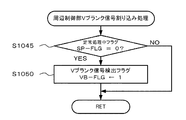
次に、図60に示した、周辺制御部1511の周辺制御MPUからの画面データを受け入れることができる状態である旨を伝えるVブランク信号が液晶表示制御部1512の音源内蔵VDPから入力されたことを契機として実行する周辺制御部Vブランク信号割り込み処理について説明する。この周辺制御部Vブランク信号割り込み処理が開始されると、周辺制御部1511の周辺制御MPUは、図60に示すように、定常処理中フラグSP−FLGが値0であるかを判定する(ステップS1045)。この定常処理中フラグSP−FLGは、上述したように、図59の周辺制御部電源投入時処理におけるステップS1009〜ステップS1038の周辺制御部定常処理を実行中であるとき値1、周辺制御部定常処理を実行完了したとき値0にそれぞれセットされる。
Next, the V blank signal indicating that the screen data from the peripheral control MPU of the
ステップS1045で定常処理中フラグSP−FLGが値0でない(値1である)とき、つまり周辺制御部定常処理を実行中であるときには、そのままこのルーチンを終了する。一方、ステップS1045で定常処理中フラグSP−FLGが値0であるとき、つまり周辺制御部定常処理を実行完了したときには、Vブランク信号検出フラグVB−FLGに値1をセットし(ステップS1050)、このルーチンを終了する。このVブランク信号検出フラグVB−FLGは、上述したように、周辺制御部定常処理を実行するか否かを決定するためのフラグであり、周辺制御部定常処理を実行するとき値1、周辺制御部定常処理を実行しないとき値0にそれぞれ設定される。
If the steady process flag SP-FLG is not 0 (value 1) in step S1045, that is, if the peripheral control unit steady process is being executed, this routine is terminated. On the other hand, when the steady processing flag SP-FLG is 0 in step S1045, that is, when the execution of the peripheral control unit steady processing is completed, the
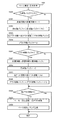
次に、図59の周辺制御部電源投入時処理の周辺制御部定常処理におけるステップS1010で1ms割り込みタイマの起動により1ms割り込みタイマが発生するごとに繰り返し実行する周辺制御部1msタイマ割り込み処理について説明する。この周辺制御部1msタイマ割り込み処理が開始されると、周辺制御部1511の周辺制御MPUは、図61に示すように、1msタイマ割り込み実行回数STNが33回より小さいか否かを判定する(ステップS1100)。この1msタイマ割り込み実行回数STNは、上述したように、図59の周辺制御部電源投入時処理の周辺制御部定常処理におけるステップS1010の1ms割り込みタイマ起動処理で1ms割り込みタイマが起動して本ルーチンである周辺制御部1msタイマ割り込み処理が実行された回数をカウントするカウンタである。本実施形態では、遊技盤側装飾基板3053及び扉枠側装飾基板233のフレーム周波数(1秒間あたりの画面更新回数)として、上述したように、概ね秒間30fpsに設定しているため、Vブランク信号が入力される間隔は、約33.3ms(=1000ms÷30fps)となっている。つまり、周辺制御部定常処理は、約33.3msごとに繰り返し実行されるようになっているため、周辺制御部定常処理におけるステップS1010で1ms割り込みタイマを起動した後、次の周辺制御部定常処理が実行されるまでに、周辺制御部1msタイマ割り込み処理が32回だけ実行されるようになっている。具体的には、周辺制御部定常処理におけるステップS1010で1ms割り込みタイマが起動されると、まず1回目の1msタイマ割り込みが発生し、2回目、・・・、そして32回目の1msタイマ割り込みが順次発生することとなる。
Next, the
ステップS1100で1msタイマ割り込み実行回数STNが33回より小さくないとき、つまり33回目の1msタイマ割り込みが発生してこの周辺制御部1msタイマ割り込み処理が開始されたときには、そのままこのルーチンを終了する。33回目の1msタイマ割り込みの発生が次回のVブランク信号の発生よりたまたま先行した場合には、本実施形態では、割り込み処理の優先順位として、周辺制御部1msタイマ割り込み処理の方が周辺制御部Vブランク割り込み処理と比べて高く設定されているものの、この33回目の1msタイマ割り込みによる周辺制御部1msタイマ割り込み処理の開始を強制的にキャンセルするようになっている。換言すると、本実施形態では、Vブランク信号が周辺制御基板1510のシステム全体を支配する信号であるため、33回目の1msタイマ割り込みの発生が次回のVブランク信号の発生よりたまたま先行した場合には、周辺制御部Vブランク割り込み処理を実行するために33回目の1msタイマ割り込みによる周辺制御部1msタイマ割り込み処理の開始が強制的にキャンセルさせられている。そして、Vブランク信号の発生により周辺制御部定常処理におけるステップS1010で1ms割り込みタイマを再び起動した後、新たに1回目の1msタイマ割り込みの発生による周辺制御部1msタイマ割り込み処理を開始するようになっている。
When the number of 1 ms timer interrupt executions STN is not smaller than 33 in step S1100, that is, when the 33rd 1 ms timer interrupt is generated and the
一方、ステップS1100で1msタイマ割り込み実行回数STNが33回より小さいときには、1msタイマ割り込み実行回数STNに値1だけ足す(インクリメントする、ステップS1102)。この1msタイマ割り込み実行回数STNに値1が足されることにより、図59の周辺制御部電源投入時処理の周辺制御部定常処理におけるステップS1010の1ms割り込みタイマ起動処理で1ms割り込みタイマが起動して本ルーチンである周辺制御部1msタイマ割り込み処理が実行された回数が1回分だけ増えることとなる。
On the other hand, when the 1 ms timer interrupt execution count STN is smaller than 33 in step S1100, the
ステップS1102に続いて、モータ及びソレノイド駆動処理を行う(ステップS1104)。このモータ及びソレノイド駆動処理では、周辺制御MPUと周辺制御RAMにセットされた電気的駆動源スケジュールデータを構成する時系列に配列されたモータやソレノイド等の電気的駆動源の駆動データのうち、ポインタが指示する駆動データに従って、各種モータやソレノイド等の電気的駆動源を駆動するとともに、時系列に規定された次の駆動データにポインタを更新し、このモータ及びソレノイド駆動処理を実行するごとに、ポインタを更新する。 Subsequent to step S1102, motor and solenoid drive processing is performed (step S1104). In this motor and solenoid drive processing, pointers out of drive data of electric drive sources such as motors and solenoids arranged in time series constituting the electric drive source schedule data set in the peripheral control MPU and the peripheral control RAM. In accordance with the drive data instructed by the motor, an electric drive source such as various motors and solenoids is driven, the pointer is updated to the next drive data defined in time series, and each time this motor and solenoid drive process is executed, Update the pointer.
ステップS1104に続いて、可動体情報取得処理を行う(ステップS1106)。この可動体情報取得処理では、遊技盤5に設けた各種検出スイッチからの検出信号が入力されているか否かを判定することにより各種検出スイッチからの検出信号の履歴情報(例えば、原位置履歴情報、可動位置履歴情報など。)を作成し、周辺制御RAMにセットする。この周辺制御RAMにセットされる各種検出スイッチからの検出信号の履歴情報から遊技盤5に設けた各種可動体の原位置や可動位置等を取得することができる。
Following step S1104, movable body information acquisition processing is performed (step S1106). In this movable body information acquisition process, it is determined whether or not detection signals from various detection switches provided in the
ステップS1106に続いて、演出操作ユニット情報取得処理を行う(ステップS1108)。この演出操作ユニット情報取得処理では、演出操作ユニット220に設けられた各種検出スイッチからの検出信号が入力されているか否かを判定することにより各種検出スイッチからの検出信号の履歴情報(例えば、操作ボタン220Cの操作履歴情報など)を作成し、周辺制御RAMにセットする。この周辺制御RAMにセットされる各種検出スイッチからの検出信号の履歴情報から操作ボタン220Cの操作有無を取得することができる。
Subsequent to step S1106, an effect operation unit information acquisition process is performed (step S1108). In this effect operation unit information acquisition process, it is determined whether or not detection signals from various detection switches provided in the
ステップS1108に続いて、描画状態情報取得処理を行う(ステップS1110)。この描画状態情報取得処理では、扉枠側装飾基板233の扉枠側演出用レシーバICから出力されるLOCKN信号の履歴情報を作成し、周辺制御RAMにセットする。LOCKN信号は、前述したように、扉枠側装飾基板233の扉枠側演出用レシーバICSDIC0が、周辺制御基板1510に備える扉枠側演出用トランスミッタIC1512dから受信した描画データが異常なデータであると判断すると、その旨を伝えるために出力する信号である。
Following step S1108, drawing state information acquisition processing is performed (step S1110). In this drawing state information acquisition process, history information of the LOCKN signal output from the door frame side effect receiver IC of the door frame side
ステップS1110に続いて、バックアップ処理を行い(ステップS1112)、このルーチンを終了する。このバックアップ処理では、周辺制御RAMに記憶されている内容を、バックアップ第1エリアと、バックアップ第2エリアと、にそれぞれコピーしてバックアップするとともに、周辺制御SRAMに記憶されている内容を、バックアップ第1エリアと、バックアップ第2エリアと、にそれぞれコピーしてバックアップする。 Subsequent to step S1110, backup processing is performed (step S1112), and this routine is terminated. In this backup process, the contents stored in the peripheral control RAM are copied and backed up to the backup first area and the backup second area, respectively, and the contents stored in the peripheral control SRAM are backed up. Copy to 1 area and backup 2nd area to backup.
このように、周辺制御部1msタイマ割り込み処理では、1msという期間内において、演出の進行として上述したステップS1104〜ステップS1108の演出に関する各種処理を実行している。これに対して、図59の周辺制御部電源投入時処理における周辺制御部定常処理では、約33.3msという期間内において、演出の進行として上述したステップS1012〜ステップS1032の演出に関する各種処理を実行している。周辺制御部1msタイマ割り込み処理では、ステップS1100で1msタイマ割り込み実行回数STNが値33より小さくないとき、つまり33回目の1msタイマ割り込みが発生してこの周辺制御部1msタイマ割り込み処理が開始されたときには、そのままこのルーチンを終了するようになっているため、仮に、33回目の1msタイマ割り込みの発生が次回のVブランク信号の発生よりたまたま先行した場合でも、この33回目の1msタイマ割り込みによる周辺制御部1msタイマ割り込み処理の開始を強制的にキャンセルし、Vブランク信号の発生により周辺制御部定常処理におけるステップS1010で1ms割り込みタイマを再び起動した後、新たに1回目の1msタイマ割り込みの発生による周辺制御部1msタイマ割り込み処理を開始するようになっている。つまり、周辺制御部定常処理による演出の進行状態とタイマ割り込み制御である周辺制御部1msタイマ割り込み処理による演出の進行状態との整合性が崩れないようになっている。したがって、演出の進行状態を確実に整合させることができる。
As described above, in the
また、上述したように、Vブランク信号が出力される間隔は、遊技盤側装飾基板3053及び扉枠側装飾基板233の液晶サイズによって多少変化するし、周辺制御MPUと音源内蔵VDPとが実装された周辺制御基板1510の製造ロットにおいてもVブランク信号が出力される間隔が多少変化する場合もある。本実施形態では、Vブランク信号が周辺制御基板1510のシステム全体を支配する信号であるため、33回目の1msタイマ割り込みの発生が次回のVブランク信号の発生よりたまたま先行した場合には、周辺制御部Vブランク割り込み処理を実行するために33回目の1msタイマ割り込みによる周辺制御部1msタイマ割り込み処理の開始が強制的にキャンセルさせられている。つまり本実施形態では、Vブランク信号が出力される間隔が多少変化する場合であっても、33回目の1msタイマ割り込みによる周辺制御部1msタイマ割り込み処理の開始を強制的にキャンセルすることによって、このVブランク信号が出力される間隔が多少変化することによる時間ズレを吸収することができるようになっている。
In addition, as described above, the interval at which the V blank signal is output varies slightly depending on the liquid crystal sizes of the game board side
[3−4.液晶表示制御部]
次に、周辺制御基板1510におけるメイン液晶表示装置1600、サブ液晶表示装置3114や上皿液晶表示装置244の描画制御を行う液晶表示制御部1512は、詳細な図示は省略するが、マイクロプロセッサとしての表示制御MPUと、各種処理プログラム、各種コマンド及び各種データを記憶する表示制御ROMと、メイン液晶表示装置1600や上皿液晶表示装置244を表示制御するVDP(Video Display Processorの略)と、メイン液晶表示装置1600、サブ液晶表示装置3114や上皿液晶表示装置244に表示される画面の各種データを記憶する画像ROMと、この画像ROMに記憶されている各種データが転送されてコピーされる画像RAMと、を備えている。
[3-4. Liquid crystal display controller]
Next, a liquid crystal
この表示制御MPUは、パラレルI/Oポート、シリアルI/Oポート等を内蔵しており、周辺制御部1511からの制御データ(表示コマンド)に基づいてVDPを制御してメイン液晶表示装置1600、サブ液晶表示装置3114や上皿液晶表示装置244の描画制御を行っている。なお、表示制御MPUは、正常に動作していると、その旨を伝える動作信号を周辺制御部1511に出力する。また表示制御MPUは、VDPから実行中信号が入力されており、この実行中信号の出力が16msごとに停止されたことを契機として、割り込み処理を行っている。
The display control MPU includes a parallel I / O port, a serial I / O port, and the like, and controls the VDP based on control data (display command) from the
表示制御ROMは、メイン液晶表示装置1600、サブ液晶表示装置3114や上皿液晶表示装置244に描画する画面を生成するための各種プログラムのほかに、周辺制御部1511からの制御データ(表示コマンド)と対応するスケジュールデータ、その制御データ(表示コマンド)と対応する非常駐領域転送スケジュールデータ等を複数記憶している。スケジュールデータは、画面の構成を規定する画面データが時系列に配列されて構成されており、メイン液晶表示装置1600、サブ液晶表示装置3114や上皿液晶表示装置244に描画する画面の順序が規定されている。非常駐領域転送スケジュールデータは、画像ROMに記憶されている各種データを画像RAMの非常駐領域に転送する際に、その順序を規定する非常駐領域転送データが時系列に配列されて構成されている。この非常駐領域転送データは、スケジュールデータの進行に従ってメイン液晶表示装置1600、サブ液晶表示装置3114や上皿液晶表示装置244に描画される画面データを、前もって、画像ROMから画像RAMの非常駐領域に各種データを転送する順序が規定されている。
The display control ROM includes control programs (display commands) from the
表示制御MPUは、周辺制御部1511からの制御データ(表示コマンド)と対応するスケジュールデータの先頭の画面データを表示制御ROMから抽出してVDPに出力した後に、先頭の画面データに続く画面データを表示制御ROMから抽出してVDPに出力する。このように、表示制御MPUは、スケジュールデータに時系列に配列された画面データを、先頭の画面データから1つずつ表示制御ROMから抽出してVDPに出力する。
The display control MPU extracts the first screen data of the schedule data corresponding to the control data (display command) from the
VDPは、表示制御MPUから出力された画面データが入力されると、この入力された画面データに基づいて画像RAMからスプライトデータを抽出してメイン液晶表示装置1600、サブ液晶表示装置3114や上皿液晶表示装置244に表示する描画データを生成し、この生成した描画データを、メイン液晶表示装置1600、サブ液晶表示装置3114や上皿液晶表示装置244に出力する。またVDPは、メイン液晶表示装置1600、サブ液晶表示装置3114や上皿液晶表示装置244が、表示制御MPUからの画面データを受入れないときに、その旨を伝える実行中信号を表示制御MPUに出力する。なお、VDPは、ラインバッファ方式が採用されている。この「ラインバッファ方式」とは、メイン液晶表示装置1600、サブ液晶表示装置3114や上皿液晶表示装置244の左右方向を描画する1ライン分の描画データをラインバッファに保持し、このラインバッファに保持した1ライン分の描画データを、メイン液晶表示装置1600、サブ液晶表示装置3114や上皿液晶表示装置244に出力する方式である。
When the screen data output from the display control MPU is input to the VDP, the sprite data is extracted from the image RAM based on the input screen data, and the main liquid
画像ROMには、極めて多くのスプライトデータが記憶されており、その容量が大きくなっている。画像ROMの容量が大きくなると、つまり、メイン液晶表示装置1600、サブ液晶表示装置3114や上皿液晶表示装置244に描画するスプライトの数が多くなると、画像ROMのアクセス速度が無視できなくなり、メイン液晶表示装置1600、サブ液晶表示装置3114や上皿液晶表示装置244に描画する速度に影響することとなる。そこで、本実施形態では、アクセス速度の速い画像RAMに、画像ROMに記憶されているスプライトデータを転送してコピーし、この画像RAMからスプライトデータを抽出している。なお、スプライトデータは、スプライトをビットマップ形式に展開する前のデータである基データであり、圧縮された状態で画像ROMに記憶されている。
The image ROM stores an extremely large amount of sprite data and has a large capacity. When the capacity of the image ROM increases, that is, when the number of sprites drawn on the main liquid
ここで、「スプライト」について説明すると、「スプライト」とは、メイン液晶表示装置1600や上皿液晶表示装置244に、纏まった単位として表示されるイメージである。例えば、メイン液晶表示装置1600、サブ液晶表示装置3114や上皿液晶表示装置244に、種々の人物(キャラクタ)を表示させる場合には、夫々の人物を描くためのデータを「スプライト」と呼ぶ。これにより、メイン液晶表示装置1600、サブ液晶表示装置3114や上皿液晶表示装置244に複数人の人物を表示させる場合には、複数のスプライトを用いることとなる。また人物のほかに、背景を構成する家、山、道路等もスプライトであり、背景全体を1つのスプライトとすることもできる。これらのスプライトは、画面に配置される位置やスプライト同士が重なる場合の上下関係(以下、「スプライトの重ね合わせの順序」と記載する。)が設定されてメイン液晶表示装置1600、サブ液晶表示装置3114や上皿液晶表示装置244に描画される。
Here, the “sprite” will be described. The “sprite” is an image displayed as a unit on the main liquid
なお、スプライトは縦横それぞれ64画素の矩形領域を複数張り合わせて構成されている。この矩形領域を描くためのデータを「スプライトキャラクタ」と呼ぶ。小さなスプライトの場合には1つのスプライトキャラクタを用いて表現することができるし、人物など比較的大きいスプライトの場合には、例えば横2×縦3などで配置した合計6個のスプライトキャラクタを用いて表現することができる。背景のように更に大きいスプライトの場合には更に多数のスプライトキャラクタを用いて表現することができる。このように、スプライトキャラクタの数及び配置は、スプライトごとに任意に指定することができるようになっている。 Note that the sprite is configured by bonding a plurality of rectangular regions of 64 pixels vertically and horizontally. Data for drawing this rectangular area is called a “sprite character”. In the case of a small sprite, it can be expressed by using one sprite character, and in the case of a relatively large sprite such as a person, for example, a total of 6 sprite characters arranged in horizontal 2 × vertical 3 etc. are used. Can be expressed. In the case of a larger sprite such as the background, it can be expressed using a larger number of sprite characters. Thus, the number and arrangement of sprite characters can be arbitrarily designated for each sprite.
メイン液晶表示装置1600、サブ液晶表示装置3114や上皿液晶表示装置244は、その正面から見て左から右に向かって順次、画素に沿った一方向に画素ごとの表示状態を設定する主走査と、その一方向と交差する方向に主走査を繰り返し行う副走査と、によって駆動される。メイン液晶表示装置1600、サブ液晶表示装置3114や上皿液晶表示装置244は、液晶表示制御部1512から出力された1ライン分の描画データが入力されると、主走査としてメイン液晶表示装置1600、サブ液晶表示装置3114や上皿液晶表示装置244の正面から見て左から右に向かって順次、1ライン分の画素にそれぞれ出力する。そして1ライン分の出力が完了すると、メイン液晶表示装置1600、サブ液晶表示装置3114や上皿液晶表示装置244は、副走査として直下のラインに移行し、同様に次ライン分の描画データが入力されると、この次ライン分の描画データに基づいて主走査としてメイン液晶表示装置1600、サブ液晶表示装置3114や上皿液晶表示装置244の正面から見て左から右に向かって順次、1ライン分の画素にそれぞれ出力する。
The main liquid
[4.遊技内容]
次に、本実施形態のパチンコ機1による遊技内容について、主に図10、図16及び図17等を参照して説明する。本実施形態のパチンコ機1は、扉枠3の前面右下隅に配置されたハンドルユニット500のハンドルレバー504を遊技者が回転操作することで、皿ユニット200の上皿201に貯留された遊技球が、遊技盤5における外レール1001と内レール1002との間を通って遊技領域5a内の上部へと打ち込まれて、遊技球による遊技が開始される。遊技領域5a内の上部へ打ち込まれた遊技球は、その打込強さによってセンター役物2500の左側、或いは、右側の何れかを流下する。なお、遊技球の打込み強さは、ハンドルレバー504の回転量によって調整することができ、時計回りの方向へ回転させるほど強く打込むことができ、連続で一分間に最大100個の遊技球、つまり、0.6秒間隔で遊技球を打込むことができる。
[4. Game contents]
Next, game contents by the
また、遊技領域5a内には、適宜位置に所定のゲージ配列で複数の障害釘(図示は省略)が遊技パネル1100(パネル板1110)の前面に植設されており、遊技球が障害釘に当接することで、遊技球の流下速度が抑制されると共に、遊技球に様々な動きが付与されて、その動きを楽しませられるようになっている。また、遊技領域5a内には、障害釘の他に、遊技球の当接により回転する風車(図示は省略)が適宜位置に備えられている。
In the
センター役物2500の上部へ打込まれた遊技球は、センター役物2500の前周壁部2512の外周面のうち、最も高くなった部位よりも正面視左側へ進入すると、図示しない複数の障害釘に当接しながら、センター役物2500よりも左側の領域を流下することとなる。そして、センター役物2500の左側の領域を流下する遊技球が、センター役物2500の前周壁部2512の外周面に開口しているワープ入口2520に進入すると、ワープ通路2521を通ってセンター役物2500の枠内に開口しているワープ出口2522から誘導路2523を通ってステージ2530に供給される。
When a game ball that has been thrown into the upper portion of the
ワープ出口2522からステージ2530に供給された遊技球は、ステージ2530上を転動して左右に行ったり来たりして、左右方向中央の中央誘導部2531、又は、その左右にあるサイド誘導部2532の何れかから後方に放出される。ステージ2530の中央誘導部2531から遊技球が遊技領域5a内に放出されと、この中央誘導部2531が第一始動口2002の直上に位置していることから、中央誘導部2531から放出された遊技球は、高い確率で第一始動口2002に受入れられる。この第一始動口2002に遊技球が受入れられると、主制御基板1310及び払出制御基板951を介して払出装置830から所定数(例えば、3個)の遊技球が、上皿201に払出される。
The game ball supplied from the
ステージ2530を転動している遊技球が、サイド誘導部2532から遊技領域5a内に放出されと、始動口ユニット2100へ向かって流下する。センター役物2500のステージ2530から遊技領域5a内に放出された遊技球は、始動口ユニット2100の第一始動口2002や、開状態の第一大入賞口2005等に受入れられる可能性がある。
When the game ball rolling on the
ところで、センター役物2500の左側へ流下した遊技球が、ワープ入口2520に進入しなかった場合、サイドユニット上2300の棚部2302により左右方向中央側へ寄せられ、サイドユニット下2200の一般入賞口2001や第一始動口2002等に受入れられる可能性がある。そして、一般入賞口2001に遊技球が受入れられると、主制御基板1310及び払出制御基板951を介して払出装置830から所定数(例えば、10個)の遊技球が、上皿201に払出される。
By the way, when the game ball that has flowed down to the left side of the
一方、遊技領域5a内においてセンター役物2500の上部に打込まれた遊技球が、センター役物2500の前周壁部2512の外周面の最も高くなった部位よりも右側に進入する(打込まれる)と、右打遊技領域2540の右上流通空間2541内に進入する。この右上流通空間2541内には、図示は省略するが、複数の障害釘が植設されており、遊技球が障害釘に当接してその流下方向を様々に変化させながら流通する。この右上流通空間3541内には、上部にゲート部2003が、下部に一般入賞口2001と通常は第二始動口扉部材2549により閉鎖されている第二始動口2004が備えられている。
On the other hand, in the
右上流通空間2541内を流下した遊技球は、その下流側の右流通路2542を通って右下流通空間2543内に進入する。この右下流通空間2543に進入した遊技球は、第二大入賞口2006として左右に並んだ第二上大入賞口2006aと第二下大入賞口2006bを閉鎖している第二上大入賞口扉部材2552と第二下大入賞口扉部材2555の上面が底面を形成している第二アタッカ通路2543aを通り、低くなっている正面視左側の放出板部2559の左端から遊技領域5a内に放出される。第二アタッカ通路2543aの下流端(放出板部2559)は、始動口ユニット2100の第一大入賞口2005へ遊技球が向かうように開口しており、第一大入賞口2005が開状態の時に、第二アタッカ通路2543aから遊技領域5a内に遊技球が放出されると、高い確率で遊技球が第一大入賞口2005に受入れられる。
The game ball that has flowed down in the upper
この右流通路2542及び右下流通空間2543を流通する遊技球は、複数の減速リブ2546により、流通速度の増加が抑制されながら流下する。なお、ごくまれに、右下流通空間2543内において、第二アタッカ通路2543aの上流端付近で分岐している排出通路2543bに進入することがあり、排出通路2543bに進入した遊技球は遊技領域5a内に戻されることなく第二アウト口2543cから遊技盤5外に排出される。
The game balls flowing through the right flow path 2542 and the lower
右打して右上流通空間2541内に進入した遊技球が、ゲート部2003を通過してゲートセンサ2547により検知されると、主制御基板1310において予め決められている数値範囲で更新される普通乱数の中から一の普通乱数を取得し、この取得した普通乱数を予め決められた普通当り判定テーブルと照合することで普通抽選を行う。後述する時短制御を実行していない場合にこの普通抽選の結果が「普通当り」となると第二始動口扉部材2549が1回だけ正面視反時計回りの方向に回動して第二始動口2004を開状態とし、所定時間(この例では0.5秒)の間に亘り第二始動口2004への遊技球の受入れが可能となる。一方、時短制御を実行している場合には普通抽選にて「普通当り」として「第一普通当り」、「第二普通当り」、「第三普通当り」のいずれとなったかを抽選する。そして、時短制御を実行している場合に普通抽選の普通抽選結果が「第一普通当り」、「第二普通当り」、「第三普通当り」のいずれかとなると第二始動口扉部材2549が正面視反時計回りの方向へ回動して第二始動口2004を開状態とすることで所定期間に亘って第二始動口2004への遊技球の受入れが可能な状態とした後、正面視反時計回りの方向へ回動して第二始動口2004を閉状態とすることで第二始動口2004への遊技球の受入れが不可能な状態にする開閉制御を所定回数(この例では5回)に亘って繰り返す。なお、普通抽選の普通抽選結果が「第一普通当り」となった場合には第二始動口2004が遊技球の受入れを可能な状態とされる5回夫々の期間として「0.3秒」、「0.28秒」、「0.3秒」、「0.28秒」、「0.3秒」とされ、普通抽選の普通抽選結果が「第二普通当り」となった場合には第二始動口2004が遊技球の受入れを可能な状態とされる5回夫々の期間として「0.3秒」、「0.28秒」、「1.1秒」、「0.28秒」、「0.3秒」とされ、普通抽選の普通抽選結果が「第三普通当り」となった場合には第二始動口2004が遊技球の受入れを可能な状態とされる5回夫々の期間として「0.3秒」、「0.28秒」、「0.3秒」、「0.28秒」、「1.1秒」とされ、「第二普通当り」及び「第三普通当り」では「第一普通当り」よりも遊技者に有利(第二始動口2004への遊技球の受入れが容易)な当りとなっている。また、第二始動口2004に遊技球が受入れられると、主制御基板1310及び払出制御基板951を介して払出装置830から所定数(例えば、3個)の遊技球が、上皿201に払出される。
When a game ball that hits the right and enters the upper
本実施形態では、ゲート部2003を遊技球が通過したことに基づいて機能表示ユニット1400の普通図柄表示器で行われる普通図柄の変動表示において、普通図柄の変動表示を開始してから普通図柄を停止表示するまで(普通抽選結果を示唆するまで)にある程度の時間を設定している(例えば、0.01〜60秒、普通変動時間とも称す)。第二始動口2004では、普通変動時間の経過後に第二始動口扉部材2549が回動して開状態となる。なお、後述する時短制御の実行中には通常(時短制御を実行していない状態)よりも普通変動時間を短縮させる制御を実行するようになっている。また、第二始動口扉部材2549を回動して第二始動口2004を開状態とする開放時間については、遊技状態に応じて変化させるようにしても良く、例えば、時短制御を実行していない場合には時短制御を実行している場合に比べて、第二始動口2004の開放時間を長い時間に変更するようにしても良い。
In the present embodiment, in the normal symbol variation display performed on the normal symbol display of the
また、遊技球がゲート部2003を通過してから普通図柄表示器に変動表示される普通図柄を停止表示するまで(普通抽選結果が示唆されるまで)の間に、新たな遊技球がゲート部2003を通過すると、普通図柄表示器にて新たに普通図柄の変動表示を開始することができないため、普通図柄の変動表示開始を、先の普通図柄の変動表示が終了するまで(普通抽選結果の示唆が終了するまで)保留するようにしている。具体的にはゲートセンサ2547によりゲート部2003を通過した遊技球を検知したことに基づいて主制御基板1310にて取得した普通乱数を記憶しておき、普通図柄の変動表示を開始できる状態になるまで普通図柄の変動表示開始を保留する。なお、主制御基板1310にて記憶可能な普通乱数の保留数は、4つまでを上限とし、それ以上については、ゲート部2003を遊技球が通過しても、保留せずに破棄している。これにより、保留が貯まることで遊技ホール側の負担の増加を抑制している。
In addition, after the game ball passes through the
本実施形態のパチンコ機1は、第一始動口2002に受入れられた遊技球が第一始動口センサ2104により検知されると、主制御基板1310において予め決められている数値範囲で更新される第一特別乱数の中から一の第一特別乱数を取得し、この取得した第一特別乱数を予め決められた大当り判定テーブルと照合することで遊技者に有利な有利遊技状態(例えば、「大当り」、「小当り」、等)を発生させる第一特別抽選結果の抽選が行われる。そして、抽選された第一特別抽選結果に基づいて第一特別図柄表示器の八つのLEDを所定の変動時間(例えば、0.1〜360秒)に亘って点滅制御した後に第一特別抽選結果に応じた点灯態様で表示する(第一特別図柄を変動表示した後に第一特別抽選結果に応じた停止図柄を表示する)ことにより第一特別抽選結果を遊技者に示唆する。なお、第一始動口2002に遊技球が受入れられることで抽選される第一特別抽選結果には、「はずれ」、「小当り」、「2R大当り」、「8R大当り」、「10R大当り」があり、取得した第一特別乱数を大当り判定テーブルと照合することでこれらのうち何れであるかが判別され、さらには大当り遊技後に通常(低確率状態:本例では約395分の1の確率で大当りに当選する)よりも大当りに当選する確率(当選確率)を向上させる確率向上制御(高確率状態(確変状態ともいう):本例では約44分の1の確率で大当りに当選する)を実行するか否か(確変大当りか否か)と、少なくとも第一特別抽選結果がはずれの場合に通常よりも変動時間を短縮させる時短制御(時短状態)を実行するか否か(時短大当りか否か)及び時短制御を実行する期間(時短回数:特別図柄(第一特別打図柄及び第二特別図柄の変動回数))と、も判別されるようになっている。なお、「小当り」の当選確率は遊技状態に関わらず常に一定とされる(本例では約300分の1)。
In the
また、第二始動口2004に受入れられた遊技球が第二始動口センサ2551により検知されると、主制御基板1310において予め決められている数値範囲で更新される第二特別乱数の中から一の第二特別乱数を取得し、この取得した第二特別乱数を予め決められた大当り判定テーブルと照合することで遊技者に有利な有利遊技状態(例えば、「大当り」、「小当り」、等)を発生させる第二特別抽選結果の抽選が行われる。そして、抽選された第二特別抽選結果に基づいて第二特別図柄表示器の八つのLEDを所定の変動時間(例えば、0.1〜360秒)に亘って点滅制御した後に第二特別抽選結果に応じた点灯態様で表示する(第二特別図柄を変動表示した後に第二特別抽選結果に応じた停止図柄を表示する)ことにより第二特別抽選結果を遊技者に示唆する。なお、第二始動口2004に遊技球が受入れられることで抽選される第二特別抽選結果には、「はずれ」、「2R大当り」、「4R大当り」、「5R大当り」、「6R大当り」、「7R大当り」、「8R大当り」、「16R大当り」があり、取得した第二特別乱数を大当り判定テーブルと照合することでこれらのうち何れであるかが判別され、さらには大当り遊技後に通常(低確率状態:本例では約395分の1の確率で大当りに当選する)よりも大当りに当選する確率(当選確率)を向上させる確率向上制御(高確率状態(確変状態ともいう):本例では約44分の1の確率で大当りに当選する)を実行するか否か(確変大当りか否か)と、少なくとも第二特別抽選結果がはずれの場合に通常よりも変動時間を短縮させる時短制御(時短状態)を実行するか否か(時短大当りか否か)及び時短制御を実行する期間(時短回数:特別図柄(第一特別打図柄及び第二特別図柄の変動回数))と、も判別されるようになっている。
Further, when a game ball received in the
第一始動口2002及び第二始動口2004への遊技球の受入れにより抽選された特別抽選結果(第一特別抽選結果及び第二特別抽選結果)が、有利遊技状態を発生させる特別抽選結果の場合、所定の変動時間の経過後に特別図柄表示器(第一特別図柄表示器、第二特別図柄表示器)の8つのLEDを特別抽選結果に応じた点灯態様で表示させ、その後第一大入賞口2005及び第二大入賞口2006の何れが所定の開閉パターンで遊技球の受入れが可能な状態となる。第一大入賞口2005や第二大入賞口2006が開状態の時に、第一大入賞口2005や第二大入賞口2006に遊技球が受入れられると、主制御基板1310及び払出基板によって払出装置830から所定数(例えば、第一大入賞口2005に遊技球が受入れられた場合には11個、又は、第二大入賞口2006に遊技球が受入れられた場合には15個)の遊技球が、上皿201に払出される。従って、第一大入賞口2005や第二大入賞口2006が遊技球を受入可能としている時に、第一大入賞口2005や第二大入賞口2006に遊技球を受入れさせることで、多くの遊技球を払出させることができ、遊技者を楽しませることができる。
When the special lottery result (the first special lottery result and the second special lottery result) drawn by accepting game balls to the
特別抽選結果が「小当り」や「2R大当り」の場合には、第一大入賞口2005が、所定短時間(例えば、0.2秒〜0.6秒の間)の間、遊技球を受入可能な開状態となってから閉鎖する開閉パターンを複数回(例えば、2回)繰返す。一方、特別抽選結果が「4R大当り」、「5R大当り」、「6R大当り」、「7R大当り」、「8R大当り」、「10R大当り」、「16R大当り」の場合には、第一大入賞口2005又は第二大入賞口2006が、遊技球を受入可能な開状態となった後に、所定時間(例えば、約30秒)経過するか、或いは、第一大入賞口2005へ予め決められている個数(例えば、7個)の遊技球が受入れられるか又は第二大入賞口2006へ予め決められている個数(例えば、10個)の遊技球が受入れられるか、の何れかの条件が充足すると、遊技球を受入不能な閉状態とする開閉パターン(一回の開閉パターンを1ラウンドと称す)を、所定回数(所定ラウンド数)繰返す。例えば、「4R大当り」であれば4ラウンド、「5R大当り」であれば5ラウンド、「16R大当り」であれば16ラウンド、夫々繰返して、遊技者に有利な有利遊技状態を発生させる。また、特別抽選結果が「小当り」や「2R大当り」の場合に実行される開閉パターン(第一大入賞口2005が所定短時間(例えば、0.2秒〜0.6秒の間)の間、遊技球を受入可能な開状態となってから閉鎖する開閉パターン)では実質的に第一大入賞口2005へ遊技球を入球させることは困難である。これに対して特別抽選結果が「4R大当り」、「5R大当り」、「6R大当り」、「7R大当り」、「8R大当り」、「10R大当り」、「16R大当り」の場合に実行される開閉パターン(第一大入賞口2005又は第二大入賞口2006が、遊技球を受入可能な開状態となった後に、所定時間(例えば、約30秒)経過するか、或いは、第一大入賞口2005へ予め決められている個数(例えば、7個)の遊技球が受入れられるか又は第二大入賞口2006へ予め決められている個数(例えば、10個)の遊技球が受入れられるか、の何れかの条件が充足すると、遊技球を受入不能な閉状態とする開閉パターン)では第一大入賞口2005又は第二大入賞口2006へ遊技球を入球させることは容易となっている。なお、特別抽選結果が「4R大当り」、「5R大当り」、「6R大当り」、「7R大当り」、「8R大当り」、「10R大当り」、「16R大当り」の場合には、上記第一大入賞口2005又は第二大入賞口2006が、遊技球を受入可能な開状態となった後に、所定時間(例えば、約30秒)経過するか、或いは、第一大入賞口2005へ予め決められている個数(例えば、7個)の遊技球が受入れられるか又は第二大入賞口2006へ予め決められている個数(例えば、10個)の遊技球が受入れられるか、の何れかの条件が充足すると、遊技球を受入不能な閉状態とする開閉パターンが実行されるラウンド数を実質的な特別抽選結果としてもよく、特別抽選結果として第一大入賞口2005へ予め決められている個数(例えば、7個)の遊技球が受入れられるか又は第二大入賞口2006へ予め決められている個数(例えば、10個)の遊技球が受入れられるか、の何れかの条件が充足すると、遊技球を受入不能な閉状態とする開閉パターンと特別抽選結果が「小当り」や「2R大当り」の場合に実行される開閉パターン(第一大入賞口2005が所定短時間(例えば、0.2秒〜0.6秒の間)の間、遊技球を受入可能な開状態となってから閉鎖する開閉パターン)とを含む複数のラウンドを実行するものを設けるようにしてもよい。例えば、特別抽選結果として「実質4Rとする8R大当り」を設けて、第一大入賞口2005へ予め決められている個数(例えば、7個)の遊技球が受入れられるか又は第二大入賞口2006へ予め決められている個数(例えば、10個)の遊技球が受入れられるか、の何れかの条件が充足すると、遊技球を受入不能な閉状態とする開閉パターンを4回繰り返した後、特別抽選結果が「小当り」や「2R大当り」の場合に実行される開閉パターン(第一大入賞口2005が所定短時間(例えば、0.2秒〜0.6秒の間)の間、遊技球を受入可能な開状態となってから閉鎖する開閉パターン)を4回繰り返すようにしてもよい。
When the result of the special lottery is “small hit” or “2R big hit”, the first
ところで、本実施形態では第二大入賞口2006が、左右に並んだ第二上大入賞口2006aと第二下大入賞口2006bとで構成されており、第二大入賞口2006が用いられる「大当り」の場合、例えば、初めのラウンド(1R目)は第二上大入賞口2006aが開いて遊技球を受入可能とし、受入不能とする条件の充足により閉鎖されて、次に受入可能とするまでの間(インターバルの間)、第二下大入賞口2006bを開いて遊技球を受入可能とする次のラウンド(2R目)を開始させ、第二下大入賞口2006bが受入不能となると、その間にインターバルの期間が経過しているため、第二上大入賞口2006aを再び開いて遊技球を受入可能とする。そして、第二上大入賞口2006aと第二下大入賞口2006bとを、所定ラウンド数の消化まで交互に開閉させる。これにより、第二アタッカ通路2543a内では、「大当り」中は第二上大入賞口2006a及び第二下大入賞口2006bの何れかが遊技球を受入可能な状態となっているため、この状態で右打して第二アタッカ通路2543a内に遊技球を流通させると、その遊技球が必ず第二大入賞口2006に受入れられることとなり、遊技球の取りこぼしをなくして、遊技者を楽しませることができる。
By the way, in this embodiment, the second
また、本実施形態では上記した複数種類の大当りのうち一部の大当りでは、大当り当選時の遊技状態に応じて大当り遊技の終了後に上記時短制御を実行するか否かを異ならせている。例えば、非時短状態(時短制御を実行していない状態)で第一特別抽選結果が大当り遊技後に確率向上制御を実行しない8R通常大当りである場合には、大当り遊技後に時短制御を実行しない。一方、時短状態(時短制御を実行している状態)で第一特別抽選結果が8R通常大当りである場合には、大当り遊技後に時短制御を実行するようになっている。また、非時短状態(時短制御を実行していない状態)で第二特別抽選結果が大当り遊技後に確率向上制御を実行しない2R通常大当りである場合には、大当り遊技後に時短制御を実行しない。一方、時短状態(時短制御を実行している状態)で第二特別抽選結果が2R通常大当りである場合には、大当り遊技後に時短制御を実行するようになっている。また、低確率非時短状態(確率向上制御と時短制御との両方ともに実行していない状態:通常状態ともいう)で第一特別抽選結果及び第二特別抽選結果が大当り遊技後に確率向上制御を実行する2R確変大当りである場合には、大当り遊技後に時短制御を実行しない。一方、確率向上制御を実行しているか又は時短制御を実行している状態、即ち通常状態以外の状態で第一特別抽選結果及び第二特別抽選結果が大当り遊技後に確率向上制御を実行する2R確変大当りである場合には、大当り遊技後に時短制御を実行するようになっている。 Further, in the present embodiment, in the case of some of the above-mentioned types of big hits, whether or not to execute the time-shortening control after completion of the big hit game is made different depending on the game state at the time of winning the big hit. For example, when the first special lottery result is an 8R normal big hit that does not execute the probability improvement control after the big hit game in the non-time-short state (the state where the time reduction control is not executed), the short time control is not executed after the big hit game. On the other hand, when the first special lottery result is 8R normal big hit in the time-short state (state where time-short control is executed), the time-short control is executed after the big hit game. Further, when the second special lottery result is a 2R normal big hit that does not execute the probability improvement control after the big hit game in the non-time saving state (the state where the time reduction control is not executed), the short time control is not executed after the big hit game. On the other hand, when the second special lottery result is a 2R normal big hit in the time saving state (the state in which the time reduction control is executed), the time reduction control is executed after the big hit game. In addition, the first special lottery result and the second special lottery result are executed after the big hit game in the low-probability non-short-time state (both probability improvement control and time-shortage control are not executed: also referred to as normal state). In the case of 2R probability variable big hit, the time-shortening control is not executed after the big hit game. On the other hand, in the state where the probability improvement control is being executed or the time reduction control is being executed, that is, in the state other than the normal state, the first special lottery result and the second special lottery result execute the probability improvement control after the big hit game. In the case of a big hit, the short time control is executed after the big hit game.
本実施形態では、第一始動口2002への遊技球の受入れにより第一特別図柄表示器にて実行される第一特別図柄の変動表示と、第二始動口2004への遊技球の受入れにより第二特別図柄表示器にて実行される第二特別図柄の変動表示と、は同時に実行されず、いずれか一方のみを実行するようにしている。そのため、第一始動口2002への遊技球の受入れにより第一特別図柄表示器に変動表示される第一特別図柄を停止表示するまで(第一特別抽選結果が示唆されるまで)の間と第二始動口2004への遊技球の受入れにより第二特別図柄表示器に変動表示される第二特別図柄を停止表示するまで(第二特別抽選結果が示唆されるまで)の間に、第一始動口2002や第二始動口2004に新たな遊技球が受入れられると、第一特別図柄表示器や第二特別図柄表示器にて新たに第一特別図柄や第二特別図柄の変動表示を開始することができないため、特別図柄(第一特別図柄、第二特別図柄)の変動表示開始を先の特別図柄(第一特別図柄、第二特別図柄)の変動表示が終了するまで(第一特別抽選結果や第二特別抽選結果の示唆が完了するまで)保留するようにしている。具体的には、第一始動口センサ2104により第一始動口2002に受入れられた遊技球を検知したことに基づいて主制御基板1310にて取得した第一特別乱数と、第二始動口センサ2551により第二始動口2004に受入れられた遊技球を検知したことに基づいて主制御基板1310にて取得した第二特別乱数と、を記憶しておき、特別図柄(第一特別図柄、第二特別図柄)の変動表示を開始できる状態になるまで特別図柄(第一特別図柄、第二特別図柄)の変動表示開始を保留する。なお、主制御基板1310にて記憶可能な第一特別乱数及び第二特別乱数の保留数は夫々4つまでを上限とし、それ以上については、第一始動口2002及び第二始動口2004に遊技球が受入れられても保留せずに、破棄している。これにより、保留が貯まることで遊技ホール側の負担の増加を抑制している。また、主制御基板1310に記憶されている第一特別乱数及び第二特別乱数は、第二特別乱数の方を優先して消化させるようになっている。つまり、第一始動口2002及び第二始動口2004への遊技球の受入れタイミングに関わらず、第二特別乱数が記憶されて第二特別図柄の変動表示開始が保留されていれば、第一特別図柄よりも第二特別図柄の変動表示が優先して実行されるようになっている。
In the present embodiment, the first special symbol change display executed by the first special symbol display by the reception of the game ball at the
この特別抽選結果の示唆は、機能表示ユニット1400(第一特別図柄表示器、第二特別図柄表示器)とメイン液晶表示装置1600とで行われる(サブ液晶表示装置3114も用いても良い)。機能表示ユニット1400では、主制御基板1310によって直接制御されて特別抽選結果の示唆が行われる。機能表示ユニット1400での特別抽選結果の示唆は、特別図柄表示器(第一特別図柄表示器、第二特別図柄表示器)を構成する上記した八つのLEDを、点灯・消灯を繰返して所定時間点滅させ、その後に、所定の点灯態様で停止して、この停止時に点灯しているLEDの組み合わせによって特別抽選結果を示唆する。
This special lottery result is suggested by the function display unit 1400 (first special symbol display, second special symbol display) and the main liquid crystal display 1600 (the sub
一方、メイン液晶表示装置1600では、主制御基板1310からの制御信号(変動パターンコマンド、判定結果通知コマンド等)に基いて、周辺制御基板1510によって間接的に制御され、演出画像によって特別抽選結果の示唆が行われる。具体的には、メイン液晶表示装置1600において、複数の異なる図柄からなる一連の装飾図柄列が複数列(例えば、左装飾図柄・中装飾図柄・右装飾図柄の三列)表示された状態で各装飾図柄列の変動表示が開始され、その後に、順次停止表示され(本例では左装飾図柄→右装飾図柄→中装飾図柄の順に停止表示される)、最終的に全ての装飾図柄列が停止表示されると、停止表示された図柄の組合せによって抽出された特別乱数(第一特別乱数、第二特別乱数)の抽選結果が遊技者側に示唆されるようになっている。つまり、始動入賞発生時に取得した特別乱数(第一特別乱数、第二特別乱数)に基づく特別抽選結果(第一特別抽選結果、第二特別抽選結果)に応じて、複数の装飾図柄列が変動表示された後に特別抽選結果(第一特別抽選結果、第二特別抽選結果)を示唆するように停止表示される演出画像が表示されるようになっている。なお、第一特別図柄表示器に変動表示される第一特別図柄や第二特別図柄表示器に変動表示される第二特別図柄よりも、メイン液晶表示装置1600に表示される装飾図柄の方が大きく見易いため、一般的に遊技者はメイン液晶表示装置1600に表示された装飾図柄に注目することとなる。
On the other hand, the main liquid
なお、機能表示ユニット1400での特別抽選結果を示唆する時間(LEDの点滅時間(変動時間))と、メイン液晶表示装置1600での特別抽選結果を示唆する時間(図柄列が変動して確定画像が表示されるまでの時間)とは、異なっており、機能表示ユニット1400の方が短い時間に設定されている。
It should be noted that the time indicating the special lottery result in the function display unit 1400 (LED blinking time (variation time)) and the time suggesting the special lottery result in the main liquid crystal display device 1600 (the symbol string fluctuates to confirm the image) The time until the
また、周辺制御基板1510では、メイン液晶表示装置1600による特別抽選結果を示唆するための演出画像の表示の他に、抽選された特別抽選結果に応じて、センター役物2500の装飾体、裏左中装飾ユニット3050、裏下後可動演出ユニット3100、裏上左可動演出ユニット3200、裏左可動演出ユニット3300、裏上中可動演出ユニット3400、及び裏下前可動演出ユニット3500、等を適宜用いて、発光演出、可動演出、表示演出、等を行うことが可能であり、各種の演出によっても遊技者を楽しませることができ、遊技者の遊技に対する興趣が低下するのを抑制することができる。
Further, in the peripheral control board 1510, in addition to the display of the effect image for suggesting the special lottery result by the main liquid
[5.主制御基板の各種制御処理]
次に、パチンコ遊技機1の遊技の進行に応じて、主制御基板1310によって実行される処理について説明する。具体的には、遊技機の電源投入時に実行されるシステム/ユーザリセット処理と、システム/ユーザリセット処理で起動されるタイマによって所定周期(本実施形態では、4ms)で実行されるタイマ割込み処理について説明する。
[5. Various control processes of main control board]
Next, processing executed by the
[5−1.初期化処理]
図20及び図21は、本発明の実施形態における主制御基板の初期化処理の手順を示すフローチャートである。
[5-1. Initialization process]
20 and 21 are flowcharts showing the procedure of the initialization process of the main control board in the embodiment of the present invention.
パチンコ遊技機1に電源が投入されると、主制御基板1310の主制御MPU1311が主制御プログラムを実行することによって初期化処理を行う。初期化処理が開始されると、主制御MPU1311は、まず、主制御MPU1311に内蔵されたRAM1312のプロテクトを書き込み許可に設定し、RAM1312への書き込みができる状態にする(ステップS10)。具体的には、RAMプロテクトレジスタに書き込み許可を示す“00H”を出力する。
When the
続いて、主制御MPU1311は、内蔵されたウォッチドッグタイマを起動する(ステップS12)。具体的には、まず、ウォッチドッグタイマコントロールレジスタに、モード設定を示す“03H”を書き込み、さらに、ウォッチドッグタイマの起動を示す“03H”を書き込む。さらに、ウォッチドッグタイマをクリアして、リセットする(ステップS14)。
Subsequently, the
続いて、所定のウェイト時間が経過したかを判定する(ステップS16)。遊技機1の電源を投入してから所定電圧となるまでの間は電圧がすぐに上昇しないため、電源投入時から所定電圧に上がるまでの間に電圧が停電予告電圧より小さくなると、停電監視回路から停電予告信号が入力される。ウェイト処理では、所定の監視ウェイト値を設定し、ウォッチドッグタイマを起動させながら所定時間(例えば、200ミリ秒)処理を待機させる。
Subsequently, it is determined whether a predetermined wait time has elapsed (step S16). Since the voltage does not rise immediately after turning on the power of the
所定のウェイト時間が経過していれば、サブ基板(周辺制御基板1510など)が起動するために必要な時間が経過しているので、RAMクリアスイッチが操作されているかを判定する(ステップS18)。RAMクリアスイッチが操作されている場合、内蔵RAM1312のワークエリアにバックアップされているデータのうち役物比率算出用ワークエリア(役物比率算出用領域13128)以外の領域のデータを消去し(ステップS30)、ステップS24に進む。一方、RAMクリアスイッチが操作されていない場合、内蔵RAM1312にバックアップされているデータを消去せず、停電フラグが設定されているかを判定する(ステップS20)。停電フラグは、停電発生など、遊技機1の電源が正常な処理を経て遮断された場合にセットされるフラグである(図21のステップS56参照)。
If the predetermined wait time has elapsed, it is determined whether or not the RAM clear switch has been operated since the time required for starting the sub board (peripheral control board 1510, etc.) has passed (step S18). . When the RAM clear switch is operated, the data in the area other than the work ratio calculation work area (function ratio calculation area 13128) among the data backed up in the work area of the
その結果、停電フラグが設定されていなければ、内蔵RAM1312のワークエリアのデータは正しくない恐れがあるので、ワークエリアにバックアップされているデータ(役物比率算出用領域13128以外)を消去し(ステップS30)、ステップS24に進む。一方、停電フラグが設定されていれば、停電フラグをクリアし、前回の電源遮断時に計算されたチェックサムを用いて内蔵RAM1312のワークエリアにバックアップされているデータから算出したチェックサムとステップS48で記憶したチェックサムとを比較(検証)する(ステップS22)。
As a result, if the power failure flag is not set, the data in the work area of the
その結果、バックアップデータから算出されたチェックサムとステップS48で記憶したチェックサムとが一致しなければ、内蔵RAM1312のワークエリアのデータは正しくない恐れがあるので、ワークエリアにバックアップされているデータ(役物比率算出用領域13128以外)を消去し(ステップS30)、ステップS24に進む。一方、バックアップデータから算出されたチェックサムとステップS48で記憶したチェックサムとが一致すれば、内蔵RAM1312のワークエリアのデータは正しいので、ワークエリアにバックアップされているデータを消去せず、ステップS24に進む。
As a result, if the checksum calculated from the backup data does not match the checksum stored in step S48, the data in the work area of the built-in
続いて、チェックコードを用いて役物比率算出用ワークエリア(役物比率算出用領域13128)が正常かを判定する(ステップS24)。異常であると判定された場合、役物比率算出用ワークエリアのデータは正しくない恐れがあるので、役物比率算出用ワークエリアに格納されているデータを消去する(ステップS26)。 Subsequently, it is determined by using the check code whether or not the work ratio calculation work area (function ratio calculation area 13128) is normal (step S24). If it is determined that there is an abnormality, the data in the work item ratio calculation work area may be incorrect, so the data stored in the work item ratio calculation work area is deleted (step S26).
なお、役物比率算出用領域13128に、1又は複数のバックアップ領域を設ける場合、最初に、チェックコードを用いてメイン領域を判定し、メイン領域が異常であると判定された場合、バックアップ領域1、2、Nの順で判定し、最初に正常であると判定されたバックアップ領域のデータをメイン領域に複製するとよい。その後、バックアップ領域のデータは消去しても、そのまま残してもよい。メイン領域が正常であると判定された場合、バックアップ領域のデータは消去しても、そのまま残してもよい。
When one or a plurality of backup areas are provided in the accessory
役物比率算出用領域については、電源投入時によるチェックコードの判定結果とは別に役物比率算出用領域については、電源投入時によるチェックコードの判定結果とは別に、所定時間毎に役物比率算出用領域13128のデータを消去してもよい。また、所定の稼動量毎(例えば、所定の発射球数毎、所定の入賞球数毎、所定数の特別図柄変動表示ゲーム毎、所定数の特別図柄変動表示ゲームの大当り毎など)に役物比率算出用領域13128のデータを消去してもよい。
In addition to the check code judgment result when the power is turned on for the accessory ratio calculation area, the accessory ratio is calculated every predetermined time separately from the check code judgment result when the power is turned on. The data in the
このように、本実施形態のパチンコ機では、内蔵RAM1312のワークエリアにバックアップされているデータを、データの種別毎に(遊技制御用データ13132と役物比率算出・表示用データ13136とを)異なる条件で消去する。すなわち、RAMクリアスイッチの操作によって、バックアップされた遊技制御用データ13132は消去されるが、バックアップされた役物比率算出・表示用データ13136は消去されない。RAMクリアスイッチの操作によって役物比率算出・表示用データ13136が消去できると、遊技機1が算出した役物比率を任意のタイミングで消去できる。このため、RAMクリアスイッチの操作によって、バックアップされた役物比率算出・表示用データ13136は消去されないようにして、遊技場の係員の操作による役物比率算出・表示用データ13136の消去を防止し、役物比率が異常な状態の隠蔽を防止できる。このため、役物比率が高い状態や低い状態へ改造された遊技機を容易に検出できる。
As described above, in the pachinko machine according to the present embodiment, the data backed up in the work area of the built-in
主制御MPU1311は、RAM作業領域の復電時設定又はRWM初期化処理が実行されると、主制御MPU1311(CPU)の各種設定レジスタに設定するための初期設定を実行する(ステップS28)。主制御MPU1311の初期設定では、まず、CTC(Counter/Timer Circuit)の初期設定を行い、割り込みを許可する。さらに、シリアル通信ポート及び試験信号出力ポートの初期設定を行う。ハードウェア乱数の生成回路を起動する。そして、周辺制御基板1510、払出制御基板951及び役物比率表示器1317との通信に使用するシリアル通信回路13114の設定を行う。さらに、シリアル通信回路13114の動作開始後に、役物比率表示器1317のドライバ回路13171の初期設定を行う。
The
続いて、主制御MPU1311は、周辺制御基板1510に送信するための電源投入時コマンドを設定する処理を実行する(ステップS32)。電源投入時コマンド作成処理では、遊技バックアップ情報から遊技情報を読み出して、遊技情報に応じた各種コマンドを主制御内蔵RAM1312の所定記憶領域に記憶する。電源投入時コマンドの生成は、電源投入時状態基準コマンドを基準コマンドデータとしてセットし、生成するコマンドに対応するコマンド加算データを加算する。
Subsequently, the
電源投入時のコマンドには、電源投入時状態バッファコマンドや特別図柄・電動役物動作番号コマンドが含まれる。電源投入時状態バッファコマンドは、電源断後の復帰時に遊技状態を通知するコマンドであり、特別抽選の当選確率及び普通電動役物の動作態様を通知する。一方、特別図柄・電動役物動作番号コマンドは、特別図柄の変動表示の実行状況を通知する。 The power-on command includes a power-on state buffer command and a special symbol / electrical accessory action number command. The power-on state buffer command is a command for notifying the gaming state at the time of return after power-off, and notifies the winning probability of the special lottery and the operation mode of the ordinary electric accessory. On the other hand, the special symbol / electric accessory action number command notifies the execution status of the special symbol variable display.
その後、主制御MPU1311は、タイマ割込み処理をはじめとする割り込み処理の実行を許可する(ステップS34)。遊技機1の電源投入からステップS34までの処理により遊技機1の初期設定が完了する(初期設定手段)。
Thereafter, the
続いて、主制御MPU1311は、停電予告信号を取得し(ステップS36)、停電予告信号がONであるか否かを判定する(ステップS38)。停電予告信号がONでない場合(ステップS38の結果が「No」)、すなわち、乱数更新処理を実行する(ステップS40)。ステップS46の乱数更新処理では、主として特別抽選や普通抽選において当選判定を行うための乱数以外の乱数を更新する。なお、特別抽選や普通抽選において当選判定を行うための乱数の更新処理は、後述するタイマ割込み処理で実行される。停電予告信号が検出されるまでステップS36からステップS40までの処理を実行し、これらの処理を主制御側メイン処理とする(初期設定後通常手段)。
Subsequently, the
一方、停電予告信号を検出した場合には(ステップS38の結果が「Yes」)、主制御MPU1311は、電源断時処理を実行する(電断時設定手段)。電源断時処理では、停電発生前の状態に復帰させるためのデータをバックアップする処理を実行する。具体的には、まず、割込み処理の実行を禁止する(ステップS42)。これにより後述するタイマ割り込み処理が行われなくなり、主制御内蔵RAM1312への書き込みを防ぎ、遊技情報の書き換えを保護することができる。さらに、主制御MPU1311は、出力ポートをクリアして、各ポートからの出力によって制御される機器の動作を停止する(ステップS44)。具体的には、ソレノイド・停電クリア・ACK出力ポートに停電クリア信号OFFビットデータを設定する。なお、全ての出力ポートがクリアされなくてもよく、例えば、電力消費が大きいソレノイドやモータを制御するための出力ポートをクリアすればよい。これらの出力ポートをクリアすることによって、主基板側電源断時処理が終了するまでの時間の消費電力を低減し、主基板側電源断時処理を確実に終了できるようになる。
On the other hand, when a power failure notice signal is detected (the result of step S38 is “Yes”), the
続いて、主制御MPU1311は、バックアップされるワークエリアに格納されたデータが正常に保持されたか否かを判定するためのチェックサムを計算する(ステップS46)。さらに、チェックサムの計算結果をRAM1312のチェックサムエリアに格納する(ステップS48)。このチェックサムはワークエリアにバックアップされたデータが正常かの判定に使用される。
Subsequently, the
続いて、役物比率算出用ワークエリア(役物比率算出用領域13128)のデータからチェックコード(例えば、チェックサム)算出する(ステップS50)。チェックコードが固定値である場合には、ステップS50においてチェックコードを算出する必要はない。なお、チェックコードは、主基板電源断時処理ではなく、役物比率算出・表示処理でデータの更新の都度、算出し、記憶してもよい。 Subsequently, a check code (for example, a checksum) is calculated from the data of the work item ratio calculation work area (the item ratio calculation region 13128) (step S50). When the check code is a fixed value, it is not necessary to calculate the check code in step S50. Note that the check code may be calculated and stored every time data is updated in the accessory ratio calculation / display process instead of the main board power-off process.
続いて、算出したチェックコード(又は、チェックコードとして用いる所定値)を役物比率算出用領域13128の所定の領域に格納する(ステップS52)。 Subsequently, the calculated check code (or a predetermined value used as the check code) is stored in a predetermined area of the accessory ratio calculation area 13128 (step S52).
続いて、役物比率算出用ワーク(役物比率算出用領域13128)のメイン領域のデータを各バックアップ領域に複製する(ステップS54)。このとき、計算されたチェックコードも複製する。バックアップは、主基板側電源断時処理ではなく、役物比率算出・表示処理で適宜(例えば、データの更新の都度)、実行してもよい。 Subsequently, the data of the main area of the work for calculating an accessory ratio (object ratio calculating area 13128) is copied to each backup area (step S54). At this time, the calculated check code is also copied. The backup may be performed as appropriate (for example, every time data is updated) not by the main board side power-off process but by the accessory ratio calculation / display process.
このように、役物比率の算出に使用するデータを、計算された(又は、所定値の)チェックコードと共にバックアップ領域に格納することによって、電源遮断時にも役物比率算出用のデータを保持し、長期間の稼動における役物比率を算出できる。 In this way, by storing the data used for the calculation of the accessory ratio in the backup area together with the calculated (or predetermined value) check code, the data for calculating the accessory ratio is retained even when the power is shut off. In addition, it is possible to calculate the ratio of an accessory during long-term operation.
さらに、停電フラグとしてバックアップフラグエリアに正常にバックアップされたことを示す値を格納する(ステップS56)。これにより、遊技バックアップ情報の記憶が完了する。最後に、RAMプロテクトレジスタに書き込み禁止を示す“01H”を出力することでRAM1312の書き込みを禁止し(ステップS58)、停電から復旧するまでの間、待機する(無限ループ)。
Further, a value indicating that the backup is normally performed is stored in the backup flag area as a power failure flag (step S56). Thereby, storage of game backup information is completed. Finally, by writing “01H” indicating that writing is prohibited to the RAM protect register, writing to the
[5−2.タイマ割込み処理]
次に、タイマ割込み処理について説明する。タイマ割込み処理は、図20及び図21に示した初期化処理において設定された割り込み周期(本実施形態では、4ms)ごとに繰り返し行われる。図22はタイマ割込み処理の一例を示すフローチャートである。
[5-2. Timer interrupt processing]
Next, timer interrupt processing will be described. The timer interrupt process is repeatedly performed every interrupt period (4 ms in the present embodiment) set in the initialization process shown in FIGS. FIG. 22 is a flowchart showing an example of timer interrupt processing.
タイマ割込み処理が開始されると、主制御MPU1311は、主制御プログラムを実行することによって、まず、プログラムステータスワードのRBS(レジスタバンク選択フラグ)に1を設定し、レジスタを切り替える(ステップS70)。本実施形態における主制御基板1310には、バンク0とバンク1を有しており、タイマ割込み処理が実行されるたびに切り替えて使用される。
When the timer interrupt process is started, the
次に、主制御MPU1311は、スイッチ入力処理を実行する(ステップS74)。スイッチ入力処理では、主制御MPU1311の各種入力ポートの入力端子に入力されている各種信号を読み取り、入力情報として主制御内蔵RAM1312の入力情報記憶領域に記憶する。具体的には、一般入賞口などの入賞口に入球した遊技球を検出する各種センサからの検出信号、磁石を用いた不正行為を検出する磁気検出スイッチ3024からの検出信号、賞球制御処理で送信した賞球コマンドを払出制御基板951が正常に受信した旨を伝える払出制御基板951からの払主ACK信号などをそれぞれ読み取り、入力情報として入力情報記憶領域に記憶する。
Next, the
続いて、主制御MPU1311は、タイマ更新処理を行う(ステップS76)。タイマ更新処理では、例えば、後述する特別図柄及び特別電動役物制御処理で決定される変動表示パターンに従って特別図柄表示器1185が点灯する時間、普通図柄及び普通電動役物制御処理で決定される普通図柄変動表示パターンに従って普通図柄表示器1189が点灯する時間のほかに、主制御基板1310(主制御MPU1311)が送信した各種コマンドを払出制御基板951が正常に受信した旨を伝える払主ACK信号が入力されているか否かを判定する際にその判定条件として設定されているACK信号入力判定時間等の時間管理を行う。具体的には、変動表示パターン又は普通図柄変動表示パターンの変動時間が5秒間であるときには、タイマ割り込み周期が4msに設定されているので、このタイマ減算処理を行うごとに変動時間を4msずつ減算し、その減算結果が値0になることで変動表示パターン又は普通図柄変動表示パターンの変動時間を正確に計測している。
Subsequently, the
続いて、主制御MPU1311は、乱数更新処理1を実行する(ステップS78)。乱数更新処理1では、大当り判定用乱数、大当り図柄用乱数、及び小当り図柄用乱数を更新する。またこれらの乱数に加えて、図に示したシステム/ユーザリセット処理(主制御側メイン処理)におけるステップS50の非当落乱数更新処理で更新される、大当り図柄用初期値決定用乱数、及び小当り図柄用初期値決定用乱数も更新する。
Subsequently, the
続いて、主制御MPU1311は、賞球制御処理を実行する(ステップS80)。賞球制御処理では、入力情報記憶領域から入力情報を読み出し、読み出した入力情報に基づいて遊技球を払い出すための賞球コマンドを作成したり、主制御基板1310と払出制御基板951との基板間の接続状態を確認するためのセルフチェックコマンドを作成したりする。主制御MPU1311は、作成した賞球コマンドやセルフチェックコマンドを主払シリアルデータとして払出制御基板951に送信する。
Subsequently, the
続いて、現在の遊技状態を判定し、遊技価値として払い出される賞球数を現在の遊技状態に対応した領域に加算して、主制御内蔵RAM1312の役物比率算出用領域13128(図25参照)を更新する(ステップS81)。ステップS81の処理は、ステップS80で払い出されるべき賞球がない場合にはスキップでき、遊技機1の負荷を軽減できる。
Subsequently, the current gaming state is determined, the number of prize balls to be paid out as the gaming value is added to the area corresponding to the current gaming state, and an accessory
続いて、主制御MPU1311は、枠コマンド受信処理を実行する(ステップS82)。払出制御基板951では、払出制御プログラムによって、状態表示に区分される1バイト(8ビット)の各種コマンド(例えば、枠状態1コマンド、エラー解除ナビコマンド、及び枠状態2コマンド)を送信する。一方、後述するように、払出制御プログラムによって、払出動作にエラーが発生した場合にエラー発生コマンドを出力したり、操作スイッチの検出信号に基づいてエラー解除報知コマンドを出力する。枠コマンド受信処理では、各種コマンドを払主シリアルデータとして正常に受信すると、その旨を払出制御基板951に伝える情報を、出力情報として主制御内蔵RAM1312の出力情報記憶領域に記憶する。また、主制御MPU1311は、払主シリアルデータとして正常に受信したコマンドを2バイト(16ビット)のコマンドに整形し(例えば、枠状態表示コマンド、エラー解除報知コマンドなど)、送信情報として上述した送信情報記憶領域に記憶する。また、賞球排出処理では、役物比率算出用領域13128の遊技状態により定められた記憶領域(図26参照)に賞球排出数を記録する。
Subsequently, the
役物比率算出用領域更新処理(ステップS81)は、賞球制御処理(ステップS80)の後で役物比率算出・表示処理(ステップS89)の前であれば、どの順序で実行してもよい。 The bonus ratio calculation area update process (step S81) may be executed in any order after the prize ball control process (step S80) and before the bonus ratio calculation / display process (step S89). .
続いて、主制御MPU1311は、不正行為検出処理を実行する(ステップS84)。不正行為検出処理では、賞球に関する異常状態を確認する。例えば、上述した入力情報記憶領域から入力情報を読み出し、大当り遊技状態でない場合にカウントスイッチによって大入賞口2005,2006に遊技球が入球していると検知されたとき等には、主制御プログラムは、異常状態として報知表示に区分される入賞異常表示コマンドを作成し、送信情報として上述した送信情報記憶領域に記憶する。
Subsequently, the
続いて、主制御MPU1311は、特別図柄及び特別電動役物制御処理を実行する(ステップS86)。特別図柄及び特別電動役物制御処理では、大当り用乱数値が主制御内蔵ROMに予め記憶されている当り判定値と一致するか否かを判定する。さらに、大当り図柄乱数値に基づいて確率変動状態に移行させるか否かを判定する。そして、確変移行条件が成立している場合には、その後、確率変動状態に移行させる一方、確変移行条件が成立していない場合には当該確率変動状態以外の遊技状態に移行させる。ここで、「確率変動状態」とは、上述した特別抽選の当選確率が通常遊技状態(低確率状態)と比較して相対的に高く設定された状態(高確率状態)をいう。
Subsequently, the
続いて、主制御MPU1311は、普通図柄及び普通電動役物制御処理を実行する(ステップS88)。普通図柄及び普通電動役物制御処理では、上述した入力情報記憶領域から入力情報を読み出し、ゲートスイッチ2352からの検出信号が入力端子に入力されていたか否かを判定する。検出信号が入力端子に入力されていた場合には、普通図柄当り判定用乱数を抽出し、主制御内蔵ROMに予め記憶されている普通図柄当り判定値と一致するか否かを判定する(「普通抽選」という)。そして、普通抽選による抽選結果に応じて第二始動口扉部材2549を開閉動作させるか否かを決定する。この決定により開閉動作をさせる場合、第二始動口扉部材2549が開放(又は、拡大)状態となることで始動入賞口2004に遊技球が受け入れ可能となる遊技状態となって遊技者にとって有利な遊技状態に移行させる。
Subsequently, the
続いて、主制御MPU1311は、役物比率表示スイッチ1318が操作されているかを判定し、役物比率表示スイッチ1318が操作されていれば、役物比率算出・表示処理(図23、図24)を呼び出し、役物比率算出用領域13128に格納された賞球数を参照して役物比率を算出する。そして、算出された役物比率を役物比率表示器1317に表示する(ステップS89)。このように、タイマ割込み処理において役物比率算出・表示処理を呼び出して、役物比率を算出することによって、直近のデータによる役物比率(遊技機1の射幸性)を確認できる。
Subsequently, the
なお、役物比率表示スイッチ1318が操作されているかにかかわらず、本体枠4が外枠2から開放したことを本体枠開放スイッチ(図示省略)が検出していれば、役物比率を表示してもよい。また、本体枠4が外枠2から開放したことを本体枠開放スイッチ(図示省略)が検出中に役物比率表示スイッチ1318が操作された場合に、役物比率表示器1317に役物比率を表示してもよい。役物比率表示スイッチ1318は、遊技盤の裏面側に設けられていることから、役物比率表示スイッチ1318が表示されていれば、通常、本体枠4が開放しており、遊技の進行が停止している。このように、遊技の進行が停止したタイミングで役物比率を算出すると、遊技中に役物比率の算出のための除算や減算によってCPUリソースを消費することがなく、CPUの負荷を軽減できる。
If the main body frame opening switch (not shown) detects that the
役物比率算出・表示処理の詳細は、図23、図24において後述する。また、役物比率の表示方法の具体例は後述する。なお、役物比率表示スイッチ1318が操作されていると、全ての種類の値(役物比率、連続役物比率、累計、総累計)を計算してもよいが、役物比率表示スイッチ1318の操作毎に、表示される値のみを計算してもよい。また、役物比率表示スイッチ1318が操作されているかにかかわらず役物比率を計算し、役物比率表示スイッチ1318が操作されていれば、算出された役物比率を役物比率表示器1317に表示してもよい。
Details of the accessory ratio calculation / display processing will be described later with reference to FIGS. A specific example of the method for displaying the accessory ratio will be described later. Note that when the accessory
なお、パチンコ機1が不正を検出して遊技を中止した場合でも、役物比率算出用領域更新処理(ステップS81)及び役物比率算出・表示処理(ステップS89)は実行する。不正が検出されたか否かにかかわらず、これらの処理を実行することによって、不正報知中でも役物比率を確認できる。
Even when the
続いて、主制御MPU1311は、出力データ設定処理を実行する(ステップS90)。出力データ設定処理では、主制御MPU1311の各種出力ポートの出力端子から各種信号を出力する。例えば、出力情報に基づいて主制御MPU1311の所定の出力ポートの出力端子から、払出制御基板951からの各種コマンドを正常に受信したときには主払ACK信号を払出制御基板951に出力したり、大当り遊技状態であるときには大入賞口2005、2006の開閉部材2107の開閉動作を行うアタッカソレノイド(第一アタッカソレノイド2113、第二上アタッカソレノイド2553、第二下アタッカソレノイド2556)に駆動信号を出力したり、始動口(第二始動口扉部材2549)の開閉動作を行う始動口ソレノイド2550に駆動信号を出力したりするほかに、確率変動中情報出力信号、特別図柄表示情報出力信号、普通図柄表示情報出力信号、時短中情報出力情報、始動口入賞情報出力信号等の遊技に関する各種情報(遊技情報)信号を払出制御基板951に出力したりする。
Subsequently, the
また、出力データ設定処理では、遊技機1に接続された検査装置に出力するための試験信号の設定を行う。試験信号には、例えば、遊技状態を示す信号や普通図柄、特別図柄の停止図柄を示す信号が含まれる(情報信号出力手段)。
In the output data setting process, a test signal to be output to the inspection device connected to the
続いて、主制御MPU1311は、周辺制御基板コマンド送信処理を実行する(ステップS92)。周辺制御基板コマンド送信処理では、上述した送信情報記憶領域からコマンドやデータなどの送信情報を読み出し、送信情報を主周シリアルデータとして周辺制御基板1510に送信する。送信情報には、本ルーチンであるタイマ割込み処理で作成した各種コマンドが記憶されている。主周シリアルデータは、1パケットが3バイトに構成されている。具体的には、主周シリアルデータは、1バイト(8ビット)の記憶容量を有するコマンドの種類を示すステータスと、1バイト(8ビット)の記憶容量を有する演出のバリエーションを示すモードと、ステータス及びモードを数値とみなしてその合計を算出したサム値と、から構成されており、このサム値は、送信時に作成されている。
Subsequently, the
最後に、主制御MPU1311は、ウォッチドックタイマクリアレジスタWCLに所定値(18H)をセットする(ステップS96)。ウォッチドックタイマクリアレジスタWCLに所定値がセットされることにより、ウォッチドックタイマクリアレジスタWCLがクリア設定される。また、最後に、主制御MPU1311は、レジスタバンクを切り替える(復帰する)。以上の処理が終了すると、タイマ割込み処理を終了し、割り込み前の処理に復帰する。
Finally, the
本実施例のパチンコ機1では、主制御MPU1311が、タイマ割込み処理において、役物比率や連続役物比率の計算処理を実行するが、払出制御部952の払出制御MPUが役物比率や連続役物比率の計算処理を実行してもよい。この場合、主制御基板1310から周辺制御基板1510の周辺制御部1511に役物比率や連続役物比率を表示するためのコマンドを送信してもよいし、払出制御部952から周辺制御部1511に役物比率や連続役物比率を表示するためのコマンドを送信してもよい。
In the
[5−3.役物比率算出・表示処理]
図23及び図24は、役物比率算出・表示処理の一例を示すフローチャートである。役物比率算出・表示処理は、主制御MPU1311が実行する。なお、周辺制御基板1510の周辺制御部1511が役物比率算出・表示処理を実行してもよい。周辺制御部1511が役物比率を算出する場合、算出された役物比率はメイン液晶表示装置1600に表示してもよい。例えば、算出された役物比率が所定の範囲内(又は、範囲外)である場合、遊技における演出を変えてもよい。具体的には、役物比率が所定の閾値(基準値より小さい閾値)を超えている場合に、予告演出を変えて、通常の予告演出より興趣が高まる予告演出を行ってもよい。
[5-3. Property ratio calculation / display processing]
23 and 24 are flowcharts showing an example of the accessory ratio calculation / display process. The accessory ratio calculation / display process is executed by the
まず、主制御MPU1311のRAM1312の役物比率算出用領域13128のメイン領域からチェックコードを算出し(ステップS140)、算出したチェックコードが、役物比率算出用領域13128に格納されているチェックコードと一致しているかを判定する(ステップS142)。算出したチェックコードと役物比率算出用領域13128に格納されているチェックコードとが一致していれば、メイン領域のデータは正常なので、役物比率算出処理を実行し、メイン領域のデータから役物比率及び連続役物比率を算出し、役物比率算出用領域13128に格納する(ステップS156)。具体的には、役物獲得球数÷総獲得球数で役物比率を計算し、連続役物獲得球数÷総獲得球数で連続役物比率を計算する。計算された役物比率及び連続役物比率の小数部分(小数点以下の値)は切り捨てるか、四捨五入するとよい。そして、ステップS160に進む。
First, a check code is calculated from the main area of the accessory
なお、ステップS156において、役物比率算出用領域13128の役物比率及び/又は連続役物比率の更新毎に、更新された値をバックアップ領域に複製してもよい。
In step S156, the updated value may be copied to the backup area every time the combination ratio and / or continuous combination ratio in the combination
獲得球数が格納されるビット数が大きく、主制御MPU1311で演算可能なビット数が不足する場合、役物比率の演算において、獲得球数の下位ビットを省略して除算をして役物比率を算出してもよい。例えば、獲得球数の格納領域が32ビットであれば、0〜42億9496万7295までの数値を記憶できる。しかし、主制御MPUが8ビットプロセッサであり、8又は16ビットの演算ができる場合、32ビットで格納された獲得球数のうち、値が1の最上位ビットから下の16ビットを取り出して演算用レジスタ(16ビット)に格納して除算するとよい。なお、獲得球数が演算に使用可能なビット数の最大値(16ビットの最大値である32767)以下である場合、下位16ビットを取り出して演算に使用すればよい。
When the number of bits to be stored is large and the number of bits that can be calculated by the
また、総獲得球数を100で除して(小数点以下を切り捨てて)、被除数(割られる数)として用いて役物比率を計算すると、小数での計算を避けることができる。 Further, dividing the total number of acquired balls by 100 (rounding down the fractional part) and using it as a dividend (number to be divided) can calculate a bonus ratio, thereby avoiding a decimal calculation.
また、役物比率の上限を99に設定し、役物比率の計算結果が100以上となった場合には99としてもよい。 Further, the upper limit of the accessory ratio may be set to 99, and 99 may be set when the calculation result of the accessory ratio is 100 or more.
一方、算出したチェックコードと役物比率算出用領域13128に格納されているチェックコードとが一致していなければ、メイン領域のデータは異常なので、バックアップ領域1のデータからの役物比率の算出を試みる。具体的には、役物比率算出用領域13128のバックアップ領域1からチェックコードを算出し(ステップS144)、算出したチェックコードが、役物比率算出用領域13128に格納されているチェックコードと一致しているかを判定する(ステップS146)。算出したチェックコードと役物比率算出用領域13128に格納されているチェックコードとが一致していれば、バックアップ領域1のデータは正常なので、バックアップ領域1のデータをメイン領域に複製し(ステップS148)、役物比率算出処理を実行し、メイン領域のデータから役物比率及び連続役物比率を算出する(ステップS156)。そして、ステップS160に進む。
On the other hand, if the calculated check code and the check code stored in the accessory
一方、算出したチェックコードと役物比率算出用領域13128に格納されているチェックコードとが一致していなければ、バックアップ領域1のデータは異常なので、バックアップ領域2のデータからの役物比率の算出を試みる。具体的には、役物比率算出用領域13128のバックアップ領域2からチェックコードを算出し(ステップS150)、算出したチェックコードが、役物比率算出用領域13128に格納されているチェックコードと一致しているかを判定する(ステップS152)。算出したチェックコードと役物比率算出用領域13128に格納されているチェックコードとが一致していれば、バックアップ領域1のデータは正常なので、バックアップ領域2のデータをメイン領域に複製し(ステップS154)、役物比率算出処理を実行し、メイン領域のデータを読み出して役物比率及び連続役物比率を算出する(ステップS156)。そして、ステップS160に進む。
On the other hand, if the calculated check code and the check code stored in the accessory
他にバックアップ領域があれば、同様に、当該バックアップ領域のデータが正常かを判定し、正常なバックアップ領域のデータから役物比率及び連続役物比率を算出する。 If there is another backup area, similarly, it is determined whether the data in the backup area is normal, and the combination ratio and the continuous combination ratio are calculated from the normal backup area data.
メイン領域及び全てのバックアップ領域のデータが異常であれば、役物比率算出用ワークエリア(役物比率算出用領域13128)を初期化し、異常を報知する(ステップS158)。 If the data in the main area and all the backup areas are abnormal, the work ratio calculation work area (object ratio calculation area 13128) is initialized and the abnormality is notified (step S158).
続いて、メイン領域からチェックコードを算出し(ステップS160)、算出したチェックコードを役物比率算出用領域13128に格納する(ステップS162)。役物比率算出・表示処理でチェックコードを算出するのは、主基板側電源断時処理の途中でリセットされた場合、停電フラグやチェックサムが算出されていないために、初期化処理においてRAM1312にバックアップされたデータが初期化されるが、役物比率算出・表示処理で定期的にチェックコードを算出して記憶すれば、パチンコ機の電源が再投入されても、役物比率算出用ワークエリア(役物比率算出用領域13128)のデータは消去されずに残すことができるためである。 Subsequently, a check code is calculated from the main area (step S160), and the calculated check code is stored in the accessory ratio calculation area 13128 (step S162). The check code is calculated in the accessory ratio calculation / display process because the power failure flag and the checksum are not calculated in the initialization process because the power failure flag and the checksum are not calculated when resetting in the middle of the main board power-off process. The backed up data is initialized, but if the check code is periodically calculated and stored in the ratio calculation / display process, the ratio calculation work area will be available even if the pachinko machine is turned on again. This is because the data in the (actual object ratio calculation area 13128) can remain without being erased.
続いて、バックアップ領域振り分けカウンタ値に1を加算して更新し(ステップS164)、バックアップ領域振り分けカウンタ値が奇数かを判定する(ステップS166)。バックアップ領域振り分けカウンタ値が奇数であれば、メイン領域のデータをバックアップ領域1に複製する(ステップS168)。一方、バックアップ領域振り分けカウンタ値が偶数であれば、メイン領域のデータをバックアップ領域2に複製する(ステップS170)。バックアップ領域振り分けカウンタ値によって、メイン領域のデータの複製先を振り分けて、一部のバックアップ領域のみにデータを書き込むことによって、異常な値が複数のバックアップ領域に書き込まれることを防止できる。 Subsequently, the backup area distribution counter value is updated by adding 1 (step S164), and it is determined whether the backup area distribution counter value is an odd number (step S166). If the backup area distribution counter value is an odd number, the data in the main area is copied to the backup area 1 (step S168). On the other hand, if the backup area distribution counter value is an even number, the data in the main area is copied to the backup area 2 (step S170). By distributing the copy destination of the data in the main area by the backup area distribution counter value and writing the data only in a part of the backup areas, it is possible to prevent abnormal values from being written in a plurality of backup areas.
なお、3以上のバックアップ領域を設ける場合、バックアップ領域振り分けカウンタ値をバックアップ領域の数で除した余りによって、データを書き込むバックアップ領域を振り分ければよい。 When three or more backup areas are provided, the backup area into which data is written may be distributed by the remainder obtained by dividing the backup area distribution counter value by the number of backup areas.
続いて、算出された役物比率を役物比率表示器1317に表示する(ステップS172)。具体的には、算出した役物比率の種類と算出された値とを用いて、変換表(図示省略)を参照して、役物比率表示器1317の各桁に表示するデータを取得し、取得したデータを役物比率表示器1317のドライバ回路13171に送る。例えば、役物比率の種類が役物比率(累計)であれば、上2桁にA7を表示し、算出された役物比率が66%であれば、下2桁に66を表示する。
Subsequently, the calculated accessory ratio is displayed on the accessory ratio display 1317 (step S172). Specifically, using the calculated type of the accessory ratio and the calculated value, the conversion table (not shown) is referred to obtain data to be displayed in each digit of the
役物比率算出・表示処理の役物比率算出処理(ステップS156)は、役物比率算出用領域13128(すなわち、図26に示す役物比率算出用ワークエリア)から獲得球数のデータを読み出すが、役物比率算出用領域13128の獲得球数に関わる記憶領域にデータを書き込むことはできない。すなわち、後述するように、ステップS156、S172の処理を共通プログラムモジュールで構成した場合、当該共通プログラムモジュールは、役物比率算出用領域13128の獲得球数に関わる記憶領域にデータを書き込む権限がなく、算出した役物比率及び連続役物比率の記憶領域にはデータを書き込むことができる。
In the accessory ratio calculation process (step S156) of the accessory ratio calculation / display process, the data on the number of acquired balls is read from the accessory ratio calculation area 13128 (that is, the accessory ratio calculation work area shown in FIG. 26). The data cannot be written in the storage area related to the acquired number of balls in the accessory
以上に説明したように、役物比率算出・表示処理において役物比率を算出するためのデータをバックアップ領域に複製するので、異常リセット等により、正常な停電処理が実行されなかった場合に、役物比率を算出するためのデータを保護できる。 As described above, the data for calculating the accessory ratio in the accessory ratio calculation / display process is duplicated in the backup area, so if the normal power failure process is not executed due to an abnormal reset, etc. Data for calculating the object ratio can be protected.
なお、ステップS156、S172の処理は、遊技機の種類によらず共通であるため、一つ又は複数の共通プログラムモジュールで構成するとよい。この場合、メイン領域のチェックコード及びバックアップ領域のチェックコードが間違っていないかを判定する処理は、共通プログラムモジュールとは別に非共通側に構成するとよい。これは、データのチェック、バックアップ方法は機種ごとに異なるためである。しかし、データのチェック、バックアップ方法を機種間で共通化すれば、共通プログラムモジュールに配置してもよい。 In addition, since the process of step S156, S172 is common regardless of the kind of game machine, it is good to comprise by one or several common program modules. In this case, the process for determining whether the check code for the main area and the check code for the backup area are correct may be configured on the non-common side separately from the common program module. This is because the data check and backup methods differ for each model. However, if the data check and backup methods are shared among the models, they may be arranged in a common program module.
[6.記憶領域の構成]
続いて、ROM1313に格納されたプログラム及びデータの配置について説明する。図25(A)は、主制御基板1310の主制御MPU1311に内蔵されたROM1313に格納されたプログラム(コード)及びデータの配置の一例を示す図である。
[6. Storage area configuration]
Next, the arrangement of programs and data stored in the
ROM1313には、遊技制御用コード13131、遊技制御用データ13132、デバッグ(検査機能)用コード13133、デバッグ(検査機能)用データ13134、役物比率算出・表示用コード13135及び役物比率算出・表示用データ13136を格納する領域が含まれている。本実施形態のROM1313には、遊技制御用コード13131及び遊技制御用データ13132などの遊技機1に関わるプログラムやデータを格納する遊技制御領域(第一記憶領域)と、デバッグ(検査機能)コード13133及びデバッグ(検査機能)データ13134などの、遊技機1のデバッグ(検査機能)に必要な信号の出力を目的として使用されるプログラムやデータを格納するデバッグ(検査機能)領域(第二記憶領域)と、役物比率算出・表示用コード13135及び役物比率算出・表示用データ13136などの、役物比率の算出を目的として使用されるプログラムを格納する役物比率算出領域(第三記憶領域)が割り当てられている。
The
なお、デバッグ(検査機能)領域には、遊技に直接関連しない目的のプログラムやデータが格納されており、例えば、遊技機1の遊技制御以外の遊技機1のデバック時のみに使用される各種機能検査信号を出力するためのコードが格納される。これらデバック用(検査機能)コードは、デバック用(検査機能)信号を出力するためのプログラムである。また、役物比率算出領域には、遊技の進行に直接関係しない、役物比率を算出する目的のプログラムが格納される。
The debug (inspection function) area stores target programs and data not directly related to the game. For example, various functions used only during the debugging of the
また、遊技制御用コード13131は、主制御MPU1311によって実行される。また、遊技制御用コード13131は、RAM1312に対して適宜読み書きが可能であるが、遊技制御用コード13131で使用する遊技制御用領域13126に対しては、デバック(検査機能)用コードから読み出しのみが実行可能となるように構成されており、当該領域に対する書き込みが実行できないように構成されている。デバック(検査機能)用コードに基づく処理は、遊技制御用コード13131の実行中において、一方的に呼び出して実行することが可能であるが、デバック(検査機能)用コードから遊技制御用コード13131を呼び出して実行することができないように構成している。これにより、デバッグ(検査機能)用コード13133の独立性を高められるので、遊技制御用コード13131を変更した場合であってもデバッグ(検査機能)用コード13133の変更を最小限にとどめることができる。
The
また、役物比率算出・表示用コード13135は、遊技制御用コード13131から呼び出され(例えば、タイマ割込み処理のステップS89)、主制御MPU1311によって実行される。役物比率算出・表示用コードによって計算された役物比率は、RAM1312の役物比率算出用領域13128に格納される。このように、役物比率算出・表示用コード13135を遊技制御用コード13131と別に設計し、別の領域に格納することによって、役物比率算出・表示用コード13135の検査と遊技制御用コード13131の検査とを別に行うことができ、遊技機1の検査の手間を減少できる。また、役物比率算出・表示用コード13135を、機種に依存せず、複数の機種で共通に使用できる。
Further, the accessory ratio calculation /
図25(B)は、役物比率算出用領域13128の詳細を示す図である。役物比率算出用領域13128は、役物比率の算出結果が格納されるメイン領域の他、メイン領域に格納されたデータの複製が格納されるバックアップ領域1及びバックアップ領域2とを設けてもよい。バックアップ領域は一つでも複数でもよい。各領域には、データの誤りを検出するためのチェックコードが付加される。チェックコードは、各領域のデータのチェックサムでも予め定めた値でもよい。チェックコードは、パチンコ機1の電源投入時に初期化処理で設定したり、役物比率算出・表示処理においてメイン領域のデータが更新される毎に設定したり、主制御側電源断時処理(図21のステップS50〜ステップS54)において設定してもよい。特に、チェックコードが固定値である場合、初期化処理で正常と判定した又はデータを消去した際にチェックコードを初期化し、主制御側電源断時処理(図19のステップS50)において固定値をセットしてもよい。チェックコードは、停電フラグと兼用してもよい。すなわち、メイン領域のチェックコードに所定値が設定されていれば、停電フラグが設定されていると判定してもよい。また、停電フラグに所定値が設定されていれば、各領域のチェックコードが正しい値である(すなわち、各領域のデータが正常である)と判定してもよい。
FIG. 25B is a diagram showing details of the accessory
なお、メイン領域が異常であると判定された場合にバックアップ領域が正常であるかを判定し、正常であると判定されたバックアップ領域のデータをメイン領域に複製してもよい(図20のステップS24)。また、主制御側電源断時処理において、メイン領域の値を各バックアップ領域に複製してもよい(図21のステップS54)。また、役物比率算出・表示処理において、メイン領域の値が更新される毎に、更新されたデータをバックアップ領域に複製してもよい(図24のステップS168、S170)。 When it is determined that the main area is abnormal, it is determined whether the backup area is normal, and the data of the backup area determined to be normal may be copied to the main area (step in FIG. 20). S24). In the main control side power-off process, the value of the main area may be copied to each backup area (step S54 in FIG. 21). Further, in the accessory ratio calculation / display processing, the updated data may be copied to the backup area every time the value of the main area is updated (steps S168 and S170 in FIG. 24).
メイン領域とバックアップ領域1との間、及びバックアップ領域1とバックアップ領域2との間には、未使用空間が設けられる。各領域の間に未使用空間を設けることによって、各領域のアドレスを遠ざけることができ、アドレスの上位桁で各領域を区別できる。
Unused space is provided between the main area and the
図26は、役物比率算出用領域13128における各データを格納するためのワークエリアの具体的な構造を示す図である。役物比率算出用領域13128の獲得球数のデータは、主制御MPU1311が時刻するタイマ割り込み処理(図22)において書き込まれ、役物比率算出・表示処理の役物比率算出処理(図23のステップS156)において読み出される。このように、役物比率算出・表示処理が役物比率算出用領域13128から獲得球数のデータを読み出し、タイマ割り込み処理(遊技制御プログラム)が役物比率算出用領域13128に獲得球数のデータを書き込むことによって、遊技制御プログラムと役物比率算出・表示処理を実行するプログラムとを完全に分けることができ、異なる仕様の遊技機でも役物比率算出・表示処理のためのプログラムを共通化できる。
FIG. 26 is a diagram showing a specific structure of a work area for storing each data in the accessory
なお、役物比率算出・表示処理の役物比率算出処理(図23のステップS156)は、算出した役物比率及び連続役物比率を役物比率算出用領域13128の役物比率及び連続役物比率の記憶領域に書き込む。算出された役物比率及び連続役物比率のデータは、役物比率を表示する際、役物比率算出・表示処理の役物比率表示処理(図24のステップS170)において読み出される。遊技制御プログラムは、役物比率算出用領域13128の役物比率及び連続役物比率の記憶領域にアクセスしない。
It should be noted that the accessory ratio calculation process (step S156 in FIG. 23) of the accessory ratio calculation / display process uses the calculated accessory ratio and the consecutive accessory ratio as the accessory ratio and the consecutive accessory in the accessory
図26(A)は、最も簡単な方法のワークエリアの構造を示す。図26(A)に示すワークエリアの構造では、役物獲得球数、連続役物獲得球数、総獲得球数、役物比率及び連続役物比率を格納する。役物獲得球数は、動作中の役物(例えば、開放中の大入賞口2005、2006、第二始動口扉部材2549が開放中の第二始動口2004)への入賞による賞球数である。連続役物獲得球数は、役物が連続して動作中(例えば、大当りの連チャン中で入賞口が開放中)の役物への入賞による賞球数である。総獲得球数は、遊技者に払い出された全賞球数である。役物比率は、役物獲得球数÷総獲得球数で計算できる。連続役物比率は、連続役物獲得球数÷総獲得球数で計算できる。役物獲得球数、連続役物獲得球数、及び総獲得球数は、タイマ割込み処理のステップS81で更新され、役物比率及び連続役物比率は、タイマ割込み処理のステップS91で計算され、格納される。
FIG. 26A shows the structure of the work area of the simplest method. In the structure of the work area shown in FIG. 26 (A), the number of winning balls acquired, the number of consecutive winning balls, the total number of acquired balls, the winning ratio and the consecutive winning ratio are stored. The number of winning winning balls is the number of winning balls by winning a winning action (for example, the open
図26(A)に示すワークエリアの構造のうち、役物獲得球数、連続役物獲得球数及び総獲得球数は、後述する図26(B)の総累計に相当し、各々3又は4バイトの記憶領域であり、10進数で16777215又は4294967295までの数値を記憶できる。これらのデータはデータに異常が生じない限り消去されないことから、長期間のデータを格納できるように大きな記憶領域を用意している。また、役物比率及び連続役物比率は、1バイトの記憶領域であり、10進数で255までの数値を記憶できる。 Of the structure of the work area shown in FIG. 26 (A), the number of winning balls, the number of consecutive winning balls, and the total number of acquired balls correspond to the total cumulative number of FIG. It is a 4-byte storage area and can store numerical values up to 16777215 or 4294967295 in decimal. Since these data are not erased unless an abnormality occurs in the data, a large storage area is prepared so that long-term data can be stored. In addition, the combination ratio and the continuous combination ratio are storage areas of 1 byte, and numerical values up to 255 in decimal can be stored.
図26(B)は、リングバッファを用いたワークエリアの構造を示す。図26(B)に示すワークエリアの構造では、役物獲得球数、その他獲得球数、連続役物獲得球数、合計獲得球数、役物比率及び連続役物比率を格納する。また各データの記憶領域は、所定数の賞球毎にn個の記憶領域(例えば、賞球6000個毎にn=10個の記憶領域)を持つリングバッファによって構成されており、合計獲得球数が所定数(6000個)になると全てのデータの書き込みポインタが移動して、データが更新される記憶領域が変わる。そして、n番目の記憶領域に所定数の賞球分のデータが格納された後、書き込みポインタは1番目の記憶領域に移動し、1番目の記憶領域にデータを格納する。なお、合計獲得球数以外のデータ(役物獲得球数、発射球数、入賞球数、特別図柄変動表示ゲーム数、特別図柄変動表示ゲームの大当り回数など)が所定数となった場合に、書き込みポインタを移動してもよい。 FIG. 26B shows the structure of a work area using a ring buffer. In the structure of the work area shown in FIG. 26 (B), the number of winning balls acquired, the number of other acquired balls, the number of consecutive winning balls, the total number of acquired balls, the winning ratio, and the consecutive winning ratio are stored. Each data storage area is constituted by a ring buffer having n storage areas for each predetermined number of prize balls (for example, n = 10 storage areas for every 6000 prize balls). When the number reaches a predetermined number (6000), the write pointers of all data move, and the storage area in which the data is updated changes. Then, after data for a predetermined number of prize balls is stored in the nth storage area, the write pointer moves to the first storage area and stores the data in the first storage area. In addition, when data other than the total number of acquired balls (such as the number of winning characters, the number of fired balls, the number of winning balls, the number of special symbol variation display games, the number of special symbol variation display game jackpots, etc.) reaches a predetermined number, The writing pointer may be moved.
なお、リングバッファの書き込みポインタ及び読み出しポインタは全てのデータに共通であり、所定の賞球数毎に全てのデータ列の書き込みポインタが移動する。また、書き込みポインタの移動に伴い、読み出しポインタも移動する。読み出しポインタは、書き込みポインタより一つ前の記憶領域を指す。これは、賞球6000個分の直近のデータを用いて役物比率を計算するためである。 Note that the write pointer and read pointer of the ring buffer are common to all data, and the write pointers of all data strings move for each predetermined number of prize balls. Also, the read pointer moves as the write pointer moves. The read pointer points to the storage area immediately before the write pointer. This is to calculate the ratio of the bonuses using the latest data for 6000 prize balls.
各データの累計は、リングバッファのn個の記憶領域に格納されているデータの累計値であり、役物比率、連続役物比率の累計の値は各データの累計値から算出された値であり、リングバッファが一巡して、新たなデータを書き込むためにリングバッファの一つの記憶領域にクリアされると、当該クリアされた領域のデータを除外して累計値が計算される。各データの総累計は、過去に収集したデータの累計値であり、当該累計値から計算された役物比率、連続役物比率の総累計の値は各データの総累計値から算出された値であり、リングバッファが一巡して、新たなデータを書き込むためにリングバッファの一つの記憶領域にクリアされても、当該クリアされた領域のデータを含めて総累計値が計算される。 The total of each data is the total value of the data stored in the n storage areas of the ring buffer, and the total value of the accessory ratio and the continuous accessory ratio is a value calculated from the total value of each data. Yes, when the ring buffer goes around and is cleared to one storage area of the ring buffer in order to write new data, the accumulated value is calculated excluding the data in the cleared area. The total cumulative value of each data is the cumulative value of the data collected in the past. Even if the ring buffer goes around and is cleared to one storage area of the ring buffer to write new data, the total accumulated value including the data in the cleared area is calculated.
図26(B)に示すワークエリアの構造のうち、役物獲得球数、連続役物獲得球数、役物比率、連続役物比率は、図26(A)における説明と同じである。その他獲得球数は、役物以外(開閉しない入賞口、例えば一般入賞口2001)への入賞による賞球数である。合計獲得球数は、遊技者に払い出された全賞球数であり、この値が所定数になると書き込みポインタが移動する。役物獲得球数、その他獲得球数、連続役物獲得球数、及び合計獲得球数は、タイマ割込み処理のステップS81で書き込みポインタがある記憶領域のデータが更新され、役物比率及び連続役物比率は、タイマ割込み処理のステップS91で計算され、格納される。 Of the structure of the work area shown in FIG. 26 (B), the number of winning characters acquired, the number of consecutive winning characters, the ratio of the winning features, and the consecutive winning ratio are the same as those in FIG. 26 (A). The number of other winning balls is the number of winning balls by winning a prize other than a bonus item (a winning opening that does not open or close, for example, a general winning opening 2001). The total number of acquired balls is the total number of winning balls paid out to the player. When this value reaches a predetermined number, the writing pointer moves. As for the number of winning balls, the number of other acquired balls, the number of consecutive winning balls, and the total number of winning balls, the data in the storage area where the write pointer is stored is updated in step S81 of the timer interrupt process, and The physical ratio is calculated and stored in step S91 of the timer interrupt process.
図26(C)は、リングバッファを用いたワークエリアの構造を示す。図26(C)に示すワークエリアの構造では、図26(B)に示すものより詳細なデータを取得でき、普通電動役物獲得球数、特別電動役物獲得球数、始動口獲得球数、その他入賞口獲得球数、連続役物獲得球数、合計獲得球数、役物比率及び連続役物比率を格納する。また各データの記憶領域は、所定数の賞球毎にn個の記憶領域(例えば、賞球6000個毎に10個の記憶領域)を持つリングバッファによって構成されており、合計獲得球数が所定数(6000個)になると書き込みポインタが移動して、データが更新される記憶領域が変わる。そして、n番目の記憶領域に所定数の賞球分のデータが格納された後、書き込みポインタは1番目の記憶領域に移動し、1番目の記憶領域にデータを格納する。なお、合計獲得球数以外のデータ(特別電動役物獲得球数、発射球数、入賞球数、特別図柄変動表示ゲーム数、特別図柄変動表示ゲームの大当り回数など)が所定数となった場合に、書き込みポインタを移動してもよい。 FIG. 26C shows the structure of a work area using a ring buffer. In the structure of the work area shown in FIG. 26 (C), more detailed data than that shown in FIG. 26 (B) can be acquired, and the number of acquired ordinary electric combination, special electric combination, and start opening acquisition. In addition, the number of winning mouth winning balls, the number of consecutive feature winning balls, the total number of winning balls, the bonus rate and the consecutive bonus rate are stored. The storage area of each data is composed of a ring buffer having n storage areas for every predetermined number of prize balls (for example, 10 storage areas for every 6000 prize balls), and the total number of acquired balls is When the predetermined number (6000) is reached, the write pointer moves to change the storage area in which data is updated. Then, after data for a predetermined number of prize balls is stored in the nth storage area, the write pointer moves to the first storage area and stores the data in the first storage area. In addition, when the number of data other than the total number of acquired balls (the number of acquired special electric bonuses, the number of fired balls, the number of winning balls, the number of special symbol variation display games, the number of special symbol variation display games, etc.) reaches a predetermined number In addition, the write pointer may be moved.
各データの累計は、リングバッファのn個の記憶領域に格納されているデータの累計値であり、役物比率、連続役物比率の累計の値は各データの累計値から算出された値であり、リングバッファが一巡して、新たなデータを書き込むためにリングバッファの一つの記憶領域にクリアされると、当該クリアされた領域のデータを除外して累計値が計算される。各データの総累計は、過去に収集したデータの累計値であり、役物比率、連続役物比率の累計の値は各データの累計値から算出された値であり、リングバッファが一巡して、新たなデータを書き込むためにリングバッファの一つの記憶領域にクリアされても、当該クリアされた領域のデータを含めて総累計値が計算される。 The total of each data is the total value of the data stored in the n storage areas of the ring buffer, and the total value of the accessory ratio and the continuous accessory ratio is a value calculated from the total value of each data. Yes, when the ring buffer goes around and is cleared to one storage area of the ring buffer in order to write new data, the accumulated value is calculated excluding the data in the cleared area. The cumulative total of each data is the cumulative value of the data collected in the past. The cumulative value of the ratio of consecutive items and the ratio of consecutive features is the value calculated from the cumulative value of each data. Even if it is cleared in one storage area of the ring buffer for writing new data, the total accumulated value including the data in the cleared area is calculated.
図26(B)(C)に示すワークエリアの構造のうち、リングバッファ内の役物獲得球数、その他獲得球数、連続役物獲得球数、合計獲得球数、普通電動役物獲得球数、特別電動役物獲得球数、始動口獲得球数、その他入賞口獲得球数は、各々2バイトの記憶領域であり、10進数で65535までの数値を記憶できる。役物獲得球数、その他獲得球数、連続役物獲得球数、合計獲得球数、普通電動役物獲得球数、特別電動役物獲得球数、始動口獲得球数及びその他入賞口獲得球数の累計は、各々3バイトの記憶領域であり、10進数で16777215までの数値を記憶できる。累計は賞球6000個×n(n=10の場合は60000個の賞球)分のデータの合計であることから、大きな記憶領域を用意している。役物獲得球数、その他獲得球数、連続役物獲得球数、合計獲得球数、役物比率、連続役物比率、普通電動役物獲得球数、特別電動役物獲得球数、始動口獲得球数及びその他入賞口獲得球数の総累計は、各々3又は4バイトの記憶領域であり、10進数で16777215又は4294967295までの数値を記憶できる。総累計はデータに異常が生じない限り消去されないことから、長期間のデータを格納できるように、さらに大きな記憶領域を用意している。また、役物比率及び連続役物比率の累計及び総累計は、各々1バイトの記憶領域であり、10進数で255までの数値を記憶できる。 Of the work area structures shown in FIGS. 26B and 26C, the number of winning balls in the ring buffer, the number of other winning balls, the number of consecutive winning balls, the total number of acquired balls, the ordinary electric winning ball The number, the number of special electric accessory acquired balls, the number of starting port acquired balls, and the number of other winning port acquired balls are 2-byte storage areas, and numerical values up to 65535 can be stored in decimal numbers. Number of winning balls, number of other winning balls, number of consecutive winning points, total number of acquired balls, number of normal electric winning points, number of special electric winning points, starting point and other winning points The total number is a storage area of 3 bytes each, and can store numerical values up to 16777215 in decimal. Since the total is the total of data for 6000 prize balls × n (60000 prize balls when n = 10), a large storage area is prepared. Number of winning balls, number of consecutive winning balls, total number of winning balls, total number of winning balls, ratio of winning points, ratio of consecutive winning points, number of normal electric winning points, number of winning special electric winning points, starting point The total number of acquired balls and the total number of other winning holes acquired is a storage area of 3 or 4 bytes, respectively, and numerical values up to 16777215 or 4294967295 can be stored in decimal. Since the total total is not erased unless an abnormality occurs in the data, a larger storage area is prepared so that long-term data can be stored. In addition, the cumulative total and the total cumulative of the combination ratio and the continuous combination ratio are each a 1-byte storage area, and can store numerical values up to 255 in decimal.
図26(C)に示すワークエリアの構造のうち、合計獲得球数、役物比率、連続役物比率は、図26(B)における説明と同じである。その他獲得球数は、役物以外(開閉しない入賞口)への入賞による賞球数である。普通電動役物獲得球数は、普通図柄による抽選の結果によって動作中の普通電動役物(第二始動口扉部材2549が開放中の第二始動口2004)への入賞により獲得される賞球数である。特別電動役物獲得球数は、特別図柄による抽選の結果によって動作中の特別電動役物(例えば、開放中の大入賞口2005、2006)への入賞による賞球数である。始動口獲得球数は、始動入賞口(第一始動口2002)への入賞により獲得される賞球数である。その他入賞口獲得球数は、役物ではなく(動作せず)、特別図柄の抽選の契機とならない入賞口(一般入賞口2001)への入賞により獲得される賞球数である。普通電動役物獲得球数、特別電動役物獲得球数、始動口獲得球数、その他入賞口獲得球数、連続役物獲得球数、及び合計獲得球数は、タイマ割込み処理のステップS81で書き込みポインタがある記憶領域のデータが更新され、役物比率及び連続役物比率は、タイマ割込み処理のステップS91で計算され、格納される。
Of the structure of the work area shown in FIG. 26C, the total number of balls acquired, the ratio of winning combinations, and the ratio of consecutive winning combinations are the same as those explained in FIG. The number of other winning balls is the number of winning balls by winning a prize other than a bonus item (a winning opening that does not open or close). The number of balls obtained for the ordinary electric accessory is a prize ball obtained by winning a prize for the ordinary electric accessory being operated (the second start opening 2004 with the second start opening
図26(A)に示すデータ構造では、格納されている値が異常であると判定された場合に、初期化処理のステップS116で役物比率算出用領域13128のデータが消去されるが、他の契機でデータは消去されない。このため、所定期間(例えば、1日、1週間、1月など)毎に役物比率算出用領域13128のデータを消去してもよい。同様に、図24(B)(C)の総累計を所定期間毎に消去してもよい。
In the data structure shown in FIG. 26A, when it is determined that the stored value is abnormal, the data in the accessory
また、役物比率算出用領域13128のデータや、算出された役物比率が異常値である(例えば、役物比率が100%超、役物比率の算出結果が前回の算出値から大きく変化した、役物獲得球数>総獲得球数など)場合、当該異常値を消去してもよい。当該異常値だけでなく、役物比率算出用領域13128の全データを消去してもよい。また、役物比率算出用領域13128のデータや、算出された役物比率が異常値である場合、異常であることを報知してもよい。また、チェックコードを用いてバックアップ領域のデータを検査し、正常なバックアップ領域のデータをメイン領域に複製後に、再度役物比率を計算してもよい。
Also, the data of the feature
[7.役物比率表示器の構成]
図27は、役物比率表示器1317の構成を示す図である。
[7. Composition of an accessory ratio display]
FIG. 27 is a diagram showing the configuration of the
役物比率表示器1317は、ドライバ回路13171及び複数の7セグメントLED13172によって構成される。例えば、7セグメントLED13172は4桁で構成される。
The
ドライバ回路13171と7セグメントLED13172とは、一体として一つのパッケージに収容されるとよいが、両者が別のパッケージに収容されてもよい。
The
ドライバ回路13171と主制御MPU1311とは、3本の信号線(DATA、LOAD、CLOCK)によって接続される。
The
DATA線は、役物比率表示器1317に表示するデータや役物比率表示器1317の動作状態を設定する信号を転送し、主制御MPU1311のシリアル通信回路13114に接続される。LOAD線は、データの取り込みタイミングを示す信号を転送し、主制御MPU1311のシリアル通信回路13114に接続される。CLOCK線は、ドライバ回路13171の動作周期を規定するクロック信号を転送し、主制御MPU1311のシリアル通信回路13114に接続される。
The DATA line transfers data to be displayed on the
ドライバ回路13171と7セグメントLED13172とは、4本の桁選択信号線IDIG−0〜IDIG−3と、8本のセグメント点灯信号線ISEG−a〜ISEG−Dpとで接続される。セグメント点灯信号線ISEG−a〜ISEG−Dpは、7セグメントLED13172の各LED素子(7セグメント及び小数点)を点灯させる信号を伝達する。桁選択信号線IDIG−0〜IDIG−3は、セグメント点灯信号線ISEG−a〜ISEG−Dpで伝送される信号が、7セグメントLED13172のどの桁の信号かを示す制御信号を伝達する。なお、図示した信号(電流)の向きは7セグメントLED13172がアノードコモン型かカソードコモン型かで異なるが、アノードコモン型の例を図示した。
The
ドライバ回路13171のR−EXT端子には、7セグメントLED13172の各LED素子に流す電流値を定める抵抗13174が接続される。抵抗13173の抵抗値の変更によって、セグメントLED13172の各LED素子の発光輝度を変えることができる。
A
図28は、役物比率表示器1317のドライバ回路13171の構成を示す図である。
FIG. 28 is a diagram showing the configuration of the
ドライバ回路13171は、16ビットシフトレジスタ3171、16ビットデータラッチ3172、8ビットデータラッチ3173A〜D、8×4データセレクタ3174、デコーダ3175、2×8データセレクタ3176、定電流ドライバ3178、ドライバ3179、ラッチセレクタ・ロードパルス分配器3180、Digit−Limit制御部3181、デューティ比制御部3182、データセレクタ制御部3183、スタンバイモード制御部3184及び発振器3185を有する。
The
16ビットシフトレジスタ3171は、DATA IN端子に入力されたシリアルデータを取り込み、16ビット分のデータを保持し、パラレルデータとして16ビットデータラッチ3172に送る。なお、D15(MSB)〜D12の4ビットは、ドライバ回路13171の動作モード(図34参照)を選択するためのデータであり、D11〜D8の4ビットは動作モードと対応するレジスタを選択させるデータであり(図32参照)、D7〜D0(LSB)は、その詳細設定のデータである。
The 16-
16ビットデータラッチ3172は、LOAD信号のタイミングでデータをラッチし、D15〜D8を各制御部(ラッチセレクタ・ロードパルス分配器3180、Digit−Limit制御部3181、デューティ比制御部3182、データセレクタ制御部3183、スタンバイモード制御部3184)に送り、D7〜D0を8ビットデータラッチ3173A〜Dに送る。
The 16-bit data latch 3172 latches data at the timing of the LOAD signal, and D15 to D8 are controlled by each control unit (latch selector /
具体的には、図29に示すように、16ビットシフトレジスタ3171は、CLOCK信号の立ち上がりタイミングでDATA IN端子に入力されたシリアルデータを取り込み、データをシフトする。16ビットデータラッチ3172は、LOAD信号の立ち上がりタイミングで、16ビット分のデータをパラレルデータとして16ビットシフトレジスタ3171から取得し、データをラッチする。そして、D15〜D8を各制御部(ラッチセレクタ・ロードパルス分配器3180、Digit−Limit制御部3181、デューティ比制御部3182、データセレクタ制御部3183、スタンバイモード制御部3184)に送る。また、16ビットデータラッチ3172は、LOAD信号の立ち下がりタイミングで、ラッチしたデータのうちD7〜D0を8ビットデータラッチ3173A〜Dに送る。
Specifically, as shown in FIG. 29, the 16-
LOAD信号はラッチセレクタ・ロードパルス分配器3180にも入力される。ラッチセレクタ・ロードパルス分配器3180は、D15〜D8を取得し、表示データ(D7〜D0の8ビット)を格納する8ビットデータラッチ3173を選択する。具体的には、ロードレジスタ選択テーブル(図32参照)に示すように、D15〜D8が00100010Bであれば、ラッチセレクタ・ロードパルス分配器3180は、データレジスタ0、すなわち、Digit−Aの8ビットデータラッチ3173Aがデータを格納するように、8ビットデータラッチ3173を選択する信号を送る。
The LOAD signal is also input to the latch selector /
8ビットデータラッチ3173は、7セグメントLED13172の数(表示桁数)だけ設けられており、ラッチセレクタ・ロードパルス分配器3180からの選択信号に従って、各7セグメントLEDに表示するためのデータを取り込み、保持する。8ビットデータラッチ3173は、保持したデータを8×4データセレクタ3174に送る。
The 8-bit data latch 3173 is provided by the number of 7-segment LEDs 13172 (the number of display digits). According to the selection signal from the latch selector /
8×4データセレクタ3174は、各8ビットデータラッチ3173A〜Dから送られたデータを、予め定められた各桁の表示タイミングで選択し、デコーダ3175及び2×8データセレクタ3176に送る。
The 8 × 4
デコーダ3175は、キャラクタジェネレータデコードテーブル(図33参照)を用いて、入力されたデータを7セグメントLED13172に表示するキャラクタに変換し、各セグメントを点灯させるためのデータを生成する。生成されたデータは、2×8データセレクタ3176に入力される。
The
2×8データセレクタ3176は、デコード設定を参照して、デコーダを使用するモードに設定されている場合はデコーダ3175からのデータを選択し、デコーダを使用しないモードに設定されている場合は8×4データセレクタ3174からのデータを選択する。選択されたデータは、定電流ドライバ3178に入力される。
The 2 × 8
定電流ドライバ3178は、2×8データセレクタ3176からのデータを用いて、各セグメントを点灯させるための電流信号をデータ出力端子OUTa〜OUTDpから出力する。定電流ドライバ3178から出力される電流は、前述したように、R−EXT端子に接続された抵抗の抵抗値によって制御される。
The constant
ドライバ3179は、7セグメントLED13172の各セグメントを点灯させるために定電流ドライバ3178から出力された電流のシンク電流を受け入れる。ドライバ3179が、端子DIG−0〜DIG−3の電流吸い込みタイミングを制御することによって、どの7セグメントLED(桁)を表示するかが決まる。
The
Digit−Limit制御部3181は、ドライバ回路13171が制御する7セグメントLED13172の表示桁数を制御する。すなわち、ドライバ回路13171は、外部からの設定によって、点灯する桁数を1から4桁に制御できる。具体的には、D15〜D8を00100001Bとし、D7〜D0を××××0011Bとしたデータを入力することによって、Digit−Limit制御部3181の桁レジスタ(DIGITREGISTER)に4桁全てを使用する設定が書き込まれる。なお、×はH又はLのいずれのデータでもよいことを示し、入力データがHかLかは真理表には影響しない。
The Digit-
デューティ比制御部3182は、7セグメントLED13172を点灯させる際のデューティ比を制御する。すなわち、ドライバ回路13171は、外部からの設定によってデューティ比を制御でき、7セグメントLED13172が点灯する明るさを制御する。デューティ比制御部3182は、定電流ドライバ3178及びドライバ3179に送るタイミング信号のうち少なくとも一方のパルス幅を制御することによって、デューティ比を制御する。具体的には、D15〜D8を00100000Bとし、D3〜D0に任意のデータを入力することによって、デューティ比制御部3182のデューティレジスタ(DUTY REGISTER)に0/16〜15/16の16段階のデューティ比の設定が書き込まれる。
The duty
データセレクタ制御部3183は、デコーダの設定を制御する。すなわち、ドライバ回路13171は、外部からの設定によってデコーダ3175を使用するか否かを制御する。具体的には、D15〜D8を00100001Bとし、D7〜D0を0001××××Bとしたデータを入力することによって、デコーダを使用する設定がデコードレジスタに書き込まれ、D7〜D0を0000××××Bとしたデータを入力することによって、デコーダを使用しないNO DECODERの設定が書き込まれる。データセレクタ制御部3183は、デコーダを使用する設定がされている場合、2×8データセレクタ3176がデコーダ3175からのデータを選択するように制御し、デコーダを使用しない設定がされている場合、2×8データセレクタ3176が8×4データセレクタ3174からのデータを選択するように制御する。
The data
スタンバイモード制御部3184は、スタンバイモードの設定、データクリアの設定を制御する。すなわち、ドライバ回路13171は、外部からの設定によってスタンバイモードに移行できる。具体的には、D15〜D12を0100Bとし、D3〜D0を0000Bとしたデータを入力することによって、スタンバイモードに設定できる。スタンバイモードでは、その時点での設定をそのまま維持し、7セグメントLED13172へ出力される電流を遮断して、ドライバ回路13171の消費電力を抑制する。
The standby mode control unit 3184 controls the standby mode setting and the data clear setting. That is, the
また、ドライバ回路13171は、外部からの設定によって、内部に保持された全てのデータをクリアできる。具体的には、D15〜D12を0100Bとし、D3〜D0を0001Bとしたデータを入力することによって、レジスタやラッチに保持された全てのデータをクリアして初期化する。
In addition, the
発振器3185は、ドライバ回路13171内で使用されるクロックを生成する。
The
図30は、主制御基板1310の実装例を示す図である。なお、本図において、主制御基板ボックス1320上の構成を実線で示し、主制御基板1310上の構成を点線で示す。
FIG. 30 is a diagram illustrating a mounting example of the
図30(A)は、実装例1の主制御基板ボックス1320を示す。主制御基板ボックス1320は、一度閉めたら破壊せずに開けることができない構造で封印可能に主制御基板1310を収容する透明の樹脂によって構成されおり、その表面には、主制御基板1310の型番表示(シール貼付、刻印、印刷など)や開封シールが貼付されている。開封シールは、主制御基板1310の封印を開封した履歴を記録するシールである。
FIG. 30A shows the main
図30(B)に示す実装例1は、(A)に示す主制御基板ボックス1320に主制御基板1310を収容した状態を示す。実装例1では、主制御基板1310上に主制御MPU1311が実装されている。なお、主制御基板1310の長手方向と主制御MPU1311の長手方向が同じ方向になるように、主制御MPU1311が実装されるとよい。
Mounting example 1 shown in FIG. 30B shows a state in which
主制御基板1310は、主制御基板ボックス1320に封入され、主制御ユニット1300を構成している。主制御MPU1311は、不適切な改造がされていないことを外部から確認可能な位置に配置されている。また、主制御MPU1311は、その周囲に部品を配置しないことによって、不適切な改造がされていないことを外部から容易に確認できるように配置されている。
The
役物比率表示器1317は、主制御基板1310上で、外部から視認可能な位置に配置される。役物比率表示器1317に表示される数字の向きは、主制御MPU1311の型番表示や主制御基板ボックスに1320の型番表示と同一方向にするとよい。また、役物比率表示器1317の長手方向と主制御基板1310の長手方向と主制御MPU1311の長手方向が同じ方向になるように実装されるとよい。なお、主制御基板1310が横長の向きで遊技機に実装される場合には、役物比率表示器1317の長手方向や主制御MPU1311の長手方向と主制御基板1310の長手方向とが同じ向きになるように役物比率表示器1317や主制御MPU1311を実装するとよい。また、主制御基板1310が縦長の向きで遊技機に実装される場合には、役物比率表示器1317の長手方向や主制御MPU1311の長手方向と主制御基板1310の長手方向とが90度の向きになるように役物比率表示器1317や主制御MPU1311を実装するとよい。
The
また、主制御基板1310から信号線を引き出すためのコネクタCN1、CN2は、役物比率表示器1317と長手が揃う方向で、主制御基板1310の長辺に沿った端部(図では上側の長辺に沿った上端部であるが、下側の長辺に沿った下端部や、左右辺に沿った端部でもよい)に実装されるとよい。すなわち、コネクタCN1、CN2に接続される配線(ハーネス)が役物比率表示器1317と重なって、役物比率表示器1317の視認を妨げない位置に、コネクタCN1、CN2が配置されることが望ましい。
Further, the connectors CN1 and CN2 for drawing out signal lines from the
さらに、主制御基板ボックス1320の型番表示や主制御基板ボックス1320に貼付された開封シールは、主制御MPU及び役物比率表示器1317のいずれとも重ならない位置に貼付される。
Further, the model number display of the main
このように役物比率表示器1317を実装することによって、役物比率表示器1317や主制御MPU1311の型番表示が正しい向きで表示され、これらの視認性を向上し、製造過程や、遊技場に設置後の検査においても、無理な姿勢を取ることなく、役物比率や主制御MPU1311の改造の有無を確認できる。
By mounting the
図30(C)に示す別の実装例では、主制御MPU1311の型番表示と役物比率表示器1317の数字表示の向きは同じ方向となるように実装されているが、主制御MPU1311以外の回路モジュール(例えばIC)の型番表示の向きが、主制御MPU1311の型番表示や役物比率表示器1317の数字表示の向きと異なる。また、主制御MPU1311以外の回路モジュールは、主制御基板ボックス1320の型番表示や主制御基板ボックス1320に貼付された開封シールと重なる位置に配置されてもよい。これは、主制御MPU1311以外の回路モジュールは、不正な改造を検査する際の重要性が低いので、主制御基板1310上に配置される向きを同じにする意義が薄いためである。
In another mounting example shown in FIG. 30C, the model number display of the
図31は、主制御MPU1311と役物比率表示器1317との位置関係を示す図である。
FIG. 31 is a diagram showing the positional relationship between the
図31(A)に示すように、役物比率表示器1317のドライバ回路13171と7セグメントLED13172との間の信号線13173は、ノイズによる影響で、信号が不安定になる場合がある。このため、ドライバ回路13171と7セグメントLED13172とは可能な限り近づけて配置することが望ましい。
As shown in FIG. 31A, the
例えば、図示したように、ドライバ回路13171と7セグメントLED13172との距離(配線13173の長さL2)は、主制御MPU1311と役物比率表示器1317のドライバ回路13171との距離(配線13101の長さL1)より短くなるように配置する。すなわち、L1がL2より大きくなる。
For example, as illustrated, the distance between the
また、前述したように、主制御MPU1311の周囲には、点線で示すように、不適切な改造がされていないことを外部から容易に確認するために、部品を配置しない。このため、配線長L1はある程度の長さになってしまうが、L2は可能な限り短くする。
Further, as described above, no parts are arranged around the
なお、ドライバ回路13171と7セグメントLED13172とは、一つのパッケージに収容されても、別のパッケージに収容されてもよく、いずれの場合でも、L1がL2より大きくなるように実装される。
Note that the
図31(B)は、別の実装例において、主制御MPU1311と役物比率表示器1317との位置関係を示す図であり、図31(C)は、図31(B)に示す実装例におけるプリント基板の断面図である。
FIG. 31 (B) is a diagram showing a positional relationship between the
図31(B)に示すように、主制御MPU1311と役物比率表示器1317のドライバ回路13171との間の信号線13101の両側にグランドパターン13102を設けている。さらに、プリント基板において、信号線13101の裏面及び内層には信号パターンを設けない禁止領域13106を設ける。禁止領域13106のプリント基板の裏面及び内層の少なくとも一方にガードパターンとしてのグランドパターン13107又は電源パターンを設けるとよい。
As shown in FIG. 31B,
本実装例における他の信号線の配置を説明すると、例えば、発振器から主制御MPU1311にクロック信号を供給する信号線13103は、禁止領域13106を避けて(すなわち、信号線13103と信号線13101とが交差しないように)配置される。また、主制御MPU1311に接続される信号線13104は、スルーホール13105によって裏面又は内層に抜けるように配置してもよい。この場合も、信号線13104は禁止領域13106を避けて(すなわち、信号線13104と信号線13101とが交差しないように)配置される。
The arrangement of other signal lines in this implementation example will be described. For example, the
なお、主制御基板1310は、不正な改造を防止する観点から、一般的に、表面及び裏面にパターンを有し、内層を有さない二層基板で構成されるが、前述した実装例は、内層を有する(4層、6層などの)多層基板にも適用できる。
The
図32は、ドライバ回路13171のロードレジスタ選択テーブルを示す図である。
FIG. 32 is a diagram illustrating a load register selection table of the
ロードレジスタ選択テーブルは、ドライバ回路13171に入力されたデータを格納するレジスタを決定するためのテーブルである。
The load register selection table is a table for determining a register for storing data input to the
本実施例のドライバ回路13171は、7個のレジスタを有する。デューティレジスタは、デューティ比制御部3182によって使用され、7セグメントLED13172を点灯するデューティ比が設定される。例えば、D15〜D8が00100000Bである場合、D7〜D0にセットされたデータは、デューティ比を設定するためのデータであり、デューティ比制御部3182のデューティレジスタに書き込まれる。
The
デコードレジスタは、データセレクタ制御部3183又はDigit−Limit制御部3181によって使用され、デコーダ3175の使用、すなわちデコードの有無及び表示桁数が設定される。デコードレジスタと桁数レジスタとを一つのレジスタとして構成してもよい。例えば、D15〜D8が00100001Bである場合、D7〜D0にセットされたデータは、デコードの有無を設定するためのデータ又は表示桁数を設定するためのデータであり、データセレクタ制御部3183のデコードレジスタ又はDigit−Limit制御部3181の桁レジスタに書き込まれる。
The decode register is used by the data
データレジスタは、8ビットデータラッチ3173A〜Dによって使用され、7セグメントLED13172の各桁に表示するデータが設定される。例えば、D15〜D8が00100010B〜00100101Bである場合、D7〜D0にセットされたデータは、7セグメントLEDを点灯するためのデータであり、8ビットデータラッチ3173A〜D内のデータレジスタに書き込まれる。
The data register is used by the 8-bit data latches 3173A to 3173D, and data to be displayed in each digit of the 7-
以上に説明したレジスタに設定される、デューティ比、デコードの有無及び表示桁数は、役物比率を表示する都度設定する必要がなく、一度設定すればよいので、図20のステップS28において初期設定として設定される。なお、初期設定で1度のみ設定した場合には、初期設定後にノイズ等の影響で設定が変更される可能性があるため、所定条件(例えば、本体枠4の開放を検出するごと、切替ボタンが押下されるごと)に再設定してもよい。これにより、ノイズで設定が切り替わってしまっても、正しい表示を常に行うことができるようになる。
The duty ratio, the presence / absence of decoding, and the number of display digits set in the register described above do not need to be set every time the accessory ratio is displayed, and may be set once. Therefore, the initial setting is performed in step S28 of FIG. Set as Note that when the initial setting is set only once, the setting may be changed after the initial setting due to the influence of noise or the like. Therefore, every time the opening of the
図33は、キャラクタジェネレータデコードテーブルを示す図である。キャラクタジェネレータデコードテーブルは、デコーダ3175が、入力データを7セグメントLED13172に表示するキャラクタのデータに変換するために使用される。キャラクタジェネレータデコードテーブルを用いることによって、数字や一部のアルファベットなどの文字を、字体を考えることなく表示できる。また、数字を表示する場合、D5〜D0は表示される数字と一致するので、演算結果を変換することなくドライバ回路13171に入力して、7セグメントLED13172に表示できる。
FIG. 33 shows a character generator decoding table. The character generator decode table is used by the
なお、7セグメントLED13172の各桁の小数点の点灯はD6によって制御される。
The lighting of the decimal point of each digit of the 7-
図34は、ドライバ回路13171の状態遷移図であり、図35は、役物比率表示器1317の表示例を示す図である。
FIG. 34 is a state transition diagram of the
本実施例のドライバ回路13171には、五つの状態、すなわち、初期状態、データ入力済状態、LED点灯状態(0000)、LED点灯状態(入力データに応じた点灯)、LED点灯状態(全点灯)が準備されている。
The
この五つの状態を制御するために、ブランク、通常動作、レジスタ書込、全点灯、スタンバイのモード設定命令がある。ブランク命令は、定電流ドライバ3178の出力とドライバ3179の出力を遮断する。通常動作命令は、各設定の終了後に7セグメントLED13172の表示を行う。表示データを設定しないで通常動作命令を入力すると、7セグメントLED13172は全桁で数字の0を表示する。レジスタ書き込み命令は、使用桁数の設定、デューティ比の設定、デコーダの使用又は未使用の設定、表示データの入力を行う。D11〜D8でデータを書き込むレジスタを選択し、D7〜D0でレジスタへ設定する内容を入力する(図32参照)。全点灯命令はデータ側の定電流ドライバ3178の出力をオンにして、7セグメントLED13172の全セグメントを点灯する。スタンバイ命令には、パラメータによって二つに分かれ、スタンバイ状態に遷移するスタンバイ命令と、初期状態に遷移するクリア命令とがある。スタンバイ命令は、その時点での設定を維持し、定電流ドライバ3178及びドライバ3179の動作を停止し、7セグメントLED13172へ出力される電流を遮断して、ドライバ回路13171の消費電力を抑制する。また、クリア命令は、レジスタやラッチに保持された全てのデータをクリアして初期化し、表示も消灯する。
In order to control these five states, there are blank, normal operation, register write, full lighting, and standby mode setting commands. The blank command cuts off the output of the constant
なお、ブランク命令も表示命令の一種であることから、本明細書において、「表示」は、7セグメントLEDの全点灯、一部のセグメントの点灯及び全消灯のいずれの状態も含むものである。 Since the blank command is a kind of display command, in this specification, “display” includes any of the 7-segment LED all on, the partial segment on and all off.
図35を参照して、前述した各状態における表示例を説明する。 A display example in each state described above will be described with reference to FIG.
遊技機の電源投入時は、ドライバ回路13171の初期設定が完了していない又は表示データが設定されていないため、初期状態(ALL BLANK)であり、図35(A)に示すように7セグメントLED13172の全セグメントが消灯する非点灯状態となる。また、本体枠4が閉鎖され遊技が可能な状態では、役物比率表示器1317を視認できないので、スタンバイモードに設定して、7セグメントLED13172を消灯し、遊技機の消費電力を低減するとよい。
At the time of power-on of the gaming machine, the initial setting of the
そして、ドライバ回路13171に各種制御用のレジスタに制御用データを設定して初期設定が完了した後、表示データを入力すると、7セグメントLED13172に所定の表示をする。この所定の表示は、図35(B)に示すように、全桁に「−」を表示したり、全セグメントを点灯してもよい。この所定の表示によって、役物比率表示器1317の正常動作を確認できるようにするとよい。
When display data is input after the control data is set in the various control registers in the
また、本体枠4が開放された場合には、役物比率表示器1317が正常に動作していることを確認できるように、全桁に所定の表示をするとよい。例えば、図35(B)に示すように全桁に「−」を表示したり、全セグメントを点灯してもよい。
Further, when the
そして、役物比率表示スイッチ1318が操作され表示データがドライバ回路13171に入力されると、LED点灯状態(入力データに応じた点灯)となる。具体的には、役物比率表示状態となり、7セグメントLED13172の左2桁に表示内容を示すコードを表示し、右2桁に役物比率の数値を表示する。図35(C)に示す例では、「y175」が表示されており、役物比率1が75%であることを示している。なお、表示される役物比率が規定範囲外の異常値である場合、その旨を識別できる表示をするとよい。例えば、全桁(または、数字)を点滅して表示したり、小数点を点灯又は点滅させる。
When the accessory
さらに役物比率表示スイッチ1318が操作され表示データがドライバ回路13171に入力されると、7セグメントLED13172の表示内容が変更される。すなわち、別な種類の役物比率を表示する。この場合も、左2桁に表示内容を示すコードを、右2桁に役物比率の数値を表示する。図35(D)に示す例では、「y263」が表示されており、役物比率2が63%であることを示している。なお、この場合も、前述と同様に、表示される役物比率が規定範囲外の異常値である旨を識別できる表示をするとよい。役物比率のより具体的な表示例は、図36を用いて後述する。
Further, when the accessory
そして本体枠4が閉鎖されると、役物比率表示器1317の正常動作を確認できる所定の表示を行い(図35(E))、所定時間(例えば、30秒)経過後、7セグメントLED13172を消灯し、遊技機の消費電力を低減するとよい。この役物比率非表示状態は、初期設定完了後と同じ態様であるが、異なる態様でもよく、役物比率表示と区別可能な態様であればよい。
When the
図35(E)は、役物比率表示器1317や主制御MPU1311に異常があり、役物比率を表示できない場合の表示例である。小数点は点灯でも点滅でも、桁毎に異なる表示でもよい。また、異常表示は、図示したものと異なる態様でもよく、役物比率表示ができない状態であることを示すために正常な役物比率表示と区別可能な態様であればよい。
FIG. 35E is a display example when there is an abnormality in the
また、いずれかの状態において、全点灯命令を入力すると、7セグメントLED13172の全セグメントが点灯する。また、いずれかの状態において、ブランク命令又はスタンバイ命令を入力すると、データを保持したまま、7セグメントLED13172の全セグメントが消灯する。また、いずれかの状態において、データクリア命令を入力すると、レジスタやラッチに保持された全てのデータをクリアし、7セグメントLED13172の全セグメントを点灯して、初期状態に戻る。
In any state, when an all lighting command is input, all segments of the 7-
[8.役物比率の表示]
次に、役物比率の算出及び表示の方法を説明する。
[8. Display of ratio
Next, a method for calculating and displaying an accessory ratio will be described.
前述したように、役物比率は、主制御基板1310に設けられた役物比率表示器1317に表示される。前述したように、役物比率表示器1317は、例えば、4桁の7セグメントLEDや、液晶表示装置によって構成され、下2桁に役物比率の数値を表示し、上2桁に数値の種類を表示する。
As described above, the accessory ratio is displayed on the
また、2桁の7セグメントLEDで役物比率表示器1317を構成してもよい。この場合、役物比率の数値と当該数値の種類とを交互に表示するとよい。
Moreover, you may comprise the
役物比率の数値の表示態様は、役物比率と所定の基準値との比較結果によって異なる表示態様で表示してもよい。例えば、役物比率が所定の基準値を超えた場合に、数値を点滅させたり、色を変えたり(通常時は緑色で、基準超時は赤色など)して表示する。基準値との比較結果により表示態様を変えることによって、役物比率が異常であることを容易に認識できる。 The display mode of the numerical value of the accessory ratio may be displayed in a different display mode depending on the comparison result between the accessory ratio and a predetermined reference value. For example, when the ratio of an accessory exceeds a predetermined reference value, the numerical value is blinked or the color is changed (green when normal, red when exceeding the reference). By changing the display mode according to the comparison result with the reference value, it is possible to easily recognize that the accessory ratio is abnormal.
役物比率表示器1317を、一つ又は複数のLEDランプで構成してもよい。役物比率表示器1317を一つのLEDランプで構成した場合、役物比率と所定の基準値との比較結果を異なる態様で表示する。例えば、役物比率が基準値より小さい場合は緑色、役物比率が基準値より大きい場合は赤色で表示する。また、役物比率が基準値より小さい場合は点灯、役物比率が基準閾値より大きい場合は点滅で表示する。
The
役物比率表示器1317を複数(例えば、10個)のLEDランプで構成した場合、一つのLEDランプを10%として役物比率を表示する。例えば、役物比率が70%以上80%未満であれば、7個のLEDを点灯させる。この場合、表示内容(役物比率か連続役物比率か、直近データ表示か中期データ表示かなど)によって、異なる表示態様(表示色)で表示してもよい。
When the
また、総獲得球数が6000個より小さい場合、賞球データの収集期間が短く、役物比率の値が収束していない可能性があるため、異なる表示態様(表示色、点滅など)で表示してもよい。総獲得球数が閾値より少ない場合の表示態様と、前述した基準値を超えた場合の表示態様とは異なる態様とすることが望ましい。 In addition, when the total number of balls acquired is less than 6000, the prize ball data collection period is short, and the value of the ratio of the objects may not be converged, so the display is performed in different display modes (display color, blinking, etc.) May be. It is desirable that the display mode when the total number of acquired balls is smaller than the threshold and the display mode when the above-described reference value is exceeded are different from each other.
役物比率表示器1317は、直近データ表示と中期データ表示と長期データ表示とを切り替えて表示してもよい。直近データ表示は、図26(B)(C)に示すリングカウンタにおいて、現在書き込み中の一つ前のカウンタ値を用いて計算した役物比率である。中期データ表示は、図26(B)(C)に示すリングカウンタにおいて、累計を用いて計算した役物比率である。長期データ表示は、図26(B)(C)に示すリングカウンタにおいて、総累計を用いて計算した役物比率である。
The
役物比率表示器1317を機能表示ユニット1400で兼用してもよい。機能表示ユニット1400は通常は主制御基板1310からの制御信号に基づいて遊技状況を表示するが、本体枠4が外枠2から開放したことを本体枠開放スイッチ(図示省略)が検出すると、主制御基板1310は、機能表示ユニット1400が役物比率を表示するように表示を切り替える。本体枠4の開放によって機能表示ユニット1400の表示を切り替えるが、遊技の進行は継続するとよい。遊技の進行を継続することによって、本体枠4が閉鎖すると役物比率表示から遊技状態の表示に迅速に切り替えることができる。例えば、特別図柄変動表示ゲーム中に本体枠4が開放すると役物比率が表示されるが、変動時間の経過前に本体枠4が閉鎖されると、残りの時間分の変動表示を行うことができる。機能表示ユニット1400に表示される特別図柄はメイン液晶表示装置1600に表示される装飾図柄と同期しているので、機能表示ユニット1400の特別図柄変動表示が停止するタイミングで装飾図柄が停止する。このため、機能表示ユニット1400が役物比率を表示しても、遊技者に違和感を与えないように構成できる。
The
役物比率表示器1317は、役物比率以外を表示してもよい。例えば、単位時間あたりの入賞口の種類毎の入賞数や払い出された賞球数を表示してもよい。単位時間は、1分、10分、1時間、10時間など、役物比率表示スイッチ1318の操作によって切り替えて表示するとよい。
The
役物比率表示器1317は、ベースを表示してもよい。ベースは、特賞中(大当り中)を除いた通常時の出玉率であり、セーフ球数÷アウト球数で計算できる。発射球数(アウト球数)は、発射球センサ1020によって検出する。前述したように、発射球センサ1020は、球発射装置から遊技領域5aに遊技球を導くレール1001、1002の出口(逆流防止部材1007)付近に設ける(図10、図16参照)。また、アウト球数を、排出球センサ3060によって検出してもよい。前述したように、排出球センサ3060は、遊技領域5aから流出した遊技球をパチンコ機1の外部に排出する排出口に設ける(図4参照)。また、遊技領域5aの下部に設けられるアウト口1111を通過する遊技球を検出するアウト口通過球センサ1021(図52参照)を設け、アウト口通過球センサ1021が検出した遊技球の数と、始動口センサ2104、2551が検出した遊技球の数と、各種入賞口センサ3015、2114、2554、2557が検出した遊技球の数との合計によって、アウト球数を検出してもよい。さらに、球発射装置680へ供給される遊技球を検出する発射供給球センサ(図示省略)と、球発射装置680から打ち出されたが遊技領域5aに到達しなかった遊技球(いわゆる、ファール球)を検出するファール球センサ(図示省略)とを設け、発射供給球センサが検出した球発射装置680へ供給された遊技球の数からファール球数を減じて、アウト球数(発射球数)を検出してもよい。
The
アウト球数は、前述したいずれかの方法で計数すればよい。すなわち、図示したセンサのうち、排出球センサ3060か発射球センサ1020のいずれかが設けられれば足りる。
The number of out balls may be counted by any of the methods described above. That is, it is sufficient that either the
また、セーフ球数は払い出した賞球数に等しい。また、ベースを、遊技状態毎(通常遊技中、電サポ中、確率変動中、時間短縮中)の出玉率と定義し、遊技状態毎のセーフ球数÷アウト球数で計算してもよい。役物比率表示器1317にベースを表示することによって、稼動中における出球性能の設計値からのズレを遊技機ごとにその場で確認できる。また、ホールコンを使用せずに出球性能を確認できるので、遊技場の立入検査時に遊技機毎の検査が容易になる。
The number of safe balls is equal to the number of prize balls paid out. Also, the base may be defined as a payout rate for each gaming state (during normal gaming, during electric support, during probability fluctuation, during time reduction), and may be calculated by the number of safe balls divided by the number of outballs for each gaming state . By displaying the base on the
役物比率表示器1317は、ベースの他の入賞や賞球に関する情報(一般入賞口2001への入賞数や当該入賞による賞球数、始動入賞口2002への入賞数や当該入賞による賞球数、大入賞口2005、2006への入賞数や当該入賞による賞球数など)を表示してもよい。
The
役物比率表示器1317は、常に役物比率を表示しても、役物比率表示スイッチ1318の操作によって役物比率を表示してもよい。例えば、押ボタンスイッチである役物比率表示スイッチ1318を押すと、役物比率の表示を開始し、所定時間表示した後に表示を消す。なお、本体枠4が外枠2から開放したことを本体枠開放スイッチ(図示省略)が検出中に役物比率表示スイッチ1318が操作されると、役物比率表示器1317に役物比率を表示してもよい。すなわち、本体枠開放中でなければ役物比率表示スイッチ1318が操作されても、役物比率表示器1317は役物比率を表示しない。
The
また、役物比率表示スイッチ1318の操作毎に、表示内容を変えてもよい。例えば、図36に示すように、役物比率表示スイッチ1318を1回操作すると、役物比率(累計)を意味するA7を上2桁に表示し、所定数(例えば、60000個)の賞球に対する役物比率を下2桁に表示する。役物比率表示スイッチ1318を、もう1回操作すると、上2桁の表示が連続役物比率(累計)を意味するA6に切り替わり、所定数(例えば、60000個)の賞球に対する連続役物比率を下2桁に表示してもよい(図36(B))。さらに、役物比率表示スイッチ1318を1回操作すると役物比率(賞球6000個)を意味するy7を上2桁に表示し、直近のデータによる役物比率を下2桁に表示(直近データ表示)をする(図36(C))。役物比率表示スイッチ1318を、もう1回操作すると、上2桁の表示が役物比率(累計)を意味するy6に切り替わり、所定数(例えば、60000個)の賞球に対する役物比率を下2桁に表示(中期データ表示)をしてもよい(図36(D))。
Further, the display content may be changed every time the accessory
役物比率表示スイッチ1318は、独立したスイッチとして設けなくても、主制御基板1310又は周辺制御基板1510に設けられるRAMクリアスイッチと兼用してもよい。すなわち、当該スイッチは、電源投入時に操作されるとRAMクリアスイッチとして機能し、遊技機1の動作中に操作されると役物比率表示スイッチ1318として機能する。RAMクリアスイッチと役物比率表示スイッチ1318とを一つのスイッチに機能を集約することによって、遊技場の係員が操作するスイッチは一つとなり、経験が浅い係員による誤操作を減少できる。
The accessory
以上のように、本実施形態によれば、稼働中の遊技機の役物比率を正確に計算でき、稼働中の遊技機の射幸性を確認できる。 As described above, according to the present embodiment, it is possible to accurately calculate the ratio of the actors in the operating gaming machine and to confirm the gambling characteristics of the operating gaming machine.
また、賞球数のデータを役物比率算出・表示用データ13136として蓄積し、チェックコードが異常である場合に役物比率算出・表示用データ13136を消去するので、誤った役物比率の表示を避けることができる。
Further, since the data on the number of prize balls is accumulated as the data for calculating / displaying the ratio of an
また、主制御装置13MPU1311のRAM1312にバックアップされたデータの消去条件とを別の条件で役物比率算出・表示用データ13136を消去するので、正確な賞球数のデータを保持し、正確な役物比率を計算できる。
In addition, since the data for calculating the ratio of the
また、RAMクリアスイッチの操作によっては役物比率算出・表示用データ13136を消去しないので、遊技場の係員の操作により、誤って役物比率算出・表示用データ13136を消去することがなく、役物比率算出・表示用データがRAMクリアスイッチの操作によって消去されないので、遊技場の係員の誤操作によって、当該データが消去されないように構成されている。また、遊技場が意図的に役物比率算出・表示用データを消去できないので、表示される役物比率の信頼性が高まり、役物比率が高い状態の隠蔽を防止できる。
In addition, since the character ratio calculation /
[9.ベースの表示]
[9−1.ベースを表示する遊技機の基本構成]
ここまで、役物比率を計算し表示するパチンコ機の実施例を説明したが、次に、ベース値を計算し表示するパチンコ機の実施例を説明する。
[9. View Base
[9-1. Basic configuration of gaming machine displaying base]
So far, the embodiment of the pachinko machine that calculates and displays the ratio of the accessory has been described. Next, an embodiment of the pachinko machine that calculates and displays the base value will be described.
以下に説明するパチンコ機では、前述したように、始動入賞口(第一始動口2002、第二始動口2004)に遊技球が入賞すると、乱数による抽選が行われ、特別図柄変動表示ゲームを実行する。特別図柄変動表示ゲームの変動パターン(変動時間)は、相対的に短い時間の変動パターン(10秒程度の通常変動パターン、保留数が多いときに選択されやすい2〜5秒程度の短縮変動パターン)や、相対的に長い時間の変動パターン(1分を超えるスーパーリーチなどの変動パターン)がある。パチンコ機でベース値を計算する場合、ベース値の報知はエラーの報知より緊急性を要さないことから、特別図柄変動表示ゲームが次の変動表示ゲームに切り替わるタイミングで報知できる。しかし、変動表示時間が長い場合は、一つの特別図柄変動表示ゲームの終了を待たずに、所定の条件を満たしたときに(例えば、アウト球数(発射球数)や賞球数(払出球数)が変化した場合に)、ベース値を計算し表示を更新する方が望ましい。このため、本実施例のパチンコ機では、遊技中(例えば、特別図柄変動表示ゲーム中でも)に所定の条件を満たしたとき(例えば、アウト球数(発射球数)や賞球数(払出球数)が変化した場合)に、ベース値を計算し、表示する。次に、このような動作をするパチンコ機の具体的な構成を説明する。 In the pachinko machine described below, as described above, when a game ball wins a start winning opening (first start opening 2002, second start opening 2004), a lottery with a random number is performed and a special symbol variation display game is executed. To do. The variation pattern (variation time) of the special symbol variation display game is a relatively short variation pattern (a normal variation pattern of about 10 seconds, a shortened variation pattern of about 2 to 5 seconds that is easily selected when the number of holdings is large). There is also a relatively long time fluctuation pattern (a fluctuation pattern such as a super reach exceeding 1 minute). When the base value is calculated by the pachinko machine, the notification of the base value is less urgent than the notification of the error, so that it can be notified at the timing when the special symbol variation display game is switched to the next variation display game. However, if the fluctuation display time is long, the waiting time of one special symbol fluctuation display game is not completed, and the predetermined condition is satisfied (for example, the number of out balls (number of shot balls) or the number of prize balls (paid balls) If the number) changes), it is preferable to calculate the base value and update the display. For this reason, in the pachinko machine of the present embodiment, when a predetermined condition is satisfied during the game (for example, even during the special symbol variation display game) (for example, the number of out balls (number of shot balls) or the number of prize balls (number of payout balls) ) Is changed), the base value is calculated and displayed. Next, a specific configuration of the pachinko machine that performs such an operation will be described.
図37は、ベース値を計算し表示するパチンコ機1の主制御基板1310の周辺の構成を示すブロック図である。
FIG. 37 is a block diagram showing a configuration around the
図37に示すパチンコ機1は、図17に示すパチンコ機1とほぼ同様の構成を有するが、符号1317で表される構成が、役物比率表示器ではなくベース表示器である。本実施例のパチンコ機1のベース表示器1317は、例えば、図4や図27に示すように、4桁の7セグメントLEDを使用してもよく、他の桁数(例えば、2桁)の7セグメントLEDを使用してもよい。
The
本実施例のパチンコ機1は、主制御MPU1311が実行するタイマ割込み処理(図22)の役物比率算出用領域更新処理(ステップS81)において、賞球数やアウト球数のデータを取得し、役物比率算出・表示処理(ステップS89)において、ベース値を計算して表示する。なお、以下の説明では、図22のステップS81の「役物比率算出用領域更新処理」を「ベース算出用領域更新処理」と読み替え、ステップS89の「役物比率算出・表示処理」を「ベース算出・表示処理」と読み替えて説明する。また、図25に示す「役物比率算出用領域13128」を「ベース算出用領域13128」と読み替え、「役物比率算出・表示用コード13135」を「ベース算出・表示用コード13135」と読み替え、「役物比率算出・表示用データ13136」を「ベース算出・表示用データ13136」と読み替えて説明する。
The
図38は、ベース算出用領域更新処理(ステップS81)の一例を示すフローチャートである。ベース算出用領域更新処理は、現在の遊技状態を判定し、遊技価値として払い出される賞球数を現在の遊技状態に対応した領域に加算して、主制御内蔵RAM1312のベース算出用領域13128を更新する。特に、図38に示すベース算出用領域更新処理は、タイマ割込み周期ごとに毎回ベース値を計算するために、賞球数を用いて総賞球数を直接更新し(ステップS814)、アウト球数を用いて総アウト球数を直接更新する(ステップS822)。
FIG. 38 is a flowchart illustrating an example of the base calculation region update process (step S81). The base calculation area update process determines the current gaming state, adds the number of prize balls to be paid out as a gaming value to the area corresponding to the current gaming state, and updates the
まず、遊技状態が特賞中であるかを判定する(ステップS810)。遊技状態が特賞中であるとは、大入賞口2005、2006が開放しており、遊技者が多くの賞球を獲得できる時間中であるが、大当り遊技のオープニングやエンディングの時間を含めてもよい。一つの大当り中で大入賞口2005、2006が開放と閉鎖を繰り返す場合、大入賞口の閉鎖から次の開放までの間(閉鎖インターバル)の時間を含んでもよい。また、右打ち指示中の全ての時間を含んでもよい。さらに、時短中、確変中(ST中)、電サポ中を含めてもよい。
First, it is determined whether or not the gaming state is a special prize (step S810). The game state is being awarded a
遊技状態が特賞中であれば、ベースの計算に関係しない賞球であるため、賞球数やアウト球数を更新せずに、ベース算出用領域更新処理を終了する。一方、遊技状態が特賞中でなければ、賞球制御処理(ステップS80)で入力情報に基づいて算出された賞球数を取得する(ステップS811)。ベース算出用領域更新処理で取得する賞球数は、払い出しが決定した賞球数でもよい。また、作成済みの払出コマンドに対応する賞球数でもよい。また、送信済の払出コマンドに対応する賞球数でもよい。また、主制御基板1310が払出制御基板951に払出コマンドを送信し、払出制御基板951から受信確認(ACK)を受信した払出コマンドに対応する賞球数でもよい。さらに、主制御基板1310が払出制御基板951に払出コマンドを送信し、払出制御基板951から払出完了の報告を受けた賞球数(払出済み賞球数)でもよい。このバリエーションは図40から図43を用いて説明する。
If the gaming state is a special prize, it is a prize ball that is not related to the calculation of the base, so the base calculation area update process is terminated without updating the number of prize balls or the number of out balls. On the other hand, if the gaming state is not a special prize, the number of prize balls calculated based on the input information in the prize ball control process (step S80) is acquired (step S811). The number of prize balls acquired in the base calculation area update process may be the number of prize balls determined to be paid out. Alternatively, the number of prize balls corresponding to the created payout command may be used. Alternatively, the number of prize balls corresponding to the sent out payout command may be used. Alternatively, the number of prize balls corresponding to the payout command in which the
そして、取得した賞球数を総賞球数に加算して、総賞球数を更新する(ステップS814)。なお、賞球があるかを判定し、賞球がなければ、総賞球数を更新する処理をスキップしてもよい。また、始動入賞口2002、2004に遊技球が入賞したが、保留が上限値であり、始動入賞口への入賞が保留されなかった場合でも賞球は払い出されるので、総賞球数が更新される。また、入賞口に遊技球が入賞しても賞球が発生しない遊技状態(例えば、特定のエラー発生時など)においては、当該入賞に起因する賞球が発生せず、取得する賞球数が0であるため、総賞球数は更新されない。総賞球数は、主制御内蔵RAM1312のベース算出用領域13128に設けられる総賞球数格納領域(図51参照)に記録される。すなわち、図38に示すベース算出用領域更新処理では、賞球数が計算される都度、ベースの計算に用いられる総賞球数が更新される。
Then, the acquired number of winning balls is added to the total number of winning balls to update the total number of winning balls (step S814). Note that it is determined whether there is a prize ball. If there is no prize ball, the process of updating the total prize ball number may be skipped. In addition, game balls have been won at the
その後、アウト球数を取得し(ステップS818)、取得したアウト球数を総アウト球数に加算するように、総アウト球数を更新する(ステップS822)。アウト球数は、前述したように、発射球センサ1020や排出球センサ3060などによって検出され、ステップS74のスイッチ入力処理で、これらのセンサの検出信号を読み取って、取得する。総アウト球数は、主制御内蔵RAM1312のベース算出用領域13128に設けられる総アウト球数格納領域(図51参照)に記録される。すなわち、図38に示すベース算出用領域更新処理では、アウト球が検出される都度、ベースの計算に用いられる総アウト球数が更新される。
Thereafter, the number of out balls is acquired (step S818), and the total number of out balls is updated so that the acquired number of out balls is added to the total number of out balls (step S822). As described above, the number of out balls is detected by the
なお、後述するベース算出用領域更新処理(図45)のステップS815からS817のように、賞球数に異常があるかを判定し、賞球数に異常があれば、異常報知コマンドを生成し、賞球異常報知用タイマをリセットしてもよい。さらに、ステップS824からS825のように、賞球異常報知用タイマがタイムアップしたかを判定し、賞球異常報知用タイマがタイムアップすると、賞球異常報知停止コマンドを生成し、賞球異常報知を停止してもよい。 Note that as in steps S815 to S817 of the base calculation area update process (FIG. 45) described later, it is determined whether there is an abnormality in the number of winning balls, and if there is an abnormality in the number of winning balls, an abnormality notification command is generated. The prize ball abnormality notification timer may be reset. Further, as in steps S824 to S825, it is determined whether the prize ball abnormality notification timer has expired. When the prize ball abnormality notification timer expires, a prize ball abnormality notification stop command is generated, and a prize ball abnormality notification is issued. May be stopped.
本実施例のパチンコ機1では、主制御MPU1311が、タイマ割込み処理においてベース値の計算処理を実行するが、払出制御部952の払出制御MPUがベース値の計算処理を実行してもよい。この場合、主制御基板1310から周辺制御基板1510の周辺制御部1511にベースを報知するためのコマンドを送信してもよいし、払出制御部952から周辺制御部1511にベースを報知するためのコマンドを送信してもよい。
In the
また、一つのタイマ割込み処理において、入賞口への入賞とアウト球との両方の情報を取得しても、賞球数を総賞球数(または、後述する実施例では賞球数バッファ)に加算し、アウト球数を総アウト球数(または、後述する実施例ではアウト球数バッファ)に加算する。また、一つのタイマ割込み処理において、複数の入賞口への入賞の情報を取得しても、複数の入賞による賞球数の合計を総賞球数(または、後述する実施例では賞球数バッファ)に加算する。このため、ベース値を正確に計算し、表示できる。例えば、賞球数が5個の入賞口の入賞口センサと賞球数が3個の入賞口の入賞口センサとへの入賞を検出した場合は、合計8個の賞球を総賞球数(または、賞球数バッファ)に加算する。 Also, even if information on both winning and out winning balls is acquired in one timer interruption process, the number of winning balls is changed to the total number of winning balls (or a winning ball buffer in the embodiment described later). The number of out balls is added to the total number of out balls (or an out ball number buffer in the embodiment described later). In addition, even if information on winnings to a plurality of winning openings is acquired in one timer interrupt process, the total number of winning balls by a plurality of winnings is calculated as a total winning ball number (or a winning ball buffer in an embodiment described later). ). For this reason, the base value can be accurately calculated and displayed. For example, when a winning combination with a winning mouth sensor with five winning balls and a winning mouth sensor with three winning balls is detected, a total of eight winning balls are used as the total number of winning balls. (Or prize ball number buffer).
また、遊技球の発射が検出されている場合にのみ、賞球数を総賞球数(または、賞球数バッファ)に加算してもよい。すなわち、発射球センサ1020の検出から所定時間以内に検出した入賞に関する賞球数のみを総賞球数(または、賞球数バッファ)に加算してもよい。また、発射制御部953または球発射装置680の動作を検出し、発射制御部953または球発射装置680が動作している間(さらに、発射制御部953または球発射装置680が動作を停止してから所定時間(例えば、5秒)後まで)に検出した入賞に関する賞球数のみを総賞球数または賞球数バッファに加算してもよい。このようにすると、遊技球が発射されていない状態で賞球を検出する異常や不正行為による賞球のベース値への反映を防止でき、不正確なベース値の表示を防止できる。
In addition, the number of prize balls may be added to the total number of prize balls (or the prize ball number buffer) only when a game ball is detected to be launched. In other words, only the number of prize balls related to winnings detected within a predetermined time from the detection of the
図38に示すベース算出用領域更新処理では、特賞中の賞球数およびアウト球数を除外してベースを計算したが、特賞中でも一般入賞口及び始動入賞口への入賞による賞球数を計数し、大入賞口へ入賞した球数を除外してアウト球数を計数して、ベース値を計算してもよい。 In the base calculation area updating process shown in FIG. 38, the base was calculated by excluding the number of prize balls and out balls in the special prize, but the number of prize balls due to winning in the general prize opening and the start prize opening is counted even during the special prize. Then, the base value may be calculated by counting the number of out balls excluding the number of balls that won the big winning opening.
図39は、ベース算出・表示処理(ステップS89)の一例を示すフローチャートである。図39に示すベース算出・表示処理では、毎回(タイマ割込み周期ごと)にベース値を計算する。 FIG. 39 is a flowchart illustrating an example of the base calculation / display process (step S89). In the base calculation / display processing shown in FIG. 39, the base value is calculated every time (every timer interruption period).
まず、総アウト球数が0であるかを判定する(ステップS902)。総アウト球数が0であれば、ベース値を計算できないので、ベース値を計算せず、ベース算出・表示処理を終了する。一方、総アウト球数が0でなければ、総賞球数を総アウト球数で除してベース値を計算する(ステップS903)。 First, it is determined whether the total number of out balls is 0 (step S902). If the total number of out balls is 0, the base value cannot be calculated, so the base value is not calculated, and the base calculation / display process is terminated. On the other hand, if the total number of out balls is not 0, the base value is calculated by dividing the total number of winning balls by the total number of out balls (step S903).
その後、ベース報知コマンドを生成し(ステップS908)、遊技者やホール従業員にベースを報知する。ベース報知コマンドは、単にベース値を報知するものでも、ベース値の異常を報知するものでもよい。ベース値の異常とは、例えば、計算されたベース値が設計値(正常値)から所定の許容範囲を超えて大きくまたは小さくなった場合などである。なお、複数段階の許容範囲を設けてベース値の乖離の程度によって異常の程度を複数段階で判定してもよい。 Thereafter, a base notification command is generated (step S908), and the base is notified to the player or hall employee. The base notification command may be simply a notification of the base value or a notification of abnormality of the base value. The abnormality of the base value is, for example, a case where the calculated base value is larger or smaller than a design value (normal value) exceeding a predetermined allowable range. It should be noted that a plurality of stages of tolerances may be provided, and the degree of abnormality may be determined in a plurality of stages depending on the degree of deviation of the base value.
ベースの報知は、様々な方法があり、以下に説明する方法の一つでも、二つ以上を組み合わせてもよい。例えば、ベース表示器(7セグメントLED)1317、液晶表示装置1600、3114、244などでベースの値を常時または所定のタイミングで報知してもよい。遊技者にベース値を報知すると、遊技者がパチンコ機の調子を確認できてよい。その際、役物比率で説明した表示態様をベース値に適用してもよい。ベースの値を報知する場合、計算されたベース値をパーセンテージ表記として、前述した表示器や表示装置に表示する。なお、小数点以下の値は切り捨て、四捨五入、切り上げのいずれでもよいし、液晶表示装置1600、3114、244など画像を表示可能な表示装置では、小数点以下第1位まで表示し、より詳細に表示してもよい。
There are various methods of base notification, and either one of the methods described below or a combination of two or more may be used. For example, the base value may be reported constantly or at a predetermined timing by the base display (7-segment LED) 1317, the liquid
また、液晶表示装置1600、3114、244にベース値を表示する場合、ベース値に所定の基準値(例えば、50%など)を設け、当該基準値を超えた場合は、表示態様を変更するとよい。例えば、数値を点滅させたり、色を変えたり(通常時は緑色で、基準超時は赤色など)して表示する。さらに、複数段階でベース値の表示態様を変えてもよい。具体的には、表示されるベース値が、30%以上、25%以上30%未満、20%以上25%未満、15%以上20%未満、10%以上15%未満、10%未満のように複数の段階に分けて、各段階で白、青、黄のように発光色を変えて表示してもよい。また、各段階で「調子いいね」「調子が下がってきてるよ」「やばいんじゃない」「ある意味凄いね」など、ベース値が低いときには自虐的なコメントを表示してもよい。ベース値が基準値を超えている場合、パチンコ機が想定とは異なる動作をしており、不正が行われている可能性がある。このため、赤色などの警告を示す態様による表示が望ましい。また、遊技の進行を停止しない程度の弱いエラーと同一又は同様の表示態様でもよい。ここで、同様とは、表示、ランプ、音の少なくとも一つが同じことを意味する。
Further, when displaying the base value on the liquid
また、各種ランプ、液晶表示装置、音などでベース値がどの範囲にあるか(ベース値が高いのか低いのか、異常値か正常値か、など)を報知してもよい。また、ベースが計算できず(ステップS902でYes)、かつ、過去に計算されたベース値がない場合、ベース報知不可のベース報知コマンドを生成してもよい。 Further, the range of the base value (such as whether the base value is high or low, whether it is an abnormal value or a normal value, etc.) may be reported for various lamps, liquid crystal display devices, sounds, and the like. Further, when the base cannot be calculated (Yes in step S902) and there is no base value calculated in the past, a base notification command indicating that base notification is impossible may be generated.
機能表示ユニット1400がベース表示器1317を兼ねてもよい。この場合、機能表示ユニット1400の特定のLEDランプ(または7セグメントLED)を使用して常時報知するとよい。また、所定のタイミング(例えば、本体枠4の開放時、特別図柄変動表示ゲームが実行されていない間、特別図柄変動表示ゲームが終了したタイミング)で報知するとよい。
The
外部端子板から遊技場に設置されたホールコンピュータにベースの情報を出力してもよい。この場合、後述するベース算出・表示処理(図46、図48など)のように、所定のタイミングで(所定の賞球数ごとに、所定のアウト球数ごとに)、ベースの情報を出力するとよい。 The base information may be output from an external terminal board to a hall computer installed in the game hall. In this case, the base information is output at a predetermined timing (for each predetermined number of winning balls and for each predetermined number of out balls) as in a base calculation / display process (FIG. 46, FIG. 48, etc.) described later. Good.
なお、ベース値が更新されない場合でも、ベース報知コマンドを生成してもよく、ベース値が更新されない場合には、ベース報知コマンドを生成しなくてもよい。ベース報知コマンドを生成しなくても、ベース値の表示は継続される。 Even if the base value is not updated, the base notification command may be generated. When the base value is not updated, the base notification command may not be generated. Even if the base notification command is not generated, the display of the base value is continued.
また、図55などで後述するように、計算されたベース値が異常であるかを判定し、ベース値の異常を報知するベース報知コマンドを生成し、遊技者やホール従業員にベースの異常を報知してもよい。 Further, as will be described later with reference to FIG. 55 and the like, it is determined whether or not the calculated base value is abnormal, a base notification command for informing the base value abnormality is generated, and the base abnormality is notified to the player or hall employee. You may notify.
また、遊技者へのベースを報知するかを、遊技状態(遊技状況)に応じて決定してもよい。これは、ベース値を遊技者に常時報知すると、パチンコ機の本来の楽しみである特別図柄変動表示ゲームの演出に対する遊技者の注意が疎かになり、遊技者の意識が分散する可能性があるためである。 Moreover, you may determine whether to alert | report the base to a player according to a game state (game situation). This is because, if the base value is always informed to the player, the player's attention to the effect of the special symbol variation display game, which is the original pleasure of the pachinko machine, may be neglected, and the player's consciousness may be dispersed. It is.
また、計算されたベース値に基づいて、実行中や今後実行される特別図柄変動表示ゲームの演出を変化させてもよい。例えば、複数の表示選択テーブルを準備し、ベース値によって異なる表示選択テーブル(図63〜図67参照)から演出を選択するとよい。 Further, based on the calculated base value, the effect of the special symbol fluctuation display game being executed or executed in the future may be changed. For example, a plurality of display selection tables may be prepared, and an effect may be selected from different display selection tables (see FIGS. 63 to 67) depending on the base value.
また、特別図柄変動表示ゲーム中に、ベース値が所定の閾値(例えば、30%)を越えたり下回ることもある。このため、特別図柄変動表示ゲーム中に閾値を越えたり、下回ったときに、特別図柄変動表示ゲームの演出を変化させてもよい。ベース値が所定の閾値を超えて上昇したときと下降したときで、演出を同じ態様で変化させてもよいし、演出を異なる態様で変化させてもよい。 In addition, during the special symbol variation display game, the base value may exceed or fall below a predetermined threshold (for example, 30%). For this reason, when the threshold value is exceeded or falls below the special symbol variation display game, the effect of the special symbol variation display game may be changed. When the base value rises above a predetermined threshold and when it falls, the effect may be changed in the same manner, or the effect may be changed in a different manner.
図40は、賞球数の更新タイミングとベース値の計算タイミングの一例を示す図である。図22に示すように、本実施例ではステップS81のベース算出用領域更新処理で賞球数を更新し、ステップS89のベース比率算出・表示処理でベース値を計算する。 FIG. 40 is a diagram illustrating an example of the update timing of the number of winning balls and the calculation timing of the base value. As shown in FIG. 22, in this embodiment, the number of winning balls is updated in the base calculation area updating process in step S81, and the base value is calculated in the base ratio calculation / display process in step S89.
このため、主制御MPU1311は、スイッチ入力処理(ステップS74)で遊技球の入賞を検出し、賞球制御処理(ステップS80)で入賞口毎に定められた賞球数を計算し、ベース算出用領域更新処理(ステップS81)で賞球数バッファを更新する。その後、ベース比率算出・表示処理(ステップS89)でベース値を更新し、出力データ設定処理(ステップS90)で払出制御基板951に払出コマンドを送信する。
Therefore, the
払出制御基板951は、受信した払出コマンドをメモリに格納すると、払出コマンド受信確認を主制御基板1310に送信する。そして、払出制御基板951は、払出コマンドに従って賞球を払い出すと、球払出完了を主制御基板1310に通知する。なお、賞球制御処理(ステップS80)で計算された賞球数のうち未払出し賞球数は、主制御基板1310又は払出制御基板951でバックアップされる。払出制御基板951で未払出し賞球数をバックアップする場合、払出制御基板951が払出コマンド受信確認を主制御基板1310に送信する必要があるが、球払出完了を主制御基板1310に通知する必要はない。一方、主制御基板1310で未払出し賞球数をバックアップする場合、払出制御基板951が球払出完了を主制御基板1310に通知する必要があるが、払出コマンド受信確認を主制御基板1310に送信する必要はない。
When the
以上に説明した実施例にかかるパチンコ機では、遊技中にベース値が遅滞なく計算され、遊技機の状態をリアルタイムで知ることができる。このため、遊技機の異常を早期に発見できる。例えば、ベース値が所定の閾値より低いまたは高いとベースが異常であると判定する場合、一つの特別図柄変動表示ゲーム中にベース値が複数回計算され、所定の閾値を跨いで上下して異常であると判定されても遊技を止めることなく、異常の判定にかかわらずベース値の計算処理は継続して実行する。例えば、特別図柄変動表示ゲームには、通常変動などの短時間のものや、リーチ変動などの長時間のものがあり、一つの特別図柄変動表示ゲームの開始から終了までの間にベース値を計算する条件を複数回満たした場合、その都度ベース値を計算し、その都度ベース値を更新して表示するとよい。これは、特別図柄変動表示ゲーム中のベース値の計算を制限すると(例えば、変動表示終了時に1回だけベース値を計算し更新する)、ベース値の計算タイミングによっては、ベース値の変化に長時間気が付かず、ホール運営に必要な情報が適切なタイミングで出力されず、ホールが迷惑を被る可能性があるからである。 In the pachinko machine according to the embodiment described above, the base value is calculated without delay during the game, and the state of the game machine can be known in real time. For this reason, abnormality of a gaming machine can be discovered at an early stage. For example, if it is determined that the base is abnormal if the base value is lower or higher than a predetermined threshold, the base value is calculated multiple times during one special symbol variation display game, and abnormally rises and falls across the predetermined threshold Even if it is determined that the base value is calculated, the base value calculation process is continuously executed regardless of the abnormality determination without stopping the game. For example, special symbol fluctuation display games include short-time games such as normal fluctuations and long-time games such as reach fluctuations, and the base value is calculated between the start and end of one special symbol fluctuation display game. When the condition to be satisfied is satisfied a plurality of times, the base value may be calculated each time, and the base value may be updated and displayed each time. This limits the calculation of the base value during the special symbol variation display game (for example, the base value is calculated and updated only once at the end of the variation display). This is because the time is not noticed, and information necessary for hall operation is not output at an appropriate timing, and the hall may be inconvenienced.
また、発射された遊技球が始動入賞口や一般入賞口に入賞していなければ、ベース値が低下する。この状態では、遊技者は損をしているので、例えば、液晶で行われている演出に追加演出(例えば、ベース値の変化に関連しない当落に関する演出や、ベース値の変化に伴って現出する特定の演出)を付加したり、大当りの期待度が高い予告演出(ベース値の変化に関連しない演出のうち、次回予告演出などの期待度が高い予告演出や、ベース値の変化に伴って現出する特定の演出のうち期待度が高い予告演出(例えば、ベース値をレインボー表示で表示))を行ってもよい。これによって、遊技者は、始動口および一般入賞口に入賞しないことにより感じる不快感を軽減し、遊技を継続する動機づけを与えることができる。 Also, if the game ball that has been fired has not won a start winning opening or a general winning opening, the base value decreases. In this state, since the player has lost, for example, an additional effect (for example, an effect related to a winning that is not related to a change in the base value or a change in the base value appears in the effect performed on the liquid crystal) A specific effect) or a prediction effect with a high degree of expectation of jackpot (within a performance that is not related to a change in the base value, a notification effect with a high expectation such as the next notification effect or a change in the base value A notice effect with a high expectation degree (for example, a base value is displayed in rainbow display) among the specific effects that appear. Thereby, the player can reduce the discomfort felt by not winning at the start opening and the general winning opening, and can provide motivation to continue the game.
一方、発射された遊技球の多くが始動入賞口や一般入賞口に入賞すれば(過去の入賞数の平均値より多く入賞すれば)、ベース値が上昇する。この状態では、大当り抽選の結果がはずれでも、遊技者には通常より多くの遊技球の払い出しを受けているため、遊技者のがっかり感は軽減される。変動表示ゲームの演出を、期待度が低い演出に変えてもよい。 On the other hand, if many of the game balls that have been launched win the start prize opening or the general prize opening (if they win more than the average number of past winning prizes), the base value increases. In this state, even if the result of the big hit lottery is lost, the player receives a larger amount of game balls than usual, so the disappointment of the player is reduced. The production of the variable display game may be changed to a production with low expectation.
[9−2.賞球数の更新タイミングとベース値の計算タイミングのバリエーション]
次に、図41から図43を用いて、賞球数の更新タイミングとベース値の計算タイミングのバリエーションを説明する。各バリエーションにおける賞球数の更新タイミング、ベース値の計算タイミングの概要は以下の通りである。
・図40:賞球数計算→賞球数更新→ベース値計算→払出コマンド送信
・図41:賞球数計算→賞球数更新→払出コマンド送信→ベース値計算
・図42:賞球数計算→払出コマンド送信→賞球数更新→ベース値計算
・図43:賞球数計算→払出コマンド送信→コマンド受信確認→賞球数更新→ベース値計算
・図44:賞球数計算→払出コマンド送信→払出完了通知→賞球数更新→ベース値計算
なお、上記図40から図43のバリエーションは、図38に示すベース算出用領域更新処理および図39に示すベース算出・表示処理だけでなく、後述するいずれのベース算出用領域更新処理およびベース算出・表示処理にも適用可能である。
[9-2. Variations in the number of award ball updates and base value calculation timing]
Next, variations in the update timing of the number of winning balls and the calculation timing of the base value will be described with reference to FIGS. The outline of the update timing of the number of winning balls and the calculation timing of the base value in each variation are as follows.
-FIG. 40: Calculation of the number of winning balls-> Update of the number of winning balls-> Base value calculation-> Sending out the payout command-FIG. 41: Calculation of the number of winning balls-> Updating the number of winning balls-> Sending out the payout command-> Base value calculation → Sending out command transmission → Updating the number of winning balls → Calculation of base value ・ Figure 43: Calculation of winning ball number → Sending out paying command → Command reception confirmation → Updating the number of winning balls → Calculation of base value ・ Figure 44: Calculation of winning ball number → Sending out paying command → Payout completion notice → Prize ball number update → Base value calculation The variations in FIGS. 40 to 43 are not limited to the base calculation area update process shown in FIG. 38 and the base calculation / display process shown in FIG. The present invention can be applied to any base calculation area updating process and base calculation / display process.
図41に示す手順では、図22に示すタイマ割込み処理の手順と異なり、ベース算出用領域更新処理(ステップS81)は図示した位置で実行し、出力データ設定処理(ステップS90)の後にベース比率算出・表示処理(ステップS89)を実行する。 In the procedure shown in FIG. 41, unlike the timer interrupt processing procedure shown in FIG. 22, the base calculation area update process (step S81) is executed at the illustrated position, and the base ratio calculation is performed after the output data setting process (step S90). -Display processing (step S89) is executed.
すなわち、主制御MPU1311は、スイッチ入力処理(ステップS74)で遊技球の入賞を検出し、賞球制御処理(ステップS80)で入賞口毎に定められた賞球数を計算し、ベース算出用領域更新処理(ステップS81)で総賞球数(または、後述する実施例では賞球数バッファ)を更新する。その後、出力データ設定処理(ステップS90)で払出制御基板951に払出コマンドを送信し、ベース比率算出・表示処理(ステップS89)でベース値を更新する。
That is, the
払出制御基板951は、受信した払出コマンドをメモリに格納すると、払出コマンド受信確認を主制御基板1310に送信する。そして、払出制御基板951は、払出コマンドに従って賞球を払い出すと、球払出完了を主制御基板1310に通知する。前述したように、賞球制御処理(ステップS80)で計算された賞球数のうち未払出し賞球数を主制御基板1310又は払出制御基板951のいずれでバックアップするかによって、払出コマンド受信確認又は球払出完了のいずれかを省略してもよい。
When the
図42に示す手順では、図22に示すタイマ割込み処理の手順と異なり、出力データ設定処理(ステップS90)の後にベース算出用領域更新処理(ステップS81)及びベース比率算出・表示処理(ステップS89)を実行する。 In the procedure shown in FIG. 42, unlike the procedure of the timer interruption process shown in FIG. 22, after the output data setting process (step S90), the base calculation area update process (step S81) and the base ratio calculation / display process (step S89). Execute.
すなわち、主制御MPU1311は、スイッチ入力処理(ステップS74)で遊技球の入賞を検出し、賞球制御処理(ステップS80)で入賞口毎に定められた賞球数を計算し、出力データ設定処理(ステップS90)で払出制御基板951に払出コマンドを送信する。その後、ベース算出用領域更新処理(ステップS81)で、送信した払出コマンドに対応する賞球数で総賞球数(または、後述する実施例では賞球数バッファ)を更新し、ベース比率算出・表示処理(ステップS89)でベース値を更新する。なお、送信した払出コマンドに対応する賞球数ではなく、作成した払出コマンドに対応する賞球数で(払出コマンドが未送信であっても)賞球数バッファを更新してもよい。
That is, the
払出制御基板951は、受信した払出コマンドをメモリに格納すると、払出コマンド受信確認を主制御基板1310に送信する。そして、払出制御基板951は、払出コマンドに従って賞球を払い出すと、球払出完了を主制御基板1310に通知する。前述したように、賞球制御処理(ステップS80)で計算された賞球数のうち未払出し賞球数を主制御基板1310又は払出制御基板951のいずれでバックアップするかによって、払出コマンド受信確認又は球払出完了のいずれかを省略してもよい。
When the
なお、主制御MPU1311が、払出制御基板951からコマンド受信確認や球払出完了通知を受信するタイミングは、払出制御基板951の処理速度や払出装置830の動作速度によるので、ベース算出用領域更新処理(ステップS81)やベース比率算出・表示処理(ステップS89)との順序は問わない。
Note that the timing at which the
図43に示す手順では、図22に示すタイマ割込み処理の手順と異なり、払出制御基板951から払出コマンド受信確認を受信した後に、ベース算出用領域更新処理(ステップS81)及びベース比率算出・表示処理(ステップS89)を実行する。
In the procedure shown in FIG. 43, unlike the procedure of the timer interrupt process shown in FIG. 22, after receiving the payout command reception confirmation from the
すなわち、主制御MPU1311は、スイッチ入力処理(ステップS74)で遊技球の入賞を検出し、賞球制御処理(ステップS80)で入賞口毎に定められた賞球数を計算し、出力データ設定処理(ステップS90)で払出制御基板951に払出コマンドを送信する。
That is, the
払出制御基板951は、受信した払出コマンドをメモリに格納すると、払出コマンド受信確認を主制御基板1310に送信する。
When the
主制御MPU1311は、払出制御基板951から払出コマンド受信確認を受信すると、ベース算出用領域更新処理(ステップS81)で、コマンド受信確認を受信した払出コマンドに対応する賞球数で総賞球数(または、後述する実施例では賞球数バッファ)を更新し、ベース比率算出・表示処理(ステップS89)でベース値を更新する。
When the
そして、払出制御基板951は、払出コマンドに従って賞球を払い出すと、球払出完了を主制御基板1310に通知する。なお、図43に示す手順では、停電発生時に未払出し賞球数のデータを消失しないため、払出制御基板951で未払出し賞球数のデータバックアップしている。このため、払出制御基板951から主制御基板1310へのコマンド受信確認は必要であるが、球払出完了通知は省略してもよい。
Then, when the
図44に示す手順では、図22に示すタイマ割込み処理の手順と異なり、払出制御基板951から球払出完了通知を受信した後に、ベース算出用領域更新処理(ステップS81)及びベース比率算出・表示処理(ステップS89)を実行する。
In the procedure shown in FIG. 44, unlike the procedure of the timer interruption process shown in FIG. 22, after receiving the ball payout completion notification from the
すなわち、主制御MPU1311は、スイッチ入力処理(ステップS74)で遊技球の入賞を検出し、賞球制御処理(ステップS80)で入賞口毎に定められた賞球数を計算し、出力データ設定処理(ステップS90)で払出制御基板951に払出コマンドを送信する。
That is, the
払出制御基板951は、受信した払出コマンドをメモリに格納すると、払出コマンド受信確認を主制御基板1310に送信する。そして、払出制御基板951は、払出コマンドに従って賞球を払い出すと、球払出完了を主制御基板1310に通知する。
When the
主制御MPU1311は、払出制御基板951から球払出完了通知を受信すると、ベース算出用領域更新処理(ステップS81)で、払い出しが完了した賞球数で総賞球数(または、後述する実施例では賞球数バッファ)を更新し、ベース比率算出・表示処理(ステップS89)でベース値を更新する。
When the
なお、図43に示す手順では、停電発生時に未払出し賞球数のデータを消失しないため、主制御基板1310で未払出し賞球数のデータバックアップしている。このため、払出制御基板951から主制御基板1310への球払出完了通知は必要であるが、コマンド受信確認は省略してもよい。
In the procedure shown in FIG. 43, data on the number of unpaid prize balls is not backed up when a power failure occurs, so the
以上に説明したように、本実施例のパチンコ機は、所定の条件が満たされた場合に、ベースの計算に使用するパラメータである賞球数やアウト球数を更新する。例えば、図40や図41に示す処理では、スイッチ入力処理(ステップS74)で入賞口センサが遊技球の入賞を検出すると賞球数を更新する。また、図42に示す処理では、払い出しコマンドを送信すると賞球数を更新する。また、図43に示す処理では、払い出しコマンドの受信を確認すると賞球数を更新する。また、図44に示す処理では、賞球の払い出しが完了すると賞球数を更新する。 As described above, the pachinko machine according to the present embodiment updates the number of winning balls and the number of out balls, which are parameters used for the base calculation, when a predetermined condition is satisfied. For example, in the processing shown in FIGS. 40 and 41, when the winning mouth sensor detects a winning of a game ball in the switch input processing (step S74), the number of winning balls is updated. In the process shown in FIG. 42, the number of winning balls is updated when a payout command is transmitted. In the process shown in FIG. 43, the number of prize balls is updated when reception of the payout command is confirmed. In the process shown in FIG. 44, the number of prize balls is updated when the payout of prize balls is completed.
なお、本実施例のパチンコ機では、遊技状態が特賞中であるかの判定タイミングと賞球数の更新タイミングとのズレによって、特賞中の賞球数を正確に計数できない可能性がある。特に、入賞口への入賞から賞球数の更新までの時間が長い場合に問題が大きくなる。このため、特賞中の入賞にフラグを付し、当該入賞による賞球数、払出コマンド、受信確認および払出完了通知に当該フラグを引き継ぐ。そして、当該フラグを用いて、各段階で特賞中の賞球であるかを判定する。このようにすると、入賞口への入賞から賞球数の更新までの時間が長くても、特賞中の賞球数を正確に計数して更新できる。 In the pachinko machine according to the present embodiment, there is a possibility that the number of prize balls in the special prize cannot be accurately counted due to a difference between the determination timing as to whether the gaming state is a special prize and the update timing of the number of prize balls. In particular, the problem increases when the time from winning a prize to updating the number of winning balls is long. For this reason, a flag is attached to the winning prize in the special prize, and the flag is taken over for the number of winning balls, the payout command, the reception confirmation, and the payout completion notice. Then, using the flag, it is determined whether the winning ball is a special prize at each stage. In this way, even if it takes a long time from winning the winning opening to updating the number of winning balls, it is possible to accurately count and update the number of winning balls in the special prize.
また、本実施例のパチンコ機では、これらの契機で賞球数やアウト球数を更新して、ベース値を計算して表示する。すなわち、遊技機単体でベース値を知ることができるので、製造工程や検査工程での釘調整に必要な時間を短縮でき、効率良く遊技機を製造できる。 Moreover, in the pachinko machine of a present Example, the number of prize balls and the number of out balls are updated by these opportunities, and a base value is calculated and displayed. That is, since the base value can be known by a single gaming machine, the time required for nail adjustment in the manufacturing process and inspection process can be shortened, and the gaming machine can be manufactured efficiently.
また、本実施例のパチンコ機では、パチンコ機が球切れ状態で賞球を払い出せない場合、主制御基板1310又は払出制御基板951が未払出球の数を保持する。
In the pachinko machine of this embodiment, when the pachinko machine is out of balls and the prize balls cannot be paid out, the
主制御基板1310が未払出球の数を保持する場合、スイッチ入力処理(ステップS74)で入賞口センサが遊技球の入賞を検出すると、入賞が検出された入賞口に対応する賞球数を未払出球数に加算する。なお、この未払出球数には、所定の上限を設けてもよいが、上限を設けなくてもよい。この場合、払い出される賞球数が計算される都度、ベース値を計算するための賞球数バッファまたは総賞球数を更新するとよい。また、主制御基板1310から払出制御基板951に払出コマンドの送信後に賞球数を更新してもよい。
When the
一方、払出制御基板951が未払出球の数を保持する場合、スイッチ入力処理(ステップS74)で入賞口センサが遊技球の入賞を検出すると、入賞が検出された入賞口に対応する賞球数の払出コマンドを払出制御基板951に送信する。パチンコ機が球切れ状態で賞球を払い出せない場合でも払出コマンドが送信され、未払出球数は払出制御基板951で保持される。この場合、払出コマンドが送信される都度、ベース値を計算するための賞球数バッファまたは総賞球数を更新するとよい。
On the other hand, when the
また、払出制御基板951が払出コマンドを受信すると、ベース値を計算するための賞球数を更新してもよい。なお、この賞球数には、所定の上限を設けてもよいが、上限を設けなくてもよい。また、実際に賞球が払い出される都度、ベース値を計算するための賞球数を更新してもよい。払出制御基板951はベース値を計算するための賞球数を主制御基板1310に送信し、主制御基板1310は、受信した賞球数を用いてベース値を計算する。
Further, when the
また、図46において後述するように、賞球数バッファ値と閾値Th1とを比較せずに、所定回数(例えば、10回)の入賞毎に、または、所定時間(例えば、5秒)毎に、ステップS891およびS892を実行してもよい。 In addition, as will be described later in FIG. 46, without comparing the award ball number buffer value and the threshold Th1, every predetermined number of times (for example, 10 times) or every predetermined time (for example, 5 seconds). Steps S891 and S892 may be executed.
以上に説明したように、ベース値を計算するための賞球数の更新は様々なタイミングで行うことができるが、賞球数を更新すると遅滞なくベース値を計算し、ベース表示器1317にリアルタイムに表示してもよいし、所定のタイミング(例えば、1分ごと)にベース値を計算し、表示してもよい。
As described above, the number of prize balls for calculating the base value can be updated at various timings. However, when the number of prize balls is updated, the base value is calculated without delay, and the
[9−3.賞球数の更新とベース値の計算のタイミング]
次に、図45から図50を用いて、ベース算出用領域更新処理(ステップS81)、ベース算出表示処理(ステップS89)のバリエーションを説明する。各バリエーションにおけるベース値の計算タイミングの概要は以下の通りである。
・図38及び図39:タイマ割込み周期ごとに毎回ベース値を計算
・図45及び図46:所定賞球数ごとにベース値を計算
・図47及び図48:所定アウト球数ごとにベース値を計算
・図49及び図50:賞球数及びアウト球数の一方が所定数に達したらベース値が更新
[9-3. Timing of renewing the number of winning balls and calculating the base value]
Next, variations of the base calculation area update process (step S81) and the base calculation display process (step S89) will be described with reference to FIGS. The outline of the calculation timing of the base value in each variation is as follows.
FIG. 38 and FIG. 39: Base value is calculated every time the timer interruption period. FIG. 45 and FIG. 46: Base value is calculated for each predetermined prize ball number. FIG. 47 and FIG. 48: Base value is calculated for each predetermined out ball number. Calculation-Fig. 49 and Fig. 50: Base value is updated when one of the number of winning balls and the number of out balls reaches a predetermined number
図45は、ベース算出用領域更新処理(ステップS81)の別の一例を示すフローチャートである。図45に示すベース算出用領域更新処理は、賞球数が所定の条件を満たしたタイミングでベース値を計算するために、賞球数を賞球数バッファに記録する(ステップS813)。なお、図45において、前述したベース算出用領域更新処理(図38)と同じ部分には同じステップ番号を付し、その詳細の説明は省略する。 FIG. 45 is a flowchart illustrating another example of the base calculation region update process (step S81). The base calculation area updating process shown in FIG. 45 records the number of prize balls in the prize ball number buffer in order to calculate the base value at the timing when the number of prize balls meets a predetermined condition (step S813). In FIG. 45, the same steps as those in the above-described base calculation area updating process (FIG. 38) are denoted by the same step numbers, and detailed description thereof is omitted.
まず、遊技状態が特賞中であるかを判定する(ステップS810)。遊技状態が特賞中であれば、ベースの計算に関係しない賞球であるため、賞球数やアウト球数を更新せずに、ステップS824に進む。一方、遊技状態が特賞中でなければ、賞球制御処理(ステップS80)で入力情報に基づいて算出された賞球数を取得する(ステップS811)。 First, it is determined whether or not the gaming state is a special prize (step S810). If the gaming state is a special prize, it is a prize ball that is not related to the calculation of the base, so the process advances to step S824 without updating the number of prize balls or the number of out balls. On the other hand, if the gaming state is not a special prize, the number of prize balls calculated based on the input information in the prize ball control process (step S80) is acquired (step S811).
そして、賞球があるか、すなわち、取得した賞球数が1以上であるかを判定する(ステップS812)。その結果、賞球がなければ、賞球数を更新せずにステップS818に進む。一方、賞球があれば、取得した賞球数を賞球数バッファに加算する(ステップS813)。なお、賞球数バッファに加算する都度、外部端子板から遊技場に設置されたホールコンピュータに賞球数を出力してもよいし、後述する賞球数が所定の閾値Th1以上となった場合に当該閾値Th1を外部端子板からホールコンピュータに出力してもよい。ここで賞球数バッファは、ベース値を計算するために主制御内蔵RAM1312に設けられる領域であり、遊技機1が払い出す賞球数が一時的に格納される。
Then, it is determined whether there is a prize ball, that is, whether the acquired number of prize balls is 1 or more (step S812). As a result, if there is no prize ball, the process proceeds to step S818 without updating the prize ball number. On the other hand, if there is a prize ball, the acquired prize ball number is added to the prize ball number buffer (step S813). In addition, whenever it adds to a prize ball number buffer, you may output a prize ball number to the hall computer installed in the game hall from the external terminal board, or when the number of prize balls mentioned later becomes more than predetermined threshold Th1 Alternatively, the threshold value Th1 may be output from the external terminal board to the hall computer. Here, the prize ball number buffer is an area provided in the main control built-in
そして、賞球数に異常があるかを判定する(ステップS815)。例えば、賞球数の異常とは、特賞中以外の所定時間に多くの賞球(例えば、一般入賞口や始動入賞口の賞球数から考えて、1分間に10発以上の入賞)が得られている場合などである。なお、複数段階の許容範囲を設けて賞球数の基準値からの乖離の程度によって異常の程度を複数段階で判定してもよい。 Then, it is determined whether or not there is an abnormality in the number of prize balls (step S815). For example, an anomaly in the number of winning balls means that a large number of winning balls (for example, 10 or more winnings per minute considering the number of winning balls in a general winning opening or starting winning opening) are obtained at a predetermined time other than during the special prize. This is the case. Note that a plurality of stages of allowable ranges may be provided, and the degree of abnormality may be determined in a plurality of stages depending on the degree of deviation from the reference value of the number of winning balls.
その結果、賞球数に異常があれば、異常報知コマンドを生成し(ステップS816)、遊技者やホール従業員に賞球が異常であることを報知する。異常の報知は、様々な方法があり、以下に説明する方法の一つでも、二つ以上を組み合わせてもよい。例えば、各種ランプ、液晶表示装置1600、3114、244、音などで賞球数の異常を報知してもよい。また、外部端子板から遊技場に設置されたホールコンピュータに賞球数の異常を出力してもよい。さらに、当該異常と判定された賞球数をベース値の計算に使用しなくてもよい。この場合、遊技者に賞球を払い出してもよい。また、賞球数が異常と判定され且つ前述した報知手段(音、ランプ、LED、液晶表示装置、外部端子板からの情報出力など)によって報知する場合、異常と判定された賞球数をベース値の計算に使用してもよい。さらに、遊技を一時的に停止してもよい。具体的には、主制御基板1310は、RAMクリアスイッチが操作されなくても、主制御内蔵RAM1312の全データを初期化し、周辺制御部1511のRAMの全データを初期化する。そして、初期状態で動作確認から遊技を開始する。遊技を停止する他の方法として、遊技を一旦停止(例えば、特別図柄の変動表示を停止)した後、エラー報知停止後に元のものの状態に復帰して遊技を再開する。このため、停電監視回路が電源電圧の低下を検出しなくても停電検知信号を出力し、主制御MPU1311は主制御内蔵RAM1312の全データをバックアップして、遊技を停止する。そして、エラー報知終了後に、主制御内蔵RAM1312のデータをバックアップ領域からリストアして、遊技を再開する。このとき、周辺制御部1511は、そのままの状態で、主制御基板1310からのコマンドを待つので、主制御基板1310の動作の再開によって、中断していた遊技を再開する。とはいえ、100個の遊技球(すなわち、アウト球)が遊技領域5aに発射され、全ての遊技球が一般入賞口や始動入賞口に入賞する可能性があるので、賞球数の異常を報知する態様は、通常のエラー(磁気センサエラーなど)より緊急度が低い、おとなしい態様(例えば、通常のエラー報知より小音量や低光量)が望ましい。また、表示時間も通常のエラーと同じか、短時間でもよい。場合によっては、報知時間を0秒にして報知しなくてもよい。
As a result, if there is an abnormality in the number of winning balls, an abnormality notification command is generated (step S816) to notify the player or hall employee that the winning ball is abnormal. There are various methods for notifying abnormality, and one of the methods described below may be used, or two or more methods may be combined. For example, the abnormality of the number of prize balls may be notified by various lamps, liquid
そして、賞球異常報知用タイマをリセットし(ステップS817)、賞球異常報知時間の計数を開始する。 Then, the prize ball abnormality notification timer is reset (step S817), and counting of the prize ball abnormality notification time is started.
その後、アウト球数を取得し(ステップS818)、取得したアウト球数を総アウト球数に加算するように、総アウト球数を更新する(ステップS822)。 Thereafter, the number of out balls is acquired (step S818), and the total number of out balls is updated so that the acquired number of out balls is added to the total number of out balls (step S822).
その後、ステップS817で起動した賞球異常報知用タイマがタイムアップしたかを判定する(ステップS824)。そして、賞球異常報知用タイマがタイムアップすると、賞球異常報知停止コマンドを生成し、賞球異常報知を停止する(ステップS825)。なお、ステップS824では、所定時間だけ賞球異常を報知するためのタイマの時間によって報知の終了を判定したが、所定の発射球数だけ賞球異常を報知しするように報知の終了を判定してもよい。また、ホール従業員が確認するまで異常を報知し続けてもよい。 Thereafter, it is determined whether or not the prize ball abnormality notification timer started in step S817 has expired (step S824). When the prize ball abnormality notification timer expires, a prize ball abnormality notification stop command is generated, and the prize ball abnormality notification is stopped (step S825). In step S824, the end of notification is determined by the time of a timer for notifying a prize ball abnormality for a predetermined time, but the notification end is determined so as to notify a prize ball abnormality for a predetermined number of shot balls. May be. Moreover, you may continue alert | reporting abnormality until a hall employee confirms.
図45に示すベース算出用領域更新処理では、ステップS815で賞球数に異常があるかを判定したが、アウト球数を取得した後に、アウト球数との比較において賞球数に異常があるか(すなわち、ベース値に異常があるか)を判定してもよい。例えば、所定の時間においてアウト球数を超える賞球数が計数された場合や、一般入賞口や始動入賞口の賞球数から考えて、アウト球が高い割合(例えば、50%以上)で入賞している場合などである。 In the base calculation area updating process shown in FIG. 45, it is determined in step S815 whether or not there is an abnormality in the number of winning balls, but after acquiring the number of out balls, there is an abnormality in the number of winning balls in comparison with the number of out balls. (That is, whether there is an abnormality in the base value). For example, when the number of winning balls exceeding the number of out balls at a predetermined time is counted, or when considering the number of winning balls in the general winning opening or starting winning opening, winning out is a high percentage (for example, 50% or more) This is the case.
図46は、ベース算出・表示処理(ステップS89)の別の一例を示すフローチャートである。図46に示すベース算出・表示処理では、賞球数が所定の条件を満たすタイミングでベース値が更新される。なお、図46において、前述したベース算出・表示処理(図39)と同じ部分には同じステップ番号を付し、その詳細の説明は省略する。 FIG. 46 is a flowchart showing another example of the base calculation / display process (step S89). In the base calculation / display process shown in FIG. 46, the base value is updated at a timing when the number of prize balls satisfies a predetermined condition. In FIG. 46, the same parts as those in the base calculation / display process (FIG. 39) described above are denoted by the same step numbers, and detailed description thereof is omitted.
まず、賞球数バッファに格納されている賞球数が予め定められている閾値Th1以上であるかを判定する(ステップS890)。賞球数が所定の閾値Th1以上であるかの判定には様々な方法がとり得る。例えば、賞球数と閾値Th1とを比較したり、賞球数の格納領域の所定のビットの値で判定してもよい(具体的には、賞球数の格納領域を8ビットで構成し、最上位ビットが1になればアウト球数が128以上であると判定できる)。またベース算出用領域更新処理(図45)で賞球数と閾値Th1とを比較した判定結果をフラグに記録し、ベース算出・表示処理(図46)では、当該フラグによって、賞球数が所定の閾値Th1以上であるかを判定してもよい。 First, it is determined whether or not the number of prize balls stored in the prize ball number buffer is equal to or greater than a predetermined threshold Th1 (step S890). Various methods can be used to determine whether the number of winning balls is equal to or greater than a predetermined threshold Th1. For example, the number of prize balls may be compared with a threshold value Th1, or may be determined by a predetermined bit value in the prize ball number storage area (specifically, the prize ball number storage area is configured by 8 bits). If the most significant bit becomes 1, it can be determined that the number of out balls is 128 or more). In addition, a determination result obtained by comparing the number of prize balls and the threshold Th1 in the base calculation area update process (FIG. 45) is recorded in a flag. In the base calculation / display process (FIG. 46), the number of prize balls is determined by the flag. It may be determined whether it is equal to or greater than the threshold Th1.
そして、賞球数バッファ値が閾値Th1より小さければ、ベース値を計算するタイミングではないので、ベース算出・表示処理を終了する。 If the prize ball number buffer value is smaller than the threshold value Th1, it is not the timing for calculating the base value, and the base calculation / display processing is terminated.
一方、賞球数バッファ値が閾値Th1以上であれば、総賞球数に閾値Th1を加算し(ステップS891)、賞球数バッファから閾値Th1を減算する(ステップS892)。すなわち、所定の起点から計数した賞球数が所定の条件を満たす(賞球数バッファに格納された賞球数が閾値Th1以上となる)遊技状況であれば、当該賞球数の端数部分を残し(賞球数バッファから閾値Th1を減算した端数を賞球数バッファに残し)、他の部分をメモリに格納して(総賞球数に閾値Th1を加算し)、ベースの計算に使用する処理を実行する。具体的には、閾値Th1が100個である場合に、賞球数バッファ値が99個であり、一般入賞口に入賞して5個の賞球が発生すると、賞球数バッファ値は104個となるが、100個を総賞球数に移動してベース値の計算に使用し、残り4個は賞球数バッファに残す。この場合、賞球数バッファに残された4個の賞球のカウントは、次に賞球数バッファ値が閾値Th1以上となった場合にベースの計算に使用される。また、閾値Th1=100個で説明したが、1000個など他の数値でもよい。しかし、大当たりが得られてもベースが計算されないような大きな閾値Th1を設定すると、不正の発見が遅延する可能性があるので、閾値Th1は1回の大当たりで払い出される賞球数以下(複数種類の大当たり(例えば、4ラウンドと8ラウンドの大当たり)がある場合、大当たりの賞球数の最小値以下)に設定するとよい。また、早期に不正を発見する観点から、頻繁にベース値を更新するとよい。例えば、閾値Th1が100個ではなく10個の方が、頻繁にベース値が更新される点で好ましい。 On the other hand, if the prize ball number buffer value is equal to or greater than the threshold Th1, the threshold Th1 is added to the total prize ball number (step S891), and the threshold Th1 is subtracted from the prize ball number buffer (step S892). That is, if the game situation is such that the number of prize balls counted from a predetermined starting point satisfies a predetermined condition (the number of prize balls stored in the prize ball number buffer is equal to or greater than the threshold Th1), the fractional part of the number of prize balls is calculated. Remaining (the fraction obtained by subtracting the threshold Th1 from the prize ball number buffer is left in the prize ball number buffer), the other part is stored in the memory (the threshold Th1 is added to the total prize ball number), and used for the base calculation. Execute the process. Specifically, when the threshold Th1 is 100, the number of winning ball buffers is 99, and when five winning balls are generated by winning a general winning opening, the number of winning ball buffers is 104. However, 100 are moved to the total number of winning balls and used for calculating the base value, and the remaining four are left in the winning ball number buffer. In this case, the count of the four prize balls remaining in the prize ball number buffer is used for the calculation of the base when the prize ball number buffer value is equal to or greater than the threshold value Th1. Further, although the threshold Th1 = 100 has been described, other numerical values such as 1000 may be used. However, if a large threshold Th1 is set so that the base is not calculated even if the jackpot is obtained, fraudulent discovery may be delayed, so the threshold Th1 is equal to or less than the number of prize balls to be paid out in one jackpot (multiple types If there is a big hit (for example, a big win of 4 rounds and 8 rounds), it may be set to be equal to or less than the minimum value of the number of winning balls for the big win. Moreover, it is good to update a base value frequently from a viewpoint of discovering fraud early. For example, the threshold Th1 is preferably 10 instead of 100 in that the base value is frequently updated.
なお、賞球数バッファ値と閾値Th1とを比較せずに、所定回数(例えば、10回)の入賞毎に、ステップS891およびS892を実行してもよい。さらに、賞球数バッファ値と閾値Th1とを比較せずに、所定時間(例えば、5秒)毎に、ステップS891およびS892を実行してもよい。この所定時間は、主制御MPU1311で動作するタイマで計測しても、RTC(リアルタイムクロック)の出力で計測してもよい。
It should be noted that steps S891 and S892 may be executed for each predetermined number of times (for example, 10 times) without comparing the award ball number buffer value and the threshold value Th1. Further, steps S891 and S892 may be executed every predetermined time (for example, 5 seconds) without comparing the prize ball number buffer value with the threshold Th1. This predetermined time may be measured by a timer that operates in the
その後、総アウト球数が0であるかを判定する(ステップS902)。総アウト球数が0であればベース値を計算できないので、ベース値を計算せず、ベース算出・表示処理を終了する。一方、総アウト球数が0でなければ、総賞球数を総アウト球数で除してベース値を計算する(ステップS903)。なお、総アウト球数が0である場合、ベース値を計算するが、ベース算出用領域13128に格納しなくてもよい。いずれの場合も、ベース表示器1317に表示されるベース値は更新されない。
Then, it is determined whether the total number of out balls is 0 (step S902). If the total number of out balls is 0, the base value cannot be calculated, so the base value is not calculated and the base calculation / display process is terminated. On the other hand, if the total number of out balls is not 0, the base value is calculated by dividing the total number of winning balls by the total number of out balls (step S903). When the total number of out balls is 0, the base value is calculated, but it may not be stored in the
なお、総賞球数と総アウト球数は、図51で後述するように、パチンコ機1が稼働を開始したときからの累計の数値であるが、総賞球数と総アウト球数を同じタイミングで(例えば、所定の賞球数毎、所定のアウト球数毎に)初期化してもよい。
As will be described later with reference to FIG. 51, the total number of winning balls and the total number of out balls are cumulative numbers since the start of operation of the
その後、ベース報知コマンドを生成し(ステップS908)、遊技者やホール従業員にベースを報知する。 Thereafter, a base notification command is generated (step S908), and the base is notified to the player or hall employee.
以上に説明したように、本実施例のパチンコ機は、賞球数を取得する毎に賞球数が異常でないかを判定するので、不正行為を早期に発見できる。これは、通常の遊技中では、一般入賞口2001や始動入賞口2002、2004に、高い確率で相当数の遊技球(例えば発射球数の50%)が入賞することはない。そこで、常に開口している入賞口(一般入賞口2001や始動入賞口2002、2004)への入賞の異常を判定し、報知する。
As described above, the pachinko machine according to the present embodiment determines whether or not the number of prize balls is abnormal every time the number of prize balls is acquired, so that an illegal act can be detected early. This is because during normal games, a considerable number of game balls (for example, 50% of the number of fired balls) will not win in the general winning
また、本実施例のパチンコ機では、賞球数が所定の条件を満たした場合にベース値を計算するので、適切なタイミングで正確なベース値を表示できる。 Further, in the pachinko machine according to the present embodiment, the base value is calculated when the number of prize balls satisfies a predetermined condition, so that an accurate base value can be displayed at an appropriate timing.
図45、図46に示す例では、賞球数が所定数の達したタイミングでベース値を計算するので、賞球毎にベース値を計算する場合より、ベース値の計算に要する演算量を低減できる。なお、新たなベース値が計算されると、計算されたベース値を報知するためのベース報知コマンドが生成されて新たなベース値が報知されるが、それまでの間は従来のベース値が報知される。 In the example shown in FIGS. 45 and 46, since the base value is calculated at the timing when the number of prize balls reaches a predetermined number, the amount of calculation required to calculate the base value is reduced as compared with the case where the base value is calculated for each prize ball. it can. When a new base value is calculated, a base notification command for notifying the calculated base value is generated and the new base value is notified. Until then, the conventional base value is notified. Is done.
図47は、ベース算出用領域更新処理(ステップS81)の別の一例を示すフローチャートである。図47に示すベース算出用領域更新処理は、アウト球数が所定の条件を満たしたタイミングでベース値を計算するために、アウト球数をアウト球数バッファに記録する(ステップS819)。なお、図47において、前述したベース算出用領域更新処理と同じ部分には同じステップ番号を付し、その詳細の説明は省略する。 FIG. 47 is a flowchart showing another example of the base calculation region update processing (step S81). The base calculation area updating process shown in FIG. 47 records the out ball number in the out ball number buffer in order to calculate the base value at the timing when the out ball number satisfies a predetermined condition (step S819). In FIG. 47, the same step numbers are assigned to the same parts as the base calculation area updating process described above, and the detailed description thereof is omitted.
まず、遊技状態が特賞中であるかを判定し(ステップS810)、特賞中の賞球数を取得し(ステップS811)、賞球があるかを判定する(ステップS812)。そして、ステップS812における判定の結果、賞球があれば、取得した賞球数を総賞球数に加算する(ステップS814)。すなわち、図47に示すベース算出用領域更新処理では、賞球数が計算される都度、ベースの計算に用いられる総賞球数が更新される。 First, it is determined whether the gaming state is a special prize (step S810), the number of prize balls in the special prize is acquired (step S811), and it is determined whether there is a prize ball (step S812). If the result of determination in step S812 is that there is a winning ball, the acquired winning ball number is added to the total winning ball number (step S814). That is, in the base calculation area updating process shown in FIG. 47, every time the number of prize balls is calculated, the total number of prize balls used for base calculation is updated.
そして、賞球数に異常があるかを判定し(ステップS815)、賞球数に異常があれば、異常報知コマンドを生成し(ステップS816)、賞球異常報知用タイマをリセットする(ステップS817)。 Then, it is determined whether or not there is an abnormality in the number of prize balls (step S815). If there is an abnormality in the number of prize balls, an abnormality notification command is generated (step S816) and the prize ball abnormality notification timer is reset (step S817). ).
その後、アウト球数を取得し(ステップS818)。取得したアウト球数をアウト球数バッファに加算する(ステップS819)。 Thereafter, the number of out balls is acquired (step S818). The acquired number of out balls is added to the number of out balls buffer (step S819).
その後、賞球異常報知用タイマがタイムアップしたかを判定し(ステップS824)、賞球異常報知用タイマがタイムアップすると、賞球異常報知停止コマンドを生成し、賞球異常報知を停止する(ステップS825)。 Thereafter, it is determined whether or not the prize ball abnormality notification timer has expired (step S824). When the prize ball abnormality notification timer expires, a prize ball abnormality notification stop command is generated and the prize ball abnormality notification is stopped ( Step S825).
また、本実施例のパチンコ機では、所定の賞球数毎にベース値を計算する。このため、例えば、始動入賞口に遊技球が入賞して、先読み演出を発生させることが決定され、保留表示の表示態様を通常とは異なる態様(点滅表示や赤色保留など)で表示する場合に、遊技者は先読みされた保留に対応する特別図柄変動表示ゲームが大当りになることを期待するが、当該特別図柄変動表示ゲームがハズレであると、遊技者は落胆する。このような場合でも、本実施例のように、所定の賞球数毎にベース値を計算すると、前述したような遊技者の落胆を低減できる。これは、賞球発生タイミングよりベースの計算が遅延するので、始動口に入賞したことによる賞球によって高くなったベース値が報知されるためである。すなわち、始動入賞口への入賞時に先読み演出を実行すると判定された場合でも、当該始動入賞口への入賞時に払い出される賞球数を加算しても上述した所定数(例えば、閾値Th1=100個)に達しない場合にはベース値は更新されない。つまり、遊技者に表示されるベース値は変化していない。しかし、賞球を得られたので、ベース値は上昇するはずである(表示桁数の関係で下位の数値しか変わらず、表示は変わらない場合がある)。このため、前述した先読み演出がはずれであっても、遊技者は、後にベース値が上昇する(すなわち、調子がよい)と思い、興趣の低下が抑制できる。換言すると、先読み演出を実行すると判定された場合でも、賞球バッファ値が所定数(閾値Th1)に達していない場合にはベース値が更新されない。また、先読み演出を実行すると判定された場合で且つ賞球バッファ値が所定数に達した場合には、次に賞球バッファ値が所定数に達するまで、ベース値の計算が遅延させてもよい。 Further, in the pachinko machine of this embodiment, the base value is calculated for each predetermined number of prize balls. For this reason, for example, when a game ball is won at the start winning opening and it is determined that a pre-reading effect is generated, and the display mode of the hold display is displayed in a different mode (flashing display, red hold, etc.) The player expects that the special symbol variation display game corresponding to the pre-read hold will be a big hit, but if the special symbol variation display game is lost, the player is discouraged. Even in such a case, if the base value is calculated for each predetermined number of winning balls as in this embodiment, the player's discouragement as described above can be reduced. This is because calculation of the base is delayed from the award ball generation timing, so that the base value increased by the award ball due to winning at the start opening is notified. That is, even when it is determined that the pre-reading effect is executed at the time of winning at the start winning opening, the predetermined number (for example, threshold Th1 = 100) is added even if the number of prize balls paid out at the winning at the starting winning opening is added. If the value does not reach), the base value is not updated. That is, the base value displayed to the player has not changed. However, since the prize ball was obtained, the base value should rise (only the lower numerical value changes due to the number of display digits, and the display may not change). For this reason, even if the pre-reading effect described above is off, the player thinks that the base value will increase later (that is, the tone is good) and can suppress a decrease in interest. In other words, even when it is determined to execute the pre-reading effect, the base value is not updated if the prize ball buffer value has not reached the predetermined number (threshold value Th1). Further, when it is determined that the pre-reading effect is to be executed and the prize ball buffer value reaches a predetermined number, the calculation of the base value may be delayed until the prize ball buffer value reaches the predetermined number next time. .
なお、ベース値の計算を遅延させるか、遅滞なく計算するかを遊技者が選択できるようにしてもよい。例えば、遊技の開始時に操作ボタン220Cによって選択できるようにする。また、抽選によって、ベース値の計算タイミングを決定してもよい。また、先読み演出を行うことが決定されると、ベース値の計算の遅延を報知可能な演出を実行するとよい。なお、特別図柄変動表示ゲームの保留記憶が上限に到達している場合、始動入賞口に入賞しても大当たり抽選は実行されない。この場合でも、始動入賞口への入賞に伴い賞球が払い出されるので、当該賞球数は計数され、ベース値の計算に使用される。なお、特定のエラー時に、始動入賞口や一般入賞口に入賞しても、入賞がなかったと取り扱われて、賞球が払い出されない場合は、賞球数は計数されず、当該入賞によってはベース値は更新されない。 Note that the player may be able to select whether the calculation of the base value is delayed or calculated without delay. For example, the operation button 220C can be selected at the start of the game. Further, the base value calculation timing may be determined by lottery. In addition, when it is determined to perform the pre-reading effect, it is preferable to execute an effect capable of notifying a delay in calculation of the base value. Note that if the special symbol variation display game hold memory has reached the upper limit, the jackpot lottery is not executed even if the start winning opening is won. Even in this case, the prize balls are paid out in accordance with the winning at the start winning opening, so the number of prize balls is counted and used to calculate the base value. In the event of a specific error, if the winning prize is not paid out even if the start prize opening or the general prize opening is won, and the prize ball is not paid out, the number of prize balls is not counted. The value is not updated.
図48は、ベース算出・表示処理(ステップS89)の別の一例を示すフローチャートである。図48に示すベース算出・表示処理では、アウト球数が所定の条件を満たすタイミングでベース値が更新される。なお、図48において、前述したベース算出・表示処理と同じ部分には同じステップ番号を付し、その詳細の説明は省略する。 FIG. 48 is a flowchart showing another example of the base calculation / display process (step S89). In the base calculation / display process shown in FIG. 48, the base value is updated at a timing when the number of out balls satisfies a predetermined condition. In FIG. 48, the same parts as those in the base calculation / display process described above are denoted by the same step numbers, and detailed description thereof is omitted.
まず、アウト数バッファに格納されているアウト球数が予め定められている閾値Th2以上であるかを判定する(ステップS895)。アウト球数が所定の閾値Th2以上であるかの判定には様々な方法がとり得る。例えば、アウト球数と閾値Th2とを比較したり、アウト球数の格納領域の所定のビットの値で判定してもよい(具体的には、アウト球数の格納領域を8ビットで構成し、最上位ビットが1になればアウト球数が128以上であると判定できる)。またベース算出用領域更新処理(図47)でアウト球数と閾値Th2とを比較した判定結果をフラグに記録し、ベース算出・表示処理(図48)では、当該フラグによって、アウト球数が所定の閾値Th2以上であるかを判定してもよい。 First, it is determined whether or not the number of out balls stored in the out number buffer is equal to or greater than a predetermined threshold Th2 (step S895). Various methods can be used to determine whether the number of out balls is equal to or greater than a predetermined threshold value Th2. For example, the number of out balls may be compared with a threshold Th2, or may be determined by a value of a predetermined bit in the storage area for the number of out balls (specifically, the storage area for the number of out balls may be configured with 8 bits. If the most significant bit becomes 1, it can be determined that the number of out balls is 128 or more). In addition, a determination result obtained by comparing the number of out balls and the threshold value Th2 in the base calculation area update process (FIG. 47) is recorded in a flag. In the base calculation / display process (FIG. 48), the number of out balls is determined by the flag. It may be determined whether it is equal to or greater than the threshold Th2.
そして、アウト球数バッファ値が閾値Th2より小さければ、ベース値を計算するタイミングではないので、ベース算出・表示処理を終了する。 If the out-ball number buffer value is smaller than the threshold value Th2, it is not time to calculate the base value, so the base calculation / display process is terminated.
一方、アウト球数バッファ値が閾値Th2以上であれば、総アウト球数に閾値Th2を加算し(ステップS899)、アウト球数バッファから閾値Th2を減算する(ステップS900)。なお、アウト球数バッファ値と閾値Th2とを比較せずに、所定時間(例えば、1分)毎に、ステップS899およびS900を実行してもよい。 On the other hand, if the out ball count buffer value is equal to or greater than the threshold Th2, the threshold Th2 is added to the total out ball count (step S899), and the threshold Th2 is subtracted from the out ball count buffer (step S900). Note that steps S899 and S900 may be executed every predetermined time (for example, 1 minute) without comparing the out-ball number buffer value with the threshold Th2.
その後、総賞球数を総アウト球数で除してベース値を計算する(ステップS903)。 Thereafter, the base value is calculated by dividing the total number of winning balls by the total number of out balls (step S903).
なお、総賞球数と総アウト球数は、パチンコ機1が稼働を開始したときからの累計の数値であるが、総賞球数と総アウト球数を同じタイミングで(例えば、所定の賞球数毎、所定のアウト球数毎に)初期化してもよい。
The total number of winning balls and the total number of out balls are cumulative numbers since the start of operation of the
その後、ベース報知コマンドを生成し(ステップS908)、遊技者やホール従業員にベースを報知する。ベース報知コマンドは、単にベース値を報知するものでも、特定の演出でベース値を報知するものでも、ベース値の異常を報知するものでもよい。 Thereafter, a base notification command is generated (step S908), and the base is notified to the player or hall employee. The base notification command may be simply a notification of the base value, a notification of the base value with a specific effect, or a notification of an abnormality in the base value.
以上に説明したように、本実施例のパチンコ機では、アウト球数(発射球数)が所定数に達する毎にベース値を更新し表示できる。このため、適切なタイミングでベース値を表示できる。また、面白さが追求された遊技機を提供できる。 As described above, in the pachinko machine of the present embodiment, the base value can be updated and displayed every time the number of out balls (the number of shot balls) reaches a predetermined number. Therefore, the base value can be displayed at an appropriate timing. In addition, it is possible to provide a gaming machine that pursues fun.
また、賞球(入賞検出、払出コマンド送信、払出コマンド到達、賞球払出完了など)の都度、賞球数を総賞球数に加算する。これは、賞球数を加算する際に所定の条件を満たしているか(例えば、賞球に対応するアウト球があるか)を確認すると、ベース値を正しく計算できないおそれがあるためである。例えば、発射が所定時間(1分程度)行われなくても、遊技領域に配設された釘に遊技球が引っ掛かって生じる玉掛り(ぶどう)状態が解消し、遅れて入賞口に遊技球が入賞する場合があるからである。このため、アウト球の有無にかかわらず賞球数を更新することが望ましい。 In addition, the number of winning balls is added to the total number of winning balls every time a winning ball (winning detection, payout command transmission, payout command arrival, winning ball payout completion, etc.) is obtained. This is because the base value may not be calculated correctly if it is confirmed whether a predetermined condition is satisfied when adding the number of prize balls (for example, if there is an out ball corresponding to the prize ball). For example, even if the firing is not performed for a predetermined time (about 1 minute), the ball-hanging state caused by the game ball being caught by the nail disposed in the game area is resolved, and the game ball is delayed at the winning opening. This is because there is a case of winning a prize. For this reason, it is desirable to update the number of prize balls regardless of the presence or absence of out balls.
アウト球数およびアウト球数バッファ値のいずれもが閾値Th2より小さい場合、アウト球数バッファ値が閾値Th2より小さい端数であることを表示したり、アウト球数バッファ値を表示してもよい。 When both the out ball count and the out ball count buffer value are smaller than the threshold Th2, it may be displayed that the out ball count buffer value is a fraction smaller than the threshold Th2, or the out ball count buffer value may be displayed.
図47、図48に示す例では、アウト球数が所定数の達したタイミングでベース値を計算するので、アウト球が検出される毎にベース値を計算する場合より、ベース値の計算に要する演算量を低減できる。なお、新たなベース値が計算されると、計算されたベース値を報知するためのベース報知コマンドが生成されて新たなベース値が報知されるが、それまでの間は従来のベース値が報知される。 In the examples shown in FIGS. 47 and 48, since the base value is calculated at the timing when the number of out balls reaches a predetermined number, it is necessary to calculate the base value rather than calculating the base value every time an out ball is detected. The amount of calculation can be reduced. When a new base value is calculated, a base notification command for notifying the calculated base value is generated and the new base value is notified. Until then, the conventional base value is notified. Is done.
図49は、ベース算出用領域更新処理(ステップS81)の別の一例を示すフローチャートである。図49に示すベース算出用領域更新処理は、賞球数とアウト球数のいずれかが所定の条件を満たしたタイミングでベース値を計算するために、賞球数を賞球数バッファに記録し、アウト球数をアウト球数バッファに記録する。なお、図49において、前述したベース算出用領域更新処理と同じ部分には同じステップ番号を付し、その詳細の説明は省略する。 FIG. 49 is a flowchart illustrating another example of the base calculation region update processing (step S81). The base calculation area updating process shown in FIG. 49 records the number of prize balls in the prize ball number buffer in order to calculate the base value at a timing when either the number of prize balls or the number of out balls meets a predetermined condition. Record the number of out balls in the out ball number buffer. In FIG. 49, the same step number is assigned to the same part as the base calculation area updating process described above, and the detailed description thereof is omitted.
まず、遊技状態が特賞中であるかを判定し(ステップS810)、特賞中の賞球数を取得し(ステップS811)、賞球があるかを判定する(ステップS812)。そして、賞球があれば、取得した賞球数を賞球数バッファに加算する(ステップS813)。 First, it is determined whether the gaming state is a special prize (step S810), the number of prize balls in the special prize is acquired (step S811), and it is determined whether there is a prize ball (step S812). If there is a prize ball, the obtained prize ball number is added to the prize ball number buffer (step S813).
そして、賞球数に異常があるかを判定し(ステップS815)、賞球数に異常があれば、異常報知コマンドを生成し(ステップS816)、賞球異常報知用タイマをリセットする(ステップS817)。 Then, it is determined whether or not there is an abnormality in the number of prize balls (step S815). If there is an abnormality in the number of prize balls, an abnormality notification command is generated (step S816) and the prize ball abnormality notification timer is reset (step S817). ).
その後、アウト球数を取得し(ステップS818)、取得したアウト球数をアウト球数バッファに加算する(ステップS819)。 Thereafter, the number of out balls is acquired (step S818), and the acquired number of out balls is added to the out ball number buffer (step S819).
その後、賞球異常報知用タイマがタイムアップしたかを判定し(ステップS824)、賞球異常報知用タイマがタイムアップすると、賞球異常報知停止コマンドを生成し、賞球異常報知を停止する(ステップS825)。 Thereafter, it is determined whether or not the prize ball abnormality notification timer has expired (step S824). When the prize ball abnormality notification timer expires, a prize ball abnormality notification stop command is generated and the prize ball abnormality notification is stopped ( Step S825).
図50は、ベース算出・表示処理(ステップS89)の別の一例を示すフローチャートである。図50に示すベース算出・表示処理では、賞球数とアウト球数のいずれかが所定の条件を満たすタイミングでベース値が更新される。なお、図50において、前述したベース算出・表示処理と同じ部分には同じステップ番号を付し、その詳細の説明は省略する。 FIG. 50 is a flowchart showing another example of the base calculation / display process (step S89). In the base calculation / display process shown in FIG. 50, the base value is updated at a timing when either the number of winning balls or the number of out balls meets a predetermined condition. In FIG. 50, the same steps as those in the above-described base calculation / display processing are denoted by the same step numbers, and detailed description thereof is omitted.
まず、賞球数バッファに格納されている賞球数が予め定められている閾値Th1以上であるかを判定する(ステップS890)。賞球数バッファ値が閾値Th1より小さければ、総賞球数を更新するタイミングではないので、ステップS895に進む。一方、賞球数バッファ値が閾値Th1以上であれば、総賞球数に閾値Th1を加算し(ステップS891)、賞球数バッファから閾値Th1を減算する(ステップS892)。そして、総アウト球数にアウト球数バッファ値を加算し(ステップS893)、アウト球数バッファを0にする(ステップS894)。なお、賞球数バッファ値と閾値Th1とを比較せずに、所定回数の入賞毎や所定時間毎に、ステップS891からS894を実行してもよい。 First, it is determined whether or not the number of prize balls stored in the prize ball number buffer is equal to or greater than a predetermined threshold Th1 (step S890). If the winning ball number buffer value is smaller than the threshold value Th1, it is not time to update the total winning ball number, so the process proceeds to step S895. On the other hand, if the prize ball number buffer value is equal to or greater than the threshold Th1, the threshold Th1 is added to the total prize ball number (step S891), and the threshold Th1 is subtracted from the prize ball number buffer (step S892). Then, the out ball number buffer value is added to the total out ball number (step S893), and the out ball number buffer is set to 0 (step S894). Note that steps S891 to S894 may be executed every predetermined number of winnings or every predetermined time without comparing the winning ball number buffer value and the threshold value Th1.
その後、アウト球数バッファに格納されているアウト球数が予め定められている閾値Th2以上であるかを判定する(ステップS895)。アウト球数バッファ値が閾値Th2より小さければ、総アウト球数を更新するタイミングではないので、ステップS902に進む。一方、アウト球数バッファ値が閾値Th2以上であれば、総賞球数に賞球数バッファ値を加算し(ステップS897)、賞球数バッファを0にする(ステップS898)。そして、総アウト球数に閾値Th2を加算し(ステップS899)、アウト球数バッファから閾値Th2を減算する(ステップS900)。 Thereafter, it is determined whether or not the number of out balls stored in the out ball number buffer is equal to or greater than a predetermined threshold Th2 (step S895). If the out-ball number buffer value is smaller than the threshold value Th2, it is not the time to update the total out-ball number, and the process proceeds to step S902. On the other hand, if the out-ball number buffer value is equal to or greater than the threshold Th2, the prize-ball number buffer value is added to the total prize-ball number (step S897), and the prize-ball number buffer is set to 0 (step S898). Then, the threshold Th2 is added to the total number of out balls (step S899), and the threshold Th2 is subtracted from the out ball number buffer (step S900).
その後、総アウト球数が0であるかを判定する(ステップS902)。総アウト球数が0であれば、ベース値を計算できないので、ベース算出・表示処理を終了する。一方、総アウト球数が0でなければ、総賞球数を総アウト球数で除してベース値を計算する(ステップS903)。 Then, it is determined whether the total number of out balls is 0 (step S902). If the total number of out balls is 0, the base value cannot be calculated, and the base calculation / display process is terminated. On the other hand, if the total number of out balls is not 0, the base value is calculated by dividing the total number of winning balls by the total number of out balls (step S903).
その後、ベース報知コマンドを生成し(ステップS908)、遊技者やホール従業員にベースを報知する。ベース報知コマンドは、単にベース値を報知するものでも、ベース値の異常を報知するものでもよい。なお、ベース値を計算する毎にベース報知コマンドを生成しても、ベース値を計算してもベース報知コマンドを生成しなくてもよい。 Thereafter, a base notification command is generated (step S908), and the base is notified to the player or hall employee. The base notification command may be simply a notification of the base value or a notification of abnormality of the base value. Note that the base notification command may be generated every time the base value is calculated, or the base notification command may not be generated even if the base value is calculated.
図50に示すベース算出・表示処理では、総賞球数や総アウト球数が更新されなくても、毎回ベース値を計算している。すなわち、総賞球数および総アウト球数が更新されなければ、ベース値として同じ値が計算され、ベース値は同じ値を維持する。一方、総賞球数または総アウト球数が更新されれば、ベース値は違う値に更新される。 In the base calculation / display process shown in FIG. 50, the base value is calculated every time even if the total number of winning balls and the total number of out balls are not updated. That is, if the total number of winning balls and the total number of out balls are not updated, the same value is calculated as the base value, and the base value maintains the same value. On the other hand, if the total number of winning balls or the total number of out balls is updated, the base value is updated to a different value.
図51は、ベース算出用領域13128における各データを格納するためのワークエリアの具体的な構造を示す図である。
FIG. 51 is a diagram showing a specific structure of a work area for storing each data in the
ベース算出用領域13128の総賞球数および総アウト球数のデータは、主制御MPU1311が実行するベース算出用領域更新処理およびベース算出・表示処理(図38、図45、図46、図47、図48、図50など)で書き込まれ、ベース算出・表示処理(図39、図46、図48、図50など)で読み出される。また、ベース算出用領域13128の賞球数バッファおよびアウト球数バッファのデータは、主制御MPU1311が実行するベース算出用領域更新処理(図45、図47、図49など)で書き込まれ、ベース算出・表示処理(図46、図48、図50など)で読み出される。このため、ベース算出用領域更新処理およびベース算出・表示処理をタイマ割込み処理(遊技制御プログラム)と分けて構成でき、異なる仕様の遊技機でも役物比率算出・表示処理のためのプログラムを共通化できる。
The data of the total number of winning balls and the total number of out balls in the
図51(A)は、最も簡単な方法のワークエリアの構造の一例を示す。図51(A)に示すワークエリアの構造では、賞球数バッファ、総賞球数、アウト球数バッファ、入賞球数バッファ、特定入賞球数バッファ、総アウト球数及びベースを格納する。賞球数バッファは、特賞中以外に遊技者に払い出された賞球数を一時的に格納し、賞球数が所定の条件を満たした場合(例えば、所定数の賞球ごと)にベースを計算するために用いられる。総賞球数は、特賞中以外に遊技者に払い出された全賞球数である。アウト球数バッファは、特賞中以外に遊技者が発射した遊技球数であり、アウト球数が所定の条件を満たした場合(例えば、所定数のアウト球ごと)にベースを計算するために用いられる。入賞球数バッファは、一般入賞口や始動入賞口に入賞した球数を一時的に格納する。特定入賞球数バッファは、特定の一般入賞口や始動入賞口に入賞した球数を一時的に格納する。入賞球数バッファは、アウト口通過球数によってアウト球数を計数する場合(図54、図55)に使用される。特定入賞球数バッファは、特定一般入賞口への入賞球数でアウト球数を補正する場合(図70、図71)に使用される。総アウト球数は、特賞中以外に遊技者が発射した全遊技球数である。ベースは、総賞球数÷総アウト球数×100で計算され、パーセンテージで表された数値であり、ベース算出・表示処理のステップS903で計算される。 FIG. 51A shows an example of the structure of the work area in the simplest method. In the structure of the work area shown in FIG. 51A, a winning ball number buffer, a total winning ball number, an out ball number buffer, a winning ball number buffer, a specific winning ball number buffer, a total out ball number, and a base are stored. The award ball number buffer temporarily stores the number of award balls paid out to the player other than during the special prize, and is based on a case where the award ball number satisfies a predetermined condition (for example, every predetermined number of award balls). Is used to calculate The total number of winning balls is the total number of winning balls that are paid out to the player other than during the special prize. The out ball buffer is the number of game balls fired by the player other than during the special prize, and is used to calculate the base when the out ball number satisfies a predetermined condition (for example, every predetermined number of out balls). It is done. The winning ball number buffer temporarily stores the number of balls won in the general winning port or the starting winning port. The specific winning ball number buffer temporarily stores the number of balls won in a specific general winning opening or start winning opening. The winning ball number buffer is used when the number of out balls is counted based on the number of balls passing through the outlet (FIGS. 54 and 55). The specific winning ball number buffer is used when the number of out balls is corrected by the number of winning balls to the specific general winning opening (FIGS. 70 and 71). The total number of out-balls is the total number of game balls that the player has launched other than during the special prize. The base is calculated by total number of winning balls / total number of out balls × 100, and is a numerical value expressed as a percentage, and is calculated in step S903 of the base calculation / display processing.
図51(A)に示すワークエリアの構造のうち、総賞球数及び総アウト球数は、後述する図51(B)の総累計の各領域に相当し、各々3又は4バイトの記憶領域であり、10進数で16777215又は4294967295までの数値を記憶できる。これらのデータはデータに異常が生じない限り消去されないことから、長期間のデータを格納できるように大きな記憶領域を用意する。また、ベースは、後述する図51(B)のベースの総累計に相当する1バイトの記憶領域であり、10進数で255までの数値を記憶できる。なお、ベース値が小数で記録できる容量を割り当ててもよい。 In the structure of the work area shown in FIG. 51A, the total number of winning balls and the total number of out balls correspond to the total areas of FIG. 51B, which will be described later, and each has a storage area of 3 or 4 bytes. A numerical value up to 16777215 or 4294967295 can be stored as a decimal number. Since these data are not erased unless an abnormality occurs in the data, a large storage area is prepared so that long-term data can be stored. The base is a 1-byte storage area corresponding to the total total of the base shown in FIG. 51B, which will be described later, and can store numerical values up to 255 in decimal. A capacity that can be recorded with a decimal base value may be allocated.
図51(B)は、リングバッファを用いたワークエリアの構造の別の一例を示す。図51(B)に示すワークエリアの構造では、賞球数バッファ、総賞球数、アウト球数バッファ、入賞球数バッファ、特定入賞球数バッファ、総アウト球数及びベースを格納する。各データ項目は、図51(A)における説明と同じである。総賞球数および総アウト球数の記憶領域は、所定数の賞球毎(または、所定数のアウト球数毎、所定時間毎)にn個の記憶領域(例えば、賞球6000個毎にn=10個の記憶領域)を持つリングバッファによって構成されており、賞球数が所定数(6000個)になると全てのデータの書き込みポインタが移動して、データが更新される記憶領域が変わる。そして、n番目の記憶領域に所定数の賞球分のデータが格納された後、書き込みポインタは1番目の記憶領域に移動し、1番目の記憶領域にデータを格納する。なお、賞球数以外のデータ(アウト球数、所定時間など)が所定数となった場合に、書き込みポインタを移動してもよい。 FIG. 51B shows another example of a work area structure using a ring buffer. In the work area structure shown in FIG. 51 (B), a winning ball number buffer, a total winning ball number, an out ball number buffer, a winning ball number buffer, a specific winning ball number buffer, a total out ball number, and a base are stored. Each data item is the same as the description in FIG. The storage area for the total number of winning balls and the total number of out-balls is n storage areas (for example, for every 6000 winning balls) for every predetermined number of winning balls (or every predetermined number of out-balls, every predetermined time). n = 10 storage areas), and when the number of award balls reaches a predetermined number (6000), the write pointer for all data moves, and the storage area in which the data is updated changes. . Then, after data for a predetermined number of prize balls is stored in the nth storage area, the write pointer moves to the first storage area and stores the data in the first storage area. Note that the writing pointer may be moved when data other than the number of winning balls (the number of out balls, a predetermined time, etc.) reaches a predetermined number.
なお、リングバッファの書き込みポインタ及び読み出しポインタは全てのデータに共通であり、所定の賞球数毎に全てのデータ列の書き込みポインタが移動する。また、書き込みポインタの移動に伴い、読み出しポインタも移動する。読み出しポインタは、書き込みポインタより一つ前の記憶領域を指す。これは、賞球6000個分の直近のデータを用いてベース値を計算するためである。 Note that the write pointer and read pointer of the ring buffer are common to all data, and the write pointers of all data strings move for each predetermined number of prize balls. Also, the read pointer moves as the write pointer moves. The read pointer points to the storage area immediately before the write pointer. This is because the base value is calculated using the latest data for 6000 prize balls.
総賞球数及び総アウト球数の累計は、リングバッファのn個の記憶領域に格納されているデータの累計値であり、ベースの累計の値は総賞球数及び総アウト球数の累計値から算出された値であり、リングバッファが一巡して、新たなデータを書き込むためにリングバッファの一つの記憶領域がクリアされると、当該クリアされた領域のデータを除外して累計値が再計算される。各データの総累計は、過去に収集した全データの累計値であり、当該累計値から計算されたベースの総累計の値は各データの総累計値から算出された値であり、リングバッファが一巡して、新たなデータを書き込むためにリングバッファの一つの記憶領域がクリアされても、当該クリアされた領域の元のデータを含めて総累計値が計算される。 The total of the total number of winning balls and the total number of out balls is the cumulative value of the data stored in the n storage areas of the ring buffer, and the base total value is the total of the total number of winning balls and the total number of out balls. When the ring buffer goes around and one storage area of the ring buffer is cleared to write new data, the accumulated value is excluded by excluding the data in the cleared area. Recalculated. The total total of each data is the total value of all data collected in the past, the value of the base total total calculated from the total value is the value calculated from the total total value of each data, and the ring buffer Even if one storage area of the ring buffer is cleared in order to write new data, the total accumulated value including the original data in the cleared area is calculated.
図51(B)に示すワークエリアの構造のうち、リングバッファ内の総賞球数、総アウト球数は、各々2バイトの記憶領域であり、10進数で65535までの数値を記憶できる。累計は賞球6000個×n(n=10の場合は60000個の賞球)分のデータの合計であることから、大きな記憶領域を用意する。総賞球数および総アウト球数の累計は、各々3又は4バイトの記憶領域であり、10進数で16777215又は4294967295までの数値を記憶できる。総累計はデータに異常が生じない限り消去されないことから、長期間のデータを格納できるように、さらに大きな記憶領域を用意する。また、ベースの累計及び総累計は、各々1バイトの記憶領域であり、10進数で255までの数値を記憶できる。なお、ベース値が小数で記録できる容量を割り当ててもよい。 In the structure of the work area shown in FIG. 51B, the total number of winning balls and the total number of out balls in the ring buffer are each a 2-byte storage area, and numerical values up to 65535 can be stored in decimal. Since the cumulative total is the sum of the data for 6000 prize balls × n (60000 prize balls when n = 10), a large storage area is prepared. The total of the total number of winning balls and the total number of out balls is a storage area of 3 or 4 bytes, respectively, and numerical values up to 16777215 or 4294967295 can be stored in decimal. Since the total total is not erased unless an abnormality occurs in the data, a larger storage area is prepared so that long-term data can be stored. Each of the base total and total is a 1-byte storage area, and can store numerical values up to 255 in decimal. A capacity that can be recorded with a decimal base value may be allocated.
図51(A)に示すデータ構造では、格納されているデータは消去されないので、所定期間(例えば、1日、1週間、1月など)毎にベース算出用領域13128のデータを消去してもよい。同様に、図51(B)の総累計を所定期間毎に消去してもよい。
In the data structure shown in FIG. 51A, stored data is not erased. Therefore, even if the data in the
また、ベース算出用領域13128のデータや、算出されたベース値が異常値である場合、当該異常値を消去してもよい。当該異常値だけでなく、ベース算出用領域13128の全データを消去してもよい。また、ベース算出用領域13128のデータや、算出されたベース値が異常であることを報知してもよい。また、チェックコードを用いてバックアップ領域のデータを検査し、正常なバックアップ領域のデータをメイン領域に複製後に、再度ベース値を計算してもよい。
Further, when the data in the
[9−4.ベース値の表示]
前述したように計算されたベース値は、パチンコ機1の電源が投入されている間は表示し続けてもよいが、本体枠4が閉鎖され遊技が可能な状態では、ベース表示器1317を視認できないので、7セグメントLED13172を消灯し、遊技機の消費電力を低減してもよい。当然ながら、7セグメントLED13172の消灯中でも、ベース算出用領域更新処理(ステップS81)及びベース算出・表示処理(ステップS89)は実行される。
[9-4. Base value display]
The base value calculated as described above may continue to be displayed while the power of the
また、ベース表示器1317は、ベース値を常に表示しても、表示スイッチ1318の操作によってベース値を表示してもよい。例えば、押ボタンスイッチである表示スイッチ1318を押すと、ベース値の表示を開始し、所定時間表示した後に表示を消す。なお、本体枠4が外枠2から開放したことを本体枠開放スイッチ(図示省略)が検出中に表示スイッチ1318が操作されると、ベース表示器1317にベース値を表示してもよい。すなわち、本体枠4の開放中でなければ表示スイッチ1318が操作されても、ベース表示器1317は役物比率を表示しない。
The
また、本体枠4が開放された場合には、ベース表示器1317が正常に動作していることを確認できるように、全桁に所定の表示をするとよい。例えば、図35(B)に示すように全桁に「−」を表示したり、全セグメントを点灯してもよい。
In addition, when the
そして本体枠4が閉鎖されると、ベース表示器1317の正常動作を確認できる所定の表示を行い(図35(E))、所定時間(例えば、30秒)経過後、7セグメントLED13172を消灯し、遊技機の消費電力を低減するとよい。このベース非表示状態は、初期設定完了後(図35(B))と同じ態様であるが、異なる態様でもよく、表示されるベース値と区別可能な態様であればよい。
When the
ベース表示器1317を機能表示ユニット1400で兼用してもよい。機能表示ユニット1400は通常は主制御基板1310からの制御信号に基づいて遊技状況を表示するが、本体枠4が外枠2から開放したことを本体枠開放スイッチ(図示省略)が検出すると、主制御基板1310は、機能表示ユニット1400がベース値を表示するように表示を切り替える。本体枠4の開放によって機能表示ユニット1400の表示を切り替えても、遊技の進行は継続するとよい。遊技の進行を継続することによって、本体枠4が閉鎖するとベース表示から遊技状態の表示に迅速に切り替えることができる。例えば、特別図柄変動表示ゲーム中に本体枠4が開放するとベース値が表示されるが、変動時間の経過前に本体枠4が閉鎖されると、残りの時間分の変動表示を行うことができる。機能表示ユニット1400に表示される特別図柄はメイン液晶表示装置1600に表示される装飾図柄と同期しているので、機能表示ユニット1400の特別図柄変動表示が停止するタイミングで装飾図柄が停止する。このため、機能表示ユニット1400がベース値を表示しても、遊技者に違和感を与えないように構成できる。
The
また、本体枠4の閉鎖中でも、計算されたベース値(前述した実施例では、役物比率)をベース表示器(役物比率表示器)1317に表示してもよい。このようにすると、本体枠4を開けずにベース値(役物比率)を確認できるので、遊技機の稼働の低下を抑制できる。また、本体枠4が開放しているかの判定が不要である。また、パチンコ機が両側に設置される島設備では、片側のパチンコ機の本体枠4を開放すると、反対側に設置されたパチンコ機の裏面を見ることができる。このような遊技機において、片側のパチンコ機の本体枠4を開放することによって、背中合わせに設置された2台のパチンコ機のベース(役物比率)を確認できる。また、本体枠4の閉鎖中でもベース値を表示する場合、遊技者が認識できる形態で(例えば、特別図柄変動表示ゲームの演出を表示する表示装置や枠に取り付けられた表示装置などに)ベース値を表示するとよい。ベース値は、パチンコ機の調子を表すバロメータとして利用可能であり、遊技者が見る価値があるからである。主制御基板1310でベース値を計算する場合にはベース値を表示するための信号を主制御基板1310から周辺制御装置1510に送信すればよい。払出制御基板951でベース値を計算する場合にはベース値を表示するための信号を払出制御基板951から周辺制御装置1510に送信すればよい。また、ベース値を表示するための信号を中継基板を介して送信してもよい。
Further, even when the
また、本実施例のパチンコ機では、省エネモードに移行してもベース表示器1317の光量(輝度)を変化させない。省エネモード中にベース表示器1317の光量を低下させると、開店時間以外にパチンコ機を調整する場合にベース表示器1317によるベース値の確認が困難になるからである。
In the pachinko machine of the present embodiment, the light amount (luminance) of the
具体的には、本実施例の遊技機は、いずれの入賞口にも遊技球が入賞せず、特別図柄変動表示ゲームの保留記憶が消化された後、所定時間が経過すると、待機状態になる。待機状態において、周辺制御部1511は、いわゆる通常変動で出力するBGMを継続して出力する。さらに、待機状態で所定時間(例えば、30秒)が経過するとデモ状態に移行する。デモ状態では、遊技機のモチーフが分かる動画を再生したり、遊技機の説明が行われたりする。さらに、デモ状態で所定時間(例えば、30秒)が経過すると省エネモードに移行する(なお、デモ状態と省エネモードとを区別しなくてもよい)。省エネモードでは、電力消費を抑制するために、周辺制御部1511が制御する液晶表示装置1600、3114、244や各種ランプの光量を低減する。しかし、主制御基板1310が制御する表示装置(機能表示ユニット1400やベース表示器1317)の消費電力は、パチンコ機全体の消費電力と比べて小さいので、これらの表示装置の光量を低減しなくてもよい。また、機能表示ユニット1400の光量を低減しなければ、空き台で遊技しようとする遊技者が前回の抽選の結果を容易に視認できる。
Specifically, the gaming machine according to the present embodiment is in a standby state when a predetermined time elapses after a game ball is not won in any winning opening and the reserved memory of the special symbol variation display game is consumed. . In the standby state, the
また、始動入賞口や一般入賞口に遊技球が入賞しなくても、遊技球が遊技領域に向けて発射されアウト球が検出されると、表示されているベース値が再計算され更新される可能性がある。遊技球が発射されアウト球数が増加しても賞球数が増えなければ、計算されるベース値は低下するが、リベンジに燃える遊技者もいる。 In addition, even if the game ball does not win the start winning port or the general winning port, when the game ball is launched toward the game area and an out ball is detected, the displayed base value is recalculated and updated. there is a possibility. Even if game balls are fired and the number of out balls increases, if the number of prize balls does not increase, the calculated base value decreases, but some players burn in revenge.
このような遊技者に、ベース表示器1317を兼ねた機能表示ユニット1400で遊技の状態を報知することによって、遊技の興趣を再興できる。すなわち、デモモードや省エネモードに移行しても、ベース値が表示される表示器の表示態様をデモモードや省エネモードに移行する前の光量を維持するか、光量を上昇させて、遊技者がベース値をきちんと確認できるようにするとよい。
By informing such a player of the state of the game with the
このようにベース値が表示される表示器の光量の維持または上昇について説明したが、消費エネルギーの低減という観点を重視して、ベース値が表示される表示器の光量を下降または消灯してもよい。例えば、省エネモード中に所定の操作(発射を強制的に停止させる発射停止ボタン、現出される演出に変化を与える演出操作ボタン、RAMの内容をクリアするRAMクリアボタン、遊技機への電力の供給の有無を切り替える供給調整ボタンなどの遊技機に備わる操作手段の操作)を検出すると、ベース値が表示される表示器の光量を低減するとよい。さらに、省エネモード中に限らず、前述した所定の操作を行うと、省エネモード中に消費電力を低減するランプ等とベース値が表示される表示器との両方の光量を低減したり消灯してもよい。 As described above, the maintenance or increase of the light amount of the display unit on which the base value is displayed has been described. Good. For example, a predetermined operation during the energy saving mode (a launch stop button for forcibly stopping the launch, an effect operation button for changing the displayed effect, a RAM clear button for clearing the contents of the RAM, and the power to the gaming machine When an operation of an operation means provided in a gaming machine such as a supply adjustment button for switching between supply and non-supply is detected, the light amount of the display on which the base value is displayed may be reduced. Furthermore, not only in the energy saving mode, but if the above-mentioned predetermined operation is performed, the light quantity of both the lamp that reduces power consumption and the indicator that displays the base value during the energy saving mode is reduced or turned off. Also good.
ランプ等とベース値が表示される表示器との両方の光量を低減や消灯する場合、ベース値が表示される表示器より先に、省エネモード中に消費電力を低減するランプ等の光量を低減したり消灯してもよく、この場合、消費電力が大きいランプ等の光量を先に低減して消費電力を大きく減少させる効果を奏する。また、ベース値が表示される表示器をランプ等より先に、ベース値が表示される表示器の光量を低減したり消灯してもよく、この場合、省エネモード中でも遊技機の華やかさを維持する効果を奏する。また、省エネモード中に消費電力を低減するランプ等とベース値が表示される表示器とを同時に低減したり消灯してもよく、この場合、消費電力の低減量を大きくでき、省エネ効果が高い。なお、これらの説明における時間の前後(「先に」や「同時に」の意味)は、内部的な処理のタイミングの順序や、遊技者からの見た目の順序も含む。 When the light intensity of both the lamp and the display unit displaying the base value is reduced or turned off, the light intensity of the lamp or the like that reduces power consumption during the energy saving mode is reduced before the display unit displaying the base value. In this case, the amount of light of a lamp or the like with high power consumption is reduced first, and the power consumption is greatly reduced. In addition, the indicator that displays the base value may be turned off before the lamp or the like, and the light quantity of the indicator that displays the base value may be reduced or turned off. In this case, the gorgeousness of the gaming machine is maintained even in the energy saving mode. There is an effect. In addition, the lamp that reduces power consumption and the indicator that displays the base value may be reduced or turned off at the same time during the energy saving mode. In this case, the amount of power consumption can be increased and the energy saving effect is high. . In addition, before and after the time in these explanations (meaning “first” or “simultaneously”) includes the order of internal processing timing and the order of appearance from the player.
また、ベース値の表示態様を複数段階に設定し、各段階の表示態様を変えてもよい。具体的には、表示されるベース値が、30%以上、25%以上30%未満、20%以上25%未満、15%以上20%未満、10%以上15%未満、10%未満のように複数の段階に分ける。ベース値を表示する表示器をマルチカラーLEDで構成して、各段階で白、青、黄のように発光色を変えて表示してもよい。また、ベース値を表示する表示器を液晶表示装置で構成して、各段階で「調子いいね」「調子が下がってきてるよ」「やばいんじゃない」「ある意味凄いね」など、ベース値が低いときには自虐的なコメントを表示してもよい。さらに、ベース値を表示する表示器の表示態様は変えずに、装飾図柄が表示されるメイン液晶表示装置1600に前述したようなコメントを付加する演出を実行してもよい。
Further, the display mode of the base value may be set in a plurality of stages, and the display mode of each stage may be changed. Specifically, the displayed base value is 30% or more, 25% or more and less than 30%, 20% or more and less than 25%, 15% or more and less than 20%, 10% or more and less than 15%, or less than 10%. Divide into multiple stages. A display for displaying the base value may be configured by a multi-color LED, and may be displayed by changing the emission color such as white, blue, and yellow at each stage. In addition, the display unit that displays the base value is composed of a liquid crystal display device, and the base value is low at each stage, such as “Good condition”, “Good condition”, “Not good”, “In some sense, great” Sometimes a masochistic comment may be displayed. Furthermore, without changing the display mode of the display that displays the base value, the effect of adding the comment as described above may be executed on the main liquid
[9−5.アウト口通過球数を用いるベースの計算]
次に、図52から図55を用いて、ベース算出用領域更新処理(ステップS81)、ベース算出表示処理(ステップS89)のさらなるバリエーションを説明する。図53から図55で説明する処理では、入賞球数とアウト口通過球数を用いてアウト球数を計算し、ベース値を計算する。各バリエーションにおけるベース値の計算タイミングの概要は以下の通りである。
・図53及び図39:タイマ割込み周期ごとに毎回ベース値を計算
・図54及び図55:所定賞球数ごとおよび所定アウト球数ごとにベース値を計算
なお、所定賞球数ごとにベース値を計算するパターン、所定アウト球数ごとにベース値を計算するパターンの説明は省略するが、図53から図55を組み合わせることによって実現できる。
[9-5. Calculation of the base using the number of balls passing through the outlet]
Next, further variations of the base calculation area update process (step S81) and the base calculation display process (step S89) will be described with reference to FIGS. In the processing described with reference to FIGS. 53 to 55, the number of out balls is calculated using the number of winning balls and the number of balls passing through the outlet, and the base value is calculated. The outline of the calculation timing of the base value in each variation is as follows.
FIG. 53 and FIG. 39: Base value is calculated every time the timer interruption period. FIG. 54 and FIG. 55: Base value is calculated for each predetermined number of winning balls and every predetermined number of out balls. The description of the pattern for calculating the base value and the pattern for calculating the base value for each predetermined number of out-balls is omitted, but can be realized by combining FIGS.
アウト球を、アウト口1111付近に設けたアウト口通過球センサ1021で検出すると、正確なアウト球数を計数できない問題がある。これは、遊技領域5aに向けて打ち出された遊技球は、アウト口1111の他、一般入賞口2001、始動入賞口2002、大入賞口2005、2006を経由して遊技領域5aから流出する。このため、アウト口通過球センサ1021では、遊技領域5aに向けて発射された遊技球の数を正確に計数できない。そこで、本実施例のパチンコ機では、入賞球数とアウト口通過球数を用いて正確にアウト球数を計算し、ベース値を正確に計算する。
If the out sphere is detected by the out-port
図52は、遊技盤の別の一例を示す正面図である。 FIG. 52 is a front view showing another example of the game board.
本実施例のパチンコ機の遊技盤は、図10に示す遊技盤と概ね同じ構造であるが、遊技領域5aの下部に設けられアウト口1111を通過して遊技領域5aから流出する遊技球(アウト口通過球数)を検出するアウト口通過球センサ1021を設ける。アウト口通過球センサ1021は、遊技者がアウト口1111を通して見える位置に設置するとよい。遊技者がアウト口1111を通して見える位置にアウト口通過球センサ1021を設置することによって、アウト球が計数されていること、すなわち、ベースが計算されていることを意識させることができる。
The game board of the pachinko machine of the present embodiment has substantially the same structure as the game board shown in FIG. 10, but is provided at the lower part of the
また、アウト口通過球センサ1021を、遊技領域5aからアウト口1111を通過して流下する遊技球が整列する集合樋など、遊技者から見ない位置に設置してもよい。遊技者が視認不可能な位置に設置すると、アウト球の計数を遊技者に意識させなくてよい。また、アウト口通過球センサ1021をアウト口1111の奥側に設けることによって、液晶表示装置や役物(可動体)を配置する場所を十分に確保でき、遊技盤5の設計の自由度を向上できる。また、遊技球の二重カウントを防止するため、アウト口通過球センサ1021を通過した遊技球が跳ね返らないように、アウト口通過球センサ1021を通過した遊技球が転動する転動面に傾斜をつけたり、曲面にするとよい。
Further, the outlet opening
図53は、ベース算出用領域更新処理(ステップS81)の別の一例を示すフローチャートである。図53に示すベース算出用領域更新処理は、タイマ割込み周期ごとにアウト口通過球数を用いてベース値を計算するために、賞球数、アウト口通過球数および入賞球数を取得する。なお、図53において、前述したベース算出用領域更新処理と同じ部分には同じステップ番号を付し、その詳細の説明は省略する。 FIG. 53 is a flowchart showing another example of the base calculation area update processing (step S81). In the base calculation area updating process shown in FIG. 53, the number of winning balls, the number of passing out mouths, and the number of winning balls are acquired in order to calculate the base value using the number of passing out balls at each timer interruption period. In FIG. 53, the same step numbers are assigned to the same parts as the base calculation area updating process described above, and the detailed description thereof is omitted.
まず、遊技状態が特賞中であるかを判定し(ステップS810)、特賞中の賞球数を取得し(ステップS811)、取得した賞球数を総賞球数に加算する(ステップS814)。すなわち、図53に示すベース算出用領域更新処理では、賞球数が計算される都度、ベースの計算に用いられる総賞球数が更新される。なお、賞球があるかを判定し、賞球がなければ、総賞球数を更新する処理をスキップしてもよい。 First, it is determined whether the gaming state is a special prize (step S810), the number of prize balls in the special prize is obtained (step S811), and the obtained number of prize balls is added to the total number of prize balls (step S814). That is, in the base calculation area updating process shown in FIG. 53, every time the number of winning balls is calculated, the total number of winning balls used for the base calculation is updated. Note that it is determined whether there is a prize ball. If there is no prize ball, the process of updating the total prize ball number may be skipped.
その後、アウト口通過球数を取得し(ステップS818)、入賞球数を取得する(ステップS820)。そして、アウト口通過球数と入賞球数の和を総アウト球数に加算する(ステップS822)。すなわち、図53に示すベース算出用領域更新処理では、アウト球や入賞球が検出される都度、ベースの計算に用いられる総アウト球数が更新される。 Thereafter, the number of out-passage balls is acquired (step S818), and the number of winning balls is acquired (step S820). Then, the sum of the number of out mouth passing balls and the number of winning balls is added to the total number of out balls (step S822). That is, in the base calculation area updating process shown in FIG. 53, every time an out ball or a winning ball is detected, the total number of out balls used for base calculation is updated.
なお、前述したベース算出用領域更新処理(図45)のステップS815からS817のように、賞球数に異常があるかを判定し、賞球数に異常があれば、異常報知コマンドを生成し、賞球異常報知用タイマをリセットしてもよい。さらに、図45のステップS824からS825のように、賞球異常報知用タイマがタイムアップしたかを判定し、賞球異常報知用タイマがタイムアップすると、賞球異常報知停止コマンドを生成し、賞球異常報知を停止してもよい。 Note that, as in steps S815 to S817 of the above-described base calculation area update process (FIG. 45), it is determined whether there is an abnormality in the number of winning balls, and if there is an abnormality in the number of winning balls, an abnormality notification command is generated. The prize ball abnormality notification timer may be reset. Further, as in steps S824 to S825 in FIG. 45, it is determined whether the prize ball abnormality notification timer has expired. When the prize ball abnormality notification timer expires, a prize ball abnormality notification stop command is generated, The ball abnormality notification may be stopped.
図53に示すベース算出用領域更新処理で総賞球数および総アウト球数を記録した後、図39に示すベース算出・表示処理によってベース値を計算できる。 After recording the total number of winning balls and the total number of out balls in the base calculation area updating process shown in FIG. 53, the base value can be calculated by the base calculation / display process shown in FIG.
図54は、ベース算出用領域更新処理(ステップS81)の別の一例を示すフローチャートである。図54に示すベース算出用領域更新処理は、賞球数とアウト球数のいずれかが所定の条件を満たしたタイミングでベース値を計算するために、賞球数を賞球数バッファに記録し、アウト口通過球数をアウト球数バッファに記録し、入賞球数を入賞球数バッファに記録する。なお、図54において、前述したベース算出用領域更新処理と同じ部分には同じステップ番号を付し、その詳細の説明は省略する。 FIG. 54 is a flowchart showing another example of the base calculation area update processing (step S81). The base calculation area updating process shown in FIG. 54 records the number of prize balls in the prize ball number buffer in order to calculate the base value at the timing when either the number of prize balls or the number of out balls meets a predetermined condition. The number of balls passing through the outlet is recorded in the out ball buffer, and the number of winning balls is recorded in the winning ball buffer. In FIG. 54, the same parts as those in the base calculation area updating process described above are denoted by the same step numbers, and detailed description thereof is omitted.
まず、遊技状態が特賞中であるかを判定し(ステップS810)、特賞中の賞球数を取得し(ステップS811)、賞球があるかを判定する(ステップS812)。そして、賞球があれば、取得した賞球数を賞球数バッファに加算する(ステップS813)。 First, it is determined whether the gaming state is a special prize (step S810), the number of prize balls in the special prize is acquired (step S811), and it is determined whether there is a prize ball (step S812). If there is a prize ball, the obtained prize ball number is added to the prize ball number buffer (step S813).
そして、賞球数に異常があるかを判定し(ステップS815)、賞球数に異常があれば、異常報知コマンドを生成し(ステップS816)、賞球異常報知用タイマをリセットする(ステップS817)。 Then, it is determined whether or not there is an abnormality in the number of prize balls (step S815). If there is an abnormality in the number of prize balls, an abnormality notification command is generated (step S816) and the prize ball abnormality notification timer is reset (step S817). ).
その後、アウト口通過球数を取得し(ステップS818)、取得したアウト口通過球数をアウト球数バッファに加算する(ステップS819)。そして、入賞球数を取得し(ステップS820)、取得した入賞球数を入賞球数バッファに加算する(ステップS821)。 Thereafter, the number of out-portion passing spheres is acquired (step S818), and the acquired number of out-portion passing spheres is added to the out-ball number buffer (step S819). Then, the number of winning balls is acquired (step S820), and the acquired number of winning balls is added to the winning ball number buffer (step S821).
その後、賞球異常報知用タイマがタイムアップしたかを判定し(ステップS824)、賞球異常報知用タイマがタイムアップすると、賞球異常報知停止コマンドを生成し、賞球異常報知を停止する(ステップS825)。 Thereafter, it is determined whether or not the prize ball abnormality notification timer has expired (step S824). When the prize ball abnormality notification timer expires, a prize ball abnormality notification stop command is generated and the prize ball abnormality notification is stopped ( Step S825).
図53に示すベース算出用領域更新処理では、取得したアウト口通過球数と入賞球数の和を一つの記憶領域(総アウト球数)に加算し、図54に示すベース算出用領域更新処理では、取得したアウト口通過球数と入賞球数を、別の記憶領域(アウト球数バッファ、入賞球数バッファ)に加算する。このように、アウト口通過球数と入賞球数を一つの記憶領域に記録しても、別の記憶領域に記録してもよい。 In the base calculation area updating process shown in FIG. 53, the sum of the acquired number of out-passage balls and winning balls is added to one storage area (total number of out balls), and the base calculation area updating process shown in FIG. Then, the acquired number of out-passage balls and the number of winning balls are added to another storage area (out ball buffer, winning ball buffer). As described above, the number of balls passing through the outlet and the number of winning balls may be recorded in one storage area or in another storage area.
また、図54に示すベース算出用領域更新処理で、取得したアウト口通過球数と入賞球数を別の記憶領域に記録する場合、入賞口に入賞したときにアウト球数が1増えるので、アウト口通過球数の計数と入賞球数の計数が同時に(一つのタイマ割込み処理内で)実行されるが、アウト球数バッファと入賞球数バッファの両方を更新した後にベース値を計算する。その際、一つのタイマ割込み処理内でアウト球数バッファと入賞球数バッファの両方を更新できない場合に、アウト口通過球数を優先して計数するか、入賞球数を優先して計数するかを、適宜抽選によって決定するのではなく、予め定めておいたほうがよい。その際、賞球に関する処理を他の処理より優先すると、賞球の払出処理を迅速に実行できるが、遊技機の仕様に応じて適宜決定すればよい。 Also, in the base calculation area update process shown in FIG. 54, when the acquired number of out-passage balls and the number of winning balls are recorded in different storage areas, the number of out-balls increases by one when winning a winning opening. The counting of the number of balls passing through the outlet and the counting of the number of winning balls are executed simultaneously (within one timer interrupt process), but the base value is calculated after updating both the out ball number buffer and the winning ball number buffer. At that time, if both the out-ball number buffer and the winning ball number buffer cannot be updated within one timer interrupt process, whether to count the number of out-passing balls or the number of winning balls Should be determined in advance, rather than determined by lottery. At that time, if the process relating to the prize ball is prioritized over the other processes, the prize ball payout process can be executed quickly, but may be determined as appropriate according to the specifications of the gaming machine.
図55は、ベース算出・表示処理(ステップS89)の別の一例を示すフローチャートである。図55に示すベース算出・表示処理では、賞球数とアウト球数のいずれかが所定の条件を満たすタイミングでベース値が更新される。なお、図55において、前述したベース算出・表示処理と同じ部分には同じステップ番号を付し、その詳細の説明は省略する。 FIG. 55 is a flowchart showing another example of the base calculation / display process (step S89). In the base calculation / display process shown in FIG. 55, the base value is updated at a timing when either the number of winning balls or the number of out balls meets a predetermined condition. In FIG. 55, the same steps as those in the above-described base calculation / display processing are denoted by the same step numbers, and detailed description thereof is omitted.
まず、賞球数バッファに格納されている賞球数が予め定められている閾値Th1以上であるかを判定する(ステップS890)。賞球数バッファ値が閾値Th1より小さければ、総賞球数を更新するタイミングではないので、ステップS896に進む。一方、賞球数バッファ値が閾値Th1以上であれば、総賞球数に閾値Th1を加算し(ステップS891)、賞球数バッファから閾値Th1を減算する(ステップS892)。そして、総アウト球数にアウト球数バッファ値を加算し(ステップS893)、アウト球数バッファを0にする(ステップS894)。なお、賞球数バッファ値と閾値Th1とを比較せずに、所定回数の入賞毎や所定時間毎に、ステップS891からS894を実行してもよい。 First, it is determined whether or not the number of prize balls stored in the prize ball number buffer is equal to or greater than a predetermined threshold Th1 (step S890). If the winning ball number buffer value is smaller than the threshold value Th1, it is not the time to update the total winning ball number, so the process proceeds to step S896. On the other hand, if the prize ball number buffer value is equal to or greater than the threshold Th1, the threshold Th1 is added to the total prize ball number (step S891), and the threshold Th1 is subtracted from the prize ball number buffer (step S892). Then, the out ball number buffer value is added to the total out ball number (step S893), and the out ball number buffer is set to 0 (step S894). Note that steps S891 to S894 may be executed every predetermined number of winnings or every predetermined time without comparing the winning ball number buffer value and the threshold value Th1.
その後、アウト球数バッファに格納されているアウト口通過球数と入賞球数バッファに格納されている入賞球数との和が予め定められている閾値Th2以上であるかを判定する(ステップS896)。アウト口通過球数と入賞球数の合計が遊技領域に流入した遊技球の数でありアウト球数となる。判定の結果、計算されたアウト球数が閾値Th2より小さければ、総アウト球数を更新するタイミングではないので、ステップS902に進む。一方、計算されたアウト球数が閾値Th2以上であれば、総賞球数に賞球数バッファ値を加算し(ステップS897)、賞球数バッファを0にする(ステップS898)。そして、総アウト球数に閾値Th2を加算し(ステップS899)、入賞球数バッファを0に設定し、アウト球数バッファに入賞球数バッファ値を加算し、閾値Th2を減算する(ステップS901)。なお、アウト球数(アウト球数バッファ値+入賞球数バッファ値)と閾値Th2とを比較せずに、所定回数の入賞毎や所定時間毎に、ステップS896からS901を実行してもよい。 Thereafter, it is determined whether or not the sum of the number of out-passage balls stored in the out-ball number buffer and the number of winning balls stored in the winning ball-number buffer is equal to or greater than a predetermined threshold Th2 (step S896). ). The sum of the number of balls passing through the outlet and the number of winning balls is the number of game balls that have flowed into the game area, which is the number of out balls. As a result of the determination, if the calculated number of out balls is smaller than the threshold Th2, it is not the time to update the total number of out balls, so the process proceeds to step S902. On the other hand, if the calculated number of out balls is greater than or equal to the threshold Th2, the prize ball number buffer value is added to the total prize ball number (step S897), and the prize ball number buffer is set to 0 (step S898). Then, the threshold Th2 is added to the total number of out balls (step S899), the winning ball number buffer is set to 0, the winning ball number buffer value is added to the out ball number buffer, and the threshold Th2 is subtracted (step S901). . Note that steps S896 to S901 may be executed for each predetermined number of winnings or every predetermined time without comparing the number of out balls (out ball number buffer value + winning ball number buffer value) and the threshold value Th2.
その後、総アウト球数が0であるかを判定する(ステップS902)。総アウト球数が0であれば、ベース値を計算できないので、ベース算出・表示処理を終了する。一方、総アウト球数が0でなければ、総賞球数を総アウト球数で除してベース値を計算する(ステップS903)。 Then, it is determined whether the total number of out balls is 0 (step S902). If the total number of out balls is 0, the base value cannot be calculated, and the base calculation / display process is terminated. On the other hand, if the total number of out balls is not 0, the base value is calculated by dividing the total number of winning balls by the total number of out balls (step S903).
その後、ベース報知コマンドを生成し(ステップS908)、遊技者やホール従業員にベースを報知する。 Thereafter, a base notification command is generated (step S908), and the base is notified to the player or hall employee.
図55に示すベース算出・表示処理では、総賞球数や総アウト球数が更新されなくても、毎回ベース値を計算している。すなわち、総賞球数および総アウト球数が更新されなければ、ベース値として同じ値が計算され、ベース値は同じ値を維持する。一方、総賞球数または総アウト球数が更新されれば、ベース値は違う値に更新される。 In the base calculation / display process shown in FIG. 55, the base value is calculated every time even if the total number of winning balls and the total number of out balls are not updated. That is, if the total number of winning balls and the total number of out balls are not updated, the same value is calculated as the base value, and the base value maintains the same value. On the other hand, if the total number of winning balls or the total number of out balls is updated, the base value is updated to a different value.
以上に説明したように本実施例のパチンコ機では、アウト口通過球数に入賞球数を加算してアウト球数を計算するので、アウト球数を正確に計数し、ベース値を正確に計算できる。さらに、遊技機の製造工程や検査工程において、ベース値を確認することによって、入賞口スイッチ、ベース表示器1317およびベース値を計算する処理が正常かを確認できる。
As described above, in the pachinko machine of this embodiment, the number of winning balls is calculated by adding the number of winning balls to the number of balls passing through the outlet, so the number of out balls is accurately counted and the base value is accurately calculated. it can. Further, by confirming the base value in the manufacturing process and inspection process of the gaming machine, it is possible to confirm whether the winning opening switch, the
[9−6.ベースの異常の報知]
以上に説明した処理は、計算されたベース値を報知するためのコマンドを生成するものであるが、次に、ベース値の異常を判定し、該異常を報知する処理を説明する。
・図56:タイマ割込み周期ごとに毎回ベース値を計算
・図57:所定賞球数ごとおよび所定アウト球数ごとにベース値を計算
なお、所定賞球数ごとにベース値を計算するパターン、所定アウト球数ごとにベース値を計算するパターンの説明は省略するが、図56と図57を組み合わせることによって実現できる。
[9-6. Announcement of base abnormality]
The process described above generates a command for notifying the calculated base value. Next, a process for determining abnormality of the base value and notifying the abnormality will be described.
FIG. 56: Base value is calculated every time the timer interrupt period is performed. FIG. 57: Base value is calculated for each predetermined number of winning balls and predetermined number of out balls. Although description of the pattern for calculating the base value for each number of out balls is omitted, it can be realized by combining FIG. 56 and FIG.
図56は、ベース算出・表示処理(ステップS89)の別の一例を示すフローチャートである。図56に示すベース算出・表示処理では、毎回(タイマ割込み周期ごと)にベース値を計算する。 FIG. 56 is a flowchart showing another example of the base calculation / display process (step S89). In the base calculation / display processing shown in FIG. 56, the base value is calculated every time (every timer interruption period).
まず、総アウト球数が0であるかを判定する(ステップS902)。総アウト球数が0であれば、ベース値を計算できないので、ベース値を計算せず、ベース算出・表示処理を終了する。一方、総アウト球数が0でなければ、総賞球数を総アウト球数で除してベース値を計算する(ステップS903)。 First, it is determined whether the total number of out balls is 0 (step S902). If the total number of out balls is 0, the base value cannot be calculated, so the base value is not calculated, and the base calculation / display process is terminated. On the other hand, if the total number of out balls is not 0, the base value is calculated by dividing the total number of winning balls by the total number of out balls (step S903).
その後、計算されたベース値が異常であるかを判定する(ステップS907)。ベース値の異常とは、例えば、計算されたベース値が設計値(正常値)から所定の許容範囲を超えて大きくまたは小さくなった場合などである。なお、複数段階の許容範囲を設けてベース値の乖離の程度によって異常の程度を複数段階で判定してもよい。そして、ベース値が異常であれば、ベース報知コマンドを生成し(ステップS908)、遊技者やホール従業員にベースを報知する。一方、ベース値が異常でなければ、ベース算出・表示処理を終了する。ベースの異常を報知する方法は、前述したベースの報知と同じ方法を採用できる。 Thereafter, it is determined whether the calculated base value is abnormal (step S907). The abnormality of the base value is, for example, a case where the calculated base value is larger or smaller than a design value (normal value) exceeding a predetermined allowable range. It should be noted that a plurality of stages of tolerances may be provided, and the degree of abnormality may be determined in a plurality of stages depending on the degree of deviation of the base value. If the base value is abnormal, a base notification command is generated (step S908) to notify the player or hall employee of the base. On the other hand, if the base value is not abnormal, the base calculation / display process is terminated. As a method for notifying the abnormality of the base, the same method as the above-described notification of the base can be adopted.
例えば、以下に説明する方法の一つでも、二つ以上を組み合わせてもよい。具体的には、ベース表示器(7セグメントLED)1317、液晶表示装置1600、3114、244などでベース値の異常をで報知してもよい。遊技者にベース値の異常を報知すると、遊技者がパチンコ機の異常を確認できてよい。計算されたベース値をパーセンテージ表記として、前述した表示器や表示装置に表示して、ベース値の異常を報知してもよい。なお、小数点以下の値は切り捨て、四捨五入、切り上げのいずれでもよいし、液晶表示装置1600、3114、244など画像を表示可能な表示装置では、小数点以下第1位まで表示し、より詳細に表示してもよい。
For example, one or more of the methods described below may be combined. Specifically, the base value (7-segment LED) 1317, the liquid
また、液晶表示装置1600、3114、244にベース値を表示する場合、ベース値が異常である場合は、表示態様を変更するとよい。例えば、数値を点滅させたり、色を変えたり(通常時は緑色で、異常時は赤色など)して表示する。さらに、複数段階でベース値の表示態様を変えてもよい。具体的には、表示されるベース値が、30%以上、25%以上30%未満、20%以上25%未満、15%以上20%未満、10%以上15%未満、10%未満のように複数の段階に分けて、各段階で白、青、黄のように発光色を変えて表示してもよい。
Further, when the base value is displayed on the liquid
また、各種ランプ、液晶表示装置、音などでベース値がどの範囲にあるか(ベース値が高いのか低いのか、異常値か正常値か、など)を報知してもよい。機能表示ユニット1400でベース値の異常を報知してもよい。また、外部端子板から遊技場に設置されたホールコンピュータにベースの異常の情報を出力してもよい。
Further, the range of the base value (such as whether the base value is high or low, whether it is an abnormal value or a normal value, etc.) may be reported for various lamps, liquid crystal display devices, sounds, and the like. The
なお、図56に示すベース算出・表示処理は、例えば、図49、図54に示すような、賞球数やアウト球数が所定の条件を満たすタイミングで総賞球数や総アウト球数を更新するベース算出用領域更新処理と組み合わせて使用するとよい。 The base calculation / display process shown in FIG. 56 is performed by calculating the total number of winning balls and the number of out balls at the timing when the number of winning balls and the number of out balls satisfy a predetermined condition as shown in FIGS. 49 and 54, for example. It may be used in combination with the base calculation area updating process to be updated.
図57は、ベース算出・表示処理(ステップS89)の別の一例を示すフローチャートである。図57に示すベース算出・表示処理では、賞球数とアウト球数のいずれかが所定の条件を満たすタイミングでベース値が更新される。なお、図57において、前述したベース算出・表示処理と同じ部分には同じステップ番号を付し、その詳細の説明は省略する。 FIG. 57 is a flowchart showing another example of the base calculation / display process (step S89). In the base calculation / display processing shown in FIG. 57, the base value is updated at a timing when either the number of winning balls or the number of out balls meets a predetermined condition. In FIG. 57, the same parts as those in the base calculation / display process described above are denoted by the same step numbers, and detailed description thereof is omitted.
まず、賞球数バッファに格納されている賞球数が予め定められている閾値Th1以上であるかを判定する(ステップS890)。賞球数バッファ値が閾値Th1より小さければ、総賞球数を更新するタイミングではないので、ステップS895に進む。一方、賞球数バッファ値が閾値Th1以上であれば、総賞球数に閾値Th1を加算し(ステップS891)、賞球数バッファから閾値Th1を減算する(ステップS892)。そして、総アウト球数にアウト球数バッファ値を加算し(ステップS893)、アウト球数バッファを0にする(ステップS894)。なお、賞球数バッファ値と閾値Th1とを比較せずに、所定回数の入賞毎や所定時間毎に、ステップS891からS894を実行してもよい。 First, it is determined whether or not the number of prize balls stored in the prize ball number buffer is equal to or greater than a predetermined threshold Th1 (step S890). If the winning ball number buffer value is smaller than the threshold value Th1, it is not time to update the total winning ball number, so the process proceeds to step S895. On the other hand, if the prize ball number buffer value is equal to or greater than the threshold Th1, the threshold Th1 is added to the total prize ball number (step S891), and the threshold Th1 is subtracted from the prize ball number buffer (step S892). Then, the out ball number buffer value is added to the total out ball number (step S893), and the out ball number buffer is set to 0 (step S894). Note that steps S891 to S894 may be executed every predetermined number of winnings or every predetermined time without comparing the winning ball number buffer value and the threshold value Th1.
その後、アウト球数バッファに格納されているアウト球数が予め定められている閾値Th2以上であるかを判定する(ステップS895)。アウト球数バッファ値が閾値Th2より小さければ、総アウト球数を更新するタイミングではないので、ステップS902に進む。一方、アウト球数バッファ値が閾値Th2以上であれば、総賞球数に賞球数バッファ値を加算し(ステップS897)、賞球数バッファを0にする(ステップS898)。そして、総アウト球数に閾値Th2を加算し(ステップS899)、アウト球数バッファから閾値Th2を減算する(ステップS900)。 Thereafter, it is determined whether or not the number of out balls stored in the out ball number buffer is equal to or greater than a predetermined threshold Th2 (step S895). If the out-ball number buffer value is smaller than the threshold value Th2, it is not the time to update the total out-ball number, and the process proceeds to step S902. On the other hand, if the out-ball number buffer value is equal to or greater than the threshold Th2, the prize-ball number buffer value is added to the total prize-ball number (step S897), and the prize-ball number buffer is set to 0 (step S898). Then, the threshold Th2 is added to the total number of out balls (step S899), and the threshold Th2 is subtracted from the out ball number buffer (step S900).
その後、総アウト球数が0であるかを判定する(ステップS902)。総アウト球数が0であれば、ベース値を計算できないので、ベース算出・表示処理を終了する。一方、総アウト球数が0でなければ、総賞球数を総アウト球数で除してベース値を計算する(ステップS903)。 Then, it is determined whether the total number of out balls is 0 (step S902). If the total number of out balls is 0, the base value cannot be calculated, and the base calculation / display process is terminated. On the other hand, if the total number of out balls is not 0, the base value is calculated by dividing the total number of winning balls by the total number of out balls (step S903).
その後、計算されたベース値が異常であるかを判定する(ステップS907)。ベース値の異常とは、例えば、計算されたベース値が設計値(正常値)から所定の許容範囲を超えて大きくまたは小さくなった場合などである。なお、複数段階の許容範囲を設けてベース値の乖離の程度によって異常の程度を複数段階で判定してもよい。そして、ベース値が異常であれば、ベース報知コマンドを生成し(ステップS908)、遊技者やホール従業員にベースを報知する。一方、ベース値が異常でなければ、ベース算出・表示処理を終了する。 Thereafter, it is determined whether the calculated base value is abnormal (step S907). The abnormality of the base value is, for example, a case where the calculated base value is larger or smaller than a design value (normal value) exceeding a predetermined allowable range. It should be noted that a plurality of stages of tolerances may be provided, and the degree of abnormality may be determined in a plurality of stages depending on the degree of deviation of the base value. If the base value is abnormal, a base notification command is generated (step S908) to notify the player or hall employee of the base. On the other hand, if the base value is not abnormal, the base calculation / display process is terminated.
図57に示すベース算出・表示処理では、総賞球数や総アウト球数が更新されなくても、毎回ベース値を計算している。すなわち、総賞球数および総アウト球数が更新されなければ、ベース値として同じ値が計算され、ベース値は同じ値を維持する。一方、総賞球数または総アウト球数が更新されれば、ベース値は違う値に更新される。 In the base calculation / display processing shown in FIG. 57, the base value is calculated every time even if the total number of winning balls and the total number of out balls are not updated. That is, if the total number of winning balls and the total number of out balls are not updated, the same value is calculated as the base value, and the base value maintains the same value. On the other hand, if the total number of winning balls or the total number of out balls is updated, the base value is updated to a different value.
なお、図57に示すベース算出・表示処理は、例えば、図38や図53に示すように、取得した賞球数やアウト球数を用いて直接、総賞球数や総アウト球数を更新するベース算出用領域更新処理と組み合わせて使用するとよい。 In the base calculation / display process shown in FIG. 57, for example, as shown in FIGS. 38 and 53, the total number of winning balls and the number of out balls are directly updated using the acquired number of winning balls and out balls. It may be used in combination with the base calculation area updating process.
以上に説明したように、本実施例のパチンコ機では、計算されたベース値が異常である場合に当該異常を報知するので、遊技者は遊技機の状態を知ることができ、ホール従業員は遊技機への不正な操作の可能性を知ることができる。また、従来のエラー検出では発見できない遊技機の異常を検出し報知できる。 As described above, in the pachinko machine of this embodiment, when the calculated base value is abnormal, the abnormality is notified, so that the player can know the state of the gaming machine, and the hall employee It is possible to know the possibility of an unauthorized operation on the gaming machine. Further, it is possible to detect and notify an abnormality of a gaming machine that cannot be found by conventional error detection.
[9−7.ベースの変化の報知]
次に、計算されたベース値の変化を報知する遊技機の実施例を説明する。
[9-7. Notification of base change]
Next, an embodiment of a gaming machine that notifies a change in the calculated base value will be described.
パチンコ機で計算されるベース値は、当然ながら上下する。ベース値は遊技機の調子を表すため、遊技中の遊技者はベース値そのものの他、ベース値の変化を気にする。このため、遊技者へのベース値の変化の報知が望まれる。ベース値の上下の目安となる表示が出現すると、遊技者は安心して遊技を行うことができる。 Naturally, the base value calculated by a pachinko machine goes up and down. Since the base value represents the state of the gaming machine, the player who is playing the game is concerned about the change of the base value in addition to the base value itself. For this reason, notification of the change of the base value to a player is desired. When a display indicating the upper and lower base values appears, the player can play the game with peace of mind.
図58は、ベース算出・表示処理(ステップS89)の別の一例を示すフローチャートである。図58に示すベース算出・表示処理では、現在のベース値と過去のベース値の履歴とを比較するために、計算されたベース値の履歴を記録する。なお、図58において、前述したベース算出・表示処理と同じ部分には同じステップ番号を付し、その詳細の説明は省略する。 FIG. 58 is a flowchart showing another example of the base calculation / display process (step S89). In the base calculation / display processing shown in FIG. 58, the history of the calculated base value is recorded in order to compare the current base value with the history of the past base value. In FIG. 58, the same steps as those in the base calculation / display process described above are denoted by the same step numbers, and detailed description thereof is omitted.
まず、賞球数バッファに格納されている賞球数が予め定められている閾値Th1以上であるかを判定する(ステップS890)。賞球数バッファ値が閾値Th1より小さければ、総賞球数を更新するタイミングではないので、ステップS895に進む。一方、賞球数バッファ値が閾値Th1以上であれば、総賞球数に閾値Th1を加算し(ステップS891)、賞球数バッファから閾値Th1を減算する(ステップS892)。そして、総アウト球数にアウト球数バッファ値を加算し(ステップS893)、アウト球数バッファを0にする(ステップS894)。なお、賞球数バッファ値と閾値Th1とを比較せずに、所定回数の入賞毎や所定時間毎に、ステップS891からS894を実行してもよい。 First, it is determined whether or not the number of prize balls stored in the prize ball number buffer is equal to or greater than a predetermined threshold Th1 (step S890). If the winning ball number buffer value is smaller than the threshold value Th1, it is not time to update the total winning ball number, so the process proceeds to step S895. On the other hand, if the prize ball number buffer value is equal to or greater than the threshold Th1, the threshold Th1 is added to the total prize ball number (step S891), and the threshold Th1 is subtracted from the prize ball number buffer (step S892). Then, the out ball number buffer value is added to the total out ball number (step S893), and the out ball number buffer is set to 0 (step S894). Note that steps S891 to S894 may be executed every predetermined number of winnings or every predetermined time without comparing the winning ball number buffer value and the threshold value Th1.
その後、アウト球数バッファに格納されているアウト球数が予め定められている閾値Th2以上であるかを判定する(ステップS895)。アウト球数バッファ値が閾値Th2より小さければ、総アウト球数を更新するタイミングではないので、ステップS902に進む。一方、アウト球数バッファ値が閾値Th2以上であれば、総賞球数に賞球数バッファ値を加算し(ステップS897)、賞球数バッファを0にする(ステップS898)。そして、総アウト球数に閾値Th2を加算し(ステップS899)、アウト球数バッファから閾値Th2を減算する(ステップS900)。 Thereafter, it is determined whether or not the number of out balls stored in the out ball number buffer is equal to or greater than a predetermined threshold Th2 (step S895). If the out-ball number buffer value is smaller than the threshold value Th2, it is not the time to update the total out-ball number, and the process proceeds to step S902. On the other hand, if the out-ball number buffer value is equal to or greater than the threshold Th2, the prize-ball number buffer value is added to the total prize-ball number (step S897), and the prize-ball number buffer is set to 0 (step S898). Then, the threshold Th2 is added to the total number of out balls (step S899), and the threshold Th2 is subtracted from the out ball number buffer (step S900).
その後、総アウト球数が0であるかを判定する(ステップS902)。総アウト球数が0であれば、ベース値を計算できないので、ベース算出・表示処理を終了する。一方、総アウト球数が0でなければ、総賞球数を総アウト球数で除してベース値を計算する(ステップS903)。 Then, it is determined whether the total number of out balls is 0 (step S902). If the total number of out balls is 0, the base value cannot be calculated, and the base calculation / display process is terminated. On the other hand, if the total number of out balls is not 0, the base value is calculated by dividing the total number of winning balls by the total number of out balls (step S903).
その後、ベース値管理タイマがタイムアップしたかを判定する(ステップS904)。ベース値管理タイマがタイムアップしていなければ、ベース値をベース履歴に格納するタイミングではないので、ベース算出・表示処理を終了する。一方、ベース値管理タイマがタイムアップしていれば、ベース値をベース履歴に格納し(ステップS905)、ベース値管理タイマをリセットする(ステップS906)。 Thereafter, it is determined whether the base value management timer has expired (step S904). If the base value management timer is not up, it is not time to store the base value in the base history, and the base calculation / display processing is terminated. On the other hand, if the base value management timer is up, the base value is stored in the base history (step S905), and the base value management timer is reset (step S906).
ベース値管理タイマは、所定時間(例えば、10分)毎にベース値を記録するために使用されるタイマで、ベース値管理タイマがタイムアップする毎に現在のベース値をベース履歴に格納する。ベース履歴は、ベース算出用領域13128に格納される。ベース履歴は、一つのみをベース算出用領域13128に格納しても、複数をベース算出用領域13128に格納してもよい。複数のベース履歴をベース算出用領域13128に格納する場合、ベース算出用領域13128にリングバッファを構成し、例えば所定時間×10個のベース値を格納してもよい。また、図51に示すように、ベース算出用領域13128に総賞球数と総アウト球数のリングバッファを構成し、例えば所定時間×n個の賞球数と総アウト球数を格納し、必要に応じてベース値を計算してもよい。
The base value management timer is a timer used for recording a base value every predetermined time (for example, 10 minutes), and stores the current base value in the base history every time the base value management timer expires. The base history is stored in the
その後、ベース報知コマンドを生成し(ステップS908)、遊技者やホール従業員にベースを報知する。 Thereafter, a base notification command is generated (step S908), and the base is notified to the player or hall employee.
図62は、表示選択処理の一例を示すフローチャートである。表示選択処理は、周辺制御部電源投入時処理(図59)の表示データ作成処理(ステップS1030)から呼び出される。 FIG. 62 is a flowchart illustrating an example of the display selection process. The display selection process is called from the display data creation process (step S1030) of the peripheral control unit power-on process (FIG. 59).
まず、周辺制御部1511のMPUは、ベース算出用領域13128に格納された特定のベース履歴(例えば、直近の過去のベース値)を選択し、選択されたベース履歴値が現在のベース値より小さいかを判定する(ステップS10301)。その結果、選択されたベース履歴値が現在のベース値より小さければ、ベース低下継続時間計測タイマを参照し、ベース値の低下開始から所定時間(例えば、30秒)が経過しているかを判定する(ステップS10302)。そして、ベースの低下開始から所定時間が経過していなければ、ベース低下中の演出テーブルを選択する(ステップS10303)。一方、ベースの低下開始から所定時間が経過していれば、ベース低下継続中の演出テーブルを選択する(ステップS10304)。
First, the MPU of the
一方、選択されたベース履歴値が現在のベース値より小さくなければ(等しいまたは大きい)、ベース低下継続時間計測タイマをリセットし(ステップS10305)、ベース上昇中の表示選択テーブルを選択する(ステップS10306)。 On the other hand, if the selected base history value is not smaller (equal or larger) than the current base value, the base decrease duration measurement timer is reset (step S10305), and the display selection table in which the base is increasing is selected (step S10306). ).
以上に説明した表示選択処理では、ステップS10301において、現在のベース値がベース履歴値より小さいかを判定したが、現在のベース値とベース履歴値とを比較して、大きい、等しい、小さいを判定してもよい。ベース値は除算で求まることから一般的に小数値である。このため、所定の許容範囲(例えば、3%)を考慮してベース履歴値と現在のベース値とが等しいかを判定するとよい。 In the display selection process described above, it is determined in step S10301 whether the current base value is smaller than the base history value, but the current base value is compared with the base history value to determine whether the current base value is larger, equal, or smaller. May be. Since the base value is obtained by division, it is generally a decimal value. For this reason, it is preferable to determine whether the base history value is equal to the current base value in consideration of a predetermined allowable range (for example, 3%).
図63から図67は、表示選択テーブルの一例を示す図である。これらの表示選択テーブルは、始動入賞口への入賞を契機として(または、特別図柄変動表示ゲームの開始前に)選択された乱数によって、特別図柄変動表示ゲームの演出を選択するために用いられる。図63から図65に示す表示選択テーブル1はベース値の上昇中またはベース値に変化がない場合に選択され、図66、図67に示す表示選択テーブル2、3は、ベース値の低下中に選択される。特に、図67に示す表示選択テーブル3は、ベース値が低下し始めてから所定時間(例えば30秒)の経過後に選択される。 63 to 67 are diagrams showing examples of the display selection table. These display selection tables are used to select the effects of the special symbol variation display game based on a random number selected in response to winning at the start winning opening (or before the start of the special symbol variation display game). The display selection table 1 shown in FIGS. 63 to 65 is selected when the base value is increasing or when the base value is not changed, and the display selection tables 2 and 3 shown in FIGS. 66 and 67 are selected while the base value is decreasing. Selected. In particular, the display selection table 3 shown in FIG. 67 is selected after a predetermined time (for example, 30 seconds) has elapsed since the base value began to decrease.
各表示選択テーブルは、演出番号、演出内容、変動時間、備考、振り分けの各項目を含む。演出番号は、表示選択テーブルで選択される演出を一意に識別するための識別子である。演出内容は、当該演出の名称である。変動時間は、当該演出により特別図柄の変動が開始してから終了するまでの時間である。備考は、当該演出の概要を設計者が理解可能なように記載した情報である。振り分けは、当該演出が選択される確率であり、65536を分母とした分子で定義されている。 Each display selection table includes items of production number, production content, variation time, remarks, and distribution. The effect number is an identifier for uniquely identifying the effect selected in the display selection table. The production content is the name of the production. The variation time is the time from the start to the end of the variation of the special symbol due to the effect. The remarks are information describing the outline of the production so that the designer can understand it. The distribution is a probability that the production is selected, and is defined by a numerator with 65536 as a denominator.
図63に示す表示選択テーブル1(はずれ)は、大当り抽選の結果がはずれであって、ベース値の上昇中または変化がない場合に選択される、図64に示す表示選択テーブル1(当たり1)は、大当り抽選の結果が確変状態を導出しない通常大当りであって、ベース値の上昇中または変化がない場合に選択される。図65に示す表示選択テーブル1(当たり2)は、大当り抽選の結果が確変状態を導出する確変大当りであって、ベース値の上昇中または変化がない場合に選択される。 63 is selected when the result of the big hit lottery is out of order and the base value is increasing or has not changed, the display selection table 1 shown in FIG. 64 (1 per hit). Is selected when the result of the big hit lottery is a normal big hit that does not lead to a probability variation state, and the base value is rising or there is no change. The display selection table 1 (2 per hit) shown in FIG. 65 is selected when the result of the big hit lottery is a probable big hit that derives a probable change state and the base value is rising or not changed.
図66に示す表示選択テーブル2は、ベース値の低下中に選択される。また、図67に示す表示選択テーブル3は、ベース値が低下し始めてから所定時間(例えば30秒)が経過しても、ベース値が低下している場合に選択される。 The display selection table 2 shown in FIG. 66 is selected while the base value is decreasing. In addition, the display selection table 3 illustrated in FIG. 67 is selected when the base value is decreased even after a predetermined time (for example, 30 seconds) has elapsed since the base value began to decrease.
図示するように、表示選択テーブル2、3には、図柄が変動しない演出であるフリーズ演出1、2が含まれており、高い確率でフリーズ演出が選択される。フリーズ演出は、演出決定後所定時間(例えば5秒)が経過すると表示される。
As shown in the figure, the display selection tables 2 and 3 include
また、ベース値が低下し始めてから所定時間(例えば30秒)が経過しても、ベース値が低下している場合には、表示選択テーブル3を用いて演出を選択し、選択された演出に切り替えてもよい。 Further, if the base value is reduced even after a predetermined time (for example, 30 seconds) has elapsed since the base value began to decrease, an effect is selected using the display selection table 3, and the selected effect is obtained. You may switch.
また、ベース値の変化を報知する特定の演出を表示するかを、遊技状態(遊技状況)に応じて決定してもよい。これは、ベース値の変化を遊技者に常時報知すると、パチンコ機の本来の楽しみである特別図柄変動表示ゲームの演出に対する遊技者の注意が疎かになり、遊技者の意識が分散する可能性があるためである。 In addition, whether to display a specific effect informing the change in the base value may be determined according to the gaming state (gaming situation). This is because if the change of the base value is always notified to the player, the player's attention to the effect of the special symbol variation display game, which is the original pleasure of the pachinko machine, may be unclear, and the player's consciousness may be dispersed. Because there is.
例えば、特別図柄変動表示ゲームの実行中(大当たり抽選の結果が示されていない遊技状況)においては、特別図柄変動表示ゲームの演出を優先して実行し、変動中でないときは、ベース値の上昇時または下降時に特定の演出(ベース値の変化の目安となる演出)を表示するとよい。 For example, during the execution of a special symbol variation display game (game situation in which the result of the jackpot lottery is not shown), the special symbol variation display game is preferentially executed. It is preferable to display a specific effect (effect that serves as an indication of a change in the base value) at the time or at the time of descent.
当該特定の演出は、特別図柄変動表示ゲームが実行されない時間が所定時間継続したタイミングで表示するとよい。こでは、当該特定の演出を特別図柄変動表示ゲーム終了後直ちに表示すると、遊技者の緊張感が持続し、疲労が蓄積されるからである。当該特定の演出が表示されている状態で、始動入賞口に遊技球が入賞すると、当該特定の演出の表示を中止して、特別図柄変動表示ゲームの演出を実行する。これは、始動入賞口への入賞を契機に、大当たり抽選が行われ、特別図柄変動表示ゲームが開始するので、遊技者を特別図柄変動表示ゲームに注視させる方がよいためである。 The specific effect may be displayed at a timing when the special symbol variation display game is not executed for a predetermined time. In this case, if the specific effect is displayed immediately after the special symbol variation display game is over, the player's feeling of tension persists and fatigue is accumulated. When a game ball wins the start winning opening in a state where the specific effect is displayed, the display of the specific effect is stopped and the effect of the special symbol variation display game is executed. This is because it is better to let the player pay attention to the special symbol variation display game because the big winning lottery is performed and the special symbol variation display game is started with the winning at the start winning opening.
当該特定の演出は、賞球数が所定数(閾値Th1)に達していない状況、または、アウト球数が所定数(閾値Th2)に達していない状況でも表示されるとよい。また、当該特定の演出を抽選の結果に応じて表示してもよいが、同一条件を満たせば必ず実行されるようにしてもよい。 The specific effect may be displayed even in a situation where the number of prize balls has not reached a predetermined number (threshold Th1) or a situation in which the number of out balls has not reached a predetermined number (threshold Th2). Further, the specific effect may be displayed according to the result of the lottery, but may be always executed if the same condition is satisfied.
また、当該特定の演出は、ベース値の上昇時には表示せず、ベース値の下降時にのみ表示するとよい。これは、ベース値の上昇を遊技者に報知すると、遊技者の期待が高まり、遊技者が期待する程度にベース値が上昇しなければ、期待とのギャップによって、遊技者は落胆する可能性がある。一方、ベース値の下降を遊技者に報知すると、ベース値を上昇させるべく闘争心を高める遊技者もいるためである。 In addition, the specific effect is not displayed when the base value increases, but may be displayed only when the base value decreases. This is because if the player is informed of an increase in the base value, the player's expectation increases, and if the base value does not increase to the extent expected by the player, the player may be discouraged due to a gap with the expectation. is there. On the other hand, if the player is informed of the decrease in the base value, there are players who increase the fighting spirit to increase the base value.
また、本実施例では、ベース値の低下中とそれ以外(上昇中、定常中)で表示選択テーブルを変えたが、ベース値の低下中と定常中と上昇中との3状態に分けて表示選択テーブルを定義して、ベースの上昇中を遊技者に報知してもよい。この場合、所定の許容範囲(例えば、3%)を考慮してベース値が定常中か(ベース履歴値と現在のベース値とが等しいか)を判定するとよい。 In this embodiment, the display selection table is changed while the base value is decreasing and when the base value is decreasing (rising, steady), but the display is divided into three states: the base value is decreasing, steady, and rising. A selection table may be defined to notify the player that the base is rising. In this case, it is preferable to determine whether the base value is in a steady state (whether the base history value is equal to the current base value) in consideration of a predetermined allowable range (for example, 3%).
また、当該特定の演出を特別図柄変動表示ゲーム中に表示してもよい。この場合、特別図柄変動表示ゲーム中に表示されたときより、特別図柄変動表示ゲーム中以外で表示されたときの方が、ベース値が下降するする可能性が高くなっている。 Further, the specific effect may be displayed during the special symbol variation display game. In this case, there is a higher possibility that the base value will be lower when the special symbol variation display game is displayed than when the special symbol variation display game is displayed.
なお、始動入賞口へ遊技球が入賞せず、特別図柄変動表示ゲームが行われない状態では、通常、ベース値は低下する。また、特別図柄変動表示ゲームが所定時間行われなければ、メイン液晶表示装置1600にはデモ画面が表示される。
Note that the base value usually decreases in a state where the game ball does not win the start winning opening and the special symbol variation display game is not performed. If the special symbol variation display game is not played for a predetermined time, a demonstration screen is displayed on the main liquid
図68は、本実施例のパチンコ機の表示画面の一例を示す図である。 FIG. 68 is a diagram illustrating an example of a display screen of the pachinko machine according to the present embodiment.
図68(A)は、ノーマルリーチの表示例であり、左図柄と右図柄とが7で停止しており、中図柄が変動している。図68(B)は、スペシャルリーチ1の表示例であり、画面左上に表示される左図柄と右図柄とが7で停止しており、中図柄が変動している。画面中央部では、遊技者と相手がじゃんけんで対戦しており、じゃんけんの結果によって中図柄が決定される。図68(C)は、スペシャルリーチ2の表示例であり、画面左上に表示される左図柄と右図柄とが7で停止しており、中図柄が変動している。画面中央部では、遊技者と相手が対戦しており、対戦の結果によって中図柄が決定される。
FIG. 68A shows a display example of normal reach, where the left symbol and the right symbol are stopped at 7, and the middle symbol is fluctuating. FIG. 68B is a display example of
図68(D)は、フリーズ演出1の表示例であり、停止した装飾図柄が画面中央部に表示されており、装飾図柄の認識を邪魔しない位置(例えば、画面右下部)にベース値の低下を認識可能な表示をする。図68(E)は、フリーズ演出2の表示例であり、停止した装飾図柄が画面中央部に表示されており、装飾図柄の認識を邪魔しない位置(例えば、画面下部)にベース値の低下の継続を認識可能な表示をする。フリーズ演出において、ベース値の低下を示す表示は装飾図柄の認識を邪魔しない位置であれば任意の位置でよい。また、ベース値の低下を示す表示は装飾図柄と重なる位置に表示してもよい。例えば、表示画面の中央にポップアップする表示でもよい。
FIG. 68 (D) is a display example of
以上にベース値の変化の程度をメイン液晶表示装置1600に表示する例を説明したが、装飾ランプの点灯態様を変更してもよい。また、ベース値の上下の傾向ではなく、ベース値の変化を数値で表示してもよい。
Although the example in which the degree of change of the base value is displayed on the main liquid
表示されるベース値の変化は、所定時間前の時間区間で計算されたベース値と現在の時間区間で計算されたベース値との比較結果でも、所定時間前に計算されたベース値の総累計と最新のベース値の総累計との比較結果でもよい。 The change in the displayed base value is the total cumulative value of the base value calculated before the predetermined time, even if the base value calculated during the time interval before the predetermined time is compared with the base value calculated during the current time interval. It may be a result of comparison between the total cumulative total of the latest base values.
[9−8.特定の一般入賞口を考慮したベースの計算]
次に、特定の一般入賞口への入賞を考慮してベース値を正確に計算する処理を説明する。
[9-8. Calculation based on a specific general winning slot]
Next, a process for accurately calculating the base value in consideration of winning in a specific general winning opening will be described.
パチンコ機では、遊技者は、大当たり中に遊技球が入賞しやすい状態となった特定の入賞口(例えば、開放状態となった大入賞口2005、2006)への入賞を狙って、遊技球の発射の強さを調整する。大当り中でも、いわゆる通常打ちと同じ箇所を狙って遊技球を発射させて大入賞口2005を狙ったり、発射の強さを最大まで強めた、いわゆる右打ちによって大入賞口2006を狙ったりする遊技のバリエーションがある。このようなバリエーションがある中で、大入賞口の下流に始動入賞口や一般入賞口を配置して、大入賞口からこぼれた球を拾うように遊技盤を設計することがある。
In the pachinko machine, the player aims to win a particular winning opening (for example, the winning
ここで、大当り中に右打ちさせるパチンコ機における、下流(下部)について詳しく説明する。大当り中には開放した大入賞口に遊技球を入賞させるため、遊技者は右打ちを行う。遊技領域に向けて発射された遊技球の多くは開放中の大入賞口2006に入賞する。前述したように、本実施例のパチンコ機は、図10や図16に示すように、大入賞口2005の右側に一般入賞口2001が設けられており、右打ちをした遊技球が開放中の大入賞口2006に入賞しなかったときに、この一般入賞口2001に入賞する。すなわち、大入賞口2005の右側の一般入賞口2001は、右打ちをした遊技球が開放中の大入賞口2006に入賞しなかったときにのみ入賞するといえる。
Here, the downstream (lower part) in the pachinko machine to be hit right during the big hit will be described in detail. During the big hit, the player makes a right turn in order to win the game ball in the open big opening. Many of the game balls launched toward the game area win the open
ベース値は100発の遊技球を遊技領域5aに向けて発射したときに、始動入賞口および一般入賞口への入賞によって払い出された賞球数(すなわち、100個のアウト球数に対して払い出された賞球数の割合)を示すため、遊技領域に流入したが始動口および一般入賞口に入賞する可能性が低い(大入賞口に入賞する可能性が高い)遊技球を発射球数(アウト球数)に計数すると、ベース値として計算したときに、実際のベース値と乖離することが想定される。
The base value is the number of prize balls that are paid out by winning the start prize opening and the general prize opening when 100 game balls are launched toward the
このため、本実施例では、大入賞口2005の右側の一般入賞口2001を特定の一般入賞口と定義し、特賞中に該特定の一般入賞口に入賞した球数をアウト球数から除外してベース値を計算する。
Therefore, in this embodiment, the general winning
特定の一般入賞口を考慮してベース値を計算する遊技機の各バリエーションにおけるベース値の計算タイミングの概要は以下の通りである。
・図69及び図39:タイマ割込み周期ごとに毎回ベース値を計算
・図70及び図71:所定賞球数ごとおよび所定アウト球数ごとにベース値を計算
なお、所定賞球数ごとにベース値を計算するパターン、所定アウト球数ごとにベース値を計算するパターンの説明は省略するが、図69から図71を組み合わせることによって実現できる。
The outline of the calculation timing of the base value in each variation of the gaming machine that calculates the base value in consideration of a specific general winning opening is as follows.
FIG. 69 and FIG. 39: Base value is calculated every time the timer interruption period. FIG. 70 and FIG. 71: Base value is calculated for each predetermined number of winning balls and every predetermined number of out balls. The description of the pattern for calculating the base value and the pattern for calculating the base value for each predetermined number of out-balls is omitted, but can be realized by combining FIGS.
図69は、ベース算出用領域更新処理(ステップS81)の別の一例を示すフローチャートである。図69に示すベース算出用領域更新処理は、タイマ割込み周期ごとに特定の一般入賞口への入賞球数で補正されたアウト球数を用いてベース値を計算するために、賞球数、アウト球数および特定入賞球数を取得する。なお、図69において、前述したベース算出用領域更新処理と同じ部分には同じステップ番号を付し、その詳細の説明は省略する。 FIG. 69 is a flowchart showing another example of the base calculation region update processing (step S81). 69. The base calculation area update process shown in FIG. 69 calculates the base value using the number of out balls corrected by the number of winning balls to a specific general winning slot at each timer interruption period. Get the number of balls and the number of specific winning balls. In FIG. 69, the same step number is assigned to the same part as the above-described base calculation area update process, and the detailed description thereof is omitted.
まず、遊技状態が特賞中であるかを判定し(ステップS810)、特賞中の賞球数を取得し(ステップS811)、取得した賞球数を総賞球数に加算する(ステップS814)。すなわち、図69に示すベース算出用領域更新処理では、賞球数が計算される都度、ベースの計算に用いられる総賞球数が更新される。なお、賞球があるかを判定し、賞球がなければ、総賞球数を更新する処理をスキップしてもよい。 First, it is determined whether the gaming state is a special prize (step S810), the number of prize balls in the special prize is obtained (step S811), and the obtained number of prize balls is added to the total number of prize balls (step S814). That is, in the base calculation area updating process shown in FIG. 69, every time the number of winning balls is calculated, the total number of winning balls used for the base calculation is updated. Note that it is determined whether there is a prize ball. If there is no prize ball, the process of updating the total prize ball number may be skipped.
その後、アウト球数を取得し(ステップS818)、特定の一般入賞口への入賞球数(特定入賞球数)を取得する(ステップS820)。そして、アウト球数から特定入賞球数を減じた値を総アウト球数に加算する(ステップS822)。すなわち、図69に示すベース算出用領域更新処理では、アウト球や入賞球が検出される都度、ベースの計算に用いられる総アウト球数が更新される。 Thereafter, the number of out balls is acquired (step S818), and the number of winning balls (specific winning ball number) to a specific general winning opening is acquired (step S820). Then, a value obtained by subtracting the number of specific winning balls from the number of out balls is added to the total number of out balls (step S822). That is, in the base calculation area updating process shown in FIG. 69, every time an out ball or a winning ball is detected, the total number of out balls used for base calculation is updated.
なお、前述したベース算出用領域更新処理(図45)のステップS815からS817のように、賞球数に異常があるかを判定し、賞球数に異常があれば、異常報知コマンドを生成し、賞球異常報知用タイマをリセットしてもよい。さらに、図45のステップS824からS825のように、賞球異常報知用タイマがタイムアップしたかを判定し、賞球異常報知用タイマがタイムアップすると、賞球異常報知停止コマンドを生成し、賞球異常報知を停止してもよい。 Note that, as in steps S815 to S817 of the above-described base calculation area update process (FIG. 45), it is determined whether there is an abnormality in the number of winning balls, and if there is an abnormality in the number of winning balls, an abnormality notification command is generated. The prize ball abnormality notification timer may be reset. Further, as in steps S824 to S825 in FIG. 45, it is determined whether the prize ball abnormality notification timer has expired. When the prize ball abnormality notification timer expires, a prize ball abnormality notification stop command is generated, The ball abnormality notification may be stopped.
図69に示すベース算出用領域更新処理で総賞球数および総アウト球数を記録した後、図39に示すベース算出・表示処理によってベース値を計算できる。 After recording the total number of winning balls and the total number of out balls in the base calculation area updating process shown in FIG. 69, the base value can be calculated by the base calculation / display process shown in FIG.
図70は、ベース算出用領域更新処理(ステップS81)の別の一例を示すフローチャートである。図70に示すベース算出用領域更新処理は、賞球数とアウト球数が所定の条件を満たしたタイミングでベース値を計算するために、賞球数を賞球数バッファに記録し、アウト球数をアウト球数バッファに記録する。なお、図70において、前述したベース算出用領域更新処理と同じ部分には同じステップ番号を付し、その詳細の説明は省略する。 FIG. 70 is a flowchart showing another example of the base calculation area update processing (step S81). In the base calculation area update processing shown in FIG. 70, in order to calculate the base value at a timing when the number of winning balls and the number of out balls satisfy a predetermined condition, the number of winning balls is recorded in the winning ball number buffer, Record the number in the out ball buffer. In FIG. 70, the same step numbers are assigned to the same parts as the base calculation area updating process described above, and the detailed description thereof is omitted.
まず、遊技状態が特賞中であるかを判定し(ステップS810)、特賞中の賞球数を取得し(ステップS811)、賞球があるかを判定する(ステップS812)。そして、賞球があれば、取得した賞球数を賞球数バッファに加算する(ステップS813)。 First, it is determined whether the gaming state is a special prize (step S810), the number of prize balls in the special prize is acquired (step S811), and it is determined whether there is a prize ball (step S812). If there is a prize ball, the obtained prize ball number is added to the prize ball number buffer (step S813).
そして、賞球数に異常があるかを判定し(ステップS815)、賞球数に異常があれば、異常報知コマンドを生成し(ステップS816)、賞球異常報知用タイマをリセットする(ステップS817)。 Then, it is determined whether or not there is an abnormality in the number of prize balls (step S815). If there is an abnormality in the number of prize balls, an abnormality notification command is generated (step S816) and the prize ball abnormality notification timer is reset (step S817). ).
その後、アウト球数を取得し(ステップS818)、取得したアウト球数をアウト球数バッファに加算する(ステップS819)。そして、入賞球数を取得し、取得した入賞球数にかかる入賞口が特定の一般入賞口であるかを判定し、特定の一般入賞口への入賞球数を取得する(ステップS820)。そして、取得した特定の一般入賞口への入賞球数を特定入賞球数バッファに加算する(ステップS823)。 Thereafter, the number of out balls is acquired (step S818), and the acquired number of out balls is added to the out ball number buffer (step S819). Then, the number of winning balls is acquired, it is determined whether the winning opening relating to the acquired number of winning balls is a specific general winning opening, and the number of winning balls to the specific general winning opening is acquired (step S820). Then, the acquired number of winning balls for the specific general winning opening is added to the specific winning ball number buffer (step S823).
その後、賞球異常報知用タイマがタイムアップしたかを判定し(ステップS824)、賞球異常報知用タイマがタイムアップすると、賞球異常報知停止コマンドを生成し、賞球異常報知を停止する(ステップS825)。 Thereafter, it is determined whether or not the prize ball abnormality notification timer has expired (step S824). When the prize ball abnormality notification timer expires, a prize ball abnormality notification stop command is generated and the prize ball abnormality notification is stopped ( Step S825).
図71は、ベース算出・表示処理(ステップS89)の別の一例を示すフローチャートである。図71に示すベース算出・表示処理では、特定入賞球数バッファに記録された特定入賞球数を考慮してベース値を計算する。なお、図71において、前述したベース算出・表示処理と同じ部分には同じステップ番号を付し、その詳細の説明は省略する。 FIG. 71 is a flowchart showing another example of the base calculation / display process (step S89). In the base calculation / display process shown in FIG. 71, the base value is calculated in consideration of the specific number of winning balls recorded in the specific winning ball number buffer. In FIG. 71, the same steps as those in the base calculation / display process described above are denoted by the same step numbers, and detailed description thereof is omitted.
まず、賞球数バッファに格納されている賞球数が予め定められている閾値Th1以上であるかを判定する(ステップS890)。賞球数バッファ値が閾値Th1より小さければ、総賞球数を更新するタイミングではないので、ステップS895に進む。一方、賞球数バッファ値が閾値Th1以上であれば、総賞球数に閾値Th1を加算し(ステップS891)、賞球数バッファから閾値Th1を減算する(ステップS892)。そして、総アウト球数にアウト球数バッファ値を加算し(ステップS893)、アウト球数バッファを0にする(ステップS894)。なお、賞球数バッファ値と閾値Th1とを比較せずに、所定回数の入賞毎や所定時間毎に、ステップS891からS894を実行してもよい。 First, it is determined whether or not the number of prize balls stored in the prize ball number buffer is equal to or greater than a predetermined threshold Th1 (step S890). If the winning ball number buffer value is smaller than the threshold value Th1, it is not time to update the total winning ball number, so the process proceeds to step S895. On the other hand, if the prize ball number buffer value is equal to or greater than the threshold Th1, the threshold Th1 is added to the total prize ball number (step S891), and the threshold Th1 is subtracted from the prize ball number buffer (step S892). Then, the out ball number buffer value is added to the total out ball number (step S893), and the out ball number buffer is set to 0 (step S894). Note that steps S891 to S894 may be executed every predetermined number of winnings or every predetermined time without comparing the winning ball number buffer value and the threshold value Th1.
その後、アウト球数バッファに格納されているアウト口通過球数と入賞球数バッファに格納されている入賞球数との和が予め定められている閾値Th2以上であるかを判定する(ステップS895)。アウト口通過球数と入賞球数の合計が遊技領域に流入した遊技球の数でありアウト球数となる。判定の結果、計算されたアウト球数が閾値Th2より小さければ、総アウト球数を更新するタイミングではないので、ステップS902に進む。一方、計算されたアウト球数が閾値Th2以上であれば、総賞球数に賞球数バッファ値を加算し(ステップS897)、賞球数バッファを0にする(ステップS898)。そして、総アウト球数から特定入賞球数を減算し、閾値Th2を加算する(ステップS899)、入賞球数バッファを0に設定し、アウト球数バッファから閾値Th2を減算する(ステップS900)。 Thereafter, it is determined whether or not the sum of the number of out-passage balls stored in the out-ball number buffer and the number of winning balls stored in the winning-ball number buffer is equal to or greater than a predetermined threshold Th2 (step S895). ). The sum of the number of balls passing through the outlet and the number of winning balls is the number of game balls that have flowed into the game area, which is the number of out balls. As a result of the determination, if the calculated number of out balls is smaller than the threshold Th2, it is not the time to update the total number of out balls, so the process proceeds to step S902. On the other hand, if the calculated number of out balls is greater than or equal to the threshold Th2, the prize ball number buffer value is added to the total prize ball number (step S897), and the prize ball number buffer is set to 0 (step S898). Then, the specific number of winning balls is subtracted from the total number of out balls and the threshold value Th2 is added (step S899), the winning ball number buffer is set to 0, and the threshold value Th2 is subtracted from the out ball number buffer (step S900).
その後、総アウト球数が0であるかを判定する(ステップS902)。総アウト球数が0であれば、ベース値を計算できないので、ベース算出・表示処理を終了する。一方、総アウト球数が0でなければ、総賞球数を総アウト球数で除してベース値を計算する(ステップS903)。 Then, it is determined whether the total number of out balls is 0 (step S902). If the total number of out balls is 0, the base value cannot be calculated, and the base calculation / display process is terminated. On the other hand, if the total number of out balls is not 0, the base value is calculated by dividing the total number of winning balls by the total number of out balls (step S903).
その後、計算されたベース値が異常であるかを判定する(ステップS907)。ベース値の異常とは、例えば、計算されたベース値が設計値(正常値)から所定の許容範囲を超えて大きくまたは小さくなった場合などである。なお、複数段階の許容範囲を設けてベース値の乖離の程度によって異常の程度を複数段階で判定してもよい。そして、ベース値が異常であれば、ベース報知コマンドを生成し(ステップS908)、遊技者やホール従業員にベースを報知する。一方、ベース値が異常でなければ、ベース算出・表示処理を終了する。 Thereafter, it is determined whether the calculated base value is abnormal (step S907). The abnormality of the base value is, for example, a case where the calculated base value is larger or smaller than a design value (normal value) exceeding a predetermined allowable range. It should be noted that a plurality of stages of tolerances may be provided, and the degree of abnormality may be determined in a plurality of stages depending on the degree of deviation of the base value. If the base value is abnormal, a base notification command is generated (step S908) to notify the player or hall employee of the base. On the other hand, if the base value is not abnormal, the base calculation / display process is terminated.
図71に示すベース算出・表示処理では、総賞球数や総アウト球数が更新されなくても、毎回ベース値を計算している。すなわち、総賞球数および総アウト球数が更新されなければ、ベース値として同じ値が計算され、ベース値は同じ値を維持し、総賞球数または総アウト球数が更新されれば、ベース値は違う値に更新される。なお、総賞球数および総アウト球数の一方が更新されたタイミングでベース値を計算してもよく、両方が更新されたタイミングでベース値を計算してもよい。 In the base calculation / display process shown in FIG. 71, the base value is calculated every time even if the total number of winning balls and the total number of out balls are not updated. That is, if the total number of winning balls and the total number of out balls are not updated, the same value is calculated as the base value, the base value remains the same, and if the total number of winning balls or the total number of out balls is updated, The base value is updated to a different value. Note that the base value may be calculated at a timing when one of the total number of winning balls or the total number of out balls is updated, or the base value may be calculated at a timing when both are updated.
また、本実施例のパチンコ機では、遊技領域に流入したが始動口および一般入賞口に入賞する可能性が低い遊技球を除外してベース値を計算するので、実際のベース値との乖離が少ないベース値を正確に計算できる。 In addition, in the pachinko machine of this embodiment, the base value is calculated by excluding the game balls that have flowed into the game area but are unlikely to win the start opening and the general winning opening, so there is a difference from the actual base value. A small base value can be calculated accurately.
また、大当り中に右打ちするパチンコ機で大入賞口2006の下流に一般入賞口2001がある場合を説明したが、本実施例にかかる発明は、大当り中に通常打ちで大入賞口2005を狙うパチンコ機でも、大入賞口2005の下流に始動口または一般入賞口が配設されている遊技機にも適用できる。
Further, a case has been described in which a pachinko machine that makes a right hit during a big hit and a
また、遊技領域5aには、通常は遊技球を受け入れないが、大当たり抽選結果に応じて遊技球の受け入れが可能となる大入賞口2005、2006が配置されている。この大入賞口2005、2006への入賞による賞球をベース値の計算から除外してもよい。この場合、遊技球が始動入賞口2002、2004に入賞して特別図柄変動表示ゲームが開始し、特別図柄が確定してから大入賞口2005、2006が開放するまで(大当たりオープニング)から、大入賞口2005、2006が閉鎖してから次の特別図柄変動表示ゲームが開始するまで(大当たりエンディング)の間を特賞中として、検出されたアウト球をアウト球数から除外する。このようにすれば、図38などのステップS810で特賞中であるかを判定せずに特賞中の賞球数およびアウト球数を計数できる。なお、一つの大当たりで大入賞口2005、2006が開放と閉鎖を繰り返す場合、大入賞口2005、2006の閉鎖から次の開放までの間(閉鎖インターバル)の時間を特賞中に含めてもよい。
In the
また、遊技領域5aには、通常は遊技球を受け入れないが、普通図柄の抽選結果に応じて遊技球の受け入れが可能となる第二始動口2004が配置されている。この第二始動口2004への入賞による賞球をベース値の計算から除外してもよい。この場合、遊技球がゲート部2003を通過して普通図柄の抽選が行われ、普通図柄変動表示ゲームが開始し、普通図柄が確定してから開放するまで(オープニング)から、第二始動口2004が閉鎖してから次の普通図柄変動表示ゲームが開始するまで(エンディング)の間を特賞中として、検出されたアウト球をアウト球数から除外する。なお、第二始動口2004が普通図柄の抽選結果によって開放と閉鎖を繰り返す場合、第二始動口2004の閉鎖から次の開放までの間(閉鎖インターバル)の時間を特賞中に含めてもよい。このようにすると、時短中だけでなく、第二始動口2004への全ての入賞をベース値の計算から除外できる。
In addition, in the
前述のようにすれば、図38などのステップS810で特賞中であるかを判定せずに特賞中(大当たり、時短など)以外の賞球数およびアウト球数を正確に計数できる。 As described above, it is possible to accurately count the number of award balls and the number of out-balls other than during a special prize (big hit, short time, etc.) without determining whether or not a special prize is being received in step S810 in FIG.
このようにすると、遊技者が右打ちをしている間のアウト球数、賞球数を正確に除外し、ベース値を正確に計算できる。 In this way, the base value can be accurately calculated by accurately excluding the number of out balls and the number of prize balls while the player is making a right strike.
また、パチンコ機によっては、大当り中でも時短中でもない状態(いわゆる通常状態)では左打ちで遊技を行い、大当り中または時短中は右打ちで遊技を行うことが推奨される。このような遊技機では、左打ち時に入賞する一般入賞口2001、第一始動口2002および右打ち時に入賞する一般入賞口2001、第二始動口2004が設けられている。このような遊技機において、遊技領域5aの左側から中央(左打ち時に遊技球が転動する領域)および遊技領域5aの右側(右打ち時に遊技球が転動する領域)における入賞口の数や配置、釘の配設位置によって、各入賞口への入球率が異なる。言い換えると左打ちのときのベース値と右打ちのときのベース値が異なる。
In addition, depending on the pachinko machine, it is recommended to play a left-handed game in a state that is neither big hit nor short-time (so-called normal state), and to play a right-handed game during a big hit or short-time. In such a gaming machine, a general winning
パチンコ機のベース値は、通常状態において遊技者が左打ちを行うことを想定して設定されている。ところが、前述した理由のように、左打ち時と右打ち時とでベース値が異なる場合(例えば、通常状態における右打ち時のベース値は左打ち時より低くなるように設計されている場合)、通常状態において遊技者が右打ちをすると、低いベース値が計算される。 The base value of the pachinko machine is set on the assumption that the player makes a left strike in the normal state. However, as described above, when the base value differs between left-handed and right-handed (for example, when the right-handed base value in the normal state is designed to be lower than left-handed) If the player hits right in the normal state, a low base value is calculated.
ホールは、ベース値が低いパチンコ機は、異常があると考え点検をするか、出玉性能が悪い遊技機であると判断する。出玉性能が悪い(想定されるベースより低い)と判断されたパチンコ機においても、ホールは、遊技者が左打ちを行っていると判断するので、左打ち時のベースに作用する始動入賞口や一般入賞口の入球率を高める調整を行う。そして、異常がある釘を調整して、ベース値を高めるようにする。このように調整された遊技機で左打ちをすると、通常状態でも多くの賞球が得られる。換言すると少額で多くの抽選を受けられることになる。つまり、左打ち時のベースがホールが想定していたものと相違がなくても、ホールが勘違いして、左打ち時に入賞する始動口や一般入賞口の入球率を高める調整を行う。このような遊技者の悪意によってホールが不利益を被る可能性があることから、左打ち時のベース値と右打ち時のベース値とを正確に計算する必要がある。 Hall considers that pachinko machines with a low base value are abnormal and checks them, or judges that they are gaming machines with poor performance. Even in a pachinko machine that has been judged to have poor ball performance (lower than the assumed base), the hole judges that the player is making a left-handed, so the starting prize opening that acts on the base when left-handed And make adjustments to increase the entrance rate of the general winning opening. Then, the nail having the abnormality is adjusted to increase the base value. If left-handed with the gaming machine adjusted in this way, many prize balls can be obtained even in the normal state. In other words, many lotteries can be received for a small amount. In other words, even if the left-handed base is not different from the one assumed by the hole, the hole is misunderstood and adjustments are made to increase the entrance rate of the starting opening and the general winning opening for winning when left-handed. Since the hole may be disadvantaged by such bad intention of the player, it is necessary to accurately calculate the base value for left-handed and the base value for right-handed.
ところで、時短中に右打ちを行うパチンコ機は、遊技状態によって開閉する第二始動口2004と、第二始動口2004を開放させるための普通図柄抽選を行うためのゲート部2003は、右打ち時に遊技球が転動する領域に配置されている。また、通常状態に右打ちしてゲート部2003を遊技球が通過した場合、普通図柄の抽選は行っても普図当選確率を極めて低くして第二始動口2004が開かないようにしたり、普通図柄抽選に当選しても第二始動口2004の開放時間を短くして、通常状態では第二始動口2004への入賞を困難にしている。
By the way, the pachinko machine that makes a right turn in a short time, the second start opening 2004 that opens and closes according to the gaming state, and the
ここで、通常状態で右打ちした状態でベース値を高めるためには、第二始動口2004への入球率を高めることになる。しかし、一般に第一始動口2002より第二始動口2004は有利に設定されていることから、第二始動口2004への入球率を高めるとホールの利益を圧迫する。そこで、通常状態にゲート部2003を通過した遊技球を計数し、ベース値を計算する際に、ゲート部2003の通過球数を用いて補正したベース値を計算するとよい。
Here, in order to increase the base value in the right-handed state in the normal state, the entrance rate to the
具体的には、通常状態においてゲート部2003を通過した遊技球数を特定入賞球数としてアウト球数(遊技領域5aに向けて打ち込まれた遊技球数)から減算する。アウト球数の減少によって、高いベースの計算値を得ることができる。例えば、相当数の遊技球がゲート部2003を通過した場合、には極めて高いベース値が計算されることになる。なお、補正処理の程度は、遊技機の設計値(性能)に基づいて、適宜決定すればよい。
Specifically, the number of game balls that have passed through the
さらに、ゲート部2003の通過を監視し、遊技球がゲート部2003を通過した場合(始動口に入賞せずに所定数(例えば、3個)の遊技球がゲート部2003を通過した場合などの条件をつけてもよい)、ゲート部2003を通過した後(または、前後)の所定時間または所定発射数において計数されたアウト球数をベース値の計算に使用しなくてもよい。このようにすると、より正確にベース値を計算できる。ゲート部2003の通過を検出すると、ベースの計算結果に反映されないことを積極的に遊技者に報知せずに、「左打ちに戻してください」などの表示や音声を出力してもよい。また、ゲート部2003の通過の検出時に、右打ちがされていることをホールに報知してもよい。例えば、特定のランプを点灯させたり、点灯態様を変えたり、外部端子板から遊技場に設置されたホールコンピュータに右打ち中であることを出力してもよい。
Furthermore, the passage of the
以上に説明したように、遊技領域5aの右側(右打ち時に遊技球が転動する領域)に設けられたゲート部2003の通過球数をアウト球数から除外することによって、通常状態で右打ち時のベース値を大きい値へ補正できる。このため、遊技者の遊技スタイルによるベースの計算値の変動を防止できる。
As described above, by removing the number of passing balls of the
[10.スロットマシン]
ここまでパチンコ機のROMに記憶されるプログラム及びデータの配置について説明したが、続いて、スロットマシン(回胴式遊技機)のRAM及びROMに記憶されるプログラム及びデータの配置について説明する。なお、パチンコ機については、図25にて概略を説明したが、以降説明するスロットマシン4000の場合と同様にRAM及びROMにプログラム及びデータが配置されている。
[10. Slot machine]
The arrangement of the program and data stored in the ROM of the pachinko machine has been described so far. Next, the arrangement of the program and data stored in the RAM and ROM of the slot machine (cylinder-type game machine) will be described. The outline of the pachinko machine has been described with reference to FIG. 25, but programs and data are arranged in the RAM and ROM as in the case of the
[10−1.構造]
まず、本実施形態におけるスロットマシン4000の構造について説明する。図72は、スロットマシン4000の斜視図であり、図73は、前面部材4200を開いた状態のスロットマシン4000の斜視図である。
[10-1. Construction]
First, the structure of the
図72及び図73に示すように、本実施形態のスロットマシン4000は、前面が開放した箱形の筐体4100の内部に各種の機器が設けられるとともに、この筐体4100の前面に、前面部材4200が片開き形式に開閉可能に設けられている。前面部材4200の上部には、遊技の進行状況に応じて表示による演出や情報表示を行う画像表示体4500、音による演出を行うスピーカ等が設けられている。画像表示体4500は、例えば液晶表示パネルで構成され、遊技に関する演出表示のほか、様々な情報を表示する。そして、画像表示体4500における各種演出表示や履歴情報表示は、演出制御基板4700によって制御される。すなわち、画像表示体4500が、ゲームの進行に応じた演出を表示することが可能な演出表示手段をなし、演出制御基板4700が、演出表示手段の表示制御を行うことが可能な表示制御手段をなす。
As shown in FIGS. 72 and 73, the
前面部材4200の中央部には、後方を視認できないようにするとともに装飾のための絵柄等が描かれた前面パネルが配され、前面パネルの中央部には後方を視認可能な(例えば、透明の)図柄表示窓4401が形成されている。なお、前面パネルを表示装置で構成しても良く、図柄表示窓4401の部分に画像を表示しない状態ではリール4301を視認可能とし、主に図柄表示窓4401の周囲において遊技を演出する画像を表示する。この場合、図柄表示窓4401の部分に遊技を演出する画像を表示することも可能である。
A front panel on which a decorative pattern or the like is drawn is arranged at the center of the
図柄表示窓4401(窓部)を透して、筐体内に配設されたリール4301の回転により変動表示される図柄を視認可能となっている。リール4301は、円筒形の左リール4301a、中リール4301b、右リール4301cが水平方向に並設されて構成されている。これらのリール4301a,4301b,4301cの外周面には、長手方向に沿って複数の図柄が描画された短冊状のシートが巻き付けられることで、所定の配列に従って複数の図柄が配されている。
Through the symbol display window 4401 (window portion), a symbol variably displayed by the rotation of the reel 4301 provided in the housing can be visually recognized. The reel 4301 includes a cylindrical
各リール4301a,4301b,4301cには、それぞれステッピングモータであるリール駆動モータ4341a,4341b,4341c(図74参照)が設けられており、各リール4301a,4301b,4301cを独立して回転駆動及び回転停止することが可能となっている。すなわち、リール駆動モータ4341a,4341b,4341cが各リール4301a,4301b,4301cの駆動源をなしている。さらに、リール駆動モータ4341a,4341b,4341cは、前述したパチンコ遊技機1の払出モータ839と同様に、2相励磁方式によって制御することにより、駆動トルクと静止トルクとを大きくしている。これにより、駆動源に小型のモータを採用することが可能となり、コストを削減することができる。
Each
なお、以下では必要に応じて、リール4301a,4301b,4301cをそれぞれ左リール4301a,中リール4301b,右リール4301cとする。そして、これに対応するそれぞれのリール停止ボタン4211a,4211b,4211cを左リール停止ボタン4211a,中リール停止ボタン4211b,右リール停止ボタン4211cとする。さらに、各リールに対応するリール駆動モータ4341を左リール駆動モータ4341a,中リール駆動モータ4341b,右リール駆動モータ4341cとする。
Hereinafter, the
また、リール駆動モータ4341によりリール4301を回転させることによって、図柄表示窓4401から視認される複数種類の図柄を、例えば上から下へと循環するように変動させる(変動表示)。一方、リール4301が停止している状態では、各リール4301a,4301b,4301cについて、連続する所定数(例えば、3つ)の図柄、つまり3×3の計9つの図柄が図柄表示窓4401を介して視認可能となっている。すなわち、図柄表示窓4401を透して、ゲームの停止結果を導出表示するためのリール4301a,4301b,4301cの有効表示部を視認可能となっている。
Further, by rotating the reel 4301 by the reel drive motor 4341, a plurality of kinds of symbols visually recognized from the
図柄表示窓4401から視認される3×3の図柄行列に対しては、所定の有効化可能ラインが設定される。本実施形態では各リール4301a,4301b,4301c中段の図柄を横切るライン(中段ライン)、左リール4301a下段−中リール4301b中段−右リール4301c上段にかけて各リール4301a,4301b,4301cを斜めに横切るライン(右上がりライン)、左リール4301a上段−中リール4301b中段−右リール4301c下段にかけて各リール4301a,4301b,4301cを斜めに横切るライン(右下がりライン)が有効化可能ラインとなっている。そして、遊技者によるメダルの投入又はクレジットからの入力(以下「賭操作」という。)によって有効化可能ラインが有効化され、この有効ライン上に形成された図柄組合せ態様(出目)に基づいて入賞(役)の成立/不成立が判断される。
For a 3 × 3 symbol matrix visually recognized from the
入賞が成立する場合には、有効ライン上に所定の図柄が3つ並ぶ場合の他、見た目上で他のラインで所定の図柄が3つ並ぶ場合もある。このようなラインとしては、各リール4301a,4301b,4301c上段の図柄を横切るライン(上段ライン)がある。なお、各リール4301a,4301b,4301c下段の図柄を横切るライン(下段ライン)や、上記以外の各リール4301a,4301b,4301cの図柄表示窓4401に臨む前面部(視認可能な部分)を横切るように位置する仮想的なラインに見た目上図柄が並ぶようにしても良い。以下、有効化可能ライン(中段、右上がり、右下がりライン)や、入賞時に見た目上図柄が整列可能なライン(上段ライン)、その他のライン(下段ライン等)をまとめて図柄停止ライン(図柄整列ライン)と称する。
When winning is established, there are cases where three predetermined symbols are arranged on another line in addition to the case where three predetermined symbols are arranged on the effective line. As such a line, there is a line (upper line) crossing the upper symbols of the
上段、中段、下段、右上がり及び右下がりラインを有効化可能ラインとして、賭数に応じて所定の有効化可能ラインを有効化し、この有効ライン上に形成された図柄組合せ態様に基づいて入賞(役)の成立/不成立を判断する。例えば、賭数1では中段ラインを有効ラインとし、賭数2では中段ラインに加え、上下段ラインを有効ラインとし、賭数3では上中下段ラインに加え、右上がり、右下がりラインを有効ラインとする。また、賭数には無関係に(賭数が1または2であっても)すべてのラインを有効としてもよいし、3枚がけ専用としてもよい。 The upper, middle, lower, right-up and right-down lines are enabled, and a predetermined enable line is enabled according to the number of bets, and a prize is awarded based on the symbol combination form formed on the active line ( Judgment / non-establishment of the role). For example, in the case of 1 bet, the middle line is the effective line, in the case of 2 bets, the upper and lower lines are active lines in addition to the middle line, and in the case of 3 bets, the upper right, lower and lower lines are valid lines. And Also, regardless of the bet number (even if the bet number is 1 or 2), all the lines may be valid, or three lines may be dedicated.
図柄表示窓4401の周辺(例えば、下方)には、ゲームによって払い出されるメダルの枚数を表示する払出枚数表示LED4562が設けられる。スロットマシン4000内に貯留されたメダルの枚数を表示するクレジット表示器や、特賞中の残りのゲーム数を表示するカウント表示器が設けられてもよい。
A payout
図柄表示窓4401の下方には、前側に突出する段部が形成されており、この段部の上面は前面側下方に向かって傾斜する操作部4202となっている。操作部4202には、メダル投入口4203と、ゲームを進行させるための進行操作部としての1枚投入ボタン4205、マックスベットボタン4206が設けられている。
A stepped portion protruding forward is formed below the
メダル投入口4203は、操作部4202における当該スロットマシン4000の前面側から見て右側に配設されている。遊技者がこのメダル投入口4203にメダルを投入して賭操作を行うことにより、ゲームが実行可能となる。メダル投入口4203から投入されたメダルが通過する経路には、メダルの通過を検出する投入センサ4207bが設けられており、投入センサ4207bによる検出情報をもとにメダルの投入枚数がカウントされる。
The
1枚投入ボタン4205及びマックスベットボタン4206は、操作部4202における当該スロットマシン4000の前面側から見て左側に配設されている。1枚投入ボタン4205は、押圧操作を一度行うことでクレジットから1枚ずつ入力できる。マックスベットボタン4206は、押圧操作を一度行うことでクレジットから賭数の上限数(例えば、3枚)まで入力できるが、クレジット数が上限数に満たない場合にはクレジット数を賭数として入力するようになっている。
The one-
操作部4202の下方には、払戻ボタン4209、始動レバー4210、返却ボタン4208、リール停止ボタン4211、鍵装置4215等が設けられている。払戻ボタン4209は、メダル投入口4203から投入されたメダルや1枚投入ボタン4205、マックスベットボタン4206により賭数として入力されたメダル(賭メダル)又は入賞が成立することにより払い出されクレジットとして記憶されているメダル(貯留メダル)をメダル用受け皿4201に返却させる指令を与える際に用いられる。なお、再遊技入賞(リプレイ入賞)の成立に基づく自動賭操作の後にメダル投入口4203からメダルが投入された場合や、クレジットとして記憶可能な所定数を超えるメダルもメダルセレクタ4207を介してメダル用受け皿4201に返却される。
A
始動レバー4210は、一区切りのゲームを開始させるための操作レバーである。鍵装置4215は、前面部材4200を開く際、或いは当該スロットマシン4000のエラー(例えば、ホッパーエラー)状態をリセットする際に鍵を差し込むためのものである。返却ボタン4208は、メダル投入口4203から投入されてメダルセレクタ4207の内部に詰まったメダルをメダル用受け皿4201に返却させる際に用いられる。
The
リール停止ボタン4211は、左リール4301a、中リール4301b及び右リール4301cとそれぞれ1対1で対応付けられて設けられた、左リール停止ボタン4211a、中リール停止ボタン4211b及び右リール停止ボタン4211cで構成され、停止操作に応じて対応するリール4301a,4301b,4301cの回転をそれぞれ停止させるためのものである。
The reel stop button 4211 includes a left
また、これらの操作ボタン類が設けられた部分の下方には、前面部材4200の下部領域を構成する装飾板(化粧パネル)が設けられている。さらに、装飾板の下方であって前面部材4200の最下部には、メダルを貯留するためのメダル用受け皿4201、メダル払出口、音声を出力するためのスピーカ4512等が設けられている。
In addition, a decorative plate (decorative panel) that constitutes a lower region of the
筐体内部の上部には、スロットマシン4000全体を制御するメイン基板(遊技制御装置)4600(図74参照)が配設されている。メイン基板4600上には役物比率表示器1317及び役物比率表示スイッチ1318が設けられる。役物比率表示器1317は、前述したパチンコ機と同様に、例えば、4桁の7セグメントLEDによって構成される。メイン基板4600上に設けられた液晶表示装置によって役物比率表示器1317を構成してもよい。
A main board (game control device) 4600 (see FIG. 74) for controlling the
役物比率表示器1317を、メイン基板4600上に設けず、スロットマシン4000の正面に設けられた他の表示器(例えば、払出枚数表示LED4562や画像表示体4500)と兼用し、払出枚数表示LED4562や画像表示体4500に役物比率を表示してもよい。
The
役物比率表示スイッチ1318を操作すると、役物比率表示器1317に役物比率を表示する。役物比率表示スイッチ1318の近傍のプリント基板上又は筐体4100に、役物比率の表示を操作するためのスイッチであることを表示(印刷、刻印、シールなど)するとよい。なお、役物比率表示スイッチ1318は、役物比率表示器1317の付近に設けることが望ましいが、主制御ユニット1300ではなくても、操作が容易な場所であれば、他の基板(例えば、演出制御基板4700、電源装置4112)や筐体4100や前面部材4200に設けられてもよい。また、後述するように、役物比率表示スイッチ1318はRAMクリアスイッチと兼用してもよい。役物比率表示スイッチ1318を遊技者が操作できない位置に設けることで、遊技者が誤って操作することを防止できる。
When the accessory
また、筐体内部のほぼ中央には、図柄変動表示装置4300が設けられ、回転可能なリール4301a,4301b,4301cが載置されている。また、当該スロットマシン4000の筐体内部にはメイン基板4600から外部の装置へ信号を出力するための外部中継端子板4131が設けられている。
In addition, a symbol
さらに、筐体内部の下部には、メダル払出装置(ホッパー)4110が配設されている。メダル払出装置4110は、メダル投入口4203から投入されてメダルセレクタ4207により誘導されたメダルを受け入れて貯留するとともに、有効ライン上に所定の図柄組合せ態様が形成され入賞が成立した場合に、この入賞に対応する枚数のメダル(払出メダル)又は入賞成立に伴う加算によりクレジットの上限を超えた分のメダルをメダル用受け皿4201に払い出す。クレジット分のメダルは払戻ボタン4209を操作することによりメダル払出装置4110によってメダル用受け皿4201に払い出される。また、メダル払出装置4110の右方には、メダル払出装置4110からオーバーフローして流入してくるメダルを貯留したり、流入してきたメダルを当該スロットマシン4000が設置される設置島のメダル回収機構へ誘導したりするためのオーバーフロータンクが設けられている。
Further, a medal payout device (hopper) 4110 is disposed at the lower part inside the housing. The
[10−2.スロットマシンの内部構成]
図74は、スロットマシン4000に備えられた各種の機構要素や電子機器類、操作部材等の構成を示すブロック図である。スロットマシン4000は遊技の進行を統括的に制御するためのメイン基板4600を有しており、メイン基板4600にはCPU4601をはじめ、ROM4602、RAM4603、入出力インターフェイス4604等が実装されている。
[10-2. Slot machine internal configuration]
FIG. 74 is a block diagram showing configurations of various mechanism elements, electronic devices, operation members, and the like provided in the
また、前述したように、メイン基板4600には、CPU4601が計算した役物比率を表示する役物比率表示器1317及び役物比率表示器1317の表示を切り替える役物比率表示スイッチ1318が設けられる。役物比率表示スイッチ1318は、モーメンタリ動作をする押ボタンスイッチで構成するとよいが、他の形式のスイッチでもよい。役物比率表示スイッチ1318を操作すると、役物比率表示器1317に役物比率を表示してもよい。
As described above, the
前述した1枚投入ボタン4205、マックスベットボタン4206、始動レバー4210、リール停止ボタン4211a,4211b,4211c、払戻ボタン4209等はいずれもメイン基板4600に接続されており、これら操作ボタン類は図示しないセンサを用いて遊技者による操作をし、検出された操作信号をメイン基板4600に出力する。具体的には、始動レバー4210が操作されると前述した図柄変動表示装置4300を始動させる(リール4301a,4301b,4301cの回転を開始させる)操作信号がメイン基板4600に出力され、リール停止ボタン4211a,4211b,4211cが操作されると、リール4301a,4301b,4301cをそれぞれ停止させる操作信号がメイン基板4600に出力される。
The one-
また、スロットマシン4000にはメイン基板4600とともにその他の機器類が収容されており、これら機器類からメイン基板4600に各種の信号が入力されている。機器類には、図柄変動表示装置4300のほか、メダル払出装置4110等がある。
In addition, the
図柄変動表示装置4300は、前述のように、リール4301a,4301b,4301cをそれぞれ回転させるためのリール駆動モータ4341a,4341b,4341cを備えている(左リール駆動モータ4341a、中リール駆動モータ4341b、右リール駆動モータ4341c)。リール駆動モータ4341はステッピングモータからなり、それぞれのリール4301a,4301b,4301cは独立して回転、停止することが可能となっており、その回転時には図柄表示窓4401にて複数種類の図柄が上から下へ連続的に変化しつつ表示される。
As described above, the symbol
また、各リール4301a,4301b,4301cの回転に関する基準位置を検出するための位置センサ4331a,4331b,4331cを有しており、各リール4301a,4301b,4301cにはそれぞれ位置センサ4331a,4331b,4331cがリール内に対応して設けられている(左リール位置センサ4331a、中リール位置センサ4331b、右リール位置センサ4331c)。これら位置センサからの検出信号(インデックス信号)がメイン基板4600に入力されることで、メイン基板4600では各リールの停止位置情報を得ることができる。
The
メダルセレクタ4207内には、前述したソレノイド4207aや投入センサ4207bが設置されている。投入センサ4207bは、メダル投入口4203から投入されたメダルを検出し、メダルの検出信号をメイン基板4600に出力する。ソレノイド4207aがOFFの状態のとき、投入されたメダルは投入センサ4207bで検出される。逆にソレノイド4207aがONの状態のときは、メダルセレクタ4207内で投入センサ4207bに到達する通路がロックアウトされてメダルの投入が受け付けられなくなり、遊技者がメダルを投入しても、メダルセレクタ4207を通って返却樋に流れたメダルはメダル用受け皿4201に戻る。このとき合わせて投入センサ4207bの機能が無効化されるので、メダル投入によるベット又はメダルの貯留のいずれも行われなくなる。
In the
メダル払出装置4110は、払い出されたメダルを1枚ずつ検出する払出センサ4110eを放出口内に有しており、払出センサ4110eからメダル1枚ごとの払出メダル信号がメイン基板4600に入力されている。また、遊技メダル用補助収納箱にはメダル満タンセンサ4111aが設けられており、内部に貯留されたメダルの貯留数が所定数量を超えた場合、メダルが所定数量を超えた検出信号をメイン基板4600に出力する。このとき、画像表示体4500、エラーランプ4554等によりメダル貯留の異常を知らせるエラー表示が行われ、遊技者やホール従業員等に異常が発生したことが報知される。
The
一方、メイン基板4600からは、図柄変動表示装置4300やメダル払出装置4110に対して制御信号が出力される。すなわち、前述した各リール駆動モータ4341a,4341b,4341cの起動及び停止を制御するための駆動パルス信号がメイン基板4600から出力される。また、メダル払出装置4110には、有効ライン上に停止した図柄の組合せの種類に応じてメイン基板4600から駆動信号が入力され、これを受けてメダル払出装置4110はメダルの払い出し動作を行う。このとき、メダル払出装置4110内に払い出しに必要な枚数のメダルが不足しているか、あるいはメダルが全く無い状態であった場合、払出センサ4110eによる枚数検出が滞ることとなる。そして所定時間(例えば3秒間)が経過すると、払出センサ4110eより払い出しメダルの異常信号がメイン基板4600へ出力され、これを受けてメイン基板4600は、メダルの払い出しに異常が発生したことを知らせる内容をエラーランプ4554や画像表示体4500等に表示させて遊技者やホール従業員等に異常が発生したことを報知する。
On the other hand, a control signal is output from the
スロットマシン4000は、メイン基板4600の他に演出制御基板4700を備えており、この演出制御基板4700にはCPU4701やROM4702、RAM4703、入出力インターフェイス4707、VDP(Video Display Processor)4704、AMP(オーディオアンプ)4705、音源IC4706等が実装されている。演出制御基板4700はメイン基板4600から各種の指令信号を受け、画像表示体4500の表示や照明装置4502等の発光(または点灯、点滅、消灯等)及びスピーカ4512の作動を制御している。
The
さらに、外部中継端子板4131を設け、スロットマシン4000は外部中継端子板4131を介して遊技場のホールコンピュータ4800に接続される。外部中継端子板4131はメイン基板4600から送信される各種信号(投入メダル信号や払出メダル信号、遊技ステータス等)をホールコンピュータ4800に中継する役割を担っている。
Further, an external
電源装置4112は、島設備から供給される交流24ボルト(AC24V)の電源から、複数種類の直流電源を作成する。例えば、直流+5V(以下、「+5V」)、直流+12V(以下、「+12V」)、及び直流+24V(以下、「+24V」)の3種類の電源が作成される。電源装置4112で作成された+5V、+12V、及び+24Vの3種類の電源は、スロットマシン4000に含まれる各構成に供給され、例えば、+5V及び+12Vの2種類の電源がリール4301及びリール駆動モータ4341を備える図柄変動表示装置4300に供給される。
The
その他、電源装置4112には、設定変更キースイッチ4112tやリセットスイッチ4112u、電源スイッチ4112v等が付属している。これらスイッチ類はいずれもスロットマシン4000の外側に露出しておらず、前面部材4200を開けることではじめて操作可能となる。電源スイッチ4112vは、スロットマシン4000への電力供給をON−OFFするためのものであり、設定変更キースイッチ4112tはスロットマシン4000の設定(例えば設定1〜6)を変更するためのものである。また、リセットスイッチ4112uはスロットマシン4000で発生したエラーを解除するためのものであり、更には設定変更キースイッチ4112tとともに設定を変更する際にも操作される。
In addition, the
また、メイン基板4600には、リール駆動モータ電圧切替回路4605を設けられている。リール駆動モータ4341の出力軸を回転駆動してリール4301を回転させるための駆動トルクを得る場合には、CPU4601が電圧切替信号の論理(例えば、HI)に設定してリール駆動モータ電圧切替回路4605に出力することでモータ駆動電圧として+12Vをリール駆動モータ4341に供給する制御を行う。一方、リール駆動モータ4341の出力軸を停止させた状態を維持するための静止トルクを得る場合には、CPU4601が電圧切替信号の論理(例えば、LOW)に設定してリール駆動モータ電圧切替回路4605に出力することでモータ駆動電圧として+5Vをリール駆動モータ4341に供給する制御を行うようになっている。
The
以上がスロットマシン4000の構成例である。スロットマシン4000によるゲームは、遊技者がメダルの掛け数を決定した状態で始動レバー4210を操作すると各リール4301a,4301b,4301cが回転し、この後、遊技者がリール停止ボタン4211a,4211b,4211cを操作すると、対応する各リール4301a,4301b,4301cが停止制御され、そして、全てのリール4301a,4301b,4301cが停止すると、有効ライン上での図柄の組合せ態様からゲーム結果を判断し、必要に応じて該当する当選役に対応する規定数のメダルが付与される。
The above is an example of the configuration of the
前述したとおり、各リール4301a,4301b,4301cには、それぞれ図柄が描かれたリール帯が付されている。そして、全てのリール4301a,4301b,4301cを停止させた際に図柄表示窓4401内に表示される表示内容(有効ライン上に表示された図柄の組合せ態様)から所定の当選役に対応する図柄の組合せ態様(図柄組合せ)が表示されたか否かが判断される。具体的には、図柄表示窓4401内で前述の有効ラインに所定の当選役に対応する図柄の組合せ態様が表示されているか否かが判断される。なお、複数の有効ラインの各々で当選役に対応する図柄組合せが表示されているか否かが判断される。その結果、複数の当選役の図柄組合せが表示されていると判断された場合には、表示された各当選役に対応する払出数を合算した数量のメダルの払い出しが行われる。
As described above, each
[10−3.記憶領域の構成]
続いて、メイン基板4600に備えられたROM4602及びRAM4603などによって提供される記憶領域について説明する。なお、パチンコ機の記憶領域については、図23にて概略を説明したが、図75から図78に示したスロットマシン4000の場合と同様に構成されている。図75は、本実施形態におけるスロットマシン4000の遊技制御におけるアクセス領域と、ROM4602に対応する記憶領域であるROM領域5100の詳細を示す図である。
[10-3. Storage area configuration]
Next, a storage area provided by the
本実施形態における記憶領域は、ROM4602、RAM4603などの媒体によって提供されており、“0000H”から“FFFFH”までのアドレスが付与された一のアクセス領域として提供されている。また、本実施形態のアクセス領域は、当該アクセス領域を提供する媒体に対応した所定の領域に分割されており、ROM領域5100、RAM領域5200、I/O領域5300、パラメータ情報設定領域5400が含まれている。なお、各領域は、必ずしもアクセス領域を提供する媒体に対応する必要はなく、複数の媒体で一の領域を提供してもよいし、一の媒体で複数の領域を提供してもよい。
The storage area in this embodiment is provided by a medium such as the
本実施形態のアクセス領域が以上のように構成されていることによって、CPU4601がアドレスを指定することで実際にアクセス領域を提供する媒体を意識せずにプログラムやデータにアクセスすることができる。以下、アクセス領域の詳細について説明する。
By configuring the access area of the present embodiment as described above, the
[10−3−1.ROM領域]
まず、ROM領域5100の構成について説明する。ROM領域5100は、ROM4602によって提供される記憶領域に対応する。ROM4602は遊技機1の電源が切断された場合であっても記憶内容が保持される不揮発性の記憶媒体であり、記憶されたデータを読み出すことは可能であるが、更新したり削除したりすることはできないようになっている。なお、ROM4602は不揮発性の記憶媒体であれば良く、ROM領域5100に記憶されるデータを更新可能としてもよい。
[10-3-1. ROM area]
First, the configuration of the
ROM領域5100は、“0000H”から“1FFFH”までのアドレスが付与されている。CPU4601がアドレス“0000H”から“1FFFH”を指定することでROM4602に記憶されたデータにアクセスすることができる。
The
ROM領域5100は、第一制御領域、第一隔離領域、第一データ領域、第二制御領域、第二隔離領域、第二データ領域、第三制御領域、第三隔離領域及び第四隔離領域が含まれる。各領域には、開始アドレスと終了アドレスが設定されている。
The
第一制御領域は、遊技制御領域であり、遊技制御を行うためのプログラムなどが記憶されている。また、第一データ領域は、遊技制御を行うために必要なデータが記憶されている遊技データ領域である。すなわち、第一制御領域に記憶されたプログラムを実行し、第一データ領域に記憶されたデータを参照しながら遊技制御を行う。なお、遊技制御に使用される領域(第一制御領域、第一データ領域)を遊技制御用領域(第一記憶領域)とする。 The first control area is a game control area, and stores a program for performing game control. The first data area is a game data area in which data necessary for performing game control is stored. That is, the game stored in the first control area is executed, and the game control is performed while referring to the data stored in the first data area. The areas used for game control (first control area, first data area) are used as game control areas (first storage areas).
第二制御領域は、制御プログラムのデバッグ(機能検査)を行うためのプログラムなどが記憶されている。また、第二データ領域は、デバッグ(機能検査)を行うためのデータを記憶するための領域である。なお、第二データ領域は必ずしも必要ではなく、第二制御領域にデバッグ用のデータを格納するようにしてもよい。なお、遊技制御に使用されずに遊技制御プログラムのデバッグ(機能検査)を行うためのプログラムやデータが格納される領域(第二制御領域、第二データ領域)をデバッグ(検査機能)用領域(第二記憶領域)とする。 The second control area stores a program for debugging the control program (functional inspection). The second data area is an area for storing data for debugging (functional inspection). Note that the second data area is not necessarily required, and debugging data may be stored in the second control area. It should be noted that an area (second control area, second data area) for storing a program or data for debugging (functional inspection) of a game control program without being used for game control is an area for debugging (inspection function) ( Second storage area).
第三制御領域は、役物比率を算出及び表示するためのプログラムなどが記憶されている。第三制御領域には、役物比率算出用のデータも格納される。役物比率算出用のデータを格納する第三データ領域を設けてもよい。なお、遊技制御に使用されずに役物比率を算出するためのプログラムやデータが格納される領域(第三制御領域)を役物比率算出用領域(第三記憶領域)とする。このように、役物比率算出・表示用コード13135を遊技制御用コード13131と別に設計し、別の領域に格納することによって、役物比率算出・表示用コード13135の検査と遊技制御用コード13131の検査とを別に行うことができ、スロットマシン4000の検査の手間を減少できる。また、役物比率算出・表示用コード13135を、機種に依存せず、複数の機種で共通に使用できる。
The third control area stores a program for calculating and displaying an accessory ratio. In the third control area, data for calculating an accessory ratio is also stored. You may provide the 3rd data area which stores the data for calculation of an accessory ratio. Note that an area (third control area) in which a program and data for calculating an accessory ratio without being used for game control are stored is an accessory ratio calculation area (third storage area). In this way, the character ratio calculation /
第一隔離領域、第二隔離領域、第三隔離領域及び第四隔離領域は、制御領域及びデータ領域の間に割り当てられた領域であり、アクセスが禁止された領域である。CPU4601による処理において、隔離領域にアクセスされた場合には、強制的にリセット処理を実行するように構成されている。第一隔離領域、第二隔離領域第三隔離領域及び第四隔離領域は、前後の領域と連続する領域であり、例えば、第一隔離領域の開始アドレスは、第一制御領域の終了アドレスの次のアドレス(“0A00H”)となり、第一隔離領域の終了アドレスは、第一データ領域の一つ前のアドレス(“0AFFH”)となる。また、第三隔離領域は、遊技制御用領域及びデバッグ(機能検査)用領域の間に配置されており、図29では遊技制御用領域として扱うようにしているが、デバッグ(機能検査)用領域として扱うようにしてもよい。同様に、第四隔離領域は、デバッグ(機能検査)用領域及び役物比率算出用領域の間に配置されており、図75ではデバッグ(機能検査)用領域として扱うようにしているが、役物比率算出用領域として扱うようにしてもよい。
The first isolation area, the second isolation area, the third isolation area, and the fourth isolation area are areas allocated between the control area and the data area, and are areas where access is prohibited. In the process by the
[10−3−2.RAM領域]
続いて、RAM領域5200の構成について説明する。図76は、本実施形態におけるRAM領域5200の詳細を示す図である。RAM領域5200は、RAM4603によって提供される記憶領域に対応する。RAM4603は遊技機1の電源を切断すると、記憶内容が消去される揮発性の記憶媒体であり、記憶されたデータの読み書きが可能となっている。RAM領域5200は、ROM領域5100に記憶されたプログラムやデータを一時的に記憶したり、プログラムの実行によって導出されたデータを記憶する。なお、RAM4603はデータが読み書き可能であればよく、不揮発性の記憶媒体であってもよい。また、停電発生時には、バックアップ電源によってRAM4603に記憶されたデータは所定期間保持することが可能となっている。
[10-3-2. RAM area]
Next, the configuration of the
RAM領域5200は、“3000H”から“31FFH”までのアドレスが付与されている。CPU4601がアドレス“3000H”から“31FFH”を指定することでRAM4603に記憶されたデータにアクセスすることができる。
The
RAM領域5200は、遊技制御用ワーク領域、デバッグ(検査機能)用ワーク領域、退避領域及び隔離領域を含む。各領域には、開始アドレスと終了アドレスが設定されている。
The
遊技制御用ワーク領域は、遊技制御(第一制御)を実行する際に使用するワークエリア(一時領域)である。デバッグ(検査機能)用ワーク領域は、プログラムのデバッグ制御(第二制御)を実行する際に使用するワークエリアである。役物比率算出用ワーク領域は、役物比率を算出するためのデータや算出された役物比率(役物比率、連続役物比率、有利区間役物比率など)を格納する領域である。なお、デバッグ(検査機能)用ワーク領域や役物比率算出用ワーク領域は、必ずしも専用のワークエリアを確保する必要はなく、遊技制御用ワーク領域を使用するようにしてもよいし、遊技制御用ワーク領域に、デバッグ(検査機能)用ワーク領域や役物比率算出用ワーク領域を割り当ててもよい。この場合、遊技制御領域とデバッグ(検査機能)用制御領域と役物比率算出用ワーク領域との独立性は低下することになる。ただし、デバッグ(検査機能)用ワーク領域や役物比率算出用ワーク領域を使用しないようなプログラム構成とすれば必ずしもデバッグ(検査機能)用ワーク領域や役物比率算出用ワーク領域を使用しなくてもよい。 The game control work area is a work area (temporary area) used when game control (first control) is executed. The work area for debugging (inspection function) is a work area used when program debug control (second control) is executed. The work ratio calculation work area is an area for storing data for calculating the accessory ratio and the calculated accessory ratio (such as an accessory ratio, a continuous accessory ratio, and an advantageous section accessory ratio). In addition, the work area for debugging (inspection function) and the work area for calculating the ratio of an accessory need not necessarily have a dedicated work area, and may use a game control work area or a game control work area. A work area for debugging (inspection function) and a work area for calculating an accessory ratio may be allocated to the work area. In this case, the independence of the game control area, the debug (inspection function) control area, and the accessory ratio calculation work area decreases. However, if the program structure does not use the work area for debugging (inspection function) and the work ratio calculation work area, the work area for debugging (inspection function) and the work area for work ratio calculation need not be used. Also good.
退避領域は、遊技制御またはデバック(検査機能)制御または役物比率算出において使用されるデータを退避させるために一時的に記憶する領域である。例えば、割り込みが発生して所定の処理を実行する場合に、当該所定の処理を実行する前にCPUの各種レジスタ(演算用レジスタ、フラグレジスタ、スタックポインタ等)の値を退避領域にコピーし、処理終了後にコピーされた値をCPUの各種レジスタに戻す。なお、退避領域は、遊技制御とデバック(検査機能)と役物比率算出とで共通に使用してもよいが、ワーク領域と同様に、遊技制御用とデバック(検査機能)用と役物比率算出とで個別に分けてもよい。それにより、遊技制御とデバック(検査機能)制御と役物比率算出とで、より独立性を保つことができる。 The evacuation area is an area for temporarily storing data for use in game control, debugging (inspection function) control, or for calculating an accessory ratio. For example, when an interrupt occurs and a predetermined process is executed, the values of various CPU registers (calculation registers, flag registers, stack pointers, etc.) are copied to the save area before the predetermined process is executed. The value copied after the process is completed is returned to the various registers of the CPU. The evacuation area may be used in common for game control, debugging (inspection function), and accessory ratio calculation, but, as with the work area, the game control, debugging (inspection function), and accessory ratio You may divide by calculation separately. Thereby, independence can be maintained more with game control, debug (inspection function) control, and an accessory ratio calculation.
隔離領域は、遊技制御用ワーク領域とデバッグ(検査機能)用ワーク領域と役物比率算出用ワーク領域との間、デバッグ(検査機能)用ワーク領域と退避領域と役物比率算出用退避領域との間に割り当てられており、各領域(前後の領域)と連続する領域となっている。例えば、遊技制御用ワーク領域とデバッグ(検査機能)用ワーク領域との間の隔離領域の開始アドレスは、遊技制御用ワーク領域の終了アドレスの次のアドレス(“3076H”)となり、終了アドレスは、デバッグ(検査機能)用ワーク領域の一つ前のアドレス(“307FH”)となる。また、隔離領域は、アクセスが禁止された領域となっており、CPU4601による処理においてアクセスされた場合には、強制的にリセット処理を実行するように構成されている。
The isolation area includes a game control work area, a debug (inspection function) work area, and an accessory ratio calculation work area, a debug (inspection function) work area, an escape area, and an accessory ratio calculation save area. And are continuous with each area (front and back areas). For example, the start address of the isolation area between the game control work area and the debug (inspection function) work area is the address next to the end address of the game control work area ("3076H"), and the end address is This is the previous address (“307FH”) of the work area for debugging (inspection function). The isolated area is an area where access is prohibited, and is configured to forcibly execute the reset process when accessed in the process by the
図76は、その右側に役物比率算出用ワーク領域の詳細を示す。役物比率算出用ワーク領域は、役物比率の算出結果が格納されるメイン領域の他、メイン領域に格納されたデータの複製が格納されるバックアップ領域1及びバックアップ領域2とを設けてもよい。バックアップ領域は一つでも複数でもよい。各領域には、データの誤りを検出するためのチェックコードが付加される。チェックコードは、各領域のデータのチェックサムでも予め定めた値でもよい。チェックコードは、スロットマシン4000の電源投入時に初期化処理で設定したり、役物比率算出・表示処理においてメイン領域のデータが更新される毎に設定したり、初期化処理(図79のステップS1020)において設定してもよい。特に、チェックコードが固定値である場合、初期化処理で正常と判定した又はデータを消去した際にチェックコードを初期化し、初期化処理(図79のステップS1020)において固定値をセットしてもよい。チェックコードは、電断フラグと兼用してもよい。すなわち、メイン領域のチェックコードに所定値が設定されていれば、電断フラグが設定されていると判定してもよい。また、電断フラグに所定値が設定されていれば、各領域のチェックコードが正しい値である(すなわち、各領域のデータが正常である)と判定してもよい。
FIG. 76 shows the details of the work area for calculating an accessory ratio on the right side. The work ratio calculation work area may include a
なお、初期化処理(図79のステップS1020)において、バックアップ領域のデータが正常か否かが判定され、正常であると判定されたバックアップ領域のデータをメイン領域に複製するとよい。また、電源遮断時に実行される電源断時処理において、メイン領域の値を各バックアップ領域に複製してもよい。 In the initialization process (step S1020 in FIG. 79), it is determined whether or not the data in the backup area is normal, and the data in the backup area determined to be normal may be copied to the main area. Further, the value in the main area may be copied to each backup area in the power-off process executed when the power is shut down.
メイン領域とバックアップ領域1との間、及びバックアップ領域1とバックアップ領域2との間には、未使用空間が設けられる。各領域の間に未使用空間を設けることによって、各領域のアドレスを遠ざけることができ、アドレスの上位桁で各領域を区別できる。
Unused space is provided between the main area and the
図77は、役物比率算出用ワーク領域における各データを格納するためのワークエリアの具体的な構造を示す図である。 FIG. 77 is a diagram showing a specific structure of the work area for storing each data in the work ratio calculation work area.
図77(A)は、最も簡単な方法のワークエリアの構造を示す。図77(A)に示すワークエリアの構造では、役物払出数、連続役物払出数、総払出数、役物比率、連続役物比率、有利区間遊技数、非有利区間遊技数及び有利区間割合を格納する。役物払出数は、役物作動中(例えば、レギュラーボーナス中)に払い出されるメダルの数である。連続役物獲得球数は、連続役物作動中(例えば、ビッグボーナス中)に払い出されるメダルの数である。総払出数は、ゲームによって払い出された全てのメダルの数である。役物比率は、役物払出数÷総払出数で計算できる。連続役物比率は、連続役物払出数÷総獲払出数で計算できる。有利区間遊技数は、遊技者に有利な遊技状態(例えば、ART(アシスト・リプレイ・タイム)などの手持ちのメダルが減りにくい遊技状態)で実行されたゲーム数であり、非有利区間遊技数は、有利区間以外の遊技状態で実行されたゲーム数である。有利区間割合は、有利区間遊技数÷(有利区間遊技数+非有利区間遊技数)で計算できる。 FIG. 77A shows the structure of the work area of the simplest method. In the structure of the work area shown in FIG. 77 (A), the number of paid-out items, the number of consecutive paid-out items, the total number of paid-outs, the rate of bonuses, the rate of consecutive features, the number of advantageous zone games, the number of non-advantageous zone games and the advantageous zone Stores the percentage. The number of paid-out items is the number of medals to be paid out during the operation of the item (for example, during regular bonus). The number of consecutive combination winning balls is the number of medals to be paid out during continuous combination operation (for example, during a big bonus). The total number of payouts is the number of all medals paid out by the game. The ratio of items can be calculated by the number of items paid out divided by the total number of items paid out. The ratio of consecutive features can be calculated as the number of consecutive feature payouts divided by the total number of payouts. The number of advantageous section games is the number of games executed in a gaming state advantageous to the player (for example, a gaming state in which medals on hand such as ART (assist replay time) are difficult to decrease), and the number of non-advantageous section games is The number of games executed in a gaming state other than the advantageous section. The advantageous section ratio can be calculated by the number of advantageous section games / (the number of advantageous section games + the number of non-advantageous section games).
図77(A)に示すワークエリアの構造のうち、役物払出数、連続役物払出数、総払出数、有利区間遊技数及び非有利区間遊技数は、後述する図77(B)の総累計に相当し、各々3又は4バイトの記憶領域であり、10進数で16777215又は4294967295までの数値を記憶できる。これらのデータはデータに異常が生じない限り消去されないことから、長期間のデータを格納できるように大きな記憶領域を用意している。また、役物比率、連続役物比率及び有利区間割合は、1バイトの記憶領域であり、10進数で255までの数値を記憶できる。 Of the structure of the work area shown in FIG. 77 (A), the number of bonuses paid out, the number of consecutive bonuses paid out, the total number of payouts, the number of advantageous section games and the number of non-advantageous section games are shown in FIG. 77 (B) described later. It corresponds to the total and is a storage area of 3 or 4 bytes, and can store numerical values up to 16777215 or 4294967295 in decimal. Since these data are not erased unless an abnormality occurs in the data, a large storage area is prepared so that long-term data can be stored. In addition, an accessory ratio, a continuous accessory ratio, and an advantageous section ratio are storage areas of 1 byte, and numerical values up to 255 in decimal can be stored.
役物払出数、連続役物払出数、総払出数、有利区間遊技数、及び非有利区間遊技数は、役物比率算出用領域更新処理(図79のステップS1038)で更新され、役物比率、連続役物比率、及び有利区間割合は、役物比率算出・表示処理(図80のステップS1119)で計算され、格納される。 The number of feature payouts, the number of consecutive feature payouts, the total number of payouts, the number of advantageous section games, and the number of non-advantageous section games are updated by the feature ratio calculation area update processing (step S1038 in FIG. 79). The consecutive character ratio and the advantageous section ratio are calculated and stored in the character ratio calculation / display process (step S1119 in FIG. 80).
図77(B)は、リングバッファを用いたワークエリアの構造を示す。図77(B)に示すワークエリアの構造では、再遊技回数、入賞払出数、役物払出数、連続役物払出数、遊技回数、役物比率、連続役物比率、有利区間遊技数、非有利区間遊技数及び有利区間割合を格納する。また、各データの記憶領域は、所定数のゲーム毎にn個の記憶領域(例えば、400ゲーム毎に15個の記憶領域)を持つリングバッファによって構成されており、実行されたゲーム数が所定数(400回)になると全てのデータの書き込みポインタが移動して、データが更新される記憶領域が変わる。そして、n番目の記憶領域に所定数の遊技回数のデータが格納された後、書き込みポインタは1番目の記憶領域に移動し、1番目の記憶領域にデータを格納する。 FIG. 77B shows the structure of a work area using a ring buffer. In the structure of the work area shown in FIG. 77 (B), the number of re-games, the number of winnings and payouts, the number of bonuses paid out, the number of consecutive bonuses paid out, the number of games, the rate of bonuses, the rate of consecutive bonuses, the number of advantageous section games, non The number of advantageous section games and the advantageous section ratio are stored. Each data storage area is constituted by a ring buffer having n storage areas for every predetermined number of games (for example, 15 storage areas for every 400 games), and the number of games executed is predetermined. When the number reaches 400 (400 times), the write pointer for all data moves, and the storage area in which the data is updated changes. Then, after data of a predetermined number of games is stored in the nth storage area, the write pointer moves to the first storage area and stores the data in the first storage area.
なお、リングバッファの書き込みポインタ及び読み出しポインタは全てのデータに共通であり、所定の賞球数毎に全てのデータの書き込みポインタが移動する。また、書き込みポインタの移動に伴い、読み出しポインタも移動する。読み出しポインタは、書き込みポインタより一つ遅れた記憶領域を指す。これは400ゲーム分のデータを用いて役物比率を計算するためである。 Note that the write pointer and read pointer of the ring buffer are common to all data, and the write pointer for all data moves for every predetermined number of prize balls. Also, the read pointer moves as the write pointer moves. The read pointer indicates a storage area that is delayed by one from the write pointer. This is for calculating the ratio of the objects using data for 400 games.
各データの累計は、リングバッファのn個の記憶領域に格納されているデータの累計値であり、役物比率、連続役物比率の累計の値は各データの累計値から算出された値であり、リングバッファが一巡して、新たなデータを書き込むためにリングバッファの一つの記憶領域にクリアされると、当該クリアされた領域のデータを除外して累計値が計算される。各データの総累計は、過去に収集したデータの累計値であり、役物比率、連続役物比率の累計の値は各データの累計値から算出された値であり、リングバッファが一巡して、新たなデータを書き込むためにリングバッファの一つの記憶領域にクリアされても、当該クリアされた領域のデータを含めて総累計値が計算される。 The total of each data is the total value of the data stored in the n storage areas of the ring buffer, and the total value of the accessory ratio and the continuous accessory ratio is a value calculated from the total value of each data. Yes, when the ring buffer goes around and is cleared to one storage area of the ring buffer in order to write new data, the accumulated value is calculated excluding the data in the cleared area. The cumulative total of each data is the cumulative value of the data collected in the past. The cumulative value of the ratio of consecutive items and the ratio of consecutive features is the value calculated from the cumulative value of each data. Even if it is cleared in one storage area of the ring buffer for writing new data, the total accumulated value including the data in the cleared area is calculated.
図77(B)に示すワークエリアの構造のうち、リングバッファ内の再遊技回数、入賞払出数、役物払出数、連続役物払出数及び遊技回数は、各々2バイトの記憶領域であり、10進数で65535までの数値を記憶できる。再遊技回数、入賞払出数、役物払出数、連続役物払出数及び遊技回数の累計は、各々3バイトの記憶領域であり、10進数で16777215までの数値を記憶できる。累計は例えば400ゲーム×n(n=15の場合は6000ゲーム)分のデータの合計であることから、大きな記憶領域を用意している。再遊技回数、入賞払出数、役物払出数、連続役物払出数及び遊技回数の総累計は、各々3又は4バイトの記憶領域であり、10進数で16777215又は4294967295までの数値を記憶できる。総累計はデータに異常が生じない限り消去されないことから、長期間のデータを格納できるように、さらに大きな記憶領域を用意している。また、役物比率及び連続役物比率の累計及び総累計は、各々1バイトの記憶領域であり、10進数で255までの数値を記憶できる。有利区間遊技数及び非有利区間遊技数は、各々3バイトの記憶領域であり、10進数で16777215までの数値を記憶できる。有利区間割合は、1バイトの記憶領域であり、10進数で255までの数値を記憶できる。 Of the structure of the work area shown in FIG. 77 (B), the number of re-games, the number of winnings and payouts, the number of winnings, the number of consecutive winnings and the number of games in the ring buffer are storage areas of 2 bytes each. Numerical values up to 65535 can be stored in decimal. The number of re-games, the number of winnings / payouts, the number of bonuses paid out, the number of consecutive bonuses paid out, and the total number of games are each a 3-byte storage area, and numerical values up to 16777215 in decimal can be stored. Since the total is, for example, a total of data for 400 games × n (6000 games when n = 15), a large storage area is prepared. The total number of replays, winnings / payouts, bonuses payouts, consecutive bonuses payouts, and total number of games is a 3- or 4-byte storage area, and numerical values up to 16777215 or 4294967295 can be stored in decimal numbers. Since the total total is not erased unless an abnormality occurs in the data, a larger storage area is prepared so that long-term data can be stored. In addition, the cumulative total and the total cumulative of the combination ratio and the continuous combination ratio are each a 1-byte storage area, and can store numerical values up to 255 in decimal. The number of advantageous section games and the number of non-advantageous section games are each a 3-byte storage area, and can store numerical values up to 16777215 in decimal. The advantageous section ratio is a 1-byte storage area, and can store numerical values up to 255 in decimal.
なお、リングバッファを構成する各記憶領域に格納されるデータに対応するゲーム数を多くする(例えば、600ゲーム)にすることによって、時系列のデータを格納するための連続する記憶領域の数(n)を10に減らしても、累計で同じ6000ゲーム分のデータを格納できる。このため、リングバッファとして使用する記憶領域のサイズを小さくできる。 By increasing the number of games corresponding to the data stored in each storage area constituting the ring buffer (for example, 600 games), the number of continuous storage areas for storing time-series data ( Even if n) is reduced to 10, the same data for 6000 games can be stored. For this reason, the size of the storage area used as a ring buffer can be reduced.
図77(B)に示すワークエリアの構造のうち、役物払出数、連続役物払出数、役物比率、連続役物比率、有利区間遊技数、非有利区間遊技数、有利区間割合は、図77(A)における説明と同じである。再遊技回数は、リプレイとなったゲームの数である。入賞払出数は、ゲームによって払い出された全てのメダルの数である。遊技回数は、実行されたゲームの回数であり、この値が所定数になると書き込みポインタが移動する。 Of the structure of the work area shown in FIG. 77 (B), the number of items paid out, the number of consecutive items paid out, the item ratio, the number of consecutive items, the number of games in the advantageous section, the number of games in the non-advantageous section, and the ratio of advantageous sections are This is the same as the description in FIG. The number of replays is the number of replayed games. The winning / dispensing number is the number of all medals paid out by the game. The number of games is the number of games executed. When this value reaches a predetermined number, the write pointer moves.
再遊技回数、入賞払出数、役物払出数、連続役物払出数、総払出数、有利区間遊技数、及び非有利区間遊技数は、役物比率算出用領域更新処理(図79のステップS1038)で更新され、役物比率、連続役物比率、及び有利区間割合は、役物比率算出・表示処理(図80のステップS1119)で計算され、格納される。 The number of replays, the number of winnings and payouts, the number of bonuses paid out, the number of consecutive bonuses paid out, the total number of payouts, the number of games in the advantageous zone and the number of games in the non-advantageous zone are updated in the bonus ratio calculation area update process (step S1038 in FIG. 79). ), And the accessory ratio, continuous accessory ratio, and advantageous section ratio are calculated and stored in the accessory ratio calculation / display process (step S1119 in FIG. 80).
図77(A)に示すデータ構造では、格納されている値が異常であると判定された場合に、初期化処理(図79のステップS1020)で役物比率算出用ワーク領域のデータが消去されるが、他の契機でデータは消去されない。このため、所定期間(例えば、1日、1週間、1月など)毎に役物比率算出用ワーク領域のデータを消去してもよい。同様に、図77(B)の総累計を所定期間毎に消去してもよい。 In the data structure shown in FIG. 77 (A), when it is determined that the stored value is abnormal, the data of the work area for calculating the ratio of the features is deleted in the initialization process (step S1020 in FIG. 79). However, the data is not deleted at other times. For this reason, the data in the work area for calculating the ratio of an accessory may be deleted every predetermined period (for example, one day, one week, one month, etc.). Similarly, the total accumulation in FIG. 77B may be deleted every predetermined period.
また、役物比率算出用ワーク領域のデータや、算出された役物比率が異常値である(例えば、役物比率が100%超、役物比率の算出結果が前回の算出値から大きく変化した、役物払出数>総払出数など)場合、当該異常値を消去してもよい。当該異常値だけでなく、役物比率算出用ワーク領域の全データを消去してもよい。また、役物比率算出用ワーク領域のデータや、算出された役物比率が異常値である場合、異常であることを報知してもよい。また、チェックコードを用いてバックアップ領域のデータを検査し、正常なバックアップ領域のデータをメイン領域に複製後に、再度役物比率を計算してもよい。 In addition, the data of the work area for calculating the feature ratio and the calculated feature ratio are abnormal values (for example, the ratio of the accessory ratio exceeds 100%, and the calculation result of the accessory ratio has changed greatly from the previous calculated value. In this case, the abnormal value may be deleted. In addition to the abnormal value, all data in the work area for calculating the ratio of the features may be deleted. Moreover, when the data of the work area for calculating an accessory ratio or the calculated accessory ratio is an abnormal value, it may be notified that it is abnormal. In addition, the data in the backup area may be inspected using the check code, and after the normal backup area data is copied to the main area, the accessory ratio may be calculated again.
[10−3−3.I/O領域の構成]
続いて、I/O領域5300について説明する。I/O領域5300には入出力ポートが対応しており、CPU4601がI/O領域5300にアクセスすることによって各入出力ポートにアクセスすることができる。入出力ポートは、例えば、スイッチ等の入力に関するポートや、大入賞口ソレノイド、LED駆動信号等の出力に関するポートが該当する。入出力ポートの設定(入力設定や出力設定等の使用/未使用に関する設定)は、パラメータ情報設定領域5400の設定値に基づいて設定される。
[10-3-3. Configuration of I / O area]
Next, the I /
[10−3−4.パラメータ情報設定領域]
続いて、パラメータ情報設定領域5400について説明する。図78は、本実施形態のパラメータ情報設定領域5400の詳細を示す図である。パラメータ情報設定領域5400は各種設定が可能な領域である。例えば、各種設定には、図78に示すように、各制御領域、データ領域の開始/終了アドレスが含まれる。なお、図78では、第三制御領域、役物比率算出用ワーク領域、役物比率算出用退避領域の各領域の開始アドレス及び終了アドレスの定義について図示を省略したが、第三制御領域開始設定及び第三制御領域終了設定は他の制御領域の開始及び終了設定と同様に定義され、役物比率算出用ワーク領域開始設定及び役物比率算出用ワーク領域終了設定は他のワーク領域の開始及び終了設定と同様に定義され、役物比率算出用退避領域開始設定及び役物比率算出用退避領域終了設定は他の退避領域の開始及び終了設定と同様に定義さる。ここで設定された領域以外の領域が未使用(未設定)領域とされる。これにより、未使用領域にCPU4601がアクセスした場合には、強制的にリセット信号がCPU4601に入力されるように構成している。なお、図78には連続した領域に設定しているが、設定領域として連続している必要はなく、例えば、パラメータをグループ化して所定間隔で配置してもよい。
[10-3-4. Parameter information setting area]
Next, the parameter
また、本実施形態では、設定領域以外の領域(ROM5100の第一〜四隔離領域、RAM5200の隔離領域)にアクセスした場合には、強制的にリセットを発生させる構成となっている。そこで、意図的に隔離領域にアクセスすることによってリセットが発生することでプログラムの初期起動を行うことが可能となる。スロットマシンではシーケンシャルに処理を実行するため、最後のゲーム処理が完了した後に隔離領域にアクセスすることによって起動処理からプログラムを実行させて再度初期設定を実行することができる。これにより、遊技中に初期設定の機能がノイズ等で設定値とは異なる値に設定されたとしても初期設定が再度実行されることで正常な値を再設定することが可能となる。さらに、初期設定処理では、電断フラグによりRAMクリアを判定するようになっているが、電断フラグをセットすることなく隔離領域にアクセスさせることで強制的にRAMクリアを発生させることが可能となる。一方、前述したパチンコ機では並行して遊技が行われるため、遊技自体が初期化されてしまうと遊技を継続することができなくなってしまうが、スロットマシンの場合にはゲーム終了後に不要となったRAMの情報を初期化する必要があるため、隔離領域にアクセスさせることによってRAMの情報を初期化するための処理を不要にすることができる。
In this embodiment, when an area other than the setting area (the first to fourth isolation areas of the
パラメータ情報設定領域5400に設定される値は、CPU4601の初期設定などのユーザープログラム処理で順次設定するものではなく、ROM4602にパラメータ領域のアドレスと設定値とをプログラムとは別に設定しておくことによって、CPU4601が起動時に制御プログラムを開始する前に、ROM4602に設定されたパラメータ情報をCPUの各機能設定レジスタに順次設定するようになっている。これにより、遊技機1の電源投入とともに各種パラメータを設定することができる。各種パラメータの設定値はユーザー側で管理(決定)する情報のため、遊技制御プログラムが記憶されたROM4602に設定されている。
The values set in the parameter
[10−4.遊技制御]
[10−4−1.システムリセット起動処理]
続いて、本実施形態のスロットマシンの制御について説明する。図79は、スロットマシン4000がリセットされた場合に実行されるシステムリセット起動処理の手順を説明するフローチャートである。システムリセット起動処理は、スロットマシン4000の電源投入時や停電発生時などに実行される処理であり、CPU4601にリセット信号が入力された場合に起動する処理である。
[10-4. Game control]
[10-4-1. System reset start processing]
Next, the control of the slot machine of this embodiment will be described. FIG. 79 is a flowchart for explaining the procedure of the system reset activation process executed when the
CPU4601は、システムリセット起動処理が開始されると、まず、遊技の実行に必要な各種パラメータを設定するパラメータ設定処理を実行する(ステップS1010)。具体的には、記憶領域に含まれるパラメータ情報設定領域5400に格納された設定値をCPU4601の各機能設定レジスタに設定したり、アクセス領域に割り当てられた各領域のアドレスを設定値として設定する。各領域のアドレスを設定値として設定することにより、例えば、RAM領域5200にワーク領域や退避領域を使用領域として割り当て、使用領域として割り当てられていない領域(図76の隔離領域)は未使用領域として割り当てられる。また、ワーク領域及び退避領域は、それぞれ遊技制御用とデバッグ(検査機能)用(又はその他の用途)に切り分けられている。また、ROM領域5100は、RAM領域5200と同様に、プログラムやデータを格納する領域を使用領域として割り当て、使用領域として割り当てられていない領域は未使用領域として割り当てられる。
When the system reset activation process is started, the
次に、CPU4601は、セキュリティチェック処理を実行する(ステップS1012)。セキュリティチェック処理は、ROM4602に記憶されたデータが正常なデータであるか否かを判定する処理である。ROM4602に記憶されたデータが正常なデータでない場合には、例えば、ROM4602が不正なROMに交換されているおそれがあるので、スロットマシン4000の起動を中止する。さらに、CPU4601は、セキュリティチェックに要する時間が経過するまで待機する(ステップS1014)。
Next, the
なお、スロットマシンの電源投入からセキュリティチェックが終了するまでの処理(ステップS1014までの処理)は、ユーザープログラムによって定義された処理ではなく、開発者が変更できないCPU内のハードウェアで構成される処理となっている。 Note that the processing from the power-on of the slot machine to the end of the security check (the processing up to step S1014) is not processing defined by the user program, but processing constituted by hardware in the CPU that cannot be changed by the developer. It has become.
続いて、CPU4601は、初期化を行うためのデバイス初期化設定処理を実行する(ステップS1016)。デバイス初期化設定処理では、定期的に所定の処理を実行する定期処理(図80、タイマ割込み処理)の起動設定などの処理を実行する。本実施形態では、乱数機能の設定など遊技の抽選に関する設定をセキュリティチェック後にユーザープログラムによって書き換えることができないようにする機能などをパラメータ設定処理で実行し、これらの機能以外についてはデバイス初期化設定処理で実行している。このようにCPU4601の初期化をパラメータ設定処理とデバイス初期化設定処理とに分けることによって、遊技制御の自由度を高めるとともに遊技において不正が行われにくくしている。
Subsequently, the
さらに、CPU4601は、RAM4603の初期化を実行するか否かを判定する(ステップS1018)。ステップS1018の処理では、RAM4603を初期化するコールドスタートを行うか、バックアップされたRAM4603の内容で遊技に復帰するホットスタートを行うかを判定する。
Further, the
CPU4601は、RAM4603を初期化するコールドスタートを行う場合には(ステップS1018の結果が「Yes」)、RAM4603の初期化を実行する初期化処理を実行する(ステップS1020)。コールドスタートは、遊技機1の設定変更操作した場合、RAM4603の内容に異常が発生した場合、電断フラグが設定されていない場合などに行われる。
When performing a cold start for initializing the RAM 4603 (the result of step S1018 is “Yes”), the
一方、CPU4601は、RAM4603の内容に基づいて遊技に復帰させるホットスタートを行う場合には(ステップS1018の結果が「No」)、バックアップされたRAM4603の内容に基づいて遊技を復帰させる処理を実行する(ステップS1022)。このとき、復帰処理によって、電断時に中断した処理に復帰する。具体的には、後述するシステムリセット起動処理のステップS1024からステップS1042又は定期処理(図80)のステップS1110からステップS1130までのいずれかの処理で、電断時に中断した処理に復帰させる。
On the other hand, when performing a hot start for returning to the game based on the contents of the RAM 4603 (the result of step S1018 is “No”), the
なお、本実施形態におけるスロットマシン4000では、停電発生時及び復帰処理実行時にRAM4603に記憶された情報に基づいてチェックサムを算出する。このとき、チェックサムの算出対象をワークとして使用(遊技制御用ワーク領域とデバッグ(検査機能)用ワーク領域)する全領域のうちデバッグ(検査機能)用ワーク領域を除いた遊技制御用ワーク領域のみとしてもよい。遊技制御用ワーク領域のみでチェックサムを算出するのは、デバッグ(検査機能)処理は遊技制御処理とは独立性を維持するように作られており、かつ、遊技の結果に影響を与えることのない処理であることから、不十分な検証により多少バグが残ることも考えられ、この場合、そのような処理を実行することで得られた情報が保持されるデバッグ(検査機能)用ワーク領域をチェックサムの算出対象とすることは、電断から正常に復帰する信頼性を損ねる可能性がある。一方、遊技制御処理は遊技に直接関わるため、バグ等が残ったまま製品に搭載されると、市場で大きなトラブルとなる。場合によっては、販売が中止され、製品の回収が必要とする可能性が考えられ、この場合には製造メーカ及びホールに対して費用面等で甚大な損害をもたらす可能性が極めて高いことから徹底的に検証が行われるために、遊技制御用ワーク領域はデバッグ(検査機能)用ワーク領域と比較して信頼性が高いためである。
In the
CPU4601は、初期化処理が終了すると、又は、一連のゲームが終了すると、新たにゲームを開始するために、遊技初期設定処理を実行する(ステップS1024)。遊技初期設定処理では、一連の遊技制御を行う上で不要となったRAM4603の情報を一旦初期設定状態に戻す処理を実行する。
When the initialization process ends or when a series of games ends, the
CPU4601は、遊技初期設定処理が終了すると、遊技開始時におけるデバック(検査機能)信号を出力するための情報信号1出力処理を実行する(ステップS1026)。情報信号1出力処理では、デバック用(検査機能)信号を初期状態に設定するなどの処理を行っている。なお、情報信号出力処理は、情報信号1〜N出力処理が定義されており、情報信号を出力するタイミングで必要なモジュールが呼び出される。例えば、ゲーム開始時処理内でゲーム開始にともなうデバック(検査機能)信号(リールの回転開始、スタートレバーのON、当選役に関する情報)の出力時、図柄停止処理内で各リールの停止に関するデバック(検査機能)信号(停止操作信号、停止した図柄情報等)の出力時、入賞判定処理内で確定役に関するデバック(検査機能)信号(各リール上で停止表示された確定役、確定役に伴う払出枚数情報、払出時の払出数に関する出力信号の情報(払出メダル数)等)の出力時に、当該処理に必要な「情報信号N出力処理」モジュールが適宜呼び出されて実行される。
When the game initial setting process ends, the
続いて、CPU4601は、遊技者が始動レバー4210を操作する前段階の処理を行う待機処理を実行する(ステップS1028)。始動レバー4210を操作する前段階には、例えば、再遊技(リプレイ)の実行指示がなされたか否か、メダルが投入されたか否か、メダル清算が行われたか否かなどを判定し、さらに、ゲームの設定値の確認等が行われる。
Subsequently, the
始動レバー4210が操作されると、CPU4601は、ゲームを開始させるゲーム開始処理を実行する(ステップS1030)。ゲーム開始処理では、遊技の抽選を行うための乱数値を取得し、入賞役等の判定を行うとともに、リール4301の回転を開始させる。その後、CPU4601は、リール4301が正常な回転速度に到達するまで待機するためのWait処理を実行する(ステップS1032)。
When
CPU4601は、リール4301が正常な回転速度に到達すると、リール停止ボタン4211の入力を受付可能とし、すべてのリール4301が停止するまでの処理を行う図柄停止処理を実行する(ステップS1034)。
When the reel 4301 reaches a normal rotation speed, the
さらに、すべてのリール4301が停止すると、CPU4601は、停止した図柄に基づく入賞役を判定する入賞判定処理を実行する(ステップS1036)。入賞判定処理では、入賞役を判定するとともに、入賞と判定された場合には入賞役に対応した設定を行い、入賞役に対応した払出処理を実行するための設定を行う。
Furthermore, when all the reels 4301 are stopped, the
続いて、CPU4601は、現在の遊技状態を判定し、遊技価値として払い出される賞メダルの数を現在の遊技状態に対応した領域に加算して、RAM領域5200の役物比率算出用ワーク領域(図76、図77参照)を更新する(ステップS1038)。ステップS1038の処理は、ステップS1036で払い出されるべき賞メダルがない場合にはスキップでき、CPU4601の負荷を軽減できる。
Subsequently, the
なお、スロットマシン4000が不正を検出して遊技を中止した場合でも、役物比率算出用領域更新処理(ステップS1038)は実行する。不正が検出されたか否かにかかわらず、これらの処理を実行することによって、不正報知中でも役物比率計算用のデータを収集できる。
Even when the
最後に、CPU4601は、ゲーム終了時の処理を行うゲーム終了処理を実行する(ステップS1042)。ゲーム終了処理では、入賞役に対応した払出処理を実行し、入賞していない場合、又は、払い出しのない入賞の場合には、当該処理をスキップする。ゲーム終了処理が終了すると、遊技初期設定処理に戻り、ステップS1024からステップS1038までのメインループ処理を実行する。
Finally, the
[10−4−2.定期処理]
続いて、システムリセット初期起動処理のメインループ処理が実行されている間に、あらかじめ定められた周期で起動される割り込み処理である定期処理について説明する。図80は、定期処理の手順を示すフローチャートである。
[10-4-2. Periodic processing]
Next, a periodic process that is an interrupt process that is started at a predetermined cycle while the main loop process of the system reset initial activation process is being executed will be described. FIG. 80 is a flowchart showing the procedure of the regular process.
CPU4601は、定期処理が実行されると、まず、全レジスタに格納されている値を退避する(ステップS1110)。このとき、退避されるデータは、図76に示した遊技制御用退避領域に格納される。前述のように、定期処理はメインループ処理が実行されている間に起動される割り込み処理であるため、メインループ処理で使用しているCPUのレジスタを退避することによって復帰後に処理を継続できるようにする必要がある。
When the periodic process is executed, the
続いて、CPU4601は、CPUに内蔵されたウォッチドッグタイマをリセットする(ステップS1112)。これにより、ウォッチドッグタイマを定期的にクリアすることができる。
Subsequently, the
次に、CPU4601は、各種スイッチからの入力信号をサンプリングするスイッチ入力処理を実行する(ステップS1114)。さらに、遊技状態チェック処理を実行する(ステップS1116)。遊技状態チェック処理では、リール4301を回転させる駆動体(ステッピングモータ)の駆動制御に関する処理を行う。具体的には、ステッピングモータのパルス出力、原点位置の検出等を行う。
Next, the
続いて、CPU4601は、遊技制御で使用される各種タイマの更新を行うタイマ計測処理を実行する(ステップS1118)。定期処理は周期的に実行されるため、設定時間は定期処理の実行間隔×設定回数となる。
Subsequently, the
続いて、CPU4601は、役物比率表示スイッチ1318が操作されているかを判定し、役物比率表示スイッチ1318が操作されていれば、役物比率算出・表示処理を呼び出し、役物比率算出用ワーク領域に格納されたメダルの払出数を参照して役物比率を算出する。そして、算出された役物比率を役物比率表示器1317に表示する(ステップS1119)。役物比率算出・表示処理は、パチンコ機1の実施例で説明した役物比率算出・表示処理(図23、図24)と同じである。また、役物比率の具体的な計算方法、及び役物比率の具体的な表示方法は、パチンコ機1の実施例で説明した方法と同じである。このように、タイマ割込み処理において役物比率算出・表示処理を呼び出して、役物比率を算出することによって、直近のデータによる役物比率(スロットマシン4000の射幸性)を確認できる。
Subsequently, the
なお、役物比率表示スイッチ1318が操作されている場合に、全ての種類の値(役物比率、連続役物比率、累計、総累計)を計算してもよいが、役物比率表示スイッチ1318の操作毎に、表示される値のみを計算してもよい。また、役物比率表示スイッチ1318が操作されているかにかかわらず役物比率を計算し、算出された役物比率を役物比率表示スイッチ1318の操作を契機に役物比率表示器1317に表示してもよい。
It should be noted that, when the accessory
続いて、CPU4601は、LEDの制御を行うためのLED出力処理を実行する(ステップS1120)。制御対象のLEDはメイン基板4600で制御されるものが対象であり、例えば、払出枚数表示LED4562である。また、役物比率をLEDに表示するためのデータを出力する。
Subsequently, the
CPU4601は、外部中継端子板4131に信号を出力する情報出力処理を実行する(ステップS1122)。出力された信号は、外部中継端子板4131を介してホールコンピュータ4800に送信される。さらに、CPU4601は、コマンドバッファに記憶されたコマンドを演出制御基板4700に出力する(ステップS1124)。
The
CPU4601は、遊技に用いられる乱数を更新する乱数更新処理を実行する(ステップS1126)。乱数更新処理では、ソフト処理で生成するための乱数の更新を実行する。ここでは、ソフトウェアのみで生成する乱数の他に、CPUに内蔵されたソフト乱数の更新処理を実行する。CPU内蔵のソフト乱数では、カウント自体はハードウェアで実行するものの、更新の契機を本処理で決定する。このように構成することによって、乱数更新に係るプログラム処理を削減することが可能となる。
The
乱数更新処理が終了すると、CPU4601は、割り込まれた処理(メインループ処理)に復帰するための処理を行う。具体的には、ステップS1110の処理で退避したレジスタの値を復帰させる(ステップS1128)。さらに、割り込みの実行を許可する(ステップS1130)。定期処理(タイマ割込み処理)の実行中は、新たなタイマ割込みが発生したとしても、新たなタイマ割込みはペンディングされ、直前に実行されたタイマ割込み処理が正常に終了して割り込みが許可されてから実行されるようになっている。このため、定期処理(タイマ割込み処理)が多重に実行されることがないように構成されている。
When the random number update process ends, the
[10−4−3.情報信号出力処理]
続いて、システムリセット起動処理などで実行される情報信号出力処理について説明する。情報信号出力処理は、出力信号の機能毎(1〜N)に応じて設けられており、複数のモジュールによって構成されている。例えば、「条件装置出力信号用(条件装置作動に係る信号出力)」「抽選判定処理(抽選に係る信号出力)」などがある。出力する信号は異なるものの、各情報出力処理の構成は基本的には同じであるため、それぞれのフローについては説明を割愛する。図81は、本実施形態の情報信号出力処理の手順を示すフローチャートである。
[10-4-3. Information signal output processing]
Subsequently, an information signal output process executed in a system reset activation process or the like will be described. The information signal output process is provided for each function (1 to N) of the output signal, and is constituted by a plurality of modules. For example, “for condition device output signal (signal output related to condition device operation)” “lottery determination process (signal output related to lottery)”. Although the output signals are different, the configuration of each information output process is basically the same, so the description of each flow is omitted. FIG. 81 is a flowchart showing the procedure of the information signal output process of the present embodiment.
CPU4601は、情報信号出力処理が開始されると、まず、CPUの全レジスタの値を退避させる(ステップS1210)。これは、情報信号出力処理を実行することによってレジスタに設定された値が破壊されることを防止するため(破壊しても確実に復帰させるため)であり、全レジスタの値をスタックエリアに退避させるようになっている。また、このとき使用されるスタックエリアは、デバッグ(検査機能)用退避領域に割り当てられており、遊技制御用退避領域とは切り分けられた異なる領域に割り当てられる。
When the information signal output process is started, the
続いて、CPU4601は、出力する情報信号(デバック用(検査機能)信号)を選択(ON/OFF)するために参照する情報をRAM4603から取得する(ステップS1212)。各情報信号出力処理では、RAM4603に記憶された情報を参照するのみで、当該処理内でRAM4603にデータを書き込むことはなく、書き込みが必要な場合にはデバッグ(検査機能)用ワーク領域に情報出力専用のワークを設け、当該ワークは、情報信号出力処理以外の処理で使用(参照含む)しないように構成する。これにより、情報信号出力処理を実行するプログラムを他の遊技制御プログラムと別の場所に配置しても共通の領域を使用せずに、他の遊技制御プログラムとの独立性を担保することができる。
Subsequently, the
次に、CPU4601は、ステップS1212の処理で取得された情報に基づいて、出力する情報信号を生成し(ステップS1214)、生成した信号を対応するポートに出力する(ステップS1216)。さらに、出力した信号を維持するための時間である情報信号出力時間が経過するまで待機する(ステップS1218)。情報信号出力時間は、あらかじめ決められており、十分な時間を設定することでデバック用(検査機能)信号を送信先に確実に伝達することができる。その後、ステップS1210の処理で退避した全レジスタの値を復帰させ(ステップS1220)、本処理を終了する。
Next, the
以上のように、ステップS1210からステップS1220までの処理で情報信号(デバック用(検査機能)信号)を生成及び出力する。そして、出力するデバック用(検査機能)信号の分だけ、ステップS1210からステップS1220までの処理を実行する。出力信号の機能毎(1〜N)に異なる種類及び数の信号を出力する。なお、本実施形態では、機能ごとに複数種類の情報信号出力処理が定義されているように構成されているが、機能に対応する出力信号を定義したテーブルをデバッグ(検査機能)用領域の第二データ領域に用意し、呼び出し元から指定された機能に対応する信号を選択し、出力するように構成することによって、情報信号出力処理を共通化するようにしてもよい。 As described above, the information signal (debugging (inspection function) signal) is generated and output through the processing from step S1210 to step S1220. Then, the processing from step S1210 to step S1220 is executed for the output debug (inspection function) signal. Different types and numbers of signals are output for each function (1 to N) of the output signal. In this embodiment, a plurality of types of information signal output processes are defined for each function. However, a table defining output signals corresponding to functions is stored in the debug (inspection function) area. Information signal output processing may be made common by preparing in two data areas and selecting and outputting a signal corresponding to a function designated by the caller.
以上のように、本実施形態では、遊技制御プログラムを格納する領域(遊技制御用領域)とは明確に区別された領域に、情報信号出力処理などを実行するプログラム(信号出力プログラム)を格納する領域(デバッグ(検査機能)用領域)を設けることによって、遊技機1のデバッグ(検査機能)を目的とするプログラムを独立して配置することができる。信号出力プログラムは、遊技機1のデバッグ(検査機能)を目的として使用され、遊技の結果に影響を与えることのない処理であって、遊技の公正を害さないものとなっている。また、これ以外の目的(例えば、遊技制御用のプログラムや汎用的なプログラムを配置し、遊技制御用領域の容量の不足を補うため)では、デバッグ(検査機能)用領域にプログラムが配置されないようになっている。
As described above, in this embodiment, a program (signal output program) for executing an information signal output process or the like is stored in an area clearly distinguished from an area for storing a game control program (game control area). By providing an area (debug (inspection function) area), a program for debugging (inspection function) of the
信号出力プログラムは、遊技制御プログラムから静的に呼び出された上で実行され、この際、呼び出し先のアドレスが明示されている。さらに、信号出力プログラムは、機能ごとにモジュール化されており、呼び出された際には遊技制御用領域で利用している全レジスタを保護する。また、前述したように、遊技制御用領域のプログラム処理を実行している場合にはデバック(検査機能)用ワーク領域へのアクセスを禁止し、デバッグ(検査機能)用領域のプログラム処理を実行している場合には、遊技制御用ワーク領域の参照のみを許可し、書込を禁止するように構成されている。さらに、デバッグ(検査機能)用領域から遊技制御用領域に配置されたモジュール(サブルーチンを含む)を呼び出すことも禁止するように構成されている。信号出力プログラムを含むデバッグ(検査機能)用領域に配置されたプログラムは、必ずサブルーチン形式で呼び出され、サブルーチン終了後は復帰命令により呼び出し直後に戻る。なお、デバッグ(検査機能)用領域に格納されるモジュールは目的ごとに構成されている。このように構成することによって、信号出力プログラム(デバッグ(検査機能)用領域に配置されたプログラム)の実行により、遊技制御プログラムの実行が影響されないように構成されている。 The signal output program is executed after being statically called from the game control program, and at this time, the address of the call destination is specified. Furthermore, the signal output program is modularized for each function, and when called, protects all registers used in the game control area. In addition, as described above, when the program processing of the game control area is being executed, access to the debugging (inspection function) work area is prohibited, and the debugging (inspection function) area is executed. In such a case, only reference to the game control work area is permitted, and writing is prohibited. In addition, it is also prohibited to call a module (including a subroutine) arranged in the game control area from the debug (inspection function) area. The program arranged in the debug (inspection function) area including the signal output program is always called in a subroutine format, and after the subroutine ends, it returns immediately after the call by the return instruction. The modules stored in the debugging (inspection function) area are configured for each purpose. With this configuration, the execution of the game control program is not affected by the execution of the signal output program (the program arranged in the debugging (inspection function) area).
スロットマシン4000の実施例において、RAM(遊技制御用ワーク領域、役物比率算出用ワーク領域)の消去タイミングは、パチンコ機1の実施例の図20のステップS18〜S26と同様でよい。なお、スロットマシン4000は、RAMクリアスイッチを有さず、設定変更キースイッチ4112tが操作されていると、遊技状態のバックアップデータを消去する。
In the embodiment of the
以上のように、本実施形態によれば、前述したパチンコ機の実施例で説明した効果の他、稼働中のスロットマシンの役物比率を正確に計算でき、稼働中の遊技機の射幸性を確認できる。 As described above, according to the present embodiment, in addition to the effects described in the example of the pachinko machine described above, it is possible to accurately calculate the ratio of the objects of the operating slot machine, and to improve the gambling characteristics of the operating gaming machine. I can confirm.
以上、本発明を添付の図面を参照して詳細に説明したが、本発明はこのような具体的構成に限定されるものではなく、添付した請求の範囲の趣旨内における様々な変更及び同等の構成を含むものである。 Although the present invention has been described in detail with reference to the accompanying drawings, the present invention is not limited to such specific configurations, and various modifications and equivalents within the spirit of the appended claims Includes configuration.
本明細書に開示された発明のうち、特許請求の範囲に記載した以外の発明の観点の代表的なものとして、次のものがあげられる。 Among the inventions disclosed in this specification, the following are typical examples of aspects of the invention other than those described in the claims.
(0)遊技者に遊技価値を付与する遊技機であって、
遊技の進行を制御するプログラムを実行する主制御装置と、
付与された遊技価値に関する情報を表示する役物比率表示器とを備え、
前記役物比率表示器は、表示デバイスと、前記表示デバイスを駆動するドライバ回路とを有し、
前記主制御装置は、
前記役物比率表示器に表示するためのデータをシリアル通信によって前記ドライバ回路に送信し、
電源投入後に、前記ドライバ回路とのシリアル通信のために、同期方法、通信レート、パリティを使用するか、及びストップビットを使用するかを設定することを特徴とする、前各項に記載の遊技機。
(0) A gaming machine that gives gaming value to a player,
A main controller that executes a program for controlling the progress of the game;
An accessory ratio display for displaying information on the assigned game value,
The accessory ratio indicator has a display device and a driver circuit that drives the display device,
The main controller is
Sending data for display on the accessory ratio indicator to the driver circuit by serial communication,
The game according to any of the preceding items, wherein after the power is turned on, a synchronization method, a communication rate, a parity, and a stop bit are used for serial communication with the driver circuit. Machine.
(1)前記主制御装置と前記ドライバ回路との通信は、前記主制御装置と周辺制御装置との通信より低速であることを特徴とする、前各項に記載の遊技機。 (1) The gaming machine according to any one of the preceding items, wherein communication between the main control device and the driver circuit is slower than communication between the main control device and a peripheral control device.
これによって、通信中のデータ化けによる役物比率の不正確な表示を抑制できる。 As a result, it is possible to suppress an inaccurate display of the accessory ratio due to garbled data during communication.
(2)前記主制御装置は、
遊技の進行に関するデータや役物比率計算用のデータを電源遮断中も保持するワークRAMを有し、
前記ワークRAMをクリアした後に前記シリアル通信のための設定を実行することを特徴とする、前各項に記載の遊技機。
(2) The main controller is
It has a work RAM that holds data related to the progress of the game and data for calculating the ratio of items even while the power is shut off,
The gaming machine according to any one of the preceding items, wherein the setting for the serial communication is executed after clearing the work RAM.
これによって、誤った内容のRAMのデータを用いて、誤った役物比率の表示を防止できる。 Accordingly, it is possible to prevent display of an erroneous combination ratio by using data in the RAM having an incorrect content.
(3)前記主制御装置は、
FIFOバッファに蓄積されたデータをシリアル通信によって送信する機能を有し、
電源投入後に、前記FIFOバッファからデータを送出するタイミングを決定するデータ蓄積量を設定することを特徴とする、前各項に記載の遊技機。
(3) The main controller is
Has the function of transmitting data stored in the FIFO buffer by serial communication,
The gaming machine according to any one of the preceding items, wherein after the power is turned on, a data storage amount for determining a timing of sending data from the FIFO buffer is set.
これによって、FIFOバッファから任意のビット数でデータを送信できる。 Thereby, data can be transmitted from the FIFO buffer with an arbitrary number of bits.
(4)遊技者に遊技価値を付与する遊技機であって、
遊技の進行を制御するプログラムを実行する主制御装置と、
付与された遊技価値に関する情報を表示する役物比率表示器とを備え、
前記役物比率表示器は、表示デバイスと、前記表示デバイスを駆動するドライバ回路とを有し、
前記主制御装置と前記ドライバ回路とを接続する信号線の長さは、前記ドライバ回路と前記表示デバイスを接続する信号線の長さより長くなるように、前記主制御装置、前記表示デバイス及び前記ドライバ回路を配置することを特徴とする、前各項に記載の遊技機。
(4) A gaming machine that gives gaming value to a player,
A main controller that executes a program for controlling the progress of the game;
An accessory ratio display for displaying information on the assigned game value,
The accessory ratio indicator has a display device and a driver circuit that drives the display device,
The main controller, the display device, and the driver are configured such that the length of the signal line that connects the main controller and the driver circuit is longer than the length of the signal line that connects the driver circuit and the display device. The gaming machine according to any one of the preceding items, wherein a circuit is arranged.
主制御装置とドライバ回路とを接続する信号線を長くすることによって、主制御装置の周囲に部品を配置しないで、不正な改造を発見容易とし、さらに、ドライバ回路と表示デバイスを接続する信号線を主制御装置とドライバ回路とを接続する信号線より短くすることによって、ノイズの影響を低減し、より正確に役物比率を表示できる By making the signal line connecting the main control unit and the driver circuit long, it is easy to find unauthorized modifications without arranging parts around the main control unit, and the signal line connecting the driver circuit and the display device. By making the signal line shorter than the signal line connecting the main control unit and driver circuit, the influence of noise can be reduced and the ratio of objects can be displayed more accurately.
(5)前記主制御装置と前記役物比率表示器とは、一つのケース内に収容されている、前各項に記載の遊技機。 (5) The gaming machine according to any one of the preceding items, wherein the main control device and the accessory ratio display are accommodated in one case.
これによって、主制御装置の周囲に他の部品を配置しないで、不正な改造を発見容易とし、さらに、ノイズの影響を低減できる。 As a result, it is possible to easily find unauthorized modification without disposing other parts around the main controller, and to reduce the influence of noise.
(6)前記主制御装置と前記役物比率表示器とは、一つのプリント基板上に配置されている、前各項に記載の遊技機。 (6) The gaming machine according to any of the preceding items, wherein the main control device and the accessory ratio display are arranged on a single printed circuit board.
これによって、主制御装置の周囲のプリント基板上に他の部品を配置しないで、不正な改造を発見容易とし、さらに、ノイズの影響を低減できる。 As a result, it is possible to easily find an unauthorized modification without disposing other parts on the printed circuit board around the main controller, and to reduce the influence of noise.
(7)前記役物比率表示器は、前記表示デバイスと前記ドライバ回路とを一つのパッケージに収容して構成されている、前各項に記載の遊技機。 (7) The gaming machine machine according to any of the preceding items, wherein the accessory ratio indicator is configured to accommodate the display device and the driver circuit in one package.
これによって、前記ドライバ回路と前記表示デバイスを接続する信号線に対するノイズの影響を低減できる。また、前記ドライバ回路と前記表示デバイスを接続する信号線を短くできる。 As a result, the influence of noise on the signal line connecting the driver circuit and the display device can be reduced. In addition, a signal line connecting the driver circuit and the display device can be shortened.
(8)前記主制御装置と前記ドライバ回路とを接続する信号線に沿って、ガードパターン(グランドパターン又は電源パターン)を設ける、前各項に記載の遊技機。 (8) The gaming machine according to any one of the preceding items, wherein a guard pattern (a ground pattern or a power supply pattern) is provided along a signal line connecting the main control device and the driver circuit.
これによって、前記主制御装置と前記ドライバ回路とを接続する信号線に対するノイズの影響を低減できる。 As a result, the influence of noise on the signal line connecting the main control device and the driver circuit can be reduced.
(9)前記役物比率表示器の表示向きは、前記主制御装置の表面の型番の表示向きと同じ方向である、前各項に記載の遊技機。 (9) The gaming machine according to any of the preceding items, wherein the display direction of the accessory ratio display is the same as the display direction of the model number on the surface of the main controller.
これによって、主制御装置の交換の有無と、表示された役物比率を、無理な姿勢を取ることなく容易に確認できる。 Accordingly, it is possible to easily confirm whether or not the main control device is replaced and the displayed accessory ratio without taking an excessive posture.
(10)前記ドライバ回路は、前記表示デバイスに文字及び数字を表示せず、消費電力を低減する待機モードを有し、
前記主制御装置は、遊技機の設置状態において、前記役物比率表示器が視認できない閉鎖状態である場合、前記ドライバ回路を待機状態に設定することを特徴とする、前各項に記載の遊技機。
(10) The driver circuit does not display characters and numbers on the display device, and has a standby mode for reducing power consumption,
The game according to any of the preceding paragraphs, wherein the main control device sets the driver circuit to a standby state when the gaming machine ratio is in a closed state where the accessory ratio indicator cannot be visually recognized. Machine.
これによって、役物比率の表示が不要な場合に、遊技機の無駄な電力消費を防止できる。 This can prevent useless power consumption of the gaming machine when the display of the accessory ratio is unnecessary.
(11)遊技領域に向けて発射された遊技球の所定の入賞口への入賞によって、遊技者に遊技価値として賞球を付与する遊技機であって、
遊技の進行を制御する主制御装置と、
賞球に関する情報を表示する役物比率表示器とを備え、
前記入賞口は、遊技状態によって入口の形状が変化しない一般入賞口と、遊技状態によって入口が開き又は拡大する電動入賞口とがあり、
前記主制御装置は、遊技者に払い出される賞球の数を、少なくとも、前記一般入賞口への入賞を契機として払い出される第1の賞球の数と、前記電動入賞口への入賞を契機として払い出される第2の賞球の数とを分けて計数し、
前記役物比率表示器は、前記第1の賞球の数と前記第2の賞球の数との比率に関する情報を表示することを特徴とする、前各項に記載の遊技機。
(11) A gaming machine that provides a player with a prize ball as a game value by winning a game ball launched toward a game area into a predetermined winning slot,
A main controller that controls the progress of the game;
With an accessory ratio indicator that displays information about prize balls,
The prize opening includes a general prize opening where the shape of the entrance does not change depending on the gaming state, and an electric prize opening where the entrance opens or expands depending on the gaming state,
The main control device uses the number of prize balls to be paid out to the player as a trigger for at least the number of first prize balls to be paid out when a prize is awarded to the general prize opening and a prize to the electric prize slot. Count separately from the number of second prize balls to be paid out,
The gaming machine according to any one of the preceding items, wherein the accessory ratio display unit displays information relating to a ratio between the number of the first prize balls and the number of the second prize balls.
(12)前記主制御装置は、前記計数された賞球の数をメモリに記憶し、
前記メモリは、前記記憶された賞球の数を検証するためのチェックコードを記憶し、
前記主制御装置は、前記チェックコードが正常でない場合、前記メモリに記憶された賞球の数を消去する、前各項に記載の遊技機。
(12) The main controller stores the counted number of prize balls in a memory,
The memory stores a check code for verifying the number of stored prize balls,
The game machine according to any of the preceding items, wherein the main control device erases the number of prize balls stored in the memory when the check code is not normal.
これによって、メモリに記憶された賞球の数の異常を検出でき、誤った役物比率(第1の賞球の数と第2の賞球の数との比率)の表示を抑制できる。 Thereby, an abnormality in the number of prize balls stored in the memory can be detected, and display of an incorrect combination ratio (ratio between the number of first prize balls and the number of second prize balls) can be suppressed.
(13)前記主制御装置は、
メモリに、電源遮断時にも記憶内容が保持される第1バックアップ領域及び第2バックアップ領域を有し、
遊技制御用のデータを前記第1バックアップ領域に記憶し、
役物比率計算用の賞球の数のデータを前記第2のバックアップ領域に記憶し、
前記第1のバックアップ領域に記憶されたデータと、前記第2のバックアップ領域に記憶されたデータとは、異なる条件で消去される、前各項に記載の遊技機。
(13) The main control device
The memory has a first backup area and a second backup area in which stored contents are retained even when the power is shut off,
Storing game control data in the first backup area;
Store the data of the number of prize balls for calculating the ratio of bonuses in the second backup area,
The gaming machine according to any one of the preceding items, wherein the data stored in the first backup area and the data stored in the second backup area are erased under different conditions.
これによって、遊技制御用のデータと役物比率計算用の賞球数のデータとの少なくとも一方が正常である場合、異常であるデータのみを消去し、正常であるデータは残すことができる。 As a result, when at least one of the game control data and the winning ball number data for calculating the ratio of the winning combination is normal, only the abnormal data can be erased and the normal data can be left.
(14)前記主制御装置は、
メモリに、電源遮断時にも記憶内容が保持される第1バックアップ領域及び第2バックアップ領域を有し、
遊技制御用のデータを前記第1バックアップ領域に記憶し、
役物比率計算用の賞球の数のデータを前記第2のバックアップ領域に記憶し、
遊技機の電源等投入時にRAMクリアスイッチが操作されていれば、前記第1のバックアップ領域に記憶されたデータを消去するが、前記第2のバックアップ領域に記憶されたデータは消去しない、前各項に記載の遊技機。
(14) The main control device
The memory has a first backup area and a second backup area in which stored contents are retained even when the power is shut off,
Storing game control data in the first backup area;
Store the data of the number of prize balls for calculating the ratio of bonuses in the second backup area,
If the RAM clear switch is operated when the gaming machine is turned on, the data stored in the first backup area is erased, but the data stored in the second backup area is not erased. The gaming machine according to the item.
RAMクリアスイッチの操作によって役物比率算出・表示用データ13136が消去できると、遊技機が算出した役物比率を任意のタイミングで消去できる。このため、RAMクリアスイッチの操作によって、バックアップされた役物比率算出・表示用データ13136は消去されないようにして、遊技場の係員の操作による役物比率算出・表示用データ13136の消去を防止し、役物比率が高い状態の隠蔽蔽を防止できる。このため、役物比率が高い状態へ改造された遊技機を容易に検出でき、役物比率が高い状態の隠蔽を防止できる。
If the bonus ratio calculation /
(15A)遊技者に遊技価値を付与する遊技機であって、
遊技の進行を制御するプログラムを実行する制御手段と、
付与された遊技価値に関する情報を表示する表示手段とを備え、
前記制御手段は、所定の信号の入出力を契機として、前記表示手段に表示するための遊技価値に関する情報を更新することを特徴とする、前各項に記載の遊技機。
(15A) a gaming machine that gives gaming value to a player,
Control means for executing a program for controlling the progress of the game;
Display means for displaying information on the assigned game value,
The gaming machine according to any of the preceding items, wherein the control means updates information relating to a gaming value to be displayed on the display means in response to input / output of a predetermined signal.
(15B)前記遊技価値に関する情報はベースであり、
前記制御手段は、
遊技者が多くの遊技価値を獲得可能な特別遊技状態と、前記特別遊技状態以外の通常遊技状態とを切り替えて遊技の進行を制御し、
前記通常遊技状態において遊技者に払い出された賞球数を、前記通常遊技状態において遊技者が消費した消費球数(例えば、遊技領域に打ち出された遊技球数、遊技機から排出された遊技球数、アウト口を通過した遊技球数と入賞球数との和)で除することによって、前記ベースを算出することを特徴とする、前各項に記載の遊技機。
(15B) The information on the game value is a base,
The control means includes
Controlling the progress of the game by switching between a special game state in which the player can acquire a lot of game values and a normal game state other than the special game state,
The number of winning balls paid out to the player in the normal gaming state is the number of consumed balls consumed by the player in the normal gaming state (for example, the number of game balls launched into the gaming area, the game discharged from the gaming machine) The gaming machine according to any one of the preceding items, wherein the base is calculated by dividing by the number of balls, the sum of the number of gaming balls that have passed through the out mouth and the number of winning balls).
(15C)前記制御手段は、前記所定の信号として、入賞口への入賞を検出した入賞検出信号、賞球払出コマンドの受信確認信号若しくは賞球払出完了信号を受信したタイミング、又は、賞球の払い出しを指示する賞球払出コマンドを送信したタイミングで前記表示手段に表示するためのベースの算出に使用する賞球数を更新することを特徴とする、前各項に記載の遊技機。 (15C) The control means receives, as the predetermined signal, a timing at which a winning detection signal, a winning ball payout command reception confirmation signal or a winning ball payout completion signal is received, The gaming machine according to any of the preceding items, wherein the number of prize balls used for calculation of a base for display on the display means is updated at a timing at which a prize ball payout command for instructing a payout is transmitted.
(15D)前記制御手段は、
前記ベースの算出に使用する総賞球数を記憶しており、
前記通常遊技状態において、遊技領域に設けられた入賞口へ遊技球の入賞を検出した信号を受信すると、前記入賞口に対応して定められた賞球数を計算し、
前記計算された賞球数を用いて前記総賞球数を更新し、
前記更新された総賞球数を前記通常遊技状態における消費球数で除することによって、前記ベースを算出することを特徴とする、前各項に記載の遊技機。
(15D) The control means includes
Stores the total number of winning balls used to calculate the base,
In the normal gaming state, upon receiving a signal detecting the winning of the game ball to the winning opening provided in the gaming area, the number of winning balls determined corresponding to the winning opening is calculated,
Update the total number of winning balls using the calculated number of winning balls,
The gaming machine according to any of the preceding items, wherein the base is calculated by dividing the updated total number of winning balls by the number of balls consumed in the normal gaming state.
(15E)遊技者への賞球の払い出しを制御する払出制御手段を備え、
前記制御手段は、
前記ベースの算出に使用する総賞球数を記憶しており、
前記通常遊技状態において、遊技領域に設けられた入賞口へ遊技球の入賞が検出されると、前記入賞口に対応して定められた賞球数を計算し、
前記計算された賞球数の遊技者への払い出しを前記払出制御手段に指示し、
前記払出制御手段に指示した賞球数を用いて前記総賞球数を更新し、
前記更新された総賞球数を前記通常遊技状態における消費球数で除することによって、前記ベースを算出することを特徴とする、前各項に記載の遊技機。
(15E) with payout control means for controlling payout of prize balls to the player,
The control means includes
Stores the total number of winning balls used to calculate the base,
In the normal gaming state, when a winning of a game ball is detected at a winning opening provided in the gaming area, the number of winning balls determined corresponding to the winning opening is calculated,
Instructing the payout control means to pay out the calculated number of prize balls to the player,
Updating the total number of winning balls using the number of winning balls instructed to the payout control means;
The gaming machine according to any of the preceding items, wherein the base is calculated by dividing the updated total number of winning balls by the number of balls consumed in the normal gaming state.
(15F)遊技者への賞球の払い出しを制御する払出制御手段を備え、
前記制御手段は、
前記ベースの算出に使用する総賞球数を記憶しており、
前記通常遊技状態において、遊技領域に設けられた入賞口へ遊技球の入賞が検出されると、前記入賞口に対応して定められた賞球数を計算し、
前記計算された賞球数の遊技者への払い出しを前記払出制御手段に指示し、
前記指示の受信確認を前記払出制御手段から受信し、
前記受信確認を受信した指示に対応する賞球数を用いて前記総賞球数を更新し、
前記更新された総賞球数を前記通常遊技状態における消費球数で除することによって、前記ベースを算出することを特徴とする、前各項に記載の遊技機。
(15F) with payout control means for controlling payout of prize balls to the player,
The control means includes
Stores the total number of winning balls used to calculate the base,
In the normal gaming state, when a winning of a game ball is detected at a winning opening provided in the gaming area, the number of winning balls determined corresponding to the winning opening is calculated,
Instructing the payout control means to pay out the calculated number of prize balls to the player,
Receiving confirmation of the instruction from the payout control means,
Updating the total number of winning balls using the number of winning balls corresponding to the instruction that received the receipt confirmation;
The gaming machine according to any of the preceding items, wherein the base is calculated by dividing the updated total number of winning balls by the number of balls consumed in the normal gaming state.
(15G)遊技者への賞球の払い出しを制御する払出制御手段を備え、
前記制御手段は、
前記ベースの算出に使用する総賞球数を記憶しており、
前記通常遊技状態において、遊技領域に設けられた入賞口へ遊技球の入賞が検出されると、前記入賞口に対応して定められた賞球数を計算し、
前記計算された賞球数の遊技者への払い出しを前記払出制御手段に指示し、
前記指示にかかる賞球の払い出しの完了を前記払出制御手段から受信し、
前記払い出しの完了を受信した指示に対応する賞球数を用いて前記総賞球数を更新し、
前記更新された総賞球数を前記通常遊技状態における消費球数で除することによって、前記ベースを算出することを特徴とする、前各項に記載の遊技機。
(15G) with payout control means for controlling payout of prize balls to the player,
The control means includes
Stores the total number of winning balls used to calculate the base,
In the normal gaming state, when a winning of a game ball is detected at a winning opening provided in the gaming area, the number of winning balls determined corresponding to the winning opening is calculated,
Instructing the payout control means to pay out the calculated number of prize balls to the player,
Receiving from the payout control means completion of the payout of the prize ball according to the instruction;
Updating the total number of winning balls using the number of winning balls corresponding to the instruction received completion of the payout,
The gaming machine according to any of the preceding items, wherein the base is calculated by dividing the updated total number of winning balls by the number of balls consumed in the normal gaming state.
(15H)前記制御手段は、所定の信号の入出力を契機として、前記表示手段に表示するための遊技価値に関する情報を更新する情報更新手段と、前記更新された遊技価値に関する情報を前記表示手段に表示するにあたり、前記情報を更新する際に行った演算処理の結果を加工(統計処理)して表示しうる加工表示手段とを有することを特徴とする、前各項に記載の遊技機。 (15H) The control means is triggered by input / output of a predetermined signal, information update means for updating information relating to the game value to be displayed on the display means, and information relating to the updated game value is indicated in the display means. The game machine according to any one of the preceding items, further comprising processing display means that can process (statistical processing) and display the result of the arithmetic processing performed when updating the information.
15Aから15Hの発明によれば、遊技媒体の獲得に関する処理を正確に実行できる。 According to the inventions 15A to 15H, it is possible to accurately execute processing relating to acquisition of game media.
(16A)遊技者に遊技価値を付与する遊技機であって、
遊技の進行を制御するプログラムを実行する制御手段と、
付与された遊技価値に関する情報を表示する表示手段とを備え、
前記制御手段は、遊技の状況が所定の条件を満たすことに関連して、前記表示手段に表示するための遊技価値に関する情報を更新することを特徴とする、前各項に記載の遊技機。
(16A) A gaming machine that gives a player a gaming value,
Control means for executing a program for controlling the progress of the game;
Display means for displaying information on the assigned game value,
The gaming machine according to any one of the preceding items, wherein the control means updates information relating to a game value to be displayed on the display means in relation to a game condition satisfying a predetermined condition.
(16B)前記遊技価値に関する情報はベースであり、
前記制御手段は、
遊技者が多くの遊技価値を獲得可能な特別遊技状態と、前記特別遊技状態以外の通常遊技状態とを切り替えて遊技の進行を制御し、
前記通常遊技状態において遊技者に払い出された賞球数が所定数に到達したタイミングで、前記ベースを算出することを特徴とする、前各項に記載の遊技機。
(16B) The information on the game value is a base,
The control means includes
Controlling the progress of the game by switching between a special game state in which the player can acquire a lot of game values and a normal game state other than the special game state,
The gaming machine according to any one of the preceding items, wherein the base is calculated at a timing when the number of prize balls paid out to the player in the normal gaming state reaches a predetermined number.
(16C)前記制御手段は、
前記ベースの算出に使用する総賞球数を記憶しており、
前記通常遊技状態において、遊技領域に設けられた入賞口へ遊技球の入賞が検出されると、入賞口に対応して定められた賞球数を計算して、バッファに格納し、
所定のタイミングで前記バッファから総賞球数に前記所定数を移動し、前記総賞球数を前記通常遊技状態において遊技者が消費した消費球数(例えば、遊技領域に打ち出された遊技球数、遊技機から排出された遊技球数、アウト口通過球数と入賞球数との和)で除することによって、前記ベースを算出することを特徴とする、前各項に記載の遊技機。
(16C) The control means includes:
Stores the total number of winning balls used to calculate the base,
In the normal gaming state, when a winning of a game ball is detected at a winning opening provided in the gaming area, the number of winning balls determined corresponding to the winning opening is calculated and stored in a buffer,
The predetermined number is moved from the buffer to the total number of winning balls at a predetermined timing, and the total number of winning balls consumed by the player in the normal gaming state (for example, the number of game balls launched into the game area) The gaming machine according to any one of the preceding items, wherein the base is calculated by dividing by the number of gaming balls discharged from the gaming machine, the sum of the number of balls passing through the outlet and the number of winning balls).
(16D)前記所定のタイミングは、前記バッファの賞球数が前記所定数を超えたタイミングであって、
前記制御手段は、前記バッファの賞球数が前記所定数を超えると、前記バッファから前記所定数を減算し、前記所定数を前記総賞球数に加算することによって、前記バッファから総賞球数に前記所定数を移動することを特徴とする、前各項に記載の遊技機。
(16D) The predetermined timing is a timing when the number of prize balls in the buffer exceeds the predetermined number,
When the number of winning balls in the buffer exceeds the predetermined number, the control means subtracts the predetermined number from the buffer, and adds the predetermined number to the total number of winning balls. The gaming machine according to any one of the preceding items, wherein the predetermined number is moved to a number.
(16E)前記制御手段は、所定の信号の入出力を契機として、前記表示手段に表示するための遊技価値に関する情報を更新する情報更新手段と、前記更新された遊技価値に関する情報を前記表示手段に表示するにあたり、前記情報を更新する際に行った演算処理の結果を加工(統計処理)して表示しうる加工表示手段とを有することを特徴とする、前各項に記載の遊技機。 (16E) The control means, triggered by input / output of a predetermined signal, updates information relating to the game value to be displayed on the display means, and displays the information relating to the updated game value to the display means. The game machine according to any one of the preceding items, further comprising processing display means that can process (statistical processing) and display the result of the arithmetic processing performed when updating the information.
16Aから16Eの発明によれば、規則上の主制御装置の制約の中で、ゲーム性を維持しつつ、ゲーム性と異なる処理を正確に実行できる。 According to the inventions of 16A to 16E, it is possible to accurately execute processing different from game characteristics while maintaining game characteristics within the regular restrictions of the main control device.
(17A)遊技者に遊技価値を付与する遊技機であって、
遊技の進行を制御するプログラムを実行する制御手段と、
付与された遊技価値に関する情報を表示する表示手段とを備え、
前記制御手段は、
遊技者が消費した消費球数を計数し、
前記計数された消費球数が所定の条件を満たすことに関連して、前記表示手段に表示するための遊技価値に関する情報を更新することを特徴とする、前各項に記載の遊技機。
(17A) A gaming machine that gives gaming value to a player,
Control means for executing a program for controlling the progress of the game;
Display means for displaying information on the assigned game value,
The control means includes
Count the number of balls consumed by the player,
The gaming machine according to any one of the preceding items, wherein information relating to a gaming value to be displayed on the display means is updated in association with the counted number of balls consumed satisfying a predetermined condition.
(17B)前記制御手段は、
遊技者が多くの遊技価値を獲得可能な特別遊技状態と、前記特別遊技状態以外の通常遊技状態とを切り替えて遊技の進行を制御し、
前記通常遊技状態における消費球数が所定数に到達したタイミングで、前記遊技価値に関する情報を算出することを特徴とする、前各項に記載の遊技機。
(17B) The control means includes:
Controlling the progress of the game by switching between a special game state in which the player can acquire a lot of game values and a normal game state other than the special game state,
The gaming machine according to any one of the preceding items, wherein information regarding the gaming value is calculated at a timing when the number of balls consumed in the normal gaming state reaches a predetermined number.
(17C)制御手段は、遊技領域に打ち出された遊技球数、遊技機から排出された遊技球数、または、アウト口を通過した遊技球数と入賞球数との和によって、前記消費球数を計数することを特徴とする、前各項に記載の遊技機。 (17C) The control means may calculate the number of consumed balls based on the number of game balls launched into the game area, the number of game balls discharged from the game machine, or the sum of the number of game balls and winning balls passed through the outlet. The gaming machine according to any of the preceding items, wherein the game machine is counted.
(17D)前記遊技価値に関する情報はベースであり、
前記制御手段は、
前記ベースの算出に使用する総アウト球数を記憶しており、
前記通常遊技状態における消費球数を計算して、バッファに格納し、
所定のタイミングで前記バッファから総アウト球数に所定数を移動し、前記通常遊技状態において遊技者に払い出された賞球数を前記総アウト球数で除することによって、前記ベースを算出することを特徴とする、前各項に記載の遊技機。
(17D) The information on the game value is a base,
The control means includes
Remembers the total number of outballs used to calculate the base,
Calculate the number of balls consumed in the normal gaming state, store in a buffer,
The base is calculated by moving a predetermined number from the buffer to the total number of out balls at a predetermined timing, and dividing the number of prize balls paid out to the player in the normal gaming state by the total number of out balls. The gaming machine according to any of the preceding items, characterized in that:
(17E)前記所定のタイミングは、前記バッファの消費球数が前記所定数を超えたタイミングであって、
前記制御手段は、前記バッファの消費球数が前記所定数を超えると、前記バッファから前記所定数を減算し、前記総アウト球数に前記所定数を加算することによって、前記バッファから総アウト球数に所定数を移動することを特徴とする、前各項に記載の遊技機。
(17E) The predetermined timing is a timing when the number of balls consumed in the buffer exceeds the predetermined number,
When the number of balls consumed in the buffer exceeds the predetermined number, the control means subtracts the predetermined number from the buffer and adds the predetermined number to the total out-ball number to thereby add a total out-ball from the buffer. The gaming machine according to any of the preceding items, wherein a predetermined number is moved to the number.
(17F)前記制御手段は、
始動入賞口への入賞を契機として、前記特別遊技状態を導出する特別図柄変動表示ゲームを実行し、
前記特別図柄変動表示ゲームの保留記憶が上限値である場合、前記始動入賞口への入賞を記憶せず、前記賞球数を計数することを特徴とする、前各項に記載の遊技機。
(17F) The control means
The special symbol variation display game for deriving the special gaming state is executed in response to winning at the starting winning opening,
The gaming machine according to any one of the preceding items, wherein when the special symbol variation display game holding memory is an upper limit value, the winning ball number is not stored and the number of winning balls is counted.
(17G)前記制御手段は、所定の信号の入出力を契機として、前記表示手段に表示するための遊技価値に関する情報を更新する情報更新手段と、前記更新された遊技価値に関する情報を前記表示手段に表示するにあたり、前記情報を更新する際に行った演算処理の結果を加工(統計処理)して表示しうる加工表示手段とを有することを特徴とする、前各項に記載の遊技機。 (17G) The control means is triggered by input / output of a predetermined signal, information update means for updating information relating to a game value to be displayed on the display means, and information relating to the updated game value is indicated in the display means The game machine according to any one of the preceding items, further comprising processing display means that can process (statistical processing) and display the result of the arithmetic processing performed when updating the information.
17Aから17Gの発明によれば、ゲーム性を維持しつつ、ゲーム性と異なる処理を正確に実行できる。 According to the inventions 17A to 17G, it is possible to accurately execute processing different from game characteristics while maintaining game characteristics.
(18A)遊技者に遊技価値を付与する遊技機であって、
遊技の進行を制御するプログラムを実行する制御手段と、
付与された遊技価値に関する情報を表示する表示手段と、
前記遊技が行われる遊技領域を有する遊技盤が着脱可能に取り付けられる本体枠とを備え、
前記表示手段は、前記本体枠が閉鎖状態でも、前記遊技価値に関する情報を表示することを特徴とする、前各項に記載の遊技機。
(18A) A gaming machine that provides gaming value to a player,
Control means for executing a program for controlling the progress of the game;
Display means for displaying information about the assigned game value;
A main body frame to which a game board having a game area in which the game is performed is detachably attached;
The gaming machine according to any one of the preceding items, wherein the display means displays information related to the gaming value even when the main body frame is closed.
(18B)前記本体枠は、遊技場の島設備に取り付けられる外枠に対して回動可能に取り付けられており、
前記表示手段は、前記本体枠を開放した場合に視認可能な前記遊技機の裏面側に設けられていることを特徴とする、前各項に記載の遊技機。
(18B) The main body frame is rotatably attached to an outer frame attached to an island facility of a game arcade,
The gaming machine according to any of the preceding items, wherein the display means is provided on the back side of the gaming machine that is visible when the main body frame is opened.
(18C)前記制御手段は、前記本体枠に取り付けられており、
前記表示手段は、前記制御手段のケース内に、前記遊技機の裏面側から視認可能に設けられることを特徴とする、前各項に記載の遊技機。
(18C) The control means is attached to the body frame,
The gaming machine according to any of the preceding items, wherein the display means is provided in a case of the control means so as to be visible from the back side of the gaming machine.
18Aから18Cの発明によれば、ホールの売り上げの減少を抑制できる。 According to the inventions 18A to 18C, it is possible to suppress a decrease in sales of halls.
(19A)
遊技者に遊技価値を付与する遊技機であって、
遊技の進行を制御するプログラムを実行する制御手段と、
付与された遊技価値に関する情報を表示する表示手段とを備え、
前記制御手段は、
遊技における所定の条件を満たすことに関連して、前記表示手段に表示するための遊技価値に関する情報を更新する情報更新手段と、
始動入賞口への入賞を契機として特別図柄変動表示ゲームを行うゲーム実行手段とを有し、
前記ゲーム実行手段によって前記特別図柄変動表示ゲームが行われているときに前記所定の条件が満たされたときであっても、前記遊技価値に関する情報を更新することを特徴とする、前各項に記載の遊技機。
(19A)
A gaming machine that gives gaming value to a player,
Control means for executing a program for controlling the progress of the game;
Display means for displaying information on the assigned game value,
The control means includes
Information updating means for updating information relating to a game value to be displayed on the display means in relation to satisfying a predetermined condition in the game;
Game execution means for performing a special symbol variation display game triggered by winning at the start winning opening,
In each of the preceding paragraphs, the game value is updated even when the predetermined condition is satisfied when the special symbol variation display game is being played by the game execution means. The gaming machine described.
(19B)前記遊技価値に関する情報はベースであり、
前記制御手段は、前記所定の条件として、入賞口への入賞の検出、賞球払出コマンドの送信、賞球払出コマンドの受信確認の受信及び賞球払出完了信号の受信のいずれかのタイミングで前記表示手段に表示するためのベースの算出に使用する賞球数を更新することを特徴とする、前各項に記載の遊技機。
(19B) The information on the game value is a base,
The control means, as the predetermined condition, at the timing of any one of detection of winning to a winning opening, transmission of a prize ball payout command, reception confirmation of a prize ball payout command, and reception of a prize ball payout completion signal The gaming machine according to any one of the preceding items, wherein the number of prize balls used for calculating a base for display on the display means is updated.
19Aから19Bの発明によれば、変動表示ゲーム中でも不正に対する十分な対策がされた遊技機を提供できる。 According to the inventions of 19A to 19B, it is possible to provide a gaming machine in which sufficient countermeasures against fraud are taken even during a variable display game.
(20A)遊技者に遊技価値を付与する遊技機であって、
遊技の進行を制御するプログラムを実行する主制御手段と、
始動口への入賞を契機として行われる特別図柄変動表示ゲームの演出を制御する演出制御手段と、
付与された遊技価値に関する情報を表示する遊技価値情報表示手段とを備え、
前記演出制御手段は、
通常モードより前記遊技機の消費電力が低減する低電力モードへの遷移を制御し、
前記低電力モードの間、前記遊技価値情報表示手段の消費電力が低減するような表示態様の変更をしないことを特徴とする、前各項に記載の遊技機。
(20A) A gaming machine that provides gaming value to a player,
Main control means for executing a program for controlling the progress of the game;
Production control means for controlling the production of a special symbol variation display game that is triggered by winning at the start opening,
Game value information display means for displaying information on the assigned game value,
The production control means includes
Control the transition to the low power mode where the power consumption of the gaming machine is reduced from the normal mode,
The gaming machine according to any of the preceding items, wherein the display mode is not changed so that power consumption of the gaming value information display means is reduced during the low power mode.
(20B)前記特別図柄変動表示ゲームの演出を表示し、バックライトを有する液晶表示手段で構成される演出表示手段を備え、
前記演出表示手段は、前記低電力モードの間はバックライトの輝度を低減し、
前記遊技価値情報表示手段は、発光ダイオードで構成され、前記低電力モードの間でも輝度を低減しないことを特徴とする、前各項に記載の遊技機。
(20B) An effect display means configured to display an effect of the special symbol variation display game and configured by a liquid crystal display means having a backlight,
The effect display means reduces the brightness of the backlight during the low power mode,
The gaming machine according to any one of the preceding items, wherein the gaming value information display means is configured by a light emitting diode and does not reduce luminance even during the low power mode.
(20C)前記特別図柄変動表示ゲームの演出を表示する演出表示手段を備え、
前記演出表示手段は、前記特別図柄変動表示ゲームの保留記憶が消化された後、所定時間が経過すると、前記低電力モードに表示態様を制御し、
前記遊技価値情報表示手段は、前記特別図柄変動表示ゲームの保留記憶が消化された後、所定時間が経過しても、消費電力が低減するような表示態様の変更をしないことを特徴とする、前各項に記載の遊技機。
(20C) provided with an effect display means for displaying the effect of the special symbol variation display game;
The effect display means controls the display mode to the low power mode when a predetermined time has elapsed after the reserved memory of the special symbol variation display game is consumed.
The game value information display means does not change the display mode so as to reduce power consumption even after a predetermined time has elapsed after the reserved memory of the special symbol variation display game is consumed. The gaming machine described in the preceding sections.
20Aから20Cの発明によれば、省エネモードが充実した遊技機を提供できる。 According to the inventions 20A to 20C, it is possible to provide a gaming machine with a substantial energy saving mode.
(21A)遊技者に遊技価値を付与する遊技機であって、
遊技の進行を制御するプログラムを実行する制御手段と、
付与された遊技価値に関する情報を表示する表示手段とを備え、
前記制御手段は、
通常遊技状態と、前記通常遊技状態より遊技者に有利な複数の有利遊技状態の中でいずれかの遊技状態に制御する遊技状態制御手段を有し、
前記通常遊技状態における賞球数を前記通常遊技状態に遊技者が消費した消費球数で除することによって、前記遊技価値に関する情報を算出し、更新することを特徴とする、前各項に記載の遊技機。
(21A) A gaming machine that gives gaming value to a player,
Control means for executing a program for controlling the progress of the game;
Display means for displaying information on the assigned game value,
The control means includes
A game state control means for controlling a normal game state and any one of a plurality of advantageous game states that are more advantageous to the player than the normal game state;
The information regarding the gaming value is calculated and updated by dividing the number of winning balls in the normal gaming state by the number of consumed balls consumed by the player in the normal gaming state. Game machines.
(21B)前記制御手段は、遊技領域に打ち出された遊技球数、遊技機から排出された遊技球数、および、アウト口を通過した遊技球数と入賞球数との和のいずれかによって、前記通常遊技状態の消費球数を計数することを特徴とする、前各項に記載の遊技機。 (21B) The control means, according to any of the number of game balls launched into the game area, the number of game balls discharged from the gaming machine, and the sum of the number of game balls and winning balls passed through the out mouth, The gaming machine according to any of the preceding items, wherein the number of balls consumed in the normal gaming state is counted.
(21C)前記制御手段は、
特別図柄変動表示ゲームが大当たりとなった場合、前記有利遊技状態を導出し、遊技者が多くの遊技価値を取得可能な入賞口を開放するように制御し、
前記特別図柄変動表示ゲームによる大当たり確定から次の特別図柄変動表示ゲームの開始までの間を前記有利遊技状態として、この間における賞球数および消費球数を前記遊技価値に関する情報の計算から除外することを特徴とする、前各項に記載の遊技機。
(21C) The control means
When the special symbol variation display game is a big hit, the advantageous gaming state is derived, and control is performed so that the player can open a winning opening from which a lot of gaming values can be obtained,
The advantageous game state is from the jackpot determination by the special symbol variation display game to the start of the next special symbol variation display game, and the number of winning balls and the number of consumed balls are excluded from the calculation of information on the game value The gaming machine according to any of the preceding items, characterized by:
(21D)前記制御手段は、
前記有利遊技状態では、遊技者が多くの遊技価値を取得可能な入賞口を開放するように制御し、
当該入賞口に入賞した遊技球数を遊技領域に打ち出された遊技球数から除外して、前記通常遊技状態の消費球数を計数することを特徴とする、前各項に記載の遊技機。
(21D) The control means includes
In the advantageous gaming state, the player controls to open a winning opening that can acquire a lot of gaming values,
The gaming machine according to any one of the preceding items, wherein the number of game balls won in the winning area is excluded from the number of game balls launched in the game area, and the number of consumed balls in the normal gaming state is counted.
21Aから21Dの発明によれば、正確な情報を遊技機外部に出力できる。 According to the inventions 21A to 21D, accurate information can be output outside the gaming machine.
(22A)所定の条件を満たした場合に遊技球を付与する遊技機であって、
遊技の進行を制御するプログラムを実行する制御手段と、
付与された遊技球に関する情報を表示する表示手段とを備え、
発射された遊技球が転動する遊技領域には、多量の遊技球の獲得を容易にする特別遊技状態を導出する契機となる始動口と、当該始動口の閉状態から開状態を導出する契機となる通過口が少なくとも設けられており、
前記制御手段は、
前記始動口の開状態を導出しやすい特殊遊技状態にも制御可能とされており、
前記特別遊技状態または前記特殊遊技状態のいずれかに制御されているときにおいて付与された賞球数と遊技者が消費した消費球数を除外して、遊技者に付与された賞球数を遊技者が消費した消費球数で除することによって、前記遊技球に関する情報を算出し、更新することを特徴とする、前各項に記載の遊技機。
(22A) A gaming machine that grants a game ball when a predetermined condition is satisfied,
Control means for executing a program for controlling the progress of the game;
Display means for displaying information on the given game ball,
In the game area where the launched game ball rolls, there is a trigger for deriving a special game state that facilitates acquisition of a large amount of game balls, and a trigger for deriving the open state from the closed state of the start port There is at least a passage opening,
The control means includes
It is possible to control the special game state that is easy to derive the open state of the start port,
The number of prize balls awarded to the player is excluded by excluding the number of prize balls given when the player is controlled to the special game state or the special game state and the number of balls consumed by the player. The gaming machine according to any one of the preceding items, wherein information relating to the gaming ball is calculated and updated by dividing by a number of consumed balls consumed by the person.
(22B)前記制御手段は、遊技領域に打ち出された遊技球数、遊技機から排出された遊技球数、および、アウト口を通過した遊技球数と入賞球数との和のいずれかによって、前記通常状態の消費球数を計数することを特徴とする、前各項に記載の遊技機。 (22B) The control means, according to any of the number of game balls launched into the game area, the number of game balls discharged from the gaming machine, and the sum of the number of game balls and winning balls passed through the out mouth, The gaming machine according to any one of the preceding items, wherein the number of balls in the normal state is counted.
(22C)前記制御手段は、普通図柄変動表示ゲームによる当たり確定から次の普通図柄変動表示ゲームの開始までの間を前記拡開状態として、この間における賞球数及び消費球数を前記遊技球に関する情報の計算から除外することを特徴とする、前各項に記載の遊技機。 (22C) The control means sets the expanded state from the hit determination by the normal symbol variation display game to the start of the next normal symbol variation display game, and determines the number of winning balls and the number of consumed balls related to the game ball. The gaming machine according to any of the preceding items, wherein the gaming machine is excluded from calculation of information.
(22D)前記制御手段は、遊技領域に打ち出された遊技球数から前記始動口に入賞した遊技球の数を除外して、前記通常状態の消費球数を計数することを特徴とする、前各項に記載の遊技機。 (22D) The control means is configured to count the number of balls consumed in the normal state by excluding the number of game balls won in the start port from the number of game balls launched into the game area. The gaming machine described in each section.
22Aから22Dの発明によれば、正確な情報を遊技機外部に出力できる。 According to the inventions 22A to 22D, accurate information can be output outside the gaming machine.
(23A)遊技者が操作可能であり、遊技領域に向けて遊技球を発射する発射装置と、
前記遊技領域に設けられた入賞口で前記遊技球が検出されると所定数の賞球を付与する賞球付与手段と、
前記入賞口のうち所定の入賞口で前記遊技球が検出された場合、遊技者に有利な有利遊技状態を付与するか否かの抽選を実行する主制御手段と、
前記主制御手段から送信された情報に基づいて、現出させる演出を決定する周辺制御手段と、を備えた遊技機であって、
前記主制御手段は、付与した遊技球に関する情報を増減いずれにも更新可能な情報更新手段を有しており、
前記情報更新手段によって前記付与した遊技球に関する情報を増減いずれにも更新可能な第1状態と、前記情報更新手段によって前記付与した遊技球に関する情報を増減いずれにも更新可能でありながらも当該第1状態に比して前記付与した遊技球に関する情報が増加へと更新される割合が抑制された第2状態とが少なくともあり、
前記周辺制御手段は、前記第1状態から前記第2状態へと移行したことが示される特別演出の現出を決定することを特徴とする、前各項に記載の遊技機。
(23A) a launcher that is operable by the player and that launches a game ball toward the game area;
A prize ball granting means for granting a predetermined number of prize balls when the game ball is detected at a winning opening provided in the game area;
Main control means for performing a lottery to determine whether or not to give an advantageous gaming state to the player when the game ball is detected at a predetermined winning port among the winning ports;
Based on information transmitted from the main control means, a peripheral control means for determining an effect to appear, and a gaming machine comprising:
The main control means has an information update means capable of updating information about the given game ball to either increase or decrease,
The first state where the information related to the given game ball can be updated by the information update means, and the information update means can be used to update the information related to the given game ball while the information update means can update the information. There is at least a second state in which the rate at which the information on the given game ball is updated to increase compared to the first state is suppressed,
The gaming machine according to any one of the preceding items, wherein the peripheral control means determines the appearance of a special effect indicating that the transition from the first state to the second state has occurred.
(23B)前記遊技価値に関する情報はベースであり、
前記主制御手段は、
遊技者が多くの遊技価値を獲得可能な特別遊技状態と、前記特別遊技状態以外の通常遊技状態とを切り替えて遊技の進行を制御し、
前記通常遊技状態における賞球数を前記通常遊技状態において遊技者が消費した消費球数で除することによって、前記ベースを計算し、
前記周辺制御手段は、前記ベースが低下する可能性が高いタイミングを前記第2状態として、前記逆境演出の現出を決定することを特徴とする、前各項に記載の遊技機。
(23B) The information on the game value is a base,
The main control means includes
Controlling the progress of the game by switching between a special game state in which the player can acquire a lot of game values and a normal game state other than the special game state,
Dividing the number of winning balls in the normal gaming state by the number of balls consumed by the player in the normal gaming state, calculating the base,
The gaming machine according to any one of the preceding items, wherein the peripheral control means determines the appearance of the adversity effect with the timing at which the base is likely to decrease as the second state.
(23C)前記主制御手段は、
所定の時間毎、所定数の賞球毎または所定の消費球数毎のいずれかのタイミングで遊技球に関する情報を記憶領域に書き込み、
前記記憶領域に書き込まれた遊技球に関する情報と、当該書き込み前に前記記憶領域に記憶されていた遊技球に関する情報とを比較して、前記遊技球に関する情報の増減を判定し、
前記周辺制御手段は、前記判定された増減に応じて、前記逆境演出の現出を決定することを特徴とする、前各項に記載の遊技機。
(23C) The main control means includes:
Write information about the game ball to the storage area at a predetermined time, every predetermined number of winning balls or every predetermined number of consumed balls,
Compare the information about the game sphere written in the storage area with the information about the game sphere stored in the storage area before the write, determine the increase or decrease of the information about the game sphere,
The gaming machine according to any one of the preceding items, wherein the peripheral control means determines the appearance of the adversity effect according to the determined increase / decrease.
23Aから23Cの発明によれば、変動表示ゲームが途切れた状態が長く続いても興趣の低下を抑制できる。 According to the invention of 23A to 23C, even if the state where the variable display game is interrupted continues for a long time, it is possible to suppress a decrease in interest.
(24A)遊技者に遊技価値を付与する遊技機であって、
遊技の進行を制御するプログラムを繰り返し実行する制御手段と、
付与された遊技価値に関する情報を表示する表示手段と、
所定のタイミングで遊技者が獲得する賞球数を取得する賞球数取得手段と、
遊技者が消費した消費球を検出する消費球検出手段とを備え、
前記制御手段は、
前記所定のタイミングと前記消費球数検出手段による消費球の検出とが同じ繰り返し内で発生した場合、当該所定のタイミングに取得された賞球数と前記検出された消費球数とを同じ繰り返し内で計数し、
前記計数された賞球数と消費球数とを用いて、前記遊技価値に関する情報を算出することを特徴とする、前各項に記載の遊技機。
(24A) A gaming machine that gives gaming value to a player,
Control means for repeatedly executing a program for controlling the progress of the game;
Display means for displaying information about the assigned game value;
Prize ball number acquisition means for acquiring the number of prize balls that the player acquires at a predetermined timing;
Consumption ball detecting means for detecting the consumption ball consumed by the player,
The control means includes
When the predetermined timing and the consumption ball detection by the consumption ball number detecting means occur within the same repetition, the award ball number acquired at the predetermined timing and the detected consumption ball number are within the same repetition. Count with
The gaming machine according to any one of the preceding items, wherein information relating to the gaming value is calculated using the counted number of prize balls and the number of balls consumed.
(24B)前記遊技価値に関する情報はベースであって、
前記制御手段は、
遊技者が多くの遊技価値を獲得可能な特別遊技状態と、前記特別遊技状態以外の通常遊技状態とを切り替えて遊技の進行を制御し、
前記通常遊技状態の総賞球数と前記通常遊技状態において遊技者が消費した遊技球数とを同じ繰り返し内で計数し、
前記通常遊技状態の総賞球数を前記通常遊技状態において遊技者が消費した遊技球数で除することによって、前記遊技価値に関する情報を算出することを特徴とする、前各項に記載の遊技機。
(24B) The information on the game value is a base,
The control means includes
Controlling the progress of the game by switching between a special game state in which the player can acquire a lot of game values and a normal game state other than the special game state,
Counting the total number of winning balls in the normal gaming state and the number of gaming balls consumed by the player in the normal gaming state within the same repetition,
The game according to any one of the preceding items, wherein the game value information is calculated by dividing the total number of winning balls in the normal gaming state by the number of game balls consumed by the player in the normal gaming state. Machine.
24Aから24Bの発明によれば、遊技者が取得した遊技媒体数の情報を迅速に表示できる。 According to the inventions of 24A to 24B, information on the number of game media acquired by the player can be quickly displayed.
(25A)遊技者に遊技価値を付与する遊技機であって、
遊技の進行を制御するプログラムを実行する制御手段と、
付与された遊技価値に関する情報を表示する表示手段と、
遊技領域の下部に設けられたアウト口を通過した遊技球を検出するアウト口検出手段と、
所定の入賞口への入賞球を検出する入賞球検出手段とを備え、
前記制御手段は、
通常遊技状態と、前記通常遊技状態よりも遊技者が多くの遊技価値を獲得可能な特別遊技状態とが少なくともある中でいずれかの遊技状態に制御する遊技状態制御手段を有し、
前記アウト口検出手段の出力から前記アウト口を通過した遊技球数を計数し、
前記入賞球検出手段の出力から入賞球数を計数し、
計数された前記アウト口を通過した遊技球数と前記入賞球数との和によって、遊技者が消費した消費球数を計数し、
所定のタイミングで、前記通常遊技状態において遊技者に払い出された賞球数を、前記通常遊技状態における前記消費球数で除することによって、前記遊技価値に関する情報を算出することを特徴とする、前各項に記載の遊技機。
(25A) A gaming machine that provides gaming value to a player,
Control means for executing a program for controlling the progress of the game;
Display means for displaying information about the assigned game value;
Out-port detection means for detecting a game ball that has passed through an out-port provided in the lower part of the game area;
A winning ball detecting means for detecting a winning ball to a predetermined winning opening;
The control means includes
It has a gaming state control means for controlling to any gaming state among at least a normal gaming state and a special gaming state in which a player can acquire more gaming value than the normal gaming state,
Count the number of game balls that have passed through the out port from the output of the out port detection means,
Count the number of winning balls from the output of the winning ball detection means,
Count the number of balls consumed by the player by the sum of the number of game balls that have passed through the counted out outlet and the number of winning balls,
The information relating to the gaming value is calculated by dividing the number of prize balls paid out to the player in the normal gaming state at a predetermined timing by the number of consumed balls in the normal gaming state. The gaming machine described in the preceding paragraphs.
(25B)遊技者に遊技価値を付与する遊技機であって、
遊技の進行を制御するプログラムを実行する制御手段と、
付与された遊技価値に関する情報を表示する表示手段と、
遊技領域に打ち出された遊技球の数を計数する検出手段とを備え、
前記制御手段は、
通常遊技状態と、前記通常遊技状態よりも遊技者が多くの遊技価値を獲得可能な特別遊技状態とが少なくともある中でいずれかの遊技状態に制御する遊技状態制御手段を有し、
前記検出手段の出力から遊技領域に打ち出された遊技球の数を計数して、遊技者が消費した消費技球を計数し、
所定のタイミングで、前記通常遊技状態において遊技者に払い出された賞球数を、前記通常遊技状態における前記消費球数で除することによって、前記遊技価値に関する情報を算出することを特徴とする、前各項に記載の遊技機。
(25B) A gaming machine that gives gaming value to a player,
Control means for executing a program for controlling the progress of the game;
Display means for displaying information about the assigned game value;
Detecting means for counting the number of game balls launched into the game area,
The control means includes
It has a gaming state control means for controlling to any gaming state among at least a normal gaming state and a special gaming state in which a player can acquire more gaming value than the normal gaming state,
Counting the number of game balls launched into the game area from the output of the detection means, counting the consumed game balls consumed by the player,
The information relating to the gaming value is calculated by dividing the number of prize balls paid out to the player in the normal gaming state at a predetermined timing by the number of consumed balls in the normal gaming state. The gaming machine described in the preceding paragraphs.
(25C)遊技者に遊技価値を付与する遊技機であって、
遊技の進行を制御するプログラムを実行する制御手段と、
付与された遊技価値に関する情報を表示する表示手段と、
遊技機から排出された遊技球の数を計数する検出手段とを備え、
前記制御手段は、
通常遊技状態と、前記通常遊技状態よりも遊技者が多くの遊技価値を獲得可能な特別遊技状態とが少なくともある中でいずれかの遊技状態に制御する遊技状態制御手段を有し、
前記検出手段の出力から遊技機から排出された遊技球の数を計数して、遊技者が消費した消費球数を計数し、
所定のタイミングで、前記通常遊技状態において遊技者に払い出された賞球数を、前記通常遊技状態における前記消費球数で除することによって、前記遊技価値に関する情報を算出することを特徴とする、前各項に記載の遊技機。
(25C) a gaming machine that gives gaming value to a player,
Control means for executing a program for controlling the progress of the game;
Display means for displaying information about the assigned game value;
Detecting means for counting the number of game balls discharged from the gaming machine,
The control means includes
It has a gaming state control means for controlling to any gaming state among at least a normal gaming state and a special gaming state in which a player can acquire more gaming value than the normal gaming state,
Count the number of game balls discharged from the gaming machine from the output of the detection means, count the number of consumption balls consumed by the player,
The information relating to the gaming value is calculated by dividing the number of prize balls paid out to the player in the normal gaming state at a predetermined timing by the number of consumed balls in the normal gaming state. The gaming machine described in the preceding paragraphs.
25Aから25Cの発明によれば、遊技媒体の獲得に関する処理を正確に実行できる。 According to the inventions 25A to 25C, it is possible to accurately execute processing relating to acquisition of game media.
(26A)遊技者に遊技価値を付与する遊技機であって、
遊技の進行を制御するプログラムを実行する制御手段と、
付与された遊技価値に関する情報を表示する表示手段とを備え、
前記制御手段は、
通常遊技状態と、前記通常遊技状態よりも遊技者が多くの遊技価値を獲得可能な特別遊技状態とが少なくともある中でいずれかの遊技状態に制御する遊技状態制御手段と、
遊技領域の右側に向かって打ち出された遊技球が入賞可能とされている入賞口に入賞したときに付与される賞球数を除外して賞球数を計数する賞球数計数手段と、
遊技領域の右側に向かって打ち出された遊技球数を除外して遊技者が消費した消費球数を計数する消費球数計数手段とを有し、
前記制御手段は、前記計数された賞球数および消費球数を用いて、前記遊技価値に関する情報を更新することを特徴とする、前各項に記載の遊技機。
(26A) a gaming machine that gives gaming value to a player,
Control means for executing a program for controlling the progress of the game;
Display means for displaying information on the assigned game value,
The control means includes
A gaming state control means for controlling to any gaming state among at least a normal gaming state and a special gaming state in which a player can acquire more gaming value than the normal gaming state;
Prize ball number counting means for counting the number of prize balls excluding the number of prize balls given when a game ball launched toward the right side of the game area wins a winning opening that can be awarded;
Consuming ball number counting means for counting the number of consumed balls consumed by the player excluding the number of game balls launched toward the right side of the game area,
The gaming machine according to any of the preceding items, wherein the control means updates information relating to the gaming value by using the counted number of prize balls and the number of balls consumed.
(26B)前記遊技価値に関する情報はベースであって、
遊技領域の右側に向かって打ち出された遊技球が入賞可能とされている入賞口に入賞したときに付与される賞球数を除外して、前記通常遊技状態の賞球数を計数し、
遊技領域の右側に向かって打ち出された遊技球数を除外して前記通常遊技状態の消費球数を計数し、
前記制御手段は、計数された前記通常遊技状態の賞球数を前記通常遊技状態の消費球数で除することによって、前記遊技価値に関する情報を算出することを特徴とする、前各項に記載の遊技機。
(26B) The information on the game value is a base,
Excluding the number of prize balls given when a game ball launched toward the right side of the game area wins a prize-winning entrance and counting the number of prize balls in the normal gaming state;
Excluding the number of game balls launched toward the right side of the game area, counting the number of consumption balls in the normal game state,
The control means calculates the information related to the gaming value by dividing the counted number of winning balls in the normal gaming state by the number of consumed balls in the normal gaming state. Game machines.
(26C)前記制御手段は、前記遊技領域の右側に設けられたゲート部の遊技球の通過または前記遊技領域の右側に設けられた入賞口への入賞を検出してから所定の期間は、前記賞球数および前記消費球数の計数から除外することを特徴とする、前各項に記載の遊技機。 (26C) The control means detects a passage of a game ball in a gate portion provided on the right side of the game area or a winning in a winning opening provided on the right side of the game area for a predetermined period, The gaming machine according to any one of the preceding items, wherein the gaming machine is excluded from counting the number of winning balls and the number of balls consumed.
(26D)前記制御手段は、最後の検出から所定時間の経過、所定数の遊技球を消費する時間、または、所定数の賞球が払い出される時間のいずれかによって、前記所定の期間を定めることを特徴とする、前各項に記載の遊技機。 (26D) The control means determines the predetermined period according to any one of the elapse of a predetermined time from the last detection, the time for consuming a predetermined number of game balls, or the time for paying out a predetermined number of prize balls. The gaming machine according to any of the preceding items, characterized by:
(26E)前記制御手段は、前記遊技領域の右側に設けられたゲート部の通過球数および前記遊技領域の右側に設けられた入賞口への入賞球数を除外して、前記賞球数および前記消費球数を計数することを特徴とする、前各項に記載の遊技機。 (26E) The control means excludes the passing ball number of the gate portion provided on the right side of the gaming area and the winning ball number to the winning opening provided on the right side of the gaming area, The gaming machine according to any one of the preceding items, wherein the number of balls consumed is counted.
26Aから26Eの発明によれば、正確な情報を遊技機外部に出力できる。 According to the inventions 26A to 26E, accurate information can be output outside the gaming machine.
1 パチンコ機(遊技機)
2 外枠
3 扉枠
4 本体枠
5 遊技盤
5a 遊技領域
930 電源基板ボックス
951 払出制御基板
1300 主制御ユニット
1310 主制御基板
1311 主制御MPU(CPU)
1312 RAM
1313 ROM
1314 主制御I/Oポート
1510 周辺制御基板
1600 メイン液晶表示装置
2002 第一始動口
2004 第二始動口
4000 スロットマシン(遊技機)
4210 始動レバー
4211 リール停止ボタン
4300 図柄変動表示装置
4301 リール
4341 リール駆動モータ
4500 画像表示体
4600 メイン基板(遊技制御装置)
4601 CPU
4602 ROM
4603 RAM
4700 演出制御基板
5100 ROM領域
5200 RAM領域
5300 I/O領域
5400 パラメータ情報設定領域
1 Pachinko machine (game machine)
2
1312 RAM
1313 ROM
1314 Main control I / O port 1510
4210 Start lever 4211
4601 CPU
4602 ROM
4603 RAM
4700
Claims (1)
前記遊技領域に設けられた入賞口で前記遊技球が検出されると所定数の賞球を付与する賞球付与手段と、
前記入賞口のうち所定の入賞口で前記遊技球が検出された場合、遊技者に有利な有利遊技状態を付与するか否かの抽選を実行する主制御手段と、
前記主制御手段から送信された情報に基づいて、現出させる演出を決定する周辺制御手段と、を備えた遊技機であって、
前記主制御手段は、付与した遊技球に関する情報を増減いずれにも更新可能な情報更新手段を有しており、
前記情報更新手段によって前記付与した遊技球に関する情報を増減いずれにも更新可能な第1状態と、前記情報更新手段によって前記付与した遊技球に関する情報を増減いずれにも更新可能でありながらも当該第1状態に比して前記付与した遊技球に関する情報が増加へと更新される割合が抑制された第2状態とが少なくともあり、
前記周辺制御手段は、前記第1状態から前記第2状態へと移行したことが示される特別演出の現出を決定することを特徴とする遊技機。 A launcher that is operable by a player and that launches a game ball toward the game area;
A prize ball granting means for granting a predetermined number of prize balls when the game ball is detected at a winning opening provided in the game area;
Main control means for performing a lottery to determine whether or not to give an advantageous gaming state to the player when the game ball is detected at a predetermined winning port among the winning ports;
Based on information transmitted from the main control means, a peripheral control means for determining an effect to appear, and a gaming machine comprising:
The main control means has an information update means capable of updating information about the given game ball to either increase or decrease,
The first state where the information related to the given game ball can be updated by the information update means, and the information update means can be used to update the information related to the given game ball while the information update means can update the information. There is at least a second state in which the rate at which the information on the given game ball is updated to increase compared to the first state is suppressed,
The gaming machine according to claim 1, wherein the peripheral control means determines the appearance of a special effect indicating that the state has shifted from the first state to the second state.
Priority Applications (1)
| Application Number | Priority Date | Filing Date | Title |
|---|---|---|---|
| JP2016224904A JP2018079196A (en) | 2016-11-18 | 2016-11-18 | Game machine |
Applications Claiming Priority (1)
| Application Number | Priority Date | Filing Date | Title |
|---|---|---|---|
| JP2016224904A JP2018079196A (en) | 2016-11-18 | 2016-11-18 | Game machine |
Publications (2)
| Publication Number | Publication Date |
|---|---|
| JP2018079196A true JP2018079196A (en) | 2018-05-24 |
| JP2018079196A5 JP2018079196A5 (en) | 2020-07-02 |
Family
ID=62196786
Family Applications (1)
| Application Number | Title | Priority Date | Filing Date |
|---|---|---|---|
| JP2016224904A Pending JP2018079196A (en) | 2016-11-18 | 2016-11-18 | Game machine |
Country Status (1)
| Country | Link |
|---|---|
| JP (1) | JP2018079196A (en) |
Cited By (2)
| Publication number | Priority date | Publication date | Assignee | Title |
|---|---|---|---|---|
| JP2019041966A (en) * | 2017-08-31 | 2019-03-22 | 株式会社平和 | Game machine |
| JP2020081260A (en) * | 2018-11-22 | 2020-06-04 | 株式会社三洋物産 | Game machine |
Citations (3)
| Publication number | Priority date | Publication date | Assignee | Title |
|---|---|---|---|---|
| JPH06246051A (en) * | 1993-02-22 | 1994-09-06 | Sophia Co Ltd | Game information announcing device |
| JP2015198844A (en) * | 2014-04-09 | 2015-11-12 | 株式会社三共 | Game machine |
| JP2015221165A (en) * | 2014-05-23 | 2015-12-10 | 株式会社三共 | Game machine |
-
2016
- 2016-11-18 JP JP2016224904A patent/JP2018079196A/en active Pending
Patent Citations (3)
| Publication number | Priority date | Publication date | Assignee | Title |
|---|---|---|---|---|
| JPH06246051A (en) * | 1993-02-22 | 1994-09-06 | Sophia Co Ltd | Game information announcing device |
| JP2015198844A (en) * | 2014-04-09 | 2015-11-12 | 株式会社三共 | Game machine |
| JP2015221165A (en) * | 2014-05-23 | 2015-12-10 | 株式会社三共 | Game machine |
Cited By (2)
| Publication number | Priority date | Publication date | Assignee | Title |
|---|---|---|---|---|
| JP2019041966A (en) * | 2017-08-31 | 2019-03-22 | 株式会社平和 | Game machine |
| JP2020081260A (en) * | 2018-11-22 | 2020-06-04 | 株式会社三洋物産 | Game machine |
Similar Documents
| Publication | Publication Date | Title |
|---|---|---|
| JP7118573B2 (en) | game machine | |
| JP2018171117A (en) | Game machine | |
| JP2019000390A (en) | Game machine | |
| JP7176705B2 (en) | game machine | |
| JP2018126414A (en) | Game machine | |
| JP2018126418A (en) | Game machine | |
| JP2018079195A (en) | Game machine | |
| JP2018126412A (en) | Game machine | |
| JP2019000391A (en) | Game machine | |
| JP2019000393A (en) | Game machine | |
| JP2018171112A (en) | Game machine | |
| JP2018171110A (en) | Game machine | |
| JP7072969B2 (en) | Pachinko machine | |
| JP2018171113A (en) | Game machine | |
| JP2018171111A (en) | Game machine | |
| JP2018171114A (en) | Game machine | |
| JP2021142434A (en) | Game machine | |
| JP2018079193A (en) | Game machine | |
| JP2018126413A (en) | Game machine | |
| JP2018171116A (en) | Game machine | |
| JP7186980B2 (en) | game machine | |
| JP7083589B2 (en) | Pachinko machine | |
| JP2018079196A (en) | Game machine | |
| JP2018126417A (en) | Game machine | |
| JP2019000392A (en) | Game machine |
Legal Events
| Date | Code | Title | Description |
|---|---|---|---|
| A621 | Written request for application examination |
Free format text: JAPANESE INTERMEDIATE CODE: A621 Effective date: 20191118 |
|
| A521 | Request for written amendment filed |
Free format text: JAPANESE INTERMEDIATE CODE: A523 Effective date: 20200428 |
|
| A977 | Report on retrieval |
Free format text: JAPANESE INTERMEDIATE CODE: A971007 Effective date: 20200904 |
|
| A131 | Notification of reasons for refusal |
Free format text: JAPANESE INTERMEDIATE CODE: A131 Effective date: 20200915 |
|
| A601 | Written request for extension of time |
Free format text: JAPANESE INTERMEDIATE CODE: A601 Effective date: 20201113 |
|
| A521 | Request for written amendment filed |
Free format text: JAPANESE INTERMEDIATE CODE: A523 Effective date: 20201209 |
|
| A131 | Notification of reasons for refusal |
Free format text: JAPANESE INTERMEDIATE CODE: A131 Effective date: 20210427 |
|
| A521 | Request for written amendment filed |
Free format text: JAPANESE INTERMEDIATE CODE: A523 Effective date: 20210610 |
|
| A02 | Decision of refusal |
Free format text: JAPANESE INTERMEDIATE CODE: A02 Effective date: 20211005 |