JP2018075813A - DATA GENERATION DEVICE, DATA GENERATION METHOD, PROGRAM, RECORDING DEVICE AND RECORDING METHOD - Google Patents
DATA GENERATION DEVICE, DATA GENERATION METHOD, PROGRAM, RECORDING DEVICE AND RECORDING METHOD Download PDFInfo
- Publication number
- JP2018075813A JP2018075813A JP2016220857A JP2016220857A JP2018075813A JP 2018075813 A JP2018075813 A JP 2018075813A JP 2016220857 A JP2016220857 A JP 2016220857A JP 2016220857 A JP2016220857 A JP 2016220857A JP 2018075813 A JP2018075813 A JP 2018075813A
- Authority
- JP
- Japan
- Prior art keywords
- ink
- recording
- amount
- color ink
- remaining amount
- Prior art date
- Legal status (The legal status is an assumption and is not a legal conclusion. Google has not performed a legal analysis and makes no representation as to the accuracy of the status listed.)
- Pending
Links
Images

Landscapes
- Ink Jet (AREA)
Abstract
【課題】走査方向に所定距離離間して配置された複数の記録ヘッドを用いて領域を分担して記録する場合に、各記録ヘッドに対応するいずれかのタンク内のインクがなくなるまでに記録可能な量を増加させることができるデータ生成装置を提供する。【解決手段】各インクタンクの残量を取得した結果に基づいて、ブラックインクとカラーインクの残量の差が低減するように、グレー画像におけるブラックインクの付与量とカラーインクの付与量を示すデータを生成する。これにより、搭載されたタンクを用いて記録可能な量を増加させることができる。【選択図】図7When recording is performed using a plurality of recording heads arranged at a predetermined distance in the scanning direction, printing can be performed until the ink in one of the tanks corresponding to each recording head runs out. Provided is a data generation device capable of increasing the amount. The amount of black ink applied and the amount of color ink applied to a gray image are shown so that the difference between the remaining amount of black ink and color ink is reduced based on the result of acquiring the remaining amount of each ink tank. Generate data. As a result, it is possible to increase the amount that can be recorded using the mounted tank. [Selection] Figure 7
Description
本発明は、記録媒体上に画像を記録するためのデータを生成するデータ生成装置、データ生成方法及びプログラム、また、記録媒体上に画像を記録するための記録装置及び記録方法に関する。 The present invention relates to a data generation apparatus, a data generation method, and a program for generating data for recording an image on a recording medium, and a recording apparatus and a recording method for recording an image on a recording medium.
インクジェットプリンタは、ホストコンピュータから転送されるプリントデータ、例えば、テキストやカラーイメージを記録媒体に記録するための記録装置として普及している。インクジェット技術は、プリンタや複写機に用いられるほか、その用途が拡大しており、それに伴い、より高速なインクジェット記録の技術に対する要望が高まっている。 Inkjet printers are widely used as recording devices for recording print data transferred from a host computer, such as text and color images, on a recording medium. In addition to being used in printers and copiers, the use of ink-jet technology is expanding, and accordingly, there is an increasing demand for technology for higher-speed ink-jet recording.
このようなインクジェットプリンタにおいて、主として、1回の走査で記録出来る記録幅を広げることや走査速度を速くして1回の走査にかかる記録時間を短くすることにより、記録の高速化が実現されてきた。上述した方法の他に記録速度を速くする方法として、特許文献1において、複数の記録部を並置し、それぞれの記録部で記録領域を分担して記録する方法が提案されている。特許文献1に記載の記録装置は、記録領域の左側を記録する左側記録部と記録領域の右側を記録する右側記録部を備えている。そして、左側記録部に対応するCMYK各色のインクのタンクと、左側記録部のタンクとは別に、右側記録部に対応するCMYK各色のインクのタンクを搭載することが記載されている。 In such an ink jet printer, speeding up of recording has been realized mainly by widening the recording width that can be recorded in one scan and shortening the recording time required for one scan by increasing the scanning speed. It was. In addition to the above-described method, as a method for increasing the recording speed, Patent Document 1 proposes a method in which a plurality of recording units are juxtaposed and recording is performed by sharing the recording area with each recording unit. The recording apparatus described in Patent Document 1 includes a left recording unit that records the left side of the recording area and a right recording unit that records the right side of the recording area. Further, it is described that a CMYK ink tank corresponding to the right recording unit is mounted separately from the CMYK ink tanks corresponding to the left recording unit and the left recording unit tank.
前述したように、特許文献1に記載の記録装置は、記録媒体上の右側の領域と左側の領域を、左右の記録部がそれぞれ記録する構成である。このため、左右4つずつ、併せて8つ設けられたタンクのうち、いずれか1つのタンクにおいてインクが無くなってしまうと、画像を記録することが出来なくなってしまう。このような課題に対し、本発明は、搭載されたタンクを用いて記録可能な量を増加させることを目的とする。 As described above, the recording apparatus described in Patent Document 1 has a configuration in which the right and left recording units respectively record the right area and the left area on the recording medium. For this reason, if ink is used up in any one of the four tanks provided on the left and right sides, the image cannot be recorded. In order to solve such a problem, an object of the present invention is to increase the amount that can be recorded using a mounted tank.
本願発明は、第1タンクに貯留される無彩色のインク及び有彩色のインクの各々を吐出するための記録素子群を備える第1記録部を用いて、搬送方向に搬送される記録媒体上の第1領域を記録し、第2タンクに貯留される前記無彩色のインク及び前記有彩色のインクの各々を吐出するための記録素子群を備え、前記搬送方向と交差する走査方向において前記第1記録部と所定距離離間して配置された第2記録部を用いて、前記記録媒体上の領域であって前記走査方向において前記第1領域と隣接する領域を含む第2領域を記録するためのデータを生成するデータ生成装置であって、前記第1タンクの前記無彩色のインクの残量と前記有彩色のインクの残量に関する第1情報と、前記第2タンクの前記無彩色のインクの残量と前記有彩色のインクの残量に関する第2情報と、を取得する取得手段と、前記第1情報に基づいて前記第1領域に対する前記無彩色のインク及び前記有彩色のインクの付与量を示すデータを生成し、前記第2情報に基づいて前記第2領域に対する前記無彩色のインク及び前記有彩色のインクの付与量を示すデータを生成する生成手段と、を備え、前記第1タンクにおいて、前記有彩色のインクの残量が前記無彩色のインクの残量よりも多く且つその差が第1の量である場合、前記無彩色のインクの残量と前記有彩色のインクの残量との差が前記第1の量よりも少ない場合に比べて、所定の中間階調のグレー画像の記録のために生成されるデータは、前記無彩色のインクの付与量が少なく且つ前記有彩色のインクの付与量が多いことを示し、前記第2タンクにおいて、前記有彩色のインクの残量が前記無彩色のインクの残量よりも多く且つその差が第2の量である場合、前記無彩色のインクの残量と前記有彩色のインクの残量との差が前記第2の量よりも少ない場合に比べて、所定の中間階調のグレー画像の記録のために生成されるデータは、前記無彩色のインクの付与量が少なく且つ前記有彩色のインクの付与量が多いことを示すことを特徴とする。 The present invention relates to a recording medium transported in the transport direction using a first recording unit including a recording element group for ejecting each of achromatic ink and chromatic ink stored in a first tank. A recording element group is provided for recording the first area and ejecting each of the achromatic ink and the chromatic ink stored in the second tank, and the first area in the scanning direction intersecting the transport direction. For recording a second area including an area adjacent to the first area in the scanning direction on the recording medium by using a second recording section arranged at a predetermined distance from the recording section. A data generation device for generating data, wherein the first information regarding the remaining amount of the achromatic ink in the first tank and the remaining amount of the chromatic ink, and the achromatic ink in the second tank The remaining amount and the chromatic color in Generating information indicating the amount of the achromatic color ink and the chromatic color ink applied to the first region based on the first information; Generating means for generating data indicating the amount of the achromatic color ink and the chromatic color ink applied to the second region based on the second information, and the first tank is configured to generate the chromatic color ink. When the remaining amount is greater than the remaining amount of the achromatic ink and the difference is the first amount, the difference between the remaining amount of the achromatic ink and the remaining amount of the chromatic ink is the first amount. Compared to a case where the amount of ink is smaller than the amount of ink, data generated for recording a gray image of a predetermined intermediate gradation has a small amount of achromatic ink applied and a large amount of chromatic ink applied. Indicating that the second tank When the remaining amount of the chromatic color ink is greater than the remaining amount of the achromatic ink and the difference is the second amount, the remaining amount of the achromatic ink and the remaining amount of the chromatic ink Compared to the case where the difference from the amount is smaller than the second amount, the data generated for recording the gray image of the predetermined intermediate gradation has a small amount of the achromatic ink applied and the presence It is characterized by showing that the amount of the colored ink applied is large.
上記構成により、走査方向に所定距離離間して配置された複数の記録ヘッドを用いて領域を分担して記録する場合に、各記録ヘッドに対応するいずれかのタンク内のインクがなくなるまでに記録可能な量を増加させることができる。 With the above configuration, when recording is performed by sharing a region using a plurality of recording heads arranged at a predetermined distance in the scanning direction, recording is performed until ink in any tank corresponding to each recording head runs out. The possible amount can be increased.
(第1の実施形態)
以下、図面を参照して、本発明の一実施形態を説明する。
(First embodiment)
Hereinafter, an embodiment of the present invention will be described with reference to the drawings.
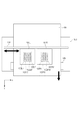
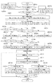
図1は、本発明の一実施形態に係るインクジェットプリンタを模式的に示す図である。本実施形態のインクジェットプリンタは、記録材として複数色のインクを用いて、記録媒体上に画像を記録する。ここでは、無彩色のインクであるブラックのインクと、有彩色のインクであるシアン、マゼンタ、イエローのカラーインクを用いる。図に示すように、プリンタ100は、プリンタの構造材をなすフレーム上に、記録部として記録ヘッドを2つ備える。ここでは、図中左側の記録ヘッドを101L、右側の記録ヘッドを101Rとする。記録ヘッド101Lには記録チップが配置され、記録チップにはインクを吐出するための記録素子群が設けられている。本実施形態の記録素子は、ヒータなどの発熱体によりインクを加熱して発泡させてインクを吐出する発熱素子であり、それぞれノズル内に設けられている。記録チップには、インク色毎にノズル列が設けられ、それぞれブラック(102LK)、シアン(102LC)、マゼンタ(102LM)、イエロー(102LY)である。同様に、記録ヘッド101Rにも、記録ヘッド101Lに搭載されたインクと同色のインクを吐出するための記録素子群が設けられた記録チップが配置されている。図のように、記録ヘッド101Rのノズル列を、ブラック(102RK)、シアン(102RC)、マゼンタ(102RM)、イエロー(102RY)とする。
FIG. 1 is a diagram schematically illustrating an inkjet printer according to an embodiment of the present invention. The ink jet printer according to the present embodiment records an image on a recording medium using a plurality of colors of ink as a recording material. Here, black ink, which is an achromatic color ink, and cyan, magenta, and yellow color inks, which are chromatic color inks, are used. As shown in the figure, the
プリンタ100は、いわゆるシリアル記録タイプのプリンタである。記録ヘッド101L及び記録ヘッド101Rには、記録用紙106の幅方向(図中X方向)に対して90度交差する方向(図中Y方向)に複数のノズルが配列される。これらの記録ヘッドを、ガイド104に沿ってX方向(走査方向)に往復走査させることにより、記録用紙106に画像を記録する。それぞれのインク色のノズル列のノズル配置の解像度は1200dpi(dot per inch)である。すなわち、Y方向に1/1200inchの間隔でノズルが配置されている。
The
記録媒体としての記録用紙106は、図中Y方向(搬送方向)に給紙され、搬送される。記録用紙106の搬送は、モータ(不図示)の駆動力によって搬送ローラ105(および他の不図示のローラ)が回転することによって行われる。記録用紙106が給紙されると、記録データに応じて、記録ヘッド101L及び記録ヘッド101Rのノズル群からインクが吐出され、図中Y方向のノズル列の長さに対応した1走査分の幅の画像が記録される。そして、1回の走査による記録が終わると、再びノズル列の長さに対応した幅だけ搬送され、再度記録ヘッドの走査により1走査分の幅の画像が記録される。このような記録用紙の搬送と各記録ヘッドからのインク吐出動作を繰り返すことにより、記録媒体上に画像を記録することができる。
A
図2は、図1に記載のプリンタ100が、記録ヘッド101Lと記録ヘッド101Rを用いて記録用紙106に画像を形成する様子を説明するための図である。図中、101L、102LK、102LC、102LM、102LY、101R、102RK、102RC、102RM、102RYは、それぞれ図1で説明したものと同じであるため、説明を省略する。103LK、103LC、103LM、103LYは、記録ヘッド101Lに搭載された、それぞれブラック、シアン、マゼンタ、イエローのインクを貯留するインクタンクである。各色のインクタンクは、対応する色のノズルと接続され、ノズルにインクを供給する。同様に、103RK、103RC、103RM、103RYは、記録ヘッド101Rに搭載された、それぞれブラック、シアン、マゼンタ、イエローのインクタンクである。本実施形態のインクタンクは、ブラックのタンクと、シアン、マゼンタ、イエローの3色のカラーインクのタンクが一体となっている構成であり、この一体型のインクタンクが左右の記録ヘッドに1つずつ搭載される。従って、4色のインクのいずれかが無くなった場合には、一体型のインクタンクに他色のインクが残っていたとしても、まとめて交換する必要がある。
FIG. 2 is a diagram for explaining how the
図2中の直線X1,X2,X3,X4は、記録用紙106の紙面上での記録ヘッドの走査方向(X方向)の位置を表している。本実施形態のインクジェットプリンタは、記録媒体上の領域を記録ヘッド101Lと記録ヘッド101Rで分担して記録する。X1は記録ヘッド101Lが記録可能な領域の左端、X2は記録ヘッド101Rが記録可能な領域の左端、X3は記録ヘッド101Lが記録可能な領域の右端、X2は記録ヘッド101Rが記録可能な領域の右端である。図中、領域A1及びA2は、記録用紙106の紙面上でのX方向の領域を表している。A1は記録ヘッド101Lを用いて記録可能な領域、A2は記録ヘッド101Rを用いて記録可能な領域である。そして、A3は記録ヘッド101Lのみが記録可能な領域、A5は記録ヘッド101Rのみが記録可能な領域であり、A4は記録ヘッド101Lと記録ヘッド101Rの両方を用いて記録可能な領域である。以下、本明細書において領域A4を重複領域と呼ぶ。
Lines X1, X2, X3, and X4 in FIG. 2 represent positions of the recording head in the scanning direction (X direction) on the surface of the
図1に示すプリンタ100により、領域A3は記録ヘッド101Lによって記録され、領域A5は記録ヘッド101Rによって記録され、領域A4は記録ヘッド101Lと記録ヘッド101Rの両方によって記録される。ここで、領域A4の記録方法としては、例えば、以下の3つの例が考えられる。(1)記録ヘッド101Lと記録ヘッド101Rを50%ずつ用いて記録する。(2)記録ヘッド101Lを用いて領域A4中の所定のX位置よりも左側を記録し、記録ヘッド101Rを用いてX位置よりも右側を記録する。(3)領域A4中の左側になる程記録ヘッド101Lを多く用いて記録し、右側になる程記録ヘッド101Rを多く用いて記録する様に、記録割合を段階的に変えて記録する。本発明は、上記の方法のいずれを用いてもよい。
With the
図3は、本実施形態に係る記録システムの構成例を示すブロック図である。同図に示すように、この記録システムは、図1に示したプリンタ100と、そのホスト装置としてのパーソナルコンピュータ(PC)300を有して構成される。
FIG. 3 is a block diagram illustrating a configuration example of the recording system according to the present embodiment. As shown in the figure, the recording system includes the
ホストPC300は、主に以下の要素を有して構成される。CPU301は、HDD303やRAM302に保持されているプログラムに従った処理を実行する。RAM302は、揮発性のストレージであり、プログラムやデータを一時的に保持する。また、HDD303は、不揮発性のストレージであり、同じくプログラムやデータを保持する。データ転送I/F(インターフェース)304はプリンタ100との間におけるデータの送受信を制御する。このデータ送受信の接続方式としては、USB、IEEE1394、LAN等を用いることができる。キーボード・マウスI/F305は、キーボードやマウス等のHID(Human Interface Device)を制御するI/Fであり、ユーザは、このI/Fを介して入力をすることができる。ディスプレイI/F306は、ディスプレイ(不図示)における表示を制御する。
The
一方、プリンタ100は、主に以下の要素を有して構成される。CPU311は、ROM313やRAM312に保持されているプログラムに従い、図4以降で後述する各処理を実行することで、本発明のデータ生成装置として機能する。RAM312は、揮発性のストレージであり、プログラムやデータを一時的に保持する。また、ROM313は不揮発性のストレージであり、図4以降で後述する各処理で作成されるテーブルデータやプログラムを保持することができる。
On the other hand, the
データ転送I/F314はPC300との間におけるデータの送受信を制御する。ヘッドコントローラ315Lは、図1に示した記録ヘッド101Lに対して記録データを供給するとともに、記録ヘッド101Lの吐出動作を制御する。具体的には、ヘッドコントローラ315Lは、RAM312の所定のアドレスから制御パラメータと記録データを読み込む構成とすることができる。そして、CPU311が、制御パラメータと記録データをRAM312の上記所定のアドレスに書き込むと、ヘッドコントローラ315Lにより処理が起動され、記録ヘッド101Lからのインク吐出が行われる。同様に、ヘッドコントローラ315Rは、図1に示した記録ヘッド101Rに対して記録データを供給するとともに、記録ヘッド101Rの吐出動作を制御する。画像処理アクセラレータ316は、ハードウェアによって構成され、CPU311よりも高速に画像処理を実行するものである。具体的には、画像処理アクセラレータ316は、RAM312の所定のアドレスから画像処理に必要なパラメータとデータを読み込む構成とすることができる。そして、CPU311が上記パラメータとデータをRAM312の上記所定のアドレスに書き込むと、画像処理アクセラレータ316が起動され、所定の画像処理が行われる。尚、画像処理アクセラレータ316は必ずしも必要な要素ではく、プリンタの仕様などに応じて、CPU311による処理のみで上記のテーブルパラメータの作成処理および画像処理を実行してもよいことはもちろんである。
The data transfer I /
以上説明した記録システムにおいて、いずれか1つのタンク内のインクが無くなってしまうまでの記録量を増加させる処理を以下に説明する。 In the recording system described above, processing for increasing the recording amount until ink in any one of the tanks runs out will be described below.
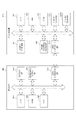
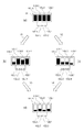
図4は、各インクタンクのインクの残量を示す図である。図4(a)は、記録ヘッド101Lを記録装置に装着した直後の状態を示している。ブラックインクタンク103LK、シアンインクタンク103LC、マゼンタインクタンク103LM、イエローインクタンク103LYのそれぞれのインク残量は、ほぼ満杯である。
FIG. 4 is a diagram showing the remaining amount of ink in each ink tank. FIG. 4A shows a state immediately after the
ここで、図4(a)の状態から、記録ヘッド101Lを用いて、主に黒及びグレーの文字が含まれる原稿を一定量記録した場合には、図中V1で示す遷移が発生し、図4(b)の状態に遷移する。逆に、記録ヘッド101Lを用いて、主にカラー画像が含まれる原稿を一定量記録した場合には、図中V2で示す遷移が発生し、図4(c)の状態に遷移する。
Here, from the state of FIG. 4A, when a certain amount of a document including mainly black and gray characters is recorded using the
図4(b)は、記録ヘッド101Lを用いて、主に黒及びグレー文字が含まれる原稿を一定量記録した後のインク残量の例を表している。ブラックインクタンク103LKの残量が最も少ない。一方、他のカラーインクのタンク、すなわち、シアンインクタンク103LC、マゼンタインクタンク103LM、イエローインクタンク103LYの残量はいずれも、ブラックインクタンク103LKの残量よりも多い。このまま記録を続けると、ブラックインクが一番先にインク切れとなる可能性が高い。
FIG. 4B shows an example of the remaining amount of ink after a certain amount of an original mainly containing black and gray characters is recorded using the
図4(c)は、記録ヘッド101Lを用いて、主にカラー画像が含まれる原稿を一定量記録した後のインク残量の例を表している。ブラックインクタンク103LKの残量が最も多く、他のカラーインクのインクタンクの残量はいずれも、ブラックインクタンク103LKの残量よりも少ない。すなわち、ブラックインクとカラーインクにおけるインク残量の偏りが大きい。従って、このまま記録を続けると、いずれかのカラーインク、本例ではイエローインクが一番先にインク切れとなる可能性が高い。
FIG. 4C illustrates an example of the remaining amount of ink after recording a certain amount of a document mainly including a color image using the
ここで、本発明は以下の2つの事項のうちいずれかを実現することが目標である。1つめは、図4(b)の状態から、カラーインクの使用比率を上げることで図中V3に示す遷移を行い、図4(d)の状態に遷移する。2つめは、図4(c)の状態から、ブラックインクの使用比率を上げることで図中V4に示す遷移を行い、図4(d)の状態に遷移する。 Here, the present invention aims to realize one of the following two matters. First, from the state of FIG. 4B, by increasing the color ink usage ratio, a transition indicated by V3 in the figure is performed, and a transition is made to the state of FIG. 4D. Second, from the state shown in FIG. 4C, the transition to the state shown in FIG. 4D is performed by increasing the usage ratio of the black ink to perform the transition indicated by V4 in the figure.
図4(d)は本発明の目標とするインク残量の例を表す図である。ブラックインクタンク103LKと比べて、シアンインクタンク103LC、マゼンタインクタンク103LM、イエローインクタンク103LYのうち、少なくとも1色はブラックインクと同程度に残量が少ない。すなわち、ブラックインクとカラーインクにおけるインク残量の偏りが小さい。従って、このまま記録を続けると、ブラックインクとカラーインクのいずれか、例えばマゼンタインクがインク切れとなった際には、他のインクも同等にほぼ使い切っている可能性が高い。 FIG. 4D is a diagram showing an example of the remaining amount of ink targeted by the present invention. Compared to the black ink tank 103LK, at least one of the cyan ink tank 103LC, the magenta ink tank 103LM, and the yellow ink tank 103LY has a small remaining amount as much as the black ink. That is, the deviation of the remaining amount of ink between the black ink and the color ink is small. Therefore, if the recording is continued as it is, when either the black ink or the color ink, for example, the magenta ink is used up, there is a high possibility that the other ink is almost completely used up.
以上の様に、図4(d)に示す状態となるようにインクの使用方法を制御することで、図4(a)に示すような記録ヘッドに搭載されるインクを有効に使用することができる。その制御の結果、搭載されたタンクを用いた記録量を増加させることが出来る。 As described above, it is possible to effectively use the ink mounted on the recording head as shown in FIG. 4A by controlling the method of using the ink so that the state shown in FIG. it can. As a result of the control, the recording amount using the mounted tank can be increased.
図5は、本実施形態における処理フローである。本フローは、図1中のプリンタ100に搭載される記録ヘッド101L、記録ヘッド101Rでの領域分割時の処理フローである。
FIG. 5 is a processing flow in the present embodiment. This flow is a processing flow at the time of area division in the
印字フローがSTARTすると、ステップs5001aで、使用している記録ヘッド101Lについて、新品のヘッドが搭載された直後であるかどうかを判断する。新品のヘッドが搭載された直後であると判断された場合にはステップs5002aに進み、当該ヘッドで記録したDot数をリセットし、ステップs5001bに進む。ステップs5001aで、新品のヘッドでは無く、継続使用されているヘッドであると判断された場合は、これまでの記録Dot数を継続して用いるため、そのままステップs5001bに進む。
When the print flow is START, in step s5001a, it is determined whether or not the
ステップs5001bで、使用している記録ヘッド101Rについて、新品のヘッドが搭載された直後であるかどうかを判断する。新品のヘッドが搭載された直後であると判断された場合にはステップs5002bに進み、当該ヘッドで記録したDot数をリセットし、ステップs5003に進む。ステップs5001bで、新品のヘッドでは無く、継続使用されているヘッドであると判断された場合は、これまでの記録Dot数を継続して用いるため、そのままステップs5003に進む。
In step s5001b, it is determined whether or not the
ステップs5003では、左右の記録ヘッドそれぞれのブラックインクの残存率を計算する。
Rem_LK=(Max_K−Dot_LK)/Max_K
Rem_RK=(Max_K−Dot_RK)/Max_K
ここで、Rem_LKは、記録ヘッド101L側のブラックインクの残存率を表し、1.0が満杯、0.0がインク切れを表す。Rem_RKは、記録ヘッド101R側のブラックインクの残存率を表し、同様に1.0が満杯、0.0がインク切れを表す。
In step s5003, the remaining ratio of black ink in each of the left and right recording heads is calculated.
Rem_LK = (Max_K−Dot_LK) / Max_K
Rem_RK = (Max_K−Dot_RK) / Max_K
Here, Rem_LK represents the remaining ratio of black ink on the
Max_Kは、ブラックのインクタンクが満杯の場合に、記録できる最大画素数、すなわち吐出できる最大Dot数を表す定数であり、インクタンクの大きさと記録ヘッドの吐出量等によって決定される。本実施形態においては、Max_Kは記録ヘッド101L及び記録ヘッド101Rで共通である。
Max_K is a constant representing the maximum number of pixels that can be recorded when the black ink tank is full, that is, the maximum number of dots that can be ejected, and is determined by the size of the ink tank, the ejection amount of the recording head, and the like. In the present embodiment, Max_K is common to the
Dot_LKは、インクタンクと一体に形成された記録ヘッド101Lが新品の状態で装着されてから判断時までに、ブラックインクを吐出した数(Dot数)である。同様に、Dot_RKは、インクタンクと一体に形成された記録ヘッド101Rが新品の状態で装着されてから判断時までに、ブラックインクを吐出した数(Dot数)である。
Dot_LK is the number of ejected black inks (Dot number) from when the
次に、ステップs5004では、カラーインクの残存率を計算する。
Rem_LCol=min((Max_C−Dot_LC)/Max_C,(Max_M−Dot_LM)/Max_M,(Max_Y−Dot_LY)/Max_Y)
Rem_RCol=min((Max_C−Dot_RC)/Max_C,(Max_M−Dot_RM)/Max_M,(Max_Y−Dot_RY)/Max_Y)
ここで、Rem_LColは、記録ヘッド101L側のカラーインクの残存率を表し、1.0が満杯、0.0がインク切れを表す。同様に、Rem_RColは、記録ヘッド101R側のカラーインクの残存率を表し、1.0が満杯、0.0がインク切れを表す。Max_C、Max_M、Max_Yは、それぞれシアン、マゼンタ、イエローインクの満杯時の各色のインクで吐出できる最大のドット数を表す定数であり、インクタンクの大きさと記録ヘッドの吐出量等によって決定される。本実施形態において、Max_C、Max_M、Max_Yは記録ヘッド101L及び記録ヘッド101Rで共通である。
Next, in step s5004, the remaining ratio of the color ink is calculated.
Rem_LCol = min ((Max_C-Dot_LC) / Max_C, (Max_M-Dot_LM) / Max_M, (Max_Y-Dot_LY) / Max_Y)
Rem_RCol = min ((Max_C-Dot_RC) / Max_C, (Max_M-Dot_RM) / Max_M, (Max_Y-Dot_RY) / Max_Y)
Here, Rem_LCol represents the remaining ratio of the color ink on the
Dot_LC、Dot_LM、Dot_LYは、記録ヘッド101Lが新品の状態で装着されてから判断時までに吐出した各インク色のドット数である。本実施形態において、Rem_LColはシアン、マゼンタ、イエローのインク残存率の最小値であり、タンク内の残量が最も少ない色の残存率となる。
Dot_LC, Dot_LM, and Dot_LY are the number of dots of each ink color ejected from when the
Dot_RC、Dot_RM、Dot_RYは、記録ヘッド101Rが新品の状態で装着されてから判断時までに吐出した各インク色のドット数である。本実施形態において、Rem_RColはシアン、マゼンタ、イエローのインク残存率の最小値であり、タンク内の残量が最も少ない色の残存率となる。
Dot_RC, Dot_RM, and Dot_RY are the number of dots of each ink color ejected from when the
次に、ステップs5005aでは、記録ヘッド101L側のブラックインクの残量に比べて、記録ヘッド101L側のカラーインクの残量が所定量以上多いかどうかを判定する。本実施形態では、ブラックインクの残量がカラーインクの残量の1.2倍よりも多いかどうかを判定する。
Rem_LK>Rem_LCol * 1.2
Next, in step s5005a, it is determined whether or not the remaining amount of color ink on the
Rem_LK> Rem_LCol * 1.2
ここで、判定結果がYesの場合、例えばブラックインクの残量がカラーインクの残量の1.5倍の量である場合、ブラックインクに比べてカラーインクが大幅に少なくなっている状況である。このとき、ステップs5007aへ進み、後述の色分解処理で用いる記録ヘッド101L側の色分解テーブルを、「ブラックインクを多く使う色分解テーブル」に設定し、ステップs5005bに進む。
Here, when the determination result is Yes, for example, when the remaining amount of black ink is 1.5 times the remaining amount of color ink, the color ink is greatly reduced compared to the black ink. . At this time, the process proceeds to step s5007a, the color separation table on the
ステップs5005aにおける判定結果がNoの場合、ステップs5006aへ進む。ステップs5006aでは、記録ヘッド101L側のカラーインクの残量に比べて、記録ヘッド101L側のブラックインクの残量が所定量以上多いかどうかを判定する。本実施形態では、カラーインクの残量がブラックインクの残量の1.2倍よりも多いかどうかを判定する。
Rem_LCol>Rem_LK * 1.2
If the determination result in step s5005a is No, the process proceeds to step s5006a. In step s5006a, it is determined whether or not the remaining amount of black ink on the
Rem_LCol> Rem_LK * 1.2
ここで、判定結果がYesの場合、例えばカラーインクの残量がブラックインクの残量の1.5倍の量である場合には、カラーインクに比べてブラックインクが大幅に少なくなっている状況である。このとき、ステップs5009aへ進み、後述の色分解処理で用いる記録ヘッド101L側の色分解テーブルを、「カラーインクを多く使う色分解テーブル」に設定し、ステップs5005bに進む。
Here, when the determination result is Yes, for example, when the remaining amount of the color ink is 1.5 times the remaining amount of the black ink, the black ink is significantly reduced compared to the color ink. It is. At this time, the process proceeds to step s5009a, the color separation table on the
ステップs5006aにおける判定結果がNoの場合、記録ヘッド101Lにおけるブラックインクの残量とカラーインクの残量は、互いに他方の1.2倍以下の関係にある。すなわち、ブラックインクの残量とカラーインクの残量がほぼ同等である場合で、残量の差が小さい状況である。このとき、ステップs5008aへ進み、後述の色分解処理で用いる記録ヘッド101L側の色分解テーブルを、「標準の色分解テーブル」に設定し、ステップs5005bに進む。
When the determination result in step s5006a is No, the remaining amount of black ink and the remaining amount of color ink in the
尚、ステップs5005a及びステップs5006aにおいて判定に用いた定数1.2や判定式は一例であり、他の定数や判定方法を用いてもよい。本図の例では、ブラックインクの残量とカラーインクの残量の比率で判定したが、例えば、残量の差が所定量以下であるかどうかを判定してもよく、より残量の多いインクをより多く使う色分解テーブルを選択するものであればよい。また、記録ヘッド101Lと記録ヘッド101Rで、異なる定数や異なる判定方法を用いてもよい。
Note that the constant 1.2 and the determination formula used for determination in steps s5005a and s5006a are examples, and other constants and determination methods may be used. In this example, the determination is made based on the ratio between the remaining amount of black ink and the remaining amount of color ink. However, for example, it may be determined whether the difference between the remaining amounts is equal to or less than a predetermined amount. Any color separation table that uses more ink may be selected. Further, different constants and different determination methods may be used for the
次に、ステップs5005b〜s5009bでは、ステップs5005a〜s5009aと同様の処理を行う。ここでは、記録ヘッド101R側のブラックインクの残量と記録ヘッド101R側のカラーインクの残量を比較し、残量の差が所定量以下であるかどうかを判定する。
Next, in steps s5005b to s5009b, processing similar to that in steps s5005a to s5009a is performed. Here, the remaining amount of black ink on the
各工程における処理内容は記録ヘッド101Lの場合と同様であり、ブラックインクとカラーインクの残量の差が大きい場合には、多く残っている方のインクを多く使うような色分解テーブルを設定する。以下の判定式を用いる。
ステップs5005b:Rem_RK>Rem_RCol * 1.2
ステップs5006b:Rem_RCol>Rem_RK * 1.2
以上の処理において、記録ヘッド101Lで記録する領域用の色分解テーブルと、記録ヘッド101Rで記録する領域用の色分解テーブルが設定される。
The processing contents in each process are the same as in the case of the
Step s5005b: Rem_RK> Rem_RCol * 1.2
Step s5006b: Rem_RCol> Rem_RK * 1.2
In the above processing, the color separation table for the area to be recorded by the
ステップs5005b〜s5009bが終了すると、ステップs5010に進む。ステップs5010〜ステップs5015では、実際に原稿の画像データを画像処理し、記録媒体に記録する。 When steps s5005b to s5009b are completed, the process proceeds to step s5010. In steps s5010 to s5015, the image data of the original is actually processed and recorded on a recording medium.
ステップs5010では、原稿のRGB画像を入力する。ステップs5011では、原稿のRGBの色を、記録に好適なRGB値に変換する、色補正処理を行う。この色補正処理は既知の好適な処理を用いて構わない。 In step s5010, an RGB image of the document is input. In step s5011, color correction processing is performed to convert the RGB color of the document into RGB values suitable for recording. This color correction process may use a known suitable process.
ステップs5012では、LRヘッド色分解処理及びLRヘッドデータ分割処理を行う。ここでは、ステップs5011において変換されたRGBデータを、記録ヘッド101Lおよび記録ヘッド101Rそれぞれから吐出する、ブラック、シアン、マゼンタ、イエローの各インクの使用量を示すデータに変換する処理が行われる。尚、色分解処理の手法としては、既知の好適な処理を用いて構わない。本実施形態では、説明を簡単にするため、色分解処理の入力値をRin、Gin、Binとする。そして、記録ヘッド101Lの出力値をLKout、LCout、LMout、LYout、記録ヘッド101Rの出力値をRKout、RCout、RMout、RYoutとし、以下の計算式に従って処理される。ここで、Rin、Gin、BinおよびLKout、LCout、LMout、LYout、RKout、RCout、RMout、RYoutはそれぞれ8bitの値であり、その値域は0から255とする。
In step s5012, LR head color separation processing and LR head data division processing are performed. Here, processing for converting the RGB data converted in step s5011 into data indicating the usage amount of each ink of black, cyan, magenta, and yellow discharged from the
C=255−Rin
M=255−Gin
Y=255−Bin
K=min(C,M,Y)
C’=C−K
M’=M−K
Y’=Y−K
ここから、図2中の領域A3、A4、A5のそれぞれに対して、処理が異なるので、詳細に説明する。
C = 255-Rin
M = 255-Gin
Y = 255-Bin
K = min (C, M, Y)
C ′ = C−K
M ′ = M−K
Y '= YK
From here, the processing is different for each of the regions A3, A4, and A5 in FIG. 2 and will be described in detail.
領域A3においては、以下の式で算出される。 In the area A3, the following formula is used.
LKout= LK_Table[K]
LCout=C’+LC_Table[K]
LMout=M’+LM_Table[K]
LYout=Y’+LY_Table[K]
(RKout,RCout,RMout,RYout=0)
ここで、LK_Table、LC_Table、LM_Table、LY_Tableはそれぞれ、グレー画像における必要濃度Kを実現するために、ブラック、シアン、マゼンタ、イエローの各インクをどの位用いるかを設定するための色分解テーブルである。これらの色分解テーブルは、記録ヘッド101L用のテーブルであり、上述のステップs5007a、ステップs5008a、ステップs5009aで設定されたものを用いる。
そして、各テーブルに入力された値に基づいて出力された値を用いて、各値を算出する。
LKout = LK_Table [K]
LCout = C ′ + LC_Table [K]
LMout = M ′ + LM_Table [K]
LYout = Y ′ + LY_Table [K]
(RKout, RCout, RMout, RYout = 0)
Here, LK_Table, LC_Table, LM_Table, and LY_Table are color separation tables for setting how much each of the black, cyan, magenta, and yellow inks is used to achieve the necessary density K in the gray image. . These color separation tables are tables for the
And each value is calculated using the value output based on the value input into each table.
領域A5においては、以下の式で算出される。
RKout= RK_Table[K]
RCout=C’+RC_Table[K]
RMout=M’+RM_Table[K]
RYout=Y’+RY_Table[K]
(LKout,LCout,LMout,LYout=0)
ここで、RK_Table、RC_Table、RM_Table、RY_Tableはそれぞれ、グレー画像における必要濃度Kを実現するために、ブラック、シアン、マゼンタ、イエローの各インクをどの位用いるかを設定するための色分解テーブルである。これらの色分解テーブルは、記録ヘッド101R用の色分解テーブルであり、上述のステップs5007b、ステップs5008b、ステップs5009bで設定されたものを用いる。
In the area A5, the following formula is used.
RKout = RK_Table [K]
RCout = C ′ + RC_Table [K]
RMout = M ′ + RM_Table [K]
RYout = Y ′ + RY_Table [K]
(LKout, LCout, LMout, LYout = 0)
Here, RK_Table, RC_Table, RM_Table, and RY_Table are color separation tables for setting how much each of the black, cyan, magenta, and yellow inks is used to achieve the necessary density K in the gray image. . These color separation tables are the color separation tables for the
領域A4においては、以下の式で算出される。
LKout=LK_Table[K] x a1+RK_Table[K] x b1
LCout=(C’+LC_Table[K]) x a2+(C’+RC_Table[K]) x b2
LMout=(M’+LM_Table[K]) x a3+(M’+RM_Table[K]) x b3
LYout=(Y’+LY_Table[K]) x a4+(Y’+RY_Table[K]) x b4
RKout=LK_Table[K] x c1+RK_Table[K] x d1
RCout=(C’+LC_Table[K]) x c2+(C’+RC_Table[K]) x d2
RMout=(M’+LM_Table[K]) x c3+(M’+RM_Table[K]) x d3
RYout=(Y’+LY_Table[K]) x c4+(Y’+RY_Table[K]) x d4
ここで、a1〜a4、b1〜b4、c1〜c4、d1〜d4はそれぞれ係数である。重複領域である記録領域A4の記録に、記録ヘッド101Lと記録ヘッド101Rをそれぞれどのような割合で用いるかによって適宜決定される。
In the area A4, the following formula is used.
LKout = LK_Table [K] xa1 + RK_Table [K] xb1
LCout = (C ′ + LC_Table [K]) × a2 + (C ′ + RC_Table [K]) × b2
LMout = (M ′ + LM_Table [K]) × a3 + (M ′ + RM_Table [K]) × b3
LYout = (Y ′ + LY_Table [K]) × a4 + (Y ′ + RY_Table [K]) × b4
RKout = LK_Table [K] x c1 + RK_Table [K] x d1
RCout = (C ′ + LC_Table [K]) × c2 + (C ′ + RC_Table [K]) × d2
RMout = (M ′ + LM_Table [K]) × c3 + (M ′ + RM_Table [K]) × d3
RYout = (Y ′ + LY_Table [K]) × c4 + (Y ′ + RY_Table [K]) × d4
Here, a1 to a4, b1 to b4, c1 to c4, and d1 to d4 are coefficients. It is determined appropriately depending on the ratio of the
記録領域A4の記録方法として3種類の例を上述したが、それぞれに対しては、例えば以下の様に設定することで、好適な記録が行える。 Three examples of the recording method for the recording area A4 have been described above, and suitable recording can be performed for each of the recording areas by setting the following, for example.
1.記録ヘッド101Lと記録ヘッド101Rを50%ずつ用いて記録する。
a1〜a4=0.25, b1〜b4=0.25
c1〜c4=0.25, d1〜d4=0.25
と設定することで、記録インク量を左右の記録ヘッドを均等に用いることができる。
1. Recording is performed using the
a1 to a4 = 0.25, b1 to b4 = 0.25
c1-c4 = 0.25, d1-d4 = 0.25
With this setting, the recording ink amount can be used equally between the left and right recording heads.
2.領域A4中の所定のX位置よりも左側を記録ヘッド101L、右側を記録ヘッド101Rで記録する。所定のX位置よりも左側の画素を記録する際は、以下の様に設定する。
a1〜a4=1.00, b1〜b4=0.00
c1〜c4=0.00, d1〜d4=0.00
2. The left side of the predetermined X position in the area A4 is recorded by the
a1-a4 = 1.00, b1-b4 = 0.00
c1 to c4 = 0.00, d1 to d4 = 0.00
所定のX位置よりも右側の画素を記録する際は、以下のように設定する。
a1〜a4=0.00, b1〜b4=0.00
c1〜c4=0.00, d1〜d4=1.00
When recording a pixel on the right side of the predetermined X position, the following setting is made.
a1-a4 = 0.00, b1-b4 = 0.00
c1 to c4 = 0.00, d1 to d4 = 1.00
3.領域A4中の左側程記録ヘッド101L、右側程記録ヘッド101Rで記録する様に、記録割合を段階的に変えて記録する。
a1〜a4=(w−x)/w * (w−x)/w,
b1〜b4=x /w * (w−x)/w,
c1〜c4=x /w * x /w,
d1〜d4=(w−x)/w * , x /w
ここで、wは、領域A4の幅に対応する画素数、xは、処理対象画素の領域A4左端からの画素位置(画素数)を示している。従って、領域A4の左端において、x=0であり、領域A4の右端において、x=wである。
3. In the area A4, the recording rate is changed stepwise so that the
a1 to a4 = (w−x) / w * (w−x) / w,
b1-b4 = x / w * (w−x) / w,
c1 to c4 = x / w * x / w,
d1 to d4 = (w−x) / w *, x / w
Here, w is the number of pixels corresponding to the width of the area A4, and x is the pixel position (number of pixels) from the left end of the area A4 of the processing target pixel. Accordingly, x = 0 at the left end of the region A4 and x = w at the right end of the region A4.
本ステップs5012の結果として、記録ヘッド101Lの出力データとしては図2中の領域A3+A5のLKout、LCout、LMout、LYoutが出力される。また、記録ヘッド101Rの出力データとしては図2中の領域A5+A4のRKout、RCout、RMout、RYoutが出力される。
As a result of step s5012, LKout, LCout, LMout, and LYout in the area A3 + A5 in FIG. 2 are output as output data of the
上述の説明において、係数a1〜a4、b1〜b4、c1〜c4、d1〜d4は、記録媒体の紙面上にドットが理想的に配置され、インク滲みが十分に少ない場合に記録領域A5に対して好適に画像を記録するための数値の一例である。本発明の効果を得る上では必ずしも上述の係数を用いる必要は無い。実際のプリンタ100での記録において、ドットの記録状態のばらつきやインク滲みに応じて、適宜好適な係数を設定することができる。
In the above description, the coefficients a1 to a4, b1 to b4, c1 to c4, and d1 to d4 are relative to the recording area A5 when dots are ideally arranged on the paper surface of the recording medium and ink bleeding is sufficiently small. It is an example of the numerical value for recording an image suitably. In order to obtain the effects of the present invention, it is not always necessary to use the above-described coefficients. In actual recording with the
また、本実施形態においては、係数a1〜a4、b1〜b4、c1〜c4、d1〜d4を用いて出力値を算出する例を説明したが、それらの係数を反映した、入力出力変換テーブルを記録画素位置毎に予め用意し、演算に使用してもよい。 Moreover, in this embodiment, although the example which calculates an output value using the coefficients a1-a4, b1-b4, c1-c4, d1-d4 was demonstrated, the input output conversion table which reflected those coefficients was used. It may be prepared in advance for each recording pixel position and used for calculation.
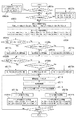
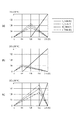
図7は、本実施形態の色分解処理で用いる変換データの例を説明する図である。この色分解処理により、入力された画像データに基づいて、各インクの付与量を示すデータが生成される。各変換データは、必要濃度0から必要濃度255へのグレー画像への色分解するための変換テーブルである。数値が小さいほど低濃度、数値が大きいほど高濃度のグレー色であり、255が最高濃度である。本図の説明において、記録ヘッド101L用の色分解テーブルと記録ヘッド101R用の色分解テーブルは共通のテーブルが適用可能であるため、K_Table、C_Table、M_Table、Y_Tableと記載して説明する。尚、ここで説明する色分解テーブルは、CMYK値の入力に対してCMYK値を出力する変換テーブルであり、ここで示す横軸は、0〜255の256階調のブラック(K)の値である。これは、C=M=Y=0であるグレー画像である。縦軸は、C、M、Y、Kの出力値であり、各インクの付与量に関する値である。尚、本発明で用いる色分解テーブルは、入力値はCMYK値に限るものではなく、RGB値であってもよい。RGB値の入力の場合は、グレー画像はR=G=Bの場合であり、横軸はR、G、Bのいずれかの値を用いればよい。
FIG. 7 is a diagram illustrating an example of conversion data used in the color separation process according to the present embodiment. By this color separation processing, data indicating the applied amount of each ink is generated based on the input image data. Each conversion data is a conversion table for color separation from a required
図7(a)は、ステップs5008a及びステップs5008bで設定される、「標準の色分解テーブル」を表している。横軸は、グレー画像における必要濃度Kであり、縦軸は、グレー画像において必要濃度Kを実現するために用いるブラック、シアン、マゼンタ、イエローの各インクの付与量を表している。図7(a)では、グレー必要濃度0から128の低階調側では、シアン、マゼンタ、イエローのカラーインクのみでグレー画像を実現し、その量はそれぞれ単調増加する。すなわち、ブラックインクの付与量は0である。そして、中間階調(中間濃度)からブラックインクの付与量が0より大きくなる。必要濃度129から254まではブラックインクとカラーインクの両方を用いてグレー画像を実現する。高階調側では、ブラックインクの付与量は単調増加し、カラーインクの付与量は単調減少する。最高濃度である必要濃度255は、カラーインクを用いずにブラックインクのみでグレー画像を実現する。
FIG. 7A shows a “standard color separation table” set in steps s5008a and s5008b. The horizontal axis represents the required density K in the gray image, and the vertical axis represents the applied amount of each of the black, cyan, magenta, and yellow inks used to achieve the required density K in the gray image. In FIG. 7A, a gray image is realized only with cyan, magenta, and yellow color inks on the low gradation side where the gray required density is 0 to 128, and the amount thereof monotonously increases. That is, the amount of black ink applied is zero. Then, the applied amount of black ink becomes larger than 0 from the intermediate gradation (intermediate density). From the required density 129 to 254, a gray image is realized using both black ink and color ink. On the high gradation side, the black ink application amount monotonously increases, and the color ink application amount monotonously decreases. The required
図7(b)は、ステップs5007a及びステップs5007bで設定される、「ブラックインクを多く使う色分解テーブル」を表す図である。各線とインク色との関係は、図7(a)と同様である。図7(b)では、グレー必要濃度0から64では、カラーインクのみの単調増加でグレー画像を実現し、必要濃度65から254までは、単調増加するブラックインクと単調減少するカラーインクの両方を用いてグレー画像を実現する。必要濃度255では、ブラックインクのみでグレー画像を実現する。図7(b)を図7(a)と比べると、例えばK=192のとき、図7(b)のテーブルは、図7(a)のテーブルに比べて、K_Table[K]の値が大きい。そして、図7(b)のテーブルは、図7(a)のテーブルに比べて、C_Table[K]、M_Table[K]、Y_Table[K]の値が小さい。また、図7(b)のテーブルは、図7(a)のテーブルに比べて、より低い階調値からK_Table[K]の値が0より大きくなる。これは、グレー画像の記録において、より低い階調値、すなわちより低濃度側のグレー色からブラックインクを付与するデータが生成されることを示している。このため、グレー画像を記録した場合に、期待値としてカラーインクよりもブラックインクの方がより多く使われる可能性が高いと言える。
FIG. 7B is a diagram illustrating a “color separation table that uses a lot of black ink” set in steps s5007a and s5007b. The relationship between each line and ink color is the same as in FIG. In FIG. 7B, a gray image is realized by monotonically increasing only the color ink at the gray required density of 0 to 64, and both the black ink that monotonously increases and the color ink that monotonously decreases from the required density of 65 to 254. To achieve a gray image. At the required
図7(c)は、ステップs5009a及びステップs5009bで設定される、「カラーインクを多く使う色分解テーブル」を表す図である。各線とインク色との関係は、図7(a)と同様である。図7(c)では、グレー必要濃度0から192まではカラーインクのみの単調増加でグレー画像を実現する。必要濃度193から254までは、単調減少するブラックインクと単調増加するカラーインクの両方を用いてグレー画像を実現し、最高濃度である必要濃度255ではブラックインクのみでグレー画像を実現する。図7(c)を図7(a)と比べると、例えばK=192のとき、図7(c)のテーブルは、図7(a)のテーブルに比べて、K_Table[K]の値が小さい。そして、図7(c)のテーブルは、図7(a)のテーブルに比べて、C_Table[K]、M_Table[K]、Y_Table[K]の値が大きい。また、図7(c)のテーブルは、図7(a)のテーブルに比べて、より高い階調値からK_Table[K]の値が0より大きくなる。これは、グレー画像の記録において、より高い階調値、すなわちより高濃度のグレー色からブラックインクを付与するデータが生成されることを示している。このため、グレー画像を記録した場合に、期待値としてブラックインクよりもカラーインクの方がより多く使われる可能性が高いと言える。
FIG. 7C illustrates a “color separation table that uses a lot of color ink” set in steps s5009a and s5009b. The relationship between each line and ink color is the same as in FIG. In FIG. 7C, a gray image is realized by monotonically increasing only the color ink from the required gray density of 0 to 192. For the required densities 193 to 254, a gray image is realized using both monotonically decreasing black ink and monotonically increasing color ink, and at the required
ここで、図5の処理フローの説明に戻る。ステップs5013aでは、記録ヘッド101L側のインク付与量を示す、LKout、LCout、LMout、LYoutの各データを、実際に記録するDotの有無を示すDotデータに変換する量子化処理を行う。このDotの有無が、記録ヘッド101Lの各ノズルからのインクの吐出または非吐出の指示を示している。同様に、ステップs5013bでは、記録ヘッド101R側のインク付与量を示す、RKout、RCout、RMout、RYoutを、実際に記録するDotの有無を示すDotデータに変換する量子化処理を行う。このDotの有無が、記録ヘッド101Rの各ノズルからのインクの吐出または非吐出の指示を示している。尚、量子化処理は、既知の誤差拡散処理やディザ処理等、いかなる手法を用いても構わない。量子化されたDotデータが記録ヘッドに送られて、記録ヘッドの1走査分のDotデータの準備が完了したら、記録用紙106上に記録ヘッド101Lと記録ヘッド101Rを用いた実際の画像記録が行われる。
Now, the description returns to the processing flow of FIG. In step s5013a, quantization processing is performed to convert each data of LKout, LCout, LMout, and LYout indicating the ink application amount on the
ステップs5014aでは、記録ヘッド101L用に量子化されたDotデータに基づいて、以下の演算式により、Dot数をカウントして累積処理を行う。
Dot_LK +=Count_LK
Dot_LC +=Count_LC
Dot_LM +=Count_LM
Dot_LY +=Count_LY
ここで、Count_LK、Count_LC、Count_LM、Count_LYは、記録ヘッド101L側のそれぞれのインク色の記録Dot数である。
In step s5014a, based on the dot data quantized for the
Dot_LK + = Count_LK
Dot_LC + = Count_LC
Dot_LM + = Count_LM
Dot_LY + = Count_LY
Here, Count_LK, Count_LC, Count_LM, and Count_LY are the number of recording dots of each ink color on the
同様に、ステップs5014bでは、記録ヘッド101R用に量子化されたDotデータに基づいて、以下の演算式により、Dot数をカウントして累積処理を行う。
Dot_RK +=Count_RK
Dot_RC +=Count_RC
Dot_RM +=Count_RM
Dot_RY +=Count_RY
ここで、Count_RK、Count_RC、Count_RM、Count_RYは記録ヘッド101R側のそれぞれのインク色の記録Dot数である。
Similarly, in step s5014b, based on the dot data quantized for the
Dot_RK + = Count_RK
Dot_RC + = Count_RC
Dot_RM + = Count_RM
Dot_RY + = Count_RY
Here, Count_RK, Count_RC, Count_RM, and Count_RY are the number of recording dots of each ink color on the
本実施形態では、画像の記録を目的として記録用紙106上に吐出する際のインク以外のインク消費については便宜上考慮していない。しかし、記録媒体外に吐出する所謂予備吐出等、画像の記録を目的としないインク消費を考慮することにより、インク残量の推定精度をさらに高めることができる。
In this embodiment, the consumption of ink other than ink when ejecting onto the
ステップs5015では、記録すべき画像データの全ての画素について処理が完了したかを判定する。判定結果がYesの場合には本フローは終了する。そして、これまで累積計算されたDot_LK、Dot_LC、Dot_LM、Dot_LY情報、及び、Dot_RK、Dot_RC、Dot_RM、Dot_RY情報は、メモリに記憶され、次に原稿の印字命令が入った際に用いられる。ステップs5015での判定結果がNoの場合にはステップs5010に戻り、原稿の続きを処理することとなる。以後、最後の画素まで、ステップs5010〜ステップs5015が繰り返される。 In step s5015, it is determined whether the processing has been completed for all the pixels of the image data to be recorded. If the determination result is Yes, this flow ends. The Dot_LK, Dot_LC, Dot_LM, Dot_LY information, and Dot_RK, Dot_RC, Dot_RM, and Dot_RY information accumulated so far are stored in the memory and used when a document printing command is input next time. If the determination result in step s5015 is No, the process returns to step s5010 to process the continuation of the document. Thereafter, steps s5010 to s5015 are repeated until the last pixel.
以上説明したように、記録ヘッド101Lおよび記録ヘッド101Rからインクが吐出された回数をカウントすることにより、各インク色の消費量を積算する。そして、インク色毎に算出された消費量に基づいて、インク色毎のインクタンク内の残量を推定する。そして、推定結果を取得し、取得した結果に基づいて、各記録ヘッドについて、ブラックインクとカラーインクのうち残量率が相対的に多い方をより多く使うように設計された色分解テーブルを設定する。これにより、記録ヘッド101L及び記録ヘッド101Rそれぞれにおいて、ブラックインクとカラーインクの消費率を近付けることができる。この結果、いずれかのタンク内のインクが先に無くなり、記録が出来なくなってしまうまでの記録量を増加させることが可能となる。
As described above, the consumption amount of each ink color is integrated by counting the number of times ink is ejected from the
さらに、図4(b)及び(c)のような、ブラックインクの残量とカラーインクの残量のいずれか一方が他方に対して大幅に少なくなってしまった状況では、インク切れ以外の要因で画質を低下させてしまう可能性がある。それは、「インク中の水分の蒸発に伴う濃縮」である。タンク内のインクの体積に対する空気の体積の比率が大きくなればなるほど、インク中の水分の蒸発が促進する。図4(b)の状態においては、ブラックインクのタンク103LKにおける空気の体積がカラーインクの各タンクにおける空気の体積よりも大きいため、インク中の水分の蒸発が多くなり、ブラックインクの濃縮が進む。これにより、ブラックインクの記録濃度が高くなってしまう。同様に、図4(c)の状態においては、カラーインク中の水分の蒸発がより多くなるため、カラーインクの記録濃度が高くなってしまう。 Further, in the situation where either one of the remaining amount of black ink and the remaining amount of color ink is significantly smaller than the other as shown in FIGS. May reduce the image quality. That is “concentration accompanying evaporation of moisture in the ink”. As the ratio of the volume of air to the volume of ink in the tank increases, the evaporation of moisture in the ink is promoted. In the state of FIG. 4B, since the volume of air in the black ink tank 103LK is larger than the volume of air in each tank of color ink, the evaporation of water in the ink increases and the concentration of the black ink proceeds. . This increases the recording density of the black ink. Similarly, in the state shown in FIG. 4C, the evaporation of water in the color ink is increased, so that the recording density of the color ink is increased.
このようなインクの濃縮により、白から黒へのグラデーションを有するグレー画像において、なめらかな階調性が損なわれるという課題がある。図7(a)に示すように、グレー画像の低階調側ではシアン、マゼンタ、イエローのカラーインクのみを用いて記録され、中間階調からはカラーインクの付与量が減少し、ブラックインクの付与量が増加する。ここで、カラーインクの残量が少なく、カラーインクのタンクにおいて水分の蒸発による濃縮が進んでいる場合には、低階調画像における記録濃度は、設計された記録濃度よりも高くなる。そして、中間階調から高階調側にかけてカラーインクの付与量とブラックインクの付与量の大小関係が入れ替わる際に、本来濃度が上がるべき階調であっても、カラーインクの付与量が少なくなるにつれて記録濃度が下がってしまう場合がある。このように、インクの濃縮によって、本来は単調増加すべき記録濃度が増減し、階調の連続性が得られず、記録画像の画質が低下してしまう可能性がある。同様に、ブラックインクの残量が少なく、ブラックインクのタンクにおいて蒸発による濃縮が進んでいる場合には、中間階調における記録濃度が設計された記録濃度よりも高くなってしまう。これにより、高階調側の記録画像における階調性が低下してしまう可能性がある。 Due to such ink concentration, there is a problem that smooth gradation is impaired in a gray image having a gradation from white to black. As shown in FIG. 7A, recording is performed using only cyan, magenta, and yellow color inks on the low gradation side of the gray image, and the amount of color ink applied decreases from the intermediate gradation, and the black ink Grant amount increases. Here, when the remaining amount of the color ink is small and the concentration by evaporation of water proceeds in the color ink tank, the recording density in the low gradation image becomes higher than the designed recording density. Then, when the magnitude relationship between the color ink application amount and the black ink application amount is switched from the intermediate gradation level to the high gradation side, even if the density should be increased, the color ink application amount decreases. The recording density may decrease. As described above, due to the concentration of ink, the recording density that should be monotonously increased originally increases or decreases, and there is a possibility that the continuity of gradation cannot be obtained and the image quality of the recorded image is deteriorated. Similarly, when the black ink remaining amount is small and the concentration by evaporation is proceeding in the black ink tank, the recording density at the intermediate gradation is higher than the designed recording density. As a result, there is a possibility that the gradation in the recorded image on the high gradation side is deteriorated.
このような課題に対し、本発明は、ブラックインク及びカラーインクのインク消費率の偏りを小さくし、互いに近づけることを目標としているため、上述したような水分の蒸発に起因する記録画像のなめらかな階調性を維持するという効果も得ることができる。 In order to deal with such problems, the present invention aims to reduce the deviation in the ink consumption rates of the black ink and the color ink and bring them closer to each other. Therefore, the recording image resulting from the evaporation of moisture as described above is smooth. An effect of maintaining gradation can also be obtained.
尚、本実施形態では、図2に示したように、領域A4を重複領域として、記録ヘッド101L及び記録ヘッド101Rの両方を用いて記録する例を用いて説明した。本発明は、領域A4を設けない記録方式であっても適用可能である。すなわち、記録ヘッド101Lで記録可能な領域A1が、記録ヘッド101Lのみで記録する領域A3と等しく、記録ヘッド101Rで記録可能な領域A2が、記録ヘッド101Rのみで記録する領域A5と等しい場合である。このとき、左右の記録ヘッドを用いて記録する領域A4が存在せず、領域A1と領域A2が重ならずに隣接する。このような構成であっても、本実施形態と同じ効果を得ることができる。
In the present embodiment, as shown in FIG. 2, the area A4 is used as an overlapping area, and the recording is performed using both the
(第2の実施形態)
第1の実施形態では、記録ヘッド101L及び記録ヘッド101Rのそれぞれに対して個別に消費率を制御するケースについて説明した。本実施形態では、記録ヘッド101Lと記録ヘッド101Rの両方のインク残量に基づいて、インク消費率を制御するケースについて説明する。
(Second Embodiment)
In the first embodiment, the case where the consumption rate is individually controlled for each of the
図7で説明した「標準の色分解テーブル」、図7(b)で説明した「ブラックインクを多く使う色分解テーブル」、図7(c)で説明した「カラーインクを多く使う色分解テーブル」は、本来極力同じ濃度、同じ色味を実現する様に設計されている。一方、大量生産されるインクジェットプリンタにおいて、記録ヘッドの吐出量は必ずしも一定では無い。そのため、記録ヘッドの吐出量が理想値からずれている場合には、図7に示した上記3つのテーブルを用いた場合に、同一濃度であっても記録画像の色味が異なってしまう。 “Standard color separation table” described in FIG. 7, “Color separation table using a lot of black ink” described in FIG. 7B, “Color separation table using a lot of color ink” described in FIG. Is originally designed to achieve the same density and color as much as possible. On the other hand, in an inkjet printer that is mass-produced, the ejection amount of the recording head is not necessarily constant. Therefore, when the ejection amount of the recording head deviates from the ideal value, the color of the recorded image is different even when the same density is used when the above three tables shown in FIG. 7 are used.
さらに、ブラック、シアン、マゼンタ、イエローの各インクの使用比率の差異が大きい程、この記録画像の色味の差が大きくなる傾向がある。これについて以下に説明する。「標準の色分解テーブル」を用いて、所定のグレー濃度を色分解したデータに基づいてプリンタで記録した画像の色をAとする。同様に、「ブラックインクを多く使う色分解テーブル」を用いて、所定のグレー濃度を色分解したデータに基づいてプリンタで記録した画像の色をBとする。同様に、「カラーインクを多く使う色分解テーブル」を用いて、所定のグレー濃度を色分解したデータに基づいてプリンタで記録した画像の色をCとする。このとき、AとBの色差をΔA−B、AとCの色差をΔA−C、BとCの色差をΔB−Cとすると、以下の関係が成り立つ。
ΔA−B<ΔB−C
ΔA−C<ΔB−C
Further, as the difference in use ratio of each ink of black, cyan, magenta, and yellow increases, the difference in color of the recorded image tends to increase. This will be described below. Let A be the color of an image recorded by a printer based on data obtained by color separation of a predetermined gray density using the “standard color separation table”. Similarly, the color of an image recorded by a printer based on data obtained by color separation of a predetermined gray density using a “color separation table that uses a lot of black ink” is defined as B. Similarly, the color of an image recorded by a printer based on data obtained by color separation of a predetermined gray density using a “color separation table using a large amount of color ink” is defined as C. At this time, if the color difference between A and B is ΔA−B, the color difference between A and C is ΔA−C, and the color difference between B and C is ΔB−C, the following relationship holds.
ΔA-B <ΔB-C
ΔA-C <ΔB-C
すなわち、「ブラックインクを多く使う色分解テーブル」と「カラーインクを多く使う色分解テーブル」との組み合わせが、使用するインクの比率の差が相対的に大きいため、色むらとして視認されやすい。 In other words, the combination of the “color separation table that uses a lot of black ink” and the “color separation table that uses a lot of color ink” has a relatively large difference in the ratio of the inks used, and thus is easily visually recognized as color unevenness.
そこで、本実施形態では、図2中の記録領域A3と記録領域A4の色味の差が認識されにくい範囲内で、記録可能量を増加させることを目標とする。 Therefore, in this embodiment, the target is to increase the recordable amount within a range in which the color difference between the recording area A3 and the recording area A4 in FIG.
図6は、本実施形態での処理フローを示すフローチャートである。図6中のステップs6001〜ステップs6015は、図5中のステップs5001〜ステップs5015と処理内容が同じであるため、説明を省略する。本実施形態と第1の実施形態との違いは、ステップs6007b、s6008b、s0609bとステップs6010の間に、ステップs6016が存在する点である。ステップs6016では、記録ヘッド101L用と記録ヘッド101R用のインク色分解テーブルが設定された状態で、左右の記録ヘッドで記録される記録用紙106上の色味の差を所定量以下に抑える「左右差制限処理」を行う。
FIG. 6 is a flowchart showing a processing flow in the present embodiment. Steps s6001 to s6015 in FIG. 6 have the same processing contents as steps s5001 to s5015 in FIG. The difference between this embodiment and the first embodiment is that step s6016 exists between steps s6007b, s6008b, s0609b, and step s6010. In step s6016, with the ink color separation tables for the
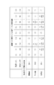
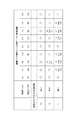
図9は、本実施形態の左右差制限処理を説明するための表である。記録ヘッド101Lには、ステップs6007a〜s6009aのいずれかで色分解テーブルが設定される。図7(a)の「Std(標準)」、図7(b)の「Bk(ブラックインクを多く使う)」、図7(c)の「Col(カラーインクを多く使う)」の3種類の色分解テーブルのいずれかである。同様に、記録ヘッド101Rには、ステップs6007b〜s6009bのいずれかで色分解テーブルが設定され、同様に「Std」、「Bk」、「Col」の3種類のいずれかである。従って、記録ヘッド101L用に設定された色分解テーブルと記録ヘッド101R用に設定された色分解テーブルの組み合わせは、「個別ヘッド用のインク分解テーブル設定結果」に示すように9通りとなる。この9通りの組み合わせに対し、本図には、使用する記録媒体の種類に応じて最終的にどのようなインク分解テーブルが用いられるべきかを記載している。各欄の「○」印は、色分解テーブルを変更せずに使用しても良いことを示しており、各欄の「×」印は、色分解テーブルの変更が必要であることを示している。
FIG. 9 is a table for explaining the left / right difference limiting process of the present embodiment. A color separation table is set in the
まず、記録用紙106の記録用紙種別が「普通紙」である場合について説明する。普通紙では色味の差が視認されづらいため、いずれの場合も「○」である。すなわち、ステップs6007a〜s6009aのいずれか、及び、ステップs6007b〜6009bのいずれかで設定された色分解テーブルをそのまま使うことを意味する。
First, a case where the recording paper type of the
次に、記録用紙106の記録用紙種別が「マット紙」である場合について説明する。マット紙では、色差が最も大きい「Bk」と「Col」のテーブルを隣接する領域で用いると色むらとして視認されてしまう。従って、この組み合わせには設定せず、いずれか一方を「Std」に変更する。本例では、記録ヘッド101L用の色分解テーブルが「Bk」、記録ヘッド101R用の色分解テーブルが「Col」の場合には、記録ヘッド101L用は「Bk」のままとし、記録ヘッド101R用を「Std」に変更する。また、記録ヘッド101L用の色分解テーブルが「Col」、記録ヘッド101R用の色分解テーブルが「Bk」の場合には、記録ヘッド101L用を「Std」に変更し、記録ヘッド101R用を「Bk」のままとする。尚、記録ヘッド101L用の色分解テーブルと記録ヘッド101R用の色分解テーブルが同じ組み合わせである場合には、変更せずにそのまま設定する。
Next, a case where the recording paper type of the
次に、記録用紙106の記録用紙種別が「光沢紙」である場合について説明する。ここで例示した「普通紙」「マット紙」「光沢紙」の3種類の中で、光沢紙は、異なる色分解テーブルを用いた場合の色差が最も視認されやすい紙種である。よって、本例では、上記フローで左右の記録ヘッドに対して異なる色分解テーブルが選択された場合には、いずれも「Std」に変更する。すなわち、記録ヘッド101L用の色分解テーブルと記録ヘッド101R用の色分解テーブルが共に「Bk」、共に「Std」、共に「Col」の場合には、色分解テーブルをそのままとする。それ以外の組み合わせの場合には、記録ヘッド101L用の色分解テーブルと記録ヘッド101R用の色分解テーブルを、共に「Std」に変更する。
Next, a case where the recording paper type of the
一般的に、「普通紙」、「マット紙」、「光沢紙」の紙種に記録可能な色域は、「普通紙」、「マット紙」、「光沢紙」の順に広くなる。従って、異なる色分解テーブルを用いた際の色味のずれも、「普通紙」、「マット紙」、「光沢紙」の順に大きくなる。 In general, the color gamuts that can be recorded on the “plain paper”, “matte paper”, and “glossy paper” paper types are increased in the order of “plain paper”, “matte paper”, and “glossy paper”. Accordingly, the color shift when using different color separation tables increases in the order of “plain paper”, “matte paper”, and “glossy paper”.
ここで、一般的に、測色結果から算出されるΔEが3.2以下である場合、人間の目には同じ色と認識される、とされている。また、印象レベルではΔEが6.5以下であれば同程度の色と認識される、とされている。従って、本実施形態では、色差の許容限界値を6.5とした。そこで、図9は以下の状況を前提に「左右差制限処理」を行う場合を表している。
普通紙 :図7(b)と図7(c)の色味のずれ<色味差許容限界
マット紙:図7(a)と図7(b)の色味のずれ<色味差許容限界
図7(a)と図7(c)の色味のずれ<色味差許容限界
図7(b)と図7(c)の色味のずれ>色味差許容限界
光沢紙 :図7(a)と図7(b)の色味のずれ>色味差許容限界
図7(a)と図7(c)の色味のずれ>色味差許容限界
Here, generally, when ΔE calculated from the color measurement result is 3.2 or less, it is considered that the same color is recognized by human eyes. In addition, in the impression level, if ΔE is 6.5 or less, the same color is recognized. Therefore, in this embodiment, the allowable limit value of the color difference is set to 6.5. FIG. 9 shows a case where the “left / right difference limiting process” is performed based on the following situation.
Plain paper: Color deviation in FIGS. 7B and 7C <color difference tolerance limit Matte paper: Color deviation in FIGS. 7A and 7B <color difference tolerance limit
Discoloration of FIG. 7A and FIG. 7C <color difference tolerance limit
7 (b) and FIG. 7 (c) Color deviation> Tint difference tolerance limit Glossy paper: Color deviation of FIGS. 7 (a) and 7 (b)> Tint difference tolerance limit
Discoloration difference between FIG. 7 (a) and FIG. 7 (c)> Allowable color difference limit
以上の構成により、左右の記録ヘッドで記録された画像の色味の差を許容範囲内に抑えつつ、搭載されたタンクを用いた記録量を増加させる。尚、本実施形態は、一例として「普通紙」においては左右の記録ヘッドでいずれの色分解テーブルを用いても色味差許容限界に収まる例を記載したが、色分解テーブルの設計や左右の記録ヘッドの特性に応じて適宜設定することが可能である。 With the above configuration, the recording amount using the mounted tank is increased while suppressing the difference in color of the images recorded by the left and right recording heads within an allowable range. In this embodiment, as an example, in the case of “plain paper”, an example in which any color separation table is used with the right and left recording heads is within the color difference tolerance limit is described. It is possible to set appropriately according to the characteristics of the recording head.
尚、前述の説明では、記録領域A3と記録領域A4の色味の差が視認されづらいような場合について説明したが、記録領域A4の幅が0である場合でも、本実施形態は適用可能である。すなわち、記録ヘッド101Lの記録領域A1と記録ヘッド101Rの記録領域A2が重複しない場合である。記録媒体の種別による色味の差の視認されやすさは上述したような関係にあるため、重複しない場合であっても上記構成により、本実施形態と同じ効果を得ることができる。
In the above description, the case where it is difficult to visually recognize the color difference between the recording area A3 and the recording area A4 has been described. However, the present embodiment is applicable even when the width of the recording area A4 is zero. is there. That is, the recording area A1 of the
(第2の実施形態の変形例)
第2の実施形態では、図6中のステップs6016の「左右差制限処理」の具体的な処理として、記録用紙種別に応じて「色味差許容限界」内で色分解テーブルを設定する例を説明したが、本変形例では、「繋ぎ幅」に応じて設定する例を説明する。
(Modification of the second embodiment)
In the second embodiment, as a specific process of the “left / right difference limiting process” in step s6016 in FIG. 6, an example in which a color separation table is set within the “tone difference allowable limit” according to the recording paper type. As described above, in this modification, an example in which the setting is made according to the “connection width” will be described.
一般的に、人間の目は色味の急峻な変化には敏感であり、緩やかな変化には鈍感である。よって、記録ヘッド101Lと記録ヘッド101Rの色分解テーブルが異なっていても、両方の記録ヘッドを用いて記録する領域において、各記録ヘッドの使用比率を段階的に変化させることで色味の差を視認されづらくすることができる。具体的には、図2における記録領域A4に対して、領域の中心から左端に近づくほど記録ヘッド101Lを多く用いて記録し、且つ、領域の中心から右端に近づくほど記録ヘッド101Rを多く用いて記録する様に、記録割合を段階的に変化させる。このとき、記録領域A4の幅、いわゆる「繋ぎ幅」が狭い場合には色味の変化が急峻となり、「繋ぎ幅」が広い場合には色味の変化が緩やかとなる。
In general, the human eye is sensitive to steep changes in color and insensitive to gradual changes. Therefore, even if the color separation tables of the
図10は、本変形例における「左右差制限処理」を示す図である。左右の記録ヘッドのテーブルが設定されるところまでは、前述の図9と同じであるので説明を省略する。そして、記録用紙106の記録用紙幅が「A4サイズ」、「2Lサイズ」、「Lサイズ」の場合について、最終的に用いられる色分解テーブルが記されている。
FIG. 10 is a diagram illustrating the “left / right difference limiting process” in the present modification. The steps up to the point where the left and right recording head tables are set are the same as those in FIG. A color separation table to be finally used is described for the case where the recording paper width of the
ここでは、一例として、記録用紙が「Lサイズ」の場合について説明する。Lサイズの記録用紙の幅は3.5inchであるため、各記録領域の幅の関係は以下のようになる。
領域A3+領域A4+領域A5=3.5inch
ここで、
領域A3の幅=領域A5の幅=1.5inch
領域A4の幅=0.5inch
とする。つまり、記録ヘッド101Lと記録ヘッド101Rが同時に駆動する際の左右の記録ヘッド間距離は1.5inchとなる。
Here, as an example, a case where the recording paper is “L size” will be described. Since the width of the L-size recording paper is 3.5 inches, the relationship between the widths of the recording areas is as follows.
Region A3 + region A4 + region A5 = 3.5 inch
here,
Width of region A3 = width of region A5 = 1.5 inch
Area A4 width = 0.5 inch
And That is, the distance between the left and right recording heads when the
この左右の記録ヘッド間距離(1.5inch)で、「2Lサイズ」の記録用紙を記録する場合は、記録用紙の幅が5.0inchであるため、各記録領域の幅の関係は以下のようになる。 When recording a “2L size” recording sheet at the distance between the left and right recording heads (1.5 inches), the width of the recording sheet is 5.0 inches, and the relationship between the widths of the recording areas is as follows. become.
領域A3+領域A4+領域A5=5.0inch
領域A4の幅=2.0inch
また、この左右の記録ヘッド間距離で、「A4サイズ」の記録用紙を記録する場合は、記録用紙の幅が8.5inchであるため、各記録領域の幅の関係は以下のようになる。
Area A3 + area A4 + area A5 = 5.0 inch
Area A4 width = 2.0 inch
Further, when recording an “A4 size” recording sheet with the distance between the left and right recording heads, the width of the recording sheet is 8.5 inches, and the relationship between the widths of the recording areas is as follows.
領域A3+領域A4+領域A5=8.5inch
領域A4の幅=5.5inch
以上の様に、「A4サイズ」、「2Lサイズ」、「Lサイズ」における各記録領域A4の幅は、「A4サイズ」「2Lサイズ」「Lサイズ」の順に狭い。前述したように、左右の記録ヘッドにそれぞれ異なる色分解テーブルを用いた場合、吐出量ばらつきに起因して、記録領域A3と記録領域A5に色味の差が生じる。この色味の差は、記録領域A4の幅が広いほど変化の傾きが小さくなるため、視認されづらくなる。従って、色味の差の急峻さは、「A4サイズ」、「2Lサイズ」、「Lサイズ」の順に大きくなり、視認されやすい。そこで、図10は以下の状況を前提に「左右差制限処理」を行う場合を表している。
A4サイズ:図7(b)と図7(c)の色味の変化の急峻さ<許容限界
2Lサイズ:図7(a)と図7(b)の色味の変化の急峻さ<許容限界
図7(a)と図7(c)の色味の変化の急峻さ<許容限界
図7(b)と図7(c)の色味の変化の急峻さ>許容限界
Lサイズ :図7(a)と図7(b)の色味の変化の急峻さ>許容限界
図7(a)と図7(c)の色味の変化の急峻さ>許容限界
このように、記録領域A4の幅が大きくなるにつれて左右の記録ヘッド間の色味の差が視認されづらくなるため、許容幅を大きく設定することができる。以上の構成により、左右の色味の差を許容範囲差に抑えながら、いずれか1つのタンク内のインクが無くなり、記録が出来なくなってしまうまでに記録可能量を増加させることが出来る。
Region A3 + region A4 + region A5 = 8.5 inch
Area A4 width = 5.5 inch
As described above, the width of each recording area A4 in “A4 size”, “2L size”, and “L size” is narrower in the order of “A4 size”, “2L size”, and “L size”. As described above, when different color separation tables are used for the left and right recording heads, a difference in color occurs between the recording area A3 and the recording area A5 due to the discharge amount variation. This color difference is less visible because the change area becomes smaller as the recording area A4 is wider. Therefore, the steepness of the color difference increases in the order of “A4 size”, “2L size”, and “L size”, and is easily visually recognized. FIG. 10 shows a case where the “left / right difference limiting process” is performed based on the following situation.
A4 size: steepness of color change in FIGS. 7B and 7C <
Steepness of color change in FIG. 7A and FIG. 7C <allowable limit
Steepness of color change in FIGS. 7B and 7C> allowable limit L size: Steepness of color change in FIGS. 7A and 7B> allowable limit
Steepness of color change in FIGS. 7A and 7C> allowable limit As described above, as the width of the recording area A4 increases, the difference in color between the left and right recording heads becomes difficult to be visually recognized. Therefore, the allowable width can be set large. With the above configuration, it is possible to increase the recordable amount until ink in any one of the tanks disappears and recording becomes impossible while suppressing the difference between the left and right color tones within an allowable range.
尚、上述の例では、記録ヘッド101Lと記録ヘッド101Rを同時に駆動する際の左右の記録ヘッド間距離は1.5inchとしたが、この距離は任意に設定可能である。また、紙種によって左右の記録ヘッド間距離を変更してもよい。
In the above-described example, the distance between the left and right recording heads when driving the
(第3の実施形態)
前述の第1及び第2の実施形態においては、図7(c)に記載の「カラーインクを多く使う色分解テーブル」におけるK=255の入力に対する出力値は、以下のようになっている。
Kout=255
Cout=0
Mout=0
Yout=0
(Third embodiment)
In the first and second embodiments described above, the output value for the input of K = 255 in the “color separation table that uses a lot of color ink” shown in FIG. 7C is as follows.
Kout = 255
Cout = 0
Mout = 0
Yout = 0
このとき、例えば「黒文字のみの原稿」を記録する場合には、色分解テーブルを変更したとしてもブラックインクの消費量が変化しない。このため、黒文字のみの原稿の記録指示が続く場合にはブラックインクのみを使用し続けるため、上記の方法で色分解テーブルを変更しても、ブラックインクが無くなることで記録ができなくなってしまうまでの記録可能量を増加させることはできていない。そこで本実施形態では、黒文字が多く含まれる原稿が続いた場合であっても、ブラックインクとカラーインクとの残量の差を低減し、記録可能な量を増加させる構成について説明する。 At this time, for example, in the case of recording “a document with only black characters”, the consumption of black ink does not change even if the color separation table is changed. For this reason, since the black ink only is used when an instruction to record a document containing only black characters continues, even if the color separation table is changed by the above method, until the black ink disappears, recording cannot be performed. The recordable amount of can not be increased. Therefore, in the present embodiment, a description will be given of a configuration that reduces the difference in remaining amount between the black ink and the color ink and increases the recordable amount even when a document including many black characters continues.
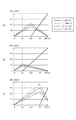
図8は、本実施形態で用いる色分解テーブルを示す図である。図8(a)及び図8(b)は、それぞれ図7(a)及び図7(b)と同じであるので説明を省略する。図8(c)は本実施形態での「カラーインクを多く使う色分解テーブル」であり、K=255の入力に対する出力値は、以下の値となる。
Kout=192
Cout=65
Mout=64
Yout=63
FIG. 8 is a diagram showing a color separation table used in the present embodiment. 8 (a) and 8 (b) are the same as FIGS. 7 (a) and 7 (b), respectively, so description thereof will be omitted. FIG. 8C is a “color separation table that uses a lot of color ink” in the present embodiment, and an output value for an input of K = 255 is as follows.
Kout = 192
Cout = 65
Mout = 64
Yout = 63
すなわち、「黒文字のみの原稿」であっても、ブラックインクだけでなく、カラーインクも用いて画像を記録する。これにより、ブラックインクの消費速度を抑え、ブラックインクが先に無くなるまでの記録可能量を増加させることができる。 That is, an image is recorded using not only black ink but also color ink even for a “black character only document”. As a result, the consumption rate of the black ink can be suppressed, and the recordable amount until the black ink disappears first can be increased.
以上のように、「黒文字のみの原稿」の記録指示が続き、ブラックインクの残量が少なくなってしまった場合には、最高濃度のグレー画像の記録においてもカラーインクを用いる。これにより、ブラックインクが先に無くなるまでの記録量を増加させることができる。但し、本実施形態では、K=255でのブラックインク使用量を192に減らした例を説明したが、ブラックインク使用量を減らしすぎると、左右の記録ヘッドで記録された画像間での記録濃度差が視認されやすくなるため、許容範囲差までに抑える。本実施形態においても、許容範囲はΔEが6.5以下とする。尚、許容範囲差までに抑える方法としては、第2の実施形態において説明したように、記録用紙種別に基づいて設定しても良い。また、第2の実施形態の変形例で説明したように、繋ぎ幅の広さに応じて許容範囲が異なるため、図2中の記録領域A4の幅に応じて設定しても良い。以上のように制御することで、左右の記録ヘッドで記録する画像の濃度差を許容範囲に収めつつ、搭載されたインクタンクを用いた記録量を増大させる。 As described above, when the recording instruction of “original document with only black characters” continues and the remaining amount of black ink is reduced, the color ink is also used in recording the gray image of the highest density. As a result, it is possible to increase the recording amount until the black ink disappears first. However, in this embodiment, the example in which the black ink usage amount at K = 255 is reduced to 192 has been described. However, if the black ink usage amount is reduced too much, the recording density between the images recorded by the left and right recording heads is described. Since the difference is easily visible, limit the difference to the allowable range. Also in this embodiment, the allowable range is that ΔE is 6.5 or less. Note that, as described in the second embodiment, the method of suppressing the difference to the allowable range difference may be set based on the recording paper type. Further, as described in the modification of the second embodiment, since the allowable range varies depending on the width of the connection width, it may be set according to the width of the recording area A4 in FIG. By controlling as described above, the recording amount using the mounted ink tank is increased while the density difference between the images recorded by the left and right recording heads is within the allowable range.
尚、前述の実施形態においては、ブラックインクのタンクと、複数色のカラーインクのタンクが一体に構成されたプリンタの例を説明したが、全色のインクタンクが一体に構成された構成以外であっても、本実施形態と同様の効果を得ることができる。例えば、複数色のカラーインクのうちの少なくとも1色のインクのタンクが、ブラックインクのタンクと一体に構成された場合や、各色のインクのタンクが別体に設けられた場合であってもよい。全ての色のインクのタンクが別体に構成された場合であっても、カラーインクのうち少なくとも一色のインクのタンクとブラックインクのタンクを一緒に交換する構成において、本発明は有効である。また、前述の実施形態では、記録チップとタンクが一体型に構成された記録ヘッドを記録装置から外して着脱可能に交換する形態の例を示した。この場合、一体型に構成されたいずれかの色のインクが無くなった場合、インクタンクだけでなく、記録チップを含む記録ヘッドごと交換しなければならないため、本発明の効果はさらに顕著なものとなる。また、記録素子が設けられた記録チップとインクタンクとが別体に構成され、インクタンクのみを外して交換する形態であってもよい。 In the above-described embodiment, an example of a printer in which a black ink tank and a plurality of color ink tanks are integrally configured has been described. However, other than the configuration in which all color ink tanks are integrally configured. Even if it exists, the effect similar to this embodiment can be acquired. For example, at least one color ink tank of a plurality of color inks may be integrated with a black ink tank, or each color ink tank may be provided separately. . The present invention is effective in a configuration in which at least one of the color ink tanks and the black ink tank are replaced together even when the ink tanks of all colors are configured separately. Further, in the above-described embodiment, an example in which the recording head in which the recording chip and the tank are integrated is removed from the recording apparatus and is detachably replaced is shown. In this case, when the ink of any color configured in the integrated type runs out, not only the ink tank but also the recording head including the recording chip must be replaced. Become. Further, the recording chip provided with the recording element and the ink tank may be configured separately, and only the ink tank may be removed and replaced.
また、左右の記録ヘッドは別体に形成されていてもよく、一体に形成されたものであってもよく、左右のチップが一体に形成されたものであってもよい。その場合、領域A1と領域A2を記録する同色のインクの記録素子の距離が、図2のX方向において、位置X1と位置X2の距離が所定距離離間していればよい。ここでの所定距離とは、左右の記録ヘッドが記録媒体上のX方向における領域を分担して記録するものであればよく、その距離は記録装置の構成及び記録媒体のサイズによって適宜決定することができる。 Further, the left and right recording heads may be formed separately, may be formed integrally, or may be formed integrally with the left and right chips. In that case, it is only necessary that the distance between the recording elements of the same color ink for recording the area A1 and the area A2 is a predetermined distance between the position X1 and the position X2 in the X direction of FIG. Here, the predetermined distance is not limited as long as the left and right recording heads share the area in the X direction on the recording medium, and the distance is appropriately determined depending on the configuration of the recording apparatus and the size of the recording medium. Can do.
また、各実施形態において、色分解テーブルを3種類用いて説明したが、色分解テーブルの種類は3種類に限定されず、より多い数のテーブルを用意してもよい。その場合には、ブラックインクとカラーインクの消費比率をより細かく制御することが出来る。また、図8及び図9で説明した左右差制限処理の詳細についても、色味差とインク消費比率をより細かく制御することが出来る。 In each embodiment, the description has been made using three types of color separation tables. However, the types of color separation tables are not limited to three types, and a larger number of tables may be prepared. In that case, the consumption ratio of the black ink and the color ink can be controlled more finely. Further, with respect to the details of the left / right difference limiting process described with reference to FIGS. 8 and 9, the color difference and the ink consumption ratio can be controlled more precisely.
また、第1の実施形態及び第2の実施形態で説明した、図5及び図6の処理フローにおいては、「原稿の終了」まで同一の色分解テーブルを継続して用い、「次の原稿の開始」の時に、色分解テーブルを再度設定している。この「原稿の終了」には、1ジョブ単位、1ページ単位、ページ内のオブジェクト単位、といずれの単位をあてはめても良く、それぞれメリットが存在する。1ジョブ単位で切り替える場合には、1ジョブで同一原稿を複数枚記録する際にそれら複数枚の原稿の記録画質を均質に保ちつつ、インク切れまでの記録可能な枚数を増加させることが出来る。1ページ単位で切り替える場合には、逆にページ間での色味の差を許容する代わりに、ジョブの途中でのインク切れの可能性を低減しつつ、ページ内の記録画質を均質に保つことが可能となる。また、ページ内のオブジェクト単位で切り替える場合には、ページ内での色味の差が生じる一方、ページ内でのインク切れの可能性を低減する、若しくはタンク内のインクが残り僅かな状態であっても、記録可能な範囲まで記録を行うことができる。このように、「原稿の終了」の定義は種々の設定が可能であり、ユーザの手動設定や、プリンタ本体の状況等による自動設定によって、適宜好適な方法を適用すれば良い。 In the processing flow of FIGS. 5 and 6 described in the first and second embodiments, the same color separation table is continuously used until “end of document”. At the time of “Start”, the color separation table is set again. This “end of document” may be applied to any unit such as a job unit, a page unit, or an object unit within a page, and each has a merit. When switching in units of one job, when a plurality of identical originals are recorded in one job, it is possible to increase the number of sheets that can be recorded until the ink runs out while maintaining the recording image quality of the plurality of originals uniform. When switching on a page-by-page basis, instead of allowing a difference in color between pages, the recording quality within the page is kept uniform while reducing the possibility of running out of ink during the job. Is possible. In addition, when switching in units of objects in the page, there is a difference in color within the page, while the possibility of running out of ink in the page is reduced, or the ink in the tank is in a very small state. However, recording can be performed up to a recordable range. In this way, the definition of “end of document” can be variously set, and a suitable method may be applied as appropriate depending on manual setting by the user or automatic setting according to the status of the printer main body.
また、図7及び図8に示した色分解テーブルは、低階調側をシアン、マゼンタ、イエローのカラーインクを用いてグレー画像を記録し、中間階調(中間濃度)からカラーインクとブラックインクを併用してグレー画像を記録するものであった。例えば、0〜255までの全階調において、カラーインクを用いずにブラックインクのみで記録を行うように定めた色分解テーブルを用いてもよい。このブラックインクのみの色分解テーブルは、ブラックインクの残量がカラーインクの残量よりも著しく多い場合に用いることで、インク残量の差を低減するという本発明の目的を達成することができる。また、色分解処理に用いる変換データとして色分解テーブルを用いたが、テーブル形式でなくてもよく、関数等で記憶する形態であってもよい。 The color separation table shown in FIGS. 7 and 8 records a gray image using color inks of cyan, magenta, and yellow on the low gradation side, and uses color ink and black ink from the intermediate gradation (intermediate density). In combination, a gray image was recorded. For example, a color separation table may be used in which recording is performed using only black ink without using color ink in all gradations from 0 to 255. This black ink only color separation table is used when the remaining amount of black ink is significantly higher than the remaining amount of color ink, thereby achieving the object of the present invention to reduce the difference in remaining ink amount. . Further, although the color separation table is used as the conversion data used for the color separation processing, the color separation table may not be in a table format but may be stored in a function.
尚、上述の実施形態では、プリンタ100において図5及び図6に示した各処理、すなわち、残量に関する情報の取得、及び、その情報を用いた色分解処理を行う形態について説明した。これらの工程をホストPC300側において行う形態であってもよく、ホストPC300とプリンタ100で各処理を分担して行う形態であってもよい。
In the above-described embodiment, a description has been given of a mode in which the
また、上述の実施形態では、量子化された2値の記録データに基づいて、記録Dot数をカウントすることにより残量を推定する方法を用いたが、残量を取得する手段としてはこの方法に限るものではない。例えば、センサを用いて残量を検出する方法であってもよく、インクタンク内のインクの残量を推定できるものであれば他の手段を用いてもよい。 Further, in the above-described embodiment, the method of estimating the remaining amount by counting the number of recorded dots based on the quantized binary recording data is used. It is not limited to. For example, a method of detecting the remaining amount using a sensor may be used, and other means may be used as long as the remaining amount of ink in the ink tank can be estimated.
101L 左側記録ヘッド
101R 右側記録ヘッド
106 記録媒体
101L Left
Claims (34)
前記第1タンクの前記無彩色のインクの残量と前記有彩色のインクの残量に関する第1情報と、前記第2タンクの前記無彩色のインクの残量と前記有彩色のインクの残量に関する第2情報と、を取得する取得手段と、
前記第1情報に基づいて前記第1領域に対する前記無彩色のインク及び前記有彩色のインクの付与量を示すデータを生成し、前記第2情報に基づいて前記第2領域に対する前記無彩色のインク及び前記有彩色のインクの付与量を示すデータを生成する生成手段と、
を備え、
前記第1タンクにおいて、前記有彩色のインクの残量が前記無彩色のインクの残量よりも多く且つその差が第1の量である場合、前記無彩色のインクの残量と前記有彩色のインクの残量との差が前記第1の量よりも少ない場合に比べて、所定の中間階調のグレー画像の記録のために生成されるデータは、前記無彩色のインクの付与量が少なく且つ前記有彩色のインクの付与量が多いことを示し、
前記第2タンクにおいて、前記有彩色のインクの残量が前記無彩色のインクの残量よりも多く且つその差が第2の量である場合、前記無彩色のインクの残量と前記有彩色のインクの残量との差が前記第2の量よりも少ない場合に比べて、所定の中間階調のグレー画像の記録のために生成されるデータは、前記無彩色のインクの付与量が少なく且つ前記有彩色のインクの付与量が多いことを示すことを特徴とするデータ生成装置。 A first area on a recording medium transported in the transport direction is formed using a first recording unit including a recording element group for ejecting each of achromatic ink and chromatic ink stored in a first tank. A recording element group for recording and discharging each of the achromatic color ink and the chromatic color ink stored in the second tank, and has a predetermined distance from the first recording unit in a scanning direction intersecting the transport direction; Data for recording a second area that is an area on the recording medium and that is adjacent to the first area in the scanning direction is generated by using a second recording section that is spaced apart. A data generator,
First information on the remaining amount of the achromatic color ink and the remaining amount of the chromatic color ink in the first tank, the remaining amount of the achromatic color ink and the remaining amount of the chromatic color ink in the second tank. Second information relating to, obtaining means for obtaining,
Data indicating the amount of the achromatic color ink and the chromatic color ink applied to the first region is generated based on the first information, and the achromatic color ink is applied to the second region based on the second information. And generating means for generating data indicating the applied amount of the chromatic color ink,
With
In the first tank, when the remaining amount of the chromatic color ink is larger than the remaining amount of the achromatic ink and the difference is the first amount, the remaining amount of the achromatic ink and the chromatic color Compared to the case where the difference from the remaining amount of ink is smaller than the first amount, the data generated for recording the gray image of the predetermined intermediate gradation has the amount of the achromatic ink applied. A small amount and a large amount of the chromatic ink applied;
In the second tank, when the remaining amount of the chromatic ink is larger than the remaining amount of the achromatic ink and the difference is the second amount, the remaining amount of the achromatic ink and the chromatic color Compared to the case where the difference from the remaining amount of ink is smaller than the second amount, the data generated for recording a gray image of a predetermined intermediate tone has the amount of achromatic ink applied. A data generation apparatus characterized by indicating that the amount of the chromatic color ink applied is small and large.
前記第2タンクにおいて、前記無彩色のインクの残量が前記有彩色のインクの残量よりも多く且つその差が第4の量である場合、前記無彩色のインクの残量と前記有彩色のインクの残量との差が前記第4の量よりも少ない場合に比べて、所定の中間階調のグレー画像の記録のために生成されるデータは、前記無彩色のインクの付与量が多く且つ前記有彩色のインクの付与量が少ないことを示すことを特徴とする請求項1に記載のデータ生成装置。 In the first tank, when the remaining amount of the achromatic ink is larger than the remaining amount of the chromatic ink and the difference is a third amount, the remaining amount of the achromatic ink and the chromatic color Compared to the case where the difference from the remaining amount of ink is smaller than the third amount, the data generated for recording a gray image of a predetermined intermediate tone has the amount of achromatic ink applied. A large amount and a small amount of the chromatic ink applied;
In the second tank, when the remaining amount of the achromatic ink is larger than the remaining amount of the chromatic ink and the difference is the fourth amount, the remaining amount of the achromatic ink and the chromatic color Compared to the case where the difference from the remaining amount of ink is smaller than the fourth amount, the data generated for recording the gray image of the predetermined intermediate gradation has the amount of the achromatic ink applied. The data generation apparatus according to claim 1, wherein the data generation apparatus indicates that the amount of the chromatic color ink applied is small.
前記第1タンクの前記有彩色のインクの残量と前記無彩色のインクの残量に関する第1情報と、前記第2タンクの前記有彩色のインクの残量と前記無彩色のインクの残量に関する第2情報と、を取得する取得手段と、
複数の変換データの中から、前記第1情報に基づいて前記第1領域用の変換データを設定し、前記第2情報に基づいて前記第2領域用の変換データを設定する設定手段と、
前記設定手段により設定された変換データに基づいて、前記第1領域及び前記第2領域のそれぞれに対する前記無彩色のインク及び前記有彩色のインクの付与量を示すデータを生成する生成手段と、
を備え、
前記設定手段により、前記第1タンクの前記有彩色のインクの残量が前記無彩色のインクの残量よりも所定量以上多い場合に設定される変換データは、前記第1タンクの前記有彩色のインクの残量が前記無彩色のインクの残量よりも所定量以上多くない場合に設定される変換データに比べて、グレー画像の記録において前記無彩色のインクを付与し始める濃度が低く設定されており、
前記設定手段により、前記第2タンクの前記有彩色のインクの残量が前記無彩色のインクの残量よりも所定量以上多い場合に設定される変換データは、前記第2タンクの前記有彩色のインクの残量が前記無彩色のインクの残量よりも所定量以上多くない場合に設定される変換データに比べて、グレー画像の記録において前記無彩色のインクを付与し始める濃度が低く設定されていることを特徴とするデータ生成装置。 A first area on a recording medium transported in the transport direction is formed using a first recording unit including a recording element group for ejecting each of chromatic color ink and achromatic color ink stored in a first tank. A recording element group for recording and ejecting each of the chromatic color ink and the achromatic color ink stored in the second tank, and has a predetermined distance from the first recording unit in a scanning direction intersecting the transport direction; A data generation apparatus for recording a second area including an area adjacent to the first area in the scanning direction using the second recording unit arranged at a distance from the second recording unit. There,
First information regarding the remaining amount of the chromatic color ink and the remaining amount of the achromatic color ink in the first tank, the remaining amount of the chromatic color ink and the remaining amount of the achromatic color ink in the second tank. Second information relating to, obtaining means for obtaining,
Setting means for setting conversion data for the first region based on the first information from among a plurality of conversion data, and setting the conversion data for the second region based on the second information;
Generating means for generating data indicating the amount of the achromatic color ink and the chromatic color ink applied to each of the first area and the second area based on the conversion data set by the setting means;
With
The conversion data set by the setting means when the remaining amount of the chromatic color ink in the first tank is greater than the remaining amount of the achromatic color ink by a predetermined amount is the chromatic color in the first tank. Compared to the conversion data set when the remaining amount of ink is not more than a predetermined amount more than the remaining amount of the achromatic ink, the density at which the achromatic ink starts to be applied is set lower when recording the gray image. Has been
The conversion data set by the setting means when the remaining amount of the chromatic color ink in the second tank is greater than the remaining amount of the achromatic color ink by a predetermined amount is the chromatic color in the second tank. Compared to the conversion data set when the remaining amount of ink is not more than a predetermined amount more than the remaining amount of the achromatic ink, the density at which the achromatic ink starts to be applied is set lower when recording the gray image. A data generation apparatus characterized by being configured.
前記設定手段は、前記記録媒体の種別がマット紙もしくは光沢紙の場合、前記第1領域用の変換データと前記第2領域用の変換データの組み合わせとして、前記第2変換データと前記第3変換データの組み合わせは設定しないことを特徴とする請求項14から21のいずれか1項に記載のデータ生成装置。 The plurality of conversion data includes the first conversion data, the second conversion data whose density at which the achromatic ink starts to be applied in the gray image recording is lower than the first conversion data, and the non-conversion in the gray image recording. Including third conversion data in which the density at which coloring ink starts to be applied is higher than the first conversion data;
When the recording medium type is matte paper or glossy paper, the setting means uses the second conversion data and the third conversion data as a combination of the conversion data for the first area and the conversion data for the second area. The data generation apparatus according to any one of claims 14 to 21, wherein a combination of data is not set.
前記設定手段は、前記幅が第1の幅である場合、前記第1領域用の変換データと前記第2領域用の変換データの組み合わせとして、前記第2変換データと前記第3変換データの組み合わせは設定しないことを特徴とする請求項26に記載のデータ生成装置。 The plurality of conversion data includes the first conversion data, the second conversion data whose density at which the achromatic ink starts to be applied in the gray image recording is lower than the first conversion data, and the non-conversion in the gray image recording. Including third conversion data in which the density at which coloring ink starts to be applied is higher than the first conversion data;
When the width is the first width, the setting means uses a combination of the second conversion data and the third conversion data as a combination of the conversion data for the first area and the conversion data for the second area. 27. The data generation apparatus according to claim 26, wherein no is set.
前記第1タンクの前記無彩色のインクの残量と前記有彩色のインクの残量に関する第1情報と、前記第2タンクの前記無彩色のインクの残量と前記有彩色のインクの残量に関する第2情報と、を取得する取得工程と、
前記第1情報に基づいて前記第1領域に対する前記無彩色のインク及び前記有彩色のインクの付与量を示すデータを生成し、前記第2情報に基づいて前記第2領域に対する前記無彩色のインク及び前記有彩色のインクの付与量を示すデータを生成する生成工程と、
を備え、
前記第1タンクにおいて、前記有彩色のインクの残量が前記無彩色のインクの残量よりも多く且つその差が第1の量である場合、前記無彩色のインクの残量と前記有彩色のインクの残量との差が前記第1の量よりも少ない場合に比べて、所定の中間階調のグレー画像の記録のために生成されるデータは、前記無彩色のインクの付与量が少なく且つ前記有彩色のインクの付与量が多いことを示し、
前記第2タンクにおいて、前記有彩色のインクの残量が前記無彩色のインクの残量よりも多く且つその差が第2の量である場合、前記無彩色のインクの残量と前記有彩色のインクの残量との差が前記第2の量よりも少ない場合に比べて、所定の中間階調のグレー画像の記録のために生成されるデータは、前記無彩色のインクの付与量が少なく且つ前記有彩色のインクの付与量が多いことを示すことを特徴とするデータ生成方法。 A first area on a recording medium transported in the transport direction is formed using a first recording unit including a recording element group for ejecting each of achromatic ink and chromatic ink stored in a first tank. A recording element group for recording and discharging each of the achromatic color ink and the chromatic color ink stored in the second tank, and has a predetermined distance from the first recording unit in a scanning direction intersecting the transport direction; A data generation method for recording a second region including a region adjacent to the first region in the scanning direction using the second recording unit arranged at a distance from each other. There,
First information on the remaining amount of the achromatic color ink and the remaining amount of the chromatic color ink in the first tank, the remaining amount of the achromatic color ink and the remaining amount of the chromatic color ink in the second tank. A second step for obtaining the second information,
Data indicating the amount of the achromatic color ink and the chromatic color ink applied to the first region is generated based on the first information, and the achromatic color ink is applied to the second region based on the second information. And a generation step of generating data indicating the amount of the chromatic ink applied,
With
In the first tank, when the remaining amount of the chromatic color ink is larger than the remaining amount of the achromatic ink and the difference is the first amount, the remaining amount of the achromatic ink and the chromatic color Compared to the case where the difference from the remaining amount of ink is smaller than the first amount, the data generated for recording the gray image of the predetermined intermediate gradation has the amount of the achromatic ink applied. A small amount and a large amount of the chromatic ink applied;
In the second tank, when the remaining amount of the chromatic ink is larger than the remaining amount of the achromatic ink and the difference is the second amount, the remaining amount of the achromatic ink and the chromatic color Compared to the case where the difference from the remaining amount of ink is smaller than the second amount, the data generated for recording a gray image of a predetermined intermediate tone has the amount of achromatic ink applied. A data generation method characterized by indicating that the amount of the chromatic color ink applied is small and large.
前記第1タンクの前記無彩色のインクの残量と前記有彩色のインクの残量に関する第1情報と、前記第2タンクの前記無彩色のインクの残量と前記有彩色のインクの残量に関する第2情報と、を取得する取得手段と、
前記第1情報に基づいて前記第1領域に対して画像を記録し、前記第2情報に基づいて前記第2領域に対して画像を記録するように前記第1記録部及び前記第2記録部を制御する制御手段と、
を備え、
前記第1記録部が所定の中間階調のグレー画像を記録する際に、前記第1タンクにおいて、前記有彩色のインクの残量が前記無彩色のインクの残量よりも多く且つその差が第1の量である場合、前記無彩色のインクの残量と前記有彩色のインクの残量との差が前記第1の量よりも少ない場合に比べて、記録に用いられる前記無彩色のインクの量が少なく且つ前記有彩色のインクの量が多く、
前記第2記録部が所定の中間階調のグレー画像を記録する際に、前記第2タンクにおいて、前記有彩色のインクの残量が前記無彩色のインクの残量よりも多く且つその差が第2の量である場合、前記無彩色のインクの残量と前記有彩色のインクの残量との差が前記第2の量よりも少ない場合に比べて、記録に用いられる前記無彩色のインクの量が少なく且つ前記有彩色のインクの量が多いことを特徴とする記録装置。 A first area on a recording medium transported in the transport direction is formed using a first recording unit including a recording element group for ejecting each of achromatic ink and chromatic ink stored in a first tank. A recording element group for recording and discharging each of the achromatic color ink and the chromatic color ink stored in the second tank, and has a predetermined distance from the first recording unit in a scanning direction intersecting the transport direction; A recording apparatus that records a second region including a region adjacent to the first region in the scanning direction using the second recording unit arranged at a distance from the recording medium,
First information on the remaining amount of the achromatic color ink and the remaining amount of the chromatic color ink in the first tank, the remaining amount of the achromatic color ink and the remaining amount of the chromatic color ink in the second tank. Second information relating to, obtaining means for obtaining,
The first recording unit and the second recording unit are configured to record an image on the first area based on the first information and to record an image on the second area based on the second information. Control means for controlling
With
When the first recording unit records a gray image of a predetermined intermediate tone, the remaining amount of the chromatic color ink is larger than the remaining amount of the achromatic color ink in the first tank, and the difference between When the first amount is used, the difference between the remaining amount of the achromatic color ink and the remaining amount of the chromatic color ink is smaller than the first amount. A small amount of ink and a large amount of the chromatic ink,
When the second recording unit records a gray image having a predetermined intermediate gradation, the remaining amount of the chromatic color ink is larger than the remaining amount of the achromatic color ink in the second tank, and the difference between In the case of the second amount, the difference between the remaining amount of the achromatic color ink and the remaining amount of the chromatic color ink is smaller than the second amount of the achromatic color used for recording. A recording apparatus having a small amount of ink and a large amount of the chromatic color ink.
前記第1タンクの前記無彩色のインクの残量と前記有彩色のインクの残量に関する第1情報と、前記第2タンクの前記無彩色のインクの残量と前記有彩色のインクの残量に関する第2情報と、を取得する取得工程と、
前記第1情報に基づいて前記第1領域に対して画像を記録し、前記第2情報に基づいて前記第2領域に対して画像を記録する記録工程と、
を備え、
前記第1記録部が所定の中間階調のグレー画像を記録する際に、前記第1タンクにおいて、前記有彩色のインクの残量が前記無彩色のインクの残量よりも多く且つその差が第1の量である場合、前記無彩色のインクの残量と前記有彩色のインクの残量との差が前記第1の量よりも少ない場合に比べて、記録に用いられる前記無彩色のインクの量が少なく且つ前記有彩色のインクの量が多く、
前記第2記録部が所定の中間階調のグレー画像を記録する際に、前記第2タンクにおいて、前記有彩色のインクの残量が前記無彩色のインクの残量よりも多く且つその差が第2の量である場合、前記無彩色のインクの残量と前記有彩色のインクの残量との差が前記第2の量よりも少ない場合に比べて、記録に用いられる前記無彩色のインクの量が少なく且つ前記有彩色のインクの量が多いことを特徴とする記録方法。
A first area on a recording medium transported in the transport direction is formed using a first recording unit including a recording element group for ejecting each of achromatic ink and chromatic ink stored in a first tank. A recording element group for recording and discharging each of the achromatic color ink and the chromatic color ink stored in the second tank, and has a predetermined distance from the first recording unit in a scanning direction intersecting the transport direction; A recording method for recording a second region including a region adjacent to the first region in the scanning direction using the second recording unit arranged at a distance from the recording medium,
First information on the remaining amount of the achromatic color ink and the remaining amount of the chromatic color ink in the first tank, the remaining amount of the achromatic color ink and the remaining amount of the chromatic color ink in the second tank. A second step for obtaining the second information,
A recording step of recording an image on the first area based on the first information and recording an image on the second area based on the second information;
With
When the first recording unit records a gray image of a predetermined intermediate tone, the remaining amount of the chromatic color ink is larger than the remaining amount of the achromatic color ink in the first tank, and the difference between When the first amount is used, the difference between the remaining amount of the achromatic color ink and the remaining amount of the chromatic color ink is smaller than the first amount. A small amount of ink and a large amount of the chromatic ink,
When the second recording unit records a gray image having a predetermined intermediate gradation, the remaining amount of the chromatic color ink is larger than the remaining amount of the achromatic color ink in the second tank, and the difference between In the case of the second amount, the difference between the remaining amount of the achromatic color ink and the remaining amount of the chromatic color ink is smaller than the second amount of the achromatic color used for recording. A recording method comprising: a small amount of ink and a large amount of the chromatic color ink.
Priority Applications (1)
| Application Number | Priority Date | Filing Date | Title |
|---|---|---|---|
| JP2016220857A JP2018075813A (en) | 2016-11-11 | 2016-11-11 | DATA GENERATION DEVICE, DATA GENERATION METHOD, PROGRAM, RECORDING DEVICE AND RECORDING METHOD |
Applications Claiming Priority (1)
| Application Number | Priority Date | Filing Date | Title |
|---|---|---|---|
| JP2016220857A JP2018075813A (en) | 2016-11-11 | 2016-11-11 | DATA GENERATION DEVICE, DATA GENERATION METHOD, PROGRAM, RECORDING DEVICE AND RECORDING METHOD |
Publications (1)
| Publication Number | Publication Date |
|---|---|
| JP2018075813A true JP2018075813A (en) | 2018-05-17 |
Family
ID=62150083
Family Applications (1)
| Application Number | Title | Priority Date | Filing Date |
|---|---|---|---|
| JP2016220857A Pending JP2018075813A (en) | 2016-11-11 | 2016-11-11 | DATA GENERATION DEVICE, DATA GENERATION METHOD, PROGRAM, RECORDING DEVICE AND RECORDING METHOD |
Country Status (1)
| Country | Link |
|---|---|
| JP (1) | JP2018075813A (en) |
-
2016
- 2016-11-11 JP JP2016220857A patent/JP2018075813A/en active Pending
Similar Documents
| Publication | Publication Date | Title |
|---|---|---|
| JP4992788B2 (en) | Correction value calculation method and liquid ejection method | |
| JP6587552B2 (en) | Image processing apparatus and image processing method | |
| JP3559633B2 (en) | Printing apparatus and ink jet printing method | |
| US8896883B2 (en) | Image processing apparatus, printing apparatus, and image processing method | |
| JP5414343B2 (en) | Image forming apparatus, image forming method, and computer program | |
| JP2004284279A (en) | Image processing device/method and image processing program | |
| JP3711441B2 (en) | Print control device | |
| US9596384B2 (en) | Signal conversion method and apparatus, program, and print system | |
| US20060066671A1 (en) | Image processing and ink-jet recording apparatus for carrying out processing for reducing amount of ink delivered from recording apparatus to recording medium | |
| JP3666427B2 (en) | Image processing apparatus, print control apparatus, image processing method, and recording medium | |
| JP6971792B2 (en) | Recording device and recording method | |
| JP6424696B2 (en) | Printing apparatus, printing method, and printing system | |
| JP4075241B2 (en) | Printing apparatus, printing method, and recording medium | |
| US10919313B2 (en) | Image processing apparatus controlling printing according to unidirectional printing method or bidirectional printing method | |
| US9789684B2 (en) | Control device for controlling printer having print head | |
| JP2018075813A (en) | DATA GENERATION DEVICE, DATA GENERATION METHOD, PROGRAM, RECORDING DEVICE AND RECORDING METHOD | |
| JP2013059938A (en) | Apparatus, method and program for processing image | |
| JP6971791B2 (en) | Recording device and recording method | |
| US12307308B2 (en) | Printing apparatus, method of controlling printing apparatus, and storage medium | |
| JP2016175191A (en) | Image forming apparatus, image forming method, and program | |
| JP7159789B2 (en) | Recording control device, recording device and recording control method | |
| JP2021074972A (en) | Inkjet recording method and inkjet recording device | |
| JP7815827B2 (en) | Recording device and recording method | |
| JP2011051133A (en) | Printing apparatus | |
| JP2024140108A (en) | Printing device and printing method |