JP2018071969A - Hydrogen gas detection component, its manufacturing method, and hydrogen gas detection system - Google Patents
Hydrogen gas detection component, its manufacturing method, and hydrogen gas detection system Download PDFInfo
- Publication number
- JP2018071969A JP2018071969A JP2015044499A JP2015044499A JP2018071969A JP 2018071969 A JP2018071969 A JP 2018071969A JP 2015044499 A JP2015044499 A JP 2015044499A JP 2015044499 A JP2015044499 A JP 2015044499A JP 2018071969 A JP2018071969 A JP 2018071969A
- Authority
- JP
- Japan
- Prior art keywords
- hydrogen gas
- containing layer
- gas detection
- detection member
- tungsten oxide
- Prior art date
- Legal status (The legal status is an assumption and is not a legal conclusion. Google has not performed a legal analysis and makes no representation as to the accuracy of the status listed.)
- Pending
Links
- UFHFLCQGNIYNRP-UHFFFAOYSA-N Hydrogen Chemical compound [H][H] UFHFLCQGNIYNRP-UHFFFAOYSA-N 0.000 title claims abstract description 320
- 238000001514 detection method Methods 0.000 title claims abstract description 213
- 238000004519 manufacturing process Methods 0.000 title claims abstract description 40
- QGLKJKCYBOYXKC-UHFFFAOYSA-N nonaoxidotritungsten Chemical compound O=[W]1(=O)O[W](=O)(=O)O[W](=O)(=O)O1 QGLKJKCYBOYXKC-UHFFFAOYSA-N 0.000 claims abstract description 95
- 229910001930 tungsten oxide Inorganic materials 0.000 claims abstract description 95
- 229910000420 cerium oxide Inorganic materials 0.000 claims abstract description 85
- 229910052751 metal Inorganic materials 0.000 claims abstract description 85
- BMMGVYCKOGBVEV-UHFFFAOYSA-N oxo(oxoceriooxy)cerium Chemical compound [Ce]=O.O=[Ce]=O BMMGVYCKOGBVEV-UHFFFAOYSA-N 0.000 claims abstract description 85
- 239000002184 metal Substances 0.000 claims abstract description 83
- 230000003197 catalytic effect Effects 0.000 claims abstract description 51
- 230000008859 change Effects 0.000 claims abstract description 44
- 239000003054 catalyst Substances 0.000 claims abstract description 39
- 230000031700 light absorption Effects 0.000 claims abstract description 11
- 239000007789 gas Substances 0.000 claims description 39
- 239000002245 particle Substances 0.000 claims description 39
- BASFCYQUMIYNBI-UHFFFAOYSA-N platinum Chemical compound [Pt] BASFCYQUMIYNBI-UHFFFAOYSA-N 0.000 claims description 38
- 239000007771 core particle Substances 0.000 claims description 36
- 239000010409 thin film Substances 0.000 claims description 25
- KDLHZDBZIXYQEI-UHFFFAOYSA-N Palladium Chemical compound [Pd] KDLHZDBZIXYQEI-UHFFFAOYSA-N 0.000 claims description 22
- 239000011258 core-shell material Substances 0.000 claims description 20
- 230000003287 optical effect Effects 0.000 claims description 19
- PXHVJJICTQNCMI-UHFFFAOYSA-N Nickel Chemical compound [Ni] PXHVJJICTQNCMI-UHFFFAOYSA-N 0.000 claims description 18
- 238000005259 measurement Methods 0.000 claims description 15
- 229910052697 platinum Inorganic materials 0.000 claims description 14
- 239000010949 copper Substances 0.000 claims description 10
- 229910052763 palladium Inorganic materials 0.000 claims description 10
- 229910017052 cobalt Inorganic materials 0.000 claims description 9
- 239000010941 cobalt Substances 0.000 claims description 9
- GUTLYIVDDKVIGB-UHFFFAOYSA-N cobalt atom Chemical compound [Co] GUTLYIVDDKVIGB-UHFFFAOYSA-N 0.000 claims description 9
- RYGMFSIKBFXOCR-UHFFFAOYSA-N Copper Chemical compound [Cu] RYGMFSIKBFXOCR-UHFFFAOYSA-N 0.000 claims description 8
- 229910052802 copper Inorganic materials 0.000 claims description 8
- 229910052759 nickel Inorganic materials 0.000 claims description 8
- KJTLSVCANCCWHF-UHFFFAOYSA-N Ruthenium Chemical compound [Ru] KJTLSVCANCCWHF-UHFFFAOYSA-N 0.000 claims description 4
- 229910052741 iridium Inorganic materials 0.000 claims description 4
- GKOZUEZYRPOHIO-UHFFFAOYSA-N iridium atom Chemical compound [Ir] GKOZUEZYRPOHIO-UHFFFAOYSA-N 0.000 claims description 4
- 229910052762 osmium Inorganic materials 0.000 claims description 4
- SYQBFIAQOQZEGI-UHFFFAOYSA-N osmium atom Chemical compound [Os] SYQBFIAQOQZEGI-UHFFFAOYSA-N 0.000 claims description 4
- 229910052703 rhodium Inorganic materials 0.000 claims description 4
- 239000010948 rhodium Substances 0.000 claims description 4
- MHOVAHRLVXNVSD-UHFFFAOYSA-N rhodium atom Chemical compound [Rh] MHOVAHRLVXNVSD-UHFFFAOYSA-N 0.000 claims description 4
- 229910052707 ruthenium Inorganic materials 0.000 claims description 4
- 230000001678 irradiating effect Effects 0.000 claims description 2
- 238000002834 transmittance Methods 0.000 abstract description 24
- 230000035945 sensitivity Effects 0.000 abstract description 15
- 239000010410 layer Substances 0.000 description 160
- 239000000725 suspension Substances 0.000 description 45
- 239000001257 hydrogen Substances 0.000 description 36
- 229910052739 hydrogen Inorganic materials 0.000 description 36
- 238000000034 method Methods 0.000 description 31
- 239000007864 aqueous solution Substances 0.000 description 28
- 238000002360 preparation method Methods 0.000 description 26
- 239000000758 substrate Substances 0.000 description 22
- CMPGARWFYBADJI-UHFFFAOYSA-L tungstic acid Chemical compound O[W](O)(=O)=O CMPGARWFYBADJI-UHFFFAOYSA-L 0.000 description 20
- 239000000243 solution Substances 0.000 description 19
- 238000004544 sputter deposition Methods 0.000 description 19
- 230000015572 biosynthetic process Effects 0.000 description 18
- HSJPMRKMPBAUAU-UHFFFAOYSA-N cerium(3+);trinitrate Chemical compound [Ce+3].[O-][N+]([O-])=O.[O-][N+]([O-])=O.[O-][N+]([O-])=O HSJPMRKMPBAUAU-UHFFFAOYSA-N 0.000 description 18
- 238000006243 chemical reaction Methods 0.000 description 18
- XKRFYHLGVUSROY-UHFFFAOYSA-N Argon Chemical compound [Ar] XKRFYHLGVUSROY-UHFFFAOYSA-N 0.000 description 16
- GRYLNZFGIOXLOG-UHFFFAOYSA-N Nitric acid Chemical compound O[N+]([O-])=O GRYLNZFGIOXLOG-UHFFFAOYSA-N 0.000 description 14
- 229910017604 nitric acid Inorganic materials 0.000 description 14
- 239000000463 material Substances 0.000 description 13
- 239000007788 liquid Substances 0.000 description 11
- 239000010420 shell particle Substances 0.000 description 11
- 238000003756 stirring Methods 0.000 description 11
- QGZKDVFQNNGYKY-UHFFFAOYSA-N Ammonia Chemical compound N QGZKDVFQNNGYKY-UHFFFAOYSA-N 0.000 description 10
- VHUUQVKOLVNVRT-UHFFFAOYSA-N Ammonium hydroxide Chemical compound [NH4+].[OH-] VHUUQVKOLVNVRT-UHFFFAOYSA-N 0.000 description 8
- 235000011114 ammonium hydroxide Nutrition 0.000 description 8
- 229910052786 argon Inorganic materials 0.000 description 8
- 239000011248 coating agent Substances 0.000 description 8
- 238000000576 coating method Methods 0.000 description 8
- 150000002431 hydrogen Chemical class 0.000 description 8
- 229910052721 tungsten Inorganic materials 0.000 description 8
- 239000010937 tungsten Substances 0.000 description 8
- XLYOFNOQVPJJNP-UHFFFAOYSA-N water Substances O XLYOFNOQVPJJNP-UHFFFAOYSA-N 0.000 description 8
- 239000002253 acid Substances 0.000 description 7
- 239000013078 crystal Substances 0.000 description 7
- 239000011259 mixed solution Substances 0.000 description 7
- 239000000203 mixture Substances 0.000 description 7
- 230000008569 process Effects 0.000 description 7
- MYMOFIZGZYHOMD-UHFFFAOYSA-N Dioxygen Chemical compound O=O MYMOFIZGZYHOMD-UHFFFAOYSA-N 0.000 description 6
- 229910001882 dioxygen Inorganic materials 0.000 description 6
- -1 polyethylene terephthalate Polymers 0.000 description 6
- 238000001179 sorption measurement Methods 0.000 description 6
- WFKWXMTUELFFGS-UHFFFAOYSA-N tungsten Chemical compound [W] WFKWXMTUELFFGS-UHFFFAOYSA-N 0.000 description 6
- 238000000151 deposition Methods 0.000 description 5
- 230000000694 effects Effects 0.000 description 5
- 239000010408 film Substances 0.000 description 5
- 238000010304 firing Methods 0.000 description 5
- 238000009434 installation Methods 0.000 description 5
- 229910044991 metal oxide Inorganic materials 0.000 description 5
- 150000004706 metal oxides Chemical class 0.000 description 5
- 230000020477 pH reduction Effects 0.000 description 5
- 150000003839 salts Chemical class 0.000 description 5
- 238000005406 washing Methods 0.000 description 5
- NLXLAEXVIDQMFP-UHFFFAOYSA-N Ammonium chloride Substances [NH4+].[Cl-] NLXLAEXVIDQMFP-UHFFFAOYSA-N 0.000 description 4
- 229910000906 Bronze Inorganic materials 0.000 description 4
- 239000000654 additive Substances 0.000 description 4
- QVGXLLKOCUKJST-UHFFFAOYSA-N atomic oxygen Chemical compound [O] QVGXLLKOCUKJST-UHFFFAOYSA-N 0.000 description 4
- 239000002585 base Substances 0.000 description 4
- 239000010974 bronze Substances 0.000 description 4
- KUNSUQLRTQLHQQ-UHFFFAOYSA-N copper tin Chemical compound [Cu].[Sn] KUNSUQLRTQLHQQ-UHFFFAOYSA-N 0.000 description 4
- 238000004880 explosion Methods 0.000 description 4
- 238000005984 hydrogenation reaction Methods 0.000 description 4
- 239000011261 inert gas Substances 0.000 description 4
- 239000012452 mother liquor Substances 0.000 description 4
- 239000001301 oxygen Substances 0.000 description 4
- 229910052760 oxygen Inorganic materials 0.000 description 4
- 239000000049 pigment Substances 0.000 description 4
- 239000000843 powder Substances 0.000 description 4
- 239000004065 semiconductor Substances 0.000 description 4
- KFZMGEQAYNKOFK-UHFFFAOYSA-N Isopropanol Chemical compound CC(C)O KFZMGEQAYNKOFK-UHFFFAOYSA-N 0.000 description 3
- 230000000996 additive effect Effects 0.000 description 3
- 238000005273 aeration Methods 0.000 description 3
- 150000001412 amines Chemical group 0.000 description 3
- 239000011230 binding agent Substances 0.000 description 3
- 238000005119 centrifugation Methods 0.000 description 3
- GWXLDORMOJMVQZ-UHFFFAOYSA-N cerium Chemical compound [Ce] GWXLDORMOJMVQZ-UHFFFAOYSA-N 0.000 description 3
- XQTIWNLDFPPCIU-UHFFFAOYSA-N cerium(3+) Chemical class [Ce+3] XQTIWNLDFPPCIU-UHFFFAOYSA-N 0.000 description 3
- DRVWBEJJZZTIGJ-UHFFFAOYSA-N cerium(3+);oxygen(2-) Chemical group [O-2].[O-2].[O-2].[Ce+3].[Ce+3] DRVWBEJJZZTIGJ-UHFFFAOYSA-N 0.000 description 3
- 238000004040 coloring Methods 0.000 description 3
- 238000010908 decantation Methods 0.000 description 3
- 238000001035 drying Methods 0.000 description 3
- 239000002737 fuel gas Substances 0.000 description 3
- 230000007246 mechanism Effects 0.000 description 3
- 230000004044 response Effects 0.000 description 3
- XMVONEAAOPAGAO-UHFFFAOYSA-N sodium tungstate Chemical compound [Na+].[Na+].[O-][W]([O-])(=O)=O XMVONEAAOPAGAO-UHFFFAOYSA-N 0.000 description 3
- 239000006228 supernatant Substances 0.000 description 3
- 238000012360 testing method Methods 0.000 description 3
- CURLTUGMZLYLDI-UHFFFAOYSA-N Carbon dioxide Chemical compound O=C=O CURLTUGMZLYLDI-UHFFFAOYSA-N 0.000 description 2
- 229910052684 Cerium Inorganic materials 0.000 description 2
- LFQSCWFLJHTTHZ-UHFFFAOYSA-N Ethanol Chemical compound CCO LFQSCWFLJHTTHZ-UHFFFAOYSA-N 0.000 description 2
- VEXZGXHMUGYJMC-UHFFFAOYSA-N Hydrochloric acid Chemical compound Cl VEXZGXHMUGYJMC-UHFFFAOYSA-N 0.000 description 2
- DGAQECJNVWCQMB-PUAWFVPOSA-M Ilexoside XXIX Chemical compound C[C@@H]1CC[C@@]2(CC[C@@]3(C(=CC[C@H]4[C@]3(CC[C@@H]5[C@@]4(CC[C@@H](C5(C)C)OS(=O)(=O)[O-])C)C)[C@@H]2[C@]1(C)O)C)C(=O)O[C@H]6[C@@H]([C@H]([C@@H]([C@H](O6)CO)O)O)O.[Na+] DGAQECJNVWCQMB-PUAWFVPOSA-M 0.000 description 2
- 101150003085 Pdcl gene Proteins 0.000 description 2
- VYPSYNLAJGMNEJ-UHFFFAOYSA-N Silicium dioxide Chemical compound O=[Si]=O VYPSYNLAJGMNEJ-UHFFFAOYSA-N 0.000 description 2
- 238000010521 absorption reaction Methods 0.000 description 2
- VYLVYHXQOHJDJL-UHFFFAOYSA-K cerium trichloride Chemical compound Cl[Ce](Cl)Cl VYLVYHXQOHJDJL-UHFFFAOYSA-K 0.000 description 2
- 238000004140 cleaning Methods 0.000 description 2
- 150000001875 compounds Chemical class 0.000 description 2
- 239000012792 core layer Substances 0.000 description 2
- 230000007423 decrease Effects 0.000 description 2
- 238000010586 diagram Methods 0.000 description 2
- 238000011156 evaluation Methods 0.000 description 2
- 238000001914 filtration Methods 0.000 description 2
- 239000010419 fine particle Substances 0.000 description 2
- 238000010438 heat treatment Methods 0.000 description 2
- 229910001092 metal group alloy Inorganic materials 0.000 description 2
- 150000007522 mineralic acids Chemical class 0.000 description 2
- 238000012544 monitoring process Methods 0.000 description 2
- 150000007524 organic acids Chemical class 0.000 description 2
- 125000004430 oxygen atom Chemical group O* 0.000 description 2
- 239000003973 paint Substances 0.000 description 2
- 239000004800 polyvinyl chloride Substances 0.000 description 2
- 229920000915 polyvinyl chloride Polymers 0.000 description 2
- 238000004549 pulsed laser deposition Methods 0.000 description 2
- 239000011347 resin Substances 0.000 description 2
- 229920005989 resin Polymers 0.000 description 2
- 229910052708 sodium Inorganic materials 0.000 description 2
- 239000011734 sodium Substances 0.000 description 2
- 238000003860 storage Methods 0.000 description 2
- XOLBLPGZBRYERU-UHFFFAOYSA-N tin dioxide Chemical compound O=[Sn]=O XOLBLPGZBRYERU-UHFFFAOYSA-N 0.000 description 2
- 229910001887 tin oxide Inorganic materials 0.000 description 2
- PBYZMCDFOULPGH-UHFFFAOYSA-N tungstate Chemical compound [O-][W]([O-])(=O)=O PBYZMCDFOULPGH-UHFFFAOYSA-N 0.000 description 2
- ZNOKGRXACCSDPY-UHFFFAOYSA-N tungsten trioxide Chemical compound O=[W](=O)=O ZNOKGRXACCSDPY-UHFFFAOYSA-N 0.000 description 2
- 238000001771 vacuum deposition Methods 0.000 description 2
- 238000013022 venting Methods 0.000 description 2
- 230000000007 visual effect Effects 0.000 description 2
- IJGRMHOSHXDMSA-UHFFFAOYSA-N Atomic nitrogen Chemical compound N#N IJGRMHOSHXDMSA-UHFFFAOYSA-N 0.000 description 1
- 229910004664 Cerium(III) chloride Inorganic materials 0.000 description 1
- VEXZGXHMUGYJMC-UHFFFAOYSA-M Chloride anion Chemical compound [Cl-] VEXZGXHMUGYJMC-UHFFFAOYSA-M 0.000 description 1
- FYYHWMGAXLPEAU-UHFFFAOYSA-N Magnesium Chemical compound [Mg] FYYHWMGAXLPEAU-UHFFFAOYSA-N 0.000 description 1
- 229910002651 NO3 Inorganic materials 0.000 description 1
- NHNBFGGVMKEFGY-UHFFFAOYSA-N Nitrate Chemical compound [O-][N+]([O-])=O NHNBFGGVMKEFGY-UHFFFAOYSA-N 0.000 description 1
- 239000004677 Nylon Substances 0.000 description 1
- 229930182556 Polyacetal Natural products 0.000 description 1
- 239000004952 Polyamide Substances 0.000 description 1
- 239000004695 Polyether sulfone Substances 0.000 description 1
- 239000004698 Polyethylene Substances 0.000 description 1
- 239000004642 Polyimide Substances 0.000 description 1
- 239000004743 Polypropylene Substances 0.000 description 1
- 239000004793 Polystyrene Substances 0.000 description 1
- XUIMIQQOPSSXEZ-UHFFFAOYSA-N Silicon Chemical compound [Si] XUIMIQQOPSSXEZ-UHFFFAOYSA-N 0.000 description 1
- 229910010413 TiO 2 Inorganic materials 0.000 description 1
- 238000000862 absorption spectrum Methods 0.000 description 1
- 230000009471 action Effects 0.000 description 1
- 229910052783 alkali metal Inorganic materials 0.000 description 1
- 229910000272 alkali metal oxide Inorganic materials 0.000 description 1
- 150000001340 alkali metals Chemical class 0.000 description 1
- 229910052784 alkaline earth metal Inorganic materials 0.000 description 1
- 229910001860 alkaline earth metal hydroxide Inorganic materials 0.000 description 1
- 229910021529 ammonia Inorganic materials 0.000 description 1
- 230000005540 biological transmission Effects 0.000 description 1
- 239000001569 carbon dioxide Substances 0.000 description 1
- 229910002092 carbon dioxide Inorganic materials 0.000 description 1
- 229920002678 cellulose Polymers 0.000 description 1
- 239000001913 cellulose Substances 0.000 description 1
- GHLITDDQOMIBFS-UHFFFAOYSA-H cerium(3+);tricarbonate Chemical compound [Ce+3].[Ce+3].[O-]C([O-])=O.[O-]C([O-])=O.[O-]C([O-])=O GHLITDDQOMIBFS-UHFFFAOYSA-H 0.000 description 1
- OZECDDHOAMNMQI-UHFFFAOYSA-H cerium(3+);trisulfate Chemical compound [Ce+3].[Ce+3].[O-]S([O-])(=O)=O.[O-]S([O-])(=O)=O.[O-]S([O-])(=O)=O OZECDDHOAMNMQI-UHFFFAOYSA-H 0.000 description 1
- 229910000333 cerium(III) sulfate Inorganic materials 0.000 description 1
- 238000005229 chemical vapour deposition Methods 0.000 description 1
- 238000002485 combustion reaction Methods 0.000 description 1
- 238000011109 contamination Methods 0.000 description 1
- 238000001816 cooling Methods 0.000 description 1
- 230000005574 cross-species transmission Effects 0.000 description 1
- 238000002425 crystallisation Methods 0.000 description 1
- 230000008025 crystallization Effects 0.000 description 1
- 238000007872 degassing Methods 0.000 description 1
- 230000032798 delamination Effects 0.000 description 1
- 230000008021 deposition Effects 0.000 description 1
- 238000011161 development Methods 0.000 description 1
- 229910001873 dinitrogen Inorganic materials 0.000 description 1
- 239000006185 dispersion Substances 0.000 description 1
- 238000010894 electron beam technology Methods 0.000 description 1
- 238000003912 environmental pollution Methods 0.000 description 1
- 235000019441 ethanol Nutrition 0.000 description 1
- 125000002573 ethenylidene group Chemical group [*]=C=C([H])[H] 0.000 description 1
- 239000011521 glass Substances 0.000 description 1
- 125000004435 hydrogen atom Chemical group [H]* 0.000 description 1
- 238000007689 inspection Methods 0.000 description 1
- 230000009545 invasion Effects 0.000 description 1
- 229910052749 magnesium Inorganic materials 0.000 description 1
- 239000011777 magnesium Substances 0.000 description 1
- 239000013081 microcrystal Substances 0.000 description 1
- 238000001451 molecular beam epitaxy Methods 0.000 description 1
- 150000004767 nitrides Chemical class 0.000 description 1
- 229910000510 noble metal Inorganic materials 0.000 description 1
- 229920001778 nylon Polymers 0.000 description 1
- 239000003921 oil Substances 0.000 description 1
- 239000013307 optical fiber Substances 0.000 description 1
- 238000007747 plating Methods 0.000 description 1
- 229920003229 poly(methyl methacrylate) Polymers 0.000 description 1
- 229920002647 polyamide Polymers 0.000 description 1
- 239000004417 polycarbonate Substances 0.000 description 1
- 229920000515 polycarbonate Polymers 0.000 description 1
- 229920000728 polyester Polymers 0.000 description 1
- 229920006393 polyether sulfone Polymers 0.000 description 1
- 229920000573 polyethylene Polymers 0.000 description 1
- 229920000139 polyethylene terephthalate Polymers 0.000 description 1
- 239000005020 polyethylene terephthalate Substances 0.000 description 1
- 229920001721 polyimide Polymers 0.000 description 1
- 229920006254 polymer film Polymers 0.000 description 1
- 239000004926 polymethyl methacrylate Substances 0.000 description 1
- 229920000098 polyolefin Polymers 0.000 description 1
- 229920006324 polyoxymethylene Polymers 0.000 description 1
- 229920001155 polypropylene Polymers 0.000 description 1
- 229920002223 polystyrene Polymers 0.000 description 1
- 238000012545 processing Methods 0.000 description 1
- 239000010453 quartz Substances 0.000 description 1
- 150000003335 secondary amines Chemical class 0.000 description 1
- 238000004062 sedimentation Methods 0.000 description 1
- 239000010703 silicon Substances 0.000 description 1
- 229910052710 silicon Inorganic materials 0.000 description 1
- 239000007787 solid Substances 0.000 description 1
- 239000007784 solid electrolyte Substances 0.000 description 1
- 239000002904 solvent Substances 0.000 description 1
- 238000005477 sputtering target Methods 0.000 description 1
- 239000000126 substance Substances 0.000 description 1
- 238000010408 sweeping Methods 0.000 description 1
- 150000003512 tertiary amines Chemical class 0.000 description 1
- 150000003568 thioethers Chemical class 0.000 description 1
- 238000012546 transfer Methods 0.000 description 1
- 229910000314 transition metal oxide Inorganic materials 0.000 description 1
- 238000007740 vapor deposition Methods 0.000 description 1
Images

Classifications
-
- G—PHYSICS
- G01—MEASURING; TESTING
- G01N—INVESTIGATING OR ANALYSING MATERIALS BY DETERMINING THEIR CHEMICAL OR PHYSICAL PROPERTIES
- G01N21/00—Investigating or analysing materials by the use of optical means, i.e. using sub-millimetre waves, infrared, visible or ultraviolet light
- G01N21/17—Systems in which incident light is modified in accordance with the properties of the material investigated
- G01N21/25—Colour; Spectral properties, i.e. comparison of effect of material on the light at two or more different wavelengths or wavelength bands
-
- G—PHYSICS
- G01—MEASURING; TESTING
- G01N—INVESTIGATING OR ANALYSING MATERIALS BY DETERMINING THEIR CHEMICAL OR PHYSICAL PROPERTIES
- G01N31/00—Investigating or analysing non-biological materials by the use of the chemical methods specified in the subgroup; Apparatus specially adapted for such methods
- G01N31/10—Investigating or analysing non-biological materials by the use of the chemical methods specified in the subgroup; Apparatus specially adapted for such methods using catalysis
-
- G—PHYSICS
- G01—MEASURING; TESTING
- G01N—INVESTIGATING OR ANALYSING MATERIALS BY DETERMINING THEIR CHEMICAL OR PHYSICAL PROPERTIES
- G01N31/00—Investigating or analysing non-biological materials by the use of the chemical methods specified in the subgroup; Apparatus specially adapted for such methods
- G01N31/22—Investigating or analysing non-biological materials by the use of the chemical methods specified in the subgroup; Apparatus specially adapted for such methods using chemical indicators
Landscapes
- Life Sciences & Earth Sciences (AREA)
- Health & Medical Sciences (AREA)
- Chemical & Material Sciences (AREA)
- Physics & Mathematics (AREA)
- General Physics & Mathematics (AREA)
- Analytical Chemistry (AREA)
- Biochemistry (AREA)
- General Health & Medical Sciences (AREA)
- Immunology (AREA)
- Pathology (AREA)
- Molecular Biology (AREA)
- Spectroscopy & Molecular Physics (AREA)
- Chemical Kinetics & Catalysis (AREA)
- Biophysics (AREA)
- Investigating Or Analyzing Non-Biological Materials By The Use Of Chemical Means (AREA)
- Investigating Or Analysing Materials By The Use Of Chemical Reactions (AREA)
- Investigating Or Analysing Materials By Optical Means (AREA)
Abstract
Description
本発明は、水素ガス検知用部材とその製造方法及び水素ガス検知システムに関する。より詳しくは、水素ガス検知用ガスクロミック材料を用いた水素ガス検知用部材とその製造方法及び水素ガス検知システムに関する。 The present invention relates to a hydrogen gas detection member, a manufacturing method thereof, and a hydrogen gas detection system. More specifically, the present invention relates to a hydrogen gas detection member using a gas chromic material for hydrogen gas detection, a manufacturing method thereof, and a hydrogen gas detection system.
近年、環境汚染問題や石油資源の枯渇問題についての関心の高まりから、水素エネルギーは大きな注目を集めている。水素は、燃焼させても水が生成されるのみで、二酸化炭素や有害な硫化物、窒化物が排出されないクリーンなエネルギー源であり、また、種々の方法で製造することができる。そのため、近い将来、水素ガスが、重要なエネルギー源として家庭や施設に供給されることが予想される。しかしながら、クリーンエネルギー源の水素は、酸素が存在する雰囲気中で爆発する危険性を持ち、例えば、空気中では水素ガスは濃度が約4体積%(容量百分率)以上で爆発する可能性があるとされている。したがって、その製造、貯蔵、輸送、あるいは消費の過程で、水素の燃焼・爆発による事故を未然に防ぐためには、水素ガスが供給される供給先や供給過程の経路において、水素ガスの漏えいを阻止することに加えて、水素ガスが雰囲気中に漏出した場合に、爆発する下限の濃度よりも低い濃度で水素ガスを検知できるようにすることも重要であり、このような観点から、水素ガス漏れ検知器及びこの検知器により水素ガスが検知された場合に、水素ガスの供給を停止させる水素ガス漏れ制御装置が必要とされている。 In recent years, hydrogen energy has attracted a great deal of attention due to increasing interest in environmental pollution problems and oil resource depletion problems. Hydrogen is a clean energy source that does not emit carbon dioxide, harmful sulfides, and nitrides only by generating water even when burned, and can be produced by various methods. Therefore, hydrogen gas is expected to be supplied to homes and facilities as an important energy source in the near future. However, hydrogen as a clean energy source has a risk of explosion in an atmosphere in which oxygen is present. For example, in air, hydrogen gas may explode at a concentration of about 4% by volume (capacity percentage) or more. Has been. Therefore, in order to prevent accidents caused by hydrogen combustion / explosion in the process of production, storage, transportation, or consumption, it is necessary to prevent leakage of hydrogen gas at the supply destination and route of the supply process. In addition, when hydrogen gas leaks into the atmosphere, it is also important to be able to detect the hydrogen gas at a concentration lower than the lower limit concentration at which explosion occurs. There is a need for a detector and a hydrogen gas leakage control device that stops the supply of hydrogen gas when hydrogen gas is detected by the detector.
従来、水素ガスの検知に用いられる水素ガスセンサーとしては、半導体式センサー、固体電解質センサー、接触熱変換方式センサー、熱伝導式センサー、光検知式センサーなど点センサーや、光学導波路や光ファイバのクラッドに光学的に水素検知を行う検知膜を有する面センサーがあるが、水素を含むガス漏えい箇所の発見は困難である。例えば、酸化スズを用いた半導体センサーのような水素センサーは、元来、雰囲気中の水素濃度を定量的に測定するためのセンサーであり、水素ガスの漏えい個所を見つける用途には適しておらず、しかも、構造が複雑で、価格も高いという問題がある。 Conventionally, hydrogen gas sensors used for detection of hydrogen gas include semiconductor sensors, solid electrolyte sensors, contact heat conversion sensors, heat conduction sensors, light detection sensors, point sensors such as optical waveguides and optical fibers. Although there is a surface sensor having a detection film for optically detecting hydrogen in the clad, it is difficult to find a gas leaking portion containing hydrogen. For example, a hydrogen sensor such as a semiconductor sensor using tin oxide is originally a sensor for quantitatively measuring the hydrogen concentration in the atmosphere, and is not suitable for use in finding a leak point of hydrogen gas. Moreover, there is a problem that the structure is complicated and the price is high.
また、特開2004−53540号公報には、マグネシウム薄膜の表面に触媒金属元素含有層が形成された水素センサー材料であって、水素と反応して電気抵抗又は光学的性質が変化することに基づいて水素を検知する水素センサー材料が開示されている。 Japanese Patent Application Laid-Open No. 2004-53540 discloses a hydrogen sensor material in which a catalyst metal element-containing layer is formed on the surface of a magnesium thin film, and the electrical resistance or optical properties change by reacting with hydrogen. Hydrogen sensor materials that detect hydrogen are disclosed.
しかし、この水素センサー材料を用いて水素を検知する場合も、例えば、電気抵抗を測定する場合は水素センサーの電気抵抗を測定する抵抗検出器や、抵抗検出器の検知結果に基づいて水素濃度を導出する演算処理装置が必要となり、例えば光学的性質を測定する場合は、半導体レーザやフォトダイオードを用いた測定システムが必要となり、構造が複雑となる。 However, even when hydrogen is detected using this hydrogen sensor material, for example, when measuring the electrical resistance, the hydrogen concentration is determined based on the resistance detector that measures the electrical resistance of the hydrogen sensor or the detection result of the resistance detector. For example, when measuring optical properties, a measurement system using a semiconductor laser or a photodiode is required, and the structure becomes complicated.
又、漏えいする微量の水素を安全に検出する安価なセンサーの開発が、水素社会を実現する上での最重要課題の一つとなっている。これまで実用化された水素センサーは、水素吸着による半導体表面の電気抵抗変化を検出に用いていたが、爆発の着火源となりうる電源回路を伴うため安全性に問題があった。 In addition, the development of an inexpensive sensor that can safely detect a small amount of leaking hydrogen is one of the most important issues in realizing a hydrogen society. The hydrogen sensors that have been put to practical use have been used to detect changes in the electrical resistance of the semiconductor surface due to hydrogen adsorption, but have a problem in safety because they involve a power supply circuit that can be an ignition source of an explosion.
そこで安全性の高い水素センサーとして、水素ガス吸着により着色するガスクロミック特性を有する遷移金属酸化物(WO3、MoO3、TiO2など)を用いた光検出式水素センサーが、例えば、特公平3−67218号公報に提案されている。表面に白金又はプラチナが触媒金属として堆積されている酸化タングステン(HxWO3)薄膜は、室温(20℃付近)で水素を含んだ雰囲気に触れると、着色するガスクロミック特性を有する。酸化タングステン薄膜の水素吸着による着色率は、波長630nmの可視光線(赤色光)に対して50%以上である。したがって、酸化タングステン薄膜の水素吸着による光学的な透過率の変化を利用することにより、水素の検出が可能となり、酸化タングステン薄膜は酸化スズの代替材料になると期待される。 Therefore, as a highly safe hydrogen sensor, a photodetection type hydrogen sensor using a transition metal oxide (WO 3 , MoO 3 , TiO 2, etc.) having a gas chromic property that is colored by hydrogen gas adsorption is, for example, -67218 is proposed. A tungsten oxide (HxWO 3 ) thin film on which platinum or platinum is deposited as a catalyst metal on the surface has a gaschromic property of coloring when exposed to an atmosphere containing hydrogen at room temperature (around 20 ° C.). The coloring rate by hydrogen adsorption of the tungsten oxide thin film is 50% or more for visible light (red light) having a wavelength of 630 nm. Therefore, hydrogen can be detected by utilizing the change in optical transmittance due to hydrogen adsorption of the tungsten oxide thin film, and the tungsten oxide thin film is expected to be an alternative material for tin oxide.
しかし、上記の酸化タングステン薄膜からなる水素検出材料は、空気中に放置すると触媒金属層の表面に有機物等が付着することにより、水素検出性能が著しく低下する問題がる。 However, the hydrogen detection material composed of the above-described tungsten oxide thin film has a problem in that the hydrogen detection performance is remarkably deteriorated due to adhesion of organic substances or the like to the surface of the catalyst metal layer when left in the air.
上記問題に対し、燃料ガスを扱う構造体の表面に塗布され、漏えいする燃料ガスに接触すると変色する塗膜であって、顔料として金属酸化物粉体を、バインダーとしてアルコキシシランを、触媒として塩酸を、溶媒としてエチルアルコール、水及びイソプロピルアルコールを用いた燃料ガス漏えい検知塗膜が開示されている(例えば、特許文献1参照。)。 In response to the above problem, the coating is applied to the surface of a structure that handles fuel gas, and changes color when it comes into contact with the leaking fuel gas. Metal oxide powder as a pigment, alkoxysilane as a binder, and hydrochloric acid as a catalyst Is disclosed as a fuel gas leakage detection coating film using ethyl alcohol, water and isopropyl alcohol as a solvent (see, for example, Patent Document 1).
しかしながら、特許文献1に記載されている方法は、常温近傍環境における水素ガスの漏えいに対する検出感度が低く、かつ水素ガスの検出に対する応答速度が非常に遅いという問題がある。
However, the method described in
上記問題である水素ガスの検出感度及び応答速度を向上させる方法として、ガス配管等の表面に塗設して、水素ガスを解離して生成されるプロトンが注入されて還元されると、色相変化する水素ガス検知用塗膜顔料が知られている。当該顔料は、酸化タングステンを主成分とする結晶微粒子の集合体で構成され、前記結晶微粒子酸化タングステンの表面に酸化状態の触媒金属を含有する水素ガス検知用塗膜顔料とそれを適用した水素ガス検知テープが開示されている(例えば、特許文献2参照。)。 As a method for improving the detection sensitivity and response speed of hydrogen gas, which is the above problem, the color change occurs when protons generated by dissociating hydrogen gas are applied on the surface of gas pipes and reduced and injected. A coating pigment for detecting hydrogen gas is known. The pigment is composed of an aggregate of crystalline fine particles mainly composed of tungsten oxide, and a coating film pigment for detecting hydrogen gas containing a catalytic metal in an oxidized state on the surface of the crystalline fine particle tungsten oxide and a hydrogen gas applied with the same. A detection tape is disclosed (for example, refer to Patent Document 2).
しかしながら、特許文献2に記載されている方法でも、実用化という点では、水素ガスの漏えいに対する検出感度が未だ不十分であり、より高い検出感度が求められている。
However, even in the method described in
本発明は、上記問題に鑑みてなされたものであり、その解決課題は、水素ガス濃度に対する光透過率変化や色相変化が大きく、高い検出感度を有する水素ガス検知用部材とその製造方法及びそれを具備した水素ガス検知システムを提供することである。 The present invention has been made in view of the above-mentioned problems, and a solution to the problem is a hydrogen gas detection member having a large change in light transmittance and hue with respect to the hydrogen gas concentration, a high detection sensitivity, and a method for manufacturing the same. It is providing the hydrogen gas detection system which equipped.
本発明者は、上記課題に鑑み鋭意検討を進めた結果、酸化セリウム含有層、酸化タングステン含有層、及び触媒金属元素含有層を備え、前記酸化セリウム含有層と前記酸化タングステン含有層とが隣接して配置され、前記触媒金属元素含有層が、前記酸化タングステン含有層の、前記酸化セリウム含有層に対向する面とは反対側に配置され、水素ガス濃度変化に応じて、光吸収特性が変化する水素ガス検知用部材により、水素ガス濃度に対する光透過率変化や色相変化が大きく、高い検出感度を有する水素ガス検知用部材を提供することができることを見出し、本発明に至った。 As a result of intensive studies in view of the above problems, the present inventor has a cerium oxide-containing layer, a tungsten oxide-containing layer, and a catalytic metal element-containing layer, and the cerium oxide-containing layer and the tungsten oxide-containing layer are adjacent to each other. The catalytic metal element-containing layer is disposed on the opposite side of the tungsten oxide-containing layer from the surface facing the cerium oxide-containing layer, and the light absorption characteristics change according to the change in hydrogen gas concentration. It has been found that the hydrogen gas detection member can provide a hydrogen gas detection member having a high detection sensitivity with a large change in light transmittance and hue with respect to the hydrogen gas concentration.
すなわち、本発明の上記課題は、下記の手段により解決される。 That is, the said subject of this invention is solved by the following means.
1.酸化セリウム含有層、酸化タングステン含有層、及び触媒金属元素含有層を備え、
前記酸化セリウム含有層と前記酸化タングステン含有層とが隣接して配置され、前記触媒金属元素含有層が、前記酸化タングステン含有層の、前記酸化セリウム含有層に対向する面とは反対側に配置され、
水素ガス濃度変化に応じて、光吸収特性が変化することを特徴とする水素ガス検知用部材。
1. A cerium oxide-containing layer, a tungsten oxide-containing layer, and a catalytic metal element-containing layer;
The cerium oxide-containing layer and the tungsten oxide-containing layer are disposed adjacent to each other, and the catalytic metal element-containing layer is disposed on the opposite side of the surface of the tungsten oxide-containing layer that faces the cerium oxide-containing layer. ,
A member for detecting hydrogen gas, wherein light absorption characteristics change according to a change in hydrogen gas concentration.
2.前記触媒金属元素含有層が、白金、パラジウム、ロジウム、イリジウム、ルテニウム、オスミウム、コバルト、ニッケル及び銅から選ばれる金属元素を含有することを特徴とする第1項に記載の水素ガス検知用部材。
2. 2. The member for detecting hydrogen gas according to
3.前記触媒金属元素含有層が、白金、パラジウム、コバルト、ニッケル、又は銅を含有することを特徴とする第1項又は第2項に記載の水素ガス検知用部材。
3. 3. The hydrogen gas detecting member according to
4.前記酸化セリウム含有層、酸化タングステン含有層、及び触媒金属元素含有層より構成される水素ガス検知用部材が、薄膜シート状であることを特徴とする第1項から第3項までのいずれか一項に記載の水素ガス検知用部材。
4). The hydrogen gas detection member composed of the cerium oxide-containing layer, the tungsten oxide-containing layer, and the catalytic metal element-containing layer is in the form of a thin film sheet, any one of
5.前記酸化セリウム含有層、酸化タングステン含有層、及び触媒金属元素含有層より構成される水素ガス検知用部材が、粒子状であることを特徴とする第1項から第3項までのいずれか一項に記載の水素ガス検知用部材。
5. The hydrogen gas detection member constituted of the cerium oxide-containing layer, the tungsten oxide-containing layer, and the catalytic metal element-containing layer is in the form of particles, any one of
6.前記粒子状の水素ガス検知用部材が、3層よりなるコア・シェル構造を有し、コア部が酸化セリウム含有層で構成され、シェル部が酸化タングステン含有層及び触媒金属元素含有層で構成され、前記酸化セリウム含有層と前記酸化タングステン含有層とが接触している構造を有していることを特徴とする第5項に記載の水素ガス検知用部材。
6). The particulate hydrogen gas detection member has a core-shell structure consisting of three layers, the core part is composed of a cerium oxide-containing layer, and the shell part is composed of a tungsten oxide-containing layer and a catalytic metal element-containing layer. 6. The hydrogen gas detection member according to
7.第1項から第4項までのいずれか一項に記載の水素ガス検知用部材を製造する水素ガス検知用部材の製造方法であって、
酸化セリウム含有層と酸化タングステン含有層とを隣接して配置し、
前記酸化タングステン含有層の、前記酸化セリウム含有層に対向する面とは反対側に、
触媒金属元素含有層を配置する、
ことを特徴とする水素ガス検知用部材の製造方法。
7). A method for producing a hydrogen gas detection member for producing the hydrogen gas detection member according to any one of
A cerium oxide-containing layer and a tungsten oxide-containing layer are disposed adjacent to each other;
On the opposite side of the tungsten oxide-containing layer from the surface facing the cerium oxide-containing layer,
Arranging a catalytic metal element-containing layer,
A method for producing a hydrogen gas detection member.
8.第5項又は第6項に記載の水素ガス検知用部材を製造する水素ガス検知用部材の製造方法であって、
酸化セリウムを含有するコア粒子を形成し、
前記コア粒子上に、酸化タングステンを含有する第1のシェル部を形成し、
前記第1のシェル部上に触媒金属元素を含む第2のシェル部を形成する、
ことを特徴とする水素ガス検知用部材の製造方法。
8). A method for producing a hydrogen gas detection member for producing the hydrogen gas detection member according to
Forming core particles containing cerium oxide,
Forming a first shell portion containing tungsten oxide on the core particles;
Forming a second shell portion containing a catalytic metal element on the first shell portion;
A method for producing a hydrogen gas detection member.
9.第1項から第6項までのいずれか一項に記載の水素ガス検知用部材と、
当該水素ガス検知用部材に特定の波長を照射する光源部と、
前記水素ガス検知用部材を通過した光を測定する光学測定装置と、
前記光学測定装置で測定した光吸収特性が規定値を超えるか否かを検知する検知装置と、
前記検知装置が検知する情報に基づき警報を発する警報装置と、
を備えることを特徴とする水素ガス検知システム。
9. The hydrogen gas detection member according to any one of
A light source unit for irradiating the hydrogen gas detection member with a specific wavelength;
An optical measuring device for measuring the light passing through the hydrogen gas detecting member;
A detection device for detecting whether or not the light absorption characteristic measured by the optical measurement device exceeds a specified value;
An alarm device that issues an alarm based on information detected by the detection device; and
A hydrogen gas detection system comprising:
10.前記検知装置の検出する情報に基づき、水素ガスの供給を遮断するガス供給制御部をさらに備ええることを特徴とする第9項に記載の水素ガス検知システム。 10. The hydrogen gas detection system according to claim 9, further comprising a gas supply control unit that blocks supply of hydrogen gas based on information detected by the detection device.
本発明の上記構成を採用することにより、水素ガス濃度に対する光透過率変化や色相変化が大きく、高い検出感度を有する水素ガス検知用部材とその製造方法及びそれを具備した水素ガス検知システムを提供することができる。 By adopting the above-described configuration of the present invention, a hydrogen gas detection member having a large light transmittance change and hue change with respect to the hydrogen gas concentration and having a high detection sensitivity, a manufacturing method thereof, and a hydrogen gas detection system including the same are provided. can do.
なお、上記効果の発現機構・作用機構は、明確にはなっていないが、以下のように推察される。 In addition, although the expression mechanism and action mechanism of the said effect are not clarified, it is guessed as follows.
酸化セリウム含有層、酸化タングステン含有層と触媒金属元素含有層で構成される部材で、酸化タングステン含有層と、酸化セリウム含有層と隣接した配置とすることにより、水素ガスが、触媒(例えば、パラジウム、白金等)により、プロトンと電子に分解した後、酸化タングステン(HxWO3、xは0.5以上、0.8未満。)を含む層に侵入して、無色〜淡黄色の酸化タングステン(HxWO3)が、青色の酸化タングステン(HyWO3、yは0.8以上、1.0以下。)に変換することにより、色相や光透過率の変化を生じることになる。この時、プロトンの侵入により酸化タングステンの結晶構造が変化していると考えられるが、酸素吸引性を有する酸化セリウムを、酸化タングステンとの結晶粒界に存在させることにより、酸化タングステンの酸素原子が、セリウムに強くひきつけられ、酸化タングステンの結晶構造が不安定なものとなり、層表面より侵入してくる水素がトリガーとなって、酸化タングステンの結晶構造が速やかな変化を発現することにより、水素ガス濃度に対する光透過率変化や色相変化が大きくなり、検出感度を飛躍的に高めることができると推測される。 It is a member composed of a cerium oxide-containing layer, a tungsten oxide-containing layer, and a catalytic metal element-containing layer. By arranging the tungsten oxide-containing layer and the cerium oxide-containing layer adjacent to each other, hydrogen gas can be converted into a catalyst (for example, palladium , Platinum, etc.), then decomposes into protons and electrons, and then enters a layer containing tungsten oxide (H x WO 3 , where x is 0.5 or more and less than 0.8) to form colorless to light yellow tungsten oxide By changing (H x WO 3 ) to blue tungsten oxide (H y WO 3 , y is 0.8 or more and 1.0 or less), a change in hue or light transmittance occurs. At this time, it is considered that the crystal structure of tungsten oxide has changed due to the invasion of protons. However, the presence of oxygen-attracting cerium oxide at the crystal grain boundary with tungsten oxide allows the oxygen atoms of tungsten oxide to be changed. Hydrogen gas is attracted strongly to cerium, the crystal structure of tungsten oxide becomes unstable, and hydrogen entering from the surface of the layer serves as a trigger, and the crystal structure of tungsten oxide rapidly changes. It is estimated that the light transmittance change and the hue change with respect to the density increase, and the detection sensitivity can be dramatically increased.
また、本発明の水素ガス検知用部材を含む塗布液を準備し、水素ガスを含むタンク、ボンベ、使用機器、ポンプ、バルブ、配管、あるいは保管容器に塗布して水素ガス検知用塗膜を形成することにより、水素ガス漏えい時に、当該水素ガス検知用塗膜の光吸収スペクトル(光吸収特性)が大きく変化するため、目視あるいは光学的な検視手段(例えば、カメラ、分光光度計等)で水素ガスの速やかに検知し、水素ガス漏えいに対し、迅速な処置を取りことができる。 In addition, a coating liquid containing the hydrogen gas detection member of the present invention is prepared and applied to a tank, cylinder, equipment used, pump, valve, piping, or storage container containing hydrogen gas to form a hydrogen gas detection coating film. As a result, when the hydrogen gas leaks, the light absorption spectrum (light absorption characteristics) of the coating film for hydrogen gas detection changes greatly. Therefore, hydrogen can be detected visually or by optical inspection means (eg, camera, spectrophotometer, etc.). It can detect gas quickly and take quick measures against hydrogen gas leakage.
以下、本発明の実施形態について説明する。なお、以下の説明において示す「〜」は、その前後に記載される数値を下限値及び上限値として含む意味で使用する。 Hereinafter, embodiments of the present invention will be described. In addition, "-" shown in the following description is used with the meaning which includes the numerical value described before and behind that as a lower limit and an upper limit.
《水素ガス検知用部材の概要と基本構成》
本実施形態の水素ガス検知用部材は、酸化セリウム含有層、酸化タングステン含有層、及び触媒金属元素含有層を備え、前記酸化セリウム含有層と前記酸化タングステン含有層が隣接して配置され、前記触媒金属元素含有層が、前記酸化タングステン含有層の、前記酸化セリウム含有層に対向する面とは反対側に配置され、水素ガス濃度変化に応じて、光吸収特性が変化することを特徴とする。
<Outline and basic configuration of hydrogen gas detection components>
The hydrogen gas detection member of the present embodiment includes a cerium oxide-containing layer, a tungsten oxide-containing layer, and a catalytic metal element-containing layer, wherein the cerium oxide-containing layer and the tungsten oxide-containing layer are disposed adjacent to each other, and the catalyst The metal element-containing layer is disposed on the opposite side of the tungsten oxide-containing layer from the surface facing the cerium oxide-containing layer, and the light absorption characteristic changes according to a change in hydrogen gas concentration.
一般に、水素に反応するガスクロミック材料を用いた水素ガス検知方式としては、大別して、
1)水素化触媒と金属酸化物との組み合わせで、水素ガスと反応した際に、金属酸化物の透過率の変化や色の濃淡を検知する方法、
2)水素化触媒と金属合金との組み合わせで、水素ガスと反応した際に、金属合金の透過率の変化により検知する方法、
3)水素化触媒と有機色素との組み合わせで、水素ガスと反応した際に、有機色素の吸収波長のシフト(色相の変化)により検知する方法、
が挙げられるが、本実施形態の水素ガス検知用部材は、上記1)項に記載の水素化触媒と金属酸化物との組み合わせた方法である。
In general, hydrogen gas detection methods using gas chromic materials that react with hydrogen are roughly classified as follows:
1) A combination of a hydrogenation catalyst and a metal oxide, and a method of detecting a change in the transmittance of the metal oxide and color shading when reacting with hydrogen gas,
2) A combination of a hydrogenation catalyst and a metal alloy, and a method for detecting by a change in the transmittance of the metal alloy when reacting with hydrogen gas,
3) A combination of a hydrogenation catalyst and an organic dye, and a method of detecting by a shift in the absorption wavelength of the organic dye (change in hue) when reacting with hydrogen gas,
However, the hydrogen gas detection member of this embodiment is a method in which the hydrogenation catalyst described in the above item 1) is combined with a metal oxide.
1)において、触媒と、金属酸化物として酸化タングステン(HxWO3)により構成する水素ガス検知方式では、水素ガス検知用部材の表面に水素ガスが接触されると、触媒金属により水素ガスを構成する水素原子からプロトン(H+ )および電子(e- )が生成され、このプロトン(H+)および電子(e- )が触媒金属によるスピルオーバー効果によって、その下部に配置されている酸化タングステン含有層中に供給され、酸化タングステンが、通常状態における6価の状態から、プロトン(H+)が挿入された、いわゆるタングステンブロンズ構造と呼ばれる5価の状態に変化する。 In 1), in the hydrogen gas detection method constituted by a catalyst and tungsten oxide (H x WO 3 ) as a metal oxide, when the hydrogen gas is brought into contact with the surface of the hydrogen gas detection member, the hydrogen gas is generated by the catalyst metal. configured to proton from the hydrogen atom (H +) and electrons (e -) is generated, the protons (H +) and electrons (e -) is by the spillover effect of the catalytic metal, tungsten oxide containing disposed thereunder The tungsten oxide supplied into the layer changes from a hexavalent state in a normal state to a pentavalent state called a so-called tungsten bronze structure in which protons (H + ) are inserted.
この6価の状態と5価の状態との間を遷移する電子による原子価間移動吸収によって、水素ガス検知用部材が、波長域600〜800nmの可視光が吸収される特定の低い光透過率を有する呈色状態に変化する。このとき、通常状態においては無色透明であった酸化タングステン含有層は青色(タングステンブロンズ)を呈する状態となる。 The hydrogen gas detection member absorbs visible light in the wavelength region of 600 to 800 nm by the intervalence transfer absorption by the electrons transitioning between the hexavalent state and the pentavalent state. It changes to the coloring state which has. At this time, the tungsten oxide-containing layer, which is colorless and transparent in a normal state, becomes blue (tungsten bronze).
一方、水素ガスの導入が停止されて、例えば、水素ガス検知用部材が大気に曝されると、酸化タングステン含有層において、タングステンブロンズ構造の三酸化タングステンからプロトン(H+ )が脱離されることによって、呈色状態から通常状態に復帰し、酸化タングステン含有層は、青色から無色透明な状態に回復する。 On the other hand, when the introduction of hydrogen gas is stopped, for example, when the hydrogen gas detection member is exposed to the atmosphere, protons (H + ) are desorbed from tungsten trioxide having a tungsten bronze structure in the tungsten oxide-containing layer. Thus, the normal state is restored from the colored state, and the tungsten oxide-containing layer is restored from blue to a colorless and transparent state.
上記のようなメカニズムでガスクロミック特性を発現する水素ガス検知用部材において、酸化タングステン含有層に隣接した下部に酸化セリウム含有層を配置することにより、水素ガス導入時に、酸化タングステンの酸素原子が、隣接する層に存在するセリウム原子にひきつけられやすくなり、構造が不安定化し、容易に、結晶構造として、無色の酸化タングステン(HxWO3)から青色の酸化タングステン(HyWO3)に変化しやすくなり、水素ガスの検知感度が大幅に上昇したものと推測している。ここで、xは0.5以上、0.8未満の範囲内の数値であり、yは0.8以上、1.0以下の数値の範囲内である。 In the hydrogen gas detection member that expresses gaschromic characteristics by the mechanism as described above, by arranging the cerium oxide-containing layer in the lower part adjacent to the tungsten oxide-containing layer, the oxygen atoms of tungsten oxide are It becomes easy to be attracted to cerium atoms existing in adjacent layers, the structure becomes unstable, and easily changes from a colorless tungsten oxide (H x WO 3 ) to a blue tungsten oxide (H y WO 3 ) as a crystal structure. It is assumed that the hydrogen gas detection sensitivity has greatly increased. Here, x is a numerical value within a range of 0.5 or more and less than 0.8, and y is within a numerical value range of 0.8 or more and 1.0 or less.
本実施形態の水素ガス検知用部材は、酸化セリウム含有層、酸化タングステン含有層、及び触媒金属元素含有層を含み、前記酸化セリウム含有層と前記酸化タングステン含有層とが隣接して配置され、前記触媒金属元素含有層が、前記酸化タングステン含有層の、前記酸化セリウム含有層に対向する面とは反対側に配置されていることを特徴とする。更に、水素ガス検知用部材の好ましい形態は、粒子状又は薄膜シート状の部材である。 The hydrogen gas detection member of the present embodiment includes a cerium oxide-containing layer, a tungsten oxide-containing layer, and a catalytic metal element-containing layer, and the cerium oxide-containing layer and the tungsten oxide-containing layer are disposed adjacent to each other, The catalytic metal element-containing layer is disposed on the opposite side of the tungsten oxide-containing layer from the surface facing the cerium oxide-containing layer. Furthermore, the preferable form of the member for hydrogen gas detection is a member of a particle form or a thin film sheet form.
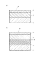
図1は、薄膜シート状の従来型の水素ガス検知用部材と、本実施形態の水素ガス検知用部材の構成の一例を示す概略断面図である。 FIG. 1 is a schematic cross-sectional view showing an example of the configuration of a conventional hydrogen gas detection member in the form of a thin film sheet and the hydrogen gas detection member of the present embodiment.
図1の(a)に示す薄膜シート状の水素ガス検知用部材(1A)は、従来型の水素ガス検知用部材であり、基板(2)上に、水素ガスを検知する酸化タングステン含有層(4)と触媒金属元素含有層(5)が積層されている構成であるが、このような構成の水素ガス検知用部材では、漏えいした水素ガス濃度に対する検知感度が低いという問題があった。 A thin-film sheet-shaped hydrogen gas detection member (1A) shown in FIG. 1 (a) is a conventional hydrogen gas detection member, and a tungsten oxide-containing layer (H2O) for detecting hydrogen gas on a substrate (2). 4) and the catalyst metal element-containing layer (5) are laminated, but the hydrogen gas detection member having such a configuration has a problem that the detection sensitivity to the leaked hydrogen gas concentration is low.
これに対し、図1の(b)に示す薄膜シート状の水素ガス検知用部材(1B)は、基板(2)上に、酸化タングステン含有層(4)のガスクロミック効果を増大させ、検知感度を高めるための酸化セリウム含有層(3)が配置され、その上に、水素ガスを検知する酸化タングステン含有層(4)と触媒金属元素含有層(5)が積層されている構成である。このような酸化セリウム含有層(3)を設ける構成の水素ガス検知用部材とすることにより、水素ガスを検知した際の酸化タングステン含有層(4)におけるHxWO3(淡黄色)からHyWO3(青色)への色相変化速度を増大させることができ、その結果、水素ガス濃度に対する検知感度を高めることができた。本実施形態の水素ガス検知用部材(1B)においては、上記のような効果を発現させるためには、酸化セリウム含有層(3)と酸化タングステン含有層(4)が隣接し、結晶粒界(Gb)を形成していることが特徴である。 On the other hand, the hydrogen gas detection member (1B) in the form of a thin film sheet shown in FIG. 1 (b) increases the gas chromic effect of the tungsten oxide-containing layer (4) on the substrate (2), thereby detecting sensitivity. A cerium oxide-containing layer (3) for increasing the temperature is disposed, and a tungsten oxide-containing layer (4) for detecting hydrogen gas and a catalytic metal element-containing layer (5) are laminated thereon. By using the hydrogen gas detection member configured to provide such a cerium oxide-containing layer (3), from the H x WO 3 (light yellow) to the H y in the tungsten oxide-containing layer (4) when hydrogen gas is detected. The hue change rate to WO 3 (blue) could be increased, and as a result, the detection sensitivity for the hydrogen gas concentration could be increased. In the hydrogen gas detection member (1B) of the present embodiment, in order to exhibit the above effects, the cerium oxide-containing layer (3) and the tungsten oxide-containing layer (4) are adjacent to each other, and the crystal grain boundary ( It is characteristic that Gb) is formed.
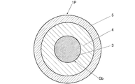
図2は、水素ガス検知用部材の構成の他の一例で、コア・シェル構造を有する粒子状の水素ガス検知用部材の概略断面図である。 FIG. 2 is a schematic cross-sectional view of a particulate hydrogen gas detection member having a core-shell structure as another example of the configuration of the hydrogen gas detection member.
図2に示す水素ガス検知用部材(1P)では、コア部に酸化セリウム含有層(3)を形成し、その表面部に、第1のシェル部として、酸化タングステン含有層(4)を被覆し、更にその表面部に、第2のシェル部として、触媒金属元素含有層(5)を担持させて、コア・シェル型構造の粒子を構成する。 In the hydrogen gas detection member (1P) shown in FIG. 2, a cerium oxide-containing layer (3) is formed on the core portion, and a tungsten oxide-containing layer (4) is coated on the surface portion as a first shell portion. Further, a catalyst metal element-containing layer (5) is supported on the surface portion as a second shell portion to constitute particles of a core / shell type structure.
図2示す水素ガス検知用部材(1P)においても、酸化セリウム含有層(3)と酸化タングステン含有層(4)とが隣接して配置され、結晶粒界(Gb)を形成していることが重要である。 Also in the hydrogen gas detection member (1P) shown in FIG. 2, the cerium oxide-containing layer (3) and the tungsten oxide-containing layer (4) are disposed adjacent to each other to form a crystal grain boundary (Gb). is important.
《水素ガス検知用部材の構成要素及び水素ガス検知用部材の製造方法》
水素ガス検知用部材の形態としては、特に制限はないが、上記図1の(b)で示したような薄膜シート状の水素ガス検知用部材、あるいは、図2で示したようなコア・シェル型構造を有する粒子状であることが好ましい。また、水素ガス検知用部材の製造方法は、以下に説明するように、酸化セリウム含有層と酸化タングステン層とを隣接して配置する工程と、酸化タングステン含有層の、酸化セリウム含有層に対向する面とは反対側に、触媒金属元素含有層を配置する工程とを含んでいる。
<< Components of Hydrogen Gas Detection Member and Manufacturing Method of Hydrogen Gas Detection Member >>
The form of the hydrogen gas detecting member is not particularly limited, but the thin film sheet-like hydrogen gas detecting member as shown in FIG. 1 (b) or the core / shell as shown in FIG. It is preferably in the form of particles having a mold structure. Moreover, the manufacturing method of the member for hydrogen gas detection faces the cerium oxide containing layer of the process of arrange | positioning a cerium oxide containing layer and a tungsten oxide layer adjacently, and a tungsten oxide containing layer so that it may demonstrate below. A step of disposing a catalytic metal element-containing layer on the side opposite to the surface.
以下、代表例として、薄膜シート状及びコア・シェル型構造を有する粒子状の水素ガス検知用部材について、その詳細を説明する。 Hereinafter, as a representative example, the details of a particulate hydrogen gas detection member having a thin film sheet shape and a core-shell structure will be described.
[薄膜シート状の水素ガス検知用部材]
薄膜シート状の水素ガス検知用部材は、図1の(b)で示すように、基板(2)上に、酸化セリウム含有層(3)、水素ガスを検知する酸化タングステン含有層(4)、及び触媒金属元素含有層(5)が、この順で積層された構成である。
[Thin-sheet hydrogen gas detection member]
As shown in FIG. 1B, the thin-film sheet-shaped hydrogen gas detection member has a cerium oxide-containing layer (3) on the substrate (2), a tungsten oxide-containing layer (4) for detecting hydrogen gas, And the catalyst metal element containing layer (5) is the structure laminated | stacked in this order.
〔基板〕
適用可能な基板としては、特に制限はない。
〔substrate〕
The applicable substrate is not particularly limited.
基板としては、上面に形成する酸化セリウム含有層(3)、酸化タングステン含有層(4)及び触媒金属元素含有層(5)を形成する環境、例えば、処理時の温度等に対する耐久性を有している基板であることが望ましく、このような基板としては、例えば、ポリエステル(例えば、ポリエチレンテレフタレート等)、ポリイミド、ポリメタクリル酸メチル、ポリスチレン、ポリプロピレン、ポリエチレン、ポリアミド、ナイロン、ポリ塩化ビニル、ポリ塩化ビニリデン、ポリカーボネート、ポリエーテルスルフォン、シリコン樹脂、ポリアセタール樹脂、フッ素樹脂、セルロース誘導体、ポリオレフィンなどの高分子のフィルムや板状基板、石英ガラス等のガラス基板などが好ましく用いられる。 The substrate has durability against the environment in which the cerium oxide-containing layer (3), tungsten oxide-containing layer (4) and catalytic metal element-containing layer (5) formed on the upper surface are formed, for example, the temperature during processing. It is desirable that the substrate is, for example, polyester (for example, polyethylene terephthalate), polyimide, polymethyl methacrylate, polystyrene, polypropylene, polyethylene, polyamide, nylon, polyvinyl chloride, polyvinyl chloride. A vinylidene, polycarbonate, polyether sulfone, silicon resin, polyacetal resin, fluororesin, cellulose derivative, polymer film such as polyolefin, a plate substrate, a glass substrate such as quartz glass, and the like are preferably used.
〔酸化セリウム含有層、酸化タングステン含有層及び触媒金属元素含有層の形成方法〕
本実施態様の水素ガス検知用部材において、酸化セリウム含有層と酸化タングステン含有層の厚さとしては、それぞれ25〜500nmの範囲内の薄膜であることが好ましい。特に、酸化タングステン含有層の厚さが25nm以上であれば、水素ガスに接触した際の透過率の変化や色相の変化を確実に検知することができる。また、それぞれの厚さが500nm以下であれば、酸化セリウム含有層及び酸化タングステン含有層の層間剥離の発生を防止することができる。
[Method of forming cerium oxide-containing layer, tungsten oxide-containing layer and catalytic metal element-containing layer]
In the hydrogen gas detection member of this embodiment, the thickness of the cerium oxide-containing layer and the tungsten oxide-containing layer is preferably a thin film in the range of 25 to 500 nm. In particular, when the thickness of the tungsten oxide-containing layer is 25 nm or more, it is possible to reliably detect a change in transmittance and a change in hue when contacted with hydrogen gas. Moreover, if each thickness is 500 nm or less, generation | occurrence | production of delamination of a cerium oxide content layer and a tungsten oxide content layer can be prevented.
また、堆積させる触媒金属元素含有層の厚さは1〜20nmの範囲内であることが好ましい。触媒金属元素含有層の厚さが20nm以下であれば、触媒自身による入射光の遮蔽を抑制することができ、透過光強度の変化の判別を阻害することがない。また、触媒金属元素含有層の厚さが1nm以上であれば、目視により容易に判別が可能な透過光強度の変化が得られ、水素ガスの検知が可能となる。 The thickness of the catalyst metal element-containing layer to be deposited is preferably in the range of 1 to 20 nm. If the thickness of the catalyst metal element-containing layer is 20 nm or less, the shielding of incident light by the catalyst itself can be suppressed, and determination of the change in transmitted light intensity is not hindered. Further, if the thickness of the catalytic metal element-containing layer is 1 nm or more, a change in transmitted light intensity that can be easily discriminated by visual observation can be obtained, and hydrogen gas can be detected.
水素ガス検知用部材において、酸化セリウム含有層、及び酸化タングステン含有層の形成方法としては、特に制限はなく、実施例は、スパッタリング法を用いたが、高周波スパッタリング法、直流スパッタリング法、真空蒸着法、電子ビーム蒸着法、化学気相蒸着法、パルスレーザーデポジション法(PLD法)、めっき法、ゾルゲル法等を採用してもかまわない。 In the hydrogen gas detection member, the formation method of the cerium oxide-containing layer and the tungsten oxide-containing layer is not particularly limited, and the examples used the sputtering method, but the high-frequency sputtering method, the direct current sputtering method, and the vacuum evaporation method. Electron beam vapor deposition, chemical vapor deposition, pulsed laser deposition (PLD), plating, sol-gel, etc. may be employed.
例えば、酸化セリウム含有層、酸化タングステン含有層及び触媒金属元素含有層の形成をスパッタリング法で行う場合には、酸化セリウム、タングステン、触媒金属をそれぞれスパッタリングターゲットとしてスパッタリングして、基板の表面上に、酸化セリウム薄膜、酸化タングステン薄膜を形成し、次いで、酸化タングステン薄膜の表面上に触媒金属を堆積することにより形成することができる。 For example, when the formation of the cerium oxide-containing layer, the tungsten oxide-containing layer, and the catalytic metal element-containing layer is performed by sputtering, cerium oxide, tungsten, and catalytic metal are sputtered as sputtering targets, respectively, on the surface of the substrate, It can be formed by forming a cerium oxide thin film or a tungsten oxide thin film and then depositing a catalytic metal on the surface of the tungsten oxide thin film.
スパッタリングはアルゴンと酸素の混合雰囲気であることが好ましい。スパッタリングを行う際の基板温度は、好ましくは室温(20℃)である。視覚的な色の変化により水素漏えいを検知することから、水素ガス検知用部材に求められる光吸収特性として、水素吸着により透過率が50%以上変化することが好ましい。該光吸収特性を達成するためには、例えば、投入スパッタリング電力が50W、基板とターゲットとの間の距離が10cmで、アルゴンと酸素の混合雰囲気でスパッタリングを行う場合、酸素ガス圧は14〜80mPa、アルゴンガス圧は130〜170mPaとすることが好ましい。更に好ましくは、酸素ガス圧は15〜40mPa、アルゴンガス圧は140〜160mPaである。スパッタリングをアルゴンと酸素の混合雰囲気で行う場合、水素吸着による透過率の変化が50%以上を達成するためには、厳密には他のスパッタリング条件にも依存するが、酸素ガスの比率は、全ガス圧(酸素ガス圧とアルゴンガス圧の和)の10〜30%の範囲内に制御すればよい。 Sputtering is preferably a mixed atmosphere of argon and oxygen. The substrate temperature at the time of sputtering is preferably room temperature (20 ° C.). Since hydrogen leakage is detected by a visual color change, it is preferable that the transmittance changes by 50% or more due to hydrogen adsorption as a light absorption characteristic required for a hydrogen gas detection member. In order to achieve the light absorption characteristics, for example, when the sputtering power is 50 W, the distance between the substrate and the target is 10 cm, and sputtering is performed in a mixed atmosphere of argon and oxygen, the oxygen gas pressure is 14 to 80 mPa. The argon gas pressure is preferably 130 to 170 mPa. More preferably, the oxygen gas pressure is 15 to 40 mPa and the argon gas pressure is 140 to 160 mPa. When sputtering is performed in a mixed atmosphere of argon and oxygen, in order to achieve a transmittance change of 50% or more due to hydrogen adsorption, strictly depending on other sputtering conditions, the ratio of oxygen gas is What is necessary is just to control within the range of 10-30% of gas pressure (the sum of oxygen gas pressure and argon gas pressure).
触媒金属の堆積は、パルスレーザーデポジション法、高周波スパッタリング法、直流スパッタリング法、分子線エピタキシー法、又は真空蒸着法により行うことができ、基板の耐熱温度以下にて堆積できるものであればいずれの方法でもよい。例えば、高周波スパッタリング法により触媒金属を堆積する場合は、堆積条件として、スパッタリング電力は25W〜50W、基板は室温で、アルゴンガス圧が130〜170mPaである雰囲気中で行うことが好ましい。 The catalyst metal can be deposited by a pulse laser deposition method, a high frequency sputtering method, a direct current sputtering method, a molecular beam epitaxy method, or a vacuum evaporation method, and any metal can be deposited at a temperature lower than the heat resistant temperature of the substrate. The method may be used. For example, when the catalytic metal is deposited by a high-frequency sputtering method, it is preferable to perform the deposition in an atmosphere in which the sputtering power is 25 W to 50 W, the substrate is at room temperature, and the argon gas pressure is 130 to 170 mPa.
触媒金属を形成する金属元素としては、貴金属元素(具体的には、白金、パラジウム、ロジウム、イリジウム、ルテニウム、及びオスミウム)、コバルト、ニッケル及び銅から選ばれる金属元素であることが好ましく、更には、白金、パラジウム、コバルト、ニッケル、又は銅を用いることが、より効果的に水素ガス検知を行うことができる観点から好ましい。これらのうち、複数種類の金属元素を用いてもよい。 The metal element forming the catalyst metal is preferably a metal element selected from noble metal elements (specifically, platinum, palladium, rhodium, iridium, ruthenium, and osmium), cobalt, nickel, and copper, It is preferable to use platinum, palladium, cobalt, nickel, or copper from the viewpoint that hydrogen gas can be detected more effectively. Of these, a plurality of types of metal elements may be used.
なお、薄膜シート状の水素ガス検知用部材の形成方法の詳細については、特開2005−345338号公報、特開2007−71866号公報、特開2007−155436号公報、特開2007−278744号公報等に記載されている内容を参考にすることができる。 The details of the method for forming the thin-film sheet-shaped hydrogen gas detection member are disclosed in JP-A-2005-345338, JP-A-2007-71866, JP-A-2007-155436, and JP-A-2007-278744. Etc. can be referred to.
[コア・シェル構造粒子状の水素ガス検知用部材]
コア・シェル構造を有する粒子状の水素ガス検知用部材の調製方法としては、水溶液環境下で、順次粒子成長を行い、コア・シェル構造を有する粒子を形成する方法が好ましい。
[Particulate hydrogen gas detection member with core / shell structure]
As a method for preparing a particulate hydrogen gas detection member having a core / shell structure, a method in which particles are sequentially grown in an aqueous solution environment to form particles having a core / shell structure is preferable.
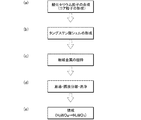
具体的には、図3及び図4に記載の製造工程フローに従って、調製することができる。 Specifically, it can be prepared according to the manufacturing process flow described in FIGS.
主要な製造工程としては、図3に示すように、酸化セリウムを含有するコア粒子を形成し、コア粒子上に酸化タングステンを含有する第1のシェル部を形成し、第1のシェル部上に触媒金属元素を含む第2のシェル部を形成する工程を備えている。詳しくは、
(a)硝酸セリウム、硝酸、アンモニア等を用いて、水溶液中で酸化セリウムの微結晶の晶出及び成長を行い、酸化セリウムから構成されるコア粒子(コア部)を形成する工程、
(b)上記調製した酸化セリウムのコア粒子を含有する懸濁液を用いて、タングステン酸ナトリウム及び硝酸等を用いて、コア粒子表面にタングステン酸(H2WO4)から構成される第1のシェル部を形成する工程。
As shown in FIG. 3, the main manufacturing process is to form core particles containing cerium oxide, to form a first shell portion containing tungsten oxide on the core particles, and on the first shell portion. Forming a second shell portion containing the catalytic metal element. For more information,
(A) crystallization and growth of cerium oxide microcrystals in an aqueous solution using cerium nitrate, nitric acid, ammonia, etc., and forming core particles (core part) composed of cerium oxide;
(B) A first suspension composed of tungstic acid (H 2 WO 4 ) on the surface of the core particle using sodium tungstate, nitric acid or the like using the suspension containing the cerium oxide core particles prepared above. Forming a shell portion;
(c)上記調製した酸化セリウム/タングステン酸(H2WO4)から構成されるコア・シェル粒子を含む懸濁液に、触媒金属塩を含む水溶液を添加して、コア・シェル粒子表面に、金属触媒を堆積、担持させて、第2のシェル部として、触媒金属元素含有層を形成する工程、
(d)以上により調製したコア・シェル粒子を含む懸濁液(粒子分散液)を、濃縮、固液分離、及び洗浄を行い、不要の塩類等を除去した後、乾燥する。
(C) An aqueous solution containing a catalyst metal salt is added to a suspension containing core / shell particles composed of cerium oxide / tungstic acid (H 2 WO 4 ) prepared above, A step of depositing and supporting a metal catalyst to form a catalyst metal element-containing layer as a second shell portion;
(D) The suspension (particle dispersion) containing the core / shell particles prepared as described above is concentrated, solid-liquid separated, and washed to remove unnecessary salts and the like, and then dried.
(e)最後に、焼成処理を行って、タングステン酸(H2WO4)を酸化タングステン(HxWO3)に酸化して、薄黄緑色のコア・シェル粒子状の水素ガス検知用部材を調製する。 (E) Finally, a baking treatment is performed to oxidize tungstic acid (H 2 WO 4 ) to tungsten oxide (H x WO 3 ), thereby producing a light yellow green core / shell particle hydrogen gas detection member. Prepare.
次いで、コア・シェル粒子状の水素ガス検知用部材の調製方法について説明する。 Next, a method for preparing a core / shell particle hydrogen gas detection member will be described.
(コア粒子の調製)
第1段階は、セリウム(III)塩の溶液である開始溶液を調製する。セリウム(III)塩として、例えば、硝酸セリウム(III)、塩化セリウム(III)、硫酸セリウム(III)、炭酸セリウム(III)及びこれらの塩の混合物(硝酸塩/塩化物の混合物等)を使用することができるが、硝酸セリウム(III)を用いることが好ましい。
(Preparation of core particles)
The first stage prepares an initial solution that is a solution of a cerium (III) salt. As the cerium (III) salt, for example, cerium (III) nitrate, cerium (III) chloride, cerium (III) sulfate, cerium carbonate (III) and a mixture of these salts (such as a nitrate / chloride mixture) are used. Although it is possible to use cerium (III) nitrate.
以下、セリウム(III)塩の代表例として、硝酸セリウムを用いる方法について説明する。 Hereinafter, a method using cerium nitrate will be described as a representative example of the cerium (III) salt.
硝酸セリウムを含む開始溶液は、セリウムが溶液中において安定した状態で存在させるため酸性度を調整することが好ましく、例えば、硝酸を用いて、開始溶液である混合液のpHを制御する。 The acidity of the starting solution containing cerium nitrate is preferably adjusted because cerium is present in a stable state in the solution. For example, nitric acid is used to control the pH of the mixed solution that is the starting solution.
この第1段階で調製した混合液は、不活性ガスを通気することにより、事前に脱ガス処理を施すことができる。不活性ガスとしては、例えば、窒素ガスやアルゴンガスを適用することができる。 The mixed solution prepared in the first stage can be degassed in advance by passing an inert gas. As the inert gas, for example, nitrogen gas or argon gas can be applied.
次いで、の第2段階では、混合溶液と塩基水溶液とを反応させる。塩基水溶液としては、アルカリ金属又はアルカリ土類金属水酸化物、及びアンモニア水を挙げることができる。また、第2級アミン、第3級アミン又は第4級アミンも使用でき得る。上記の中でも、アミン又はアンモニア水が好ましい。これは、アミン及びアンモニア水を用いることにより、アルカリ金属カチオン又はアルカリ土類金属カチオンによる汚染のリスクが軽減される。この塩基溶液(例えば、アンモニア水)に、上記調製した混合溶液を撹拌しながら添加する。この時も、不活性ガスを用いて通気することにより、脱ガス処理することができる。 Next, in the second stage, the mixed solution and the base aqueous solution are reacted. Examples of the aqueous base solution include alkali metal or alkaline earth metal hydroxide, and aqueous ammonia. Secondary amines, tertiary amines or quaternary amines can also be used. Among the above, amine or aqueous ammonia is preferable. This reduces the risk of contamination with alkali metal cations or alkaline earth metal cations by using amines and aqueous ammonia. The mixed solution prepared above is added to this base solution (for example, aqueous ammonia) with stirring. Also at this time, degassing can be performed by aeration using an inert gas.
上記の第2段階は、閉鎖反応装置又は半閉鎖反応装置のいずれかにおいて、不活性ガスによるスイープを行いながら、不活性雰囲気下で行うことが好ましい。接触は、一般に、攪拌反応装置内で行われる。 The second stage is preferably performed in an inert atmosphere while sweeping with an inert gas in either a closed reactor or a semi-closed reactor. Contact is generally carried out in a stirred reactor.
この第2段階は、一般に、周囲温度(20〜25℃)又は最高50℃の温度にて行われる。 This second stage is generally performed at ambient temperature (20-25 ° C.) or temperatures up to 50 ° C.
第3段階は、上記調製した酸化セリウム懸濁液に対し熱処理を行う。この熱処理は、おおむね60〜95℃の範囲で温度を維持しながら、1〜5時間程度の熱処理を行う。
この処理の継続時間は、数分から数時間になり得る。また、この熱処理も、不活性雰囲気下で行われる。
In the third stage, the prepared cerium oxide suspension is heat-treated. This heat treatment is performed for about 1 to 5 hours while maintaining the temperature in the range of about 60 to 95 ° C.
The duration of this process can be from a few minutes to a few hours. This heat treatment is also performed in an inert atmosphere.
最後の段階で、酸性化処理及び洗浄処理を行う。 In the last stage, acidification treatment and washing treatment are performed.
酸性化は、一般に、第3段階の最後で得られた懸濁液を冷却した後に、酸の添加によって行われる。酸としては無機酸又は有機酸のいずれも使用することができるが、硝酸を用いることが好ましい。添加される酸の量は、酸性化後の懸濁液のpHが2〜4の範囲内となる条件で添加する。この作業は、通常の大気環境下で行うことができる。 Acidification is generally carried out by addition of acid after cooling the suspension obtained at the end of the third stage. As the acid, either an inorganic acid or an organic acid can be used, but nitric acid is preferably used. The amount of the acid added is such that the pH of the suspension after acidification is in the range of 2 to 4. This operation can be performed in a normal atmospheric environment.
酸性化に続いて、洗浄が行われる。その目的は、懸濁液から可溶性種、原則的に塩を除去することにあり、固体/液体を分離して又は分離することなく、様々なやり方で行うことができる。 Following acidification, washing is performed. Its purpose is to remove soluble species, in principle salts, from the suspension, which can be carried out in various ways, with or without separating the solid / liquid.
(タングステン酸シェルの形成)
第1段階としては、上記調製した酸化セリウムにより構成されるコア粒子を含む懸濁液に対し、タングステン酸塩を含む水溶液を添加して、懸濁液を調製する。
(Formation of tungstic acid shell)
As a first step, an aqueous solution containing tungstate is added to a suspension containing core particles composed of the prepared cerium oxide to prepare a suspension.
次いで、酸化セリウムコア粒子とタングステン酸塩を含む懸濁液に、酸を添加する。この時、使用する酸としては、無機酸又は有機酸のいずれも使用することができるが、硝酸を用いることが好ましい。添加される酸の量は、酸性化後の懸濁液のpHが1以下となる条件で添加する。酸の添加は、室温下で撹拌しながら20〜60分かけてゆっくり添加し、酸化セリウムコア粒子の表面に、タングステン酸(H2WO4)の第1のシェル層を形成する。 Next, an acid is added to the suspension containing the cerium oxide core particles and the tungstate. At this time, as the acid to be used, either an inorganic acid or an organic acid can be used, but nitric acid is preferably used. The amount of acid added is such that the pH of the suspension after acidification is 1 or less. The acid is slowly added over 20 to 60 minutes with stirring at room temperature to form a first shell layer of tungstic acid (H 2 WO 4 ) on the surface of the cerium oxide core particles.
次いで、遠心分離による粒子の沈降、デカンテーションによる上澄み液の排液、洗浄用の純水の添加の工程を4〜10回程度繰り返して行い、不要な塩類の除去を行い、コア層が酸化セリウムで、第1のシェル層がタングステン酸(H2WO4)より構成されるコア・シェル粒子Aを含む懸濁液を調製する。 Next, the steps of sedimentation of the particles by centrifugation, draining of the supernatant liquid by decantation, and addition of pure water for washing are repeated about 4 to 10 times to remove unnecessary salts, and the core layer is made of cerium oxide. Then, a suspension containing the core-shell particles A in which the first shell layer is composed of tungstic acid (H 2 WO 4 ) is prepared.
(触媒金属元素層の形成)
次いで、上記酸化セリウム/タングステン酸(H2WO4)より構成されるコア・シェル粒子Aを含む懸濁液に対し、触媒金属元素を含む化合物、例えば、H2PtCl6/6H2O、PdCl2、Co(NO3)2、Ni(NO3)2、Cu(NO3)2等を含む水溶液を、ゆっくりと添加し、この状態を3〜10時間維持させて、タングステン酸(H2WO3)層表面に、触媒金属元素を担持させた第2のシェル層を形成して、コア層が酸化セリウムで、第1のシェル層がタングステン酸(H2WO4)、第2のシェル層が触媒金属元素により構成されるコア・シェル粒子Bを含む懸濁液を調製する。
(Formation of catalytic metal element layer)
Next, a compound containing a catalytic metal element, such as H 2 PtCl 6 / 6H 2 O, PdCl, is added to the suspension containing the core-shell particles A composed of the cerium oxide / tungstic acid (H 2 WO 4 ). 2 , an aqueous solution containing Co (NO 3 ) 2 , Ni (NO 3 ) 2 , Cu (NO 3 ) 2, etc. is slowly added, and this state is maintained for 3 to 10 hours to obtain tungstic acid (H 2 WO 3 ) A second shell layer supporting a catalytic metal element is formed on the surface of the layer, the core layer is cerium oxide, the first shell layer is tungstic acid (H 2 WO 4 ), and the second shell layer A suspension containing the core-shell particles B composed of a catalytic metal element is prepared.
(焼成処理によるタングステン酸(H2WO4)の酸化タングステン(HxWO3)への変換)
上記調製したコア・シェル粒子Bを含む懸濁液を、エバポレーター等を用いて水分を除いた後、得られたコア・シェル粒子Bを80〜150℃で、1〜5時間乾燥させた後、150〜400℃の温度範囲で、30分〜3時間の焼成処理を施すことにより、タングステン酸(H2WO4)層を、酸化タングステン(HxWO3)層に変化させることにより、コア・シェル構造の水素ガス検知用部材を得ることができる。
(Conversion of tungstic acid (H 2 WO 4 ) to tungsten oxide (H x WO 3 ) by firing treatment)
After removing the water containing the prepared core / shell particles B using an evaporator or the like, and drying the obtained core / shell particles B at 80 to 150 ° C. for 1 to 5 hours, By subjecting the tungstic acid (H 2 WO 4 ) layer to a tungsten oxide (H x WO 3 ) layer by performing a baking process for 30 minutes to 3 hours in a temperature range of 150 to 400 ° C. A member for detecting a hydrogen gas having a shell structure can be obtained.
このコア・シェル構造の水素ガス検知用部材では、前述のように、無色の酸化タングステン(HxWO3)が水素ガスと反応し、酸化タングステン(HyWO3)に変化することにより、青色への色相変化や透過率の変化を検知することにより、水素ガスを検知する。 In the hydrogen gas detecting member having the core-shell structure, as described above, the colorless tungsten oxide (H x WO 3 ) reacts with the hydrogen gas and changes to tungsten oxide (H y WO 3 ), thereby changing the blue color. Hydrogen gas is detected by detecting changes in hue and transmittance.
コアを構成する酸化セリウム粒子の直径としては、50〜200nmの範囲内であり、酸化タングステン層の厚さは、25〜100nmの範囲内であり、触媒金属元素層の厚さは、1〜20nmの範囲内とすることが好ましい。 The diameter of the cerium oxide particles constituting the core is in the range of 50 to 200 nm, the thickness of the tungsten oxide layer is in the range of 25 to 100 nm, and the thickness of the catalytic metal element layer is 1 to 20 nm. It is preferable to be within the range.
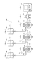
次いで、図4を用いて、コア・シェル粒子状の水素ガス検知用粒子の具体的な製造例について説明する。 Next, a specific production example of core / shell particles for detecting hydrogen gas will be described with reference to FIG.
図4は、コア・シェル粒子状の水素ガス検知用粒子の製造工程の具体的なフローを示す図である。 FIG. 4 is a diagram showing a specific flow of a manufacturing process of core / shell particles of hydrogen gas detection particles.
(酸化セリウム含有層より構成するコア粒子の形成:工程a及び工程a1)
はじめに、図4に記載の反応釜(101)を有する工程a及び添加剤の調製釜(105)を有する工程a1を用いて、酸化セリウムより構成されるコア粒子を調製する。
(Formation of core particles composed of a cerium oxide-containing layer: step a and step a1)
First, core particles composed of cerium oxide are prepared using the step a having the reaction vessel (101) shown in FIG. 4 and the step a1 having the additive preparation vessel (105).
例えば、工程a1の調製釜(105)に、硝酸セリウム水溶液と硝酸水溶液を添加し、攪拌機(107)で撹拌しながら混合液(106)を調製し、N2ガスで通気しながら、撹拌する。 For example, an aqueous cerium nitrate solution and an aqueous nitric acid solution are added to the preparation kettle (105) of step a1, and a mixed solution (106) is prepared while stirring with a stirrer (107), and stirred while being aerated with N 2 gas.
一方、反応釜(101)に、母液(102)としてアンモニア水溶液を添加し、N2ガスで通気しながら、攪拌機(103)で撹拌する。 On the other hand, an aqueous ammonia solution is added as a mother liquor (102) to the reaction vessel (101), and the mixture is stirred with a stirrer (103) while being aerated with N 2 gas.
次いで、反応釜(101)のアンモニア水溶液中に、送液ポンプ(110)を用いて、調製釜(105)より硝酸セリウム水溶液と硝酸水溶液の混合液(106)を、N2ガス雰囲気下で撹拌しながら添加して、懸濁液を調製する。 Next, the mixed solution (106) of the cerium nitrate aqueous solution and the nitric acid aqueous solution is stirred from the preparation kettle (105) into the aqueous ammonia solution in the reaction kettle (101) under an N 2 gas atmosphere using the feed pump (110). To make a suspension.
次いで、N2ガスを通気撹拌しながら、懸濁液を60〜90℃程度まで昇温し、その状態を一定時間維持する。 Next, the temperature of the suspension is raised to about 60 to 90 ° C. while agitating and stirring N 2 gas, and this state is maintained for a certain time.
次いで、懸濁液を室温程度まで降温した後、硝酸を添加してpHを2.0まで下げたのち、N2ガスの通気を停止して、酸化セリウム粒子(コア粒子)を含む懸濁液(104)を調製する。 Next, after the temperature of the suspension is lowered to about room temperature, nitric acid is added to lower the pH to 2.0, and then the aeration of N 2 gas is stopped, and the suspension contains cerium oxide particles (core particles). (104) is prepared.
(タングステン酸によるシェル部の形成:工程b及び工程b1)
次いで、図4に記載の反応釜(111)を有する工程b及び添加剤調製釜(115)を有する工程b1を用いて、工程aで調製した酸化セリウムより構成されるコア粒子表面に、シェル層としてタングステン酸を被覆して、コア・シェル型粒子を調製する。
(Formation of shell portion with tungstic acid: step b and step b1)
Next, a shell layer is formed on the surface of the core particles composed of cerium oxide prepared in step a using step b having the reaction vessel (111) and step b1 having an additive preparation vessel (115) shown in FIG. The core-shell type particles are prepared by coating with tungstic acid.
はじめに、調製釜(115)に、タングステン酸ナトリウム水溶液(116)を準備する。また、他方の調製釜(115)には、硝酸水溶液(116)を準備する。 First, an aqueous sodium tungstate solution (116) is prepared in a preparation kettle (115). In the other preparation kettle (115), an aqueous nitric acid solution (116) is prepared.
反応釜(111)に上記調製した酸化セリウム粒子(コア粒子)を含む懸濁液(104)を母液として貯留し、当該懸濁液(104)を撹拌しながら、調製釜(115)よりタングステン酸ナトリウム水溶液を添加する。 The suspension (104) containing the cerium oxide particles (core particles) prepared above is stored as a mother liquor in the reaction kettle (111), and the tungstic acid is stirred from the preparation kettle (115) while stirring the suspension (104). Add aqueous sodium solution.
次いで、同懸濁液(104)に他方の調製釜(115)より硝酸水溶液を添加してpHを1.0程度まで低下させ、この状態で一定時間維持して、酸化セリウム(CeO2)がコア粒子で、その表面にタングステン酸(H2WO4)のシェルを形成したコア・シェル粒子を含む懸濁液(112、CeO2/H2WO4懸濁液)を調製する。 Next, an aqueous nitric acid solution is added to the suspension (104) from the other preparation kettle (115) to lower the pH to about 1.0, and this state is maintained for a certain period of time, so that cerium oxide (CeO 2 ) A suspension (112, CeO 2 / H 2 WO 4 suspension) containing core-shell particles in which a shell of tungstic acid (H 2 WO 4 ) is formed on the surface of the core particles is prepared.
(最表面に触媒金属元素含有層の形成:工程c及び工程c1)
次いで、図4に記載の反応釜(121)を有する工程c及び調製釜(125)を有する工程c1を用いて、上記調製したコア・シェル型粒子の表面に触媒金属元素含有層を担持させて、最終的なコア・シェル型粒子を調製する。
(Formation of catalytic metal element-containing layer on outermost surface: step c and step c1)
Next, using the step c having the reaction kettle (121) and the step c1 having the preparation kettle (125) shown in FIG. The final core-shell type particles are prepared.
調製釜(125)に、例えば、触媒金属元素含有化合物としてH2PtCl6・6H2O水溶液を準備する。 Preparation kettle (125), for example, to prepare a H 2 PtCl 6 · 6H 2 O aqueous solution as a catalyst metal element-containing compound.
一方、反応釜(121)に、上記調製したCeO2/H2WO4懸濁液(112)を準備する。 On the other hand, the prepared CeO 2 / H 2 WO 4 suspension (112) is prepared in the reaction kettle (121).
次いで、反応釜(121)のCeO2/H2WO4懸濁液(111)に、送液ポンプ(128)を用いて、調製釜(125)よりH2PtCl6・6H2O水溶液(126)を、撹拌しながら、所定時間を要して添加し、タングステン酸(H2WO4)層上に触媒として白金を含む触媒金属元素含有層を担持したCeO2/H2WO4/Pt懸濁液(127)を調製する。
Then, the CeO 2 /
コア・シェル型粒子においても、触媒金属を形成する金属元素としては、白金、パラジウム、ロジウム、イリジウム、ルテニウム、オスミウム、コバルト、ニッケル及び銅から選ばれる金属元素であることが好ましく、更には、白金、パラジウム、コバルト、ニッケル、又は銅を用いることが、より効果的に水素ガス検知を行うことができる観点から好ましい。これらのうち、複数種類の金属元素を用いてもよい。 Also in the core-shell type particles, the metal element that forms the catalyst metal is preferably a metal element selected from platinum, palladium, rhodium, iridium, ruthenium, osmium, cobalt, nickel, and copper. It is preferable to use palladium, cobalt, nickel, or copper from the viewpoint that hydrogen gas can be detected more effectively. Of these, a plurality of types of metal elements may be used.
(乾燥及び焼成処理)
上記調製したCeO2/H2WO4/Pt懸濁液(127)を、濾過・洗浄工程(工程d)で、遠心分離、デカンデーション法による上澄み液の排液、純水の添加の操作を繰り返して、洗浄処理を行う。
(Drying and baking treatment)
The CeO 2 / H 2 WO 4 / Pt suspension (127) prepared above is subjected to the operations of centrifugation, draining the supernatant liquid by decantation method, and adding pure water in the filtration and washing step (step d). Repeat the cleaning process.
次いで、焼成工程(工程e)で水分を除いた紛体を、焼成装置(141)を用いて加熱乾燥した後、150〜400℃の温度範囲で焼成処理を施して、H2WO4をHxWO3に変換して、CeO2/HxWO3/Ptから構成されるコア・シェル型粒子である水素ガス検知用部材を調製する。ここで、xは0.5以上、0.8未満の数値を取る。 Next, the powder from which moisture has been removed in the firing step (step e) is heat-dried using a firing device (141), and then subjected to a firing treatment in a temperature range of 150 to 400 ° C., thereby converting H 2 WO 4 into H x. converted to WO 3, to prepare a hydrogen gas detecting member is a core-shell particles composed of CeO 2 / H x WO 3 / Pt. Here, x takes a numerical value of 0.5 or more and less than 0.8.
《水素ガス検知システムの基本構成》
図5に、水素ガス検知用部材を用いた水素ガス検知システムの基本構成の一例を示す。
<Basic configuration of hydrogen gas detection system>
FIG. 5 shows an example of a basic configuration of a hydrogen gas detection system using a hydrogen gas detection member.
図5の(a)に示した水素ガス検知測定装置(50)は、光透過型の水素ガス検知用部材(1)を用いた際の水素ガス検知システムの一例を示すものであり、中央に、光透過性の基板(2)、酸化セリウム含有層(3)、酸化タングステン含有層(4)及び触媒金属元素含有層(5)から構成される水素ガス検知用部材(1)を配置し、左側に光源部(51)を配置し、右側には、水素ガス検知用部材(1)を通過してきた光量(透過光)を測定する分光光度計(52)を配置する。この時、分光光度計(52)による測定波長としては、酸化タングステン含有層の変化の検出に感度の高い600nmの波長の光を用いることが好ましい。 The hydrogen gas detection measuring device (50) shown in FIG. 5 (a) shows an example of a hydrogen gas detection system when using a light transmission type hydrogen gas detection member (1). A hydrogen gas detection member (1) composed of a light-transmitting substrate (2), a cerium oxide-containing layer (3), a tungsten oxide-containing layer (4) and a catalytic metal element-containing layer (5), A light source unit (51) is arranged on the left side, and a spectrophotometer (52) for measuring the amount of light (transmitted light) that has passed through the hydrogen gas detection member (1) is arranged on the right side. At this time, as the wavelength measured by the spectrophotometer (52), it is preferable to use light having a wavelength of 600 nm, which is highly sensitive for detecting changes in the tungsten oxide-containing layer.
はじめに、基準として、水素ガスを除去した空気をガス流入口(54)より水素ガス検知測定装置(50)内に流入させ、ガス流出口(55)より流出させながら、光源部(51)より、可視光線(L)を照射し、波長600nmの光における空気雰囲気下での光透過率TP1(全照射光に対する光透過光の比率(%))を測定する。 First, as a reference, air from which hydrogen gas has been removed flows from the gas inlet (54) into the hydrogen gas detection and measurement device (50), and flows out from the gas outlet (55). Visible light (L) is irradiated, and light transmittance TP1 (ratio of light transmitted light to total irradiated light (%)) in an air atmosphere with light having a wavelength of 600 nm is measured.
次いで、水素ガス検知測定装置(50)内に流入するガスを、1体積%の水素ガスを含む空気に変更して、同様に1体積%水素ガスに暴露した時の波長600nmの光における光透過率TP2を測定し、下式(1)に従い、水素ガス濃度に対する各水素ガス検知用部材の光透過率変化(%)を測定し、これを水素ガス検知用部材の水素ガス検知能の尺度として求める。 Next, the gas flowing into the hydrogen gas detection / measurement device (50) is changed to air containing 1% by volume hydrogen gas, and similarly, light is transmitted through light having a wavelength of 600 nm when exposed to 1% by volume hydrogen gas. The rate TP2 is measured, and the change in light transmittance (%) of each hydrogen gas detection member with respect to the hydrogen gas concentration is measured according to the following formula (1), and this is used as a measure of the hydrogen gas detection ability of the hydrogen gas detection member. Ask.
式(1)
光透過率変化(%)=TP2/TP1×100
図5の(b)で示した水素ガス検知測定装置(50)は、上記図5の(a)で示した構成とは異なり、反射型の水素ガス検知用部材(1)を用いた際の水素ガス検知システムの一例を示すものであり、基材(2a)が光不透過性の材料で構成され、反射光を分光光度計(52)で測定して求める方法である。
Formula (1)
Light transmittance change (%) = TP2 / TP1 × 100
Unlike the configuration shown in FIG. 5 (a), the hydrogen gas detection / measurement device (50) shown in FIG. 5 (b) uses a reflective hydrogen gas detection member (1). This shows an example of a hydrogen gas detection system, in which the base material (2a) is made of a light-impermeable material and the reflected light is measured by a spectrophotometer (52).
《水素ガス検知システム》
図6に、水素ガス検知用部材を用いた水素ガス検知システムの一例を示す。
《Hydrogen gas detection system》
FIG. 6 shows an example of a hydrogen gas detection system using a hydrogen gas detection member.
図6に示すように、水素ガスを使用している機器、例えば、水素ガスボンベ(C)や水素ガスタンク(D)が配置されている環境下で、水素ガス検知用部材は有効に使用することができる。 As shown in FIG. 6, the hydrogen gas detection member can be used effectively in an environment where hydrogen gas is used, for example, in an environment where a hydrogen gas cylinder (C) and a hydrogen gas tank (D) are arranged. it can.
水素ガス検知用部材が薄膜シート状の形態であれば、室内の壁面(B)や、水素ガスボンベ(C)表面、水素ガスタンク(D)表面の一部又は全面に貼り付けて配置することができる。 If the member for detecting hydrogen gas is in the form of a thin film sheet, it can be disposed on the wall surface (B) of the room, the surface of the hydrogen gas cylinder (C), the surface of the hydrogen gas tank (D) or the entire surface. .
また、本発明の水素ガス検知用部材がコア・シェル型粒子の形態であれば、バインダーに分散させて塗料として調製した後、室内の天井(A)や壁面(B)、水素ガスボンベ(C)や水素ガスタンク(D)の外壁、水素ガスタンク(D)の配管(E)、バルブ(F)、ポンプ(G)等に塗装して設けることができる。 Further, if the hydrogen gas detection member of the present invention is in the form of core / shell type particles, it is dispersed in a binder and prepared as a paint, and then the indoor ceiling (A), wall surface (B), hydrogen gas cylinder (C). Or the outer wall of the hydrogen gas tank (D), the pipe (E), the valve (F), the pump (G), etc. of the hydrogen gas tank (D).
本実施形態の水素ガス検知システムは、水素ガス容器設置室(61)に設置された水素ガス検知用部材の光透過率や色相の変化を検知するための光学測定装置(62)と、光学測定装置で入手した色相変化を監視する検知装置(63)と、警報装置(64)と、バルブ(F)やポンプ(G)を制御するための水素ガス供給制御部(65)と、を備えている。本システムは、各所に設置した水素ガス検知用部材が検知した水素ガスの漏えいを、光学測定装置(62)及び検知装置(63)によって検知する。具体的には、光学測定装置(62)を用いて反射光を受光することにより、水素ガス検知用部材の色相の変化を測定し、検知装置(63)によって、反射光の色調や反射光量が事前に規定している閾値(規定値)を外れた場合に、水素ガスの漏えいが発生したと判定する。警報装置(63)が漏えいありと判定した場合、検知装置(63)から送信される情報に基づいて、警報手段(64)が警報を発するとともに、水素ガス漏れの発生源であるバルブ(F)の遮断やポンプ(G)の駆動を停止させる制御信号(66)を、ガス供給制御部(65)より送信する。 The hydrogen gas detection system of the present embodiment includes an optical measurement device (62) for detecting a change in light transmittance and hue of a hydrogen gas detection member installed in the hydrogen gas container installation chamber (61), and an optical measurement. A detection device (63) for monitoring the hue change obtained by the device, an alarm device (64), and a hydrogen gas supply control unit (65) for controlling the valve (F) and the pump (G). Yes. In this system, leakage of hydrogen gas detected by hydrogen gas detection members installed in various places is detected by the optical measurement device (62) and the detection device (63). Specifically, the change in the hue of the hydrogen gas detection member is measured by receiving the reflected light using the optical measurement device (62), and the color tone and the amount of reflected light of the reflected light are measured by the detection device (63). When the threshold value (specified value) specified in advance is deviated, it is determined that the leakage of hydrogen gas has occurred. When the alarm device (63) determines that there is a leak, the alarm means (64) issues an alarm based on the information transmitted from the detection device (63), and the valve (F) that is the source of hydrogen gas leakage The gas supply control unit (65) transmits a control signal (66) for shutting off the power supply and stopping the pump (G).
以下、本発明の具体的な実施例について説明するが、本発明はこれらに限定されるものではない。なお、実施例において「部」又は「%」の表示が用いられるが、特に断りが無い限り「質量部」又は「質量%」を表す。なお、以下の説明で、各構成要素の後に括弧で表示している数字は、関連する図に表示している各構成部材の番号を示してある。 Hereinafter, specific examples of the present invention will be described, but the present invention is not limited thereto. In addition, although the display of "part" or "%" is used in an Example, unless there is particular notice, it represents "mass part" or "mass%". In the following description, the number displayed in parentheses after each component indicates the number of each component displayed in the related figure.
実施例1
《薄膜シート状の水素ガス検知用部材の作製》
以下の方法に従って、薄膜シート状の水素ガス検知用部材1〜6を作製した。
Example 1
<< Production of thin-film sheet-like hydrogen gas detection member >>
In accordance with the following method, the hydrogen
〔水素ガス検知用部材1の作製〕
下記の方法に従って、図1の(b)に相当する構成を有する薄膜シート状の水素ガス検知用部材1(1S)を作製した。
[Production of hydrogen gas detection member 1]
In accordance with the following method, a hydrogen gas detection member 1 (1S) in the form of a thin film sheet having a configuration corresponding to FIG.
(基板(2)の準備)
基板(2)として、10mm×10mm、厚さ1mmの石英基板を用いた。
(Preparation of substrate (2))
A quartz substrate having a size of 10 mm × 10 mm and a thickness of 1 mm was used as the substrate (2).
(酸化セリウム含有層の形成)
ターゲットとして酸化セリウム(CeO2)を用い、スパッタリングにより、上記基板上に、層厚が100nmの酸化セリウム含有層(3)を堆積させて形成した。
(Formation of cerium oxide-containing layer)
Using cerium oxide (CeO 2 ) as a target, a cerium oxide-containing layer (3) having a layer thickness of 100 nm was deposited on the substrate by sputtering.
スパッタリングは、Arガス分圧を120mPa、酸素ガス分圧を50mPaとし、室温(25℃)下、50Wの電力で、層厚100nmとなるように酸化セリウム(CeO2)をDCパルススパッタした。ターゲット−基板間距離は、100mmであった。 Sputtering was performed by DC pulse sputtering of cerium oxide (CeO 2 ) with an Ar gas partial pressure of 120 mPa and an oxygen gas partial pressure of 50 mPa, with a power of 50 W at room temperature (25 ° C.) to a layer thickness of 100 nm. The target-substrate distance was 100 mm.
(酸化タングステン含有層の形成)
次いで、上記形成した酸化セリウム含有層(3)上に、上記と同様のスパッタリングにより、ターゲットとして金属タングステン(W)を用い、層厚が100nmの酸化タングステン含有層(4、HxWO3)を堆積した。Arガス分圧を130mPa、酸素ガス分圧を30mPaで行った。
(Formation of a tungsten oxide-containing layer)
Next, a tungsten oxide-containing layer (4, H x WO 3 ) having a layer thickness of 100 nm is formed on the formed cerium oxide-containing layer (3) by sputtering similar to the above using metal tungsten (W) as a target. Deposited. Ar gas partial pressure was 130 mPa and oxygen gas partial pressure was 30 mPa.
(触媒金属元素含有層の形成)
次いで、上記形成した酸化タングステン含有層(4)上に、上記と同様のスパッタリングにより、ターゲットとして白金(Pt)を用い、層厚が10nmのPtから構成される触媒金属元素含有層(5)を堆積して、水素ガス検知用部材1を作製した。Arガス分圧を170mPaで行った。
(Formation of catalyst metal element-containing layer)
Next, a catalytic metal element-containing layer (5) composed of Pt having a layer thickness of 10 nm is formed on the tungsten oxide-containing layer (4) thus formed by sputtering similar to the above using platinum (Pt) as a target. The hydrogen
〔水素ガス検知用部材2及び3の作製〕
上記水素ガス検知用部材1の作製において、触媒金属元素含有層の形成金属を、白金(Pt)に代えて、それぞれパラジウム(Pd)、コバルト(Co)を用いた以外は同様にして、水素ガス検知用部材2及び3を作製した。
[Production of hydrogen
In the production of the hydrogen
〔水素ガス検知用部材4〜6の作製〕
上記水素ガス検知用部材1〜3の作製において、酸化セリウム含有層(3)の形成を除いた以外は同様にして、水素ガス検知用部材4〜6を作製した。
[Preparation of hydrogen
In the production of the hydrogen
《水素ガス検知用部材の評価》
下記の方法に従って、各水素ガス検知用部材の水素ガス検知能の評価を行った。
《Evaluation of hydrogen gas detection member》
According to the following method, the hydrogen gas detection ability of each hydrogen gas detection member was evaluated.
図5に記載の水素ガス検知測定装置(50)を用いて、光透過率変化(%)を測定した。 The change in light transmittance (%) was measured using the hydrogen gas detection measuring device (50) shown in FIG.
図5に記載の水素ガス検知測定装置(50)内に、上記作製した各水素ガス検知用部材(1)を、光源部(51)側が基板(2)面となるように設置、固定した。 In the hydrogen gas detection measuring apparatus (50) shown in FIG. 5, each of the produced hydrogen gas detection members (1) was installed and fixed so that the light source part (51) side was the substrate (2) surface.
はじめに、空気をガス流入口(54)より水素ガス検知測定装置(50)内に流入させ、ガス流出口(55)より流出させながら、光源部(51)より、可視光線(L)を照射し、波長600nmの光における空気雰囲気下での光透過率TP1(全照射光に対する光透過光の比率(%))を、分光光度計(52)で測定した。 First, visible light (L) is irradiated from the light source part (51) while flowing air into the hydrogen gas detection measuring device (50) from the gas inlet (54) and out of the gas outlet (55). The light transmittance TP1 (the ratio (%) of light transmitted light to the total irradiated light) in an air atmosphere with light having a wavelength of 600 nm was measured with a spectrophotometer (52).
次いで、水素ガス検知測定装置(50)内に流入するガスを、1体積%の水素ガスを含む空気に変更させた以外は同様にして、1体積%水素ガスに暴露した時の波長600nmの光における光透過率TP2を、同じく分光光度計(52)で測定し、上述した式(1)に従い、水素ガス濃度に対する各水素ガス検知用部材の光透過率変化(%)を測定し、これを水素ガス検知能の尺度とした。 Next, light having a wavelength of 600 nm when exposed to 1% by volume hydrogen gas in the same manner except that the gas flowing into the hydrogen gas detection / measurement device (50) is changed to air containing 1% by volume hydrogen gas. The light transmittance TP2 is measured with the spectrophotometer (52), and the change in light transmittance (%) of each hydrogen gas detecting member with respect to the hydrogen gas concentration is measured according to the above-described equation (1). A measure of hydrogen gas detection ability.
以上により得られた結果を、表1に示す。 The results obtained as described above are shown in Table 1.
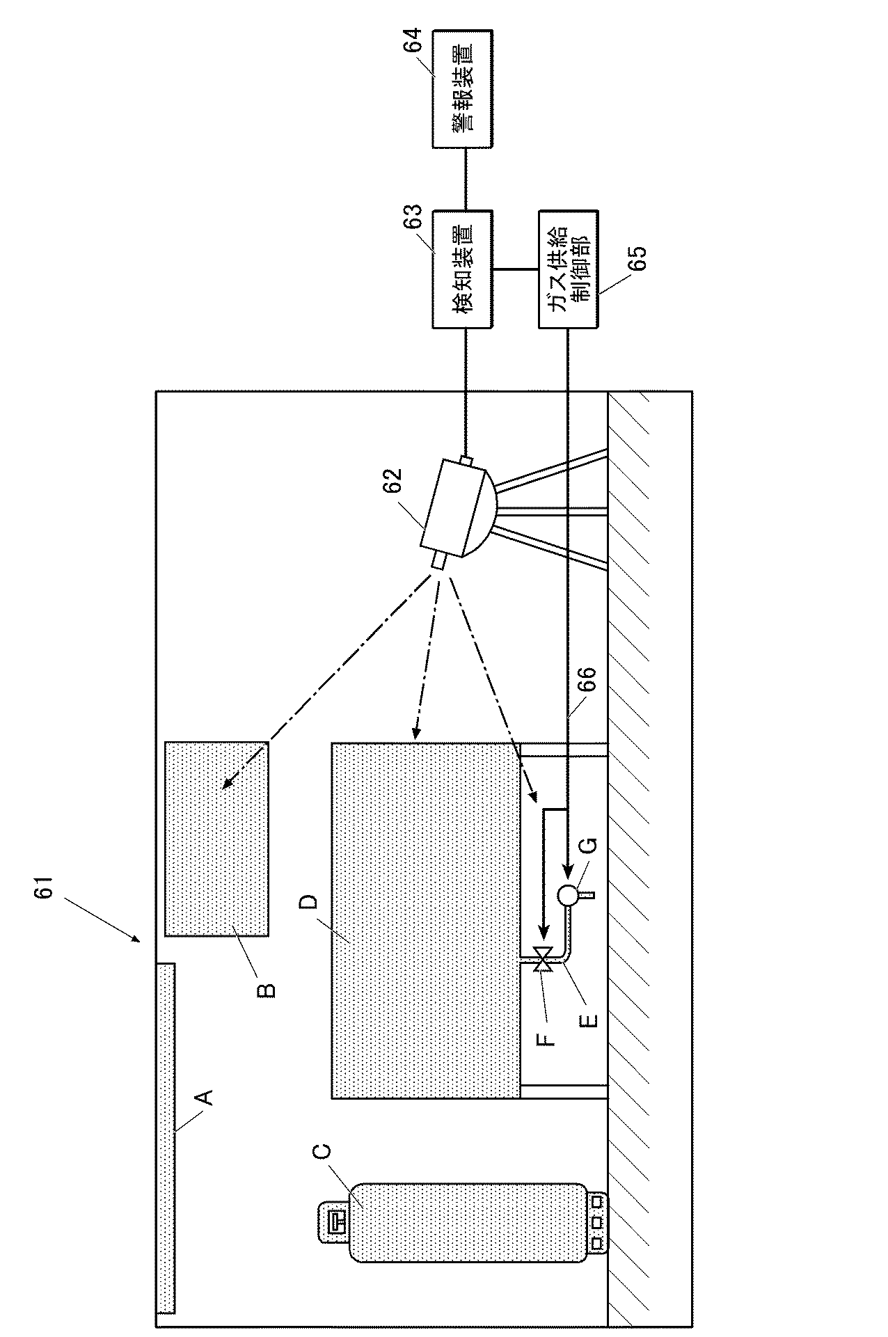
表1に記載の結果より明らかなように、酸化セリウム含有層を酸化タングステン含有層の下に設け、酸化セリウムと酸化タングステンが接触する構成とした水素ガス検知用部材は、比較例に対し、水素ガスに曝された際の色変化、具体的には、淡い黄緑色の酸化タングステン(HxWO3)から濃い青色(タングステンブロンズ)の酸化タングステン(HyWO3)への変化に伴う可視光領域における光透過率の低下が大きく、水素ガスの検知感度が高いことが分かる。同一の触媒種で比較すると、Pt系では、水素ガス検知用部材4が40%であるのに対し、水素ガス検知用部材1は19%まで低下し、同様に、Pd系では、水素ガス検知用部材5が39%であるのに対し、水素ガス検知用部材2は21%まで低下し、Co系では、水素ガス検知用部材6が65%であるのに対し、水素ガス検知用部材3は37%まで低下し、いずれの触媒系においても、酸化セリウム含有層を設けることにより、水素ガス検知能が大きく向上していることが分かる。
As is clear from the results shown in Table 1, the hydrogen gas detection member in which the cerium oxide-containing layer is provided under the tungsten oxide-containing layer and the cerium oxide and tungsten oxide are in contact with each other has a hydrogen Color change upon exposure to gas, specifically visible light associated with a change from light yellow-green tungsten oxide (H x WO 3 ) to dark blue (tungsten bronze) tungsten oxide (H y WO 3 ) It can be seen that the decrease in light transmittance in the region is large, and the hydrogen gas detection sensitivity is high. When compared with the same catalyst type, the hydrogen
実施例2
《コア・シェル型粒子の水素ガス検知用部材の作製》
以下の方法に従って、コア・シェル型粒子の水素ガス検知用部材11〜15を作製した。
Example 2
《Preparation of core / shell particle hydrogen gas detection member》
In accordance with the following method, the core-shell type particle hydrogen gas detection members 11 to 15 were produced.
〔水素ガス検知用部材11の作製〕
図4に記載のコア・シェル粒子の製造工程フロー(100)に従って、コア・シェル型粒子より構成される水素ガス検知用部材11を作製した。なお、反応釜及び調整釜の符号と工程名は、図4に記載したもに対応している。
[Production of Hydrogen Gas Detection Member 11]
In accordance with the core / shell particle manufacturing process flow (100) shown in FIG. 4, a hydrogen gas detection member 11 composed of core / shell type particles was produced. In addition, the code | symbol and process name of a reaction kettle and an adjustment kettle respond | correspond to what was described in FIG.
(酸化セリウム含有層より構成するコア粒子の形成)
はじめに、反応釜(101)を用いる工程a及び添加剤の調製釜(105)を用いる工程a1に従って、酸化セリウムより構成されるコア粒子を調製した。
(Formation of core particles composed of a cerium oxide-containing layer)
First, core particles composed of cerium oxide were prepared according to step a using the reaction vessel (101) and step a1 using the additive preparation vessel (105).
具体的には、まず、工程a1の調製釜(105)に、0.4モル/Lの硝酸セリウム水溶液の50mLと、0.4モル/Lの硝酸水溶液の50mLとを添加し、攪拌機(107)で撹拌しながら混合液(106)を調製し、N2ガスで通気しながら、2時間撹拌した。 Specifically, first, 50 mL of 0.4 mol / L cerium nitrate aqueous solution and 50 mL of 0.4 mol / L nitric acid aqueous solution were added to the preparation kettle (105) of step a1, and a stirrer (107 ) To prepare a liquid mixture (106) while stirring, and stirred for 2 hours while venting with N 2 gas.
一方、反応釜(101)に、母液(102)として、0.5モル/Lのアンモニア水溶液の300mLを添加し、N2ガスで通気しながら、攪拌機(103)で2時間撹拌した。 On the other hand, 300 mL of a 0.5 mol / L aqueous ammonia solution was added to the reaction kettle (101) as a mother liquor (102), and the mixture was stirred with a stirrer (103) for 2 hours while venting with N 2 gas.
次いで、反応釜(101)のアンモニア水溶液中に、送液ポンプ(110)を用いて、調製釜(105)より硝酸セリウム水溶液と硝酸セリウム水溶液の混合液(106)を、N2ガス雰囲気下で撹拌しながら、25分かけて、4mL/minの添加速度で添加して、懸濁液を調製した。 Next, the mixed solution (106) of the cerium nitrate aqueous solution and the cerium nitrate aqueous solution is transferred from the preparation kettle (105) into the aqueous ammonia solution in the reaction kettle (101) under an N 2 gas atmosphere. A suspension was prepared by adding at a rate of 4 mL / min over 25 minutes while stirring.
次いで、N2ガスを通気撹拌しながら、懸濁液を80℃まで昇温し、その状態を3時間維持した。 Next, the suspension was heated to 80 ° C. while agitating and stirring N 2 gas, and this state was maintained for 3 hours.
次いで、懸濁液を25℃まで降温した後、0.4モル/Lの硝酸を添加してpHを2.0まで下げたのち、N2ガスの通気を停止して、平均粒子径が50nmの酸化セリウム粒子(コア粒子)を含む懸濁液(104)を調製した。 Next, the temperature of the suspension was lowered to 25 ° C., 0.4 mol / L nitric acid was added to lower the pH to 2.0, and then the N 2 gas aeration was stopped, and the average particle size was 50 nm. A suspension (104) containing cerium oxide particles (core particles) was prepared.
(タングステン酸によるシェル部の形成)
次いで、反応釜(111)を用いる工程b及び添加剤用の2つの調製釜(115A及び115B)を用いる工程b1に従って、上記調製した酸化セリウムより構成されるコア粒子表面に、シェル層としてタングステン酸を被覆して、コア・シェル型粒子を調製した。
(Formation of shell by tungstic acid)
Next, tungstic acid is formed as a shell layer on the surface of the core particles composed of cerium oxide prepared in accordance with step b using the reaction vessel (111) and step b1 using two preparation vessels for additives (115A and 115B). Were coated to prepare core-shell type particles.
具体的には、まず、調製釜(115A)に、3.2モル/Lのタングステン酸ナトリウム水溶液(116A)50mLを準備した。また、他方の調製釜(115B)には、3モル/Lの硝酸水溶液(116B)を25mL準備した。 Specifically, first, 50 mL of a 3.2 mol / L sodium tungstate aqueous solution (116A) was prepared in a preparation kettle (115A). In the other preparation kettle (115B), 25 mL of 3 mol / L nitric acid aqueous solution (116B) was prepared.
反応釜(111)に上記調製した酸化セリウム粒子(コア粒子)を含む懸濁液(104)を母液として貯留し、当該懸濁液(104)を撹拌しながら、調製釜(115A)よりタングステン酸ナトリウム水溶液(116A)を添加した。 The suspension (104) containing the prepared cerium oxide particles (core particles) is stored as a mother liquor in the reaction kettle (111), and the suspension (104) is stirred and the tungstic acid is added from the preparation kettle (115A). Aqueous sodium solution (116A) was added.
次いで、同懸濁液(104)に調製釜(115B)より硝酸水溶液(116B)を、25分かけて添加し、pHを1.0まで下げて、この状態で、25分で30分間撹拌して、酸化セリウム(CeO2)がコア粒子で、その表面にタングステン酸(H2WO4)のシェルを形成した平均粒子径が110nmの粒子を含む懸濁液(112、CeO2/H2WO4懸濁液)を調製した。 Next, an aqueous nitric acid solution (116B) was added to the suspension (104) from the preparation kettle (115B) over 25 minutes, the pH was lowered to 1.0, and in this state, the mixture was stirred for 25 minutes for 30 minutes. Then, a suspension (112, CeO 2 / H 2 WO) containing particles having an average particle diameter of 110 nm in which cerium oxide (CeO 2 ) is a core particle and a shell of tungstic acid (H 2 WO 4 ) is formed on the surface thereof. 4 suspension) was prepared.
次いで懸濁液を、遠心分離、デカンデーション法による上澄み液の排液、純水の添加の操作を5回繰り返して、洗浄処理を行った。 Subsequently, the suspension was subjected to washing treatment by repeating the operations of centrifugation, draining the supernatant liquid by decantation method, and adding pure water five times.
次いで、洗浄済みの懸濁液(112)に純水を添加し、5質量%に仕上げた。 Subsequently, pure water was added to the washed suspension (112) to finish to 5% by mass.
(最表面に触媒金属元素含有層の形成)
次いで、反応釜(121)を用いる工程c及び調製釜(125)を用いる工程c1に従って、上記調製したコア・シェル型粒子の表面に触媒金属元素含有層を担持させて、コア・シェル型粒子を調製した。
(Formation of catalytic metal element-containing layer on the outermost surface)
Next, according to the step c using the reaction kettle (121) and the step c1 using the preparation kettle (125), a catalyst metal element-containing layer is supported on the surface of the prepared core-shell type particles, and the core-shell type particles are obtained. Prepared.
調製釜(125)に、100ミリモル/LのH2PtCl6・6H2O水溶液(126)の300mLを準備した。 Preparation kettle (125), was prepared 300mL of 100 mmol / L H 2 PtCl 6 · 6H 2 O solution (126).
一方、反応釜(121)に、上記調製した5質量%のCeO2/H2WO4懸濁液(112)を準備した。
On the other hand, to the reaction vessel (121) was prepared CeO 2 /
次いで、反応釜(121)の5質量%のCeO2/H2WO4懸濁液(112)に、送液ポンプ(128)を用いて、調製釜(125)より300mLのH2PtCl6・6H2O水溶液(126)を、撹拌しながら、30分かけて添加し、H2WO4層上に触媒として白金を含む触媒金属元素含有層を厚さ2nmで担持し、CeO2/H2WO4/Pt懸濁液(127)を5時間撹拌して調製した。 Next, 300 mL of H 2 PtCl 6 · from the preparation kettle (125) was added to the 5 mass% CeO 2 / H 2 WO 4 suspension (112) of the reaction kettle (121) using the liquid feed pump (128). A 6H 2 O aqueous solution (126) was added with stirring over 30 minutes, and a catalytic metal element-containing layer containing platinum as a catalyst was supported on the H 2 WO 4 layer at a thickness of 2 nm. CeO 2 / H 2 A WO 4 / Pt suspension (127) was prepared by stirring for 5 hours.
(乾燥及び焼成処理)
上記調製したCeO2/H2WO4/Pt懸濁液(127)を、エバポレーターで水を蒸発させた。
(Drying and baking treatment)
Water was evaporated from the prepared CeO 2 / H 2 WO 4 / Pt suspension (127) using an evaporator.
次いで、水分を除いた紛体を、100℃で3時間乾燥させた後、200℃で1時間の焼成処理を施して、CeO2/HxWO3/Ptから構成される平均粒子径が112nmのコア・シェル型粒子である水素ガス検知用部材11を調製した。 Next, the powder from which moisture was removed was dried at 100 ° C. for 3 hours, and then subjected to a firing treatment at 200 ° C. for 1 hour to obtain an average particle diameter of 112 nm composed of CeO 2 / H x WO 3 / Pt. A hydrogen gas detection member 11 that is a core-shell type particle was prepared.
〔水素ガス検知用部材12の作製〕
上記水素ガス検知用部材11の作製の最表面に触媒金属元素含有層の形成において、触媒材料として、100ミリモル/LのH2PtCl6・6H2O水溶液に代えて、100ミリモル/LのPdCl2水溶液に変更した以外は同様にして、水素ガス検知用部材12を作製した。
[Production of Hydrogen Gas Detection Member 12]
In the formation of the catalytic metal element-containing layer on the outermost surface of the production of the hydrogen gas detecting member 11, as a catalyst material, in place of the H 2 PtCl 6 · 6H 2 O aqueous solution of 100 mmol / L, PdCl of 100 mmol / L A hydrogen gas detection member 12 was produced in the same manner except that the aqueous solution was changed to 2 aqueous solution.
〔水素ガス検知用部材13の作製〕
上記水素ガス検知用部材11の作製の最表面に触媒金属元素含有層の形成において、触媒材料として、100ミリモル/LのH2PtCl6・6H2O水溶液に代えて、100ミリモル/LのCo(NO3)2水溶液に変更した以外は同様にして、水素ガス検知用部材13を作製した。
[Production of Hydrogen Gas Detection Member 13]
In the formation of the catalytic metal element-containing layer on the outermost surface of the production of the hydrogen gas detecting member 11, as a catalyst material, in place of the H 2 PtCl 6 · 6H 2 O aqueous solution of 100 mmol / L, 100 mmol / L Co A hydrogen gas detecting member 13 was produced in the same manner except that the aqueous solution was changed to (NO 3 ) 2 aqueous solution.
〔水素ガス検知用部材14の作製〕
上記水素ガス検知用部材11の作製の最表面に触媒金属元素含有層の形成において、触媒材料として、100ミリモル/LのH2PtCl6・6H2O水溶液に代えて、100ミリモル/LのNi(NO3)2水溶液に変更した以外は同様にして、水素ガス検知用部材14を作製した。
[Production of Hydrogen Gas Detection Member 14]
In the formation of the catalytic metal element-containing layer on the outermost surface of the production of the hydrogen gas detection member 11, the catalyst material is replaced with 100 mmol / L Ni aqueous solution instead of 100 mmol / L H 2 PtCl 6 .6H 2 O aqueous solution. A hydrogen gas detection member 14 was produced in the same manner except that the aqueous solution was changed to (NO 3 ) 2 aqueous solution.
〔水素ガス検知用部材15の作製〕
上記水素ガス検知用部材11の作製の最表面に触媒金属元素含有層の形成において、触媒材料として、100ミリモル/LのH2PtCl6・6H2O水溶液に代えて、100ミリモル/LのCu(NO3)2水溶液に変更した以外は同様にして、水素ガス検知用部材15を作製した。
[Production of Hydrogen Gas Detection Member 15]
In the formation of the catalytic metal element-containing layer on the outermost surface of the production of the hydrogen gas detecting member 11, as a catalyst material, in place of the H 2 PtCl 6 · 6H 2 O aqueous solution of 100 mmol / L, 100 mmol / L Cu A hydrogen gas detection member 15 was produced in the same manner except that the solution was changed to (NO 3 ) 2 aqueous solution.
《コア・シェル型粒子の水素ガス検知用部材の評価》
上記作製した粉末状のコア・シェル型粒子の水素ガス検知用部材を、1体積%の水素ガスを含む空気雰囲気下に暴露した結果、全ての粒子が、速やかに薄黄緑色から濃青色(タングステンブロンズ)に色相変化を生じ、水素ガス検知感度が極めて高いことを確認することができた。
<< Evaluation of core / shell type particles for detecting hydrogen gas >>
As a result of exposing the above-prepared powder core-shell particle hydrogen gas detection member to an air atmosphere containing 1% by volume of hydrogen gas, all the particles were rapidly changed from light yellow green to dark blue (tungsten). Bronze) showed a hue change, and it was confirmed that the hydrogen gas detection sensitivity was extremely high.
実施例3
図6に記載したのと同様の構成を備える水素ガス容器設置室を用いて、水素ガス漏えいに対する水素ガス検知用部材による水素ガス検知効果を実証した。
Example 3
Using a hydrogen gas container installation chamber having a configuration similar to that described in FIG. 6, the hydrogen gas detection effect of the hydrogen gas detection member against hydrogen gas leakage was demonstrated.
図6に示したのと同様に、水素ガス容器設置室内に、水素ガス源として、水素ガスボンベ及び水素ガスタンクを配置した。 In the same manner as shown in FIG. 6, a hydrogen gas cylinder and a hydrogen gas tank were arranged as a hydrogen gas source in the hydrogen gas container installation chamber.
そして、実施例1で作製した薄膜シート状の水素ガス検知用部材を、試験室の壁面、水素ガスボンベ表面、水素ガスタンク表面に貼り付けて設置した(それぞれ、図6の(B)、(C)、(D)に相当する。)
また、実施例2で作製したコア・シェル型粒子の水素ガス検知用部材については、バインダーを分散させて塗料とした後、水素ガス容器設置室内部の天井、水素ガスタンクの配管、バルブ、ポンプに塗装した(それぞれ、図6の(A)、(E)、(F)に相当する。)。さらに、試験室内に、水素ガス検知用部材の色相変化を測定するための光学測定装置と、光学測定装置で入手した色相変化を監視する検知装置、光学測定装置で測定した水素ガスの漏えいによる水素ガス検知用部材の色相の変化幅が、事前に規定している閾値を超えた場合に警報を発する警報装置と、水素ガス漏れの発生源であるバルブの遮断やポンプの駆動を停止させる制御信号を送信する水素ガス供給制御部を備える水素ガス検知システムを設置した。
Then, the thin-film sheet-shaped hydrogen gas detection member produced in Example 1 was attached to the wall surface of the test chamber, the hydrogen gas cylinder surface, and the hydrogen gas tank surface (respectively, (B) and (C) in FIG. 6). , (D).)
In addition, for the core / shell type hydrogen gas detection member produced in Example 2, after the binder is dispersed to form a paint, it is applied to the ceiling inside the hydrogen gas container installation chamber, the piping of the hydrogen gas tank, the valve, and the pump. Painted (corresponding to (A), (E), and (F) in FIG. 6, respectively). Furthermore, in the test chamber, an optical measurement device for measuring the hue change of the hydrogen gas detection member, a detection device for monitoring the hue change obtained by the optical measurement device, and hydrogen due to leakage of hydrogen gas measured by the optical measurement device An alarm device that issues an alarm when the hue change range of the gas detection member exceeds a predefined threshold, and a control signal that shuts off the valve that is the source of hydrogen gas leakage and stops the pump drive A hydrogen gas detection system equipped with a hydrogen gas supply control unit that transmits
上記水素ガス検知システムにより、試験室内に、1体積%の水素ガスを含む空気雰囲気を流入させて、各水素ガス検知用部材の色相変化を観察した結果、全ての水素ガス検知用部材が速やかに薄黄緑色から濃青色(タングステンブロンズ)に色相変化と光透過率の低下を生じ、この光透過率変化や色相変化を光学測定手段である光学測定装置で検知し、瞬時にバルブの遮断やポンプの駆動停止を行うことができた。 As a result of observing the hue change of each hydrogen gas detection member by flowing an air atmosphere containing 1% by volume of hydrogen gas into the test chamber by the hydrogen gas detection system, all the hydrogen gas detection members were quickly Hue changes from light yellow green to dark blue (tungsten bronze) and light transmittance decreases, and this light transmittance change and hue change are detected by an optical measuring device that is an optical measuring means, and the valve is shut off or pumped instantaneously. It was possible to stop driving.
1A、1B、1P 水素ガス検知用部材
2、2a 基板
3 酸化セリウム含有層
4 酸化タングステン含有層
5 触媒金属元素含有層
50 水素ガス検知測定装置
51 光源部
52 分光光度計
54 ガス流入口
55 ガス流出口
61 水素ガス容器設置室
62 光学測定装置
63 検知装置
64 警報装置
65 水素ガス供給制御部
66 制御信号
100 コア・シェル粒子の製造工程
101、111、121 反応釜
102 母液
103、107 撹拌機
104、112、127 懸濁液
105、115、125 調製釜
106 混合液
108 送液ポンプ
131 濾過・洗浄装置
141 焼成装置
A 天井
B 壁面
C 水素ガスボンベ
D 水素ガスタンク
E 配管
F バルブ
G ポンプ
Gb 結晶粒界
L 可視光線
1A, 1B, 1P Hydrogen
Claims (10)
前記酸化セリウム含有層と前記酸化タングステン含有層とが隣接して配置され、前記触媒金属元素含有層が、前記酸化タングステン含有層の、前記酸化セリウム含有層に対向する面とは反対側に配置され、
水素ガス濃度変化に応じて、光吸収特性が変化することを特徴とする水素ガス検知用部材。 A cerium oxide-containing layer, a tungsten oxide-containing layer, and a catalytic metal element-containing layer,
The cerium oxide-containing layer and the tungsten oxide-containing layer are disposed adjacent to each other, and the catalytic metal element-containing layer is disposed on the opposite side of the surface of the tungsten oxide-containing layer that faces the cerium oxide-containing layer. ,
A member for detecting hydrogen gas, wherein light absorption characteristics change according to a change in hydrogen gas concentration.
酸化セリウム含有層と酸化タングステン含有層とを隣接して配置し、
前記酸化タングステン含有層の、前記酸化セリウム含有層に対向する面とは反対側に、
触媒金属元素含有層を配置する、
ことを特徴とする水素ガス検知用部材の製造方法。 A method for producing a hydrogen gas detection member for producing the hydrogen gas detection member according to any one of claims 1 to 4,
A cerium oxide-containing layer and a tungsten oxide-containing layer are disposed adjacent to each other;
On the opposite side of the tungsten oxide-containing layer from the surface facing the cerium oxide-containing layer,
Arranging a catalytic metal element-containing layer,
A method for producing a hydrogen gas detection member.
酸化セリウムを含有するコア粒子を形成し、
前記コア粒子上に、酸化タングステンを含有する第1のシェル部を形成し、
前記第1のシェル部上に触媒金属元素を含む第2のシェル部を形成する、
ことを特徴とする水素ガス検知用部材の製造方法。 A method for producing a hydrogen gas detection member for producing the hydrogen gas detection member according to claim 5 or 6,
Forming core particles containing cerium oxide,
Forming a first shell portion containing tungsten oxide on the core particles;
Forming a second shell portion containing a catalytic metal element on the first shell portion;
A method for producing a hydrogen gas detection member.
当該水素ガス検知用部材に特定の波長を照射する光源部と、
前記水素ガス検知用部材を通過した光を測定する光学測定装置と、
前記光学測定装置で測定した光吸収特性が規定値を超えるか否かを検知する検知装置と、
前記検知装置が検知する情報に基づき警報を発する警報装置と、
を備えることを特徴とする水素ガス検知システム。 The hydrogen gas detection member according to any one of claims 1 to 6,
A light source unit for irradiating the hydrogen gas detection member with a specific wavelength;
An optical measuring device for measuring the light passing through the hydrogen gas detecting member;
A detection device for detecting whether or not the light absorption characteristic measured by the optical measurement device exceeds a specified value;
An alarm device that issues an alarm based on information detected by the detection device; and
A hydrogen gas detection system comprising:
Priority Applications (2)
| Application Number | Priority Date | Filing Date | Title |
|---|---|---|---|
| JP2015044499A JP2018071969A (en) | 2015-03-06 | 2015-03-06 | Hydrogen gas detection component, its manufacturing method, and hydrogen gas detection system |
| PCT/JP2016/051200 WO2016143385A1 (en) | 2015-03-06 | 2016-01-18 | Hydrogen gas detecting member, method for manufacturing same, and hydrogen gas detecting system |
Applications Claiming Priority (1)
| Application Number | Priority Date | Filing Date | Title |
|---|---|---|---|
| JP2015044499A JP2018071969A (en) | 2015-03-06 | 2015-03-06 | Hydrogen gas detection component, its manufacturing method, and hydrogen gas detection system |
Publications (1)
| Publication Number | Publication Date |
|---|---|
| JP2018071969A true JP2018071969A (en) | 2018-05-10 |
Family
ID=56880326
Family Applications (1)
| Application Number | Title | Priority Date | Filing Date |
|---|---|---|---|
| JP2015044499A Pending JP2018071969A (en) | 2015-03-06 | 2015-03-06 | Hydrogen gas detection component, its manufacturing method, and hydrogen gas detection system |
Country Status (2)
| Country | Link |
|---|---|
| JP (1) | JP2018071969A (en) |
| WO (1) | WO2016143385A1 (en) |
Cited By (1)
| Publication number | Priority date | Publication date | Assignee | Title |
|---|---|---|---|---|
| JP2024526873A (en) * | 2021-08-19 | 2024-07-19 | 中国石油化工股▲ふん▼有限公司 | Hydrogen gas leak detection material, its manufacturing method and use |
Family Cites Families (6)
| Publication number | Priority date | Publication date | Assignee | Title |
|---|---|---|---|---|
| JPH1010039A (en) * | 1996-06-24 | 1998-01-16 | Dkk Corp | Beam splitter and absorbance measuring device using the beam splitter |
| JP2007057233A (en) * | 2005-08-22 | 2007-03-08 | Hitachi Cable Ltd | Optical gas sensor |
| US9011778B2 (en) * | 2006-10-12 | 2015-04-21 | Nextech Materials, Ltd. | Hydrogen sensitive composite material, hydrogen gas sensor, and sensor for detecting hydrogen and other gases with improved baseline resistance |
| US8048384B1 (en) * | 2010-08-31 | 2011-11-01 | University Of Central Florida Research Foundation, Inc. | Chemochromic hydrogen sensors |
| EP3021640A4 (en) * | 2013-07-09 | 2017-03-29 | Nitto Denko Corporation | Organic electroluminescent device, and refrigerator |
| JP3192325U (en) * | 2014-05-28 | 2014-08-07 | 功 村上 | Optical hydrogen gas detection switch |
-
2015
- 2015-03-06 JP JP2015044499A patent/JP2018071969A/en active Pending
-
2016
- 2016-01-18 WO PCT/JP2016/051200 patent/WO2016143385A1/en not_active Ceased
Cited By (2)
| Publication number | Priority date | Publication date | Assignee | Title |
|---|---|---|---|---|
| JP2024526873A (en) * | 2021-08-19 | 2024-07-19 | 中国石油化工股▲ふん▼有限公司 | Hydrogen gas leak detection material, its manufacturing method and use |
| JP7703771B2 (en) | 2021-08-19 | 2025-07-07 | 中国石油化工股▲ふん▼有限公司 | Hydrogen gas leak detection material, its manufacturing method and use |
Also Published As
| Publication number | Publication date |
|---|---|
| WO2016143385A1 (en) | 2016-09-15 |
Similar Documents
| Publication | Publication Date | Title |
|---|---|---|
| US10921302B2 (en) | Method for manufacturing chemochromic nanoparticles | |
| Piccirillo et al. | Synthesis and functional properties of vanadium oxides: V2O3, VO2, and V2O5 deposited on glass by aerosol‐assisted CVD | |
| Eom et al. | Strong localized surface plasmon resonance effects of Ag/TiO 2 core–shell nanowire arrays in UV and visible light for photocatalytic activity | |
| US8052898B2 (en) | Hydrogen gas detecting material and the coating method | |
| US8268392B1 (en) | Visual hydrogen detector with variable reversibilty | |
| Giusto et al. | Colorimetric detection of perfluorinated compounds by all-polymer photonic transducers | |
| KR102242201B1 (en) | Hydrogen sensor and method of manufacturing the hydrogen sensor | |
| Juine et al. | Recyclable ZnS QDs as an efficient photocatalyst for dye degradation under the UV and visible light | |
| Jaballah et al. | Effect of Al and Mg Co-doping on the microstructural and gas-sensing characteristics of ZnO nanoparticles | |
| JP2016075661A (en) | Hydrogen detection coloring sensor | |
| JP2008286542A (en) | Hydrogen gas detection membrane | |
| Sáenz-Trevizo et al. | Efficient and durable ZnO core-shell structures for photocatalytic applications in aqueous media | |
| JP2018071969A (en) | Hydrogen gas detection component, its manufacturing method, and hydrogen gas detection system | |
| Saxena et al. | Metal oxide nanocomposites for gas and VOC sensors based on other optical methods | |
| Warwick et al. | Multifunctional nanocomposite thin films by aerosol‐assisted CVD | |
| Zhu et al. | Self-Assembled ZnO QDs@ ZIF-8 Fillers for Low-Cost Bronze Artifacts Corrosion Monitoring | |
| US20200264102A1 (en) | Nanostructure array, hydrogen detection element, and hydrogen detection device | |
| JP4900954B2 (en) | Hydrogen sensor using magnesium-niobium alloy thin film | |
| Fang et al. | High selectivity and fluorescence reversible Eu3+ sensor based on GSH-capped AgZnInS QDs | |
| Danish et al. | Influence of thickness and calcination under ammonia gas flow on topographical, optical and photocatalytic properties of Nb2O5 thin films prepared by sol–gel: a comparative study | |
| Horváth et al. | Interaction of poly (vinyl alcohol) with the Belousov–Zhabotinsky reaction mixture | |
| El Fidha et al. | Boosting photocatalytic efficiency through Ni–Co co-doped ZnO thin films fabricated by spray pyrolysis | |
| Lova | Flory-Huggins Photonic Sensors | |
| Domínguez-Flores et al. | Efficient photodecoloration catalysts, based on ZnO nanoparticles coated in two steps on glass substrates | |
| Al-Zanganawee et al. | Impact of Addition of ZnO and CuO Colloidal Nanoparticles on the Physical Properties of the NiO Nanostructured Thin Film for Gas Sensing |