JP2018057504A - Structure of side-rail - Google Patents
Structure of side-rail Download PDFInfo
- Publication number
- JP2018057504A JP2018057504A JP2016195825A JP2016195825A JP2018057504A JP 2018057504 A JP2018057504 A JP 2018057504A JP 2016195825 A JP2016195825 A JP 2016195825A JP 2016195825 A JP2016195825 A JP 2016195825A JP 2018057504 A JP2018057504 A JP 2018057504A
- Authority
- JP
- Japan
- Prior art keywords
- side rail
- foot
- bed
- rail
- head
- Prior art date
- Legal status (The legal status is an assumption and is not a legal conclusion. Google has not performed a legal analysis and makes no representation as to the accuracy of the status listed.)
- Pending
Links
- 230000007246 mechanism Effects 0.000 claims abstract description 85
- 230000003028 elevating effect Effects 0.000 claims abstract description 16
- 238000010586 diagram Methods 0.000 description 7
- 230000004048 modification Effects 0.000 description 3
- 238000012986 modification Methods 0.000 description 3
- 230000000474 nursing effect Effects 0.000 description 3
- 238000000034 method Methods 0.000 description 2
- 210000003127 knee Anatomy 0.000 description 1
- 210000002414 leg Anatomy 0.000 description 1
Images


Landscapes
- Invalid Beds And Related Equipment (AREA)
Abstract
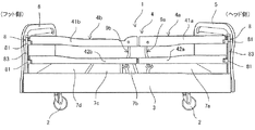
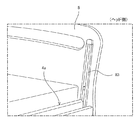
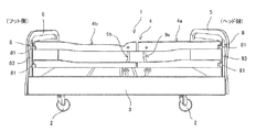
【課題】サイドレールが設置された状態で使用者の全身を保護することができ、必要に応じて部分的に上げ下げすることができるベッドのサイドレールの構造を提供する。【解決手段】ヘッドボード5とフットボード6とを備えたベッド1の側部に設けられるサイドレール4の構造であって、サイドレール4は、ヘッド側サイドレール4aとフット側サイドレール4bとを備え、ヘッドボード5は、ヘッド側サイドレール4aの一端部を支持するサイドレール支持機構8を備え、フットボード6は、フット側サイドレール4bの一端部を支持するサイドレール支持機構8を備え、ベッド1の側部のベッド長手方向の中央部付近には、ヘッド側サイドレール4aの他端部を支持するサイドレール昇降機構9aと、フット側サイドレール4bの他端部を支持するフット側のサイドレール昇降機構9bと、を備えることを特徴とする。【選択図】図1Provided is a bed side rail structure which can protect the whole body of a user in a state where the side rail is installed and can be partially raised and lowered as necessary. A side rail 4 is provided on a side portion of a bed 1 having a head board 5 and a foot board 6. The side rail 4 includes a head side side rail 4a and a foot side side rail 4b. The headboard 5 includes a side rail support mechanism 8 that supports one end of the head side rail 4a, and the footboard 6 includes a side rail support mechanism 8 that supports one end of the foot side rail 4b. Near the central portion of the side of the bed 1 in the longitudinal direction of the bed, there is a side rail lifting mechanism 9a that supports the other end of the head side rail 4a and a foot side that supports the other end of the foot side rail 4b. And a side rail elevating mechanism 9b. [Selection] Figure 1
Description
本発明は、サイドレールの構造に係り、特に、ベッドの側部に設けられるサイドレールの構造に関する。 The present invention relates to a structure of a side rail, and more particularly to a structure of a side rail provided on a side portion of a bed.
従来から、病院等で使用される医療用ベッド、施設や在宅等の介護で使用される介護用ベッドや家庭用ベッドには、ベッド使用者及び寝具等がベッドから落下することを防止するため、両側部に側柵(以下、サイドレールという)が取り付けられている。このサイドレールは、通常、ベッドのサイドフレームに脱着可能に取り付けられており、不要なときには取り外すことができるようになっている(特許文献1を参照)。 Conventionally, medical beds used in hospitals, nursing beds used for nursing care at homes and facilities, etc., to prevent bed users and bedding from falling from the bed, Side rails (hereinafter referred to as side rails) are attached to both sides. This side rail is normally detachably attached to the side frame of the bed, and can be removed when unnecessary (see Patent Document 1).
一般に、サイドレールの長さはベッドの側部の長さよりも短く形成されており、必要に応じて一方の側部に複数個のサイドレールが取り付けられる。 Generally, the length of the side rail is shorter than the length of the side portion of the bed, and a plurality of side rails are attached to one side portion as necessary.
例えば、ベッド使用者がベッドに乗り降りする際にサイドレールが邪魔にならないように、ベッドの乗り降りするサイド側においては、サイドレールを上体部側に装着して、足下側には装着しないといった使用の仕方もある。 For example, in order to prevent the side rail from getting in the way when the bed user gets on and off the bed, use the side rail on the upper body side on the side where the bed gets on and off, not on the foot side There is also a way.
しかしながら、特許文献1のような構成では、取り外したサイドレールが邪魔になるため、片付けるスペースが必要になるという問題があった。
However, the configuration as disclosed in
そこで、上記問題を解決するために、ベッド側面の全体を一続きのサイドレールで覆い、そのサイドレールをヘッドボードとフットボードに配置したレールに沿って上げ下げするようにしたものも知られている(特許文献2を参照)。
このように構成することで、サイドレールを取り外すことなく上げ下げができるので、サイドレールを片付けるスペースを設ける必要がなくなる。
Therefore, in order to solve the above problem, there is also known one in which the entire side surface of the bed is covered with a continuous side rail, and the side rail is raised and lowered along the rails arranged on the headboard and the footboard. (See Patent Document 2).
With this configuration, the side rail can be lifted and lowered without removing the side rail, so there is no need to provide a space for clearing the side rail.
また、その他の技術として、ベッドのサイドレールの構成において、サイドレールをベッドの中央付近で分割して配置し、テレスコピック式の縦桟やレール式の縦桟により部分的に上げ下げが可能に構成したものが知られている(特許文献3を参照)。
このように構成することで、特許文献2のようにサイドレール全体を上げ下げするのではなく、頭側のみまたは足側のみというように必要な箇所のみを上げ下げできるので、それ以外はサイドレールにより保護されて使用者の安全を確保できる。
As another technology, in the configuration of the bed side rail, the side rail is divided and arranged near the center of the bed, and it can be partially raised and lowered by a telescopic vertical rail or rail type vertical rail. Is known (see Patent Document 3).
By configuring in this way, instead of raising and lowering the entire side rail as in
また、さらに、その他の技術として、サイドレールを使用者の頭側と足側とに分割して配置して、使用状態に応じて所望する側のサイドレールを側方に開放した後にベッド下部に収納するようにしたものが提案されている(特許文献4を参照)。
このように構成することで、頭側のみまたは足側のみというように必要な箇所のみを開放でき、開放したサイドレールは邪魔にならないようにベッド下部に収納することができる。
Furthermore, as another technique, the side rail is divided into the user's head side and foot side, and the side rail on the desired side is opened to the side according to the state of use, and then the lower part of the bed. What was accommodated is proposed (refer patent document 4).
With this configuration, only necessary portions such as only the head side or only the foot side can be opened, and the opened side rail can be stored in the lower part of the bed so as not to get in the way.
しかしながら、特許文献2のような構成では、頭側付近または足側付近のサイドレールだけを部分的に上げ下げするといった使い方はできないという問題が生じる。
However, in the configuration as in
また、特許文献3のような構成では、ベッドからの乗り降りによく利用されるベッド中央付近のみを下げて使用することはできないという問題が生じる。
Further, in the configuration as in
さらに、特許文献4のような構成では、サイドレールをベッド下部に収納する構造上、ベッドの側部の中央付近の頭側のサイドレールと足側のサイドレールとの間に開放した空間が生じてしまうため、サイドレールにより保護された状態でも使用者の全身を保護することができないという問題が生じる。
Further, in the configuration as in
本発明は、上記従来の問題点に鑑みてなされたものであって、ベッドのサイドレールの構造において、サイドレールが設置された状態で使用者の全身を保護することができ、必要に応じて部分的に上げ下げすることができるサイドレールの構造を提供することを目的とする。 The present invention has been made in view of the above-described conventional problems, and in the structure of the bed side rail, the whole body of the user can be protected in a state where the side rail is installed. An object of the present invention is to provide a side rail structure that can be partially raised and lowered.
上述した課題を解決するための本発明に係るサイドレールの構造は、次の通りである。
本発明は、ヘッドボードとフットボードとを備えたベッドの側部に設けられるサイドレールの構造であって、前記サイドレールの構成として、ベッド長手方向の中央部付近で分離して配置されるヘッド側サイドレールとフット側サイドレールとを備えて、前記ヘッドボードには、前記ヘッド側サイドレールの一端部を昇降可能に支持するサイドレール支持機構(スライド機構)を備え、前記フットボードには、前記フット側サイドレールの一端部を昇降可能に支持するサイドレール支持機構(スライド機構)を備え、前記ベッドの側部のベッド長手方向の中央部付近には、前記ヘッド側サイドレールの一端部を支点として前記ヘッド側サイドレールの他端部を揺動可能に支持するとともに、前記他端部とともに昇降するヘッド側のサイドレール昇降機構(縦桟)と、前記フット側サイドレールの一端部を支点として前記フット側サイドレールの他端部を揺動可能に支持するとともに、前記他端部とともに昇降するフット側のサイドレール昇降機構(縦桟)と、を備えることを特徴とするものである。
The structure of the side rail which concerns on this invention for solving the subject mentioned above is as follows.
The present invention is a structure of a side rail provided on a side portion of a bed provided with a headboard and a footboard, and the head is arranged separately in the vicinity of the central portion in the bed longitudinal direction as the configuration of the side rail. A side rail and a foot side rail are provided, and the head board includes a side rail support mechanism (sliding mechanism) that supports one end of the head side side rail so as to be movable up and down. A side rail support mechanism (sliding mechanism) that supports one end portion of the foot side rail so as to be movable up and down is provided, and one end portion of the head side side rail is provided in the vicinity of the center portion of the bed side portion in the bed longitudinal direction. As a fulcrum, the other end of the head side rail is swingably supported, and the head side Elevating mechanism (vertical beam) and foot side rail lift that supports the other end of the foot side rail so as to be swingable with one end of the foot side rail as a fulcrum and moves up and down with the other end And a mechanism (vertical bar).
また、本発明は、前記ヘッド側サイドレールと前記フット側サイドレールの構成として、ベッド長手方向の中央部付近のそれぞれの端部を、前記ヘッドボード側の一端部または前記フットボード側の一端部よりも低い位置に配置し、ベッド長手方向の中央部付近が低くなるように傾斜した状態で配置されることが好ましい。 Further, according to the present invention, as the configuration of the head side rail and the foot side rail, each end near the center in the longitudinal direction of the bed is connected to one end on the headboard side or one end on the footboard side. It is preferable to arrange at a lower position and in an inclined state so that the vicinity of the center in the longitudinal direction of the bed is lowered.
また、本発明は、前記サイドレール支持機構には、前記ヘッド側サイドレールまたは前記フット側サイドレールの支持状態を保持する第1ストッパ部を備えることが好ましい。 In the present invention, it is preferable that the side rail support mechanism includes a first stopper portion that holds a support state of the head side side rail or the foot side side rail.
また、本発明は、前記サイドレール昇降機構の構成として、前記ヘッド側サイドレールまたは前記フット側サイドレールの他端部をそれぞれ支持する第1リンク(例えは、上縦桟)と、前記第1リンクを昇降させる第2リンク(例えば、下縦桟)と、前記第1リンクと前記第2リンクとを連結するリンク連結部と、前記ヘッド側サイドレールまたは前記フット側サイドレールの他端部を上昇させて所定位置にしたときの前記第1リンクと前記第2リンクの状態を保持する第2ストッパ部と、を備えることが好ましい。 Further, according to the present invention, as the configuration of the side rail elevating mechanism, a first link (for example, an upper vertical rail) that respectively supports the other end of the head side rail or the foot side rail, and the first rail A second link (e.g., a lower vertical rail) that raises and lowers the link, a link connecting portion that connects the first link and the second link, and the other end of the head side rail or the foot side rail. It is preferable to include a second stopper portion that holds the state of the first link and the second link when raised to a predetermined position.
また、本発明は、前記ヘッド側サイドレールと前記フット側サイドレールが、上下方向で並設される上サイドレールと下サイドレールとを有して構成されることが好ましい。 In the present invention, it is preferable that the head side rail and the foot side rail have an upper side rail and a lower side rail arranged in parallel in the vertical direction.
また、本発明は、前記下サイドレールが前記リンク連結部に支持されるように構成することが好ましい。 Moreover, it is preferable that this invention is comprised so that the said lower side rail may be supported by the said link connection part.
また、本発明は、前記下サイドレールが、昇降動作のうちの最下位置に配置される状態で、前記第2リンクが支持される支持部に支持されるように構成することが好ましい。 Moreover, it is preferable that this invention is comprised so that the said lower side rail may be supported by the support part in which the said 2nd link is supported in the state arrange | positioned in the lowest position of raising / lowering operation | movement.
本発明のサイドレールの構造によれば、ヘッドボードとフットボードとを備えたベッドの側部に設けられるサイドレールの構造であって、前記サイドレールの構成として、ベッド長手方向の中央部付近で分離して配置されるヘッド側サイドレールとフット側サイドレールとを備えて、前記ヘッドボードには、前記ヘッド側サイドレールの一端部を昇降可能に支持するサイドレール支持機構を備え、前記フットボードには、前記フット側サイドレールの一端部を昇降可能に支持するサイドレール支持機構を備え、前記ベッドの側部のベッド長手方向の中央部付近には、前記ヘッド側サイドレールの一端部を支点として前記ヘッド側サイドレールの他端部を揺動可能に支持するとともに、前記他端部とともに昇降するヘッド側のサイドレール昇降機構と、前記フット側サイドレールの一端部を支点として前記フット側サイドレールの他端部を揺動可能に支持するとともに、前記他端部とともに昇降するフット側のサイドレール昇降機構と、を備えることで、ヘッド側サイドレールおよびフット側サイドレールが設置された状態で使用者の全身を保護することができ、サイドレールを着脱することなく、必要に応じてヘッド側サイドレールまたはフット側サイドレールを部分的に上げ下げすることができるサイドレールの構造を実現できる。 According to the structure of the side rail of the present invention, the structure of the side rail is provided on the side portion of the bed including the headboard and the footboard, and the side rail is configured in the vicinity of the central portion in the bed longitudinal direction. A head-side side rail and a foot-side side rail arranged separately; and the head board includes a side rail support mechanism that supports one end of the head-side side rail so as to be movable up and down. Is provided with a side rail support mechanism for supporting one end of the foot side rail so that it can be moved up and down, and the one end of the head side side rail is a fulcrum in the vicinity of the center of the bed in the longitudinal direction of the bed. As described above, the head-side side rail is raised and lowered while supporting the other end of the head-side side rail in a swingable manner. And a foot-side side rail lifting mechanism that supports the other end of the foot-side side rail in a swingable manner with one end of the foot-side side rail as a fulcrum, and moves up and down with the other end. Therefore, it is possible to protect the whole body of the user with the head-side side rail and foot-side side rail installed, and without removing the side rail, the head-side side rail or the foot-side side rail as required. It is possible to realize a side rail structure capable of partially raising and lowering.
以下、本発明のサイドレールの構造を実施するための形態について図面を参照して詳細に説明する。
図1は本発明を実施する形態の一例であって、本発明の実施形態に係るサイドレールの構造を備えたベッドの概略の構成を示す側面視による説明図、図2は前記サイドレールを支持するサイドレール支持機構の構成を示す説明図、図3は前記サイドレール支持機構によりサイドレールをスライドさせた状態を示す説明図、図4は前記ベッドのヘッドボード側のサイドレール支持機構の構成を示す説明図、図5は前記ベッドのヘッドボード側のスライドレールの取付状態を示す説明図、図6は前記ベッドのヘッドボードに設けられる第1ストッパの取付位置を示す説明図である。
Hereinafter, embodiments for implementing the structure of the side rail of the present invention will be described in detail with reference to the drawings.
FIG. 1 is an example of an embodiment for carrying out the present invention, and is an explanatory view showing a schematic configuration of a bed having a structure of a side rail according to an embodiment of the present invention, and FIG. 2 supports the side rail. FIG. 3 is an explanatory diagram showing a state in which the side rail is slid by the side rail support mechanism, and FIG. 4 is a diagram showing a configuration of the side rail support mechanism on the headboard side of the bed. FIG. 5 is an explanatory view showing a mounting state of a slide rail on the headboard side of the bed, and FIG. 6 is an explanatory view showing a mounting position of a first stopper provided on the headboard of the bed.
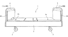
本実施形態は、図1に示すように、マットレスが載置されるベッドフレーム3の側部にサイドレール4が設けられたベッド1において、本発明の特徴的なサイドレールの構造を採用したものである。
In this embodiment, as shown in FIG. 1, a
ベッド1のヘッド側とフット側には、それぞれヘッドボード5,フットボード6が設けられている。
A
ベッドフレーム3には、背ボトム7a、腰ボトム7b、膝ボトム7c及び脚ボトム7dを含む複数個のボトムが長手方向に並置されている。マットレス(図示省略)は、ヘッド側からフット側に沿った方向に長い矩形状に形成され、複数のボトム上に載置される。
ベッドフレーム3の下部には、移動用キャスタ2が設けられている。
On the
A moving
ここで、本実施形態の特徴的なサイドレール4の構造について図面を参照して詳細に説明する。
Here, the structure of the
本実施形態のサイドレール4は、図1に示すように、ベッド1の長手方向の側部の中央部付近で分離して配置されるヘッド側サイドレール4aとフット側サイドレール4bとを備えて構成されている。
As shown in FIG. 1, the
ヘッド側サイドレール4aは、ヘッドボード5側から中央部付近にわたり、ベッド使用者の上体部に対応して設けられている。フット側サイドレール4bは、フットボード6側から中央部付近にわたり、ベッド使用者の下体部に対応して設けられている。
The head-
ヘッド側サイドレール4aとフット側サイドレール4bは、それぞれ上下方向で並設される上サイドレール41a,41bと下サイドレール42a,42bとにより構成されている。
The head-
ヘッドボード5およびフットボード6には、ヘッド側サイドレール4aとフット側サイドレール4bをそれぞれ上下方向に移動可能に支持するサイドレール支持機構8が設けられている。
The
(サイドレール支持機構)
サイドレール支持機構8は、ヘッドボード5およびフットボード6に同様な構成で設けられるため、ここではヘッドボード5側のサイドレール支持機構8を例に挙げて説明する。
(Side rail support mechanism)
Since the side
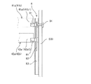
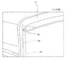
サイドレール支持機構8は、図2,図3に示すように、ヘッド側サイドレール4aを支持する支持部材81、支持部材81を保持する保持部材82と、保持部材82をスライド可能に支持するスライドレール83と、第1ストッパ部84を備えて構成されている。
2 and 3, the side
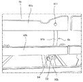
支持部材81は、図4に示すように、ヘッドボード5に設けられたスライドレール83に配置されて、ヘッド側サイドレール4aを構成する上サイドレール41aと下サイドレール42aとの一端部41a1,42a1をそれぞれ回動可能に支持する。
As shown in FIG. 4, the
保持部材82は、図2に示すように、2個の支持部材81を所定の間隔をとって一体的に取付けた状態で、スライドレール83に移動可能に取付けられている。すなわち、図2,図3に示すように、保持部材82により2個の支持部材81が一体的に動作するようにされている。
As shown in FIG. 2, the holding
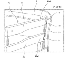
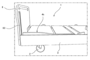
スライドレール83は、図5に示すように、ヘッドボード5の側端部にベッドフレーム3に隣接して上下方向に長く設置されている。
As shown in FIG. 5, the
第1ストッパ部84は、図2,図6に示すように、ヘッドボード5の外側より、ヘッドボード5を通ってスライドレール83と保持部材82に対して所定位置で抜き差し操作が可能に設けられている。
As shown in FIGS. 2 and 6, the
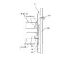
具体的には、ヘッド側の上サイドレール41aと下サイドレール42aとを支持する支持部材81が連結される保持部材82がスライドレール83に対して所定位置に配置されたとき、第1ストッパ部84をヘッドボード5の外側から保持部材82に到達するまで挿入することで、保持部材82を所定位置でスライドレール83に固定することができる。これにより、ヘッド側の上サイドレール41aと下サイドレール42aとを所定位置に配置することができる。このとき、上サイドレール41aと下サイドレール42aとは、支持部材81に回動可能に支持されている。
Specifically, when the holding
また、保持部材82がスライドレール83の所定位置に配置された状態から、第1ストッパ部84を保持部材82から外れる位置まで抜き出すことで、図3に示すように、保持部材82は、スライドレール83に沿って移動可能となる。これにより、図5に示すように、ヘッド側サイドレール4aを下方に移動することでベッドフレーム3の内側に収納することができる。
Further, by pulling out the
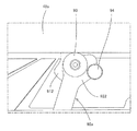
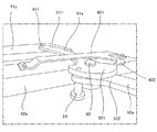
ベッド1の側部のベッドフレーム3のベッド長手方向の中央部付近には、図1に示すように、ヘッド側サイドレール4aの他端部を支持する縦桟として機能するヘッド側のサイドレール昇降機構9aと、フット側サイドレール4bの他端部を支持する縦桟として機能するフット側のサイドレール昇降機構9bと、が設けられている。
As shown in FIG. 1, in the vicinity of the center of the
ヘッド側のサイドレール昇降機構9aは、ヘッド側サイドレール4aの上サイドレール41aと下サイドレール42aのヘッド側の一端部41a1,42a1を支点として中央部付近の他端部41a2,42a2を揺動可能に支持するとともに、他端部41a2,42a2とともに昇降するように構成されている。
The side
フット側のサイドレール昇降機構9bもヘッド側のサイドレール昇降機構9aと同様に、フット側サイドレール4bの上サイドレール41bと下サイドレール42bの一端部41b1,42b1を支点としてフット側サイドレール4bの他端部41b2,42b2を揺動可能に支持するとともに、他端部41b2,42b2とともに昇降するように構成されている。
Similarly to the head side side
(サイドレール昇降機構)
ヘッド側とフット側のサイドレール昇降機構9a,9bは、図1に示すように、左右対称に構成されており、各部構成も同様な機能を備えているため、ヘッド側のサイドレール昇降機構9aを例に挙げて説明する。
(Side rail lifting mechanism)
As shown in FIG. 1, the head-side and foot-side side
図7は本発明の実施形態に係るサイドレールの構造を構成するサイドレール昇降機構の構成を示す側面視による説明図、図8は前記サイドレール昇降機構の構成を示すベッド内側視による説明図、図9は前記サイドレール昇降機構を構成するリンク機構のヒンジ部周辺の構成を示す側面視による説明図、図10は前記ヒンジ部周辺の構成を示すベッド内側視による説明図、図11は前記リンク機構のストッパ部がセットされた状態を示す説明図、図12は前記リンク機構のストッパ部が解除された状態を示す説明図、図13は前記サイドレール昇降機構を構成するリンク機構をガイドするガイド部の構成を示す説明図、図14は前記ガイド部のフック部とヒンジ部とが係合した状態を示す説明図、図15は前記フック部からヒンジ部が外れたときのリンク機構の動作状態の一態様を示す説明図、図16は前記フック部からヒンジ部が外れた状態を示す説明図、図17は前記ガイド部とリンク機構の構成を示す斜視図、図18は前記サイドレール昇降機構によりサイドレールの端部が最下位置まで下降した状態を示す側面視による説明図、図19は前記サイドレール昇降機構によりサイドレールの端部が最下位置まで下降した状態を示すベッド内側視による説明図、図20は前記サイドレールの他端部を最下位置に下降するとともに前記サイドレール昇降機構によりサイドレールの端部を最下位置まで下降した状態を示す側面視による説明図、図21は前記サイドレールの他端部を最下位置に下降するとともに前記サイドレール昇降機構によりサイドレールの端部を最下位置まで下降した状態を示すベッド内側視による説明図である。 FIG. 7 is a side view illustrating the configuration of the side rail lifting mechanism that constitutes the structure of the side rail according to the embodiment of the present invention. FIG. 8 is an explanatory diagram illustrating the configuration of the side rail lifting mechanism from the inside of the bed. 9 is a side view showing the structure around the hinge part of the link mechanism constituting the side rail lifting mechanism, FIG. 10 is a side view showing the structure around the hinge part, and FIG. 11 is the link inside view. FIG. 12 is an explanatory view showing a state in which the stopper portion of the link mechanism is released, and FIG. 13 is a guide for guiding the link mechanism constituting the side rail lifting mechanism. FIG. 14 is an explanatory view showing a state where the hook portion and the hinge portion of the guide portion are engaged, and FIG. 15 is a view showing the hinge portion removed from the hook portion. FIG. 16 is an explanatory view showing a state in which the hinge part is detached from the hook part, FIG. 17 is a perspective view showing a configuration of the guide part and the link mechanism, and FIG. 18 is an explanatory view in a side view showing a state in which the end portion of the side rail is lowered to the lowest position by the side rail lifting mechanism, and FIG. 19 is a view in which the end portion of the side rail is lowered to the lowest position by the side rail lifting mechanism. FIG. 20 is a side view showing a state in which the other end portion of the side rail is lowered to the lowest position and the end portion of the side rail is lowered to the lowest position by the side rail lifting mechanism. FIG. 21 is a diagram illustrating the side rail, and the other end of the side rail is lowered to the lowest position and the end of the side rail is lowered to the lowest position by the side rail lifting mechanism. And is an explanatory diagram according bed inside view showing a state.
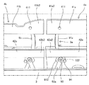
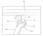
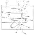
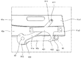
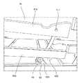
ヘッド側のサイドレール昇降機構9aは、図7に示すように、ヘッド側サイドレール4aの上サイドレール41aと下サイドレール42aのそれぞれの他端部41a2,42a2をそれぞれ支持する第1リンク(上縦桟)91aと、第1リンク91aを昇降させる第2リンク(下縦桟)92aと、第1リンク91aと第2リンク92aとを連結するヒンジ部(リンク連結部)93と、ヘッド側サイドレール4aの上サイドレール41aと下サイドレール42aのそれぞれの他端部41a2,42a2を上昇させたときの第1リンク91aと第2リンク92aの状態を保持する第2ストッパ部94と、を備える。
As shown in FIG. 7, the head side side
サイドレール昇降機構9aは、第1リンク91aと第2リンク92aとにより構成されるリンク機構によって、ヘッド側サイドレール4aを昇降させるように構成されている。
The side
第1リンク91aは、一端部911が上サイドレール41aの一端部41a1に支持部411により回動可能に軸支され、他端部912がヒンジ部93により第2リンク92aの他端部922と回動可能に連結されている。さらに、第1リンク91aは、上サイドレール41aとヒンジ部93との間で、下サイドレール42aの他端部42a2に長手方向に沿って設けられるガイド部421により下サイドレール42aの側面に沿って上下方向、ベッド長手方向に移動可能に取付けられている。
The
下サイドレール42aの他端部42a2は、図9に示すように、ヒンジ部93により下方より支持されるとともに、図10に示すように、ガイド部421により第1リンク91aに沿って上下方向、ベッド長手方向に移動可能に設けられている。
The other end portion 42a2 of the
第2リンク92aは、図8に示すように、他端部922がヒンジ部93により第1リンク91aの他端部912と回動可能に連結され、他端部(図示省略)がベッドフレーム3に回動可能に軸支されている。
As shown in FIG. 8, the
サイドレール昇降機構9aは、図7,図8に示すように、第1リンク91aと第2リンク92aとを上下方向に立ち上がらせた状態を第2ストッパ部94により保持することで、ヘッド側サイドレール4aの上サイドレール41aと下サイドレール42aとを略平行に配置した状態を保持するように構成されている。
As shown in FIGS. 7 and 8, the side
そして、第1リンク91aと第2リンク92aとを保持した状態から第2ストッパ部94を外すことで、図11,図12に示すように、第1リンク91aと第2リンク92aとが折り畳まれて、上サイドレール41aと下サイドレール42aとが下降するように構成されている。
And by removing the
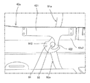
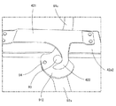
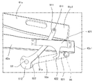
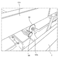
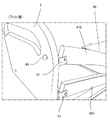
ガイド部421には、図8,図10に示すように、ヒンジ部93が係合されるフック部422が突設されている。フック部422は、図13,図14に示すように、上サイドレール41aを完全に上げた状態で、下サイドレール42aのガイド部421のフック部422とヒンジ部93が係合して、下サイドレール42aの他端部42a2は上下方向の動きが抑制されるようになっている。
As shown in FIGS. 8 and 10, the
具体的には、フック部422は、図14に示すように、ヒンジ部93と係合した状態で、ヒンジ部93の側部から下部を包囲するように湾曲して形成されている。すなわち、フック部422は、ヒンジ部93の側部から下部に亘り当接するように形成されている。これにより、フック部422がヒンジ部93の上下方向の動きを抑制することができる。
Specifically, as shown in FIG. 14, the
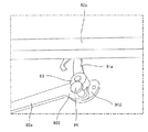
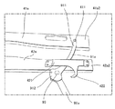
そして、第1リンク91aと第2リンク92aとを保持した状態から第2ストッパ部94を外すことで、第1リンク91aと第2リンク92aとが折り畳まれると、図15,図16に示すように、ガイド部421のフック部422からヒンジ部93が外れて、第1リンク91aが下降可能な状態になる。これにより、第1リンク91aが下降しながら倒れるように動作することで、上サイドレール41aの他端部41a2は第1リンク91aの一端部911とともに下降し、下サイドレール42aの他端部42a2はヒンジ部93とともに下降するように構成されている。
Then, when the
下サイドレール42aは、図17に示すように、ガイド部421により第1リンク91aが移動可能に挟持されて、ベッド幅方向の動きが抑制されている。
As shown in FIG. 17, the
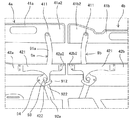
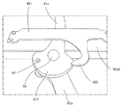
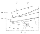
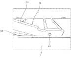
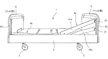
上サイドレール41aと下サイドレール42aの他端部41a2,42a2が最下位置に下降して、上サイドレール41aと下サイドレール42aとが傾斜した状態のときは、図18,図19に示すように、第2リンク92aの一端部921とベッドフレーム3とを連結するヒンジ95の上に下サイドレール42aの他端部42a2が配置された状態で、その上に上サイドレール41aの他端部41a2が重なり合った状態となる。
When the other end portions 41a2 and 42a2 of the
このとき、ヒンジ部93は、下サイドレール42aの下面より大きく離れた状態となる。このように、ヒンジ部93が下サイドレール42aに拘束されず上下方向に移動可能に配置されることで、上サイドレール41aと下サイドレール42aの動作を規制することなく下降することができる。
At this time, the
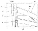
また、上サイドレール41aと下サイドレール42aの一端部41a1,42a1を最下位置に下降した状態で、他端部41a2,42a2を最下位置に下降した場合は、図20,図21に示すように、上サイドレール41aと下サイドレール42aとが重なり合った状態でヒンジ95の上に配置される。
Further, when the other end portions 41a2 and 42a2 are lowered to the lowermost position while the one end portions 41a1 and 42a1 of the
次に、本実施形態のサイドレールの構造を採用したベッド1において、サイドレール4を昇降させる動作について図面を参照して説明する。
Next, in the
図22は本実施形態のサイドレールの構造を採用したベッドにおいてサイドレールを上昇位置にセットした状態を示す説明図、図23は前記サイドレールのフット側サイドレールのサイドレール昇降機構の状態を示す説明図、図24は前記サイドレール昇降機構を構成するリンク機構のストッパ部を外した状態を示す説明図、図25は前記リンク機構が折り畳まれて下降する状態を示す説明図、図26は前記フット側サイドレールのベッド中央部付近の端部が下降した状態を示す説明図、図27前記フット側サイドレールのベッド中央部付近の端部が下降したときの前記フット側サイドレールのフットボード側の端部の状態を示す説明図、図28は前記フット側サイドレールのフットボード側の端部の状態を示す側面視による説明図、図29は前記フット側サイドレールのフットボード側の端部が下降途中の状態を示す説明図、図30は前記フット側サイドレールのフットボード側の端部が最下位置まで下降した状態を示す説明図、図31は前記フット側サイドレールが全体的に下降したときのベッドの全体を示す説明図、図32はフット側サイドレールに加えてヘッド側サイドレールのベッド中央部付近の端部が下降したときのベッド全体の説明図、図33はサイドレール全てが下降したときのベッド全体の説明図、図34はフット側サイドレールとヘッド側サイドレールのベッド中央部付近の端部が下降した状態を示すベッド全体の説明図である。 FIG. 22 is an explanatory view showing a state in which the side rail is set at the raised position in the bed adopting the side rail structure of the present embodiment, and FIG. 23 shows a state of the side rail lifting mechanism of the foot side side rail of the side rail. FIG. 24 is an explanatory view showing a state in which the stopper portion of the link mechanism constituting the side rail lifting mechanism is removed, FIG. 25 is an explanatory view showing a state in which the link mechanism is folded and lowered, and FIG. FIG. 27 is an explanatory view showing a state where the end of the foot side side rail near the center of the bed is lowered. FIG. 27 is the foot side of the foot side side rail when the end of the foot side side rail near the center of the bed is lowered. FIG. 28 is an explanatory view showing the state of the foot side end of the foot side rail, and FIG. 29 is a side view showing the state of the end of the foot side rail. FIG. 30 is an explanatory view showing a state in which the footboard side end of the foot side rail is in the middle of lowering, FIG. 30 is an explanatory view showing a state in which the footboard side end of the foot side rail is lowered to the lowest position, FIG. 31 is an explanatory view showing the entire bed when the foot side rail is lowered as a whole, and FIG. 32 is a view when the end of the head side side rail near the center of the bed is lowered in addition to the foot side rail. 33 is an explanatory diagram of the entire bed, FIG. 33 is an explanatory diagram of the entire bed when all of the side rails are lowered, and FIG. 34 is a state in which the ends of the foot side side rail and the head side side rail near the center of the bed are lowered. It is explanatory drawing of the whole bed.
ベッド1に側部に設けられたサイドレール4が、図22に示すように上昇した状態から下降させる場合について説明する。
The case where the
まず、サイドレール4のフット側サイドレール4bを下降させる場合について説明する。
First, the case where the
フット側サイドレール4bのベッド中央部付近の端部を下降させる場合は、図23に示すように起立した状態のサイドレール昇降機構9bから、図24に示すように、第1リンク91bと第2リンク92bを固定している第2ストッパ部94を所定量抜き出す。
When lowering the end of the
第2ストッパ部94による保持状態が解除された第1リンク91bと第2リンク92bは、図25に示すように、ヒンジ部93を支点として折り畳まれて下降する。
As shown in FIG. 25, the
これにより上サイドレール41bと下サイドレール42bのベッド中央部付近の端部側が下降して、図26に示すように、ベッドフレーム3の内側に収納される状態となる。
As a result, the end sides of the
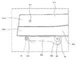
次に、サイドレール4のフット側サイドレール4bのフットボード6側の端部を下降させる場合は、図27に示すように、フットボード6の背面に装着された第1ストッパ部84を所定量抜き出して、図28に示すように、スライドレール83に沿って支持部材81を上下方向に移動可能な状態にする。
Next, when lowering the end of the foot
これにより、支持部材81により回動可能に支持された上サイドレール41bと下サイドレール42bの端部は、図29,図30に示すように、スライドレール83に沿って下降して、ベッドフレーム3の内側に収納される状態となる。
As a result, the end portions of the
このようにして、フット側サイドレール4bは、図31に示すように、略平行な状態でベッドフレーム3の内側に収納される。これにより、ベッド使用者は、ベッド1のフット側サイドレール4bを取り外すことなくベッド側部より無くすことができるので、ベッド1のフット側からの乗り降りを容易に行うことができる。
In this way, the
次に、さらに、サイドレール4のヘッド側サイドレール4aを下降させる場合について説明する。
Next, the case where the head
ヘッド側サイドレール4aのベッド中央部付近の端部を下降させる場合は、フット側サイドレール4bを下降する場合と同様に、第1リンク91aと第2リンク92aを固定している第2ストッパ部94を所定量抜き出して、第1リンク91aと第2リンク92aは、図25に示すように、ヒンジ部93を支点として折り畳まれて下降する。
When lowering the end of the head
これにより、上サイドレール41aと下サイドレール42aのベッド中央部付近の端部側が下降して、図32に示すように、ベッドフレーム3の内側に収納される状態となる。
As a result, the end sides of the
このように、ベッド1の側部の中央部付近で、フット側サイドレール4bが全てベッドフレーム3の内側に収納され、さらに、ヘッド側サイドレール4aのベッド中央部付近の端部がベッドフレーム3の内側に収納されてヘッド側サイドレール4aがベッド中央部付近の端部側が低くなるように傾斜することで、ベッド使用者は、さらに、ベッド1の中央部付近からフット側にわたる範囲で乗り降りを容易に行うことができる。
Thus, the foot
さらに、ヘッド側サイドレール4aのヘッドボード5側の端部を、前述したフット側サイドレール4bのフットボード6側の端部を下降させる場合と同様な操作で下降することで、図33に示すように、フット側サイドレール4bおよびヘッド側サイドレール4aを全てサイドレール昇降機構9a,9bとともにベッドフレーム3の内側に収納することができるので、ベッド1の側部をヘッド長手方向にわたり開放することができる。
Furthermore, the end of the
なお、上述した操作と逆の操作を行うことで、ベッド1の側部にヘッド側サイドレール4aとフット側サイドレール4bを用途に応じた状態に設置することができる。
In addition, the head
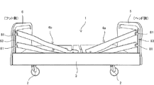
また、変形例として、図34に示すように、ヘッド側サイドレール4aとフット側サイドレール4bのベッド中央部付近の端部のみを下降して、ベッド中央部付近を開放するように設置することもできる。このように構成することで、ベッド使用者に対してベッド中央部付近より介護等を容易におこなうことが可能になる。
As a modification, as shown in FIG. 34, the head
以上のように構成したので、本実施形態によれば、ヘッドボード5とフットボード6とを備えたベッド1の側部に設けられるサイドレール4の構造であって、サイドレール4の構成として、ベッド長手方向の中央部付近で分離して配置されるヘッド側サイドレール4aとフット側サイドレール4bとを備えて、ヘッドボード5には、ヘッド側サイドレール4aの一端部を昇降可能に支持するサイドレール支持機構8を備え、フットボード6には、フット側サイドレール4bの一端部を昇降可能に支持するサイドレール支持機構8を備え、ベッド1の側部のベッド長手方向の中央部付近には、ヘッド側サイドレール4aの一端部を支点としてヘッド側サイドレール4aの他端部を揺動可能に支持するとともに、他端部とともに昇降するヘッド側のサイドレール昇降機構9aと、フット側サイドレール4bの一端部を支点としてフット側サイドレール4bの他端部を揺動可能に支持するとともに、他端部とともに昇降するフット側のサイドレール昇降機構9bと、を備えることで、ヘッド側サイドレール4aおよびフット側サイドレール4bが設置された状態で使用者の全身を保護することができる。また、サイドレールを着脱することなく、必要に応じてヘッド側サイドレールまたはフット側サイドレールを部分的に上げ下げすることができるので、ベッド使用者を容易に介護することができるとともに、ベッド使用者が容易にベッドへの乗り降りを行うことができる。
Since it comprised as mentioned above, according to this embodiment, it is the structure of the
また、本実施形態では、ガイド部421にフック部422を設けて、第1リンク91a,91bと第2リンク92a,92bとが起立した状態で、ヒンジ部93とフック部422が係合するように構成したので、第1リンク91a,91bと第2リンク92a,92bと所定位置に容易に配置することができ、第2ストッパ部94による位置決め固定する操作を容易に行うことができる。
Further, in the present embodiment, the
さらに、第1リンク91a,91bと第2リンク92a,92bとが起立した状態で、フック部422とヒンジ部93とがかみ込むことで、自由度がなくなり、第1リンク91a,91bと第2リンク92a,92bとがしっかり固定され保持状態を安定させることができる。なお、フック部422の形状は本実施形態の形状に限定されるものではない。
Furthermore, when the
また、本発明は、上述した実施形態や変形例に限定されるものではなく、請求項に示した範囲で種々の変更が可能である。すなわち、本発明の要旨を逸脱しない範囲内において適宜変更した技術的手段を組み合わせて得られる実施形態についても本発明の技術的範囲に含まれる。 The present invention is not limited to the above-described embodiments and modifications, and various modifications can be made within the scope shown in the claims. That is, embodiments obtained by combining technical means appropriately changed within the scope not departing from the gist of the present invention are also included in the technical scope of the present invention.
本発明のサイドレールの構造は、医療用、介護用、家庭用のベッド等に利用することができる。 The structure of the side rail of the present invention can be used for medical, nursing, home beds and the like.
1 ベッド
3 ベッドフレーム
4 サイドレール
4a ヘッド側サイドレール
4b フット側サイドレール
5 ヘッドボード
6 フットボード
8 サイドレール支持機構
9a,9b サイドレール昇降機構
41a,41b 上サイドレール
41a1,42a1,41b1,42b1 一端部
41a2,42a2,41b2,42b2 他端部
42a,42b 下サイドレール
81 支持部材
82 保持部材
83 スライドレール
84 第1ストッパ部
91a,91b 第1リンク
92a,92b 第2リンク
93 ヒンジ部(リンク連結部)
94 第2ストッパ部
411 支持部
421 ガイド部
422 フック部
911,921 一端部
912,922 他端部
1
94
Claims (7)
前記サイドレールは、ベッド長手方向の中央部付近で分離して配置されるヘッド側サイドレールとフット側サイドレールとを備えて構成され、
前記ヘッドボードは、前記ヘッド側サイドレールの一端部を昇降可能に支持するサイドレール支持機構を備え、
前記フットボードは、前記フット側サイドレールの一端部を昇降可能に支持するサイドレール支持機構を備え、
前記ベッドの側部のベッド長手方向の中央部付近には、
前記ヘッド側サイドレールの一端部を支点として前記ヘッド側サイドレールの他端部を揺動可能に支持するとともに、前記他端部とともに昇降するヘッド側のサイドレール昇降機構と、
前記フット側サイドレールの一端部を支点として前記フット側サイドレールの他端部を揺動可能に支持するとともに、前記他端部とともに昇降するフット側のサイドレール昇降機構と、
を備えることを特徴とするサイドレールの構造。 The structure of the side rail provided on the side of the bed with a headboard and footboard,
The side rail is configured to include a head side rail and a foot side rail that are arranged separately in the vicinity of the center in the bed longitudinal direction,
The headboard includes a side rail support mechanism that supports one end of the head side rail so as to be movable up and down.
The footboard includes a side rail support mechanism that supports one end of the foot side rail so that it can be raised and lowered.
In the vicinity of the central part in the bed longitudinal direction of the side of the bed,
A head-side side rail lifting mechanism that supports the other end of the head-side side rail swingably with one end of the head-side side rail as a fulcrum;
A foot-side side rail lifting mechanism that supports the other end of the foot-side side rail in a swingable manner with one end of the foot-side side rail as a fulcrum, and that moves up and down with the other end.
The structure of the side rail characterized by comprising.
ベッド長手方向の中央部付近のそれぞれの端部が、前記ヘッドボード側の一端部または前記フットボード側の一端部よりも低い位置に配置され、
ベッド長手方向の中央部付近が低くなるように傾斜した状態で配置されることを特徴とする請求項1に記載のサイドレールの構造。 The head side rail and the foot side rail are
Each end near the center in the longitudinal direction of the bed is disposed at a position lower than one end on the headboard side or one end on the footboard side,
The side rail structure according to claim 1, wherein the side rail structure is arranged in an inclined state so as to be lowered in the vicinity of the central portion in the bed longitudinal direction.
Priority Applications (1)
| Application Number | Priority Date | Filing Date | Title |
|---|---|---|---|
| JP2016195825A JP2018057504A (en) | 2016-10-03 | 2016-10-03 | Structure of side-rail |
Applications Claiming Priority (1)
| Application Number | Priority Date | Filing Date | Title |
|---|---|---|---|
| JP2016195825A JP2018057504A (en) | 2016-10-03 | 2016-10-03 | Structure of side-rail |
Publications (1)
| Publication Number | Publication Date |
|---|---|
| JP2018057504A true JP2018057504A (en) | 2018-04-12 |
Family
ID=61907911
Family Applications (1)
| Application Number | Title | Priority Date | Filing Date |
|---|---|---|---|
| JP2016195825A Pending JP2018057504A (en) | 2016-10-03 | 2016-10-03 | Structure of side-rail |
Country Status (1)
| Country | Link |
|---|---|
| JP (1) | JP2018057504A (en) |
Cited By (1)
| Publication number | Priority date | Publication date | Assignee | Title |
|---|---|---|---|---|
| IT201900021348A1 (en) * | 2019-11-15 | 2021-05-15 | Luca Pietrobon | Bed rail system |
-
2016
- 2016-10-03 JP JP2016195825A patent/JP2018057504A/en active Pending
Cited By (2)
| Publication number | Priority date | Publication date | Assignee | Title |
|---|---|---|---|---|
| IT201900021348A1 (en) * | 2019-11-15 | 2021-05-15 | Luca Pietrobon | Bed rail system |
| EP3821867A1 (en) * | 2019-11-15 | 2021-05-19 | Luca PIETROBON | Bed rail system |
Similar Documents
| Publication | Publication Date | Title |
|---|---|---|
| JP6278983B2 (en) | Bed equipment | |
| CN105120820B (en) | bottom plate of bed unit | |
| US6564404B1 (en) | Liftable side rail for a lying table such as a bed | |
| US6691345B2 (en) | Lifting mechanism for liftable side rails for a lying table such as a bed | |
| TW202402258A (en) | Nursing care device | |
| KR20120000687U (en) | Frame structure of medical bed | |
| US10617218B2 (en) | Method for adjusting mattresses into an operating position and mechanism for performing said method | |
| JP2016168098A (en) | Side fence attached to bed | |
| JP2018057504A (en) | Structure of side-rail | |
| GB2517311A (en) | Folding and Unfolding Structure for Electric Folding Bed | |
| JP6301649B2 (en) | Bedside structure | |
| JP6596388B2 (en) | Bed equipment | |
| JP6193607B2 (en) | Bed equipment | |
| JP7474022B2 (en) | Bed apparatus leg raising mechanism and bed apparatus | |
| JP4566069B2 (en) | Electric bed | |
| JP6768980B2 (en) | Sleeper | |
| JP6806863B2 (en) | Sleeper | |
| JP2009514584A (en) | Trolley for transferring patient and patient handling system | |
| JP5255721B2 (en) | Examination table | |
| JP6647065B2 (en) | Bed apparatus | |
| JP2017070441A (en) | Bed equipment | |
| EP1053735A2 (en) | A side rail assembly for a bed or the like | |
| CN107019605B (en) | Bed | |
| JP2014217517A (en) | Bottom fixing structure for bed device | |
| CN104434438B (en) | Movable bed head type controllable lifting sickbed |