JP2018053424A - Connection member - Google Patents
Connection member Download PDFInfo
- Publication number
- JP2018053424A JP2018053424A JP2016186506A JP2016186506A JP2018053424A JP 2018053424 A JP2018053424 A JP 2018053424A JP 2016186506 A JP2016186506 A JP 2016186506A JP 2016186506 A JP2016186506 A JP 2016186506A JP 2018053424 A JP2018053424 A JP 2018053424A
- Authority
- JP
- Japan
- Prior art keywords
- attached
- fixed
- fixing
- wall panel
- connecting member
- Prior art date
- Legal status (The legal status is an assumption and is not a legal conclusion. Google has not performed a legal analysis and makes no representation as to the accuracy of the status listed.)
- Granted
Links
Images


Abstract
Description
本発明は、梁と、壁パネルや手摺支柱等の被支持部材とを接続する接続部材に関する。 The present invention relates to a connecting member that connects a beam and a supported member such as a wall panel or a handrail post.
特許文献1には、バルコニーや陸屋根のパラペットを構成するに当たって用いられるものであり、建物躯体の梁と、この梁によって支持される壁パネル等の被支持部材に沿って設けられて、これら梁と被支持部材とを接続する接続部材について記載されている。このような接続部材は、梁の上フランジに固定される固定片と、この固定片から上方に向かって起立する起立片と、この起立片の上端部から屋外側に突出してパラペットの笠木部材等が取り付けられる自由端片を備え、これら固定片と起立片と自由端片は一体形成された状態となっている。
ところで、パラペットにおける、梁の上フランジよりも上方に突出する分の高さ寸法や、梁の位置に対する屋外側への張出寸法は、個別の建物ごとに異なる場合がある。
そして、このようにパラペットの高さ寸法や張出寸法が個別の建物ごとに異なると、従来の接続部材は、固定片と起立片と自由端片が一体形成されているため対応しづらい場合があった。すなわち、個別の建物ごとに、部材全体の寸法設定を変更した接続部材を用意しなければならないため、結果的に、施工手間やコストがかかってしまうという問題があった。そこで、個別の建物ごとに部材全体の寸法設定を変更する必要が無く、施工手間やコストを軽減できる技術の開発が望まれていた。
By the way, the height dimension of the parapet that protrudes upward from the upper flange of the beam and the projecting dimension to the outdoor side with respect to the position of the beam may be different for each individual building.
And if the height dimension and overhang dimension of the parapets differ for each individual building in this way, the conventional connecting member may be difficult to handle because the fixed piece, the standing piece and the free end piece are integrally formed. there were. That is, for each individual building, a connection member in which the dimension setting of the entire member is changed must be prepared. As a result, there is a problem that construction labor and cost are increased. Therefore, it has been desired to develop a technique that can reduce the labor and cost of construction without changing the dimension setting of the entire member for each individual building.
本発明は上記事情に鑑みてなされたものであり、個別の建物ごとに部材全体の寸法設定を変更する必要が無く、施工手間やコストを軽減できるとともに汎用性にも優れる接続部材を提供することを目的とする。 The present invention has been made in view of the above circumstances, and it is not necessary to change the dimension setting of the entire member for each individual building, and it is possible to provide a connecting member that can reduce construction labor and cost and is excellent in versatility. With the goal.
請求項1に記載の発明は、例えば図1〜図8に示すように、梁11(21,31,51)と、当該梁11(21,31,51)によって支持される被支持部材(例えば、壁パネル14,24,34・手摺支柱54)との間に介在して、これら梁11(21,31,51)と被支持部材(壁パネル14,24,34・手摺支柱54)とを接続する接続部材(第一接続部材1・第二接続部材41)であって、
前記梁11(21,31,51)に固定される固定部2(42)と、
前記固定部2(42)に取り付けられるとともに前記被支持部材(壁パネル14,24,34・手摺支柱54)に沿って配置され、前記被支持部材(壁パネル14,24,34・手摺支柱54)が取り付けられる被取付部5(45)と、を備えており、
前記固定部2(42)は、当該固定部2(42)を前記梁11(21,31,51)の位置に対して屋外側に張り出させて配置することを可能とする張出手段を含んで構成され、
前記被取付部5(45)は、前記被支持部材(壁パネル14,24,34・手摺支柱54)の高さに応じて高さ調整された状態の鉛直部(柱状部7・立ち上がり部47)を有することを特徴とする。
The invention according to
A fixing portion 2 (42) fixed to the beam 11 (21, 31, 51);
Attached to the fixed portion 2 (42) and disposed along the supported member (
The fixing part 2 (42) is provided with an extension means that allows the fixing part 2 (42) to be arranged on the outdoor side with respect to the position of the beam 11 (21, 31, 51). Comprising and including
The attached portion 5 (45) has a vertical portion (
請求項1に記載の発明によれば、固定部2(42)は、当該固定部2(42)を梁11(21,31,51)の位置に対して屋外側に張り出させて配置することを可能とする張出手段(下面部2a,42a)を含んで構成されているので、この張出手段によって、固定部2(42)の張出位置を調整することができる。したがって、梁11(21,31,51)の位置に対する被支持部材(壁パネル14,24,34・手摺支柱54)の屋外側への張出寸法が個別の建物ごとに異なるものであっても柔軟に対応することができる。
さらに、被取付部5(45)は、被支持部材(壁パネル14,24,34・手摺支柱54)の高さに応じて高さ調整された状態の鉛直部(柱状部7・立ち上がり部47)を有するので、被支持部材(壁パネル14,24,34・手摺支柱54)の高さ(上下寸法)に合わせて被取付部5(45)の高さ調整を行った状態とすることができる。したがって、梁11(21,31,51)の位置よりも上方に突出する分の被支持部材(壁パネル14,24,34・手摺支柱54)の高さ寸法が個別の建物ごとに異なるものであっても柔軟に対応することができる。
そして、このように梁11(21,31,51)に対する被支持部材(壁パネル14,24,34・手摺支柱54)の位置が個別の建物ごとに異なる場合であっても梁11(21,31,51)と被支持部材(壁パネル14,24,34・手摺支柱54)とを確実に接続できるので、個別の建物ごとに部材全体の寸法設定を変更する必要が無く、施工手間やコストを軽減できる。
しかも、梁11(21,31,51)に対する被支持部材(壁パネル14,24,34・手摺支柱54)の位置が個別の建物ごとに異なる状態は、例えばバルコニー50や陸屋根10等におけるパラペット部分や、内・外壁など、建物の様々な箇所で生じ得るが、基本構成はそのままに、固定部2(42)の張出位置を調整したり、鉛直部(柱状部7・立ち上がり部47)の長短を個別の建物ごとに設定したりするだけで、個別の建物ごとに柔軟に対応できるので、汎用性に優れる。
According to the first aspect of the present invention, the fixing portion 2 (42) is arranged by projecting the fixing portion 2 (42) to the outdoor side with respect to the position of the beam 11 (21, 31, 51). Since it is configured to include the overhanging means (lower surface portions 2a, 42a) that enables this, the overhanging position of the fixing portion 2 (42) can be adjusted by the overhanging means. Therefore, even if the overhanging dimension of the supported member (
Furthermore, the mounted portion 5 (45) is a vertical portion (
Even if the positions of the supported members (
Moreover, the state in which the positions of the supported members (
請求項2に記載の発明は、例えば図1〜図8に示すように、請求項1に記載の接続部材(第一接続部材1・第二接続部材41)において、
前記張出手段は前記固定部2(42)の下面部2a(42a)であり、
前記固定部2(42)は、前記張出手段である前記下面部2a(42a)に沿って屋外側への張出位置の調整が可能となっていることを特徴とする。
The invention according to
The overhanging means is a lower surface portion 2a (42a) of the fixing portion 2 (42),
The fixing part 2 (42) is characterized in that the extension position to the outdoor side can be adjusted along the lower surface part 2a (42a) as the extension means.
請求項2に記載の発明によれば、固定部2(42)は、張出手段である下面部2a(42a)に沿って屋外側への張出位置の調整が可能となっているので、張出手段である下面部2a(42a)に沿って固定部2(42)の張出位置を調整することができ、延いては、接続部材1(41)全体の張出位置を調整することができる。
According to invention of
請求項3に記載の発明は、例えば図1〜図8に示すように、請求項1または2に記載の接続部材(第一接続部材1・第二接続部材41)において、
前記固定部2(42)は、当該固定部2(42)の屋外への張出寸法を延長させるための延長手段(張出用付属パーツ4・延長部44)を含んで構成されていることを特徴とする。
The invention according to
The fixing portion 2 (42) includes an extension means (an
請求項3に記載の発明によれば、固定部2(42)は、当該固定部2(42)の屋外への張出寸法を延長させるための延長手段(張出用付属パーツ4・延長部44)を含んで構成されているので、延長手段4(44)によって、固定部2(42)の屋外への張出寸法を延長させることができ、延いては、接続部材1(41)全体の屋外への張出寸法を延長させることができる。
According to the third aspect of the present invention, the fixing portion 2 (42) is an extension means (extended
請求項4に記載の発明は、例えば図7,図8に示すように、請求項1〜3のいずれか一項に記載の接続部材(第二接続部材41)において、
前記固定部42は、当該固定部42が屋外に張り出す方向とその反対方向の移動範囲を規制する範囲規制部(長孔部44b)を有することを特徴とする。
The invention according to
The
請求項4に記載の発明によれば、固定部42は、当該固定部42が屋外に張り出す方向とその反対方向の移動範囲を規制する範囲規制部44bを有するので、範囲規制部44bによって、固定部42が屋外に張り出す方向とその反対方向の移動範囲を規制することができ、延いては、接続部材41全体の移動範囲を規制することができる。
According to the invention described in
請求項5に記載の発明は、例えば図2〜図4,図6〜図8に示すように、請求項1〜4のいずれか一項に記載の接続部材(第一接続部材1・第二接続部材41)において、
前記被取付部5(45)は、前記鉛直部(柱状部7・立ち上がり部47)に設けられるとともに、前記被支持部材(壁パネル14,24,34・手摺支柱54)側に設けられた被係合部14a(24a,34a,55a)に係合する係合部18(48)を有することを特徴とする。
The invention according to
The attached portion 5 (45) is provided on the vertical portion (
請求項5に記載の発明によれば、被取付部5(45)は、鉛直部(柱状部7・立ち上がり部47)に設けられるとともに、被支持部材(壁パネル14,24,34・手摺支柱54)側に設けられた被係合部14a(24a,34a,55a)に係合する係合部18(48)を有するので、係合部18(48)を、被支持部材(壁パネル14,24,34・手摺支柱54)側の被係合部14a(24a,34a,55a)に係合させることで、被支持部材(壁パネル14,24,34・手摺支柱54)を被取付部5(45)に確実に取り付けることができる。
According to the fifth aspect of the present invention, the mounted portion 5 (45) is provided on the vertical portion (the
請求項6に記載の発明は、例えば図5に示すように、請求項1〜5のいずれか一項に記載の接続部材(第一接続部材1)において、
前記固定部2は、
前記被取付部5が取り付けられるとともに前記梁11(21,31)の長さ方向に間隔を空けて配置される複数の固定部本体3を有しており、
前記被取付部5は、
前記梁11(21,31)の長さ方向に沿って長尺に形成されて、前記複数の固定部本体3同士を接続する長尺部6と、
前記長尺部6に対し、前記長尺部6の長さ方向に間隔を空けて設けられた複数の前記鉛直部7と、を有することを特徴とする。
In the connection member (first connection member 1) according to any one of
The
The attached
The attached
A
A plurality of the
請求項6に記載の発明によれば、固定部2は、被取付部5が取り付けられるとともに梁11(21,31)の長さ方向に間隔を空けて配置される複数の固定部本体3,3…を有しており、被取付部5は、複数の固定部本体3間に架け渡された長尺部6と、長尺部6の長さ方向に間隔を空けて設けられた複数の鉛直部7と、を有するので、例えば固定部2が固定される梁11(21,31)に障害物がある場合に、当該障害物を間に挟むような位置取りで複数の固定部本体3を配置し、当該障害物を跨ぐようにして長尺部6を配置できる。そのため、梁11(21,31)に障害物がある場合でも、接続部材1によって梁11(21,31)と被支持部材14(24,34)とを確実に接続できる。
According to the invention described in
請求項7に記載の発明は、例えば図7〜図9に示すように、請求項1〜6のいずれか一項に記載の接続部材(第二接続部材41)において、
前記梁51と前記固定部42との間に設けられ、前記固定部42のうち前記梁51よりも屋外側に張り出した部位を下方から支持する補助支持部60(70)をさらに備えることを特徴とする。
In the connection member (second connection member 41) according to any one of
An auxiliary support portion 60 (70) is provided between the
請求項7に記載の発明によれば、梁51と固定部42との間に設けられ、固定部42のうち梁51よりも屋外側に張り出した部位を下方から支持する補助支持部60(70)をさらに備えるので、この補助支持部60(70)によって、固定部42のうち梁51よりも屋外側に張り出した部位にかかる荷重を梁51に対して確実に伝達することができ、固定部42の設置状態を安定させることができる。
According to the seventh aspect of the present invention, the auxiliary support portion 60 (70) is provided between the
本発明によれば、個別の建物ごとに部材全体の寸法設定を変更する必要が無く、施工手間やコストを軽減できるとともに汎用性にも優れる。 According to the present invention, it is not necessary to change the dimension setting of the entire member for each individual building, construction labor and cost can be reduced, and versatility is excellent.
以下、図面を参照して本発明の実施の形態について説明する。ただし、以下に述べる実施形態には、本発明を実施するために技術的に好ましい種々の限定が付されているが、本発明の技術的範囲を以下の実施形態および図示例に限定するものではない。 Embodiments of the present invention will be described below with reference to the drawings. However, the embodiments described below are provided with various technically preferable limitations for carrying out the present invention. However, the technical scope of the present invention is not limited to the following embodiments and illustrated examples. Absent.
また、以下では、梁11(21,31)と被支持部材である壁パネル14(24,34)とを接続する第一接続部材1と、梁51と被支持部材である手摺支柱54とを接続する第二接続部材41について説明する。
これら第一接続部材1および第二接続部材41は、梁11(21,31),51と、当該梁11(21,31),51によって支持される被支持部材14(24,34),54との間に介在して、これら梁11(21,31),51と被支持部材14(24,34),54とを接続するものであり、梁11(21,31),51に固定される固定部2,42と、固定部2,42に取り付けられるとともに被支持部材14(24,34),54に沿って配置され、被支持部材14(24,34),54が取り付けられる被取付部5,45と、を備えることを基本構成としている。
そして、固定部2,42は、当該固定部2,42を梁11(21,31),51の位置に対して屋外側に張り出させて配置することを可能とする張出手段を含んで構成され、被取付部5,45は、被支持部材14(24,34),54の高さに応じて高さ調整された状態の、鉛直部7,47を有する。
In the following, the first connecting
The first connecting
And the fixing |
〔第一接続部材1の構成〕
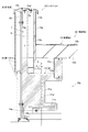
図1において符号1は、第一接続部材を示す。この第一接続部材1は、例えば建物躯体やその他の構造部分を構成する梁11(21,31)に対して、被支持部材である壁パネル14(24,34)を取り付けるために、これら梁11(21,31)と壁パネル14(24,34)との間に介在して、これら梁11(21,31)と壁パネル14(24,34)とを接続(または連結)するものである。
このような第一接続部材1は、梁11(21,31)に固定される固定部2と、固定部2に取り付けられるとともに壁パネル14(24,34)に沿って配置され、壁パネル14(24,34)が取り付けられる被取付部5と、を備える。
[Configuration of the first connecting member 1]
In FIG. 1, the code |
Such a first connecting
固定部2は、固定部本体3と、延長手段である張出用付属パーツ4と、を有する。
この固定部2の下面部2a(すなわち、固定部本体3と張出用付属パーツ4を含む固定部2の下端面全面)が、固定部2を梁11の位置に対して屋外側に張り出させて配置することを可能とする張出手段とされている。
下面部2aは梁11の上面に接しており、固定部2は、この下面部2aを梁11の上面に接触させた状態で、梁11の上面に沿ってスライド移動させられて位置が調整され、固定位置が確定した後に梁11の上面に固定される。これによって、固定部2と被取付部5とを含む第一接続部材1の位置調整および設置固定を行うことができる。固定部2を、梁11の位置に対して屋外側に張り出させた場合は、下面部2aのうち、固定部2を梁11に固定し得る面積の部位が梁11の上面に接している。
なお、本実施形態における固定部2は、梁11に対して、溶接やボルト留め等によって接合されて固定されている。
The fixing
The lower surface portion 2a of the fixing portion 2 (that is, the entire lower end surface of the fixing
The lower surface portion 2 a is in contact with the upper surface of the
In addition, the fixing |
固定部本体3は、第一接続部材1における被取付部5が取り付けられるとともに梁11に固定されるものであり、図1に示すように角筒状に形成されている。すなわち、被取付部5が取り付けられる上面と、梁11に固定される下面と、屋外側に位置する側面と、屋根面12側に位置する側面(内側スペース側に位置する側面)と、を備えた状態となっている。
なお、この固定部本体3は、単体で用いられてもよいし、複数で用いられてもよいものとする。固定部本体3の長さは、単体で用いられる場合には梁11の長さに合わせて適宜変更可能であり、複数で用いられる場合には後述する長尺部6よりも短く設定される。
The fixed portion
In addition, this fixing | fixed part
張出用付属パーツ4は、固定部本体3に対して、固定部2の屋外への張出寸法を延長させるための延長手段として必要に応じて取り付けられるものである。そのため、張出用付属パーツ4が必要ではない場合には、固定部本体3のみが用いられる(図3参照)。また、張出用付属パーツ4が必要な場合には、梁11に固定されて固定部本体3を外部側に張り出して配置することが可能となる(図2,4参照)。この場合、固定部本体3は梁11に固定されない。
さらに、この張出用付属パーツ4は、梁11に対する壁パネル14の位置(互いの離間寸法)に応じて、適宜長さ調整されるものである。換言すれば、張出用付属パーツ4による固定部本体3の張り出し位置を、張出用付属パーツ4の長さに応じて調整することができる。
この張出用付属パーツ4は、図1に示すように断面L型のアングル材であり、梁11に固定される下面板部4aを備えた状態となっている。この下面板部4aの下面は、固定部本体3の下面と面一になっている。
また、張出用付属パーツ4は、固定部本体3に対して複数設けられており、これら複数の張出用付属パーツ4は、互いに間隔をあけて配置されている。
The
Further, the length of the overhanging
As shown in FIG. 1, the overhanging
A plurality of overhanging
被取付部5は、長尺部6と、鉛直部である複数の柱状部7と、係合部8と、を有する。
長尺部6は、固定部2に取り付けられるものであり、梁11の長さ方向に沿って長尺に形成されている。また、この長尺部6としては溝形鋼が採用されており、ウェブと上下のフランジを備え、開放部分が屋外側を向くようにして固定部2に取り付けられている。
複数の柱状部7は、長尺部6の上フランジに対して取り付けられるものであり、長尺部6の上フランジの長さ方向に間隔を空けて取り付けられている。また、複数の柱状部7は、図1に示すように角筒状に形成されている。
そして、これら複数の柱状部7は、壁パネル14の高さに応じて高さ調整されている。つまり、個別の住宅ごとに壁パネル14の高さはそれぞれ異なる場合があるが、これら複数の柱状部7の高さ調整を行うことで、個別の住宅ごとに壁パネル14の高さが違っていても確実に対応することができる。
係合部8は、複数の柱状部7の上端面に取り付けられるとともに壁パネル14側に設けられた被係合部14aに係合するものである。この係合部8は、複数の柱状部7の上端面から壁パネル14側に突出するとともに、角筒状に形成された複数の柱状部7の上端部をキャップする上面板部8aと、この上面板部8aの突出方向側端部から壁パネル14の裏面に沿って下垂する下垂板部8bと、を備える。そして、この係合部8における下垂板部8bが、被係合部14aに係合している。
The attached
The
The plurality of
The plurality of
The engaging
なお、本実施形態における第一接続部材1は金属製であり、各部位同士は、例えば溶接やボルト・ナット等により接合固定されているものとする。
In addition, the
〔図2に示す実施形態の説明〕
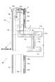
図2には、以上のような第一接続部材1が適用された状態の、住宅等の建物における陸屋根10の構成が示されている。
この陸屋根10は、建物躯体の最上端に位置する梁11がその構造の要となるように構成されており、梁11は、陸屋根10における小屋裏空間10aに位置した状態となっている。
陸屋根10の屋根面12は、例えばALC(autoclaved lightweight concrete)パネルを始めとするコンクリート製の屋根面材12aと、屋根面材12aの上面を被覆する防水シート12bと、によって構成されている。
また、屋根面12の外周縁には、屋根面12よりも上方に立ち上がるパラペット13が設けられている。
[Description of Embodiment shown in FIG. 2]
FIG. 2 shows the structure of the flat roof 10 in a building such as a house in a state where the first connecting
The flat roof 10 is configured such that a
The roof surface 12 of the land roof 10 is composed of a concrete
Further, a parapet 13 that rises above the roof surface 12 is provided on the outer peripheral edge of the roof surface 12.
梁11としては、ウェブ11aと、上下のフランジ11b,11cを備えた所謂H型鋼が採用されている。
梁11における上フランジ11bには、屋根面材12aが載せられて支持される支持フレーム12cが、例えば溶接等により接合固定されている。支持フレーム12cは、図示しない位置に複数設けられており、これら複数の支持フレーム12cによって屋根面材12aを支持した状態となっている。
なお、梁11の周囲には、耐火被覆材11dが、梁11全体を被覆するようにして設けられている。耐火被覆材11dは、梁11に接合された支持フレーム12cの周囲にも設けられている。
As the
A
A
パラペット13は、第一接続部材1と、壁パネル14と、下地板材13aと、防水シート13bと、笠木13cと、によって構成されている。
下地板材13aは、第一接続部材1の屋根面12側に位置しており、その表面に防水シート13bが貼り付けられている。この防水シート13bは、屋根面材12aの上面を被覆する防水シート12bにおけるパラペット13側縁部に対して上から重ね合わせられており、屋根面12とパラペット13との境界部分における水密性を確保している。
なお、この下地板材13aは、耐火性能を有する壁面材であり、屋根面材12aと接した状態となっている。
The parapet 13 includes the first connecting
The
In addition, this
壁パネル14は、第一接続部材1の屋外側に位置し、耐火性能を有する外壁パネルであり、第一接続部材1によって梁11と接続し合う状態となる。この壁パネル14は、ある程度の厚みがあり、当該壁パネル14を上下方向に貫通する空洞部が複数形成されている。これら複数の空洞部同士は、壁パネル14の幅方向に並んで配置されている。
なお、本実施形態において壁パネル14は、上下に重なるようにして複数設けられている。下側に位置する壁パネル14は、図示しない位置で建物躯体に取り付けられた支持材14bによって支持されている。
より詳細に説明すると、上下に重なる複数の壁パネルからなる壁パネル14は、その裏面における上端部と下端部のそれぞれに被係合部14aが取り付けられている。そして、上端部の被係合部14aに対しては複数の柱状部7の上端面に取り付けられた係合部8が係合し、下端部の被係合部14aに対しては支持材14bが係合する。
なお、これら上下の被係合部14aは、角度の緩い略S型に形成されるとともに、ボルトによって壁パネル14の裏面に固定されている。ボルトは、壁パネル14に形成された空洞部を利用することで、壁パネル14に対して留め付けが可能となっており、ボルトの先端が空洞部内に納まるようになっている。そして、ボルトの締め付けによって、被係合部14aと壁パネル14の裏面との間に、被係合部14aに係合する係合部8および支持材14bを挟持した状態とすることができる。
The wall panel 14 is an outer wall panel that is located on the outdoor side of the first connecting
In the present embodiment, a plurality of wall panels 14 are provided so as to overlap each other. The wall panel 14 located on the lower side is supported by a
More specifically, the wall panel 14 composed of a plurality of wall panels that are vertically stacked has an engaged
The upper and lower
笠木13cは、パラペット13の上端部に設けられるものであり、第一接続部材1、壁パネル14、下地板材13aおよび防水シート13bの上端部に覆い被さるようにして設けられている。
なお、この笠木13cは、第一接続部材1における係合部8の上面板部8aに対して取り付けられた笠木受け13dを介して第一接続部材1に固定されている。
The
The
以上のような陸屋根10を構成する上で、第一接続部材1は、梁11と壁パネル14との間に介在して、これら梁11と壁パネル14とを接続している。
より詳細に説明すると、固定部2における固定部本体3および張出用付属パーツ4が、梁11における上フランジ11bの上面に固定されている。固定部本体3は、梁11の上フランジ11bにおける屋外側縁部よりも屋外側に若干はみ出して設けられている。
被取付部5は、屋外側にはみ出した固定部本体3の上に取り付けられた状態となっており、複数の柱状部7が、屋根面12よりも上方に突出した状態となっている。これら複数の柱状部7には係合部8が取り付けられており、係合部8が、壁パネル14の被係合部14aに係合している。これにより、第一接続部材1を介して梁11と壁パネル14とを接続することができる。
In configuring the above-described flat roof 10, the first connecting
If it demonstrates in detail, the fixing | fixed part
The attached
〔図3に示す実施形態の説明〕
図3には、上述の第一接続部材1が適用された状態の、住宅等の建物における陸屋根20の構成が示されている。
この陸屋根20は、上述した図2に示す陸屋根10と略同様の構成となっている。これら陸屋根10と陸屋根20との大きな相違点としては、第一接続部材1における張出用付属パーツ4が用いられていない点と、複数の柱状部7の高さ寸法が短い点と、が挙げられる。
すなわち、陸屋根10と陸屋根20は、それぞれ別の建物の屋根である。または、同一の建物における陸屋根の別々の場所であってもよい。
[Description of Embodiment shown in FIG. 3]
FIG. 3 shows a configuration of the flat roof 20 in a building such as a house in a state where the
This flat roof 20 has substantially the same configuration as the flat roof 10 shown in FIG. 2 described above. The major differences between the flat roof 10 and the flat roof 20 are that the
That is, the land roof 10 and the land roof 20 are roofs of different buildings. Or it may be a separate place on a flat roof in the same building.
陸屋根20について、より詳細に説明すると、建物躯体の最上端に位置する梁21が、陸屋根20における小屋裏空間20aに位置した状態となっている。
陸屋根20の屋根面22は、屋根面材22aと、防水シート22bと、によって構成されている。また、屋根面22の外周縁にはパラペット23が設けられている。
The land roof 20 will be described in more detail. The
The
梁21としては、ウェブ21aと、上下のフランジ21b,21cを備えた所謂H型鋼が採用されている。
梁21における上フランジ21bには、屋根面材22a支持用の支持フレーム22cが接合固定されている。支持フレーム22cは、図示しない位置に複数設けられている。
なお、梁21および支持フレーム22cの周囲には、耐火被覆材21dが設けられている。
As the
A
A
パラペット23は、第一接続部材1と、壁パネル24と、第一接続部材1の屋根面22側に位置する下地板材23aと、この下地板材23aの表面に貼り付けられた防水シート23bと、笠木23cと、によって構成されている。
The
壁パネル24は、第一接続部材1の屋外側に位置する外壁パネルであり、第一接続部材1によって梁21と接続し合う状態となる。すなわち、壁パネル24は、その裏面における上端部と下端部のそれぞれに被係合部24aが取り付けられている。そして、上端部の被係合部24aに対しては複数の柱状部7の上端面に取り付けられた係合部8が係合し、下端部の被係合部24aに対しては、建物躯体に取り付けられた支持材(図示せず)が係合する。
The wall panel 24 is an outer wall panel located on the outdoor side of the
笠木23cは、パラペット23の上端部に設けられるものであり、第一接続部材1、壁パネル24、下地板材23aおよび防水シート23bの上端部に覆い被さるようにして設けられている。
なお、この笠木23cは、第一接続部材1における係合部8の上面板部8aに対して取り付けられた笠木受け23dを介して第一接続部材1に固定されている。
The
The
以上のような陸屋根20を構成する上で、第一接続部材1は、梁21と壁パネル24との間に介在して、これら梁21と壁パネル24とを接続している。
より詳細に説明すると、固定部2における固定部本体3が、梁21における上フランジ21bの上面に固定されている。固定部本体3は、梁21の上フランジ21bにおける屋外側縁部よりも屋外側にはみ出さないように設けられている。
被取付部5は、固定部本体3の上に取り付けられており、複数の柱状部7が、屋根面22よりも上方に突出した状態となっている。これら複数の柱状部7には係合部8が取り付けられており、係合部8が、壁パネル24の被係合部24aに係合している。
これにより、第一接続部材1を介して梁21と壁パネル24とを接続することができる。また、図3に示す陸屋根20は、図2に示す陸屋根10と比較すると、パラペット23の位置が屋内側に位置した状態となっており、さらにパラペット23の高さが低くなっている。
In configuring the above-described flat roof 20, the first connecting
If it demonstrates in detail, the fixing | fixed part
The attached
Thereby, the
〔図4に示す実施形態の説明〕
図4には、上述の第一接続部材1が適用された状態の、屋外用目隠し壁30の構成が示されている。
屋外用目隠し壁30は、例えば住宅等の建物の屋上に立設されており、屋外用目隠し壁30の内側は、洗濯物を干す場所として利用したり、その他のプライベート空間として利用したりすることができる。そして、この屋外用目隠し壁30によって外側からの視線を遮ることができる。なお、屋外用目隠し壁30の内側スペースは、上部が開放された露天の状態となっており、屋内空間から行き来することができる。
[Description of Embodiment shown in FIG. 4]
FIG. 4 shows a configuration of the outdoor blindfold wall 30 in a state where the
The outdoor blindfold wall 30 is erected on the roof of a building such as a house, for example, and the inside of the outdoor blindfold wall 30 is used as a place for washing laundry or other private space. Can do. Then, the line of sight from the outside can be blocked by the outdoor blindfold wall 30. In addition, the inside space of the outdoor blindfold wall 30 is in an open-air state with an open top, and can be moved from the indoor space.
屋外用目隠し壁30は、建物躯体の梁31を含んで構成されている。そして、屋外用目隠し壁30は、概略的に、梁31よりも下方に位置する部位32と、上方に位置する部位33に分かれて構成されている。特に、内側スペースから見た場合に、梁31は、屋外用目隠し壁30における突出部位として設けられ、この梁31を境にして上下に分けられたような状態となっている。例えば梁31の直上と直下に、当該梁31を含んで屋外用目隠し壁30を形成した場合、この屋外用目隠し壁30は、図4に示す状態よりも内側スペースに寄せて配置されることになる。つまり、屋外用目隠し壁30が寄った分、内側スペースが狭くなるため、屋外用目隠し壁30は、図4に示すように梁31よりも屋外側にあるような状態で設けられている。
なお、梁31としては、ウェブ31aと、上下のフランジ31b,31cを備えた所謂H型鋼が採用されている。梁31の周囲には耐火被覆材31dが設けられており、耐火被覆材31dによって被覆された梁31は、さらに梁カバー材31eによってカバーされている。梁カバー材31eの上面には水勾配が形成されている。
The outdoor blindfold wall 30 includes a
As the
梁31よりも下方に位置する部位32は、屋外側に向けられた壁パネル34と、内側スペース側に向けられた壁パネル32aと、複数の胴縁32bと、壁パネル34に平行して立設された柱32cと、によって構成されている。
内側の壁パネル32aは、耐火性能を有する外壁パネルであり、複数の胴縁32bを介して、柱32cに取り付けられている。なお、柱32cは、屋外用目隠し壁30の幅方向に間隔をあけて複数設けられており、これら複数の柱32cに対して壁パネル32aが取り付けられている。
また、梁カバー材31eの下端部は、柱32cと、胴縁32bとの間に挟み込まれるようにして、柱32cに固定されているものとする。
A
The
The lower end portion of the
梁31よりも上方に位置する部位33は、上述した陸屋根10,20におけるパラペット13,23と同様に、第一接続部材1を含んで構成されている。
すなわち、当該梁31よりも上方に位置する部位33は、第一接続部材1と、屋外側に向けられた壁パネル34と、内側スペース側に向けられた壁パネル33aと、複数の胴縁33bと、笠木33cと、によって構成されている。
内側の壁パネル33aは、耐火性能を有する外壁パネルであり、複数の胴縁33bを介して、第一接続部材1における複数の柱状部7の内側スペース側に取り付けられている。なお、梁カバー材31eの上端部は、第一接続部材1における長尺部6のウェブに固定されており、内側スペース側の壁パネル33aによって覆われている。
The
That is, the
The
第一接続部材1には張出用付属パーツ4が用いられており、図4に示す例において固定部本体3は、梁31の上フランジ31bには固定されない。
張出用付属パーツ4の長さは、図2に示す例における張出用付属パーツ4の長さよりも長く設定されており、被取付部5を、梁31から、より一層離間させることができる。
また、複数の柱状部7の長さは、図1に示す例における複数の柱状部7の長さよりも短く設定されている。
The overhanging
The length of the overhanging
Moreover, the length of the some
梁31よりも下方に位置する部位32と、上方に位置する部位33における壁パネル34は、耐火性能を有する外壁パネルであり、屋外用目隠し壁30の屋外側壁面を構成している。そして、この壁パネル34は、柱32cおよび第一接続部材1の屋外側に位置し、第一接続部材1によって梁31と接続し合う状態となる。この壁パネル34は、ある程度の厚みがあり、当該壁パネル34を上下方向に貫通する空洞部が複数形成されている。これら複数の空洞部同士は、壁パネル34の幅方向に並んで配置されている。
なお、本実施形態において壁パネル34は、梁31よりも下方に位置する部位32側と、上方に位置する部位33側に分かれているが、一枚の壁パネル34を採用してもよい。梁31よりも下方に位置する部位32側と、上方に位置する部位33側に分かれた箇所の目地には目地材が充填されている。また、下側に位置する壁パネル34は、梁31よりも下方に位置する部位32における壁パネル34であり、図示しない位置で建物躯体に取り付けられた支持材によって支持されている。
The
In the present embodiment, the
壁パネル34は、その裏面における上端部と下端部のそれぞれに被係合部34aが取り付けられている。そして、上端部の被係合部34aに対しては複数の柱状部7の上端面に取り付けられた係合部8が係合し、下端部の被係合部(図示せず)に対しては、建物躯体に取り付けられた支持材(図示せず)が係合する。
As for the
笠木33cは、梁31よりも上方に位置する部位33の上端部に設けられるものであり、第一接続部材1、屋外側の壁パネル34、内側スペース側の壁パネル33aの上端部に覆い被さるようにして設けられている。
なお、この笠木33cは、第一接続部材1における係合部8の上面板部8aに対して取り付けられた笠木受け33dを介して第一接続部材1に固定されている。
The
The
以上のような屋外用目隠し壁30を構成する上で、第一接続部材1は、梁31と壁パネル34との間に介在して、これら梁31と壁パネル34とを接続している。
より詳細に説明すると、固定部2における張出用付属パーツ4が、梁31における上フランジ11bの上面に固定されている。固定部本体3は、梁31の上フランジ31bにおける屋外側縁部から屋外側に離間した位置に設けられている。
被取付部5は、屋外側に離間した固定部本体3の上に取り付けられた状態となっており、複数の柱状部7が、梁カバー材31eの上面よりも上方に突出した状態となっている。これら複数の柱状部7には係合部8が取り付けられており、係合部8が、壁パネル34の被係合部34aに係合している。これにより、第一接続部材1を介して梁11と壁パネル34とを接続することができる。
また、複数の柱状部7は、梁31よりも下方に位置する部位32を構成する柱32cの上方に、かつ同一鉛直面上に配置されている。これにより、梁31よりも下方に位置する部位32における壁パネル32aの内側スペース側の表面と、梁31よりも上方に位置する部位33における壁パネル33aの内側スペース側の表面と、が同一鉛直面上に配置された状態となっている。
In configuring the outdoor blindfold wall 30 as described above, the first connecting
More specifically, the overhanging
The to-
In addition, the plurality of
〔図5に示す実施形態の説明〕
図5に示す第一接続部材1は、固定部2が、梁の長さ方向に間隔を空けて配置される複数の固定部本体3(一方の固定部本体3a、他方の固定部本体3b)を有しており、被取付部5における長尺部6が、これら複数の固定部本体3a,3b間に架け渡された状態に構成されている。換言すれば、複数の固定部本体3a,3bが、この長尺部6を介して接続された状態となっている。
このような第一接続部材1は、梁11と他の梁11Aとが互いに長さ方向に沿って隣接して設けられ、これら梁11と他の梁11Aの上面間に接合プレート15が跨ってそれぞれに固定されている場合に採用されている。
[Description of Embodiment shown in FIG. 5]
The
In such a
接合プレート15は所謂スプライスプレートであり、図示はしないが、梁11と他の梁11Aにおける上フランジ11b同士の上面だけでなく下面にも設けられ、ボルト・ナットによって接合されている。このような接合プレート15は、上フランジ11bだけでなく、ウェブ11aの表裏面や下フランジ11cの上下面にも同様に設けられている。
すなわち、梁11と他の梁11Aとが長さ方向に隣接して設けられる場合、その接合箇所は、複数の接合プレート15によって囲まれて固定された状態となる。
The joining
That is, when the
図5に示す第一接続部材1は、複数の固定部本体3a,3bが、接合プレート15を挟んで梁11側と他の梁11A側に配置されている。そして、長尺部6が、接合プレート15の上方を跨ぐようにして複数の固定部本体3a,3b間に架け渡されている。
すなわち、複数の固定部本体3a,3b間の間隔の長さは、少なくとも接合プレート15よりも長く設定されている。
In the
That is, the length of the interval between the plurality of fixed portion
そして、このように第一接続部材1は、梁11および梁11Aと、壁パネル14との間に介在して、これら梁11,11Aと壁パネル14とを接続している。
より詳細に説明すると、固定部2における複数の固定部本体3a,3bおよび各々の張出用付属パーツ4が、梁11,11Aにおける上フランジ11bの上面に固定されている。複数の固定部本体3a,3bは、梁11の上フランジ11bにおける屋外側縁部よりも屋外側に若干はみ出して設けられている。被取付部5は、屋外側にはみ出した固定部本体3の上に取り付けられた状態となっている。これにより、第一接続部材1を介して梁11,11Aと壁パネル14とを接続することができる。
In this way, the first connecting
More specifically, the plurality of fixing portion
第一接続部材1が用いられた本実施の形態によれば、梁11(21,31)に固定される固定部2が、被取付部5が取り付けられるとともに梁11(21,31)に固定される固定部本体3(3a,3b)と、固定部本体3(3a,3b)に対して必要に応じて取り付けられた場合に、固定部本体3(3a,3b)に代わって梁11(21,31)に固定されて固定部本体3(3a,3b)を外部側に張り出して配置することが可能な張出用付属パーツ4と、を有するので、固定部本体3(3a,3b)を梁11(21,31)に固定するか、張出用付属パーツ4を梁11(21,31)に固定するか、または双方を梁11(21,31)に固定するか、を個別の建物構造に応じて選択できる。また、張出用付属パーツ4の長さ次第で、固定部本体3(3a,3b)の張り出し位置を調節することもできる。したがって、梁11(21,31)の位置に対する壁パネル14(24,34)の外部側への出寸法が個別の建物ごとに異なるものであっても柔軟に対応することができる。
さらに、固定部2に取り付けられるとともに壁パネル14(24,34)に沿って配置され、壁パネル14(24,34)が取り付けられる被取付部5が、固定部2に取り付けられるとともに梁11(21,31)の長さ方向に沿って長尺に形成された長尺部6と、長尺部6に対し、壁パネル14(24,34)の高さに応じて高さ調整された状態で、かつ長尺部6の長さ方向に間隔を空けて取り付けられる複数の柱状部7と、を有するので、壁パネル14(24,34)の高さ(上下寸法)に合わせて複数の柱状部7の高さ調整を行った上で、これら複数の柱状部7を長尺部6に取り付けることができる。したがって、梁11(21,31)の位置よりも上方に突出する分の壁パネル14(24,34)の高さ寸法が個別の建物ごとに異なるものであっても柔軟に対応することができる。
そして、このように梁11(21,31)に対する壁パネル14(24,34)の位置が個別の建物ごとに異なる場合であっても梁11(21,31)と壁パネル14(24,34)とを確実に接続できるので、個別の建物ごとに部材全体の寸法設定を変更する必要が無く、施工手間やコストを軽減できる。
しかも、梁11(21,31)に対する壁パネル14(24,34)の位置が個別の建物ごとに異なる状態は、パラペットを構成する壁パネルや、部屋を構成する壁パネルなど、建物の様々な箇所で生じ得るが、基本構成はそのままに、張出用付属パーツ4の使用・不使用を個別の建物ごとに選択したり、複数の柱状部7の長短を個別の建物ごとに設定したりするだけで、個別の建物ごとに柔軟に対応できるので、汎用性に優れる。
According to the present embodiment in which the
Further, the attached
And even if it is a case where the position of the wall panel 14 (24, 34) with respect to the beam 11 (21, 31) differs for every individual building in this way, the beam 11 (21, 31) and the wall panel 14 (24, 34). ) Can be reliably connected, so that it is not necessary to change the dimension setting of the entire member for each individual building, and construction labor and cost can be reduced.
In addition, the state in which the position of the wall panel 14 (24, 34) with respect to the beam 11 (21, 31) differs for each individual building includes various building structures such as a wall panel constituting a parapet and a wall panel constituting a room. Although it may occur in some places, the use of the
また、被取付部5は、複数の柱状部7に取り付けられるとともに壁パネル14(24,34)側に設けられた被係合部14a(24a,34a)に係合する係合部8を有するので、係合部8を、壁パネル14(24,34)側の被係合部14a(24a,34a)に係合させることで、壁パネル14(24,34)を被取付部5に確実に取り付けることができる。
The attached
また、固定部2における固定部本体3(3a,3b)と張出用付属パーツ4のうち、少なくともいずれか一方が梁11(21,31)に固定されているので、固定部本体3(3a,3b)を梁11(21,31)に固定するか、張出用付属パーツ4を梁11(21,31)に固定するか、または双方を梁11(21,31)に固定するか、を選択して、第一接続部材1を梁11(21,31)に設置することができる。そのため、梁11(21,31)の位置に対する壁パネル14(24,34)の外部側への出寸法が個別の建物ごとに異なるものであっても、第一接続部材1によって梁11(21,31)と壁パネル14(24,34)とを確実に接続することができる。
Further, since at least one of the fixing part main body 3 (3a, 3b) and the overhanging
また、固定部2は、梁11の長さ方向に間隔を空けて配置される複数の固定部本体3(3a,3b)を有しており、被取付部5における長尺部6は、複数の固定部本体3(3a,3b)間に架け渡されているので、固定部本体3(3a,3b)の長さを長尺部6に合わせて長くする必要がなく、コストの軽減を図ることができる。
さらに、固定部2が固定される梁に、例えば梁11,11A同士の接合箇所に生じる出っ張り(例えば接合プレート15)がある場合や、その他の障害物がある場合に、当該障害物を挟み込む位置に複数の固定部本体3(3a,3b)を配置して、当該障害物を跨ぐようにして長尺部6を配置できる。そのため、梁11に障害物がある場合でも、第一接続部材1によって梁11と壁パネル14とを確実に接続できる。
Moreover, the fixing |
Furthermore, the position where the obstacle is sandwiched when the beam to which the fixing
また、梁11に隣接して他の梁11Aが設けられており、梁11と他の梁11Aは、互いに長さ方向に沿って隣接するように配置され、当該梁11と他の梁11Aの上面間に接合プレート15が跨ってそれぞれに固定されていることによって接合されているので、梁11と他の梁11Aとの接合箇所における上面に、接合プレート15の分の出っ張りが生じることになる。そして、複数の固定部本体3a,3bが、接合箇所における出っ張りとなる接合プレート15を挟んで梁11側と他の梁11A側に配置されているので、当該接合プレート15を跨ぐようにして長尺部6を配置できる。そのため、梁11と他の梁11Aとの接合箇所であっても、第一接続部材1によって梁11と壁パネル14とを確実に接続できる。
Further, another
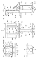
〔第二接続部材の構成〕
図6〜図8において符号41は、第二接続部材を示す。この第二接続部材41は、例えば建物躯体やその他の構造部分を構成する梁51に対して、被支持部材である手摺支柱54を取り付けるために、これら梁51と手摺支柱54との間に介在して、これら梁51と手摺支柱54とを接続(または連結)するものである。
このような第二接続部材41は、梁51に固定される固定部42と、固定部42に取り付けられるとともに手摺支柱54に沿って配置され、手摺支柱54が取り付けられる被取付部45と、を備える。
そして、固定部42は、当該固定部42を梁51の位置に対して屋外側に張り出させて配置することを可能とする張出手段を含んで構成され、被取付部45は、手摺支柱54の高さに応じて高さ調整された状態の、鉛直部である立ち上がり部47を有する。
なお、図7(a)は図6におけるA−A線断面図であり、図7(b)は図7(a)におけるB矢視図であり、図7(c)は図7(b)におけるC矢視図であり、図7(d)は図7(b)におけるD−D線断面図である。ただし、図7(c),(d)においてボルト・ナットは省略している。
[Configuration of second connecting member]
6-8, the code | symbol 41 shows a 2nd connection member. The second connection member 41 is interposed between the
Such a second connecting member 41 includes a fixed
And the fixing | fixed
7A is a cross-sectional view taken along line AA in FIG. 6, FIG. 7B is a view taken in the direction of arrow B in FIG. 7A, and FIG. 7C is FIG. 7B. FIG. 7D is a cross-sectional view taken along line DD in FIG. 7B. However, bolts and nuts are omitted in FIGS. 7 (c) and 7 (d).
固定部42は、固定部本体43と、延長手段である延長部44と、を有する。
この固定部42の下面部42a(すなわち、固定部本体43と延長部44を含む固定部42の下端面全面)が、固定部42を梁51の位置に対して屋外側に張り出させて配置することを可能とする張出手段とされている。
下面部42aは梁51の上面に接しており、固定部42は、この下面部42aを梁51の上面に接触させた状態で、梁51の上面に沿ってスライド移動させられて位置が調整され、固定位置が確定した後に梁51の上面に固定される。これによって、固定部42と被取付部45とを含む第二接続部材41の位置調整および設置固定を行うことができる。固定部42を、梁51の位置に対して屋外側に張り出させた場合は、下面部42aのうち、固定部42を梁51に固定し得る面積の部位が梁51の上面に接している。
なお、本実施形態における固定部42は、梁51に対して、ボルト留めによって接合されて固定されている。
The fixing
The lower surface portion 42 a of the fixing portion 42 (that is, the entire lower end surface of the fixing
The lower surface portion 42a is in contact with the upper surface of the
In addition, the fixing | fixed
また、固定部42は、固定部本体43と延長部44とを含んでプレート状に形成されている。換言すれば、固定部本体43と延長部44は一体形成されて一枚のプレートとして形成された状態となっている。このように一枚のプレートとして形成されたものが、本実施形態における固定部42とされている。
固定部本体43は、第二接続部材41の被取付部45が取り付けられるとともに梁51に固定されるものである。ただし、この固定部本体43が、梁51の位置に対して屋外側に張り出した位置に配置される場合には、固定部本体43に代わって延長部44が梁51に固定される。
The fixing
The fixed portion
延長部44は、補剛部44aと、範囲規制部である長孔部44bと、を有する。
補剛部44aは、延長部44と被取付部45との間に設けられた板状体であり、第二接続部材41自体の剛性を高めることができる。なお、本実施形態においては2枚の補剛部44aが用いられている。
範囲規制部である長孔部44bは、延長部44に対して、屋外とその反対方向(梁51の長さ方向と直交する方向)に長くなるように形成されている。この長孔部44bには、ボルト44cが通される。これに対応して、梁51の上フランジ51bにもボルト44cが通される通孔51dが形成されており、双方に通されたボルト44cにナット44dを締め付けることで、固定部42を梁51に固定することができる。また、ナット44dを締め付ける前に、長孔部44bに沿って固定部42の張出位置を調整することができる。さらに、固定部42を張り出させる際の移動範囲を長孔部44bによって規制できる。
なお、本実施形態において、長孔部44bは、延長部44に対して2箇所に形成されており、梁51の上フランジ51bに形成された通孔51dもこれに対応している。
The
The stiffening
The
In the present embodiment, the
被取付部45は、長尺部として機能する通しアングル材46と、鉛直部である立ち上がり部47と、係合部48と、を有する。
通しアングル材46は、梁51の長さ方向に間隔を空けて隣り合う複数の立ち上がり部47,47の上端部間に架け渡されるようにして設けられるものである。
立ち上がり部47は、固定部本体43に取り付けられており、図7に示すように、断面略コ字状に形成されている。すなわち、この立ち上がり部47には、いわゆる溝形鋼状の部材が採用されており、ウェブと上フランジ47aと下フランジを備える。立ち上がり部47における下フランジが固定部本体43に接合固定されている。
この立ち上がり部47の上フランジ47aと通しアングル材46は互いに平行に配置され、かつスチフナ47b(本実施形態では、1つの立ち上がり部47につき2枚のスチフナが用いられる)を介して連結された状態となっている。これにより、通しアングル材46と立ち上がり部47とを含む被取付部45は側面視(側断面視)において略逆L字状に形成された状態となっている。
立ち上がり部47は、手摺支柱54の高さに応じて高さ調整されている。また、通しアングル材46の高さ位置も立ち上がり部47の高さに対応している。つまり、個別の住宅ごとに手摺支柱54を含む手摺壁の高さはそれぞれ異なる場合があるが、立ち上がり部47の高さ調整を行うことで、個別の住宅ごとに手摺壁の高さが違っていても確実に対応することができる。
なお、立ち上がり部47の上フランジ47aにおける裏面(下面)と、通しアングル材46の裏面に跨って、裏当てプレート47cが設けられており、スチフナ47bと共に、立ち上がり部47の上フランジ47aと通しアングル材46とを連結している。
係合部48は、立ち上がり部47の上フランジ47aおよび通しアングル材46に設けられるとともに、手摺支柱54側に設けられた被係合部55aに係合するものである。
この係合部48は、立ち上がり部47の上フランジ47aおよび通しアングル材46に形成された通孔に上方から下方に向かって通されるボルトと、このボルトを受ける袋ナットと、を有する。
The attached
The through-
The rising
The
The rising
A
The engaging
The engaging
梁51の上面にはバルコニー50の床を構成する床パネル52aが設置され、梁51の長さ方向に間隔を空けて隣り合う立ち上がり部47,47間には、バルコニー1内側の壁を構成する内側壁材52bが設けられている。
内側壁材52bは、隣り合う立ち上がり部47,47間に架け渡されるようにして設けられた下端側板受部49aと側端側板受部49bに固定されている。
A
The
図8には、以上のような第二接続部材41が適用された状態の、住宅等の建物におけるバルコニー50の構成が示されている。
このバルコニー50は、建物躯体の梁51がその構造の要となるように構成されており、床が上述のような床パネル52aによって形成されている。また、この床の屋外側縁部に沿ってパラペット53が形成されている。
パラペット53の上には手摺支柱54が設けられ、パラペット53の屋外側には外壁となる壁パネル56が設けられている。壁パネル56は、図示しない位置で梁51やその他の建物躯体によって支持されている。
また、パラペット53の上端部は笠木53aによって被覆されている。すなわち、この笠木53aによって、立ち上がり部47の上端部や内側壁材52bの上端部、手摺支柱54の下端部、壁パネル56の上端部を被覆することができる。
なお、床パネル52aの上面から内側壁材52bの表面にかけて防水シートが貼り付けられている。
FIG. 8 shows the configuration of the balcony 50 in a building such as a house in a state where the second connecting member 41 as described above is applied.
The balcony 50 is configured such that the
A handrail support 54 is provided on the parapet 53, and a
Moreover, the upper end part of the parapet 53 is coat | covered with the
In addition, the waterproof sheet is affixed from the upper surface of the
手摺壁を構成する手摺支柱54は、支柱本体54aと、この支柱本体54aの下端部に設けられたプレート状のベース部55と、を備える。ベース部55は、各被取付部45における立ち上がり部47の上フランジ47aおよび通しアングル材46に設けられた係合部48に係合する被係合部55aを備える。
被係合部55aは、ベース部55に形成されたボルト通孔であり、上述した係合部48を構成するボルトが通されるようになっている。被係合部55aであるボルト通孔に通されたボルトを、立ち上がり部47の上フランジ47aおよび通しアングル材46に形成された通孔に通し、袋ナットに対して締め付けることによって、ベース部55を、立ち上がり部47の上フランジ47aおよび通しアングル材46に固定することができる。
なお、被係合部55aであるボルト通孔は、ベース部55の四隅近傍に形成されており、立ち上がり部47の上フランジ47aおよび通しアングル材46に形成された通孔の位置は、これに対応している。
The handrail support 54 constituting the handrail wall includes a support
The engaged
It should be noted that the bolt through holes, which are the engaged
以上のように、第二接続部材41は、バルコニー50を構成するに当たって、梁51と被支持部材である手摺支柱54との間に介在して、これら梁51と手摺支柱54とを接続している。
梁51の位置に対する手摺支柱54の屋外側への張出寸法が個別の建物ごとに異なる場合があるが、その場合は、範囲規制部である長孔部44bが形成された範囲内で、張出手段である固定部42の下面部42aに沿って第二接続部材41を位置調整する。
また、被取付部45は、屋外側にはみ出した固定部本体43の上に取り付けられた状態となっており、立ち上がり部47が、屋根面12よりも上方に突出した状態となっている。立ち上がり部47には係合部48が設けられており、係合部48が、手摺支柱54の被係合部55aに係合している。これにより、第二接続部材41を介して梁51と手摺支柱54とを接続することができる。
As described above, when configuring the balcony 50, the second connecting member 41 is interposed between the
The extension of the handrail post 54 to the outdoor side with respect to the position of the
The attached
また、図7,8に示すように、梁51と固定部42との間には、固定部42のうち梁51よりも屋外側に張り出した部位を下方から支持する補助支持部60が設けられている。
補助支持部60は、梁51の下フランジ51cに固定される支持部61と、支持部61の屋外側端部から上方に突出し、屋外側に張り出した固定部本体43を受ける受部62と、を有する。これにより、固定部42が屋外側に張り出した部位を、この補助支持部60によって確実に支持することができる。
支持部61はプレート状に形成されており、下面部が下フランジ51cの上面に接した状態となっている。そして、この支持部61には、固定部42の延長部44に形成された長孔部44bと略等しい長さの長孔部61aが形成されている。下フランジ51cには、ボルトを通すための通孔51eが形成されており、この通孔51eと支持部61の長孔部61aの双方にボルトを通してナットを締め付けることによって、支持部61を下フランジ51cに固定することができる。さらに、第二接続部材41の位置調整を行う際に、固定部42と共に補助支持部60も、固定部42と等しい範囲で移動させることができる。
なお、支持部61と受部62との間には、補助支持部60自体の剛性を高めるための補剛部63が設けられている。
Further, as shown in FIGS. 7 and 8, an
The
The
In addition, between the
第二接続部材41が用いられた本実施形態によれば、固定部42は、当該固定部42を梁51の位置に対して屋外側に張り出させて配置することを可能とする張出手段(下面部42a)を含んで構成されているので、この張出手段によって、固定部42の張出位置を調整することができる。したがって、梁51の位置に対する手摺支柱54の屋外側への張出寸法が個別の建物ごとに異なるものであっても柔軟に対応することができる。
さらに、被取付部45は、手摺支柱54の高さに応じて高さ調整された状態の立ち上がり部47を有するので、手摺支柱54の高さに合わせて被取付部45の高さ調整を行った状態とすることができる。したがって、梁51の位置よりも上方に突出する分の手摺支柱54の高さ寸法が個別の建物ごとに異なるものであっても柔軟に対応することができる。
そして、このように梁51に対する手摺支柱54の位置が個別の建物ごとに異なる場合であっても梁51と手摺支柱54とを確実に接続できるので、個別の建物ごとに部材全体の寸法設定を変更する必要が無く、施工手間やコストを軽減できる。
しかも、梁51に対する手摺支柱54の位置が個別の建物ごとに異なる状態は、例えばバルコニー50や陸屋根10等におけるパラペット部分や、内・外壁など、建物の様々な箇所で生じ得るが、基本構成はそのままに、固定部42の張出位置を調整したり、立ち上がり部47の長短を個別の建物ごとに設定したりするだけで、個別の建物ごとに柔軟に対応できるので、汎用性に優れる。
According to the present embodiment in which the second connection member 41 is used, the fixing
Furthermore, since the attached
And even if the position of the handrail post 54 with respect to the
Moreover, the state in which the position of the handrail post 54 with respect to the
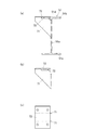
〔補助支持部の他の一例〕
図9に示す補助支持部70は、梁51に固定される支持部71と、図示しない被支持部材(例えば、手摺支柱54)を受ける受部72と、を備える。
支持部71は、プレート状に形成されており、一辺(側片)が梁51のウェブ51aに対して溶接等により接合固定されている。また、他片(上辺)の一部が受部72の下面に対して溶接等により接合されている。
受部72は、プレート状に形成されており、部分的に梁51の上面に載って接した状態となっている。この受部72の上面には被支持部材が取り付けられるため、ボルトを通すための複数の通孔が形成されている。
支持部71の他片のうち受部72と接合される部位(屋外側の部位)は、梁51における上フランジ51bの厚み分だけ上方に突出しており、受部72と接合されない部位(屋外側とは反対側の部位)と受部72との間には、梁51における上フランジ51bの厚み分だけ隙間73が形成された状態となっている。
補助支持部70を梁51に取り付ける場合は、梁51の上フランジ51bにおける屋外側縁部に、補助支持部70の隙間73を合致させて嵌め込み、その上で、支持部71の一片をウェブ51に接合固定する。このように取り付けられた補助支持部70における受部72の上面に被支持部材を載せて固定することによって、被支持部材を屋外側に張り出させた状態に配置できるとともに、被支持部材の屋外側に張り出した部位を確実に支持することができる。
[Another example of auxiliary support part]
The auxiliary support part 70 shown in FIG. 9 includes a
The
The receiving
Of the other piece of the
When the auxiliary support portion 70 is attached to the
1 第一接続部材
2 固定部
3 固定部本体
4 張出用付属パーツ
5 被取付部
6 長尺部
7 柱状部
8 係合部
10 陸屋根
11 梁
12 屋根面
13 パラペット
14 壁パネル
41 第二接続部材
42 固定部
43 固定部本体
44 延長部
45 被取付部
46 通しアングル材
47 立ち上がり部
48 係合部
50 バルコニー
51 梁
53 パラペット
54 手摺支柱
DESCRIPTION OF
Claims (7)
前記梁に固定される固定部と、
前記固定部に取り付けられるとともに前記被支持部材に沿って配置され、前記被支持部材が取り付けられる被取付部と、を備えており、
前記固定部は、当該固定部を前記梁の位置に対して屋外側に張り出させて配置することを可能とする張出手段を含んで構成され、
前記被取付部は、前記被支持部材の高さに応じて高さ調整された状態の鉛直部を有することを特徴とする接続部材。 A connecting member that is interposed between the beam and a supported member supported by the beam and connects the beam and the supported member;
A fixing portion fixed to the beam;
A fixed portion attached to the fixed portion and disposed along the supported member, to which the supported member is attached,
The fixing portion includes an extending means that allows the fixing portion to be arranged to protrude to the outdoor side with respect to the position of the beam,
The connecting member has a vertical part in a state where the height is adjusted according to the height of the supported member.
前記張出手段は前記固定部の下面部であり、
前記固定部は、前記張出手段である前記下面部に沿って屋外側への張出位置の調整が可能となっていることを特徴とする接続部材。 The connection member according to claim 1,
The overhanging means is a lower surface portion of the fixed portion;
The connecting member, wherein the fixing portion is capable of adjusting a protruding position to the outdoor side along the lower surface portion which is the protruding means.
前記固定部は、当該固定部の屋外への張出寸法を延長させるための延長手段を含んで構成されていることを特徴とする接続部材。 In the connection member according to claim 1 or 2,
The connecting member, wherein the fixing part includes an extending means for extending the dimension of the fixing part that projects to the outside.
前記固定部は、当該固定部が屋外に張り出す方向とその反対方向の移動範囲を規制する範囲規制部を有することを特徴とする接続部材。 In the connection member according to any one of claims 1 to 3,
The fixing member includes a range restricting portion that restricts a moving range in a direction opposite to a direction in which the fixing portion projects to the outdoors and the opposite direction.
前記被取付部は、前記鉛直部に設けられるとともに、前記被支持部材側に設けられた被係合部に係合する係合部を有することを特徴とする接続部材。 In the connecting member according to any one of claims 1 to 4,
The connecting member is provided with an engaging portion that is provided on the vertical portion and that engages with an engaged portion provided on the supported member side.
前記固定部は、
前記被取付部が取り付けられるとともに前記梁の長さ方向に間隔を空けて配置される複数の固定部本体を有しており、
前記被取付部は、
前記梁の長さ方向に沿って長尺に形成されて、前記複数の固定部本体同士を接続する長尺部と、
前記長尺部に対し、前記長尺部の長さ方向に間隔を空けて設けられた複数の前記鉛直部と、を有することを特徴とする接続部材。 In the connecting member according to any one of claims 1 to 5,
The fixing part is
The attached portion is attached and has a plurality of fixing portion main bodies arranged at intervals in the length direction of the beam,
The attached portion is
A long portion that is formed along the length direction of the beam and connects the plurality of fixed portion main bodies, and
A connecting member, comprising: a plurality of the vertical portions provided at intervals in the length direction of the long portion with respect to the long portion.
前記梁と前記固定部との間に設けられ、前記固定部のうち前記梁よりも屋外側に張り出した部位を下方から支持する補助支持部をさらに備えることを特徴とする接続部材。 In the connecting member according to any one of claims 1 to 6,
A connection member, further comprising an auxiliary support portion provided between the beam and the fixing portion, and supporting a portion of the fixing portion that projects outward from the beam from the lower side.
Priority Applications (1)
| Application Number | Priority Date | Filing Date | Title |
|---|---|---|---|
| JP2016186506A JP6795940B2 (en) | 2016-09-26 | 2016-09-26 | Connecting member |
Applications Claiming Priority (1)
| Application Number | Priority Date | Filing Date | Title |
|---|---|---|---|
| JP2016186506A JP6795940B2 (en) | 2016-09-26 | 2016-09-26 | Connecting member |
Publications (2)
| Publication Number | Publication Date |
|---|---|
| JP2018053424A true JP2018053424A (en) | 2018-04-05 |
| JP6795940B2 JP6795940B2 (en) | 2020-12-02 |
Family
ID=61835368
Family Applications (1)
| Application Number | Title | Priority Date | Filing Date |
|---|---|---|---|
| JP2016186506A Active JP6795940B2 (en) | 2016-09-26 | 2016-09-26 | Connecting member |
Country Status (1)
| Country | Link |
|---|---|
| JP (1) | JP6795940B2 (en) |
Cited By (1)
| Publication number | Priority date | Publication date | Assignee | Title |
|---|---|---|---|---|
| JP2021075937A (en) * | 2019-11-12 | 2021-05-20 | 積水ハウス株式会社 | Facility cradle structure, and building comprising the same |
Citations (10)
| Publication number | Priority date | Publication date | Assignee | Title |
|---|---|---|---|---|
| JPH034803U (en) * | 1989-06-01 | 1991-01-18 | ||
| JPH08218487A (en) * | 1995-02-10 | 1996-08-27 | Natl House Ind Co Ltd | Auxiliary structure |
| JPH10102719A (en) * | 1996-09-27 | 1998-04-21 | Sekisui House Ltd | Installation structure of handrail |
| JPH11343662A (en) * | 1998-06-01 | 1999-12-14 | Sekisui House Ltd | Mounting device of outer wall panel in balcony |
| JP2000045381A (en) * | 1998-07-30 | 2000-02-15 | Sekisui House Ltd | Mounting structure of exterior wall in balcony |
| JP2002235372A (en) * | 2001-02-08 | 2002-08-23 | Sekisui House Ltd | Exterior wall construction of balcony |
| JP2003027587A (en) * | 2001-07-16 | 2003-01-29 | Sekisui House Ltd | Pilot wall for house |
| JP3791745B2 (en) * | 1999-08-25 | 2006-06-28 | 積水ハウス株式会社 | Parapet waterproof structure |
| JP2013174095A (en) * | 2012-02-27 | 2013-09-05 | Toyota Home Kk | Wall drainage structure in building |
| JP2016118046A (en) * | 2014-12-22 | 2016-06-30 | ミサワホーム株式会社 | Attaching structure of exterior wall panel |
-
2016
- 2016-09-26 JP JP2016186506A patent/JP6795940B2/en active Active
Patent Citations (10)
| Publication number | Priority date | Publication date | Assignee | Title |
|---|---|---|---|---|
| JPH034803U (en) * | 1989-06-01 | 1991-01-18 | ||
| JPH08218487A (en) * | 1995-02-10 | 1996-08-27 | Natl House Ind Co Ltd | Auxiliary structure |
| JPH10102719A (en) * | 1996-09-27 | 1998-04-21 | Sekisui House Ltd | Installation structure of handrail |
| JPH11343662A (en) * | 1998-06-01 | 1999-12-14 | Sekisui House Ltd | Mounting device of outer wall panel in balcony |
| JP2000045381A (en) * | 1998-07-30 | 2000-02-15 | Sekisui House Ltd | Mounting structure of exterior wall in balcony |
| JP3791745B2 (en) * | 1999-08-25 | 2006-06-28 | 積水ハウス株式会社 | Parapet waterproof structure |
| JP2002235372A (en) * | 2001-02-08 | 2002-08-23 | Sekisui House Ltd | Exterior wall construction of balcony |
| JP2003027587A (en) * | 2001-07-16 | 2003-01-29 | Sekisui House Ltd | Pilot wall for house |
| JP2013174095A (en) * | 2012-02-27 | 2013-09-05 | Toyota Home Kk | Wall drainage structure in building |
| JP2016118046A (en) * | 2014-12-22 | 2016-06-30 | ミサワホーム株式会社 | Attaching structure of exterior wall panel |
Cited By (1)
| Publication number | Priority date | Publication date | Assignee | Title |
|---|---|---|---|---|
| JP2021075937A (en) * | 2019-11-12 | 2021-05-20 | 積水ハウス株式会社 | Facility cradle structure, and building comprising the same |
Also Published As
| Publication number | Publication date |
|---|---|
| JP6795940B2 (en) | 2020-12-02 |
Similar Documents
| Publication | Publication Date | Title |
|---|---|---|
| JP5564140B1 (en) | Roof panels and building roof structures | |
| JP2018053424A (en) | Connection member | |
| JP5461279B2 (en) | building | |
| JP5520002B2 (en) | Balcony and unit building with this | |
| JP5641632B1 (en) | Photovoltaic panel mounting bracket, roof panel, and roof structure | |
| JP5940293B2 (en) | Balconi floor structure | |
| JP7005870B2 (en) | Water stop structure of the building | |
| JP5103108B2 (en) | Balcony structure and balcony unit | |
| JP7469981B2 (en) | Eaves structure | |
| JP7323438B2 (en) | Snow cornice prevention device | |
| JP2017197930A (en) | Installation structure of window grating | |
| JP2017179693A (en) | Support structure for support post of handrail | |
| JP6747833B2 (en) | Building roof structure and building | |
| JP2009097253A (en) | Apartment house | |
| JP6433285B2 (en) | Roof panel mounting structure | |
| JP6415194B2 (en) | Gap roof structure | |
| JPH06482Y2 (en) | Balcony floor beam structure | |
| JP6581354B2 (en) | building | |
| JP2020197085A (en) | Outer wall installation structure of building | |
| JPH0638975Y2 (en) | Roof structure | |
| JP5651229B1 (en) | Roof panel connection structure and building roof structure | |
| JP2020066934A (en) | Top light structure, and top light construction method | |
| JPH0625539Y2 (en) | Roof structure mounting structure | |
| JP2021025308A (en) | Floor structure, building and beam | |
| JP2002081185A (en) | Mounting structure for handrail |
Legal Events
| Date | Code | Title | Description |
|---|---|---|---|
| A621 | Written request for application examination |
Free format text: JAPANESE INTERMEDIATE CODE: A621 Effective date: 20190520 |
|
| A977 | Report on retrieval |
Free format text: JAPANESE INTERMEDIATE CODE: A971007 Effective date: 20200219 |
|
| A131 | Notification of reasons for refusal |
Free format text: JAPANESE INTERMEDIATE CODE: A131 Effective date: 20200303 |
|
| A521 | Request for written amendment filed |
Free format text: JAPANESE INTERMEDIATE CODE: A523 Effective date: 20200501 |
|
| TRDD | Decision of grant or rejection written | ||
| A01 | Written decision to grant a patent or to grant a registration (utility model) |
Free format text: JAPANESE INTERMEDIATE CODE: A01 Effective date: 20201020 |
|
| A61 | First payment of annual fees (during grant procedure) |
Free format text: JAPANESE INTERMEDIATE CODE: A61 Effective date: 20201113 |
|
| R150 | Certificate of patent or registration of utility model |
Ref document number: 6795940 Country of ref document: JP Free format text: JAPANESE INTERMEDIATE CODE: R150 |